

Page 1
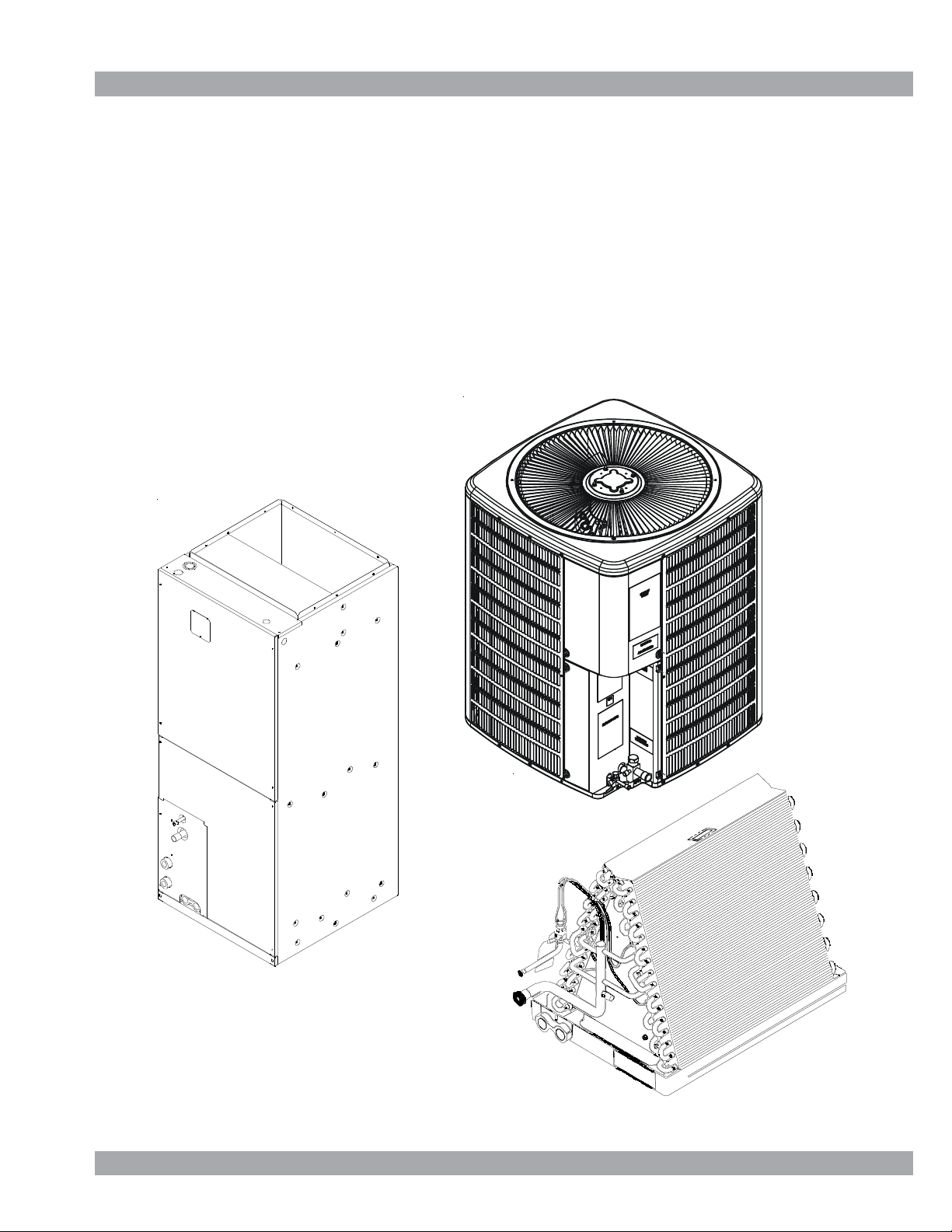
Service Instructions
SSX, ASX, GSX, DSX Condensing Units,
SSZ, ASZ, GSZ DSZ Split System Heat Pumps
with R-410A Refrigerant
Blowers, Coils, & Accessories
This manual is to be used by qualified, professionally trained HVAC technicians only. Goodman does not assume any responsibility for property
damage or personal injury due to improper service procedures or services
performed by an unqualified person.
Copyright © 2006 - 2009 Goodman Manufacturing Company, L.P.
RS6200006r11
April 2009
Page 2
IMPORTANT INFORMATION
IMPORTANT INFORMATION ..................................... 2 - 3
PRODUCT IDENTIFICATION .....................................4 - 11
ACCESSORIES......................................................13 - 23
PRODUCT DESIGN ................................................25 - 27
SYSTEM OPERATION ...........................................28 - 32
Pride and workmanship go into every product to provide our customers with quality products. It is possible, however, that
during its lifetime a product may require service. Products should be serviced only by a qualified service technician who is
familiar with the safety procedures required in the repair and who is equipped with the proper tools, parts, testing instruments
and the appropriate service manual. REVIEW ALL SERVICE INFORMATION IN THE APPROPRIATE SERVICE MANUAL BEFORE
BEGINNING REPAIRS.
IMPORTANT NOTICES FOR CONSUMERS AND SERVICERS
RECOGNIZE SAFETY SYMBOLS, WORDS AND LABELS
WARNING
T
HIS UNIT SHOULD NOT BE CONNECTED TO. OR USED IN CONJUNCTION WITH, ANY DEVI CES THAT ARE NOT DESIGN CERTIFI ED FOR US E WITH THI S UNIT OR HAV E NOT BEEN
TESTED AND APPROVED BY
FROM THE USE OF DEVICES THAT HAVE NOT BEE N APPROVED OR CERTIFED BY
GOODMAN. SERIOUS PROPERTY DAMAGE OR PERSONAL INJURY, REDUCED UNIT PERFORMANCE AND/OR HAZARDOUS CONDITI ONS MAY RESULT
TROUBLESHOOTING CHART .......................................33
SERVICE TABLE OF CONTENTS.................................34
SERVICING ............................................................35 - 72
ACCESSORIES WIRING DIAGRAMS ....................73 - 80
GOODM A N.
WARNING
T
O PREVENT THE RISK OF PROPERTY DAMAGE, PERSONAL INJURY, OR DEATH,
DO NOT STORE COMBUSTIBLE MATER IALS OR USE GASOLINE OR OTHER
FLAMMABLE LIQUIDS OR VAPORS IN THE VICINITY OF THIS APPL IANCE.
WARNING
G
OODMAN WILL NOT BE RESPONSIBLE FOR ANY INJURY OR PROPERTY DAMAGE ARISING FROM IMPROPER SERVICE OR SERVICE PROCEDURES.
I
F YOU INSTALL OR PERFORM SERVICE ON THIS UNIT, YOU ASSUME RESPONSIBILITY FOR ANY PERSONAL INJURY OR PROPERTY DAMAGE WHICH
MAY RESU LT.
M
ANY JURISDICTIONS REQU IRE A LICENSE TO INSTALL OR SERV ICE HEATING AND AIR CONDITIONING EQUIPMENT.
To locate an authorized servicer, please consult your telephone book or the dealer from whom you purchased this product.
For further assistance, please contact:
CONSUMER INFORMA TION LINE
GOODMAN® BRAND PRODUCTS
TOLL FREE
1-877-254-4729 (U.S. only)
email us at: customerservice@goodmanmfg.com
fax us at: (713) 856-1821
(Not a technical assistance line for dealers.)
Outside the U.S., call 1-713-861-2500.
(Not a technical assistance line for dealers.)
Your telephone company will bill you for the call.
email us at: hac.consumer.affairs@amanahvac.com
AMANA® BRAND PRODUCTS
TOLL FREE
1-877-254-4729 (U.S. only)
fax us at: (931) 438- 4362
(Not a technical assistance line for dealers.)
Outside the U.S., call 1-931-433-6101.
(Not a technical assistance line for dealers.)
Your telephone company will bill you for the call.
Page 3
IMPORTANT INFORMATION
SAFE REFRIGERANT HANDLING
While these items will not cover every conceivable situation, they should serve as a useful guide.
WARNING
REFRIGERANTS ARE H EAVIER T HAN AIR. THEY CAN "PUS H OUT" THE
OXYGEN IN YOUR LUNGS OR IN ANY ENCLOSED SPACE.
POSSI BLE DIFFI CULTY IN BRE ATHIN G OR DEATH:
EVER PURGE REFRIGERANT INTO AN ENCLOSED ROOM OR SPACE. BY
•
N
LAW, ALL REFRIGERANTS MUST BE RECLAIMED.
IF AN INDOOR LEAK IS SUSPECTED, THOROUGHLY VENTIL ATE THE AREA
•
BEFORE BEGINNING WORK.
IQUID REFRIGERANT CAN BE VERY COLD. TO AVOID POSSIBLE FROST-
•
L
BITE OR BL INDNESS, AVOID CONTACT W ITH REFR IGERANT AND WEAR
I
GLOVES AND GOGGLES.
SKIN OR EYES, SEEK MEDICAL HELP IMMEDIATELY.
A
LWAYS FOLLOW
•
AS POIS ONOUS GA S WILL BE PRODUC ED.
F LIQUID REFRIGERANT DOES CONTACT YOUR
EPA
REGULATIONS. NEVER BURN REFRIGERANT,
O AVO ID
T
WARNING
HE UNITED STATES ENVIRONME NTAL PROTECTION AGENCY ( "
T
HAS ISSUED VARIOUS REGULATIONS REGARDING THE INTRODUCTION AN D
DISPOSA L OF REFRI GERANTS INTRODUC ED INTO T HIS UNIT .
FOLLOW T HESE REGU LATIONS MAY HARM TH E ENVIRON MENT AND CAN
LEAD TO THE H IMPOSI TION O F SUBSTAN TIAL FIN ES.
MAY VARY BY JURISDICTION.
EPA OFFICE.
LOCAL
SHOULD QUEST IONS ARI SE, CO NTACT YOUR
THESE REGULATIONS
EPA
AILURE TO
F
WARNING
TO AVOID POSSIBLE EXPLOSION:
EVER APPL Y FLAME O R STEA M TO A REFR IGERAN T CYLINDE R. IF YOU
•
N
MUST HEA T A CYLIND ER FOR FAS TER CHARG ING, PARTI ALLY IMME RSE
IT IN WARM WATER.
NEVER FILL A CYLINDER MORE THAN 80% FULL OF LIQUID REFRIG ERANT.
•
NEVER ADD ANYTHING OTHER T HAN R-22 TO AN R-22 CYLINDER OR
•
R-410A TO AN R-410A CYLINDER. THE SERVICE EQUIPMENT USED MUST
BE LISTED OR CERTIFIED FOR THE TYPE OF REFRIGERANT USED.
TORE CYLIN DERS IN A COOL, DRY PL ACE. NEVER US E A CYLIND ER
•
S
AS A PLATFORM OR A ROLLER.
WARNING
TO AVOID POSSIBLE EXPLOSION, USE ONLY RETURNABLE (NOT DISPOSABLE)
SERVICE CYLINDERS WHEN REMOVING REFRIGERANT FROM A SYSTEM.
•
ENSURE THE CYLINDER IS FREE OF DAMAGE WHICH COULD LEAD TO A
LEAK OR EX PLOS ION.
•
")
ENSURE THE HYDROST ATIC TEST DATE DOES NO T EXCEED 5 YEARS.
•
ENSURE THE PRESSURE RATING MEETS OR EXCEEDS 400 LBS.
WHEN IN DOUBT, DO NOT USE CYLINDER.
WARNING
WARNING
SYSTEM CONTAMINANTS, IMPROPER SERVICE PROCEDURE AND/OR PHYSICAL
ABUSE AFFECTING HERMETIC COMPRESSOR ELE CTRICAL TERMINALS MAY
CAUSE DANGEROUS SYSTEM VENTING.
The successful development of hermetically sealed refrigeration compressors has completely sealed the compressor's
moving parts and electric motor inside a common housing,
minimizing refrigerant leaks and the hazards sometimes
associated with moving belts, pulleys or couplings.
Fundamental to the design of hermetic compressors is a
method whereby electrical current is transmitted to the
compressor motor through terminal conductors which pass
through the compressor housing wall. These terminals are
sealed in a dielectric material which insulates them from the
housing and maintains the pressure tight integrity of the
hermetic compressor. The terminals and their dielectric
embedment are strongly constructed, but are vulnerable to
careless compressor installation or maintenance procedures and equally vulnerable to internal electrical short
circuits caused by excessive system contaminants.
T
O AVOID POSSIBLE INJURY, EX PLOSION OR DEATH, PRACTICE SAFE
HANDLING OF RE FRIGERANTS.
In either of these instances, an electrical short between the
terminal and the compressor housing may result in the loss
of integrity between the terminal and its dielectric embedment. This loss may cause the terminals to be expelled,
thereby venting the vaporous and liquid contents of the
compressor housing and system.
A venting compressor terminal normally presents no danger
to anyone, providing the terminal protective cover is properly
in place.
If, however, the terminal protective cover is not properly in
place, a venting terminal may discharge a combination of
(a ) hot lubricating oil and refrigerant
(b ) flammable mixture (if system is contaminated
with air)
in a stream of spray which may be dangerous to anyone in the
vicinity. Death or serious bodily injury could occur.
Under no circumstances is a hermetic compressor to be
electrically energized and/or operated without having the
terminal protective cover properly in place.
See Service Section S-17 for proper servicing.
Page 4
PRODUCT IDENTIFICATION
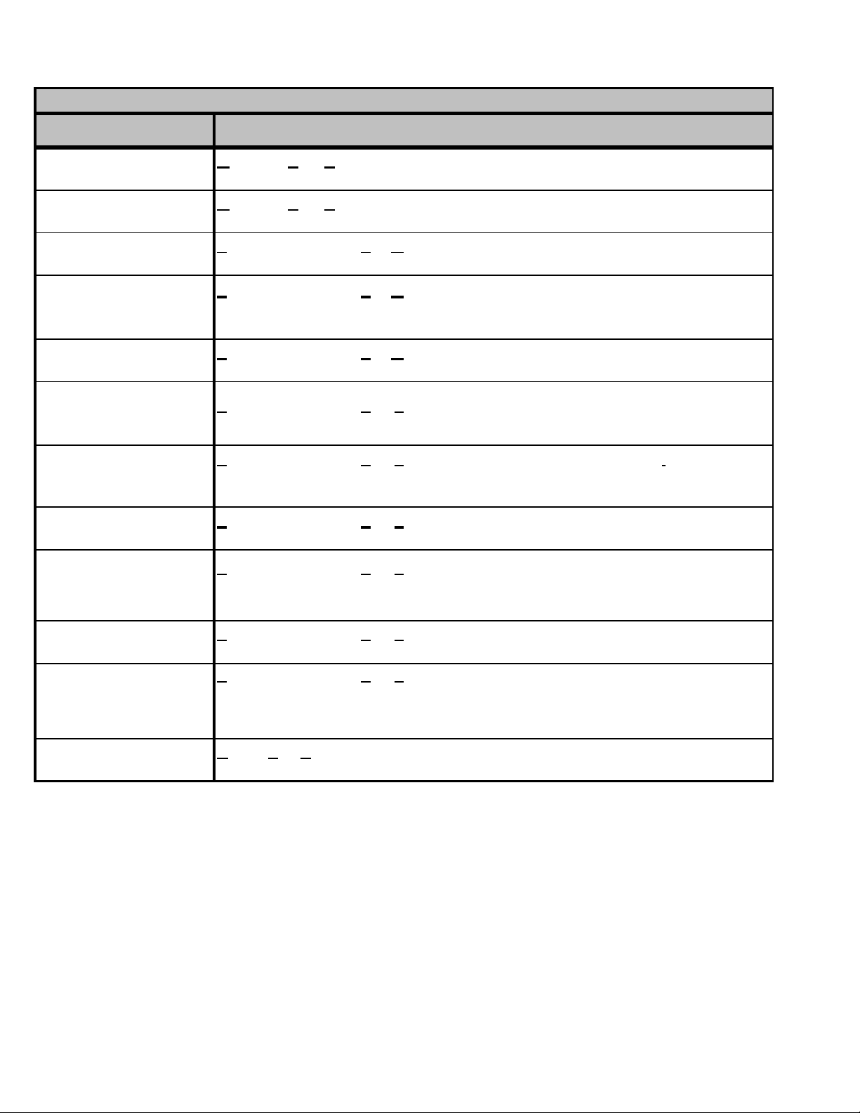
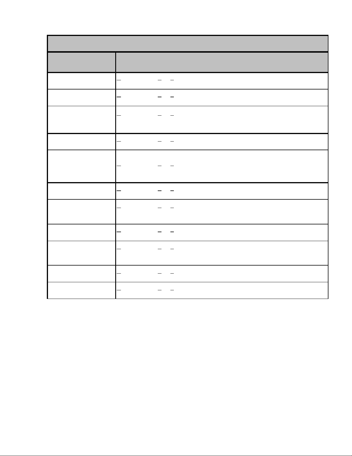
Split System Heat Pum ps R410A
Model # De sc r ipti on
oodman Spli t Z R4 10A Heat Pump 13 Seer R410A heat pum p u nits . Initial
GSZ1 3**1AA
GSZ1 3**1AB
SSZ140**1AA
SSZ140**1AB
SSZ140**1AC
G
releas e with Reg al Beloit motor .
oodman Spli t Z R4 10A Heat Pump 13 Seer R410A heat pum p u nits . Initial
G
releas e with Br oad Ocean mo tor.
pecial High Featu re Split Z R410A heat pump 14 S eer heat pum p units. I nitial
S
releas e of Goodman 14 S E E R Heat Pump R410A .
pecial High Featu re Split Z R4 1 0A he at pu mp 14 See r h ea t pu m p uni t s.
S
Intr oduc es new revis ions have scr ew locations mov ed i n the t op panel, bas e pans ,
louver s , and c ontr ol box covers.
pecial High Featu re Split Z R410A heat pump 14 Seer heat pump units. Models
S
contain B r oad Ocean motors .
SSZ140181AC
SSZ 140241AF
SSZ140301AD
SSZ 140361AF
SSZ140421AD
SSZ140[48-60]1AE
SSZ160**1AA
SSZ160**1AB
SSZ160[24-48]1AC
SSZ160601AD
SSZ160**1AC
DSZ160**1AA
S
pecial High Featu re Split Z R4 1 0A he at pu mp 14 See r h ea t pu m p uni t s.
Introduces new revisions adding mufflers to the discharge line.
Z
S
pecial High Featu re Split
revisions replace TXV & compensator with flowrator & accum ulator; adds mufflers
on SSZ14036` , 421, 481, 601.
pecial High Featu re Split Z R410A heat pump 16 S eer heat pum p units. I nitial
S
releas e of Goodman 16 S E E R Heat Pump R410A .
pecial High Featu re Split Z R4 1 0A he at pu mp 16 See r h ea t pu m p uni t s.
S
Intr oduc es new revis ions have scr ew locations mov ed i n the t op panel, bas e pans ,
louver s , and c ontr ol box covers.
pecial High Featu re Split Z R4 1 0A he at pu mp 16 See r h ea t pu m p uni t s.
S
Introduces new revisions adding mufflers to the discharge line.
S
pecial High Featu re Split Z R4 1 0A he at pu mp 16 See r h ea t pu m p
units.Int roduc es mo dels contain i ng the B road Ocean mo tor and added Mu ffler and
standar dized TXV, Compensator us ing the ASZ18 Se er weldment to the
SSZ160601AC.
eluxe Split Z He at Pump 16 S eer heat pump units . I ntr oduces Goodm an 2-stage
D
16 SEER heat pumps with R-410A.
R 410A heat pump 14 S eer heat pump
units . New
4
Page 5
PRODUCT IDENTIFICATION
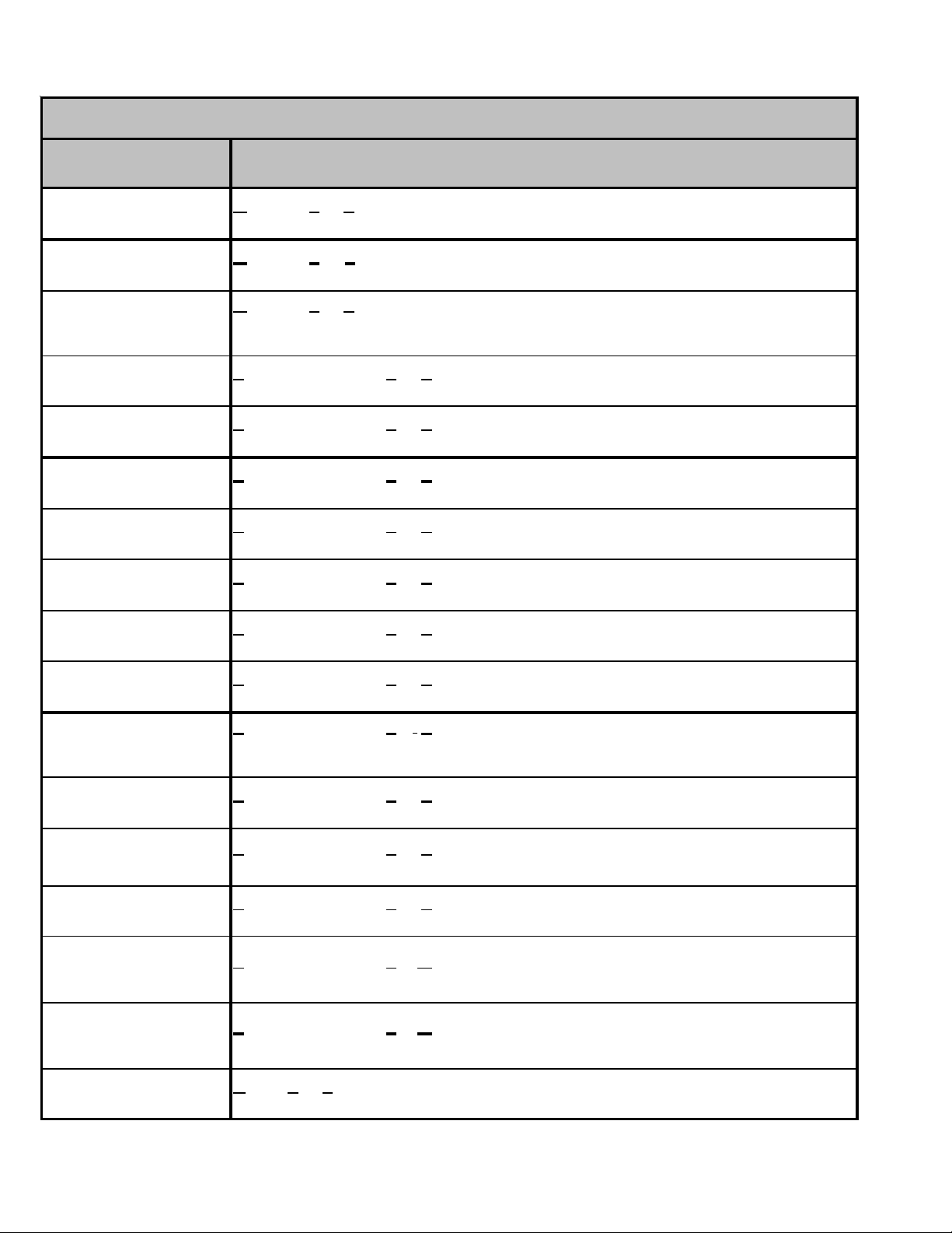
Split System Heat Pumps R410A
Mod e l # D e scr i p t ion
mana® Brand Split Z R410A he at pump 13 Seer heat pump uni ts . I n itial rel eas e
ASZ130**1AA
ASZ140**1AA
ASZ140**1AB
ASZ140**1AC
ASZ140181AD
ASZ140[24-36]1AE
ASZ14[42-48]1AD
ASZ140601AE
ASZ160**1AA
ASZ160**1AB
A
of Aman a® B r and 13 S E E R Heat Pum p R410A .
mana® Brand Split Z R410A he at pump 14 Seer heat pump uni ts . I n itial rel eas e
A
of Aman a® B r and 14 S E E R Heat Pum p R410A .
A
mana® Brand Split Z R410A heat pu mp 14 Seer heat pump units. Introdu ces new
revisions hav e s c r ew locations mo v ed in the to p panel, bas e pans, louver s , and
con trol box covers.
A
mana® Brand Split Z R410A he at pump 14 Seer heat pum p u nits. New rev ision s
have hor izontal sty le louv ers .
mana® Brand Split Z R410A he at pump 14 Seer heat pump uni ts . Adds ne w st eel
A
muff ler, and su c tion tubes w/sh oc k loop .
A
mana® Brand Split Z R410A he at pump 16 Seer heat pump uni ts . I n itial rel eas e
of Aman a® B r and 16 S E E R Heat Pum p R410A .
A
mana® Brand Split Z R410A heat pu mp 16 Seer heat pump units. Introdu ces new
revisions hav e s c r ew locations mo v ed in the to p panel, bas e pans, louver s , and
con trol box covers.
ASZ160**1AC
ASZ160**1AD
ASZ160241AD
ASZ160[36-60]AE
ASZ180**1AB
mana® Brand Split Z R410A he at pump 16 Seer heat pum p u nits. New rev ision s
A
have hor izontal sty le louv ers .
mana® Brand Split Z R410A he at pump 16 Seer heat pum p u nits. New rev ision s
A
add ed Muffl er and s tanda r diz ed TXV, Compensator using t he A S Z18 Seer
wel dm ent.
A
mana® Brand Split Z R410A he at pump 16 Seer heat pump uni ts . Adds ne w st eel
muff ler, and su c tion tubes w/sh oc k loop .
A
mana® Brand Split Z R410A he at pump 18 Seer heat pump uni ts . I n itial rel eas e
of Aman a® B r and 18 S E E R Heat Pum p R410A .
5
Page 6
PRODUCT IDENTIFICATION
Split System Air Conditioners R410A
M ode l # Des c ri pt io n
X
GSX 130**1AA
G
oodman Split
SEER R-410A Condensers with Regal Beloit motors
Con de ns er 13 S eer condens ing units . Introduction of G o odm a n 13
GSX 130**1AB
GSX 130**1BA
SSX140**1AA
SSX140**1AB
SSX14018,241AC
SSX140301AC
SSX14036-601AC
SSX14030,361AD
SSX140421AD
oodman Spli
G
SEER R-410A Condensers with Broad Ocean mot ors.
G
oodman Split
SEER R-410A Condensers, using Quant um Leap coils. Units will have new louver s
becaus e units ar e s ma ller. Pisto n si z e c hange. Other comp o nen t s unc h ang ed.
S
pecial High Feature Split
Good m an 14 S E E R A C 410A.
pecial High Feature Split
S
scre w locations mov ed in the top panel, base pans, louvers, an d contr ol box covers.
S
pecial High Feature Split
coils by removing [1] haripin.
S
pecial High Feature Split
Broad Ocean motor 0131M00060
pecial High Feature Split
S
Broad Ocean motor 0131M00061
S
pecial High Feature Split
coils by removing [1] haripin.
pecial High Feature Split
S
SSX140421A in 29" base pan
Co ndenser 13 Se er c ondensi ng uni t s . I ntr oduction of Goodma n 13
t X
X
Con de ns er 13 S eer condens ing units . Introduction of G o odm a n 13
X
Condens er 14 Seer condensing unit s . Initial release of
on denser 14 Seer condensi ng units. Revi si ons ha ve
X
C
X
Condenser 1 4 Seer condens ing units . Revised condense r
X
Con d enser 14 Seer condens ing units. Mo del c ontain the
Con d enser 14 Seer condens ing units. Mo del c ontain the
X
X
Condenser 1 4 Seer condens ing units . Revised condense r
Condens er 14 S eer condensing unit s. I ntroduces
X
SSX140421BA
SSX14030-421AE
SSX140[18-36]1BA
SSX140421CA
SSX160**1AA
SSX160**1AB
SSX160**1AB
DSX160**1AA
pecial High Feature Split
S
SSZ140421B * in 29 b as e pan and it will the re duce the unit c har ge from 1 80 oz. to 170
oz. and replace the 1/ 4 h p outdo or unit motor with 1/ 6 h p mot or.
pecial High Feature Split
S
coils by removing [1] haripin.
pecial High Feature Split
S
Good m an 14 S E ER R-410A Condensers , u s ing Quantum Le ap Coils .
S
pecial High Feature Split
16 SEER AC 410A
S
pecial High Feature Split
scre w locations mov ed in the top panel, base pans, louvers, an d contr ol box covers.
pecial High Feature Split
S
scre w locations mov ed in the top panel, base pans, louvers, an d contr ol box covers.
D
eluxe Split X Condenser 16 Seer condensing units. Introduces Goodman 2-stage, 16
SEER condensi ng units with R-410A.
Condens er 14 S eer condensing unit s. Revision for
X
Condenser 1 4 Seer condens ing units . Revised condense r
X
Condenser 1 4 S eer condens i ng units . Int roducti o n of
X
X
Condens er 16 S eer condensing unit s. I ntroduces Goodman
X
Con d ens er 16 S eer condens ing units . New re v is ions hav e
Con d ens er 16 S eer condens ing units . New re v is ions hav e
X
6
Page 7
PRODUCT IDENTIFICATION
Split System Air Conditioners R410A
M ode l # Des c ri ption
ASX130* *1AA
ASX130* *1BA
ASX140* *1AA
ASX140* *1AB
ASX140**1AC
ASX14018-361AD
ASX140421AD
ASX1404 21BA
Aman a® Brand
of Aman a® Brand Deluxe 13 SEER AC R410A conditioners.
Aman a® Brand
Brand 13 SEER R-410A Condensers, using Quantum Leap Coils. Units will have new
louvers since unit s are small er. Piston size change; other components unch anged.
Aman a® Brand
of Aman a® Brand Deluxe 14 SEER AC R410A conditioners.
Aman a® Brand
scre w locations moved in the top pa nel, bas e pans, louv ers , and c ontr ol box c ov ers.
Aman a® Brand
horizontal style louvers.
Aman a® Brand
by re mov ing (1) hair pin.Reduce R410A quantity by 6 ounc es
Aman a® Brand
in 29 " bas e pan
Aman a® Brand
in 29" platfor m. It will t he reduce the unit charge from 180 o z . to 170 oz . and replace the
1/4 hp ou td oor unit mo to r wit h 1/6 hp motor.
S
plit X Co ndenser 13 Se er co ndens ing unit s . Ini ti al r ele ase new models
plit X Co ndenser 13 Se er co ndens ing unit s . Intr oduction of Am ana®
S
plit X Co ndenser 14 Se er co ndens ing unit s . Ini ti al r ele ase new models
S
S
plit X Co ndenser 14 Seer co ndens in g unit s . New r ev is ions hav e
S
plit X Co ndenser 14 Seer co ndens in g units . The new r ev is ions hav e
plit X Co ndenser 14 Se er co ndens ing unit s . Rev ised cond ens er coils
S
S
plit X Co ndenser 14 Se er co ndens ing unit s . Intr oduces AS X 140421A
S
plit X Co ndenser 14 Se er co ndens ing unit s . Rev ision for A SX 1 40421
ASX140[18-36]1BA
ASX140421CA
ASX160* *1AB
ASX160**1AC
ASX180* *1AB
Aman a® Brand
Brand 14 SEER R-410A Condensers, using Quantum Leap Coils.
Aman a® Brand
scre w locations moved in the top pa nel, bas e pans, louv ers , and c ontr ol box c ov ers.
Aman a® Brand
horizontal style louvers.
Aman a® Brand
of Aman a® Brand Deluxe 16 SEER AC R410A conditioners.
plit X Co ndenser 14 Se er co ndens ing unit s . Intr oduction of Am ana®
S
S
plit X Co ndenser 16 Seer co ndens in g unit s . New r ev is ions hav e
plit X Co ndenser 16 Seer co ndens in g units . The new r ev is ions hav e
S
S
plit X Co ndenser 18 Se er co ndens ing unit s . Ini ti al r ele ase new models
7
Page 8
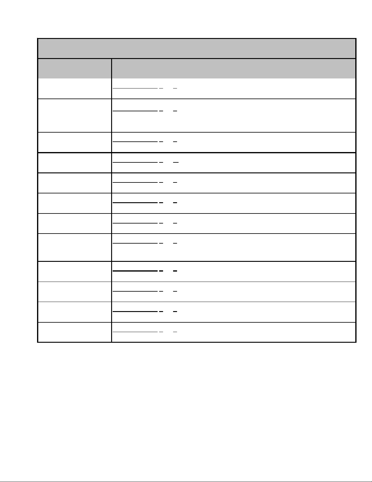
PRODUCT IDENTIFICATION
Single Piece Air Handlers
Model # Description
A
Single Piece R Multi-Position PSC Motor Unpainted Flowrater Introducation
ARUF****16AA
ARUF364216AB
ARUF486016AB
ARUF364216AC
ARUF****16BA
ARUF****1BA
of new 13 SEER Air Handler Models. All Models will be suitable for use with R22 and R-410A
A
Single Piece R Multi-Position PSC Motor Unpainted Flowrater.Revision
replaces the current spot welded blower housing with the same cinched or
crimped design used on the 80% furnace line.
A
Single Piece R Multi-Position PSC Motor Unpainted Flowrater.Revision
replaces the current spot welded blower housing with the same cinched or
crimped design used on the 80% furnace line.
A
Single Piece R Multi-Position PSC Motor Unpainted Flowrater.Revision
replaces the current spot welded blower housing with the same cinched or
crimped design used on the 80% furnace line.
A
Single Piece R Multi-Position PSC Motor Unpainted Flowrater. Revision
replaces all ARUFcoils using wavy fin with louver enhanced fin.
Single Piece R Multi-Position PSC Motor Unpainted Flowrater Introducation
A
of R-22 Only Air Handlers.
ARPF****16AA
ARPF364216AB
ARPF486016AB
ARPF****16BA
ARPF****1BA
ADPF****16AA
ADPF364216AB
ADPF486016AB
Single Piece R Multi-Position PSC Motor Painted Flowrater Introducation of
A
new 13 SEER Air Handler Models. All Models will be suitable for use with R-22
and R-410A
A
Single Piece R Multi-Position PSC Motor Painted Flowrater. Revision
replaces the current spot welded blower housing with the same cinched or
crimped design used on the 80% furnace line.
A
Single Piece R Multi-Position PSC Motor Painted Flowrater. Revision
replaces the current spot welded blower housing with the same cinched or
crimped design used on the 80% furnace line.
Single Piece R Multi-Position PSC Motor Painted Flowrater. Revision
A
replaces all ARPFcoils using wavy fin with louver enhanced fin.
Single Piece R Multi-Position PSC Motor Painted Flowrater. Introducation of
A
R-22 Only Air Handlers.
Single Piece Downflow PSC Motor Unpainted Flowrater. Introducation of
A
new 13 SEER Air Handler Models. All Models will be suitable for use with R-22
and R-410A
A
Single Piece Downflow PSC Motor Unpainted Flowrater. Revision replaces
the current spot welded blower housing with the same cinched or crimped
design used on the 80% furnace line.
A
Single Piece Downflow PSC Motor Unpainted Flowrater. Revision replaces
the current spot welded blower housing with the same cinched or crimped
design used on the 80% furnace line.
A
Single Piece Downflow PSC Motor Unpainted Flowrater. Revision replaces
ADPF304216AC
ADPF****1BA
the current spot welded blower housing with the same cinched or crimped
design used on the 80% furnace line.
Single Piece Downflow PSC Motor Unpainted Flowrater Revision replaces
A
all ARPFcoils using wavy fin with louver enhanced fin.
8
Page 9
PRODUCT IDENTIFICATION
-
S ing le Pie ce Air Ha n dl ers
Mode l # De s cription
Single Piece E Multi- P os ition Var iable- S pe ed Painted Flowrator. Introducation of
A
AEPF****16AA
AEPF****16BA
AEPF****16BB
AEPF****16CA
AEPF****1BA
new 13 S EER A ir Han dler Models . A ll M odels will b e s uitable for use with R- 22 and
R-410A
Single Piece E Multi- P os ition Var iable- S pe ed Painted Flowrator. Revision
A
introduc es new m odels adding l ower kw hit kits on the S& R plate
Single Piece E Multi- P os ition Var iable- S pe ed Painted Flowrator. Revision
A
replaces t he c ur rent spot welded blower housin g w ith the sam e cinc h ed o r crimped
design use d on the 80% furnace l ine.
A
Single Piece E Multi- P os ition Var iable- S pe ed Painted Flowrator. Revision
replaces all A R P Fc oils us i ng wavy fin with louver enha nced fin.
Single Piece E Multi- P os ition Var iable- S pe ed Painted Flowr at or Intr o ducti o n of R
A
22 O nly Air Han dlers.
AEPF313716AA
ASPF313716AA
ASPF****16AA
ASPF****16BA
AWUF****1AA
AWUF****16AA
AWUF3005-101AA
AWUF****1BA
AWUF370**16AA
(ASPF)
(AEPF)
. Introduction of
A
Single Piece E Multi- P os ition Var iable- S pe ed Painted Flowrator
Sin gle Piece S Mult i -Position EEM mo tor Painted Flowrator
3-Ton Air H andler u nits with 3-row co i l.
Single Piece S Multi-Position EEM mot or Painted Flowrator. Introduces new
A
ASPF Air Handlers
Single Piece S Multi-Position EEM mot or Painted Flowrator. Revision introuces
A
modi fied AS P F control sc hem e, t o ensure blower operation during and aft er ca ll for
hea t on units with heat k its and replac ing wavy fin with louv er enhanc ed fi n on c oil
Single Piece Air Handler Wal l Mount Unpainted Flo wrator. In troduc es 13 SEER
A
Dayton w all moun t air handlers
Single Piece Air Handler Wal l Mount Unpainted Flo wrator. In troduc es 13 SEER
A
Dayton wall mount air handlers. All Models will be suitable for use with R-22 and R410A
Single Piece Air Handler Wal l Mount Unpainted Flo wrator. In troduc es 13 SEER
A
Dayton wall moun t air handlers using a Burr Oak Louvered Fin coil.
A
Single Piece Air Handler Wal l Mount Unpainted Flowr ator . Revis i on replaces
cur r ent w avey fin design with new louv e r ed fin desi g n
Single Piece Air Handler Wal l Mount Unpainted Flowrator. Introduction of
A
AWUF37 Air Handler s for us e with R-22 and R410A .
and
A
AWUF****16BA
ACNF****1AA
ACNF****16AA
ACNF****1BA
AH**-1*
Single Piece Air Handler Ceiling Mount N Un ca s ed Flow rater. Revis ion has
A
louv er fins & re places c opper tube ha ir pins with aluminum hairpins .
A
Single Piece Air Handler Ceiling Mount N Un ca s ed Flow rater. Revis ion release
all mo de ls o f 13 SEE R Day ton u nc a s ed air handlers.
Single Piece Air Handler Ceiling Mount N Un ca s ed Flow rater. Revis ion release
A
all mo dels of 13 SEE R Day ton u nc a s ed air handlers.All Models will be suitable fo r
use wit h R- 22 and R-410A
Single Piece Air Handler Ceiling Mount N Un ca s ed Flow rater. Revis ion re plac es
A
cur r ent w avey fin design with new louv e r ed fin desi g n
A
Single Piece Air Handler Hydronic Air Handler. Revis ion replaces the time delay
r e lay in the AH a ir ha ndl er s w it h t he UTE C t ime del ay co ntr ol bo ar d.
9
Page 10
PRODUCT IDENTIFICATION
,
MBR/MBE Air Handler s
Mo del # Descripti on
odular Blower R Mul ti-Position PSC Motor. Intro duce s module blower w ith PSC
MBR****AA-1AA
MBE****AA-1AA
MBE****AA-1BA
Mo del # Descripti on
CAUF*****6AA
CAUF*****6BA
M
bl ow er mo tor .
M
odular Blower E Multi-Position Variable-Speed. Introduces module blower with
variable speed blower m otor.
odular Blower E Multi-Position Variable-Speed.Revision introduces new models
M
adding l ower kw hit ki ts on the S &R plate
Evaporator Coils
C
Ind oor Coil A Upfl ow/Downflow Uncased Flo wr ator . Introduce s 13 S E ER CAUF
Dayton Upflow/Downflow coils.
Ind oor Coil A Upfl ow/Downflow Uncased Flo wr ator . Rev ision releases Bur r Oak
C
Lou ver ed Fin in place of the Wavy Fin curr ently in p roduction.
CAPF*****6AA
CAPF*****6BA
CAPF/CAUF36***CA
CHPF*****6AA
CHPF*****6BA
CHPF2430B6CA
CHPF3636B6CA
CHPF3642[ C-D]6CA
CHPF3743C6BA
CHPF3743D6CA
CSCF*****6AA
Ind oor Coil A Upfl ow/Downflow Painted Flowra tor . Introduces 13 S E ER CAPF
C
Dayton Upflow/Downflow coils.
C
Ind oor Coil A Upfl ow/Downflow Painted Flowr ator. Revis ion re leases B ur r Oak
Lou ver ed Fin in place of the Wavy Fin curr ently in p roduction.
Ind oor Coil A Upfl ow/Downflow [Painted or Uncased] Flow rator. Re vision
C
redesign s for perf or m anc e im pr o vement from 2 r ow to 3 row.
C
Ind oor Coil Horizontal A Coil Painted Flowrator. Release 13 SEER CHPF
hori zontal A coil.
C
Ind oor Coil Horizontal A Coil Painted Flowrator. Release 13 SEER CHPF
horizontal A coil. Revision releases Burr Oak Louvered Fin in place of the Wa vy
Fin c urrently in product i on . The r ows change by one, (i.e. 4 row to 3 ro w; 3 r o w to
2 row) where applicab le.
C
Ind oor Coil Horizontal A Coil Painted Fl owrator . 13 SEE R CHPF horiz ontal A
coil, r evis ion has louv er f i ns & re places co pper tube hair pi ns with a l uminum
hairpins.
C
Ind oor Coil S Horizontal Slab Coil C Upainted Flowrator. Rele ase 13 SEER
CSCF sla b h or izontal coil.
10
CSCF*****6BA
C
Ind oor Coil S Horizontal Slab Coil C Upainted Flowrator. Revision releases Burr
Oak Louver ed Fin in p l ac e o f the Wavy F in curr ently in pr oduct ion. The r ows
chan ge by one, ( i. e. 4 row t o 3 row; 3 r ow to 2 row ) whe r e app licable.
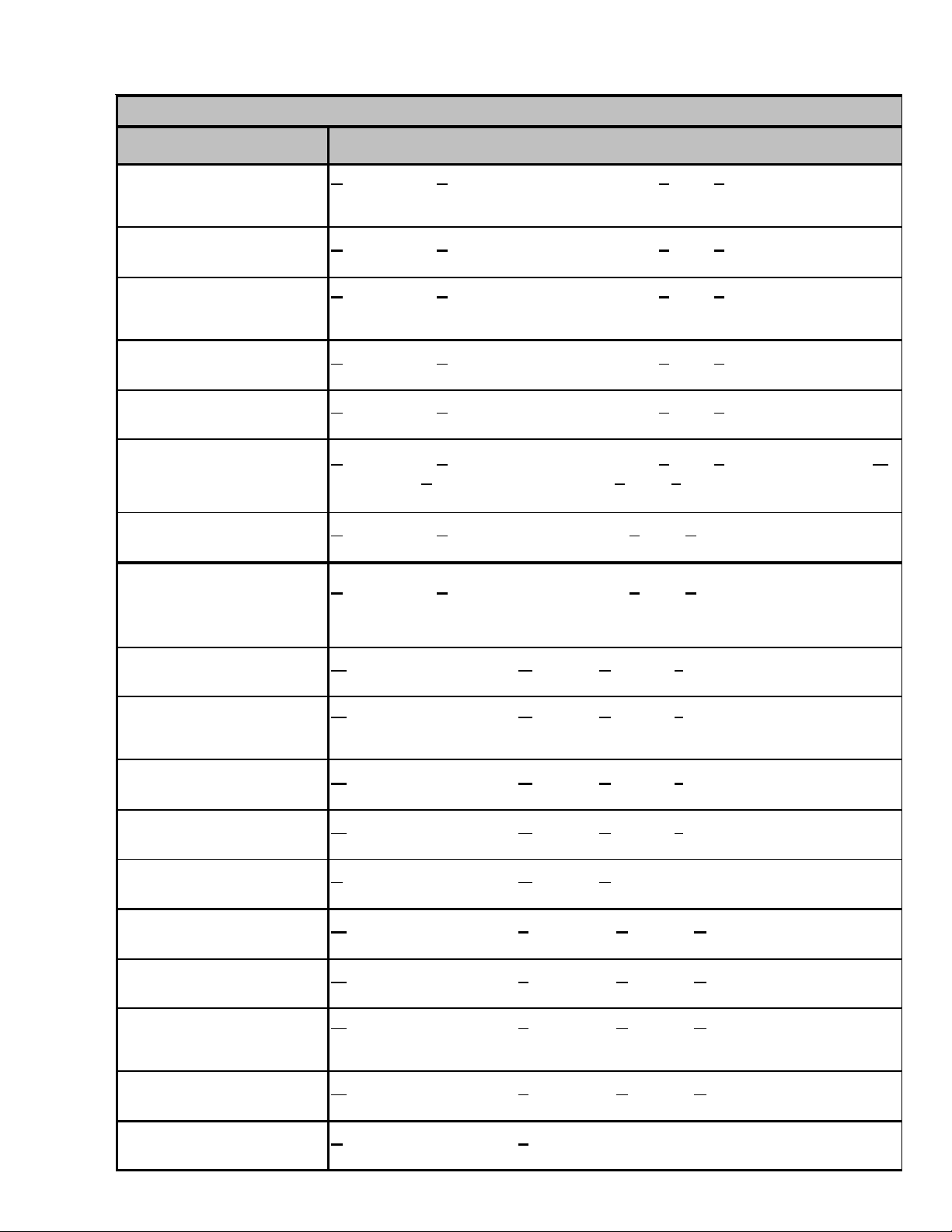
Page 11

PRODUCT IDENTIFICATION
A
A
A
SSZ14361AA
BRAND:
G: Go odman
(Standa rd
Fe ature Set)
S: Goodman®
(High
Fe ature Set)
: Amana®
Brand
Deluxe
D: Deluxe
Go odman®
®
PRODUCT
FAMILY:
S: Split System
SEER:
SEER Rating
NO MINAL
CAP ACITY:
018 : 1.5 Tons
024: 2 Tons
030 : 2.5 Tons
036: 3 Tons
042 : 3.5 Tons
048: 4 Tons
060: 5 Tons
MINOR
R EVISIO N:
: Init ial Release
MAJOR
REVISI ON:
: Initial Release
PRODUC T
TYPE:
X: Cond ens er R-4 10A
Z: Heat P ump R- 410A
ELECTRICAL:
1: 208-230V/1ph/60Hz
3: 208-230v/3ph/60Hz
4: 460v/3ph/ 60Hz
11
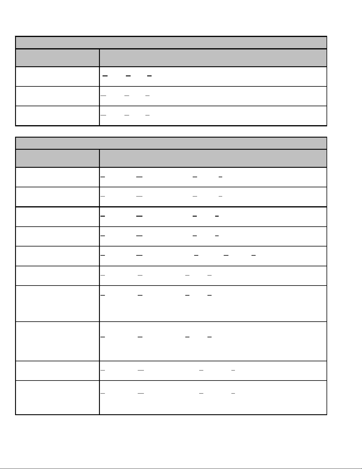
Page 12
PRODUCT IDENTIFICATION
C A P F 1824 A 6 A
PRODUCT
TYPE:
C: Indoor Coil
APPLICATION
A: U pflow/D ownflow C oil
H: Horizontal A Coil
S: Ho r izontal Slab Coil
EXPA NSION
DEVICE:
F: Flowrater
CABINET FINISH:
U: Unpai nted
P: Painte d
N: Unpain ted Case
REVISION
A: Revision
REFRIGERANT
CHARGE:
6: R-410A or R-22
2: R- 22
4: R- 410a
NOMINAL WI DTH FOR GAS FURNACE
A: Fits 14" Fur nace Cabinet
B: Fits 17 1 /2" F ur nace Cabi net
C: Fits 21 " Fu rnac e Cabi net
D: F its 24 1/ 2" Furnace Cabinet
N: Does Not Apply (Horizon tal S lab Coils )
NOMINAL CAPACITY RANGE
@ 13 SEER
1824: 1 1/ 2 to 2 T on s
3030: 2 1/ 2 Ton s
36 36 : 3 To ns
3642 : 3 to 3 1/2 Tons
48 60 : 4 & 5 T on s
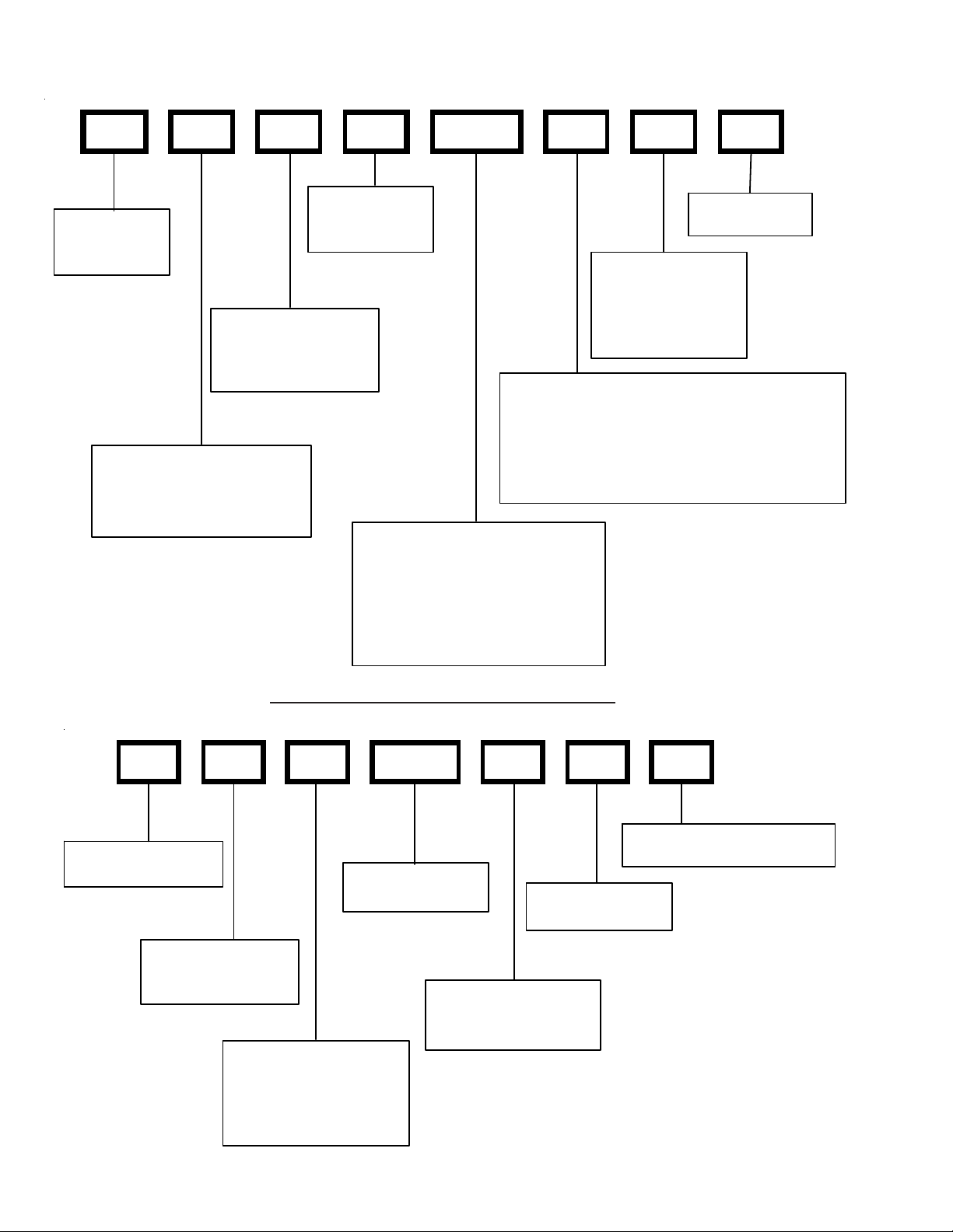
MB R 8 00 A A 1
DESIGN SERIES:
MB: Modular Blower
MOT OR TY PE:
R: Constant Spe ed
E: Variable Speed
12
FACTORY HEAT
00: No Hea t
AIRFL OW DE LIV E RE D
08 : 800 C FM
12 : 1200 CFM
16 : 1600 CFM
20 : 2000 CFM
ELECTRICA L SUPPLY:
1 : 208-230V / 60hZ/ 1 ph
D ESIGN SERIES
A: First Series
CIRCUIT BREAKER
A: No Circuit Breaker
B: Circuit Breaker
Page 13
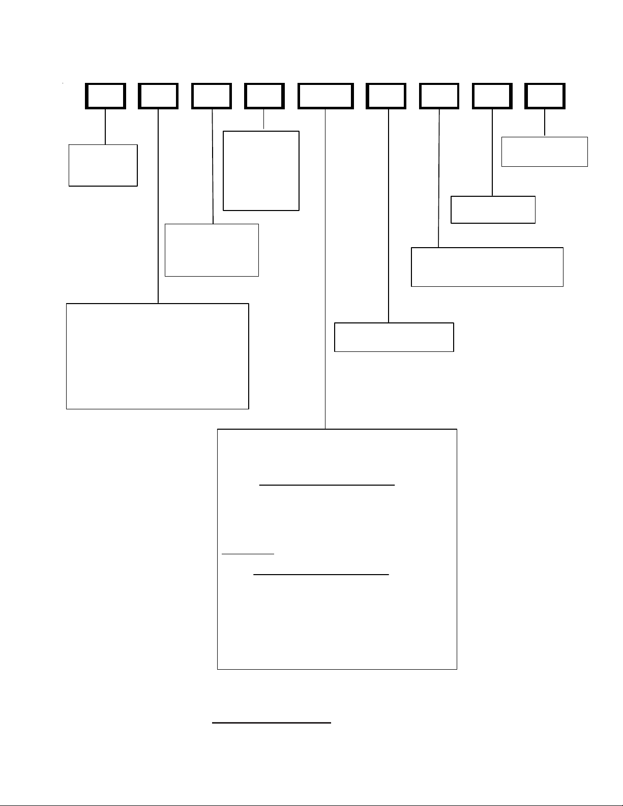
PRODUCT IDENTIFICATION
A W U F 3642 1 6 A A
EXPA NSION
PRODUCT
TYPE:
A: Air Handler
CABINE T FINIS H :
U: Unpainted
P: Paited
N: Uncased
A PPLICATION
C: C eiling M ount P S C Motor
D: Downflow PSC Motor
E: Mul ti-P os ition Varible-Speed M otor
S: Ene rgy-Efficient Motor
R: Multi-Position PSC Motor
T: Coated Coils
W: Wall Mount PSC Motor
DEVI CE :
F: Flowrater
T: TXV
(Expansion
Device)
MINOR
REVISION*
MAJOR
REVISION*
RE FRIGE RANT CHA RGE:
No Digit: R-22 Only
6 : R-41 0A or R-22
ELECTRICAL:
1: 208-2 30V/1ph/60Hz
NOMINAL CAPACITY RAN GE:
@ 13 SEER
Dedic at ed Applic at ion
3 6 36: 3 To ns
Multi-Position & Downflow Applications
3 1 37: 3 To ns
364 2: 3 - 3 1/2 Tons
1830: 1 1/2 - 3 1/2 Tons
@10 SEER
1729: 1 1/2 - 2 1/2 Tons (for export systems)
Ceiling Mount & Wall Mount Applications
(Nominal Cooling Capacity/Electric Heat kW)
1805: 1 1/2 Tons Cooling / 5 kW Electric Heat
2405 : 2 To ns Co o lin g / 5 kW E le c tr i c He at
3608 : 3 To ns Co o lin g / 8 kW E le c tr i c He at
3705 : 3 To ns Co o lin g / 5 kW E le c tr i c He at
3708 : 3 To ns Co o lin g / 8 kW E le c tr i c He at
All Airhandlers use DIRECT DRIVE MOTORS. Power supply is AC 208-230v, 60 hz, 1 phase.
13
Page 14
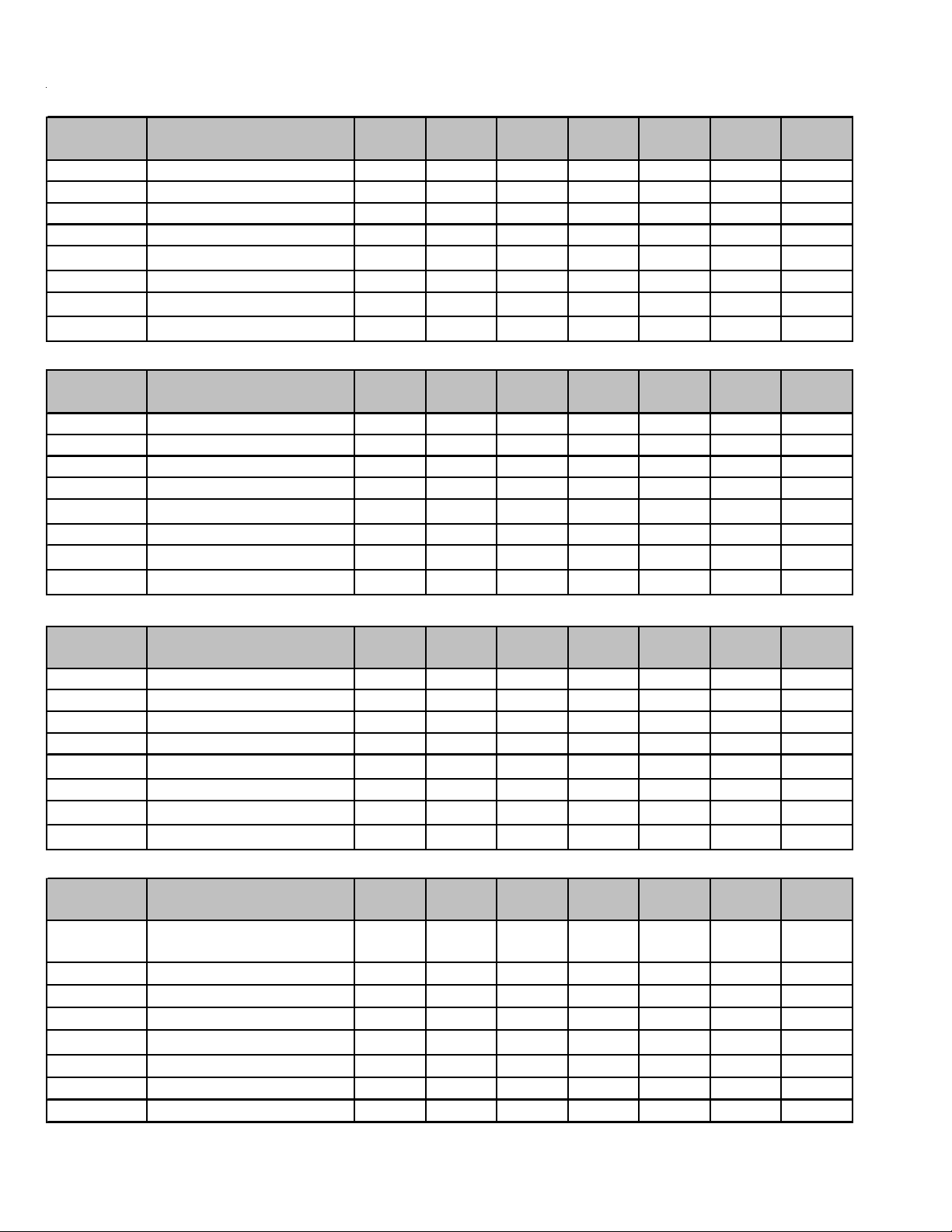
ACCESSORIES
ASX13
Model Description
ASX13
018
ASC01Anti-Short Cycle Kit XXXXXXX
CSR-U-1 Hard-start Kit X X X X
CSR-U-2 Hard-start Kit X X X X
CSR-U-3 Hard-start Kit XX
FSK01A
1
Freeze Protection Kit XXXXXXX
TX2N4³ TXV Kit X
TX3N4
TX5N4
2
2
TXV Kit XXX
TXV Kit XXX
GSX13
Model Description
ASC01Anti-Short Cycle Kit XXXXXXX
CSR-U-1 Hard-start Kit X X X X
CSR-U-2 Hard-start Kit X X X X
CSR-U-3 Hard-start Kit XX
FSK01A
1
Freeze Protection Kit XXXXXXX
TX2N4³ TXV Kit X
TX3N4
TX5N4
2
2
TXV Kit XXX
TXV Kit XXX
GSX13
018
ASX13
024
GSX13
024
ASX13
030
GSX13
030
ASX13
036
GSX13
036
ASX13
042
GSX13
042
ASX13
0418
GSX13
0418
ASX13
060
GSX13
060
SSX14
Model Description
SSX14
018
ASC01Anti-Short Cycle Kit XXXXXXX
CSR-U-1 Hard-start Kit X X X X
CSR-U-2 Hard-start Kit X X X X
CSR-U-3 Hard-start Kit XX
FSK01A
1
Freeze Protection Kit XXXXXXX
TX2N4³ TXV Kit X
TX3N4
TX5N4
2
2
TXV Kit XXX
TXV Kit XXX
SSX14
024
SSX14
030
SSX14
036
SSX14
042
SSX14
048
SSX14
060
ASX14
Model Description
ASC01 Anti-Short Cycle Kit
CSR-U-1 Hard-start Kit
ASX14
018
XXXXXXX
XXXX
CSR-U-2 Hard-start Kit
CSR-U-3 Hard-start Kit
1
FSK01A
TX2N4³ TXV Kit
Freeze Protection Kit XXXXXXX
X
TX3N4³ TXV Kit
TX5N4³ TXV Kit
1
Installed on indoor coil
2
Required for heat pump applications where ambient temperatures fall below 0°F with 50% or higher relative humidy.
³ Field-installed, non-bleed, expansion valve kit — Condensing units and heat pumps with reciprocating compressors require the use of
ASX14
024
ASX14
030
ASX14
036
XXXX
XXX
ASX14
042
ASX14
048
ASX14
060
XX
XXX
14
Page 15
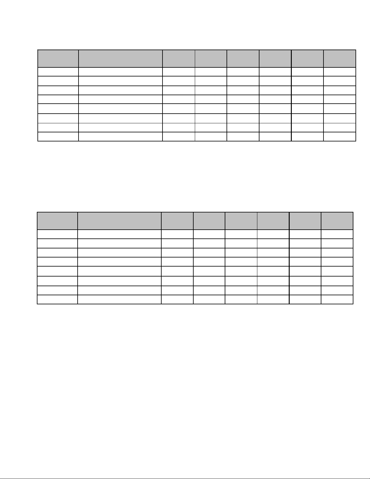
ACCESSORIES
DSX/SSX16
Model Description
ASC 01 An ti - Sh o rt Cy cl e Ki t
CSR - U -1 Ha r d -sta r t Ki t
D/SSX16
024
XXXXXX
XXX
D/SSX16
030
D/SSX16
036
D/SSX16
042
D/SSX16
048
D/SSX 16
CSR - U -2 Ha r d -sta r t Ki t X X X X
CSR - U -3 Ha r d -sta r t Ki t
1
FSK01A
TX2N4³ TXV Kit
TX3N4³ TXV Kit
TX5N4³ TXV Kit
1
Installed on indoor coil
2
Required for heat pump applications where amb ient temperatures fall be low 0°F with 50% or higher relative humidy.
³ Field-installed, non-bleed, expansion valve kit — Condensing units and heat pumps with reciprocating compressors require th e use of
start-assist components when used in conjunction with an indoor coil using a non-bleed thermal expansion valve refrigerant meter ing
device.
Freeze Pr otec t ion Kit X X X X X X
X
XX
XXX
XX
ASX16
Model Description
ASC 01 Anti- S ho r t Cycle Ki t
CSR-U - 1 Har d- sta r t K i t
ASX16
024
XXXXXX
XXX
CSR-U - 2 Har d- sta r t K i t X X X X
CSR-U - 3 Har d- sta r t K i t
1
FSK01A
TX2N4³ TXV Kit
Freeze Protection Kit X X X X X X
X
TX3N4³ TXV Kit
TX5N4³ TXV Kit
1
Installed on indoor coil
2
Required for heat pump applications where ambient temperatures fall below 0°F with 50% or higher relative humidy.
³ Field-installed, non-bleed, expansion valve kit — Condensing units and heat pumps with reciprocating compressors require the use of
start-assist components when used in conjunction with an indoor coil using a non-bleed thermal expansion valve refrigerant meter ing
device.
ASX1 6
030
ASX16
036
XX
ASX16
042
ASX1 6
048
ASX16
XX
XXX
060
060
15
Page 16
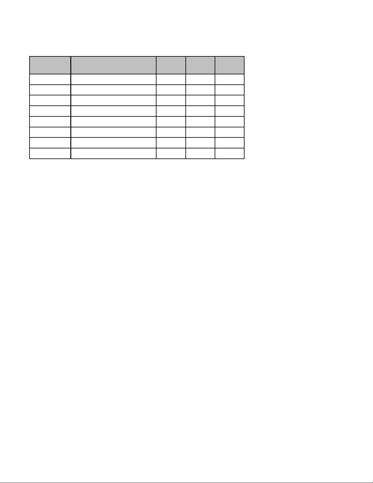
ACCESSORIES
ASX18
Model Description
ASC01 Anti-Short Cycle Kit
CSR-U-1 Hard-start Kit
CSR-U-2 Hard-start Kit
CSR-U-3 Hard-start Kit
1
FSK01A
TX2N4³ TXV Kit
TX3N4³ TXV Kit
TX5N4³ TXV Kit
1
Installed on indoor coil
2
Required for heat pump applications where ambient temperatures fall below 0°F with 50% or higher relative humidy.
³ Field-installed, non-bleed, expansion valve kit — Condensing units and heat pumps with reciprocating compressors req uire the use of
start-assist components when used in conjunction with an indoor coil using a non-bleed thermal expansion valve refrigerant metering
device.
Freeze Protection Kit
ASX18
036
XXX
X
XXX
XXX
X
ASX18
048
XX
XX
ASX18
060
16
Page 17
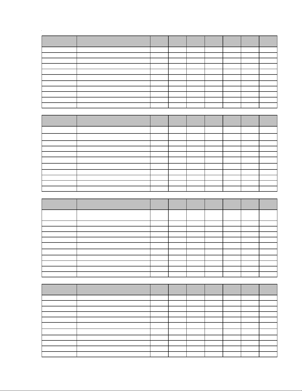
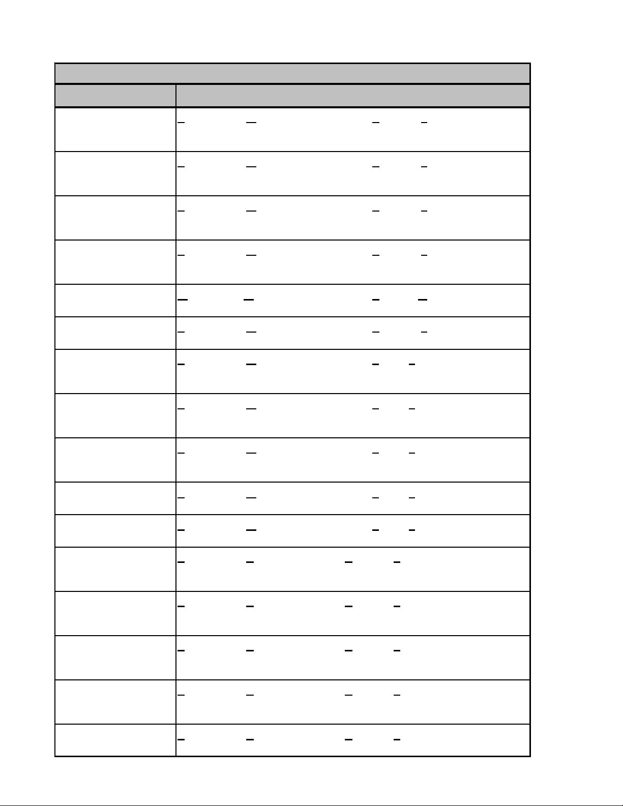
ACCESSORIES
ASZ13
Model Description
AFE18-60A All-Fuel Kit XXXXXXX
ASC01 Anti-Short Cycle Kit XXXXXXX
CSR-U-1 H ard-start Kit X X X X
CSR-U-2 H ard-start Kit XXXX
CSR-U-3 H ard-start Kit XX
1
FSK01A
OT/EHR18-60 Emergency Heat Relay kit X X X X X X X
OT18-60A² Outdoor Thermostat w/ Lockout Stat X X X X X X X
TX2N4³ TXV Kit X
TX3N4³ TXV Kit XXX
TX5N4³ TXV Kit XXX
Freeze Protection Kit XXXXXXX
ASZ13
018
GSZ13
Model Description
AFE18-60A All-Fuel Kit XXXXXXX
ASC01 Anti-Short Cycle Kit XXXXXXX
CSR-U-1 H ard-start Kit X X X X
CSR-U-2 H ard-start Kit XXXX
CSR-U-3 H ard-start Kit XX
1
FSK01A
OT/EHR18-60 Emergency Heat Relay kit X X X X X X X
OT18-60A² Outdoor Thermostat w/ Lockout Stat X X X X X X X
TX2N4³ TXV Kit X
TX3N4³ TXV Kit XXX
TX5N4³ TXV Kit XXX
Freeze Protection Kit XXXXXXX
GSZ13
018
SSZ14
Model Description
SSZ14
018
ASZ13
024
GSZ13
024
SSZ14
024
ASZ13
030
GSZ13
030
SSZ14
030
ASZ13
036
GSZ13
036
SSZ14
036
ASZ13
042
GSZ13
042
SSZ14
042
ASZ13
048
GSZ13
048
SSZ14
048
ASZ13
060
GSZ13
060
SSZ14
060
AFE18-60A All-Fuel Kit XXXXXXX
ASC01 Anti-Short Cycle Kit XXXXXXX
CSR-U-1 H ard-start Kit X X X X
CSR-U-2 H ard-start Kit XXXX
CSR-U-3 H ard-start Kit XX
1
FSK01A
OT18-60A
OY-EHR18-60Emergency Heat Relat Kit XXXXXXX
TX2N4³ TXV Kit X
TX3N4³ TXV Kit XXX
2
TX5N4³
Freeze Protection Kit XXXXXXX
Outdoor Thermostat XXXXXXX
TXV Kit XXX
ASZ14
Model Description
AFE18-60A All-Fuel Kit XXXXXXX
ASC01 Anti-Short Cycle Kit XXXXXXX
CSR-U-1 H ard-start Kit X X X X
CSR-U-2 H ard-start Kit XXXX
CSR-U-3 H ard-start Kit XX
1
FSK01A
OT18-60A
OY-EHR18-60Emergency Heat Relat Kit XXXXXXX
TX2N4³ TXV Kit X
TX3N4³ TXV Kit XXX
2
TX5N4³
1
Installed on indoor coil
2
Required for heat pump applications where ambient temperatures fall below 0°F with 50% or higher relative humidy.
3
Condensing units and heatp pumps with reciprocating compressors require the use of start-assist components when used in conjunction with an indoor coil using a
Freeze Protection Kit XXXXXXX
Outdoor Thermostat XXXXXXX
TXV Kit XXX
ASZ14
018
ASZ14
024
ASZ14
030
ASZ14
036
ASZ14
042
ASZ14
048
ASZ14
060
17
Page 18
ACCESSORIES
DSZ/SSZ16
Model Description
AFE18-60A All-Fuel Kit X X X X X X
ASC01 Anti-Short Cycle Kit X X X X X X
CSR-U-1 Hard-start Kit X X X
CSR-U-2 Hard-start Kit X X X X
CSR-U-3 Hard-start Kit XX
1
FSK01A
OT/EH R18-60 E m e rg e ncy He at Rel ay K i t X X X X X X
OY/EH R18- 60 Em e rg e ncy He at Rel ay K i t X X X X X X
OT18-60A² Outdoor T hermostat w/ Lockout Stat X X X X X X
TX2N 4³ TXV Kit X
TX3N 4³ TXV Kit X X
TX5N 4³ TXV Kit XXX
1
Installed on indoor coil
2
Required for heat pump applications where ambient temperatures fall below 0°F with 50% or higher relative humidy.
3
Field-ins talled, non -ble ed , exp ansion valve k it — Condensin g units and heat pum ps with reciproca ting co mpressors require the use of start-assist
comp onents when used in conjunction with an indoor c oil using a non-bleed thermal ex pansion valve refrigerant metering device.
Fre eze Prot ec tion Ki t X X X X X X
D/SSZ 16
024
D/SSZ16
030
D/SSZ16
036
D/SSZ16
042
D/SSZ16
048
D/SSZ16
060
ASZ16
Model Description
ASZ16
024
ASZ16
030
ASZ16
036
ASZ16
042
ASZ16
048
ASZ16
060
AFE18-60A All-Fuel Kit X XXXXX
ASC01 Anti-Short Cycle Kit XXXXXX
CSR-U-1 Hard-start Kit X X X
CSR-U-2 Hard-start Kit X XXX
CSR-U-3 Hard-start Kit XX
FSK01A
1
Freeze Protection Kit X XX XXX
OT/EHR18-60Emergency Heat Relay Kit XXXXXX
OY /E H R 18- 60 Em e rgen c y H eat Rel ay K it X X X X X X
OT 18-6 0A² Outdoor Therm os tat w/ Lockout Sta t X X X X X X
TX2 N4³ TXV Ki t X
TX3 N4³ TXV Ki t X X
TX5 N4³ TXV Ki t XXX
1
Installe d on in door coi l
2
Required for heat pump applications where ambient temperatures fall below 0°F with 50% or higher relative hu midy.
3
Field-installed, non-bleed, expansion valve k it — Condensing units and heat pumps with reciprocating compressors require the use of start-assist
components when used in conjunction with an indoor coil using a non-bleed thermal expansion valve refrigerant metering device.
18
Page 19
ACCESSORIES
ASZ18
Model Description
AFE18-60A All-Fuel Kit X X X
ASC01 Anti-Short Cycle Kit X X X
CSR-U-1 Hard-start Kit X
CSR-U-2 Hard-start Kit X X X
CSR-U-3 Hard-start Kit X X
1
FSK01A
OT/EHR18-60 Emergency Heat Relay Kit X X X
OY/EH R18-60 Emergency Heat Relay Kit X X X
OT18-60A² Outdoor Thermostat w/ Lockout Stat X X X
TX2N4³ TXV Kit
TX3N4³ TXV Kit X
TX5N4³ TXV Kit X X
1
Installed on indoor coil
2
Required for heat pump applications where ambient temperatures fall below 0°F with 50% or higher relative humidy.
3
Field-installed, non-bleed, expansion valve kit — Condensing units and heat pumps with reciprocating compressors require the use of start-assist
components when used in conjunction with an indoor coil using a non-bleed thermal expansion valve refrigerant metering device.
Freeze Protection Kit X X X
ASZ18
036
ASZ18
048
ASZ18
060
19
Page 20
ACCESSORIES
A
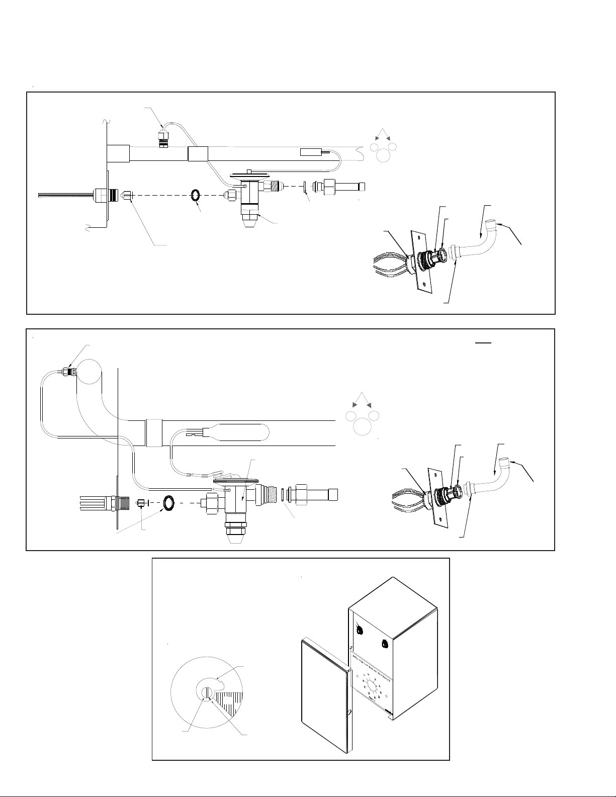
EXP ANSION VALVE KITS
1/4 FLARE CONNECTION
BULB TO BE LOCATED
AT 10 OR 2 O'CLOCK
For Applications requiring
a field installed access fitting
EVAPORATOR COIL
EVAPORATOR COIL
1/4' FLARE
CONNECTION
SEAL SUPP L IE D W/ KIT
REMOVE BEFORE INSTALLI NG EXP ANS IO N VALVE
SUCTION LINE
BULB
EXPANSION VALVE
SUCTION LINE
EXPAN SION VALVE
BULB
SEAL SUPPLIED W/ KIT
BULB TO BE LOCATED
AT 10 OR 2 O'CLOCK
DISTRIBUTOR
BODY
For Applications not requiring
a field installed access fitting
DISTRIBUTOR
BODY
7/8" NUT
PISTON
SEAL
PISTON
SEAL
TAILPIECE
3/8"SWEAT
TAILPIECE
3/8"SWEAT
SEAL SUPPLIED W/ KIT
7/8" NUT
SEAL SUPPLIED W/ KIT
REMOVE BEFORE
INSTALLING
EXPANSION VALVE
OT/EHR18-60
OUTDOOR THERMOSTAT &
EMERGENCY HEAT RELA Y
OT18-60
Thermostat
DEAD
DIAL
45º
Dial
COLD
WARM
Set Point
Indicato r
Mark
(Shown @ Oº F)
(Turn Clockwise)
(Turn Counterclockwise)
315º
Set Point
djustmen t
Screw
20
Page 21
ACCESSORIES
Y
Wire Nut
FSK01A
FREEZE THERMOSTAT
KIT
Y
k
c
a
l
B
k
c
a
l
B
Wire Nut
Y
Install L ine
Thermostat
Here
ASC01A
ANTI-SHORT -CYCLE CONTROL KIT
SHOR T CYCLE
Y1Y2R1
R2
PROTECTOR
Install Line
Thermostat
Here
B
l
a
c
B
l
Wire Nut
Wire Nut
Y
k
a
c
k
Y
ELLOW 1
CONTACTOR
BLACK 1
T2 T1
L2
L1
BLACK 1
Y
THERMOSTAT
WIRE
C
UNIT
TERMINAL
BOARD
21
Page 22
ACCESSORIES
COIL MODEL TX2N4 TXV KIT TX3N4 TXV KIT TX5N4 TXV KIT FSK01A FREEZE PROTECTION KIT
CA*F18246*
CA*F30306* XX
CA*F36426* XX X
CHPF18246* XX
CHPF30306* XX
CHPF36426* XX
CSCF1824N6*
CSCF303N6* XX
CSCF3642N6* XX X
COIL ACCESSORIES
XX X
XX
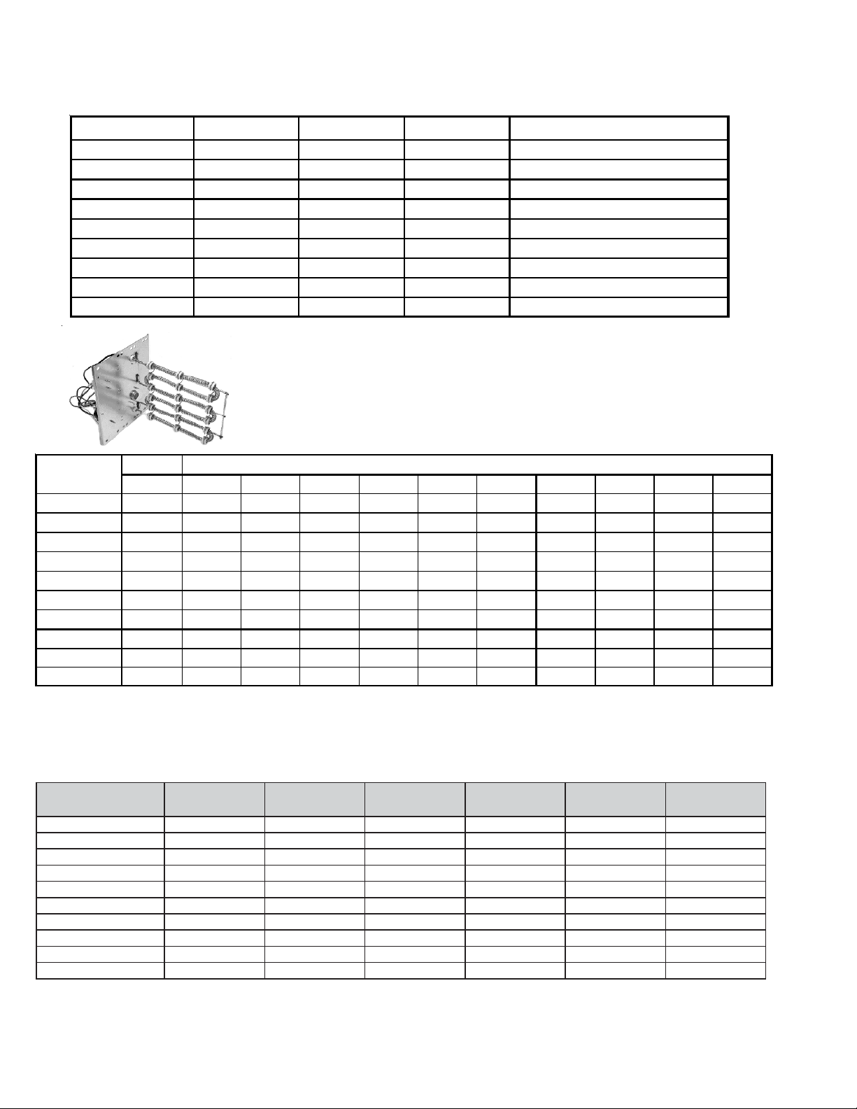
HKR SERIES ELECTRIC HEA T KITS
ELECTRIC HEAT KIT APPLICATIONS - MBR & MBE
BLOWER
MBR0800AA-1AA - X X X X X
MBR1200AA-1AA- XXXXXXXXXX
MBR1600AA-1AA- XXXXXXXXXX
MBR2000AA-1AA- XXXXXXXXXX
MBE1200AA-1AA - - - - X X X - - - MBE1600AA-1AA-----XX---MBE2000AA-1AA - - - - - X X X - - MBE1200AA-1BA - X X X X X X - - - MBE1600AA-1BA - X X X X X X - - - MBE2000AA-1BA- XXXXXXX- - -
X = Allowable combinations
- = Restricted combinations
NO HEAT HKR-03* HKR05-(C)' HKR-06* HKR-08(C)* HKR-10(C)* HKR-15(C)* HKR-20(C)* HKR-21(C)* ^HKR3-15* ^HKR3-20A
^ = Circuit 1: Single Phase for Air Handler Motor * = Revision level that my or may not be designated
Circuit 2: 3-Phase for HKR3 Heater Kits C = Circuit Breaker option
ELECTRIC HEAT KIT
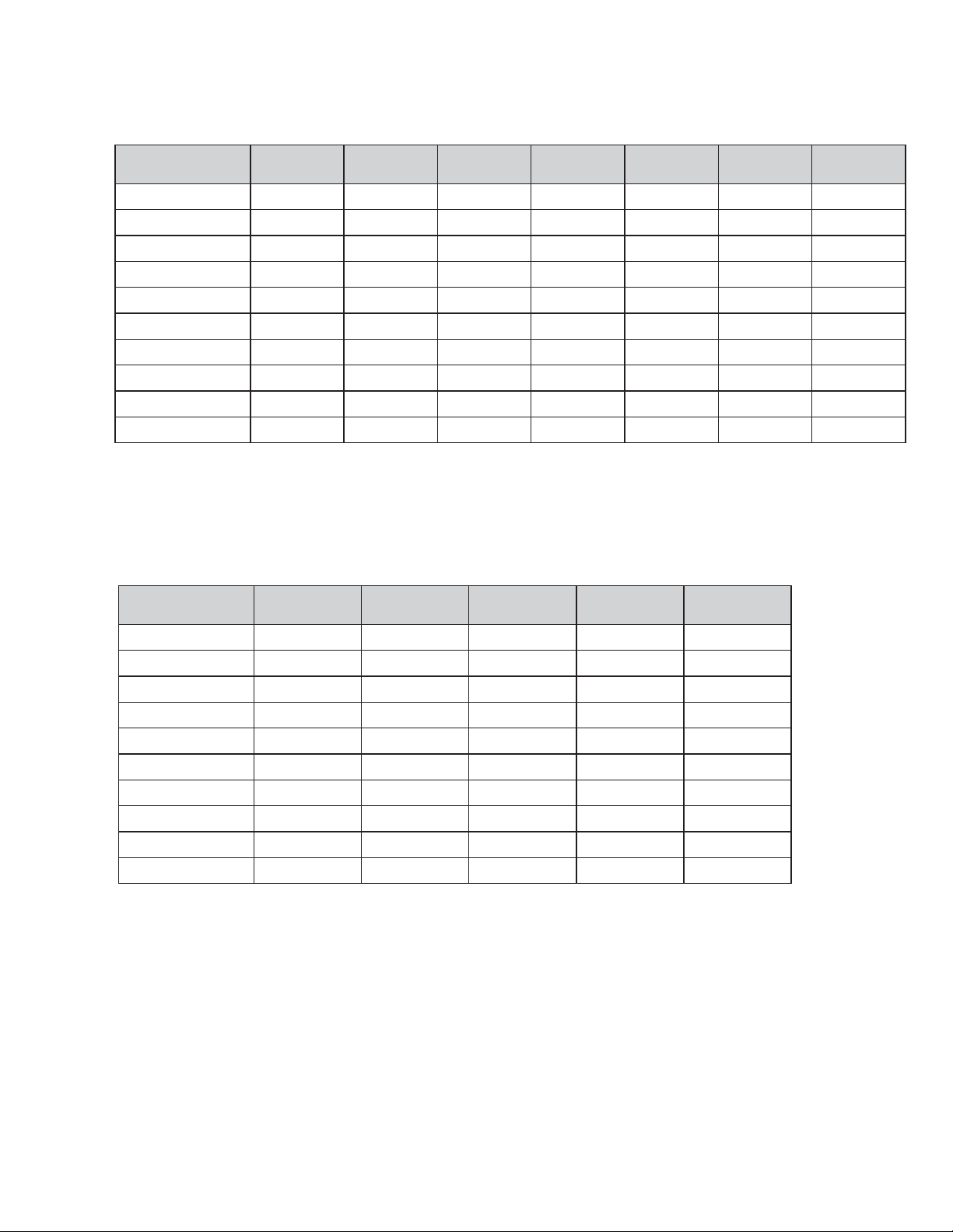
ELECTRIC HEAT KIT APPLICATIONS - ARPF
ARPF1824
1/16
HKR-03* X X X X X X
HKR-05*, HKR-05C* X X X X X X
HKR-06* X X X X X X
HKR-08*, HKR-08C* X
HKR-10*, HKR-10C* X
HKR-15C* X
1
1
2
HKR-20C* X
HKR-21C* X
^ HKR3-15* X
^ HKR3-20* X
* Revision level that may or may not be designated
C Circuit breaker option
^ Heat kit requires three-phase power supply
ARPF1931
1/16
1
X
1
X
2
X
ARPF3030
1/16
ARPF3642
1/16
ARPF3743
1/16
ARPF4860
1/16
XXXX
1
X
2
X
2
2
2
2
¹ Air handler must either be on medium or high speed
² Air handler must be on high speed
³ For static pressure of 0.6 or higher, air handler must be on
XXX
3
X
3
X
3
X
3
X
3
X
3
X
3
X
3
X
3
X
3
X
X
X
X
X
X
22
Page 23
ACCESSORIES
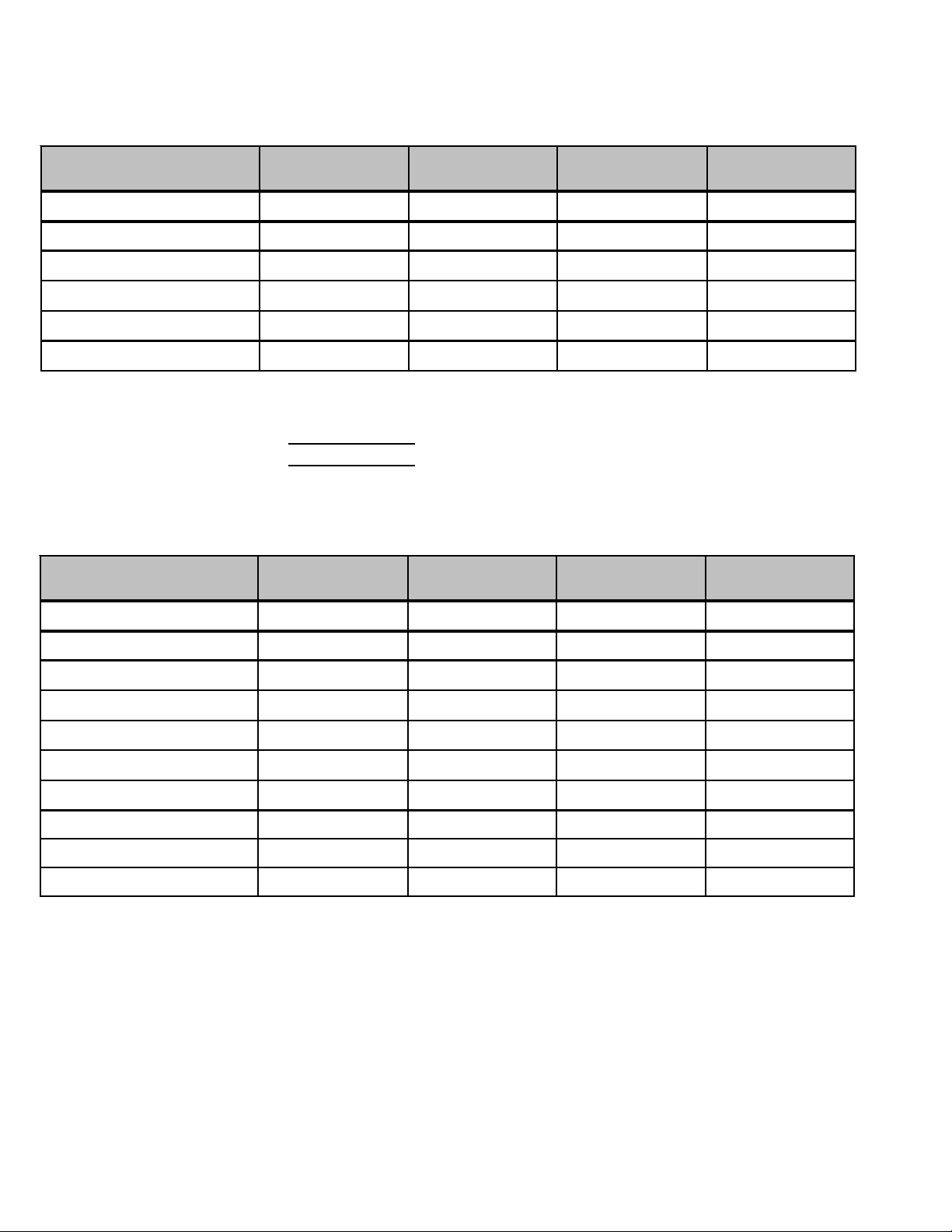
ELECTRIC HEAT KIT APPLICATIONS - ARUF
ARUF1729
1/16
ARUF1824
1/16
ARUF1931
1/16
ARUF3030
1/16
ARUF3642
1/16
ARUF3743
1/16
ARUF4860
1/16
HKR-03* XXXXXXX
HKR-05*, HKR-05C* XXXXXXX
HKR-06* XXXXXXX
HKR-08*, HKR-08C* X
HKR-10*, HKR-10C* X
HKR-15C* X
1
1
2
HKR-20C* X
HKR-21C* X
^ HKR3-15* X
^ HKR3-20* X
* Revision level that may or may not be designated
C Circuit breaker option
^ Heat kit requires three-phase power supply
1
Air handler must either be on medium or high speed
2
Air handler must be on high speed
3
For static pressure of 0.6 or higher, air handler must be on medium or high speed
ARUF024-
00A1A
1
X
1
X
2
X
ARUF032-
00A1B
1
X
1
X
2
X
ARUF042-
00A1B
XXXX
1
X
2
X
2
2
2
2
ARUF049-
00A1B
XXX
3
X
3
X
3
X
3
X
3
X
3
X
3
X
3
X
3
X
3
X
ARUF061-
00A1B
HKR-03* XXXXX
HKR-05*, HKR-05C* XXXXX
HKR-06* XXXXX
HKR-08*, HKR-08C* X X
HKR-10*, HKR-10C* X
1
HKR-15C* X
1
1
X
2
HKR-20C* X
HKR-21C* X
^ HKR3-15* X
^ HKR3-20* X
XXX
1
X
2
X
2
2
2
2
XX
3
X
3
X
3
X
3
X
3
X
X
X
X
X
X
X
X
X
X
X
* Revision level that may or may not be designated
C Circuit breaker option
^ Heat kit requires three-phase power supply
1
Air handler must either be on medium or high speed
2
Air handler must be on high speed
3
For static pressure of 0.6 or higher, air handler must be on medium or high speed
23
Page 24
ACCESSORIES
ELECTRIC HEAT KIT APPLICATIONS - AEPF
AEPF183016 AEPF303616 AEPF313716 AEPF426016
HKR-05*, HKR-05C* X X
HRK-08*, HKR-08C X X X
HKR-10*, HKR-10C
1
X
HKR-15C*
HKR-20C*
HKR-21C
*
Revision level that may or may not be designated
C Circuit Breaker option
1
This heater kit can be used ONLY for 1000 CFM or higher applications
2
This heater kit can be used ONLY for 1200 CFM or higher applications
XXX
1
X
1
X
X
2
X
2
X
ELECTRIC HEAT KIT APPLICATIONS - ASPF
ASPF183016 ASPF303616 ASPF313716 ASPF426016
HKR-03* XXXX
HKR-05*, HKR-05C* X X X X
HKR-06* XXXX
HRK-08*, HKR-08C*
HKR-10*, HKR-10C*
HKR-15C*
HKR-20C*
HKR-21C*
+HKR3-15*
+HKR3-20*
*
Revision level that may or may not be designated
C Circuit Breaker option
+ Heat kit requires 3-phase power supply
1
Air handler must be on speed tap 2, 3, 4 or 5
2
Air handler must be on speed tap 4 or 5
3
Air handler must be on speed tap 3, 4 or 5
1
X
1
X
2
X
2
X
1
X
1
X
2
X
2
X
2
X
2
X
2
X
1
X
1
X
2
X
2
X
2
X
2
X
2
X
X
X
1
X
1
X
1
X
1
X
1
X
24
Page 25

PRODUCT DESIGN
This section gives a basic description of cooling unit operation, its various components and their basic operation.
Ensure your system is properly sized for heat gain and loss
according to methods of the Air Conditioning Contractors
Association (ACCA) or equivalent.
CONDENSING UNIT
The condenser air is pulled through the condenser coil by a
direct drive propeller fan. This condenser air is then discharged out of the top of the cabinet. These units are
designed for free air discharge, so no additional resistance,
like duct work, shall be attached.
The suction and liquid line connections on present models
are of the sweat type for field piping with refrigerant type
copper. Front seating valves are factory installed to accept
the field run copper. The total refrigerant charge for a normal
installation is factory installed in the condensing unit.
GSX, GSZ, ASX, ASZ, SSX, SSZ and DSX, DSZ models are
available in 1 1/2 through 5 ton sizes and use R-410A
refrigerant. They are designed for 208/230 volt single phase
applications.
ASX, ASZ, DSX and DSZ R-410A model units use the
Copeland Scroll "Ultratech" Series compressors which are
specifically designed for R-410A refrigerant. These units also
have Copeland
GSX, GSZ, SSX and SSZ R-410A model units use the
Copeland Scroll "Ultratech" Series compressors which are
specifically designed for R-410A refrigerant.
There are a number of design characteristics which are
different from the traditional reciprocating and/or scroll compressors.
"Ultractech" Series scroll compressors will not have a discharge thermostat. Some of the early model scroll compressors required discharge thermostat.
"Ultratech" Series scroll compressors use "POE" or
polyolester oil which is NOT compatible with mineral oil
based lubricants like 3GS. "POE" oil must be used if
additional oil is required.
®
ComfortAlert diagnostics.
COILS AND BLOWER COILS
MBR/MBE blower cabinets are designed to be used as a twopiece blower and coil combination. MBR/MBE blower sections can be attached to cased evaporator coil. This twopiece arrangement allows for a variety of mix-matching
possibilities providing greater flexibility. The MBE blower
cabinet uses a variable speed motor that maintains a constant airflow with a higher duct static.
It is approved for applications with cooling coils of up to 0.8
inches W.C. external static pressure and includes a feature
that allows airflow to be changed by +15%. The MBR blower
cabinet uses a PSC motor. It is approved for applications with
cooling coils of up to 0.5 inches W.C. external static pressure.
The MBR/MBE blower cabinets with proper coil matches can
be positioned for upflow, counterflow, horizontal right or
horizontal left operation. All units are constructed with R-4.2
insulation. In areas of extreme humidity (greater than 80%
consistently), insulate the exterior of the blower with insulation having a vapor barrier equivalent to ductwork insulation,
providing local codes permit.
The CAPX/CHPX coils are equipped with a thermostatic
expansion valve that has a built-in internal check valve for
refrigerant metering. The CACF/CAPF/CHPF coils are
equipped with a fixed restrictor orifice.
The coils are designed for upflow, counterflow or horizontal
application, using two-speed direct drive motors on the
CACF/CAPF/CHPX models and BPM (Brushless Permanent
Magnet) or ECM motors on the MBE models.
25
Page 26

PRODUCT DESIGN
The ASX [16 & 18], ASZ [16 & 18], DSX16 and DSZ16 series
split system units use a two-stage scroll compressor. The
two-step modulator has an internal unloading mechanism
that opens a bypass port in the first compression pocket,
effectively reducing the displacement of the scroll. The
opening and closing of the bypass port is controlled by an
internal electrically operated solenoid.
The ZPS/ZRS two-step modulated scroll uses a single step
of unloading to go from full capacity to approximately 67%
capacity. A single speed, high efficiency motor continues to
run while the scroll modulates between the two capacity
steps.
FIGURE A
A scroll is an involute spiral which, when matched with a
mating scroll form as shown, generates a series of crescent
shaped gas pockets between the two members.
During compression, one scroll remains stationary (fixed
scroll) while the other form (orbiting scroll) is allowed to orbit
(but not rotate) around the first form.
As this motion occurs, the pockets between the two forms
are slowly pushed to the center of the two scrolls while
simultaneously being reduced in volume. When the pocket
reaches the center of the scroll form, the gas, which is now
at a high pressure, is discharged out of a port located at the
center.
During compression, several pockets are being compressed
simultaneously, resulting in a very smooth process. Both the
suction process (outer portion of the scroll members) and the
discharge process (inner portion) are continuous.
Some design characteristics of the Compliant Scroll compressor are:
• Compliant Scroll compressors are more tolerant of liquid
refrigerant.
NOTE: Even though the compressor section of a Scroll
compressor is more tolerant of liquid refrigerant, continued floodback or flooded start conditions may wash oil
from the bearing surfaces causing premature bearing
failure.
• Compliant Scroll compressors use white oil which is
compatible with 3GS. 3GS oil may be used if additional
oil is required.
• Compliant scroll compressors perform "quiet" shutdowns
that allow the compressor to restart immediately without
the need for a time delay. This compressor will restart
even if the system has not equalized.
NOTE: Operating pressures and amp draws may differ
from standard reciprocating compressors. This information can be found in the unit's Technical Information
Manual.
26
Page 27

PRODUCT DESIGN
CAPACITY CONTROL
During the compression process, there are several pockets
within the scroll that are compressing gas. Modulation is
achieved by venting a portion of the gas in the first suction
pocket back to the low side of the compressor thereby
reducing the effective displacement of the compressor. See
Figure A. Full capacity is achieved by blocking these vents,
increasing the displacement to 100%. A solenoid in the
compressor, controlled by an external 24-volt ac signal,
moves the slider ring that covers and uncovers these vents.
The vent covers are arranged in such a manner that the
compressor operates somewhere around 67% capacity when
the solenoid is not energized and 100% capacity when the
solenoid is energized. The loading and unloading of the two
step scroll is done “on the fly” without shutting off the motor
between steps. See Figure B below. The unloaded mode
default was chosen for two reasons:
1. It is expected that the majority of run hours will be in the
low capacity, unloaded mode.
2. It allows a simple two-stage thermostat to control capacity through the second stage in both cooling and possibly
heating if desired.
UNLOADER SOLENOID
A nominal 24-volt direct current coil activates the internal
unloader solenoid. The input control circuit voltage must be
18 to 28 volt ac. The coil power requirement is 20 VA. The
external electrical connection is made with a molded plug
assembly. This plug is connected to the Comfort Alert
Module which contains a full wave rectifier to supply direct
current to the unloader coil.
FIGURE B
27
Page 28

SYSTEM OPERA TION
COOLING
The refrigerant used in the system is R-410A. It is a clear,
colorless, non-toxic and non-irritating liquid. R-410A is a
50:50 blend of R-32 and R-125. The boiling point at atmospheric pressure is -62.9°F.
A few of the important principles that make the refrigeration
cycle possible are: heat always flows from a warmer to a
cooler body. Under lower pressure, a refrigerant will absorb
heat and vaporize at a low temperature. The vapors may be
drawn off and condensed at a higher pressure and temperature to be used again.
The indoor evaporator coil functions to cool and dehumidify
the air conditioned spaces through the evaporative process
taking place within the coil tubes.
NOTE: The pressures and temperatures shown in the
refrigerant cycle illustrations on the following pages are for
demonstration purposes only. Actual temperatures and pressures are to be obtained from the "Expanded Performance
Chart".
Liquid refrigerant at condensing pressure and temperatures,
(270 psig and 122°F), leaves the outdoor condensing coil
through the drier and is metered into the indoor coil through
the metering device. As the cool, low pressure, saturated
refrigerant enters the tubes of the indoor coil, a portion of the
liquid immediately vaporizes. It continues to soak up heat and
vaporizes as it proceeds through the coil, cooling the indoor
coil down to about 48°F.
Heat is continually being transferred to the cool fins and tubes
of the indoor evaporator coil by the warm system air. This
warming process causes the refrigerant to boil. The heat
removed from the air is carried off by the vapor.
As the vapor passes through the last tubes of the coil, it
becomes superheated. That is, it absorbs more heat than is
necessary to vaporize it. This is assurance that only dry gas
will reach the compressor. Liquid reaching the compressor
can weaken or break compressor valves.
The compressor increases the pressure of the gas, thus
adding more heat, and discharges hot, high pressure superheated gas into the outdoor condenser coil.
In the condenser coil, the hot refrigerant gas, being warmer
than the outdoor air, first loses its superheat by heat transferred from the gas through the tubes and fins of the coil. The
refrigerant now becomes saturated, part liquid, part vapor and
then continues to give up heat until it condenses to a liquid
alone. Once the vapor is fully liquefied, it continues to give up
heat which subcools the liquid, and it is ready to repeat the
cycle.
HEATING
The heating portion of the refrigeration cycle is similar to the
cooling cycle. By energizing the reversing valve solenoid coil,
the flow of the refrigerant is reversed. The indoor coil now
becomes the condenser coil, and the outdoor coil becomes
the evaporator coil.
The check valve at the indoor coil will open by the flow of
refrigerant letting the now condensed liquid refrigerant bypass the indoor expansion device. The check valve at the
outdoor coil will be forced closed by the refrigerant flow,
thereby utilizing the outdoor expansion device.
The restrictor orifice used with the CA*F, CHPF and CH**FCB
coils will be forced onto a seat when running in the cooling
cycle, only allowing liquid refrigerant to pass through the
orifice opening. In the heating cycle, it will be forced off the
seat allowing liquid to flow around the restrictor. A check valve
is not required in this circuit.
COOLING CYCLE
When the contacts of the room thermostat close making
terminals R to Y & G, the low voltage circuit of the transformer
is completed. Current now flows through the magnetic holding coils of the compressor contactor (CC) and fan relay
(RFC).
This draws in the normally open contact CC, starting the
compressor and condenser fan motors. At the same time,
contacts RFC close, starting the indoor fan motor.
When the thermostat is satisfied, it opens its contacts,
breaking the low voltage circuit, causing the compressor
contactor and indoor fan relay to open, shutting down the
system.
If the room thermostat fan selector switch should be set on
the "on" position, then the indoor blower would run continuous
rather than cycling with the compressor.
GSZ, ASZ, SSZ and DSZ models energize the reversing valve
thorough the "O" circuit in the room thermostat. Therefore,
the reversing valve remains energized as long as the thermostat subbase is in the cooling position. The only exception to
this is during defrost.
28
Page 29

SYSTEM OPERA TION
DEFROST CYCLE
The defrosting of the outdoor coil is jointly controlled by the
defrost control board and the defrost thermostat.
Solid State Defrost Control
During operation the power to the circuit board is controlled
by a temperature sensor, which is clamped to a feeder tube
entering the outdoor coil. Defrost timing periods of 30, 60, or
90 minutes may be selected by connecting the circuit board
jumper to 30, 60, or 90 respectively. Accumulation of time for
the timing period selected starts when the sensor closes
(approximately 31° F), and when the room thermostat calls
for heat. At the end of the timing period, the unit’s defrost
cycle will be initiated provided the sensor remains closed.
When the sensor opens (approximately 75° F), the defrost
cycle is terminated and the timing period is reset. If the
defrost cycle is not terminated due to the sensor temperature, a ten minute override interrupts the unit’s defrost period.
TEST
90
60
30
JUMPER WIRE
A
CY W2 R R DFT
DF2
DF1
HEATING CYCLE
The reversing valve on the GSZ, SSZ, ASZ and DSZ models
is energized in the cooling cycle through the "O" terminal on
the room thermostat.
These models have a 24 volt reversing valve coil. When the
thermostat selector switch is set in the cooling position, the
"O" terminal on the thermostat is energized all the time.
Care must be taken when selecting a room thermostat. Refer
to the installation instructions shipped with the product for
approved thermostats.
29
Page 30

SYSTEM OPERA TION
COOLING CYCLE
Reversing Valve
(Energized)
Indoor
Coil
HEATING CYCLE
Outdoor
Coil
Accumulator
Thermostatic
Expansion
Valve
Bi-Flow
Filter Dryer
Check Valve
30
Indoor
Coil
Reversing Valve
(De-Energized)
Outdoor
Coil
Accumulator
Thermostatic
Expansion
Valve
Bi-Flow
Filter Dryer
Check Valve
Page 31

SYSTEM OPERA TION
EXPANSION VALVE/CHECK VALVE ASSEMBLY
IN COOLING OPERATION
Most expansion valves used in current Amana® Brand Heat Pump products
use an internally checked expansion valve.
This type of expansion valve does not require an external check valve as shown above.
However, the principle of operation is the same.
RESTRICTOR ORIFICE ASSEMBLY
IN COOLING OPERATION
EXPANSION VALVE/CHECK VALVE ASSEMBLY
IN HEATING OPERATION
RESTRICTOR ORIFICE ASSEMBLY
IN HEATING OPERATION
In the cooling mode, the orifice is pushed into its
seat, forcing refrigerant to flow through the metered
hole in the center of the orifice.
In the heating mode, the orifice moves back off its
seat, allowing refrigerant to flow unmetered around
the outside of the orifice.
31
Page 32

SYSTEM OPERA TION
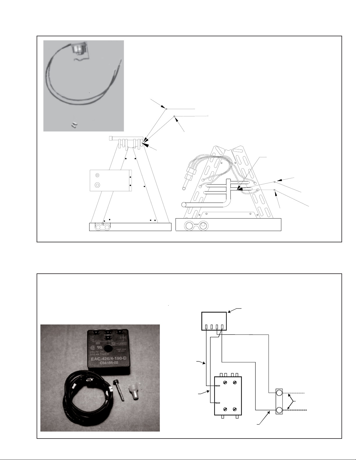
AFE18-60A CONTROL BOARD
DESCRIPTION
The AFE18 control is designed for use in heat pump applications where the indoor coil is located above/downstream of a
gas or fossil fuel furnace. It will operate with single and two
stage heat pumps and single and two stage furnaces. The
AFE18 control will turn the heat pump unit off when the
furnace is turned on. An anti-short cycle feature is also
incorporated which initiates a 3 minute timed off delay when
the compressor goes off. On initial power up or loss and
restoration of power, this 3 minute timed off delay will be
initiated. The compressor won’t be allowed to restart until the
3 minute off delay has expired. Also included is a 5 second
de-bounce feature on the “Y, E, W1 and O” thermostat inputs.
These thermostat inputs must be present for 5 seconds
before the AFE18 control will respond to it.
An optional outdoor thermostat, OT18-60A, can be used with
the AFE18 to switch from heat pump operation to furnace
operation below a specific ambient temperature setting, i.e.
break even temperature during heating. When used in this
manner, the “Y” heat demand is switched to the “W1” input
to the furnace by the outdoor thermostat and the furnace is
used to satisfy the first stage “Y” heat demand. On some
controls, if the outdoor thermostat fails closed in this position
during the heating season, it will turn on the furnace during
the cooling season on a “Y” cooling demand. In this
situation, the furnace produces heat and increases the
indoor temperature thereby never satisfying the cooling
demand. The furnace will continue to operate and can only
be stopped by switching the thermostat to the off position or
removing power to the unit and then replacing the outdoor
thermostat. When the AFE18 receives a “Y” and “O”
input from the indoor thermostat, it recognizes this as a
cooling demand in the cooling mode. If the outdoor thermostat is stuck in the closed position switching the “Y” demand
to the “W1” furnace input during the cooling mode as
described above, the AFE18 won’t allow the furnace to
operate. The outdoor thermostat will have to be replaced to
restore the unit to normal operation.
HIGH VOLTAGE!
Disconnect ALL power before servicing
or installing. Multiple power sources
may be present. Failure to do so may
cause property damage, personal injury
or death.
32
Page 33

TROUBLESHOOTING CHART
COOLING/HP ANALYSIS CHART
Com p laint
POSSIBLE CAUSE
DOTS IN ANALYSIS
GUIDE INDICATE
"POS SIBL E CAUSE"
Pow er Failure
Blow n Fuse
Unbalanced Power, 3PH
Loose Connection
Shorted or Broken Wires
Open Fan Overload
Faulty Thermostat
Faulty Transformer
Shorted or Open Capacitor
Internal Compressor Overload Open
Shorted or Grounded Compressor
Compre s sor Stuc k
Faulty Compressor Contactor
Faulty Fan Relay
Open Control Circuit
Low Voltage
Faulty Evap. Fan Motor
Shorted or Grounded Fan Motor
Improper Cooling Anticipator
Shortage of Refrigerant
Restricted Liquid Line
Open Element or Limit on Elec. Heater
Dirty Air Filter
Dirty Indoor Coil
Not enough air across Indoor Coil
Too much air across Indoor Coil
Overcharge of Refrigerant
Dirty Outdoor Coil
Noncondensibles
Recirculation of Conden sing Air
Infiltration of Outdoor Air
Improperly Lo cated Thermostat
Air Flow Unbalanced
System Undersized
Broken Internal Parts
Broken Valves
Ineff icient Compressor
Wrong Type Expansion Valve
Expansion Device Restricted
Oversized Expansion Valve
Undersized Expansion Valve
Expansion Valve Bulb Loose
Inoperative Expansion Valve
Loose Hold-down Bolts
Faulty Reversing Valve
Faulty Defrost Control
Faulty Defrost Thermostat
Flowrator Not Seating Properly
No Cooling
SYMPTOM
System will not start
Compressor will not start - fan runs
Comp. and Cond. Fan will not start
Evaporator fan will not start
Condenser fan will not start
Compressor runs - goes off on overload
Compressor cycles on overload
Unsatis facto r y
Cooling/Heating
System runs continuously - little cooling/htg
Too cool and then too warm
•
•••
•••
•••
••••••
••
••• •
••
•••••
•
••
•••
•••
•
•
•••
••
••
••
••
•• •• •
♦♦
••• •
••• •
••• •
•• •
•• •
••
•• •
•••
••
••
••
•• ••
•
••• • ••
••• • •• •
••
••• • •
•• •
•
•
• Cooling or Heating Cycle (Hea t Pum p)
•••
System
Ope rating
Pressures
Not cool enough on warm days
Certain areas too cool, others too warm
Compressor is noisy
System runs - blows cold air in heating
Unit will not terminate defrost
Unit will not defrost
Low suction pressure
Low head pressure
High suction pressure
High head pressure
♦
♦
♦
♦
♦
♦
♦
•
♦
••
♦
♦
••
♦
♦
♦
•
••
•
•
♦
••
•
♦♦♦ ♦♦♦
♦♦♦♦♦ ♦
♦♦♦♦♦♦♦
Heating Cycle Only (Heat Pump)
♦
Test Method
Re medy
See Service Procedure Ref.
Test Voltage S-1
Inspect Fuse Size & Type S-1
Test Voltage S-1
Inspe ct Connec tion - Tighten S-2, S-3
Test Circuits With Ohmmeter S-2, S-3
Test Continuity of Ov erload S-17A
Test Continuity of Thermostat & Wiring S-3
Check Control Circuit w ith Voltmeter S-4
Test Capacitor S-15
Test Continuity of Ov erload S-17A
Test Motor Windings S-17B
Use Tes t Cord S-17D
Test Continuity of Coil & Contacts S-7, S-8
Test Continuity of Coil And Contacts S-7
Test Control Circuit w ith Voltmeter S-4
Test Voltage S-1
Repair or Replace S-16
Test Motor Windings S-16
Check Resistance of Anticipator S-3B
Test For Leaks, Add Refrigerant S-101,103
Remove Restriction, Replace Restricted Part S-112
Test Heater Element and Controls S-26,S-27
Inspect Filter-Clean or Replace
Inspect Coil - Clean
Check Blower Speed, Duct Static Press, Filter S-200
Reduce Blow er Spe ed S-200
Recov er Part of Charge S-113
Inspect Coil - Clean
Recov er Charge, Evac u ate , Rech a rge S-114
Remove Obstruction to Air Flow
Check Window s , Doors, Vent Fans , Etc.
Relocate Thermostat
Readjust Air Volume Dampers
Refigure Cooling Load
Replace Compresso r S-115
Test Compressor Efficiency S-104
Test Compressor Efficiency S-104
Replace V alv e S-110
Remove Restriction or Replace Expansion Device S-110
Replace V alv e
Replace V alv e
Tighten Bulb Bracket S-105
Check Valve Operation S-110
Tigh ten B olts
Replace Valve or Solenoid S-21, 122
Test Contro l S-24
Test Defrost Thermostat S-25
Check Flowrator & Seat or Replace Flowrator S-111
33
Page 34

SERVICING
S-1 Checking Voltage .......................................... 35
S-2 Checking Wiring............................................ 35
S-3 Checking Thermostat, Wiring & Anticipator .. 35
S-3A Thermostat & Wiring ..................................... 35
S-3B Cooling Anticipator........................................ 36
S-3C Heating Anticipator........................................ 36
S-3D Checking Encoded Thermostats ................... 36
S-4 Checking Transformer & Control Circuit ....... 37
S-5 Checking Cycle Protector ............................. 37
S-6 Checking Time Delay Relay ..........................37
S-7 Checking Contactor and/or Relays................ 38
S-8 Checking Contactor Contacts ....................... 38
S-9 Checking Fan Relay Contact ........................ 38
S-10 Copeland Comfort™ Alert Diagnositics ......... 39
S-11 Checking Loss of Charge Protector............... 41
S-12 Checking High Pressure Control ................... 41
S-13 Checking Low Pressure Control .................... 41
S-15 Checking Capacitor....................................... 41
S-15A Resistance Check......................................... 42
S-15B Capacitance Check....................................... 4 2
S-16A Checking Fan & Blower Motor
Windings (PSC Motors) ............................... 43
S-16B Checking Fan & Blower Motor (ECM Motors) 4 3
S-16C Checking ECM Motor Windings .................... 46
S-16D ECM CFM Adjustments................................ 46
S-16E Blower Performance Data.............................. 48
S-16F Checking GE X13™ Motors .......................... 48
S-17 Checking Compressor Windings ................... 49
S-17A Resistance Test............................................ 49
S-17B Ground Test .................................................. 49
S-17C Unloader Test................................................ 50
S-17D Operation Test .............................................. 50
S-18 Testing Crankcase Heater (optional item) ..... 51
S-21 Checking Reversing Valve and Solenoid........ 51
S-24 Testing Defrost Control.................................. 51
S-25 Testing Defrost Thermostat ........................... 51
S-26 Checking Heater Limit Control(s) .................. 52
S-27 Checking Heater Elements ............................... 52
S-40 MBR/ARUF Electronic Blower Time Delay
with Single Stage Air Conditioners
& Heat Pumps .................................................. 52
S-41 MBE/AEPF with GSX, SSX, ASX, DSX
Air Conditioners ................................................ 54
S-41A MBE/AEPF with GSZ, SSZ, ASZ
Heat Pumps...................................................... 5 5
S-60 Electric Heater (optional item)........................... 58
S-61A Checking Heater Limit Control(S)...................... 59
S-61B Checking Heater Fuse Line............................... 59
S-62 Checking Heater Elements ............................... 59
S-100 Refrigeration Repair Practice.............................60
S-101 Leak Testing ..................................................... 60
S-102 Evacuation ........................................................ 60
S-103 Charging............................................................ 61
S-104 Checking Compressor Efficiency ...................... 6 2
S-105A Piston Chart - ASX13, GSX13, SSX14,
ASX14, ASZ13, GSZ13 Units............................ 63
S-105B Thermostatic Expansion Valve .......................... 63
S-106 Overfeeding ....................................................... 66
S-107 Underfeeding ..................................................... 66
S-108 Superheat ......................................................... 66
S-109 Checking Subcooling ........................................ 66
S-109A Two Speed Application...................................... 6 7
S-109B Heat Pump Heating Mode ................................. 67
S-110 Checking Expansion Valve Operation ............... 6 7
S-111 Fixed Orifice Restriction Devices ...................... 67
S-112 Checking Restricted Liquid Line........................ 68
S-113 Refrigerant Overcharge ...................................... 68
S-114 Non-condensables ............................................ 68
S-115 Compressor Burnout ......................................... 68
S-120 Refrigerant Piping.............................................. 69
S-202 Duct Static Pressure
& Static Pressure Drop Across Coils ................ 71
S-203 Air Handler External Static ............................... 71
S-204 Coil Static Pressure Drop ................................. 72
HIGH VOLTA GE!
Disconnect ALL power before servicing or installing. Multiple power sources may be present. Failure to
do so may cause property damage, personal injury or death.
34
Page 35

SERVICING
S-1 CHECKING VOLTAGE
1. Remove outer case, control panel cover, etc., from unit
being tested.
With power ON:
WARNING
Line Voltage now present.
2. Using a voltmeter, measure the voltage across terminals
L1 and L2 of the contactor for the condensing unit or at the
field connections for the air handler or heaters.
3. No reading - indicates open wiring, open fuse(s) no power
or etc., from unit to fused disconnect service. Repair as
needed.
4. With ample voltage at line voltage connectors, energize
the unit.
5. Measure the voltage with the unit starting and operating,
and determine the unit Locked Rotor Voltage. NOTE: If
checking heaters, be sure all heating elements are
energized.
Locked Rotor Voltage is the actual voltage available at
the compressor during starting, locked rotor, or a stalled
condition. Measured voltage should be above minimum
listed in chart below.
To measure Locked Rotor Voltage attach a voltmeter to
the run "R" and common "C" terminals of the compressor,
or to the T1 and T2 terminals of the contactor. Start the unit
and allow the compressor to run for several seconds, then
shut down the unit. Immediately attempt to restart the
unit while measuring the Locked Rotor Voltage.
6. Lock rotor voltage should read within the voltage tabulation as shown. If the voltage falls below the minimum
voltage, check the line wire size. Long runs of undersized
wire can cause low voltage. If wire size is adequate, notify
the local power company in regard to either low or high
voltage.
UNIT SUPPLY VOLTAGE
VOLTAGE MIN. MAX.
460 437 506
208/230 198 253
NOTE: When operating electric heaters on voltages other
than 240 volts, refer to the System Operation section on
electric heaters to calculate temperature rise and air flow.
Low voltage may cause insufficient heating.
S-2 CHECKING WIRING
HIGH VOLTAGE!
Disconnect A LL power befor e servicing
or installing. Multiple power sources
may be pres ent. Fai lure to do so ma y
caus e pro pe r ty dam a ge, pe r son al in ju r y
or death.
1. Check wiring visually for signs of overheating, damaged
insulation and loose connections.
2. Use an ohmmeter to check continuity of any suspected
open wires.
3. If any wires must be replaced, replace with comparable
gauge and insulation thickness.
S-3 CHECKING THERMOSTAT, WIRING, AND
ANTICIPATOR
THERMO ST AT W I RE SIZI NG CHART
LENGTH OF RUN
25 fe et 18
50 fe et 16
75 fe et 14
100 fe et 14
125 fe et 12
150 fe et 12
M IN. COPPER WI RE
GAUGE (AWG)
S-3A THERMOSTAT AND WIRING
WARNING
Line Voltage now present.
With power ON, thermostat calling for cooling
1. Use a voltmeter to check for 24 volts at thermostat wires
C and Y in the condensing unit control panel.
2. No voltage indicates trouble in the thermostat, wiring or
external transformer source.
3. Check the continuity of the thermostat and wiring. Repair
or replace as necessary.
Indoor Blower Motor
With power ON:
WARNING
Line Voltage now present.
1. Set fan selector switch at thermostat to "ON" position.
2. With voltmeter, check for 24 volts at wires C and G.
3. No voltage indicates the trouble is in the thermostat or
wiring.
35
Page 36

SERVICING
4. Check the continuity of the thermostat and wiring. Repair
or replace as necessary.
Resistance Heaters
1. Set room thermostat to a higher setting than room
temperature so both stages call for heat.
2. With voltmeter, check for 24 volts at each heater relay.
Note: BBA/BBC heater relays are DC voltage.
3. No voltage indicates the trouble is in the thermostat or
wiring.
4. Check the continuity of the thermostat and wiring. Repair
or replace as necessary.
NOTE: Consideration must be given to how the heaters are
wired (O.D.T. and etc.). Also safety devices must be checked
for continuity.
S-3B COOLING ANTICIPATOR
The cooling anticipator is a small heater (resistor) in the
thermostat. During the "off" cycle, it heats the bimetal
S-3D TROUBLESHOOTING ENCODED TWO STAGE COOLING THERMOSTATS OPTIONS
element helping the thermostat call for the next cooling cycle.
This prevents the room temperature from rising too high
before the system is restarted. A properly sized anticipator
should maintain room temperature within 1 1/2 to 2 degree
range.
The anticipator is supplied in the thermostat and is not to be
replaced. If the anticipator should fail for any reason, the
thermostat must be changed.
S-3C HEATING ANTICIPATOR
The heating anticipator is a wire wound adjustable heater
which is energized during the "ON" cycle to help prevent
overheating of the conditioned space.
The anticipator is a part of the thermostat and if it should fail
for any reason, the thermostat must be replaced. See the
following tables for recommended heater anticipator setting
in accordance to the number of electric heaters installed.
Troubleshooting Encoded Two Stage Cooling Thermostats Options
T
E
S
T
TEST FUNCTION SIGNAL OUT SIGNAL FAN
INDICATION
INPUT
FROM
THERMOSTAT
POWER
TO
THERMOSTAT
S1 +
* S1 - *
S1 + -
S2 +
S2 -
S2 + -
S3 +
* S3 - *
* S3 + - *
R + -
COM
NOTES:
1.) THE TEST SPADE CAN BE CONNECTED TO ANY OTHER TEST SPADE ON EITHER BOARD.
2.) THE + LED WILL BE RED AND WILL LIGHT TO INDICATE + HALF CYCLES.
THE - LED WILL BE GREEN AND WILL LIGHT TO INDICATE - HALF CYCLES.
BOTH RED AND GREEN ILLUMINATED WILL INDICATE FULL CYCLES DENOTED BY + - .
3.) SIGNAL OUT CONDITION FOR W1 , W2 HEATER WILL BE AFFECTED BY OT1 PJ4 AND OT2 PJ2
JUMPERS AND OUTDOOR THERMOSTATS ATTACHED. THE TABLE ABOVE ASSUMES OT1 PJ4 IS
REMOVED AND OT2 PJ2 IS MADE WITH NO OUTDOOR THERMOSTATS ATTACHED.
LOW SPEED COOL
* LO SPEED COOL *
HI SPEED COOL
LO SPEED HEAT
O
LO SPEED HEAT
HI SPEED HEAT
G
N/A
N/A
24 VAC
GND
YCON +
* YCON - *
YCON + -
W1 HEATER
ED -
( FUTURE USE )
W1 HEATER
W2 HEATER
NONE
N/A
N/A
R TO T'STAT
COM TO T'STAT
Y1
* Y / Y2 HI *
Y / Y2
W / W1
O
W / W1
EM / W2
G
N/A
N/A
R
C1 , C2
* ERROR CONDITION ( DIODE ON THERMOSTAT BA CKWARDS )
SEE NOTE 3
SEE NOTE 3
* ERROR CONDITION ( S3 CAN ONLY READ + )
* ERROR CONDITION ( S3 CAN ONLY READ + )
The chart above provides troubleshooting for either version of the encoded thermostat option. This provides diagnostic
information for the GMC CHET18-60 or a conventional two cool / two stage heat thermostat with IN4005 diodes added as called
out in the above section.
A test lead or jumper wire can be added from the test terminal to any terminal on the B13682-74 or B13682-71 variable speed
terminal board and provide information through the use of the LED lights on the B13682-71 VSTB control. Using this chart,
a technician can determine if the proper input signal is being received by the encoded VSTB control and diagnose any
problems that may be relayed to the output response of the B13682-74 VSTM control.
36
Page 37

SERVICING
S-4 CHECKING TRANSFORMER
AND CONTROL CIRCUIT
HIGH VOLTAGE!
Disconnect ALL power before servicing
or installing. Multiple power sources
may be present. Failure to do so may
cause property damage, personal injury
or death.
A step-down transformer (208/240 volt primary to 24 volt secondary) is provided with each indoor unit. This allows ample
capacity for use with resistance heaters. The outdoor sections do not contain a transformer.
WARNING
Disconnect ALL power before servicing.
1. Remove control panel cover, or etc., to gain access to
transformer.
With power ON:
With power ON:
WARNING
Line Voltage now present.
1. Apply 24 VAC to terminals R1 and R2.
2. Should read 24 VAC at terminals Y1 and Y2.
3. Remove 24 VAC at terminals R1 and R2.
4. Should read 0 VAC at Y1 and Y2.
5. Reapply 24 VAC to R1 and R2 - within approximately
three (3) to four (4) minutes should read 24 VAC at Y1 and
Y2.
If not as above - replace relay.
S-6 CHECKING TIME DELAY RELAY
Time delay relays are used in some of the blower cabinets to
improve efficiency by delaying the blower off time. Time
delays are also used in electric heaters to sequence in
multiple electric heaters.
WARNING
Disconnect ALL power before servicing.
WARNING
Line Voltage now present.
2. Using a voltmeter, check voltage across secondary voltage side of transformer (R to C).
3. No voltage indicates faulty transformer, bad wiring, or bad
splices.
4. Check transformer primary voltage at incoming line voltage connections and/or splices.
5 If line voltage available at primary voltage side of trans-
former and wiring and splices good, transformer is inoperative. Replace.
S-5 CHECKING CYCLE PROTECTOR
Some models feature a solid state, delay-on make after break
time delay relay installed in the low voltage circuit. This
control is used to prevent short cycling of the compressor
under certain operating conditions.
The component is normally closed (R1 to Y1). A power
interruption will break circuit (R1 to Y1) for approximately three
minutes before resetting.
1. Remove wire from Y1 terminal.
2. Wait for approximately four (4) minutes if machine was
running.
1. Tag and disconnect all wires from male spade connections of relay.
2. Using an ohmmeter, measure the resistance across
terminals H1 and H2. Should read approximately 150
ohms.
3. Using an ohmmeter, check for continuity across terminals 3 and 1, and 4 and 5.
4. Apply 24 volts to terminals H1 and H2. Check for
continuity across other terminals - should test continuous. If not as above - replace.
NOTE: The time delay for the contacts to make will be
approximately 20 to 50 seconds and to open after the coil is
de-energized is approximately 40 to 90 seconds.
OHMMETER
TESTING COIL CIRCUIT
37
Page 38

SERVICING
S-7 CHECKING CONTACTOR AND/OR RELAYS
HIGH VOLTAGE!
Disconnect ALL power before servicing
or installing. Multiple power sources
may be present. Failure to do so may
cause property damage, personal injury
or death.
The compressor contactor and other relay holding coils are
wired into the low or line voltage circuits. When the control
circuit is energized, the coil pulls in the normally open
contacts or opens the normally closed contacts. When the
coil is de-energized, springs return the contacts to their
normal position.
NOTE: Most single phase contactors break only one side of
the line (L1), leaving 115 volts to ground present at most
internal components.
1. Remove the leads from the holding coil.
2. Using an ohmmeter, test across the coil terminals.
If the coil does not test continuous, replace the relay or
contactor.
S-8 CHECKING CONTACTOR CONTACTS
WARNING
Disconnect ALL power before servicing.
T2
T1
CC
VOLT/OHM
METER
L1L2
Ohmmeter for testing holding coil
Voltmete r f o r te st in g con ta cts
TESTING COMPRESSOR CONTACTOR
(Single Phase)
THREE PHASE
Using a voltmeter, test across terminals:
A. L1-L2, L1-L3, and L2-L3 - If voltage is present,
proceed to B. If voltage is not present, check breaker
or fuses on main power supply..
B. T1-T2, T1-T3, and T2-T3 - If voltage readings are not
the same as in "A", replace contactor.
T3L3T2
CC
VOLT/OHM
METER
L2
T1
L1
SINGLE PHASE:
1. Disconnect the wire leads from the terminal (T) side of the
contactor.
2. With power ON, energize the contactor.
WARNING
Line Voltage now present.
3. Using a voltmeter, test across terminals.
A. L2 - T1 - No voltage indicates CC1 contacts open.
If a no voltage reading is obtained - replace the contactor.
Ohmmeter for testing holding coil
Voltmeter for testing contacts
TESTING COMPRESSOR CONTACTOR
(Three-phase)
S-9 CHECKING FAN RELAY CONTACTS
HIGH VOLT AGE!
Disconnect ALL power before servicing
or installing. Multiple power sources
may be present. Failure to do so may
cause property damage, personal injury
or death.
1. Disconnect wires leads from terminals 2 and 4 of Fan
Relay Cooling and 2 and 4, 5 and 6 of Fan Relay Heating.
2. Using an ohmmeter, test between 2 and 4 - should read
open. Test between 5 and 6 - should read continuous.
3. With power ON, energize the relays.
38
Page 39

SERVICING
WARNING
Line V oltage now present.
4
OHMMETER
TESTING FAN RELAY
4. Using an ohmmeter, test between 2 and 4 - should read
continuous . Test between 5 and 6 - should read open.
5. If not as above, replace the relay.
2
5
3
1
S-10 COPELAND COMFORT ALERT™
DIAGNOSTICS
Applies to ASX /ASZ and DSX/DSZ units
Comfort Alert™ is self-contained with no required external
sensors and is designed to install directly into the electrical
box of any residential condensing unit that has a Copeland
Scroll™ compressor inside.
Once attached, Comfort Alert™ provides around-the-clock
monitoring for common electrical problems, compressor
defects and broad system faults. If a glitch is detected, an
LED indicator flashes the proper alert codes to help you
quickly pinpoint the problem. See Diagnostic Table on
following page.)
39
Page 40

SERVICING
DIAGNOSTICS TABLE
Status LED Status LED Description Status LED Troubleshooting Information
Green “POWER” Module has power
Red “TRIP”
Yellow “ALERT” Long Run Time
Flash Code 1
Yellow “ALERT” System Pressure Trip
Flash Code 2
Yellow “ALERT” Short Cycling
Flash Code 3
Yellow “ALERT” Locked Rotor
Flash Code 4
Yellow “ALERT” Open Circuit
Flash Code 5
Yellow “ALERT” Open Start Circuit
Flash Code 6
Yellow “ALERT” Ope n Run Circ uit
Flash Code 7
Yellow “ALERT” Welded Contactor
Flash Code 8
Yellow “ALERT” Low Vol tage
Flash Code 9
• Flash Code number corresponds to a number of LED flashes, followed by a pause and then repeated
• TRIP and ALERT LEDs flashing at same time means control circuit voltage is too low for operation.
• Reset ALERT Flash code by removing 24VAC power from module
• Last ALERT Flash code is displayed for 1 minute after module is powered on.
Thermostat demand signal 1. Compressor protector is open
Y1 is present, but the 2. Outdoor unit power disconnect is open
compressor is not 3. Compressor circuit breaker or fuse(s) is open
running 4. Broke n wire or connector is not making contact
Compressor is 2. Evaporator blower is not running
running ext remely 3. Evaporator coil is frozen
long run cycles 4. Faulty metering device
Discharge or suction 2. Condenser coil poor air circulation (dirty, blocked, damaged)
pressure out of limits or 3. Condenser fan is not running
compressor overloaded 4. Return air duct has substantial leakage
Compressor is running 2. Time delay relay or control board defective
only briefly 3. If high pressure switch present go to Flash Code 2 information
Current only in run circuit 2. Open circuit in compress or st art wiring or connections
Current only in start circuit 2. Compressor run winding is damaged
Compressor always runs 2. Thermostat demand signal not connected to module
Control circuit < 17VAC 2. Low line voltage (con tact utility if voltage at discon nect is low)
40
Supply voltage is present at module terminals
5. Low pressure switch open if present in system
6. Compressor contactor has failed open
1. Low refrigerant charge
5. Condenser coil is dirty
6. Liquid line restriction (filter drier blocked if present in sy stem)
7. Thermostat is malfunc tioning
1. High head pressure
5. If low pressure switch present in system,
check Flash Code 1 information
1. Thermostat demand sign al is intermittent
4. If low pressure switch present go to Flash Code 1 information
1. Run capaci tor has failed
2. Low line voltage ( c ontact utility if voltage at disc onnect is low)
3. Excessive liquid refrigerant in compressor
4. Compre ssor bearings are seized
1. Outdoor unit power disconnect is open
2. Compre ssor circuit breaker or fuse(s) is open
3. Compressor contactor has failed open
4. High press ure switch is open and requires manual reset
5. Open circ uit in compressor supply wiring or connections
6. Unusually long compressor protector reset time
due to extreme ambient temperature
7. Compressor windings are damaged
1. Run capaci tor has failed
3. Compressor start win ding is damaged
1. Open circuit in compressor run wiring or connections
1. Compressor contactor has failed closed
1. Control circuit transformer is overloaded
Page 41

SERVICING
S-11 CHECKING LOSS OF CHARGE PROTECTOR
(Heat Pump Models)
The loss of charge protector senses the pressure in the liquid
line and will open its contacts on a drop in pressure. The low
pressure control will automatically reset itself with a rise in
pressure.
The low pressure control is designed to cut-out (open) at
approximately 21 PSIG. It will automatically cut-in (close) at
approximately 50 PSIG.
Test for continuity using a VOM and if not as above, replace
the control.
S-12 CHECKING HIGH PRESSURE CONTROL
If it cuts-out at 610 PSIG ± 10 PSIG, it is operating normally
(See causes for high head pressure in Service Problem
Analysis Guide). If it cuts out below this pressure range,
replace the control.
HIGH VOL TAGE!
Disconnect ALL power before servicing
or installing. Multiple power sources
may be present. Failure to do so may
cause pr ope rty dam age , pe rs onal inju ry
or death.
The high pressure control capillary senses the pressure in the
compressor discharge line. If abnormally high condensing
pressures develop, the contacts of the control open, breaking
the control circuit before the compressor motor overloads.
This control is automatically reset.
1. Using an ohmmeter, check across terminals of high
pressure control, with wire removed. If not continuous,
the contacts are open.
3. Attach a gauge to the dill valve port on the base valve.
With power ON:
WARNING
Line Voltage now present.
4. Start the system and place a piece of cardboard in front
of the condenser coil, raising the condensing pressure.
5. Check pressure at which the high pressure control cutsout.
S-13 CHECKING LOW PRESSURE CONTROL
The low pressure control senses the pressure in the suction
line and will open its contacts on a drop in pressure. The low
pressure control will automatically reset itself with a rise in
pressure.
The low pressure control is designed to cut-out (open) at
approximately 21 PSIG. It will automatically cut-in (close) at
approximately 50 PSIG.
Test for continuity using a VOM and if not as above, replace
the control.
S-15 CHECKING CAPACITOR
CAPACITOR, RUN
A run capacitor is wired across the auxiliary and main
windings of a single phase permanent split capacitor motor.
The capacitors primary function is to reduce the line current
while greatly improving the torque characteristics of a motor.
This is accomplished by using the 90° phase relationship
between the capacitor current and voltage in conjunction with
the motor windings, so that the motor will give two phase
operation when connected to a single phase circuit. The
capacitor also reduces the line current to the motor by
improving the power factor.
The line side of this capacitor is marked with "COM" and is
wired to the line side of the circuit.
CAPACITOR, START
SCROLL COMPRESSOR MODELS
In most cases hard start components are not required on
Scroll compressor equipped units due to a non-replaceable
check valve located in the discharge line of the compressor.
However, in installations that encounter low lock rotor voltage, a hard start kit can improve starting characteristics and
reduce light dimming within the home. Only hard start kits
approved by Amana® brand or Copeland should be used.
"Kick Start" and/or "Super Boost" kits are not approved start
assist devices.
41
Page 42

SERVICING
The discharge check valve closes off high side pressure to the
compressor after shut down allowing equalization through the
scroll flanks. Equalization requires only about ½ second.
To prevent the compressor from short cycling, a Time Delay
Relay (Cycle Protector) has been added to the low voltage
circuit.
RELAY, START
A potential or voltage type relay is used to take the start
capacitor out of the circuit once the motor comes up to speed.
This type of relay is position sensitive. The normally closed
contacts are wired in series with the start capacitor and the
relay holding coil is wired parallel with the start winding. As
the motor starts and comes up to speed, the increase in
voltage across the start winding will energize the start relay
holding coil and open the contacts to the start capacitor.
Two quick ways to test a capacitor are a resistance and a
capacitance check.
START
CAPACITO R
VIOLET 20
YELLOW 12
RED 10
START
RELAY
OHMMETER
CAPACIT O R
TESTING CAPACITOR RESISTANCE
2. Set an ohmmeter on its highest ohm scale and connect
the leads to the capacitor -
A. Good Condition - indicator swings to zero and slowly
returns to infinity. (Start capacitor with bleed resistor will
not return to infinity. It will still read the resistance of the
resistor).
B. Shorted - indicator swings to zero and stops there replace.
C. Open - no reading - replace. (Start capacitor would
read resistor resistance.)
S-15B CAPACITANCE CHECK
Using a hookup as shown below, take the amperage and
voltage readings and use them in the formula:
ORANGE 5
M
M
N
R
A
O
E
F
C
H
RUN
CAPACITOR
T2 T1
L1L2
CONTACTOR
HARD START KIT WIRING
S-15A RESISTANCE CHECK
HIGH VOLT AGE!
Disconnect ALL power before servicing
or installing. Multiple power sources
may be present. Failure to do so may
cause property damage, personal injury
or death.
1. Discharge capacitor and remove wire leads.
WARNING
Discharge capacitor through a 20 to 30 OHM
resistor before handling.
VOLTMETER
15 AMP
FUSE
AMMETER
CAPACITOR
TESTING CAPACITANCE
WARNING
Discharge capacitor through a 20 to 30 OHM
resistor before handling.
Capacitance (MFD) = 2650 X Amperage
42
Voltage
Page 43

SERVICING
A
S-16A CHECKING FAN AND BLOWER MOTOR
WINDINGS (PSC MOTORS)
The auto reset fan motor overload is designed to protect the
motor against high temperature and high amperage conditions by breaking the common circuit within the motor, similar
to the compressor internal overload. However, heat generated within the motor is faster to dissipate than the compressor, allow at least 45 minutes for the overload to reset, then
retest.
HIGH VOLTAGE!
Disconnect ALL power before servicing
or installing. Multiple power sources
may be present. Failure to do so may
cause property damage, personal injury
or death.
1. Remove the motor leads from its respective connection
points and capacitor (if applicable).
2. Check the continuity between each of the motor leads.
3. Touch one probe of the ohmmeter to the motor frame
(ground) and the other probe in turn to each lead.
If the windings do not test continuous or a reading is obtained
from lead to ground, replace the motor.
4. Check the control board, See section S-40.
5. If line voltage is present, reinsert the 5-pin connector and
remove the 16-pin connector.
6. Check for signal (24 volts) at the transformer.
7. Check for signal (24 volts) from the thermostat to the "G"
terminal at the 16-pin connector.
8. Using an ohmmeter, check for continuity from the #1 & #3
(common pins) to the transformer neutral or "C" thermostat terminal. If you do not have continuity, the motor may
function erratically. Trace the common circuits, locate
and repair the open neutral.
9. Set the thermostat to "Fan-On". Using a voltmeter, check
for 24 volts between pin # 15 (G) and common.
10.Disconnect power to compressor. Set thermostat to call
for cooling. Using a voltmeter, check for 24 volts at pin #
6 and/or #14.
11.Set the thermostat to a call for heating. Using a voltmeter,
check for 24 volts at pin #2 and/or #11.
1
2
3
Lines 1 and 2 will be connected
for 12OVAC Power Connector
}
applications only
Gnd
S-16B CHECKING FAN AND BLOWER MOTOR
4
AC Line Connection
(ECM MOTORS)
An ECM is an Electronically Commutated Motor which offers
5
many significant advantages over PSC motors. The ECM has
near zero rotor loss, synchronous machine operation, variable speed, low noise, and programmable air flow. Because
of the sophisticated electronics within the ECM motor, some
OUT - OUT +
technicians are intimated by the ECM motor; however, these
fears are unfounded. GE offers two ECM motor testers, and
DJUST +/-
with a VOM meter, one can easily perform basic troubleshooting on ECM motors. An ECM motor requires power (line
Y1 Y/Y2
voltage) and a signal (24 volts) to operate. The ECM motor
stator contains permanent magnet. As a result, the shaft
COOL
feels "rough" when turned by hand. This is a characteristic of
the motor, not an indication of defective bearings.
WARNING
Line Voltage now present.
1. Disconnect the 5-pin connector from the motor.
DELAY
COMMON2
W/W1
COMMON1 O (REV VALVE)
2. Using a volt meter, check for line voltage at terminals #4
& #5 at the power connector. If no voltage is present:
3. Check the unit for incoming power See section S-1.
If you do not read voltage and continuity as described, the
16-PIN ECM HARNESS CONNECTOR
problem is in the control or interface board, but not the motor.
If you register voltage as described , the ECM power head is
defective and must be replaced.
AC Line Connection
816
7
15
G (FAN)
6
14
5
13
EM Ht/W2
4
12
24 Vac (R)
3
11
HEAT
2
10
BK/PWM (SPEED)
19
43
Page 44

SERVICING
(
y
)
g
I
d
t
d
i
l
gg
d?
Ch
k
f
l
i
fl
(t
h
l
t
t
ity)
Check
for
undercharged
condition
Check
and
plug
leaks
in
return
ducts
cabinet
I
t
t
N
t
U
i
g
th
g
t
/
t
l
d
l
id
ll
d
t
ti
d
y
d
t
d
lt
y
y
g
g
g
y
y
y
different
44
have completel
- Turn power OFF prior to re pair .
Wait 5 minutes after
disconnecting power before
opening motor.
- Handle electronic motor/control with care.
- Check 230 Vac power at motor.
- Check low voltage (24 Vac R to C) at motor.
- Check low voltage connections
(G, Y, W, R, C) at motor.
- Check for unseated pins in connectors
on motor harness .
- Turn power OFF prior to re pair .
Wait 5 minutes after
disconnecting power before
opening motor.
- Handle electronic motor/control with care.
- Test with a temporary jumper between R - G.
- Check motor for tight shaft.
- Check for loose motor mount.
- Make sure blower wheel is tight on shaft.
- Perform mot or /control replacement check ,
ECM motors only.
- Turn power OFF prior to re pair .
- Check line voltage for variation or "sag".
- Check low voltage connections
(G, Y, W, R, C) at
motor, unseated pins in motor
harness connect or s .
- Check-out system controls - Thermostat.
- Perform Moisture Check.*
- Turn power OFF prior to re pair .
.
.
capac
look alike, different modules ma
,
en
a
h the
oo muc
ow
r
modes. Even thou
ow a
or
e harnesses with "dr i p loop" under motor.
ec
-
- Does removing panel or filter
reduce "puffing"?
- Check/replace filter.
- Check/correct duct restrictions.
- Adjust to corr ec t blower speed setting.
s.
resu
e
uce unexpec
rammed for specific operatin
pro
pro
ma
.- Arran
---- ---- ----
---- ---- ----
es an
are factor
warran
CHART CONTINUED ON NEXT PAGE
uc
pro
s a
- Manual disconnect switch off or
door switch open.
- Blown fuse or circuit breaker.
- 24 Vac wires miswired.
- Unseated pins in wiring
harness connect ors.
- Bad motor/control module.
- Moisture present in motor or control module.
- Loose motor mount.
- Blower wheel not tight on motor shaft.
- Bad motor/control module.
- Variation in 230 Vac to motor.
- Unseated pins in wiring harness
connectors.
- Erratic CFM command from
"BK" terminal.
- Improper thermostat connection or setting.
- Moisture present in motor/control module.
- Incorrect or dirty filter(s).
- Incorrect s upply or return ductwork.
- Incorrect blower speed setting.
Troubleshooting Chart for ECM Variable Speed Air Circulator Blower Motors
equipment manufacturer
e vo
u
mo
ro
con
or
. -
or as recommended b
e
- This is normal start-up for
variable speed motor.
- No movement.
- Motor rocks,
but won't start.
- It is normal for motor to
oscillate with
no load on shaft.
- Varies up and down
or intermittent.
- "Hunts" or "puffs" at
high CFM (speed).
u
n p
ra
e
ensa
Symptom Fault Description(s) Possible Causes Corrective Action Cautions and Notes
s con
-
*Moisture Check
- Motor won't
- Motor rocks
slightly
when starting.
start.
- Motor
oscillates up &
down while
being tested
off of blower.
- Motor starts,
but runs
erratically.
- Connectors a re oriented "down"
mo
e wron
n
s
e:
o
an
You must use the correct replacement control/motor module since the
mpor
functionality. The ECM variable speed motors are c
-
Note:
Page 45

SERVICING
(
y
)
g
I
d
t
d
i
l
gg
d?
Ch
k
f
l
i
fl
(t
h
l
t
t
ity)
Check
for
undercharged
condition
Check
and
plug
leaks
in
return
ducts
cabinet
I
t
t
N
t
U
i
g
th
g
t
/
t
l
d
l
id
ll
d
t
ti
d
y
d
t
d
lt
y
y
g
g
g
y
y
y
different
- Turn power OFF prior to repa ir .
Wait 5 minutes after
disconnecting power before
opening motor.
- Handle electronic motor/control
with care.
- Turn power OFF prior to repa ir .
Wait 5 minutes after
disconnecting power before
opening motor.
- Handle electronic motor/control
with care.
- Turn power OFF prior to repa ir .
- Check low voltage (Ther mostat)
wires and connections.
- Verify fan is not in delay mode -
wait until delay complete.
- Perform mot or/control replacement
check, ECM motors only.
- Is fan in delay mode? - wait until delay time complete.
- Perform mot or/control replacement chec k, ECM
motors only.
- Check for Triac s witched t'stat
or solid state r elay .
- Turn power OFF prior to repa ir .
- Check/replace filter.
- Check/correct duct restrictions.
- Adjust to correct blower speed setting.
CHART CONTINUED FROM PREVIOUS PAGE.
- 24 Vac wires miswired or loose.
- "R" miss ing/not connected at motor.
Troubleshooting Chart for ECM Variable Speed Air Circulator Blower Motors
- Fan in delay mode.
- Stays at low CFM despite
system call for cool
or heat CFM.
Symptom Fault Description(s) Possible Causes Corrective Action Cautions and Notes
- "R" miss ing/not connected at motor.
- Fan in delay mode.
- Stays at high CFM.
- Motor starts,
but runs
erratically.
- Current leakage from controls
into G, Y, or W.
- High static c r eating high blower speed.
- Incorrect s upply or return ductwork.
- Incorrect or dirty filter(s).
- Incorrect blower speed setting.
- Blower won't shut off.
- Air noise.
have completel
- Turn power OFF prior to repa ir .
- Check for loos e blower housing,
panels, etc.
- Check for air whist ling thru seams in
ducts, cabi nets or panels.
- Check for cabi net/duct deformation.
- Turn power OFF prior to repa ir .
- Does removing panel or filter
reduce "puffing"?
- Check/replace filter.
- Check/correct duct restrictions.
- Turn power OFF prior to repa ir .
Wait 5 minutes after
disconnecting power before
opening motor.
- Handle electronic motor/control
with care.
.
.
capac
look alike, different modules ma
,
en
a
h the
oo muc
ow
r
modes. Even thou
ow a
or
e harnesses with "drip loop" under motor.
ec
-
- Adjust to correct blower speed setting.
- Replace motor and perform
Moisture Check.*
s.
resu
e
uce unexpec
rammed for specific operatin
pro
pro
ma
.- Arran
es an
are factor
warran
uc
pro
s a
- Loose blower housing, panels, etc.
- High static c r eating high blower
speed.
- Air leaks in ductwork, cabinets,
or panels.
- High static c r eating high blower speed.
- Incorrect or dirty filter(s).
- Incorrect s upply or return ductwork.
- Incorrect blower speed setting.
- Moisture in motor/control module.
equipment manufacturer
e vo
u
mo
ro
con
or
. -
or as recommended b
e
- Noisy blower or cabinet.
- "Hunts" or "puf fs" at
high CFM (speed).
- Motor failure or
malfunction has
occurred and moisture
is present.
u
n p
ra
e
ensa
s con
*Moisture Check
-
- Evidence of
- Excessive
noise.
Moisture.
- Connectors are oriented "down"
mo
e wron
n
s
e:
o
an
You must use the correct replacement control/motor module since the
mpor
functionality. The ECM variable speed motors are c
-
Note:
45
Page 46

SERVICING
S-16C CHECKING ECM MOTOR WINDINGS
HIGH VOLT AGE!
Disconnect ALL power before servicing
or installing. Multiple power sources
may be present. Failure to do so may
cause property damage, personal injury
or death.
1. Disconnect the 5-pin and the 16-pin connectors from the
ECM power head.
2. Remove the 2 screws securing the ECM power head and
separate it from the motor.
3. Disconnect the 3-pin motor connector from the power
head and lay it aside.
4. Using an ohmmeter, check the motor windings for continuity to ground (pins to motor shell). If the ohmmeter
indicates continuity to ground, the motor is defective and
must be replaced.
5. Using an ohmmeter, check the windings for continuity
(pin to pin). If no continuity is indicated, the thermal limit
(over load) device may be open. Allow motor to cool and
retest.
3-pin motor
connector
16-pin
connector
The MBE/AEPF products use a General Electric ECM
TM
motor. This motor provides many features not available on
the traditional PSC motor. These features include:
• Improved Efficiency
• Constant CFM
• Soft Start and Stop
• Improved Humidity Control
MOTOR SPEED ADJUSTMENT
Each ECM™ blower motor has been preprogrammed for
operation at 4 distinct airflow levels when operating in
Cooling/Heat Pump mode or Electric Heat mode. These 4
distinct levels may also be adjusted slightly lower or higher
if desired. The adjustment between levels and the trim
adjustments are made by changing the dipswitch(s) either
to an "OFF" or "ON" position.
DIPSWITCH FUNCTIONS
The MBE / AEPF air handler motors have an electronic
control that contains an eight (8) position dip switch. The
function of these dipswitches are shown in Table 1.
Dipswitch Number Function
1
2
3
4
5
6
7
8
Elec tric H e a t
N/A
Indoor Thermostat
Cooling & Heat Pump CFM
CFM Trim Adjust
Table 1
CFM DELIVERY
Tables 2, 3, 5 and 6 show the CFM output for dipswitch
combinations 1-2, and 5-6.
5-pin
connector
S-16D ECM CFM ADJUSTMENTS MBE / AEPF
MBE MOTOR
This section references the operation characteristics of the
MBE/AEPF models motor only. The ECM control board is
factory set with the dipswitch #4 in the “ON” position and all
other dipswitches are factory set in the “OFF” position. When
MBE/AEPF are used with 2-stage cooling units, dipswitch
#4 should be in the "OFF" position.
For most applications, the settings are to be changed
according to the electric heat size and the outdoor unit
selection.
46
Electric Heat Operation
Model Switch 1 Switch 2 CFM
MBE1200
MBE1600
MBE2000
OFF
ON
OFF
ON
OFF
ON
OFF
ON
OFF
ON
OFF
ON
OFF
OFF
ON
ON
OFF
OFF
ON
ON
OFF
OFF
ON
ON
Table 2
1,200
1,000
800
600
1,600
1,400
1,200
1,000
2,000
1,800
1,600
1,200
Page 47

SERVICING
0
Cooling/Heat Pump Operation
Model Sw i tch 5 Switch 6 CFM
MBE1200
MBE1600
MBE2000
OFF
ON
OFF
ON
OFF
ON
OFF
ON
OFF
ON
OFF
ON
OFF
OFF
ON
ON
OFF
OFF
ON
ON
OFF
OFF
ON
ON
1,200
1,000
800
600
1,600
1,400
1,200
1,000
2,000
1,800
1,600
1,200
Table 3
THERMOST AT “FAN ONL Y” MODE
During Fan Only Operations, the CFM output is 30% of the
cooling setting.
CFM TRIM ADJUST
Minor adjustments can be made through the dip switch
combination of 7-8. Table 4 shows the switch position for
this feature.
NOTE: The airflow will not make the decreasing adjustment
in Electric Heat mode.
CFM Switch 7 Switch 8
+10% ON OFF
-1 5 % O FF O N
Table 4
HUMIDITY CONTROL
When using a Humidstat (normally closed), cut jumper PJ6
on the control board. The Humidstat will only affect cooling
airflow by adjusting the Airflow to 85%.
TWO ST AGE HEATING
When using staged electric heat, cut jumper PJ4 on the
control board.
AEPF DIPSWITCH FUNCTIONS
Dipswitch 1/2 & 7/8
AEPF 183
Heating
Element
(kw)
UP TO 10 OFF OFF OF F OFF 1 100 1210
UP TO 10 ON OFF OF F OFF 890 935
5 OFF ON OFF OFF 700 770
AEPF3036 / 3137 / 4260
Heating
Element
(kw)
UP TO 20 OFF OFF OF F OFF 2 050 2150
UP TO 20 ON OFF OF F OFF 1 750 1835
UP TO 15 OFF ON OFF OFF 1600 1680
UP TO 10 ON ON OFF OFF 1200 126 0
UP TO 10 ON ON OFF ON 1020 107 0
Dipswitc h 5/6 & 7/8
AEPF 18 30
Switch
Position
5678CoolingHeat Pump
OFF OFF OFF OFF 1100 1100
ON OFF OFF OFF 800 800
OFF ON OFF OFF 600 600
AE PF3036 / 313 7 / 4 260
Switch
Position
5678CoolingHeat Pump
OFF OFF OFF OFF 1800 1800
ON OFF OFF OFF 1 580 1580
OFF ON OFF OF F 1480 1480
ON ON OFF OFF 1200 1200
ON ON OFF ON 1020 1020
Switch
Position
1278
Switch
Position
1278
Switch
Position
Switch
Position
Switch
Position
Switch
Position
Emergen cy
Backup
Emergen cy
Backup
Indoor Airflow
Indoor Airflow
Hea t Pump
Wit h Back up
Hea t Pump
Wit h Back up
47
Page 48

SERVICING
S-16E BLOWER PERFORMANCE DATA
SPE ED STATIC
0.1 1,240 1,500 1,800 2,160
0.2 1,170 1,460 1,740 2,080
HIGH
MEDIUM
LOW
NOTE: External static is for blower @ 230 Volts. It does not include Coil, Air Filter or Electric Heaters.
0.3 1,120 1,360 1,680 1,990
0.4 1,060 1,280 1,610 1,890
0.5 980 1,200 1,520 1,790
0.6 900 1,110 1,430 1,690
0.1 900 1,380 1,540 1,730
0.2 850 1,320 1,490 1,670
0.3 790 1,270 1,450 1,590
0.4 740 1,200 1,400 1,520
0.5 680 1,140 13,560 1,420
0.6 605 1,040 1,280 1,320
0.1 650 1,170 1,130 1,520
0.2 590 1,130 1,100 1,450
0.3 540 1,080 1,070 1,360
0.4 500 1,020 1,030 1,290
0.5 430 950 990 1,200
0.6 330 830 930 1,090
MBR800** -*
SCFM
MBR1200** -*
SCFM
MBR1600**-*
SCFM
MBR2000**-*
SCFM
S-16F CHECKING GE X13TM MOTORS
The GE X13TM Motor is a one piece, fully encapsulated, 3
phase brushless DC (single phase AC input) motor with ball
bearing construction. Unlike the ECM 2.3/2.5 motors, the
GE X13TM features an integral control module.
Note: The GE TECMate will not currently operate the GE
X13TM motor.
1. Using a voltmeter, check for 230 volts to the motor
connections L and N. If 230 volts is present, proceed to
step 2. If 230 volts is not present, check the line voltage
circuit to the motor.
2. Using a voltmeter, check for 24 volts from terminal C to
either terminal 1, 2, 3, 4, or 5, depending on which tap is
being used, at the motor. If voltage present, proceed to
step 3. If no voltage, check 24 volt circuit to motor.
3. If voltage was present in steps 1 and 2, the motor has
failed and will need to be replaced.
Note: When replacing motor, ensure the belly band is
between the vents on the motor and the wiring has the
proper drip loop to prevent condensate from entering the
motor.
High Voltage
Connections
3/16"
C
123
LGN
4
5
Low Voltage Connections
1/4”
48
GE X13TM MOTOR CONNECTIONS
Page 49

SERVICING
S-17 CHECKING COMPRESSOR
WARNING
Hermetic compressor electrical terminal venting can
be dangerous. When insulating mat erial whic h
supports a hermeti c compresso r or electr ical t erminal
suddenly disintegrates due to physical abuse or as a
result of an electrical short between the terminal and
the compressor housing, the terminal may be
expelled, venting the vapor an d liquid contents of the
compres sor ho us ing an d sy stem .
If the compressor terminal PROTECTIVE COVER and gasket (if required) are not properly in place and secured, there
is a remote possibility if a terminal vents, that the vaporous
and liquid discharge can be ignited, spouting flames several
feet, causing potentially severe or fatal injury to anyone in its
path.
This discharge can be ignited external to the compressor if
the terminal cover is not properly in place and if the discharge
impinges on a sufficient heat source.
Ignition of the discharge can also occur at the venting
terminal or inside the compressor, if there is sufficient
contaminant air present in the system and an electrical arc
occurs as the terminal vents.
Ignition cannot occur at the venting terminal without the
presence of contaminant air, and cannot occur externally
from the venting terminal without the presence of an external
ignition source.
Therefore, proper evacuation of a hermetic system is
essential at the time of manufacture and during servicing.
To reduce the possibility of external ignition, all open flame,
electrical power, and other heat sources should be extinguished or turned off prior to servicing a system.
If the following test indicates shorted, grounded or open
windings, see procedures S-19 for the next steps to be
taken.
S-17A RESISTANCE TEST
Each compressor is equipped with an internal overload.
The line break internal overload senses both motor amperage
and winding temperature. High motor temperature or amperage heats the disc causing it to open, breaking the common
circuit within the compressor on single phase units.
Heat generated within the compressor shell, usually due to
recycling of the motor, high amperage or insufficient gas to
cool the motor, is slow to dissipate. Allow at least three to
four hours for it to cool and reset, then retest.
Fuse, circuit breaker, ground fault protective device, etc. has
not tripped -
HIGH VOLT AGE!
Disconnect ALL power before servicing
or installing. Multiple power sources
may be present. Failure to do so may
cause property damage, personal injury
or death.
1. Remove the leads from the compressor terminals.
See warnings S-17 before removing compressor
terminal cover.
2. Using an ohmmeter, test continuity between terminals
S-R, C-R, and C-S, on single phase units or terminals T2,
T2 and T3, on 3 phase units.
C
OHMMETER
TESTING COMPRESSOR WINDINGS
If either winding does not test continuous, replace the
compressor.
NOTE: If an open compressor is indicated, allow ample time
for the internal overload to reset before replacing compressor.
S
COMP
R
S-17B GROUND TEST
If fuse, circuit breaker, ground fault protective device, etc.,
has tripped, this is a strong indication that an electrical
problem exists and must be found and corrected. The circuit
protective device rating must be checked, and its maximum
rating should coincide with that marked on the equipment
nameplate.
With the terminal protective cover in place, it is acceptable
to replace the fuse or reset the circuit breaker ONE TIME
ONLY to see if it was just a nuisance opening. If it opens
again, DO NOT continue to reset.
Disconnect all power to unit, making sure that all power
legs are open.
1. DO NOT remove protective terminal cover. Disconnect
the three leads going to the compressor terminals at the
nearest point to the compressor.
2. Identify the leads and using a Megger, Hi-Potential
Ground Tester, or other suitable instrument which puts
out a voltage between 300 and 1500 volts, check for a
ground separately between each of the three leads and
ground (such as an unpainted tube on the compressor).
49
Page 50

SERVICING
Do not use a low voltage output instrument such as a voltohmmeter.
HI-POT
COMPRESSOR GROUND TEST
3. If a ground is indicated, then carefully remove the compressor terminal protective cover and inspect for loose
leads or insulation breaks in the lead wires.
4. If no visual problems indicated, carefully remove the
leads at the compressor terminals.
WARNING
Damage can occur to the glass embedded terminals if
the leads are not pro perly removed. This can result in
terminal and hot oil discharging.
Carefully retest for ground, directly between compressor
terminals and ground.
5. If ground is indicated, replace the compressor.
S-17C UNLOADER TEST PROCEDURE
A nominal 24-volt direct current coil activates the internal
unloader solenoid. The input control circuit voltage must be
18 to 28 volt ac. The coil power requirement is 20 VA. The
external electrical connection is made with a molded plug
assembly. This plug contains a full wave rectifier to supply
direct current to the unloader coil.
1. Operate the system and measure compressor current.
Cycle the unloader ON and OFF at 10 second intervals.
The compressor amperage should go up or down at least
25 percent.
2. If step one does not give the expected results, shut unit
off. Apply 18 to 28 volt ac to the unloader molded plug
leads and listen for a click as the solenoid pulls in.
Remove power and listen for another click as the unloader
returns to its original position.
3. If clicks can’t be heard, shut off power and remove the
control circuit molded plug from the compressor and
measure the unloader coil resistance. The resistance
should be 32 to 60 ohms, depending on compressor
temperature.
4. Next check the molded plug.
A. Voltage check: Apply control voltage to the plug
wires (18 to 28 volt ac). The measured dc voltage
at the female connectors in the plug should be
around 15 to 27 vdc.
B. Resistance check: Measure the resistance from
the end of one molded plug lead to either of the two
female connectors in the plug. One of the connectors should read close to zero ohms while the
other should read infinity. Repeat with other wire.
The same female connector as before should read
zero while the other connector again reads infinity. Reverse polarity on the ohmmeter leads and
repeat. The female connector that read infinity
previously should now read close to zero ohms.
C. Replace plug if either of these test methods
doesn’t show the desired results.
S-17D OPERATION TEST
If the voltage, capacitor, overload and motor winding test fail
to show the cause for failure:
UNLOADER SOLENOID
Unloader Test Procedure
If it is suspected that the unloader is not working, the
following methods may be used to verify operation.
(Molded Plug)
50
HIGH VOLTAGE!
Disconnect ALL power before servicing
or installing. Multiple power sources
may be present. Failure to do so may
cause property damage, personal injury
or death.
1. Remove unit wiring from disconnect switch and wire a
test cord to the disconnect switch.
NOTE: The wire size of the test cord must equal the line wire
size and the fuse must be of the proper size and type.
2. With the protective terminal cover in place, use the three
leads to the compressor terminals that were disconnected at the nearest point to the compressor and
connect the common, start and run clips to the respective leads.
Page 51

SERVICING
Y
3. Connect good capacitors of the right MFD and voltage
rating into the circuit as shown.
4. With power ON, close the switch.
WARNING
Line Voltage now present.
A.If the compressor starts and continues to run, the cause
for failure is somewhere else in the system.
B.If the compressor fails to start - replace.
COPELAND COMPRESSOR
03 A 12345 L
EAR
S-18 TESTING CRANKCASE HEATER
(OPTIONAL ITEM)
The crankcase heater must be energized a minimum of four
(4) hours before the condensing unit is operated.
Crankcase heaters are used to prevent migration or accumulation of refrigerant in the compressor crankcase during the
off cycles and prevents liquid slugging or oil pumping on start
up.
A crankcase heater will not prevent compressor damage
due to a floodback or over charge condition.
Disconnect ALL power before servicing.
1. Disconnect the heater lead in wires.
2. Using an ohmmeter, check heater continuity - should
test continuous. If not, replace.
NOTE: The positive temperature coefficient crankcase heater
is a 40 watt 265 voltage heater. The cool resistance of the
heater will be approximately 1800 ohms. The resistance will
become greater as the temperature of the compressor shell
increases.
S-21 CHECKING REVERSING VALVE AND
SOLENOID
Occasionally the reversing valve may stick in the heating or
cooling position or in the mid-position.
When stuck in the mid-position, part of the discharge gas
from the compressor is directed back to the suction side,
resulting in excessively high suction pressure. An increase
in the suction line temperature through the reversing valve
can also be measured. Check operation of the valve by
starting the system and switching the operation from COOLING to HEATING cycle.
MONTH
WARNING
SERIAL
NUMBER
PLANT
If the valve fails to change its position, test the voltage (24V)
at the valve coil terminals, while the system is on the
COOLING cycle.
If no voltage is registered at the coil terminals, check the
operation of the thermostat and the continuity of the connecting wiring from the "O" terminal of the thermostat to the
unit.
If voltage is registered at the coil, tap the valve body lightly
while switching the system from HEATING to COOLING,
etc. If this fails to cause the valve to switch positions, remove
the coil connector cap and test the continuity of the reversing
valve solenoid coil. If the coil does not test continuous replace it.
If the coil test continuous and 24 volts is present at the coil
terminals, the valve is inoperative - replace it.
S-24 TESTING DEFROST CONTROL
To check the defrost control for proper sequencing, proceed
as follows: With power ON; unit not running.
1. Jumper defrost thermostat by placing a jumper wire
across the terminals "DFT" and "R" at defrost control
board.
2. Connect jumper across test pins on defrost control
board.
3. Set thermostat to call for heating. System should go into
defrost within 21 seconds.
4. Immediately remove jumper from test pins.
5. Using VOM check for voltage across terminals "C & O".
Meter should read 24 volts.
6. Using VOM check for voltage across fan terminals DF1
and DF2 on the board. You should read line voltage (208230 VAC) indicating the relay is open in the defrost
mode.
7. Using VOM check for voltage across "W2 & C" terminals
on the board. You should read 24 volts.
8. If not as above, replace control board.
9. Set thermostat to off position and disconnect power
before removing any jumpers or wires.
NOTE: Remove jumper across defrost thermostat before
returning system to service.
S-25 TESTING DEFROST THERMOSTAT
1. Install a thermocouple type temperature test lead on the
tube adjacent to the defrost control. Insulate the lead
point of contact.
2. Check the temperature at which the control closes its
contacts by lowering the temperature of the control. Part
# 0130M00009P which is used on 2 and 2.5 ton units
should close at 34°F ± 5°F. Part # 0130M00001P which
is used on 3 thru 5 ton units should close at 31°F ± 3°F.
51
Page 52

SERVICING
3. Check the temperature at which the control opens its
contacts by raising the temperature of the control. Part
# 0130M00009P which is used on 2 and 2.5 ton units
should open at 60°F ± 5°F. Part # 0130M00001P which
is used on 3 thru 5 ton units should open at 75°F ± 6°F.
4. If not as above, replace control.
S-26 CHECKING HEATER LIMIT CONTROL(S)
(OPTIONAL ELECTRIC HEATERS)
Each individual heater element is protected with an automatic rest limit control connected in series with each element to prevent overheating of components in case of low
airflow. This limit control will open its circuit at approximately
150°F. to 160°F and close at approximately 110°F.
WARNING
Disconnect ALL power before servicing.
1. Remove the wiring from the control terminals.
2. Using an ohmmeter test for continuity across the normally closed contacts. No reading indicates the control
is open - replace if necessary. Make sure the limits are
cool before testing.
IF FOUND OPEN - REPLACE - DO NOT WIRE AROUND.
S-27 CHECKING HEATER ELEMENTS
Optional electric heaters may be added, in the quantities
shown in the spec sheet for each model unit, to provide
electric resistance heating. Under no condition shall more
heaters than the quantity shown be installed.
During a cooling or heat pump heating demand, 24Vac is
supplied to terminal “G” of the EBTDR to turn on the blower
motor. The EBTDR initiates a 7 second delay on and then
energizes it’s onboard relay. The relay on the EBTDR board
closes it’s normally open contacts and supplies power to the
blower motor. When the “G” input is removed, the EBTDR
initiates a 65 second delay off. When the 65 seconds delay
expires the onboard relay is de-energized and it’s contacts
open and remove power from the blower motor.
During an electric heat only demand, “W1” is energized but
“G” is not. The blower motor is connected to the normally
closed contacts of the relay on the EBTDR board. The other
side of this set of contacts is connected to the heat
sequencer on the heater assembly that provides power to
the first heater element. When “W1” is energized, the
sequencer will close it’s contacts within 10 to 20 seconds
to supply power to the first heater element and to the blower
motor through the normally closed contacts on the relay on
the EBTDR. When the “W1” demand is removed, the
sequencer opens it contacts within 30 to 70 seconds and
removes power from the heater element and the blower
motor.
The EBTDR also contains a speedup terminal to reduce the
delays during troubleshooting of the unit. When this
terminal is shorted to the common terminal, “C”, on the
EBTDR board, the delay ON time is reduced to 3 seconds
and the delay OFF time is reduced to 5 second.
Two additional terminals, M1 and M2, are on the EBTDR
board. These terminals are used to connect the unused
leads from the blower motor and have no affect on the board’s
operation.
HIGH VOLTAGE!
Discon nect ALL power befo r e serv icin g
or installing. Multiple power sources
may be present. Failure to do so may
cause pr o perty dam age, pe rson al inju ry
or death.
1. Disassemble and remove the heating element(s).
2. Visually inspect the heater assembly for any breaks in
the wire or broken insulators.
3. Using an ohmmeter, test the element for continuity - no
reading indicates the element is open. Replace as
necessary.
S-40 MBR/AR*F ELECTRONIC BLOWER
TIME DELAY RELAY
The MBR/AR*F contains an Electronic Blower Time Delay
Relay board, B1370735. This board provides on/off time
delays for the blower motor in cooling and heat pump heating
demands when “G” is energized.
SEQUENCE OF OPERATION
This document covers the basic sequence of operation for a
typical application with a mercury bulb thermostat. When
a digital/electronic thermostat is used, the on/off staging of
the auxiliary heat will vary. Refer to the installation
instructions and wiring diagrams provided with the
MBR/AR*F for specific wiring connections and system
configuration.
MBR/AR*F WITH SINGLE STAGE CONDENS-
ERS
1.0 Cooling Operation
1.1 On a demand for cooling, the room thermostat ener-
gizes “G” and “Y” and 24Vac is supplied to “Y” at the
condensing unit and the “G” terminal on the EBTDR
board.
1.2 The compressor and condenser fan are turned on and
after a 7 second on delay, the relay on the EBTDR board
is energized and the blower motor starts.
1.3 When the cooling demand “Y” is satisfied, the room
thermostat removes the 24Vac from “G” and “Y”.
52
Page 53

SERVICING
1.4 The compressor and condenser fan are turned off and
after a 65 second delay off, the relay on the EBTDR board
is de-energized and the blower is turned off.
2.0 Heating Operation
2.1 On a demand for heat, the room thermostat energizes
“W1” and 24Vac is supplied to heat sequencer, HR1, on
the heater assembly.
2.2 The contacts M1 and M2 will close within 10 to 20
seconds and turn on heater element #1. The normally
closed contacts on the EBTDR are also connected to
terminal M1. When M1 and M2 close, the blower motor
will be energized thru the normally closed contacts on
the EBTDR board. At the same time, if the heater
assembly contains a second heater element, HR1 will
contain a second set of contacts, M3 and M4, which will
close to turn on heater element #2.
Note: If more than two heater elements are on the heater
assembly, it will contain a second heat sequencer, HR2,
which will control the 3
If the first stage heat demand, “W1” cannot be satisfied by the
heat pump, the temperature indoors will continue to drop. The
room thermostat will then energize “W2” and 24Vac will be
supplied to HR2 on the heater assembly. When the “W2”
demand is satisfied, the room thermostat will remove the
24Vac from HR2. The contacts on HR2 will open between 30
to 70 seconds and heater elements #3 and #4 will be turned
off. On most digital/electronic thermostats, “W2” will
remain energized until the first stage demand “W1” is
satisfied and then the “W1” and “W2” demands will be
removed.
2.3 When the “W1” heat demand is satisfied, the room
thermostat will remove the 24Vac from HR1. Both set of
contacts on the relay opens within 30 to 70 seconds and
turn off the heater element(s) and the blower motor.
rd
and 4th heater elements if available.
MBR/AR*F WITH SINGLE STAGE HEAT PUMPS
3.0 Cooling Operation
On heat pump units, when the room thermostat set to the
cooling mode, 24Vac is supplied to “O” which energizes the
reversing valve. As long as the thermostat is set for cooling,
the reversing valve will be in the energized position for cooling.
3.1 On a demand for cooling, the room thermostat energizes
“G” and “Y” and 24Vac is supplied to “Y” at the heat pump
and the “G” terminal on the EBTDR board.
3.2 The heat pump turned on in the cooling mode and after
a 7 second on delay, the relay on the EBTDR board is
energized and the blower motor starts.
3.3 When the cooling demand is satisfied, the room thermostat removes the 24Vac from “G” and “Y”.
3.4 The heat pump is turned off and after a 65 second delay
off, the relay on the EBTDR board is de-energized and
the blower motor is turned off.
4.0 Heating Operation
On heat pump units, when the room thermostat set to the
heating mode, the reversing valve is not energized. As long
as the thermostat is set for heating, the reversing valve will
be in the de-energized position for heating except during a
defrost cycle. Some installations may use one or more
outdoor thermostats to restrict the amount of electric heat
that is available above a preset ambient temperature. Use of
optional controls such as these can change the operation of
the electric heaters during the heating mode. This sequence
of operation does not cover those applications.
4.1 On a demand for first stage heat with heat pump units,
the room thermostat energizes “G” and “Y” and 24Vac is
supplied to “Y” at the heat pump unit and the “G” terminal
on the EBTDR board. The heat pump is turned on in the
heating mode and the blower motor starts after a 7
second on delay.
4.2 If the first stage heat demand cannot be satisfied by the
heat pump, the temperature indoors will continue to
drop. The room thermostat will then energize terminal
“W2’ for second stage heat and 24Vac will be supplied
to heat sequencer HR1 on the heater assembly.
4.3 HR1 contacts M1 and M2 will close will close within 10
to 20 seconds and turn on heater element #1. At the
same time, if the heater assembly contains a second
heater element, HR1 will contain a second set of
contacts, M3 and M4, which will close and turn on heater
element #2. The blower motor is already on as a result
of terminal “G” on the EBTDR board being energized for
the first stage heat demand.
Note: If more than two heater elements are on the heater
assembly, it will contain a second heat sequencer, HR2,
which will control the 3rd and 4th heater elements if available.
If the second stage heat demand, “W2” cannot be satisfied
by the heat pump, the temperature indoors will continue to
drop. The room thermostat will then energize “W3” and
24Vac will be supplied to HR2 on the heater assembly.
When the “W3” demand is satisfied, the room thermostat will
remove the 24Vac from HR2. The contacts on HR2 will open
between 30 to 70 seconds and heater elements #3 and #4 will
be turned off. On most digital/electronic thermostats,
“W3” will remain energized until the first stage heat
demand “Y” is satisfied and then the “G”, “Y”, “W2”
and “W3” demands will be removed.
4.4 As the temperature indoors increase, it will reach a point
where the second stage heat demand, “W2”, is satisfied.
When this happens, the room thermostat will remove the
24Vac from the coil of HR1. The contacts on HR1 will
open between 30 to 70 seconds and turn off both heater
element(s). The heat pump remains on along with the
blower motor because the “Y” demand for first stage heat
will still be present.
53
Page 54

SERVICING
4.5 When the first stage heat demand “Y” is satisfied, the
room thermostat will remove the 24Vac from “G” and “Y”.
The heat pump is turned off and the blower motor turns
off after a 65 second off delay.
5.0 Defrost Operation
On heat pump units, when the room thermostat is set to the
heating mode, the reversing valve is not energized. As long
as the thermostat is set for heating, the reversing valve will be
in the de-energized position for heating except during a
defrost cycle.
5.1 The heat pump will be on and operating in the heating
mode as described the Heating Operation in section 4.
5.2 The defrost control in the heat pump unit checks to see
if a defrost is needed every 30, 60 or 90 minutes of heat
pump operation depending on the selectable setting by
monitoring the state of the defrost thermostat attached
to the outdoor coil.
5.3 If the temperature of the outdoor coil is low enough to
cause the defrost thermostat to be closed when the
defrost board checks it, the board will initiate a defrost
cycle.
5.4 When a defrost cycle is initiated, the contacts of the
HVDR relay on the defrost board open and turns off the
outdoor fan. The contacts of the LVDR relay on the
defrost board closes and supplies 24Vac to “O” and
“W2”. The reversing valve is energized and the contacts
on HR1 close and turns on the electric heater(s). The unit
will continue to run in this mode until the defrost cycle is
completed.
5.5 When the temperature of the outdoor coil rises high
enough to causes the defrost thermostat to open, the
defrost cycle will be terminated. If at the end of the
programmed 10 minute override time the defrost thermostat is still closed, the defrost board will automatically
terminate the defrost cycle.
5.6 When the defrost cycle is terminated, the contacts of the
HVDR relay will close to start the outdoor fan and the
contacts of the LVDR relay will open and turn off the
reversing valve and electric heater(s). The unit will now
be back in a normal heating mode with a heat pump
demand for heating as described in the Heating Operation in section 4.
S-41 MBE/AEPF WITH GSX, SSX, ASX, DSX
MBE ELECTRONIC BLOWER TIME DELA Y RELA Y
AEPF AIR HANDLER
SEQUENCE OF OPERATION
This document covers the basic sequence of operation for a
typical application with a mercury bulb thermostat. When a
digital/electronic thermostat is used, the on/off staging of the
auxiliary heat will vary. Refer to the installation instruc-
tions and wiring diagrams provided with the MBE/AEPF
for specific wiring connections, dip switch settings and
system configuration.
MBE/AEPF WITH SINGLE STAGE GSX, ASX AND SSX
CONDENSERS
When used with a single stage GSX, SSX and ASX condensers, dip switch #4 must be set to the on position on the VSTB
inside the MBE/AEPF. The “Y” output from the indoor
thermostat must be connected to the yellow wire labeled “Y/
Y2” inside the wire bundle marked “Thermostat” and the
yellow wire labeled “Y/Y2” inside the wire bundle marked
“Outdoor Unit” must be connected to “Y” at the condenser.
The orange jumper wire from terminal “Y1” to terminal
“O” on the VSTB inside the MBE/AEPF must remain
connected.
1.0 Cooling Operation
1.1 On a demand for cooling, the room thermostat energizes
“G” and “Y” and 24Vac is supplied to “G” and “Y/Y2” of the
MBE/AEPF unit. The VSTB inside the MBE/AEPF will
turn on the blower motor and the motor will ramp up to the
speed programmed in the motor based on the settings for
dip switch 5 and 6. The VSTB will supply 24Vac to “Y” at
the condenser and the compressor and condenser are
turned on.
1.2 When the cooling demand is satisfied, the room thermostat removes the 24Vac from “G” and “Y”. The MBE/AEPF
removes the 24Vac from “Y’ at the condenser and the
compressor and condenser fan are turned off. The blower
motor will ramp down to a complete stop based on the
time and rate programmed in the motor.
2.0 Heating Operation
2.1 On a demand for heat, the room thermostat energizes
“W1” and 24Vac is supplied to terminal “E/W1” of the
VSTB inside the MBE/AEPF unit. The VSTB will turn on
the blower motor and the motor will ramp up to the speed
programmed in the motor based on the settings for dip
switch 1 and 2. The VSTB will supply 24Vac to heat
sequencer HR1 on the electric heater assembly.
2.2 HR1 contacts M1 and M2 will close within 10 to 20
seconds and turn on heater element #1. At the same
time, if the heater assembly contains a second heater
element, HR1 will contain a second set of contacts, M3
and M4, which will close and turn on heater element #2.
Note: If more than two heater elements are on the heater
assembly, it will contain a second heat sequencer, HR2,
which will control the 3rd and 4th heater elements if available.
For the 3rd and 4th heater elements to operate on a
second stage heat demand, the PJ4 jumper on the VSTB
inside the MBE/AEPF must be cut. With the PJ4 jumper
cut, the VSTB will run the blower motor on low speed on a
“W1” only demand. If the first stage heat demand, “W1”
cannot be satisfied by the heat pump, the temperature
indoors will continue to drop. The room thermostat will then
energize “W2” and 24Vac will be supplied to HR2 on the
heater assembly and the blower motor will change to high
speed. When the “W2” demand is satisfied, the room
thermostat will remove the 24Vac from “W2” and the VSTB will
54
Page 55

SERVICING
remove the 24Vac from HR2. The contacts on HR2 will open
between 30 to 70 seconds and heater elements #3 and #4 will
be turned off and the blower motor will change to low speed.
On most digital/electronic thermostats, “W2” will remain energized until the first stage demand “W1” is
satisfied and then the “W1” and “W2” demands will be
removed.
2.3 When the “W1” heat demand is satisfied, the room
thermostat will remove the 24Vac from “E/W1” and the
VSTB removes the 24Vac from HR1. The contacts on
HR1 will open between 30 to 70 seconds and turn off the
heater element(s) and the blower motor ramps down to
a complete stop.
S-41A MBE/AEPF WITH SINGLE STAGE
GSZ, SSZ, & ASZ HEAT PUMPS
When used with a single stage GSZ, SSZ or ASZ heat
pumps, dip switch #4 must be set to the ON position on the
VSTB inside the MBE. The “Y” output from the indoor
thermostat must be connected to the yellow wire labeled “Y/
Y2” inside the wire bundle marked “Thermostat” and the
yellow wire labeled “Y/Y2” inside the wire bundle marked
“Outdoor Unit” must be connected to “Y” at the heat pump.
The orange jumper wire from terminal “Y1” to terminal
“O” on the VSTB inside the MBE/AEPF must be removed.
3.0 COOLING OPERA TION
On heat pump units, when the room thermostat is set to the
cooling mode, 24Vac is supplied to terminal “O” of the VSTB
inside the MBE/AEPF unit. The VSTB will supply 24Vac to
“O” at the heat pump to energize the reversing valve. As long
as the thermostat is set for cooling, the reversing valve will be
in the energized position for cooling.
3.1 On a demand for cooling, the room thermostat energizes
“G” and “Y” and 24Vac is supplied to terminals “G” and
“Y/Y2” of the MBE/AEPF unit. The VSTB will turn on the
blower motor and the motor will ramp up to the speed
programmed in the motor based on the settings of dip
switch 5 and 6. The VSTB will supply 24Vac to “Y” at the
heat pump.
3.2 The heat pump is turned on in the cooling mode.
3.3 When the cooling demand is satisfied, the room thermo-
stat removes the 24Vac from “G” and “Y/Y2” of the MBE/
AEPF and the VSTB removes the 24Vac from “Y” at the
heat pump. The heat pump is turned off and the blower
motor will ramp down to a complete stop based on the
time and rate programmed in the motor.
4.0 HEA TING OPERATION
On heat pump units, when the room thermostat is set to
the heating mode, the reversing valve is not energized.
As long as the thermostat is set for heating, the reversing
valve will be in the de-energized position for heating
except during a defrost cycle. Some installations may
use one or more outdoor thermostats to restrict the
amount of electric heat that is available above a preset
ambient temperature. Use of optional controls such as
these can change the operation of the electric heaters
during the heating mode. This sequence of operation
does not cover those applications.
4.1 On a demand for first stage heat with heat pump units,
the room thermostat energizes “Y” and “G” and 24Vac
is supplied to “G” and “Y/Y2” of the MBE/AEPF. The
VSTB will turn on the blower motor and the motor will
ramp up to the speed programmed in the motor based
on the settings of dip switch 1 and 2. The VSTB will
supply 24Vac to “Y” at the heat pump and the heat pump
is turned on in the heating mode.
4.2 If the first stage heat demand cannot be satisfied by the
heat pump, the temperature indoors will continue to
drop. The room thermostat will then energize terminal
“W2” for second stage heat and 24Vac will be supplied
to “E/W1” of the MBE/AEPF. The VSTB will supply
24Vac to heat sequencer, HR1, on the electric heater
assembly.
4.3 HR1 contacts M1 and M2 will close within 10 to 20
seconds and turn on heater element #1. At the same
time, if the heater assembly contains a second heater
element, HR1 will contain a second set of contacts, M3
and M4, which will close to turn on heater element #2.
Note: If more than two heater elements are on the heater
assembly, it will contain a second heat sequencer, HR2,
which will control the 3rd and 4th heater elements if available.
For the 3rd and 4th heater elements to operate on a third
stage heat demand, the PJ4 jumper on the VSTB inside
the MBE/AEPF must be cut. If the second stage heat
demand, “W2”, cannot be satisfied by the heat pump, the
temperature indoors will continue to drop. The room thermostat will then energize “W3” and 24Vac will be supplied to
“W/W2” of the MBE/AEPF. The VSTB will supply 24Vac to
HR2 on the electric heater assembly. When the “W3”
demand is satisfied, the room thermostat will remove the
24Vac from “W/W2” of the MBE/AEPF. The contacts on
HR2 will open between 30 to 70 seconds and heater
elements #3 and #4 will be turned off. On most digital/
electronic thermostats, “W3” will remain energized
until the first stage demand “Y” is satisfied and then the
“G”, “Y”, “W2” and “W3” demands will be removed.
4.4 As the temperature indoors increase, it will reach a point
where the second stage heat demand, “W2”, is satisfied. When this happens, the room thermostat will
remove the 24Vac from “E/W1” of the MBE/AEPF. The
contacts on HR1 will open between 30 to 70 seconds
and turn off both heater element(s). The heat pump
remains on along with the blower motor because the “Y”
demand for first stage heat will still be present.
4.5 When the first stage heat demand “Y” is satisfied, the
room thermostat will remove the 24Vac from “G” and “Y/
Y2” of the MBE/AEPF. The VSTB removes the 24Vac
from “Y” at the heat pump and the heat pump is turned
off. The blower motor will ramp down to a complete stop
based on the time and rate programmed in the motor
control.
55
Page 56

SERVICING
5.0 DEFROST OPERATION
On heat pump units, when the room thermostat is set to the
heating mode, the reversing valve is not energized. As long
as the thermostat is set for heating, the reversing valve will be
in the de-energized position for heating except during a
defrost cycle.
5.1 The heat pump will be on and operating in the heating
mode as described the Heating Operation in section 4.
5.2 The defrost control in the heat pump unit checks to see
if a defrost is needed every 30, 60 or 90 minutes of heat
pump operation depending on the selectable setting by
monitoring the state of the defrost thermostat attached
to the outdoor coil.
5.3 If the temperature of the outdoor coil is low enough to
cause the defrost thermostat to be closed when the
defrost board checks it, the board will initiate a defrost
cycle.
5.4 When a defrost cycle is initiated, the contacts of the
HVDR relay on the defrost board open and turns off the
outdoor fan. The contacts of the LVDR relay on the
defrost board closes and supplies 24Vac to “O” and
“W2”. The reversing valve is energized and the contacts
on HR1 close and turns on the electric heater(s). The
unit will continue to run in this mode until the defrost
cycle is completed.
5.5 When the temperature of the outdoor coil rises high
enough to causes the defrost thermostat to open, the
defrost cycle will be terminated. If at the end of the
programmed 10 minute override time the defrost thermostat is still closed, the defrost board will automatically
terminate the defrost cycle.
5.6 When the defrost cycle is terminated, the contacts of the
HVDR relay on the defrost board will close to start the
outdoor fan and the contacts of the LVDR relay will open
and turn off the reversing valve and electric heater(s). The
unit will now be back in a normal heating mode with a
heat pump demand for heating as described in the
Heating Operation in section 4.
SEQUENCE OF OPERA TION
This document covers the basic sequence of operation for a
typical application with a mercury bulb thermostat. When a
digital/electronic thermostat is used, the on/off staging of the
outdoor unit and auxiliary heat will vary. Refer to the
installation instructions and wiring diagrams provided with
the MBE for specific wiring connections, dip switch settings
and system configuration.
MBE/AEPF WITH TWO STAGE
ASX & DSX CONDENSERS
1.0 COOLING OPERATION
When used with the ASX & DSX two stage condensers, dip switch #4 must be set to the OFF position on
the VSTB inside the MBE/AEPF. The “Y1” output
from the indoor thermostat must be connected to the
purple wire labeled “Ylow/Y1” inside the wire bundle
marked “Thermostat” and the purple wire labeled “Ylow/
Y1” inside the wire bundle marked “Outdoor Unit” must
be connected to “Ylow/Y1” at the condenser. The “Y2”
output from the indoor thermostat must be connected to
the yellow wire labeled “Y/Y2” inside the wire bundle
marked “Thermostat” and the yellow wire labeled “Y/Y2”
inside the wire bundle marked “Outdoor Unit” must be
connected to “Y/Y2” at the condenser. The orange
jumper wire from terminal “Y1” to terminal “O” on
the VSTB inside the MBE/AEPF must remain connected.
1.1 On a demand for cooling, the room thermostat energizes
“G” and “Y1” and 24Vac is supplied to “G” and “Ylow/Y1”
of the MBE/AEPF unit. The VSTB inside the MBE/AEPF
will turn on the blower motor and the motor will ramp up
to 60% of the speed programmed in the motor based on
the settings for dip switch 5 and 6. The VSTB will supply
24Vac to “Ylow/Y1” at the condenser and the compressor and condenser fan starts in low speed operation.
1.2 If first stage cooling cannot satisfy the demand, the room
thermostat will energize “Y2” and supply 24Vac to the
MBE/AEPF unit. The blower motor will change to the
cfm for high speed operation and the VSTB will supply
24Vac to “Y/Y2” at the condenser and the compressor
and condenser fan will change to high speed operation.
When the “Y2” demand is satisfied, the thermostat will
remove the “Y2” demand and the VSTB will remove the
24Vac from “Y/Y2” at the condenser. The blower will drop
to 60% of the programmed cfm and the compressor and
condenser fan will change to low speed. On most
digital/electronic thermostats, “Y2” will remain energized until the first stage cooling demand “Y1” is
satisfied and then the “G”, “Y1” and “Y2” demands
will be removed.
1.3 When the first stage cooling demand, “Y1”, is satisfied,
the room thermostat removes the 24Vac from “G” and
“Y1”. The MBE/AEPF removes the 24Vac from “Ylow/
Y1’ at the condenser and the compressor and condenser
fan are turned off. The blower motor will ramp down to a
complete stop based on the time and rate programmed
in the motor.
2.0 Heating Operation
2.1 On a demand for heat, the room thermostat energizes
“W1” and 24Vac is supplied to terminal “E/W1” of the
VSTB inside the MBE/AEPF unit. The VSTB will turn on
the blower motor and the motor will ramp up to the speed
programmed in the motor based on the settings for dip
switch 1 and 2. The VSTB will supply 24Vac to heat
sequencer HR1 on the electric heater assembly.
2.2 HR1 contacts M1 and M2 will close within 10 to 20
seconds and turn on heater element #1. At the same
time, if the heater assembly contains a second heater
element, HR1 will contain a second set of contacts, M3
and M4, which will close and turn on heater element #2.
Note: If more than two heater elements are on the heater
assembly, it will contain a second heat sequencer, HR2,
which will control the 3rd and 4th heater elements if available.
56
Page 57

SERVICING
For the 3rd and 4th heater elements to operate on a
second stage heat demand, the PJ4 jumper on the VSTB
inside the MBE/AEPF must be cut. With the PJ4 jumper
cut, the VSTB will run the blower motor on low speed on a “W1”
only demand. If the first stage heat demand, “W1” cannot be
satisfied by the heat pump, the temperature indoors will
continue to drop. The room thermostat will then energize “W2”
and 24Vac will be supplied to HR2 on the heater assembly and
the blower motor will change to high speed. When the “W2”
demand is satisfied, the room thermostat will remove the
24Vac from “W2” and the VSTB will remove the 24Vac from
HR2. The contacts on HR2 will open between 30 to 70
seconds and heater elements #3 and #4 will be turned off and
the blower motor will change to low speed. On most digital/
electronic thermostats, “W2” will remain energized
until the first stage demand “W1” is satisfied and then
the “W1” and “W2” demands will be removed.
2.3 When the “W1” heat demand is satisfied, the room
thermostat will remove the 24Vac from “E/W1” and the
VSTB removes the 24Vac from HR1. The contacts on
HR1 will open between 30 to 70 seconds and turn off the
heater element(s) and the blower motor ramps down to a
complete stop.
MBE/AEPF WITH TWO ST AGE ASZ & DSZ HEAT PUMP
UNITS
3.0 Cooling Operation
When used with the ASZ & DSZ two stage heat
pumpS, dip switch #4 must be set to the OFF position
on the VSTB inside the MBE/AEPF. The “Y1” output
from the indoor thermostat must be connected to the
purple wire labeled “Ylow/Y1” inside the wire bundle
marked “Thermostat” and the purple wire labeled “Ylow/
Y1” inside the wire bundle marked “Outdoor Unit” must be
connected to “Y” at the heat pump. The “Y2” output from
the indoor thermostat must be connected to the yellow
wire labeled “Y/Y2” inside the wire bundle marked “Thermostat” and the yellow wire labeled “Y/Y2” inside the wire
bundle marked “Outdoor Unit” must be connected to “Y/
Y2” at the heat pump. The orange jumper wire from
terminal “Y1” to terminal “O” on the VSTB inside the
MBE/AEPF must be removed.
On heat pump units, when the room thermostat is set to the
cooling mode, 24Vac is supplied to terminal “O” of the
VSTB inside the MBE unit. The VSTB will supply 24Vac
to “O” at the heat pump to energize the reversing valve. As
long as the thermostat is set for cooling, the reversing
valve will be in the energized position for cooling.
3.1 On a demand for cooling, the room thermostat energizes
“G” and “Y1” and 24Vac is supplied to “G” and “Ylow/Y1”
of the MBE unit. The VSTB inside the MBE will turn on
the blower motor and the motor will ramp up to 60% of the
speed programmed in the motor based on the settings for
dip switch 5 and 6. The VSTB will supply 24Vac to “Y” at
the heat pump and the compressor and outdoor fan starts
in low speed operation.
3.2 If first stage cooling cannot satisfy the demand, the room
thermostat will energize “Y2” and supply 24Vac to “Y/
Y2”of the MBE unit. The blower motor will change to the
cfm for high speed operation and the VSTB will supply
24Vac to “Y2” at the heat pump. The compressor and
outdoor fan will change to high speed operation. When
the “Y2” demand is satisfied, the thermostat will remove
the “Y2” demand and the VSTB will remove the 24Vac
from “Y2” at the heat pump. The blower will drop to 60%
of the programmed cfm and the compressor and outdoor
fan will change to low speed operation. On most digital/
electronic thermostats, “Y2” will remain energized
until the first stage cooling demand “Y1” is satisfied
and then the “G”, “Y1” and “Y2” demands will be
removed.
3.3 When the first stage cooling demand, “Y1”, is satisfied,
the room thermostat removes the 24Vac from “G” and
“Y1”. The VSTB removes the 24Vac from “Y’ at the heat
pump and the compressor and outdoor fan are turned off.
The blower motor will ramp down to a complete stop
based on the time and rate programmed in the motor.
4.0 Heating Operation
On heat pump units, when the room thermostat is set to
the heating mode, the reversing valve is not energized.
As long as the thermostat is set for heating, the reversing
valve will be in the de-energized position for heating
except during a defrost cycle. Some installations may
use one or more outdoor thermostats to restrict the
amount of electric heat that is available above a preset
ambient temperature. Use of optional controls such as
these can change the operation of the electric heaters
during the heating mode. This sequence of operation
does not cover those applications.
4.1 On a demand for first stage heat with heat pump units,
the room thermostat energizes “G” and “Y1” and 24Vac
is supplied to “G” and “Ylo/Y1” of the MBE/AEPF. The
VSTB will turn on the blower motor and the motor will
ramp up to 60% of the speed programmed in the motor
based on the settings of dip switch 1 and 2. The VSTB
will supply 24Vac to “Y” at the heat pump. The
compressor will start on high speed and outdoor
fan will start on low speed on a “Y1” heating
demand but the blower motor will deliver only 60%
of the programmed cfm for high speed heating
operation.
4.2 If a thermostat that provides a “Y2” demand in heating is
used and first stage heating cannot satisfy the demand,
the room thermostat will energize “Y2” and supply
24Vac to “Y/Y2” of the MBE unit. The blower motor will
change to the cfm for high speed heating operation and
the VSTB will supply 24Vac to “Y/Y2” at the heat pump.
57
Page 58

SERVICING
The outdoor fan will change to high speed operation. If the
“Y2” demand is present and becomes satisfied, the
thermostat will remove the “Y2” demand and the VSTB
will remove the 24Vac from “Y/Y2” at the heat pump. The
blower will drop to 60% of the programmed cfm and the
outdoor fan will change to low speed. On most digital/
electronic thermostats, “Y2” will remain energized until
the first stage heating demand “Y1” is satisfied and then
the “G”, “Y1” and “Y2” demands will be removed.
4.3 If the heat pump operation cannot satisfy the demand, the
room thermostat energizes “W2/W3” and 24Vac is supplied to terminal “E/W1” of the VSTB inside the MBE/
AEPF unit. The VSTB will supply 24Vac to heat
sequencer HR1 on the electric heater assembly.
4.4 HR1 contacts M1 and M2 will close within 10 to 20
seconds and turn on heater element #1. At the same
time, if the heater assembly contains a second heater
element, HR1 will contain a second set of contacts, M3
and M4, which will close and turn on heater element #2.
Note: If more than two heater elements are on the heater
assembly, it will contain a second heat sequencer, HR2,
which will control the 3rd and 4th heater elements if available.
For the 3rd and 4th heater elements to operate on a
second stage auxiliary heat demand, the PJ4 jumper on
the VSTB inside the MBE/AEPF must be cut. If the “W2/
W3” demand cannot be satisfied by the heat pump, the
temperature indoors will continue to drop. The room thermostat will then energize “W3/W4” and 24Vac will be supplied
to “W/W2” of the MBE. The VSTB will supply 24Vac to HR2
on the electric heater assembly. When the “W3/W4” demand
is satisfied, the room thermostat will remove the 24Vac from
“W/W2” of the MBE/AEPF. The contacts on HR2 will open
between 30 to 70 seconds and heater elements #3 and #4 will
be turned off. On most digital/electronic thermostats,
“W3/W4” will remain energized until the first stage
demand “Y1” is satisfied and then the “G”, “Y1”, “Y2”
“W2/W3” and “W3/W4” demands will be removed.
4.5 As the temperature indoors increase, it will reach a point
where the “W2/W3” demand is satisfied. When this
happens, the room thermostat will remove the 24Vac
from “E/W1” of the MBE/AEPF. The contacts on HR1 will
open between 30 to 70 seconds and turn off the 1st and
2nd heater elements. If the “Y2” demand is present and
becomes satisfied the room thermostat will remove the
24Vac from “Y/Y2” of the MBE and the blower motor will
change to 60% of the programmed cfm. The VSTB will
remove the 24Vac from “Y/Y2” at the heat pump and the
outdoor fan will change to low speed operation. The heat
pump remains on along with the blower motor because
the “Y1” demand for first stage heat will still be present.
4.6 When the first stage heat demand “Y1” is satisfied, the
room thermostat will remove the 24Vac from “G” and “Ylo/
Y1” of the MBE/AEPF. The VSTB removes the 24Vac
from “Ylo/Y1” at the heat pump and the compressor and
outdoor fan are turned off. The blower motor will ramp
down to a complete stop based on the time and rate
programmed in the motor control.
5.0 Defrost Operation
On heat pump units, when the room thermostat is set to
the heating mode, the reversing valve is not energized.
As long as the thermostat is set for heating, the reversing
valve will be in the de-energized position for heating
except during a defrost cycle.
5.1 The heat pump will be on and operating in the heating
mode as described the Heating Operation in section 4.
5.2 The defrost control in the heat pump unit checks to see
if a defrost is needed every 30, 60 or 90 minutes of heat
pump operation depending on the selectable setting by
monitoring the state of the defrost thermostat attached
to the outdoor coil.
5.3 If the temperature of the outdoor coil is low enough to
cause the defrost thermostat to be closed when the
defrost board checks it, the board will initiate a defrost
cycle.
5.4 When a defrost cycle is initiated, the contacts of the
HVDR relay on the defrost board open and turns off the
outdoor fan. The contacts of the LVDR relay on the
defrost board closes and supplies 24Vac to “O” and
“W2”. The reversing valve is energized and the contacts
on HR1 close and turns on the electric heater(s). The unit
will continue to run in this mode until the defrost cycle is
completed.
5.5 When the temperature of the outdoor coil rises high
enough to causes the defrost thermostat to open, the
defrost cycle will be terminated. If at the end of the
programmed 10 minute override time the defrost thermostat is still closed, the defrost board will automatically
terminate the defrost cycle.
5.6 When the defrost cycle is terminated, the contacts of the
HVDR relay on the defrost board will close to start the
outdoor fan and the contacts of the LVDR relay will open
and turn off the reversing valve and electric heater(s). The
unit will now be back in a normal heating mode with a heat
pump demand for heating as described in the Heating
Operation in section 4.
S-60 ELECTRIC HEATER (OPTIONAL ITEM)
Optional electric heaters may be added, in the quantities
shown in the specifications section, to provide electric
resistance heating. Under no condition shall more heaters
than the quantity shown be installed.
The low voltage circuit in the air handler is factory wired and
terminates at the location provided for the electric heater(s).
A minimum of field wiring is required to complete the installation.
Other components such as a Heating/Cooling Thermostat
and Outdoor Thermostats are available to complete the
installation.
The system CFM can be determined by measuring the static
pressure external to the unit. The installation manual
supplied with the blower coil, or the blower performance table
in the service manual, shows the CFM for the static measured.
58
Page 59

SERVICING
Alternately, the system CFM can be determined by operating
the electric heaters and indoor blower WITHOUT having the
compressor in operation. Measure the temperature rise as
close to the blower inlet and outlet as possible.
If other than a 240V power supply is used, refer to the BTUH
CAPACITY CORRECTION FACTOR chart below.
BTUH CAPACITY CORRECTION FACTOR
SUPPLY VOLTAGE 250 230 220 208
MULTIPLICATION FACTOR 1.08 .92 .84 .75
EXAMPLE: Five (5) heaters provide 24.0 KW at the rated
240V. Our actual measured voltage is 220V, and our
measured temperature rise is 42°F. Find the actual CFM:
Answer: 24.0KW, 42°F Rise, 240 V = 1800 CFM from the
TEMPERATURE RISE chart on the right.
Heating output at 220 V = 24.0KW x 3.413 x .84 = 68.8
MBH.
Actual CFM = 1800 x .84 Corr. Factor = 1400 CFM.
NOTE: The temperature rise table is for sea level installa-
tions. The temperature rise at a particular KW and CFM will
be greater at high altitudes, while the external static pressure
at a particular CFM will be less.
TEMPERATURE RISE (F°) @ 240V
CFM
600 25 38 51 - - - 700 22 33 43 - - - 800 19 29 38 57 - - -
900 17 26 34 51 - - 1000 15 23 30 46 - - 1100 14 21 27 41 55 - 1200 13 19 25 38 50 - 1300 12 18 23 35 46 - 1400 11 16 22 32 43 54 65
1500 10 15 20 30 40 50 60
1600 9 14 19 28 38 47 57
1700 9 14 18 27 36 44 53
1800 8 13 17 25 34 42 50
1900 8 12 16 24 32 40 48
2000 8 12 15 23 30 38 45
2100 7 11 14 22 29 36 43
2200 7 11 14 21 27 34 41
2300 7 10 13 20 26 33 39
4.8KW7.2KW9.6KW14.4KW19.2KW24.0KW28.8
KW
ELECTRIC HEATER CAPACITY BTUH
HTRKW3.0KW4.7KW6.0KW7.0KW9.5KW14.2KW19.5KW21.0
KW
BTUH 10200 16200 20400 23800 32400 48600 66500 71600
FORMULAS:
Heating Output = KW x 3413 x Corr. Factor
Actual CFM = CFM (from table) x Corr. Factor
BTUH = KW x 3413
BTUH = CFM x 1.08 x Temperature Rise (T)
CFM = KW x 3413
1.08 x T
T = BTUH
CFM x 1.08
S-61A CHECKING HEATER LIMIT CONTROL(S)
Each individual heater element is protected with a limit
control device connected in series with each element to
prevent overheating of components in case of low airflow.
This limit control will open its circuit at approximately 150°F.
HIGH VOLTAGE!
Disconnect ALL power before servicing
or installing. Multiple power sources
may be present. Failure to do so may
cause property damage, personal injury
or death.
1. Remove the wiring from the control terminals.
2. Using an ohmmeter, test for continuity across the normally closed contacts. No reading indicates the control
is open - replace if necessary.
IF FOUND OPEN - REPLACE - DO NOT WIRE AROUND.
S-61B CHECKING HEATER FUSE LINK
(OPTIONAL ELECTRIC HEATERS)
Each individual heater element is protected with a one time
fuse link which is connected in series with the element. The
fuse link will open at approximately 333°.
WARNING
Disconnect A LL power before servicing.
1. Remove heater element assembly so as to expose fuse
link.
59
Page 60

SERVICING
2. Using an ohmmeter, test across the fuse link for continuity - no reading indicates the link is open. Replace as
necessary.
NOTE: The link is designed to open at approximately 333°F.
DO NOT WIRE AROUND - determine reason for failure.
S-62 CHECKING HEATER ELEMENTS
WARNING
Disconnect A LL power before servicing.
1. Disassemble and remove the heating element.
2. Visually inspect the heater assembly for any breaks in
the wire or broken insulators.
3. Using an ohmmeter, test the element for continuity - no
reading indicates the element is open. Replace as
necessary.
BRAZING MATERIALS
IMPORTANT NOTE: Torch heat required to braze tubes of
various sizes is proportional to the size of the tube. Tubes of
smaller size require less heat to bring the tube to brazing
temperature before adding brazing alloy. Applying too much
heat to any tube can melt the tube. Service personnel must
use the appropriate heat level for the size of the tube being
brazed.
NOTE: The use of a heat shield when brazing is recommended
to avoid burning the serial plate or the finish on the unit. Heat
trap or wet rags should be used to protect heat sensitive
components such as service valves and TXV valves.
Copper to Copper Joints - Sil-Fos used without flux (alloy
of 15% silver, 80% copper, and 5% phosphorous). Recommended heat 1400°F.
Copper to Steel Joints - Silver Solder used without a flux
(alloy of 30% silver, 38% copper, 32% zinc). Recommended
heat - 1200°F.
S-100 REFRIGERATION REPAIR PRACTICE
DANGER
Always remove the refrigerant charge in a proper
manner before applying heat to the system.
When repairing the refrigeration system:
HIGH VOLTAGE!
Disconnect ALL power before servicing
or installing. Multiple power sources
may be present. Failure to do so may
cause property damage, personal injury
or death.
1. Never open a system that is under vacuum. Air and
moisture will be drawn in.
2. Plug or cap all openings.
3. Remove all burrs and clean the brazing surfaces of the
tubing with sand cloth or paper. Brazing materials do not
flow well on oxidized or oily surfaces.
4. Clean the inside of all new tubing to remove oils and pipe
chips.
5. When brazing, sweep the tubing with dry nitrogen to
prevent the formation of oxides on the inside surfaces.
6. Complete any repair by replacing the liquid line drier in the
system, evacuate and charge.
S-101 LEAK TESTING
(NITROGEN OR NITROGEN-TRACED)
WARNING
To avoid the risk of fire or explosion, never use
oxygen, high pressure air or flammable gases for leak
testing of a refrigeration system.
WARNING
To avoid possible explosion, the line from the
nitrogen cylinder m ust include a pressure regulator
and a pressure relief valve. The pressure relief valve
must be set to open at no more than 150 psig.
Pressure test the system using dry nitrogen and soapy water
to locate leaks. If you wish to use a leak detector, charge the
system to 10 psi using the appropriate refrigerant then use
nitrogen to finish charging the system to working pressure,
then apply the detector to suspect areas. If leaks are found,
repair them. After repair, repeat the pressure test. If no leaks
exist, proceed to system evacuation.
S-102 EVACUATION
WARNING
REFRIGERA NT U NDER PR ESSUR E!
Failure to follow proper procedures may cause
property damage, pe rsonal injury or death.
60
Page 61

SERVICING
IMPORTANT NOTE: Because of the potential damage to
compressors, do not allow suction pressure at service valve
to drop below 20 PSIG when pumping unit system down for
repair. Outdoor section, depending on line set length and
amount of charge in system, may not be able to hold the
entire system charge.
This is the most important part of the entire service procedure. The life and efficiency of the equipment is dependent
upon the thoroughness exercised by the serviceman when
evacuating air (non-condensables) and moisture from the
system.
Air in a system causes high condensing temperature and
pressure, resulting in increased power input and reduced
performance.
Moisture chemically reacts with the refrigerant oil to form
corrosive acids. These acids attack motor windings and
parts, causing breakdown.
The equipment required to thoroughly evacuate the system
is a high vacuum pump, capable of producing a vacuum
equivalent to 25 microns absolute and a thermocouple
vacuum gauge to give a true reading of the vacuum in the
system
NOTE: Never use the system compressor as a vacuum pump
or run when under a high vacuum. Motor damage could
occur.
WARNING
Do not front seat the service valve(s) with the
compressor open, with the suction line of the
comprssor closed or severely restricted.
1. Connect the vacuum pump, vacuum tight manifold set
with high vacuum hoses, thermocouple vacuum gauge
and charging cylinder as shown.
2. Start the vacuum pump and open the shut off valve to the
high vacuum gauge manifold only. After the compound
gauge (low side) has dropped to approximately 29 inches
of vacuum, open the valve to the vacuum thermocouple
gauge. See that the vacuum pump will blank-off to a
maximum of 25 microns. A high vacuum pump can only
produce a good vacuum if its oil is non-contaminated.
LOW SIDE
GAUGE
AND V ALVE
800 PSI
RATED
HOSES
UNIT SERVICE
VALVE PORTS
TO
HIGH SIDE
GAUGE
AND V ALVE
VACUUM PUMP
ADAPTER
VACUUM PUMP
CHARGING
CYLINDER
AND SCALE
EVACUATION
3. If the vacuum pump is working properly, close the valve
to the vacuum thermocouple gauge and open the high
and low side valves to the high vacuum manifold set.
With the valve on the charging cylinder closed, open the
manifold valve to the cylinder.
4. Evacuate the system to at least 29 inches gauge before
opening valve to thermocouple vacuum gauge.
5. Continue to evacuate to a maximum of 250 microns.
Close valve to vacuum pump and watch rate of rise. If
vacuum does not rise above 1500 microns in three to five
minutes, system can be considered properly evacuated.
6. If thermocouple vacuum gauge continues to rise and
levels off at about 5000 microns, moisture and noncondensables are still present. If gauge continues to rise
a leak is present. Repair and re-evacuate.
7. Close valve to thermocouple vacuum gauge and vacuum
pump. Shut off pump and prepare to charge.
S-103 CHARGING
WARNING
REFRIGERANT UNDE R PRESSURE!
* Do not overcharge sy stem w ith refrigerant.
* Do not operate unit in a vacuum or at negative
pressure.
Failure to follow proper procedures may cause
property damage, personal injury or death.
61
Page 62

SERVICING
CAUTION
Use refrigerant cert if ied to AHRI standards. Use d
refrigerant may cause compressor damage an d will
void the warranty. Most portable machines cannot
clean used refrigera nt to meet AHRI standards .
CAUTIO N
Operating the compressor with the suction valve
closed will vo id the warranty and cause serious
compressor damage.
Charge the system with the exact amount of refrigerant.
Refer to the specification section or check the unit name-
plates for the correct refrigerant charge.
An inaccurately charged system will cause future problems.
1. When using an ambient compensated calibrated charging cylinder, allow liquid refrigerant only to enter the high
side.
2. After the system will take all it will take, close the valve
on the high side of the charging manifold.
3. Start the system and charge the balance of the refrigerant through the low side.
NOTE: R410A should be drawn out of the storage container
or drum in liquid form due to its fractionation properties, but
should be "Flashed" to its gas state before entering the
system. There are commercially available restriction devices that fit into the system charging hose set to accomplish this. DO NOT charge liquid R410A into the compressor.
4. With the system still running, close the valve on the
charging cylinder. At this time, you may still have some
liquid refrigerant in the charging cylinder hose and will
definitely have liquid in the liquid hose. Reseat the liquid
line core. Slowly open the high side manifold valve and
transfer the liquid refrigerant from the liquid line hose and
charging cylinder hose into the suction service valve
port. CAREFUL: Watch so that liquid refrigerant does
not enter the compressor.
5. With the system still running, remove hose and reinstall
both valve caps.
6. Check system for leaks.
Do not charge a remote condensing unit with a non-matching
evaporator coil, or a system where the charge quantity is
unknown. Do not install or charge R410A condensers matched
with coils having capillary tubes or flow control restrictors.
AHRI rated Coil combinations with thermostatic expansion
valves (TEV's) should be charged by subcooling. See
"Checking Subcooling and Superheat" sections in this manual.
Subcooling values for "Ultron" system are found in the
Technical Information manuals for "Ultron" outdoor units.
Due to their design, Scroll compressors are inherently more
tolerant of liquid refrigerant.
NOTE: Even though the compressor section of a Scroll
compressor is more tolerant of liquid refrigerant, continued
floodback or flooded start conditions may wash oil from the
bearing surfaces causing premature bearing failure.
S-104 CHECKING COMPRESSOR
EFFICIENCY
The reason for compressor inefficiency is broken or damaged
scroll flanks on Scroll compressors, reducing the ability of the
compressor to pump refrigerant vapor.
The condition of the scroll flanks is checked in the following
manner.
1. Attach gauges to the high and low side of the system.
2. Start the system and run a "Cooling Performance Test.
If the test shows:
a. Below normal high side pressure.
b. Above normal low side pressure.
c. Low temperature difference across coil.
d. Low amp draw at compressor.
And the charge is correct. The compressor is faulty - replace
the compressor.
Final Charge Adjustment
The outdoor temperature must be 60°F or higher. Set the
room thermostat to COOL, fan switch to AUTO, and set the
temperature control well below room temperature.
After system has stabilized per startup instructions, compare the operating pressures and outdoor unit amp draw to
the numbers listed on the performance label on the outdoor
unit. If pressures and amp draw are too low, add charge. If
pressures and amp draw are too high, remove charge.
Check subcooling and superheat as detailed in the following
section.
62
Page 63

SERVICING
S-105A PISTON CHART FOR ASX13, GSX13,
SSX14, ASX14, ASZ13, GSZ13 units
Remote
Condenser
A/GS X1 30181A
A/GSX130181B
A/GS X1 30241A
A/GSX130241B
A/GSX130301
A/GSX130301B
A/GS X1 30361A
A/GSX130361B
A/GS X1 30421A
A/GSX130421B
A/GS X1 30481A
A/GSX130481B
A/GSX130601
SSX140181A
SSX140241A
SSX140301A
SSX140361A
SSX140421A
SSX140421B
SSX140481A
SSX140601A
A/SSX140181B
A/SSX140241B
A/SSX140301B
A/SSX140361B
Orifice
Size
0.049
0.051
0.053
0.057
0.059
0.061
0.068
0.070
0.074
0.076
0.080
0.080
0.092
0.049
0.057
0.063
0.067
0.074
0.074
0.079
0.088
0.052
0.055
0.065
0.070
Remote
Heat Pump
A/GSZ130181
A/GSZ130241
A/GSZ130301
A/GSZ130361
A/GSZ130421
A/GSZ130481
A/GSZ130601
SSZ140361A *
SSZ140421A *
SSZ140481A *
SSZ140601A *
Orifice
0.049
0.057
0.063
0.068
0.074
0.078
0.088
0.071
0.076
0.080
0.088
Size
S-105B THERMOSTATIC EXPANSION VALVE
The expansion valve is designed to control the rate of liquid
refrigerant flow into an evaporator coil in exact proportion to
the rate of evaporation of the refrigerant in the coil. The
amount of refrigerant entering the coil is regulated since the
valve responds to temperature of the refrigerant gas leaving
the coil (feeler bulb contact) and the pressure of the refrigerant
in the coil. This regulation of the flow prevents the return of
liquid refrigerant to the compressor.
The illustration below shows typical heatpump TXV/check
valve operation in the heating and cooling modes.
COOLING HEATING
TXV VALVES
Some TXV valves contain an internal check valve thus
eliminating the need for an external check valve and bypass
loop. The three forces which govern the operation of the valve
are: (1) the pressure created in the power assembly by the
feeler bulb, (2) evaporator pressure, and (3) the equivalent
pressure of the superheat spring in the valve.
0% bleed type expansion valves are used on indoor and
outdoor coils. The 0% bleed valve will not allow the system
pressures (High and Low side) to equalize during the shut
down period. The valve will shut off completely at approximately 100 PSIG.
30% bleed valves used on some other models will continue
to allow some equalization even though the valve has shut-off
completely because of the bleed holes within the valve. This
type of valve should not be used as a replacement for a 0%
bleed valve, due to the resulting drop in performance.
The bulb must be securely fastened with two straps to a clean
straight section of the suction line. Application of the bulb to
a horizontal run of line is preferred. If a vertical installation
cannot be avoided, the bulb must be mounted so that the
capillary tubing comes out at the top.
THE VALVES PROVIDED BY GOODMAN ARE DESIGNED
TO MEET THE SPECIFICATION REQUIREMENTS FOR
OPTIMUM PRODUCT OPERATION. DO NOT USE SUBSTITUTES.
63
Page 64

SERVICING
12
14
16
18
20
22
24
26
28
30
32
34
36
38
40
42
44
46
48
50
52
54
56
58
60
62
64
66
68
70
72
74
76
78
80
82
84
86
88
90
92
94
96
98
°F
-37.7
-34.7
-32.0
-29.4
-36.9
-24.5
-22.2
-20.0
-17.9
-15.8
-13.8
-11.9
-10.1
-8.3
-6.5
-4.5
-3.2
-1.6
0.0
1.5
3.0
4.5
5.9
7.3
8.6
10.0
11.3
12.6
13.8
15.1
16.3
17.5
18.7
19.8
21.0
22.1
23.2
24.3
25.4
26.4
27.4
28.5
29.5
30.5
31.2
32.2
33.2
34.1
35.1
35.5
36.9
PSIG
100
102
104
106
108
110
112
PSIG
114.0
116.0
118.0
120.0
122.0
124.0
126.0
128.0
130.0
132.0
134.0
136.0
138.0
140.0
142.0
144.0
146.0
148.0
150.0
152.0
154.0
156.0
158.0
160.0
162.0
164.0
166.0
168.0
170.0
172.0
174.0
176.0
178.0
180.0
182.0
184.0
186.0
188.0
190.0
192.0
194.0
196.0
198.0
200.0
202.0
204.0
206.0
208.0
210.0
212.0
214.0
Pressure vs. Temperature Chart
R-410A
°F
37.8
38.7
39.5
40.5
41.3
42.2
43.0
43.8
44.7
45.5
46.3
47.1
47.9
48.7
49.5
50.3
51.1
51.8
52.5
53.3
54.0
54.8
55.5
56.2
57.0
57.7
58.4
59.0
59.8
60.5
61.1
61.8
62.5
63.1
63.8
64.5
65.1
65.8
66.4
67.0
67.7
68.3
68.9
69.5
70.1
70.7
71.4
72.0
72.6
73.2
73.8
PSIG
216.0
218.0
220.0
222.0
224.0
226.0
228.0
230.0
232.0
234.0
236.0
238.0
240.0
242.0
244.0
246.0
248.0
250.0
252.0
254.0
256.0
258.0
260.0
262.0
264.0
266.0
268.0
270.0
272.0
274.0
276.0
278.0
280.0
282.0
284.0
286.0
288.0
290.0
292.0
294.0
296.0
298.0
300.0
302.0
304.0
306.0
308.0
310.0
312.0
314.0
316.0
°F
74.3
74.9
75.5
76.1
76.7
77.2
77.8
78.4
78.9
79.5
80.0
80.6
81.1
81.6
82.2
82.7
83.3
83.8
84.3
84.8
85.4
85.9
86.4
86.9
87.4
87.9
88.4
88.9
89.4
89.9
90.4
90.9
91.4
91.9
92.4
92.8
93.3
93.8
94.3
94.8
95.2
95.7
96.2
96.6
97.1
97.5
98.0
98.4
98.9
99.3
99.7
PSIG
318.0
320.0
322.0
324.0
326.0
328.0
330.0
332.0
334.0
336.0
338.0
340.0
342.0
344.0
346.0
348.0
350.0
352.0
354.0
356.0
358.0
360.0
362.0
364.0
366.0
368.0
370.0
372.0
374.0
376.0
378.0
380.0
382.0
384.0
386.0
388.0
390.0
392.0
394.0
396.0
398.0
400.0
402.0
404.0
406.0
408.0
410.0
412.0
414.0
416.0
418.0
°F
100.2
100.7
101.1
101.6
102.0
102.4
102.9
103.3
103.7
104.2
104.6
105.1
105.4
105.8
106.3
106.6
107.1
107.5
107.9
108.3
108.8
109.2
109.6
110.0
110.4
110.8
111.2
111.6
112.0
112.4
112.6
113.1
113.5
113.9
114.3
114.7
115.0
115.5
115.8
116.2
116.6
117.0
117.3
117.7
118.1
118.5
118.8
119.2
119.6
119.9
120.3
PSIG
420.0
422.0
424.0
426.0
428.0
430.0
432.0
434.0
436.0
438.0
440.0
442.0
444.0
446.0
448.0
450.0
452.0
454.0
456.0
458.0
460.0
462.0
464.0
466.0
468.0
470.0
472.0
474.0
476.0
478.0
480.0
482.0
484.0
486.0
488.0
490.0
492.0
494.0
496.0
498.0
500.0
502.0
504.0
506.0
508.0
510.0
512.0
514.0
516.0
518.0
520.0
°F
120.7
121.0
121.4
121.7
122.1
122.5
122.8
123.2
123.5
123.9
124.2
124.6
124.9
125.3
125.6
126.0
126.3
126.6
127.0
127.3
127.7
128.0
128.3
128.7
129.0
129.3
129.7
130.0
130.3
130.7
131.0
131.3
131.6
132.0
132.3
132.6
132.9
133.3
133.6
133.9
134.0
134.5
134.8
135.2
135.5
135.8
136.1
136.4
136.7
137.0
137.3
PSIG
522.0
524.0
526.0
528.0
530.0
532.0
534.0
536.0
538.0
540.0
544.0
548.0
552.0
556.0
560.0
564.0
568.0
572.0
576.0
580.0
584.0
588.0
592.0
596.0
600.0
604.0
608.0
612.0
616.0
620.0
624.0
628.0
632.0
636.0
640.0
644.0
648.0
652.0
656.0
660.0
664.0
668.0
672.0
676.0
680.0
684.0
688.0
692.0
696.0
°F
137.6
137.9
138.3
138.6
138.9
139.2
139.5
139.8
140.1
140.4
141.0
141.6
142.1
142.7
143.3
143.9
144.5
145.0
145.6
146.2
146.7
147.3
147.9
148.4
149.0
149.5
150.1
150.6
151.2
151.7
152.3
152.8
153.4
153.9
154.5
155.0
155.5
156.1
156.6
157.1
157.7
158.2
158.7
159.2
159.8
160.3
160.8
161.3
161.8
*Based on ALLIED SIGNAL Data
64
Page 65

SERVICING
REQUIRED LIQUID LINE TEMPERATURE
LIQUID PRESSURE
AT SERVICE VALVE (PSIG) 8 10 12 14 16 18
189 58 56 54 52 50 48
195 60 58 56 54 52 50
202 62 60 58 56 54 52
208 64 62 60 58 56 54
215 66 64 62 60 58 56
222 68 66 64 62 60 58
229 70 68 66 64 62 60
236 72 70 68 66 64 62
243 74 72 70 68 66 64
251 76 74 72 70 68 66
259 78 76 74 72 70 68
266 80 78 76 74 72 70
274 82 80 78 76 74 72
283 84 82 80 78 76 74
291 86 84 82 80 78 76
299 88 86 84 82 80 78
308 90 88 86 84 82 80
317 92 90 88 86 84 82
326 94 92 90 88 86 84
335 96 94 92 90 88 86
345 98 96 94 92 90 88
354 100 98 96 94 92 90
364 102 100 98 96 94 92
374 104 102 100 98 96 94
384 106 104 102 100 98 96
395 108 106 104 102 100 98
406 110 108 106 104 102 100
416 112 110 108 106 104 102
427 114 112 110 108 106 104
439 116 114 112 110 108 106
450 118 116 114 112 110 108
462 120 118 116 114 112 110
474 122 120 118 116 114 112
486 124 122 120 118 116 114
499 126 124 122 120 118 116
511 128 126 124 122 120 118
REQUIRED SUBCOOLING TEMPERATURE (°F)
65
Page 66

SERVICING
S-106 OVERFEEDING
Overfeeding by the expansion valve results in high suction
pressure, cold suction line, and possible liquid slugging of the
compressor.
If these symptoms are observed:
1. Check for an overcharged unit by referring to the cooling
performance charts in the servicing section.
2. Check the operation of the power element in the valve as
explained in S-110 Checking Expansion Valve Operation.
3. Check for restricted or plugged equalizer tube.
S-107 UNDERFEEDING
Underfeeding by the expansion valve results in low system
capacity and low suction pressures.
If these symptoms are observed:
1. Check for a restricted liquid line or drier. A restriction will
be indicated by a temperature drop across the drier.
2. Check the operation of the power element of the valve as
described in S-110 Checking Expansion Valve Operation.
S-108 SUPERHEAT
The expansion valves are factory adjusted to maintain 8 to 12
degrees superheat of the suction gas. Before checking the
superheat or replacing the valve, perform all the procedures
outlined under Air Flow, Refrigerant Charge, Expansion Valve
- Overfeeding, Underfeeding. These are the most common
causes for evaporator malfunction.
CHECKING SUPERHEAT
Refrigerant gas is considered superheated when its temperature is higher than the saturation temperature corresponding
to its pressure. The degree of superheat equals the degrees
of temperature increase above the saturation temperature at
existing pressure. See Temperature - Pressure Chart on
following pages.
CAUTION
To prevent personal injury, carefully connect and
disconnect manifold gauge hoses. Escaping liquid
refrigerant can cause burns. Do not vent refrigerant
to atmosp here. Recover during system repair
or final unit disposal.
1. Run system at least 10 minutes to allow pressure to
stabilize.
2. Temporarily install thermometer on suction (large) line
near suction line service valve with adequate contact and
insulate for best possible reading.
3. Refer to the superheat table provided for proper system
superheat. Add charge to lower superheat or recover
charge to raise superheat.
Superheat Formula = Suct. Line Temp. - Sat. Suct. Temp.
EXAMPLE:
a. Suction Pressure = 143
b. Corresponding Temp. °F. = 50
c. Thermometer on Suction Line = 61°F.
To obtain the degrees temperature of superheat, subtract
50.0 from 61.0°F.
The difference is 11° Superheat. The 11° Superheat would fall
in the ± range of allowable superheat.
SUPERHEAT AND SUBCOOLING ADJUSTMENT ON TXV
APPLICATIONS
1. Run system at least 10 minutes to allow pressure to
stabilize.
2. Temporarily install thermometer on liquid (small) line
near liquid line service valve with adequate contact and
insulate for best possible reading.
3. Check subcooling and superheat. Systems with TXV
application should have a subcooling and superheat of
7 ± 2ºF.
a. If subcooling and superheat are low, adjust TXV
to 7 - 9ºF then check subcooling.
b. If subcooling is low and superheat is high, add
charge to raise subcooling to 7 ± 2ºF then check
superheat.
c. If subcooling and superheat are high, adjust TXV
valve to 7 ± 9ºF then check subcooling.
d. If subcooling is high and superheat is low, adjust
TXV valve to 7 to 9ºF superheat and remove
charge to lower the subcooling to 7 ± 2ºF.
The TXV should NOT be adjusted at light load conditions
55º to 60ºF, under such conditions only the subcooling
can be evaluated. This is because suction pressure is
dependent on the indoor coil match, indoor airflow, and
wet bulb temperature. NOTE: Do NOT adjust charge
based on suction pressure unless there is a gross
undercharge.
4. Disconnect manifold set. Installation is complete.
S-109 CHECKING SUBCOOLING
Refrigerant liquid is considered subcooled when its temperature is lower than the saturation temperature corresponding
to its pressure. The degree of subcooling equals the degrees
of temperature decrease below the saturation temperature at
the existing pressure.
1. Attach an accurate thermometer or preferably a thermocouple type temperature tester to the liquid line as it
leaves the condensing unit.
2. Install a high side pressure gauge on the high side (liquid)
service valve at the front of the unit.
3. Record the gauge pressure and the temperature of the
line.
66
Page 67

SERVICING
4. Review the technical information manual or specification
sheet for the model being serviced to obtain the design
subcooling.
5. Compare the hi-pressure reading to the "Required Liquid
Line Temperature" chart (page 43). Find the hi-pressure
value on the left column. Follow that line right to the
column under the design subcooling value. Where the two
intersect is the required liquid line temperature.
Alternately you can convert the liquid line pressure gauge
reading to temperature by finding the gauge reading in
Temperature - Pressure Chart and reading to the left, find
the temperature in the °F. Column.
6. The difference between the thermometer reading and
pressure to temperature conversion is the amount of
subcooling.
Add charge to raise subcooling. Recover charge to lower
subcooling.
Subcooling Formula = Sat. Liquid Temp. - Liquid Line
Temp.
EXAMPLE:
a. Liquid Line Pressure = 417
b. Corresponding Temp. °F. = 120°
c. Thermometer on Liquid line = 109°F.
To obtain the amount of subcooling subtract 109°F from
120°F.
The difference is 11° subcooling. See the specification sheet
or technical information manual for the design subcooling
range for your unit.
S-109A TWO SPEED APPLICATION
Run the remote on low stage cooling for 10 minutes until
refrigerant pressures stabilize. Follow the guidelines and
methods below to check unit operation and ensure that the
refrigerant charge is within limits. Charge the unit on low
stage.
1. Purge gauge lines. Connect service gauge manifold to
base-valve service ports. Run system at least 10 minutes
to allow pressure to stabilize.
2. Temporarily install thermometer on liquid (small) line
near liquid line service valve with adequate contact and
insulate for best possible reading.
3. Check subcooling and superheat. Systems with TXV
application should have a subcooling of 5 to 7 ºF and
superheat of 7 to 9 ºF.
a. If subcooling and superheat are low, adjust TXV to
7 to 9 ºF superheat, then check subcooling.
NOTE: To adjust superheat, turn the valve stem
clockwise to increase and counter clockwise to
decrease.
b. If subcooling is low and superheat is high, add
charge to raise subcooling to 5 to 7 ºF then check
superheat.
c. If subcooling and superheat are high, adjust TXV
valve to 7 to 9 ºF superheat, then check subcooling.
d. If subcooling is high and superheat is low, adjust
TXV valve to 7 to 9 ºF superheat and remove
charge to lower the subcooling to 5 to 7 ºF.
NOTE: Do NOT adjust the charge based on suction
pressure unless there is a gross undercharge.
4. Disconnect manifold set, installation is complete.
Subcooling Formula = Sat. Liquid Temp. - Liquid Line Temp.
S-110 CHECKING EXPANSION VALVE
OPERATION
1. Remove the remote bulb of the expansion valve from the
suction line.
2. Start the system and cool the bulb in a container of ice
water, closing the valve. As you cool the bulb, the suction
pressure should fall and the suction temperature will rise.
3. Next warm the bulb in your hand. As you warm the bulb,
the suction pressure should rise and the suction temperature will fall.
4. If a temperature or pressure change is noticed, the
expansion valve is operating. If no change is noticed, the
valve is restricted, the power element is faulty, or the
equalizer tube is plugged.
5. Capture the charge, replace the valve and drier, evacuate
and recharge.
S-111 FIXED ORIFICE RESTRICTOR DEVICES
The fixed orifice restrictor device (flowrator) used in conjunction with the indoor coil is a predetermined bore (I.D.).
It is designed to control the rate of liquid refrigerant flow into
an evaporator coil.
The amount of refrigerant that flows through the fixed orifice
restrictor device is regulated by the pressure difference
between the high and low sides of the system.
In the cooling cycle when the outdoor air temperature rises,
the high side condensing pressure rises. At the same time,
the cooling load on the indoor coil increases, causing the low
side pressure to rise, but at a slower rate.
Since the high side pressure rises faster when the temperature increases, more refrigerant flows to the evaporator,
increasing the cooling capacity of the system.
When the outdoor temperature falls, the reverse takes place.
The condensing pressure falls, and the cooling loads on the
indoor coil decreases, causing less refrigerant flow.
A strainer is placed on the entering side of the tube to prevent
any foreign material from becoming lodged inside the fixed
orifice restriction device.
If a restriction should become evident, proceed as follows:
1. Recover refrigerant charge.
67
Page 68

SERVICING
2. Remove the orifice or tube strainer assembly and replace.
3. Replace liquid line drier, evacuate and recharge.
CHECKING EQUALIZATION TIME
During the "OFF" cycle, the high side pressure bleeds to the
low side through the fixed orifice restriction device. Check
equalization time as follows:
1. Attach a gauge manifold to the suction and liquid line dill
valves.
2. Start the system and allow the pressures to stabilize.
3. Stop the system and check the time it takes for the high
and low pressure gauge readings to equalize.
If it takes more than seven (7) minutes to equalize, the
restrictor device is inoperative. Replace, install a liquid line
drier, evacuate and recharge.
S-112 CHECKING RESTRICTED LIQUID LINE
When the system is operating, the liquid line is warm to the
touch. If the liquid line is restricted, a definite temperature
drop will be noticed at the point of restriction. In severe
cases, frost will form at the restriction and extend down the
line in the direction of the flow.
Discharge and suction pressures will be low, giving the
appearance of an undercharged unit. However, the unit will
have normal to high subcooling.
Locate the restriction, replace the restricted part, replace
drier, evacuate and recharge.
S-113 OVERCHARGE OF REFRIGERANT
An overcharge of refrigerant is normally indicated by an
excessively high head pressure.
An evaporator coil, using an expansion valve metering device,
will basically modulate and control a flooded evaporator and
prevent liquid return to the compressor.
An evaporator coil, using a capillary tube metering device,
could allow refrigerant to return to the compressor under
extreme overcharge conditions. Also with a capillary tube
metering device, extreme cases of insufficient indoor air can
cause icing of the indoor coil and liquid return to the
compressor, but the head pressure would be lower.
There are other causes for high head pressure which may be
found in the "Service Problem Analysis Guide."
If other causes check out normal, an overcharge or a system
containing non-condensables would be indicated.
If this system is observed:
1. Start the system.
2. Remove and capture small quantities of gas from the
suction line dill valve until the head pressure is reduced
to normal.
3. Observe the system while running a cooling performance
test. If a shortage of refrigerant is indicated, then the
system contains non-condensables.
S-114 NON-CONDENSABLES
If non-condensables are suspected, shut down the system
and allow the pressures to equalize. Wait at least 15
minutes. Compare the pressure to the temperature of the
coldest coil since this is where most of the refrigerant will be.
If the pressure indicates a higher temperature than that of the
coil temperature, non-condensables are present.
Non-condensables are removed from the system by first
removing the refrigerant charge, replacing and/or installing
liquid line drier, evacuating and recharging.
S-115 COMPRESSOR BURNOUT
When a compressor burns out, high temperature develops
causing the refrigerant, oil and motor insulation to decompose forming acids and sludge.
If a compressor is suspected of being burned-out, attach a
refrigerant hose to the liquid line dill valve and properly remove
and dispose of the refrigerant.
NOTICE
Violation of EPA regulations may result in fines
or other penalties.
Now determine if a burn out has actually occurred. Confirm
by analyzing an oil sample using a Sporlan Acid Test Kit, AK3 or its equivalent.
Remove the compressor and obtain an oil sample from the
suction stub. If the oil is not acidic, either a burnout has not
occurred or the burnout is so mild that a complete clean-up
is not necessary.
If acid level is unacceptable, the system must be cleaned by
using the clean-up drier method.
CAUTIO N
Do no t allow the slud ge or oil to con tact the skin .
Severe bu rns may result.
NOTE: The Flushing Method using R-11 refrigerant is no
longer approved by Amana® Brand Heating-Cooling.
Suction Line Drier Clean-Up Method
The POE oils used with R410A refrigerant is an excellent
solvent. In the case of a burnout, the POE oils will remove any
burnout residue left in the system. If not captured by the
refrigerant filter, they will collect in the compressor or other
system components, causing a failure of the replacement
compressor and/or spread contaminants throughout the
system, damaging additional components.
Use AMANA® brand part number RF000127 suction line filter
drier kit. This drier should be installed as close to the
compressor suction fitting as possible. The filter must be
accessible and be rechecked for a pressure drop after the
system has operated for a time. It may be necessary to use
new tubing and form as required.
68
Page 69

SERVICING
NOTE: At least twelve (12) inches of the suction line
immediately out of the compressor stub must be discarded
due to burned residue and contaminates.
1. Remove compressor discharge line strainer.
2. Remove the liquid line drier and expansion valve.
3 Purge all remaining components with dry nitrogen or
carbon dioxide until clean.
4. Install new components including liquid line drier.
5. Braze all joints, leak test, evacuate, and recharge system.
6. Start up the unit and record the pressure drop across the
drier.
7. Continue to run the system for a minimum of twelve (12)
hours and recheck the pressure drop across the drier.
Pressure drop should not exceed 6 PSIG.
8. Continue to run the system for several days, repeatedly
checking pressure drop across the suction line drier. If
the pressure drop never exceeds the 6 PSIG, the drier has
trapped the contaminants. Remove the suction line drier
from the system.
9. If the pressure drop becomes greater, then it must be
replaced and steps 5 through 9 repeated until it does not
exceed 6 PSIG.
NOTICE: Regardless, the cause for burnout must be determined and corrected before the new compressor is started.
2. For all line set applications over 80 feet a TXV is recommended. The subcooling should be 6º ± 2º.
3. Hard Start Assist- increased charge level in long line
applications can require extra work from the compressor
at start-up. A hard start assist device may be required to
overcome this.
4. Liquid Line Solenoid - a long line set application can
critically increase the charge level needed for a system.
As a result, the system is very prone to refrigerant
migration during its off-cycle and a liquid line solenoid will
help minimize this. A liquid line solenoid is recommended for any long line application on straight cooling
units.
Tube Sizing:
1. In long line applications, the “equivalent line length” is the
sum of the straight length portions of the suction line plus
losses (in equivalent length) from 45 and 90 degree
bends. Select the proper suction tube size based on
equivalent length of the suction line (see Tables 4 &
5) and recalculated system capacity.
Equivalent length =
Length horizontal
+ Length vertical
+ Losses from bends (see Tables 4 & 5)
Example using ¾” elbow:
S-120 REFRIGERANT PIPING
The piping of a refrigeration system is very important in
relation to system capacity, proper oil return to compressor,
pumping rate of compressor and cooling performance of the
evaporator.
POE oils maintain a consistent viscosity over a large temperature range which aids in the oil return to the compressor;
however, there will be some installations which require oil
return traps. These installations should be avoided whenever
possible, as adding oil traps to the refrigerant lines also
increases the opportunity for debris and moisture to be
introduced into the system. Avoid long running traps in
horizontal suction line.
LONG LINE SET APPLICATION R-410A
This long line set application guideline applies to all AHRI
listed R-410A air conditioner and heat pump split system
matches of nominal capacity 18,000 to 60,000 Btuh. This
guideline will cover installation requirements and additional
accessories needed for split system installations where the
line set exceeds 80 feet in actual length.
Accessories for lines greater than 80 feet:
1. Crankcase Heater- a long line set application can
critically increase the charge level needed for a system.
As a result, the system is very prone to refrigerant
migration during its off-cycle and a crankcase heater will
help minimize this risk. A crankcase heater is required for
any long line application (50 watt minimum).
150 feet of straight tubing + (four short radius elbows
x 1.7) + (2 long radius elbows x 1.5) = 150 + 3.4 +3 =
156.4 equivalent feet.
2. For any residential split system installed with a long
line set, 3/8" liquid line size must be used. Limiting
the liquid line size to 3/8" is critical since an increased
refrigerant charge level from having a larger liquid line
could possibly shorten a compressor’s life-span.
3. Single Stage Condensing Unit: The maximum length
of tubing must not exceed 150 feet.
•80 feet is the maximum recommended vertical difference
between the condenser and evaporator when the evaporator is above the condenser. Equivalent length is not to
exceed 150 feet.
•The vertical difference between the condenser and evaporator when the evaporator is below the condenser can
approach 150 feet, as long as the equivalent length does
not exceed 150 feet.
•The distance between the condenser and evaporator in a
completely horizontal installation in which the indoor and
outdoor unit do not differ more than 10 feet in vertical
distance from each other can approach 150 feet, as long
as the equivalent length does not exceed 150 feet.
69
Page 70

SERVICING
4. Two-Stage Condensing Unit: The maximum length of
tubing must not exceed 80 feet where indoor coil is
located above the outdoor unit.
NOTE: When the outdoor unit is located above the
indoor coil, the maximum vertical rise must not exceed
25 feet. If the maximum vertical rise exceeds 25 feet,
premature compressor failure will occur due to inadequate oil return.
5. Most refrigerant tubing kits are supplied with 3/8"-
thick insulation on the vapor line. For long line
installations over 80 feet that pass through a high
ambient temperature, ½”-thick suction line insulation is recommended to reduce loss of capacity.
Insulate the liquid line if it passes through an area
of 120°F or greater. Do not attach the liquid line to
any non-insulated portion of the suction line.
6. Vibration and Noise: In long line applications, refrigerant tubing is highly prone to transmit noise and vibration
to the structure it is fastened to. Use adequate vibrationisolating hardware when mounting line set to adjacent
structure.
Table 4 lists multiplier values to recalculate system-cooling
capacity as a function of a system’s equivalent line length (as
calculated from the suction line) and the selected suction
tube size. Table 5 lists the equivalent length gained from
adding bends to the suction line. Properly size the suction
line to minimize capacity loss.
T ABLE 4. CAP ACITY MUL TIPLIERS AS A FUNCTION OF
SUCTION LINE SIZE & EQUIV ALENT LENGTH
EQUIVALENT LINE LENGTH (FT)
50
.99 .97 .96 .95 .95
1 .99 .99 .98 .97
.98 .97 .96 .95 .94
.93 .90 .86 .83 .79
.98 .96 .94 .92 .90
.93 .90 .87 .83 .80
.97 .96 .94 .93 .92
1 1 .99 .99 .98
.90 .86 .82 .78 N/R
.96 .94 .93 .91 .89
1 1 .99 .99 .98
.93 .91 .89 .86 .84
.99 .98 .98 .97 .97
75
100 125 150
Btuh
Vapor line
diameter
(in.)
3/4
7/8
3/4
7/8
1-1/8
3/4
7/8
1-1/8
7/8
1-1/8
Nominal
capacity
18,000 3/4
24,000 3/4
30,000 3/4
36,000
42,000
48,000
60,000
NOTE: For a condenser with a liquid valve tube connection
less than 3/8" diameter, use 3/8" liquid line tubing for a line
set greater than 25 feet.
Installation Requirements
1. In a completely horizontal installation with a long line set
where the evaporator is at the same altitude as (or
slightly below) the condenser, the line set should be
sloped towards the evaporator. This helps reduce
refrigerant migration to the condenser during a system’s
off-cycle.
2. For a system installation where the
evaporator is above
the condenser, an inverted vapor line trap should be
installed on the suction line just before the inlet to the
evaporator (see Fig 6). The top of the inverted loop must
be slightly above the top of the evaporator coil and can
be created simply by brazing two 90° long radius elbows
together, if a bending tool is unavailable. Properly
support and secure the inverted loop to the nearest point
on the indoor unit or adjacent structure.
Fig 6. Evaporator unit with inverted vapor loop
3. An oil trap is required at the evaporator if the
condenser is above the evaporator. Depending on
the vertical rise of the line set, oil traps are required in the
suction line. Oil traps should be installed at equal
intervals along the suction line. Install 1 oil trap for a
height difference of 15–25 feet between indoor and
outdoor units. Install 2 oil traps for a difference of 26-50
ft, 3 for 51-100 ft, and 4 for 101-150 ft. Preformed oil traps
are available at most HVAC supply houses, or oil traps
may be created by brazing tubing elbows together (see
diagram below). Remember to add the equivalent length
from oil traps to the equivalent length calculation of the
suction line. For example, if you construct an oil trap
using two 45° elbows, one short and one long 90° elbow
in a ¾” diameter suction line, the additional equivalent
length would be 0.7+ 0.7+1.7+1.5, which equals 4.6 feet
(refer to Table 5).
T ABLE 5. LOSSES FROM SUCTION LINE ELBOWS
(EQUIV ALENT LENGTH, FT .)
Type of elbow fitting
90° short radius 1.7 2 2.3
90° long radius 1.5 1.7 1.6
45° 0.7 0.8 1
3/4 7/8 1-1/8
I.D. (in.)
70
Page 71

SERVICING
Mounting the condensing unit above the
evaporator coil will require oil traps at equal
intervals along the suction line. Install 1 oil trap
for a height difference of 15-25 feet between
indoor and outdoor units.
Install 2 oil traps for a difference
of 26-50 feet, 3 for 51-100 feet,
and 4 for 101-150 feet.
Fig 7. Oil Trap Placement
Remember, 3/8" liquid tubing is required for all long line
set applications.
Heat pumps should be checked in both heating and cooling
mode for proper charge level. This guideline is meant to
provide installation instructions based on most common long
line set applications. Installation variables may affect system
operation.
Follow the charging procedures in the outdoor unit I/O manual
to ensure proper superheat and sub-cooling levels, especially
on a system with a TXV installed in the indoor unit. Heat
pumps should be checked in both heating and cooling mode
for proper charge level. This guideline is meant to provide
installation instructions based on most common long line set
applications. Installation variables may affect system
operation.
Oil Trap Construction
Long Radius Street Ell
45 °
Ell
45°
Street
Ell
Short Radius
Street Ell
Fig 8. Oil Trap
4. Low voltage wiring. Verify low voltage wiring size is
adequate for the length used since it will be increased
in a long line application.
Initial System Charging
R-410A condensers are factory charged for 15 feet of line set.
To calculate the amount of extra refrigerant (in ounces)
needed for a line set over 15 feet, multiply the additional length
of line set by 0.6 ounces. Note for the formula below, the linear
feet of line set is the actual length of liquid line (or suction line,
since both should be equal) used, not the equivalent length
calculated for the suction line.
NO ADDITIONAL COMPRESSOR OIL IS NEEDED FOR
LONG LINE SET APPLICATIONS ON RESIDENTIAL SPLIT
SYSTEMS.
S-202 DUCT STATIC PRESSURES AND/OR
STATIC PRESSURE DROP
ACROSS COILS
This minimum and maximum allowable duct static pressure
for the indoor sections are found in the specifications section.
Tables are also provided for each coil, listing quantity of air
(CFM) versus static pressure drop across the coil.
Too great an external static pressure will result in insufficient
air that can cause icing of the coil. Too much air can cause
poor humidity control and condensate to be pulled off the
evaporator coil causing condensate leakage. Too much air
can also cause motor overloading and in many cases this
constitutes a poorly designed system.
S-203 AIR HANDLER EXTERNAL STATIC
To determine proper air movement, proceed as follows:
1. Using a draft gauge (inclined manometer), measure the
static pressure of the return duct at the inlet of the unit,
(Negative Pressure).
2. Measure the static pressure of the supply duct, (Positive
Pressure).
Use subcooling as the primary method for final system
charging of long line set system application.
Extra refrigerant needed =
(Linear feet of line set – 15 ft.) x X oz./ft.
Where X = 0.6 for 3/8" liquid tubing
71
Page 72

SERVICING
3. Add the two readings together.
TOTAL EXTERNAL STATIC
NOTE: Both readings may be taken simultaneously and read
directly on the manometer if so desired.
4. Consult proper table for quantity of air.
If external static pressure is being measured on a furnace to
determine airflow, supply static must be taken between the
"A" coil and the furnace.
w
o
l
F
r
i
A
TOTAL EXTERNAL STATIC
S-204 COIL STATIC PRESSURE DROP
1. Using a draft gauge (inclined manometer), connect the
positive probe underneath the coil and the negative probe
above the coil.
2. A direct reading can be taken of the static pressure drop
across the coil.
3. Consult proper table for quantity of air.
STATIC PRESSURE DROP
If the total external static pressure and/or static pressure drop
exceeds the maximum or minimum allowable statics, check
for closed dampers, dirty filters, undersized or poorly laid out
duct work.
72
Page 73

ACCESSORIES WIRING DIAGRAMS
HIGH VOLTAGE!
DISCONNECT ALL POWER BEFORE SERVICING OR INSTALLING THIS
UNIT. MULTIPLE POWER SOURCES MAY BE PRESENT. FAILURE TO
DO SO MAY CAUSE PROPERTY DAMAGE, PERSONAL INJURY OR DEATH.
ALL FUEL SYSTEM AFE18-60A CONTROL BOARD
POWER SUPPLY
INPUT
FURNACE DEMAND
OUTPUT
BLOW ER FAN DEMAN D
OUTPUT
POWER SUPPLY INPUT
(COMMON)
SECOND STAGE FURNACE
DEMAND OUTPUT
COMPRESSOR OUTPUT
SECOND STAGE
COMPRESSOR OUTPUT
REVERSING VALVE
OUTPUT
POWER SUPPLY OUT
TO THERMOSTAT
CALL FOR
REVERSING VALVE
CALL FOR
COMPRESSOR
CALL FOR
EMERGENCY HEAT
CALL FOR
BLOW ER FAN
CALL FOR
FURN AC E HEAT
POWER SUPPLY COMMON
OUT TO THERMOSTAT
CALL FOR 2ND STAGE
FURN AC E HEAT
CALL FOR 2ND STAGE
COMPRESSOR
POWER SUPPLY OUT
TO HP CONTROL
HP CALL FOR FURNACE
(DURING DEFROST)
REVERSING
VALVE OUTPUT
COMPRESSOR
CONTACTOR OUTPUT
POWER SUPPLY COMMON
OUT TO HP CONTROL
ODT (OUTDOOR
THERMOSTAT)
2ND STAGE COMPRESSOR
DEMAND OUTPUT
F
U
R
N
A
C
E
T
H
E
R
M
O
S
T
A
T
H
E
A
T
P
U
M
P
R
W1
G
C
W2
Y
Y2
O
R
O
Y
E
G
W1
C
W2
Y2
R
W2
O
Y
C
OT-NO
OT-NC
OT-C
Y2
P1-8
P1-7
P1-4
P1-6
P1-5
P1-2
P1-3
P1-1
P2-2
P2-1
P2-7
P2-8
P2-5
P2-9
P2-3
P2-4
P2-6
P3-9
P3-8
P3-7
P3-2
P3-6
P3-3
P3-1
P3-4
P3-5
24VAC
24VAC
F1
3A
C
C
24VAC
C
POWER
SUPPLY
1.0K
6.8K
6.8K
+5VDC
E/W1
O
Y
+VDC
+5VDC
+VDC
K1
K2
Q1
MICROPROCESSOR
24VAC
+VDC
K4
Q2
W1-FURN
W2-HP
G-STAT
G-FURN
Y2-HP
Y2-STAT
Y2-FURN
Y-STAT
Y-FURN
Y-HP
K3
BREAK FOR ODT
1 2
ALL FUEL CONTROL BOARD - AFE18-60A
This wiring diagram is for reference only. Not all wiring is as shown above.
Refer to the appropriate wiring diagram for the unit being serviced.
(For use with Heat Pumps in conjunction with 80% or 90% Single-Stage or Two-Stage Furnaces)
73
Page 74

ACCESSORIES WIRING DIAGRAMS
HIGH VOLTAGE!
DISCONNECT ALL POWER BEFORE SERVICING OR INSTALLING THIS
UNIT. MULTIPLE POWER SOURCES MAY BE PRESENT. FAILURE TO
DO SO MAY CAUSE PROPERTY DAMAGE, PERSONAL INJURY OR DEATH.
10kw and Below, One Stage Electric Heat
From Air Handler
E
LU
B
CGW2 R
BLUE
21
WHITE
13
42
BROWN
BLACK
RED
EN
E
HITE
W
GR
ED
R
C
G
W2
EMERGENCY
HEAT
RELAY
3
1
42
THERMOSTAT
OT/EHR18-60
15kw and Above, Two Stage Electric Heat
BLUE
21
WHITE
BROWN
BLACK
RED
CRW2OY
R
BL
E
U
D
E
ORANGE
WHI
T
E
Y
EL
L
O
W
From Outdoor Unit
From Air Handler
OWN
TE
I
R
BLUE
GREEN
CGW2 R
B
WH
W3
E
Indoor Thermostat
R
O
Y
SEE NOTE
RED
C
G
W2
74
EMERGENCY
HEAT
RELAY
THERMOSTAT
OT/EHR18-60
CRW2OY
R
B
E
L
U
Note:
When us ing a Thermost at with only one
stage for el ect ri c hea t (W2) , tie wh it e an d
D
E
From Outdoor Unit
brown wires from air handler together.
Typical Wiring Schematics for OT/EHR18-60 (Outdoor Thermostat & Emergency Heat Relay).
This wiring diagram is for reference only. Not all wiring is as shown above.
Refer to the appropriate wiring diagram for the unit being serviced.
OR
W
HIT
E
YE
L
A
LOW
N
G
E
E
Indoor Thermostat
R
O
Y
Page 75

ACCESSORIES WIRING DIAGRAMS
HIGH VOLTAGE!
DISCONNECT ALL POWER BEFORE SERVICING OR INSTALLING THIS
UNIT. MULTIPLE POWER SOURCES MAY BE PRESENT. FAILURE TO
DO SO MAY CAUSE PROPERTY DAMAGE, PERSONAL INJURY OR DEATH.
15kw and Above with Two OT/EHR18-60's, Two Stage Electric Heat and Two Stage Thermostat
From Air Handler
OT/EHR18-60 #1
2
13
42
1
BLUE
WHITE
BROWN
BLACK
RED
ITE
EEN
H
BLUE
GR
CGW2 R
BROWN
W
W3
D
E
R
C
G
W2
W3
EMERGENCY
HEAT
RELAY
THERMOSTAT
OT/EHR18-60 #2
3
2
1
4
EMERGENCY
HEAT
RELAY
2
1
THERMOSTAT
BLUE
WHITE
BROWN
BLACK
RED
CRW2OY
RED
BL
UE
O
RANGE
YEL
L
O
W
WH
ITE
From Outdoor Unit
E
Indoor Thermostat
R
O
Y
Typical Wiring Schematics for OT/EHR18-60 (Outdoor Thermostat & Emergency Heat Relay).
This wiring diagram is for reference only. Not all wiring is as shown above.
Refer to the appropriate wiring diagram for the unit being serviced.
75
Page 76

ACCESSORIES WIRING DIAGRAMS
HIGH VOLTAGE!
DISCONNECT ALL POWER BEFORE SERVICING OR INSTALLING THIS
UNIT. MULTIPLE POWER SOURCES MAY BE PRESENT. FAILURE TO
DO SO MAY CAUSE PROPERTY DAMAGE, PERSONAL INJURY OR DEATH.
RD
BK
L2L1 L1 L2
208/240 VOLTS
EM
3
2
5
5
WH6BR
4
FL
TL
HTR1
FL
HTR2
TL
FL
HTR3
TL
HTR4
BK
YL
TL
BL
PU
RD
M3
M5
M6
M4
R1
YL
BL
BK
RD
FL
BL
M1
YL
M2
BK
RD
3
NC
M1
LO
M2
HI
COM
SEE NOTE 1
C
EBTDR
PLF
BL
WIRING CODE
FACT ORY WIRING
HIGH VOLTAGE
LOW VOLTAGE
FIELD WIRI NG
HIGH VOLTAGE
LOW VOLTAGE
TR
TRANSFORMER
FEMALE PLUG CONNECTOR
PLF
MALE PLUG CONNECTOR
PLM
FL FUSE LINK
TL
THERMAL LIMIT
HTR HEAT ELEMENTS
BK
RD
BL
M7
M8
R2
WH
PLM
PLF
NO
EBTDR
NOTE 2
0140M00037
BK
RD
BL
BR
L2
2
2
GR
PLM
PLF
FL
TLHTR2
FL
HTR1 TL
BK
RD
M1M2M3
R
RD
BK
BK
RD
L2L1
L2
L1
RD
BK
2
1
2
1
BK
RD
RD
BK
BK
BL
M4
WH
1
2
RD
3
PU
4
5
6
7
8
9
EQUIPMENT GROUND
USE COPPER OR ALUMINUM WIRE
GRD
3
4 5 678 9
3
4 5WH67489
PU
BR
BL
SEE
NOTE
BK
RD
L1
FL
FL
FL
YL
L2 L1 L2
TL
HTR1
BK
HTR2
TL
RD
HTR3
TL
YL
RD
BK
M1
M3
M1
M4
M2
M2
R1
BK
RD
YL
BK
RD
BK
1
2
PU
BL
R2
3
RD
BL
4
5
BR
6
WH
7
8
9
L1
1
PLM
1
PLF
RC
1
FL
HTR1
TL
BK
BK
L1 L2
BK
M1
R
M2
BK
BK
RD
BL
WH
1
2
RD
PU
3
4
5
6
7
8
9
ONE (1) ELEMENT ROWS TWO (2) ELEMENT ROWS THREE (3) ELEMENT ROWS FOUR (4) ELEMENT ROWS
NOTE: WHEN INSTALLING HEATER KIT, ENSURE SPEED TAP DOES NOT EX CEED MINIMUM BLOWER SPEED (MBS) SPECIFIED FOR THE AIRHANDLER/HEAT ER
KIT COMBINATION ON THIS UNIT'S S&R PLA TE. AFTER INSTALLING OPTIONAL HEAT KIT, MARK AN "X" IN THE PROVIDED ABOVE.
MARK ACCORDING TO NUMBER OF HEATER ELEMENT ROWS INSTALLED. NO MARK INDICATES NO HEAT KIT INSTALLED.
TERMINAL BLOCK SHOW N
FOR 50HZ MO DELS ONLY
RD GR
WH
BR
BL
SR
SEE
NOTE
2
BR
WH
TR
R G
GR
RD
G
BL
RD
R
XFMR-R
XFMR-C
C
BL
SPEEDUP
COPPER OR ALUMINUM
POWER SUPPLY
(SEE RATING PLATE)
USE MIN. 75°C FIELD WIRE
THREE SPEED MOTOR WIRING
(SE LE C T M ODEL S ONLY )
IF REP L AC E M ENT O F THE OR IGINAL WIRES
SUPPLIED WITH THIS ASSEMBLY IS NECESSARY,
USE WIRE THAT CONFORMS TO THE
NATIONAL ELECTRIC CODE.
EBTDR
SEE NOTE 3
SEE NOTE 5
K1
COM
K1
M2
M1
RD
NO
NC
SEE
NOTE
BK
PU
RD
BK
PU
3
(M1) RD LOW
BL
(M2)
MEDIUM
(COM) BK
(TR 1)
PU
HIGH
PU
BR
RC
C
BL
EM
3 SPEED
1 2
5
24V
RD
3
4
RD
SEE NOTE 1
240
TR
BL
RC
BR
BR
RD
COLOR CODE
BK
BLACK
RD
RED
YELLOW
BLYLBLUE
COMPONENT CODE
EVAPORATOR MOTOR
EM
RUN CAPACITOR
RC
STRAI N RELIEF
PU
BK
RD
EM
SR
RRELAY
ELECTRONIC BLOWER TIME
EBTDR
Notes:
1) Red wires to be on transformer terminal "3" for 240 volts and on terminal "2" for 208 volts.
2) See composite wiring diagrams in installation instructions
for proper low voltage wiring connections.
3) Confirm speed tap selected is appropriate for application. If speed tap needs
to be changed, connect appropriate motor wire (Red for low, Blue for medium,
and Black for high speed) on "COM" connection of the EBTDR.
Inactive motor wires should be connected to "M1 or M2" on EBTDR.
4) Brown and white wires are used with Heat Kits only.
5)
EBTDR has a 7 second on delay when "G" is energized and a 65 second off
delay when "G" is de-energized.
DELAY RELAY
EBTDR
24V
4
GR
GREEN
PU
PURPLE
BR
BROWN
WHITEWH
1
2
3
4
5
6
7
8
9
76
Typical Wiring Schematic ADPF, ARPF, ARUF with Electric Heat.
This wiring diagram is for reference only. Not all wiring is as shown above.
Refer to the appropriate wiring diagram for the unit being serviced.
Page 77

ACCESSORIES WIRING DIAGRAMS
HIGH VOLTAGE!
DISCONNECT ALL POWER BEFORE SERVICING OR INSTALLING THIS
UNIT. MULTIPLE POWER SOURCES MAY BE PRESENT. FAILURE TO
DO SO MAY CAUSE PROPERTY DAMAGE, PERSONAL INJURY OR DEATH.
HTR2
FL HTR3
FL HTR4 TL
BL
Y
Y
TL
BK
BL
BL
M5
M6
M7
RS2
M8
W
PC
BK
1
2
R
3
PU
R
BL
BR
BL
4
BR
5
6
W
R
R
208/240
BK
TR
R
14
24V
2
35
BL
BL
PU
EBTDR
R
BL
G
R
XFMR-R
XFMR-C
R
NO
K1
COM
K1
C
NC
SPEEDUP
M1
L1 L2
L1 L2
EQUIPMENT GROUND
USE COPPER OR ALUMINUM WIRE
7
Y
BL
8
BK
R
9
G
W
BRSRPK
BL
Typical Wiring Schematic MBR Blower with Electric Heat.
This wiring diagram is for reference only. Not all wiring is as shown above.
Refer to the appropriate wiring diagram for the unit being serviced.
77
Page 78

ACCESSORIES WIRING DIAGRAMS
A
HIGH VOLTAGE!
DISCONNECT ALL POWER BEFORE SERVICING OR INSTALLING THIS
UNIT. MULTIPLE POWER SOURCES MAY BE PRESENT. FAILURE TO
DO SO MAY CAUSE PROPERTY DAMAGE, PERSONAL INJURY OR DEATH.
R
BK
L2L1 L1 L2
TO L OW VOLTAGE
TERMINAL BOARD
6
PL2
W1
PJ4
W1
ONENT CODE
FL
FL
FL
HTR
BL
Y
TL
R
FL
HTR2
HTR3
HTR4
BK
R
M1
M2
BK
R
YCON
IN4005
DIODE
Y1YY2
SEE NOTE 1
FACTORY W IRING
HIGH VOLTAGE
LOW VO LTAGE
FIELD W IRING
HIGH VOLTAGE
LOW VO LTAGE
THE RM AL LIMIT
HEAT ELEM ENT
RELAY
TLHTR1
TL
TL
TL
PU
M3
M4
R1
Y
BL
BK
R
NOTE DIODE
ON VSTB
IRING CODE
W
BK
R
Y
BL
BL
M7
M5
M6
M8
R2
SEE
NOTE 4
G
*SEE N O TE 7
W
1
PL1
1PL2
4
C
BK
1
2
3
R
BL
5
BR
6
7
8
9
PL2
01 40A0 0000 P
4
FL
TL
HTR1
BK
BK
1
2
R
PU
BK
L1 L2
M1
R
M2
BK
BK
BL
W
R
3
4
5
6
7
8
9
ONE (1) ELEMEN T R OWS TWO (2) ELEMENT ROWS THREE (3) ELEMENT ROWS FOUR (4) EL EMENT ROWS
AFTER INSTALLING OPTIONAL HEAT KIT, MARK AN "X" IN THE PROVIDED ABOVE.
* SEE NOTE 7
LOW VOLTAGE
FIELD CON NECTION
BOX
PN. B136 8270 REV. A
J1
R
YCON
HUM
PJ6
DS1
COPPER
POWER SUPPLY
(SE E R AT IN G PL ATE )
CONTR O LS SHOW N WITH UTILITIES IN "ON" POS ITION AND TH E RM OSTAT IN "OFF" POSITION.
IF REPLACEMENT OF THE ORIGINAL WIRES SUPPLIED WITH THIS ASSEMBLY IS NECESSARY, USE 105°C. WIRE. SIZE TO CONFORM TO THE NATIONA L E L ECT RI C C ODE.
CONDE NSER
OT2
OT1
COM W 2OED
W1
HEATPUMP
W2
PJ2
PJ4
HEATER
W1
W2
W
24 VAC
CR
BR
BL
R
Y1
J3J2
TO
CONDENSER
THERMOSTAT
W1
O
YCON
C
R
W2
W2 R
Y
O
BL
BR
R
BR
Y
BL
W
W/W2
BR
O
OTC OT1 COT2OE\ W1
BR
OUTDO OR
THERMOST
BL
TS
R Y1 G
R
PU
G
Y/Y2
HUMIDISTAT
Y
HUM
EQUIPMENT GROUND
FL
TL
HTR2
FL
TL
HTR1
BK
R
M1M2M3
R
R
BK
BK
R
L2L1
MARK ACCORDING TO NUMBER OF HEATER ELEM ENT ROWS INST ALLED
R
BK
BK
BL
M4
W
1
2
R
3
PU
4
5
6
7
8
9
NO MARK INDICATES NO HEAT KIT INSTALLED
BK
R
L1
FL
FL
FL
Y
L2 L1 L2
TL
HTR1
BK
TL
R
HTR2
TL
HTR3
Y
R
BK
M1
M2
BK
R
PU
BL
M3
M1
M4
M2
R2
R1
Y
BK
R
TO
Y1C
Y/Y2
O
G
BL
PUW
O
RYG
R
BL
BR
W
USE COPPER WIRE
BK
PL1
PL2
1R23
312
BR
SEE NOTE 8
4567 89
456789
BK
BL
R
240
208
COM
R
W
BK
R
EM
TR
4
1
2
3
BL
R
24V
5
BL
G
N
OTES:
1. FOR HEAT PUMP APPLICATION S REMOVE ORANGE JUMPER WIRE BETWEEN O & Y1.
2. FOR TWO STAGE ELECTRIC HEAT APPLICATIONS CUT PJ4. (USE ONLY ON 15 & 20 KW MODELS ).
3. FOR OUTDOOR THERMOSTAT OPERATION OF SECOND STAGE HEAT, CUT PJ2 & ADD OT18-60 TO OTC & OT2.
4. FOR SINGLE STAGE COOLING APPLICATIONS CONNECT TH ERMOSTAT TO Y/Y2 ONLY,
TAPE OR REMOVE Y1 CONNECTION. CONNECT CONDENSING UNIT TO YCON & C.
5. WHEN HUMIDSTAT IS PROVIDED CUT PJ6. THERMOSTAT OPEN S ON HUM IDITY RISE.
6. RED WIRES TO BE ON TRANSFORMER TERM INAL 3 FOR 240 VOLTS AND ON TERMINAL 2 FOR 208 VOLTS.
7. SEE COMPOSITE WIRING DIAGRAMS IN INSTALLATION INSTRUCTIONS FOR PROPER LOW VOLTAGE
CONNECTIONS AND DETAILS ON COMPATIBLE THERM OSTATS AND THEIR CONNECTIONS.
8. DISCARD ORIGINAL "PL1" PLUG CONNECTOR WHEN INSTALLING OPTI ONAL HEAT KIT.
SEE NOTE 5
PJ6
HUM
R
SEE NOTE 3
PL1
PL2
5 PL2
W2
PJ2
2OT1
PJ2,PJ4,PJ6
TR
W WHITE
R
Y
BL
EM
PL
FL FUSE LINK
BK
1
2
3
R
BL
4
5
BR
6
W
7
8
9
2
2
EM
2
3
1
5
24 VOL T
4
OT
OT
O
C
W2W E
SEE NOTE 2
COLOR CODE
BLACKBK
RED
YELLOW
BLUE
EVAPORATOR MOTOR
PLUG
PROGRAM JUMPER
VARIABLE SPEED TRANSFORMERVSTB TR
PU PURPLE
0
PK
COMP
TERMINAL BOARD
GREENG
BROWNBR
ORANGE
PINK
208/240 VOLTS
78
Typical Wiring Schematic AEPF with Electric Heat.
This wiring diagram is for reference only. Not all wiring is as shown above.
Refer to the appropriate wiring diagram for the unit being serviced.
Page 79

ACCESSORIES WIRING DIAGRAMS
HIGH VOLTAGE!
DISCONNECT ALL POWER BEFORE SERVICING OR INSTALLING THIS
UNIT. MULTIPLE POWER SOURCES MAY BE PRESENT. FAILURE TO
DO SO MAY CAUSE PROPERTY DAMAGE, PERSONAL INJURY OR DEATH.
L2L1
BL
R
4
24V
BL
5
G
TR
BL
1
240
R
BK
Y
PN. B1368270 REV. A
R
BK
BK
R
W
0
R
R
BK
1
TLHTR2
HTR1 TL
BR
4
2
68
BL
PU
BK
R
HKR Heat Kit
8 9
7
6
4 5
31
R
2
BK
PL 1
O
Y/Y2
G
Y1C
R
TO
THERMOSTAT
W2
W1
W2
O
C
TO
YCON
R
CONDENSER
456789
312
PL2
O
PK
G
Y
R
BL
BR
W
BR
O
BL
Y
R
208
BL
YCON
R
J1
2
W
W/W2
CONDENSER
COMW2O
OT1
OT2
HUM
3
COM
R
R
BK
EM
W
BR
W
BR
BL
R
BR
BR
O
OTC OT1 COT2OE\W1
HEATPUMP
W1
W2
OUTDOOR
ED
PJ4
PJ2
PJ6
THERMOSTATS
HEATER
W1
BL
O
W2
R
RY1
24 VAC
CR
BR
W
VSTB
PK
G
Y
HUMIDISTAT
G
HUM
Y/Y2
Y1
R
BL
J3J2
DS1
Blower Section
Typical Wiring Schematic MBE Blower with Electric Heat.
This wiring diagram is for reference only.
Not all wiring is as shown above.
Refer to the appropriate wiring diagram for the unit being serviced.
79
Page 80

ACCESSORIES WIRING DIAGRAMS
A
HIGH VOLTAGE!
DISCONNECT ALL POWER BEFORE SERVICING OR INSTALLING THIS
UNIT. MULTIPLE POWER SOURCES MAY BE PRESENT. FAILURE TO
DO SO MAY CAUSE PROPERTY DAMAGE, PERSONAL INJURY OR DEATH.
FL
HTR1
TL
BK
BK
L1 L2
M1
R
M2
BK
BK
PU
BL
WH
RD
ONE (1) E LEMENT ROWS TWO (2) ELEMEN T ROWS THREE (3) ELEMENT RO WS FOUR (4) ELEMENT ROWS
NOTE: WH EN INSTALLING HEATER KI T, ENSU R E SPEED TAP DOES NOT EXC EE D MINIM UM BLOWER SPEED (MBS) SPECIFIED FOR THE AIRHANDLER/HEAT ER
RCG W1W2 Y2Y1 O
RD
RD
BL
GR
RD
XFMR-R
COM
R
EBTDR
XFMR-C
C
GR
COPPER OR ALUMINUM
POWER SUPPLY
(SEE RA T ING PL ATE)
USE MIN. 75°C F IELD WIRE
IF REPLACEMENT OF THE ORIGINAL WIRES
SUPPLIED WITH THIS ASSEMBLY IS N ECESSARY,
USE WIRE THAT CO NFORMS TO THE
NATIONAL ELECT RIC CO DE .
NO NC
G
BL
FL
TLHTR2
FL
PLM
RD
SEE
NOTE 3
PLF
HTR1 TL
BK
RD
R
RD
BK
BK
L2L1
L1
BK
1
1
BK
RD
RD
BL
BK
1
2
RD
3
4
5
6
7
8
9
KIT COMBINATION ON TH IS UNIT'S S&R PLATE. AFTER INSTALLING OPTIONAL HEAT KIT, MARK AN "X" IN THE PROVIDED ABOVE.
MARK ACCORDING TO NUMBER OF HEATER ELEMEN T ROWS INSTALLED. NO MARK INDICATES NO HEAT KIT INSTALLED.
TERMINAL BLOCK SHOWN
SEE NOTE 2
FOR 50HZ MODELS ONLY
BR
WH
41 32 5DH
BL
CR
RD
RD
BL
GR
4
17
A B
BL
RD
M1M2M3
RD
L2
RD
2
2
RD
BK
M4
WH
GRD
3
3
BL
BK
BK
1 2 3
C
5
BL
RD
BK
1
2
RD
3
PU
BL
4
5
6
7
8
9
EQUIPMENT GROUND
USE COPPER OR ALUMINUM WIRE
4 5 678 9
4 5WH6789
BR
SEE
NOTE 4
RD
SEE NO TE 1
240
TR
4
24V
BL
RD
21 43 5
EM
BL
BK
RD
NC GL
FL
TL
HTR1
BK
FL
HTR2
TL
RD
FL
HTR3
TL
RD
YL
BK
M1
M3
M4
M2
RD
R1
BK
BK
RD
YL
RD
L1
L2 L1 L2
BK
1
YL
M1
M2
BK
2
PU
3
BL
RD
BL
4
R2
5
BR
6
WH
7
8
9
208/240 VOLTS
L1
1
PLM
1
PLF
EM
C LGN
1
TR
4
SEE NOTE 1
2
3
24V
6
B
5
4
5
PLF
W2R W1C G 4Y1 OY2 1DH 32 5
COLOR C O DE
GR
GREEN
BK
BLACK
PU
RD
RED
BR
YELLOW
BLYLBLUE
COM PONENT CODE
EVAPORATOR M OTOR
EM
TB
TER MINA L BO ARD
RELAY
R
CR CONTROL RELAY
EBTDR
ELECTRONI C BLOWER TIME
DELAY RELAY
Notes:
1) Red wires to b e on transformer terminal "3" for 240 volts and on terminal " 2" for 208 v olts.
2) See composite wiring diagrams in installati on instructions
for proper l ow voltage wiring connections.
3) Confirm speed tap selected is a ppropriate for application . If speed tap needs
to be changed, co nnect red wire from termi nal 4 of CR relay t o appropriate tap
at TB
4) Brown and white wires are used with Heat Kits only.
PURPLE
BROWN
WHITEWH
FACTO RY WIRING
HIGH VOL TAGE
LOW VOL TAGE
FIELD WIRI NG
HIGH VOL TAGE
LOW VOL TAGE
TR
PLF
PLM
FL FUSE LINK
TL THERMAL LIMIT
HTR HEAT ELEMENTS
L2
2
PLM
2
PLF
WIRING CODE
TRANSFORMER
FEMALE PLUG CONNECTOR
MALE PL UG CONNECTOR
RD
BK
L2L1 L1 L2
CR
7 4
FL
TL
HTR1
BK
FL
TL
HTR2
RD
FL
TL
HTR3
YL
FL
TL
HTR4
BL
BK
1
PU
BL
BK
RD
M5
M1
M3
YL
M4
M2
M6
R1
BK
RD
YL
BL
BK
RD
XFMR-R
R
XFMR-C
C
2
3
BL
RD
M7
BL
4
M8
R2
5
BR
6
WH
7
8
9
COM
EBTDR
NO NC
G
1
2
EM
3
4
C
5
0140A00034
Typical Wiring Schematic ASPF with Electric Heat.
This wiring diagram is for reference only. Not all wiring is as shown above.
Refer to the appropriate wiring diagram for the unit being serviced.
80
 Loading...