

Page 1
TECHNICAL MANUTECHNICAL MANU
TECHNICAL MANU
TECHNICAL MANUTECHNICAL MANU
GMS8 33-3/8" Gas Furnace Unit s
80% AFUE, Single Stage,
Multi-Speed, Upflow Horizontal
• Refer to Service Manual RS6612006 for troubleshooting information.
• Refer to the appropriate Parts Catalog for part number information.
• Model numbers listed on page 3.
ALAL
AL
ALAL
This manual is to be used by qualified, professionally trained HVAC technicians
only. Goodman does not assume any responsibility for property damage or
personal injury due to improper service procedures performed by an unqualified
person.
Copyright © 2013 Goodman Manufacturing Company, L.P.
RT6621031r2
November 2013
Page 2
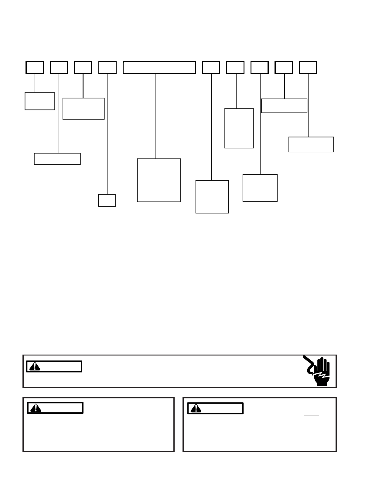
PRODUCT IDENTIFICATION
The model and manufacturing number are used for positive identification of component parts used in manufacturing.
Please use these numbers when requesting service or parts information.
GMS 8 040 3AXAA
PRODUCT
TYPE:
G: Goodman
SUPPLY TYPE
M: Upflow/ H orizontal
FURNACE
TYPE
S: Single-Stage/
Multi-Speed
AFUE
8: 80%
NOMINAL I NPUT
040: 40,000 Bt uh
060: 60,000 Bt uh
080: 80,000 Bt uh
100: 100,000 Bt uh
120: 120,000 Bt uh
140: 140,000 Bt uh
AIRFLOW
CAPABILITY
3: 1200
4: 1600
5: 2000
CABINET
WIDTH
A: 14"
B: 17-1/2"
C: 21"
D: 24-1/2"
MAJOR REVI SION
A: In itia l Rele ase
MI NOR REVIS I ON
A: Initial Release
ADDITIONAL
FEATURES
N: Nat ural Gas
X: Low NOx
WARNING
WARNING
WARNING
WARNING
arising from improper service or service procedures. If
you install or perform service on this unit, you assume
responsibility for any personal injury or property damage
which may result. Many jurisdictions require a license to
install or service heating and air conditioning equipment.
Disconnect ALL power before servicing or installing this unit. Multiple power
sources may be present. Failure to do so may cause property damage, personal
injury or death.
Goodman will not be responsible
for any injury or property damage
2
HIGH VOLTAGE!
WARNING
WARNING
individuals meeting the requirements of an "entry level
technician" as specified by the Air-Conditioning, Heating,
and Refrigeration Institute (AHRI). Attempting to install or
repair this unit without such background may result in
product damage, personal injury or death.
Installation and repair of this unit
should be performed
ONLY by
Page 3
PRODUCT IDENTIFICATION
The model and manufacturing number are used for positive identification of component parts used in manufacturing.
Please use these numbers when requesting service or parts information.
GMS80403A*BB
GMS81405DNCC
GMS80603A*BB
GMS80604B*BB
GMS80804B*BB
GMS80805C*BB
GMS81005C*BB
GMS81205D*BA
*These models available in Natural Gas and Low NOx.
WARNING
WARNING
WARNING
WARNING
property damage, personal injury, reduced unit performance and/or hazardous conditions may result from the
use of such non-approved devices.
The United States Environmental Protection Agency (“EPA”) has issued various regulations regarding the introduction and disposal of refrigerants introduced into this unit. Failure to follow
these regulations may harm the environment and can lead to the imposition of substantial fines.
These regulations may vary by jurisdiction. Should questions arise, contact your local EPA office.
Do not connect or use any device
that is not design certified by Goodman for use with this unit. Serious
WARNING
WARNING
do not store combustible materials or use gasoline or
other flammable liquids or vapors in the vicinity of this
appliance.
To prevent the risk of property
damage, personal injury, or death,
3
Page 4
PRODUCT DESIGN
General Operation
The GMS8 furnaces are equipped with an electronic ignition
device used to light the burners and an induced draft blower
to exhaust combustion products.
An interlock switch prevents furnace operation if the inner
blower door is not in place. Keep the blower access door in
place except for inspection and maintenance. (See illustra-
tion on pages 5 and 6.)
This furnace is also equipped with a self-diagnosing electronic control module. In the event a furnace component is
not operating properly, the control module LED will flash on
and off in a factory-programmed sequence, depending on
the problem encountered. This light can be viewed through
the observation window in the blower access door. Refer to
the Troubleshooting Chart for further explanation of the LED
codes and Abnormal Operation - Integrated Ignition Control
section in the Service Instructions for an explanation of the
possible problem.
The rated heating capacity of the furnace should be greater
than or equal to the total heat loss of the area to be heated.
The total heat loss should be calculated by an approved
method or in accordance with “ASHRAE Guide” or “Manual
J-Load Calculations” published by the Air Conditioning Contractors of America.
*Obtain from: American National Standards Institute 1430
Broadway New York, NY 10018
Location Considerations
• The furnace should be as centralized as is practical
with respect to the air distribution system.
• Do not install the furnace directly on carpeting, tile, or
combustible material other than wood flooring.
• When installed in a residential garage, the furnace
must be positioned so the burners and ignition source
are located not less than 18 inches (457 mm) above
the floor and protected from physical damage by vehicles.
Notes:
WARNING
O PREVENT POSSIBLE PERSONAL INJURY OR D EATH DUE TO ASPHYXIATION,
T
THIS FURNACE MUST BE
ATEGORY
C
VENT IN G.
III
ATEGORY I VENT ED. DO NOT VENT USING
C
NFPA 54/ANSI Z223.1 - latest edition. In Canada, the furnaces must be vented in accordance with the National Standard of Canada, CAN/CSA B149.1 and CAN/CSA B149.2 latest editions and amendments.
NOTE: The vertical height of the Category I venting system
must be at least as great as the horizontal length of the
venting system.
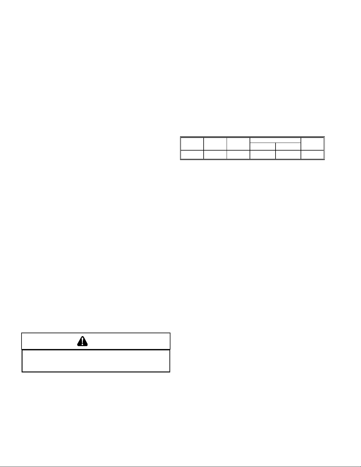
Accessibility Clearances (Minimum)
Unobstructed front clearanace of 24" for servicing is recommended.
MINIMUM CLEARANCE TO COMBUSTIBLE MATERIALS - INCHES
Sides TopRear Front*
103 6 1 1
* 24" clearnace for serviceability recommended.
** Single Wall Vent (SW) to be used only as a conncetor.
Refer to the venting tables outlined in the Installation Manual for
additional venting requirements.
Vent
SW B
Note: In all cases accessibility clearance shall take precedence over clearances from the enclosure where accessibility clearances are greater. All dimensions are given in inches.
High Altitude Derate
IMPORTANT NOTE: The furnace as shipped requires no
change to run between 0 - 5500 feet. Do not attempt to
increase the firing rate by changing orifices or increasing
the manifold pressure below 5500 feet. This can cause poor
combustion and equipment failure.
High altitude installations above 5500 feet may require both
a pressure switch and an orifice change. These changes
are necessary to compensate for the natural reduction in
the density of both the gas fuel and the combustion air at
higher altitude.
For installations above 5500 feet, please refer to your distributor for required kit(s). Contact the distributor for a tabular listing of appropriate manufacturer’s kits for propane gas
and/or high altitude installations. The indicated kits must be
used to insure safe and proper furnace operation. All conversions must be performed by a qualified installer, or service
agency.
Category I Venting is venting at a non-positive pressure. A
furnace vented as Category I is considered a fan-assisted
appliance and the vent system does not have to be “gas
tight.” NOTE: Single stage gas furnaces with induced draft
blowers draw products of combustion through a heat exchanger allowing, in some instances, common venting with
natural draft appliances (i.e. water heaters). All installations
must be vented in accordance with National Fuel Gas Code
4
Page 5

COMPONENT IDENTIFICATION
Pressure Switch
2
3
Flue Pipe Connec tion
4
Induced Draft Blower
Gas Line
5
Entrance
6
Gas Valve
7
Rollout Limit
8
Junction B ox
Tubular Heat Exchanger
1
?
Transformer
Wiring Harness
9
Grommet
Gas Manifold
Inshot Burner
Integrated Control Modu le
Upflow/Horizontal
Gas Line Entrance
(Alternate)
Circulator Blower
Blower Door
Interlock Swit ch
Note: Primary Limit Not Shown
1 Tubular Heat Exchanger
2 Pressure Switch
3 Flue Pipe Connection
4 Induced Draft Blower
5 Gas Line Entrance
6 Gas Valve
7 Rollout Limit
8 Junction Box
9 Wiring Harness Grommet
10 Gas Manifold
11 Inshot Burner
12 Transformer
13 Integrated Control Module
14 Blower Door Interlock Swtich
15 Circulator Blower
16 Gas Line Entrance (Alternate)
5
Page 6

PRODUCT DIMENSIONS
A
A
A
lt. Gas Inlet
GMS8
lt. Gas Inlet
High Voltage Inlet
Low Voltage
lt. High Voltage
Alt. LowVoltage
MODEL A B
GMS80403 A***
14 12 - 1/2
GMS80603 A***
GMS80604 B***
17 - 1/2 16
GMS80804 B***
GMS80805 C***
21 19 - 1/2
GMS81005 C***
GMS81205 D***
GMS81405DN* *
24 - 1/2 23
6
Page 7

PRODUCT DIMENSIONS
GMS8[040-100]BB
GMS81205D*BA
GMS81405DNCC
Pre ssure S witch Trip Points
Trip Point
Model
ID Blower
Pressure
Sw itch
GMS80403A*BB
GMS80603A*BB
GMS80604B*BB
GMS80804B*BB
GMS80805C*BB
GMS81005C*BB
GMS81205D*BA
GMS81405DNCC
For installations in Canada, the GMS furnaces are certifed only to 4,500 ft.
* Negative pressure readings are in inches of water column (*w.c.)
-0.70 B1370158
-0.75 B1370179
-0.75 B1370179
-0.70 B1370158
-0.75 B1370179
-0.70 B1370158
-0.80 0130F000 42
-0.80 0130F000 42
ID Blower
Pressure
Sw itch
Part #
PRIMARY LIM IT
Part Number 20162901 20162904 20162903
Ope n Setting (°F) 210 150 160
GMS80403A*BB 1 --- --GMS80603A*BB --- 1 --GMS80604B*BB --- 1 --GMS80804B*BB --- 1 --GMS80805C*BB --- --- 1
GMS81005C*BB --- 1 --GMS81205D*BA --- --- 1
GMS81405DNCC --- --- 1
ROLLOUT L IMIT SWITCHES
Part Number 10123529
Op en Setting (°F) 300
GMS80403A*BB 2
GMS80603A*BB 2
GMS80604B*BB 2
GMS80804B*BB 2
GMS80805C*BB 2
GMS81005C*BB 2
GMS81205D*BA 2
GMS81405DNCC 2
AUXILIARY LIM IT SWITCHES
Part Number 0130F00038
Ope n S etting (°F) 120
GMS80403A*BB 1
GMS80603A*BB 1
GMS80604B*BB 1
GMS80804B*BB 1
GMS80805C*BB 1
GMS81005C*BB 1
GMS81205D*BA 1
GMS 81405DNCC 1
7
Page 8

PRODUCT DESIGN
Thermostats:
It is recommended that a single-stage heat, non-power robbing thermostat be used. Refer to the product marketing
literature for a complete list of thermostats offered.
THERMOSTATS
Thermostat Man/Auto Programmable Cool Heat Batt. Pow ered Batt. Bkup
1213406*
1213407
1213411
*1213406 is the recommended model for the G*S* furnaces when used with a heat pump in a fossil fuel application.
It is NOT for us e with the G* S 8 as a s ole he at ing s o urce . 12 13 406 th ermsta ts are 24V pow ere d with batte ry
Filters:
Filters are required with this furnace and must be provided by the installer. The filters used must comply with UL900 or
CAN/ULCS111 standards. Installing this furnace without filters will void the unit warranty
backup.
Man. Or Auto Yes 2 3 No No
Man. Changeover Yes 2 2 Yes Yes
Man. Changeover No 2 2 Yes No
Upflow Filters
BOTTOM RETURNS I DE RETURN
Cabinet
Width
(in.)
Al l 16 x 25 x 1 400 17-1/2 14 x 25 x 1 350
Nominal
Filter Size
(in.)
Approx.
Flow Area
2
)
(in
Cabinet
Width
(in.)
21 16 x 25 x 1 400
24-1/2 20 x 25 x 1 500
Nominal
Filter S i ze
(in.)
Approx.
Flow Area
2
)
(in
Refer to Minimum Filter Area tables to determine filter area requirement. NOTE: Filters can also be installed elsewhere in
the duct system such as a central return.
MINIMUM FILTER SI ZES for DISPO SA BLE FILTERS
FURNACE INPUT FI LTER SIZE
40M
60M
320 in
483 in
80M 640 in
100M
120M
140M
DISPOSA BLE NO MINAL 300 F.M. FACE V EL OCITY
800 in
738 in
738 in
2
2
2
2
2
2
8
Page 9

FURNACE SPECIFICATIONS
MODEL
GMS8[040-100]BB
GMS81205D*BA
GMS81405DNCC
GMS80403A*BB
GMS80603A*BB
GMS80604B*BB
GMS80804B*BB
GMS80805C*BB
GMS81005C*BB
GMS81205D*BA
GMS81405DNCC
Btuh Input (US) High Fire 40,000 60,000 60,000 80,000 80,000 100,000 120,000 140,000
Output (US ) High Fire 32,000 48,000 48,000 64,000 64,000 80,000 96,000 112,000
A.F.U.E. 80% 80% 80% 80% 80% 80% 80% 80%
Rated E xternal Static (" w. c . ) .20 - .50 .20 - .50 .20 - .50 .20 - .50 .20 - .50 .20 - .50 .20 - .50 .20 - .50
Temperature R ise (°F ) 25 - 55 25 -55 20 - 50 35 - 65 35 - 65 35 - 65 40 - 70 40 - 70
High Stage Pres sure S witch
Tr ip Point (" w.c.)
-0.70 -0.75 -0 .75 -0.70 -0.75 -0 .70 -0.80 -0.80
Blow er Wh eel (D " x W") 10 X 6 10 x 6 10 x 8 10X8 10x10 10X10 11x10 11x10
Blower Horsepower 1/3 1/3 1/2 1/2 1/2 1/2 3/4 3/4
Blower Speeds 44444444
Max CFM @ 0.5 E.S.P. 1298 1157 1883 1725 1960 1974 2131 2131
Power Supply 115-60-1 115-60-1 115-60-1 115-60-1 115-60-1 115-60-1 115-60-1 115-60-1
Minimu m Circuit Ampac ity (MCA)
Maximum Overcurrent D evic e
(2)
(1)
8.5 8.5 12.9 12 .9 12.9 12.9 15.2 14 .7
15 15 15 15 15 15 15 15
Trans former (VA) 40 40 40 40 40 40 40 40
Heat Anticipator (Amps) 0.7 0.7 0.7 0.7 0.7 0.7 0.7 0.7
Prim ar y Lim it S etting (°F) 210° 150° 150° 150° 160° 150° 160° 160°
Auxiliary Limit Setting (°F) 120° 120° 120° 120° 120° 120° 120° 120°
Rollout Limit Setting (°F) 300° 300° 300° 300° 300° 300° 300° 300°
Gas Supply Pressure
(Natural/Propane) (" w.c.)
Manifold Pressure
(Natural/Propane) High Stage (" w.c.)
7 / 11 7 / 11 7 / 11 7 / 11 7 / 11 7 / 11 7 / 11 7 / 11
3.5 / 10 3.5 / 10 3.5 / 10 3.5 / 10 3.5 / 10 3.5 / 10 3.5 / 10 3.5 / 10
Or ifice S iz e (Natural/Propan e) #45 / #55 #45 / #55 #45 / #55 #45 / #55 #45 / #55 #45 / #55 #45 / #55 #43 / #55
Number of Burners 23344566
Vent Connec tor D iameter (inches )
(3)
44444444
Shipping Weight (lbs.) 84 88 98 106 114 118 130 130
(1)
Wire size should be determined in accordance with National Electrical Codes. Extensive wire runs will require larger wire sizes.
(2)
Maximum Overcurrent Protection Device: May use Time Delay Fuse or HACR type Circuit Breaker of the same size as noted.
(3)
See Installation Instructions for appropriate vent diameter, length and number of elbows.
1. These furnaces are manufactured for natural gas operation. Optional Kits are available for conversion to propane gas operation.
2. For elevations above 2000 ft. the rating should be reduced by 4% for each 1000 ft. above sea level. The furnace must not be derated, orifice
changes should only be made if necessary for altitude.
3. The total heat loss from the structure as expressed in TOTAL BTU/HR must be calculated by the manufactures method in accordance with the
"A.S.H.R.A.E. GUIDE" or "MANUAL J-LOAD CALCULATIONS" published by the AIR CONDITIONING CONTRACTORS OF AMERICA. The total
heat loss calculated should be equal to or less than the heating capacity. Output based on D.O.E. test procedures, steady state efficiency times
output.
4. Minimum Circuit Ampacity calculated as: (1.25 x Circulator Blower Amps) + I.D. Blower Amps.
Unit specifications are subject to change without notice. ALWAYS refer to the unit's serial plate for the most up-to-date general and electrical information.
9
Page 10

BLOWER PERFORMANCE SPECIFICATIONS
(CFM & Temperature Rise vs. External Static Pressure)
GMS8[040-100]BB
GMS81205D*BA
GMS81405DNCC
Model
Motor
Heating Speed
As Shipped
*MS80403A*BB MED 2.5 1160 26 1160 26 1132 26 1121 26 1082 27 1042 997 925
(MEDIUM) MED-LO 2.0 961 31 955 31 948 31 932 32 913 33 882 821 803
*MS80603A*BB MED 2.5 1098 40 1081 4 1 1051 42 103 9 43 1021 4 4 983 924 868
(MEDIUM) MED-LO 2.0 919 48 913 49 892 50 847 ---- 829 ---- 818 792 728
*MS80604B*BB MED 3.5 166827166327165627164527161628154914921391
(MEDIUM) MED-LO 3.0 141931142631142631143231141931137813281261
*MS80804B*BB MED 3.5 1736 ---- 1708 35 1652 36 1611 37 1540 38 1475 1394 1307
(MEDIUM) MED-LO 3.0 169335166836145941142941138943133912741204
*MS80805C*BB MED 4.0 1852 ---- 1820 ---- 1777 ---- 1719 --- 1641 36 1567 1469 1382
(MEDIUM) MED-LO 3.5 161537159237155638151639147040140513461235
*MS81005C*BB MED 4.0 185840184740179941174442167444157714931399
(MEDIUM) MED-LO 3.5 159646158747157147155248149350139713261217
*MS81205D*BA MED 4.0 157556155857154558151359150059141913541271
(MEDIUM) MED-LO 3.5 140263138064134366131967129669124511831106
GMS81405DNCC MED 4.0 157566155867154567151369150069141913541271
(MEDIUM) MED -L O 3 .5 14 0 2 ---- 1380 ---- 1 34 3 ---- 13 1 9 ---- 1296 ---- 1 24 5 1 1 83 1106
Speed
HIGH 3 .0 1 5 2 1 ---- 1466 ---- 14 1 4 ---- 13 7 3 ---- 1298 ---- 1 24 3 1 1 64 1 0 75
LOW 1.5 7 81 38 785 38 781 38 773 38 761 3 2 745 716 668
HIGH 3.0 14223113523313073411973711573810921075983
LOW 1.5 7 5 8 ---- 7 4 1 ---- 7 41 ---- 7 3 3 ---- 6 9 9 ---- 6 77 64 9 62 6
HIGH 4.0 213421210021204222197523188324178617001601
LOW 2.5 1134 39 1145 39 1166 38 1171 38 1160 38 1144 1111 1071
HIGH 4 .0 2 0 5 1 ---- 1983 ---- 18 9 5 ---- 18 1 2 ---- 1725 ---- 1 62 7 1 5 30 1 4 39
LOW 2.5 1200 49 1185 50 1180 50 1173 51 1158 51 1125 1125 1080
HIGH 5 .0 2 2 9 0 ---- 2229 ---- 21 5 5 ---- 20 4 7 ---- 1960 ---- 1 83 7 1 7 12 1 5 84
LOW 3.0 1290 46 1285 4 6 12 65 47 1235 48 1214 49 1174 1044 904
HIGH 5.0 2323 ---- 222 5 ---- 21 20 35 2040 36 1974 38 1801 1688 1 577
LOW 3.0 1291 57 1272 58 1261 59 1257 59 1205 61 1168 1118 1060
HIGH 5 .0 2 4 6 9 ---- 2389 ---- 23 0 0 ---- 22 2 3 40 2131 42 20 2 7 1 9 02 1 7 86
LOW 3.0 12 00 ---- 1 1 86 ---- 1 16 1 ---- 11 2 7 ---- 1082 ---- 1 04 2 995 92 6
HIGH 5.0 246942238943230045222347213149202719021786
LOW 3.0 12 00 ---- 1 1 86 ---- 1 16 1 ---- 11 2 7 ---- 1082 ---- 1 04 2 995 92 6
Ton s AC
at 0.5" 0.6 0.7 0.8
ESP CFM RISE CFM RISE CFM RISE CFM RISE CFM RISE CFM CFM CFM
0.1 0.2 0.3 0.4 0.5
EXTERNAL STATIC PRESSURE (Inches Water Column)
NOTES:
• CFM in chart is without filter(s). Filters do not ship with this furnace, but must be provided by the installer.
• All furnaces ship as hig-speed cooling. Installer must adjust blower cooling speed as needed.
• For most jobs, about 400 CFM per ton when cooling is desirable
• INSTALLATION IS TO BE ADJUSTED TO OBTAIN TEMPERATURE RISE WITHIN THE RANGE SPECIFIED ON THE RATING PLATE.
• The chart is for information only. For satisfactory operation, external static pressure must not exceed values shown on the rating plate. The shaded area insicated
ranges in excess of maximum static pressure allowed when heating.
• The dashed (---) areas indicate a temperature rise not recommended for this model.
• At higher altitudes, a properly de-rated unit will have approximatley the same temperature rise at a particular CFM, while ESP at the CFM will be lower.
10
Page 11

BLOWER PERFORMANCE SPECIFICATIONS
MPER
ATURE R
130 140 150
FORMULAS
BTU OUTP UT
RISE =
BTU OUTPUT = CFM x 1.08 x RISE
100
2400 CFM
2200
2000
1800
1600
1400
1200
1 100
1000
900
800
OUTPUT BTU/HR x 1000
BTU OUTPUT vs TEMPERATURE RISE CHART
600 CFM
700
30 40 50 60 70 80 90 110 120
100
90
80
70
60
ISE
50
TE
40
30
20
10
11
Page 12

WIRING DIAGRAMS
(
)
GMS8
WARNING:DISCONNECT POWER BEFORE
SERV ICING.WIRING TO UNIT MUST BE
24 VAC
HUMIDIFIER
RD
RD
BL
PU
HIGH VOLTAGE!
DISCONNECT ALL POWER BEFORE SERVICING OR INSTALLING THIS
UNIT. MULTIPLE POWER SOURCES MAY BE PRESENT. FAILURE TO
DO SO MAY CAUSE PROPERTY DAMAGE, PERSONAL INJURY OR DEATH.
0
STEADY ON = NORMAL OPERATION
OFF = CONTROL FAILURE
1
1 FLASH = SYSTEM LOCKOUT (RETRIES/RECYCLES EXCEEDED)
2
2 FLASHES = PRESSURE SWITCH STUCK CLOSED
3
3 FLASHES = PRESSURE SWITCH STUCK OPEN
4
4 FLASHES = OPEN HIGH LIMIT
5
5 FLASHES = FLAME SENSE WITHOUT GAS VALVE
6
6 FLASHES = OPEN ROLLOUT
7
7 FLASHES = LOW FLAME SIGNAL
C
RAPID FLASHES = REVERSED 115 VAC POLARITY/VERIFY GND
COLOR CODES :
YL YELLOW
OR ORANGE
PU PUR PLE
GR GREEN
BK BLACK
PROPERLY POLARIZED AND GROUNDED.
W
YRR
GC
FUSE
3
12
4
6
5
8
9
7
12
10
11
BL
CONTROL MODULE
GR
2
1
PU
BK
BK
115 VAC HOT A ND PARK TERMINALS
LINE-H XFMR-H HEAT-H C OOL-H
24V
BK
115V
XFMR
GR
DOOR SWITCH
SWITCH LOCATE D IN BLOWER
COMPARTMENT ON SOME MODELS
BK
WH
BL
HOT
SURFACE
IGNITER
PU
PU
(SI N GLE CO NT RO L ON SOME MOD ELS )
PK PIN K
BR BROWN
WH WHITE
BL BLUE
GY GRAY
RD RED
BK
HI
BR
BR
24 VAC
YL
JUNCTION
TO 115 VAC/ 1/60H Z
POWER SUPPLY WITH
OVERCURRENT PROTECTION
DEVICE
C
24V THERMOSTAT CONNECTIONS
G
TO
Y
MICRO
W
R
XFMR (3)
XFMR-H
INTEGRATED CONTROL MO DUL E
LINE-H
DOOR
SWITCH
WARNING:
DISCONNECT POWER
BEFORE SERVICING.
WIRING TO UNIT
MUST BE
PROPERLY
POLARIZED
AND GROUNDED.
TO 115VAC/ 1
BOX
YL
RD
INTEGRATED
BK
RD
M1
GAS VALVE
ROLLOUT LI MI TS
DIAGNOSTIC
LED
OR
YL
BR
WH
PRIMARY LIMIT
C2
PU
AUXIL I ARY
YL
YL
BR
YL
YL
15 PIN PLUG
ON SOME MODELS
BLOWER COMPARTMENT
BURNER COMPARTMENT
BK
YL
PRESSURE
SWITCH
BK
W
H
INDUCED DRAFT
LIMITS
BR
WH (N)
CICULATOR BLOWER
NO
BK
BLOWER
OR (MED LOW)
RD (LOW)
CAP
HUMIDIFIER
C
WH
BL (MED)
115 VAC NEUTRAL
RD RD
WH
OROR
WHWH
WH
WH
OR
RD
WH
BR
OR
FLAME
SENSOR
LOW VOLTAGE (24V)
LOW VOLTAGE F IELD
H I VOLTAGE (115V)
HI VOLTAG E F I EL D
JUNCTION
TERMINAL
INTERNAL TO
INTEGRATED CONTROL
PLUG CONNECTION
NOTES:
1. SET HEAT ANTICIPATOR ON ROOM THERMOSTAT AT 0.7 AMPS.
2. MANUFACTURER'S SPECIFIED REPLACEMENT PARTS MUST BE USED WHEN SERVICING.
3. IF A NY OF THE ORIGI NAL WIRE AS SUP PLIED WITH THE F URNACE MUST BE
REPLACED, IT MUST BE REPLACED W ITH WIRING MATERIAL HAVING A TEMPERATURE
RATING OF AT LEAST 105
4. BLOWER SPEEDS MU ST BE ADJUSTE D BY INSTAL LER TO MATCH THE INSTALLATIO N
REQUIREMENTS SO AS TO PROVIDE THE CORRECT HEATING TEMPERATURE RISE AND THE
CORRECT COOLING CFM. (SEE SPEC SHEET FOR AIR FLOW CHART)
5. UNIT MUST BE PERMANENTLY GROUNDED AND CONFORM TO N.E.C. AND LOCAL CODES.
C. USE COPPER CONDUCTORS ONLY.
HUMIDIFIER
XFMR (6)
GND (8)
MVC (9)
MV (12)
AUXILIARY
LIMIT CONTROLS
PS (10)
PSO (4)
HLI (7)
HLO (1)
RO2 (11)
RO1 (5)
MAN U AL RES ET ROL L OU T
LIMIT CONTROL(S)
(SINGLE CONTROL ON SOME MODELS)
FP (2)
OVERCURRENT PROTECTION DEVICE
FLAME SENSOR
HOT S URFA CE
IGNITER
IGN
ID
BLWR
IND
COOL-H
C
O
O
L
CIRCULATOR
BLWR
T
A
E
H
HEAT -H
JUNCTION BOX
LGND
Ø /60 HZ POWER SUPPLY WITH
LINE-N
GND
LINE H
INTEGRATED
CONTROL MODULE
GND
C2
M1
C
24 VAC
40 VA
TRANSFORMER
115 VAC
IGN-N
IND-N
CIR- N
N
EQUIPMENT GND
FIELD GND
FIELD SPLICE
SWITCH (TEMP.)
IGNITER
SWITCH ( PRESS.)
OVER C URRENT
PROT. DEVICE
GAS
VALVE
ID BLOWER
PRESSURE
SWITCH
NO
AUTO RESET
PRIMARY
LIMIT
CONTROL
XFMR-N
LINE-N
DISCONNECT
INTEGRATED CONTROL MODULE
12
0140F00119-C
Wiring is subject to change, always refer to the wiring diagram on the unit for the most up-to-date wiring.
Page 13

SCHEMATICS
CIRCULATOR
BLOWER
GMS8
HIGH VOLTAGE!
DISCONNECT ALL POWER BEFORE SERVICING OR INSTALLING THIS
UNIT. MULTIPLE POWER SOURCES MAY BE PRESENT. FAILURE TO
DO SO MAY CAUSE PROPERTY DAMAGE, PERSONAL INJURY OR DEATH.
INDUCER
HEAT COOL PARK PARK
K2
K1
.0005
3M
IGN
FP
FLAME
SENSOR
PROBE
IGNITOR
K5
GND
CIR
NEU
FACTORY
JUMPER
MV MV
GAS
VALVE
K8
PS
IND
K3
FACTORY
JUMPER
HLO
HIGH
LIMIT
PRESSURE
SWITCH
HLI
AUX
LIMIT
PSO
R
RO2
RO1
TH
XFMR
HOT
XFMR
NEU
TR
C
Y
G
W
UT
ROLLO
SWITCH
24 VAC
COMPRESSOR
CONTACTOR
COIL
Y
G
W
THERMOSTAT
R
TYPICAL SCHEMATIC
GMS8 * MODEL FURNACES
WR 50T55-289 INTEGRATED IGNITION CONTROL
This schematic is for reference only. Not all wiring is as shown above. Always refer to the appropriate wiring diagram for the unit being serviced.
13
 Loading...