

Page 1
TECHNICAL MANUTECHNICAL MANU
TECHNICAL MANU
TECHNICAL MANUTECHNICAL MANU
GPC 14 SEER R-410A
Package Air Conditioners
with R-410A
• Refer to Service Manual RS6300011 (Horizontal)
for installation, operation, and troubleshooting information.
• All safety information must be followed as provided in the Service Manual.
• Refer to the appropriate Parts Catalog for part number information.
• Models listed on page 3.
• Models qualify for the 2009 and 2010 Federal Tax Credits for Energy Efficiency**
ALAL
AL
ALAL
**Note that these tax credits are subject to specific requirements set forth in the American Recovery and
Reinvestment Act of 2009 and in the Internal Revenue Code. Goodman recommends that consumers consult
a tax professional if they have questions about the applicability of these credits.
This manual is to be used by qualified, professionally trained HVAC technicians only. Goodman does not
assume any responsibility for property damage or personal injury due to improper service procedures or
services performed by an unqualified person.
Copyright © 2009 - 2010 Goodman Manufacturing Company, L.P.
RT6322007r6
September 2010
Page 2
PRODUCT IDENTIFICATION
Y
A
A
The model and manufacturing number are used for positive identification of component parts used in manufacturing. Please
use these numbers when requesting service or parts information.
GPC1424H
BRAND:
G: Go odm an
Brand
®
PRODUCT
TYPE:
Packag e Un it
PRODUCT
FAMILY:
C: Cooling
PRODUCT
SERIES:
SEER Ratin g
CONFIGURATION:
H: Ho ri zontal
OMINAL
APACIT
4: 24, 000 BTUH
0: 30, 000 BTUH
6: 36, 000 BTUH
2: 42, 000 BTUH
8: 48, 000 BTUH
0: 60, 000 BTUH
41AA
VOLTAGE:
1: 208-230v
1ph/60Hz
REFRIGERANT:
4: R-410A
MAJOR REVISION:
: Initial R elea se
MIN OR REV ISION:
: Init ial Relea s e
WARNING
WARNING
WARNING
arising from improper service or service procedures. If
you install or perform service on this unit, you assume
responsibility for any personal injury or property damage
which may result. Many jurisdictions require a license to
install or service heating and air conditioning equipment.
2
Disconnect ALL power before servicing or installing this unit. Multiple power
sources may be present. Failure to do so may cause property damage, personal
injury or death.
Goodman will not be responsible
for any injury or property damage
WARNING
WARNING
dividuals meeting (at a minimum) the requirements of an
"entry level technician" as specified by the Air-Conditioning, Heating, and Refrigeration Institute (AHRI). Attempting to install or repair this unit without such background
may result in product damage, personal injury or death.
Installation and repair of this unit
should be performed
ONLY by in-
WARNING
HIGH VOLTAGE!
Page 3
PRODUCT IDENTIFICATION
The model and manufacturing number are used for positive identification of component parts used in manufacturing. Please
use these numbers when requesting service or parts information.
5mm
GPC1424H41AA
GPC1430H41AA
GPC1436H41AA
GPC1442H41AA
GPC1448H41AA
GPC1460H41AA
GPC1424H41AB
GPC1430H41AB
GPC1436H41AB
GPC1442H41AB
GPC1448H41AB
AB model specific
5 mm information
begins on page 28.
WARNING
WARNING
Models qualify for the 2009 and 2010 Federal Tax Credits
for Energy Efficiency**
**Note that these tax credits are subject to specific requirements set forth in the American
Recovery and Reinvestment Act of 2009 and in the Internal Revenue Code. Goodman
recommends that consumers consult a tax professional if they have questions about the
applicability of these credits.
The United States Environmental Protection Agency (“EPA”) has issued various regulations regarding the introduction and disposal of refrigerants introduced into this unit. Failure to follow
these regulations may harm the environment and can lead to the imposition of substantial fines.
These regulations may vary by jurisdiction. Should questions arise, contact your local EPA office.
WARNING
WARNING
Serious property damage, personal injury, reduced unit
performance and/or hazardous conditions may result
from the use of such non-approved devices.
Do not connect or use any device
that is not design certified by
Goodman for use with this unit.
WARNING
WARNING
do not store combustible materials or use gasoline or
other flammable liquids or vapors in the vicinity of this
appliance.
To prevent the risk of property
damage, personal injury, or death,
3
Page 4
PRODUCT DESIGN
GPC Package Cooling Units are designed for outdoor installations only in either residential or light commercial applications.
The connecting ductwork (Supply and Return) can be connected for either horizontal or vertical airflow. In the vertical
application a matching Roof Curb is recommended.
A return air filter must be installed behind the return air grille(s)
or provision must be made for a filter in an accessible location within the return air duct. The minimum filter area should
not be less than those sizes listed in the Specification Section. Under no circumstances should the unit be operated
without return air filters.
A 3/4” PVC pipe is provided for removal of condensate water
from the indoor coil In order to provide proper condensate
flow, a drain trap is supplied and shipped loose inside the
unit for field installation. (Do not reduce the drain line size.)
Refrigerant flow control is achieved by use of restrictor orifices. GPC units use the FasTest Access Fitting System
with a saddle that is either soldered to the suction and liquid
lines or is fastened with a locking nut to the access fitting
box (core) and then screwed into the saddle.
move the core from the saddle until the refrigerant
charge has been removed. Failure to do so could result in property damage or personal injury.
The single phase units use permanent split capacitor (PSC)
design compressors. Starting components are therefore not
required for these units. A low microfarad run capacitor assists the compressor to start and remains in the circuit during operation.
All GPC14 units have X-13 indoor blower motors that are energized by a 24V signal from the thermostat and are constant torque motors with very low power consumption. The X13 features an integral control module.
Air for condensing (cooling cycle) is drawn through the outdoor coil by a propeller fan, and is discharged vertically out
the top of the unit. The outdoor coil is designed for .0 static.
No additional restriction (ductwork) shall be applied.
Conditioned air is drawn through the filter(s), field installed,
across the coil and back into the conditioned space by the
indoor blower.
GPC1424-30H41* use Copeland Reciprocating Compressors.
GPC1436-60H41* use Copeland Scroll Compressors. There
are a number of design characteristics which are different
from the traditional reciprocating compressor.
Do not re-
- Due to their design Scroll Compressors are inherently
more tolerant of liquid refrigerant. NOTE: Even though the
compressor section of a Scroll compressor is more tolerant of liquid refrigerant, continued floodback or flooded
start conditions may wash oil from the bearing surfaces
causing premature bearing failure.
- Scroll Compressors use white oil which is compatible
with 3GS oil which may be used if additional oil is required.
- Operating pressures and amp draws may differ from standard reciprocating compressors. This information may be
found in the "Cooling Performance Data" section.
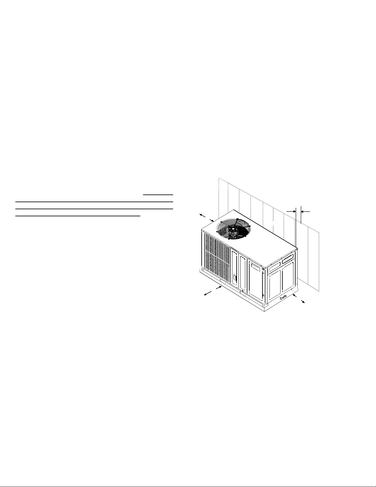
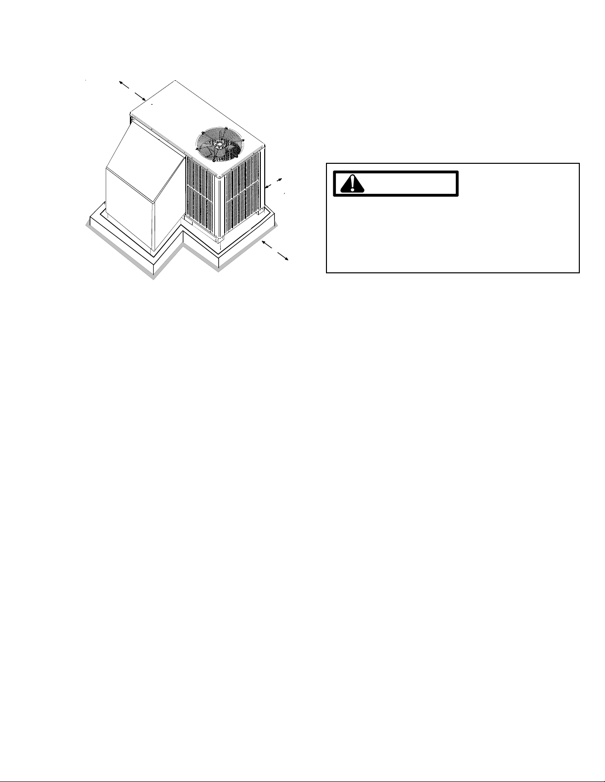
Location and Clearances
NOTE: To ensure proper condensate drainage, unit must be
installed in a level position.
10"
36"
WALL
UNIT
36"
36"
Outside Slab Installation - Horizontal (H)
Minimum clearances are required to avoid air recirculation and
keep the unit operating at peak efficiency.
4
Page 5
PRODUCT DESIGN
36"
U
N
I
T
P
L
E
N
U
M
P
L
A
T
F
O
R
M
Rooftop Installation - Horizontal (H)
In installations where the unit is installed above ground level
and not serviceable from the ground (Example: Roof Top installations), the installer must provide service platform for service person with rails or guards in accordance with local codes
or ordinances or in their absence with the latest edition of the
Uniform Mechanical Code Section 305.
NOTE: Unit can also use roof curb.
24"
WARNING
TO PREVENT POSSIBLE PROPERTY DAMAGE, THE
UNIT SHOULD REMAIN IN AN UPRIGHT POSITION
B
R
U
C
DURING ALL RIGGING AND MOVING OPERATIONS.
TO FACILITATE LIFTING AND MOVING IF A CRANE
36"
IS USED, PLACE THE UNIT IN AN ADEQUATE CABLE
SLING.
Refer to Roof Curb Installation Instructions for proper curb
installation. Curbing must be installed in compliance with
the National Roofing Contractors Association Manual.
5
Page 6
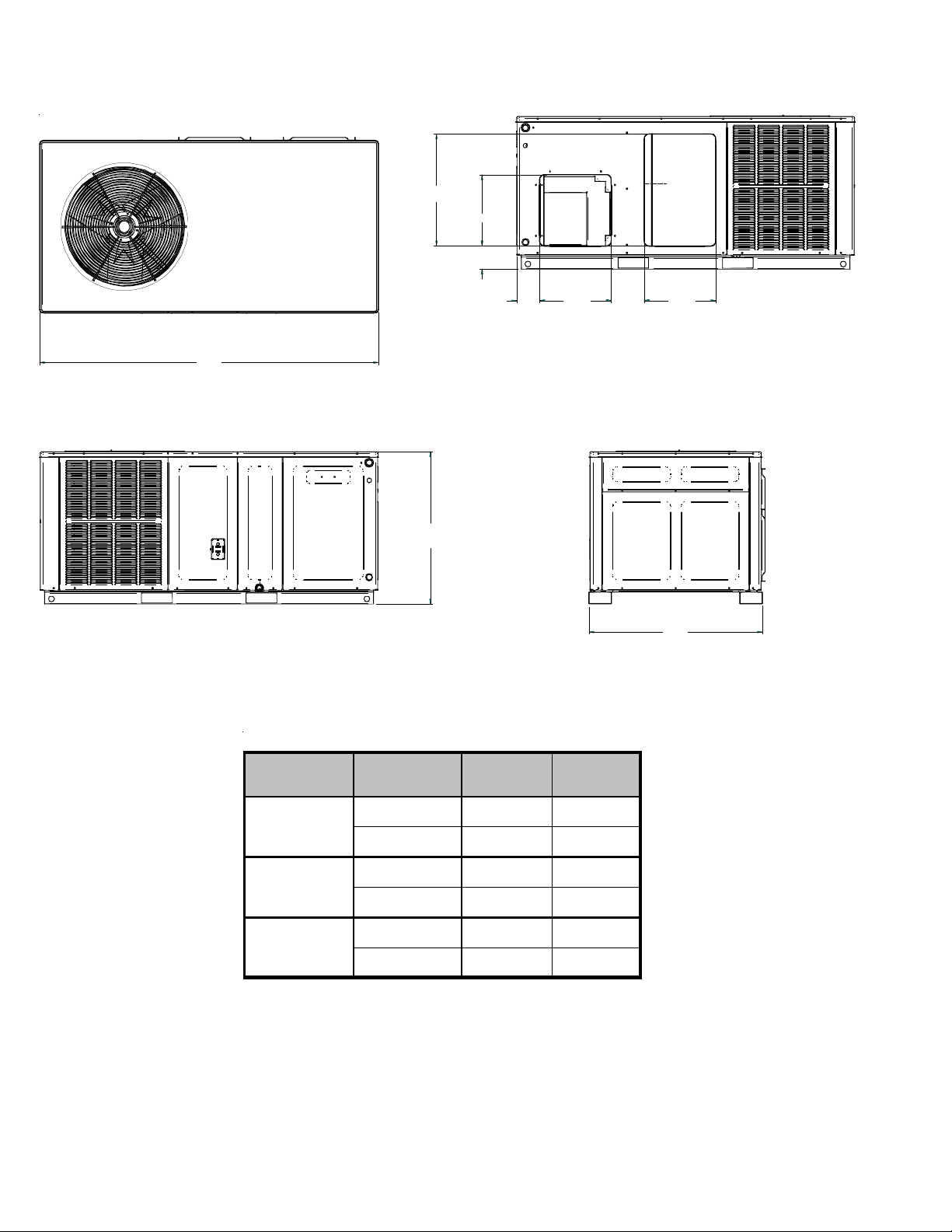
PRODUCT DIMENSIONS GPC14[24-60]H41A*
A
14.000
4.512
66.542
14.000
4.500
SUPPLY
B
6.500
14.000
RETURN
BACK VIEW
(DUCT OPENINGS)
34.075
Chassis Model A B
GPC1424 33 30½
Small
GPC1430 33 30½
GPC1436 33 35½
Medium
GPC1442 33 35½
GPC1448 33 38½
Large
GPC1460 33 38½
Dimensions in inches
6
Page 7
PRODUCT DESIGN
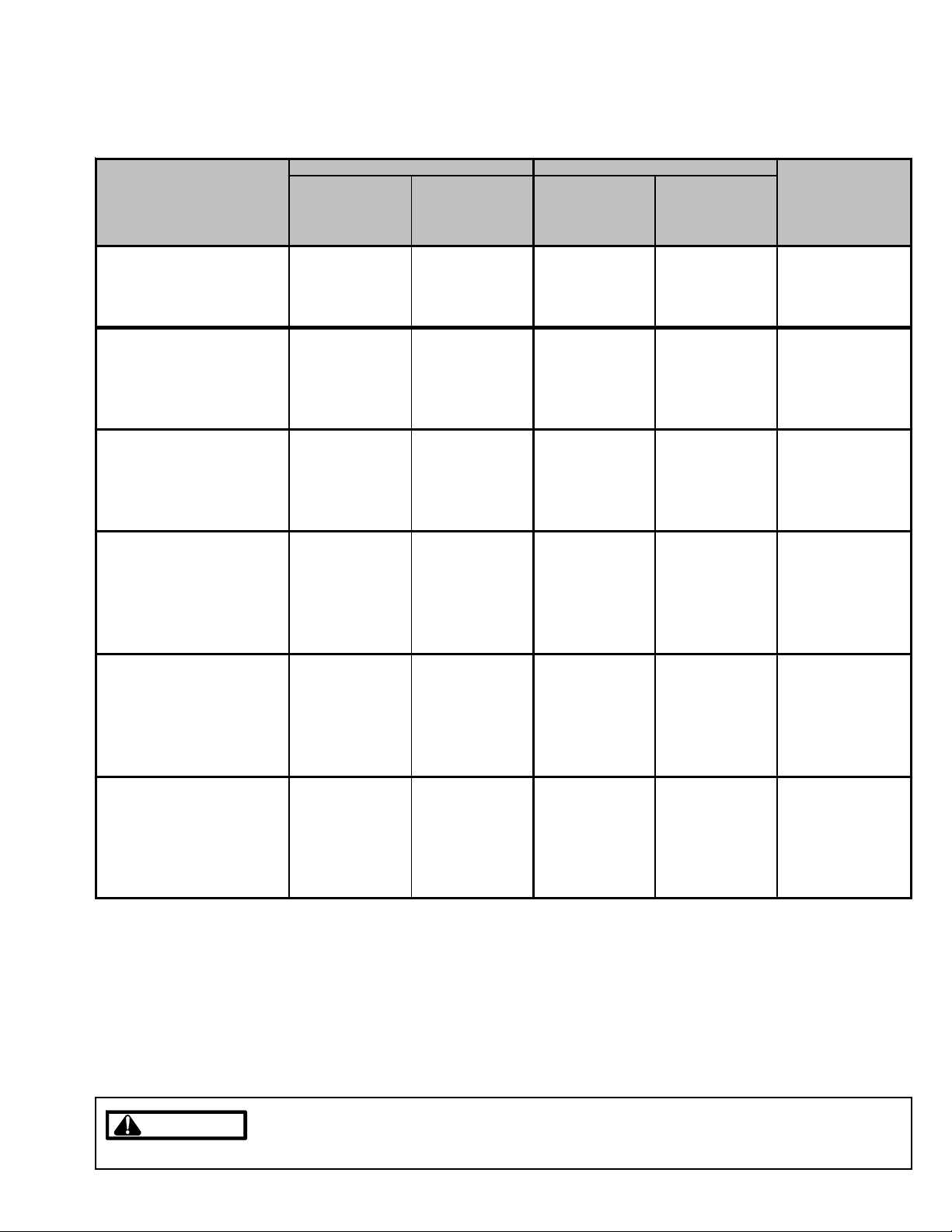
GPC14[24-60]H41A*
HKR ELECTRICAL DATA
Circuit #1 Circuit #2
Model and Heat Kit Usage
GPH1424H41A*
HKR05*,C*
HKR08*,C*
HKR10*,C* 45 / 51 60 / 60 ---- ---- 9.50 / 32,400
GPH1430H41A*
HKR05*,C*
HKR08*,C*
HKR10*,C*
HKR15*,C* 45 / 52 60 / 60 22 / 25 30 / 30 14.25 / 48,600
GPH1436H41A*
HKR05*,C*
HKR08*,C*
HKR10*,C*
HKR15*,C* 45 / 52 60 / 60 22 / 25 30 / 30 14.25 / 48,600
GPH1442H41A*
HKR05*,C*
HKR08*,C*
HKR10*,C*
HKR15*,C*
HKR20*,C* 46 / 52 60 / 60 43 / 49 60 / 60 19.50 / 66,500
GPH1448H41A*
HKR05*,C*
HKR08*,C*
HKR10*,C*
HKR15*,C*
HKR20*,C*
GPH1460H41A*
HKR05*,C*
HKR08*,C*
HKR10*,C*
HKR15*,C*
HKR20*,C* 48 / 54 60 / 60 43 / 49 60 / 60 19.50 / 66,500
Minimum Circuit
Ampacity
at 208 / 240V
24 / 27 30 / 30 ---- ---- 4.75 / 16,200
33 / 28 40 / 40 ---- ---- 7.00 / 23,800
24 / 27 30 / 30 ---- ---- 4.75 / 16,200
34 / 39 40 / 40 ---- ---- 7.00 / 23,800
45 / 52 60 / 60 ---- ---- 9.50 / 32,400
24 / 27 30 / 30 ---- ---- 4.75 / 16,200
34 / 39 40 / 40 ---- ---- 7.00 / 23,800
45 / 52 60 / 60 ---- ---- 9.50 / 32,400
25 / 27 30 / 30 ---- ---- 4.75 / 16,200
34 / 39 40 / 40 ---- ---- 7.00 / 23,800
46 / 52 60 / 60 ---- ---- 9.50 / 32,400
46 / 5 2 60 / 60 22 / 2 5 30 / 3 0 14 .25 / 48,600
25 / 28 30 / 30 ---- ---- 4.75 / 16,200
34 / 40 40 / 40 ---- ---- 7.00 / 23,800
46 / 53 60 / 60 ---- ---- 9.50 / 32,400
46 / 5 2 60 / 60 22 / 2 5 30 / 3 0 14 .25 / 48,600
46 / 5 2 60 / 60 43 / 4 9 60 / 6 0 19 .50 / 66,500
26 / 30 30 / 30 ---- ---- 4.75 / 16,200
36 / 40 40 / 40 ---- ---- 7.00 / 23,800
48 / 54 60 / 60 ---- ---- 9.50 / 32,400
48 / 5 4 60 / 60 22 / 2 5 30 / 3 0 14 .25 / 48,600
Maximum Maximum
Overcurrent Overcurrent
Protection (amps) Protection (a mps)
at 20 8 / 240V at 208 / 240V
Minimum Circuit
Ampacity
at 208 / 240V
kW & BTU
at 240V
Actual
IMPORTANT NOTE: A separate power supply is required for the HKR heater kit.
All wires and overcurrent protection devices are sized for use with electric heaters only and without
WARNING
WARNING
refrigeration. If heaters are not installed with above wire size, overheating and fire could occur. See
PACKAGE COOLING SPECIFICATIONS section for minimum circuit ampacity and maximum overcurrent
protection during refrigeration cycle.
7
Page 8

ACCESSORIES
GPC14[24-60]H41A*
Part Number Description
OT18- 6 0A Outdoor Thermostat Kit w/Lockout Stat
OT/EHR18-60 Emergency He at Relay Kit
HKR Electric Heat Kit
PCCP101-103 Roof Curb
PCP101-103 Downflow Plenum Kit
PCP101-103R8 Downflow Plenum Kit w/ R-8 Insulation
GP CED101-103 Downflow Economizer for GPC- (H) A/C - To Be Used With PCP101-103
GPHED101-103 Downflow Economizer for GPH-(H) Heat Pump - To Be Used With PCP1 01-103
GP CEH101-103 Horizontal Economiz er for GPC-(H) A/C
GP HEH101-103 Horizontal Economizer for GPH-(H) Heat Pump
PCMD101-103 Manual Damper - To Be Used With PCP101-103
PCMDM101-103 Motorized Damper - To Be Used With PCP101-103
GPHMD101-103 Manual Damper for Horizontal Applications
SQRPCH101 Square to Round A dapters 16"&14"
SQ RPCH102-103 Square to Round Adapters 18"&14"
SQRPC101 Square to Round Adapter - For Use With PCCP101-103 Curb 16" Rounds
SQ RPC102-103 Square to Round Adapter For Use With PCCP101-103 Curb 18" Rounds
PCFR101-103 External Horizontal Filter Rack
PCEF101-103 Elbow & Flashing w/ R-8 Liner
CD K36 Flush Mount Concentric Duct Kit
CD K36515 Flush Mount Concentric Duct Kit w/ Filter
CD K36530 Step Down Concentr ic Duct Kit
CD K36535 Step Down Concentr ic Duct Kit w/ Filter
CD K4872 Flush Mount Concentric Duct Kit
CD K4872515 Flush Mount Concentric Duct Kit w/ Filter
CD K4872530 Step Down Concentr ic Duct Kit
CD K4872535 Step Down Concentr ic Duct Kit w/ Filter
8
Page 9
BLOWER PERFORMANCE DATA
Dry Coil Data
GPC14[24-60]H41A*
Model Speed Volts
T1
T2,T3
GPC1424H41**
GPC1430H41**
T4, T5
T1
T2,T3
T4, T5
T1
T2,T3
CFM 934 759 755 638 581 489 - -
230
WATTS957776738390 - -
CFM 990 837 801 744 696 652 601 -
230
WATTS 107 94 105 110 119 133 142 -
CFM 1061 989 947 925 876 - - -
230
WATTS 126 1 34 146 158 169 - - -
CFM 1022 929 894 829 797 748 695 643
230
WATTS 116 114 126 134 144 156 168 173
CFM 1103 1063 1012 962 937 - - -
230
WATTS 142 1 54 165 173 185 - - -
CFM 1285 1240 1202 1163 1124 1076 1046 1003
230
WATTS 205 218 231 244 257 268 280 288
CFM 1234 1111 1071 1024 933 922 - -
230
WATTS 144 1 40 152 164 179 183 - -
CFM 1287 1232 1186 1133 1099 1053 - -
230
WATTS 162 1 75 187 201 213 221 - -
E.S.P (In. of H
0.1 0.2 0.3 0.4 0.5 0.6 0.7 0.8
2
O)
GPC 1436H41**
GPC1442H41**
GPC1448H41**
GPC 1460H41**
T4, T5
T1
T2,T3
T4, T5
T1
T2,T3
T4, T5
T1 , T2, T3
T4, T5
CFM 1381 1325 1277 1233 1181 1144 - -
230
WATTS 195 2 03 217 233 247 258 - -
CFM 1272 1197 1145 1106 1055 998 947 906
230
WATTS 160 168 183 191 211 220 230 243
CFM 1357 1297 1244 1194 1147 1099 1049 1008
230
WATTS 188 202 213 228 245 255 267 284
CFM 1537 1478 1431 1386 1336 1293 1253 1208
230
WATTS 244 258 274 288 303 317 329 341
CFM 1418 1383 1349 1312 1275 1228 1178 1141
230
WATTS 242 258 273 282 299 308 320 338
CFM 1175 1635 1645 1515 1510 1450 1430 1400
230
WATTS 395 420 435 445 455 465 470 475
CFM 1845 1790 1715 1685 1590 1580 1530 1500
230
WATTS 490 505 520 535 550 560 570 575
CFM 1775 1635 1645 1515 1510 1450 1430 1400
230
WATTS 395 420 435 445 455 465 470 475
CFM 2025 1900 1840 1780 1725 1650 1620 1580
230
WATTS 575 595 620 630 645 655 660 670
NOTES :
1. Data shown is dr y coil. Wet coil pres sure drop is approx.
2. 0.1" H
3. Data shown does not include fi l ter pr ess ure drop, approx. 0.08” H
4. Redu ce ai rflow by 2% fo r 208V operation.
O, for 2 row indoor c oil; 0.2” H2O, for 3 row in door coil; and 0.3” H2O, for 4 row indoor coil.
2
O.
2
9
Page 10
BLOWER PERFORMANCE DATA
÷ CFM
130 140 150
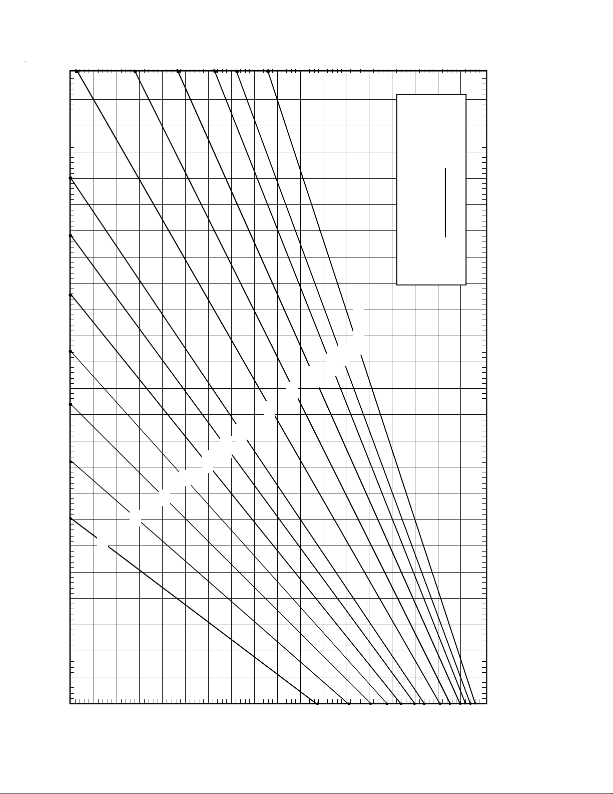
FORMULAS
BTU OUTPUT = CFM x 1.08 x RISE
1.08
BTU OUTPUT
RISE =
100
2400 CFM
2200
2000
1800
1600
1400
1200
1100
1000
900
800
OUTPUT BTU/HR x 1000
10
BTU OUTPUT vs TEMPERATURE RISE CHART
700
600 CFM
30 40 50 60 70 80 90 110 120
100
90
80
70
60
50
40
30
20
10
TEMPERATURE RISE
Page 11
PACKAGE COOLING SPECIFICATIONS
N
)
GPC14[24-30]H41AA
GPC1424H41* GPC1430H41*
COOLING
CAPACITY
UNIT
ELECTRICAL
SPECIFICATION
COMPRESSOR
CONDENSER
FAN MO T OR
COND ENSER F AN
CONDENSER
COIL
EVAPORATOR
BLOWER
MOTOR
EVAPORATOR
BLOWER
EVAPORATOR
COIL
GENERAL
INFORMATION
COOLING CAPACITY, BTUH 24,600 28,400
SEER / EER 14.5 / 12.1 14.0 / 12.1
VOLTAGE (NAMEPLATE) 208-230/1/60 208-230/1/60
AMPS (TOTAL) 10.5 13.16
MI NIMUM CIRCUIT A MPAC ITY 1 2.5 1 5 .6
MAXIMUM OVERCURRENT PROTECTION
(1)
20 25
TYPE RECIP RECIP
RATED LOAD AMPS 7.9 9.8
LOCKED RO TOR AMPS 41 55
HORSEPOWER 1/6 1/4
RPM 815 830
FULL LOAD AMPS 1.1 1.5
LOCKED ROTOR AMPS 1.7 3.0
BLADE DIAMETER (INCHES) / # OF BLADES 22 / 3 22 / 3
FACE AREA - SQ. FT. 13.4 13.4
NUMBER OF ROWS 1 1
FINS PER INCH 24 24
HORSEPO W ER - NO. OF SPEEDS 1/2 - 5 1/2 - 5
FULL LOAD AMPS 1.5 1.86
LOCKED RO TOR AMPS NA NA
MOTOR SPEED TAP - COOLING T2 T2
RPM 1050 1050
DIAMETER X WIDTH (INCHES) 10 X 8 10 X 8
HI E F FICIENCY COOL IN G CFM 850 1,050
5 TON NOM INAL COOLI NG CF M NA N A
FAN ONLY COOLING CFM 800 950
MAX EXT ERNAL ST ATIC PRESS ("w.c.) 0.5 0.5
FACE AREA - SQ. FT. 5.25 5.25
NUMBER OF ROWS 3 3
FINS PER INCH 16 16
FILTER SIZE - SQ . FT. * 20 x 20 x 1 20 x 25 x 1
DRAIN SIZE (IN CH ES) 3/4 " 3/4"
EXPANSION DEVICE ORIFICE (0.057) ORIFICE (0.060)
REFRIGERANT CHARGE R-410 A (Oz.) 83 78
POWER SUPPLY CONDUIT KNOCKOUT SIZE (I
LOW VOLTAGE CONDUIT KNOCKOUT SIZE (IN.
3/4, 1, 1-1/4 3/4, 1, 1-1 /4
1/2 1/2
SHIPPING W EIGHT LBS. 310 310
OPE RAT ING WE IGH T LBS . 30 0 300
(1)
Maximum Overcurrent Protection Device: MUST use Time Delay Fuse or HACR type Circuit Breaker of the same size as noted.
*
Calculated external filter size based on air velocity of 300 ft/min.
Wire size should be determined in accordance with National Electrical Codes. Extensive wire runs will require larger wire sizes.
Unit specifications are subject to change without notice. ALWAYS refer to the units serial plate for the most up-to-date general and electrical information.
IMPORTANT: While this data is presented as a guide, it is important to electrically connect the unit and properly size wires and fuses/circuit breakers
in accordance with the National Electrical Code and/or all local codes. Data shown is w/o electric heaters.
11
Page 12

PACKAGE COOLING SPECIFICATIONS
N
)
GPC14[36-42]H41AA
GPC1436H41* GPC1442H41*
COOLING
CAPACITY
UNIT
ELECTRICAL
SPECIFICATION
COMPRESSOR
CONDENSER
FAN MOTOR
CONDENSER FAN
CONDENSER
COIL
EVAPORATOR
BLOWER
MOTOR
EVAPORATOR
BLOWER
EVAPORATOR
COIL
GENERAL
INFORMATION
COOLING CAPACITY, BTUH 35,600 40,000
SEER / EER 14.0 / 12 .0 14.2/ 12.0
VOLTAGE (NAMEPLATE) 208-230/1/60 208-230/1/60
AMPS (TOTAL) 20.06 22.2
MINIMUM CIRCU IT AMPACITY 24.2 26.6
MAXIMUM OVERCURREN T PROTECTION
(1)
40 40
TYPE SCROLL SC ROLL
RATED LOAD AMPS 16.7 1 7.9
LOCKED ROTOR AMPS 7 9 112
HORSEPOWER 1/4 1/4
RPM 830 1075
FULL LOAD AMPS 1.5 1.4
LOCKED ROTOR AMPS 3. 0 2.9
BLADE DI AMETER (INCHES) / # OF BLADES 22 / 3 22 / 4
FACE AREA - SQ. FT. 13.4 17.0
NUMBER OF ROWS 1 1
FINS PER INCH 24 24
HORSEPOWER - N O. OF SPEEDS 1/2 - 5 1/2 - 5
FULL LOAD AMPS 1.86 2.9
LOCKED ROTOR AMPS NA NA
MOTOR SPEED TAP - COOLING T2 T2
RPM 1050 1050
DIAMETER X WIDTH (INCHES) 10 X 8 10 x 8
HI EFFICIENCY COOLING CFM 1,200 1,300
5 TON NOMINAL COOLING C F M N A NA
FA N ONLY COOL I NG CF M 1 , 10 0 1,200
MAX EXTERNAL STATIC PRESS ("w.c.) 0.5 0.5
FACE AREA - SQ. FT. 5.2 6.2
NUMBER OF ROWS 3 4
FINS PER INCH 14 14
FI LTER SIZE - SQ. FT . * 25 x 25 x 1 (2) 20 x 20 x 1
D RA IN S IZE (INC HES) 3 /4" 3/4"
EXPANSION DEVICE ORIFICE (0.065) ORIFICE (0.072)
REFRIGERANT CHARGE R-410A (Oz.) 80 118
POWER SUPPLY CONDUIT KNO CKOUT SIZE (I
LOW VOLTAGE CONDUIT KNOCKOUT SIZE (IN.
3/4, 1, 1-1/4 3/4, 1, 1-1/4
1/2 1/2
SHIPPIN G WE IGHT LBS. 370 370
OPERATING WEIGHT L BS. 360 360
(1)
Maximum Overcurrent Protection Device: MUST use Time Delay Fuse or HACR type Circuit Breaker of the same size as noted.
*
Calculated external filter size based on air velocity of 300 ft/min.
Wire size should be determined in accordance with National Electrical Codes. Extensive wire runs will require larger wire sizes.
Unit specifications are subject to change without notice. ALWAYS refer to the units serial plate for the most up-to-date general and electrical information.
IMPORTANT: While this data is presented as a guide, it is important to electrically connect the unit and properly size wires and fuses/circuit breakers
in accordance with the National Electrical Code and/or all local codes. Data shown is w/o electric heaters.
12
Page 13
PACKAGE COOLING SPECIFICATIONS
GPC14[48-60]H41AA
GPC1448H41* GPC1460H41*
COOLING
CAPACITY
UNIT
ELECTRICAL
SPECIFICATION
COMPRESSOR
CONDENSER
FAN MOTOR
CONDEN SE R FAN
CONDENSER
COIL
EVAPORATOR
BLOWER
MOTOR
EVAPORATOR
BLOWER
EVAPORATOR
COIL
GENERAL
INFORM ATION
COOLING CAPACITY, BTUH 46,50 0 57,500
SEER / EER 14.5 / 12.0 14.5 / 12.0
VOLTAGE (NAMEPLATE) 208-230/1/60 208-230/1/60
AMPS (T OTA L ) 24.2 30. 7
MINI MUM CIRCUIT AMPACI T Y 29.1 37.3
MAXIMUM OVERCURRENT PROTECTION
TYPE SCROLL SCROLL
RAT ED LOAD AMPS 19.9 26. 4
LOCKED ROTOR AMPS 109 134
HORSEPOWER 1/4 1/4
RPM 1075 1075
FULL LOAD A MPS 1.4 1. 4
LOCKED ROTOR AMPS 2.9 2.9
BL ADE DIAMETER (INCHES) / # O F BLADES 22 / 4 22 / 4
FACE AREA - SQ. FT. 19.1 19.1
NUM BE R OF ROWS 1 2
FI NS PE R INCH 21 16
HO RS EPOWE R - NO . OF SPEEDS 3/4 - 5 3/4 - 5
FULL LOAD A MPS 2.9 2. 9
LOC KED ROTOR AM PS NA NA
MOTOR SP EED T AP - COOLING T2 T2
RPM 1050 1050
DIAMETER X WIDTH (INCHES) 10 x 8 11 x 8
HI EFFICIENCY COOLING CFM 1,600 1,600
5 TON NOMINAL COOLING CFM NA 1,800
FAN ON LY COOLIN G CFM 1,4 00 1,600
MAX EXTERNAL STATIC PRESS ("w.c.) 0.5 0 .5
FACE AREA - SQ. FT. 6.2 7. 0
NUM BE R OF ROWS 4 4
FI NS PE R INCH 14 14
FILTER SIZE - SQ. FT. * (2) 20 x 20 x 1 (2) 20 x 25 x 1
DRAIN SIZE (INCHES) 3/4" 3/4"
EXPANSION DEVICE ORIFICE (0.076) ORIFICE (0.088)
REFRIGERANT CHARGE R-410A (Oz.) 123 188
POWER SUPPLY CONDUIT KNOCKOUT SIZE (IN.) 3/4, 1, 1-1/4 3/4, 1, 1-1/4
LO W VOLT AG E CONDUI T KNOCKOU T SIZE (IN.) 1/2 1/2
SHIPPING WEIGHT LBS. 400 400
OPERATING WEIGHT L BS. 390 390
(1)
45 60
(1)
Maximum Overcurrent Protection Device: MUST use Time Delay Fuse or HACR type Circuit Breaker of the same size as noted.
*
Calculated external filter size based on air velocity of 300 ft/min.
Wire size should be determined in accordance with National Electrical Codes. Extensive wire runs will require larger wire sizes.
Unit specifications are subject to change without notice. ALWAYS refer to the units serial plate for the most up-to-date general and electrical information.
IMPORTANT: While this data is presented as a guide, it is important to electrically connect the unit and properly size wires and fuses/circuit breakers
in accordance with the National Electrical Code and/or all local codes. Data shown is w/o electric heaters.
13
Page 14
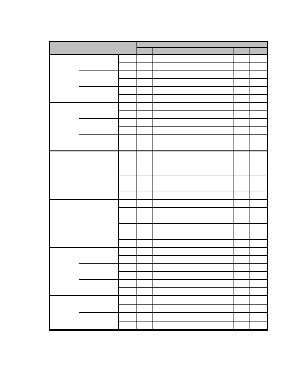
COOLING PERFORMANCE DA TA GPC1424H41AA
COOLING OPERATION
EXPANDED PERFORMANCE DATA
15 11 20 18 15 10 19 17 14 10
8.7 9.1 8.8 9.0 9.3 9.6 9.3 9.5 9.8 10.2
389 406 386 415 438 457 426 458 484 505
151 160 136 145 158 168 141 150 163 174
2.04 2.11 2.01 2.06 2.13 2.20 2.08 2.13 2.20 2.28
25.4 27.3 21.7 22.3 24.1 25.9 20.1 20.7 22.4 24.0
0.63 0.40 0.96 0.86 0.65 0.42 0.97 0.87 0.66 0.42
19
8.5
369
138
1.97
23.5
0.83
Outdoor Ambient Temp erature
Entering Indoor Wet Bulb Temperature
16 11 21 19 16 11 19 18 15 10
8.7 9.0 8.7 8.9 9.2 9.5 9.2 9.4 9.7 10.1
386 402 382 411 434 452 422 454 479 500
149 159 135 143 156 166 139 148 162 172
2.02 2.09 1.99 2.04 2.11 2.18 2.06 2.11 2.19 2.26
24.7 26.5 21.0 21.7 23.4 25.2 19.5 20.1 21.7 23.3
0.60 0.38 0.92 0.82 0.62 0.40 0.92 0.83 0.63 0.40
19
8.4
365
137
1.95
22.8
0.79
16 11 21 20 16 11 20 18 15 10
8.4 8.7 8.5 8.7 9.0 9.3 9.0 9.2 9.5 9.8
374 390 370 398 421 439 409 440 465 485
145 154 131 139 152 161 135 144 157 167
1.97 2.03 1.94 1.98 2.05 2.12 2.01 2.06 2.13 2.20
22.8 24.4 19.4 20.0 21.6 23.2 18.0 18.5 20.0 21.5
0.58 0.37 0.88 0.79 0.60 0.39 0.89 0.80 0.60 0.39
20
8.2
354
133
1.90
21.0
0.76
14
65 75 85 95 105 115
S/T 0.74 0.62 0.43 - 0.77 0.64 0.45 - 0.79 0.66 0.46 - 0.82 0.68 0.47 - 0.85 0.71 0.49 - 0.85 0.71 0.49 -
MBh 24.1 25.0 27.4 - 23.5 24.4 26.7 - 23.0 23.8 26.1 - 22.4 23.2 25.5 - 21.3 22.1 24.2 - 19.7 20.5 22.4 -
Design Subcooling, 9 ± 2°F @ the l iquid access fitting connection AHRI 95 test conditions. Design Superheat 5 ± 2°F @ the compressor suction access fi tt ing co n n ection .
MODE L: GPC 1424H41A*
IDB*Airflow 59636771596367715963677159 63 67 715963677159636771
Delta T 171511 - 171511 - 171511 - 18 15 12 - 171511 - 161411 -
AMPS 6.6 6.8 7.0 - 7.1 7.3 7.5 - 7.7 7.9 8.1 - 8.2 8.4 8.7 - 8.7 8.9 9.2 - 9.2 9.4 9.7 -
HI PR 233 251 265 - 262 282 298 - 298 321 338 - 339 365 386 - 382 411 4 34 - 422 454 479 -
955 KW 1.57 1.60 1.66 - 1.70 1.73 1.79 - 1.81 1.85 1.91 - 1.91 1.95 2.02 - 1.99 2.04 2.11 - 2.06 2.11 2.19 -
S/T 0.71 0.59 0.41 - 0.73 0.61 0.42 - 0.75 0.63 0.44 - 0.78 0.65 0.45 - 0.81 0.67 0.47 - 0.81 0.68 0.47 -
MBh 23.4 24.3 26.6 - 22.9 23.7 26.0 - 22.3 23.1 25.3 - 21.8 22.6 24.7 - 20.7 21.4 23.5 - 19.2 19.9 21.8 -
LO PR 111 118 129 - 118 125 137 - 122 130 142 - 128 137 149 - 135 143 156 - 139 148 162 -
Delta T 181612 - 181612 - 181612 - 18 16 12 - 181612 - 171511 -
70 850 KW 1.56 1.59 1.64 - 1.68 1.72 1.78 - 1.79 1.83 1.90 - 1.89 1.93 2.00 - 1.97 2.02 2.09 - 2.05 2.09 2.17 -
AMPS 6.6 6.7 6.9 - 7.1 7.2 7.5 - 7.7 7.8 8.1 - 8.1 8.3 8.6 - 8.6 8.8 9.1 - 9.1 9.3 9.6 -
HI PR 231 249 263 - 259 279 295 - 295 317 335 - 336 361 382 - 378 407 4 29 - 418 449 474 -
S/T 0.68 0.57 0.40 - 0.71 0.59 0.41 - 0.73 0.61 0.42 - 0.75 0.63 0.43 - 0.78 0.65 0.45 - 0.78 0.66 0.45 -
MBh 21.6 22.4 24.5 - 21.1 21.9 24.0 - 20.6 21.3 23.4 - 20.1 20.8 22.8 - 19.1 19.8 21.7 - 17.7 18.3 20.1 -
LO PR 110 117 128 - 116 124 135 - 121 129 141 - 127 135 148 - 133 142 155 - 138 147 160 -
Delta T 181612 - 181612 - 181612 - 19 16 12 - 181612 - 171511 -
745 KW 1.52 1.55 1.60 - 1.64 1.68 1.73 - 1.75 1.79 1.85 - 1.84 1.88 1.95 - 1.92 1.97 2.03 - 1.99 2.04 2.11 -
AMPS 6.4 6.6 6.8 - 6.9 7.1 7.3 - 7.5 7.6 7.9 - 7.9 8.1 8.4 - 8.4 8.6 8.9 - 8.9 9.1 9.4 -
HI PR 224 241 255 - 252 271 286 - 286 308 325 - 326 351 370 - 367 394 4 17 - 405 436 460 -
LO PR 107 114 124 - 113 120 131 - 117 125 136 - 123 131 143 - 129 137 150 - 134 142 155 -
S/T 0.84 0.76 0.57 0.37 0.88 0.78 0.59 0.38 0.90 0.80 0.61 0.39 0.93
MBh 24.5 25.2 27.3 29.3 23.9 24.7 26.7 28.6 23.4 24.1 26.0 28.0 22.8
Delta T 20181510201915112019151120
955 KW 1.58 1.62 1.67 1.73 1.71 1.75 1.81 1.87 1.82 1.87 1.93 2.00 1.92
AMPS 6.76.87.17.37.27.47.67.97.88.08.28.58.3
HI PR 236 254 268 279 265 285 301 314 301 324 342 357 34 3
S/T 0.81 0.72 0.55 0.35 0.83 0.75 0.57 0.36 0.86 0.77 0.58 0.37 0.88
MBh 23.8 24.5 26.5 28.5 23.2 23.9 25.9 27.8 22.7 23.4 25.3 27.1 22.1
LO PR 112 120 131 139 119 126 138 147 123 131 143 153 130
Delta T 21191611211916112119161121
75 850 KW 1.57 1.60 1.66 1.71 1.70 1.73 1.79 1.85 1.81 1.85 1.91 1.98 1.91
AMPS 6.66.87.07.27.17.37.57.87.77.98.18.48.2
HI PR 233 251 265 277 262 282 298 310 298 321 339 353 33 9
S/T 0.78 0.69 0.53 0.34 0.81 0.72 0.55 0.35 0.83 0.74 0.56 0.36 0.85
MBh 22.0 22.6 24.5 26.3 21.5 22.1 23.9 25.7 20.9 21.6 23.3 25.1 20.4
LO PR 111 118 129 138 118 125 137 145 122 130 142 151 128
Delta T 21191611212016112120161121
745 KW 1.53 1.56 1.61 1.67 1.65 1.69 1.75 1.81 1.76 1.80 1.86 1.93 1.86
AMPS 6.56.66.87.17.07.17.37.67.57.77.98.28.0
HI PR 226 244 257 268 254 273 289 301 289 311 328 343 32 9
LO PR 108 115 125 134 114 121 133 141 119 126 138 147 125
* IDB: Entering Indoor Dry Bulb Tempe rature NOTE: Shaded area is ACCA (TVA) conditions
High and low pr es sures are measured at the liquid and suction access fittings.
Page 15

COOLING PERFORMANCE DA TA GPC1424H41AA
COOLING OPERATION
16 23 22 19 16 21 21 18 14
9.1 8.8 9.0 9.3 9.6 9.3 9.5 9.8 10.2
406 386 415 438 457 426 458 484 505
2.11 2.01 2.06 2.13 2.20 2.08 2.13 2.21 2.28
2.04
160 136 145 158 168 141 150 163 174
8.8
390
151
26.3 21.4 21.9 23.4 25.0 19.8 20.3 21.6 23.1
0.55 1.00 0.94 0.77 0.57 1.00 0.95 0.77 0.58
20
24.6
0.74
EXPANDED PERFORMANCE DATA
Outdoor Ambient Temp erature
Entering Indoor Wet Bulb Temperature
65 75 85 95 105 115
S/T 0.93 0.87 0.71 0.53 0.96 0.90 0.73 0.55 1.00 0.92 0.75 0.56 1.00 0.95 0 .78 0.58 1.00 1.00 0.81 0.60 1.00 1.00 0.81 0.61
MBh 25.0 25.5 27.2 29.1 24.4 24.9 26.6 28.4 23.8 24.3 26.0 27.8 23.2 23.7 25.3 27.1 22.0 22.5 24.1 25.7 20.4 20.9 22.3 23.8
Delta T22211915232219152322191522 22 19 152122191520201714
AMPS 6.86.97.17.47.37.47.77.97.98.08.38.68.4 8.6 8.8 9.18.99.19.49.79.49.69.910.3
HI PR 238 256 271 282 267 288 304 317 304 327 345 360 346 373 393 410 389 419 443 462 430 463 489 510
S/T 0.88 0.83 0.67 0.50 0.92 0.86 0.70 0.52 0.94 0.88 0.72 0.54 0.97 0.91
MBh 24.2 24.8 26.4 28.3 23.7 24.2 25.8 27.6 23.1 23.6 25.2 27.0 22.5 23.0
LO PR 114 121 132 140 120 128 139 148 125 133 145 154 131 139 152 162 137 146 159 170 142 151 165 176
Delta T23221915232220162322201624 23
AMPS 6.76.87.17.37.27.47.67.97.88.08.28.58.3 8.5
HI PR 236 2 54 2 68 2 79 265 285 301 3 14 3 0 1 324 342 357 343 3 69
S/T 0.85 0.80 0.65 0.49 0.88 0.83 0.67 0.50 0.91 0.85 0.69 0.52 0.93 0.88 0 .71 0.53 0.97 0.91 0.74 0.55 0.98 0.92 0.75 0.56
MBh 22.4 22.8 24.4 26.1 21.8 22.3 23.8 25.5 21.3 21.8 23.3 24.9 20.8 21.3 22.7 24.3 19.8 20.2 21.6 23.1 18.3 18.7 20.0 21.4
LO PR 112 120 131 139 119 126 138 147 123 131 143 153 130 138
Delta T24232016242320162423201624 23 20 162423201622211815
AMPS 6.56.76.97.17.07.27.47.77.67.88.08.38.1 8.3 8.5 8.88.68.89.09.49.09.39.69.9
NO TE: Shaded area r eflec ts AH RI ra ting condi tions
S/T 0.97 0.94 0.85 0.69 1.00 0.97 0.88 0.71 1.00 1.00 0.90 0.73 1.00 1.00 0 .93 0.75 1.00 1.00 0.96 0.78 1.00 1.00 0.97 0.79
HI PR 229 246 260 271 257 276 292 304 292 314 332 346 332 358 378 394 374 403 425 443 413 445 470 490
MBh 25.4 25.9 27.1 28.9 24.8 25.3 26.5 28.2 24.2 24.7 25.8 27.6 23.6 24.1 25.2 26.9 22.4 22.9 24.0 25.6 20.8 21.2 22.2 23.7
LO PR 109 116 127 135 115 123 134 143 120 127 139 148 126 134 146 156 132 140 153 163 136 145 158 169
Delta T24232219242422192324221923 23 23 192222221920202118
AMPS 6.87.07.27.47.37.57.78.07.98.18.48.78.4 8.6 8.9 9.28.99.29.59.89.59.710.010.4
HI PR 241 259 273 285 270 290 307 320 307 330 349 364 350 376 397 414 393 423 447 466 435 468 494 515
S/T 0.93 0.89 0.81 0.65 0.96 0.93 0.84 0.68 0.98 0.95 0.86 0.70 1.00 0.98 0 .88 0.72 1.00 1.00 0.92 0.75 1.00 1.00 0.93 0.75
MBh 24.6 25.1 26.3 28.1 24.1 24.5 25.7 27.4 23.5 24.0 25.1 26.8 22.9 23.4 24.5 26.1 21.8 22.2 23.3 24.8 20.2 20.6 21.5 23.0
LO PR 115 122 133 142 121 129 141 150 126 134 146 156 132 141 154 164 139 148 161 172 143 153 167 177
Delta T25242320252523202525232025 25 23 202424232022222219
AMPS 6.86.97.17.47.37.47.77.97.98.08.38.68.4 8.6 8.8 9.18.99.19.49.79.49.69.910.3
HI PR 238 256 271 282 267 288 304 317 304 327 345 360 346 373 393 410 389 419 443 462 430 463 489 510
S/T 0.89 0.86 0.78 0.63 0.93 0.89 0.81 0.65 0.95 0.92 0.83 0.67 0.98 0.95 0 .85 0.69 1.00 0.98 0.89 0.72 1.00 0.99 0.89 0.72
MBh 22.7 23.2 24.3 25.9 22.2 22.6 23.7 25.3 21.7 22.1 23.2 24.7 21.2 21.6 22.6 24.1 20.1 20.5 21.5 22.9 18.6 19.0 19.9 21.2
LO PR 114 121 132 140 120 128 139 148 125 133 145 154 131 139 152 162 137 146 159 170 142 151 165 176
Delta T25252320252524202525242026 25 24 212525232023232219
AMPS 6.66.76.97.27.17.27.57.77.77.88.18.48.1 8.3 8.6 8.98.68.89.19.49.19.39.610.0
HI PR 231 249 263 274 259 279 295 307 295 317 335 349 336 361 382 398 378 407 429 448 417 449 474 495
LO PR 110 117 128 136 116 124 135 144 121 129 141 150 127 135 148 157 133 142 155 165 138 147 160 170
Design Subcooling, 9 ± 2°F @ the liquid access fitting connection AHRI 95 test conditions. Design Superheat 5 ± 2°F @ the compressor suction access fi t t ing co n n ection.
MODE L: GPC 1424H41A*
IDB*Airflow 59636771596367715963677159 63 67 715963677159636771
955 KW 1.60 1.63 1.69 1.74 1.72 1.76 1.82 1.89 1.84 1.88 1.95 2.01 1.94 1.99 2.05 2.13 2.03 2.07 2.15 2.22 2.10 2.15 2.22 2.30
80 850 KW 1.58 1.62 1.67 1.73 1.71 1.75 1.81 1.87 1.82 1.87 1.93 2.00 1.92 1.97
745 KW 1.54 1.58 1.63 1.68 1.67 1.70 1.76 1.82 1.78 1.82 1.88 1.94 1.87 1.92 1.98 2.05 1.96 2.00 2.07 2.14 2.03 2.07 2.15 2.22
955 KW 1.61 1.64 1.70 1.76 1.74 1.78 1.84 1.90 1.86 1.90 1.96 2.03 1.96 2.00 2.07 2.14 2.04 2.09 2.16 2.24 2.12 2.17 2.24 2.32
85 850 KW 1.60 1.63 1.69 1.74 1.72 1.76 1.82 1.89 1.84 1.88 1.95 2.01 1.94 1.99 2.05 2.13 2.03 2.07 2.15 2.22 2.10 2.15 2.22 2.30
745 KW 1.56 1.59 1.64 1.70 1.68 1.72 1.78 1.84 1.79 1.83 1.90 1.96 1.89 1.93 2.00 2.07 1.97 2.02 2.09 2.16 2.05 2.09 2.17 2.24
High and low pres sures are meas ur ed at the liquid and suction access fit tings. AMPS: U nit amps (comp.+ ev aporator + condenser fan motors)
* N OTE: Shaded are a i s AHR I Rating Cond iti ons IDB: Ente r i ng In door Dry B ul b T emperat ure KW = Total system power
15
Page 16

COOLING PERFORMANCE DA TA GPC1430H41AA
COOLING OPERATION
EXPANDED PERFORMANCE DATA
15 10 19 18 14 10 18 16 14 9
400 417 396 426 450 469 437 470 497 518
29.3 31.5 25.0 25.8 27.9 29.9 23.2 2 3.9 25.8 27.7
0.64 0.41 0.98 0.88 0.67 0.43 0.99 0.89 0.67 0.43
18
27.1
0.85
Outdoor Ambient Temp erature
Entering Indoor Wet Bulb Temperature
151 161 136 145 158 168 141 150 163 174
2.41 2.49 2.38 2.43 2.52 2.61 2.47 2.52 2.61 2.70
10.1 10.5 10.2 10.4 10.7 11.1 10.8 1 1.0 11.4 11.8
9.8
378
138
2.33
15 11 20 18 15 10 19 17 14 10
396 413 392 422 445 464 433 466 492 513
28.5 30.6 24.3 25.0 27.1 29.0 22.5 2 3.2 25.1 26.9
0.61 0.39 0.94 0.84 0.64 0.41 0.95 0.85 0.64 0.41
19
26.3
0.81
149 159 135 143 156 167 139 148 162 172
2.39 2.47 2.36 2.41 2.50 2.58 2.44 2.50 2.59 2.68
10.0 10.4 10.1 10.3 10.7 11.0 10.7 1 0.9 11.3 11.7
9.7
375
137
2.31
16 11 20 19 15 11 19 17 14 10
9.8 10.1 9.8 10.1 10.4 10.7 10.4 10.6 11.0 11.4
384 400 380 409 432 450 420 452 477 498
145 154 131 139 152 162 135 144 157 167
26.3 28.2 22.4 23.1 25.0 26.8 20.8 2 1.4 23.1 24.8
24.3
2.33 2.41 2.30 2.35 2.43 2.52 2.38 2.44 2.52 2.61
0.59 0.38 0.90 0.81 0.61 0.39 0.91 0.82 0.62 0.40
19
9.5
363
133
2.25
0.78
16
65 75 85 95 105 115
S/T 0.76 0.63 0.44 - 0.79 0.66 0.46 - 0.81 0.67 0.47 - 0.83 0.70 0.48 - 0.87 0.72 0.50 - 0.87 0.73 0.50 -
MBh 27.8 28.8 31.6 - 27.2 28.2 30.9 - 26.5 27.5 30.1 - 25.9 26.8 29.4 - 24.6 25.5 27.9 - 22.8 23.6 25.9 -
Design Subcooling, 10 ± 2 °F @ the liquid ac cess fitting connection ARI 95 test conditions . Design S uperheat 10 ± 2 °F @ the compressor sucti on acc ess fitting co nnecti o n.
MODE L: GPC 1430H41A*
IDB*Airflow 59636771596367715963677159 63 67 715963677159636771
Delta T161411 - 171411 - 171411 - 17 15 11 - 171411 - 151310 -
AMPS 7.7 7.9 8.1 - 8.3 8.5 8.7 - 8.9 9.1 9.4 - 9.5 9.7 10.0 - 10.1 10.3 10.7 - 10.7 10.9 11.3 -
HI PR 240 258 272 - 269 289 30 5 - 306 329 347 - 348 37 5 396 - 392 421 4 45 - 433 466 492 -
1180 KW 1.86 1.90 1.96 - 2.01 2.06 2.12 - 2.14 2.19 2.27 - 2.26 2.31 2.39 - 2.36 2.41 2.50 - 2.44 2.50 2.59 -
S/T 0.73 0.61 0.42 - 0.75 0.63 0.43 - 0.77 0.64 0.45 - 0.80 0.66 0.46 - 0.83 0.69 0.48 - 0.83 0.70 0.48 -
MBh 27.0 28.0 30.7 - 26.4 27.4 30.0 - 25.8 26.7 29.3 - 25.1 26.1 28.5 - 23.9 24.7 27.1 - 22.1 22.9 25.1 -
LO PR 111 119 129 - 118 125 137 - 122 130 142 - 128 137 149 - 135 143 156 - 139 148 162 -
Delta T171511 - 171511 - 171511 - 18 15 11 - 171511 - 161411 -
AMPS 7.6 7.8 8.0 - 8.2 8.4 8.6 - 8.9 9.1 9.3 - 9.4 9.6 10.0 - 10.0 10.2 10.6 - 10.6 10.8 11.2 -
HI PR 237 255 269 - 266 286 30 2 - 303 326 344 - 345 37 1 392 - 388 417 4 41 - 428 461 487 -
70 1050 KW 1.84 1.89 1.95 - 1.99 2.04 2.11 - 2.12 2.17 2.25 - 2.24 2.29 2.37 - 2.34 2.39 2.47 - 2.42 2.48 2.56 -
S/T 0.70 0.58 0.40 - 0.72 0.61 0.42 - 0.74 0.62 0.43 - 0.77 0.64 0.44 - 0.80 0.66 0.46 - 0.80 0.67 0.46 -
MBh 24.9 25.8 28.3 - 24.4 25.2 27.7 - 23.8 24.6 27.0 - 23.2 24.0 26.3 - 22.0 22.8 25.0 - 20.4 21.2 23.2 -
LO PR 110 117 128 - 117 124 135 - 121 129 141 - 127 135 148 - 133 142 155 - 138 147 160 -
Delta T171511 - 181512 - 181512 - 18 15 12 - 181512 - 161411 -
920 KW 1.80 1.84 1.90 - 1.94 1.99 2.05 - 2.07 2.12 2.19 - 2.18 2.23 2.31 - 2.28 2.33 2.41 - 2.36 2.41 2.50 -
AMPS 7.4 7.6 7.8 - 8.0 8.2 8.4 - 8.6 8.8 9.1 - 9.2 9.4 9.7 - 9.7 10.0 10.3 - 10.3 10.5 10.9 -
HI PR 230 248 261 - 258 278 29 3 - 294 316 334 - 334 36 0 380 - 376 405 4 27 - 416 447 472 -
LO PR 107 114 124 - 113 120 131 - 117 125 136 - 123 131 143 - 129 138 150 - 134 142 155 -
S/T 0.86 0.77 0.58 0.38 0.90 0.80 0.61 0.39 0.92 0.82 0.62 0.40 0.95
MBh 28.3 29.1 31.5 33.9 27.6 28.5 30.8 33.1 27.0 27.8 30.1 32.3 26.3
Delta T19181410191815101918151019
1180 KW 1.88 1.92 1.98 2.05 2.03 2.07 2.14 2.22 2.16 2.21 2.29 2.36 2.28
AMPS 7.87.98.28.58.38.58.89.19.09.29.59.89.6
HI PR 242 2 60 2 75 2 87 272 292 309 3 22 3 0 9 332 351 366 352
S/T 0.82 0.74 0.56 0.36 0.85 0.76 0.58 0.37 0.88 0.78 0.59 0.38 0.90
MBh 27.5 28.3 30.6 32.9 26.8 27.6 29.9 32.1 26.2 27.0 29.2 31.3 25.6
LO PR 113 120 131 139 119 126 138 147 124 131 143 153 130
Delta T20181510201815102019151020
75 1050 KW 1.86 1.90 1.96 2.03 2.01 2.06 2.12 2.20 2.14 2.19 2.27 2.34 2.26
AMPS 7.77.98.18.48.38.58.79.08.99.19.49.89.5
HI PR 240 2 58 2 72 2 84 269 289 305 3 19 3 0 6 329 347 362 348
S/T 0.79 0.71 0.54 0.35 0.82 0.74 0.56 0.36 0.84 0.76 0.57 0.37 0.87
MBh 25.4 26.1 28.3 30.3 24.8 25.5 27.6 29.6 24.2 24.9 26.9 28.9 23.6
LO PR 111 119 129 138 118 125 137 146 122 130 142 151 128
Delta T20191510201915112019151121
920 KW 1.81 1.85 1.92 1.98 1.96 2.00 2.07 2.14 2.09 2.14 2.21 2.28 2.20
AMPS 7.57.77.98.28.18.28.58.88.78.99.29.59.3
HI PR 232 2 50 2 64 2 75 261 281 296 3 09 2 9 7 319 337 351 338
LO PR 108 115 126 134 114 121 133 141 119 126 138 147 125
* IDB: Entering Indoor Dry Bulb Temperature NOTE: Shaded area is ACCA (TVA) condition s
High and low pr es sures are measur ed at the liquid and suction access fittings.
Page 17

COOLING PERFORMANCE DA TA GPC1430H41AA
COOLING OPERATION
15 22 21 19 15 20 20 17 14
417 396 426 450 469 437 470 497 518
2.49 2.38 2.43 2.52 2.61 2.47 2.52 2.61 2.70
2.41
161 136 145 158 168 141 150 163 174
10.5 10.2 10.4 10.7 11.1 10.8 11.0 11.4 11.8
400
151
10.1
30.4 24.7 25.3 27.0 28.8 22.9 23.4 25.0 26.7
0.57 1.00 0.97 0.79 0.59 1.00 0.97 0.79 0.59
19
28.4
0.76
EXPANDED PERFORMANCE DATA
Outdoor Ambient Temp erature
Entering Indoor Wet Bulb Temperature
65 75 85 95 105 115
S/T 0.95 0.89 0.72 0.54 1.00 0.92 0.75 0.56 1.00 0.94 0.77 0.57 1.00 1.00 0 .79 0.59 1.00 1.00 0.82 0.62 1.00 1.00 0.83 0.62
MBh 28.8 29.4 31.4 33.6 28.1 28.7 30.7 32.8 27.5 28.1 30.0 32.1 26.8 27.4 29.3 31.3 25.5 26.0 27.8 29.7 23.6 24.1 25.7 27.5
Delta T21201814222118142121181421 21 18 142020181418191713
AMPS 7.88.08.28.58.48.68.99.29.19.39.69.99.7 9.9 10.210.610.310.510.811.210.911.111.511.9
HI PR 244 263 278 290 274 295 312 325 312 336 354 370 355 382 404 421 400 430 454 474 442 475 502 523
S/T 0.90 0.85 0.69 0.52 0.94 0.88 0.72 0.53 0.96 0.90 0.73 0.55 0.99 0.93
MBh 28.0 28.6 30.5 32.6 27.3 27.9 29.8 31.9 26.7 27.2 29.1 31.1 26.0 26.6
LO PR 114 121 132 141 120 128 139 149 125 133 145 154 131 139 152 162 137 146 160 170 142 151 165 176
Delta T22211815222119152221191523 22
AMPS 7.87.98.28.58.38.58.89.19.09.29.59.89.6 9.8
HI PR 242 2 60 2 75 2 87 272 292 309 3 22 3 0 9 332 351 366 352 3 79
S/T 0.87 0.82 0.67 0.50 0.90 0.85 0.69 0.52 0.93 0.87 0.71 0.53 0.96 0.90 0 .73 0.55 0.99 0.93 0.76 0.57 1.00 0.94 0.76 0.57
MBh 25.8 26.4 28.2 30.1 25.2 25.8 27.5 29.4 24.6 25.1 26.9 28.7 24.0 24.5 26.2 28.0 22.8 23.3 24.9 26.6 21.1 21.6 23.1 24.7
LO PR 113 120 131 139 119 126 138 147 124 131 144 153 130 138
Delta T22221915232219152322191523 22 19 152322191521201814
NO TE: Shaded area r eflec ts AH RI ra ting condi tions
S/T 0.99 0.96 0.87 0.70 1.00 0.99 0.90 0.73 1.00 1.00 0.92 0.75 1.00 1.00 0 .95 0.77 1.00 1.00 0.99 0.80 1.00 1.00 0.99 0.81
AMPS 7.6 7.7 8.0 8.2 8.1 8.3 8.6 8.9 8.8 9.0 9.3 9.6 9.3 9.6 9.9 10.2 9.9 10.1 10.5 10.8 10.5 10.7 11.1 11.5
HI PR 235 253 267 278 263 283 299 312 300 322 340 355 341 367 388 404 384 413 436 455 424 456 482 503
MBh 29.3 29.9 31.3 33.4 28.6 29.2 30.6 32.6 27.9 28.5 29.8 31.8 27.3 27.8 29.1 31.1 25.9 26.4 27.7 29.5 24.0 24.5 25.6 27.3
LO PR 109 116 127 135 115 123 134 143 120 128 139 148 126 134 146 156 132 140 153 163 136 145 159 169
Delta T23222118222321182222211821 22 22 192021211819192017
AMPS 7.9 8.1 8.3 8.6 8.5 8.7 8.9 9.3 9.2 9.4 9.7 10.0 9.8 10.0 10.3 10.7 10.4 10.6 10.9 11.3 10.9 11.2 11.6 12.0
HI PR 247 266 281 293 277 298 315 328 315 339 358 373 359 386 408 425 404 434 459 478 446 480 507 529
S/T 0.95 0.91 0.83 0.67 0.98 0.95 0.86 0.69 1.00 0.97 0.88 0.71 1.00 1.00 0 .91 0.73 1.00 1.00 0.94 0.76 1.00 1.00 0.95 0.77
MBh 28.5 29.0 30.4 32.4 27.8 28.3 29.7 31.7 27.1 27.7 29.0 30.9 26.5 27.0 28.3 30.1 25.1 25.6 26.8 28.6 23.3 23.7 24.9 26.5
LO PR 115 122 133 142 121 129 141 150 126 134 146 156 132 141 154 164 139 148 161 172 144 153 167 178
Delta T24232219242422192424221923 24 22 192222221920212118
AMPS 7.88.08.28.58.48.68.99.29.19.39.69.99.7 9.9 10.210.610.310.510.811.210.911.111.511.9
HI PR 244 263 278 290 274 295 312 325 312 336 354 370 355 382 404 421 400 430 454 474 442 475 502 523
S/T 0.91 0.88 0.80 0.65 0.95 0.91 0.82 0.67 0.97 0.94 0.85 0.69 1.00 0.97 0 .87 0.71 1.00 1.00 0.91 0.73 1.00 1.00 0.91 0.74
MBh 26.3 26.8 28.0 29.9 25.7 26.1 27.4 29.2 25.0 25.5 26.7 28.5 24.4 24.9 26.1 27.8 23.2 23.7 24.8 26.4 21.5 21.9 23.0 24.5
LO PR 114 121 132 141 120 128 139 149 125 133 145 154 131 139 152 162 137 146 160 170 142 151 165 176
Delta T24242219242423202424232024 24 23 202324221921222118
AMPS 7.67.88.08.38.28.48.68.98.99.19.39.79.4 9.6 10.010.310.010.210.610.910.610.811.211.6
HI PR 237 255 269 281 266 286 302 315 303 326 344 359 345 371 392 408 388 417 441 459 428 461 487 508
LO PR 110 117 128 136 116 124 135 144 121 129 141 150 127 135 148 157 133 142 155 165 138 147 160 171
Design Subcooling, 10 ± 2 °F @ the liquid ac cess fitting connection ARI 95 test conditions . Design Superheat 10 ± 2 °F @ the c ompr essor suction access fitt in g co n n ection.
MODE L: GPC 1430H41A*
IDB*Airflow 59636771596367715963677159 63 67 715963677159636771
1180 KW 1.89 1.93 2.00 2.07 2.04 2.09 2.16 2.23 2.18 2.23 2.30 2.38 2.30 2.35 2.43 2.52 2.40 2.46 2.54 2.63 2.49 2.55 2.63 2.73
80 1050 KW 1.88 1.92 1.98 2.05 2.03 2.07 2.14 2.22 2.16 2.21 2.29 2.36 2.28 2.33
920 KW 1.83 1.87 1.93 2.00 1.98 2.02 2.09 2.16 2.11 2.15 2.23 2.30 2.22 2.27 2.35 2.43 2.32 2.37 2.45 2.54 2.40 2.46 2.54 2.63
1180 KW 1.91 1.95 2.01 2.08 2.06 2.11 2.18 2.25 2.20 2.25 2.32 2.41 2.32 2.37 2.45 2.54 2.42 2.48 2.56 2.65 2.51 2.57 2.66 2.75
85 1050 KW 1.89 1.93 2.00 2.07 2.04 2.09 2.16 2.23 2.18 2.23 2.30 2.38 2.30 2.35 2.43 2.52 2.40 2.46 2.54 2.63 2.49 2.55 2.63 2.73
920 KW 1.84 1.89 1.95 2.01 1.99 2.04 2.11 2.18 2.12 2.17 2.25 2.32 2.24 2.29 2.37 2.45 2.34 2.39 2.47 2.56 2.42 2.48 2.56 2.65
High and low pres sures are meas ur ed at the liquid and suction access fit tings. AMPS: U nit amps (comp.+ ev aporator + condenser fan motors)
* N OTE: Shaded are a i s AHR I Rating Cond iti ons IDB: Ente r i ng In door Dry B ul b T emperat ure KW = Total system power
17
Page 18

COOLING PERFORMANCE DA TA GPC1436H41AA
COOLING OPERATION
EXPANDED PERFORMANCE DATA
16 11 21 19 16 11 20 18 15 10
397 414 393 423 447 466 435 468 494 515
36.8 39.5 31.4 32.3 34.9 37.5 29.0 2 9.9 32.4 34.7
0.64 0.41 0.99 0.88 0.67 0.43 0.99 0.89 0.67 0.43
20
34.0
0.85
Outdoor Ambient Temp erature
Entering Indoor Wet Bulb Temperature
145 155 131 140 152 162 136 144 158 168
3.00 3.10 2.96 3.03 3.13 3.24 3.06 3.13 3.24 3.35
13.5 14.0 13.6 13.9 14.3 14.8 14.3 1 4.6 15.1 15.6
376
133
2.90
13.2
17 12 22 20 17 11 20 19 15 11
393 410 389 419 443 462 430 463 489 510
35.7 38.3 30.4 31.3 33.9 36.4 28.2 2 9.0 31.4 33.7
0.61 0.39 0.94 0.84 0.64 0.41 0.95 0.85 0.64 0.41
20
33.0
0.81
144 153 130 138 151 161 134 143 156 166
2.97 3.07 2.93 3.00 3.10 3.21 3.04 3.11 3.21 3.32
13.4 13.9 13.5 13.8 14.2 14.7 14.2 1 4.5 14.9 15.4
373
132
2.88
13.1
17 12 22 21 17 12 21 19 16 11
382 398 378 407 429 448 417 449 474 495
33.0 35.4 28.1 28.9 31.3 33.6 26.0 2 6.8 29.0 31.1
0.59 0.38 0.91 0.81 0.61 0.39 0.91 0.82 0.62 0.40
21
30.4
0.78
140 149 126 134 146 156 130 139 151 161
2.90 2.99 2.86 2.92 3.02 3.12 2.96 3.03 3.13 3.24
13.1 13.5 13.2 13.4 13.8 14.3 13.8 1 4.1 14.6 15.0
361
128
2.80
12.7
18
65 75 85 95 105 115
S/T 0.76 0.64 0.44 - 0.79 0.66 0.46 - 0.81 0.68 0.47 - 0.84 0.70 0.48 - 0.87 0.72 0.50 - 0.87 0.73 0.51 -
MBh 34.9 36.2 39.6 - 34.1 35.3 38.7 - 33.3 34.5 37.8 - 32.5 33.6 36.9 - 30.8 32.0 35.0 - 28.6 29.6 32.4 -
Design Subcooling, 10 ±2 °F @ the liquid a ccess fitting connection ARI 95 test conditions. Design Superheat 9 ± 2 °F @ the compre ssor suct ion access fitting connection.
MODE L: GPC 1436H41A*
IDB*Airflow 59636771596367715963677159 63 67 715963677159636771
Delta T181612 - 181612 - 181612 - 18 16 12 - 181612 - 171511 -
AMPS 10.5 10.8 11.0 - 11.3 11.5 11.8 - 12.1 12.3 12.7 - 12.8 13.1 13.4 - 13.5 13.8 14.2 - 14.2 14.5 14.9 -
HI PR 238 256 271 - 267 288 30 4 - 304 327 345 - 346 37 2 393 - 389 419 4 42 - 430 463 489 -
1349 KW 2.33 2.38 2.45 - 2.51 2.57 2.65 - 2.67 2.73 2.82 - 2.81 2.88 2.97 - 2.93 3.00 3.10 - 3.04 3.11 3.21 -
S/T 0.73 0.61 0.42 - 0.75 0.63 0.44 - 0.77 0.64 0.45 - 0.80 0.67 0.46 - 0.83 0.69 0.48 - 0.83 0.70 0.48 -
MBh 33.9 35.1 38.5 - 33.1 34.3 37.6 - 32.3 33.5 36.7 - 31.5 32.7 35.8 - 29.9 31.0 34.0 - 27.7 28.7 31.5 -
LO PR 107 114 125 - 114 121 132 - 118 126 137 - 124 132 144 - 130 138 151 - 134 143 156 -
Delta T191612 - 191713 - 191713 - 19 17 13 - 191612 - 181512 -
AMPS 10.5 10.7 11.0 - 11.2 11.4 11.7 - 12.0 12.2 12.6 - 12.7 12.9 13.3 - 13.4 13.7 14.1 - 14.1 14.4 14.8 -
HI PR 236 254 268 - 265 285 30 1 - 301 324 342 - 343 36 9 389 - 386 415 4 38 - 426 458 484 -
70 1200 KW 2.31 2.36 2.43 - 2.49 2.54 2.63 - 2.65 2.71 2.80 - 2.79 2.85 2.95 - 2.91 2.97 3.07 - 3.01 3.08 3.18 -
S/T 0.70 0.58 0.41 - 0.73 0.61 0.42 - 0.74 0.62 0.43 - 0.77 0.64 0.44 - 0.80 0.67 0.46 - 0.80 0.67 0.47 -
MBh 31.3 32.4 35.5 - 30.5 31.6 34.7 - 29.8 30.9 33.8 - 29.1 30.1 33.0 - 27.6 28.6 31.4 - 25.6 26.5 29.1 -
LO PR 106 113 124 - 112 120 131 - 117 124 136 - 123 131 143 - 129 137 149 - 133 142 155 -
Delta T191713 - 191713 - 191713 - 20 17 13 - 191713 - 181612 -
1052 KW 2.25 2.30 2.37 - 2.43 2.48 2.56 - 2.58 2.64 2.73 - 2.72 2.78 2.87 - 2.84 2.90 3.00 - 2.94 3.00 3.10 -
AMPS 10.2 10.4 10.7 - 10.9 11.1 11.4 - 11.7 11.9 12.3 - 12.4 12.6 13.0 - 13.1 13.3 13.7 - 13.7 14.0 14.4 -
HI PR 229 246 260 - 257 276 29 2 - 292 314 332 - 332 35 8 378 - 374 402 4 25 - 413 445 470 -
LO PR 103 110 120 - 109 116 127 - 113 121 132 - 119 127 138 - 125 133 145 - 129 137 150 -
S/T 0.87 0.77 0.59 0.38 0.90 0.80 0.61 0.39 0.92 0.82 0.62 0.40 0.95
MBh 35.5 36.5 39.5 42.4 34.7 35.7 38.6 41.4 33.8 34.8 37.7 40.5 33.0
Delta T21191611212016112120161121
1349 KW 2.35 2.40 2.47 2.56 2.53 2.59 2.67 2.76 2.69 2.75 2.84 2.94 2.84
AMPS 10.6 10.8 11.1 11.5 11.3 1 1.6 11.9 12.3 12.2 12.4 12.8 13.2 12.9
HI PR 241 2 59 2 73 2 85 270 290 307 3 20 3 0 7 330 349 364 350
S/T 0.83 0.74 0.56 0.36 0.86 0.77 0.58 0.37 0.88 0.78 0.59 0.38 0.91
MBh 34.4 35.5 38.4 41.2 33.6 34.6 37.5 40.2 32.8 33.8 36.6 39.3 32.0
LO PR 109 116 126 134 115 122 133 142 119 127 138 147 125
Delta T22201611222017112220171122
75 1200 KW 2.33 2.38 2.45 2.54 2.51 2.57 2.65 2.74 2.67 2.73 2.82 2.92 2.81
AMPS 10.5 10.8 11.0 11.4 11.3 1 1.5 11.8 12.2 12.1 12.3 12.7 13.1 12.8
HI PR 238 2 56 2 71 2 82 267 288 304 3 17 3 0 4 327 345 360 346
S/T 0.80 0.71 0.54 0.35 0.83 0.74 0.56 0.36 0.85 0.76 0.57 0.37 0.87
MBh 31.8 32.7 35.4 38.0 31.1 32.0 34.6 37.1 30.3 31.2 33.8 36.3 29.6
LO PR 107 114 125 133 114 121 132 140 118 126 137 146 124
Delta T22201712222117122221171223
1052 KW 2.27 2.32 2.39 2.47 2.45 2.50 2.58 2.67 2.60 2.66 2.75 2.84 2.74
AMPS 10.3 10.5 10.8 11.1 11.0 1 1.2 11.5 11.9 11.8 12.0 12.4 12.8 12.5
HI PR 231 2 49 2 63 2 74 259 279 295 3 07 2 9 5 317 335 349 336
LO PR 104 111 121 129 110 117 128 136 114 122 133 142 120
* IDB: Entering Indoor Dry Bulb Temperature NOTE: Shaded area is ACCA (TVA) condition s
High and low pr es sures are measur ed at the liquid and suction access fittings.
Page 19

COOLING PERFORMANCE DA TA GPC1436H41AA
COOLING OPERATION
17 24 23 20 16 22 22 19 15
414 393 423 447 466 435 468 494 515
3.10 2.96 3.03 3.13 3.24 3.06 3.13 3.24 3.35
3.00
155 131 140 152 162 136 144 158 168
14.0 13.6 13.9 14.3 14.8 14.3 14.6 15.1 15.6
397
145
13.5
38.1 31.0 31.7 33.8 36.2 28.7 29.3 31.3 33.5
0.57 1.00 0.97 0.79 0.59 1.00 0.97 0.79 0.59
21
35.6
0.76
EXPANDED PERFORMANCE DATA
Outdoor Ambient Temp erature
Entering Indoor Wet Bulb Temperature
65 75 85 95 105 115
S/T 0.95 0.89 0.72 0.54 1.00 0.92 0.75 0.56 1.00 0.95 0.77 0.58 1.00 1.00 0 .80 0.59 1.00 1.00 0.83 0.62 1.00 1.00 0.83 0.62
MBh 36.1 36.9 39.4 42.1 35.3 36.0 38.5 41.2 34.4 35.2 37.6 40.2 33.6 34.3 36.7 39.2 31.9 32.6 34.8 37.2 29.6 30.2 32.3 34.5
Delta T23221916242320162323201623 23 20 162222201620211815
AMPS 10.7 10.9 11.2 11.6 11.4 11.7 12.0 12.4 12.3 12.5 12.9 13.3 13.0 13.3 13.6 14.1 13.7 14.0 14.4 14.9 14.4 14.7 15.2 15.7
HI PR 243 261 276 288 273 293 310 323 310 334 352 368 353 380 401 419 397 428 451 471 439 472 499 520
S/T 0.91 0.85 0.69 0.52 0.94 0.88 0.72 0.54 0.96 0.90 0.73 0.55 0.99 0.93
MBh 35.1 35.8 38.3 40.9 34.2 35.0 37.4 40.0 33.4 34.2 36.5 39.0 32.6 33.3
LO PR 110 117 127 136 116 123 135 143 120 128 140 149 126 135 147 156 133 141 154 164 137 146 159 170
Delta T24232016252421162524211625 24
AMPS 10.6 10.8 11.1 11.5 11.3 11.6 11.9 12.3 12.2 12.4 12.8 13.2 12.9 13.2
HI PR 241 2 59 2 73 2 85 270 290 307 3 20 3 0 7 330 349 364 350 3 76
S/T 0.87 0.82 0.67 0.50 0.90 0.85 0.69 0.52 0.93 0.87 0.71 0.53 0.96 0.90 0 .73 0.55 0.99 0.93 0.76 0.57 1.00 0.94 0.77 0.57
MBh 32.4 33.1 35.3 37.8 31.6 32.3 34.5 36.9 30.9 31.5 33.7 36.0 30.1 30.8 32.9 35.1 28.6 29.2 31.2 33.4 26.5 27.1 28.9 30.9
LO PR 109 116 126 134 115 122 133 142 119 127 138 147 125 133
Delta T25242116252421172524211725 24 21 172524211723221915
NO TE: Shaded area r eflec ts AH RI ra ting condi tions
S/T 1.00 0.96 0.87 0.70 1.00 1.00 0.90 0.73 1.00 1.00 0.92 0.75 1.00 1.00 0 .95 0.77 1.00 1.00 0.99 0.80 1.00 1.00 1.00 0.81
AMPS 10.4 10.6 10.9 11.2 11.1 11.3 11.6 12.0 11.9 12.1 12.5 12.9 12.6 12.8 13.2 13.6 13.3 13.6 14.0 14.4 14.0 14.3 14.7 15.2
HI PR 233 251 265 277 262 282 298 310 298 320 338 353 339 365 385 402 382 411 434 452 422 454 479 500
MBh 36.7 37.4 39.2 41.8 35.9 36.6 38.3 40.9 35.0 35.7 37.4 39.9 34.2 34.8 36.5 38.9 32.5 33.1 34.7 37.0 30.1 30.7 32.1 34.3
LO PR 105 112 122 130 111 118 129 138 116 123 134 143 121 129 141 150 127 135 148 157 132 140 153 163
Delta T25252320242523202424232023 24 24 202223232021212219
AMPS 10.8 11.0 11.3 11.7 11.5 11.8 12.1 12.5 12.4 12.6 13.0 13.4 13.1 13.4 13.8 14.2 13.8 14.1 14.5 15.0 14.5 14.9 15.3 15.8
HI PR 245 264 279 291 275 296 313 326 313 337 356 371 357 384 405 423 401 432 456 476 443 477 504 525
S/T 0.95 0.92 0.83 0.67 0.98 0.95 0.86 0.70 1.00 0.97 0.88 0.71 1.00 1.00 0 .91 0.74 1.00 1.00 0.94 0.76 1.00 1.00 0.95 0.77
MBh 35.7 36.4 38.1 40.6 34.8 35.5 37.2 39.7 34.0 34.7 36.3 38.7 33.2 33.8 35.4 37.8 31.5 32.1 33.7 35.9 29.2 29.8 31.2 33.3
LO PR 111 118 129 137 117 124 136 145 122 129 141 150 128 136 148 158 134 142 155 166 138 147 161 171
Delta T26262421262624212626242125 26 25 212425242122232320
AMPS 10.7 10.9 11.2 11.6 11.4 11.7 12.0 12.4 12.3 12.5 12.9 13.3 13.0 13.3 13.6 14.1 13.7 14.0 14.4 14.9 14.4 14.7 15.2 15.7
HI PR 243 261 276 288 273 293 310 323 310 334 352 368 353 380 401 419 397 428 451 471 439 472 499 520
S/T 0.92 0.88 0.80 0.65 0.95 0.92 0.83 0.67 0.97 0.94 0.85 0.69 1.00 0.97 0 .87 0.71 1.00 1.00 0.91 0.74 1.00 1.00 0.92 0.74
MBh 32.9 33.6 35.1 37.5 32.2 32.8 34.3 36.6 31.4 32.0 33.5 35.8 30.6 31.2 32.7 34.9 29.1 29.7 31.1 33.1 26.9 27.5 28.8 30.7
LO PR 110 117 127 136 116 123 135 143 120 128 140 149 126 135 147 156 133 141 154 164 137 146 159 170
Delta T26262421272625212726252127 26 25 222526252124242320
AMPS 10.5 10.7 11.0 11.3 11.2 11.4 11.7 12.1 12.0 12.2 12.6 13.0 12.7 12.9 13.3 13.8 13.4 13.7 14.1 14.5 14.1 14.4 14.8 15.3
HI PR 236 254 268 279 264 285 301 313 301 324 342 356 343 369 389 406 385 415 438 457 426 458 484 505
LO PR 106 113 124 132 112 120 131 139 117 124 136 144 123 131 142 152 129 137 149 159 133 141 154 165
Design Subcooling, 10 ±2 °F @ the liquid a ccess fitting connection ARI 95 test conditions. Design Superheat 9 ±2 °F @ the compre sso r suction access fitting conn ection .
MODE L: GPC 1436H41A*
IDB*Airflow 59636771596367715963677159 63 67 715963677159636771
1349 KW 2.37 2.42 2.50 2.58 2.55 2.61 2.69 2.78 2.72 2.78 2.87 2.97 2.86 2.93 3.02 3.13 2.98 3.05 3.15 3.26 3.09 3.16 3.27 3.38
80 1200 KW 2.35 2.40 2.48 2.56 2.53 2.59 2.67 2.76 2.69 2.75 2.84 2.94 2.84 2.90
1052 KW 2.29 2.34 2.41 2.49 2.47 2.52 2.60 2.69 2.63 2.68 2.77 2.87 2.77 2.83 2.92 3.02 2.88 2.95 3.05 3.15 2.99 3.05 3.16 3.26
1349 KW 2.39 2.44 2.52 2.60 2.57 2.63 2.72 2.81 2.74 2.80 2.89 2.99 2.89 2.95 3.05 3.15 3.01 3.08 3.18 3.29 3.12 3.19 3.30 3.41
85 1200 KW 2.37 2.42 2.50 2.58 2.55 2.61 2.69 2.78 2.72 2.78 2.87 2.97 2.86 2.93 3.02 3.13 2.98 3.05 3.15 3.26 3.09 3.16 3.27 3.38
1052 KW 2.31 2.36 2.43 2.51 2.49 2.54 2.63 2.71 2.65 2.71 2.80 2.89 2.79 2.85 2.95 3.05 2.91 2.97 3.07 3.18 3.01 3.08 3.18 3.29
High and low pres sures are meas ur ed at the liquid and suction access fit tings. AMPS: U nit amps (comp.+ ev aporator + condenser fan motors)
* NOTE: Shaded areas is AHR I Rat ing Condi tions IDB: Enteri ng Indoor Dry Bulb Temperature KW = Total system power
19
Page 20

COOLING PERFORMANCE DA TA GPC1442H41AA
COOLING OPERATION
EXPANDED PERFORMANCE DATA
17 12 22 20 16 11 20 19 15 11
394 411 390 420 443 462 431 464 490 511
41.8 44.9 35.7 36.7 39.7 42.7 33.0 34.0 36.8 39.5
0.63 0.41 0.97 0.87 0.66 0.42 0.98 0.88 0.66 0.43
20
38.7
0.84
Outdoor Ambient Temperature
Entering Indoor Wet Bulb Te mperature
148 158 134 142 155 165 138 147 161 171
3.28 3.39 3.23 3.31 3.42 3.54 3.35 3.43 3.54 3.66
15.0 15.5 15.1 15.4 15.8 16.4 15.9 16.2 16.7 17.3
373
136
3.17
14.5
17 12 23 21 17 12 21 20 16 11
390 407 386 415 439 458 427 459 485 506
40.6 43.6 34.6 35.7 38.6 41.4 32.1 33.0 35.7 38.4
0.60 0.39 0.93 0.83 0.63 0.40 0.93 0.84 0.63 0.41
21
37.5
0.80
147 156 132 141 154 164 137 146 159 169
3.25 3.36 3.21 3.28 3.39 3.51 3.32 3.40 3.51 3.63
14.9 15.4 14.9 15.3 15.7 16.3 15.7 16.1 16.6 17.1
369
134
3.14
14.4
18 12 23 21 17 12 22 20 16 11
378 394 374 403 425 444 414 445 470 490
37.5 40.2 32.0 32.9 35.6 38.2 29.6 30.5 33.0 35.4
0.58 0.38 0.89 0.80 0.61 0.39 0.90 0.81 0.61 0.39
22
34.6
0.77
142 152 128 137 149 159 133 141 154 164
3.17 3.27 3.13 3.20 3.30 3.42 3.24 3.31 3.42 3.54
14.5 15.0 14.6 14.9 15.3 15.8 15.3 15.7 16.1 16.7
358
130
3.06
14.1
20
65 75 85 95 105 115
S/T 0.75 0.63 0.43 - 0.78 0.65 0.45 - 0.80 0.67 0.46 - 0.82 0.69 0.48 - 0.86 0.71 0.49 - 0.86 0.72 0.50 -
MBh 39.7 41.1 45.1 - 38.8 40.2 44.0 - 37.8 39.2 43.0 - 36.9 38.3 41.9 - 35.1 36.4 39.8 - 32.5 33.7 36.9 -
Desi gn Subcooling, 8 ± 2 °F @ the liq uid acc ess fitting connecti on AHRI 95 test conditions. Design Super hea t 8 ± 2 °F @ the compressor suction access fi t t ing c onn ection .
MODEL: GPC1442H41A*
IDB*Airflow 59636771596367715963677159 63 67 715963677159636771
Delta T 191612 - 191612 - 191612 - 19 17 13 - 191612 - 181512 -
AMPS 11.6 11.8 12.1 - 12.4 12.6 13.0 - 13.3 13.6 14.0 - 14.1 14.4 14.9 - 14.9 15.3 15.7 - 15.7 16.1 16.6 -
HI PR 236 254 268 - 265 285 301 - 301 324 342 - 343 369 390 - 38 6 41 5 4 39 - 426 459 48 5 -
1461 KW 2.54 2.60 2.68 - 2.74 2.80 2.89 - 2.92 2.98 3.08 - 3.07 3.14 3.25 - 3.21 3.28 3.39 - 3.32 3.40 3.51 -
S/T 0.72 0.60 0.41 - 0.74 0.62 0.43 - 0.76 0.64 0.44 - 0.79 0.66 0.45 - 0.82 0.68 0.47 - 0.82 0.69 0.48 -
MBh 38.5 39.9 43.8 - 37.6 39.0 42.7 - 36.7 38.1 41.7 - 35.8 37.1 40.7 - 34.1 35.3 38.7 - 31.5 32.7 35.8 -
LO PR 110 116 127 - 116 123 134 - 120 128 140 - 126 134 147 - 132 141 154 - 137 146 159 -
Delta T 201713 - 201713 - 201713 - 20 17 13 - 201713 - 181612 -
70 1300 KW 2.52 2.58 2.66 - 2.72 2.78 2.87 - 2.89 2.96 3.06 - 3.05 3.12 3.22 - 3.18 3.25 3.36 - 3.29 3.37 3.48 -
AMPS 11.5 11.7 12.0 - 12.3 12.5 12.9 - 13.2 13.5 13.9 - 14.0 14.3 14.7 - 14.8 15.1 15.6 - 15.6 15.9 16.4 -
HI PR 234 251 266 - 262 282 298 - 298 321 339 - 340 366 386 - 38 2 41 1 4 34 - 422 454 48 0 -
S/T 0.69 0.58 0.40 - 0.72 0.60 0.41 - 0.73 0.61 0.42 - 0.76 0.63 0.44 - 0.79 0.66 0.46 - 0.79 0.66 0.46 -
MBh 35.6 36.9 40.4 - 34.7 36.0 39.4 - 33.9 35.1 38.5 - 33.1 34.3 37.6 - 31.4 32.6 35.7 - 29.1 30.2 33.1 -
LO PR 108 115 126 - 115 122 133 - 119 127 138 - 125 133 145 - 131 139 152 - 136 144 157 -
Delta T 201713 - 201713 - 201713 - 20 18 13 - 201713 - 191612 -
1139 KW 2.46 2.51 2.59 - 2.65 2.71 2.80 - 2.82 2.88 2.98 - 2.97 3.04 3.14 - 3.10 3.17 3.27 - 3.21 3.28 3.39 -
AMPS 11.2 11.4 11.8 - 12.0 12.2 12.6 - 12.9 13.2 13.5 - 13.7 14.0 14.4 - 14.4 14.8 15.2 - 15.2 15.5 16.0 -
HI PR 227 244 258 - 254 274 289 - 289 311 329 - 329 355 374 - 37 1 39 9 4 21 - 410 441 46 5 -
LO PR 105 112 122 - 111 118 129 - 115 123 134 - 121 129 141 - 127 135 148 - 131 140 153 -
S/T 0.850.760.580.370.880.790.600.390.910.810.610.400.94
MBh 40.4 41.6 45.0 48.3 39.4 40.6 43.9 47.2 38.5 39.6 42.9 46.0 37.5
Delta T 22201611222017112220171122
1461 KW 2.562.622.702.792.772.832.923.022.943.013.113.213.10
AMPS 11.7 11.9 12.2 12.6 12.5 12.7 13.1 13.5 13.4 13.7 14.1 14.6 14.2
HI PR 238 257 271 283 268 288 304 317 3 04 327 346 36 1 34 7
S/T 0.810.730.550.350.840.750.570.370.870.770.590.380.89
MBh 39.2 40.3 43.7 46.9 38.3 39.4 42.7 45.8 37.4 38.5 41.6 44.7 36.5
LO PR 111 118 128 137 117 124 136 145 121 129 141 150 128
Delta T 23211712232117122321171223
75 1300 KW 2.542.602.682.772.742.802.892.992.922.983.083.193.07
AMPS 11.6 11.8 12.1 12.5 12.4 12.6 13.0 13.4 13.3 13.6 14.0 14.5 14.1
HI PR 236 254 268 280 265 285 301 314 3 01 324 342 35 7 34 3
S/T 0.790.700.530.340.810.730.550.350.830.750.560.360.86
MBh 36.2 37.2 40.3 43.3 35.3 36.4 39.4 42.3 34.5 35.5 38.4 41.2 33.6
LO PR 110 117 127 135 116 123 134 143 120 128 140 149 126
Delta T 23211712232118122321181223
1139 KW 2.482.532.622.702.672.732.822.922.852.913.003.113.00
AMPS 11.3 11.5 11.9 12.2 12.1 12.3 12.7 13.1 13.0 13.3 13.7 14.1 13.8
HI PR 229 246 260 271 257 277 292 305 2 92 314 332 34 6 33 3
LO PR 106 113 123 131 112 119 130 139 117 124 135 144 123
* IDB: Entering Indo or D r y Bulb Temperature NOTE: Shaded area is ACCA (TVA ) cond i tions
High and low pre ssures are measured at the liquid and suction access fittings.
Page 21

COOLING PERFORMANCE DA TA GPC1442H41AA
COOLING OPERATION
17 25 24 21 17 23 23 20 16
411 390 420 443 462 431 464 490 511
3.39 3.23 3.31 3.42 3.54 3.35 3.43 3.54 3.67
3.28
158 134 142 155 165 138 147 161 171
15.5 15.1 15.4 15.8 16.4 15.9 16.2 16.7 17.3
394
148
15.0
43.3 35.2 36.0 38.5 41.1 32.6 33.4 35.6 38.1
0.56 1.00 0.95 0.78 0.58 1.00 0.96 0.78 0.59
21
40.5
0.75
EXPANDED PERFORMANCE DATA
Outdoor Ambient Temp erature
Entering Indoor Wet Bulb Temperature
65 75 85 95 105 115
S/T 0.94 0.88 0.71 0.53 0.97 0.91 0.74 0.55 1.00 0.93 0.76 0.57 1.00 0.96 0 .78 0.59 1.00 1.00 0.81 0.61 1.00 1.00 0.82 0.61
MBh 41.1 42.0 44.8 47.9 40.1 41.0 43.8 46.8 39.2 40.0 42.8 45.7 38.2 39.0 41.7 44.6 36.3 37.1 39.6 42.4 33.6 34.4 36.7 39.2
Delta T24232016252320162524201624 24 21 162323201621221915
AMPS 11.8 12.0 12.3 12.7 12.6 12.8 13.2 13.6 13.5 13.8 14.2 14.7 14.4 14.7 15.1 15.6 15.2 15.5 16.0 16.5 16.0 16.3 16.8 17.4
HI PR 241 259 274 285 270 291 307 320 307 331 349 364 350 377 398 415 394 424 448 467 435 468 494 516
S/T 0.89 0.84 0.68 0.51 0.93 0.87 0.71 0.53 0.95 0.89 0.72 0.54 0.98 0.92
MBh 39.9 40.8 43.5 46.5 39.0 39.8 42.5 45.5 38.0 38.9 41.5 44.4 37.1 37.9
LO PR 112 119 130 138 118 126 137 146 123 131 142 152 129 137 150 159 135 144 157 167 140 149 162 173
Delta T25242117252421172624211726 25
AMPS 11.7 11.9 12.2 12.6 12.5 12.7 13.1 13.5 13.4 13.7 14.1 14.6 14.2 14.5
HI PR 238 2 57 2 71 2 83 268 288 304 3 17 3 0 4 327 346 361 347 3 73
S/T 0.86 0.81 0.66 0.49 0.89 0.84 0.68 0.51 0.92 0.86 0.70 0.52 0.94 0.89 0 .72 0.54 0.98 0.92 0.75 0.56 0.99 0.93 0.75 0.56
MBh 36.8 37.6 40.2 43.0 36.0 36.7 39.3 42.0 35.1 35.9 38.3 41.0 34.2 35.0 37.4 40.0 32.5 33.2 35.5 38.0 30.1 30.8 32.9 35.2
LO PR 111 118 128 137 117 124 136 145 121 129 141 150 128 136
Delta T26252117262522172625221726 25 22 172625211724232016
NO TE: Shaded area r eflec ts AH RI ra ting condi tions
S/T 0.98 0.95 0.85 0.69 1.00 0.98 0.89 0.72 1.00 1.00 0.91 0.74 1.00 1.00 0 .94 0.76 1.00 1.00 0.97 0.79 1.00 1.00 0.98 0.80
AMPS 11.4 11.6 12.0 12.3 12.2 12.4 12.8 13.2 13.1 13.4 13.8 14.2 13.9 14.2 14.6 15.1 14.7 15.0 15.4 16.0 15.5 15.8 16.3 16.8
HI PR 231 249 263 274 260 279 295 308 295 318 335 350 336 362 382 398 378 407 430 448 418 450 475 495
MBh 41.8 42.6 44.6 47.6 40.8 41.6 43.6 46.5 39.9 40.6 42.5 45.4 38.9 39.6 41.5 44.3 36.9 37.6 39.4 42.1 34.2 34.9 36.5 39.0
LO PR 107 114 125 133 113 121 132 140 118 125 137 146 124 132 144 153 130 138 151 160 134 143 156 166
Delta T26252421262624212526242124 25 24 212324242122222320
AMPS 11.8 12.1 12.4 12.8 12.7 12.9 13.3 13.8 13.6 13.9 14.3 14.8 14.5 14.8 15.2 15.7 15.3 15.6 16.1 16.7 16.1 16.5 17.0 17.6
HI PR 243 262 276 288 273 294 310 324 310 334 353 368 354 380 402 419 398 428 452 471 439 473 499 521
S/T 0.94 0.90 0.82 0.66 0.97 0.94 0.85 0.69 1.00 0.96 0.87 0.70 1.00 0.99 0 .89 0.73 1.00 1.00 0.93 0.75 1.00 1.00 0.94 0.76
MBh 40.6 41.4 43.3 46.2 39.6 40.4 42.3 45.1 38.7 39.4 41.3 44.1 37.7 38.5 40.3 43.0 35.9 36.6 38.3 40.8 33.2 33.9 35.5 37.8
LO PR 113 120 131 140 119 127 138 147 124 132 144 153 130 138 151 161 136 145 158 169 141 150 164 175
Delta T27262522272725222727252227 27 25 222526252223242320
AMPS 11.8 12.0 12.3 12.7 12.6 12.8 13.2 13.6 13.5 13.8 14.2 14.7 14.4 14.7 15.1 15.6 15.2 15.5 16.0 16.5 16.0 16.3 16.8 17.4
HI PR 241 259 274 285 270 291 307 320 307 331 349 364 350 377 398 415 394 424 448 467 435 468 494 516
S/T 0.90 0.87 0.79 0.64 0.94 0.90 0.81 0.66 0.96 0.93 0.84 0.68 0.99 0.96 0 .86 0.70 1.00 0.99 0.90 0.73 1.00 1.00 0.90 0.73
MBh 37.5 38.2 40.0 42.7 36.6 37.3 39.1 41.7 35.7 36.4 38.1 40.7 34.8 35.5 37.2 39.7 33.1 33.7 35.3 37.7 30.7 31.3 32.7 34.9
LO PR 112 119 130 138 118 126 137 146 123 131 142 152 129 137 150 159 135 144 157 167 140 149 162 173
Delta T27272522282726222827262228 27 26 222727262225252421
AMPS 11.5 11.7 12.0 12.4 12.3 12.5 12.9 13.3 13.2 13.5 13.9 14.3 14.0 14.3 14.7 15.2 14.8 15.1 15.6 16.1 15.6 15.9 16.4 17.0
HI PR 234 251 265 277 262 282 298 311 298 321 339 353 340 365 386 402 382 411 434 453 422 454 480 500
LO PR 108 115 126 134 115 122 133 142 119 127 138 147 125 133 145 155 131 139 152 162 136 144 157 168
Design Subcooling, 8 ± 2 °F @ the liquid access fitting conn ection AHRI 95 test con ditions. Design Superheat 8 ± 2 ° F @ the co mpressor suction access fi tting connection.
MODE L: GPC 1442H41A*
IDB*Airflow 59636771596367715963677159 63 67 715963677159636771
1461 KW 2.58 2.64 2.73 2.82 2.79 2.85 2.94 3.04 2.97 3.03 3.14 3.24 3.13 3.20 3.30 3.42 3.26 3.34 3.45 3.57 3.38 3.46 3.57 3.70
80 1300 KW 2.56 2.62 2.70 2.79 2.77 2.83 2.92 3.02 2.94 3.01 3.11 3.21 3.10 3.17
1139 KW 2.50 2.56 2.64 2.72 2.70 2.76 2.85 2.94 2.87 2.93 3.03 3.13 3.02 3.09 3.19 3.30 3.15 3.22 3.33 3.45 3.26 3.34 3.45 3.57
1461 KW 2.61 2.66 2.75 2.84 2.81 2.87 2.97 3.07 2.99 3.06 3.16 3.27 3.15 3.22 3.33 3.45 3.29 3.36 3.48 3.60 3.41 3.49 3.60 3.73
85 1300 KW 2.58 2.64 2.73 2.82 2.79 2.85 2.94 3.04 2.97 3.03 3.14 3.24 3.13 3.20 3.30 3.42 3.26 3.34 3.45 3.57 3.38 3.46 3.57 3.70
1139 KW 2.52 2.58 2.66 2.75 2.72 2.78 2.87 2.97 2.89 2.96 3.06 3.16 3.05 3.12 3.22 3.33 3.18 3.25 3.36 3.48 3.29 3.37 3.48 3.60
High and low pres sures are meas ur ed at the liquid and suction access fit tings. AMPS: U nit amps (comp.+ ev aporator + condenser fan motors)
* NOTE: Shaded areas is AHR I Rat ing Condi tions IDB: Enteri ng Indoor Dry Bulb Temperature KW = Total system power
21
Page 22

COOLING PERFORMANCE DA TA GPC1448H41AA
COOLING OPERATION
EXPANDED PERFORMANCE DATA
16 11 21 19 16 11 19 18 15 10
393 410 389 419 442 461 430 463 489 510
48.0 51.6 41.0 42.2 45.6 49.0 37.9 3 9.1 42.3 45.4
0.64 0.41 0.99 0.88 0.67 0.43 1.00 0.89 0.67 0.43
19
44.4
0.85
Outdoor Ambient Temp erature
Entering Indoor Wet Bulb Temperature
149 159 135 143 157 167 139 148 162 173
3.78 3.90 3.73 3.81 3.94 4.07 3.86 3.95 4.08 4.22
16.6 17.2 16.7 17.1 17.6 18.2 17.6 1 8.0 18.6 19.2
372
137
3.66
16.1
16 11 22 20 16 11 20 18 15 10
389 406 385 415 438 457 426 458 484 505
46.6 50.1 39.8 40.9 44.3 47.6 36.8 3 7.9 41.0 44.0
0.61 0.40 0.94 0.84 0.64 0.41 0.95 0.85 0.64 0.41
20
43.1
0.81
148 158 134 142 155 165 138 147 160 171
3.75 3.87 3.70 3.78 3.91 4.04 3.83 3.91 4.05 4.18
16.5 17.0 16.6 16.9 17.4 18.1 17.5 1 7.9 18.4 19.1
369
136
3.63
16.0
17 12 22 20 17 11 20 19 15 11
378 394 374 402 425 443 413 444 469 489
43.0 46.2 36.7 37.8 40.9 43.9 34.0 3 5.0 37.9 40.7
0.59 0.38 0.91 0.81 0.61 0.40 0.92 0.82 0.62 0.40
20
39.8
0.78
144 153 129 138 150 160 134 143 156 166
3.65 3.77 3.61 3.69 3.81 3.94 3.73 3.81 3.94 4.08
16.1 16.6 16.1 16.5 17.0 17.6 17.0 1 7.4 17.9 18.6
358
131
3.54
15.6
22
65 75 85 95 105 115
S/T 0.76 0.64 0.44 - 0.79 0.66 0.46 - 0.81 0.68 0.47 - 0.84 0.70 0.48 - 0.87 0.73 0.50 - 0.88 0.73 0.51 -
MBh 45.6 47.2 51.7 - 44.5 46.1 50.5 - 43.4 45.0 49.3 - 42.4 43.9 48.1 - 40.3 41.7 45.7 - 37.3 38.7 42.4 -
Design Subcooling, 10 ± 2 °F @ the liquid access fitting connection AHRI 95 test condi tions. Design Superheat 10 ± 2 °F @ the compre ssor suction access fitting connection.
MODE L: GPC 1448H41A*
IDB*Airflow 59636771596367715963677159 63 67 715963677159636771
Delta T181512 - 181612 - 181612 - 18 16 12 - 181512 - 171411 -
AMPS 12.7 13.0 13.4 - 13.7 14.0 14.4 - 14.7 15.0 15.5 - 15.6 16.0 16.5 - 16.6 16.9 17.4 - 17.5 17.9 18.4 -
HI PR 236 254 268 - 264 284 30 0 - 301 324 342 - 342 36 9 389 - 385 415 4 38 - 426 458 484 -
1800 KW 2.94 3.01 3.10 - 3.17 3.24 3.34 - 3.37 3.44 3.56 - 3.55 3.63 3.75 - 3.70 3.78 3.91 - 3.83 3.91 4.04 -
S/T 0.73 0.61 0.42 - 0.75 0.63 0.44 - 0.77 0.65 0.45 - 0.80 0.67 0.46 - 0.83 0.69 0.48 - 0.84 0.70 0.48 -
MBh 44.2 45.9 50.2 - 43.2 44.8 49.1 - 42.2 43.7 47.9 - 41.2 42.7 46.7 - 39.1 40.5 44.4 - 36.2 37.5 41.1 -
LO PR 110 117 128 - 117 124 135 - 121 129 141 - 127 135 148 - 133 142 155 - 138 147 160 -
Delta T181612 - 191612 - 191612 - 19 16 12 - 191612 - 171511 -
AMPS 12.6 12.9 13.3 - 13.6 13.8 14.3 - 14.6 14.9 15.4 - 15.5 15.9 16.3 - 16.4 16.8 17.3 - 17.3 17.7 18.2 -
HI PR 233 251 265 - 262 282 29 7 - 298 320 338 - 339 36 5 385 - 381 410 4 33 - 421 454 479 -
70 1600 KW 2.92 2.98 3.08 - 3.14 3.21 3.32 - 3.34 3.42 3.53 - 3.52 3.60 3.71 - 3.67 3.75 3.87 - 3.80 3.88 4.01 -
S/T 0.70 0.59 0.41 - 0.73 0.61 0.42 - 0.75 0.62 0.43 - 0.77 0.64 0.45 - 0.80 0.67 0.46 - 0.81 0.67 0.47 -
MBh 40.8 42.3 46.4 - 39.9 41.3 45.3 - 38.9 40.4 44.2 - 38.0 39.4 43.1 - 36.1 37.4 41.0 - 33.4 34.6 38.0 -
LO PR 109 116 127 - 116 123 134 - 120 128 139 - 126 134 146 - 132 141 153 - 137 145 159 -
Delta T191612 - 191613 - 191613 - 19 17 13 - 191612 - 181512 -
1400 KW 2.85 2.91 3.00 - 3.07 3.13 3.23 - 3.26 3.33 3.44 - 3.43 3.51 3.62 - 3.57 3.65 3.78 - 3.70 3.78 3.91 -
AMPS 12.3 12.6 13.0 - 13.2 13.5 13.9 - 14.2 14.5 15.0 - 15.1 15.5 15.9 - 16.0 16.4 16.9 - 16.9 17.2 17.8 -
HI PR 226 243 257 - 254 273 28 9 - 289 311 328 - 329 35 4 374 - 370 398 4 20 - 409 440 465 -
LO PR 106 113 123 - 112 119 130 - 116 124 135 - 122 130 142 - 128 136 149 - 133 141 154 -
S/T 0.87 0.78 0.59 0.38 0.90 0.80 0.61 0.39 0.92 0.82 0.62 0.40 0.95
MBh 46.3 47.7 51.6 55.4 45.3 46.6 50.4 54.1 44.2 45.5 49.2 52.8 43.1
Delta T21191511211916112119161121
1800 KW 2.97 3.03 3.13 3.23 3.20 3.27 3.37 3.48 3.40 3.47 3.59 3.71 3.58
AMPS 12.8 13.1 13.5 14.0 13.8 1 4.1 14.5 15.0 14.8 15.2 15.6 16.2 15.8
HI PR 238 2 56 2 70 2 82 267 287 303 3 17 3 0 4 327 345 360 346
S/T 0.83 0.74 0.56 0.36 0.86 0.77 0.58 0.37 0.88 0.79 0.59 0.38 0.91
MBh 45.0 46.3 50.1 53.8 43.9 45.2 49.0 52.6 42.9 44.2 47.8 51.3 41.9
LO PR 112 119 130 138 118 125 137 146 122 130 142 152 129
Delta T21201611222016112220161122
75 1600 KW 2.94 3.01 3.10 3.20 3.17 3.24 3.34 3.45 3.37 3.44 3.56 3.68 3.55
AMPS 12.7 13.0 13.4 13.8 13.7 1 4.0 14.4 14.9 14.7 15.0 15.5 16.0 15.6
HI PR 236 2 54 2 68 2 79 264 285 300 3 13 3 0 1 324 342 356 343
S/T 0.80 0.71 0.54 0.35 0.83 0.74 0.56 0.36 0.85 0.76 0.57 0.37 0.87
MBh 41.5 42.8 46.3 49.7 40.6 41.8 45.2 48.5 39.6 40.8 44.1 47.4 38.6
LO PR 110 118 128 137 117 124 136 144 121 129 141 150 127
Delta T22201611222017112220171122
1400 KW 2.87 2.93 3.03 3.12 3.09 3.16 3.26 3.37 3.29 3.36 3.47 3.58 3.46
AMPS 12.4 12.7 13.1 13.5 13.3 1 3.6 14.0 14.5 14.4 14.7 15.1 15.6 15.2
HI PR 229 2 46 2 60 2 71 256 276 291 3 04 2 9 2 314 331 346 332
LO PR 107 114 124 133 113 120 131 140 118 125 137 146 124
* IDB: Entering Indoor Dry Bulb Temperature NOTE: Shaded area is ACCA (TVA) condition s
High and low pr es sures are measur ed at the liquid and suction access fittings.
Page 23

COOLING PERFORMANCE DA TA GPC1448H41AA
COOLING OPERATION
16 23 23 20 16 22 21 19 15
410 389 419 442 461 430 463 489 510
3.91 3.73 3.81 3.94 4.07 3.86 3.95 4.08 4.22
3.78
159 135 143 157 167 139 148 162 173
17.2 16.7 17.1 17.6 18.2 17.6 18.0 18.6 19.2
393
149
16.6
49.7 40.5 41.3 44.2 47.2 37.5 38.3 40.9 43.7
0.57 1.00 0.97 0.79 0.59 1.00 0.98 0.79 0.59
20
46.5
0.76
EXPANDED PERFORMANCE DATA
Outdoor Ambient Temp erature
Entering Indoor Wet Bulb Temperature
65 75 85 95 105 115
S/T 0.95 0.89 0.73 0.54 1.00 0.92 0.75 0.56 1.00 0.95 0.77 0.58 1.00 1.00 0 .80 0.60 1.00 1.00 0.83 0.62 1.00 1.00 0.83 0.62
MBh 47.2 48.2 51.5 55.0 46.1 47.1 50.3 53.8 45.0 46.0 49.1 52.5 43.9 44.8 47.9 51.2 41.7 42.6 45.5 48.6 38.6 39.5 42.1 45.1
Delta T23221915242219152322191522 23 19 162122191520201814
AMPS 13.0 13.2 13.6 14.1 13.9 14.2 14.6 15.1 15.0 15.3 15.8 16.3 15.9 16.3 16.8 17.3 16.8 17.2 17.7 18.4 17.8 18.2 18.7 19.4
HI PR 240 259 273 285 270 290 307 320 307 330 349 364 349 376 397 414 393 423 447 466 434 467 494 515
S/T 0.91 0.85 0.69 0.52 0.94 0.88 0.72 0.54 0.96 0.90 0.74 0.55 0.99 0.93
MBh 45.8 46.8 50.0 53.4 44.7 45.7 48.8 52.2 43.7 44.6 47.7 51.0 42.6 43.5
LO PR 113 120 131 139 119 127 138 147 124 132 144 153 130 138 151 161 136 145 158 168 141 150 164 174
Delta T24232016242320162423201624 23
AMPS 12.9 13.1 13.5 14.0 13.8 14.1 14.5 15.0 14.8 15.2 15.6 16.2 15.8 16.1
HI PR 238 2 56 2 70 2 82 267 287 304 3 17 3 0 4 327 345 360 346 3 72
S/T 0.87 0.82 0.67 0.50 0.91 0.85 0.69 0.52 0.93 0.87 0.71 0.53 0.96 0.90 0 .73 0.55 1.00 0.93 0.76 0.57 1.00 0.94 0.77 0.57
MBh 42.3 43.2 46.1 49.3 41.3 42.2 45.1 48.2 40.3 41.2 44.0 47.0 39.3 40.2 42.9 45.9 37.3 38.2 40.8 43.6 34.6 35.4 37.8 40.4
LO PR 112 119 130 138 118 125 137 146 122 130 142 152 129 137
Delta T24232016252420162524201625 24 21 162423201623221915
NO TE: Shaded area r eflec ts AH RI ra ting condi tions
S/T 1.00 0.96 0.87 0.70 1.00 1.00 0.90 0.73 1.00 1.00 0.92 0.75 1.00 1.00 0 .95 0.77 1.00 1.00 0.99 0.80 1.00 1.00 1.00 0.81
AMPS 12.5 12.8 13.2 13.6 13.4 13.7 14.1 14.6 14.5 14.8 15.2 15.8 15.4 15.7 16.2 16.8 16.3 16.6 17.1 17.7 17.2 17.5 18.1 18.7
HI PR 231 248 262 274 259 279 294 307 295 317 335 349 336 361 381 398 378 406 429 447 417 449 474 494
MBh 48.0 48.9 51.2 54.7 46.9 47.8 50.0 53.4 45.8 46.6 48.8 52.1 44.6 45.5 47.7 50.8 42.4 43.2 45.3 48.3 39.3 40.0 41.9 44.7
LO PR 108 115 126 134 114 122 133 141 119 126 138 147 125 133 145 154 131 139 152 162 135 144 157 167
Delta T24242320242423202324232023 23 23 202222232020202118
AMPS 13.1 13.3 13.7 14.2 14.0 14.3 14.7 15.2 15.1 15.4 15.9 16.4 16.0 16.4 16.9 17.5 17.0 17.4 17.9 18.5 17.9 18.3 18.9 19.6
HI PR 243 261 276 288 272 293 310 323 310 333 352 367 353 380 401 418 397 427 451 471 439 472 499 520
S/T 0.95 0.92 0.83 0.67 0.99 0.95 0.86 0.70 1.00 0.97 0.88 0.71 1.00 1.00 0 .91 0.74 1.00 1.00 0.94 0.76 1.00 1.00 0.95 0.77
MBh 46.6 47.5 49.7 53.1 45.5 46.4 48.6 51.8 44.4 45.3 47.4 50.6 43.3 44.2 46.3 49.4 41.2 42.0 44.0 46.9 38.1 38.9 40.7 43.4
LO PR 114 121 132 141 120 128 140 149 125 133 145 155 131 140 152 162 138 146 160 170 142 151 165 176
Delta T25252420262524212625242125 25 24 212424242122222219
AMPS 13.0 13.2 13.6 14.1 13.9 14.2 14.6 15.1 15.0 15.3 15.8 16.3 15.9 16.3 16.8 17.3 16.8 17.2 17.7 18.4 17.8 18.2 18.7 19.4
HI PR 240 259 273 285 270 290 307 320 307 330 349 364 349 376 397 414 393 423 447 466 434 467 494 515
S/T 0.92 0.88 0.80 0.65 0.95 0.92 0.83 0.67 0.97 0.94 0.85 0.69 1.00 0.97 0 .88 0.71 1.00 1.00 0.91 0.74 1.00 1.00 0.92 0.74
MBh 43.0 43.8 45.9 49.0 42.0 42.8 44.8 47.8 41.0 41.8 43.8 46.7 40.0 40.8 42.7 45.6 38.0 38.7 40.6 43.3 35.2 35.9 37.6 40.1
LO PR 113 120 131 139 119 127 138 147 124 132 144 153 130 138 151 161 136 145 158 168 141 150 164 174
Delta T26252421262624212626242126 26 25 212525242123242320
AMPS 12.6 12.9 13.3 13.7 13.5 13.8 14.2 14.7 14.6 14.9 15.4 15.9 15.5 15.8 16.3 16.9 16.4 16.8 17.3 17.9 17.3 17.7 18.2 18.9
HI PR 233 251 265 276 262 282 297 310 298 320 338 353 339 365 385 402 381 410 433 452 421 453 479 499
LO PR 109 116 127 135 115 123 134 143 120 128 139 148 126 134 146 156 132 141 153 163 137 145 159 169
Design Subcooling, 10 ± 2 °F @ the liquid ac cess fitting connection AHRI 95 test conditions. Design Superheat 10 ± 2°F @ the compre ssor suction access fitting connection.
MODE L: GPC 1448H41A*
IDB*Airflow 59636771596367715963677159 63 67 715963677159636771
1800 KW 2.99 3.05 3.15 3.25 3.22 3.29 3.40 3.51 3.43 3.50 3.62 3.74 3.61 3.69 3.81 3.94 3.76 3.85 3.97 4.11 3.89 3.98 4.11 4.26
80 1600 KW 2.97 3.03 3.13 3.23 3.20 3.27 3.37 3.48 3.40 3.47 3.59 3.71 3.58 3.66
1400 KW 2.90 2.96 3.05 3.15 3.12 3.19 3.29 3.40 3.31 3.39 3.50 3.61 3.49 3.57 3.68 3.81 3.64 3.72 3.84 3.97 3.76 3.85 3.98 4.11
1800 KW 3.01 3.08 3.18 3.28 3.25 3.32 3.43 3.54 3.46 3.53 3.65 3.77 3.64 3.72 3.84 3.97 3.79 3.88 4.01 4.14 3.93 4.02 4.15 4.29
85 1600 KW 2.99 3.05 3.15 3.25 3.22 3.29 3.40 3.51 3.43 3.50 3.62 3.74 3.61 3.69 3.81 3.94 3.76 3.85 3.97 4.11 3.89 3.98 4.11 4.26
1400 KW 2.92 2.98 3.07 3.17 3.14 3.21 3.31 3.42 3.34 3.42 3.53 3.64 3.52 3.60 3.71 3.84 3.67 3.75 3.87 4.00 3.79 3.88 4.01 4.15
High and low pres sures are meas ur ed at the liquid and suction access fit tings. AMPS: U nit amps (comp.+ ev aporator + condenser fan motors)
* NOTE: Shaded areas is AHR I Rat ing Condi tions IDB: Enteri ng Indoor Dry Bulb Temperature KW = Total system power
23
Page 24

COOLING PERFORMANCE DA TA GPC1460H41AA
COOLING OPERATION
EXPANDED PERFORMANCE DATA
18 13 24 22 18 12 22 21 17 12
397 415 393 423 447 466 435 468 494 515
59.4 63.8 50.6 52.1 56.4 60.6 46.9 4 8.3 52.3 56.1
0.60 0.39 0.92 0.83 0.63 0.40 0.93 0.83 0.63 0.41
22
54.9
0.80
Outdoor Ambient Temp erature
Entering Indoor Wet Bulb Temperature
146 155 132 140 153 163 136 145 158 168
4.79 4.96 4.73 4.84 5.01 5.18 4.90 5.02 5.19 5.37
20.7 21.4 20.8 21.3 21.9 22.7 21.9 2 2.5 23.2 24.0
376
134
4.64
20.0
19 13 25 23 19 13 23 21 18 12
394 410 390 419 443 462 430 463 489 510
57.7 61.9 49.2 50.6 54.8 58.8 45.5 4 6.9 50.8 54.5
0.58 0.37 0.88 0.79 0.60 0.38 0.89 0.80 0.60 0.39
23
53.3
0.76
144 154 130 139 151 161 135 143 157 167
4.75 4.92 4.69 4.80 4.96 5.14 4.86 4.97 5.14 5.32
20.5 21.2 20.6 21.1 21.7 22.5 21.7 2 2.3 23.0 23.8
373
132
4.60
19.9
19 13 25 23 19 13 24 22 18 12
382 398 378 407 429 448 418 449 474 495
53.2 57.1 45.4 46.7 50.6 54.3 42.0 4 3.3 46.8 50.3
0.55 0.36 0.85 0.76 0.58 0.37 0.86 0.77 0.58 0.37
24
49.2
0.73
140 149 126 134 147 156 131 139 152 162
4.63 4.79 4.57 4.67 4.83 5.00 4.73 4.84 5.01 5.18
19.9 20.7 20.0 20.5 21.2 21.9 21.2 2 1.7 22.4 23.2
361
128
4.48
19.3
24
65 75 85 95 105 115
S/T 0.71 0.60 0.41 - 0.74 0.62 0.43 - 0.76 0.63 0.44 - 0.78 0.65 0.45 - 0.81 0.68 0.47 - 0.82 0.69 0.47 -
MBh 56.3 58.4 64.0 - 55.0 57.0 62.5 - 53.7 55.7 61.0 - 52.4 54.3 59.5 - 49.8 51.6 56.5 - 46.1 47.8 52.4 -
Design Sub coolin g, 6 ± 2 °F @ th e liquid access fitting connecti on AHRI 9 5 test conditions. Design Superheat 9 ± 2°F @ the compressor suction ac cess fitting connection.
MODE L: GPC 1460H41A*
IDB*Airflow 59636771596367715963677159 63 67 715963677159636771
Delta T211814 - 211814 - 211814 - 21 18 14 - 211814 - 191713 -
AMPS 15.7 16.0 16.5 - 16.9 17.2 17.8 - 18.2 18.6 19.2 - 19.4 19.9 20.5 - 20.6 21.1 21.7 - 21.7 22.3 23.0 -
HI PR 238 256 271 - 267 288 30 4 - 304 327 345 - 346 37 3 393 - 390 419 4 43 - 430 463 489 -
1800 KW 3.70 3.78 3.91 - 4.00 4.09 4.23 - 4.26 4.36 4.51 - 4.49 4.60 4.75 - 4.69 4.80 4.96 - 4.86 4.97 5.14 -
S/T 0.68 0.57 0.39 - 0.71 0.59 0.41 - 0.72 0.60 0.42 - 0.75 0.62 0.43 - 0.78 0.65 0.45 - 0.78 0.65 0.45 -
MBh 54.7 56.7 62.1 - 53.4 55.4 60.7 - 52.2 54.1 59.2 - 50.9 52.7 57.8 - 48.3 50.1 54.9 - 44.8 46.4 50.9 -
LO PR 108 115 125 - 114 121 132 - 118 126 137 - 124 132 144 - 130 139 151 - 135 143 156 -
Delta T211914 - 221914 - 221914 - 22 19 14 - 221914 - 201713 -
AMPS 15.6 15.9 16.4 - 16.7 17.1 17.6 - 18.1 18.5 19.1 - 19.2 19.7 20.3 - 20.4 20.9 21.5 - 21.6 22.1 22.8 -
HI PR 236 254 268 - 265 285 30 1 - 301 324 342 - 343 36 9 390 - 386 415 4 38 - 426 459 484 -
70 1600 KW 3.67 3.75 3.88 - 3.97 4.06 4.19 - 4.23 4.32 4.47 - 4.46 4.56 4.71 - 4.65 4.76 4.92 - 4.82 4.93 5.10 -
S/T 0.66 0.55 0.38 - 0.68 0.57 0.39 - 0.70 0.58 0.40 - 0.72 0.60 0.42 - 0.75 0.62 0.43 - 0.75 0.63 0.44 -
MBh 50.5 52.3 57.3 - 49.3 51.1 56.0 - 48.1 49.9 54.7 - 47.0 48.7 53.3 - 44.6 46.2 50.7 - 41.3 42.8 46.9 -
LO PR 107 114 124 - 113 120 131 - 117 125 136 - 123 131 143 - 129 137 150 - 133 142 155 -
Delta T221914 - 221914 - 221915 - 22 19 15 - 221914 - 201813 -
1400 KW 3.58 3.66 3.78 - 3.87 3.95 4.08 - 4.12 4.21 4.35 - 4.34 4.44 4.59 - 4.53 4.63 4.79 - 4.69 4.80 4.97 -
AMPS 15.2 15.5 16.0 - 16.3 16.7 17.2 - 17.6 18.0 18.6 - 18.7 19.2 19.8 - 19.9 20.3 21.0 - 21.0 21.5 22.2 -
HI PR 229 246 260 - 257 276 29 2 - 292 314 332 - 333 35 8 378 - 374 403 4 25 - 413 445 470 -
LO PR 103 110 120 - 109 116 127 - 114 121 132 - 119 127 139 - 125 133 145 - 129 138 150 -
S/T 0.81 0.73 0.55 0.35 0.84 0.75 0.57 0.37 0.86 0.77 0.58 0.38 0.89
MBh 57.3 59.0 63.9 68.5 56.0 57.6 62.4 66.9 54.6 56.3 60.9 65.3 53.3
Delta T24221812242218132422181324
1800 KW 3.73 3.82 3.94 4.07 4.03 4.12 4.26 4.41 4.30 4.40 4.55 4.70 4.53
AMPS 15.8 16.2 16.7 17.2 17.0 1 7.4 17.9 18.6 18.4 18.8 19.4 20.1 19.6
HI PR 241 2 59 2 73 2 85 270 291 307 3 20 3 0 7 330 349 364 350
S/T 0.77 0.69 0.52 0.34 0.80 0.72 0.54 0.35 0.82 0.74 0.56 0.36 0.85
MBh 55.6 57.3 62.0 66.5 54.3 55.9 60.6 65.0 53.0 54.6 59.1 63.4 51.8
LO PR 109 116 126 135 115 122 134 142 120 127 139 148 126
Delta T25231913252319132523191325
75 1600 KW 3.70 3.79 3.91 4.04 4.00 4.09 4.23 4.37 4.26 4.36 4.51 4.66 4.49
AMPS 15.7 16.0 16.5 17.1 16.9 1 7.3 17.8 18.4 18.2 18.6 19.2 19.9 19.4
HI PR 238 2 56 2 71 2 82 267 288 304 3 17 3 0 4 327 346 360 346
S/T 0.75 0.67 0.51 0.33 0.77 0.69 0.52 0.34 0.79 0.71 0.54 0.35 0.82
MBh 51.3 52.9 57.2 61.4 50.2 51.6 55.9 60.0 49.0 50.4 54.6 58.6 47.8
LO PR 108 115 125 133 114 121 132 141 118 126 137 146 124
Delta T25231913252319132624191326
1400 KW 3.61 3.69 3.81 3.94 3.90 3.99 4.12 4.26 4.15 4.25 4.39 4.54 4.38
AMPS 15.3 15.6 16.1 16.7 16.4 1 6.8 17.3 17.9 17.8 18.2 18.7 19.4 18.9
HI PR 231 2 49 2 63 2 74 259 279 295 3 07 2 9 5 317 335 350 336
LO PR 105 111 121 129 110 118 128 137 115 122 133 142 121
* IDB: Entering Indoor Dry Bulb Temperature NOTE: Shaded area is ACCA (TVA) condition s
High and low pr es sures are measur ed at the liquid and suction access fittings.
Page 25

COOLING PERFORMANCE DA TA GPC1460H41AA
COOLING OPERATION
19 28 27 23 19 26 25 22 17
415 394 423 447 466 435 468 494 515
4.96 4.73 4.84 5.01 5.18 4.90 5.02 5.19 5.37
4.80
155 132 140 153 163 136 145 158 168
21.4 20.8 21.3 21.9 22.7 21.9 22.5 23.2 24.0
398
146
20.7
61.5 50.0 51.1 54.6 58.4 46.3 47.4 50.6 54.1
0.53 0.97 0.91 0.74 0.55 0.98 0.91 0.74 0.56
24
57.5
0.71
EXPANDED PERFORMANCE DATA
Outdoor Ambient Temp erature
Entering Indoor Wet Bulb Temperature
65 75 85 95 105 115
S/T 0.89 0.84 0.68 0.51 0.92 0.87 0.70 0.53 0.95 0.89 0.72 0.54 1.00 0.92 0 .75 0.56 1.00 0.95 0.77 0.58 1.00 0.96 0.78 0.58
MBh 58.3 59.6 63.7 68.1 57.0 58.2 62.2 66.5 55.6 56.8 60.7 64.9 54.3 55.4 59.2 63.3 51.5 52.7 56.3 60.1 47.7 48.8 52.1 55.7
Delta T27252218272622182726221828 26 23 182626221824242117
AMPS 16.0 16.3 16.8 17.4 17.2 17.5 18.1 18.7 18.5 19.0 19.6 20.3 19.8 20.2 20.8 21.6 21.0 21.4 22.1 22.9 22.1 22.7 23.4 24.2
HI PR 243 262 276 288 273 294 310 323 310 334 352 368 353 380 401 419 397 428 452 471 439 473 499 520
S/T 0.85 0.80 0.65 0.48 0.88 0.83 0.67 0.50 0.90 0.85 0.69 0.52 0.93 0.87
MBh 56.6 57.9 61.8 66.1 55.3 56.5 60.4 64.5 54.0 55.2 58.9 63.0 52.7 53.8
LO PR 110 117 128 136 116 124 135 144 121 128 140 149 127 135 147 157 133 141 154 164 137 146 160 170
Delta T28262318282723192827231928 27
AMPS 15.8 16.2 16.7 17.2 17.0 17.4 17.9 18.6 18.4 18.8 19.4 20.1 19.6 20.0
HI PR 241 2 59 2 73 2 85 270 291 307 3 20 3 0 7 331 349 364 350 3 76
S/T 0.82 0.77 0.63 0.47 0.85 0.80 0.65 0.48 0.87 0.82 0.66 0.50 0.90 0.84 0 .69 0.51 0.93 0.87 0.71 0.53 0.94 0.88 0.72 0.54
MBh 52.3 53.4 57.1 61.0 51.0 52.2 55.7 59.6 49.8 50.9 54.4 58.2 48.6 49.7 53.1 56.7 46.2 47.2 50.4 53.9 42.8 43.7 46.7 49.9
LO PR 109 116 126 135 115 122 134 142 120 127 139 148 126 134
Delta T28272319282724192827241929 27 24 192827241926252218
NO TE: Shaded area r eflec ts AH RI ra ting condi tions
S/T 0.93 0.90 0.81 0.66 0.97 0.93 0.84 0.68 0.99 0.96 0.86 0.70 1.00 0.99 0 .89 0.72 1.00 1.00 0.93 0.75 1.00 1.00 0.93 0.76
AMPS 15.4 15.8 16.2 16.8 16.6 17.0 17.5 18.1 17.9 18.3 18.9 19.6 19.1 19.5 20.1 20.8 20.2 20.7 21.3 22.1 21.4 21.9 22.6 23.4
HI PR 233 251 265 277 262 282 298 310 298 321 339 353 339 365 386 402 382 411 434 452 422 454 479 500
MBh 59.3 60.5 63.3 67.6 58.0 59.1 61.9 66.0 56.6 57.7 60.4 64.4 55.2 56.3 58.9 62.9 52.4 53.5 56.0 59.7 48.6 49.5 51.9 55.3
LO PR 106 112 123 131 112 119 130 138 116 123 135 143 122 130 141 151 128 136 148 158 132 140 153 163
Delta T28282623292827232928272328 28 27 232727262325252521
AMPS 16.1 16.5 17.0 17.5 17.3 17.7 18.2 18.9 18.7 19.1 19.7 20.4 19.9 20.4 21.0 21.8 21.1 21.6 22.3 23.1 22.3 22.9 23.6 24.5
HI PR 245 264 279 291 275 296 313 326 313 337 356 371 357 384 405 423 401 432 456 476 444 477 504 526
S/T 0.89 0.86 0.78 0.63 0.92 0.89 0.80 0.65 0.95 0.91 0.82 0.67 0.98 0.94 0 .85 0.69 1.00 0.98 0.88 0.72 1.00 0.99 0.89 0.72
MBh 57.6 58.7 61.5 65.6 56.3 57.4 60.1 64.1 54.9 56.0 58.6 62.6 53.6 54.6 57.2 61.0 50.9 51.9 54.4 58.0 47.2 48.1 50.3 53.7
LO PR 111 118 129 137 117 125 136 145 122 130 142 151 128 136 149 158 134 143 156 166 139 148 161 172
Delta T29292724302928243029282430 30 28 242929282427272622
AMPS 16.0 16.3 16.8 17.4 17.2 17.5 18.1 18.7 18.5 19.0 19.6 20.3 19.8 20.2 20.8 21.6 21.0 21.4 22.1 22.9 22.1 22.7 23.4 24.2
HI PR 243 262 276 288 273 294 310 323 310 334 352 368 353 380 401 419 397 428 452 471 439 473 499 520
S/T 0.86 0.83 0.75 0.61 0.89 0.86 0.78 0.63 0.91 0.88 0.79 0.64 0.94 0.91 0 .82 0.67 0.98 0.94 0.85 0.69 0.99 0.95 0.86 0.70
MBh 53.2 54.2 56.8 60.6 51.9 52.9 55.4 59.2 50.7 51.7 54.1 57.7 49.5 50.4 52.8 56.3 47.0 47.9 50.2 53.5 43.5 44.4 46.5 49.6
LO PR 110 117 128 136 116 124 135 144 121 128 140 149 127 135 147 157 133 141 154 164 137 146 160 170
Delta T30302824303028243030282431 30 28 253030282428282623
AMPS 15.6 15.9 16.4 17.0 16.7 17.1 17.6 18.2 18.1 18.5 19.1 19.7 19.2 19.7 20.3 21.0 20.4 20.9 21.5 22.3 21.5 22.1 22.8 23.6
HI PR 236 254 268 279 265 285 301 314 301 324 342 357 343 369 389 406 386 415 438 457 426 458 484 505
LO PR 107 113 124 132 113 120 131 139 117 125 136 145 123 131 143 152 129 137 150 159 133 142 155 165
Design Subcooling, 6 ± 2 °F @ the liquid access fitting conne ction AHRI 95 test conditi ons. Design Superheat 9 ± 2°F @ the compressor suction access fitting connection.
MODE L: GPC 1460H41A*
IDB*Airflow 59636771596367715963677159 63 67 715963677159636771
1800 KW 3.77 3.85 3.98 4.11 4.07 4.16 4.30 4.45 4.34 4.43 4.58 4.74 4.57 4.68 4.84 5.00 4.77 4.88 5.05 5.23 4.95 5.06 5.24 5.42
80 1600 KW 3.73 3.82 3.94 4.08 4.03 4.13 4.26 4.41 4.30 4.40 4.55 4.70 4.53 4.64
1400 KW 3.64 3.72 3.84 3.97 3.93 4.02 4.15 4.29 4.19 4.28 4.43 4.58 4.42 4.52 4.67 4.83 4.61 4.71 4.88 5.05 4.78 4.89 5.05 5.23
1800 KW 3.80 3.88 4.01 4.14 4.10 4.20 4.34 4.48 4.37 4.47 4.62 4.78 4.61 4.72 4.88 5.05 4.81 4.93 5.09 5.27 4.99 5.10 5.28 5.47
85 1600 KW 3.77 3.85 3.98 4.11 4.07 4.16 4.30 4.45 4.34 4.43 4.58 4.74 4.57 4.68 4.84 5.00 4.77 4.88 5.05 5.23 4.95 5.06 5.24 5.42
1400 KW 3.67 3.75 3.88 4.01 3.97 4.05 4.19 4.33 4.23 4.32 4.47 4.62 4.45 4.56 4.71 4.87 4.65 4.76 4.92 5.09 4.82 4.93 5.10 5.28
High and low pres sures are meas ur ed at the liquid and suction access fit tings. AMPS: U nit amps (comp.+ ev aporator + condenser fan motors)
* NOTE: Shaded areas is AHR I Rat ing Condi tions IDB: Enteri ng Indoor Dry Bulb Temperature KW = Total system power
25
Page 26

COOLING PERFORMANCE DA TA
PERFORMANCE TEST
All data based upon listed indoor dry bulb temperature. .00 inches external static pressure on coil of outdoor section. Indoor
air cubic feet per minute (CFM) as listed in the Performance Data Sheets:
If conditions vary from this, results will change as follows:
1. As indoor dry bulb temperatures increase, a slight increase will occur in indoor air temperature drop (Delta T). Low
and high side pressures and power will not change.
2. As indoor CFM decreases, a slight increase will occur in indoor temperature drop (Delta T). A slight decrease will
occur in low and high side pressures and power.
A properly operating unit should be within plus or minus 3 degrees of the typical (Delta T) value shown.
A properly operating unit should be within plus or minus 7 PSIG of the HI PR shown.
A properly operating unit should be within plus or minus 3 PSIG of the LO PR shown.
A properly operating unit should be within plus or minus 3 Amps of the typical value shown.
26
Page 27

WIRING DIAGRAMS
WARNING
HIGH VOLTAGE!
DISCONNECT ALL POWER BEFORE SERVICING OR INSTALLING THIS
UNIT. MULTIPLE POWER SOURCES MAY BE PRESENT. FAILURE TO
DO SO MAY CAUSE PROPERTY DAMAGE, PERSONAL INJURY OR DEATH.
A
GPC14[24-60]H41AA
BK
PU
BL
GR
C L G N
1
SEE NOTE 2
2 3
4 5
WH
EM
PU
BK
YL
SA
(IF USED) SEE NOT E 4
YL
GR
WH
RD
BK
1
2
208
C
24V
BL
YL
RD
BR
H
C
F
RCCF
PU
NOTE #3
GR
RD
T2
T1
CR
PU
BK
L2
C
L1
RD
YL
WH
BR
BL
LVJB
YL
RD
GR
SEE NOT E 5
GND
HPS
Y
R
G
W1
W2
C
++
CONTROL
BOX
2
0
8
2
4
0
/
1
/
60
T
H
E
R
M
O
S
T
T
PU
3
240
BL
RD
GR
WH
WH
BL
PLF
9
3
8
562
41
BR
7
BR
BK
PU
BR
BK
CM
BL
RD
RD
BK
BK
YL
RD
BK
YL
S
COMP
L1
C
NOTE #2
N
1
4
5
6
PLF
SUPPLY VOLTAGE
T1
EM
R
COMP
C
S
S.A.
IF USED
3
G
2
NOTE #4
R W2 W1 Y G C
208-240/1/60
RCCF
H
NOTE #4
L
208-240
3 1
24V
THERMOSTAT
T2
C
C
F
CM
2
TR
C
1
EM
2 3
HPS
SEE NOTE #2
L2
CO
MPONENT LEGEND
C
CONTACTOR
CM
CONDENSER MOTOR
COMP
COMPRESSOR
EM
EVAPORATOR MOTOR
GND
EQUIPMENT GROUND
LVJB
LOW VOLTAGE JUNCTION BOX
PLF
FEMA LE PLU G / CON NECTOR
RCCF
RUN CAPACITOR FOR
COMPRESSO R AN D F AN
SA
START AS SI ST
TR
TRANSFORMER
HPS
HIGH PRESSURE SWITCH
Y WIRING
FACTOR
LINE VOLTAGE
LOW VOLTAGE
OPTINAL HIGH
VOLTAGE
FIELD WIRING
HIGH VOLTAGE
LOW VOLTAGE
IRE CODE
W
BK BLACK
BL BLUE
BR BROWN
GR GREEN
OR ORANGE
PU PURPLE
RD RED
WH WHITE
YL YELLOW
NOTES:
1. REPLACEMENT WIRE MUST BE SAME SIZ E AN D TYP E INS ULATION AS
O RIGINAL (AT LEAST 105°C) USE COPPER CONDUCTOR ONLY.
2. TO CHANGE EVAPORATOR MOTOR SPEED MOVE WHITE AND YELLOW
LEADS FROM EM "2" AND "3" TO "4" AND "5". IF BOTH LEADS ARE
ENERGIZED, THE HIGHER SPEED SETTING IS USED.
3. FOR 208 VOLT TRANSFORMER OPERATION MOVE PURPL E WIRES
FROM TERMINAL 3 TO TERMINAL 2 ON TRANSFORMER.
4. START ASSIST FACTORY EQUIPPED WHEN REQUIRED
5. USE COPPER CONDUCTORS ONLY.
++ USE N.E.C. CLASS 2 WIRE
C
SEE UNIT RATING PLATE FOR TYPE AND SIZE
OF OVER CURRENT PROTECTION
208-240/1/60 0140G00871 REV. B
Wiring is subject to change. Always refer to the wiring diagram on the unit for the most up-to-date wiring.
27
Page 28

GPC 14 SEER R-410A
5mm Package Air Conditioners
GPC1424H41AB
GPC1430H41AB
GPC1436H41AB
PRODUCT DESIGN
GPC Package Cooling Units are designed for outdoor installations only in either residential or light commercial applications.
The connecting ductwork (Supply and Return) can be connected for either horizontal or vertical airflow. In the vertical
application a matching Roof Curb is recommended.
A return air filter must be installed behind the return air grille(s)
or provision must be made for a filter in an accessible location within the return air duct. The minimum filter area should
not be less than those sizes listed in the Specification Section. Under no circumstances should the unit be operated
without return air filters.
A 3/4” PVC pipe is provided for removal of condensate water
from the indoor coil In order to provide proper condensate
flow, a drain trap is supplied and shipped loose inside the
unit for field installation. (Do not reduce the drain line size.)
Refrigerant flow control is achieved by use of restrictor orifices. GPC units use the FasTest Access Fitting System
with a saddle that is either soldered to the suction and liquid
lines or is fastened with a locking nut to the access fitting
box (core) and then screwed into the saddle. Do not re-
move the core from the saddle until the refrigerant
charge has been removed. Failure to do so could result in property damage or personal injury.
The single phase units use permanent split capacitor (PSC)
design compressors. Starting components are therefore not
required for these units. A low microfarad run capacitor assists the compressor to start and remains in the circuit during operation.
All GPC14 units have X-13 indoor blower motors that are energized by a 24V signal from the thermostat and are constant torque motors with very low power consumption. The X13 features an integral control module.
GPC1442H41AB
GPC1448H41AB
Air for condensing (cooling cycle) is drawn through the outdoor coil by a propeller fan, and is discharged vertically out
the top of the unit. The outdoor coil is designed for .0 static.
No additional restriction (ductwork) shall be applied.
Conditioned air is drawn through the filter(s), field installed,
across the coil and back into the conditioned space by the
indoor blower.
GPC1424-60H41AB models use Copeland Scroll Compressors. There are a number of design characteristics which
are different from the traditional reciprocating compressor.
- Due to their design Scroll Compressors are inherently
more tolerant of liquid refrigerant. NOTE: Even though
the compressor section of a Scroll compressor is more
tolerant of liquid refrigerant, continued floodback or
flooded start conditions may wash oil from the bearing
surfaces causing premature bearing failure.
- Scroll Compressors use white oil which is compatible
with 3GS oil which may be used if additional oil is required.
- Operating pressures and amp draws may differ from
standard reciprocating compressors. This information
may be found in the "Cooling Performance Data" section.
28
Page 29

PRODUCT DESIGN
Location and Clearances
NOTE: To ensure proper condensate drainage, unit must be
installed in a level position.
10"
36"
WALL
UNIT
36"
36"
In installations where the unit is installed above ground level
and not serviceable from the ground (Example: Roof Top installations), the installer must provide service platform for service person with rails or guards in accordance with local codes
or ordinances or in their absence with the latest edition of the
Uniform Mechanical Code Section 305.
NOTE: Unit can also use roof curb.
WARNING
TO PREVENT POSSIBLE PROPERTY DAMAGE, THE
UNIT SHOULD REMAIN IN AN UPRIGHT POSITION
DURING ALL RIGGING AND MOVING OPERATIONS.
TO FACILITATE LIFTING AND MOVING IF A CRANE
IS USED, PLACE THE UNIT IN AN ADEQUATE CABLE
SLING.
Refer to Roof Curb Installation Instructions for proper curb
installation. Curbing must be installed in compliance with
the National Roofing Contractors Association Manual.
Outside Slab Installation - Horizontal (H)
Minimum clearances are required to avoid air recirculation and
keep the unit operating at peak efficiency.
36"
U
N
I
T
P
L
E
N
U
M
24"
P
L
A
T
F
O
R
M
B
R
U
C
36"
Rooftop Installation - Horizontal (H)
29
Page 30

PACKAGE COOLING SPECIFICATIONS
GPC14[24-30]H41AB
GPC1424H41AB GPC1430H41 A B
COOLING
C A PACIT Y
UNIT
ELECTRICAL
SPECIFICA TION
CO O LI N G CA PA CIT Y , B T UH
S EER / EER
V OLTAGE (NAMEPL AT E)
AMPS (TOTAL)
MINIMUM CIRCUIT AMPACITY
MAXIMUM OVERCURRENT PROTECTION
COMPRESSOR
TYPE
RAT ED LOAD AMPS
LOC K ED ROTOR A MPS
CONDENSER
MODELS WITH 5MM COILS
FAN MOTOR
HORSEPOWER
RPM
FULL LOAD A MPS 1.1 1.1
LOC K ED ROTOR A MPS
CONDEN SE R FAN
CONDENSER
COIL
BL ADE DIAMETER (INCHES) / # OF BLADES
FACE AREA - SQ. F T.
NU M BE R O F R OWS
FINS PER INCH 26 26
EVAPORATOR
BLOWER
MOTOR
HORSEPOWER - NO . OF SPEEDS
FULL LOAD A MPS
LOC K ED ROTOR A MPS
M OTOR SPEED TAP - COOLI N G
RPM
EVAPORATOR
BLOWER
DIAMETER X WIDTH (INCHES)
HI EFFIC IENCY C OOLING CFM
FA N ONLY COO LING CFM
MAX EXTERNAL STATIC PRESS ("w.c.)
EVAPORATOR
COIL
FACE AREA - SQ. F T.
NU M BE R O F R OWS
FINS PER INCH
GENERAL
INF ORM ATION
FILTER SIZE - SQ. FT. *
DR A IN SIZ E (INCHE S)
EXPAN SION DEVICE ORIFICE (0.057) ORIFICE (0.062)
REF R IGE RA NT CHAR GE R- 410A (Oz . ) 59 53
POWER SUPPLY CO ND UIT KNO CKO UT SIZ E (I N.)
LO W VOLTAGE CONDUIT KNOCKOUT SIZE (IN. ) 1/2 1/2
SHIPPING WE IGHT LBS .
OPERATING W EIGHT L BS.
(1)
24,600 28,400
14.5 / 12.1 14.0 / 12.1
208-230/1/60 208-230/1/60
16.1 15.76
19.5 19
30 30
SCROLL SCROLL
13.5 12.8
58.3 64
1/6 1/6
815 815
1.7 1.7
22 / 2 22 / 2
12.3 12.3
11
1/ 2 - 5 1/ 2 - 5
1.5 1.86
NA NA
T2 T2
1050 1050
10 X 8 10 X 8
850 1,050
800 950
0.5 0.5
5.25 5.25
33
16 16
20 x 20 x 1 20 x 25 x 1
3/4" 3/4"
3 /4, 1, 1- 1/4 3/4, 1, 1-1/4
290 290
280 280
(1)
Maximum Overcurrent Protection Device: MUST use Time Delay Fuse or HACR type Circuit Breaker of the same size as noted.
*
Calculated external filter size based on air velocity of 300 ft/min.
Wire size should be determined in accordance with National Electrical Codes. Extensive wire runs will require larger wire sizes.
Unit specifications are subject to change without notice. ALWAYS refer to the units serial plate for the most up-to-date general and electrical information.
IMPORTANT: While this data is presented as a guide, it is important to electrically connect the unit and properly size wires and fuses/circuit breakers
in accordance with the National Electrical Code and/or all local codes. Data shown is w/o electric heaters.
30
Page 31

PACKAGE COOLING SPECIFICATIONS
GPC1436H41AB GPC1442H41AB GPC1448H41AB
GPC14[36-48]H41AB
COOLING
CAPACITY
UNIT
ELECTRICAL
SPECIFICATION
COMP RESSOR
CONDENSER
MODELS WITH 5MM COILS
FAN MOTOR
COND EN SER FAN
CONDENSER
COIL
EVAPORATOR
BLOWER
MOTOR
EVAPORATOR
BLOWER
EVAPORATOR
COIL
GENERAL
INFORMATION
COOLING CAPACITY, BTUH 35,600 40,000 46,500
SEER / EER 14.0 / 12.0 14.2 / 12.0 14.5 / 12.0
VOLTAGE (NAMEPLATE) 208-230/1/60 208-230/1/60 208-230/1/60
AMPS (TOTAL) 20.06 22.2 24.2
MINIMUM CIRCUIT A M PACI T Y 24.2 26. 6 29.1
MAXIMUM OVERCURRENT PROTECTION
TYPE SCROLL SCROLL SCROLL
RAT ED LOAD AMPS 16.7 17.9 19.9
LOCKED RO TOR AMPS 79 112 109
HOR SEPO WER 1/4 1/4 1/4
RPM 830 1075 1075
FULL LOAD AMPS 1.5 1 .4 1.4
LOCKED RO TOR AMPS 3.0 2.9 2 .9
BLADE DIAMETER (INCHES) / # OF BLADES 22 / 3 22 / 4 22 / 4
FACE AREA - SQ. FT. 12.3
NUMBER OF ROW S 1
FINS PER INCH 26
HORSEPOWER - NO. OF SPEEDS 1/2 - 5 1/2 - 5 3/4 - 5
FULL LOAD AMPS 1.86 2 .9 2.9
LOC KED ROTOR AM PS NA NA NA
MO TOR SP EED T AP - COOLING T2 T2 T2
RPM 1050 1050 1050
DIAMETER X WIDTH (INCHES) 10 X 8 10 x 8 10 x 8
HI EFFICIENC Y COOLING CFM 1,200 1, 300 1, 6 00
5 TON NOMINAL COOLING CFM NA NA NA
FAN ONL Y COOL ING CFM 1,100 1,200 1, 400
MAX EXTERNAL STATIC PRESS ("w.c.) 0.5 0.5 0.5
FACE AREA - SQ. FT. 5.2 6.2 6.2
NUMBER OF ROW S 3 4 4
FINS PER INCH 14 14 14
FILTER SIZE - SQ. FT. * 25 x 25 x 1 (2) 20 x 20 x 1 (2) 20 x 20 x 1
DRAIN SIZE (INCHES) 3/4" 3/4" 3/4"
EXPANSI ON DEVI CE ORIFICE (0.068) ORIFICE (0.072) ORIFICE (0.078)
REFRIGERANT CHARGE R-410A (Oz.) 6 5 94 90
POW ER SUPPLY CON DUIT KN OCKOUT SIZE (IN.) 3/4, 1 , 1-1/ 4 3/4, 1, 1-1/ 4 3/4, 1, 1-1/4
LOW VOLTAGE CONDUIT KNOCKOUT SIZE (IN.) 1/2 1/2 1/2
SHIPPING WEIGH T LBS. 370 370 400
OPERATING WEIGHT LBS. 360 360 390
(1)
40 40 45
16.0 19.5
11
28 28
(1)
Maximum Overcurrent Protection Device: MUST use Time Delay Fuse or HACR type Circuit Breaker of the same size as noted.
*
Calculated external filter size based on air velocity of 300 ft/min.
Wire size should be determined in accordance with National Electrical Codes. Extensive wire runs will require larger wire sizes.
Unit specifications are subject to change without notice. ALWAYS refer to the units serial plate for the most up-to-date general and electrical information.
IMPORTANT: While this data is presented as a guide, it is important to electrically connect the unit and properly size wires and fuses/circuit breakers
in accordance with the National Electrical Code and/or all local codes. Data shown is w/o electric heaters.
31
Page 32

COOLING PERFORMANCE DA TA
COOLING OPERATION
5MM COILS
GPC1424H41AB
EXPANDED PERFORMANCE DATA
16 11 21 19 16 11 19 18 15 10
8.5 8.88.68.79.09.39.09.29.59.8
371 387 368 396 418 436 406 437 462 481
149 159 135 143 156 167 139 148 162 172
1.90 1.96 1.87 1.92 1.98 2.05 1.94 1.99 2.05 2.13
25.4 27.3 21.7 22.3 24.1 25.9 20.1 2 0.7 22.4 24.0
0.62 0.40 0.96 0.86 0.65 0.42 0.97 0.86 0.65 0.42
19
8.3
352
137
1.84
23.5
0.83
Outdoor Ambient Temp erature
Entering Indoor Wet Bulb Temperature
16 11 22 20 16 11 20 19 15 10
8.4 8.78.58.78.99.28.99.19.49.7
368 383 364 392 414 431 402 433 457 477
24.7 26.5 21.0 21.7 23.4 25.2 19.5 2 0.1 21.7 23.3
0.60 0.38 0.91 0.82 0.62 0.40 0.92 0.82 0.62 0.40
20
22.8
0.79
148 157 133 142 155 165 138 147 160 171
1.88 1.95 1.86 1.90 1.96 2.03 1.92 1.97 2.04 2.11
8.2
348
135
1.82
17 12 22 20 16 11 20 19 15 11
8.2 8.58.38.58.79.08.78.99.29.5
357 372 353 380 401 418 390 420 443 462
143 153 129 138 150 160 134 142 155 166
22.8 24.4 19.4 20.0 21.6 23.2 18.0 1 8.5 20.0 21.5
21.0
1.83 1.90 1.81 1.85 1.91 1.98 1.87 1.92 1.98 2.05
0.57 0.37 0.88 0.79 0.60 0.38 0.89 0.79 0.60 0.39
20
8.0
338
131
1.77
0.76
32
65 75 85 95 105 115
S/T 0.74 0.62 0.43 - 0.77 0.64 0.44 - 0.79 0.66 0.46 - 0.81 0.68 0.47 - 0.84 0.70 0.49 - 0.85 0.71 0.49 -
MBh 24.1 25.0 27.4 - 23.5 24.4 26.7 - 23.0 23.8 26.1 - 22.4 23.2 25.5 - 21.3 22.1 24.2 - 19.7 20.5 22.4 -
MODE L: GPC 1424H41A*
IDB*Airflow 59636771596367715963677159 63 67 715963677159636771
Delta T181512 - 181612 - 181612 - 18 16 12 - 181612 - 171511 -
AMPS 6.6 6.7 6.9 - 7.0 7.2 7.4 - 7.6 7.7 8.0 - 8.0 8.2 8.4 - 8.5 8.7 8.9 - 8.9 9.1 9.4 -
HI PR 223 240 253 - 250 269 28 4 - 284 306 323 - 323 34 8 368 - 364 392 4 14 - 402 433 457 -
920 KW 1.47 1.50 1.55 - 1.58 1.62 1.67 - 1.69 1.73 1.78 - 1.78 1.82 1.88 - 1.86 1.90 1.96 - 1.92 1.97 2.04 -
S/T 0.71 0.59 0.41 - 0.73 0.61 0.42 - 0.75 0.63 0.43 - 0.77 0.65 0.45 - 0.80 0.67 0.47 - 0.81 0.68 0.47 -
MBh 23.4 24.3 26.6 - 22.9 23.7 26.0 - 22.3 23.1 25.3 - 21.8 22.6 24.7 - 20.7 21.4 23.5 - 19.2 19.9 21.8 -
LO PR 110 117 128 - 117 124 135 - 121 129 141 - 127 135 148 - 133 142 155 - 138 147 160 -
Delta T191612 - 191612 - 191612 - 19 16 12 - 191612 - 171511 -
AMPS 6.5 6.7 6.9 - 7.0 7.1 7.3 - 7.5 7.7 7.9 - 8.0 8.1 8.4 - 8.4 8.6 8.9 - 8.9 9.1 9.3 -
HI PR 220 237 250 - 247 266 28 1 - 281 303 320 - 320 34 5 364 - 360 388 4 09 - 398 428 452 -
70 820 KW 1.45 1.49 1.53 - 1.57 1.61 1.66 - 1.67 1.71 1.77 - 1.76 1.80 1.87 - 1.84 1.88 1.95 - 1.91 1.95 2.02 -
S/T 0.68 0.57 0.39 - 0.71 0.59 0.41 - 0.72 0.60 0.42 - 0.75 0.62 0.43 - 0.78 0.65 0.45 - 0.78 0.65 0.45 -
MBh 21.6 22.4 24.5 - 21.1 21.9 24.0 - 20.6 21.3 23.4 - 20.1 20.8 22.8 - 19.1 19.8 21.7 - 17.7 18.3 20.1 -
LO PR 109 116 127 - 115 123 134 - 120 128 139 - 126 134 146 - 132 140 153 - 137 145 159 -
Delta T191612 - 191612 - 191613 - 19 17 13 - 191612 - 181512 -
720 KW 1.42 1.45 1.50 - 1.53 1.56 1.62 - 1.63 1.67 1.72 - 1.72 1.76 1.82 - 1.79 1.83 1.90 - 1.86 1.90 1.97 -
AMPS 6.4 6.5 6.7 - 6.8 7.0 7.2 - 7.3 7.5 7.7 - 7.8 7.9 8.2 - 8.2 8.4 8.6 - 8.6 8.8 9.1 -
HI PR 214 230 243 - 240 258 27 3 - 273 294 310 - 311 33 4 353 - 350 376 3 97 - 386 416 439 -
LO PR 106 113 123 - 112 119 130 - 116 124 135 - 122 130 142 - 128 136 149 - 132 141 154 -
S/T 0.84 0.75 0.57 0.37 0.87 0.78 0.59 0.38 0.89 0.80 0.61 0.39 0.92
MBh 24.5 25.2 27.3 29.3 23.9 24.7 26.7 28.6 23.4 24.1 26.0 28.0 22.8
Delta T21191611211916112119161121
920 KW 1.48 1.51 1.56 1.61 1.60 1.63 1.69 1.74 1.70 1.74 1.80 1.86 1.79
AMPS 6.66.87.07.27.17.27.57.77.67.88.08.38.1
HI PR 225 2 42 2 55 2 66 252 271 287 2 99 2 8 7 309 326 340 327
S/T 0.80 0.72 0.54 0.35 0.83 0.74 0.56 0.36 0.85 0.76 0.58 0.37 0.88
MBh 23.8 24.5 26.5 28.5 23.2 23.9 25.9 27.8 22.7 23.4 25.3 27.1 22.1
LO PR 111 119 129 138 118 125 137 146 122 130 142 151 129
Delta T21201611222016112220161122
75 820 KW 1.47 1.50 1.55 1.60 1.58 1.62 1.67 1.73 1.69 1.73 1.78 1.85 1.78
AMPS 6.66.76.97.17.07.27.47.67.67.78.08.28.0
HI PR 223 2 40 2 53 2 64 250 269 284 2 96 2 8 4 306 323 337 324
S/T 0.77 0.69 0.52 0.34 0.80 0.72 0.54 0.35 0.82 0.74 0.56 0.36 0.85
MBh 22.0 22.6 24.5 26.3 21.5 22.1 23.9 25.7 20.9 21.6 23.3 25.1 20.4
LO PR 110 117 128 136 117 124 135 144 121 129 141 150 127
Delta T22201611222017112220171122
720 KW 1.43 1.46 1.51 1.56 1.54 1.58 1.63 1.69 1.64 1.68 1.74 1.80 1.73
AMPS 6.46.66.77.06.97.07.27.57.47.57.88.07.8
HI PR 216 2 32 2 45 2 56 242 261 275 2 87 2 7 6 297 313 327 314
LO PR 107 114 124 132 113 120 131 140 118 125 136 145 123
* IDB: Entering Indoor Dry Bulb Temperature NOTE: Shaded area is ACCA (TVA) condition s
High and low pr es sures are measur ed at the liquid and suction access fittings.
Page 33
COOLING PERFORMANCE DA TA GPC1424H41AB
5MM COILS
COOLING OPERATION
16 24 23 20 16 22 22 19 15
8.8 8.6 8.7 9.0 9.3 9.0 9.2 9.5 9.8
387 368 396 418 436 406 437 462 482
1.96 1.87 1.92 1.98 2.05 1.94 1.99 2.05 2.13
1.90
159 135 143 156 167 139 148 162 172
8.5
371
149
26.3 21.4 21.9 23.4 25.0 19.8 20.3 21.6 23.1
0.55 1.00 0.94 0.76 0.57 1.00 0.95 0.77 0.58
20
24.6
0.74
EXPANDED PERFORMANCE DATA
Outdoor Ambient Temp erature
Entering Indoor Wet Bulb Temperature
65 75 85 95 105 115
S/T 0.92 0.87 0.70 0.53 0.96 0.90 0.73 0.55 1.00 0.92 0.75 0.56 1.00 0.95 0.77 0 .58 1.00 1.00 0.80 0.60 1.00 1.00 0.81 0.60
MBh 25.0 25.5 27.2 29.1 24.4 24.9 26.6 28.4 23.8 24.3 26.0 27.8 23.2 23.7 25.3 27.1 22.0 22.5 24.1 25.7 20.4 20.9 22.3 23.8
Delta T23221915232219162422191623 23 20 162223191520211814
AMPS 6.76.87.07.27.27.37.57.87.77.98.18.48.2 8.3 8.6 8.98.68.89.19.49.19.39.69.9
HI PR 227 244 258 269 255 274 290 302 290 312 329 344 330 355 375 391 371 400 422 440 410 442 466 486
S/T 0.88 0.83 0.67 0.50 0.91 0.86 0.70 0.52 0.94 0.88 0.71 0.53 0.97 0.91
MBh 24.2 24.8 26.4 28.3 23.7 24.2 25.8 27.6 23.1 23.6 25.2 27.0 22.5 23.0
LO PR 113 120 131 139 119 127 138 147 124 131 144 153 130 138 151 161 136 145 158 168 141 150 163 174
Delta T24232016242320162423201624 23
HI PR 225 2 42 2 56 2 67 252 272 287 2 99 2 87 309 326 340 32 7 3 52
AMPS 6.66.87.07.27.17.27.57.77.67.88.08.38.1 8.3
S/T 0.85 0.80 0.65 0.48 0.88 0.82 0.67 0.50 0.90 0.85 0.69 0.51 0.93 0.87 0.71 0 .53 0.97 0.91 0.74 0.55 0.97 0.91 0.74 0.56
MBh 22.4 22.8 24.4 26.1 21.8 22.3 23.8 25.5 21.3 21.8 23.3 24.9 20.8 21.3 22.7 24.3 19.8 20.2 21.6 23.1 18.3 18.7 20.0 21.4
LO PR 111 119 129 138 118 125 137 146 122 130 142 151 129 137
Delta T24232016252420162524201625 24 21 162423201623221915
AMPS 6.56.66.87.06.97.17.37.57.57.67.88.17.9 8.1 8.3 8.68.38.58.89.18.89.09.39.6
NO TE: Shaded area reflects AHRI rating conditions
S/T 0.97 0.93 0.84 0.68 1.00 0.97 0.87 0.71 1.00 0.99 0.90 0.73 1.00 1.00 0.92 0 .75 1.00 1.00 0.96 0.78 1.00 1.00 0.97 0.78
HI PR 218 235 248 259 245 263 278 290 278 300 316 330 317 341 360 376 357 384 405 423 394 424 448 467
MBh 25.4 25.9 27.1 28.9 24.8 25.3 26.5 28.2 24.2 24.7 25.8 27.6 23.6 24.1 25.2 26.9 22.4 22.9 24.0 25.6 20.8 21.2 22.2 23.7
LO PR 108 115 126 134 114 122 133 141 119 126 138 147 125 133 145 154 131 139 152 162 135 144 157 167
Delta T25242320252423202424232024 24 23 202223232021212119
AMPS 6.76.97.17.37.27.47.67.87.87.98.28.48.2 8.4 8.7 9.08.78.99.29.59.29.49.710.0
HI PR 229 247 261 272 257 277 292 305 293 315 333 347 333 359 379 395 375 404 426 445 414 446 471 491
S/T 0.92 0.89 0.80 0.65 0.96 0.92 0.83 0.68 0.98 0.95 0.85 0.69 1.00 0.98 0.88 0 .72 1.00 1.00 0.91 0.74 1.00 1.00 0.92 0.75
MBh 24.6 25.1 26.3 28.1 24.1 24.5 25.7 27.4 23.5 24.0 25.1 26.8 22.9 23.4 24.5 26.1 21.8 22.2 23.3 24.8 20.2 20.6 21.5 23.0
LO PR 114 121 132 141 120 128 140 149 125 133 145 154 131 140 152 162 137 146 160 170 142 151 165 176
Delta T25252421262524212625242126 26 24 212425242123232219
AMPS 6.76.87.07.27.27.37.57.87.77.98.18.48.2 8.3 8.6 8.98.68.89.19.49.19.39.69.9
HI PR 227 244 258 269 255 274 290 302 290 312 329 344 330 355 375 391 371 400 422 440 410 442 466 486
S/T 0.89 0.86 0.77 0.63 0.92 0.89 0.80 0.65 0.95 0.91 0.82 0.67 0.98 0.94 0.85 0 .69 1.00 0.98 0.88 0.72 1.00 0.99 0.89 0.72
MBh 22.7 23.2 24.3 25.9 22.2 22.6 23.7 25.3 21.7 22.1 23.2 24.7 21.2 21.6 22.6 24.1 20.1 20.5 21.5 22.9 18.6 19.0 19.9 21.2
LO PR 113 120 131 139 119 127 138 147 124 131 144 153 130 138 151 161 136 145 158 168 141 150 163 174
Delta T26252421262624212626242126 26 25 212626242124242320
AMPS 6.56.76.97.17.07.17.37.67.57.77.98.28.0 8.1 8.4 8.78.48.68.99.28.99.19.39.7
HI PR 220 237 250 261 247 266 281 293 281 303 319 333 320 345 364 380 360 388 409 427 398 428 452 472
LO PR 109 116 127 135 115 123 134 143 120 128 139 148 126 134 146 156 132 140 153 163 137 145 159 169
920 KW 1.49 1.52 1.57 1.63 1.61 1.65 1.70 1.76 1.72 1.76 1.81 1.88 1.81 1.85 1.91 1.98 1.89 1.93 2.00 2.07 1.96 2.00 2.07 2.15
MODE L: GPC 1424H41A*
IDB*Airflow 59636771596367715963677159 63 67 715963677159636771
80 820 KW 1.48 1.51 1.56 1.61 1.60 1.63 1.69 1.74 1.70 1.74 1.80 1.86 1.79 1.84
720 KW 1.44 1.47 1.52 1.57 1.56 1.59 1.64 1.70 1.66 1.70 1.75 1.81 1.75 1.79 1.85 1.91 1.82 1.87 1.93 2.00 1.89 1.93 2.00 2.07
920 KW 1.50 1.54 1.59 1.64 1.62 1.66 1.72 1.77 1.73 1.77 1.83 1.89 1.83 1.87 1.93 2.00 1.91 1.95 2.02 2.09 1.97 2.02 2.09 2.16
85 820 KW 1.49 1.52 1.57 1.63 1.61 1.65 1.70 1.76 1.72 1.76 1.81 1.88 1.81 1.85 1.91 1.98 1.89 1.93 2.00 2.07 1.96 2.00 2.07 2.15
720 KW 1.45 1.49 1.53 1.59 1.57 1.60 1.66 1.71 1.67 1.71 1.77 1.83 1.76 1.80 1.86 1.93 1.84 1.88 1.95 2.01 1.91 1.95 2.02 2.09
High and low pres sures are measured at the liquid and suction access fittings. AM PS: Unit amps (comp.+ evaporator + c ondenser fan mot or s)
* N OTE: Shaded are a i s AHR I Rating Cond i tions IDB: Enter i ng In door Dry B ul b T emperat ure KW = Total system power
33
Page 34

COOLING PERFORMANCE DA TA
COOLING OPERATION
5MM COILS
GPC1430H41AB
EXPANDED PERFORMANCE DATA
15 10 19 18 15 10 18 17 14 9
391 408 387 417 440 459 428 460 486 507
29.3 31.5 25.0 25.8 27.9 29.9 23.2 23.9 25.8 27.7
0.63 0.40 0.96 0.86 0.65 0.42 0.97 0.87 0.65 0.42
18
27.1
0.83
Outdoor Ambient Temperature
Entering Indoor Wet Bulb Te mperature
146 155 132 140 153 163 136 145 158 169
2.26 2.34 2.23 2.28 2.36 2.44 2.31 2.36 2.44 2.53
10.2 10.5 10.2 10.5 10.8 11.1 10.8 11.0 11.3 11.7
9.9
370
134
2.18
15 11 20 18 15 10 19 17 14 10
387 404 383 412 435 454 423 456 481 502
28.5 30.6 24.3 25.0 27.1 29.0 22.5 23.2 25.1 26.9
0.60 0.38 0.91 0.82 0.62 0.40 0.92 0.83 0.62 0.40
19
26.3
0.79
145 154 130 139 151 161 135 144 157 167
2.24 2.32 2.21 2.26 2.34 2.42 2.29 2.34 2.42 2.51
10.1 10.5 10.2 10.4 10.7 11.0 10.7 10.9 11.3 11.6
9.8
367
132
2.17
16 11 21 19 16 11 19 18 15 10
379 396 376 404 427 445 415 447 472 492
27.1 29.0 23.1 23.8 25.7 27.6 21.4 22.0 23.8 25.6
0.57 0.37 0.88 0.78 0.59 0.38 0.88 0.79 0.60 0.38
19
25.0
0.76
142 151 128 136 148 158 132 141 154 164
2.20 2.28 2.17 2.22 2.30 2.38 2.25 2.30 2.38 2.46
10.0 10.3 10.0 10.2 10.5 10.9 10.5 10.7 11.1 11.4
9.7
359
130
2.13
34
65 75 85 95 105 115
S/T 0.74 0.62 0.43 - 0.77 0.64 0.44 - 0.79 0.66 0.46 - 0.81 0.68 0.47 - 0.84 0.70 0.49 - 0.85 0.71 0.49 -
MBh 27.8 28.8 31.6 - 27.2 28.2 30.9 - 26.5 27.5 30.1 - 25.9 26.8 29.4 - 24.6 25.5 27.9 - 22.8 23.6 25.9 -
MODE L: G PC 1430H41A*
IDB*Airflow 59636771596367715963677159 63 67 715963677159636771
Delta T171411 - 171511 - 171511 - 17 15 11 - 171411 - 161310 -
1145 KW 1.75 1.78 1.84 - 1.89 1.93 1.99 - 2.01 2.05 2.12 - 2.12 2.16 2.24 - 2.21 2.26 2.34 - 2.29 2.34 2.42 -
AMPS 7.9 8.1 8.3 - 8.5 8.6 8.9 - 9.1 9.3 9.5 - 9.6 9.8 10.1 - 10.2 10.4 10.7 - 10.7 10.9 11.3 -
HI PR 234 252 266 - 263 283 299 - 299 322 340 - 341 367 387 - 383 412 435 - 423 4 56 481 -
S/T 0.71 0.59 0.41 - 0.73 0.61 0.42 - 0.75 0.63 0.43 - 0.78 0.65 0.45 - 0.80 0.67 0.47 - 0.81 0.68 0.47 -
MBh 27.0 28.0 30.7 - 26.4 27.4 30.0 - 25.8 26.7 29.3 - 25.1 26.1 28.5 - 23.9 24.7 27.1 - 22.1 22.9 25.1 -
LO PR 108 115 125 - 114 121 132 - 118 126 138 - 124 132 145 - 130 139 151 - 135 143 157 -
Delta T171511 - 171511 - 171511 - 18 15 12 - 171511 - 161411 -
70 1020 KW 1.73 1.77 1.83 - 1.87 1.91 1.97 - 1.99 2.04 2.10 - 2.10 2.15 2.22 - 2.19 2.24 2.32 - 2.27 2.32 2.40 -
AMPS 7.9 8.0 8.2 - 8.4 8.6 8.8 - 9.0 9.2 9.5 - 9.5 9.8 10.0 - 10.1 10.3 10.6 - 10.6 10.8 11.2 -
HI PR 232 250 264 - 260 280 296 - 296 319 336 - 337 363 383 - 379 408 431 - 419 4 51 476 -
S/T 0.68 0.57 0.39 - 0.70 0.59 0.41 - 0.72 0.60 0.42 - 0.74 0.62 0.43 - 0.77 0.64 0.45 - 0.78 0.65 0.45 -
MBh 25.7 26.6 29.1 - 25.1 26.0 28.5 - 24.5 25.4 27.8 - 23.9 24.7 27.1 - 22.7 23.5 25.8 - 21.0 21.8 23.9 -
LO PR 107 114 124 - 113 120 131 - 117 125 136 - 123 131 143 - 129 137 150 - 134 142 155 -
Delta T181512 - 181612 - 181612 - 18 16 12 - 181512 - 171411 -
AMPS 7.7 7.9 8.1 - 8.3 8.4 8.7 - 8.9 9.1 9.3 - 9.4 9.6 9.9 - 9.9 10.1 10.4 - 10.4 10.7 11.0 -
HI PR 227 245 258 - 255 275 290 - 290 312 330 - 330 356 376 - 372 400 422 - 411 4 42 467 -
LO PR 105 111 122 - 111 118 128 - 115 122 133 - 121 128 140 - 127 135 147 - 131 139 152 -
900 KW 1.70 1.74 1.80 - 1.84 1.88 1.94 - 1.96 2.00 2.07 - 2.06 2.11 2.18 - 2.15 2.20 2.28 - 2.23 2.28 2.36 -
S/T 0.84 0.75 0.57 0.37 0.87 0.78 0.59 0.38 0.90 0.80 0.61 0.39 0.92
MBh 28.3 29.1 31.5 33.9 27.6 28.5 30.8 33.1 27.0 27.8 30.1 32.3 26.3
Delta T19181410191815101918151020
1145 KW 1.76 1.80 1.86 1.92 1.90 1.94 2.01 2.08 2.03 2.07 2.14 2.21 2.14
AMPS 8.08.18.48.68.58.79.09.29.29.49.69.99.7
HI PR 237 255 269 281 266 286 302 315 302 325 343 358 344
S/T 0.80 0.72 0.54 0.35 0.83 0.74 0.56 0.36 0.85 0.76 0.58 0.37 0.88
MBh 27.5 28.3 30.6 32.9 26.8 27.6 29.9 32.1 26.2 27.0 29.2 31.3 25.6
LO PR 109 116 127 135 115 122 134 142 120 127 139 148 126
Delta T20181510201915102019151120
75 1020 KW 1.75 1.79 1.84 1.90 1.89 1.93 1.99 2.06 2.01 2.05 2.12 2.20 2.12
AMPS 7.98.18.38.68.58.68.99.29.19.39.59.99.6
HI PR 234 252 266 278 263 283 299 312 299 322 340 354 341
S/T 0.77 0.69 0.52 0.34 0.80 0.71 0.54 0.35 0.82 0.73 0.55 0.36 0.84
MBh 26.1 26.9 29.1 31.2 25.5 26.3 28.4 30.5 24.9 25.6 27.7 29.8 24.3
LO PR 108 115 125 133 114 121 132 141 118 126 138 147 124
Delta T21191511211916112119161121
900 KW 1.72 1.76 1.81 1.87 1.85 1.90 1.96 2.02 1.97 2.02 2.09 2.16 2.08
AMPS 7.88.08.28.48.38.58.79.08.99.19.49.79.5
HI PR 230 247 261 272 258 277 293 305 293 315 333 347 334
LO PR 106 112 123 131 112 119 130 138 116 124 135 144 122
* IDB: Entering Indoor Dry Bulb Temperature NOTE: Shaded area is ACCA (TVA) conditions
High and low pressures are mea sured at t he l iquid and suction access fittings.
Page 35

COOLING PERFORMANCE DA TA
COOLING OPERATION
15 22 21 19 15 21 20 17 14
408 387 417 440 459 428 460 486 507
2.34 2.23 2.28 2.36 2.44 2.31 2.36 2.44 2.53
2.26
155 132 140 153 163 136 145 158 169
10.5 10.2 10.5 10.8 11.1 10.8 11.0 11.3 11.7
391
146
10.2
30.4 24.7 25.3 27.0 28.8 22.9 23.4 25.0 26.7
0.55 1.00 0.94 0.77 0.57 1.00 0.95 0.77 0.58
19
28.4
0.74
5MM COILS
GPC1430H41AB
EXPANDED PERFORMANCE DATA
Outdoor Ambient Temp erature
Entering Indoor Wet Bulb Temperature
65 75 85 95 105 115
S/T 0.92 0.87 0.71 0.53 0.96 0.90 0.73 0.55 1.00 0.92 0.75 0.56 1.00 0.95 0.77 0 .58 1.00 1.00 0.80 0.60 1.00 1.00 0.81 0.61
MBh 28.8 29.4 31.4 33.6 28.1 28.7 30.7 32.8 27.5 28.1 30.0 32.1 26.8 27.4 29.3 31.3 25.5 26.0 27.8 29.7 23.6 24.1 25.7 27.5
Delta T21201814222118142221181422 21 18 152021181419191713
AMPS 8.0 8.2 8.4 8.7 8.6 8.8 9.0 9.3 9.2 9.4 9.7 10.0 9 .8 10.0 10.3 10.6 10.3 10.6 10.9 11.2 10.9 11.1 11.4 11.8
HI PR 239 257 272 283 268 289 305 318 305 328 347 362 348 374 395 412 391 421 444 463 432 465 491 512
S/T 0.88 0.83 0.67 0.50 0.91 0.86 0.70 0.52 0.94 0.88 0.71 0.53 0.97 0.91
MBh 28.0 28.6 30.5 32.6 27.3 27.9 29.8 31.9 26.7 27.2 29.1 31.1 26.0 26.6
LO PR 110 117 128 136 116 124 135 144 121 129 140 150 127 135 147 157 133 142 155 165 138 146 160 170
Delta T22211915222219152322191523 22
AMPS 8.08.18.48.68.58.79.09.29.29.49.69.99.7 9.9
HI PR 237 2 55 2 69 2 81 266 286 302 3 15 3 02 325 343 358 34 4 3 70
S/T 0.84 0.79 0.64 0.48 0.87 0.82 0.67 0.50 0.90 0.84 0.68 0.51 0.93 0.87 0.71 0 .53 0.96 0.90 0.73 0.55 0.97 0.91 0.74 0.55
MBh 26.6 27.1 29.0 31.0 25.9 26.5 28.3 30.3 25.3 25.9 27.7 29.6 24.7 25.3 27.0 28.8 23.5 24.0 25.6 27.4 21.7 22.2 23.7 25.4
LO PR 109 116 127 135 115 123 134 142 120 127 139 148 126 134
Delta T23221915232219152322191523 22 19 162322191522211814
AMPS 7.9 8.0 8.2 8.5 8.4 8.6 8.8 9.1 9.0 9.2 9.5 9.8 9.5 9.8 10.0 10.4 10.1 10.3 10.6 11.0 10.6 1 0.8 11.2 11.5
NO TE: Shaded area reflects AHRI rating conditions
S/T 0.97 0.93 0.84 0.68 1.00 0.97 0.87 0.71 1.00 0.99 0.90 0.73 1.00 1.00 0.93 0 .75 1.00 1.00 0.96 0.78 1.00 1.00 0.97 0.79
HI PR 232 250 264 275 260 280 296 309 296 319 336 351 337 363 383 400 379 408 431 450 419 451 476 497
MBh 29.3 29.9 31.3 33.4 28.6 29.2 30.6 32.6 27.9 28.5 29.8 31.8 27.3 27.8 29.1 31.1 25.9 26.4 27.7 29.5 24.0 24.5 25.6 27.3
LO PR 107 114 124 132 113 120 131 140 117 125 136 145 123 131 143 152 129 137 150 160 134 142 155 165
Delta T23222118232321192223211922 22 22 192121211819202017
AMPS 8.1 8.3 8.5 8.8 8.7 8.8 9.1 9.4 9.3 9.5 9.8 10.1 9 .9 10.1 10.4 10.7 10.4 10.6 11.0 11.3 11.0 11.2 11.5 11.9
HI PR 241 260 274 286 271 292 308 321 308 332 350 365 351 378 399 416 395 425 449 468 436 470 496 517
S/T 0.92 0.89 0.80 0.65 0.96 0.92 0.83 0.68 0.98 0.95 0.86 0.69 1.00 0.98 0.88 0 .72 1.00 1.00 0.92 0.74 1.00 1.00 0.92 0.75
MBh 28.5 29.0 30.4 32.4 27.8 28.3 29.7 31.7 27.1 27.7 29.0 30.9 26.5 27.0 28.3 30.1 25.1 25.6 26.8 28.6 23.3 23.7 24.9 26.5
LO PR 111 118 129 138 117 125 136 145 122 130 142 151 128 136 149 159 134 143 156 166 139 148 161 172
Delta T24232219242422192424221924 24 22 192323221921212118
AMPS 8.0 8.2 8.4 8.7 8.6 8.8 9.0 9.3 9.2 9.4 9.7 10.0 9 .8 10.0 10.3 10.6 10.3 10.6 10.9 11.2 10.9 11.1 11.4 11.8
HI PR 239 257 272 283 268 289 305 318 305 328 347 362 348 374 395 412 391 421 444 463 432 465 491 512
S/T 0.89 0.85 0.77 0.63 0.92 0.89 0.80 0.65 0.94 0.91 0.82 0.66 0.97 0.94 0.85 0 .69 1.00 0.97 0.88 0.71 1.00 0.98 0.88 0.72
MBh 27.0 27.6 28.9 30.8 26.4 26.9 28.2 30.1 25.8 26.3 27.5 29.4 25.1 25.6 26.8 28.6 23.9 24.4 25.5 27.2 22.1 22.6 23.6 25.2
LO PR 110 117 128 136 116 124 135 144 121 129 140 150 127 135 147 157 133 142 155 165 138 146 160 170
Delta T24242320252423202524232025 25 23 202424232023232118
AMPS 7.9 8.1 8.3 8.6 8.5 8.6 8.9 9.2 9.1 9.3 9.5 9.9 9.6 9.8 10.1 10.5 10.2 10.4 10.7 11.0 10.7 1 0.9 11.3 11.6
HI PR 234 252 266 278 263 283 299 312 299 322 340 354 341 367 387 404 383 412 435 454 423 456 481 502
LO PR 108 115 125 133 114 121 132 141 118 126 138 147 124 132 145 154 130 139 151 161 135 143 157 167
1145 KW 1.78 1.81 1.87 1.94 1.92 1.96 2.03 2.09 2.04 2.09 2.16 2.23 2.15 2.20 2.28 2.36 2.25 2.30 2.38 2.46 2.33 2.38 2.46 2.55
MODE L: GPC 1430H41A*
IDB*Airflow 59636771596367715963677159 63 67 715963677159636771
80 1020 KW 1.76 1.80 1.86 1.92 1.90 1.94 2.01 2.08 2.03 2.07 2.14 2.21 2.14 2.18
900 KW 1.73 1.77 1.83 1.89 1.87 1.91 1.97 2.04 1.99 2.04 2.10 2.18 2.10 2.15 2.22 2.30 2.19 2.24 2.32 2.40 2.27 2.32 2.40 2.48
1145 KW 1.79 1.83 1.89 1.95 1.93 1.98 2.04 2.11 2.06 2.11 2.18 2.25 2.17 2.22 2.30 2.38 2.27 2.32 2.40 2.48 2.35 2.40 2.49 2.57
85 1020 KW 1.78 1.81 1.87 1.94 1.92 1.96 2.03 2.09 2.04 2.09 2.16 2.23 2.15 2.20 2.28 2.36 2.25 2.30 2.38 2.46 2.33 2.38 2.46 2.55
900 KW 1.75 1.78 1.84 1.90 1.89 1.93 1.99 2.06 2.01 2.05 2.12 2.19 2.12 2.16 2.24 2.32 2.21 2.26 2.34 2.42 2.29 2.34 2.42 2.51
High and low pres sures are measured at the liquid and suction access fittings. AM PS: Unit amps (comp.+ evaporator + c ondenser fan mot or s)
* N OTE: Shaded are a i s AHR I Rating Cond i tions IDB: Enter i ng In door Dry B ul b T emperat ure KW = Total system power
35
Page 36

COOLING PERFORMANCE DA TA
COOLING OPERATION
5MM COILS
GPC1436H41AB
EXPANDED PERFORMANCE DATA
16 11 21 19 16 11 20 18 15 10
394 411 390 420 443 462 431 464 489 510
37.8 40.6 32.2 33.2 35.9 38.5 29.8 30.7 33.2 35.7
0.63 0.40 0.96 0.86 0.65 0.42 0.97 0.87 0.66 0.42
20
34.9
0.83
Outdoor Ambient Temperature
Entering Indoor Wet Bulb Te mperature
149 159 135 143 157 167 139 148 162 172
3.05 3.15 3.01 3.08 3.18 3.29 3.12 3.19 3.29 3.41
13.3 13.7 13.3 13.6 14.0 14.5 14.0 14.4 14.8 15.3
373
137
2.95
12.9
17 12 22 20 17 11 21 19 15 11
390 407 386 415 439 457 426 459 485 505
36.7 39.4 31.3 32.2 34.8 37.4 29.0 29.8 32.3 34.6
0.60 0.38 0.92 0.82 0.62 0.40 0.93 0.83 0.63 0.40
21
33.9
0.79
148 157 133 142 155 165 138 147 160 171
3.02 3.12 2.98 3.05 3.15 3.26 3.09 3.16 3.27 3.38
13.2 13.6 13.2 13.5 13.9 14.4 13.9 14.2 14.7 15.2
369
135
2.93
12.8
17 12 22 21 17 12 21 19 16 11
378 394 374 403 425 444 414 445 470 490
33.9 36.3 28.9 29.7 32.2 34.5 26.7 27.5 29.8 32.0
0.58 0.37 0.88 0.79 0.60 0.39 0.89 0.80 0.60 0.39
21
31.3
0.76
143 153 129 138 150 160 134 142 155 166
2.95 3.05 2.91 2.97 3.07 3.18 3.01 3.08 3.18 3.29
12.8 13.3 12.9 13.2 13.6 14.0 13.6 13.9 14.3 14.8
358
131
2.85
12.5
36
65 75 85 95 105 115
S/T 0.74 0.62 0.43 - 0.77 0.64 0.45 - 0.79 0.66 0.46 - 0.82 0.68 0.47 - 0.85 0.71 0.49 - 0.85 0.71 0.49 -
MBh 35.8 37.1 40.7 - 35.0 36.3 39.8 - 34.2 35.4 38.8 - 33.3 34.6 37.9 - 31.7 32.8 36.0 - 29.3 30.4 33.3 -
MODEL: GPC1436H41A*
IDB*Airflow 59636771596367715963677159 63 67 715963677159636771
Delta T 181612 - 181612 - 181612 - 19 16 12 - 181612 - 171511 -
AMPS 10.3 10.5 10.8 - 11.0 11.2 11.5 - 11.8 12.0 12.4 - 12.5 12.8 13.2 - 13.2 13.5 13.9 - 13.9 14.2 14.7 -
HI PR 236 254 268 - 265 285 301 - 301 324 342 - 343 369 390 - 38 6 41 5 4 39 - 426 459 48 5 -
1350 KW 2.37 2.42 2.50 - 2.56 2.61 2.70 - 2.72 2.78 2.87 - 2.86 2.93 3.02 - 2.98 3.05 3.15 - 3.09 3.16 3.26 -
S/T 0.71 0.59 0.41 - 0.73 0.61 0.43 - 0.75 0.63 0.44 - 0.78 0.65 0.45 - 0.81 0.67 0.47 - 0.81 0.68 0.47 -
MBh 34.8 36.1 39.5 - 34.0 35.2 38.6 - 33.2 34.4 37.7 - 32.4 33.5 36.8 - 30.7 31.9 34.9 - 28.5 29.5 32.3 -
LO PR 110 117 128 - 117 124 135 - 121 129 141 - 127 135 148 - 133 142 155 - 138 147 160 -
Delta T 191612 - 191713 - 191713 - 19 17 13 - 191612 - 181512 -
70 1201 KW 2.35 2.40 2.48 - 2.54 2.59 2.67 - 2.70 2.76 2.85 - 2.84 2.90 3.00 - 2.96 3.02 3.13 - 3.06 3.13 3.24 -
AMPS 10.2 10.4 10.7 - 10.9 11.1 11.4 - 11.7 11.9 12.3 - 12.4 12.7 13.1 - 13.1 13.4 13.8 - 13.8 14.1 14.5 -
HI PR 234 251 266 - 262 282 298 - 298 321 339 - 340 365 386 - 38 2 41 1 4 34 - 422 454 48 0 -
S/T 0.68 0.57 0.40 - 0.71 0.59 0.41 - 0.73 0.61 0.42 - 0.75 0.63 0.43 - 0.78 0.65 0.45 - 0.78 0.66 0.45 -
MBh 32.1 33.3 36.5 - 31.4 32.5 35.6 - 30.6 31.7 34.8 - 29.9 31.0 33.9 - 28.4 29.4 32.2 - 26.3 27.2 29.9 -
LO PR 109 116 127 - 115 123 134 - 120 128 139 - 126 134 146 - 132 141 153 - 137 145 159 -
Delta T 191713 - 191713 - 191713 - 20 17 13 - 191713 - 181612 -
1052 KW 2.30 2.35 2.42 - 2.47 2.53 2.61 - 2.63 2.69 2.77 - 2.77 2.83 2.92 - 2.88 2.95 3.05 - 2.98 3.05 3.15 -
AMPS 9.9 10.1 10.4 - 10.6 10.8 11.2 - 11.4 11.7 12.0 - 12.1 12.4 12.7 - 12.8 13.1 13.5 - 13.5 13.8 14.2 -
HI PR 227 244 258 - 254 274 289 - 289 311 329 - 329 355 374 - 37 1 39 9 4 21 - 409 441 46 5 -
LO PR 106 113 123 - 112 119 130 - 116 124 135 - 122 130 142 - 128 136 149 - 133 141 154 -
S/T 0.840.760.570.370.880.780.590.380.900.800.610.390.93
MBh 36.4 37.5 40.6 43.6 35.6 36.7 39.7 42.6 34.7 35.8 38.7 41.6 33.9
Delta T 21191611212016112120161121
1350 KW 2.392.442.522.602.582.632.722.812.742.802.892.992.89
AMPS 10.3 10.5 10.8 11.2 11.1 11.3 11.6 12.0 11.9 12.1 12.5 12.9 12.6
HI PR 238 257 271 283 268 288 304 317 3 04 327 346 36 1 34 7
S/T 0.810.720.550.350.840.750.570.360.860.770.580.370.88
MBh 35.4 36.4 39.4 42.3 34.6 35.6 38.5 41.3 33.7 34.7 37.6 40.4 32.9
LO PR 111 119 129 138 118 125 137 146 122 130 142 151 129
Delta T 22201611222017122220171222
75 1201 KW 2.372.422.502.582.562.612.702.792.722.782.872.972.86
AMPS 10.3 10.5 10.8 11.1 11.0 11.2 11.5 11.9 11.8 12.0 12.4 12.8 12.5
HI PR 236 254 268 280 265 285 301 314 3 01 324 342 35 7 34 3
S/T 0.780.690.530.340.810.720.550.350.830.740.560.360.85
MBh 32.7 33.6 36.4 39.1 31.9 32.8 35.6 38.2 31.1 32.1 34.7 37.2 30.4
LO PR 110 117 128 137 117 124 135 144 121 129 141 150 127
Delta T 22201712222117122221171223
1052 KW 2.322.362.442.522.492.552.632.722.652.712.802.892.79
AMPS 10.0 10.2 10.5 10.8 10.7 10.9 11.2 11.6 11.5 11.8 12.1 12.5 12.2
HI PR 229 246 260 271 257 276 292 304 2 92 314 332 34 6 33 3
LO PR 107 114 124 132 113 120 131 140 118 125 137 145 123
* IDB: Entering Indo or D r y Bulb Temperature NOTE: Shaded area is ACCA (TVA ) cond i tions
High and low pre ssures are measured at the liquid and suction access fittings.
Page 37

COOLING PERFORMANCE DA TA
COOLING OPERATION
5MM COILS
GPC1436H41AB
EXPANDED PERFORMANCE DATA
17 24 23 20 16 23 22 19 15
39.1 31.8 32.5 34.7 37.1 29.5 30.1 32.2 34.4
0.55 1.00 0.94 0.77 0.57 1.00 0.95 0.77 0.58
21
36.6
0.74
Outdoor Ambient T emperat u re
Entering Indoor Wet Bulb Temperature
3.15 3.01 3.08 3.18 3.29 3.12 3.19 3.29 3.41
3.05
159 135 143 157 167 139 148 162 172
411 390 420 443 462 431 464 489 511
13.7 13.3 13.6 14.0 14.5 14.0 14.4 14.8 15.3
149
394
13.3
NOTE: Shaded area reflects AHRI rating conditions
65 75 85 95 105 115
S/T 0.930.870.710.530.960.900.730.551.000.920.750.561.00 0.95 0.78 0.581.001.000.810.601.001.000.810.61
MBh 37.137.940.543.336.237.039.642.335.436.138.641.334.5 35.3 37.7 40.332.833.535.838.330.431.033.135.4
MODEL: GPC1436H41A*
IDB*Airflow 59636771596367715963677159 63 67 715963677159636771
Delta T23222016242320162423201624 23 20 162223201621211815
1350 KW 2.41 2.46 2.54 2.62 2.60 2.65 2.74 2.83 2.76 2.83 2.92 3.02 2.91 2.98 3.07 3.18 3.03 3.10 3.21 3.32 3.14 3.21 3.32 3.44
AMPS 10.4 10.6 10.9 11.3 11.1 11.4 11.7 12.1 12.0 12.2 12.6 13.0 12.7 13.0 13.4 13.8 13.4 13.7 14.2 14.6 14.2 14.5 14.9 15.4
HI PR 241 259 274 285 270 291 307 320 307 331 349 364 350 377 398 415 394 424 447 4 67 435 468 494 516
S/T 0.880.830.670.500.920.860.700.520.940.880.720.540.97 0.91
MBh 36.036.839.342.035.235.938.441.134.335.137.540.133.5 34.2
LO PR 113 120 131 139 119 127 138 147 124 132 144 153 130 138 151 161 136 145 158 168 141 150 164 174
Delta T24232016252421162524211625 24
80 1201 KW 2.39 2.44 2.52 2.60 2.58 2.63 2.72 2.81 2.74 2.80 2.89 2.99 2.89 2.95
AMPS 10.3 10.6 10.8 11.2 11.1 11.3 11.6 12.0 11.9 12.1 12.5 12.9 12.6 12.9
HI PR 238 257 271 283 268 288 304 317 304 327 346 361 347 373
S/T 0.850.800.650.490.880.830.670.500.910.850.690.520.93 0.88 0.71 0.530.970.910.740.550.980.920.750.56
MBh 33.234.036.338.832.533.235.437.931.732.434.637.030.9 31.6 33.8 36.129.430.032.134.327.227.829.731.8
LO PR 111 119 129 138 118 125 137 146 122 130 142 151 129 137
Delta T25242116252421172524211725 24 21 172524211723221915
1052 KW 2.33 2.38 2.46 2.54 2.51 2.57 2.65 2.74 2.67 2.73 2.82 2.92 2.81 2.88 2.97 3.07 2.93 3.00 3.10 3.20 3.04 3.10 3.21 3.32
AMPS 10.1 10.3 10.6 10.9 10.8 11.0 11.3 11.7 11.6 11.9 12.2 12.6 12.3 12.6 12.9 13.4 13.0 13.3 13.7 14.2 13.7 14.0 14.4 14.9
HI PR 231 249 263 274 260 279 295 308 295 318 335 350 336 362 382 398 378 407 430 4 48 418 450 475 495
LO PR 108 115 126 134 114 122 133 141 119 126 138 147 125 133 145 154 131 139 152 162 135 144 157 167
MBh 37.738.540.343.036.937.639.442.036.036.738.441.035.1 35.8 37.5 40.033.434.035.638.030.931.533.035.2
S/T 0.970.940.850.691.000.970.880.711.001.000.900.731.00 1.00 0.93 0.751.001.000.960.781.001.000.970.79
Delta T25252320252524202525242024 24 24 212323232021212219
1350 KW 2.43 2.48 2.56 2.65 2.62 2.68 2.76 2.86 2.79 2.85 2.94 3.04 2.93 3.00 3.10 3.21 3.06 3.13 3.23 3.34 3.17 3.24 3.35 3.47
S/T 0.930.890.810.650.960.930.840.680.980.950.860.701.00 0.98 0.89 0.721.001.000.920.751.001.000.930.75
AMPS 10.5 10.7 11.0 11.4 11.2 11.5 11.8 12.2 12.1 12.3 12.7 13.1 12.8 13.1 13.5 13.9 13.6 13.9 14.3 14.8 14.3 14.6 15.0 15.6
MBh 36.637.439.141.735.836.538.240.834.935.637.339.834.1 34.7 36.4 38.832.433.034.636.930.030.632.034.2
HI PR 243 262 276 288 273 294 310 323 310 334 353 368 354 380 402 419 398 428 452 4 71 439 473 499 521
LO PR 114 121 132 141 120 128 140 149 125 133 145 154 131 140 152 162 137 146 160 170 142 151 165 176
Delta T26262421262624212626242126 26 25 212525242123232320
85 1201 KW 2.41 2.46 2.54 2.62 2.60 2.65 2.74 2.83 2.76 2.83 2.92 3.02 2.91 2.98 3.07 3.18 3.03 3.10 3.21 3.32 3.14 3.21 3.32 3.44
AMPS 10.4 10.6 10.9 11.3 11.1 11.4 11.7 12.1 12.0 12.2 12.6 13.0 12.7 13.0 13.4 13.8 13.4 13.7 14.2 14.6 14.2 14.5 14.9 15.4
HI PR 241 259 274 285 270 291 307 320 307 331 349 364 350 377 398 415 394 424 447 4 67 435 468 494 516
S/T 0.890.860.780.630.930.890.810.650.950.920.830.670.98 0.95 0.85 0.691.000.980.890.721.000.990.890.72
MBh 33.834.536.138.533.033.735.337.632.232.934.436.731.5 32.1 33.6 35.829.930.531.934.027.728.229.631.5
LO PR 113 120 131 139 119 127 138 147 124 132 144 153 130 138 151 161 136 145 158 168 141 150 164 174
Delta T26262521272625212726252227 26 25 222626252124242320
1052 KW 2.35 2.40 2.48 2.56 2.53 2.59 2.67 2.76 2.70 2.75 2.84 2.94 2.84 2.90 3.00 3.10 2.96 3.02 3.12 3.23 3.06 3.13 3.24 3.35
AMPS 10.2 10.4 10.7 11.0 10.9 11.1 11.4 11.8 11.7 11.9 12.3 12.7 12.4 12.7 13.0 13.5 13.1 13.4 13.8 14.3 13.8 14.1 14.5 15.0
HI PR 234 251 265 277 262 282 298 311 298 321 339 353 340 365 386 402 382 411 434 4 53 422 454 480 500
LO PR 109 116 127 135 115 123 134 143 120 128 139 148 126 134 146 156 132 140 153 163 137 145 159 169
High and low pres sures are measured at the liquid and suction access fittings. AMPS: Unit amps (comp.+ ev aporator + condenser fa n m otor s)
* NOTE: Shaded area is AHRI Rating Conditions IDB: Entering In door Dry Bulb Tem perature KW = Total system power
37
Page 38

COOLING PERFORMANCE DA TA
COOLING OPERATION
5MM COILS
GPC1442H41AB
EXPANDED PERFORMANCE DATA
16 11 21 20 16 11 20 18 15 10
403 420 399 429 453 472 440 474 501 522
42.0 45.0 35.8 36.8 39.9 42.8 33.1 3 4.1 36.9 39.6
0.61 0.39 0.93 0.84 0.63 0.41 0.94 0.84 0.64 0.41
20
38.8
0.81
Outdoor Ambient Temp erature
Entering Indoor Wet Bulb Temperature
147 157 133 142 155 165 138 146 160 170
3.44 3.55 3.39 3.47 3.59 3.71 3.51 3.59 3.71 3.84
15.1 15.7 15.2 15.5 16.0 16.6 16.1 1 6.4 17.0 17.6
381
135
3.33
14.6
17 12 22 21 17 12 21 19 16 11
399 416 395 425 449 468 436 469 496 517
40.7 43.7 34.7 35.8 38.7 41.5 32.2 3 3.1 35.9 38.5
0.58 0.37 0.89 0.80 0.60 0.39 0.90 0.80 0.61 0.39
21
37.6
0.77
146 156 132 140 153 163 136 145 158 169
3.41 3.52 3.37 3.44 3.56 3.68 3.48 3.56 3.68 3.81
15.0 15.5 15.1 15.4 15.9 16.5 15.9 1 6.3 16.8 17.4
378
134
3.30
14.5
17 12 23 21 17 12 21 20 16 11
387 403 383 412 435 454 423 455 481 501
37.6 40.4 32.1 33.0 35.7 38.3 29.7 3 0.6 33.1 35.5
0.56 0.36 0.86 0.77 0.58 0.37 0.87 0.78 0.59 0.38
21
34.7
0.74
142 151 128 136 148 158 132 141 154 164
3.32 3.44 3.28 3.35 3.47 3.58 3.40 3.47 3.59 3.71
14.6 15.1 14.7 15.0 15.5 16.0 15.5 1 5.9 16.4 17.0
366
130
3.22
14.1
38
65 75 85 95 105 115
S/T 0.72 0.60 0.42 - 0.75 0.63 0.43 - 0.77 0.64 0.44 - 0.79 0.66 0.46 - 0.82 0.69 0.48 - 0.83 0.69 0.48 -
MBh 39.8 41.3 45.2 - 38.9 40.3 44.1 - 38.0 39.3 43.1 - 37.0 38.4 42.0 - 35.2 36.5 39.9 - 32.6 33.8 37.0 -
MODE L: GPC 1442H41A*
IDB*Airflow 59636771596367715963677159 63 67 715963677159636771
Delta T181612 - 191612 - 191612 - 19 16 12 - 191612 - 171511 -
AMPS 11.4 11.7 12.0 - 12.3 12.6 13.0 - 13.3 13.6 14.0 - 14.2 14.5 15.0 - 15.1 15.4 15.9 - 15.9 16.3 16.8 -
HI PR 241 260 274 - 271 291 30 8 - 308 331 350 - 351 37 7 399 - 395 425 4 48 - 436 469 495 -
1432 KW 2.68 2.74 2.82 - 2.89 2.95 3.04 - 3.07 3.14 3.24 - 3.23 3.30 3.41 - 3.37 3.44 3.56 - 3.48 3.56 3.68 -
S/T 0.69 0.58 0.40 - 0.71 0.60 0.41 - 0.73 0.61 0.42 - 0.76 0.63 0.44 - 0.78 0.65 0.45 - 0.79 0.66 0.46 -
MBh 38.6 40.1 43.9 - 37.7 39.1 42.9 - 36.8 38.2 41.8 - 35.9 37.3 40.8 - 34.1 35.4 38.8 - 31.6 32.8 35.9 -
LO PR 109 116 127 - 115 122 134 - 120 127 139 - 126 134 146 - 132 140 153 - 136 145 158 -
Delta T191713 - 191713 - 191713 - 20 17 13 - 191713 - 181612 -
AMPS 11.3 11.6 11.9 - 12.2 12.5 12.9 - 13.2 13.5 13.9 - 14.1 14.4 14.8 - 14.9 15.3 15.8 - 15.8 16.1 16.7 -
HI PR 239 257 272 - 268 289 30 5 - 305 328 346 - 347 37 4 395 - 391 420 4 44 - 432 465 491 -
70 1274 KW 2.66 2.72 2.80 - 2.86 2.92 3.02 - 3.04 3.11 3.21 - 3.20 3.27 3.38 - 3.34 3.41 3.53 - 3.45 3.53 3.65 -
S/T 0.66 0.55 0.38 - 0.69 0.57 0.40 - 0.71 0.59 0.41 - 0.73 0.61 0.42 - 0.76 0.63 0.44 - 0.76 0.64 0.44 -
MBh 35.7 37.0 40.5 - 34.8 36.1 39.6 - 34.0 35.2 38.6 - 33.2 34.4 37.7 - 31.5 32.7 35.8 - 29.2 30.3 33.2 -
LO PR 108 115 125 - 114 121 132 - 118 126 138 - 124 132 145 - 130 139 151 - 135 144 157 -
Delta T201713 - 201713 - 201713 - 20 17 13 - 201713 - 181612 -
AMPS 11.0 11.3 11.6 - 11.9 12.2 12.5 - 12.8 13.1 13.6 - 13.7 14.0 14.4 - 14.5 14.9 15.3 - 15.3 15.7 16.2 -
HI PR 232 249 263 - 260 280 29 6 - 296 318 336 - 337 36 3 383 - 379 408 4 31 - 419 451 476 -
LO PR 105 111 122 - 111 118 128 - 115 122 133 - 121 128 140 - 127 135 147 - 131 139 152 -
1116 KW 2.60 2.65 2.73 - 2.79 2.85 2.94 - 2.97 3.03 3.13 - 3.12 3.19 3.30 - 3.25 3.33 3.44 - 3.37 3.44 3.56 -
S/T 0.82 0.73 0.56 0.36 0.85 0.76 0.58 0.37 0.87 0.78 0.59 0.38 0.90
MBh 40.5 41.7 45.1 48.4 39.5 40.7 44.1 47.3 38.6 39.7 43.0 46.2 37.7
Delta T21201611222016112220161122
1432 KW 2.70 2.76 2.85 2.94 2.91 2.97 3.07 3.17 3.09 3.16 3.27 3.37 3.26
AMPS 11.5 11.8 12.2 12.6 12.4 1 2.7 13.1 13.6 13.4 13.7 14.2 14.7 14.3
HI PR 244 2 62 2 77 2 89 274 294 311 3 24 3 1 1 335 354 369 354
S/T 0.78 0.70 0.53 0.34 0.81 0.73 0.55 0.35 0.83 0.74 0.56 0.36 0.86
MBh 39.3 40.5 43.8 47.0 38.4 39.5 42.8 45.9 37.5 38.6 41.8 44.8 36.6
LO PR 110 117 128 136 116 124 135 144 121 129 140 150 127
Delta T22201712222117122221171223
75 1274 KW 2.68 2.74 2.82 2.91 2.89 2.95 3.04 3.14 3.07 3.14 3.24 3.35 3.23
AMPS 11.4 11.7 12.0 12.5 12.3 1 2.6 13.0 13.4 13.3 13.6 14.0 14.6 14.2
HI PR 241 2 60 2 74 2 86 271 291 308 3 21 3 0 8 331 350 365 351
S/T 0.75 0.68 0.51 0.33 0.78 0.70 0.53 0.34 0.80 0.72 0.54 0.35 0.83
MBh 36.3 37.3 40.4 43.4 35.4 36.5 39.5 42.4 34.6 35.6 38.5 41.4 33.7
LO PR 109 116 127 135 115 123 134 142 120 127 139 148 126
Delta T23211712232117122321171223
1116 KW 2.62 2.67 2.76 2.84 2.82 2.88 2.97 3.07 2.99 3.06 3.16 3.26 3.15
AMPS 11.1 11.4 11.7 12.1 12.0 1 2.3 12.6 13.1 13.0 13.3 13.7 14.2 13.8
HI PR 234 2 52 2 66 2 77 263 283 299 3 11 2 9 9 322 340 354 340
LO PR 106 112 123 131 112 119 130 138 116 124 135 144 122
* IDB: Entering Indoor Dry Bulb Temperature NOTE: Shaded area is ACCA (TVA) condition s
High and low pr es sures are measur ed at the liquid and suction access fittings.
Page 39

COOLING PERFORMANCE DA TA
COOLING OPERATION
17 25 24 21 17 23 22 19 16
420 399 429 453 473 440 474 501 522
43.4 35.3 36.1 38.6 41.2 32.7 33.5 35.7 38.2
0.54 0.98 0.92 0.75 0.56 0.99 0.92 0.75 0.56
3.55 3.40 3.47 3.59 3.71 3.51 3.59 3.71 3.84
21
40.6
0.72
3.44
157 133 142 155 165 138 146 160 170
15.7 15.2 15.5 16.0 16.6 16.1 16.4 17.0 17.6
403
148
15.1
5MM COILS
GPC1442H41AB
EXPANDED PERFORMANCE DATA
Outdoor Ambient Temperature
Entering I ndoor Wet Bulb Temperature
65 75 85 95 105 115
S/T 0.90 0.84 0.69 0.51 0.93 0.88 0.71 0.53 0.96 0.90 0.73 0.55 1.00 0.93 0.75 0.56 1 .00 0.96 0.78 0.58 1.00 0.97 0.79 0.59
MBh 41.2 42.1 45.0 48.1 40.2 41.1 43.9 47.0 39.3 40.1 42.9 45.8 38.3 39.2 41.8 44.7 36.4 37.2 39.7 42.5 33.7 34.5 36.8 39.4
Delta T24232016242320162423201625 23 20 162323201622211915
AMPS 11.6 11.9 12.3 12.7 12.5 12.8 13.2 13.7 13.5 13.9 14.3 14.8 14.4 14.8 15.2 15.8 15.3 15.7 16.2 16.8 16.2 16.6 17.1 17.8
HI PR 24 6 265 280 292 276 297 314 327 314 338 357 372 35 8 385 407 424 40 3 433 458 477 445 479 506 527
S/T 0.86 0.81 0.66 0.49 0.89 0.83 0.68 0.51 0.91 0.86 0.70 0.52 0.94 0.88
MBh 40.0 40.9 43.7 46.7 39.1 39.9 42.6 45.6 38.1 39.0 41.6 44.5 37.2 38.0
LO PR 111 118 129 138 117 125 136 145 122 130 142 151 128 136 149 159 134 143 156 166 139 148 161 172
Delta T25242117252421172524211725 24
AMPS 11.5 11.8 12.2 12.6 12.4 12.7 13.1 13.6 13.4 13.7 14.2 14.7 14.3 14.6
HI PR 24 4 262 277 289 274 294 311 324 311 335 354 369 35 4 381
S/T 0.83 0.78 0.63 0.47 0.86 0.80 0.66 0.49 0.88 0.83 0.67 0.50 0.91 0.85 0.69 0.52 0 .94 0.88 0.72 0.54 0.95 0.89 0.73 0.54
MBh 36.9 37.7 40.3 43.1 36.1 36.8 39.4 42.1 35.2 36.0 38.4 41.1 34.3 35.1 37.5 40.1 32.6 33.3 35.6 38.1 30.2 30.9 33.0 35.3
LO PR 110 117 128 136 116 124 135 144 121 129 140 150 127 135
Delta T25242117252421172624211726 25 21 172524211724232016
AMPS 11.2 11.5 11.8 12.3 12.1 12.4 12.7 13.2 13.1 13.4 13.8 14.3 13.9 14.3 14.7 15.2 14.8 15.1 15.6 16.2 15.6 16.0 16.5 17.1
NO TE: Sh ade d ar e a re fl e c ts AH RI r ating condi ti o ns
S/T 0.94 0.91 0.82 0.67 0.98 0.94 0.85 0.69 1.00 0.97 0.87 0.71 1.00 1.00 0.90 0.73 1 .00 1.00 0.94 0.76 1.00 1.00 0.94 0.77
HI PR 23 6 255 269 280 265 286 302 315 302 325 343 358 34 4 370 391 407 38 7 416 439 458 427 460 486 506
MBh 41.9 42.7 44.7 47.7 40.9 41.7 43.7 46.6 40.0 40.7 42.7 45.5 39.0 39.7 41.6 44.4 37.0 37.8 39.5 42.2 34.3 35.0 36.6 39.1
LO PR 107 114 124 132 113 120 131 140 117 125 136 145 123 131 143 152 129 137 150 160 134 142 155 165
Delta T25252420262524212625242125 25 24 212424242122222219
AMPS 11.7 12.0 12.4 12.8 12.6 12.9 13.3 13.8 13.7 14.0 14.4 14.9 14.6 14.9 15.4 15.9 15.5 15.8 16.3 16.9 16.3 16.7 17.3 17.9
HI PR 24 9 268 283 295 279 300 317 331 317 342 361 376 36 1 389 411 428 40 7 438 462 482 449 484 511 533
S/T 0.90 0.87 0.78 0.64 0.93 0.90 0.81 0.66 0.96 0.92 0.83 0.68 0.99 0.95 0.86 0.70 1 .00 0.99 0.89 0.72 1.00 1.00 0.90 0.73
MBh 40.7 41.5 43.4 46.3 39.7 40.5 42.4 45.3 38.8 39.6 41.4 44.2 37.9 38.6 40.4 43.1 36.0 36.7 38.4 41.0 33.3 34.0 35.6 37.9
LO PR 112 119 130 139 119 126 138 147 123 131 143 153 130 138 150 160 136 144 158 168 140 149 163 174
Delta T26262521272625222726252227 27 25 222626252124242320
AMPS 11.6 11.9 12.3 12.7 12.5 12.8 13.2 13.7 13.5 13.9 14.3 14.8 14.4 14.8 15.2 15.8 15.3 15.7 16.2 16.8 16.2 16.6 17.1 17.8
HI PR 24 6 265 280 292 276 297 314 327 314 338 357 372 35 8 385 407 424 40 3 433 458 477 445 479 506 527
S/T 0.87 0.84 0.76 0.61 0.90 0.87 0.78 0.64 0.92 0.89 0.80 0.65 0.95 0.92 0.83 0.67 0 .99 0.95 0.86 0.70 1.00 0.96 0.87 0.70
MBh 37.6 38.3 40.1 42.8 36.7 37.4 39.2 41.8 35.8 36.5 38.2 40.8 34.9 35.6 37.3 39.8 33.2 33.8 35.4 37.8 30.7 31.3 32.8 35.0
LO PR 111 118 129 138 117 125 136 145 122 130 142 151 128 136 149 159 134 143 156 166 139 148 161 172
Delta T27262522272725222727252227 27 25 222727252225252320
AMPS 11.3 11.6 11.9 12.4 12.2 12.5 12.9 13.3 13.2 13.5 13.9 14.4 14.1 14.4 14.8 15.4 14.9 15.3 15.8 16.3 15.8 16.1 16.7 17.3
HI PR 23 9 257 271 283 268 288 305 318 305 328 346 361 34 7 374 395 411 39 1 420 444 463 432 464 490 511
LO PR 108 115 125 133 114 121 132 141 118 126 138 147 124 132 145 154 130 139 151 161 135 143 157 167
1432 KW 2.72 2.78 2.87 2.96 2.93 3.00 3.09 3.20 3.12 3.19 3.29 3.40 3.28 3.36 3.47 3.58 3.42 3.50 3.62 3.74 3.54 3.62 3.75 3.87
MODE L: G PC 1442H41A*
IDB*Airflow 59636771596367715963677159 63 67 715963677159636771
80 1274 KW 2.70 2.76 2.85 2.94 2.91 2.97 3.07 3.17 3.09 3.16 3.27 3.37 3.26 3.33
1116 KW 2.64 2.69 2.78 2.87 2.84 2.90 2.99 3.09 3.02 3.08 3.18 3.29 3.18 3.25 3.35 3.46 3.31 3.38 3.50 3.61 3.43 3.50 3.62 3.74
1432 KW 2.75 2.80 2.89 2.99 2.96 3.02 3.12 3.22 3.15 3.21 3.32 3.43 3.31 3.39 3.50 3.62 3.45 3.53 3.65 3.77 3.57 3.65 3.78 3.91
85 1274 KW 2.72 2.78 2.87 2.96 2.93 3.00 3.09 3.20 3.12 3.19 3.29 3.40 3.28 3.36 3.47 3.58 3.42 3.50 3.62 3.74 3.54 3.62 3.75 3.87
1116 KW 2.66 2.71 2.80 2.89 2.86 2.92 3.02 3.12 3.04 3.11 3.21 3.32 3.20 3.27 3.38 3.49 3.34 3.41 3.52 3.64 3.45 3.53 3.65 3.77
High and low pr essures are m easured at the liquid and suction access fittings. AMPS: Unit amps (comp.+ evaporator + condenser fan motors)
* N OTE: Shaded area is AHR I Rating Condit ions ID B: Entering In door Dry B ul b T emperat ur e KW = Total system power
39
Page 40

COOLING PERFORMANCE DA TA GPC1448H41AB
5MM COILS
COOLING OPERATION
EXPANDED PERFORMANCE DATA
16 11 21 19 16 11 19 18 15 10
388 405 384 413 436 455 424 457 482 503
48.6 52.2 41.5 42.7 46.2 49.6 38.4 3 9.5 42.8 45.9
0.63 0.41 0.97 0.87 0.66 0.42 0.98 0.88 0.66 0.43
19
44.9
0.84
Outdoor Ambient Temp erature
Entering Indoor Wet Bulb Temperature
150 160 135 144 157 167 140 149 163 173
3.25 3.38 3.20 3.29 3.42 3.55 3.34 3.43 3.56 3.70
17.1 17.7 17.2 17.6 18.1 18.8 18.1 1 8.6 19.1 19.8
367
137
3.13
16.6
17 11 22 20 16 11 20 19 15 11
384 401 380 409 432 451 420 452 477 498
47.2 50.7 40.2 41.4 44.9 48.1 37.3 3 8.4 41.5 44.6
0.60 0.39 0.93 0.83 0.63 0.40 0.93 0.84 0.63 0.41
20
43.6
0.80
149 158 134 143 156 166 139 147 161 171
3.22 3.35 3.17 3.25 3.38 3.52 3.30 3.39 3.53 3.67
17.0 17.6 17.1 17.5 18.0 18.6 18.0 1 8.4 19.0 19.6
364
136
3.10
16.5
17 12 22 20 17 11 21 19 16 11
373 389 369 397 419 437 407 438 463 483
43.6 46.8 37.1 38.2 41.4 44.4 34.4 3 5.4 38.3 41.2
0.58 0.37 0.89 0.80 0.60 0.39 0.90 0.81 0.61 0.39
21
40.3
0.77
144 153 130 138 151 161 134 143 156 166
3.12 3.25 3.07 3.16 3.28 3.41 3.20 3.29 3.42 3.56
16.6 17.1 16.6 17.0 17.5 18.1 17.5 1 7.9 18.5 19.1
353
132
3.00
16.1
40
65 75 85 95 105 115
S/T 0.75 0.63 0.43 - 0.78 0.65 0.45 - 0.80 0.67 0.46 - 0.82 0.69 0.48 - 0.85 0.71 0.49 - 0.86 0.72 0.50 -
MBh 46.1 47.8 52.4 - 45.1 46.7 51.2 - 44.0 45.6 49.9 - 42.9 44.5 48.7 - 40.8 42.2 46.3 - 37.8 39.1 42.9 -
MODE L: GPC 1448H41AB
IDB*Airflow 59636771596367715963677159 63 67 715963677159636771
Delta T181512 - 181612 - 181612 - 18 16 12 - 181612 - 171511 -
AMPS 13.2 13.4 13.8 - 14.1 14.4 14.8 - 15.2 15.5 16.0 - 16.1 16.5 17.0 - 17.1 17.4 18.0 - 18.0 18.4 19.0 -
HI PR 232 250 264 - 261 281 29 6 - 297 319 337 - 338 36 4 384 - 380 409 4 32 - 420 452 477 -
1777 KW 2.39 2.46 2.55 - 2.63 2.70 2.80 - 2.83 2.91 3.02 - 3.01 3.09 3.22 - 3.17 3.25 3.38 - 3.30 3.39 3.52 -
S/T 0.72 0.60 0.41 - 0.74 0.62 0.43 - 0.76 0.64 0.44 - 0.79 0.66 0.45 - 0.81 0.68 0.47 - 0.82 0.69 0.48 -
MBh 44.8 46.4 50.9 - 43.7 45.3 49.7 - 42.7 44.3 48.5 - 41.7 43.2 47.3 - 39.6 41.0 44.9 - 36.7 38.0 41.6 -
LO PR 111 118 129 - 117 125 136 - 122 129 141 - 128 136 148 - 134 143 156 - 139 147 161 -
Delta T191612 - 191612 - 191612 - 19 16 12 - 191612 - 181512 -
AMPS 13.1 13.3 13.7 - 14.0 14.3 14.7 - 15.1 15.4 15.9 - 16.0 16.3 16.8 - 16.9 17.3 17.8 - 17.8 18.2 18.8 -
HI PR 230 248 262 - 258 278 29 3 - 294 316 334 - 335 36 0 380 - 376 405 4 28 - 416 447 473 -
70 1582 KW 2.37 2.43 2.53 - 2.60 2.67 2.78 - 2.80 2.88 2.99 - 2.98 3.06 3.19 - 3.14 3.22 3.35 - 3.27 3.36 3.49 -
S/T 0.69 0.58 0.40 - 0.72 0.60 0.41 - 0.73 0.61 0.42 - 0.76 0.63 0.44 - 0.79 0.66 0.45 - 0.79 0.66 0.46 -
MBh 41.3 42.8 46.9 - 40.4 41.8 45.8 - 39.4 40.8 44.8 - 38.5 39.9 43.7 - 36.5 37.9 41.5 - 33.8 35.1 38.4 -
LO PR 110 117 127 - 116 123 135 - 120 128 140 - 127 135 147 - 133 141 154 - 137 146 159 -
Delta T191612 - 191713 - 191713 - 19 17 13 - 191613 - 181512 -
AMPS 12.7 13.0 13.4 - 13.6 13.9 14.3 - 14.7 15.0 15.5 - 15.6 15.9 16.4 - 16.5 16.9 17.4 - 17.4 17.8 18.3 -
HI PR 223 240 254 - 251 270 28 5 - 285 307 324 - 324 34 9 369 - 365 393 4 15 - 403 434 458 -
LO PR 106 113 124 - 112 120 131 - 117 124 136 - 123 131 143 - 129 137 149 - 133 142 155 -
1386 KW 2.30 2.36 2.45 - 2.52 2.59 2.69 - 2.72 2.79 2.90 - 2.89 2.97 3.09 - 3.04 3.12 3.25 - 3.17 3.26 3.38 -
S/T 0.85 0.76 0.58 0.37 0.88 0.79 0.60 0.39 0.91 0.81 0.61 0.39 0.94
MBh 46.9 48.3 52.3 56.1 45.8 47.2 51.1 54.8 44.7 46.0 49.8 53.5 43.6
Delta T21191611211916112119161121
1777 KW 2.42 2.48 2.58 2.68 2.65 2.72 2.83 2.95 2.86 2.94 3.05 3.18 3.04
AMPS 13.3 13.5 13.9 14.4 14.2 1 4.5 14.9 15.5 15.3 15.6 16.1 16.7 16.3
HI PR 235 2 53 2 67 2 78 263 284 299 3 12 3 0 0 322 341 355 341
S/T 0.81 0.73 0.55 0.35 0.84 0.75 0.57 0.37 0.86 0.77 0.59 0.38 0.89
MBh 45.5 46.9 50.8 54.5 44.5 45.8 49.6 53.2 43.4 44.7 48.4 51.9 42.4
LO PR 112 119 130 138 118 126 137 146 123 131 143 152 129
Delta T22201611222016112220161122
75 1582 KW 2.39 2.46 2.56 2.66 2.63 2.70 2.80 2.92 2.83 2.91 3.02 3.15 3.01
AMPS 13.2 13.4 13.8 14.3 14.1 1 4.4 14.8 15.3 15.2 15.5 16.0 16.5 16.1
HI PR 233 2 50 2 64 2 76 261 281 296 3 09 2 9 7 319 337 352 338
S/T 0.78 0.70 0.53 0.34 0.81 0.73 0.55 0.35 0.83 0.75 0.56 0.36 0.86
MBh 42.0 43.3 46.8 50.3 41.1 42.3 45.8 49.1 40.1 41.3 44.7 47.9 39.1
LO PR 111 118 129 137 117 125 136 145 122 129 141 151 128
Delta T22201711222017122220171222
1386 KW 2.32 2.38 2.48 2.58 2.55 2.62 2.72 2.83 2.75 2.82 2.93 3.05 2.92
AMPS 12.8 13.1 13.5 13.9 13.8 1 4.1 14.5 14.9 14.8 15.1 15.6 16.1 15.7
HI PR 226 2 43 2 56 2 67 253 272 288 3 00 2 8 8 310 327 341 328
LO PR 108 114 125 133 114 121 132 141 118 126 137 146 124
* IDB: Entering Indoor Dry Bulb Temperature NOTE: Shaded area is ACCA (TVA) condition s
High and low pr es sures are measur ed at the liquid and suction access fittings.
Page 41

COOLING PERFORMANCE DA TA
COOLING OPERATION
16 24 23 20 16 22 22 19 15
405 384 413 436 455 424 457 482 503
50.3 41.0 41.9 44.7 47.8 37.9 38.8 41.4 44.3
0.56 1.00 0.95 0.78 0.58 1.00 0.96 0.78 0.58
3.38 3.20 3.29 3.42 3.56 3.34 3.43 3.56 3.70
20
47.1
0.75
3.25
160 135 144 157 167 140 149 163 173
17.7 17.2 17.6 18.1 18.8 18.1 18.6 19.1 19.8
388
150
17.1
5MM COILS
GPC1448H41AB
EXPANDED PERFORMANCE DATA
Outdoor Ambient Temp erature
Entering Indoor Wet Bulb Temperature
65 75 85 95 105 115
S/T 0.94 0.88 0.71 0.53 0.97 0.91 0.74 0.55 1.00 0.93 0.76 0.57 1.00 0.96 0.78 0 .59 1.00 1.00 0.81 0.61 1.00 1.00 0.82 0.61
MBh 47.7 48.8 52.1 55.7 46.6 47.6 50.9 54.4 45.5 46.5 49.7 53.1 44.4 45.4 48.5 51.8 42.2 43.1 46.1 49.2 39.1 39.9 42.7 45.6
Delta T23221915232219162422201623 23 20 162222191520211814
AMPS 13.4 13.7 14.1 14.5 14.3 1 4.6 15.1 15.6 15.4 15.8 16.3 16.8 16.4 16.8 17.3 1 7.9 17.4 17.7 18.3 18.9 18.3 18.7 19.3 20.0
HI PR 237 255 270 281 266 286 302 315 303 326 344 359 345 371 392 409 388 417 441 460 429 461 487 508
S/T 0.89 0.84 0.68 0.51 0.92 0.87 0.71 0.53 0.95 0.89 0.72 0.54 0.98 0.92
MBh 46.4 47.4 50.6 54.1 45.3 46.3 49.4 52.8 44.2 45.2 48.2 51.6 43.1 44.1
LO PR 113 120 131 140 119 127 139 148 124 132 144 154 130 139 152 161 137 145 159 169 141 150 164 175
Delta T24232016242320162423201625 24
AMPS 13.3 13.5 13.9 14.4 14.2 1 4.5 15.0 15.5 15.3 15.6 16.1 16.7 16.3 16.6
HI PR 235 253 267 278 264 284 299 312 300 323 341 355 34 1 367
S/T 0.86 0.81 0.66 0.49 0.89 0.84 0.68 0.51 0.91 0.86 0.70 0.52 0.94 0.89 0.72 0 .54 0.98 0.92 0.75 0.56 0.99 0.93 0.75 0.56
MBh 42.8 43.7 46.7 49.9 41.8 42.7 45.6 48.8 40.8 41.7 44.5 47.6 39.8 40.7 43.4 46.4 37.8 38.6 41.3 44.1 35.0 35.8 38.2 40.9
LO PR 112 119 130 139 118 126 137 146 123 131 143 152 129 137
Delta T24232016252421162524211625 24 21 172524201623221915
AMPS 12.9 13.2 13.6 14.1 13.9 1 4.2 14.6 15.1 14.9 15.3 15.7 16.3 15.9 16.2 16.7 1 7.3 16.8 17.2 17.7 18.3 17.7 18.1 18.6 19.3
NO TE: Shaded area reflec ts AH RI rating condi tions
S/T 0.98 0.95 0.85 0.69 1.00 0.98 0.89 0.72 1.00 1.00 0.91 0.74 1.00 1.00 0.94 0 .76 1.00 1.00 0.97 0.79 1.00 1.00 0.98 0.80
HI PR 228 245 259 270 256 275 290 303 291 313 330 345 331 356 376 392 373 401 423 441 412 443 468 488
MBh 48.6 49.5 51.9 55.3 47.4 48.4 50.7 54.0 46.3 47.2 49.4 52.8 45.2 46.1 48.2 51.5 42.9 43.8 45.8 48.9 39.8 40.5 42.5 45.3
LO PR 109 116 126 134 115 122 133 142 119 127 139 148 125 133 146 155 131 140 152 162 136 144 158 168
Delta T25242320252523202424232023 24 23 202223232021212219
AMPS 13.5 13.8 14.2 14.6 14.4 1 4.8 15.2 15.7 15.6 15.9 16.4 17.0 16.5 16.9 17.4 1 8.0 17.5 17.9 18.5 19.1 18.5 18.9 19.5 20.2
HI PR 240 258 272 284 269 289 305 319 306 329 347 362 348 375 396 413 392 422 445 464 433 466 492 513
S/T 0.94 0.90 0.81 0.66 0.97 0.94 0.84 0.68 0.99 0.96 0.87 0.70 1.00 0.99 0.89 0 .72 1.00 1.00 0.93 0.75 1.00 1.00 0.94 0.76
MBh 47.2 48.1 50.3 53.7 46.1 47.0 49.2 52.5 45.0 45.8 48.0 51.2 43.9 44.7 46.8 50.0 41.7 42.5 44.5 47.5 38.6 39.4 41.2 44.0
LO PR 114 122 133 141 121 128 140 149 125 133 146 155 132 140 153 163 138 147 160 171 143 152 166 177
Delta T26252421262624212626242126 26 24 212425242122232219
AMPS 13.4 13.7 14.1 14.5 14.3 1 4.6 15.1 15.6 15.4 15.8 16.3 16.8 16.4 16.8 17.3 1 7.9 17.4 17.7 18.3 18.9 18.3 18.7 19.3 20.0
S/T 0.90 0.87 0.79 0.64 0.93 0.90 0.81 0.66 0.96 0.92 0.83 0.68 0.99 0.95 0.86 0 .70 1.00 0.99 0.89 0.73 1.00 1.00 0.90 0.73
MBh 43.5 44.4 46.5 49.6 42.5 43.3 45.4 48.4 41.5 42.3 44.3 47.3 40.5 41.3 43.2 46.1 38.5 39.2 41.1 43.8 35.6 36.3 38.0 40.6
HI PR 237 255 270 281 266 286 302 315 303 326 344 359 345 371 392 409 388 417 441 460 429 461 487 508
LO PR 113 120 131 140 119 127 139 148 124 132 144 154 130 139 152 161 137 145 159 169 141 150 164 175
Delta T26262421262625212626252127 26 25 212626242124242320
AMPS 13.1 13.3 13.7 14.2 14.0 1 4.3 14.7 15.2 15.1 15.4 15.8 16.4 16.0 16.3 16.8 1 7.4 16.9 17.3 17.8 18.4 17.8 18.2 18.8 19.5
HI PR 230 248 261 273 258 278 293 306 294 316 334 348 334 360 380 396 376 405 428 446 416 447 472 493
LO PR 110 117 127 136 116 123 135 143 120 128 140 149 127 135 147 157 133 141 154 164 137 146 159 170
1777 KW 2.44 2.51 2.61 2.71 2.68 2.75 2.86 2.98 2.89 2.97 3.09 3.21 3.08 3.16 3.28 3.42 3.23 3.32 3.45 3.59 3.37 3.46 3.60 3.74
MODE L: GPC 1448H41AB
IDB*Airflow 59636771596367715963677159 63 67 715963677159636771
80 1582 KW 2.42 2.48 2.58 2.68 2.65 2.72 2.83 2.95 2.86 2.94 3.05 3.18 3.05 3.13
1386 KW 2.34 2.41 2.50 2.60 2.57 2.64 2.75 2.86 2.78 2.85 2.96 3.08 2.95 3.03 3.15 3.28 3.10 3.19 3.31 3.45 3.24 3.32 3.45 3.59
1777 KW 2.47 2.53 2.63 2.74 2.71 2.78 2.89 3.01 2.92 3.00 3.12 3.24 3.11 3.19 3.32 3.45 3.27 3.35 3.49 3.63 3.40 3.49 3.63 3.78
85 1582 KW 2.44 2.51 2.61 2.71 2.68 2.75 2.86 2.98 2.89 2.97 3.09 3.21 3.08 3.16 3.28 3.42 3.23 3.32 3.45 3.59 3.37 3.46 3.60 3.74
1386 KW 2.37 2.43 2.53 2.63 2.60 2.67 2.77 2.89 2.80 2.88 2.99 3.11 2.98 3.06 3.18 3.31 3.14 3.22 3.35 3.48 3.27 3.36 3.49 3.63
High and low pressures are meas ur ed at the liquid and suction acces s fittings . AMPS: Unit amps (comp.+ ev aporator + condenser fa n m otors )
* N OTE: Shaded are a i s AHR I Rating Cond i tions IDB: Ente r i ng In door Dry Bul b T emperat ur e KW = Total sy st em power
41
Page 42

COOLING PERFORMANCE DA TA
PERFORMANCE TEST
All data based upon listed indoor dry bulb temperature. .00 inches external static pressure on coil of outdoor section. Indoor
air cubic feet per minute (CFM) as listed in the Performance Data Sheets:
If conditions vary from this, results will change as follows:
1. As indoor dry bulb temperatures increase, a slight increase will occur in indoor air temperature drop (Delta T). Low
and high side pressures and power will not change.
2. As indoor CFM decreases, a slight increase will occur in indoor temperature drop (Delta T). A slight decrease will
occur in low and high side pressures and power.
A properly operating unit should be within plus or minus 3 degrees of the typical (Delta T) value shown.
A properly operating unit should be within plus or minus 7 PSIG of the HI PR shown.
A properly operating unit should be within plus or minus 3 PSIG of the LO PR shown.
A properly operating unit should be within plus or minus 3 Amps of the typical value shown.
42
Page 43

WIRING DIAGRAMS
WARNING
HIGH VOLTAGE!
DISCONNECT ALL POWER BEFORE SERVICING OR INSTALLING THIS
UNIT. MULTIPLE POWER SOURCES MAY BE PRESENT. FAILURE TO
DO SO MAY CAUSE PROPERTY DAMAGE, PERSONAL INJURY OR DEATH.
A
5MM COILS
GPC14[24-48]H41AB
BK
PU
GR
C
SEE NOTE 2
PU
BK
BL
YL
GR
WH
G N
EM
YL
SA
(IF USED) SEE NOTE 4
RD
BK
C
BL
YL
RD
BR
H
C
RCCF
PU
NOTE #3
T2
T1
RD
CR
PU
BK
C
RD
YL
WH
BR
BL
LVJB
YL
RD
GR
SEE NOTE 5
GND
/
/
H
Y
E
R
R
G
M
W1
O
S
W2
C
++
CONTROL
BOX
PU
BL
RD
GR
WH
WH
BL
PLF
BR
BR
BK
BR
PU
BK
CM
BL
RD
RD
BK
BK
YL
RD
GR
BK
YL
S
COMP
L1
C
NOTE #2
N
1
4
5
6
SUPPLY VOLTAGE
T1
EM
R
COMP
C
S
S.A.
IF USED
3
G
2
NOTE #4
R W2 W1 Y G C
208-240/1/60
RCCF
H
NOTE #4
L
208-240
3 1
24V
T2
C
C
F
CM
2
TR
C
EM
SEE NOTE #2
C
L2
COMPONENT LEGEND
C
CONTACTOR
CM
CONDENSER MOTOR
COMP
COMPRESSOR
EM
EVAPORATOR MOTOR
GND
EQUIPMENT GROUND
LVJB
LOW VOLTAGE JUNCTION BOX
PLF
FEMAL E PL UG / CONNEC T OR
RCCF
RUN CAPACITOR FOR^J
COMPRESSOR AND FAN
SA
START ASSIST
TR
TRANSFORMER
NOTES:
1. REPLACEMENT WIRE MUST BE SAME SIZE AND TYPE INSULATION AS
ORIGINAL (AT LEAST 105°C) USE COPPER CONDUCTOR ONLY.
2. TO CHANGE EVAPORATOR MOTOR SPEED MO VE W HITE AND YELLOW
LEADS FROM EM "2" AND "3" TO "4" AND "5". IF BOTH LEADS ARE
ENERGIZED, THE HIGHER SPEED SETTING IS USED.
3. FOR 208 VOLT TRANSFORMER OPERATION MOVE PURPLE WIRES
FROM TERMINAL 3 TO TERMINAL 2 ON TRANSFORMER.
4. START ASSIST FACTORY EQUIPPED WHEN REQUIRED
5. USE COPPER CONDUCTORS ONLY.
++ USE N.E.C. CLASS 2 WIRE
SEE UNIT RAT IN G PL ATE FO R TY PE AND SIZE
OF OVER CURRENT PROTECTION
FACTORY WIRING
LINE VOLTAGE
LOW VOLTAGE
OPTIONAL HIGH
VOLTAGE
FIELD WIRING
HIGH VOLTAGE
LOW VOLTAGE
WIRE CODE
BK BLACK
BL BLUE
BR BROWN
GR GREEN
OR ORANGE
PU PURPLE
RD RED
WH WHITE
YL YELLOW
Wiring is subject to change. Always refer to the wiring diagram on the unit for the most up-to-date wiring.
43
 Loading...