

Page 1
INSTALLATION & OPERATIONS MANUAL
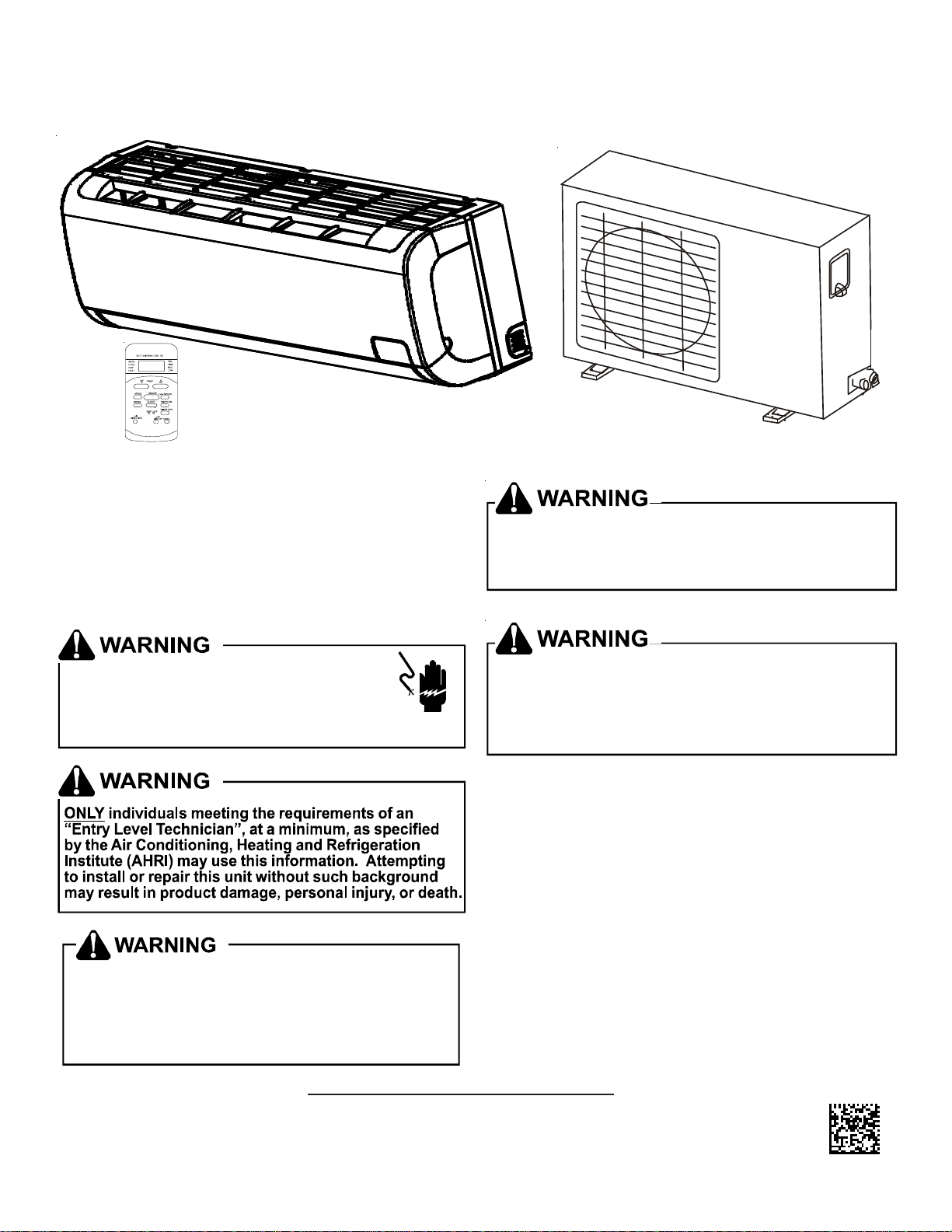
SPLIT TYPE ROOM AIR CONDITIONER AND HEAT PUMP MODELS
MSC/MSH 9,000 & 12,000 BTUH • 115 VOLT
O
Important Safety Instructions
The following symbols and labels are used throughout this
manual to indicate immediate or potential safety hazards. It is
the owner’s and installer’s responsibility to read and comply
with all safety information and instructions accompanying these
symbols. Failure to heed safety information increases the risk
of personal injury, property damage, and/or product damage.
T o prevent the r isk of property damage, personal injury, or
death, do not store combustible ma terials or use gasol ine
or other flammable liquids or vapor s in the vicinity of thi
appliance.
HIGH VOLTAGE!
Disconnect ALL power before servicing.
Multiple power sources may be present.
Failure to do so may cause property damage,
personal inju ry or deat h.
Goodman wi ll not be r esponsi ble fo r any in jur y or
proper ty da mag e ar i si ng fr om i mpr o per se r vic e o r
servic e proc ed ur es. If you pe rf orm s er vi ce on your
own produ ct , you assume r es pons i b ili t y f or an y
personal in ju r y or p ro pe rt y d ama ge whi c h ma y r es ul t.
T o prevent h eat releated illness or dea th, do not use th is
device for unattended cooli ng of persons or animals una ble
to react to product failure. Failure of unattended air
conditioner may result in ex treme heat in area intended
for cooling, causing heat-related ill ness or death of
persons or animals.
Shipping Inspection
Always keep the unit upright; laying the unit on its side or top
may cause equipment damage. Shipping damage, and subsequent investigation is the responsibility of the carrier. Verify
the model number, specifications, electrical characteristics,
and accessories are correct prior to installation. The distributor or manufacturer will not accept claims from dealers for transportation damage or installation of incorrectly shipped units.
IO-411
August 2011
© 2011 Goodman Manufacturing Company, L.P.
5151 San Felipe, Suite 500, Houston, TX 77056
www.goodmanmfg.com -or- www.amana-hac.com
Page 2
CONTENTS
Important Safety Instructions .............................................. 1
Shipping Inspection ............................................................ 1
Codes & Regulations ......................................................... 2
Installation Considerations ................................................. 2
Rooftop Installations ........................................................... 3
Tools .................................................................................. 3
Indoor Unit Installation ........................................................ 3
Outdoor Unit Installation ..................................................... 5
Refrigerant Pipe Connection ............................................... 6
Electrical ............................................................................ 7
Connect the Cable to the Indoor Unit .................................. 8
Connect the Cable to the Outdoor Unit ............................... 8
Leak Testing (Nitrogen or Nitrogen-Traced) ......................... 9
System Evacuation ............................................................ 9
Safe Refrigerant Handling ................................................. 10
Safety Check ................................................................... 10
Test Running ..................................................................... 11
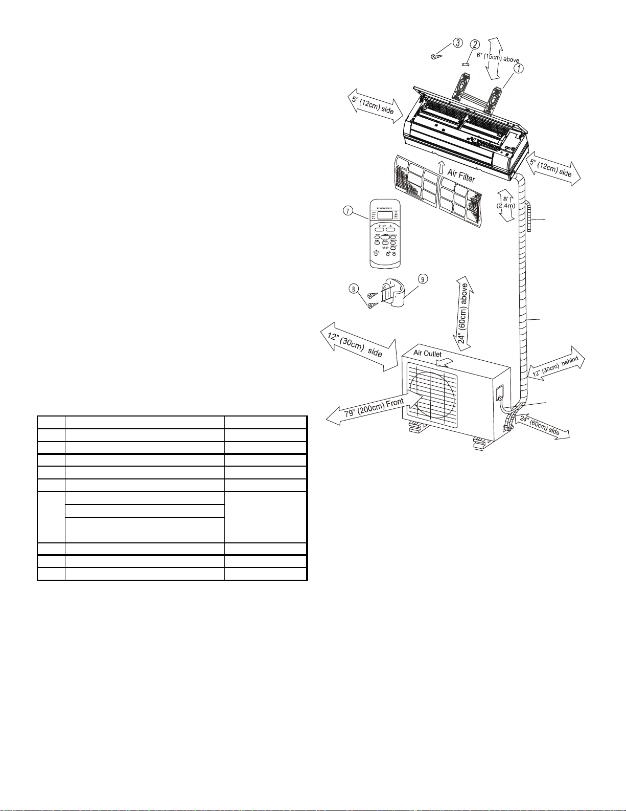
• Be sure that placement of the unit allows adequate condensate drainage.
• Do not install near a doorway.
• Ensure that the spaces indicated by the arrows is from
the wall, ceiling or other obstacles (See minimum clearances required in Figure 1.)
• Noise prevention should be considered when installing
the unit.
• Do not place the unit closer than 3 ft. (1m) to a TV or
radio.
• Consideration should be given to the distance from furniture, curtains, or other obstructions that will interfere with
the unit’s airflow.
• Do not exposure the unit direct sunlight. Exposure will
fade the cabinet and affect its appearance. Sunlight
prevention should be considered in placing the unit.
More than 6” (15 cm)
(to the ceiling)
Codes & Regulations
This product is designed and manufactured to comply with
national codes. Installation in accordance with such codes and/
or prevailing local codes/regulations is the responsibility of the
installer. The manufacturer assumes no responsibility for equipment installed in violation of any codes or regulations.
The United States Environmental Protection Agency (EPA)
has issued various regulations regarding the introduction and disposal of refrigerants. Failure to follow these
regulations may harm the environment and can lead to
the imposition of substantial fines. Should you have any
questions please contact the local office of the EPA.
Installation Considerations
To ensure that the unit operates safely and efficiently, it must
be installed, operated, and maintained according to these
installation and operating instructions and all local codes and
ordinances, or, in their absence, with the latest edition of the
National Electrical Code. The proper installation of this unit is
described in the following sections. Following the steps in the
order presented should ensure proper installation.
MOUNT WITH THE LOWEST MOVING PARTS AT
LEAST ABOVE FLOOR OR GRADE LEVEL.
2.4m (8 ft.)
More than
5”
(12cm)
More than 96” (2.4 m)
(to the floor)
More than
5”
(12cm)
Figure 1
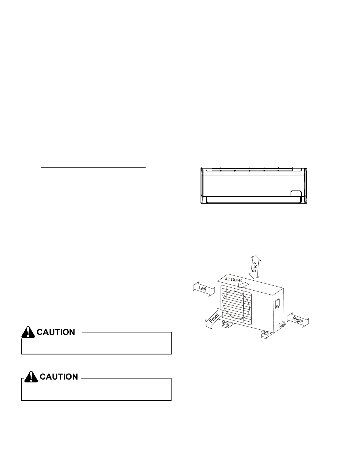
OUTDOOR UNIT
When placing the outdoor unit, consider any obstructions that
may constrict the air inlet or outlet. (See Figure 2).
More than
More than
12” (30cm)
More than
79” (200cm)
12” (30cm)
More than
24” (60cm)
Figure 2
INDOOR UNIT
T o avoid prop erty damage, personal inj ury or death due to
electrical shock, do not use an ext ension cord wit h this unit.
• Do not expose unit to excessive heat.
• Select a location where there are no obstructions in front
or the sides of the unit.
• Locate the outdoor unit in a location that will not obstruct discharge air from the condenser.
• Do not install outdoor unit in a corrosive environment.
• Keep the clearances from the wall or other obstacles as
indicated by the arrows on Figure 2.
• Do not place animals or plants in the path of the air inlet
or outlet.
2
Page 3
• Select a location where noise, vibration and hot discharged air will not be an issue.
• Do not install where high frequency equipment is used
(wireless equipment, welding machine, medical facility)
as it may interfere with the unit’s operation.
Rooftop Installations
If it is necessary to install the outdoor unit on a roof structure,
ensure the roof structure can support the weight and that proper
consideration is given to the weather-tight integrity of the roof.
Since the unit can vibrate during operation, sound vibration
transmission should be considered when installing the unit.
Vibration absorbing pads or springs can be installed between
the condensing unit legs or frame and the roof mounting assembly to reduce noise vibration.
Tools
Level gauge Gas leak detector
Screwdriver Vacuum pump
Electric drill, hole core drill (65mm) Gauge manifold
Flaring tool set Users manual
Torque wrenches Thermometer
1.8kgf.m 13 ft-lb Multimeter
4.2kgf.m 30 ft-lb Pipe cutter
5.5kgf.m 40 ft-lb Measuring tape
6.6kgf.m 48 ft-lb Spanner (half union)
Hexagonal wrench (4mm)
PARTS
No. Description Quantity
1 Installation Plate 1
2Clip Anchor 8
3 Self-tapping Screw A ST3.9x25 8
4 Seal (on selected models 1
5 Drain joint 1
*Con ne ctio n Pip e Ass e m b ly
6
Liquid Side 1/4" (Φ 6.35)
Gas Side 3/ 8" (Φ 9.52 )
1/2" (Φ12.7)
7 Remote Control 1
8 Self-tapping Screw B ST2.9x10 2
9 Remote Control holder 1
*Part s must be purcha s ed sep ara te ly . Con sult dealer for p ipe sizes.
(Minimum pipe wall thickness of 1/32" (0.7 mm) is recommended)
NOTE: Parts listed are provided with the unit except where
noted. Any additional parts required must be purchased separately.
*Se e
Note
O
Additional
Drain
Pipe
Wrapping
Ta pe
Loop the
connective
cable.
Figure 3
NOTE: Copper lines must be insulated independently.
IMPORTANT NOTES:
• A stud finder should be used to locate studs and prevent
unnecessary damage to the wall.
• A minimum pipe run of 10’ (3 meters) is required to minimize vibration and excessive noise.
Indoor Unit Installation
Installation of Mounting Bracket
1. Install the mounting bracket horizontally and securely to
the wall, allowing room for access on either side of the
unit.
2 If the wall is constructed of brick, concrete or similar
material, drill eight (8) 3/16” (5 mm) diameter holes in the
wall. Insert the clip anchor for appropriate mounting
screws.
3. Install the mounting bracket on the wall with eight (8)
type “A” screws.
3
Page 4
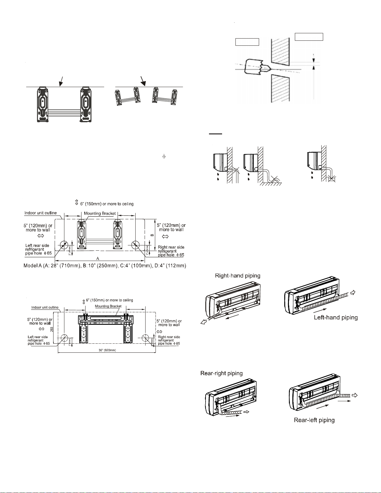
NOTE: Install the mounting bracket and drill the holes in the
wall according to the wall structure and the corresponding mounting points on the mounting bracket. (The
mounting brackets vary according to the model.)
Wall
Outdoor
Indoor
Correct orientation
of Installation Plate
Incorrect orientation
of Installation Plate
Figure 4
4. Determine the hole positions according to the diagram
detailed in Figures 5A & 5B. Drill one (1) 2.5” hole (
65mm),
slanting slightly to the outside.
NOTE: Always use wall hole conduit when drilling metal
grid, metal plate, etc.
C
D
5-7mm
3/16” -1/4”
Figure 6
Do NOT install drain hose as shown in Figure 7.
Do not block water flow by a rise.
Do not put the end of
drain hose into water.
Figure 7
6. When connecting extension drain hose, insulate the connecting part of the extension drain hose with a shield
pipe. Do not allow the drain hose to be slack.
7. REFRIGERANT PIPING INSTALLATION:: For the left-
hand and right-hand piping, remove the pipe cover from
the side panel. (Figure 8.)
Model B (A: 31” (790mm), B:10” (265mm), C:4” (100mm), D: 6” (151mm)
Figure 5A
6” (150mm)
7” (187mm)
Figure 5B
Refrigerant Piping & Condensate Piping
Installation:
5. Drain hose should be installed with a slight downward
slope. (See Figure 6.)
Figure 8
8. For the rear right-hand and rear left-hand piping, install as
shown in Figure 9.
Figure 9
To make refrigerant tube connections, refer to Tightening
Connection in the Refrigerant Piping Connection.
4
Page 5

Indoor Unit Installation
9. Pass the piping through the hole in the wall.
10. Place the upper claw on the back of the indoor unit on
the upper hook of the installation plate. Move the indoor
unit from side to side to ensure it is securely mounted.
(See Figure 10 ).
NOTE: By placing cushioning material between the in-
door unit and the wall, placement of piping is easier
(see Figure 11). REMOVE CUSHIONING MATERIAL
AFTER PIPING IS COMPLETED.
Upper Hook
Cushioning
Lower Hook
material
Figure 10 Figure 11
11. Push the lower part of the indoor unit up on the wall.
Move it from side to side, up and down to ensure the unit
is hooked securely.
Piping and wrapping
Evenly bundle the tubing, connecting cable and drain hose
securely with tape as shown in Figure 12.
Because the condensed water from the rear of the indoor unit
gathers in the drain pan and is piped out of the room, do not
put anything else in the drain pan.
Do not allow piping to hold indoor unit away
from the wall.
Never intertwine power wiring and other wiring.
Outdoor Unit Installation
Outdoor Installation precautions
• Install the outdoor unit on a rigid base to prevent noise
level and vibration.
• Place the outdoor unit in such a manner to minimize
restriction of discharge air.
Protect the unit from prevailing winds. To ensure the
unit operates correctly, place the unit lengthwise along
a wall or use a dust or shield plate.
Figure 13A
• If a wall mount installation is required, the installation
bracket should meet the requirement in the installation
bracket diagram and the wall should be able to support
the installation.
Figure13B
Figure 12
IMPORTANT NOTES:
• Indoor unit must be connected before the outdoor unit.
• Drain hose should not be allowed to become slack.
• Insulate both the auxiliary pipings.
• Ensure that the drain hose is positioned at the lowest
side of the bundled tubing. Positioning it at the upper
side can cause the drain pan to overflow inside the unit.
• Drain hose should be sloped downward to ensure condensate will drain correctly.
• Be sure there are no obstacles blocking air discharge.
The installation wall should be constructed of brick, concrete or another surface of equal strength to hold the
unit safely. Make sure the connections to the wall,
bracket and unit are firmly seated and there are no obstructions to the airflow.
Anchoring the outdoor unit
The unit should be tightly anchored, horizontally, with a nut
and bolt ( 10 or 8) on a concrete or similarly rigid, stable
surface.
5
Page 6

1
Figure 14A
H
2
W
1
W
2
Figure 14B
MS* 9 & MS*12
Outdoor
Un i t Dimensions
Inches/mm (L1xHxW1) L2 (mm) W2 (mm)
30" x 23" x 11"
760 x 590 x 285
Drain joint installation
NOTE: Drain joints differ slightly according to the different
outdoor units. Inspect your unit and use the installation instructions for your specific unit.
For drain joints with seals (Figure 15A):
• Slide the seal onto the drain joint and insert into the
base pan hole of the outdoor unit. Rotate 90° to secure
(see Figure 16).
For drain joints without seals (Figure 15B):
• Insert the drain joint into the base pan hole of the outdoor unit until it remains fixed, accompanied by a clicking sound.
NOTE: For protection against water condensation off the out-
door unit during heating mode, connect the drain joint with an
extension drain hose (provided by the installer)
Mounting Dime nsions
21"
530
11 1/2"
290
(Figure 15A) (Figure 15B)
Correct alignment
Incorrect alignment
Figure 16
Refrigerant Pipe Connection
NOTE: The main cause of refrigerant leaks is due to defective
flare connections.
Make flare connections using the following procedure:
1. Remove the flare nuts attached to the indoor and outdoor units. Before flaring, slide them over the tubing. It
is not possible to put them on after flaring tubes.
6
Page 7

2. Insert tube in flare tool to measurement “A” in chart.
Flare tubing as shown in Figure 19. Make sure flare is
free of burrs and completely formed to make a leak proof
joint.
NOTE: In order to avoid dropping burrs into the tubing,
angle the end of the copper tube/pipe in a downward
direction as you remove the burrs.
Pipe
Reamer
Point down
Figure 17
Outdoor
Diameter (mm)
1/4" (Φ 6.35)
3/8" (Φ 9.52)
1/2" (Φ12.7)
Tightening
Torque
(N. cm)
1500
(153kgf.cm)
2500
(255kgf.cm)
2500
(255kgf.cm)
Additional
Tightening
Torque (N. cm)
1600
(163kgf.cm)
2500
(265kgf.cm)
3600
(367kgf.cm)
Flare nut
Copper tube
Figure 18
4. Flare Connections: Firmly hold the copper pipe in a die
with the dimensions as in the following table.
Model
MS* 09 & 12
MS*09
MS*12
Outdoor
Diameter
(inches & mm)
1/4" (Φ 6.35) 3/64" (1.3) 1/32" (0.7)
3/8" (Φ 9.52) 1/16" (1.6) 3/64" (1.0)
1/2" (Φ12.7) 1/16" (1.8) 3/64" (1.0)
A (inches & mm)
Max. Min.
Handle
Bar
"A"
Bar
Yoke
Figure 20
Figure 21
Do not over-tighten. Excessive torque can
break the nut and/or crimp the pipe.
Electrical
Cone
Copper pipe
Clamp handle
Figure 19
Red arrow mark
5. Tightening the connection:
• Align the center of the pipes and finger-tighten the flare
nut. Using a spanner and torque wrench (Figures 20 &
21) continue tightening the flare nut until the nut is firmly
on the pipe.
HIGH V O LTAGE!
Disconne ct ALL power before se rvi c in g or
install ing thi s uni t . Mul t ip le po wer s our ce s
may be p res en t. Fa i lur e to do so may ca us e p rope rt y
damage, pe rs onal in ju ry or dea th due t o e le ctri c sho ck.
Wiring mus t c onf orm with NEC or CEC and al l loc al
codes. U nde rsiz e d wir es co uld c au se poo r e quipme nt
performance , eq ui pmen t dama ge or fire .
7
Page 8

IMPORTANT NOTES:
r
• If there are safety issues concerning the power supply,
the unit should not be connected until safety issues are
resolved.
• Ensure that the electrical power supply is sufficient to
safely power and run the unit.
• Power voltage should range for 90% - 110% of the rated
voltage.
• Main power switch and surge protector should be 1.5
times the capacity of the maximum current of the unit
and should be installed in the power circuit.
• The unit is to be grounded per NEC.
• Connect all wiring as shown in the Electrical Wiring Diagram located on the panel of the outdoor unit.
• All wiring must comply with local and national electrical
codes. Installation should be done by qualified electricians.
T o avoid the risk of personal injury, wiring to
the unit must be properly polarized and
grounded.
• This unit should have a individual branch circuit.
NOTE: The wire gauge and the current rating of the fuse or
breaker are determined by the minimum circuit ampacity and
maximum overcurrent protection device that is indicated on
the nameplate, located on the side panel of the unit. Refer to
the nameplate before selecting the wire, fuse and/or breaker.
Electrical box
cove
Figure 22
4. Ensure the color of the wires of the outdoor unit and the
terminal numbers are the same as the indoor unit’s.
5. Wrap the wires not connected with terminals with insulation tape, so they will not touch any electrical components. Secure the wires onto the control board with the
cord clamp.
Connect the Cable to the Outdoor Unit
1. Remove the electrical control board cover from the outdoor unit by loosening the screw as shown in Figure 23.
Connect the Cable to the Indoor Unit
NOTE: Before performing any electrical work, turn off the main
power to the system.
HIGH VOLTAGE!
Disconnect ALL power before servicing.
Multiple power sources may be present.
Failure to do so may cause property damage,
personal inju ry or deat h.
1. The inside and outside connecting wire can be connected
without removing the front grille.
2. Connecting wire between the indoor unit and outdoor unit
should be approved, polychloroprine sheathed, flexible
cord, type designation H07RN-F or heavier.
3. Lift up the indoor unit panel, remove the electrical box
cover by loosening the screw as show in Figure 22.
Figure 23
2. Connect the connective wires to the terminals, making
sure the numbers on the indoor unit match with the numbers on the outdoor unit’s terminal block. (See Models A
and B.)
8
Page 9

Terminals on the indoor unit
t
L N S
9. The means to disconnect from a power supply should be
incorporated in the fixed wiring and have an air gap contact separation of at least 1/8” (3 mm) in each active
(phase) conductor.
L N S
Model A
Terminals on the indoor uni
L N S
1(L) 2(N) S L N
Te r mi n a l s o n
the outdoor unit
Model B
3. Secure the wire onto the control board with the cord clamp.
4. To prevent the ingress of water, form a loop of the connective wires as illustrated in the installation diagram of
the indoor and outdoor units.
5. Insulate unused cords (conductors) with PVC-tape. Route
them so they do not touch any electrical or metal parts.
IMPORTANT NOTES:
After the above conditions have been met, ensure the following
notes are met:
1. A dedicated power circuit must be in place for the unit.
Wire the unit as shown in the circuit wiring diagram that
is posted inside the control cover.
2. Upon receipt of the unit, examine the screws fastening
the wiring in the casing of the electrical fittings, since
they may have become loose during transit. All must be
fastened securely to prevent arcing.
3. Specification of power source.
4. Confirm electrical capacity is sufficient for operation of
the unit.
Power
supply
Leak Testing (Nitrogen or Nitrogen-Traced)
Pressure test the system, using dry nitrogen and soapy water
to locate any leaks in the system. If you wish to use a leak
detector, charge the system to 10 psi using the appropriate
refrigerant, then use nitrogen to finish charging the system to
working pressure. Apply the detector to suspect areas. If
leaks are found, repair them. After repair, repeat the pressure
test. If no leaks exist, proceed to System Evacuation.
System Evacuation
Condensing unit liquid and suction valves are closed to contain
the charge within the unit. The unit is shipped with the valve
stems closed and caps installed. Do not open valves until
the system is evacuated.
1. Connect the vacuum pump with 250 micron capability to
the service valves.
2. Evacuate the system to 250 microns or less using suc-
tion AND liquid service valves. Using both valves is nec-
essary as some compressor create a mechanical seal
separating the sides of the system.
3. Close the pump valve and hold vacuum for 10 minutes.
Typically, pressure will rise during this period.
NOTES:
• If the pressure rises to 1000 microns or less and remains steady, the system is considered leak-free; proceed to start-up.
• If pressure rises above 1000 microns but hold steady
below 2000 microns, moisture and/or non-condensables
may be present or the system may have a small leak.
Return to step 2. If the same result is encountered,
check for leaks as previously indicated and repair as
necessary, then repeat evacuation.
• If pressure rises above 2000 microns, a leak is present.
Check for leaks as previous indicated and repair as necessary then repeat evacuation.
5. Maintain the starting voltage at more than 90% of the
rated voltage marked on the name plate.
6. Confirm the wire gauge is as specified in the power source
specification.
7. Always install an earth leakage circuit breaker in a wet or
moist area.
8. A drop in voltage may be caused by the vibration of a
magnetic switch, causing damage to the contact point,
fuse breakage, disturbance of the normal function of the
overload.
Connective
Pipe Length
Less than
More than
9
16' (5m)
16' (5m)
Evacuation
Method
Use
Vacuum Pu mp
Use
Vacuum Pu mp
Additional Amount of Refrigerant
to be Charged
---
R410A (Pipe Length-5) x 0.3 oz./ft. (20 g/m)
Pipe Length and Refrigerant Amount
Page 10

• When relocating the unit to another place, perform the
evacuation using a vacuum pump.
• Refrigerant added to the unit must be in liquid form. (Does
not apply to units using R-22.)
Use caution when handling the packed valve:
• Open the valve stem unit it comes in contact against the
stopper. Do not attempt to open further.
Safe Refrigerant Handling
While these items will not cover every conceivable situation,
they should serve as a useful guide.
WARNING
Refrigerants are hea vier than air. They can "push out"
the oxygen in your lungs or in any enclosed space.To
avoid possible difficulty in breathing or death:
•
Never purge refrigerant into an enclosed room or
space. By law, all refrigerants must be reclaimed.
•
If an indoor leak is suspected, throughly ventilate the
area b efor e begi nning work.
• Liquid refrigerant can be very cold. To avoid possible
frostbite or blindness, avoid contact and wear gloves
and goggles. If liquid refrigerant does contact your
skin or eyes, seek medical help immediately.
• Always follow EPA regulations. Never burn refrig erant, as poisonous gas will be produced.
WARNING
To avoid possible e x plosion:
•
Never apply flame or steam to a refrigerant cylinder.
If you must heat a cylinder for faster charging,
partially immerse it in wa rm water.
•
Never fill a cylinder more than 80% full of liquid re frigerant.
• Never add anything other than R-22 to an R-22 cy linder or R-410A to an R-410A cylinder. The service
equipment used must be listed or certified for the
type of refrigerant used.
• Store cylinders in a cool, dry place. Never use a cy linder as a platform or a roller.
C
D
B
Figure 24
• Securely tighten the valve stem cap with a spanner or
similar tool.
• See tightening torque table in Tightening Connection
section.
Safety Check
After completing the electrical installation:
1. Grounding: After grounding the unit, measure the grounding resistance by visually inspecting the unit and by using a grounding resistance tester, making sure the grounding resistance is less than 4.0 ohms.
2. Electrical leakage check (to be performed during operation): During the test operation after complete installation
of the unit, the qualified installer may use the electroprobe
and multimeter to perform the electrical leakage check.
Turn off the unit immediately if leakage occurs.
WARNING
To avoid possible explosion, use only returnable (not
disposable) service cylinders when removing refrigerant from a system.
• Ensure the cylinder is free of damage which could
lead to a leak or explosion.
• Ensure the hydrostatic test date does not excee d
5 years.
• Ensure the pressure rating meets or exceeds 400
lbs.
When in doubt, do not us e cylinder.
10
Page 11

Test Running
A
After completing the gas leak check at the flare nut connections and electrical safety check, perform the test operation.
• Ensure all tubing and wiring have been properly connected.
• Make sure both the gas and liquid side service valves
are fully open.
1. Connect the power; press the ON/OFF button on the remote control to turn the unit on.
2. Using the MODE button, select COOL, HEAT, AUTO and
FAN to ensure all the functions are operating.
3. When the ambient temperature is lower than 63°F (17°C),
the unit cannot be controlled by the remote control. To
run in cooling mode, operation can be done manually.
Manually controlling the unit is to be done only when the
remote control is disabled or maintenance is required.
• Grasp the panel sides and lift up the panel to an angle
where it remains fixed and a clicking sound is heard.
• Press the manual control button to select AUTO or COOL.
The unit will operate under forced AUTO or COOL mode
(see User’s manual for more details).
UTO/COOL
Figure 25
4. Test operation should last approximately 30 minutes.
11
Page 12

Goodman Manufacturing Company, L.P.
5151 San Felipe, Suite 500, Houston, TX 77056
www.goodmanmfg.com
© 2011 Goodman Manufacturing Company, L.P.
12
 Loading...