

Page 1
A
I
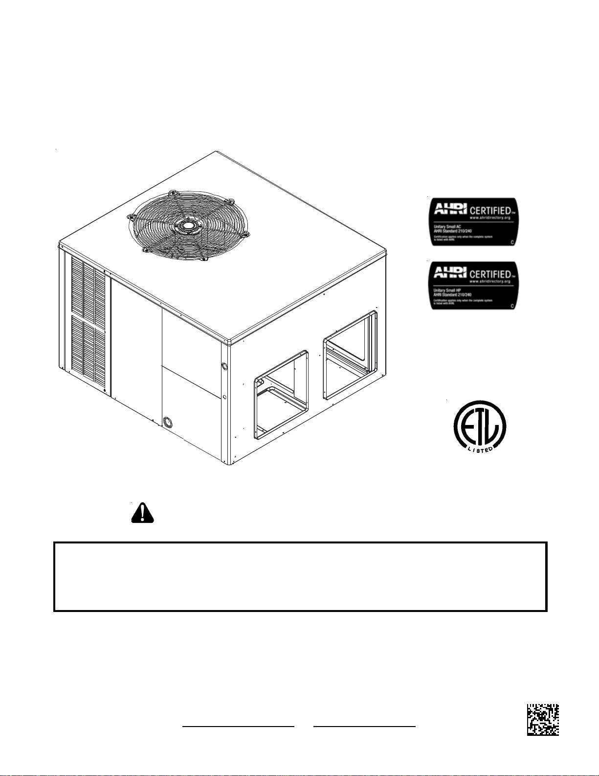
NSTALLATION INSTRUCTIONS
F
OR
S
IR
C
ONDITIONERS
ELF
-C
ONTAINED
AND
H
P
EAT
ACKAGE
P
GPC/GPH 13 SEER “M” SERIES
UMP
U
NITS
W
ITH
R-410A
RECOGNIZE THIS SYMBOL AS A SAFETY PRECAUTION.
ATTENTION INSTALLING PERSONNEL
Prior to installation, thoroughly familiarize yourself with this Installation Manual. Observe all safety warnings. During
installation or repair, caution is to be observed.
It is your responsibility to install the product safely and to educate the customer on its safe use.
These installation instructions cover the outdoor
installation of self contained package air conditioners
and heating units. See the Specification Sheets
applicable to your model for information regarding
accessories.
IO-395
8/10
Goodman Manufacturing Company , L.P.
5151 San Felipe, Suite 500, Houston, TX 77056
www.goodmanmfg.com www.amana-hac.com
© 2010 Goodman Manufacturing Company, L.P.
®
C
*NOTE: Please contact your distributor or our
website for the applicable Specification Sheets
referred to in this manual.
US
Page 2
INDEX
TO THE INSTALLER ................................................2
O THE OWNER ...................................................2
T
SHIPPING INSPECTION ..........................................3
REPLACEMENT PARTS ..........................................3
RDERING PARTS ..................................................3
O
SAFETY INSTRUCTIONS ........................................3
CODES AND REGULATIONS..................................3
EP A R
N
MAJOR COMPONENTS ..........................................4
PRE-INSTALLATION CHECKS................................4
C
U
G
R
R
R
CIRCULA TING AIR AND FILTERS...........................5
A
D
F
PIPING.......................................................................6
C
WIRING......................................................................7
H
L
I
STARTUP, ADJUSTMENTS, AND CHECKS ........... 8
S
H
F
COMPONENTS ........................................................8
C
C
C
C
C
D
O
R
I
B
HEAT PUMP OPERATION ....................................... 9
C
H
D
S
A
S
EGULATIONS ................................................4
A TIONAL CODES ..................................................4
LEARANCES AND ACCESSIBILITY ..............................4
NIT LOCATION ......................................................4
ROUND LEVEL PRE-INSTALLATION DETAILS ...............4
OOF TOP PRE-INSTALLATION DETAILS .....................4
OOF CURB INSTALLATIONS ONLY ............................5
IGGING DETAILS ..................................................5
IRFLOW CONVERSION ...........................................5
UCT WORK ..........................................................6
ILTERS ...............................................................6
ONDENSATE DRAIN ...............................................6
IGH VOLTAGE WIRING ...........................................7
OW VOLTAGE WIRING ............................................7
NTERNAL WIRING...................................................7
TART-UP PROCEDURE AND CHECKLIST .....................8
EAT PUMP START-UP PROCEDURE ..........................8
INAL SYSTEM CHECKS ..........................................8
ONTACT OR ..........................................................8
RANKCASE HEATER ..............................................9
ONDENSER MOTOR ..............................................9
OMPRESSOR .......................................................9
ONT ACTOR RELAY ................................................9
EFROST CONTROL................................................9
UTDOOR THERMOST AT ..........................................9
EVERSING VALVE COIL .........................................9
NDOOR BLOWER MOTOR ........................................9
LOWER INTERLOCK RELAY .....................................9
OOLING CYCLE ...................................................9
EA TING CYCLE ....................................................9
EFROST CONTROL..............................................10
UGGESTED FIELD TESTING/TROUBLE SHOOTING ......10
IRFLOW MEASUREMENT AND ADJUSTMENT ...............10
PEED TAP ADJUSTMENTS
FOR INDOOR BLOWER MOTOR ...........................12
EFRIGERANT CHARGE CHECKS.............................12
R
ELECTRICAL ADJUSTMENTS ..............................12
MAINTENANCE ......................................................13
ERVICE ............................................................13
S
NADEQUATE AIR VOLUME THROUGH INDOOR COIL .....13
I
UTSIDE AIR INTO RETURN DUCT ..........................13
O
NDERCHARGE ....................................................13
U
OOR “TERMINATING” SENSOR CONTACT ................13
P
ALFUNCTIONING REVERSING VALVE -
M
HIS MAY BE DUE TO: .......................................13
T
TROUBLESHOOTING CHART .............................14
APPENDIX...............................................................15
UNIT DIMENSIONS ................................................15
MINIMUM CLEARANCES ...................................... 16
RECOMMENDED FILTER SIZES ..........................16
WARNING
I
NSTALLATION AND REPAIR OF THIS UNIT SHOULD BE
PERFORMED
THE REQUIREMENTS OF AN
SPECIFIED
R
EFRIGERATION INSTITUTE
INSTALL
RESUL T
ONLY BY
BY
THE AIR-CONDITIONING
OR
REPAIR THIS UNIT WITHOUT SUCH BACKGROUND MAY
IN
PRODUCT DAMAGE, PERSO NAL INJURY OR DEATH
INDIVIDUALS MEETING
“E
NTRY LEVEL TECHNICIAN” AS
, H
(AHRI). A
EATING, AND
TTEMPTING TO
AT A MINIMUM
(
)
.
TO THE INSTALLER
Carefully read all instructions for the installation prior to installing
unit. Make sure each step or procedure is understood and any
special considerations are taken into account before starting installation. Assemble all tools, hardware and supplies needed to
complete the installation. Some items may need to be purchased
locally. After deciding where to install unit, closely look the location
over - both the inside and outside of home. Note any potential
obstacles or problems that might be encountered as noted in this
manual. Choose a more suitable location if necessary.
IMPORTANT NOTE: If a crankcase heater is used, the unit
should be energized 24 hours prior to compressor start up to
ensure crankcase heater has sufficiently warmed the compressor. Compressor damage may occur if this step is not followed.
IMPORTANT NOTE TO THE OWNER REGARDING PRODUCT
WARRANTY
Y our warranty certificate is supplied as a separate document
with the unit installed by your contractor. Read the limited
warranty certificate carefully to determine what is and is not
covered and keep the warranty certificate in a safe place. If
you are unable to locate the warranty certificate please contact
your installing contractor or contact customer service (877254-4729) to obtain a copy .
IMPORTANT: T o receive the 10-year Parts Limited W arranty ,
online registration must be completed within 60 days of
installation. Online registration is not required in California or
Quebec.
To register your Goodman brand unit, go to
www.goodmanmfg.com. Click on the word “W arranty” located
on the left side of the home page. Next, click on the word
2
Page 3
“Product Registration” located on the left side of the Warranty
page and complete the forms in the manner indicated on the
Product Registration page.
Product limited warranty certificates for models currently in
production can be viewed at www.goodmanmfg.com. If your
model is not currently in production or does not appear on the
website, please contact your installing contractor or contact
customer service (877-254-4729) to obtain a copy of your
warranty certificate.
Each product overview page contains a Product Warranty link;
by clicking on it you will be able to view the limited warranty
coverage for that specific product. T o view warranty registration
information, click on the Product Warranty text on the left
navigation panel on the home page of each website. The Online
Product Registration pages are located in this same section.
Before using this manual, check the serial plate for proper
model identification.
The installation and servicing of this equipment must be
performed by qualified, experienced technicians only .
WARNING
HIGH VOLTAGE!
DISCONNECT ALL POWER BEFORE SERVICING OR INSTALLING
THIS UNIT.
TO DO SO MAY CAUSE PROPERTY DAMAGE, PERSONAL INJURY OR
DEATH.
MULTIPLE POWER SOURCES MAY BE PRESENT. FAILURE
WARNING
CONNECTING UNIT DUCT WORK TO UNAUTHORIZED HEAT PRODUCING DEVICES
SUCH AS A FIREPLACE INSERT, STOVE, ETC. MAY RESULT IN PROPERTY
DAMAGE, FIRE, CARBON MONOXIDE POISONING, EXPLOSI ON, PERSONAL
INJURY OR DEATH.
WARNING
HIS PRODUCT CO NTAINS OR PRODUCES A CHEMICAL OR CHEMICALS WHICH
T
MAY CAUSE SERIOUS ILLNESS OR DEATH AND WHICH ARE KNOWN TO THE
S
TATE OF CALIFORNIA TO CAUSE CANCER, BIRTH DEFECTS OR OTHER
REPRODUCTIVE HARM.
SHIPPING INSPECTION
Upon receiving the unit, inspect it for damage from shipment.
Claims for damage, either shipping or concealed, should be filed
immediately with the shipping company. Check the unit model
number, specifications, electrical characteristics and accessories
to determine if they are correct. In the event an incorrect unit is
shipped, it must be returned to the supplier and must NOT be
installed. The manufacturer assumes no responsibility for installation of incorrectly shipped units.
REPLACEMENT PARTS
ORDERING PARTS
When reporting shortages or damages, or ordering repair parts,
give the complete unit model and serial numbers as stamped on
the unit’s nameplate.
Replacement parts for this appliance are available through your
contractor or local distributor. For the location of your nearest
distributor, consult the white business pages, the yellow page
section of the local telephone book or contact:
CONSUMER AFF AIRS
GOODMAN MANUFACTURING COMP ANY, L.P.
7401 SECURITY WA Y
HOUSTON, TEXAS 77040
877-254-4729
WARNING
O AVOID PROPERTY DAMAGE, PERSONAL INJURY OR DEATH, DO NOT USE
T
I
THIS UNIT IF ANY PART HAS BEEN UNDER WATER.
QUALIFIED SERVICE TECHNICIAN TO INSPECT THE FURNACE AND TO REPLACE
ANY PART OF THE CONTROL SYSTEM AND ANY GAS CONTROL HAVING BEEN
UNDER WATER.
MMEDIATELY CALL A
WARNING
TO PREVENT THE RISK OF PROPERTY DAMAGE, PERSONAL INJURY, OR DEATH,
DO NOT STORE COMBUSTIBLE MATERIALS OR USE G ASOLINE OR OTHER
FLAMMABLE LIQUIDS OR VAPORS IN THE VICINITY OF THIS APPLIANCE.
CODES AND REGULATIONS
SAFETY INSTRUCTIONS
The following symbols and labels are used throughout this manual
to indicate immediate or potential safety hazards. It is the owner’s
and installer’s responsibility to read and comply with all safety
information and instructions accompanying these symbols. Failure to heed safety information increases the risk of personal injury,
property damage, and/or product damage.
WARNING
DO NOT CONNECT TO OR USE ANY DEVICE THAT IS NO T DESIGN-CERTIFIED
BY
GOODMAN FOR USE WITH THIS UNIT. SERIOUS PROPERTY DAMAGE,
PERSONAL INJURY, REDUCED UNIT PERFORMANCE AND/
CONDITIONS MAY RESULT FROM THE USE OF SUCH NON-APPROVED DEVICES.
OR HAZARDOUS
The GPC/GPH M-series air conditioners and heat pumps are designed for OUTDOOR USE ONLY. GPH M-Series is available in
cooling capacities of 2, 2-1/2, 3, 3-1/2, 4 and 5 nominal tons of
cooling. GPC M-Series is available in cooling capacities of 3, 4
and 5 nominal tons of cooling. Optional field installed heat kits are
available in 5,8,10,15 and 20 kW. 3 phase heat kits are available
only in 15 and 20 kW. The units can be easily installed in manufactured or modular homes with existing high-static duct work. The
units can also be easily converted to accommodate a plenum for
normal or low-static applications. The GPC/GPH M-series are self
contained packaged units so the only connections needed for installation are the supply and return ducts, the line and low voltage
wiring and drain connection. The units are ETL listed and AHRI
certified.
3
Page 4
The information on the rating plate is in compliance with the FTC
& DOE rating for single phase units. The three phase units in
this series are not covered under the DOE certified program. The
efficiency ratings of these units are a product of thermal efficiency determined under continuous operating conditions independent of any installed system.
EPA REGULATIONS
IMPORTANT: THE UNITED STATES ENVIRONMENTAL PROTECTION
AGENCY (EP A) HAS ISSUED VARIOUS REGULATIONS REGARDING
INTRODUCTION AND DISPOSAL OF REFRIGERANTS IN THIS UNIT.
THE
FAILURE TO FOLLOW THESE REGULATIONS MAY HARM THE
ENVIRONMENT
. BECAUSE REGULATIONS MAY VARY DUE TO PASSAGE OF
FINES
LAWS, WE SUGGEST A CERTIFIED TECHNICIAN PERFORM ANY
NEW
WORK
PLEASE
AND CAN LEAD TO THE IMPOSITION OF SUBSTANTIAL
DONE ON THIS UNIT. SHOULD YOU HAVE ANY QUESTIONS
CONTACT THE LOCAL OFFICE OF THE EPA.
Allow 18” minimum for service access to the compressor compartment and controls. The top of the unit should be completely
unobstructed. If units are to be located under an overhang, there
should be a minimum of 36” clearance and provisions made to
deflect the warm discharge air out from the overhang.
UNIT LOCATION
Consider the affect of outdoor fan noise on conditioned space and
any adjacent occupied space. It is recommended that the unit be
placed so that condenser air discharge does not blow toward
windows less than 25 feet away. Consideration should also be
given to shade and unit appearance.
Heat pumps require special location consideration in areas of heavy
snow accumulation and/or areas with prolonged continuous subfreezing temperatures. Heat pump unit bases have holes under the
outdoor coil to permit drainage of defrost water accumulation. The
unit must be situated to permit free unobstructed drainage of the
defrost water and ice. A minimum 2" clearance under the outdoor
coil is required in the milder climates.
NATIONAL CODES
This product is designed and manufactured to permit installation
in accordance with National Codes. It is the installer’s responsibility to install the product in accordance with National Codes and/
or prevailing local codes and regulations.
MAJOR COMPONENTS
The unit includes a hermetically sealed refrigerating system (consisting of a compressor, condenser coil, evaporator coil with
flowrator), an indoor blower, a condenser fan and all necessary
internal electrical wiring. The heat pump also includes a reversing valve, solenoid, defrost thermostat and control and loss of
charge protection. The system is factory-evacuated, charged and
performance tested. Refrigerant amount and type are indicated
on rating plate.
PRE-INSTALLATION CHECKS
Before attempting any installation, the following points should
be considered:
• Structural strength of supporting members
• Clearances and provision for servicing
• Power supply and wiring
• Air duct connections
• Drain facilities and connections
• Location may be on any four sides of a home,
manufactured or modular, to minimize noise
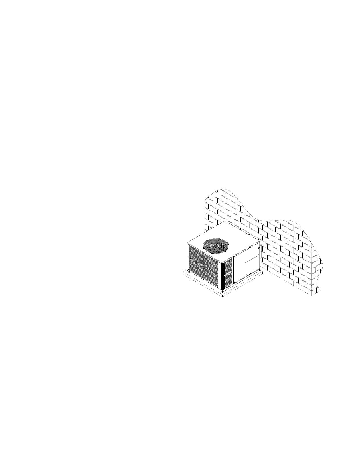
CLEARANCES AND ACCESSIBILITY
The unit is designed to be located outside the building with unobstructed condenser air inlet and discharge. Additionally, the
unit must be situated to permit access for service and installation. Condenser air enters from three sides. Air discharges
upward from the top of the unit. Refrigerant gauge connections
are made on the right side of the unit as you face the compressor
compartment. Electrical connections can be made either on the
right, bottom or duct panel side of the unit. The best and most
common application is for the unit to be located 10” from wall (4”
minimum) with the connection side facing the wall. This “close
to the wall” application minimizes exposed wiring.
Close to the wall application assures free, unobstructed air to
the other two sides. In more confined application spaces, such
as corners provide a minimum 10” clearance on all air inlet sides.
GROUND LEVEL PRE-INSTALLATION DETAILS
The unit should be set on a solid, level foundation - preferably a
concrete slab at least 4 inches thick. The slab should be above
ground level and surrounded by a graveled area for good drainage.
Any slab used as a unit’s foundation should not adjoin the building
as it is possible that sound and vibration may be transmitted to the
structure.
Ground Level Installation
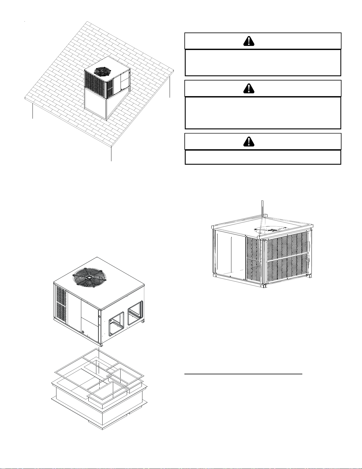
ROOF TOP PRE-INSTALLATION DETAILS
Ensure that the roof is weather tight and allows proper drainage of
condensation. Use steel or treated wood beams as unit support
for load distribution.
NOTE: To ensure proper condensate drainage, unit must be installed in a level position.
• To avoid possible property damage or personal injury, the
roof must have sufficient structural strength to carry the
weight of the unit(s) and snow or water loads as required
by local codes. Consult a structural engineer to determine
the weight capabilities of the roof.
• The unit may be installed directly on wood floors or on
Class A, Class B, or Class C roof covering material.
• To avoid possible personal injury, a safe, flat surface for
service personnel should be provided.
4
Page 5
Rooftop Installation
ROOF CURB INSTALLATIONS ONLY
NOTE: Sufficient structural support must be determined prior to
locating and mounting the curb and package unit.
RIGGING DETAILS
WARNING
O PREVENT PROPERTY DAMAGE, THE UNIT SHOULD REMAIN IN AN UPRIGHT
T
POSITION DURING ALL RIGGING AND MOVING OPERATIONS.
LIFTING AND MOVING WHEN A CRANE IS USED, PLACE THE UNIT IN AN
ADEQUATE CABLE SLING.
T
O FACILITATE
WARNING
O AVOID POSSIBLE PROPERTY DAMAGE, PERSONAL INJURY OR DEATH,
T
ENSURE THE ROOF HAS SUFFICIENT STRUCTURAL STRENGTH TO CARRY THE
WEIGHT OF THE UNIT(S), ROOF CURB, SNOW LOADS, AND WATER LOADS AS
REQUIRED BY LOCAL CODES.
DETERMINE THE WEIGHT CAPABILITIES OF THE ROOF.
CONSULT A STRUCTURAL ENGINEER TO
CAUTION
O AVOID POSSIBLE PERSONAL INJURY, A SAFE, FLAT SURFACE FOR SERVICE
T
PERSONNEL SHOULD BE PROV IDED.
IMPORTANT: If using bottom discharge with roof curb, duct work
should be attached to the curb prior to installing the unit.
Lower unit carefully onto roof mounting curb. While rigging unit,
center of gravity will cause condenser end to be lower than supply
air end.
Curb insulation, cant strips, flashing and general roofing material
are furnished by the contractor.
Curbing must be installed in compliance with the National Roofing
Contractors Association Manual. Construct duct work using current
industry guidelines. The duct work must be placed into the roof
curb before mounting the package unit.
Rigging
CIRCULATING AIR AND FILTERS
AIRFLOW CONVERSION
Units can easily be converted from horizontal to down-discharge
airflow delivery. In down-discharge or high static installations, the
installer should measure the total external static and review the
blower performance charts before performing the installation. In
some installations it will be necessary to change the blower speed
to provide proper air flow.
Horizontal Air Flow (Applies to 3 phase models)
Single phase models are shipped without horizontal duct
covers. If needed, these kits may be ordered through
Goodman’s Service Parts department.
Roof Curb Installation
5
Page 6

Remove these covers
for horizontal duct
applications
Return
Supply
Remove these panels
for downflow duct
applications
Duct Cover Installation
Down Discharge Applications
Cut insulation around bottom openings and remove panels from
the bottom of the unit, saving the screws holding the panels in
place.
NOTE: Single phase models require installation of horizontal duct
kit #20464501PDGK (medium chassis) and #20464502PDGK
(large chassis).
DUCT WORK
Duct systems and register sizes must be properly designed for
the C.F.M. and external static pressure rating of the unit. Duct work
should be designed in accordance with the recommended methods
of Air Conditioning Contractors of America Manual D (Residential)
or Manual Q (Commercial). All ductwork exposed to the outdoors
must include a weatherproof barrier and adequate insulation.
A duct system should be installed in accordance with Standards of
the National Board of Fire Underwriters for the Installation of Air
Conditioning, Warm Air Heating and Ventilating Systems. Pamphlet s
No. 90A and 90B.
The supply duct from the unit through a wall may be installed
without clearance. However, minimum unit clearances as shown
in the appendix must be maintained. The supply duct should be
provided with an access panel large enough to inspect the air
chamber downstream of the heat exchanger. A cover should be
tightly attached to prevent air leaks.
For duct flange dimensions on the unit refer to the Unit Dimension
illustration in the appendix.
For down-discharge applications, the ductwork should be attached
to the roof curb prior to installing the unit. Duct work dimensions are
shown in the roof curb installation manual.
If desired, supply and return duct connections to the unit may be
made with flexible connections to reduce possible unit operating
sound transmission.
FILTERS
CAUTION
T
O PREVENT PRO PERTY DAMAG E DUE TO FIRE AND LOSS O F
EQUIPMENT EFFICIENCY OR EQUIPMENT DAMAGE DUE TO DUST AND LINT
BUILD UP ON INTERNAL PARTS, NEVER OPERATE UNIT WITHOUT AN AIR
FILTER INSTALLED IN THE RETURN AIR SYSTEM.
Filters are not provided with unit and must be supplied and externally installed in the return duct system by the installer . An optional
factory approved internal filter rack may also be used. A field-installed filter grille is recommended for easy and convenient access to the filters for periodic inspection and cleaning. When
installing filters, ensure the air flow arrows on the filter are pointing
toward the circulator blower.
Refer to the unit filter size chart below for filter size information.
MINIMUM FILTER SIZE
NOMINAL SIZE (INCHES) NOMINAL AREA (SQ. FT.)
10x20 1.4
14x20 1.9
14x25 2.4
15x20 2.1
16x20 2.2
16x25 2.8
20x20 2.8
20x25 3.5
25x25 4.3
NOTE: Filters must have adequate face area for the rated quantity
of the unit. See the air delivery table below for recommended filter
size. Size the filters in accordance with their manufacturer recommendations. Throwaway filters must be sized for a maximum face
velocity of 300 feet per minute.
7
a
e
r
6
t
A
e
r
e
e
t
F
l
5
i
e
F
r
l
a
a
u
n
4
q
i
S
m
o
N
3
B
A
S
O
P
S
I
D
R
E
T
L
I
F
E
L
P
N
E
N
A
M
R
E
R
E
T
L
I
F
T
2
500 1000 1500 2000 2500 3000 3500
Airflow - SCFM
PIPING
CONDENSATE DRAIN
The condensate drain connection of the evaporator is a half coupling of ¾” N.P.T. A trap must be provided to have Proper condensate drainage.
Unit
Drain
Connection
Flexible
Tubing-Hose
Or Pipe
Install condensate drain trap as shown. Use ¾ “ drain connection
size or larger. Do not operate without trap. Unit must be level or
slightly inclined toward drain.
6
2" Minimum
3" Minimum
A Positive Liquid Seal
Is Required
Page 7

WIRING
NOTE: All wiring should be made in accordance with the National
Electrical Code.
Consult your local Power Company to determine the availability of
sufficient power to operate the unit. Check the voltage, frequency,
and phase at the power supply to ensure it corresponds to the unit’s
RATED VOL T AGE REQUIREMENT .
In accordance with the N.E.C. or local codes, install a branch circuit fused disconnect near the unit. Determine wire sizes and
overcurrent protection from the unit nameplate ampacity and in
accordance with the Minimum Filter Size or the N.E.C. The wiring
should never be sized smaller than is recommended by either of
these two sources.
Fuses smaller than that recommended on the rating plate could
result in unnecessary fuse failure or service calls. The use of
protective devices of larger size than indicated could result in extensive damage to the equipment. The manufacturer bears no
responsibility for damage caused to equipment as result of the
use of larger than is recommended size protective devices.
All units have undergone a run test prior to packaging for shipment. This equipment has been started at minimum rated voltage
and checked for satisfactory operation. Do not attempt to operate
this unit if the voltage is not within the minimum and maximum
voltages shown on nameplate.
All exterior wiring must be within approved weatherproof conduit.
The unit must be permanently grounded in accordance with local
codes, or in absence of local codes, with N.E.C ANSI/ NFPA NO.
70-1984 or latest edition by using ground lug in the control box.
Fuses or HACR type circuit breakers may be used where codes
permit.
FOR INTERNAL WIRING SEE WIRING LABEL ATTACHED TO UNIT
HIGH VOLTAGE WIRING
• Single Phase- T wo leads should be connected to terminals
L1 & L2 in the electrical control section, using wire sizes
specified in wiring table.
• Three Phase- Three leads should be connected to
terminals L1, L2 and L3 in the electrical section, using
wire sizes specified in wiring table.
LOW VOLTAGE WIRING
• Air Conditioners- Connect 24V wires from the thermostat
to the corresponding wires in the control box using No. 18
AWG as follows:
LEAD THERMOSTAT
Red R (24V)
Green G (Fan)
Yellow Y (Cool)
White W1 (Heat)*
Brown W2 (Heat)*
• Heat Pumps- Connect 24V wires from the thermostat to
the corresponding wires in the control box using No. 18
AWG as follows:
G
*NOTE:
LOW VOLTAGE CONNECTORS do not apply to heat pumps with
electric heat. LOW VOLTAGE CONNECTORS apply ONLY to GPC units
with electric h e at.
IMPORTANT NOTE: Some single phase units are equipped with a
single-pole contactor. Exercise caution when servicing as only one
leg of the power supply is broken with the contractor.
To wire the unit, make the following high and low voltage connections.
See
*NOTE
G
TERMINAL THERMOSTAT
Red R (24V)
Green G (Fan)
Orange O (Rev. Valve)
White W1 (Heat, 2nd)*
Brown W2 (Heat 3rd)*
Yellow Y (Cool)
C (Blue) C (Common)
*Optional field installed heat connections
INTERNAL WIRING
A diagram detailing the internal wiring of this unit is located on the
electrical box cover. If any of the original wire supplied with the appliance must be replaced, the wire gauge and insulation must be
the same as the original wiring.
Transformer is wired for 230 volts on the 208/230 models. See wiring diagram for 208 volt wiring.
1. For branch circuit wiring (main power supply to unit
disconnect), the minimum wire size for the length of run
can be determined using the circuit ampacity found on the
unit rating plate and the table below. From the unit
disconnect to unit, the smallest wire size allowable may be
used for the ampacity , as the Disconnect must be in sight
of the unit.
7
Page 8

BRANCH CIRCUIT AMPA CITY
SUPPLY WIRE LENGTH -
FEET
200 64443322
150 86644433
100 108866644
50 141210108866
15 20 25 30 35 40 45 50
2. Wire size based on 60° C rated wire insulation and 30° C
Ambient Temperature (86° F).
3. For more than 3 conductors in a raceway or cable, see the
N.E.C. for derating the ampacity of each conductor.
STARTUP, ADJUSTMENTS, AND CHECKS
WARNING
HIGH VOLTAGE!
DISCONNECT ALL POWER BEFORE SERVICING OR INSTALLING
THIS UNIT.
TO DO SO MAY CAUSE PROPERTY DAMAGE, PERSONAL INJURY OR
DEATH.
START-UP PROCEDURE AND CHECKLIST
With power turned off at all disconnects:
1. Turn thermostat system switch to “COOL” and fan switch
2. Inspect all registers and set them to the normal open
3. Turn on the electrical supply at the disconnect.
4. Turn the fan switch to the “ON” position. The blower should
5. Turn the fan switch to “AUTO” position. The blower should
6. Slowly lower the cooling temperature until the unit starts.
7. Turn the temperature setting to the highest position,
8. Turn the thermostat system switch to “OFF” and disconnect
HEAT PUMP START-UP PROCEDURE
1. Check the cooling mode for the heat pump in the same
2. Turn the thermostat system switch to “HEA T” and fan switch
MULTIPLE POWER SOURCES MAY BE PRESENT. FAILURE
to “AUTO”. Next, turn the temperature setting as high as it
will go.
position.
operate after a 7-second delay.
stop after a 65-second delay.
The compressor, blower and fan should now be operating.
Allow the unit to run 10 minutes, make sure cool air is being
supplied by the unit.
stopping the unit. The indoor blower will continue to run for
65-seconds.
all power when servicing the unit.
manner as above. The reversing valve is energized when
the thermostat is placed in the cooling position. A clicking
sound should be noticeable from the reversing valve. By
lowering the temperature setting to call for cooling, the
contractor is energized. The compressor, blower and fan
should then be running. Af ter the cooling mode is checked
out, turn the thermostat system switch to “OFF”.
to “AUTO”.
3. Slowly raise the heating temperature setting. When the
heating first stage makes contact, stop raising the
temperature setting.. The compressor, blower and fan
should now be running with the reversing valve in the deenergized (heating) position. After giving the unit time to
settle out, make sure the unit is supplying heated air.
4. If the outdoor ambient is above 80°F, the unit may trip on its
high pressure cut out when on heating. The compressor
should stop. The heating cycle must be thoroughly
checked, so postpone the test to another day when
conditions are more suitable. DO NOT FAIL TO TEST.
5. If the outdoor ambient is low and the unit operates properly
on the heating cycle, you may check the pressure cutout
operation by blocking off the indoor return air until the unit
trips.
6. If unit operates properly in the heating cycle, raise the
temperature setting until the heating second stage makes
contact. Supplemental resistance heat, if installed should
now come on. Make sure it operates properly.
NOTE: If outdoor thermostats are installed, the outdoor
ambient must be below the set point of these thermostats
for the heaters to operate. It may be necessary to jumper
these thermostats to check heater operation if outdoor
ambient is mild.
7. For thermostats with emergency heat switch, return to step
6. The emergency heat switch is located at the bottom of
the thermostat. Move the switch to emergency heat. The
heat pump will stop, the blower will continue to run, all
heaters will come on and the thermostat emergency heat
light will come on. 3-phase models are single stage heat
only.
8. If checking the unit in the wintertime, when the outdoor coil
is cold enough to actuate the defrost control, observe at
least one defrost cycle to make sure the unit defrosts
completely.
FINAL SYSTEM CHECKS
1. Check to see if all supply and return air grilles are adjusted
and the air distribution system is balanced for the best
compromise between heating and cooling.
2. Check for air leaks in the ductwork.
3. See Sections on Air Flow Measurement and Adjustment
and Checking Charge.
4. Make sure the unit is free of “rattles”, and the tubing in the
unit is free from excessive vibration. Also make sure tubes
or lines are not rubbing against each other or sheet metal
surfaces or edges. If so, correct the trouble.
5. Set the thermostat at the appropriate setting for cooling
and heating or automatic changeover for normal use.
6. Be sure the Owner is instructed on the unit operation,
filter, servicing, correct thermostat operation, etc.
The foregoing “Start-up Procedure and Check List” is recommended to serve as an indication that the unit will operate normally.
COMPONENTS
Contactor
This control is activated (closed) by the room thermostat for both
heating and cooling. The contactor has a 24V coil and supplies
power to the compressor and outdoor fan motor.
8
Page 9

Crankcase Heater
This item is “ON” whenever power is supplied to the unit and the
crankcase heater thermostat is closed. Crankcase heater
thermostat closes at 67° and opens at 85°. It warms the compressor
crankcase thereby preventing liquid migration and subsequent
compressor damage. The insert type heater is self regulating. It is
connected electrically to the contactor L1 and L2 terminals.
Condenser Motor
This item is activated by the contactor during heating and cooling,
except during defrost and emergency heat operation.
Compressor
This item is activated by the contactor for heating and cooling,
except during emergency heat. It is protected by an internal overload.
Contactor Relay
This control is activated by the thermostat (24V coil) and supplies
power to the contactor.
Defrost Control
The Defrost control provides time/temperature initiation and termination of the defrost cycle. When a Defrost cycle is initiated, the
defrost control shifts the reversing valve to “COOLING” mode, stops
the outdoor fan and brings on supplemental heat. Normally, a
Defrost cycle will take only 2-3 minutes unless system is low on
charge or outdoor conditions are severe. (windy and cold). The
defrost control also provides for a 3 minute off cycle compressor
delay.
Outdoor Thermostat
These optional controls are used to prevent full electric heater
operation at varying outdoor ambient (0° F-to 45° F). They are normally open above their set points and closed below to permit staging of indoor supplement heater operation. If the outdoor ambient
temperature is below 0° F (-18° C) with 50% or higher RH, an
outdoor thermostat (OT) must be installed and set at (0°) on the
dial. Failure to comply with this requirement may result in damage
to the product which may not be covered by the manufacturer’s
warranty .
Reversing Valve Coil
This coil is activated by the thermostat, in the cooling mode and
during defrost. It positions the reversing valve pilot valve for cooling
operation.
Indoor Blower Motor
This is activated by the room thermostat by COOLING or FAN ON
position. The motor is energized through the EBTDR for PSC motors and directly by the room thermostat for X-13 motors (4 or 5 Ton
units). X-13 motors are constant torque motors with very low power
consumption. This motor is energized by a 24V signal from the
thermostat. (See Air Flow Measurement and Adjustment for speed
adjustment instructions).
Blower Interlock Relay (Single Phase PSC Models Only)
This relay is used to energize the blower during the electric heat
operation. Some room thermostats do not energize the motor during electric heat. This relay insures blower operation when the
room thermostat energizes heat. This relay has a 240 volt coil and
an 8 amp contact relay. This relay is energized by the electric heat
kit sequencer.
HEAT PUMP OPERATION
COOLING CYCLE
When the heat pump is in the cooling cycle, it operates exactly as
a Summer Air Conditioner unit. In this mode, all the charts and
data for service that apply to summer air conditioning apply to the
heat pump. Most apply on the heating cycle except that “condenser”
becomes “evaporator”, “evaporator” becomes “condenser”, “cooling” becomes “heating”.
HEATING CYCLE
The heat pump operates in the heating cycle by redirecting refrigerant flow through the refrigerant circuit external to the compressor. This is accomplished with through the reversing valve. Hot
discharge vapor from the compressor is directed to the indoor coil
(evaporator on the cooling cycle) where the heat is removed, and
the vapor condenses to liquid. It then goes through the expansion
device to the outdoor coil (condenser on the cooling cycle) where
the liquid is evaporated, and the vapor goes to the compressor.
COOLING
SERVICE VALVE
SERVICE PORT
COMPRESSOR
DISTRIBUTOR
R
O
T
A
R
O
P
A
V
E
INDOOR
COIL
EXPANSION DEVICE
CHECK VALVE
ORIFICE
HEATING
SERVICE VALVE
COMPR ESSOR
DISTRIBUTOR
R
E
S
N
E
D
N
O
C
CHECK VALVE
INDOOR
COIL
ORIFICE
When the solenoid valve coil is operated either from heating to
cooling or vice versa, the piston in the reversing valve to the low
pressure (high pressure) reverse positions in the reversing valve.
The following figures show a schematic of a heat pump on the cooling cycle and the heating cycle. In addition to a reversing valve, a
heat pump is equipped with an expansion device and check valve
for the indoor coil, and similar equipment for the outdoor coil. It is
also provided with a defrost control system.
The expansion devices are flowrator distributors and perform the
same function on the heating cycle as on the cooling cycle. The
flowrator distributors also act as check valves to allow for the reverse of refrigerant flow.
When the heat pump is on the heating cycle, the outdoor coil is
functioning as an evaporator. The temperature of the refrigerant in
the outdoor coil must be below the temperature of the outdoor air
in order to extract heat from the air. Thus, the greater the difference
in the outdoor temperature and the outdoor coil temperature, the
greater the heating capacity of the heat pump. This phenomenon
is a characteristic of a heat pump. It is a good practice to provide
SERVICE PORT
SERVICE
VALVE
SERVICE PORT
SERVICE
VALVE
ACCUMULATOR
SERVICE PORT
CHECK VALVE
ORIFICE
ACCUMULATO R
SERVICE PORT
CHECK VALVE
ORIFICE
REVERSING VALVE
REVERSING VALVE
DISTRIBUTOR
R
E
S
N
E
D
N
O
C
OUTDOOR
COIL
R
O
T
A
R
O
P
A
V
E
OUTDOOR
COIL
9
Page 10

supplementary heat for all heat pump installations in areas where
the temperature drops below 45° F. It is also a good practice to
provide sufficient supplementary heat to handle the entire heating
requirement should there be a component failure of the heat pump,
such as a compressor, or refrigerant leak, etc.
Since the temperature of the refrigerant in the outdoor coil on the
heating cycle is generally below freezing point, frost forms on the
surfaces of the outdoor coil under certain weather conditions of
temperature and relative humidity. Therefore, it is necessary to
reverse the flow of the refrigerant to provide hot gas in the outdoor
coil to melt the frost accumulation. This is accomplished by reversing the heat pump to the cooling cycle. At the same time, the
outdoor fan stops to hasten the temperature rise of the outdoor
coil and lessen the time required for defrosting. The indoor blower
continues to run and the supplementary heaters are energized.
DEFROST CONTROL
During operation the power to the circuit board is controlled by a
temperature sensor, which is clamped to a feeder tube entering
the outdoor coil. Defrost timing periods of 30,60 and 90 minutes
may be selected by setting the circuit board jumper to 30, 60 and
90 respectively. Accumulation of time for the timing period selected
starts when the sensor closes (approximately 31° F), and when
the wall thermostat calls for heat. At the end of the timing period,
the unit’s defrost cycle will be initiated provided the sensor remains closed. When the sensor opens (approximately 75° F), the
defrost cycle is terminated and the timing period is reset. If the
defrost cycle is not terminated due to the sensor temperature, a
twelve minute override interrupts the unit’s defrost period.
4. Disconnect outdoor fan by removing the outdoor fan motor
wire from “DF2” on defrost control.
5. Restart unit and allow frost to accumulate.
6. After a few minutes of operation, the unit’s defrost
thermostat should close. To verify this, check for 24 volts
between “DFT” and “C” on board. If the temperature at the
thermostat is less than 28° F and the thermostat is open,
replace the unit’s defrost thermostat, as it is defective.
7. When the unit’s defrost thermostat has closed, short the
test pins on the defrost board until the reversing valve
shifts, indicating defrost. This should take up to 21
seconds depending on what timing period the control is
set on. After defrost initiation, the short must instantly be
removed or the unit’s defrost period will only last 2.3
seconds.
8. The control is shipped from the factory with the compressor
delay option selected. This will de-energize the
compressor contactor for 30 seconds on defrost initiation
and defrost termination. If the jumper is set to Normal, the
compressor will continue to run during defrost initiation
and defrost termination. The control will also ignore the
low pressure switch connected to R-PS1 and PS2 for 5
minutes upon defrost initiation and 5 minutes after defrost
termination.
9. After the unit’s defrost thermostat has terminated, check
the defrost thermostat for 24 volts between “DFT” and “C”.
The reading should indicate 0 volts (open sensor).
10.Shut off power to unit.
11.Replace outdoor fan motor lead to terminal “DF2” on defrost
board and turn on power.
SUGGESTED FIELD TESTING/TROUBLE SHOOTING
1. Run unit in the heating mode (room thermostat calling for
heat).
2. Check unit for proper charge. Note: Bands of frost on the
condenser coil indicate low refrigerant charge.
3. Shut off power to unit.
AIRFLOW MEASUREMENT AND ADJUSTMENT
After reviewing Duct Work section, proceed with airflow measure-
ments and adjustments. The unit blower curves (see Specification Sheets) are based on external static pressure (ESP per in/wc).
The duct openings on the unit are considered internal static pressure. As long as ESP is maintained, the unit will deliver the proper
air up to the maximum static pressure listed for the CFM required
by the application (i.e. home, building, etc.)
In general, 400 CFM per ton of cooling capacity is a rule of thumb.
Some applications depending on the sensible and latent capacity
requirements may need only 350 CFM or up to 425 CFM per ton.
Check condition space load requirements (from load calculations)
and equipment expanded ratings data to match CFM and capacity.
After unit is set and duct work completed, verify the ESP with a
1-inch inclined manometer with pitot tubes or a Magnahelic gauge
and confirm CFM to blower curves in the Specification Sheets. All
units have three-speed blower motors. If low speed is not utilized,
the speed tap can be changed to medium or high speed.
NOTE: Never run CFM below 350 CFM per ton, evaporator freezing
or poor unit performance is possible.
10
Page 11

NOTES:
• Data shown is dry coil.
Wet coil pressure drop is
approximately:
0.1” H
0, for two-row indoor
2
coil;
0.2” H2O, for three-row
indoor coil;
and 0.3” H20, for four-row
indoor coil.
• Data shown does not include
filter pressure drop, approx.
0.08” H20.
• ALL MODELS SHOULD RUN
NO LESS THAN 350 CFM/
TON.
• Reduce airflow by 2% for
208-volt operation.
Mode l Spee d
230
230
230
230
230
230
230
230
230
GPC1336M41*
GPC1348M41*
GPC1360M41*
GPC1336M43*
GPC1348M43*
GPC1360M43*
LOW
MED
HIGH
T1 (G)
T2 / T 3
T4 / T 5
T1 (G)
T2 / T 3
T4 / T 5
Mode l Spee d Volts
(Y)
W2
Y
230
WATTS 153 150 -------- -------- -------- -------- -------- --------
230
WATTS 233 229 224 217 207 -------- -------- --------
230
WA TTS 373 364 354 344 333 318 298 284
230
WA TTS 337 330 324 315 305 290 271 257
230
WA TTS 397 388 379 369 356 342 313 297
230
WA TTS 499 483 472 459 446 427 410 382
230
WA TTS 338 330 321 310 300 283 264 250
230
WA TTS 456 440 428 412 399 382 363 330
230
WA TTS 534 521 510 490 477 461 442 420
230
WA TTS
230
WA TTS 338 330 321 310 300 283 264 250
230
WA TTS 456 440 428 412 399 382 363 330
230
WA TTS 534 521 510 490 477 461 442 420
230
WA TTS
230
WA TTS
230
WA TTS
230
WA TTS
230
WA TTS
230
WA TTS
Low
Med
GPH1324M41*
High
Low
Med
GPH1330M41*
High
Low
Med
High
GPH1336M41*
HIGH
Low
Med
GPH1342M41*
High
T1 (G)
T2 / T3
(W2)
T4 / T5
GPH1348M41*
T1 (G)
T2 / T3
T4 / T5
GPH1360M41*
Volts
CFM
WATTS
CFM
WATTS
CFM
WATTS
CFM
WATTS
CFM
WATTS
CFM
WATTS
CFM
WATTS
CFM
WATTS
CFM
WATTS
E. S.P (In . o f H
0.1 0.2 0.3 0.4 0.5 0.6 0.7 0.8
1122 1078 1032 972 915 804 687 558
338 330 321 310 300 283 264 250
1387 1331 1264 1209 1119 1041 935 748
456 440 428 412 399 382 363 330
1521 1454 1388 1311 1230 1144 1055 939
534 521 510 490 477 461 442 420
1,140 1,395 1,360 1,310 1,265 1,235 1,190 1,130
275 285 295 315 325 335 345 355
1,795 1,765 1,715 1,695 1,650 1,600 1,500 1,375
475 490 505 520 530 535 510 475
1,860 1,820 1,785 1,745 1,700 1,625 1,515 1,395
515 530 545 565 570 550 535 485
1,755 1,720 1,685 1,645 1,615 1,570 1,530 1,465
420 435 455 460 475 490 500 500
1,850 1,820 1,775 1,735 1,705 1,675 1,610 1,495
480 500 515 525 535 555 545 520
2,180 2,125 2,050 1,975 1,875 1,800 1,655 1,530
770 755 725 700 675 640 575 540
E.S.P ( I n. of H
O)
2
O)
2
0.1 0.2 0.3 0.4 0.5 0.6 0.7 0.8
CFM 667 596 -------- -------- -------- -------- -------- --------
CFM 897 841 784 713 610 -------- -------- --------
CFM 12 42 1181 1122 1057 982 883 719 617
CFM 1097 1059 1016 959 901 818 648 562
CFM 1253 1204 1148 1097 1033 952 777 670
CFM 1448138013231258119411061008 864
CFM 1122 1078 1032 972 915 804 687 558
CFM 138713311264120911191041 935 748
CFM 1521145413881311123011441055 939
1,565 1,510 1,415 1,340 1,260 1,135 1,035 885
CFM
495 480 460 445 425 405 385 355
CFM 1122 1078 1032 972 915 804 687 558
CFM 138713311264120911191041 935 748
CFM 1521145413881311123011441055 939
1,140 1,395 1,360 1,310 1,265 1,235 1,190 1,130
CFM
275 285 295 315 325 335 345 355
1,795 1,765 1,715 1,695 1,650 1,600 1,500 1,375
CFM
475 490 505 520 530 535 510 475
1,860 1,820 1,785 1,745 1,700 1,625 1,515 1,395
CFM
515 530 545 565 570 550 535 485
1,755 1,720 1,685 1,645 1,615 1,570 1,530 1,465
CFM
420 435 455 460 475 490 500 500
1,850 1,820 1,775 1,735 1,705 1,675 1,610 1,495
CFM
480 500 515 525 535 555 545 520
2,180 2,125 2,050 1,975 1,875 1,800 1,655 1,530
CFM
770 755 725 700 675 640 575 540
11
Page 12

SPEED TAP ADJUSTMENTS FOR INDOOR BLOWER MOTOR
p
p
PSC Motor
Adjust the CFM by changing the speed tap of the indoor blower
motor at the EBTDR “COM” connection with one of the speed taps
on “M1” or “M2”. (Black-High Speed, Blue-Medium Speed, RedLow Speed.)
X-13 Motor
Adjust the CFM by changing the 24V low voltage lead at the speed
terminal block on the motor. (T1-Low Speed, T2 and T3-Medium
Speed, T4 and T5-High Speed).
REFRIGERANT CHARGE CHECKS
After completing airflow measurements and adjustments, the unit’s
refrigerant charge must be checked. The unit is factory charged
based on 400 CFM per ton at minimum ESP per AHRI test conditions (generally between .15 - .25 ESP). When air quantity or ESP
is differs from this, charge must be readjusted to the proper amount.
All package units are charged to the superheat method at the
compressor suction line (these are fixed orifice devices).
For charging in the warmer months, 8 +/-3
pressor is required at conditions: 95ºF outdoor ambient (dry bulb
temperature), 80ºF dry bulb / 67ºF wet bulb indoor ambient, approximately 50% humidity. This superheat varies when conditions
vary from the conditions described.
A superheat charge chart is available for other operating conditions. Use it to provide the correct superheat at the conditions the
unit is being charged at.
After superheat is adjusted it is recommended to check unit subcooling at the condenser coil liquid line out. In most operating
conditions 10 - 15ºF of sub-cooling is adequate.
SUPERHEAT = SUCTION LINE TEMP - SAT. SUCTION TEMP
º
F superheat at the com-
SATURATED LI QUID PRESSURE
TE MP E RATURE CHART
Liquid
Pre ssure
PSIG R-4 10A
200 70
210 73
220 76
225 78
235 80
245 83
255 85
265 88
275 90
285 92
295 95
305 97
325 101
355 108
375 112
405 118
SYSTEM SUPERHEAT
SUPERHEAT CAN BE DETERMINED AS FOLLOWS:
1. Read suction pressure. Determine Saturated Suction
Temperature from tables or pressure gauge saturated
temperature scale (R-410A).
2. Read suction line temperature.
3. Use the following formula:
SUPERHEAT = SUCTION LINE TEMP - SAT. SUCTION TEMP
Sa t ura t e d Liq u id
Tem
erat ure ° F
SAT URATED SUCTION PR ESSURE
TEMPERATURE CHART
Suction
Pre ssure
PSIG R-4 10A
50 1
52 3
54 4
56 6
58 7
60 8
62 10
64 11
66 13
68 14
70 15
72 16
71 17
76 19
78 20
80 21
SUBCOOLING = SAT. LIQUID TEMP. - LIQUID LINE TEMP.
Satur ated Suction
Tem
erature °F
ELECTRICAL ADJUSTMENTS
This series of electric cooling and, heat pump package equipment
is designed to accept a field installed electric heat kit. The unit is
equipped to easily install the HKR Series Electric Heat Kit. Full Installation Instructions are included in this kit. Please use this document for guidance in field equipping the package unit with electric
heat.
Choose the heat kit that fits the application for the specific installation. Permanently mark the unit’s nameplate with the model being
installed. High and low voltage connections are detailed in the heat
kit instructions.
Indoor Blower motor speed tap selection may need to be modified
to accommodate normal continuous operation to prevent a nuisance trip. See following table.
12
Page 13

p
p
Electric Heat KW
Unit Mode l Number 5 8 10 15 20
M
GPH1324M41**
GPH1330M41**
GPH/GPC1336M41**
GPH1342M41**
GPH/GPC1348M41**
GPH/GPC1360M41**
GPC1336M43**
GPC1348M43**
GPC1360M43**
* (F) - Factory Settin g
Speed Taps Description: H / 4, 5 - High; M / 2, 3 - Medium; L / 1 - Low
eed (H)igh/(M)edium/(L)ow: PSC motor
3 s
eed (H)igh/(ML)Medium Low / (MH) Mediu m High/(L)ow: PSC motor
4 s
1/2/3/4/ 5: X-13 motor
M
(F)
M
M
(F)
MM
MM
3
(F)
3
(F)
--- --- ---
--- --- ---
--- --- ---
M
(F)
M
(F)
H
H
3
3
3
(F)
3
(F)
(F)
(F)
(F)
(F)
(F)
(F)
HNA
HNA
H
H
H
NA
(F)
NA
(F)
3
3
(F)
3
3
(F)
NA
(F)
3
3
(F)
3
3
(F)
OUTSIDE AIR INTO RETURN DUCT
Do not introduce cold outside air into the return duct of a heat
pump installation. Do not allow air entering the indoor coil to drop
below 65° F. Air below this temperature will cause low discharge
pressure, thus low suction pressure, and excessive defrost cycling resulting in low heating output. It may also cause false defrosting.
(F)
(F)
UNDERCHARGE
An undercharged heat pump on the heating cycle will cause low
discharge pressure resulting in low suction pressure and frost
(F)
accumulation on the outdoor coil.
(F)
POOR “TERMINATING” SENSOR CONTACT
The unit’s defrost terminating sensor must make good thermal
contact with the outdoor coil tubing. Poor contact may not terminate the unit’s defrost cycle quickly enough to prevent the unit from
cutting out on high discharge pressure.
MAINTENANCE
WARNING
HIGH VOLTAGE!
DISCONNECT ALL POWER BEFORE SERVICING OR INSTALLING
THIS UNIT.
TO DO SO MAY CAUSE PROPERTY DAMAGE, PERSONAL INJURY OR
DEATH.
The Self Contained Package Air Conditioner and Heat Pump should
operate for many years without excessive service calls if the unit is
installed properly . However it is recommended that the homeowner
inspect the unit before a seasonal start up. The coils should be
free of debris so adequate airflow is achieved. The return and
supply registers should be free of any obstructions. The filters
should be cleaned or replaced. These few steps will help to keep
the product up time to a maximum. The Troubleshooting Chart
(on page 11) should help in identifying problems if the unit does
not operate properly.
SERVICE
THE FOLLOWING INFORMATION IS FOR USE BY QUALIFIED
SERVICE AGENCY ONL Y: OTHERS SHOULD NOT ATTEMPT TO
SERVICE THIS EQUIPMENT .
Common Causes of Unsatisfactory Operation of Heat Pump on
the Heating Cycle.
MULTIPLE POWER SOURCES MAY BE PRESENT. FAILURE
MALFUNCTIONING REVERSING VALVE - THIS MAY BE DUE TO:
1. Solenoid not energized - In order to determine if the
solenoid is energized, touch the nut that holds the solenoid
cover in place with a screwdriver. If the nut magnetically
holds the screwdriver, the solenoid is energized and the
unit is in the cooling cycle.
2. No voltage at unit’s solenoid - Check unit voltage. If no
voltage, check wiring circuit.
3. Valve will not shif t:
a. Undercharged - check for leaks;
b. Valve Body Damaged - Replace valve;
c. Unit Properly Charged - If it is on the heating cycle,
raise the discharge pressure by restricting airflow
through the indoor coil. If the valve does not shift, tap it
lightly on both ends with a screwdriver handle. DO NOT
TAP THE V ALVE BODY. If the unit is on the cooling cycle,
raise the discharge pressure by restricting airflow
through the outdoor coil. If the valve does not shift after
the above attempts, cut the unit off and wait until the
discharge and suction pressure equalize, and repeat
above steps. If the valve does not shift, replace it.
INADEQUATE AIR VOLUME THROUGH INDOOR COIL
When a heat pump is in the heating cycle, the indoor coil is functioning as a condenser. The return air filter must always be clean,
and sufficient air volume must pass through the indoor coil to
prevent excessive discharge pressure, and high pressure cut out.
13
Page 14

TROUBLESHOOTING CHART
g
g
p
p
g
p
p
p
p
g
prop
SYMPTOM
High head - low suction a. Restriction in liquid line or flowrator a. Remove or replace with proper size flowrator.
High head - high or normal suction a. Dirty condenser coil a. Clean coil.
Low head - high suction
Unit will not run
Condenser fan runs,
compressor doesn't
b. Overchar
c. Condenser fan not runnin
a. Incorrect flowr a to r a. Re
b. D efective com
c. Flowrator not seating properly c. Check for debris under flowrator or deformed
d. D efective reversing valve d. Replace reversing valve.
a. Power off or loose electrical connection a. Check for unit voltage at contactor in unit.
b. Thermostat out of calibration set too hi
c. Defective contactor c. Check for 24 volts at contactor coil replace if
d. Blown fuses or tripped breaker d. Replace fuse or reset breaker.
e. Transformer defective e.
f. High or low pressure control open
(Optional)
g. Compressor overload contacts open g. Replace compressor.
a. Loose connection a. Check for unit voltage at compressor check &
b. C ompressor stuck, grounded or open
winding open internal overload
c. Low voltage connection c. At compressor terminals, voltage must be within
ed b. Correct System charge.
c. Repair or Replace.
lace with correct flowrator.
ressor valves b. Repla ce c ompressor.
flowrator. Remove debris or replace flowrator.
h b . Reset.
contacts are open.
Check wiring - replace transformer.
f. Reset high pressure control or check unit charge.
High pressure control opens at 610 psig.
Low
ressure control opens at 22 psig.
NOTE: Wait at least 2 hours for overload to reset.
tight en all connections.
b. Wait at least 2 hours for overload to reset If still
open, replace the compressor.
10 % of nameplate volts when unit is operating.
REMEDYPOSSIBLE CAUSE
d. C apacitor weak, open, or shorted d. Check capacitor. If defective, replace.
Low suction - cool compressor a. a.
Iced evaporator coil
Compressor short cycles
Registers sweat Low airflow
High suction pressure
Insuffic ient cooling
Low indoor airflow
a. Defective overload protector a. Replace - check for correct voltage.
b. Unit cycling on low pressure control b. Check refrigerant charge and / or airflow.
a. a. Increase s
a. Excess ive load a. Recheck load calculation.
b. D efective com
c. Reversin
a. Im
b. Improper airflow b. Check - should be approximately 400 CFM per
c. Incorrect refrigerant charge. c. Charge per procedure attached to unit service
d. Incorrect voltage d. At compressor terminals, voltage must be within
erly sized unit a. Recalculate load.
ressor b. Replace.
valve not seating properly.c.Replace.
14
Increase speed of blower or reduce restriction replace air filters.
eed of blower or reduce restriction
re
lace air filters.
ton.
panel.
10% of nameplate volts when unit is operating.
Page 15

APPENDIX
UNIT DIMENSIONS
SUCTION/LIQUID
PRESSURE PO RT
CONDENSATE
DRAIN
CONNECTION
3/4” NP T FE MALE
47
18 7/8
POWER
WIRE
ENTRANCE
4 1/8
2 1/8
6 ½
8
?
B
3
CONTROL
WIRE
ENTRANCE
1 3/8
16
51
5 ½
B
RETURN
?
16
A
2 34
SUPPLY
MEDIUM CHASSIS
GP*1324M4**
GP*1330M4**
GP*1336M4**
GP*1342M4**
LARGE CHASSIS
GP*1348M4**
GP*1360M4**
BLOWER
ACCESS PANE L
15
Page 16

12" MIN
36" MIN
(FOR
SERVICE)
MINIMUM CLEARANCES
48" MIN
.
12" MIN
NOTE: Roof overhand should be no more than 36”
3"
MIN
36" MIN
(FOR SERVICE)
RECOMMENDED FILTER SIZES
UNIT 2 ton 2-1/2 ton 3 ton 3-1/2 ton 4 ton 5 ton
Min. Fi lter Size (1) 25x25x1 (1) 25x25x1 (1) 25x25 x1 (1) 25x25x1 (2) 20x20x1 (2) 20x20x1
Goodman Manufacturing Company , L.P.
5151 San Felipe, Suite 500, Houston, TX 77056
www.goodmanmfg.com www.amana-hac.com
© 2010 Goodman Manufacturing Company, L.P.
16
 Loading...