

Page 1
GSH13
1½- To 5-Ton SpliT SySTem HeaT pumpS
13 SeeR / R-22
Contents
Nomenclature ....................................... 2
Product Specications .......................... 3
AHRI Ratings .......................................... 4
Dimensions ........................................... 5
Wiring Diagrams ................................... 6
Accessories ............................................ 7
Standard Features
• Energy-efcient compressor
• Quiet condenser fan system
• Copper tube/aluminum n coil
• For use with R-22 refrigerant and
charged with inert gas for shipping
• Factory-installed bi-ow liquid line lter drier
• Low-pressure switch
• Time-initiated, temperature-
terminated defrost control
• Service valves with sweat connections and easy-access gauge ports
• Contactor with lug connection
• Ground lug connection
• ETL Listed
Cabinet Features
• Louver design sound control top
• Steel louver coil guard
• Heavy-gauge, galvanized-steel
cabinet with rust-resistant screws
• Attractive Architectural Gray powder-paint
nish with 500-hour salt-spray approval
• Single-panel access to controls with space
provided for eld-installed accessories
• When properly anchored, meets the
2010 Florida Building Code unit integrity
requirements for hurricane-type winds
(Anchor bracket kits available.)
* Complete warranty details available
from your local dealer or at www.
goodmanmfg.com.
SS-GSH13 www.goodmanmfg.com 11/13
Supersedes 9/13
Page 2
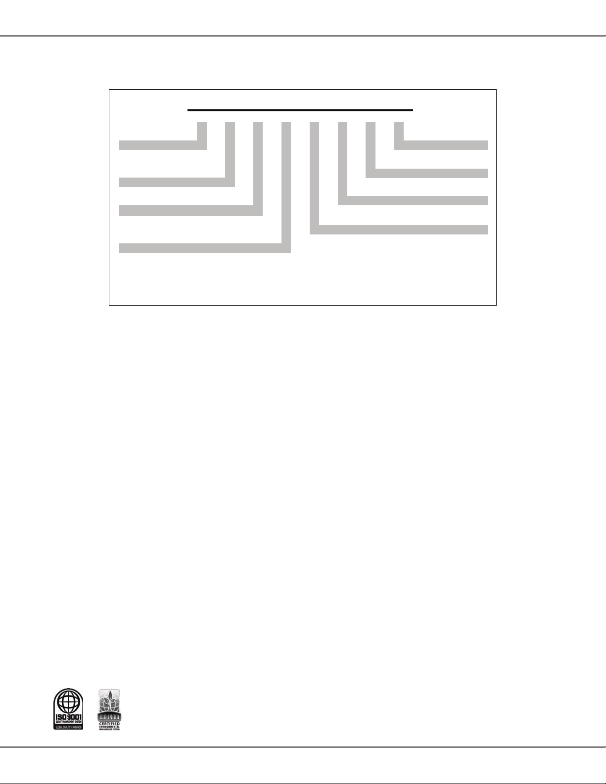
P
Brand Engineering *
G
Goodman® (Standard
Minor Revision
Feature Set Models)
Engineering *
Product Category Major Revision
S Split System
Electrical
Unit Type 1 208/230 V, 1 Phase, 60 Hz
C Condenser R-22
H Heat Pump R-22 Nominal Capacity
018 1½ Tons 042 3½ Tons
Efficiency 024 2 Tons 048 4 Tons
13 13 SEER 030 2½ Tons 060 5 Tons
036 3 Tons
* Neither used for order entry
or inventory management.
11
A
S
2
1
G
H3036
6,7,8134,5
9110
A
roduct SPecificationS
nomenclaTuRe
2 www.goodmanmfg.com SS-GSH13
Page 3
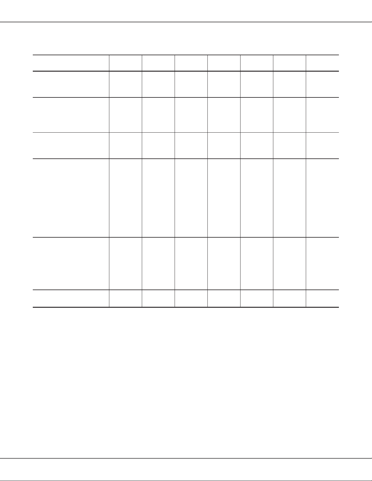
SpecificaTionS
P
roduct SPecificationS
GSH13
0181C*
Capacities and Ratings
Tonnage 1½ 2 2½ 3 3½ 4 5
Decibels 73 71 72 71 76 76 77
Compressor
RLA 8.3 10.8 13.5 14.1 19.2 19.9 25.0
LRA 40.3 56.0 68.0 75.0 112.0 104.0 148.0
Type Scroll Scroll Scroll Scroll Scroll Scroll Scroll
Condenser Fan Motor
Horsepower 1/8 1/8 1/8 ¼ ¼ ¼ 1/6
FLA 0.7 0.7 0.7 1.5 1.5 1.5 1.1
Refrigerant System
Refrigerant Line Size
Liquid Line Size (“O.D.) ⅜" ⅜" ⅜" ⅜" ⅜" ⅜" ⅜"
Sucon Line Size (“O.D.) ¾" ¾" ¾" ⅞" 1⅛" 1⅛" 1⅛"
Refrigerant Connecon Size
Liquid Valve Size (“O.D.) ⅜" ⅜" ⅜" ⅜" ⅜" ⅜" ⅜"
Sucon Valve Size (“O.D.) ¾" ¾" ¾" ⅞" ⅞" ⅞" ⅞"
Valve Type Sweat Sweat Sweat Sweat Sweat Sweat Sweat
Refrigerant Charge 127 122 130 188 246 208 233
Electrical Data
Voltage-Phase (60 Hz) 208/230-1 208/230-1 208/230-1 208/230-1 208/230-1 208/230-1 208/230-1
Minimum Circuit Ampacity ² 11.1 14.2 17.6 19.1 25.5 26.4 32.3
Max. Overcurrent Protecon ³ 15 25 30 30 40 45 50
Min / Max Volts 197/253 197/253 197/253 197/253 197/253 197/253 197/253
Electrical Conduit Size ½" or ¾" ½" or ¾" ½" or ¾" ½" or ¾" ½" or ¾" ½" or ¾" ½" or ¾"
Equipment Weight (lbs) 142 147 146 146 152 152 278
Ship Weight (lbs) 159 164 164 164 170 170 300
GSH13
0241C*
GSH13
0301C*
GSH13
0361C*
GSH13
0421B*
GSH13
0481B*
GSH13
0601A*
¹ Tested and rated in accordance with AHRI Standard 210/240
² Wire size should be determined in accordance with Naonal Electrical Codes; extensive wire runs will require larger wire sizes
³ Must use me-delay fuses or HACR-type circuit breakers of the same size as noted.
Notes
• Always check the S&R plate for electrical data on the unit being installed.
• Installer will need to supply ⅞” to 1⅛” adapters for sucon line connecons.
• Charge to be added for 15’ of ⅜” liquid line. System charge must be adjusted per Installaon Instrucons Final Charge Procedure.
• Installaon of these units requires the specied TXV Kit to be installed on the indoor coil. THE SPECIFIED TXV IS DETERMINED BY THE OUTDOOR UNIT NOT THE INDOOR COIL.
SS-GSH13 www.goodmanmfg.com 3
Page 4

P
roduct SPecificationS
aHRi RaTinGS
Outdoor
Unit
GSH130484A* AR*F486016B* 45,000 33,800 13.0 11.0 41,500 31,800 43,000 8.2 27,000 1,600 1492572
GSH130601A* AR*F486016B* 55,500 41,000 13.0 11.0 51,500 37,000 55,500 8.5 35,000 1,800 1492576
GSH130603A* AR*F486016B* 55,500 41,000 13.0 11.0 51,500 37,000 55,500 8.5 35,000 1,800 1492581
GSH130604A* AR*F486016B* 55,500 41,000 13.0 11.0 51,500 37,000 55,500 8.5 35,000 1,800 1492585
GSH130241(B,C)* AR*F182416B*+TXV 23,000 17,800 13.0 11.0 21,400 15,800 21,400 7.7 11,800 860 4675037
GSH130301(B,C)* AR*F363616B* 27,800 20,200 13.0 11.0 25,800 19,300 25,400 7.7 15,300 1,020 4692016
GSH130181(B,C)* AR*F182416B* 17,600 13,100 13.0 11.0 16,300 11,800 16,800 7.7 8,900 625 4675036
GSH130361(B,C)* AR*F374316B* 33,600 26,200 13.0 11.0 31,000 23,400 31,400 7.7 18,200 1,260 4692017
GSH130604AC AR*F486016B* 55,500 41,500 13.0 11.0 51,500 37,000 55,500 8.5 35,000 1,800 4982919
GSH130481B* AR*F486016B* 45,000 33,800 13.0 11.0 41,500 31,800 43,000 8.2 27,000 1,600 5528480
GSH130421B* AR*F364216B* 40,000 29,800 13.0 11.0 37,200 28,200 39,000 8.0 23,000 1,250 5528479
GSH130363A* AR*F374316B* 33,600 26,200 13.0 11.0 31,000 23,400 31,400 7.7 18,200 1,260 5528484
GSH130483B* AR*F486016B* 45,000 33,800 13.0 11.0 41,500 31,800 43,000 8.2 27,000 1,600 5528481
GSH130484AD AR*F486016B* 45,000 33,200 13.0 11.0 41,500 31,800 43,000 8.2 27,000 1,600 5528482
¹ BTU/h ² Seasonal Energy Eciency Rao; Cered per AHRI 210/240 @ 80°F/ 67°F/ 95°F
³ Energy Eciency Rao @ 80°F/ 67°F/ 95°F ⁴ TVA Rang: BTU/h @ 75°F/ 63°F - 95°F ⁵ HSPF = Heang Seasonal Performance Factor
Notes
• Always check the S&R plate for electrical data on the unit being installed.
• When matching outdoor unit to indoor unit, use the piston supplied with outdoor unit or that specied on the piston kit chart supplied with the indoor unit.
• EEP - Order from Service Dept. Part No. B13707-38 or new Solid State Board B13707-35S. Part No. B13707-38 is not interchangeable with B13707-35S. The Goodman Gas Furnace contains the EEP cooling me delay
Indoor
Unit
Cooling Capacity¹
SEER² EER³
Tota l Sens. Tota l Sens. High HSPF⁵ Low
TVA Ratings⁴ Heating Capacity¹
CFM AHRI #
4 www.goodmanmfg.com SS-GSH13
Page 5

DimenSionS
P
roduct SPecificationS
W
H
D
Dimensions
Model
W” D” H”
GSH130181C 26 26 32¼
GSH130241C 26 26 32¼
GSH130301C 29 29 34¾
GSH130361C 29 29 38¼
GSH130421B 29 29 32¼
GSH130481B 29 29 34¾
GSH130601A 35½ 35½ 34¾
SS-GSH13 www.goodmanmfg.com 5
Page 6

P
roduct SPecificationS
WiRinG DiaGRam
L2
C
T2
SC
1
2
SR
SEE RATING PLATE
OUTDOOR POWER SUPPLY
5
T1
C
L1
RCCF
HC
S
COMP
X
U
A
IO
C
C
SA
(IF USED)
F
R
N
I
A
M
POLE CONT ACTOR ONLY
ALTERNATE DOUBLE
N
I
X
A
U
A
M
CH
CM
IO
DF2
CHS
HVDR
DF1
NOTE 3
(IF USED)
C
Y
DC
DFT
DFT
R
C
RVC
LPS
Y
SUPPLY
W2
LVDR
W2
ORO
INDOOR POWER
O
R
USE N.E.C. CLASS 2 WIRE
NOTES:
1. TO INDOOR UNIT LOW VOLTAGE TERMINAL BLOCK & INDOOR
THERMOSTAT.
2. START ASSIST FACTORY EQUIPPED WHEN REQUIRED.
3. CRANKCASE HEATER & CRANKCASE HEATER SWITCH ARE
FACTORY INSTALLED OPTION.
4. USE COPPER CONDUCTOR ONLY.
0140R00019P-B
⚡
LVJB
CONTROL BOX
NOTE 1
W2
RCY
O
RD
WH
BLYLOR
COMPONENT CODE
C --------------- CONTACTOR
CH ------------- CRANKCASE HEATER
CHS ------------- CRANKCASE HEATER SWITCH
CM ------------ OUTDOOR FAN MOTOR
COMP -------- COMPRESSOR
DC ------------- DEFROST CONTROL
DFT ----------- DEFROST THERMOSTAT
HVDR -------- HIGH VOLTAGE DEFROST RELAY
IO -------------- INTERNAL OVERLOAD
LPS ------------ LOW PRESSURE SWITCH
LVDR --------- LOW VOLTAGE DEFROST RELAY
LVJB ---------- LOW VOLTAGE JUNCTION BOX
RCCF --------- RUN CAPACITOR FOR COMPRESSOR & FAN
RVC ----------- REVERSING VALVE COIL
SA ------------- START ASSIST
SC ------------- START CAPACITOR FOR COMPRESSOR (OPTIONAL)
SR ------------- START RELAY FOR COMPRESSOR (OPT IONAL)
OLOR CODE
BK --------------- BLACK
BL --------------- BLUE
BR --------------- BROWN
OR --------------- ORANGE
PU --------------- PURPLE
C
BK
BK
DF1
DF2
HVD
R
DFT
RR
DC
LVDR
W2
OO
YC
RD --------------- RED
RD
RD
RD
WH
BK
OR
YL
BL
WIRING CODE
WH -------------- WHITE
YL --------------- YELLOW
FACTORY WIRING
HIGH VOLTAGE
LOW VOLTAGE
OPTIONAL HIGH VOLTAGE
FIELD WIRING
HIGH VOLTAGE
BL
RD
SC
RD
C
RD
RD
L2
T2
BKBK
BK
T1
L1
BK
BL
BL
YL
SR
BK
5
RCCF
RD
PU
RD
BK
YL
YL
BL
1
YL
2
YL
FC
RD
SA
H
PU
NOTE 2
(IF USED)
RD
BR
YL
L2
T2
L1
T1
ALTERNATE
SEE NOTE 4
EQUIPMENT GROUND
BK
BK
RVC
BK
COMP
CONTACTOR
DOUBLE POLE
BK
RD
RD
BK
DFT
RD
RD
S
AUX
MAIN
C
BK
YL
RD
PU
AUX
MAIN
CONTROLS SHOWN WITH THERMOSTAT IN 'OFF' POSITION.
GR
High Voltage: Disconnect all power before servicing or installing this unit. Mulple power
sources may be present. Failure to do so may cause property damage, personal injury, or death.
CH
CHS
(IF USED)
SEE NOTE 3
YL
⚠ Warning
LPS
YL
R
Wiring is subject to change. Always
refer to the wiring diagram or the
BR
BK
CM
IO
unit for the most up-to-date wiring.
6 www.goodmanmfg.com SS-GSH13
Page 7

acceSSoRieS
P
roduct SPecificationS
Model Description
ABK-20 Anchor Bracket Kit
ASC01 An-Short Cycle Kit X X X X X X X
CSR-U-1 Hard-start Kit X X X X X X
CSR-U-2 Hard-start Kit
CSR-U-3 Hard-start Kit X
FSK01A¹ Freeze Protecon Kit X X X X X X X
OT/EHR18-60 Emergency Heat Relay kit X X X X X X X
OT18-60A² Outdoor Thermostat with Lockout Stat X X X X X X X
*
Contains 20 brackets; four brackets needed to anchor unit to pad
¹ Installed on indoor coil
² Required for heat pump applicaons where ambient temperatures fall below 0 °F with 50% or higher relave humidity.
³ Condensing units and heat pumps with reciprocang compressors require the use of start-assist components when used in conjuncon with an indoor
coil using a non-bleed thermal expansion valve refrigerant metering device. The TXV should always be sized based on the tonnage of the outdoor unit.
*
GSH13
018
GSH13
024
X X X X X X X
GSH13
030
GSH13
036
GSH13
042
GSH13
048
GSH13
060
SS-GSH13 www.goodmanmfg.com 7
Page 8

P
roduct SPecificationS
noTeS
Goodman Manufacturing Company, L.P., reserves the right to discontinue, or change at any time, specications or designs without
notice or without incurring obligations. © 2013 • Goodman Manufacturing Company, L.P. • Houston, Texas • Printed in the USA.
8 www.goodmanmfg.com SS-GSH13
 Loading...