

Page 1
®
TECHNICAL MANUTECHNICAL MANU
TECHNICAL MANU
TECHNICAL MANUTECHNICAL MANU
ALAL
AL
ALAL
GKS9
40" 90% Gas Furnaces
• Refer to Service Manual RS6610004* for installation, operation, and troubleshooting information.
• All safety information must be followed as provided in the Service Manual.
• Refer to the appropriate Parts Catalog for part number information.
• Model numbers listed on page 3.
This manual is to be used by qualified, professionally trained HVAC technicians only. Goodman
does not assume any responsibility for property damage or personal injury due to improper
service procedures or services performed by an unqualified person.
Copyright © 2006-2007, 2009 Goodman Manufacturing Company, L.P.
®
C
US
RT6612017r2
June 2009
Page 2
PRODUCT IDENTIFICATION
The model and manufacturing number are used for positive identification of component parts used in manufacturing. When
engineering and manufacturing changes take place where interchangeability of components are affected, the manufacturing number will change.
It is very important to use the model and manufacturing numbers at all times when requesting service or parts information.
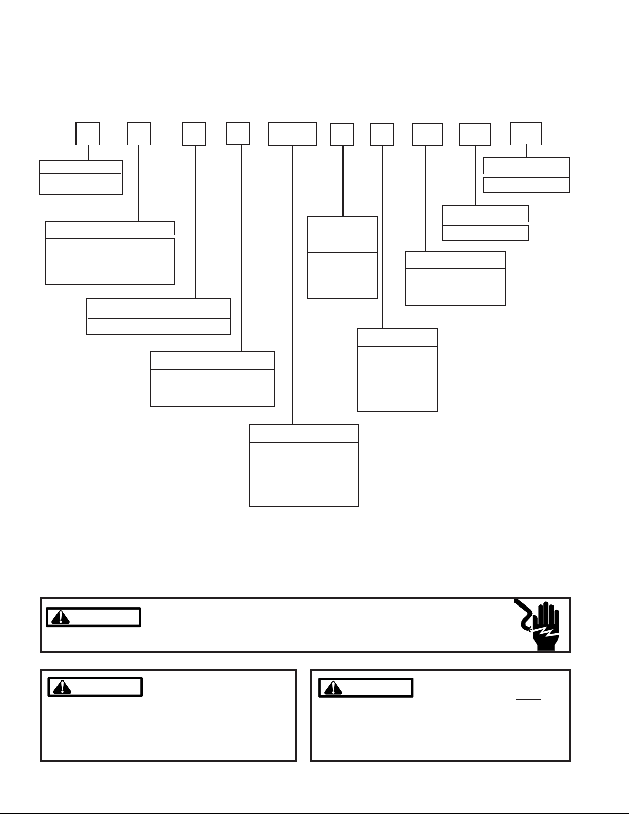
G K S 9 045 3 B X A
Product Type
G: Gas Furnace
Supply Type
C: Counterflow/Horizontal
M: Upflow/Horizontal
K: Residential Upflow
Furnace Type
S: Single Stage/Multi-Speed
Model Family
9: Air Command 90
(40" Height)
Nominal Input
Airflow
Capability
3: 1200
4: 1600
5: 2000
A
Minor Revision
A: Initial Release
Major Revision
A: Initial Release
Additional Features
N: Natural Gas
X : Low NOx
Cabinet Width
A: 14"
B: 17 1/2"
C: 21"
D: 24 1/2"
045: 45,000 Btuh
070: 70,000 Btuh
090: 90,000 Btuh
115: 115,000 Btuh
HIGH VOLTAGE!
WARNING
WARNING
WARNING
WARNING
arising from improper service or service procedures. If
you install or perform service on this unit, you assume
responsibility for any personal injury or property damage
which may result. Many jurisdictions require a license to
install or service heating and air conditioning equipment.
Disconnect ALL power before servicing or installing this unit. Multiple power
sources may be present. Failure to do so may cause property damage, personal
injury or death.
Goodman will not be responsible
for any injury or property damage
WARNING
WARNING
individuals meeting the requirements of an "entry level
technician" as specified by the Air-Conditioning, Heating,
and Refrigeration Institute (AHRI). Attempting to install or
repair this unit without such background may result in
product damage, personal injury or death.
Installation and repair of this unit
should be performed
ONLY by
2
Page 3
PRODUCT IDENTIFICATION
The model and manufacturing number are used for positive identification of component parts used in manufacturing. When
engineering and manufacturing changes take place where interchangeability of components are affected, the manufacturing number will change.
GKS90453BX*
GKS90703BX*
GKS90704CX*
GKS90904CX*
GKS90905DX*
GKS91155DX*
* Indicates minor revision & is not used for order entry or inventory management
WARNING
WARNING
WARNING
WARNING
Serious property damage, personal injury, reduced unit
performance and/or hazardous conditions may result
from the use of such non-approved devices.
The United States Environmental Protection Agency (“EPA”) has issued various regulations regarding the introduction and disposal of refrigerants introduced into this unit. Failure to follow
these regulations may harm the environment and can lead to the imposition of substantial fines.
These regulations may vary by jurisdiction. Should questions arise, contact your local EPA office.
Do not connect or use any device
that is not design certified by
Goodman for use with this unit.
WARNING
WARNING
do not store combustible materials or use gasoline or
other flammable liquids or vapors in the vicinity of this
appliance.
To prevent the risk of property
damage, personal injury, or death,
3
Page 4
PRODUCT DESIGN
General Operation
The GKS9 furnaces are equipped with an electronic ignition
device used to light the burners and an induced draft blower
to exhaust combustion products.
An interlock switch prevents furnace operation if the blower
door is not in place. Keep the blower access door in place
except for inspection and maintenance.
This furnace is also equipped with a self-diagnosing electronic control module. In the event a furnace component is
not operating properly, the control module LED will flash on
and off in a factory-programmed sequence, depending on
the problem encountered. This light can be viewed through
the observation window in the blower access door. Refer to
the Troubleshooting Chart for further explanation of the LED
codes and Abnormal Operation - Integrated Ignition Control
section in the Service Instructions for an explanation of the
possible problem.
The rated heating capacity of the furnace should be greater
than or equal to the total heat loss of the area to be heated.
The total heat loss should be calculated by an approved
method or in accordance with “ASHRAE Guide” or “Manual
J-Load Calculations” published by the Air Conditioning Contractors of America.
*Obtain from: American National Standards Institute 1430
Broadway New York, NY 10018
Location Considerations
• The furnace should be as centralized as is practical
with respect to the air distribution system.
• Do not install the furnace directly on carpeting, tile, or
combustible material other than wood flooring.
• When suspending the furnace from rafters or joists,
use 3/8" threaded rod and 2” x 2” x 3/8” angle as
shown in the Installation and Service Instructions. The
length of the rod will depend on the application and
clearance necessary.
• When installed in a residential garage, the furnace
must be positioned so the burners and ignition source
are located not less than 18 inches (457 mm) above
the floor and protected from physical damage by vehicles.
Notes:
1. Installer must supply one or two PVC pipes: one for combustion air (optional) and one for the flue outlet (required).
Vent pipe must be either 2” or 3” in diameter, depending
upon furnace input, number of elbows, length of run and
installation (1 or 2 pipes). The optional Combustion Air
Pipe is dependent on installation/code requirements and
must be 2” or 3” diameter PVC.
2. Line voltage wiring can enter through the right or left side
of the furnace. Low voltage wiring can enter through the
right or left side of furnace.
3. Conversion kits for high altitude natural or propane gas
operation are available. See High Altitude Derate chart
for details.
4. Installer must supply the following gas line fittings, depending on which entrance is used:
Left -- Two 90º Elbows, one close nipple, straight pipe.
Right -- Straight pipe to reach gas valve.
Accessibility Clearances (Minimum)
MINIMUM CLEARANCES TO COMBUSTIBLE MATERIALS
(INCHES)
POSITION* FRONT SIDES REAR TOP FLUE FLOOR
Upflow - 0 0 1 0 C
Counterflow 1 0 0 1 0 NC
Horizontal 1 6 0 4 0 C
*= All positioning is determined as installed unit is viewed from the front.
C= If placed on combustible floor, floor MUST be wood only.
NC= For instalaltion on non-combustible floors only. A combustible
subbase must be used for installations on combustible flooring.
36" at front is required for servicing or cleaning.
Note: In all cases accessibility clearance shall take prece-
dence over clearances from the enclosure where accessibility clearances are greater. All dimensions are given in inches.
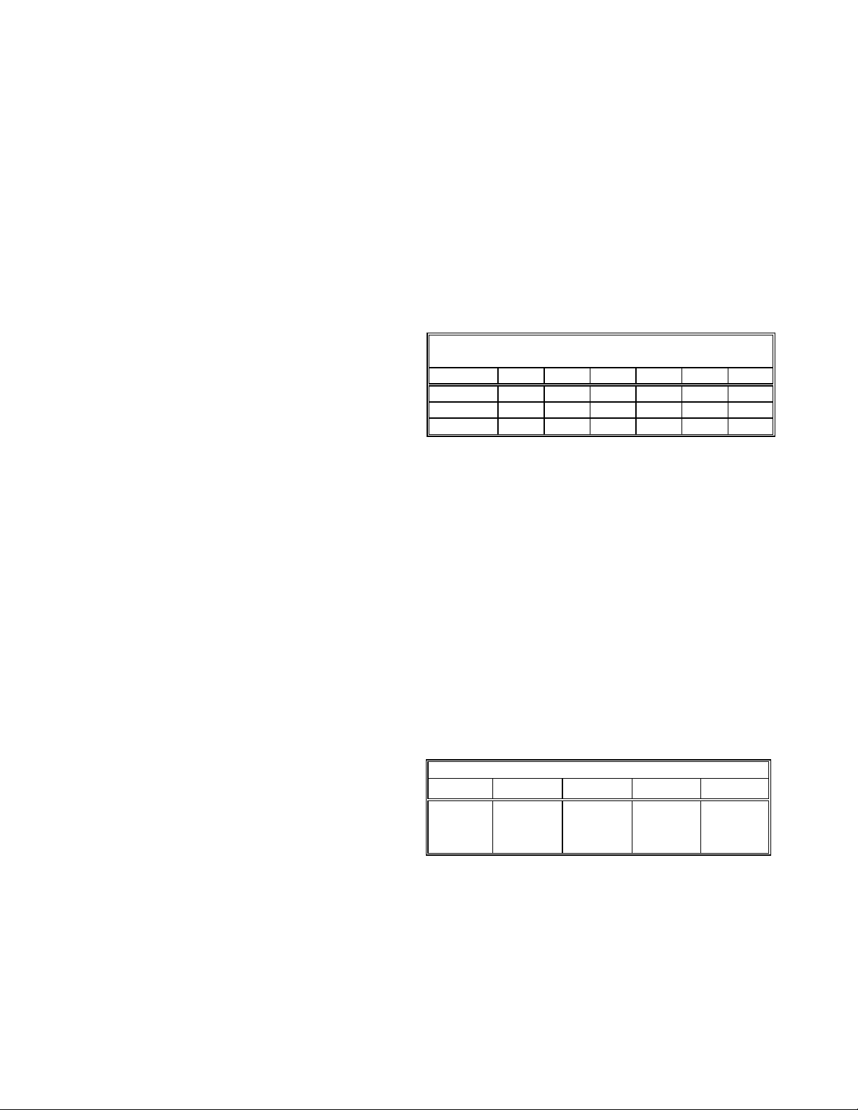
High Altitude Derate
When this furnace is installed at high altitude, the appropriate High Altitude orifice kit must be installed. This is required due to the natural reduction in the density of both the
gas fuel and combustion air as altitude increases. The kit
will provide the proper design certified input rate within the
specified altitude range.
PROPANE AND HIGH ALTITUDE KITS
0 - 7,000 ft. 7,001-9,000 ft. 9,001-11,000 ft. 7,001-11,000 ft. 7,001-11,000 ft.
LPT-00A
Propane
Conversion Kit
(#55 Orifices)
TBD TBD TBD TBD
High altitude kits are purchased according to the installation altitude and usage of either natural or propane gas. Refer
to the chart above for a tabular listing of appropriate altitude
ranges and corresponding manufacturer’s high altitude Natural Gas and Propane Gas kits. For a tabular listing of appropriate altitude ranges and corresponding manufacturer's High
Altitude Pressure Switch kits, refer to either the Pressure
Switch Trip Points & Usage Chart in this manual or the Accessory Charts in Service Instructions.
4
Page 5
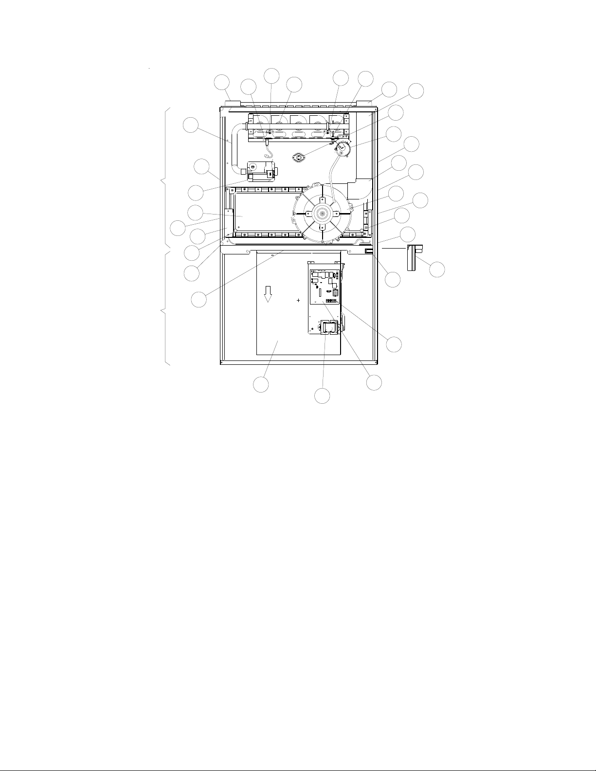
COMPONENT IDENTIFICATION
29
25
17
18
27
26
3
2
1
24
6
4
5
6
7
8
9
10
11
12
13
14
15
16
17
18
28
19
20
BLOWER COMPARTMENT BURNER COMPARTMENT
23
Upflow/Horizontal
1 Gas Valve
2 Gas Line Entrance (Alternate)
3 Combustion Air Intake Connection / “Coupling”
4 Hot Surface Igniter
5 Burners
6 Rollout Limit
7 Flame Sensor
8 Flue Pipe Connection / “Coupling”
9 Flue Pipe (Internal)
1 0 Primary Limit
11 Pressure Switch
12 Gas Line Entrance
13 Rubber Elbow
14 Flue Pipe Connection (Alternate)
15 Induced Draft Blower
21
22
16 Electrical Connection Inlets (Alternate)
17 Coil Front Cover Drain Port
18 Drain Line Penetrations
19 Blower Door Interlock Switch
20 24-Volt Thermostat Connections
21 Integrated Control Module
(with fuse and diagnostic LED)
22 Transformer (40 VA)
23 Circulator Blower
2 4 Auxiliary Limit
25 Gas Manifold
26 Junction Box
27 Coil Front Cover
28 Drain Trap
29 Electrical Connection Inlets
5
Page 6

COMPONENT IDENTIFICATION
A
A
1 5/8
1 1/2
1
AIR
DISCHARGE
20 13/16
HIGH VOLTAGE
ELECTRICAL HOLE
LEFT SIDE
DRAIN LINE HOLES
LOW VOLTAGE
ELECTRICAL HOLE
SIDE CUT-OUT
22 1/16
UNFOLDED FLANGES
23 9/16
FOLDED FLANGES
AIR
INTAKE
PIPE
2" PVC
GKS9
(DISCHARGE)
UNFOLDED FLANGES
FOLDED FLANGES
IR
DISCHARGE
B
C
STANDARD GAS
CONDENSATE
DRAIN TRAP
w/ 3/4" PVC
DISCHARGE
(RIGHT OR
LEFT SIDE)
2
SUPPLY HOLE
HIGH VOLTAGE
ELECTRICAL HOLE
DRAIN
TRAP
LOW VOLTAGE
ELECTRICAL HOLE
SIDE CUT-OUT
RIGHT SIDE
DRAIN LINE
HOLES
LEFT SIDE VIEW
Cabinet Size A B C D E
GKS90453BX*
GKS90703BX*
GKS90704CX*
GKS90904CX*
GKS90905DX*
GKS91155DX*
17-1/2
21
24-1/2
FRONT VIEW
16
19-1/2
23
12-15/16
15-15/16
20-7/16
12-1/8
19-3/8
All dimensions are in inches.
16
RIGHT SIDE VIEW
13-5/8
17-1/2
20-7/8
NOTE: Airflow area will be reduced by approximately 18% if duct flanges are not unfolded. This could cause
performance issues and noise issues.
6
Page 7

PRODUCT DESIGN
PRESSURE SWITCH TRIP POINTS AND USAGE CHART
MODEL
NEGATIVE PRESSURE
ID BLOWER
WITH FLUE NOT FIRING
TYPICAL SEA
LEVEL DATA
NEGATIVE PRESSURE
ID BLOWER
WITH FLUE FIRING
TYPICAL SEA
LEVEL DATA
NEGATIVE PRESSURE
COIL COVER
WITH FLUE NOT FIRING
TYPICAL SEA
LEVEL DATA
NEGATIVE PRESSURE
COIL COVER
WITH FLUE FIRING
TYPICAL SEA
LEVEL DATA
GKS90453BX* -1.40 -1.20 -0.52 -0.37
GKS90703BX* -1.30 -1.10 -0.52 -0.37
GKS90704CX* -1.30 -1.10 -0.52 -0.37
GKS90904CX*
-1.10 -0.95 -0.52 -0.37
GKS90905DX* -0.90 -0.75 -0.52 -0.37
GKS91155DX* -1.30 -1.10 -0.52 -0.37
(1) Data given for the flue not firing is least negative pressure required for switch to close.
(2) Data given for the flue firing is least negative pressure required for the switch to remain closed.
PRESSURE SWI TCH TRIP POINTS AND USAGE
0 to 7,000 ft. 7,001 to 11,000 ft.
ID BLOWER
PRESSURE
MODEL
GKS90453BX*
GKS90703BX*
GKS90704CX*
GKS90904CX*
GKS90905DX*
GKS91155DX*
TRIP POINT
COIL COVER
PRESSURE
SWITCH
-0.37 20197312 -1.20 0130F00001P TBD TBD TBD
-0.37 20197312 -1.10 0130F00000P TBD TBD TBD
-0.37 20197312 -1.10 0130F00000P TBD TBD TBD
-0.37 20197312 -0.95 0130F00002P TBD TBD TBD
-0.37 20197312 -0.75 0130F00004 TBD TBD TBD
-0.37 20197312 -1.10 0130F00001P TBD TBD TBD
COIL COVER
PRESSURE
SWITCH
PART #*
TRIP POINT
ID BLOWER
PRESSURE
SWITCH
Note: For installations in Canada, this 90% furnace is certified only to 4500.ft.
Note: All negative pressure readings are in inches of water column (" w.c.).
SWITCH
PART #*
TRIP POINT
COIL COVER
PRESSURE
SWITCH
TRIP POINT
ID BLOWER
PRESSURE
SWITCH
HIGH
ALTITUDE
KIT
* GKS9 furnaces are shipped without coil cover pressure switches. All GKS9 models are shipped from the factory as Dedicated Upflow but can
be installed as a Horizontal Left or a Horizontal Right, ONLY after installing GKS9 Horizontal Installation Kit 0270K00012, which contains
Pressure Switch 20197312.
7
Page 8

PRODUCT DESIGN
Part Number 20162903 20162904 20162906
T.O.D. PRIMARY LIMIT
Open Setting (°F)
GKS90453BX*
GKS90703BX*
GKS90704CX*
GKS90904CX*
GKS90905DX*
GKS91155DX*
Open Setting (°F)
160 150 170
1
1
1
1
1
ROLLOUT LIMIT SWITCHES
10123514
Part Number
10123533
GKS90453BX*
1
or
200
1
GKS90703BX*
GKS90704CX*
GKS90904CX*
GKS90905DX*
GKS91155DX*
AUXILIARY LIMIT SWITCHES
Part Number 10123519 10123535
Open Setting (°F)
GKS90453BX*
GKS90703BX*
GKS90704CX*
GKS90904CX*
GKS90905DX*
160 150
2
2
2
2
2
1
1
1
1
1
GKS91155DX*
8
1
Page 9

PRODUCT DESIGN
r
Coil Matches:
A large array of Amana® brand coils are available for use with the GKS9 furnaces, in either upflow, counterflow, or
horizontal applications. These coils are available in both cased and uncased models (with the option of a field installed TXV
expansion device). These 90%+ furnaces match up with the existing Amana® brand coils as shown in the chart below.
Coil Matches (for Goodman
C A P F 1824 A 6 A
EXPANSION
PRODUCT
TYPE:
C: Indoor Co il
APPLICATION
A: Up fl ow/D ownfl ow Coil
H: Horizontal A Coil
S: Horizo ntal Slab Coil
CAB INE T FINIS H:
U: Unpainted
P: Painted
N: Unpai nted Ca s e
DEVICE:
F: Flowrate
®
units using R22 and R-410A):
REFRIGERANT
CHARGE:
6 : R- 41 0A or R-22
2: R - 22
4: R - 410a
NOMINAL WI DT H FO R GAS F URNACE
A: Fits 14" Fur nac e Cabinet
B: Fits 17 1/2" Furnace Cabinet
C: Fits 21" Furnace Cabinet
D: Fits 24 1/2" Furnace Cabinet
N: Does Not A pply (Hor izontal S lab Coi ls)
REVISION
A : Revision
NOMINA L CAPACITY RANGE
@ 13 SEER
1824: 1 1/2 to 2 Ton s
3030: 2 1/2 Tons
3636: 3 Tons
3642: 3 to 3 1/2 Ton s
3743: 3 to 3 1/2 Ton s
4860: 4 & 5 Tons
4961: 4 & 5 Tons
• All CAPF coils in B, C, & D widths have insulated blank off plates for use with one size smaller furnaces.
• All CAPF coils have a CAUF equivalent.
• All CHPF coils in B, C & D heights have an insulated Z bracket for use with one size smaller furnace.
• All proper coil combinations are subject to being ARI rated with a matched outdoor unit.
9
Page 10

PRODUCT DESIGN
Thermostats:
NOTE: Complete lineup of thermostats can be found in the Thermostat Specification Sheets.
Filters:
Filters are required with this furnace and must be provided by the installer. The filters used must comply with UL900 or
CAN/ULCS111 standards. Installing this furnace without filters will void the unit warranty.
Upflow Filters
This furnace has provisions for the installation of return air filters at the side and/or bottom return. The furnace will
accommodate the following filter sizes depending on cabinet size:
BOTTOM RETURNSIDE RETURN
Cabinet
Width
(in.)
Nominal
Filter Size
(in.)
Approx.
Flow Area
2
)
(in
Cabinet
Width
(in.)
Nominal
Filter Size
(in.)
All 16 x 25 x 1 400 17-1/2 14 x 25 x 1 350
21 16 x 2 5 x 1 400
24-1/ 2 20 x 25 x 1 500
Approx.
Flow Area
2
)
(in
Refer to Minimum Filter Area tables to determine filter area requirement. NOTE: Filters can also be installed elsewhere in
the duct system such as a central return.
COOLING AIRFLOW REQUIREMENT (CFM)
600 800 1000 1200 1400 1600 2000
0453_X* 376* 384 480 576 --- --- --0703_X* --- 564* 564* 564* 672 --- --0704_X* --- --- 564* 564* 672 768 --0904_X* --- --- 752 * 752* 752* 768 ---
Input__Airflow
0905_X* --- --- --- 752* 752* 768 800
1155_X* --- --- --- 940* 940* 940* 800
*Minimum filter area dictated by heating airflow requirement.
Disposable Minimum Filter Area (in2)
[Based on a 300 ft/min filter face velocity]
0453_X* 188* 192 240 288 --- --- --0703_X* --- 282* 282* 282* 336 --- --0704_X* --- --- 260* 260* 336 384 --0904_X* --- --- 376* 376* 376* 384 ---
Input__Airflow
0905_X* --- --- --- 376* 376* 384 480
115_X* --- --- --- 470* 470* 470* 480
*Minimum filter area dictated by heating airflow requirement.
Permanent Minimum Filter Area (in2)
[Based on 600 ft/min filter face velocity]
COOLING AIRFLOW REQUIREMENT (CFM)
600 800 1000 1200 1400 1600 2000
10
Page 11

FURNACE SPECIFICATIONS
MODEL
GKS9
0453BX*
GKS9
0703BX*
GKS9
0704CX*
GKS9
0904CX*
GKS9
0905DX*
GKS9
1155DX*
Btuh
Input (US) 46,000 69,000 69,000 92,000 92,000 115,000
Output (US) 42,800 64,400 63,900 86,000 86,000 106,500
Input (CAN) 46,000 69,000 69,000 92,000 92,000 115,000
Output (CAN) 42,800 64,400 63,900 86,000 85,300 106,500
A.F.U.E. 92.1% 92.1% 92.1% 92.1% 92.1% 92.1%
Rated External Static (" w.c.) .20 - .50 .20 - .50 .20 - .50 .20 - .50 .20 - .50 .20 - .50
Temperature Rise (°F) 35 - 65 35 - 65 35 - 65 35 - 65 35 - 65 35 - 65
ID Blower Pressure Switch Trip Point (" w.c.) -1.20 -1.10 -1.10 -0.95 -0.75 -1.10
Blower Wheel (D" x W") 10 x 8 10 x 8 10 x 10 10 x 10 11 x 10 11 x 10
Blower Horsepower 1/3 1/3 1/2 1/2 3/4 3/4
Blower Speeds 4 4 4 4 4 4
Max CFM @ 0.5 E.S.P. 1200 1200 1600 1600 2000 2000
Power Supply 115-60-1 115-60-1 115-60-1 115-60-1 115-60-1 115-60-1
Minimum Circuit Ampacity (MCA)
Maximum Overcurrent Device
(2)
(1)
9.4 9.4 13.8 13.8 13.2 13.2
15.0 15.0 15.0 15.0 15.0 15.0
Transformer (VA) 40 40 40 40 40 40
Primary Limit Setting (°F) 150 160 160 150 160 170
Auxiliary Limit Setting (°F) 150 150 150 150 150 160
Rollout Limit Setting (°F) 200 200 200 200 200 200
Fan Delay On Heating 30 secs. 30 secs. 30 secs. 30 secs. 30 secs. 30 secs.
Off Heating 150 secs. 150 secs. 150 secs. 150 secs. 150 secs. 150 secs.
Fan Delay On Cooling 6 sec. 6 sec. 6 sec. 6 sec. 6 sec. 6 sec.
Off Cooling 45 secs. 45 secs. 45 secs. 45 secs. 45 secs. 45 secs.
Gas Supply Pressure (Natural/Propane) ("w.c.) 7 / 11 7 / 11 7 / 11 7 / 11 7 / 11 7 / 11
Manifold Pressure (Natural/Propane) ("w.c.) 3.5 / 10 3.5 / 10 3.5 / 10 3.5 / 10 3.5 / 10 3.5 / 10
Orifice Size (Natural/Propane) 43 / 55 43 / 55 43 / 55 43 / 55 43 / 55 43 / 55
Number of Burners 2 3 3 4 4 5
Vent Connector Diameter (inches)
(3)
Combustion Air Connector Diameter (inches)
(4)
222222
222222
Shipping Weight (lbs.) 132 135 153 158 170 175
(1)
Wire size should be determined in accordance with National Electrical Codes. Extensive wire runs will require larger wire sizes.
(2)
Maximum Overcurrent Protection Device: MUST use Time Delay Fuse or HACR type Circuit Breaker of the same size as noted.
(3)
See Installation Instructions for appropriate vent diameter, length and number of elbows.
(4)
See Installation Instructions for appropriate combustion air pipe diameter, length and number of elbows.
NOTE: This data is provided as a guide, it is important to electrically connect the unit and properly size fuses/circuit breakers and wires in
accordance with all national and/or local electrical codes. Use copper wire only.
1. These furnaces are manufactured for natural gas operation. Optional kits are available for conversion to propane operation.
2. For elevations above 2000 feet the rating should be reduced by 4% for each 1000 feet above sea level. The furnace must not be derated, orifice changes should
only be made if necessary for altitude.
3. The total heat loss from the structure as expressed in TOTAL BTU/HR must be calculated by the manufacturers method or in accordance with the "A.S.H.R.A.E.
GUIDE" or "MANUAL J-LOAD CALCULATIONS" published by the AIR CONDITIONING CONTRACTORS OF AMERICA. The total heat loss calculated should be
equal to or less than the heating capacity. Output based on D.O.E. test procedures, steady state efficiency times output.
4. Minimum Circuit Ampacity calculated as: (1.25 x Circulator Blower Amps) + I.D. Blower Amps.
Unit specifications are subject to change without notice.
ALWAYS refer to the units serial plate for the most up-to-date general and electrical information.
11
Page 12

BLOWER PERFORMANCE SPECIFICATIONS
BLOWER PER F ORMANCE
(CFM & Temperature Rise vs. External Static Pressure)
Model
Motor
Heating Speed
()
As Shipped
GKS90453BX* MED 2.5 1214 --- 1172 --- 1123 --- 1064 --- 1012 --- 938 859 741
(LOW) MED-LO 2.0 997 --- 994 --- 960 35 923 36 884 38 817 741 611
GKS90703BX* MED 2.5 119243117244114145109447104649 973904793
(MED-HI) MED-LO 2.0 981 53 962 54 943 55 917 56 888 58 830 764 665
GKS90704CX* MED 3.5 1752 --- 1724 --- 1667 --- 1603 --- 1488 35 1402 1290 1082
Speed
HIGH 3.0 1352 --- 1318 --- 1260 --- 1202 --- 1128 --- 1044 955 853
LOW 1.5 757 44 753 44 734 45 704 47 674 49 620 524 438
HIGH 3.0 144936140937132639127341120143119411361018
LOW 1.5 750 --- 730 --- 714 --- 692 --- 657 --- 620 570 502
HIGH 4.0 2069 --- 1965 --- 1871 --- 1756 --- 1661 --- 1549 1415 1275
Tons AC
at 0.5" 0.6 0.7 0.8
0.1 0.2 0.3 0.4 0.5
ESP CFM RISE CFM RISE CFM RISE CFM RISE CFM RISE CFM CFM CFM
EXTERNAL STATIC PRESSURE (Inches Water Column)
(LOW) MED-LO 3.0 14373614373614173613693813203912561140984
LOW 2.5 1184 44 1177 44 1161 44 1132 46 1095 47 1047 928 837
HIGH 4.0 1970---187435175738166740156642143113341182
GKS90904CX* MED 3.5 1713 39 1650 40 1572 42 1510 44 1418 47 1313 1211 1079
(MED-LO) MED-LO 3.0 14394614124713704813275012605311661078956
LOW 2.5 1183 56 1155 57 1122 59 1108 60 1062 62 1011 931 816
HIGH 5.0 2147 --- 2114 --- 2057 --- 2030 --- 1978 --- 1889 1784 1713
GKS90905DX* MED 4.0 1675 40 1686 --- 1640 40 1623 41 1557 43 1501 1455 1360
(MED-LO) MED-LO 3.5 148945147045143646140947136149131812431130
LOW 3.0 13075112655212345412035511685710961053991
HIGH 5.0 213440210340202942194144190644181817331625
GKS91155DX* MED 4.0 1678 51 1643 52 1643 52 1577 54 1527 56 1489 1423 1339
(MED-HI) MED-LO 3.5 145358144059142659136362134963131412531205
LOW 3.0 1259 67 1239 68 1220 70 1181 --- 1159 --- 1118 1082 1015
1. CFM in chart is without filters(s). Filters do not ship with this furnace, but must be provided by the installer. If the furnace requires two
return filters, this chart assumes both filters are installed.
2. All furnaces ship as high speed cooling. Installer must adjust blower cooling speed as needed.
3. For most jobs, about 400 CFM per ton when cooling is desirable.
4. INSTALLATION IS TO BE ADJUSTED TO OBTAIN TEMPERATURE RISE WITHIN THE RANGE SPECIFIED ON THE RATING PLATE.
5. The chart is for information only. For satisfactory operation, external static pressure must not exceed value shown on rating plate. The
shaded area indicates ranges in excess of maximum external static pressure allowed when heating. The data for 0.6" w.c. to 0.8" w.c.
is shown for air conditioning purposes only.
6 The dashed (---) areas indicate a temperature rise not recommended for this model.
7. The above chart is for U.S. furnaces installed at 0-4000 feet. At higher altitudes, a properly derated unit will have approximately the
same temperature rise at a particular CFM, while the ESP at that CFM will be lower.
12
Page 13

BLOWER PERFORMANCE SPECIFICATIONS
÷ CFM
130 140 150
FORMULAS
BTU OUTPUT = CFM x 1.08 x RISE
1.08
BTU OUTPUT
RISE =
100
2400 CFM
2200
2000
1800
1600
1400
1200
1100
1000
900
800
OUTPUT BTU/HR x 1000
BTU OUTPUT vs TEMPERATURE RI SE CHAR T
600 CFM
700
30 40 50 60 70 80 90 110 120
100
90
80
70
60
50
40
30
20
10
TEMPERATURE RISE
13
Page 14

WIRING DIAGRAMS
2
V
4
C
A
U
D
H
I
I
M
F
I
R
E
4
2
V
A
1
1
5
A
2
V
4
H
M
T
R
O
T
S
E
O
C
N
N
C
E
O
I
T
N
C
D
A
I
L
E
1
1
C
G
D
N
B
R
R
B
A
C
R
E
W
B
O
L
O
C
R
O
R
U
C
E
N
B
R
D
R
O
H
W
I
D
B
E
R
P
I
W
HIGH VOLTAGE!
DISCONNECT ALL POWER BEFORE SERVICING OR INST ALLING THIS
UNIT. MULTIPLE POWER SOURCES MAY BE PRESENT. FAILURE TO
DO SO MAY CAUSE PROPERTY DAMAGE, PERSONAL INJURY OR DEAT H.
S
I
R
2 C
O
C
N
N
O
H
T
F
R
U
S
I
G
T
I
N
0
D
A
Y
E
T
S
O
F
F
L
S
F
A
1
H
1
S
F
A
L
2
H
2
=
S
L
F
A
3
H
3
=
4
L
S
F
A
4
H
S
F
A
L
5
5
S
F
L
A
6
H
6
C
C
N
O
N
I
T
=
=
C
O
L
C
R
O
O
O
L
L
Y
L
E
Y
N
O
R
O
R
A
U
L
P
R
P
U
P
G
R
G
N
E
N
E
C
L
A
K
B
K
B
40F
0
1
A
T
S
G
D
5
V
O
O
P
A
M
M
G
N
O
L
O
S
S
T
C
U
C
E
A
R
E
O
E
E
E
H
E
E
U
D
E
W
G
E
E
002
V
R
G
W
Y
U
F
E
S
T
E
G
E
T
A
R
I
N
N
T
O
C
R
L
O
L
E
U
D
M
O
N
T
S
O
C
I
K
T
R
A
O
C
D
H
A
N
A
P
L
H
-
T
-
H
A
H
E
E
S
E
T
O
N
H
W
I
)
H
B
(
K
M
B
(
L
E
R
M
O
(
E
L
D
R
(
O
R
O
T
I
C
T
M
N
T
R
E
A
P
T
N
E
M
T
A
R
P
D
N
K
B
H
W
U
D
I
N
B
O
L
C
E
R
W
V
A
2
4
R
U
E
U
D
H
I
M
I
H
I
T
R
O
T
C
M
E
C
G
S
A
V
N
N
R
O
M
C
O
N
R
T
=
S
S
R
E
= P
S
S
S
R
E
= P
S
S
O
H
P
N
E
E
M
S
L
F
A
=
S
R
O
/
U
S
I
D
P
A
P
K
:
S
R
B
H
W
B
L
Y
G
R
D
E
6
R
3
O
C
C
K
B
D
G
XFMR-H
A
L
N
S
I
T
M
E
R
H
-
L
I
E
N
E
4
)
D
D
L
O
)
W
)
W
D
E
C
T
F
A
R
D
R
E
W
Y
L
C
I
F
R
E
C
2
R
B
G
I
A
V
L
E
O
L
P
R
A
E
A
T
L
U
I
R
A
F
O
L
I
W
U
C
T
S
R
E
C
T
I
W
U
S
R
E
I
M
H
T
G
L
I
I
E
N
S
T
I
E
S
W
= R
S
S
F
A
L
H
E
N
K
I
P
R
B
N
W
O
H
E
T
W
I
U
L
B
E
G
Y
R
A
R
E
D
D
V
.
GKS9*****X**
B
O
L
E
W
R
G
Y
H
W
R
O
1
3
2
5
6
Y
8
9
1
2
1
R
2
1
K
P
4
O
R
7
L
B
1
0
1
L
Y
R
O
Y
G
D
115 VAC NEUTRAL
TERMINAL S
W
H
H
W
K
B
B
L
R
G
B
R
PK
P
K
D
R
M
R
N
A
E
A
U
T
E
L
K
B
O
R
K
P
S
I
I
L
X
L
M
U
I
A
A
I
Y
R
P
U
W
I
O
F
L
N
W
K
O
C
E
L
E
R
D
B
U
P
H
W
W
H
U
P
L
B
YL
WH
WH
BL
T
OR
D
R
D
G
N
C
N
O
Y
O
N
I
E
S
C
H
U
T
L
O
C
S
D
K
H
S
T
H
U
O
E
V
O
N
S
.
1
M
.
2
I
.
3
H
I
.
4
B
U
.
5
E
O
P
N
E
U
C
K
A
T
G
V
L
A
V
S
E
R
S
E
E
T
:
S
T
E
H
N
A
U
A
F
Y
N
V
A
N
I
H
F
A
E
O
L
W
I
N
M
T
C
A
1
V
1
E
5
D
E
T
A
N
A
C
I
T
P
I
T
A
F
C
A
U
T
E
R
S
'
R
S
F
O
H
T
O
E
I
R
G
G
A
E
T
P
A
M
R
E
T
N
I
A
T
D
G
N
O
C
O
A
E
S
U
D
M
S
E
R
L
S
U
B
P
T
E
R
E
M
G
R
L
A
N
I
O
O
R
T
P
O
E
P
R
P
O
O
R
O
P
C
E
I
N
I
L
A
U
E
R
L
G
N
I
T
E
B
A
E
N
N
N
F
R
U
E
S
S
I
S
T
W
L
A
T
R
Y
I
N
O
R
M
H
O
T
R
E
M
E
I
R
F
D
P
E
A
L
E
C
M
I
W
E
R
S
A
U
S
P
P
L
A
R
N
I
T
G
F
O
T
A
L
B
O
L
E
S
W
R
E
P
E
L
P
C
A
D
E
N
O
P
"
A
L
T
G
Y
O
R
N
U
E
D
R
C
M
O
A
P
T
R
E
M
T
N
D
O
S
O
R
W
C
T
I
H
O
(
E
P
N
H
W
N
E
D
O
O
R
P
)
O
N
E
BK
GR
RD
C
24V THERMOSTAT CONNECTIONS
BK
G
T
O
Y
M
R
C
I
O
W
R
3
T
(
)
H
X
M
H
F
-
R
INTEGR ATED CONTROL M ODULE
GY
OR
BR
L
E
N
I
H
-
D
O
O
R
S
W
C
T
I
H
O
T
1
1
E
O
V
U
N
J
C
I
T
O
L
B
E
R
V
O
T
C
L
M
F
E
H
C
O
S
E
T
N
E
I
D
E
S
A
D
S
R
K
A
D
N
A
S
N
S
E
L
W
O
O
L
W
V
H
I
V
V
H
I
R
G
N
E
T
I
L
U
P
T
T
A
T
A
7
.
0
M
A
S
P
.
R
A
S
P
T
M
T
S
U
B
E
U
F
N
R
C
W
T
A
R
"
T
D
A
H
T
I
T
E
H
°
U
.
E
C
S
O
C
P
0
1
5
E
O
N
T
T
E
H
A
S
M
R
E
I
L
M
A
N
S
F
O
N
I
C
N
R
O
O
F
M
O
T
N
N
O
X
B
H
W
B
K
R
O
V
O
L
A
T
G
(
2
V
4
E
L
D
E
G
A
E
L
O
T
I
F
(
E
G
O
1
)
1
5
L
A
V
T
G
E
D
A
L
L
O
E
T
F
I
J
U
N
N
O
C
I
T
I
E
T
A
C
G
E
D
U
S
E
M
U
P
R
E
E
D
,
I
T
G
E
R
E
.
C
.
.
N
R
A
I
E
M
T
N
E
O
T
T
R
N
L
A
D
C
N
R
O
T
O
L
O
N
N
E
O
C
N
I
T
W
E
H
S
N
R
E
C
I
V
S
B
R
T
E
P
C
E
A
L
O
C
D
N
C
U
O
T
S
R
C
S
R
A
J
D
M
R
U
E
P
A
D
E
T
C
N
O
O
R
T
N
A
D
C
O
L
L
A
O
C
M
U
D
H
I
E
I
F
I
R
T
6
(
)
G
D
)
N
8
(
V
M
C
)
9
(
N
O
M
1
(
V
)
2
P
O
O
I
T
A
N
L
F
O
R
T
N
R
P
S
E
U
S
E
R
W
C
S
T
I
1
(
S
)
P
0
)
4
P
(
O
S
H
I
L
7
(
)
L
H
O
)
1
(
1
O
1
R
(
2
)
)
O
5
R
(
1
4
2
1
1
F
A
L
E
M
F
S
O
H
S
T
R
U
N
G
E
I
T
G
I
N
D
N
I
5
V
A
R
C
I
D
I
L
B
R
W
C
O
O
L
R
I
C
U
C
W
L
B
H
-
T
A
E
H
U
T
J
C
N
G
L
Ø
6
0
/
H
Z
1
C
/
R
P
U
R
N
R
E
T
)
L
N
I
.
G
D
E
T
I
U
,
M
T
S
E
B
R
L
P
N
O
B
E
O
L
E
D
S
E
Y
L
.
O
F
E
R
C
N
N
C
O
E
N
I
R
T
A
D
T
E
P
.
.
I
E
T
R
N
G
T
A
D
R
G
D
N
C
O
C
E
V
R
H
C
E
C
N
O
R
T
L
O
O
M
U
D
E
L
C
2
A
G
S
V
L
A
E
V
M
1
I
B
D
O
L
E
W
R
P
E
R
S
S
R
U
E
W
C
S
T
I
H
N
O
V
C
A
A
V
0
4
R
T
N
O
A
F
M
S
R
R
E
5
V
C
A
E
S
S
N
R
O
A
F
E
C
R
INTE GR ATED CONTROL MODULE
LINE NEUTRALS
A
R
L
O
T
R
B
X
O
O
I
N
S
I
D
O
C
N
N
C
E
T
D
N
N
P
S
U
R
P
W
E
O
N
O
I
E
T
T
O
C
H
P
L
T
I
W
Y
I
D
C
V
E
E
N
D
N
G
L
N
G
D
P
Q
U
E
I
T
E
M
N
F
N
I
G
E
D
L
D
C
S
L
E
I
P
E
L
I
F
D
)
.
P
M
E
T
C
T
H
(
S
I
W
R
E
G
T
N
I
I
C
S
T
H
I
W
E
V
O
R
P
)
(
.
P
S
R
S
E
R
C
U
R
D
O
.
T
N
R
E
T
C
E
E
I
V
C
A
D
I
E
W
H
I
T
W
N
I
M
R
T
G
A
R
E
L
A
I
G
O
L
B
W
R
E
E
S
L
D
U
A
.
U
N
E
S
D
14
Wiring is subject to change. Always refer to the wiring diagram on the unit for the most up-to-date wiring.
 Loading...