

Page 1
Mo d el TS TAT G 21 5 2- 2
Air Conditio ning & Heatin
g
He at Pum p 5+ 2 Da y Pro g ra mm ab le
Digi tal Th e rmos t at
Control up to 2-Heat & 1-Cool
Battery or System Powered
Backlit Digital Display
Auxiliary Heat Indicator
Fahrenheit or Celsius
Service Filter Indicator
Insta llati on Instr uctio ns
Th a nk go o dn e ss fo r Go o dm an .
TM
Page 2
INSTALLATION INSTRUCTIONS
TSTATG2152-2
Contents
Page #
Safety Warnings
Preparation
Remove Old Thermostat
Battery Replacement
Wire Connections
Test Operation
Troubleshooting
Warranty
Page 2
Page 3
INSTALLATION INSTRUCTIONS
Safety Warnings
P/N TSTATG2152-2
TSTATG2152-2
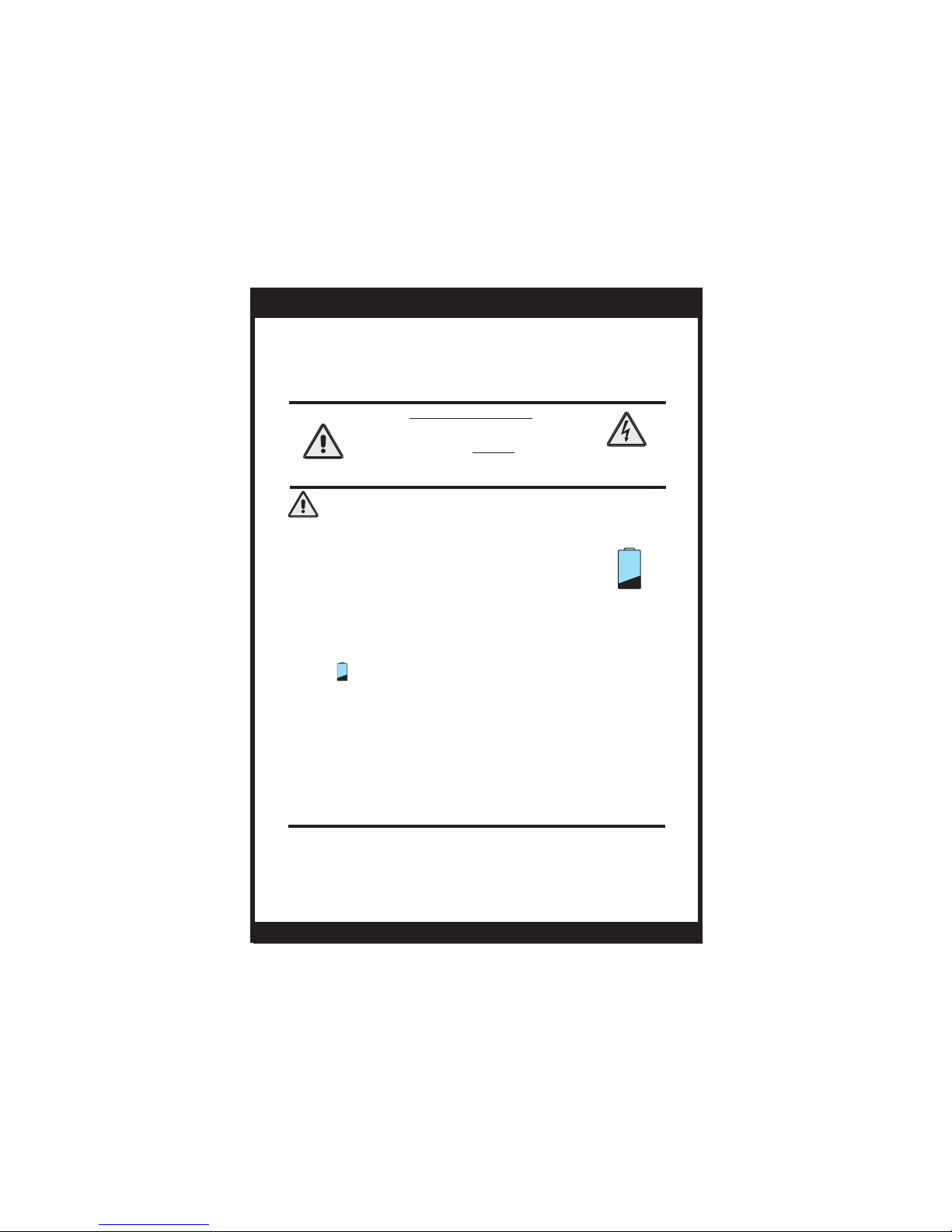
CAUTION
Follow Installation Instructions carefully.
DISCONNECT POWER TO THE HEATER AIR CONDITIONER BEFORE REMOVING
THE OLD THERMOSTAT AND INSTALLING
THE NEW THERMOSTAT.
WARNING
CAUTION
The two Alkaline “AA” batteries must be replaced at
least once every 12 months to ensure proper
operation. The Low Battery icon (fig. 1) will
appear on the display when it is time to replace
the batteries. If the thermostat is connected to
24v power, the batteries should still be installed, but
are not required.
When is displayed the batteries must be replaced
immediately. The manufacturer cannot be liable for
improper operation of the thermostat if the batteries are
not immediately replaced.
Annual battery replacement is especially critical in
locations subject to freezing temperatures. The
thermostat will be unable to turn on the heating system
if the batteries are exhausted.
This device complies with Part 15 of the FCC rules.
Operation is subject to the following two conditions:
(1) This device may not cause harmful interference, and (2)
this device must accept any interference received, including
interference that may cause undesired operation.
FIG. 1
Page 3
Page 4
INSTALLATION INSTRUCTIONS
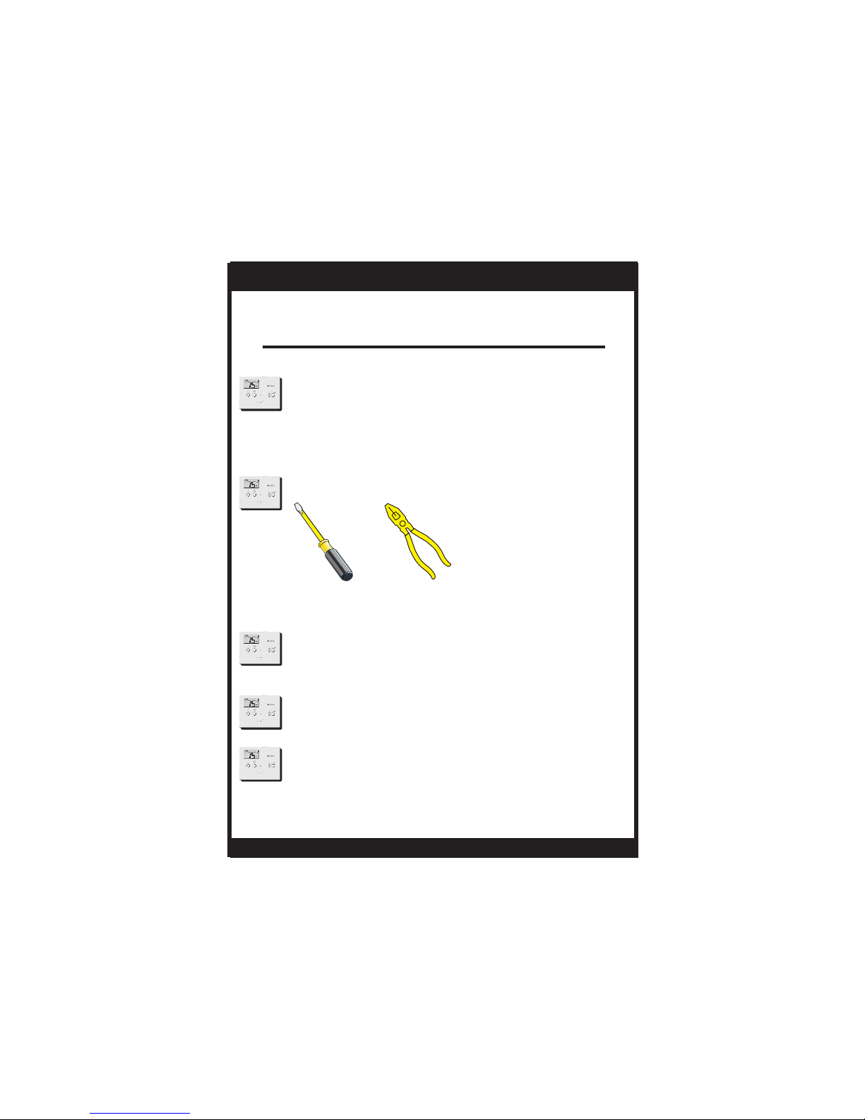
Preparation
Proper installation of the thermostat will be
accomplished by following these step
by step instructions. If you are unsure
about any of these steps, call a qualified
technician for assistance.
These tools will be required:
TSTATG2152-2
Flat Blade
Screwdriver
Make sure your Heat Pump is
working properly before beginning
installation of the thermostat.
Carefully unpack the thermostat.
Save the screws and instructions.
Turn off the power to the Heat Pump
system at the main fuse panel.
Wire cutter
& Stripper
Page 4
Page 5
INSTALLATION INSTRUCTIONS
Remove & Replace
Old Thermostat
Remove the cover of the old thermostat.
If it does not come off easily check for
Loosen the screws holding the thermostat
base or subbase to the wall, and lift away.
Disconnect the wires from the old
thermostat. Tape the ends of the wires
as you disconnect them, and mark them
with the letter of the terminal for easy
reconnection to the new thermostat.
Keep the old thermostat for reference
purposes, until your new thermostat is
functioning properly.
TSTATG2152-2
Page 5
Page 6

INSTALLATION INSTRUCTIONS
TSTATG2152-2
Battery Replacement
The batteries are easily accessible from the battery
door located on the bottom front of the thermostat
(fig. 1). To open the battery slot, pull out on the
battery door (fig. 1) and swing down (fig. 2).
FIG. 1
Pull out
Battery
Door
SET
HEAT
COOL OFF HEAT
BATTERIES
Remove the old batteries and replace with the new
AA alkaline batteries (fig. 3).
AA
Alkaline
:
I
2
:
0
0
PM
S
u
SET
HEA
T
New
batteries
in
Push up on the battery door and snap closed (fig. 4).
FIG. 2
Swing down
FIG. 3
Old
batteries
out
FIG. 4
The batteries must be replaced
immediately when the thermostat
displays the low battery icon (fig.
Push up
1). If the thermostat is connected
to 24v power, the batteries should
still be installed. Installing the batteries when
system powered (24VAC) will keep the clock
running in the event of line power interruption.
Page 6
Snap closed
FIG. 1
Page 7
OWNER'S MANUAL
Wire Connections
If the terminal designations on your old
thermostat do not match those on the
new thermostat, refer to the chart below
or the wiring diagrams that follow.
TSTATG2152-2
Wire from the
old thermostat
terminal marked
C
Rc, R, M, Vr, A
Y1 or Y
W1, W or H
G or F
B
O
Function
Common
Power
Cooling
Auxiliary Heat
Fan
Rev. Valve
(Energize to Heat)
Rev. Valve
(Energize to Cool)
new thermostat
connector marked
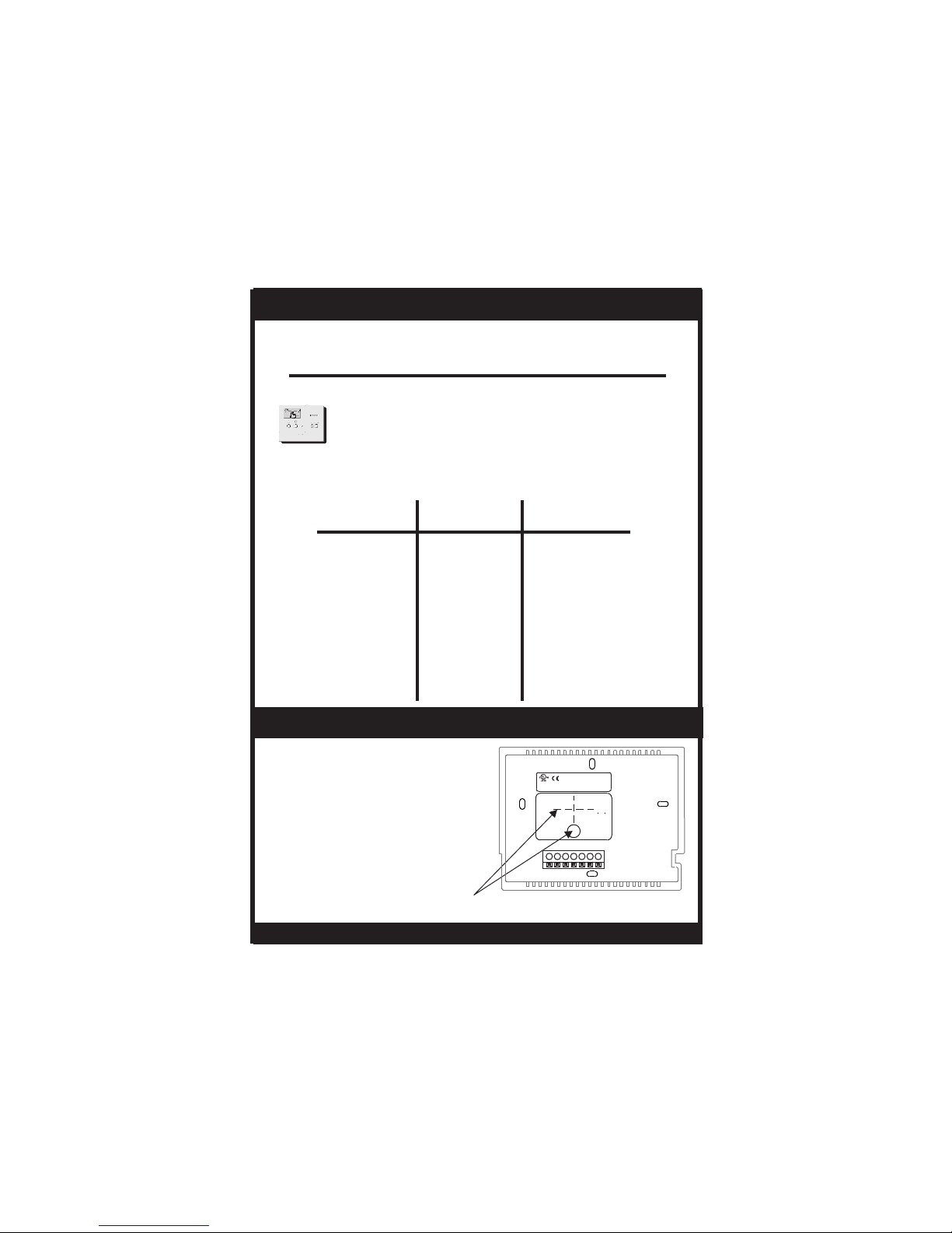
Thermal Insulating Sheet
A label is provided on the
backplate that prevents drafts
originating inside the wall from
entering the thermostat.
These drafts, left unchecked, may
cause incorrect room temperature
readings.
Please do not remove this label
from the thermostat. Insert the wires
through the slots provided in the label
as shown in Fig. 1.
Wire Slots
Page 7
Install on the
C (optional)
R
Y
W
G
B
O
MODEL: TSTATG2152-2
4Z95
97061606
USE SIZE “AA”
MADE IN CHINA
ALKALINE BATTERIES
C R Y W G B O
Fig. 1
Page 8
OWNER'S MANUAL
TSTATG2152-2
Sample Wiring Diagrams
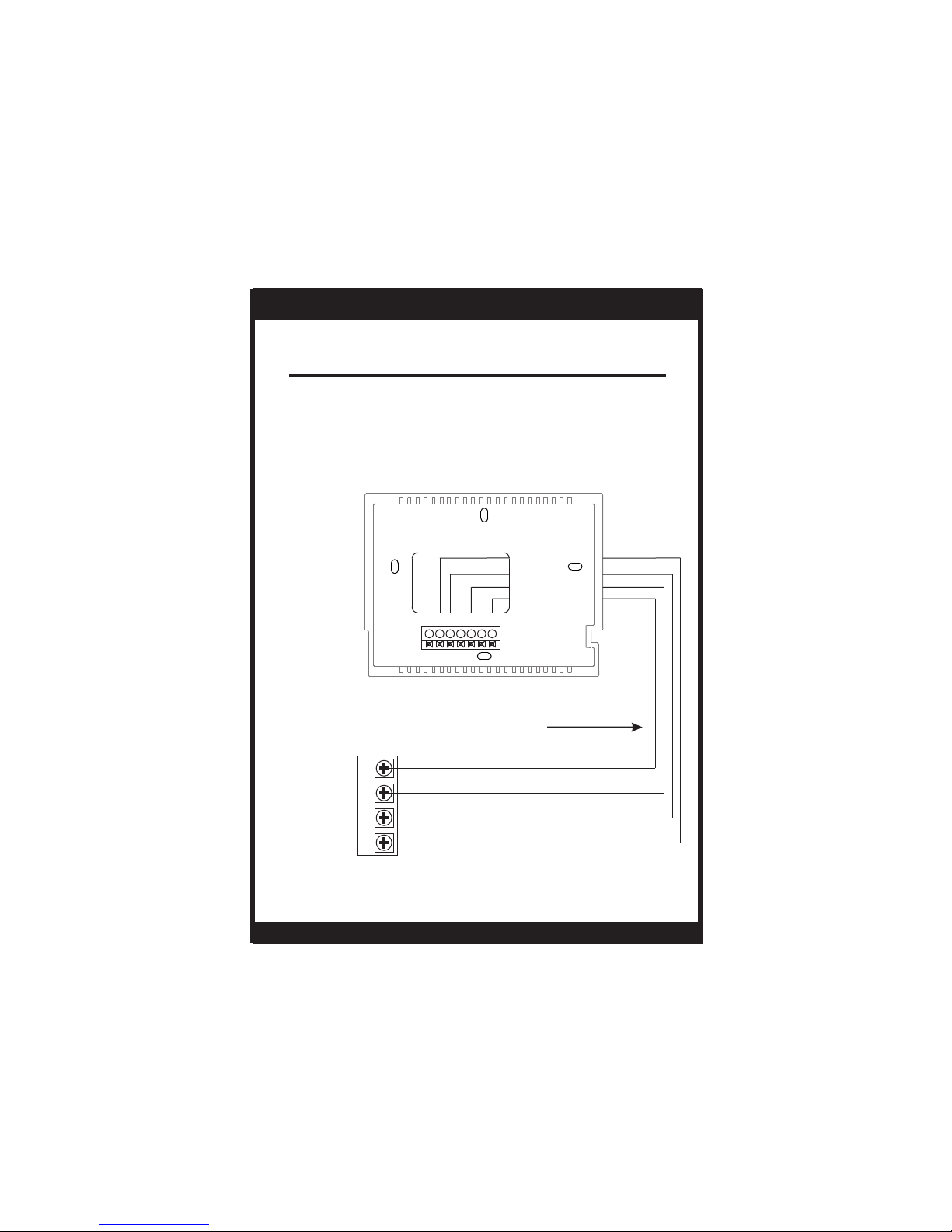
4 Wire, 1 Stage Cooling, 1 Stage Heat-Heat Pump with O reversing valve.
Residential Heat Pumps, split systems & package units, with no auxiliary heat.
Common wire optional
C R Y W G B O
REVERSING VALVE
FAN
G
COMPRESSOR
POWER
Common wire is optional in all installations. If a common wire is not used the
*
thermostat must be powered by two AA alkaline batteries. These batteries
must be replaced (page 11) each year or when the Low Battery indicator is displayed
(page 3).
Y
R O
*
4 Conductor 18 to 22 gauge
unshielded cable from the
thermostat to the equipment.
Page 8
Page 9
OWNER'S MANUAL
TSTATG2152-2
Sample Wiring Diagrams
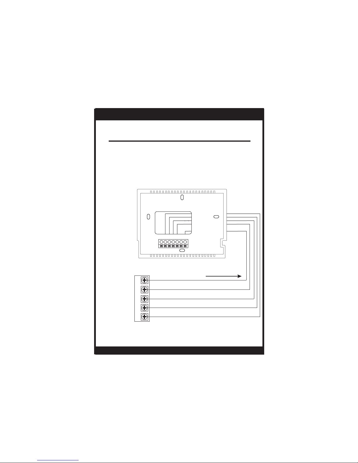
5 Wire, 1 Stage Cooling, 2 Stage Heat-Heat Pump with O reversing valve.
Residential Heat Pumps, split systems & package units, with auxiliary heat.
Common wire optional
C R Y W G B O
REVERSING VALVE
FAN
G
AUXILIARY HEAT
COMPRESSOR
POWER
Common wire is optional in all installations. If a common wire is not used the
*
thermostat must be powered by two AA alkaline batteries. These batteries
must be replaced (page 11) each year or when the Low Battery indicator is displayed
(page 3).
W
Y
R O
*
5 Conductor 18 to 22 gauge
unshielded cable from the
thermostat to the equipment.
Page 9
Page 10

OWNER'S MANUAL
TSTATG2152-2
Sample Wiring Diagrams
4 Wire, 1 Stage Cooling, 1 Stage Heat-Heat Pump with B reversing valve.
Residential Heat Pumps, split systems & package units, with no auxiliary heat.
Common wire optional
C R Y W G B O
FAN
B
G
Y
R
REVERSING VALVE
COMPRESSOR
POWER
Common wire is optional in all installations. If a common wire is not used the
*
thermostat must be powered by two AA alkaline batteries. These batteries
must be replaced (page 11) each year or when the Low Battery indicator is displayed
(page 3).
*
4 Conductor 18 to 22 gauge
unshielded cable from the
thermostat to the equipment.
Page 10
Page 11

OWNER'S MANUAL
TSTATG2152-2
Sample Wiring Diagrams
5 Wire, 1 Stage Cooling, 2 Stage Heat-Heat Pump with B reversing valve.
Residential Heat Pumps, split systems & package units, with auxiliary heat.
Common wire optional
C R Y W G B O
REVERSING VALVE
FAN
G
AUXILIARY HEAT
COMPRESSOR
POWER
Common wire is optional in all installations. If a common wire is not used the
*
thermostat must be powered by two AA alkaline batteries. These batteries
must be replaced (page 11) each year or when the Low Battery indicator is displayed
(page 3).
W
Y
R B
*
5 Conductor 18 to 22 gauge
unshielded cable from the
thermostat to the equipment.
Page 11
Page 12

INSTALLATION INSTRUCTIONS
Test Operation
Turn on the power to the Heat Pump.
On the thermostat, slide the Mode Switch
to HEAT. Press the COOLER or WARMER
button until the set temperature is 10 degrees
above room temperature. The HVAC unit
should energize in the heating mode.
Note: You may need to wait up to five minutes
for heating to energize due to the compressor
lockout feature. There is a two minute minimum run-time for first stage heating.
On the thermostat, slide the Aux Heat
Switch to the NORMAL position. The
Aux Heat icon will appear indicating that
the thermostat has energized Aux Heat
(page 7 of the Owner’s Manual).
TWO STAGE OPERATION - The 2nd stage
of heat (auxiliary heat) is turned on when
the room temperature is equal to or less
than: the setpoint minus the 1st stage
deadband (one degree, adjustable), minus
the 2nd stage deadband (two degrees,
non-adjustable).
Heating
Deadband Deadband
db 1db 2
(non-adj. 2 )
(adj. 1-6 )
TSTATG2152-2
Cooling
Deadband
db 1
(adj. 1-6 )
2nd Stage
turn on
1st Stage
turn on
Page 12
Heat or Cool
Setpoint
1st Stage
turn on
Page 13

INSTALLATION INSTRUCTIONS
Test Operation
On the thermostat, slide the Mode Switch
to COOL. Press the COOLER or WARMER
buttons until the set temperature is 10
degrees below room temperature. The
HVAC unit should energize in the cooling
mode (Page 6 of the Owner’s Manual).
Note: You may need to wait up to five minutes
for cooling to energize due to the compressor
lockout feature.
On the thermostat, slide the Mode Switch to
OFF. Slide the Fan Switch to Fan On. The
fan should turn on and run continuously.
TSTATG2152-2
Page 13
Page 14

INSTALLATION INSTRUCTIONS
Trouble Shooting
SYMPTOM: The slide switches on the thermostat
are very difficult to move.
CAUSE: The backplate of the thermostat is
screwed too tightly into a wall that is not
perfectly flat.
REMEDY: Loosen the screws holding the
thermostat into the wall.
SYMPTOM: The Air Conditioning does not
attempt to turn on.
CAUSE: The cooling setpoint is set too
high, the Mode Switch is not set for
Cool, the batteries are too weak, or the
Aux Heat Switch is set for Emergency.
REMEDY: Consult the Normal Operation
section in the Owner’s Manual to:
Lower the cooling setpoint.
Correct the Mode Switch position.
Replace the batteries.
Slide the Aux Heat Switch to Normal.
TSTATG2152-2
SYMPTOM: The fan does not turn on even though
the compressor has energized.
CAUSE: The Fan Switch is not completely in the
On or Auto position.
REMEDY: Slide the Fan Switch firmly into the On
or Auto position.
Page 14
Page 15

INSTALLATION INSTRUCTIONS
Trouble Shooting
SYMPTOM: Aux Heat does not turn on.
CAUSE: The Aux Heat Switch is set for
Lockout.
REMEDY: Consult the Aux Heat section
of this manual to slide the Aux
Heat Switch to Normal (Page 7 of the
Owner’s Manual).
SYMPTOM: The Heating does not attempt
to turn on.
CAUSE: The heating setpoint is set too
high, the Mode Switch is not set for
Heat, the batteries are too weak, or the
Aux Heat Switch is set for Emergency.
REMEDY: Consult the Normal Operation
section in this manual to:
Raise the heating setpoint.
Correct the Mode Switch position.
Replace the batteries.
Slide the Aux Switch to Normal.
Battery Stat TSTATG2152-2
F
FOR HOME OR OFFICE USE
4Z95
TSTATG2152-2
Tested to Comply
c
with FCC Standards
C
Goodman Manufacturing Company, L.P., reserves the right to discontinue, or change at any time,
Air Conditio ning & Heatin
specifications or designs without notice or without incurring obligations.
Copyright © 2009 • Goodman Company, L.P. • Houston, TexasManufacturing
g
Page 15
P/N 88-846
Rev. 1
Page 16

INSTALLATION INSTRUCTIONS
LIMITED WARRANTY
Models:
TSTAT*1100-2, 2100-2, 1152-2, and 2152-2
*2200C, *3271C, *3272C, *2111, *3272, *3273
TSTATG2152-2
This thermostat is warranted by Goodman Manufacturing Company,
L.P. (“Goodman”) to be free from defects in materials and
workmanship under normal use and maintenance, as described
below:
• The thermostat is warranted for a period of ONE YEAR,
except as provided below.
No warranty continues after the thermostat is removed from the
location where it was originally installed.
No warranty applies to, and no warranty is offered by Goodman on,
any thermostat ordered over the Internet.
The warranty period begins on the date of the original installation. If
that date cannot be verified, the warranty period begins twelve
weeks from the date of manufacture (as indicated by the first four
digits of the serial number (yyww) where “yy” inidcates the year
and “ww” indicates the week of manufacture).
As its only responsibility, and your only remedy, Goodman will,
without charge, replace any thermostat or thermostat part found to
be defective due to workmanship or materials under normal use and
maintenance. For warranty credit, the defective thermostat or
thermostat part must be returned to a Goodman heating and air
conditioning products distributor by a state certified or licensed
contractor.
This warranty does not apply to labor, freight, or any other cost
associated with the service, repair or operation of the unit.
This warranty is in lieu of all other express warranties. ALL IMPLIED
WARRANTIES, INCLUDING BUT NOT LIMITED TO WARRANTIES
OF MERCHANTABILITY AND FITNESS FOR PARTICULAR
PURPOSE, ARE LIMITED TO THE DURATION OF THIS WARRANTY.
Installer Name
Installation Date
Model #
Serial #
For further information about this warranty, contact Goodman Consumer Affairs
at (877) 254-4729 or by mail to 7401 Security Way, Houston, Texas 77040.
© 2009 Goodman Manufacturing Company, L.P.
Page 16
Some states and provinces do not allow limitations on how long an
implied warranty lasts, so the above limitation may not apply to
you.
GOODMAN SHALL IN NO EVENT BE LIABLE FOR INCIDENTAL
OR CONSEQUENTIAL DAMAGES, INCLUDING BUT NOT LIMITED
TO EXTRA UTILITY EXPENSES OR DAMAGES TO PROPERTY.
Some states and provinces do not allow the exclusion or limitation
of incidental or consequential damages, so the above exclusion
may not apply to you.
Goodman is not responsible for:
1. Damage or repairs required as a consequence of faulty
installation or application.
2. Damage as a result of floods, fires, winds, lightning,
accidents, corrosive atmosphere or other conditions
beyond the control of Goodman.
3. Use of components or accessories not compatible with
this thermostat.
4. Products installed outside the United States or Canada.
5. Damage or repairs required as a result of any improper
use, maintenance, operation or servicing.
6. Failure to start due to interruption and/or inadequate
electrical service.
7. Changes in the appearance of the unit that do not affect
its performance.
This warranty gives you specific legal rights, and you may also
have other rights that may vary from state to state or province to
province.
* Amana® & Goodman® brand products
 Loading...