

Page 1
Air Conditioning & Heatin
1 Day Pr og ramma bl e
g
Di gital Thermostat
Mult i Sta ge 2+1
Model TSTATG2111 -2
RES I D ENTIA L
Owner’s Manual
Owner’s Manual
Owner’s Manual
Owner’s Manual
Installation Instructions
Installation Instructions
Installation Instructions
Installation Instructions
Th ank go o dne s s for Goo d man .
and
and
and
and
TM
Page 2

Page 3
CAUTION
Follow the Installation Instructions before proceeding.
Set the thermostat mode to “OFF” prior to changing
settings in setup or restoring Factory Defaults.
This device complies with Part 15 of the FCC Rules. Operation is
subject to the following two conditions: (1) this device may not cause
harmful interference, and (2) this device must accept any interference
received, including interference that may cause undesired operation.
4Z95
Thermostat TSTATG2111-2
F
FOR HOME OR OFFICE USE
Page i
Tested to Comply
c
with FCC Standards
C
Page 4

Page 5

Glossary of Terms
Auto-Changeover: A mode in which the thermostat will turn on the
heating or cooling based on room temperature demand.
Cool Setpoint: The warmest temperature that the space should rise
to before cooling is turned on (without regard to deadband).
Deadband: The number of degrees the thermostat will wait, once a
setpoint has been reached, before energizing heating or cooling.
Differential: The forced temperature difference between the heat set-
point and the cool setpoint.
Heat Setpoint: The coolest temperature that the space should drop
to before heating is turned on (without regard to deadband).
Icon: The word or symbol that appears on the thermostat display.
Mode: The current operating condition of the thermostat (i.e. Off,
Heat, Cool, Auto, Program On).
Non-Programmable Thermostat: A thermostat that does not have
the capability of running Time Period Programming.
Programmable Thermostat: A thermostat that has the capability of
running Time Period Programming.
Temperature Swing: Same as Deadband.
Time Period Programming: A program that allows the thermostat to
automatically adjust the heat setpoint and/or the cool setpoint based
on the time of the day.
Page ii
Page 6

Page 7

Table of Contents
Get to Know Your Thermostat
Quick Start
INSTALLATION INSTRUCTIONS
Sample Wiring Diagrams
Test Operation
USER SETUP
Backlight Operation
Scrolling Display Options
Thermostat Display Options
Emergency Heat
Wireless Accessories
System Runtimes
Time Period Programming
1
5
7
11
14
15
16
16
17
17
18
19
INSTALLER SETUP
Program Mode Operation
Cycles Per Hour
Dry Contact Operation
Factory Defaults
Locking and Unlocking the Keypad
TECHNICIAN SETUP
Sensor Calibration
Equipment Testing
Advanced Output Testing
Advanced Setup Table
Troubleshooting
20
21
21
22
23
24
24
24
25
26
INDEX
27
Page iii
Page 8

Page 9

Get to Know Your Thermostat
Backlit LCD Display
YOUR NAME
Outdoor
80
Am
79
OVERRIDE
MODE
EMERGCY
EMERGCY
HEAT
HEAT
SET CLOCK
RST FLTR
Mode
Button
77
Button
10:38
Down
Button
COOL
DISPLAY ACCESSORY SETUPHOLIDAY
DISPLAY ACCESSORY SETUPSERVICE
Up
HUMIDITY MODE
PROGRAM
OUTDOOR
RUNOFF
HOLD TO SET
Front Panel
Scrolling Display
Heat or Cool
Demand Indicator
Red = Heat
Green = Cool
YOUR NAME
Am
10:38
Outdoor
80
EMERGCY
EMERGCY
Emergency
Heat
79
OVERRIDE
MODE
SET CLOCK
HEAT
HEAT
RST FLTR
Set
Clock
77
COOL
Reset
Filter
OUTDOOR
DISPLAY ACCESSORY SETUPRST FILTER
DISPLAY ACCESSORY SETUPSERVICE
Display
Options
FAN
AUTOON
PROGRAM
RUNOFF
HOLD TO SET
Program
Hold To Set
Accessory
Hidden
Buttons
Fan
On | Auto
Off | Run
Outdoor Temp.
Setup
Page 1
Page 10
Get to Know Your Thermostat
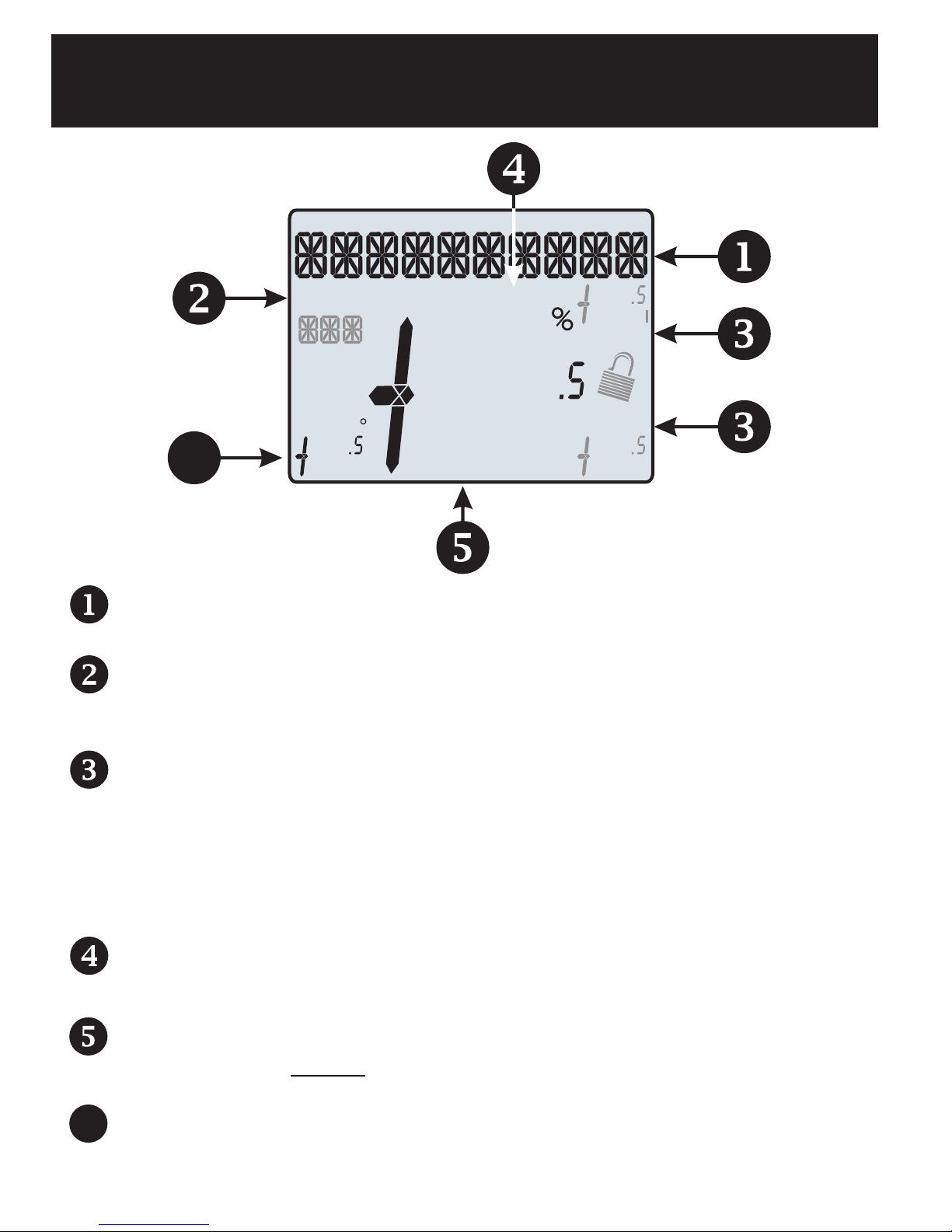
Display Features
Am
18:88
Setup Step
2nd
Stage
Fan On
Outdoor
6
The scrolling display will be used to help you easily navigate the setup
screens in the thermostat.
Clock
Indicates the current time. This clock is also used to program the
time period schedule.
88
Pm
Program On
88
H
88
COOL
AUXHEAT
Lo
88
Mode Indicators
Selects the operational mode of the equipment.
HEAT - Indicates the heating mode.
COOL - Indicates the air conditioning mode.
HEAT & COOL - Indicates the system will automatically change-
over between heat and cool modes as the temperature varies.
OFF - Indicates heating and cooling is turned off.
Program icon
Indicates that Time Period Programming is running or is enabled
to be set.
Room Temperature Display
Indicates the current room temperature and displays the outdoor
temperature when selected.
Outdoor icon
6
Indicates the temperature displayed is from the optional outdoor
sensor.
Page 2
Page 11
Get to Know Your Thermostat
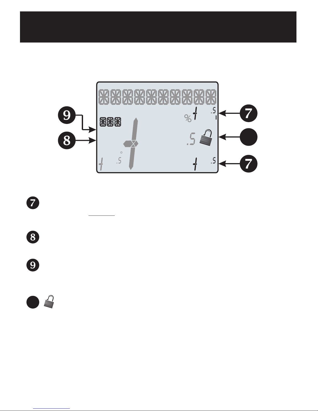
Display Features
Am
18:88
Setup Step
2nd
Stage
Fan On
Outdoor
Pm
88
Desired Set Temperature
Indicates desired room temperature(s). Also displays the highest
and lowest temperatures for the day.
2nd Stage icon
Indicates what stage of heating is currently energized.
Program On
88
88
COOL
A HEAT UX
88
H
10
Lo
Setup Step icon
Indicates the step number when the thermostat is in the
setup mode.
10
icon
Indicates the keypad has been locked.
Page 3
Page 12

Get to Know Your Thermostat
Display Features
Am
18:88
Setup Step
2nd
Stage
Fan On
Outdoor
Pm
88
AuxHeat icon
Indicates 2nd stage electric strip heat is being used when the
thermostat is programmed for Heat Pump operation.
Fan On icon
Indicates constant, continuous fan operation.
When Fan On is not lit - indicates the fan will only operate when
necessary to heat or to cool.
Program On
88
88
COOL
A HEAT UX
88
H
Lo
Page 4
Page 13

Quick Start
During Setup and Programming:
Press the UP or DOWN buttons to modify the selection.
Press the MODE button to advance and confirm through the setup steps.
Setting the Clock
Press the SET CLOCK button. Adjust the clock using the UP or DOWN
buttons. Press the SET CLOCK button to confirm settings.
TIP: To adjust the time by hours press and hold the FAN button while pressing
the UP or DOWN buttons.
Selecting the Heat or Cool Mode
Select mode by pressing the MODE button.
Heating Only - The HEAT setting indicates the temperature the room has to reach
before the furnace will turn on to heat the room.
MODE
MODE
Cooling Only - The COOL setting indicates the temperature the room has to reach
before the air conditioner will turn on to cool the room.
Heating or Cooling (Auto-Changeover) - AUTO will automatically select heat or cool
based on room temperature demand.
OFF - OFF indicates both heating and air conditioning systems are turned off.
NOTE - This thermostat has a fixed two degree deadband. With a Cool setpoint of
72 degrees Fahrenheit, cooling will energize at a room temperature of 74 degrees.
With a Heat setpoint of 68 degrees Fahrenheit, heating will energize at 66 degrees.
Page 5
Page 14

Quick Start
Selecting Your Desired Temperature
AUTO-CHANGEOVER MODE - Pressing the UP or DOWN buttons in Auto or Program
mode will adjust both the heat and cool setpoints simultaneously. To adjust heat and
cool setpoints individually, choose HEAT mode to adjust the heat setpoint and COOL
mode to adjust the cool setpoint, then return to AUTO mode.
HEAT OR COOL MODE - Pressing the UP or DOWN buttons in Heat or
Cool mode will adjust only the heat or cool setpoints individually displayed.
Using the Fan Button
Fan On indicates constant fan operation.
You may turn the fan on even if the thermostat is in the OFF mode. Pressing the FAN
button toggles this feature on or off.
Viewing the Outdoor Temperature Sensor
OUTDOOR TEMP - Press the OUTDOOR button to view the current
outdoor temperature. Press the OUTDOOR button again to return to
normal operation.
Note: If no outdoor sensor is connected, 2 dashes [- -] will appear with
the first button press.
Using the Reset Filter Button
Reset Filter - Press the RST FILTER button to view the current filter
runtime. Press the OUTDOOR button to reset the filter runtime counter to 0.
Press the RST FILTER button again to return to normal operation.
Page 6
Page 15

Installation Instructions
Remove & Replace the Old Thermostat
To install the thermostat properly, please follow these step by
step instructions. If you are unsure about any of these steps,
call a qualified technician for assistance.
Assemble tools: Flat blade screwdriver, wire cutters and wire
strippers.
Make sure your Heater/Air Conditioner is working properly
before beginning installation of the thermostat.
Carefully unpack the thermostat. Save the screws, any brackets, and instructions.
Turn off the power to the Heating/Air Conditioning system at
the main fuse panel. Most residential systems have a separate
breaker for disconnecting power to the furnace.
Remove the cover of the old thermostat. If it does not come off
easily, check for screws.
Loosen the screws holding the thermostat base or subbase to the
wall and lift away.
Disconnect the wires from the old thermostat. Tape the ends
of the wires as you disconnect them, and mark them with the
letter of the terminal for easy reconnection to the new thermostat.
Keep the old thermostat for reference purposes, until your new
thermostat is functioning properly.
Page 7
Page 16

Wire Connections
Installation Instructions
Wire Connections
If the terminal designations on your old thermostat
do not match those on the new thermostat, refer
to the chart below or the wiring diagrams
that follow.
Wire from the
old thermostat
terminal marked
G or F Fan G
Y1, Y or C
W1, W or H
C
O/B
W2
Ck1
CKGND
Function
connector marked
Cooling Y1
Heating
PowerRh, R, M, Vr, A R
Common
Rev. Valve
2nd Stage Heat
Dry Contact Switch
Dry Contact Switch
Install on the
new thermostat
W1/O/B
C
W1/O/B*
W2
DRY CONTACT
DRY CONTACT
S1, OUT -
S2, OUT +
* O/B is used if your system is a Heat Pump.
Outdoor Sensor
Outdoor Sensor
Page 8
OUTDOOR
OUTDOOR
Page 17

Installation Instructions
The TSTATG2111-2 Thermostat Backplate
DRY
SENSOR
W2
W1/O/B
R
C
OUTDOOR
CONTACT
Y1
G
W1/O/B
W2
C
R
1st stage heat/reversing valve
2nd stage heat circuit
24 VAC common
24 VAC Return
IMPORTANT: This thermostat requires both
R (24 VAC Return) and C (24 VAC Common) be
connected to the backplate terminals.
OUTDOOR
SENSOR
DRY
CONTACT
Y1
G
Page 9
Outdoor Sensor
connections
Dry Contact
connections
1st stage compressor
Fan relay
Page 18

Installation Instructions
Explanation of Thermostat Jumpers
Jumpers are located on the back of the thermostat
J1
J2
GAS
J3
ELEC
GAS/ELEC
HEATPUMP
RV=O
RV=B
J2
GAS/ELEC
OR
HEATPUMP
RV=O
OR
RV=B
RV=O
RV=B
GAS/ELEC
J1
HEATPUMP
ELEC
GAS
GAS/ELEC
RV=O
J1J2J3
HEATPUMP
RV=B
This jumper configures the thermostat to control a conventional
gas/electric system or a heat pump. If your system is anything
other than a heat pump, leave this jumper set for GAS/ELEC.*
*For some commercial heat pumps, this jumper will need to
be set for GAS/ELEC. Consult the commercial heat pump literature.
When J1 is configured to control a heat pump, this jumper (J2)
must be set to control the appropriate reversing valve. If RV=O
is chosen, the W1/O/B terminal will energize in cooling. If RV=B
is chosen, the W1/O/B terminal will energize in heating.
When J1 is set for GAS/ELEC:
(FAN)
This jumper (J3) controls how the thermostat will control the
Fan (G) terminal in heating mode. When GAS is chosen, the
J3
GAS
(FAN)
GAS
OR
thermostat will not energize the Fan (G) terminal in heating.
ELEC
ELEC
When ELEC is chosen the thermostat will energize the fan in
heating.
Page 10
Page 19

Installation Instructions
Sample Wiring Diagrams
Conventional Heating and Cooling Systems
3 Wire, Heat Only
Residential & Commercial 1 Stage Heating
with no Fan.
R
C
W1/O/B
J1 =
J2 =
J3 =
5 Wire, 1 Stage Cooling, 1 Stage Heat
Residential & Commercial 1 Stage Cooling,
with 1 stage Gas Heat.
R
C
W1/O/B
Y1
G
24VAC Power
24VAC Common
1st Stage Heat
Gas/Elec
O (not used)
Gas
24VAC Power
24VAC Common
1st Stage Heat
1st Stage Cool
Fan
4 Wire, Cool Only
Residential & Commercial 1 Stage Cooling.
R
C
Y1
G
J1 =
J2 =
J3 =
5 Wire, 1 Stage Cooling, 1 Stage Heat
Residential & Commercial 1 Stage Cooling,
with 1 stage Electric Heat.
R
C
W1/O/B
Y1
G
24VAC Power
24VAC Common
1st Stage Cool
Fan
Gas/Elec
O (not used)
Gas
24VAC Power
24VAC Common
1st Stage Heat
1st Stage Cool
Fan
J1 =
J2 =
J3 =
Gas/Elec
O (not used)
Gas
6 Wire, 1 Stage Cooling, 2 Stage Heat
R
C
W1/O/B
W2
Y1
G
J1 =
J2 =
J3 =
J1 =
J2 =
J3 =
Residential & Commercial 1 Stage Cooling,
with 2 stage Gas Heat.
24VAC Power
24VAC Common
1st Stage Heat
2nd Stage Heat
1st Stage Cool
Fan
Gas/Elec
O (not used)
Gas
Gas/Elec
O (not used)
Electric
Page 11
Page 20

Installation Instructions
Sample Wiring Diagrams
Heat Pump Systems
5 Wire, 1 Stage Cooling, 1 Stage Heat
Residential & Commercial Heat Pump with
‘O’ Reversing Valve
R 24VAC Power
C 24VAC Common
W1/O/B Reversing Valve
Y1 1st Stage Compressor
(Cool or Heat)
G Fan
J1 = Heat Pump
J2 = O
J3 = Gas
6 Wire, 1 Stage Cooling, 2 Stage Heat
Residential & Commercial Heat Pump with
‘O’ Reversing Valve
R 24VAC Power
C 24VAC Common
W1/O/B Reversing Valve
Y1 1st Stage Compressor
(Cool or Heat)
W2 Aux Heat
G Fan
J1 = Heat Pump
J2 = O
J3 = Electric
Page 12
Page 21

Installation Instructions
Sample Wiring Diagrams
Dry Contact and Outdoor Sensor
W2
W1/O/B
10K Thermistor
Outdoor Sensor
TSTATGAC-WS
R
C
DRY
OUTDOOR
SENSOR
CONTACT
Y1
G
Condensate Pan
Float Switch
Page 13
Page 22

Installation Instructions:
This thermostat has a diagnostic feature that enables testing of all
outputs. This feature is contained in Technician Setup.
To enter Technician Setup, press and hold the SETUP button for 5 seconds until
all the icons appear. Follow the next steps to view settings and test equipment.
Press MODE to view the version numbers of the thermostat.
1.
2.
Press MODE again to view the jumper settings and current state of
the Dry Contact terminals.
3.
Press MODE again and the scrolling display will read “TURN ON
EQUIPMENT?” Press UP for Yes or DOWN for No.
If Yes is chosen, press UP to turn on heat or DOWN to turn on
Cooling. The scrolling display will read “NOTHING ON.” Next:
Test Operation
Press UP to turn on and cycle up through the heating stages.
Press DOWN to turn the heating stages off. Press MODE to exit.
Press DOWN to turn on and cycle down through the cooling stages.
Press UP to turn the cooling stages off. Press MODE to exit.
4.
Press MODE until “CALIBRATE SENSORS?” appears on the scrolling display. Press UP for Yes or DOWN for No. Use UP or DOWN
to modify your selection.
To exit Technician Setup at any time, press the SETUP button. Technician Setup
will automatically exit after 10 minutes if no buttons are pressed.
Page 14
Page 23

User Setup:
Backlight Operation
How to Change Settings in the Setup Screens
To enter Advanced Setup, press the SETUP button, then press MODE. Use the
UP or DOWN buttons to adjust the value of your selection. Press MODE to
advance to the next setup step. Press SETUP again to leave the setup screens.
Backlight (Setup Step 3)
The thermostat backlight may be set to be always on, on temporarily with any button
press, on throughout the evening, or always off. (For always off, see Backlight Level)
Press the SETUP button, then press MODE repeatedly until the Backlight setup
step appears. Use the UP or DOWN buttons to make selection. Press MODE to
advance to the next step. Press SETUP to leave the setup screens.
Backlight Off - Backlight turns on with any button press and turns off after 8 seconds.
Backlight On - Backlight is on continuously.
Backlight 6pm to 6am - Backlight turns on at 6pm and turns off at 6am.
Backlight Level (Setup Step 4)
The backlight can be adjusted between always off and seven levels of brightness.
Press the SETUP button, then press MODE repeatedly until the Backlight setup
step appears. Use the UP or DOWN buttons to adjust the brightness. Press
MODE to advance to the next step. Press SETUP to leave the setup screens.
Language (Setup Step 16)
Setup step instructions on the scrolling display can be set for English, Spanish, or
French.
Press the SETUP button, then press MODE repeatedly until the Language setup
step appears. Use the UP or DOWN buttons to make selection. Press MODE to
advance to the next step. Press SETUP to leave the setup screens.
Page 15
Page 24

User Setup:
Scrolling Screen and Display Options
Scrolling Display Method (Setup Step 17)
This option allows the user to choose how the scrolling text is displayed. Options are:
Scrolling
Press the SETUP button, then press MODE repeatedly until the Scrolling Method
setup step appears. Use the UP or DOWN buttons to make a selection. Press
MODE to advance to the next step. Press SETUP to leave the setup screens.
Example of “Whole Words Centered”:
A
Scroll Letters Slow
Scroll Letters Fast
Scroll Words Slow
Scroll Words Fast
SERVICE
12:00
Pm
Program On
74
COOL
12:00
Non-Scrolling
Whole Words Slow
Whole Words Fast
Words Centered Slow
Words Centered Fast
B
FILTER
Pm
Program On
1
74
COOL
Outdoor
78 68
72
Display
This option allows the user to “de-clutter” the thermostat display screen by removing
icons from the main display. The room temperature will always be shown. Service
information may also be viewed by pressing and holding the DISPLAY button.
Each press of the DISPLAY button
will remove icons. Keep pressing
DISPLAY to make icons reappear.
Press and hold DISPLAY for 5 seconds
to view a name and phone number to
call for service.
Any removed icons will be displayed temporarily when a setting change is made.
HEAT
Outdoor
78 68
Page 16
HEAT
72
Show All
Remove Scrolling Text
Remove Current Time
Remove Outdoor Temp
Remove Setpoint
Remove Mode
Page 25

User Setup
Emergency Heat
To initiate the Emergency Heat feature, Press and hold the EMERGCY HEAT button
for 2 seconds. During Emergency Heat operation the thermostat will turn on the fan
and auxiliary stages of heat when there is a demand for heat. The 1st stage of
heating and all stages of cooling will be unavailable. To exit Emergency Heat,
press the EMERGCY HEAT button.
Accessory
The optional RF Module
must be installed to link
and view wireless accessories.
The Emergency Heat function is only
available if your thermostat is set to
control a Heat Pump.
The ACCESSORY button allows the user to view wired and wireless sensors
and “link” these and other wireless devices to the thermostat via an optional RF
module. Press the ACCESSORY button to enter the Accessory setup screen.
Press UP to view linked and wired accessories. Follow the instructions included
with the wireless accessory to begin linking process. Next, press DOWN to
enter the wireless linking mode. Press MODE to initiate linking. Press
ACCESSORY to return to the main screen. NOTE: A wired outdoor sensor’s
temperature reading is updated once every minute; a wireless outdoor sensor’s
temperature reading is updated once every 5 minutes.
Page 17
Page 26

User Setup:
These setup steps allow the user to monitor equipment runtimes and program
service alerts.
System Runtimes
RUNTIME
Runtime hours or days appear
in the clock display.
Service Filter Runtime (Setup Steps 5-6, 12-13)
Press the SETUP button, then press MODE repeatedly until the desired setup
step appears. Use the UP or DOWN buttons to make selection. Press MODE
to advance to the next step. Press SETUP to leave the setup screens.
30
05
Setup Step
Current Service Filter Runtime Hours (Setup Step 5) - This counter keeps track of
the number of hours of fan runtime in the Heating mode, Cooling mode, and in stand
alone Fan operation. Press FAN to reset.
Current Service Filter Calendar Days (Setup Step 6) -
total number of calendar days that have elapsed since the counter was reset to help
the user track Fan runtime. Press FAN to reset.
Set Service Filter Runtime Hours (Setup Step 12) - This timer allows the user to
specify the number of hours the fan will run before the “Replace Filter” alert will be
displayed. Press DOWN continuously until OFF is displayed to disable this alert.
Set Service Filter Calendar Days (Setup Step 13) - This timer allows the user to
specify the number of calendar days that will elapse before the “Replace Filter” alert
will be displayed. Press DOWN continuously until OFF is displayed to disable this
feature.
UV Lamp Runtime (Setup Steps 10, 14)
Current UV Lamp Calendar Days (Setup Step 10) -
number of calendar days that have elapsed to help the user track UV lamp runtime.
Press FAN to reset.
This counter displays the
This counter displays the total
Set UV Lamp Calendar Days (Setup Step 14) - This timer allows the user to specify
the number of calendar days the UV Lamp will operate before the “Replace UV Lamp”
alert will be displayed. Press DOWN continuously until OFF appears to disable this
alert.
Page 18
Page 27

User Setup:
To enter Time Period Programming
screens, Press and hold PROGRAM
until the scrolling prompt appears.
OFF - Time Period Program is off.
RUN - Time Period Program is running.
HOLD TO SET - Press and hold
PROGRAM to make Time Period
Programming changes.
Time Period Programming
OFF
RUN
HOLD TO SET
Programming a Daily Schedule
SET PROGRA
M
This thermostat features four programmable time periods per 24 hour day:
Morning, Day, Evening, and Night. The start time for each time period is
adjustable. The stop time for each time period is the start time for the next.
Select Morning Start Time - Press the UP or DOWN buttons to adjust the time of day
desired. Press MODE to advance to the next step.
Select Morning Cool Setpoint - Press the UP or DOWN buttons to adjust the cool
setpoint desired. Press MODE to advance to the next step.
Select Morning Heat Setpoint - Press the UP or DOWN buttons to adjust the heat
setpoint desired. Press MODE to advance to the next step.
Repeat Start Time and Setpoint programming for Day, Evening, and Night.
Press the PROGRAM or MODE Button to exit Time Period Programming
Page 19
Page 28

Installer Setup
How to Change Settings in the Setup Screens
To enter Advanced Setup, press the SETUP button, then press MODE. Use the
UP or DOWN buttons to adjust the value of your selection. Press MODE to
advance to the next setup step. Press SETUP again to leave the setup screens.
Selecting Your Program Mode (Setup Step 1)
This thermostat may be configured to be programmable or non-programmable.
Non Program - No advanced time period programming available.
1 Day Program - Allows one 24 hour day to be programmed. This same schedule will
be repeated everyday the program is set to run.
Selecting Your Available Modes (Setup Step 2)
Auto-Changeover - Allows the thermostat to turn on heating or cooling based on
room temperature demand. Also allows the manual selection of HEAT only or COOL
only and OFF.
Heat and Cool - Allows the thermostat to turn on heating or cooling depending on
which one has been manually selected. Auto-Changeover is not available when this is
selected.
Heat Only - Allows the thermostat to only turn on HEAT or OFF modes.
Cool Only - Allows the thermostat to only turn on COOL or OFF modes.
Page 20
Page 29

Installer Setup
Cycles Per Hour (Setup Step 21)
The Cycles Per Hour setting may limit the number of times per hour your
HVAC unit may energize. For example, at a setting of 6 cycles per hour the
HVAC unit will only be allowed to energize once every 10 minutes. The Cycles
Per Hour limit may be overridden and reset by pressing the UP or DOWN
buttons on the thermostat. Settings are No Limit, 2, 3, 4, 5, or 6.
Compressor Minimum Off Minutes (Setup Step 22)
This feature allows the user to set a minimum off time for the compressor. Settings are
5 mins., 3 mins., or 0 mins.
Minimum Heat/Cool Setpoint Difference(Setup Step 23)
This feature allows the user to set the minimum gap between Heat and Cool setpoints
in AUTO mode. Select from 0 to 6. If setup step 2 is not set for AUTO-CHANGEOVER,
this step will not appear.
Fahrenheit or Celsius (setup step 57)
This feature allows the thermostat to display temperature in Fahrenheit or Celsius.
Dry Contact Operation(setup step 71)
Dry Contact Polarity (Setup Step 71)
Open (Normally Open) - The dry contact
is open until the connected device closes
the circuit.
‘Idle’ ‘Active’
Dry
Contact
When the dry contact is active, the thermostat will lockout the compressor terminal(s)
and “SERVICE DRAIN PAN” will appear on the display.
Dry
Dry
Contact
Contact
Closed (Normally Closed) - The dry
contact is closed until the connected
device opens the circuit.
‘Idle’ ‘Active’
Dry
Dry
Contact
Contact
Dry
Contact
Press Fan To Clear All Messages (setup step 76)
This feature allows the user to clear all current error messages from the display.
Page 21
Page 30

Installer Setup
Resetting the Thermostat to the
Factory Default Settings (for default values see page 25)
If, for any reason, you desire to return all the stored settings back to
the factory default settings, follow the instructions below.
WARNING: This will reset all Time Period and Advanced
Programming to the default settings. Any information entered
prior to this reset may be permanently lost.
Press and hold SETUP for 5 seconds. All icons will appear on the display.
Keep pressing the SETUP
button until you see this
screen.
After all the icons appear, release SETUP. Press and hold FAN for 5 seconds.
DEFAULTS will appear on the display.
Keep pressing the FAN
button until you see this
screen.
18:88
Setup Step
Stage
Fan On
Outdoor
DEFAULTS
2nd
88
Am
Program On
Pm
88
88
A HEAT UX
88
H
COOL
Lo
After DEFAULTS appears, release FAN. Press SETUP to return to normal
operation.
Page 22
Page 31

Installer Setup
Locking/Unlocking the Keypad
To prevent unauthorized use of the thermostat, the front panel buttons may be
disabled. To disable, or ‘lock’ the keypad, press and hold the MODE button.
While holding the MODE button, press the UP and DOWN buttons together.
The icon will appear on the display, then release the buttons.
Press all three
2:00
buttons in the order
outlined above for
keypad lockout
To unlock the keypad,
the MODE button, press the UP and DOWN buttons together. The
icon will disappear from the display, then release the buttons.
press and hold the MODE button. While holding
I
Outdoor
85
Am
78
74
COOL SET
HEAT ETS
68
Page 23
Page 32

Technician Setup
To enter Technician Setup, press and hold the SETUP button for 5 seconds.
After all the icons appear, press MODE. The version number of the thermostat
will appear in the scrolling text. Press MODE to advance to the next step. Use
the UP or DOWN buttons to adjust the value of your selection. To leave
Technician Setup, press SETUP.
Hold for 5 seconds All icons appear Press MODE to advance
through the setup steps
Am
Program On
18:88
Fan On
Outdoor
Pm
Setup Step
2nd
Stage
88
88
88
A HEAT UX
88
H
COOL
Press UP or DOWN
to adjust the selection
Lo
Technician Setup is for diagnostic and testing purposes and is intended for use
by a qualified technician. See page 14 for more detailed instructions.
Technician Setup contains the following options:
View the version number of the thermostat.
View the jumper setting of J1 (Gas/Electric or Heat Pump), J2 (Reversing Valve:
RV=O or RV=B), and J3 (Fan: Gas or Electric) jumpers located on the back of the
thermostat. (Remove thermostat from backplate for access)
View the state of the Dry Contact terminal.
Turn on equipment outputs for testing.
Calibrate thermostat sensor.
Page 24
Page 33

Advanced Setup Table
Step#
Description
Df = Factory Default Setting
Pg#
Range
Df
1
2
3
4
5
6
10
12
13
14
16
17
21
22
23
57
71
76
Prog Mode
Available Modes
Backlight
Backlight Level
Current Service Filter Runtime Hours
Current Service Filter Calendar Days
Current UV Lamp Calendar Days
Set Service Filter Runtime Hours
Set Service Filter Calendar Days
Set UV Lamp Calendar Days
Language
Scrolling Method
Cycles Per Hour
Compressor Minimum Off Minutes
Minimum Heat/Cool Setpoint Difference
F/C
Dry Contact Polarity
Press Fan To Clear All Messages
Non,1
20
Heat/Cool/Auto/Off,
20
Heat/Cool/Off,Heat/Off,
Cool/Off
On,Off,6pm-6am
15
Off-7 levels of brightness
15
0-1999
18
0-1999
18
0-1999
18
18
0-1950
18
0-720
18
0-720
English,Espanol,Francais
15
16
L-R Slow,L-R Fast,Word
L-R Slow,Word L-R Fast,
Whole Word L Slow,
Whole Word L Fast,
Whole Word Ctr Slow,
Whole Word Ctr Fast
21
No Limit,2,3,4,5,6
21
0,3,5
21
0-6
21
Fahrenheit,Celsius
21
Open,Closed
21
N/A
1
Heat/Cool/
Auto/Off
Off
Level 5
0
0
0
0
0
0
English
Whole
Word Ctr
Fast
6
5
2
F
Open
N/A
Page 25
Page 34

TroubleShooting
SYMPTOM: The air conditioning does not attempt to turn on.
CAUSE: The compressor timer lockout may prevent the air
conditioner from turning on for a period of time.
REMEDY: Consult the Owner's Manual in the Installer Setup
section to defeat the Cycles Per Hour (page 21).
SYMPTOM: The display is blank.
CAUSE: Lack of proper power.
REMEDY: Make sure the power is on to the furnace and that
you have 24vac between R & C.
SYMPTOM: The air conditioning does not attempt to turn on.
CAUSE: The cooling setpoint is set too high.
REMEDY: Lower the cooling setpoint.
SYMPTOM: The heating does not attempt to turn on.
CAUSE: The heating setpoint is set too low.
REMEDY: Raise the heating setpoint.
SYMPTOM: When controlling a residential heat pump, and
asking for cooling, the heat comes on.
CAUSE: The thermostat reversing valve jumper is set for “B”.
REMEDY: Set the reversing valve jumper for “O”.
SYMPTOM: When calling for cooling, both the heat and cool
come on.
CAUSE: The thermostat equipment jumper is configured for
“HP” and the HVAC unit is a Gas/Electric.
REMEDY: Set the equipment jumper for “Gas”.
SYMPTOM: When the Program button is pressed, the display
reads “DISABLED”.
CAUSE: Program mode is set to “NON PROGRAM”.
REMEDY: Set Program Mode (Setup 1) to 1 Day.
See Selecting Your Program Mode (page 20).
Page 26
Page 35

Index
Alerts
see Runtime
Accessory, 17
Auto
adjust temperature, 6
changeover, 6, 20
fan, 6
mode, 5, 20
AuxHeat icon, 4
program, 1, 19
reset filter, 1, 6
set clock, 1, 5
setup, 1, 15, 20
up (warmer), 1, 5
C, 25
Calibration, 14, 24
Celsius, 21, 27
Clock
Day
programming, 19
setting, 19
Differential
heat and cool, 21
Disabled Keypad
see Keypad Lockout
Drain Pan Overflow
Alarm, see Dry Contact
display, 2
b reversing valve, 10,
24
Backplate, 9
Buttons
accessory, 1, 17
down (cooler) 1, 5
display, 1, 16
emergency heat, 1, 17
fan, 1, 6,
front panel, 1
mode, 1, 5
setting, 5
Compressor Lockout,
21
Cool
1st stage
deadband,
electric/heat pump,
5
icon, 2
indicator, 1
mode, 2, 5
setpoint, 2, 6, 19
Condensate Drain
Pan, 21
Dry Contact
operation, 21
polarity, 21
service pan, 21
Electric Heating
AuxHeat icon, 2
jumper setting, 10
Emergency Heat, 17
outdoor, 1, 6
Cycles Per Hour, 21
Page 27
Page 36

Index
Heat
Factory Defaults
caution, i
settings, 25
resetting, 22
Fahrenheit, 21
Fan
button function, see
Buttons
on during heat, see
Electric Heat
on icon, 4
2nd stage heat, see
1st stage
deadband, see
Deadband
emergency heat,
17
electric strip heat,
17
pump,
10
mode, 2, 5
setpoint, 6, 19
Heat Pump
AuxHeat, 12
emergency heat, 17
electric/heat
indicator, 1
Keypad Lockout, 23
LCD, 1
Locked Indication,
see Keypad Lockout
Emergency Heat
Gas/Electric Furnace
jumper, 10
Green Indicator, 1
jumper setting, 10
multi-stage, 11, 12
Jumpers
ELEC, 10
electric heat, 10
gas electric, 10
heat pump, 10
reversing valve,10
viewing,14, 24
Manual
changeover, 20
cool, 20
heat, 20
Mode, 2, 5, 20
Multi-stage
Operation, 11, 12
Page 28
Page 37

Index
Non-Programmable
Thermostat, 20
Normally
Open/Closed,
dry contact, 21
O Reversing Valve
see Reversing Valve
Off Mode, 2, 5
Outdoor
button, see Buttons
icon, 2
sensor, 6, 13
Programming a Daily
Schedule, 19
Reset
thermostat settings,
see Factory Defaults
runtime
fan/filter, 18
UV light, 18
Reversing Valve, 10
Runtime
resetting, see Reset
setting,
service filter, 18
UV light, 18
viewing,
service filter, 18
UV light, 18
pan, see Dry Contact
UV light, see Reset
Set Clock, see Clock
Setpoint
cool, see Cool
heat, see Heat
Simplest Operation, 5
Technician Setup, 14,
24
Thermostat Sensor
calibrate, 14, 24
Time, see Clock
Time Schedule, see
Program
viewing, 6
Pan, Service
see Dry Contact
Polarity, see Dry Contact
Programmable
Thermostat, 20
Schedule
Daily, see Program
Sensor
outdoor, see Outdoor
thermostat, see
Thermostat
Service
filter, see Reset
Page 29
UV Light
resetting, 18
runtime, see Runtime
setting, see Runtime
Warranty, 30
Page 38

Warranty
Five-Year Warranty - This Product is warranted to be free from defects in material and
workmanship. If it appears within five years from the date of original installation, whether or not
actual use begins on that date, that the product does not meet this warranty, a new or
remanufactured part, at the manufacturer’s sole option to replace any defective part, will be
provided without charge for the part itself provided the defective part is returned to the distributor
through a qualified servicing dealer.
THIS WARRANTY DOES NOT INCLUDE LABOR OR OTHER COSTS incurred for diagnosing, repairing,
removing, installing, shipping, servicing or handling of either defective parts or replacement
parts. Such costs may be covered by a separate warranty provided by the installer.
THIS WARRANTY APPLIES ONLY TO PRODUCTS IN THEIR ORIGINAL INSTALLATION LOCATION AND
BECOMES VOID UPON REINSTALLATION.
LIMITATIONS OF WARRANTIES – ALL IMPLIED WARRANTIES (INCLUDING IMPLIED WARRANTIES OF
FITNESS FOR A PARTICULAR PURPOSE AND MERCHANTABILITY) ARE HEREBY LIMITED IN DURATION TO
THE PERIOD FOR WHICH THE LIMITED WARRANTY IS GIVEN. SOME STATES DO NOT ALLOW LIMITATIONS
ON HOW LONG AN IMPLIED WARRANTY LASTS, SO THE ABOVE MAY NOT APPLY TO YOU. THE
EXPRESSED WARRANTIES MADE IN THIS WARRANTY ARE EXCLUSIVE AND MAY NOT BE ALTERED,
ENLARGED, OR CHANGED BY ANY DISTRIBUTOR, DEALER, OR OTHER PERSON WHATSOEVER.
ALL WORK UNDER THE TERMS OF THIS WARRANTY SHALL BE PERFORMED DURING NORMAL WORKING
HOURS. ALL REPLACEMENT PARTS, WHETHER NEW OR REMANUFACTURED, ASSUME AS THEIR
WARRANTY PERIOD ONLY THE REMAINING TIME PERIOD OF THIS WARRANTY.
THE MANUFACTURER WILL NOT BE RESPONSIBLE FOR:
1. Normal maintenance as outlined in the installation and servicing instructions or owner’s
manual, including filter cleaning and/or replacement and lubrication.
2. Damage or repairs required as a consequence of faulty installation, misapplication, abuse,
improper servicing, unauthorized alteration or improper operation.
3. Failure to start due to voltage conditions, blown fuses, open circuit breakers or other
damages due to the inadequacy or interruption of electrical service.
4. Damage as a result of floods, winds, fires, lightning, accidents, corrosive environments or
other conditions beyond the control of the Manufacturer.
5. Parts not supplied or designated by the Manufacturer, or damages resulting from their use.
6. Manufacturer products installed outside the continental U.S.A., Alaska, Hawaii, and
Canada.
7. Electricity or fuel costs or increases in electricity or fuel costs for any reason whatsoever
including additional or unusual use of supplemental electric heat.
8. ANY SPECIAL INDIRECT OR CONSEQUENTIAL PROPERTY OR COMMERCIAL
DAMAGE OF ANY NATURE WHATSOEVER. Some states do not allow the exclusion of
incidental or consequential damages, so the above may not apply to you.
This warranty gives you specific legal rights and you may also have other rights which may vary
from state to state.
Page 30
Page 39

Notes:
Printed on recycled paper.
P/N 88-890 Rev. 1
 Loading...