

Page 1
®
TECHNICAL MANUTECHNICAL MANU
TECHNICAL MANU
TECHNICAL MANUTECHNICAL MANU
ALAL
AL
ALAL
SSX 14 SEER
Condensing Units
• Refer to Service Manual RS6200006 for installation, operation, and troubleshooting information.
• All safety information must be followed as provided in the Service Manual.
• Refer to the appropriate Parts Catalog for part number information.
• Models listed on page 3.
This manual is to be used by qualified, professionally trained HVAC technicians only. Goodman does not
assume any responsibility for property damage or personal injury due to improper service procedures
or services performed by an unqualified person.
RT6113003r11
January 2012
Copyright © 2006-2012 Goodman Manufacturing Company, L.P.
Page 2
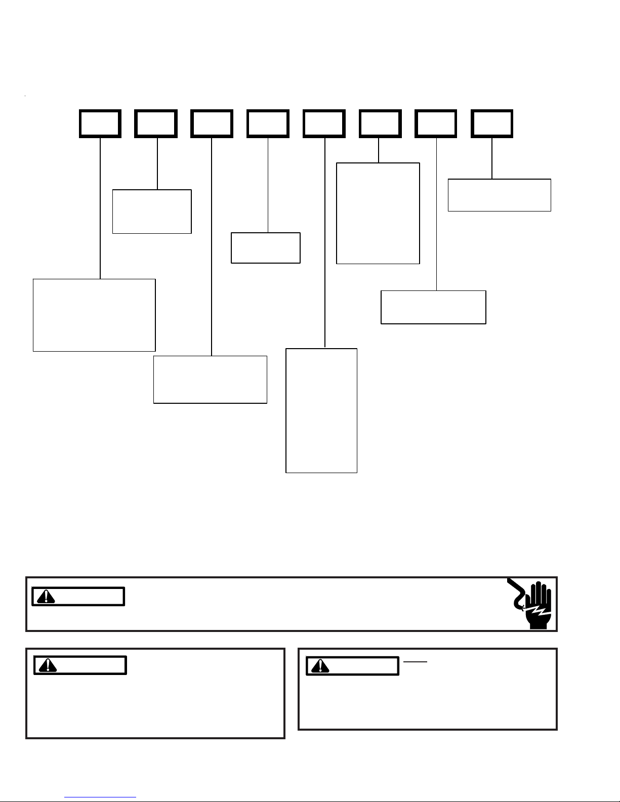
PRODUCT IDENTIFICATION
The model number is used for positive identification of component parts used in manufacturing. Please use this number
when requesting service or parts information.
SSX140241AA
ELECTRICAL:
PRODUCT
FAMILY:
S: Spli t System
SEER:
SEER Ratin g
1: 208-230v
1ph /60 H z
3: 208-230v
3ph /60 H z
4: 460v
3ph /60 H z
MI NOR REVISION:
A : In itial Re lea se
BRAND:
®
S: Goodman
(Hi gh Feature Set Model )
Brand
G: Goodman® Brand
(Sta ndard Featur e Set Model)
PRODUCT TYPE:
X: Condenser R-410A
Z: Heat Pu m p R-410A
MAJOR RE V ISI ON:
A : In itial Re lea se
NOMINAL
CAPACITY
018: 1.5 Tons
024: 2 Tons
030: 2.5 tons
036: 3 Tons
042: 3.5 Tons
048: 4 Tons
060: 5 tons
WARNING
WARNING
WARNING
arising from improper service or service procedures. If
you install or perform service on this unit, you assume
responsibility for any personal injury or property damage
which may result. Many jurisdictions require a license to
install or service heating and air conditioning equipment.
2
Disconnect ALL power before servicing or installing this unit. Multiple power
sources may be present. Failure to do so may cause property damage, personal
injury or death.
Goodman will not be responsible
for any injury or property damage
WARNING
HIGH VOLTAGE!
WARNING
WARNING
fied by the Air-Conditioning, Heating, and Refrigeration
Institute (AHRI) may use this information. Attempting to
install or repair this unit without such background may
result in product damage, personal injury or death.
ONLY individuals meeting (at a
mininum) the requirements of an
"Entry Level Technician" as speci-
Page 3
PRODUCT IDENTIFICATION
The model number is used for positive identification of component parts used in manufacturing. Please use this number
when requesting service or parts information.
SSX140181A*
SSX140241A*
SSX140301A*
SSX140361A*
SSX140421A*
SSX140481A*
SSX140601A*
SSX140181B*
SSX140241B*
SSX140301B*
SSX140361B*
SSX140421B*
SSX140481B*
SSX140421C*
* Indicates minor revision & is not used for order entry or inventory management
WARNING
WARNING
The United States Environmental Protection Agency (“EPA”) has issued various regulations regarding the introduction and disposal of refrigerants introduced into this unit. Failure to follow
these regulations may harm the environment and can lead to the imposition of substantial fines.
These regulations may vary by jurisdiction. Should questions arise, contact your local EPA office.
WARNING
WARNING
Serious property damage, personal injury, reduced unit
performance and/or hazardous conditions may result
from the use of such non-approved devices.
Do not connect or use any device
that is not design certified by
Goodman for use with this unit.
WARNING
WARNING
do not store combustible materials or use gasoline or
other flammable liquids or vapors in the vicinity of this
appliance.
To prevent the risk of property
damage, personal injury, or death,
3
Page 4
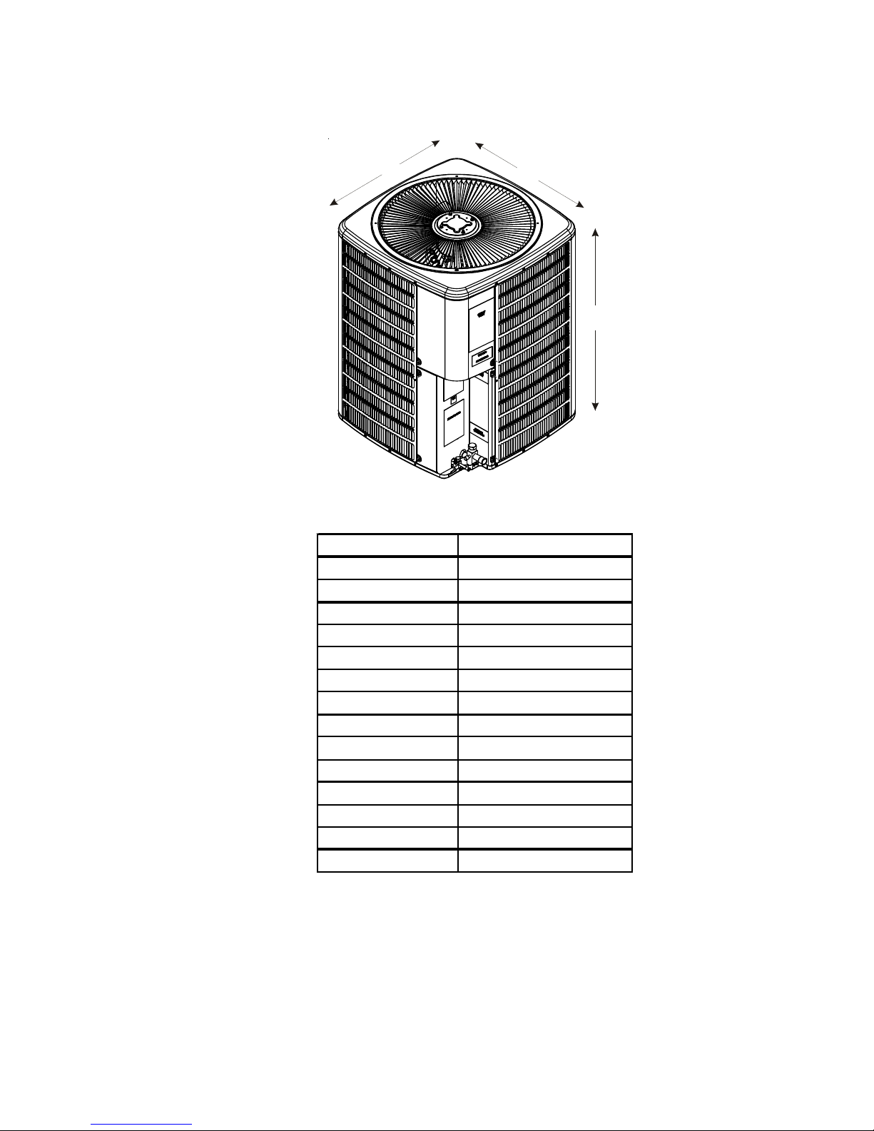
PRODUCT DESIGN
A
A
SSX14 models are available in 1 1/2 through 5 ton sizes and
use R-410A refrigerant. They are designed for 208/230 volt
single phase applications.
The condenser air is pulled through the condenser coil by a
direct drive propeller fan. This condenser air is then discharged out of the top of the cabinet.
These units are designed for free air discharge, so no additional resistance like duct work shall be attached.
The suction and liquid line connections on present models
are of the sweat type for field piping with refrigerant type copper. Front seating valves are factory installed to accept the
field run copper. The total refrigerant charge for a normal installation is factory installed in the condensing unit. SSX units
are charged for the matching evaporator coil and a 15 foot
refrigerant line set.
Systems should be properly sized by heat gain and loss
calculations made according to methods of the Air Conditioning Contractors Association (ACCA) or equivalent. It is
the contractors responsibility to ensure the system has adequate capacity to heat or cool the conditioned space.
SSX models use the Copeland Scroll "Ultratech" Series compressors which are specifically designed for R-410A refrigerant. There are a number of design characteristics which are
different from the traditional reciprocating and/or scroll compressors.
"Ultratech" Series scroll compressors will not have a discharge thermostat, some of the early model scroll compressors required discharge thermostats.
Due to their design Scroll compressors are inherently more
tolerant of small quantities of liquid refrigerant.
NOTE: Even though the compressor section of a Scroll compressor is more tolerant of liquid refrigerant, continued
floodback or flooded start conditions may wash oil from the
bearing surfaces causing premature bearing failure.
"Ultratech" Series scroll compressors use "POE" or
polyolester oil which is NOT compatible with mineral oil based
lubricants like 3GS. "POE" oil must be used if additional oil
is required.
Operating pressures and amp draws may differ from standard reciprocating and/or scroll compressors. This information may be found in the "Cooling Performance Data" section.
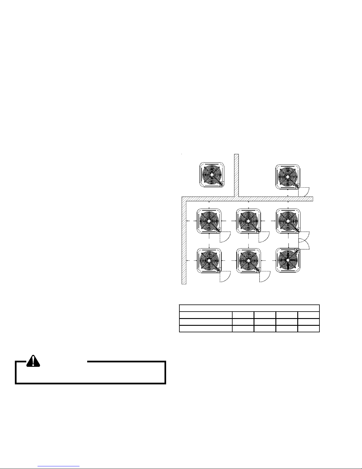
minimum of 60 inches between the top of the unit and
the obstruction(s). The specified dimensions meet require-
ments for air circulation only. Consult all appropriate regulatory codes prior to determining final clearances.
Another important consideration in selecting a location for
the unit(s) is the angle to obstructions. Either side adjacent
the valves can be placed toward the structure provided the
side away from the structure maintains minimum service clearance. Corner installations are strongly discouraged.
DO NOT locate the unit:
– Directly under a vent termination for a gas appliance.
– Within 3 feet of a clothes dryer vent.
– Where the refreezing of defrost water would create a
hazard.
– Where water may rise into the unit.
NOT
RECOMMENDED
B B B
AA AAA
C
AA
A
Model Type
Residential 10" 10" 18" 20"
Light Commercial 12" 12" 18" 24"
AA
Minimum Airflow Clearance
AA
C
AA
CC
BCA
B
AA
OK!
OK!
OK!
OK!
OK!
OK!
WARNING
To avoid possible injury, explosion or death, practice
safe handling of refrigerants.
Special consideration must be given to location of the condensing unit(s) in regard to structures, obstructions, other
units, and any/all other factors that may interfere with air
circulation. Where possible, the top of the unit should be
completely unobstructed; however, if vertical conditions require placement beneath an obstruction there should be a
4
Page 5
PRODUCT DESIGN
DIMENSIONS
SSX140**1*
D
W
H
Model Dimensions - W x D x H
SSX140181A* 26" x 26" x 32¼"
SSX140181B* 26" x 26" x 27½"
SSX140241A* 26" x 26" x 32½"
SSX140241B* 26" x 26" x 32½"
SSX140301A* 29" x 29" x 32¼"
SSX140301B* 29" x 29" x 32½"
SSX140361A* 29" x 29" x 34¼"
SSX140361B* 29" x 29" x 32½"
SSX140421A* 35½" x 35½" x 38¼"
SSX140421B* 29" x 29" x 38¼"
SSX140421C* 29" x 29" x 36¼"
SSX140481A* 35½" x 35½" x 38¼"
SSX140481B* 35½" x 35½" x 36¼"
SSX140601A* 35½" x 35½" x 38¼"
5
Page 6

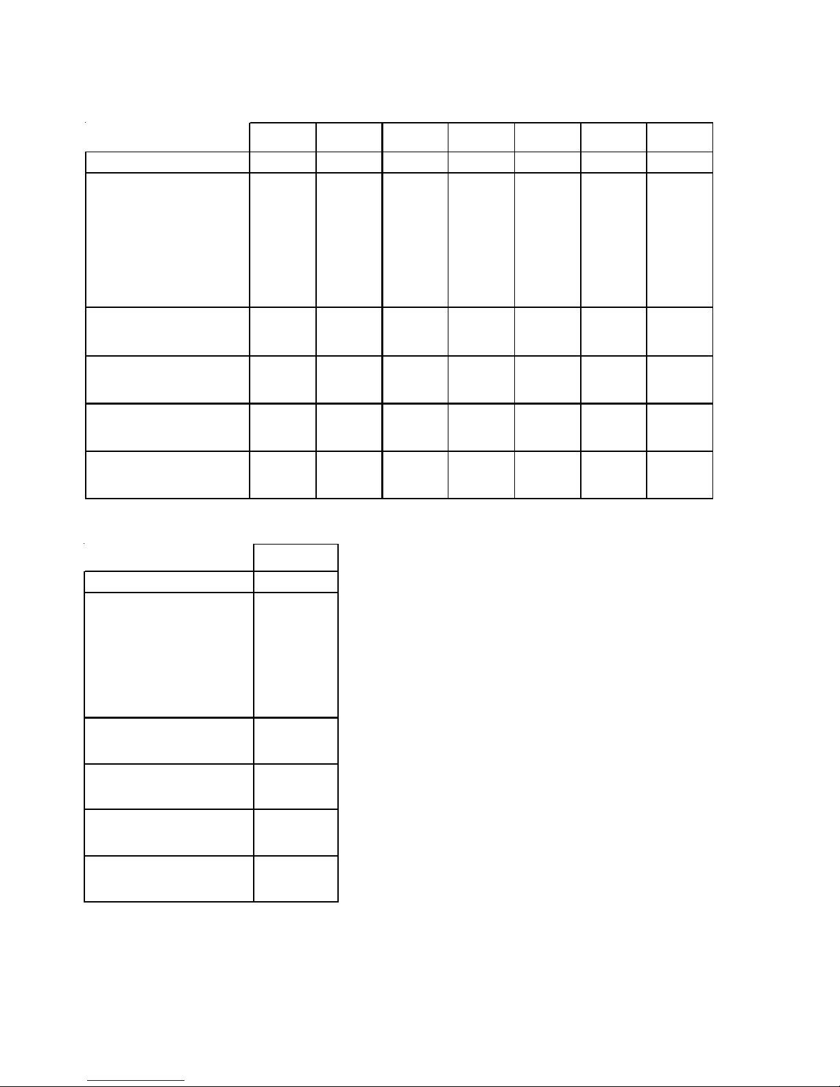
CONDENSING UNIT SPECIFICATIONS
p
y
SSX140181A* - SSX140361A*
SSX14018
AA/AB
Cooling Capacity, BTUH 18,000 18,000 24,000 24,000 30,000 30,000 36,000 36,000
Compressor
R. L. A m ps 9. 0 0 9. 00 13 . 4 13.4 12. 8 12 . 8 14.1 14. 1
L.R . A m ps 48.0 48 .0 58.3 58. 3 64 . 0 64.0 77.0 77. 0
Low Pressure Switch
Open
Close
High Pressure Switch
Open
Close
Condens er Fan Motor
Horsepower 1/12 1/12 1/12 1/12 1/6 1/6 1/4 1/4
F.L. A mp s 0.6 0.6 0.6 0.6 1.5 1.5 1.6 1.6
Liquid Line, Inches O.D.* 3/8"3/8"3/8"3/8"3/8"3/8"3/8"3/8"
Suction Line, Inches O.D.* 3/4"3/4"3/4"3/4"3/4"3/4"7/8"7/8"
Re f rigerant Charge 13 0. 0 121.0 135 .0 126 .0 140.0 131 .0 155.0 146. 0
Power Supply 208/230-60-1 208/230-60-1 208/230-60-1 208/230-60-1 208/230-60-1 208/230-60-1 208/230-60-1 208/230-60-1
M inimum Cir cuit Am pac ity
Maximum Overcurrent Device
E lec t ri cal Con duit Siz e
Power Supply (In c hes ) 1/2 or 3/4 1/2 or 3/4 1/2 or 3/4 1/2 or 3/4 1/2 or 3/4 1/2 or 3/4 1/2 or 3 /4 1/2 or 3/4
Approximat e Shi pping Wei ght 178 178 178 178 195 195 199 199
(1)
(2)
22 PSIG
50 PSIG
610 PSIG
420 PSIG
11.8 11.8 17.4 17.4 17.5 17.5 19.2 19.2
20 20 30 30 30 30 30 30
SSX14018ACSSX14024
22 PSIG
50 PSIG
610 P S I G
420 P S I G
AA/AB
22 PSIG
50 PSIG
610 PSIG
420 PSIG
SSX140241ACSSX140301
22 PSIG
50 PSIG
610 PSIG
420 PSIG
AA/AB/AC
22 PSIG
50 PSIG
610 PSIG
420 PSIG
SSX140301
AD/AE
22 PSIG
50 PSIG
610 PSIG
420 PSIG
SSX140361
AA/AB/AC
22 PSIG
50 PSIG
610 PSIG
420 PSIG
SSX140361
AD/AE
22 PSIG
50 PSIG
610 P SIG
420 P SIG
SSX140421A* - SSX140601A*
SSX140421
AA/AB/AC
Cooling Capacity, BTUH 42,000 42,000 48,000 48,000 60,000 60,000
Compressor
R. L. A m ps
L.R . A m p s
17.9 17.9 19.8 19.8 26.4 26.4
112.0 112.0 109.0 109.0 134.0 134.0
Low Pressure Swit ch
Open
Close
22 PSIG
50 PSIG
High Pressure Switch
Open
Close
610 P S IG
420 P S IG
Condens er Fan Motor
Horsepower 1/4 1/4 1/4 1/4 1/4 1/4
F.L. Amps 1.6 1.6 1.6 1.6 1.6 1.6
Liqui d Lin e, Inch es O.D .* 3 /8 " 3/8 " 3/8" 3/8" 3/8 " 3/8"
Suct ion Lin e, Inch es O.D .* 7/8 " 7/8" 7/8 " 7/8" 7/8" 7/8 "
Refrigerant Charge
180.0 174.0 195.0 186.0 280.0 271.0
Power Supply 208/230-60-1 208/230-60-1 208/230-60-1 208/230-60-1 208/230-60-1 208/230-60-1
Minim um Circuit Am
Maximum Overcurrent Device
acit
(1)
(2)
24.0 24.0 26.4 26.4 34.6 34.6
40 40 40 40 60 60
Electrical Conduit Size
Powe r Supply (In c hes ) 1/2 or 3/4 1/2 or 3/ 4 1/ 2 or 3/4 1/2 or 3/4 1/2 or 3/4 1/2 or 3/4
Approximate S hipping Wei ght
207 207 242 242 280 280
SSX140421
AD/AE
22 PSIG
50 PSIG
610 P S I G
420 P S I G
SSX140481
AA/AB/AC
22 PSIG
50 PSIG
610 PSIG
420 PSIG
SSX140481
AD/AE
22 PSIG
50 PSIG
610 PSIG
420 PSIG
SSX140601
AA/AB/AC
22 PSIG
50 PSIG
610 PSIG
420 PSIG
SSX140601
AD/AE
22 PSIG
50 PSIG
610 PSIG
420 PSIG
*
Up to 24' in equivalent line length
(1)
Wire size should be determined in accordance with National Electrical Codes; extensive wire runs will require larger wire sizes.
(2)
Maximum Overcurrent Protection Device: MUST use Time Delay Fuses or HACR type Circuit Breaker of the same size as noted.
NOTE: This data is provided as a guide, it is important to electrically connect the unit and properly size fuses/
circuit breakers and wires in accordance with all national and/or local electrical codes. Use copper wire only.
6
Page 7
CONDENSING UNIT SPECIFICATIONS
A
p
y
SSX140[18-48]1B*
SS X140181B*SSX140241B*SSX140301B*SSX140361BASS X140361BBSSX140421B*SSX140481
Co oling C ap ac ity , BTU H 18,0 00 2 4, 000 28,800 34,60 0 34 ,6 00 40,000 46,00 0
Com pressor
R.L. A m ps 9.0 0 13.4 12.8 14.1 1 4.1
L.R. A m ps 48 .0 58.3 64.0 77.0 7 7.0
17.9 19.9
11 2.0 109.0
Low Pr ess ure Sw itch
Open
Close
22 PSIG
50 PSIG
22 PSIG
50 PSIG
22 PSIG
50 PSIG
22 PSIG
50 PSIG
55 PSIG
95 PSIG
22 PSIG
50 PSIG
High Pressure Switch
Open
Close
610 PSIG
420 PSIG
61 0 PSIG
42 0 PSIG
610 PSIG
420 PSIG
610 PS IG
420 PS IG
610 PSIG
420 PSIG
610 PSIG
420 PSIG
Conden ser Fan Motor
Ho rsepower 1 /6 1/12 1/6 1/6 1 /6 1/6 1/ 4
F.L . Amps 1.1 0.6 1.1 1.1 1.1 1 .0 1.5
Liqui d Line , Inc he s O.D .* 3/8" 3 /8 " 3/ 8" 3/ 8" 3/8" 3/8" 3/ 8"
Suction Line, Inches O.D.* 3/4"3/4"3/4"7/8"7/8"7/8"7/8"
Re frigerant Char ge 73 .0 91.0 96.0 101.0 101 .0 167.0 147.0
Pow er Supp ly 208/23 0- 60-1 20 8 /2 30-60-1 208/ 230-60-1 208/ 230 -60 -1 208 /230-60-1 208/230-6 0 -1 20 8/ 230 -60- 1
Minimum Circuit Ampacity
(1)
Maximum Overcurrent Device
(2)
12 .4 17.5 17.1 18.7 1 8.7
2 0 30 30 30 30
23.4 26.4
40 45
Electrical Conduit Size
Pow er Suppl y (Inches) 1/2 or 3/4 1 /2 or 3/4 1/2 or 3/4 1/2 or 3/4 1/2 or 3/4 1/2 or 3/4 1/2 or 3/4
App rox imat e S hi ppi n g We ight 146 15 6 172 172 172
207 236
B*
55 PSIG
95 PSIG
610 PSIG
420 PSIG
SSX140421C*
SSX140421
C
Cooling Capacity, BTUH 40,000
Compressor
R.L. A m ps
L.R. Amp s
Low Pressure Switch
Open
Close
High Pres sure Swit ch
Open
Close
Condenser Fan Motor
Horsepower 1/6
F.L. Amps 1.1
Liquid Line, Inches O.D .* 3/8"
Su ction Line, In c hes O.D.* 7/8"
Refrigerant Charge 140.0
Power Supply 208/230-60-1
Minimum Ci rcuit A m
Maximum Overcurrent Device
Electrical Conduit Size
Power Supply (Inches) 1/2 or 3/4
Appr o x im ate S hip p i ng W e ight
acit
(1)
(2)
16.7
79.0
22 PSIG
50 PSIG
61 0 P SIG
42 0 P SIG
22.0
35
184
*
Up to 24' in equivalent line length
(1)
Wire size should be determined in accordance with National Electrical Codes; extensive wire runs will require larger wire sizes.
(2)
Maximum Overcurrent Protection Device: MUST use Time Delay Fuses or HACR type Circuit Breaker of the same size as noted.
NOTE: This data is provided as a guide, it is important to electrically connect the unit and properly size fuses/
circuit breakers and wires in accordance with all national and/or local electrical codes. Use copper wire only.
7
Page 8
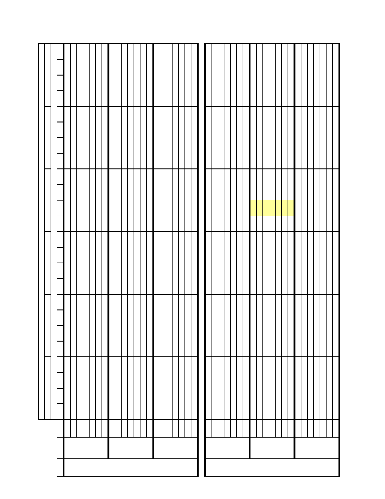
COOLING PERFORMANCE DATA
COOLING OPERATION
SSX140181A*
EXPANDED PERFORMANCE DATA
5.8 6.0 5.8 5.9 6.1 6.4 6.1 6.3 6.5 6.7
5.6
Outdoor Ambient Temperature
Entering Indoor Wet Bulb Temperature
5.7 5.9 5.7 5.9 6.1 6.3 6.1 6.2 6.4 6.7
5.5
5.7 5.9 5.7 5.8 6.0 6.3 6.0 6.2 6.4 6.6
353 361 364 392 397 406 408 439 445 455
5.5
348
65 75 85 95 105 115
S/T 0.71 0.59 0.41 - 0.74 0.62 0.43 - 0.76 0.63 0.44 - 0.78 0.65 0.45 - 0.81 0.68 0.47 - 0.82 0.68 0.47 -
MBh 17.6 18.3 20.0 - 17.2 17.9 19.6 - 16.8 17.4 19.1 - 16.4 17.0 18.6 - 15.6 16.2 17.7 - 14.4 15.0 16.4 -
MODEL: SSX140181A* / CA*F3131B6A* + TXV, Design Subcooling @ ARI 95°F Conditions, 7° - 9°F @ the Serv. Vlv.
IDB*Airflow 596367715963677159636771596367715963677159636771
Delta T171511 - 171511 - 171511 - 171511 - 171511 - 161411 -
676 KW 1.27 1.30 1.33 - 1.36 1.39 1.43 - 1.44 1.47 1.51 - 1.51 1.54 1.59 - 1.57 1.60 1.65 - 1.62 1.65 1.70 -
HI PR 226 243 246 - 255 274 278 - 290 312 316 - 330 355 360 - 372 400 405 - 416 448 454 -
AMPS 4.4 4.5 4.6 - 4.7 4.8 5.0 - 5.1 5.2 5.4 - 5.5 5.6 5.8 - 5.8 5.9 6.1 - 6.1 6.3 6.5 -
S/T 0.68 0.57 0.39 - 0.70 0.59 0.41 - 0.72 0.60 0.42 - 0.74 0.62 0.43 - 0.77 0.65 0.45 - 0.78 0.65 0.45 -
MBh 17.1 17.7 19.4 - 16.7 17.3 19.0 - 16.3 16.9 18.5 - 15.9 16.5 18.1 - 15.1 15.7 17.2 - 14.0 14.5 15.9 -
LO PR 116 120 131 - 1 19 12 3 135 - 124 127 139 - 127 131 143 - 129 133 146 - 133 137 149 -
Delta T181512 - 181612 - 181612 - 181612 - 181512 - 171411 -
8
HI PR 223 240 244 - 253 272 275 - 287 309 313 - 327 352 357 - 368 396 401 - 412 443 450 -
AMPS 4.3 4.4 4.6 - 4.7 4.8 4.9 - 5.1 5.2 5.4 - 5.4 5.5 5.7 - 5.7 5.9 6.1 - 6.1 6.2 6.4 -
LO PR 115 119 129 - 1 18 12 2 133 - 122 126 138 - 126 130 141 - 128 132 144 - 131 135 148 -
70 601 KW 1.26 1.29 1.32 - 1.35 1.38 1.42 - 1.43 1.46 1.50 - 1.50 1.53 1.57 - 1.55 1.59 1.63 - 1.60 1.64 1.69 -
Delta T181612 - 181612 - 181612 - 181612 - 181612 - 171511 -
526 KW 1.25 1.28 1.31 - 1.34 1.37 1.41 - 1.42 1.45 1.49 - 1.49 1.52 1.56 - 1.54 1.57 1.62 - 1.59 1.62 1.67 -
HI PR 221 238 241 - 250 269 273 - 284 306 310 - 324 348 353 - 364 392 397 - 408 439 445 -
AMPS 4.3 4.4 4.5 - 4.6 4.7 4.9 - 5.0 5.1 5.3 - 5.4 5.5 5.7 - 5.7 5.8 6.0 - 6.0 6.2 6.4 -
LO PR 114 117 128 - 1 17 12 1 132 - 121 125 136 - 124 128 140 - 127 131 143 - 130 134 146 -
S/T 0.65 0.55 0.38 - 0.68 0.57 0.39 - 0.70 0.58 0.40 - 0.72 0.60 0.42 - 0.75 0.62 0.43 - 0.75 0.63 0.43 -
MBh 15.8 16.4 17.9 - 15.4 16.0 17.5 - 15.1 15.6 17.1 - 14.7 15.2 16.7 - 14.0 14.5 15.9 - 12.9 13.4 14.7 -
S/T 0.810.720.550.350.840.750.570.370.860.770.580.370.890.79 0.60 0.39 0.92 0.82 0.62 0.40 0.93 0.83 0.63 0.40
MBh 17.9 18.5 20.0 21.5 17.5 18.0 19.5 21.0 17.1 17.6 19.1 20.5 16.7 17.2 18.6 20.0 15.9 16.3 17.7 19.0 14.7 15.1 16.4 17.6
HI PR 226 243 246 252 255 274 278 284 290 312 316 323 330 355 360 368 372 400 405 414 416 448 454 464
AMPS4.44.54.64.84.74.85.05.25.15.25.45.65.5
Delta T2018151020181510201815102019 15 10 20 18 15 10 19 17 14 10
676 KW 1.271.301.331.371.361.391.431.471.441.471.511.561.511.54 1.59 1.63 1.57 1.60 1.65 1.70 1.62 1.65 1.70 1.76
LO PR 116 120 131 139 119 123 135 143 124 127 139 148 127 131 143 152 129 133 146 155 133 137 149 159
S/T 0.770.690.520.340.800.720.540.350.820.730.560.360.850.76 0.57 0.37 0.88 0.79 0.59 0.38 0.89 0.79 0.60 0.39
MBh 17.4 17.9 19.4 20.8 17.0 17.5 19.0 20.3 16.6 17.1 18.5 19.9 16.2 16.7 18.1 19.4 15.4 15.8 17.2 18.4 14.3 14.7 15.9 17.1
HI PR 223 240 244 249 253 272 275 282 287 309 313 320 327 352 357 365 368 396 401 410 412 443 450 459
AMPS4.34.44.64.74.74.84.95.15.15.25.45.65.4
Delta T2119161121191611211916112119 16 11 21 19 16 11 19 18 15 10
75 601 KW 1.261.291.321.361.351.381.421.461.431.461.501.551.501.53 1.57 1.62 1.55 1.59 1.63 1.69 1.60 1.64 1.69 1.74
LO PR 115 119 129 138 118 122 133 142 122 126 138 147 126 130 141 151 128 132 144 154 131 135 148 157
S/T 0.740.670.500.320.770.690.520.340.790.710.540.340.820.73 0.55 0.36 0.85 0.76 0.57 0.37 0.85 0.76 0.58 0.37
MBh 16.1 16.5 17.9 19.2 15.7 16.2 17.5 18.8 15.3 15.8 17.1 18.3 15.0 15.4 16.7 17.9 14.2 14.6 15.8 17.0 13.2 13.5 14.7 15.7
HI PR 221 238 241 247 250 269 273 279 284 306 310 317 324
AMPS4.34.44.54.74.64.74.95.15.05.15.35.55.4
Delta T2119161121191611212016112120 16 11 21 19 16 11 20 18 15 10
LO PR 114 117 128 136 117 121 132 140 121 125 136 145 124 128 140 149 127 131 143 152 130 134 146 156
526 KW 1.251.281.311.351.341.371.411.451.421.451.491.531.491.52 1.56 1.61 1.54 1.57 1.62 1.67 1.59 1.62 1.67 1.73
* Entering Indoor Dr y B ulb T e mperature NOTE: Shaded are a is A CC A (TV A) conditions
Page 9
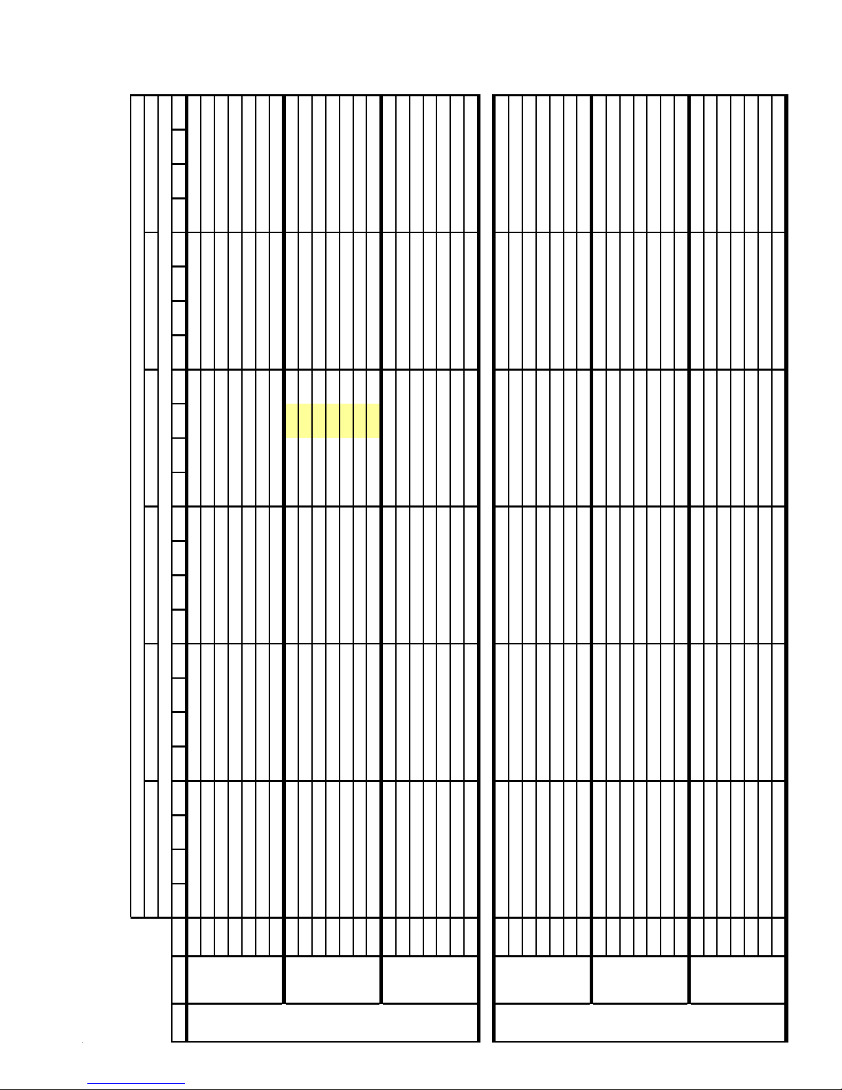
COOLING PERFORMANCE DATA
COOLING OPERATION
19.2 15.7 16.0 17.1 18.3 14.5 14.8 15.8 16.9
18.0
SSX140181A*
EXPANDED PERFORMANCE DATA
Outdoor Ambient Temperature
Entering Indoor Wet Bulb Temperature
65 75 85 95 105 115
MBh 18.318.719.921.317.818.219.520.817.417.819.020.317.017.418.519.816.116.517.618.814.915.316.317.4
S/T 0.890.830.680.510.920.860.700.520.940.880.720.541.000.910.740.561.000.950.770.581.000.960.780.58
Delta T222118152221191522211915232219152221181520201714
HI PR 226 243 246 252 255 274 278 284 290 312 316 323 330 355 360 368 372 400 405 41 4 416 448 454 464
AMPS 4.4 4.5 4.6 4.8 4.7 4.8 5.0 5.2 5.1 5.2 5.4 5.6 5.5 5.6 5.8 6.0 5.8 5.9 6.1 6.4 6.1 6.3 6.5 6.7
S/T 0.850.790.650.480.880.820.670.500.900.840.690.510.930.870.71 0.53 0.96 0.9 0 0.74 0.55 0.97 0.91 0.74 0.55
MBh 17.718.119.420.717.317.718.920.216.917.318.519.716.516.8
LO PR 116 120 131 139 119 123 135 143 124 127 139 148 127 131 143 152 12 9 133 146 155 133 13 7 149 159
Delta T232219152322191523221915232220 16 23 22 19 15 22 21 18 14
HI PR 223 240 244 249 253 272 275 282 287 309 313 320 327 352 357 365 36 8 396 401 410 412 443 450 459
AMPS 4.3 4.4 4.6 4.7 4.7 4.8 4.9 5.1 5.1 5.2 5.4 5.6 5.4 5.5 5.7 5.9 5.7 5.9 6.1 6.3 6.1 6.2 6.4 6.7
S/T 0.820.770.620.470.850.790.650.480.870.810.660.490.900.840.680.510.930.870.710.530.940.880.720.53
MBh 16.416.717.919.116.016.317.418.615.615.917.018.215.215.616.617.814.514.815.816.913.413.714.615.6
LO PR 115 119 129 138 118 122 133 142 122 126 138 147 126 130 141 151 128 132 144 154 131 135 148 157
Delta T232219162423201624232016242320162323201622211815
HI PR 221 238 241 247 250 269 273 279 284 306 310 317 324 348 353 361 364 392 397 40 6 408 439 445 455
AMPS 4.3 4.4 4.5 4.7 4.6 4.7 4.9 5.1 5.0 5.1 5.3 5.5 5.4 5.5 5.7 5.9 5.7 5.8 6.0 6.3 6.0 6.2 6.4 6.6
LO PR 114 117 128 136 117 121 132 140 121 125 136 145 124 128 140 149 12 7 131 143 152 130 13 4 146 156
MBh 18.618.919.821.218.118.519.420.717.718.118.920.217.317.618.419.716.416.717.518.715.215.516.217.3
S/T 0.930.900.810.660.960.930.840.680.990.950.860.701.000.980.890.721.001.000.920.751.001.000.930.75
Delta T242322192423221924232219232422192223221921212118
HI PR 226 243 246 252 255 274 278 284 290 312 316 323 330 355 360 368 372 400 405 41 4 416 448 454 464
AMPS 4.4 4.5 4.6 4.8 4.7 4.8 5.0 5.2 5.1 5.2 5.4 5.6 5.5 5.6 5.8 6.0 5.8 5.9 6.1 6.4 6.1 6.3 6.5 6.7
LO PR 116 120 131 139 119 123 135 143 124 127 139 148 127 131 143 152 12 9 133 146 155 133 13 7 149 159
Delta T242423202524232025242320252523202424232023232119
HI PR 223 240 244 249 253 272 275 282 287 309 313 320 327 352 357 365 368 396 401 41 0 412 443 450 459
AMPS 4.3 4.4 4.6 4.7 4.7 4.8 4.9 5.1 5.1 5.2 5.4 5.6 5.4 5.5 5.7 5.9 5.7 5.9 6.1 6.3 6.1 6.2 6.4 6.7
S/T 0.890.860.770.630.920.890.800.650.940.910.820.670.970.940.850.691.000.970.880.711.000.980.890.72
MBh 18.018.419.320.517.618.018.820.117.217.518.419.616.817.117.919.115.916.217.018.214.815.015.816.8
S/T 0.860.830.750.600.890.860.770.630.910.880.790.640.940.910.820.660.970.940.850.690.980.950.860.69
MBh 16.617.017.819.016.316.617.418.515.916.216.918.115.515.816.517.614.715.015.716.813.613.914.515.5
LO PR 115 119 129 138 118 122 133 142 122 126 138 147 126 130 141 151 12 8 132 144 154 131 13 5 148 157
Delta T252423202525232025252320252524202525232023232219
HI PR 221 238 241 247 250 269 273 279 284 306 310 317 324 348 353 361 364 392 397 40 6 408 439 445 455
AMPS 4.3 4.4 4.5 4.7 4.6 4.7 4.9 5.1 5.0 5.1 5.3 5.5 5.4 5.5 5.7 5.9 5.7 5.8 6.0 6.3 6.0 6.2 6.4 6.6
LO PR 114 117 128 136 117 121 132 140 121 125 136 145 124 128 140 149 12 7 131 143 152 130 13 4 146 156
676 KW 1.271.301.331.371.361.391.431.471.441.471.511.561.511.541.591.631.571.601.651.701.621.651.701.76
MODEL: SSX140181A* / CA*F3131B6A* + TXV, Design Subcooling @ ARI 95°F Conditions, 7° - 9°F @ the Serv. Vlv.
IDB*Airflow 596367715963677159636771596367715963677159636771
80 601 KW 1.261.291.321.361.351.381.421.461.431.461.501.551.501.531.57 1.62 1 .55 1.59 1.63 1.6 9 1.60 1.64 1.69 1.74
526 KW 1.251.281.311.351.341.371.411.451.421.451.491.531.491.521.561.611.541.571.621.671.591.621.671.73
676 KW 1.271.301.331.371.361.391.431.471.441.471.511.561.511.541.591.631.571.601.651.701.621.651.701.76
526 KW 1.251.281.311.351.341.371.411.451.421.451.491.531.491.521.561.611.541.571.621.671.591.621.671.73
* Entering Indoor Dry Bulb Temperature NOTE: Sh ad ed a rea i s A R I R at ing Con di t ion s
85 601 KW 1.261.291.321.361.351.381.421.461.431.461.501.551.501.531.571.621.551.591.631.691.601.641.691.74
9
Page 10
COOLING PERFORMANCE DATA
COOLING OPER AT ION
SSX140181B*
EXPANDED PERFORMANCE DATA
17 12 23 21 17 12 21 19 16 11
5.9 6.1 5 .9 6.1 6.2 6.5 6.3 6.4 6.6 6.8
348 363 344 371 391 408 380 409 432 451
17.6 18.9 15.0 15.4 16.7 17.9 13.9 14.3 15.5 16.6
0.56 0.36 0.86 0.77 0.58 0.37 0.87 0.78 0.59 0.38
21
16.3
0.74
Outdoor Ambient Temperature
Entering Indoor We t Bulb Temperature
141 150 127 136 148 158 132 140 153 163
2.40 2.46 2.38 2.42 2.48 2.54 2.44 2.48 2.54 2.61
5.7
329
129
2.34
17 12 22 20 17 12 21 19 16 11
6.0 6.3 6 .1 6.2 6.4 6.7 6.4 6.6 6.8 7.0
359 374 355 382 403 421 392 422 446 465
19.1 20.5 16.2 16.7 18.1 19.4 15.0 15.5 16.8 18.0
0.58 0.37 0.89 0.80 0.60 0.39 0.90 0.81 0.61 0.39
21
17.6
0.77
146 155 131 140 153 162 136 145 158 168
2.45 2.51 2.42 2.46 2.53 2.59 2.49 2.53 2.60 2.66
5.9
340
133
2.39
16 11 21 20 16 11 20 18 15 10
6.1 6.3 6 .1 6.3 6.5 6.7 6.5 6.6 6.8 7.1
362 378 359 386 407 425 396 426 450 470
19.6 21.1 16.7 17.2 18.6 20.0 15.5 16.0 17.3 18.5
0.61 0.39 0.94 0.84 0.63 0.41 0.94 0.84 0.64 0.41
20
18.1
0.81
147 157 133 141 154 164 137 146 159 170
2.46 2.53 2.44 2.48 2.54 2.61 2.50 2.55 2.61 2.68
5.9
343
135
2.40
65 75 85 95 105 115
S/T 0.67 0.56 0.38 - 0.69 0.58 0.40 - 0.71 0.59 0.41 - 0.73 0.61 0.42 - 0.76 0.63 0.44 - 0.76 0.64 0.44 -
MBh 16.7 17.3 18.9 - 16.3 16.9 18.5 - 15.9 16.5 18.1 - 15.5 16.1 17.6 - 14.7 15.3 16.7 - 13.7 14.2 15.5 -
MODEL: SSX140181*/CA*F3636*6C*
IDB*Airflow 59636771596367715963677159 63 67 715963677159636771
HI PR 208 224 237 - 234 252 266 - 266 286 302 - 303 326 344 - 341 367 387 - 377 405 428 -
AMPS 4.5 4.6 4.7 - 4.8 4.9 5.1 - 5.2 5.3 5.5 - 5.5 5.7 5.8 - 5.9 6.0 6.2 - 6.2 6.3 6.5 -
Delta T 19 17 13 - 20 17 13 - 20 17 13 - 20 17 13 - 20 17 13 - 18 16 12 -
525 KW 2.00 2.03 2.08 - 2.11 2.14 2.19 - 2.20 2.24 2.29 - 2.29 2.33 2.38 - 2.36 2.40 2.46 - 2.42 2.46 2.53 -
S/T 0.69 0.58 0.40 - 0.71 0.60 0.41 - 0.73 0.61 0.42 - 0.76 0.63 0.44 - 0.79 0.66 0.45 - 0.79 0.66 0.46 -
MBh 18.1 18.7 20.5 - 17.7 18.3 20.0 - 17.2 17.9 19.6 - 16.8 17.4 19.1 - 16.0 16.6 18.1 - 14.8 15.3 16.8 -
L O PR 104 1 1 1 1 21 - 110 117 128 - 1 15 122 133 - 1 20 128 140 - 12 6 134 146 - 130 139 15 1 -
Delta T 19 17 13 - 19 17 13 - 19 17 13 - 19 17 13 - 19 17 13 - 18 16 12 -
10
HI PR 215 231 244 - 241 260 274 - 274 295 312 - 312 336 355 - 351 378 399 - 388 418 441 -
AMPS 4.6 4.7 4.8 - 4.9 5.0 5.2 - 5.3 5.4 5.6 - 5.7 5.8 6.0 - 6.0 6.2 6.4 - 6.4 6.5 6.7 -
L O PR 108 1 1 4 1 25 - 114 121 132 - 1 18 126 137 - 1 24 132 144 - 13 0 138 151 - 134 143 15 6 -
70 600 KW 2.03 2.07 2.11 - 2.15 2.18 2.23 - 2.25 2.28 2.34 - 2.33 2.37 2.43 - 2.41 2.45 2.51 - 2.47 2.51 2.58 -
Delta T 18 16 12 - 19 16 12 - 19 16 12 - 19 16 12 - 18 16 12 - 17 15 11 -
HI PR 217 234 247 - 244 262 277 - 277 298 315 - 315 340 359 - 355 382 403 - 392 422 446 -
AMPS 4.6 4.7 4.9 - 5.0 5.1 5.2 - 5.4 5.5 5.7 - 5.7 5.9 6.0 - 6.1 6.2 6.4 - 6.4 6.6 6.8 -
L O PR 109 1 1 6 1 26 - 115 122 133 - 1 19 127 139 - 1 25 133 146 - 13 1 140 152 - 136 144 15 8 -
675 KW 2.05 2.08 2.12 - 2.16 2.19 2.25 - 2.26 2.30 2.35 - 2.35 2.39 2.45 - 2.42 2.46 2.53 - 2.49 2.53 2.59 -
S/T 0.72 0.60 0.42 - 0.75 0.63 0.43 - 0.77 0.64 0.44 - 0.79 0.66 0.46 - 0.82 0.69 0.48 - 0.83 0.69 0.48 -
MBh 18.6 19.3 21.1 - 18.2 18.8 20.7 - 17.8 18.4 20.2 - 17.3 18.0 19.7 - 16.5 17.1 18.7 - 15.2 15.8 17.3 -
S/T 0.76 0.68 0.51 0.33 0.78 0.70 0.53 0.34 0.80 0.72 0.54 0.35 0.83
MBh 17.0 17.5 18.9 20.3 16.6 17.1 18.5 19.8 16.2 16.7 18.0 19.4 15.8
Delta T22211712232117122321171223
525 KW 2.01 2.04 2.09 2.14 2 .12 2.15 2.20 2.26 2.22 2.25 2.31 2.37 2.30
HI PR 211 227 239 250 236 254 269 280 269 289 305 319 306
AMPS 4.5 4.6 4.7 4.9 4.8 4.9 5.1 5.3 5.2 5.4 5.5 5.7 5.6
S/T 0.78 0.70 0.53 0.34 0.81 0.73 0.55 0.35 0.83 0.75 0.56 0.36 0.86
MBh 18.4 18.9 20.5 22.0 18.0 18.5 20.0 21.5 17.5 18.0 19.5 21.0 17.1
L O PR 105 1 1 2 1 22 130 111 118 12 9 1 38 1 16 123 134 143 122
Delta T22201712222117122221171223
75 600 KW 2.05 2.08 2.12 2.17 2.16 2.19 2.25 2.30 2.26 2 .30 2.35 2.41 2.35
HI PR 217 234 247 257 244 262 277 289 277 298 315 328 316
AMPS 4.6 4.7 4.9 5.0 5.0 5.1 5.2 5.4 5.4 5.5 5.7 5.9 5.7
S/T 0.82 0.74 0.56 0.36 0.85 0.76 0.58 0.37 0.87 0.78 0.59 0.38 0.90
MBh 18.9 19.5 21.1 22.6 18.5 19.0 20.6 22.1 18.1 18.6 20.1 21.6 17.6
L O PR 109 1 1 6 1 26 134 115 122 13 3 1 42 1 19 127 139 148 125
Delta T21201611212016112120161122
675 KW 2.06 2.09 2.14 2.19 2 .17 2.21 2.26 2.31 2.27 2.31 2.37 2.43 2.36
HI PR 219 236 249 260 246 265 280 292 280 301 318 332 319
AMPS 4.7 4.8 4.9 5.1 5.0 5.1 5.3 5.5 5.4 5.5 5.7 5.9 5.8
L O PR 110 1 1 7 1 27 136 116 123 13 5 1 43 1 20 128 140 149 127
* Enter i n g Indoor Dry Bulb T e mperature NOTE: Shaded ar ea i s ACCA (T VA) conditions
Page 11
COOLING PERFORMANCE DATA
COOLING OPERATION
17 25 24 21 17 23 22 19 15
6.36.16.36.56.76.56.66.97.1
378 359 386 407 425 396 426 450 470
20.3 16.5 16.9 18.1 19.3 15.3 15.6 16.7 17.9
0.54 0.98 0.92 0.75 0.56 0.99 0.93 0.75 0.56
21
19.0
0.72
157 133 141 154 164 137 146 159 170
2.53 2.44 2.48 2.54 2.61 2.50 2.55 2.61 2.68
6.1
362
147
2.46
SSX140181B*
E XPANDED PE RFORMANCE DATA
Outdoor Ambient Temperature
Entering Indoor Wet Bulb Temperature
65 75 85 95 105 115
S/T 0.830.780.630.470.860.810.660.490.880.830.670.500.91 0.85 0.69 0.520.940.890.720.540.950.890.730.54
MBh 17.3 17.6 18.9 20.2 16.9 17.2 18.4 19.7 16.5 16.8 18.0 19.2 16.1 16.4 17.5 18.7 15.3 15.6 16.7 17.8 14.1 14.4 15.4 16.5
Delta T25242117252421172524211726 25 21 172524211724232016
HI PR 213 229 242 252 239 257 271 283 271 292 308 322 309 333 351 366 348 374 395 412 384 414 437 455
AMPS 4.5 4.6 4.8 4.9 4.9 5.0 5.1 5.3 5.3 5.4 5.6 5.8 5.6 5.8 5.9 6.2 6.0 6.1 6.3 6.5 6.3 6.5 6.7 6.9
S/T 0.860.810.660.490.890.840.680.510.910.860.700.520.94 0.88
MBh 18.719.120.421.818.318.720.021.317.818.219.520.817.4 17.8
L O PR 106 11 3 1 24 132 112 120 13 1 1 39 1 1 7 1 24 136 145 123 131 143 152 1 29 137 149 159 133 142 155 165
Delta T25242116252421172524211725 24
HI PR 219 236 249 260 246 265 280 292 280 301 318 332 319 343
AMPS 4.7 4.8 4.9 5.1 5.0 5.1 5.3 5.5 5.4 5.5 5.7 5.9 5.8 5.9
S/T 0.900.850.690.510.930.880.710.530.960.900.730.551.00 0.93 0.75 0.561.000.960.780.591.000.970.790.59
MBh 19.3 19.7 21.0 22.5 18.8 19.2 20.5 22.0 18.4 18.8 20.1 21.4 17.9 18.3 19.6 20.9 17.0 17.4 18.6 19.9 15.8 16.1 17.2 18.4
LO PR 110 117 127 136 116 123 135 143 120 128 140 149 127 135
Delta T24232016242320162423201624 23 20 162323201621211915
HI PR 221 238 252 263 249 267 282 295 283 304 321 335 322 346 366 382 362 390 412 429 400 431 455 474
AMPS 4.7 4.8 4.9 5.1 5.1 5.2 5.3 5.5 5.5 5.6 5.8 6.0 5.8 6.0 6.2 6.4 6.2 6.3 6.5 6.8 6.5 6.7 6.9 7.2
L O PR 111 11 8 1 29 137 117 125 13 6 1 45 1 2 2 1 29 141 151 128 136 148 158 1 34 143 156 166 139 147 161 171
S/T 0.870.840.760.610.900.870.780.640.920.890.800.650.95 0.92 0.83 0.670.990.950.860.701.000.960.870.71
MBh 17.6 17.9 18.8 20.0 17.2 17.5 18.3 19.5 16.8 17.1 17.9 19.1 16.3 16.7 17.4 18.6 15.5 15.8 16.6 17.7 14.4 14.7 15.4 16.4
Delta T27262522272725222727252227 27 25 222726252225252320
HI PR 215 231 244 255 241 259 274 286 274 295 312 325 312 336 355 370 351 378 399 416 388 418 441 460
AMPS 4.6 4.7 4.8 5.0 4.9 5.0 5.2 5.4 5.3 5.4 5.6 5.8 5.7 5.8 6.0 6.2 6.0 6.2 6.4 6.6 6.4 6.5 6.7 7.0
S/T 0.900.870.790.640.930.900.810.660.960.920.830.680.99 0.95 0.86 0.701.000.990.890.731.001.000.900.73
MBh 19.0 19.4 20.3 21.7 18.6 19.0 19.9 21.2 18.2 18.5 19.4 20.7 17.7 18.1 18.9 20.2 16.8 17.1 18.0 19.2 15.6 15.9 16.6 17.7
L O PR 108 11 4 1 25 133 114 121 13 2 1 40 1 1 8 1 26 137 146 124 132 144 153 1 30 138 151 161 134 143 156 166
Delta T26262421272625212726252127 26 25 222626252124242320
HI PR 221 238 252 263 249 267 282 295 283 304 321 335 322 346 366 382 362 390 412 429 400 431 455 474
AMPS 4.7 4.8 4.9 5.1 5.1 5.2 5.3 5.5 5.5 5.6 5.8 6.0 5.8 6.0 6.2 6.4 6.2 6.3 6.5 6.8 6.5 6.7 6.9 7.2
S/T 0.950.910.820.670.980.950.850.691.000.970.870.711.00 1.00 0.90 0.731.001.000.940.761.001.000.940.77
MBh 19.6 20.0 20.9 22.3 19.2 19.5 20.4 21.8 18.7 19.1 20.0 21.3 18.2 18.6 19.5 20.8 17.3 17.7 18.5 19.7 16.1 16.4 17.1 18.3
L O PR 111 11 8 1 29 137 117 125 13 6 1 45 1 2 2 1 29 141 151 128 136 148 158 1 34 143 156 166 139 147 161 171
Delta T25252320262524212525242125 25 24 212424242022222219
HI PR 224 241 254 265 251 270 285 298 285 307 324 338 325 350 369 385 366 394 416 434 404 435 459 479
AMPS 4.7 4.8 5.0 5.2 5.1 5.2 5.4 5.6 5.5 5.6 5.8 6.0 5.9 6.0 6.2 6.4 6.2 6.4 6.6 6.8 6.6 6.8 7.0 7.2
L O PR 112 11 9 1 30 138 118 126 13 7 1 46 1 2 3 1 31 143 152 129 137 150 160 1 35 144 157 167 140 149 163 173
525 KW 2.02 2.05 2.10 2.15 2.13 2.17 2.22 2.27 2.23 2.27 2.32 2.38 2.32 2.36 2.41 2.48 2.39 2.43 2.49 2.56 2.45 2.50 2.56 2.63
MODEL: SSX140181*/CA*F3636*6C*
IDB*Airflow 59636771596367715963677159 63 67 715963677159636771
675 KW 2.07 2.10 2.15 2.20 2.19 2.22 2.27 2.33 2.29 2.32 2.38 2.44 2.38 2.42 2.48 2.54 2.45 2.50 2.56 2.63 2.52 2.56 2.63 2.70
80 600 KW 2.06 2.09 2.14 2.19 2.17 2.21 2.26 2.31 2.27 2.31 2.37 2.43 2.36 2.40
525 KW 2.03 2.06 2.11 2.16 2.15 2.18 2.23 2.29 2.24 2.28 2.34 2.40 2.33 2.37 2.43 2.49 2.41 2.45 2.51 2.57 2.47 2.51 2.58 2.65
85 600 KW 2.07 2.10 2.15 2.20 2.19 2.22 2.27 2.33 2.29 2.32 2.38 2.44 2.38 2.42 2.48 2.54 2.45 2.50 2.56 2.63 2.52 2.56 2.63 2.70
675 KW 2.08 2.11 2.16 2.21 2.20 2.23 2.29 2.34 2.30 2.34 2.40 2.46 2.39 2.43 2.49 2.56 2.47 2.51 2.58 2.64 2.54 2.58 2.65 2.72
* Entering Indoor Dry Bulb Temperature NOTE: Shaded ar e a i s AHRI R a ti ng Conditi ons
11
Page 12
COOLING PERFORMANCE DATA
COOLING OP ERATION
SSX140241A*
EXPANDED PERFORMANCE DATA
7.5 7.8 7.6 7.8 8.0 8.4 8.0 8.3 8.5 8.9
147 157 133 137 150 160 136 141 154 164
24.1 25.8 20.5 21.1 22.9 24.5 19.0 19.6 21.2 22.7
7.3
135
22.2
Outdoor Ambient Temperature
Entering Indoor Wet Bulb Temperature
7.4 7.7 7.5 7.6 7.9 8.2 7.9 8.1 8.4 8.7
7.2
144 153 130 135 147 156 134 138 151 160
132
65 75 85 95 105 115
S/T 0.73 0.61 0.42 - 0.76 0.63 0.44 - 0.78 0.65 0.45 - 0.80 0.67 0.46 - 0.83 0.70 0.48 - 0.84 0.70 0.49 -
MBh 23.5 24.4 26.7 - 23.0 23.8 26.1 - 22.4 23.2 25.5 - 21.9 22.7 24.8 - 20.8 21.5 23.6 - 19.3 20.0 21.9 -
MODEL: SSX140241A* / CA*F3636B6A* / .057 Orifice, Design Superheat @ ARI 95°F Conditions, 5° ±2°F @ the Serv. Vlv.
IDB*Airflow 59636771596367715963677159 63 67715963677159636771
HI PR 242 260 264 - 273 294 298 - 311 334 339 - 354 381 386 - 398 428 434 - 446 480 486 -
AMPS 5.7 5.8 6.0 - 6.1 6.3 6.5 - 6.7 6.8 7.1 - 7.1 7.3 7.5 - 7.6 7.8 8.0 - 8.0 8.3 8.5 -
Delta T 18 15 12 - 18 15 12 - 18 15 12 - 18 16 12 - 18 15 12 - 17 14 11 -
900 KW 1.63 1.66 1.71 - 1.75 1.78 1.84 - 1.85 1.89 1.95 - 1.94 1.98 2.04 - 2.02 2.06 2.13 - 2.09 2.13 2.20 -
S/T 0.70 0.58 0.40 - 0.72 0.60 0.42 - 0.74 0.62 0.43 - 0.77 0.64 0.44 - 0.80 0.66 0.46 - 0.80 0.67 0.46 -
MBh 22.8 23.7 25.9 - 22.3 23.1 25.3 - 21.8 22.6 24.7 - 21.2 22.0 24.1 - 20.2 20.9 22.9 - 18.7 19.4 21.2 -
LO PR 119 123 134 - 123 127 138 - 127 131 143 - 130 135 147 - 133 137 150 - 136 141 154 -
Delta T 18 16 12 - 19 16 12 - 19 16 12 - 19 16 12 - 18 16 12 - 17 15 11 -
12
HI PR 239 257 261 - 271 291 295 - 308 331 336 - 350 377 382 - 394 424 430 - 442 475 482 -
AMPS 5.6 5.7 5.9 - 6.1 6.2 6.4 - 6.6 6.8 7.0 - 7.1 7.2 7.5 - 7.5 7.7 8.0 - 8.0 8.2 8.5 -
LO PR 118 122 133 - 122 126 137 - 126 130 142 - 129 133 146 - 132 136 148 - 135 139 152 -
70 800 KW 1.62 1.65 1.70 - 1.74 1.77 1.82 - 1.84 1.87 1.93 - 1.93 1.97 2.03 - 2.00 2. 05 2.11 - 2.07 2.11 2.18 -
HI PR 237 255 258 - 268 288 292 - 305 328 332 - 347 373 378 - 390 420 426 - 437 470 477 -
AMPS 5.6 5.7 5.9 - 6.0 6.2 6.4 - 6.5 6.7 6.9 - 7.0 7.2 7.4 - 7.5 7.6 7.9 - 7.9 8.1 8.4 -
Delta T 19 16 12 - 19 16 12 - 19 16 12 - 19 16 12 - 19 16 12 - 18 15 12 -
700 KW 1.61 1.64 1.69 - 1.72 1.76 1.81 - 1.82 1.86 1.92 - 1.91 1.95 2.01 - 1.99 2.03 2.09 - 2.05 2.10 2.16 -
LO PR 117 121 132 - 120 124 136 - 125 129 140 - 128 132 144 - 130 135 147 - 134 138 151 -
S/T 0.67 0.56 0.39 - 0.70 0.58 0.40 - 0.72 0.60 0.41 - 0.74 0.62 0.43 - 0.77 0.64 0.44 - 0.77 0.65 0.45 -
MBh 21.1 21.8 23.9 - 20.6 21.3 23.4 - 20.1 20.8 22.8 - 19.6 20.3 22.3 - 18.6 19.3 21.1 - 17.3 17.9 19.6 -
MBh 23.9 24.6 26.7 28.6 23.4 24. 1 26.0 27.9 22.8 23.5 25.4 27.3 22.2 22.9 24.8 26.6 21.1 21.8 23.6 25.3 19.6 20.2 21.8 23.4
S/T 0.83 0.74 0.56 0.36 0.86 0.77 0.58 0.38 0.88 0.79 0.60 0.39 0.91 0.82 0.62 0.40 0.95 0.85 0.64 0.41 0.96 0.85 0.65 0.42
Delta T20191511211916112119161121 19 16 11 20 19 15 11 19 18 14 10
900 KW 1.63 1.66 1.71 1.76 1.75 1.78 1.84 1.89 1.85 1.89 1.95 2.01 1.94 1.98 2.04 2.11 2.02 2.06 2.13 2.19 2.09 2.13 2.20 2.27
HI PR 242 260 264 269 273 294 298 305 311 334 339 346 354 381 386 394 398 428 434 444 446 480 486 497
AMPS 5.7 5.8 6.0 6. 2 6.1 6.3 6.5 6.7 6.7 6.8 7.1 7.3 7.1
LO PR 119 123 134 143 123 127 138 147 127 131 143 152 130
Delta T21201611212016112120161122 20 16 11 21 20 16 11 20 18 15 10
75 800 KW 1.62 1.65 1.70 1.75 1.74 1.77 1.82 1.88 1.84 1.87 1.93 1.99 1.93 1.97 2.03 2.09 2.00 2.05 2.11 2.18 2.07 2.11 2.18 2.25
HI PR 239 257 261 267 271 291 295 302 308 331 336 343 350 377 382 391 394 424 430 439 442 475 482 492
AMPS 5.6 5.7 5.9 6. 2 6.1 6.2 6.4 6.7 6.6 6.8 7.0 7.3 7.1 7.2 7.5 7.8 7.5 7.7 8.0 8.3 8.0 8.2 8.5 8.8
S/T 0.79 0.71 0.54 0.35 0.82 0.74 0.56 0.36 0.84 0.75 0.57 0.37 0.87 0.78 0.59 0.38 0.90 0.81 0.61 0.39 0.91 0.82 0.62 0.40
MBh 23.2 23.9 25.9 27.8 22.7 23. 4 25.3 27.1 22.1 22.8 24.7 26.5 21.6
LO PR 118 122 133 142 122 126 137 146 126 130 142 151 129 133 146 155 132 136 148 158 135 139 152 162
MBh 21.4 22.1 23.9 25.6 20.9 21. 6 23.3 25.0 20.4 21.0 22.8 24.4 19.9 20.5 22.2 23.8 18.9 19.5 21.1 22.7 17.5 18.1 19.6 21.0
S/T 0.77 0.68 0.52 0.33 0.79 0.71 0.54 0.35 0.81 0.73 0.55 0.35 0.84 0.75 0.57 0.37 0.87 0.78 0.59 0.38 0.88 0.79 0.59 0.38
Delta T22201611222016112220161122 20 17 11 22 20 16 11 20 19 15 11
700 KW 1.61 1.64 1.69 1.74 1.72 1.76 1.81 1.86 1.82 1.86 1.92 1.98 1.91 1.95 2.01 2.07 1.99 2.03 2.09 2.16 2.05 2.10 2.16 2.23
HI PR 237 255 258 264 268 288 292 298 305 328 332 339 347 373 378 387 390 420 426 435 437 470 477 487
AMPS 5.6 5.7 5.9 6. 1 6.0 6.2 6.4 6.6 6.5 6.7 6.9 7.2 7.0
LO PR 117 121 132 140 120 124 136 145 125 129 140 149 128
* Ent ering Indoor Dry Bulb Temperature NOTE: Shaded area is ACCA (TVA) conditions
Page 13

COOLING PERFORMANCE DATA
COOLING OPERATION
SSX140241A*
EXPANDED PERFORMANCE DATA
Outdoor Ambient Temperature
Entering Indoor Wet Bulb Temperature
65 75 85 95 105 115
MBh 24.3 24.9 26.6 28.4 23.8 24.3 26.0 27.7 23.2 23.7 25.3 27.1 22.6 23.1 24.7 26.4 21.5 22.0 23.5 25.1 19.9 20.4 21.8 23.3
S/T 0.910.860.700.520.950.890.720.540.970.910.740.551.00 0.94 0.760.571.001.000.790.591.001.000.800.60
Delta T23221915232219152322191523 22 19152222191520211814
HI PR 242 260 264 269 273 294 298 305 311 334 339 346 354 381 386 394 398 428 434 444 446 480 486 497
AMPS 5.7 5.8 6.0 6.2 6.1 6.3 6.5 6.7 6.7 6.8 7.1 7.3 7.1 7.3 7.5 7.8 7.6 7.8 8.0 8.4 8.0 8.3 8.5 8.9
LO PR 119 123 134 143 123 127 138 147 127 131 143 152 130 135 147 157 133 137 150 160 136 141 154 164
Delta T24232016242320162423201624 23 20 16 24 23 20 16 22 21 19 15
HI PR 239 257 261 267 271 291 295 302 308 331 336 343 350 377 382 391 394 424 430 439 442 475 482 492
AMPS 5.6 5.7 5.9 6.2 6.1 6.2 6.4 6.7 6.6 6.8 7.0 7.3 7.1 7.2 7.5 7.8 7.5 7.7 8.0 8.3 8.0 8.2 8.5 8.8
S/T 0.87 0.82 0.66 0.50 0.90 0.85 0.69 0.51 0.93 0.87 0.71 0.53 0.96 0.90 0.73 0.54 0.99 0.93 0.76 0.57 1.00 0.94 0.76 0.57
MBh 23.6 24.1 25.8 27.6 23.1 23.6 25.2 26.9 22.5 23.0 24.6 26.3 22.0 22.5 24.0 25.7 20.9 21.3 22.8 24.4 19.3 19.8 21.1 22.6
LO PR 118 122 133 142 122 126 137 146 126 130 142 151 129 133 146 155 132 136 148 158 135 139 152 162
MBh 21.8 22.3 23.8 25.5 21.3 21.8 23.3 24.9 20.8 21.3 22.7 24.3 20.3 20.7 22.2 23.7 19.3 19.7 21.0 22.5 17.9 18.2 19.5 20.8
S/T 0.840.790.640.480.870.820.660.500.890.840.680.510.92 0.86 0.700.530.960.900.730.550.960.900.740.55
Delta T24232016242320162423201625 24 20162423201623221915
HI PR 237 255 258 264 268 288 292 298 305 328 332 339 347 373 378 387 390 420 426 435 437 470 477 487
AMPS 5.6 5.7 5.9 6.1 6.0 6.2 6.4 6.6 6.5 6.7 6.9 7.2 7.0 7.2 7.4 7.7 7.5 7.6 7.9 8.2 7.9 8.1 8.4 8.7
LO PR 117 121 132 140 120 124 136 145 125 129 140 149 128 132 144 153 130 135 147 156 134 138 151 160
MBh 24.8 25.2 26.4 28.2 24.2 24.7 25.8 27.6 23.6 24.1 25.2 26.9 23.0 23.5 24.6 26.2 21.9 22.3 23.4 24.9 20.3 20.7 21.6 23.1
S/T 0.960.920.830.680.990.960.860.701.000.980.890.721.00 1.00 0.910.741.001.000.950.771.001.000.960.78
Delta T24242319252423202424232024 24 23202223232021212118
HI PR 242 260 264 269 273 294 298 305 311 334 339 346 354 381 386 394 398 428 434 444 446 480 486 497
AMPS 5.7 5.8 6.0 6.2 6.1 6.3 6.5 6.7 6.7 6.8 7.1 7.3 7.1 7.3 7.5 7.8 7.6 7.8 8.0 8.4 8.0 8.3 8.5 8.9
LO PR 119 123 134 143 123 127 138 147 127 131 143 152 130 135 147 157 133 137 150 160 136 141 154 164
MBh 24.0 24.5 25.7 27.4 23.5 23.9 25.1 26.8 22.9 23.4 24.5 26.1 22.4 22.8 23.9 25.5 21.2 21.7 22.7 24.2 19.7 20.1 21.0 22.4
S/T 0.910.880.790.640.950.910.820.670.970.940.840.691.00 0.97 0.870.711.001.000.900.731.001.000.910.74
Delta T25252320262524212625242126 25 24212425242023232219
HI PR 239 257 261 267 271 291 295 302 308 331 336 343 350 377 382 391 394 424 430 439 442 475 482 492
AMPS 5.6 5.7 5.9 6.2 6.1 6.2 6.4 6.7 6.6 6.8 7.0 7.3 7.1 7.2 7.5 7.8 7.5 7.7 8.0 8.3 8.0 8.2 8.5 8.8
LO PR 118 122 133 142 122 126 137 146 126 130 142 151 129 133 146 155 132 136 148 158 135 139 152 162
MBh 22.2 22.6 23.7 25.3 21.7 22.1 23.1 24.7 21.2 21.6 22.6 24.1 20.6 21.0 22.0 23.5 19.6 20.0 20.9 22.3 18.2 18.5 19.4 20.7
S/T 0.880.850.770.620.910.880.790.640.940.900.810.660.97 0.93 0.840.681.000.970.870.711.000.980.880.71
Delta T26252421262624212626242126 26 24212625242124242219
HI PR 237 255 258 264 268 288 292 298 305 328 332 339 347 373 378 387 390 420 426 435 437 470 477 487
AMPS 5.6 5.7 5.9 6.1 6.0 6.2 6.4 6.6 6.5 6.7 6.9 7.2 7.0 7.2 7.4 7.7 7.5 7.6 7.9 8.2 7.9 8.1 8.4 8.7
LO PR 117 121 132 140 120 124 136 145 125 129 140 149 128 132 144 153 130 135 147 156 134 138 151 160
900 KW 1.63 1.66 1.71 1.76 1.75 1.78 1.84 1.89 1.85 1.89 1.95 2.01 1.94 1.98 2.04 2.11 2.02 2.06 2.13 2.19 2.09 2.13 2.20 2.27
MODEL: SSX140241A* / CA*F3636B6A* / .057 Orifice, Design Superheat @ ARI 95°F Conditions, 5° ±2°F @ the Serv. Vlv.
IDB*Airflow 59636771596367715963677159 63 67715963677159636771
80 800 KW 1.62 1.65 1.70 1.75 1.74 1.77 1.82 1.88 1.84 1.87 1.93 1.99 1.93 1.97 2.03 2.09 2.00 2.05 2.11 2.18 2.07 2.11 2.18 2.25
700 KW 1.61 1.64 1.69 1.74 1.72 1.76 1.81 1.86 1.82 1.86 1.92 1.98 1.91 1.95 2.01 2.07 1.99 2.03 2.09 2.16 2.05 2.10 2.16 2.23
900 KW 1.63 1.66 1.71 1.76 1.75 1.78 1.84 1.89 1.85 1.89 1.95 2.01 1.94 1.98 2.04 2.11 2.02 2.06 2.13 2.19 2.09 2.13 2.20 2.27
700 KW 1.61 1.64 1.69 1.74 1.72 1.76 1.81 1.86 1.82 1.86 1.92 1.98 1.91 1.95 2.01 2.07 1.99 2.03 2.09 2.16 2.05 2.10 2.16 2.23
* E nt ering Indoor Dry Bulb Temperature NOT E: Shaded area is ARI Rating Conditions
85 800 KW 1.62 1.65 1.70 1.75 1.74 1.77 1.82 1.88 1.84 1.87 1.93 1.99 1.93 1.97 2.03 2.09 2.00 2.05 2.11 2.18 2.07 2.11 2.18 2.25
13
Page 14

COOLING PERFORMANCE DATA
COO LING OPERATION
SSX140241B*
EXPANDED PERFORMANCE DATA
18 12 23 21 17 12 22 20 16 11
7.8 8.1 7.9 8 .1 8.3 8.7 8.3 8 .5 8.8 9.2
388 405 384 414 437 456 425 457 483 503
2.03 2.10 2.01 2.05 2.12 2.19 2.08 2.12 2.19 2.26
1.97
142 151 128 136 149 158 133 141 154 164
7.6
368
130
24.6 26.4 21.0 21.6 23.4 25.1 19.5 20.0 21.7 23.3
0.55 0.35 0.84 0.75 0.57 0.36 0.84 0.75 0.57 0.37
22
22.8
0.72
Outdoor Ambient Temperature
Entering Indoor We t Bulb Temperature
17 12 23 21 17 12 21 20 16 11
7.9 8.2 8.0 8 .2 8.4 8.8 8.4 8 .7 8.9 9.3
393 410 389 419 442 462 430 463 489 510
2.05 2.12 2.03 2.07 2.14 2.21 2.10 2.14 2.21 2.29
1.99
144 153 130 138 151 161 134 143 156 166
7.7
372
132
24.9 26.7 21.2 21.8 23.6 25.4 19.6 20.2 21.9 23.5
0.55 0.35 0.84 0.76 0.57 0.37 0.85 0.76 0.58 0.37
21
23.0
0.73
15 11 20 19 15 10 19 17 14 10
8.1 8.4 8.1 8 .3 8.6 8.9 8.6 8 .8 9.1 9.5
401 418 397 427 451 471 439 472 499 520
2.09 2.16 2.06 2.11 2.17 2.25 2.13 2.18 2.25 2.32
2.02
147 156 132 141 154 164 137 146 159 169
7.8
380
134
25.8 27.6 22.0 22.6 24.5 26.3 20.3 20.9 22.7 24.3
0.59 0.38 0.90 0.80 0.61 0.39 0.90 0.81 0.61 0.39
19
23.8
0.77
65 75 85 95 105 115
S/T 0.65 0.54 0.37 - 0 .67 0.56 0.39 - 0.69 0.57 0.40 - 0.71 0.59 0.41 - 0.74 0.61 0.43 - 0.74 0.62 0.43 -
MBh 23.4 24.2 26.5 - 22.8 23.7 25.9 - 22.3 23.1 25.3 - 21.7 22.5 24.7 - 20.7 21.4 23.5 - 19.1 19.8 21.7 -
MODEL: SSX140241*/CA*F3636*6C*
IDB*Airflow 59636771596367715963677159 63 67 715963677159636771
Delta T201713 - 201713 - 201713 - 20 18 13 - 201713 - 191612 -
700 KW 1.60 1.63 1.68 - 1.72 1.75 1.81 - 1.82 1.86 1.92 - 1.91 1.95 2.02 - 1.99 2.03 2.10 - 2.06 2.10 2.17 -
HI PR 233 250 264 - 261 281 297 - 297 320 337 - 338 364 384 - 380 409 432 - 420 452 478 -
AMPS 5.8 6.0 6.2 - 6.3 6.5 6.7 - 6.9 7.0 7.3 - 7.3 7.5 7.8 - 7.8 8.0 8.3 - 8.3 8.5 8.8 -
S/T 0.65 0.54 0.38 - 0 .68 0.56 0.39 - 0.69 0.58 0.40 - 0.72 0.60 0.41 - 0.74 0.62 0.43 - 0.75 0.63 0.43 -
MBh 23.6 24.5 26.8 - 23.1 23.9 26.2 - 22.5 23.3 25.6 - 22.0 22.8 24.9 - 20.9 21.6 23.7 - 19.3 20.0 21.9 -
L O PR 105 112 122 - 111 118 129 - 115 123 13 4 - 121 129 141 - 127 1 35 1 4 7 - 131 14 0 152 -
Delta T201713 - 201713 - 201713 - 20 17 13 - 201713 - 181612 -
14
HI PR 236 254 268 - 265 285 301 - 301 324 342 - 343 369 389 - 385 415 438 - 426 458 484 -
AMPS 5.9 6.1 6.2 - 6.4 6.5 6.8 - 6.9 7.1 7.3 - 7.4 7.6 7.9 - 7.9 8.1 8.4 - 8.4 8.6 8.9 -
L O PR 106 113 123 - 112 119 130 - 117 124 13 6 - 123 130 142 - 128 1 37 1 4 9 - 133 14 1 154 -
70 725 KW 1.62 1.65 1.70 - 1 .74 1.77 1.83 - 1.84 1.88 1.94 - 1.93 1.97 2.04 - 2.01 2.06 2.12 - 2.08 2.13 2.19 -
Delta T171511 - 181512 - 181512 - 18 15 12 - 171511 - 161411 -
900 KW 1.64 1.67 1.72 - 1.76 1.80 1.85 - 1.87 1.91 1.97 - 1.96 2.01 2.07 - 2.04 2.09 2.16 - 2.11 2.16 2.23 -
HI PR 240 259 273 - 270 290 307 - 307 330 349 - 349 376 397 - 393 423 447 - 434 467 494 -
AMPS 6.0 6.2 6.4 - 6.5 6.7 6.9 - 7.1 7.2 7.5 - 7.6 7.7 8.0 - 8.0 8.2 8.5 - 8.5 8.7 9.0 -
L O PR 108 115 126 - 115 122 133 - 119 127 13 8 - 125 133 145 - 131 1 39 1 5 2 - 136 14 4 157 -
S/T 0.69 0.58 0.40 - 0 .72 0.60 0.42 - 0.74 0.62 0.43 - 0.76 0.64 0.44 - 0.79 0.66 0.46 - 0.80 0.66 0.46 -
MBh 24.4 25.3 27.7 - 23.9 24.7 27.1 - 23.3 24.1 26.5 - 22.7 23.6 25.8 - 21.6 22.4 24.5 - 20.0 20.7 22.7 -
S/T 0.73 0.66 0.50 0.32 0.76 0.68 0.51 0.33 0.78 0.70 0.53 0.34 0.81
MBh 23.8 24.5 26.5 28.4 23.2 23.9 25.9 27.8 22.7 23.3 25.3 27.1 22.1
Delta T23211712232117122321181223
700 KW 1.61 1.64 1.69 1.75 1.73 1.77 1.82 1.88 1.84 1.87 1.93 2.00 1.93
AMPS5.96.06.26.56.46.56.77.06.97.17.37.67.4
HI PR 235 253 267 279 264 284 300 313 300 323 341 356 342
S/T 0.74 0.66 0.50 0.32 0.77 0.69 0.52 0.33 0.79 0.70 0.53 0.34 0.81
MBh 24.0 24.7 26.8 28.7 23.4 24.1 26.1 28.0 22.9 23.6 25.5 27.4 22.3
L O PR 106 113 123 13 1 112 119 130 139 116 124 135 1 44 1 2 2
Delta T23211712232117122321171223
75 725 KW 1.63 1.66 1.71 1.77 1.75 1.79 1.84 1.90 1.86 1.89 1.95 2.02 1.95
HI PR 238 256 271 282 267 288 304 317 304 327 345 360 346
AMPS6.06.16.36.56.46.66.87.17.07.27.47.77.5
S/T 0.79 0.70 0.53 0.34 0.82 0.73 0.55 0.36 0.84 0.75 0.57 0.36 0.86
MBh 24.8 25.6 27.7 29.7 24.3 25.0 27.0 29.0 23.7 24.4 26.4 28.3 23.1
L O PR 107 114 125 13 3 113 121 132 140 118 125 137 1 46 1 2 4
Delta T20181510201915112019151120
900 KW 1.65 1.69 1.74 1.79 1.78 1.81 1.87 1.93 1.88 1.92 1.99 2.05 1.98
HI PR 243 261 276 288 273 293 310 323 310 334 352 367 353
AMPS6.16.26.46.76.66.76.97.27.17.37.57.87.6
L O PR 110 117 127 13 5 116 123 134 143 120 128 140 1 49 1 2 6
* Entering Indoor Dry Bulb Temperature NOTE: Shaded area is ACCA (TVA) conditions
Page 15

COOLING PERFORMANCE DATA
COOLING OPERATION
17 25 24 21 17 24 23 20 16
8.38.08.28.58.88.58.79.09.4
414 393 423 447 466 435 468 494 515
26.5 21.6 22.1 23.6 25.2 20.0 20.4 21.8 23.3
0.51 0.93 0.87 0.71 0.53 0.93 0.88 0.71 0.53
21
24.8
0.68
155 131 139 152 162 136 144 158 168
2.14 2.05 2.09 2.16 2.23 2.11 2.16 2.23 2.31
8.0
397
145
2.07
SSX140241B*
EXPANDED PERFORMANCE DATA
Outdoor Ambient Temperature
Entering Indoor Wet Bulb Temperature
65 75 85 95 105 115
MBh 24.224.726.428.223.624.125.827.623.123.625.226.922.5 23.0 24.6 26.321.421.823.324.919.820.221.623.1
S/T 0.81 0.76 0.61 0.46 0.83 0.78 0.64 0.48 0.86 0.80 0.65 0.49 0.88 0.83 0.67 0.50 0.92 0.86 0.70 0.52 0.92 0.87 0.71 0.53
Delta T26252117262522172625221726 25 22 172625211724232016
HI PR 237 255 270 281 266 287 303 316 303 326 344 359 345 371 392 409 388 418 441 460 429 462 487 508
AMPS 5.9 6.1 6.3 6.5 6.4 6 .6 6.8 7.1 7.0 7.2 7.4 7 .7 7.5 7.6 7.9 8.2 7.9 8.1 8.4 8.7 8.4 8.6 8.9 9.3
S/T 0.81 0.76 0.62 0.46 0.84 0.79 0.64 0.48 0.86 0.81 0.66 0.49 0.89 0.84
MBh 24.4 25.0 26.7 28.5 23.9 24.4 26.1 27.8 23.3 23.8 25.4 27.2 22.7 23.2
LO PR 10 7 114 124 132 113 120 131 140 118 125 137 14 5 123 131 143 1 53 12 9 138 150 160 134 142 155 166
Delta T25242117262421172624211726 25
HI PR 241 259 273 285 270 290 307 320 307 330 349 364 350 376
AMPS6.06.26.46.66.56.76.97.17.17.27.57.87.6 7.7
S/T 0.86 0.81 0.66 0.49 0.90 0.84 0.68 0.51 0.92 0.86 0.70 0.52 0.95 0.89 0.72 0.54 1.00 0.92 0.75 0.56 1.00 0.93 0.76 0.57
MBh 25.325.827.629.524.725.227.028.824.124.626.328.123.5 24.0 25.7 27.522.322.824.426.120.721.222.624.2
LO PR 10 8 115 126 134 115 122 133 142 119 127 138 14 7 125 133
Delta T22211915232219152322191523 22 19 152322191521201714
HI PR 245 264 279 291 275 296 313 326 313 337 356 371 357 384 405 423 401 432 456 476 443 477 504 525
AMPS 6.1 6.3 6.5 6.7 6.6 6 .8 7.0 7.3 7.2 7.4 7.6 7 .9 7.7 7.9 8.1 8.5 8.2 8.4 8.7 9.0 8.7 8.9 9.2 9.5
LO PR 11 1 118 128 137 117 124 136 145 121 129 141 15 0 128 136 148 1 58 13 4 142 155 165 138 147 161 171
MBh 24.625.126.328.024.024.525.727.423.523.925.126.722.9 23.3 24.4 26.121.722.223.224.820.120.521.522.9
S/T 0.84 0.81 0.73 0.60 0.87 0.84 0.76 0.62 0.90 0.87 0.78 0.63 0.93 0.89 0.81 0.65 0.96 0.93 0.84 0.68 0.97 0.93 0.84 0.68
Delta T27272522282726222827262228 27 26 222727262226252421
HI PR 240 258 272 284 269 290 306 319 306 329 348 363 349 375 396 413 392 422 446 465 433 466 492 513
AMPS 6.0 6.1 6.3 6.6 6.5 6 .6 6.9 7.1 7.0 7.2 7.5 7 .7 7.5 7.7 8.0 8.3 8.0 8.2 8.5 8.8 8.5 8.7 9.0 9.3
LO PR 10 8 115 126 134 114 122 133 141 119 126 138 14 7 125 133 145 1 54 13 1 139 152 162 135 144 157 167
Delta T27262522272725222727252227 27 25 222727252225252320
HI PR 243 261 276 288 273 293 310 323 310 334 352 367 353 380 401 419 397 428 451 471 439 472 499 520
AMPS 6.1 6.2 6.4 6.7 6.6 6 .7 6.9 7.2 7.1 7.3 7.6 7 .8 7.6 7.8 8.1 8.4 8.1 8.3 8.6 8.9 8.6 8.8 9.1 9.5
S/T 0.85 0.82 0.74 0.60 0.88 0.85 0.77 0.62 0.91 0.87 0.79 0.64 0.94 0.90 0.81 0.66 0.97 0.94 0.85 0.69 0.98 0.94 0.85 0.69
MBh 24.925.326.528.324.324.725.927.723.724.225.327.023.1 23.6 24.7 26.322.022.423.525.020.320.721.723.2
S/T 0.91 0.87 0.79 0.64 0.94 0.91 0.82 0.66 0.96 0.93 0.84 0.68 0.99 0.96 0.87 0.70 1.00 1.00 0.90 0.73 1.00 1.00 0.91 0.73
MBh 25.726.227.529.325.125.626.828.624.525.026.227.923.9 24.4 25.5 27.322.723.224.325.921.121.522.524.0
LO PR 11 0 117 127 136 116 123 134 143 120 128 140 14 9 126 134 147 1 56 13 2 141 154 164 137 146 159 169
Delta T24232219242422192424221924 24 23 202324221922222118
HI PR 248 267 282 294 278 299 316 330 316 340 359 375 360 388 409 427 405 436 460 480 448 482 509 531
AMPS 6.2 6.3 6.5 6.8 6.7 6 .8 7.1 7.3 7.3 7.4 7.7 8 .0 7.8 8.0 8.2 8.5 8.3 8.5 8.8 9.1 8.8 9.0 9.3 9.6
LO PR 11 2 119 130 138 118 126 137 146 123 131 143 15 2 129 137 150 1 59 13 5 144 157 167 140 149 162 173
700 KW 1.62 1.66 1.71 1.76 1.74 1.78 1.84 1.89 1.85 1.89 1.95 2.01 1.94 1.99 2.05 2.12 2.02 2.07 2.13 2.20 2 .09 2.14 2.21 2.28
MODEL: SSX140241*/CA*F3636*6C*
IDB*Airflow 59636771596367715963677159 63 67 715963677159636771
900 KW 1.67 1.70 1.75 1.81 1.79 1.83 1.88 1.94 1.90 1.94 2.00 2.07 2.00 2.04 2.10 2.17 2.08 2.12 2.19 2.26 2 .15 2.20 2.27 2.34
80 725 KW 1.64 1.67 1.73 1.78 1.76 1.80 1.86 1.91 1.87 1.91 1.97 2.03 1.96 2.01
700 KW 1.64 1.67 1.72 1.77 1.76 1.79 1.85 1.91 1.87 1.90 1.96 2.03 1.96 2.00 2.07 2.13 2.04 2.08 2.15 2.22 2 .11 2.16 2.23 2.30
85 725 KW 1.65 1.69 1.74 1.79 1.78 1.81 1.87 1.93 1.88 1.92 1.99 2.05 1.98 2.02 2.09 2.16 2.06 2.11 2.17 2.25 2 .13 2.18 2.25 2.32
900 KW 1.68 1.71 1.77 1.82 1.80 1.84 1.90 1.96 1.91 1.96 2.02 2.08 2.01 2.06 2.12 2.19 2.10 2.14 2.21 2.28 2 .17 2.21 2.29 2.36
* Entering Indoor Dry Bulb Temperature NOTE: Shaded area is AHRI Rating Conditions
15
Page 16

COOLING PERFORMANCE DATA
COOLING OPERATION
SSX140301A*
EXPANDED PERFORMANCE DATA
0.62 0.40 0.95 0.85 0.64 0.41 0.96 0.86 0.65 0.42
0.82
Outdoor Ambient Temperature
Entering Indoor Wet Bulb Temperature
372 380 383 412 418 427 429 462 468 478
366
15 10 20 18 15 10 18 17 14 10
18
65 75 85 95 105 115
S/T 0.73 0.61 0.42 - 0.76 0.64 0.44 - 0.78 0.65 0.45 - 0.81 0.67 0.47 - 0.84 0.70 0.48 - 0.84 0.70 0.49 -
MBh 28.2 29.3 32.0 - 27.6 28.6 31.3 - 26.9 27.9 30.6 - 26.3 27.2 29.8 - 24.9 25.8 28.3 - 23.1 23.9 26.2 -
MODEL: SSX140301A* / CA*F3642C6A* / .063 Orifice, Design Superheat @ ARI 95°F Conditions, 5° ±2°F @ the Serv. Vlv.
IDB*Airflow 596367715963677159 63 677159 63 67 715963677159636771
HI PR 233 250 254 - 263 283 287 - 299 322 326 - 341 366 372 - 383 412 418 - 429 462 468 -
AMPS 6.6 6.8 7.0 - 7.2 7.3 7.6 - 7.8 7.9 8.2 - 8.3 8.5 8.7 - 8.8 9.0 9.3 - 9.3 9.5 9.8 -
Delta T 16 14 11 - 16 14 11 - 16 14 11 - 16 14 11 - 16 14 11 - 15 13 10 -
1181 KW 1.93 1.97 2.03 - 2.07 2.11 2.17 - 2.18 2.23 2.29 - 2.29 2.33 2.40 - 2.37 2.42 2.50 - 2.45 2.50 2.58 -
S/T 0.70 0.58 0.41 - 0.73 0.61 0.42 - 0.74 0.62 0.43 - 0.77 0.64 0.44 - 0.80 0.67 0.46 - 0.80 0.67 0.47 -
MBh 27.4 28.4 31.1 - 26.8 27.7 30.4 - 26.1 27.1 29.7 - 25.5 26.4 28.9 - 24.2 25.1 27.5 - 22.4 23.2 25.5 -
LO PR 122 126 137 - 125 129 141 - 130 134 146 - 133 137 150 - 136 140 153 - 139 144 157 -
Delta T 17 15 11 - 17 15 11 - 17 15 11 - 17 15 11 - 17 15 11 - 16 14 10 -
16
S/T 0.68 0.56 0.39 - 0.70 0.58 0.40 - 0.72 0.60 0.42 - 0.74 0.62 0.43 - 0.77 0.64 0.44 - 0.78 0.65 0.45 -
MBh 25.3 26.2 28.7 - 24.7 25.6 28.1 - 24.1 25.0 27.4 - 23.5 24.4 26.7 - 22.3 23.2 25.4 - 20.7 21.5 23.5 -
HI PR 230 248 251 - 260 280 284 - 296 318 323 - 337 363 368 - 380 408 414 - 425 457 464 -
AMPS 6.6 6.7 6.9 - 7.1 7.3 7.5 - 7.7 7.9 8.1 - 8.2 8.4 8.7 - 8.7 8.9 9.2 - 9.2 9.4 9.8 -
LO PR 121 124 136 - 124 128 140 - 128 132 145 - 132 136 149 - 135 139 151 - 138 142 155 -
70 1050 KW 1.92 1.96 2.01 - 2.05 2.09 2.15 - 2.17 2.21 2.27 - 2.27 2.31 2.38 - 2.36 2.40 2.48 - 2.43 2.48 2.56 -
HI PR 228 245 249 - 258 277 281 - 293 315 320 - 334 359 364 - 376 404 410 - 421 452 459 -
AMPS 6.5 6.7 6.9 - 7.0 7.2 7.4 - 7.6 7.8 8.1 - 8.1 8.3 8.6 - 8.6 8.8 9.1 - 9.1 9.4 9.7 -
Delta T 17 15 11 - 17 15 11 - 17 15 11 - 17 15 11 - 17 15 11 - 16 14 11 -
LO PR 119 123 135 - 123 127 138 - 127 131 143 - 131 135 147 - 133 137 150 - 136 141 154 -
919 KW 1.91 1.94 2.00 - 2.04 2.08 2.14 - 2.15 2.19 2.26 - 2.25 2.30 2.37 - 2.34 2.39 2.46 - 2.41 2.46 2.54 -
S/T 0.830.750.560.360.860.770.590.380.89 0.79 0.600.390.92
MBh 28.7 29.5 32.0 34.3 28.0 28.9 31.2 33.5 27.4 28.2 30.5 32.7 26.7 27.5 29.8 31.9 25.4 26.1 28.3 30.3 23.5 24.2 26.2 28.1
HI PR 233 250 254 259 263 283 287 293 299 322 326 333 341
AMPS 6.6 6.8 7.0 7.3 7.2 7.3 7.6 7.8 7.8 7.9 8.2 8.5 8.3 8.5 8.7 9.1 8.8 9.0 9.3 9.6 9.3 9.5 9.8 10.2
Delta T191714101917141019 17 14101918 14 10 19 17 14 10 18 16 13 9
1181 KW 1.93 1.97 2.03 2.08 2.07 2.11 2.17 2.23 2.18 2.23 2.29 2.36 2.29 2.33 2.40 2.48 2.37 2.42 2.50 2.57 2.45 2.50 2.58 2.66
S/T 0.800.710.540.350.820.740.560.360.85 0.76 0.570.370.87 0.78 0.59 0.38 0.91 0.81 0.61 0.39 0.91 0.82 0.62 0.40
MBh 27.9 28.7 31.1 33.3 27.2 28.0 30.3 32.6 26.6 27.4 29.6 31.8 25.9 26.7 28.9 31.0 24.6 25.4 27.4 29.5 22.8 23.5 25.4 27.3
LO PR 122 126 137 146 125 129 141 150 130 134 146 156 133 137 150 160 136 140 153 163 139 144 157 167
Delta T191815102018151020 18 151020
75 1050 KW 1.92 1.96 2.01 2.07 2.05 2.09 2.15 2.21 2.17 2.21 2.27 2.34 2.27 2.31 2.38 2.46 2.36 2.40 2.48 2.55 2.43 2.48 2.56 2.64
HI PR 230 248 251 257 260 280 284 290 296 318 323 330 337 363 368 376 380 408 414 423 425 457 464 474
AMPS 6.6 6.7 6.9 7.2 7.1 7.3 7.5 7.8 7.7 7.9 8.1 8.4 8.2 8.4 8.7 9.0 8.7 8.9 9.2 9.6 9.2 9.4 9.8 10.1
S/T 0.770.690.520.330.800.710.540.350.82 0.73 0.550.360.84 0.75 0.57 0.37 0.87 0.78 0.59 0.38 0.88 0.79 0.60 0.38
MBh 25.7 26.5 28.7 30.8 25.1 25.9 28.0 30.0 24.5 25.2 27.3 29.3 23.9 24.6 26.7 28.6 22.7 23.4 25.3 27.2 21.1 21.7 23.5 25.2
LO PR 121 124 136 145 124 128 140 149 128 132 145 154 132 136 149 158 135 139 151 161 138 142 155 165
Delta T201815102018151020 18 15102019 15 10 20 18 15 10 19 17 14 10
919 KW 1.91 1.94 2.00 2.05 2.04 2.08 2.14 2.20 2.15 2.19 2.26 2.33 2.25 2.30 2.37 2.44 2.34 2.39 2.46 2.53 2.41 2.46 2.54 2.62
HI PR 228 245 249 254 258 277 281 287 293 315 320 327 334 359 364 372 376 404 410 419 421 452 459 469
AMPS 6.5 6.7 6.9 7.1 7.0 7.2 7.4 7.7 7.6 7.8 8.1 8.3 8.1 8.3 8.6 8.9 8.6 8.8 9.1 9.5 9.1 9.4 9.7 10.0
LO PR 119 123 135 143 123 127 138 147 127 131 143 153 131 135 147 157 133 137 150 160 136 141 154 164
* Entering Indoor Dry Bulb Temperature NOTE: Shaded area is ACCA (TVA) conditions
Page 17

COOLING PERFORMANCE DATA
COOLING OPERATION
SSX140301A*
EXPANDED PERFORMANCE DATA
Outdoor Ambient Temperature
Entering Indoor Wet Bulb Temperature
65 75 85 95 105 115
S/T 0.920.860.700.520.950.890.720.541.00 0.91 0.740.551.00 0.94 0.77 0.571.001.000.800.591.001.000.800.60
MBh 29.2 29.8 31.9 34.1 28.5 29.2 31.1 33.3 27.9 28.5 30.4 32.5 27.2 27.8 29.7 31.7 25.8 26.4 28.2 30.1 23.9 24.4 26.1 27.9
Delta T212017142120181422 20 18142120 18142021171419191613
HI PR 233 250 254 259 263 283 287 293 299 322 326 333 341 366 372 380 383 412 418 427 429 462 468 478
AMPS 6.6 6.8 7.0 7.3 7.2 7.3 7.6 7.8 7.8 7.9 8.2 8.5 8.3 8.5 8.7 9.1 8.8 9.0 9.3 9.6 9.3 9.5 9.8 10.2
S/T 0.870.820.670.500.900.850.690.520.93 0.87 0.710.530.96 0.90 0.73 0.55 0.99 0.93 0.76 0.57 1.00 0.94 0.77 0.57
MBh 28.4 29.0 31.0 33.1 27.7 28.3 30.2 32.3 27.0 27.6 29.5 31.6 26.4 27.0 28.8 30.8 25.1 25.6 27.4 29.2 23.2 23.7 25.3 27.1
LO PR 122 126 137 146 125 129 141 150 130 134 146 156 133 137 150 160 136 140 153 163 139 144 157 167
Delta T222118142221181522 21 18152221 18 15 22 21 18 15 20 20 17 14
HI PR 230 248 251 257 260 280 284 290 296 318 323 330 337 363 368 376 380 408 414 423 425 457 464 474
AMPS 6.6 6.7 6.9 7.2 7.1 7.3 7.5 7.8 7.7 7.9 8.1 8.4 8.2 8.4 8.7 9.08.78.99.29.69.29.49.810.1
S/T 0.840.790.640.480.870.820.670.500.89 0.84 0.680.510.92 0.87 0.70 0.530.960.900.730.550.970.910.740.55
MBh 26.2 26.7 28.6 30.5 25.6 26.1 27.9 29.8 25.0 25.5 27.2 29.1 24.3 24.9 26.6 28.4 23.1 23.6 25.3 27.0 21.4 21.9 23.4 25.0
LO PR 121 124 136 145 124 128 140 149 128 132 145 154 132 136 149 158 135 139 151 161 138 142 155 165
Delta T222118152221191522 21 19152222 19152221181521201714
HI PR 228 245 249 254 258 277 281 287 293 315 320 327 334 359 364 372 376 404 410 419 421 452 459 469
AMPS 6.5 6.7 6.9 7.1 7.0 7.2 7.4 7.7 7.6 7.8 8.1 8.3 8.1 8.3 8.6 8.9 8.6 8.8 9.1 9.5 9.1 9.4 9.7 10.0
LO PR 119 123 135 143 123 127 138 147 127 131 143 153 131 135 147 157 133 137 150 160 136 141 154 164
S/T 0.960.930.840.680.990.960.870.701.00 0.98 0.890.721.00 1.00 0.92 0.741.001.000.950.771.001.000.960.78
MBh 29.7 30.3 31.7 33.9 29.0 29.6 31.0 33.1 28.3 28.9 30.3 32.3 27.6 28.2 29.5 31.5 26.3 26.8 28.0 29.9 24.3 24.8 26.0 27.7
Delta T222221182222211822 22 21182222 21182021211819191917
HI PR 233 250 254 259 263 283 287 293 299 322 326 333 341 366 372 380 383 412 418 427 429 462 468 478
AMPS 6.6 6.8 7.0 7.3 7.2 7.3 7.6 7.8 7.8 7.9 8.2 8.5 8.3 8.5 8.7 9.1 8.8 9.0 9.3 9.6 9.3 9.5 9.8 10.2
S/T 0.920.880.800.650.950.920.830.670.97 0.94 0.850.691.00 0.97 0.87 0.711.001.000.910.741.001.000.910.74
MBh 28.9 29.4 30.8 32.9 28.2 28.7 30.1 32.1 27.5 28.0 29.4 31.3 26.8 27.4 28.7 30.6 25.5 26.0 27.2 29.0 23.6 24.1 25.2 26.9
LO PR 122 126 137 146 125 129 141 150 130 134 146 156 133 137 150 160 136 140 153 163 139 144 157 167
Delta T232321192323221923 23 22192423 22192223221921212017
HI PR 230 248 251 257 260 280 284 290 296 318 323 330 337 363 368 376 380 408 414 423 425 457 464 474
AMPS 6.6 6.7 6.9 7.2 7.1 7.3 7.5 7.8 7.7 7.9 8.1 8.4 8.2 8.4 8.7 9.0 8.7 8.9 9.2 9.6 9.2 9.4 9.8 10.1
S/T 0.880.850.770.620.910.880.800.650.94 0.90 0.820.660.97 0.93 0.84 0.681.000.970.870.711.000.980.880.72
MBh 26.6 27.1 28.4 30.3 26.0 26.5 27.8 29.6 25.4 25.9 27.1 28.9 24.8 25.3 26.4 28.2 23.5 24.0 25.1 26.8 21.8 22.2 23.3 24.8
LO PR 121 124 136 145 124 128 140 149 128 132 145 154 132 136 149 158 135 139 151 161 138 142 155 165
Delta T242322192423221924 23 22192424 22192423221922222118
HI PR 228 245 249 254 258 277 281 287 293 315 320 327 334 359 364 372 376 404 410 419 421 452 459 469
AMPS 6.5 6.7 6.9 7.1 7.0 7.2 7.4 7.7 7.6 7.8 8.1 8.3 8.1 8.3 8.6 8.9 8.6 8.8 9.1 9.5 9.1 9.4 9.7 10.0
LO PR 119 123 135 143 123 127 138 147 127 131 143 153 131 135 147 157 133 137 150 160 136 141 154 164
1181 KW 1.93 1.97 2.03 2.08 2.07 2.11 2.17 2.23 2.18 2.23 2.29 2.36 2.29 2.33 2.40 2.48 2.37 2.42 2.50 2.57 2.45 2.50 2.58 2.66
MODEL: SSX140301A* / CA*F3642C6A* / .063 Orifice, Design Superheat @ ARI 95°F Conditions, 5° ±2°F @ the Serv. Vlv.
IDB*Airflow 596367715963677159 63 677159 63 67 715963677159636771
80 1050 KW 1.92 1.96 2.01 2.07 2.05 2.09 2.15 2.21 2.17 2.21 2.27 2.34 2.27 2.31 2.38 2.46 2.36 2.40 2.48 2.55 2.43 2.48 2.56 2.64
919 KW 1.91 1.94 2.00 2.05 2.04 2.08 2.14 2.20 2.15 2.19 2.26 2.33 2.25 2.30 2.37 2.44 2.34 2.39 2.46 2.53 2.41 2.46 2.54 2.62
1181 KW 1.93 1.97 2.03 2.08 2.07 2.11 2.17 2.23 2.18 2.23 2.29 2.36 2.29 2.33 2.40 2.48 2.37 2.42 2.50 2.57 2.45 2.50 2.58 2.66
919 KW 1.91 1.94 2.00 2.05 2.04 2.08 2.14 2.20 2.15 2.19 2.26 2.33 2.25 2.30 2.37 2.44 2.34 2.39 2.46 2.53 2.41 2.46 2.54 2.62
* Entering Indoor Dry Bulb Temperature NOTE: Shaded area is ARI Rating Conditions
85 1050 KW 1.92 1.96 2.01 2.07 2.05 2.09 2.15 2.21 2.17 2.21 2.27 2.34 2.27 2.31 2.38 2.46 2.36 2.40 2.48 2.55 2.43 2.48 2.56 2.64
17
Page 18

COOLING PERFORMANCE DAT A
COO L I NG OPERATI ON
SSX140301B*
EXPANDED PERFORMANCE DATA
16 11 21 19 16 11 20 18 15 10
9.0 9.3 9.0 9.2 9.5 9.9 9.5 9.8 10.1 10.5
363 378 359 386 408 425 397 427 451 470
26.7 28.6 22.7 23.4 25.3 27.2 21.1 21.7 23.5 25.2
0.58 0.37 0.89 0.79 0.60 0.39 0.89 0.80 0.60 0.39
20
24.6
0.76
Outdoor Ambient Temperature
Entering Indoor We t Bulb Temperature
142 152 128 137 149 159 133 141 154 164
2.40 2.47 2.37 2.42 2.49 2.57 2.44 2.49 2.57 2.65
8.7
343
130
2.33
16 11 21 19 16 11 19 18 15 10
9.2 9.6 9.3 9.5 9.8 10.2 9.8 10.0 10.4 10.7
374 390 370 398 421 439 409 440 465 485
28.9 31.0 24.6 25.4 27.4 29.5 22.8 23.5 25.4 27.3
0.60 0.39 0.92 0.82 0.62 0.40 0.93 0.83 0.63 0.40
2.45 2.53 2.43 2.47 2.55 2.63 2.50 2.55 2.63 2.71
19
26.7
0.79
2.38
147 156 132 141 154 164 137 146 159 169
8.9
354
134
15 11 20 18 15 10 19 17 14 10
9.3 9.6 9.3 9.6 9.9 10.2 9.9 10.1 10.5 10.8
378 394 374 402 425 443 413 444 469 489
29.8 31.9 25.4 26.1 28.3 30.3 23.5 24.2 26.2 28.1
0.63 0.40 0.96 0.86 0.65 0.42 0.97 0.87 0.66 0.42
19
27.5
0.83
148 158 134 142 155 165 138 147 161 171
2.47 2.55 2.44 2.49 2.57 2.65 2.52 2.57 2.65 2.73
9.0
358
2.40
136
65 75 85 95 105 115
S/T 0.68 0.57 0.40 - 0.71 0.59 0.41 - 0.73 0.61 0.42 - 0.75 0.63 0.43 - 0.78 0.65 0.45 - 0.79 0.66 0.45 -
MBh 25.3 26.2 28.7 - 24.7 25.6 28.1 - 24.1 25.0 27.4 - 23.5 24.4 26.7 - 22.3 23.2 25.4 - 20.7 21.5 23.5 -
MODEL: SSX140301*/CA*F3642*6C*
IDB*Airflow 59636771596367715963677159 63 67 715963677159636771
HI PR 217 234 247 - 244 262 277 - 277 298 315 - 316 340 359 - 355 382 404 - 393 423 446 -
AMPS 6.8 6.9 7.1 - 7.3 7 .5 7.7 - 7.9 8.1 8.3 - 8.4 8.6 8.9 - 8.9 9.1 9.4 - 9.4 9.7 10.0 -
Delta T 18 16 12 - 18 16 12 - 18 16 12 - 19 16 12 - 18 16 12 - 17 15 11 -
875 KW 1.92 1.96 2.01 - 2.05 2.09 2.15 - 2.17 2 .21 2.27 - 2.27 2.31 2.38 - 2.35 2.40 2.47 - 2.43 2.47 2.55 -
S/T 0.71 0.59 0.41 - 0.74 0.61 0.43 - 0.75 0.63 0.44 - 0.78 0.65 0.45 - 0.81 0.67 0.47 - 0.81 0.68 0.47 -
MBh 27.4 28.4 31.1 - 26.8 27.7 30.4 - 26.1 27.1 29.7 - 25.5 26.4 28.9 - 24.2 25.1 27.5 - 22.4 23.2 25.5 -
L O PR 105 112 122 - 111 11 8 129 - 1 15 123 134 - 121 129 14 1 - 12 7 135 148 - 131 140 153 -
Delta T 18 15 12 - 18 16 12 - 18 16 12 - 18 16 12 - 18 16 12 - 17 15 11 -
18
HI PR 224 241 255 - 251 271 286 - 286 308 325 - 326 350 370 - 366 394 416 - 405 436 460 -
AMPS 7.0 7.1 7.3 - 7.5 7 .7 7.9 - 8.1 8.3 8.6 - 8.6 8.8 9.1 - 9.2 9.4 9.7 - 9.7 9.9 10.3 -
L O PR 108 115 126 - 115 12 2 133 - 1 19 127 138 - 125 133 14 5 - 13 1 139 152 - 136 144 157 -
70 1000 KW 1.97 2.00 2.06 - 2.10 2.14 2.20 - 2.22 2.26 2.32 - 2.32 2.36 2.43 - 2.41 2.45 2.53 - 2.48 2.53 2.61 -
Delta T 17 15 11 - 17 15 11 - 17 15 11 - 18 15 12 - 17 15 11 - 16 14 11 -
HI PR 226 244 257 - 254 273 289 - 289 311 328 - 329 354 374 - 370 398 420 - 409 440 465 -
AMPS 7.0 7.2 7.4 - 7.6 7.7 8.0 - 8.2 8.4 8.6 - 8.7 8.9 9.2 - 9.3 9.5 9.8 - 9.8 10.0 10.4 -
L O PR 110 116 127 - 116 12 3 134 - 1 20 128 140 - 126 134 14 7 - 13 2 141 154 - 137 146 159 -
1125 KW 1.98 2.02 2.07 - 2.11 2.15 2.22 - 2.23 2.28 2.34 - 2.34 2.38 2.45 - 2.42 2.47 2.55 - 2.50 2.55 2.63 -
S/T 0.74 0.62 0.43 - 0.77 0.64 0.45 - 0.79 0.66 0.46 - 0.82 0.68 0.47 - 0.85 0.71 0.49 - 0.85 0.71 0.49 -
MBh 28.2 29.3 32.0 - 27.6 28.6 31.3 - 26.9 27.9 30.6 - 26.3 27.2 29.8 - 24.9 25.8 28.3 - 23.1 23.9 26.2 -
MBh 25.726.528.730.825.125.928.030.024.525.227.329.323.9
S/T 0.78 0.70 0.53 0.34 0.81 0.72 0.55 0.35 0.83 0.74 0.56 0.36 0.85
Delta T21191611212016112120161121
875 KW 1.94 1.97 2.03 2.09 2.07 2.11 2.17 2.23 2.18 2.23 2.29 2.36 2.28
HI PR 220 236 249 260 246 265 280 292 280 301 318 332 319
AMPS 6.8 7.0 7.2 7.5 7.4 7.5 7.8 8.0 8.0 8.2 8.4 8.7 8.5
LO PR 106 11 3 1 2 3 131 112 119 130 139 117 124 135 144 123
Delta T21191611211916112119161121
75 1000 KW 1.98 2.02 2.07 2.13 2.11 2.15 2.22 2.28 2.23 2.28 2.34 2.41 2.34
HI PR 226 244 257 268 254 273 289 301 289 311 328 342 329
AMPS 7.0 7.2 7.4 7.7 7.6 7.7 8.0 8.3 8.2 8.4 8.6 9.0 8.7
S/T 0.81 0.72 0.55 0.35 0.84 0.75 0.57 0.36 0.86 0.77 0.58 0.37 0.89
MBh 27.928.731.133.327.228.030.332.626.627.429.631.825.9
S/T 0.85 0.76 0.57 0.37 0.88 0.78 0.59 0.38 0.90 0.80 0.61 0.39 0.93
MBh 28.729.532.034.328.028.931.233.527.428.230.532.726.7
LO PR 110 11 7 1 2 7 135 116 123 134 143 120 128 140 149 126
Delta T20181510201815102019151020
1125 KW 1.99 2.03 2.09 2.15 2.13 2.17 2.23 2.30 2.25 2.29 2.36 2.43 2.35
HI PR 229 246 260 271 257 276 291 304 292 314 331 346 332
AMPS 7.1 7.2 7.5 7.7 7.6 7.8 8.0 8.3 8.3 8.4 8.7 9.0 8.8
LO PR 111 11 8 1 2 8 137 117 124 136 145 121 129 141 150 128
* Entering Indoor Dry Bulb Temperature NOTE: Shaded area is ACCA (TVA) conditions
Page 19

COOLING PERFORMANCE DAT A
CO OLING OPERATION
16 23 22 19 15 21 21 18 14
9.6 9.3 9.6 9.9 10.2 9.9 10.1 10.5 10.8
394 374 402 425 443 413 444 469 490
158 134 142 155 165 138 147 161 171
2.55 2.44 2.49 2.57 2.65 2.52 2.57 2.65 2.73
0.55 1.00 0.94 0.77 0.57 1.00 0.95 0.78 0.58
30.8 25.1 25.6 27.4 29.2 23.2 2 3.7 25.3 27.1
20
9.3
378
148
2.47
0.74
28.8
SSX140301B*
EXPANDED PERFORMANCE DATA
Outdoor Ambient Temperature
Entering Indoor Wet Bulb Temper ature
65 7 5 85 95 105 115
MBh26.226.728.630.525.626.127.929.825.025.527.229.124.3 24.9 26.6 28.423.123.625.327.021.421.923.425.0
S/T 0.85 0.80 0.65 0.49 0.88 0.83 0.68 0.50 0.91 0 .85 0 .69 0.52 0.94 0.88 0.71 0.53 0.97 0.91 0.74 0.55 0.98 0.92 0.75 0.56
Delta T23222016242320162423201624 23 20 162423201622211815
S/T 0.88 0.83 0.68 0.50 0.92 0.86 0.70 0.52 0.94 0 .88 0 .72 0.54 0.97 0.91
MBh28.429.031.033.127.728.330.232.327.027.629.531.626.4 27.0
HI PR 222 239 252 263 249 268 283 295 283 305 322 335 322 347 366 382 363 390 412 430 401 431 455 475
AMPS 6 .9 7.1 7.3 7.5 7.4 7.6 7.8 8.1 8.0 8.2 8.5 8.8 8 .6 8.8 9.1 9.4 9.1 9 .3 9.6 10.0 9.6 9.8 10.2 10.5
LO PR 107 114 125 133 113 121 132 140 118 125 137 146 124 132 144 153 130 138 151 160 134 143 156 166
Delta T23221915232219162322191624 23
HI PR 229 246 260 271 257 276 292 304 292 314 332 346 332 358
AMPS7.17.27.57.77.67.88.08.38.38.48.79.08.8 9.0
S/T 0.93 0.87 0.71 0.53 0.96 0.90 0.73 0.55 1.00 0 .92 0 .75 0.56 1.00 0.95 0.78 0.58 1.00 1.00 0.81 0.60 1.00 1.00 0.81 0.61
MBh29.229.831.934.128.529.231.133.327.928.530.432.527.2 27.8 29.7 31.725.826.428.230.123.924.426.127.9
LO PR 111 118 128 137 117 124 136 145 121 129 141 150 128 136
Delta T22211815222119152322191522 22 19 152122191520201714
HI PR 231 248 262 274 259 279 294 307 295 317 335 349 336 361 381 398 378 406 429 447 417 449 474 494
AMPS 7 .1 7.3 7.5 7.8 7.7 7.9 8.1 8.4 8.3 8.5 8.8 9.1 8 .9 9.1 9.4 9.7 9.4 9 .7 10.0 10.3 10.0 10.2 10.5 10.9
LO PR 112 119 130 138 118 126 137 146 123 131 142 152 129 137 150 159 135 144 157 167 140 149 162 173
MBh26.627.128.430.326.026.527.829.625.425.927.128.924.8 25.3 26.4 28.223.524.025.126.821.822.223.324.8
S/T 0.89 0.86 0.78 0.63 0.93 0.89 0.81 0.65 0.95 0 .92 0 .83 0.67 0.98 0.95 0.85 0.69 1.00 0.98 0.89 0.72 1.00 0.99 0.89 0.73
Delta T25252320252524202525242026 25 24 212525232023232219
HI PR 224 241 255 265 251 270 286 298 286 308 325 339 326 350 370 386 366 394 416 434 405 435 460 480
AMPS 7 .0 7.1 7.3 7.6 7.5 7.7 7.9 8.2 8.1 8.3 8.6 8.9 8 .6 8.8 9.1 9.5 9.2 9 .4 9.7 10.1 9.7 9.9 10.3 10.6
LO PR 108 115 126 134 115 122 133 142 119 127 138 147 125 133 145 155 131 139 152 162 136 144 157 168
Delta T25242320252523202525232025 25 23 202324232022222219
HI PR 231 248 262 274 259 279 294 307 295 317 335 349 336 361 381 398 378 406 429 447 417 449 474 494
AMPS 7 .1 7.3 7.5 7.8 7.7 7.9 8.1 8.4 8.3 8.5 8.8 9.1 8 .9 9.1 9.4 9.7 9.4 9 .7 10.0 10.3 10.0 10.2 10.5 10.9
S/T 0.93 0.90 0.81 0.66 0.96 0.93 0.84 0.68 0.99 0 .95 0 .86 0.70 1.00 0.98 0.89 0.72 1.00 1.00 0.92 0.75 1.00 1.00 0.93 0.75
MBh28.929.430.832.928.228.730.132.127.528.029.431.326.8 27.4 28.7 30.625.526.027.229.023.624.125.226.9
S/T 0.97 0.94 0.85 0.69 1.00 0.97 0.88 0.71 1.00 1 .00 0 .90 0.73 1.00 1.00 0.93 0.75 1.00 1.00 0.96 0.78 1.00 1.00 0.97 0.79
MBh29.730.331.733.929.029.631.033.128.328.930.332.327.6 28.2 29.5 31.526.326.828.029.924.324.826.027.7
LO PR 112 119 130 138 118 126 137 146 123 131 142 152 129 137 150 159 135 144 157 167 140 149 162 173
Delta T24232219242422192324221923 23 22 192122221920202118
HI PR 233 251 265 276 262 282 297 310 298 320 338 353 339 365 385 402 381 410 433 452 421 453 479 499
AMPS 7 .2 7.4 7.6 7.9 7.8 7.9 8.2 8.5 8.4 8.6 8.9 9.2 9 .0 9.2 9.5 9.8 9.5 9 .7 10.1 10.4 10.1 10.3 10.6 11.0
LO PR 113 120 131 140 119 127 138 147 124 132 144 153 130 138 151 161 136 145 158 169 141 150 164 175
875 KW 1.95 1.99 2.04 2.10 2.08 2.12 2.18 2.25 2.20 2.24 2.31 2.38 2.30 2.35 2.42 2.49 2.39 2.44 2.51 2.58 2.46 2.51 2.59 2.67
MODEL: SS X140301*/C A*F3642*6C*
IDB*Airflow 59636771596367715963677159 63 67 715963677159636771
1125 KW 2.01 2.05 2.10 2.16 2.14 2.19 2.25 2.31 2.26 2.31 2.38 2.45 2.37 2.42 2.49 2 .57 2.46 2.51 2.59 2.67 2.54 2.59 2.67 2.75
80 1000 KW 1.99 2.03 2.09 2.15 2.13 2.17 2.23 2.30 2.25 2.29 2.36 2.43 2.35 2.40
875 KW 1.97 2.00 2.06 2.12 2.10 2.14 2.20 2.26 2.21 2.26 2.32 2.39 2.32 2.36 2.43 2.51 2.41 2.45 2.53 2.60 2.48 2.53 2.61 2.69
85 1000 KW 2.01 2.05 2.10 2.16 2.14 2.19 2.25 2.31 2.26 2.31 2.38 2.45 2.37 2.42 2.49 2.57 2.46 2.51 2.59 2.67 2.54 2.59 2.67 2.75
1125 KW 2.02 2.06 2.12 2.18 2.16 2.20 2.26 2.33 2.28 2.33 2.39 2.47 2.39 2.44 2.51 2 .59 2.48 2.53 2.61 2.69 2.56 2.61 2.69 2.78
* Entering Indoor Dry Bulb Temperature NOTE: Shaded area is AHRI Rating Conditions
19
Page 20

COOLING PERFORMANCE DAT A
COOLING OPERATION
SSX140361A*
EXPANDED PERFORMANCE DATA
35.7 38.4 30.5 31.4 34.0 36.4 28.2 29.1 31.5 33.8
0.61 0.39 0.93 0.83 0.63 0.40 0.94 0.84 0.63 0.41
33.0
0.80
Outdoor Ambient Temperature
Entering Indoor Wet Bulb Temperature
146 155 132 136 149 158 135 140 152 162
134
16 11 21 20 16 11 20 18 15 10
0.56 0.36 0.85 0.76 0.58 0.37 0.86 0.77 0.58 0.37
20
0.74
65 75 85 95 105 115
S/T 0.72 0.60 0.41 - 0.74 0.62 0.43 - 0.76 0.64 0.44 - 0.79 0.66 0.46 - 0.82 0.68 0.47 - 0.82 0.69 0.48 -
MBh 33.9 35.1 38.5 - 33.1 34.3 37.6 - 32.3 33.5 36.7 - 31.5 32.7 35.8 - 30.0 31.1 34.0 - 27.8 28.8 31.5 -
MODEL: SSX140361A* / CA*F3642C6A* / .067 Orifice, Design Superheat @ ARI 95°F Conditions, 5° ±2°F @ the Serv. Vlv.
IDB*Airflow 596367715963677159 63 677159 63 67 715963677159636771
HI PR 241 260 263 - 273 293 298 - 310 334 3 38 - 354 38 0 3 86 - 3 82 411 416 - 453 487 493 -
AMPS 8.4 8.6 8.9 - 9.1 9.3 9.6 - 9.9 10.1 10.4 - 10.5 10.8 11.1 - 11.2 11.4 11.8 - 11.8 12.1 12.5 -
Delta T 17 15 11 - 17 15 11 - 17 15 11 - 18 15 12 - 17 15 11 - 16 14 11 -
1300 KW 2.40 2.45 2.52 - 2.57 2.62 2.70 - 2.72 2.77 2.85 - 2.85 2.91 2.99 - 2.96 3.02 3.11 - 3.05 3.12 3.22 -
S/T 0.68 0.57 0.40 - 0.71 0.59 0.41 - 0.73 0.61 0.42 - 0.75 0.63 0.43 - 0.78 0.65 0.45 - 0.79 0.66 0.45 -
MBh 32.9 34.1 37.4 - 32.2 33.3 36.5 - 31.4 32.5 35.6 - 30.6 31.7 34.8 - 29.1 30.2 33.0 - 26.9 27.9 30.6 -
LO PR 120 124 135 - 123 127 139 - 127 131 144 - 131 135 147 - 133 138 150 - 137 141 154 -
Delta T 18 16 12 - 18 16 12 - 18 16 12 - 18 16 12 - 18 16 12 - 17 15 11 -
20
HI PR 239 257 261 - 270 291 295 - 307 330 3 35 - 350 37 6 3 82 - 3 78 406 412 - 448 482 489 -
AMPS 8.4 8.6 8.8 - 9.0 9.2 9.5 - 9.8 10.0 10.3 - 10.4 10.7 11.0 - 11.1 11.3 11.7 - 11.7 12.0 12.4 -
LO PR 119 122 133 - 122 126 137 - 126 130 142 - 130 134 146 - 132 136 149 - 135 140 152 -
70 1150 KW 2.38 2.43 2.50 - 2.55 2.60 2.68 - 2.70 2.75 2.83 - 2.83 2.88 2.97 - 2.94 3.00 3.09 - 3.03 3.09 3.19 -
HI PR 237 254 258 - 268 288 292 - 304 327 3 32 - 347 37 3 3 78 - 3 74 402 408 - 444 477 484 -
AMPS 8.3 8.5 8.7 - 8.9 9.1 9.4 - 9.7 9.9 10.2 - 10.3 10.6 10.9 - 11.0 11.2 11.6 - 11.6 11.9 12.3 -
Delta T 18 16 12 - 19 16 12 - 19 16 12 - 19 16 12 - 19 16 12 - 17 15 11 -
1000 KW 2.37 2.41 2.48 - 2.53 2.58 2.66 - 2.68 2.73 2.81 - 2.80 2.86 2.95 - 2.91 2.97 3.06 - 3.01 3.07 3.16 -
LO PR 117 121 132 - 121 125 136 - 125 129 141 - 128 132 144 - 131 135 147 - 134 138 151 -
S/T 0.66 0.55 0.38 - 0.68 0.57 0.40 - 0.70 0.59 0.41 - 0.72 0.60 0.42 - 0.75 0.63 0.43 - 0.76 0.63 0.44 -
MBh 30.4 31.5 34.5 - 29.7 30.8 33.7 - 29.0 30.0 32.9 - 28.3 29.3 32.1 - 26.9 27.8 30.5 - 24.9 25.8 28.2 -
S/T 0.81 0.73 0.55 0.35 0.84 0.76 0.57 0.37 0.87 0.77 0.59 0.38 0.89
MBh 34.5 35.5 38.4 41.2 33.7 34.7 37.5 40.3 32.9 33.8 36.6 39.3 32.1
AMPS 8.4 8.6 8.9 9.2 9.1 9.3 9.6 9.9 9.9 10.1 10.4 10.8 10.5 10.8 11.1 11.5 11.2 11.4 11.8 12.2 11.8 12.1 12.5 13.0
Delta T201815102019151020 19 151020 19 15 11 20 18 15 10 19 17 14 10
1300 KW 2.40 2.45 2.52 2.59 2.57 2.62 2.70 2.78 2.72 2.77 2.85 2.94 2.85 2.91 2.99 3.09 2.96 3.02 3.11 3.21 3.05 3.12 3.22 3.32
HI PR 241 260 263 269 273 293 298 30 4 310 334 338 346 354 380 386 394 382 411 416 426 453 487 493 504
LO PR 120 124 135 144 123 127 139 148 127 131 144 153 1 31 135 147 157 133 138 150 160 137 141 154 164
S/T 0.78 0.70 0.53 0.34 0.81 0.72 0.55 0.35 0.83 0.74 0.56 0.36 0.85 0.76 0.58 0.37 0.88 0.79 0.60 0.39 0.89 0.80 0.60 0.39
MBh 33.5 34.5 37.3 40.0 32.7 33.7 36.4 39.1 31.9 32.9 35.6 38.2 31.1 32.1 34.7 37.2 29.6 30.5 33.0 35.4 27.4 28.2 30.5 32.8
HI PR 239 257 261 266 270 291 295 30 1 307 330 335 343 350 376 382 390 378 406 412 421 448 482 489 499
AMPS 8.4 8.6 8.8 9.1 9.0 9.2 9.5 9.9 9.8 10.0 10.3 10.7 10.4 10.7 11.0 11.4 11.1 11.3 11.7 12.1 11.7 12.0 12.4 12.8
Delta T211916112119161121 19 161121 20 16 11 21 19 16 11 20 18 15 10
75 1150 KW 2.38 2.43 2.50 2.57 2.55 2.60 2.68 2.76 2.70 2.75 2.83 2.92 2.83 2.88 2.97 3.06 2.94 3.00 3.09 3.19 3.03 3.09 3.19 3.29
S/T 0.75 0.67 0.51 0.33 0.78 0.69 0.53 0.34 0.80 0.71 0.54 0.35 0.82
MBh 30.9 31.8 34.4 37.0 30.2 31.1 33.6 36.1 29.5 30.3 32.8 35.2 28.7 29.6 32.0 34.4 27.3 28.1 30.4 32.7 25.3 26.0 28.2 30.3
LO PR 119 122 133 142 122 126 137 146 126 130 142 151 1 30
Delta T212016112220161122 20 161122
HI PR 237 254 258 264 268 288 292 29 8 304 327 332 339 347 373 378 386 374 402 408 417 444 477 484 494
AMPS 8.3 8.5 8.7 9.1 8.9 9.1 9.4 9.8 9.7 9.9 10.2 10.6 10.3 10.6 10.9 11.3 11.0 11.2 11.6 12.0 11.6 11.9 12.3 12.7
LO PR 117 121 132 141 121 125 136 145 125 129 141 150 1 28 132 144 154 131 135 147 157 134 138 151 161
1000 KW 2.37 2.41 2.48 2.55 2.53 2.58 2.66 2.74 2.68 2.73 2.81 2.90 2.80 2.86 2.95 3.04 2.91 2.97 3.06 3.16 3.01 3.07 3.16 3.27
* Entering Indoor Dry Bulb Temperature NOTE: Shaded area is ACCA (TVA) conditions
Page 21

COOLING PERFORMANCE DAT A
COOLING OPERATION
SSX140361A*
EXPANDED PERFORMANCE DATA
Outdoor Ambient Temperature
Entering Indoor Wet Bulb Temperature
65 75 85 95 105 115
S/T 0.89 0.84 0.68 0.51 0.93 0.87 0.71 0.53 0.95 0.89 0.73 0.54 1.00 0.92 0.75 0.56 1.00 0.95 0.78 0.58 1.00 0.96 0.78 0.59
MBh 35.1 35.9 38.3 41.0 34.3 35.0 37.4 40.0 33.5 34.2 36.5 39.0 32.6 33.4 35.6 38.1 31.0 31.7 33.9 36.2 28.7 29.4 31.4 33.5
Delta T222118152222191522 22 191523 22 19 152221191520201714
HI PR 241 260 263 269 273 293 298 30 4 310 334 338 346 354 38 0 3 86 394 382 411 416 42 6 453 487 493 504
AMPS 8.4 8.6 8.9 9.2 9.1 9.3 9.6 9.9 9.9 10.1 10.4 10.8 10.5 10.8 11.1 11.5 11.2 11.4 11.8 12.2 11.8 12.1 12.5 13.0
S/T 0.85 0.80 0.65 0.49 0.88 0.83 0.67 0.50 0.91 0.85 0.69 0.52 0.94 0.88 0.71 0.53 0.97 0.91 0.74 0.55 0.98 0.92 0.75 0.56
MBh 34.1 34.8 37.2 39.8 33.3 34.0 36.3 38.8 32.5 33.2 35.5 37.9 31.7 32.4 34.6 37.0 30.1 30.8 32.9 35.1 27.9 28.5 30.4 32.5
LO PR 120 124 135 144 123 127 139 148 127 131 144 153 1 31 135 147 157 133 138 150 16 0 137 141 1 54 164
HI PR 239 257 261 266 270 291 295 30 1 307 330 335 343 350 37 6 382 390 378 406 412 421 448 482 489 499
AMPS 8.4 8.6 8.8 9.1 9.0 9.2 9.5 9.9 9.8 10.0 10.3 10.7 10.4 10.7 11.0 11.4 11.1 11.3 11.7 12.1 11.7 12.0 12.4 12.8
Delta T232219152423201624 23 201624 23 20 16 23 22 19 16 22 21 18 15
S/T 0.82 0.77 0.63 0.47 0.85 0.80 0.65 0.49 0.87 0.82 0.67 0.50 0.90 0.85 0.69 0.51 0.94 0.88 0.71 0.53 0.94 0.89 0.72 0.54
MBh 31.4 32.1 34.3 36.7 30.7 31.4 33.5 35.8 30.0 30.6 32.7 35.0 29.3 29.9 31.9 34.1 27.8 28.4 30.3 32.4 25.7 26.3 28.1 30.0
LO PR 119 122 133 142 122 126 137 146 126 130 142 151 1 30 134 146 155 132 136 149 158 135 140 152 162
Delta T242320162423201624 23 201624 23 20 162423201622211915
HI PR 237 254 258 264 268 288 292 29 8 304 327 332 339 347 37 3 3 78 386 374 402 408 41 7 444 477 484 494
AMPS 8.3 8.5 8.7 9.1 8.9 9.1 9.4 9.8 9.7 9.9 10.2 10.6 10.3 10.6 10.9 11.3 11.0 11.2 11.6 12.0 11.6 11.9 12.3 12.7
LO PR 117 121 132 141 121 125 136 145 125 129 141 150 1 28 132 144 154 131 135 147 157 1 34 138 151 161
S/T 0.94 0.90 0.82 0.66 0.97 0.94 0.85 0.69 1.00 0.96 0.87 0.70 1.00 0.99 0.90 0.73 1.00 1.00 0.93 0.75 1.00 1.00 0.94 0.76
MBh 35.7 36.4 38.1 40.7 34.9 35.6 37.2 39.7 34.0 34.7 36.3 38.8 33.2 33.9 35.5 37.8 31.6 32.2 33.7 35.9 29.2 29.8 31.2 33.3
Delta T242322192424221924 24 221923 24 22 192223221921212118
HI PR 241 260 263 269 273 293 298 30 4 310 334 338 346 354 38 0 3 86 394 382 411 416 42 6 453 487 493 504
AMPS 8.4 8.6 8.9 9.2 9.1 9.3 9.6 9.9 9.9 10.1 10.4 10.8 10.5 10.8 11.1 11.5 11.2 11.4 11.8 12.2 11.8 12.1 12.5 13.0
S/T 0.89 0.86 0.78 0.63 0.93 0.89 0.81 0.65 0.95 0.92 0.83 0.67 0.98 0.95 0.85 0.69 1.00 0.98 0.89 0.72 1.00 0.99 0.89 0.72
MBh 34.7 35.3 37.0 39.5 33.9 34.5 36.1 38.6 33.1 33.7 35.3 37.6 32.2 32.9 34.4 36.7 30.6 31.2 32.7 34.9 28.4 28.9 30.3 32.3
LO PR 120 124 135 144 123 127 139 148 127 131 144 153 1 31 135 147 157 133 138 150 16 0 137 141 1 54 164
Delta T252423202525232025 25 232025 25 23 202425232023232219
HI PR 239 257 261 266 270 291 295 30 1 307 330 335 343 350 37 6 3 82 390 378 406 412 42 1 448 482 489 499
AMPS 8.4 8.6 8.8 9.1 9.0 9.2 9.5 9.9 9.8 10.0 10.3 10.7 10.4 10.7 11.0 11.4 11.1 11.3 11.7 12.1 11.7 12.0 12.4 12.8
S/T 0.86 0.83 0.75 0.61 0.89 0.86 0.78 0.63 0.92 0.88 0.80 0.65 0.95 0.91 0.82 0.67 0.98 0.95 0.85 0.69 0.99 0.95 0.86 0.70
MBh 32.0 32.6 34.2 36.4 31.3 31.9 33.4 35.6 30.5 31.1 32.6 34.7 29.8 30.3 31.8 33.9 28.3 28.8 30.2 32.2 26.2 26.7 28.0 29.8
LO PR 119 122 133 142 122 126 137 146 126 130 142 151 1 30 134 146 155 132 136 149 15 8 135 140 1 52 162
Delta T252524202625242126 25 242126 25 24 212625242124232219
HI PR 237 254 258 264 268 288 292 29 8 304 327 332 339 347 37 3 3 78 386 374 402 408 41 7 444 477 484 494
AMPS 8.3 8.5 8.7 9.1 8.9 9.1 9.4 9.8 9.7 9.9 10.2 10.6 10.3 10.6 10.9 11.3 11.0 11.2 11.6 12.0 11.6 11.9 12.3 12.7
LO PR 117 121 132 141 121 125 136 145 125 129 141 150 1 28 132 144 154 131 135 147 157 1 34 138 151 161
1300 KW 2.40 2.45 2.52 2.59 2.57 2.62 2.70 2.78 2.72 2.77 2.85 2.94 2.85 2.91 2.99 3.09 2.96 3.02 3.11 3.21 3.05 3.12 3.22 3.32
MODEL: SSX140361A* / CA*F 3642C 6A* / .067 Orifice, Design Superheat @ ARI 95°F Conditions, 5° ±2°F @ the Serv. Vlv.
IDB*Airflow 596367715963677159 63 677159 63 67 715963677159636771
1000 KW 2.37 2.41 2.48 2.55 2.53 2.58 2.66 2.74 2.68 2.73 2.81 2.90 2.80 2.86 2.95 3.04 2.91 2.97 3.06 3.16 3.01 3.07 3.16 3.27
80 1150 KW 2.38 2.43 2.50 2.57 2.55 2.60 2.68 2.76 2.70 2.75 2.83 2.92 2.83 2.88 2.97 3.06 2.94 3.00 3.09 3.19 3.03 3.09 3.19 3.29
1300 KW 2.40 2.45 2.52 2.59 2.57 2.62 2.70 2.78 2.72 2.77 2.85 2.94 2.85 2.91 2.99 3.09 2.96 3.02 3.11 3.21 3.05 3.12 3.22 3.32
85 1150 KW 2.38 2.43 2.50 2.57 2.55 2.60 2.68 2.76 2.70 2.75 2.83 2.92 2.83 2.88 2.97 3.06 2.94 3.00 3.09 3.19 3.03 3.09 3.19 3.29
1000 KW 2.37 2.41 2.48 2.55 2.53 2.58 2.66 2.74 2.68 2.73 2.81 2.90 2.80 2.86 2.95 3.04 2.91 2.97 3.06 3.16 3.01 3.07 3.16 3.27
* Entering Indoor Dry Bulb Temperature NOTE: Shaded area is ARI Rating Conditions
21
Page 22

COOLING PERFORMANCE DAT A
COOL ING OPERATION
SSX140361B*
EXPANDED PERFORMANCE DATA
16 11 21 19 16 11 20 18 15 10
32.0 34.4 27.3 28.1 30.4 32.7 25.3 2 6.0 28.2 30.3
0.58 0.37 0.88 0.79 0.60 0.38 0.89 0.80 0.60 0.39
20
29.6
0.76
Outdoor Ambient Temperature
Entering Indoor Wet Bulb Temperature
365 380 361 388 410 428 399 429 453 473
139 148 125 133 146 155 130 138 151 160
2.79 2.88 2.75 2.81 2.91 3.01 2.85 2.91 3.01 3.11
10.1 10.5 10.2 10.4 10.8 11.2 10.8 1 1.0 11.4 11.8
9.8
345
127
2.70
16 11 21 19 16 11 19 18 15 10
376 392 372 400 423 441 411 442 467 487
34.7 37.2 29.6 30.5 33.0 35.4 27.4 2 8.2 30.5 32.8
0.60 0.38 0.91 0.82 0.62 0.40 0.92 0.83 0.62 0.40
19
32.1
0.79
143 152 129 137 150 160 134 142 155 165
2.86 2.96 2.82 2.89 2.98 3.09 2.92 2.99 3.09 3.20
10.4 10.8 10.5 10.7 11.1 11.5 11.1 1 1.3 11.7 12.2
356
131
2.77
10.1
15 11 20 18 15 10 19 17 14 10
380 396 376 404 427 445 415 447 472 492
145 154 130 139 152 161 135 144 157 167
2.88 2.98 2.85 2.91 3.01 3.11 2.95 3.01 3.12 3.22
35.7 38.4 30.5 31.4 34.0 36.4 28.2 2 9.1 31.5 33.8
33.0
10.5 10.9 10.6 10.8 11.2 11.6 11.2 1 1.5 11.8 12.3
0.63 0.40 0.96 0.86 0.65 0.42 0.97 0.87 0.65 0.42
19
359
132
2.79
10.2
0.83
65 75 85 95 105 115
S/T 0.68 0.57 0.39 - 0.71 0.59 0.41 - 0.72 0.61 0.42 - 0.75 0.62 0.43 - 0.78 0.65 0.45 - 0.78 0.65 0.45 -
MBh 30.4 31.5 34.5 - 29.7 30.8 33.7 - 29.0 30.0 32.9 - 28.3 29.3 32.1 - 26.9 27.8 30.5 - 24.9 25.8 28.2 -
MODEL: SSX140 361*/CA*F3642*6C*
IDB*Airflow 596367715963677159 63 677159 63 67 715963677159636771
HI PR 218 235 248 - 245 264 279 - 279 300 317 - 318 342 361 - 357 384 406 - 395 425 449 -
AMPS 7.6 7.8 8.0 - 8.2 8.4 8.6 - 8.9 9.1 9.4 - 9.5 9.7 10.0 - 10.1 10.3 10.7 - 10.7 10.9 11.3 -
Delta T 18 16 12 - 18 16 12 - 18 16 12 - 19 16 12 - 18 16 12 - 17 15 11 -
1050 KW 2.17 2.21 2.28 - 2.33 2.38 2.46 - 2.48 2.54 2.62 - 2.61 2.67 2.76 - 2.73 2.79 2.88 - 2.82 2.89 2.98 -
S/T 0.71 0.59 0.41 - 0.73 0.61 0.42 - 0.75 0.63 0.43 - 0.78 0.65 0.45 - 0.80 0.67 0.47 - 0.81 0.68 0.47 -
MBh 32.9 34.1 37.4 - 32.2 33.3 36.5 - 31.4 32.5 35.6 - 30.6 31.7 34.8 - 29.1 30.2 33.0 - 26.9 27.9 30.6 -
L O PR 103 109 1 1 9 - 108 115 12 6 - 113 120 131 - 118 126 1 37 - 124 132 1 4 4 - 128 136 149 -
Delta T 18 15 12 - 18 16 12 - 18 16 12 - 18 16 12 - 18 16 12 - 17 15 11 -
22
S/T 0.74 0.62 0.43 - 0.77 0.64 0.44 - 0.79 0.66 0.46 - 0.81 0.68 0.47 - 0.84 0.70 0.49 - 0.85 0.71 0.49 -
MBh 33.9 35.1 38.5 - 33.1 34.3 37.6 - 32.3 33.5 36.7 - 31.5 32.7 35.8 - 30.0 31.1 34.0 - 27.8 28.8 31.5 -
HI PR 225 242 256 - 253 272 287 - 287 309 327 - 327 352 372 - 368 396 419 - 407 438 462 -
AMPS 7.8 8.0 8.2 - 8.4 8.6 8.9 - 9.1 9.3 9.6 - 9.7 10.0 10.3 - 10.4 10.6 11.0 - 11.0 11.2 11.6 -
L O PR 106 113 1 2 3 - 112 119 13 0 - 116 124 135 - 122 130 1 42 - 128 136 1 4 9 - 132 141 154 -
70 1200 KW 2.22 2.27 2.34 - 2.39 2.45 2.53 - 2.55 2.60 2.69 - 2.68 2.74 2.83 - 2.80 2.86 2.96 - 2.90 2.96 3.06 -
Delta T 17 15 11 - 17 15 11 - 17 15 11 - 17 15 11 - 17 15 11 - 16 14 11 -
HI PR 227 245 259 - 255 275 290 - 290 312 330 - 331 356 376 - 372 400 423 - 411 442 467 -
AMPS 7.9 8.0 8.3 - 8.5 8.7 9.0 - 9.2 9.4 9.7 - 9.8 10.1 10.4 - 10.5 10.7 11.1 - 11.1 11.3 11.7 -
L O PR 107 114 1 2 4 - 113 120 13 1 - 117 125 136 - 123 131 1 43 - 129 137 1 5 0 - 134 142 155 -
1350 KW 2.24 2.29 2.36 - 2.41 2.47 2.55 - 2.57 2.63 2.71 - 2.70 2.77 2.86 - 2.82 2.89 2.98 - 2.92 2.99 3.09 -
S/T 0.77 0.69 0.52 0.34 0 .80 0.72 0.54 0.35 0.82 0.74 0.56 0 .36 0.85
MBh 30.9 31.8 34.4 37.0 30.2 31.1 33.6 36.1 29.5 30.3 32.8 35.2 28.7
Delta T211916112120161121 20 161121
HI PR 221 238 251 262 248 267 281 294 282 303 320 334 321
AMPS 7.7 7.8 8.1 8.4 8.3 8.5 8.7 9.0 9.0 9.2 9.5 9.8 9.6
1050 KW 2.18 2.23 2.30 2.38 2.35 2.41 2.48 2.57 2.50 2.56 2.64 2 .73 2.64
S/T 0.80 0.72 0.54 0.35 0 .83 0.74 0.56 0.36 0.85 0.76 0.58 0 .37 0.88
MBh 33.5 34.5 37.3 40.0 32.7 33.7 36.4 39.1 31.9 32.9 35.6 38.2 31.1
L O PR 104 110 1 2 0 1 28 110 117 127 135 1 14 121 132 141 12 0
Delta T211916112119161121 19 161121
75 1200 KW 2.24 2.29 2.36 2.44 2.41 2.47 2.55 2.63 2.57 2.63 2.71 2.80 2.71
HI PR 228 245 259 270 255 275 290 303 290 312 330 344 331
AMPS 7.9 8.0 8.3 8.6 8.5 8.7 9.0 9.3 9.2 9.4 9.7 10.1 9.8
S/T 0.84 0.75 0.57 0.37 0 .87 0.78 0.59 0.38 0.90 0.80 0.61 0 .39 0.92
MBh 34.5 35.5 38.4 41.2 33.7 34.7 37.5 40.3 32.9 33.8 36.6 39.3 32.1
L O PR 107 114 1 2 4 1 32 113 120 131 140 1 17 125 136 145 12 3
Delta T201815102018151020 18 151020
1350 KW 2.26 2.30 2.38 2.46 2.43 2.49 2.57 2.65 2.59 2.65 2.74 2 .83 2.73
HI PR 230 247 261 272 258 277 293 306 293 316 333 348 334
AMPS 7.9 8.1 8.4 8.7 8.6 8.8 9.0 9.4 9.3 9.5 9.8 10.2 9.9
L O PR 108 115 1 2 5 1 34 114 121 132 141 1 19 126 138 147 12 4
* Entering Indoor Dry Bulb Tem peratu re NOTE: Shaded area is ACCA (TVA) conditions KW=Total system power AMP S=outdoor unit a mps (comp.+fan)
Page 23

COOLING PERFORMANCE DAT A
COOLING OPERATION
16 23 22 19 15 21 21 18 14
396 376 404 427 445 415 447 472 492
37.030.130.832.935.127.928.530.432.5
0.55 1.00 0.94 0.77 0.57 1.00 0.95 0.77 0.58
2.98 2.85 2.91 3.01 3.11 2.95 3.01 3.12 3.22
10.910.610.811.211.611.211.511.812.3
154 130 139 152 161 135 144 157 167
SSX140361B*
EXPA NDED PERFORMANCE DATA
20
0.74
34.6
Outdoor Ambient Temperature
Entering Indoor Wet Bulb Temperature
380
2.88
145
10.5
65 75 85 95 105 115
S/T 0.85 0.80 0.65 0.48 0 .88 0.83 0.67 0.50 0.90 0.85 0.69 0 .52 0.93 0.87 0.71 0.53 0.97 0.91 0.74 0.55 0.98 0.92 0.74 0.56
MBh 31.4 32.1 34.3 36.7 30.7 31.4 33.5 35.8 30.0 30.6 32.7 35.0 29.3 29.9 31.9 34.1 27.8 28.4 30.3 32.4 25.7 26.3 28.1 30.0
Delta T232220162423201624 23 201624 23 20 162423201622211815
MODEL: SSX140361*/CA*F3642 *6C *
IDB*Airflow 596367715963677159 63 677159 63 67 715963677159636771
HI PR 223 240 253 264 250 269 284 296 284 306 323 337 324 349 368 384 365 392 414 432 403 433 458 477
AMPS 7.7 7.9 8.2 8.5 8.3 8.5 8.8 9.1 9.0 9.3 9.6 9.9 9.7 9.9 10.2 10.6 10.3 10.5 10.9 11.3 10.9 11.1 11.5 11.9
LO PR 105 111 122 130 111 118 128 137 115 122 134 142 121 128 140 149 127 135 147 157 131 139 152 162
1050 KW 2.20 2.25 2.32 2.40 2.37 2.43 2.50 2.59 2.53 2.58 2.67 2.76 2.66 2.72 2.81 2.90 2.77 2.84 2.93 3.03 2.87 2.94 3.04 3.14
S/T 0.88 0.83 0.67 0.50 0 .91 0.86 0.70 0.52 0.94 0.88 0.71 0.53 0.97 0.91
MBh 34.1 34.8 37.2 39.8 33.3 34.0 36.3 38.8 32.5 33.2 35.5 37.9 31.7 32.4
Delta T232219152322191623 22 191623 22
80 1200 KW 2.26 2.30 2.38 2.46 2.43 2.49 2.57 2.65 2.59 2.65 2.74 2.83 2.73 2.79
HI PR 230 247 261 272 258 278 293 306 293 316 333 348 334 359
AMPS 7.9 8.1 8.4 8.7 8.6 8.8 9.1 9.4 9.3 9.5 9.8 10.2 9.9 10.2
S/T 0.92 0.87 0.71 0.53 0 .96 0.90 0.73 0.55 1.00 0.92 0.75 0 .56 1.00 0.95 0.77 0.58 1.00 1.00 0.80 0.60 1.00 1.00 0.81 0.61
MBh 35.1 35.9 38.3 41.0 34.3 35.0 37.4 40.0 33.5 34.2 36.5 39.0 32.6 33.4 35.6 38.1 31.0 31.7 33.9 36.2 28.7 29.4 31.4 33.5
LO PR 108 115 125 134 114 121 132 141 119 126 138 147 125 132
Delta T222118152221191523 21 191522 22 19 152122191520201714
HI PR 232 250 264 275 260 280 296 309 296 319 337 351 337 363 383 400 380 408 431 450 419 451 477 497
AMPS 8.0 8.2 8.5 8.8 8.6 8.8 9.1 9.5 9.4 9.6 9.9 10.3 10.0 10.3 10.6 11.0 10.7 10.9 11.3 11.7 11.3 11.6 11.9 12.4
LO PR 109 116 127 135 115 123 134 142 120 127 139 148 126 134 146 156 132 140 153 163 136 145 158 169
1350 KW 2.27 2.32 2.40 2.48 2.45 2.51 2.59 2.68 2.61 2.67 2.76 2.85 2.75 2.81 2.91 3.01 2.87 2.94 3.03 3.14 2.97 3.04 3.14 3.25
S/T 0.89 0.86 0.78 0.63 0 .92 0.89 0.80 0.65 0.95 0.91 0.82 0 .67 0.98 0.94 0.85 0.69 1.00 0.98 0.88 0.72 1.00 0.99 0.89 0.72
MBh 32.0 32.6 34.2 36.4 31.3 31.9 33.4 35.6 30.5 31.1 32.6 34.7 29.8 30.3 31.8 33.9 28.3 28.8 30.2 32.2 26.2 26.7 28.0 29.8
Delta T252523202525232025 25 242025 25 24 202525232023232219
1050 KW 2.22 2.27 2.34 2.42 2.39 2.45 2.52 2.61 2.55 2.60 2.69 2.78 2.68 2.74 2.83 2.93 2.80 2.86 2.96 3.06 2.90 2.96 3.06 3.17
HI PR 225 242 256 267 253 272 287 299 287 309 327 341 327 352 372 388 368 396 418 436 407 438 462 482
AMPS 7.8 8.0 8.2 8.5 8.4 8.6 8.9 9.2 9.1 9.3 9.6 10.0 9.7 10.0 10.3 10.7 10.4 10.6 11.0 11.4 11.0 11.2 11.6 12.1
S/T 0.92 0.89 0.80 0.65 0 .96 0.92 0.83 0.68 0.98 0.95 0.86 0 .69 1.00 0.98 0.88 0.72 1.00 1.00 0.92 0.74 1.00 1.00 0.92 0.75
MBh 34.7 35.3 37.0 39.5 33.9 34.5 36.1 38.6 33.1 33.7 35.3 37.6 32.2 32.9 34.4 36.7 30.6 31.2 32.7 34.9 28.4 28.9 30.3 32.3
LO PR 106 113 123 131 112 119 130 138 116 124 135 144 122 130 142 151 128 136 148 158 132 141 154 164
Delta T252423202524232025 24 232025 25 23 202324232022222119
85 1200 KW 2.27 2.32 2.40 2.48 2.45 2.51 2.59 2.68 2.61 2.67 2.76 2.85 2.75 2.81 2.91 3.01 2.87 2.94 3.03 3.14 2.97 3.04 3.14 3.25
HI PR 232 250 264 275 260 280 296 309 296 319 337 351 337 363 383 400 380 408 431 450 419 451 477 497
AMPS 8.0 8.2 8.5 8.8 8.6 8.8 9.1 9.5 9.4 9.6 9.9 10.3 10.0 10.3 10.6 11.0 10.7 10.9 11.3 11.7 11.3 11.6 11.9 12.4
S/T 0.97 0.93 0.84 0.68 1 .00 0.97 0.87 0.71 1.00 0.99 0.90 0 .73 1.00 1.00 0.93 0.75 1.00 1.00 0.96 0.78 1.00 1.00 0.97 0.79
MBh 35.7 36.4 38.1 40.7 34.9 35.6 37.2 39.7 34.0 34.7 36.3 38.8 33.2 33.9 35.5 37.8 31.6 32.2 33.7 35.9 29.2 29.8 31.2 33.3
LO PR 109 116 127 135 115 123 134 142 120 127 139 148 126 134 146 156 132 140 153 163 136 145 158 169
Delta T242322192423221923 23 221923 23 22 192122221920202118
HI PR 234 252 266 278 263 283 299 312 299 322 340 355 341 367 387 404 383 413 436 454 424 456 481 502
AMPS 8.1 8.3 8.5 8.8 8.7 8.9 9.2 9.6 9.5 9.7 10.0 10.4 10.1 10.4 10.7 11.1 10.7 11.0 11.4 11.8 11.4 11.7 12.1 12.5
LO PR 110 117 128 136 116 124 135 144 121 129 140 150 127 135 148 157 133 142 155 165 138 146 160 170
1350 KW 2.29 2.34 2.42 2.50 2.47 2.53 2.61 2.70 2.63 2.69 2.78 2.88 2.77 2.84 2.93 3.03 2.89 2.96 3.06 3.17 3.00 3.07 3.17 3.28
* Entering Indoor Dry Bulb Temperature NOTE: Shaded area is AHRI Rating Conditions KW=Total system power AMPS=outdoor unit amps (co mp.+fan)
23
Page 24

COOLING PERFORMANCE DAT A
COOLING OPERATION
SSX140421A*
EXPANDED PERFORMANCE DATA
16 11 21 20 16 11 20 18 15 10
0.60 0.39 0.92 0.83 0.63 0.40 0.93 0.83 0.63 0.41
20
0.80
Outdoor Ambient Temperature
Entering Indoor Wet Bulb Temperature
145 154 131 135 148 157 134 139 151 161
364 372 375 404 409 418 420 452 459 469
3.39 3.49 3.35 3.42 3.52 3.63 3.46 3.53 3.64 3.75
13.0 13.5 13.0 13.4 13.8 14.3 13.8 14.1 14.6 15.1
133
359
3.29
12.6
40.1 43.1 34.2 35.2 38.1 40.9 31.7 32.6 35.3 37.9
37.1
17 12 22 20 17 12 21 19 16 11
3.36 3.47 3.32 3.39 3.49 3.60 3.43 3.50 3.61 3.72
0.57 0.37 0.88 0.79 0.60 0.38 0.89 0.79 0.60 0.39
0.76
12.9 13.3 12.9 13.2 13.7 14.2 13.7 14.0 14.5 15.0
21
3.26
12.5
37.0 39.7 31.6 32.5 35.2 37.8 29.2 30.1 32.6 35.0
34.2
17 12 23 21 17 12 21 19 16 11
0.55 0.36 0.85 0.76 0.58 0.37 0.86 0.77 0.58 0.37
21
0.73
142 151 129 133 145 154 132 136 148 158
357 365 368 396 401 410 412 443 449 459
3.33 3.44 3.30 3.36 3.47 3.58 3.40 3.47 3.58 3.69
130
352
3.24
65 75 85 95 105 115
S/T 0.71 0.60 0.41 - 0.74 0.62 0.43 - 0.76 0.63 0.44 - 0.78 0.65 0.45 - 0.81 0.68 0.47 - 0.82 0.68 0.47 -
MBh 39.2 40.6 44.5 - 38.3 39.7 43.5 - 37.4 38.7 42.4 - 36.5 37.8 41.4 - 34.6 35.9 39.3 - 32.1 33.3 36.4 -
MODEL: SSX140421A* / CA*F4860C6A* / .074 Orifice, Design Superheat @ ARI 95°F Conditions, 5° ±2°F @ the Serv. Vlv.
IDB*Airflow 596367715963677159 63 677159 63 67 715963677159636771
HI PR 228 245 249 - 258 277 281 - 293 315 320 - 334 359 364 - 375 404 409 - 420 452 459 -
AMPS 9.9 10.1 10.4 - 10.6 10.9 11.2 - 11.5 11.8 12.2 - 12.3 12.6 13.0 - 13.0 13.4 13.8 - 13.8 14.1 14.6 -
Delta T 18 16 12 - 19 16 12 - 19 16 12 - 19 16 12 - 18 16 12 - 17 15 11 -
1406 KW 2.71 2.77 2.85 - 2.91 2.96 3.05 - 3.07 3.13 3.23 - 3.22 3.29 3.39 - 3.35 3.42 3.52 - 3.46 3.53 3.64 -
S/T 0.68 0.57 0.39 - 0.71 0.59 0.41 - 0.72 0.60 0.42 - 0.75 0.62 0.43 - 0.78 0.65 0.45 - 0.78 0.65 0.45 -
MBh 38.1 39.4 43.2 - 37.2 38.5 42.2 - 36.3 37.6 41.2 - 35.4 36.7 40.2 - 33.6 34.9 38.2 - 31.2 32.3 35.4 -
LO PR 118 121 133 - 121 125 137 - 125 129 141 - 129 133 145 - 131 135 148 - 134 139 151 -
Delta T 19 16 13 - 19 17 13 - 19 17 13 - 19 17 13 - 19 17 13 - 18 16 12 -
24
HI PR 226 243 246 - 255 274 278 - 290 312 316 - 330 355 360 - 372 400 405 - 416 448 454 -
AMPS 9.8 10.0 10.3 - 10.5 10.8 11.1 - 11.4 11.7 12.1 - 12.2 12.5 12.9 - 12.9 13.2 13.7 - 13.7 14.0 14.5 -
LO PR 117 120 131 - 120 124 135 - 124 128 140 - 127 131 144 - 130 134 146 - 133 137 150 -
70 1250 KW 2.70 2.75 2.83 - 2.88 2.94 3.03 - 3.05 3.11 3.20 - 3.20 3.26 3.36 - 3.32 3.39 3.49 - 3.43 3.50 3.61 -
Delta T 19 17 13 - 20 17 13 - 20 17 13 - 20 17 13 - 19 17 13 - 18 16 12 -
HI PR 223 240 244 - 253 272 275 - 287 309 313 - 327 352 357 - 368 396 401 - 412 443 449 -
AMPS 9.7 9.9 10.2 - 10.4 10.7 11.0 - 11.3 11.6 11.9 - 12.1 12.3 12.7 - 12.8 13.1 13.5 - 13.6 13.9 14.3 -
LO PR 115 119 130 - 119 123 134 - 123 127 138 - 126 130 142 - 129 133 145 - 132 136 148 -
1094 KW 2.68 2.73 2.81 - 2.86 2.92 3.00 - 3.03 3.09 3.18 - 3.17 3.24 3.33 - 3.30 3.36 3.47 - 3.40 3.47 3.58 -
S/T 0.66 0.55 0.38 - 0.68 0.57 0.39 - 0.70 0.58 0.40 - 0.72 0.60 0.42 - 0.75 0.62 0.43 - 0.75 0.63 0.44 -
MBh 35.1 36.4 39.9 - 34.3 35.6 39.0 - 33.5 34.7 38.0 - 32.7 33.9 37.1 - 31.0 32.2 35.2 - 28.8 29.8 32.7 -
MBh 39.9 41.0 44.4 47.7 38.9 40.1 43.4 46.6 38.0 39.1 42.4 45.5 37.1 38.2 41.3 44.4 35.2 36.3 39.3 42.1 32.6 33.6 36.4 39.0
S/T 0.81 0.73 0.55 0.35 0.84 0.75 0.57 0.37 0.86 0.77 0.58 0.38 0.89
Delta T211916112120161121 20 161122
1406 KW 2.71 2.77 2.85 2.93 2.91 2.96 3.05 3.14 3.07 3.13 3.23 3.33 3.22
HI PR 228 245 249 254 258 277 281 287 293 315 320 327 334
AMPS 9.9 10.1 10.4 10.8 10.6 10.9 11.2 11.6 11.5 11.8 12.2 12.6 12.3
S/T 0.77 0.69 0.52 0.34 0.80 0.72 0.54 0.35 0.82 0.74 0.56 0.36 0.85
MBh 38.7 39.8 43.1 46.3 37.8 38.9 42.1 45.2 36.9 38.0 41.1 44.1 36.0
LO PR 118 121 133 141 121 125 137 145 125 129 141 150 129
Delta T222017112221171222 21 171222
75 1250 KW 2.70 2.75 2.83 2.91 2.88 2.94 3.03 3.12 3.05 3.11 3.20 3.30 3.20
HI PR 226 243 246 251 255 274 278 284 290 312 316 323 330 355 360 368 372 400 405 414 416 448 454 464
AMPS 9.8 10.0 10.3 10.7 10.5 10.8 11.1 11.5 11.4 11.7 12.1 12.5 12.2
S/T 0.75 0.67 0.51 0.32 0.77 0.69 0.52 0.34 0.79 0.71 0.54 0.35 0.82
MBh 35.7 36.8 39.8 42.7 34.9 35.9 38.9 41.7 34.1 35.1 38.0 40.7 33.2
LO PR 117 120 131 140 120 124 135 144 124 128 140 149 127 131 144 153 130 134 146 156 133 137 150 160
Delta T222117122321171223 21 171223
1094 KW 2.68 2.73 2.81 2.89 2.86 2.92 3.00 3.09 3.03 3.09 3.18 3.28 3.17
AMPS 9.7 9.9 10.2 10.6 10.4 10.7 11.0 11.4 11.3 11.6 11.9 12.4 12.1 12.3 12.7 13.2 12.8 13.1 13.5 14.0 13.6 13.9 14.3 14.9
HI PR 223 240 244 249 253 272 275 281 287 309 313 320 327
LO PR 115 119 130 138 119 123 134 143 123 127 138 147 126
* Entering Indoor Dry Bulb Temperature NOTE: Shaded area is ACCA (TVA) conditions
Page 25

COOLING PERFORMANCE DAT A
COOLING OPERATION
SSX140421A*
EXPANDED PERFORMANCE DATA
Outdoor Ambient Temperature
Entering Indoor Wet Bulb Temperature
65 75 85 95 105 115
S/T 0.89 0.83 0.68 0.51 0.92 0.86 0.70 0.53 0.95 0.89 0.72 0.54 1.00 0.92 0.75 0.56 1.00 0.95 0.77 0.58 1.00 0.96 0.78 0.58
MBh 40.6 41.5 44.3 47.3 39.6 40.5 43.3 46.2 38.7 39.5 42.2 45.1 37.7 38.6 41.2 44.0 35.9 36.6 39.1 41.8 33.2 33.9 36.3 38.8
Delta T242320162423201624 23 201625 23 20 162323201622211815
HI PR 228 245 249 254 258 277 281 287 293 315 320 327 334 359 364 372 375 404 409 418 420 452 459 469
AMPS 9.9 10.1 10.4 10.8 10.6 10.9 11.2 11.6 11.5 11.8 12.2 12.6 12.3 12.6 13.0 13.5 13.0 13.4 13.8 14.3 13.8 14.1 14.6 15.1
S/T 0.85 0.80 0.65 0.48 0.88 0.82 0.67 0.50 0.90 0.85 0.69 0.51 0.93 0.87 0.71 0.53 0.97 0.91 0.74 0.55 0.97 0.91 0.74 0.56
MBh 39.4 40.2 43.0 46.0 38.5 39.3 42.0 44.9 37.6 38.4 41.0 43.8 36.6 37.4 40.0 42.8 34.8 35.6 38.0 40.6 32.2 32.9 35.2 37.6
LO PR 118 121 133 141 121 125 137 145 125 129 141 150 129 133 145 154 131 135 148 157 134 139 151 161
HI PR 226 243 246 251 255 274 278 284 290 312 316 323 330 355 360 368 372 400 405 414 416 448 454 464
AMPS 9.8 10.0 10.3 10.7 10.5 10.8 11.1 11.5 11.4 11.7 12.1 12.5 12.2 12.5 12.9 13.3 12.9 13.2 13.7 14.2 13.7 14.0 14.5 15.0
Delta T252420162524211725 24 211725 24 21 17 25 24 21 16 23 22 19 15
S/T 0.82 0.77 0.62 0.47 0.85 0.80 0.65 0.48 0.87 0.82 0.66 0.50 0.90 0.84 0.69 0.51 0.93 0.87 0.71 0.53 0.94 0.88 0.72 0.54
MBh 36.4 37.1 39.7 42.4 35.5 36.3 38.8 41.4 34.7 35.4 37.8 40.5 33.8 34.6 36.9 39.5 32.1 32.8 35.1 37.5 29.8 30.4 32.5 34.7
LO PR 117 120 131 140 120 124 135 144 124 128 140 149 127 131 144 153 130 134 146 156 133 137 150 160
Delta T252421172524211725 24 211726 24 21 172524211724232016
HI PR 223 240 244 249 253 272 275 281 287 309 313 320 327 352 357 365 368 396 401 410 412 443 449 459
AMPS 9.7 9.9 10.2 10.6 10.4 10.7 11.0 11.4 11.3 11.6 11.9 12.4 12.1 12.3 12.7 13.2 12.8 13.1 13.5 14.0 13.6 13.9 14.3 14.9
LO PR 115 119 130 138 119 123 134 143 123 127 138 147 126 130 142 151 129 133 145 154 132 136 148 158
S/T 0.93 0.90 0.81 0.66 0.97 0.93 0.84 0.68 0.99 0.96 0.86 0.70 1.00 0.99 0.89 0.72 1.00 1.00 0.92 0.75 1.00 1.00 0.93 0.76
MBh 41.3 42.1 44.1 47.0 40.3 41.1 43.0 45.9 39.4 40.1 42.0 44.8 38.4 39.1 41.0 43.7 36.5 37.2 38.9 41.5 33.8 34.4 36.1 38.5
Delta T252523202525242126 25 242125 25 24 212424242022232219
HI PR 228 245 249 254 258 277 281 287 293 315 320 327 334 359 364 372 375 404 409 418 420 452 459 469
AMPS 9.9 10.1 10.4 10.8 10.6 10.9 11.2 11.6 11.5 11.8 12.2 12.6 12.3 12.6 13.0 13.5 13.0 13.4 13.8 14.3 13.8 14.1 14.6 15.1
S/T 0.89 0.86 0.77 0.63 0.92 0.89 0.80 0.65 0.95 0.91 0.82 0.67 0.98 0.94 0.85 0.69 1.00 0.98 0.88 0.72 1.00 0.99 0.89 0.72
MBh 40.1 40.9 42.8 45.6 39.1 39.9 41.8 44.6 38.2 39.0 40.8 43.5 37.3 38.0 39.8 42.5 35.4 36.1 37.8 40.3 32.8 33.4 35.0 37.4
LO PR 118 121 133 141 121 125 137 145 125 129 141 150 129 133 145 154 131 135 148 157 134 139 151 161
Delta T262624212726252127 26 252127 26 25 222626252124242320
HI PR 226 243 246 251 255 274 278 284 290 312 316 323 330 355 360 368 372 400 405 414 416 448 454 464
AMPS 9.8 10.0 10.3 10.7 10.5 10.8 11.1 11.5 11.4 11.7 12.1 12.5 12.2 12.5 12.9 13.3 12.9 13.2 13.7 14.2 13.7 14.0 14.5 15.0
S/T 0.86 0.83 0.75 0.61 0.89 0.86 0.77 0.63 0.91 0.88 0.79 0.64 0.94 0.91 0.82 0.66 0.98 0.94 0.85 0.69 0.98 0.95 0.86 0.70
MBh 37.0 37.7 39.5 42.1 36.1 36.8 38.6 41.2 35.3 36.0 37.7 40.2 34.4 35.1 36.7 39.2 32.7 33.3 34.9 37.2 30.3 30.9 32.3 34.5
LO PR 117 120 131 140 120 124 135 144 124 128 140 149 127 131 144 153 130 134 146 156 133 137 150 160
Delta T272625212727252227 27 252227 27 25 222726252225252320
HI PR 223 240 244 249 253 272 275 281 287 309 313 320 327 352 357 365 368 396 401 410 412 443 449 459
AMPS 9.7 9.9 10.2 10.6 10.4 10.7 11.0 11.4 11.3 11.6 11.9 12.4 12.1 12.3 12.7 13.2 12.8 13.1 13.5 14.0 13.6 13.9 14.3 14.9
LO PR 115 119 130 138 119 123 134 143 123 127 138 147 126 130 142 151 129 133 145 154 132 136 148 158
1406 KW 2.71 2.77 2.85 2.93 2.91 2.96 3.05 3.14 3.07 3.13 3.23 3.33 3.22 3.29 3.39 3.49 3.35 3.42 3.52 3.63 3.46 3.53 3.64 3.75
MODEL: SSX140421A* / CA*F4860C6A* / .074 Orifice, Design Superheat @ ARI 95°F Conditions, 5° ±2°F @ the Serv. Vlv.
IDB*Airflow 596367715963677159 63 677159 63 67 715963677159636771
1094 KW 2.68 2.73 2.81 2.89 2.86 2.92 3.00 3.09 3.03 3.09 3.18 3.28 3.17 3.24 3.33 3.44 3.30 3.36 3.47 3.58 3.40 3.47 3.58 3.69
80 1250 KW 2.70 2.75 2.83 2.91 2.88 2.94 3.03 3.12 3.05 3.11 3.20 3.30 3.20 3.26 3.36 3.47 3.32 3.39 3.49 3.60 3.43 3.50 3.61 3.72
1406 KW 2.71 2.77 2.85 2.93 2.91 2.96 3.05 3.14 3.07 3.13 3.23 3.33 3.22 3.29 3.39 3.49 3.35 3.42 3.52 3.63 3.46 3.53 3.64 3.75
85 1250 KW 2.70 2.75 2.83 2.91 2.88 2.94 3.03 3.12 3.05 3.11 3.20 3.30 3.20 3.26 3.36 3.47 3.32 3.39 3.49 3.60 3.43 3.50 3.61 3.72
1094 KW 2.68 2.73 2.81 2.89 2.86 2.92 3.00 3.09 3.03 3.09 3.18 3.28 3.17 3.24 3.33 3.44 3.30 3.36 3.47 3.58 3.40 3.47 3.58 3.69
* Entering Indoor Dry Bulb Temperature NOTE: Shaded area is ARI Rating Conditions
25
Page 26

COOLING PERFORMANCE DAT A
COOLING OPERATION
SSX140421B*
EXPANDED PERFORMANCE DATA
16 11 21 20 16 11 20 18 15 10
364 372 375 404 409 418 420 452 459 469
41.3 44.4 35.2 36.3 39.3 42.1 32.6 33.6 36.4 39.0
0.60 0.39 0.92 0.83 0.63 0.40 0.93 0.83 0.63 0.41
3.39 3.49 3.35 3.42 3.52 3.63 3.46 3.53 3.64 3.75
20
38.2
0.80
3.29
Outdoor Ambient Te mperature
Entering Indoor Wet Bulb Temperature
13.0 13.5 13.0 13.4 13.8 14.3 13.8 14.1 14.6 15.1
12.6
145 154 131 135 148 157 134 139 151 161
359
133
40.1 43.1 34.2 35.2 38.1 40.9 31.7 32.6 35.3 37.9
37.1
17 12 22 20 17 12 21 19 16 11
21
360 368 372 400 405 414 416 448 454 464
144 153 130 134 146 156 133 137 150 160
3.36 3.47 3.32 3.39 3.49 3.60 3.43 3.50 3.61 3.72
12.9 13.3 12.9 13.2 13.7 14.2 13.7 14.0 14.5 15.0
355
131
3.26
12.5
37.0 39.7 31.6 32.5 35.2 37.8 29.2 30.1 32.6 35.0
34.2
17 12 23 21 17 12 21 19 16 11
0.55 0.36 0.85 0.76 0.58 0.37 0.86 0.77 0.58 0.37
3.33 3.44 3.30 3.36 3.47 3.58 3.40 3.47 3.58 3.69
21
0.73
3.24
12.7 13.2 12.8 13.1 13.5 14.0 13.6 13.9 14.3 14.9
12.3
142 151 129 133 145 154 132 136 148 158
130
65 75 85 95 105 115
S/T 0.71 0.60 0.41 - 0.74 0.62 0.43 - 0.76 0.63 0.44 - 0.78 0.65 0.45 - 0.81 0.68 0.47 - 0.82 0.68 0.47 -
MBh 39.2 40.6 44.5 - 38.3 39.7 43.5 - 37.4 38.7 42.4 - 36.5 37.8 41.4 - 34.6 35.9 39.3 - 32.1 33.3 36.4 -
Delta T 18 16 12 - 19 16 12 - 19 16 12 - 19 16 12 - 18 16 12 - 17 15 11 -
MODEL: SSX140421B* / CA*F4860C6A* / .074 Orifice, Design Superheat @ ARI 95°F Conditions, 5° + 2°F @ the Serv. Vlv.
IDB*Airflow 596367715963677159 63 677159 63 67 715963677159636771
HI PR 228 245 249 - 258 277 281 - 293 315 320 - 334 359 364 - 375 404 409 - 420 452 459 -
AMPS 9.9 10.1 10.4 - 10.6 10.9 11.2 - 11.5 11.8 12.2 - 12.3 12.6 13.0 - 13.0 13.4 13.8 - 13.8 14.1 14.6 -
1406 KW 2.71 2.77 2.85 - 2.91 2.96 3.05 - 3.07 3.13 3.23 - 3.22 3.29 3.39 - 3.35 3.42 3.52 - 3.46 3.53 3.64 -
S/T 0.68 0.57 0.39 - 0.71 0.59 0.41 - 0.72 0.60 0.42 - 0.75 0.62 0.43 - 0.78 0.65 0.45 - 0.78 0.65 0.45 -
MBh 38.1 39.4 43.2 - 37.2 38.5 42.2 - 36.3 37.6 41.2 - 35.4 36.7 40.2 - 33.6 34.9 38.2 - 31.2 32.3 35.4 -
LO PR 118 121 133 - 121 125 137 - 125 129 141 - 129 133 145 - 131 135 148 - 134 139 151 -
Delta T 19 16 13 - 19 17 13 - 19 17 13 - 19 17 13 - 19 17 13 - 18 16 12 -
70 1250 KW 2.70 2.75 2.83 - 2.88 2.94 3.03 - 3.05 3.11 3.20 - 3.20 3.26 3.36 - 3.32 3.39 3.49 - 3.43 3.50 3.61 -
26
HI PR 226 243 246 - 255 274 278 - 290 312 316 - 330 355 360 - 372 400 405 - 416 448 454 -
AMPS 9.8 10.0 10.3 - 10.5 10.8 11.1 - 11.4 11.7 12.1 - 12.2 12.5 12.9 - 12.9 13.2 13.7 - 13.7 14.0 14.5 -
LO PR 117 120 131 - 120 124 135 - 124 128 140 - 127 131 144 - 130 134 146 - 133 137 150 -
HI PR 223 240 244 - 253 272 275 - 287 309 313 - 327 352 357 - 368 396 401 - 412 443 449 -
AMPS 9.7 9.9 10.2 - 10.4 10.7 11.0 - 11.3 11.6 11.9 - 12.1 12.3 12.7 - 12.8 13.1 13.5 - 13.6 13.9 14.3 -
Delta T 19 17 13 - 20 17 13 - 20 17 13 - 20 17 13 - 19 17 13 - 18 16 12 -
LO PR 115 119 130 - 119 123 134 - 123 127 138 - 126 130 142 - 129 133 145 - 132 136 148 -
1094 KW 2.68 2.73 2.81 - 2.86 2.92 3.00 - 3.03 3.09 3.18 - 3.17 3.24 3.33 - 3.30 3.36 3.47 - 3.40 3.47 3.58 -
S/T 0.66 0.55 0.38 - 0.68 0.57 0.39 - 0.70 0.58 0.40 - 0.72 0.60 0.42 - 0.75 0.62 0.43 - 0.75 0.63 0.44 -
MBh 35.1 36.4 39.9 - 34.3 35.6 39.0 - 33.5 34.7 38.0 - 32.7 33.9 37.1 - 31.0 32.2 35.2 - 28.8 29.8 32.7 -
S/T 0.81 0.73 0.55 0.35 0.84 0.75 0.57 0.37 0.86 0.77 0.58 0.38 0.89
MBh 39.9 41.0 44.4 47.7 38.9 40.1 43.4 46.6 38.0 39.1 42.4 45.5 37.1
Delta T211916112120161121 20 161122
1406 KW 2.71 2.77 2.85 2.93 2.91 2.96 3.05 3.14 3.07 3.13 3.23 3.33 3.22
HI PR 228 245 249 254 258 277 281 287 293 315 320 327 334
AMPS 9.9 10.1 10.4 10.8 10.6 10.9 11.2 11.6 11.5 11.8 12.2 12.6 12.3
S/T 0.77 0.69 0.52 0.34 0.80 0.72 0.54 0.35 0.82 0.74 0.56 0.36 0.85 0.76 0.57 0.37 0.88 0.79 0.60 0.38 0.89 0.79 0.60 0.39
MBh 38.7 39.8 43.1 46.3 37.8 38.9 42.1 45.2 36.9 38.0 41.1 44.1 36.0
LO PR 118 121 133 141 121 125 137 145 125 129 141 150 129
Delta T222017112221171222 21 171222
HI PR 226 243 246 251 255 274 278 284 290 312 316 323 330
AMPS 9.8 10.0 10.3 10.7 10.5 10.8 11.1 11.5 11.4 11.7 12.1 12.5 12.2
75 1250 KW 2.70 2.75 2.83 2.91 2.88 2.94 3.03 3.12 3.05 3.11 3.20 3.30 3.20
S/T 0.75 0.67 0.51 0.32 0.77 0.69 0.52 0.34 0.79 0.71 0.54 0.35 0.82
MBh 35.7 36.8 39.8 42.7 34.9 35.9 38.9 41.7 34.1 35.1 38.0 40.7 33.2
LO PR 117 120 131 140 120 124 135 144 124 128 140 149 127
Delta T222117122321171223 21 171223
HI PR 223 240 244 249 253 272 275 281 287 309 313 320 327 352 357 365 368 396 401 410 412 443 449 459
AMPS 9.7 9.9 10.2 10.6 10.4 10.7 11.0 11.4 11.3 11.6 11.9 12.4 12.1
LO PR 115 119 130 138 119 123 134 143 123 127 138 147 126
1094 KW 2.68 2.73 2.81 2.89 2.86 2.92 3.00 3.09 3.03 3.09 3.18 3.28 3.17
* Entering Indoor Dry Bulb Temperature NOTE: Shaded area is ACCA (TVA) conditions
Page 27

COOLING PERFORMANCE DAT A
COOLING OPERATION
SSX140421B*
EXPANDED PERFORMANCE DATA
Outdoor Ambient Temperature
Entering Indoor Wet Bulb Temperature
65 75 85 95 105 115
S/T 0.89 0.83 0.68 0.51 0.92 0.86 0.70 0.53 0.95 0.89 0.72 0.54 1.00 0.92 0.75 0.56 1.00 0.95 0.77 0.58 1.00 0.96 0.78 0.58
MBh 40.6 41.5 44.3 47.3 39.6 40.5 43.3 46.2 38.7 39.5 42.2 45.1 37.7 38.6 41.2 44.0 35.9 36.6 39.1 41.8 33.2 33.9 36.3 38.8
Delta T242320162423201624 23 201625 23 20 162323201622211815
HI PR 228 245 249 254 258 277 281 287 293 315 320 327 334 359 364 372 375 404 409 418 420 452 459 469
AMPS 9.9 10.1 10.4 10.8 10.6 10.9 11.2 11.6 11.5 11.8 12.2 12.6 12.3 12.6 13.0 13.5 13.0 13.4 13.8 14.3 13.8 14.1 14.6 15.1
S/T 0.85 0.80 0.65 0.48 0.88 0.82 0.67 0.50 0.90 0.85 0.69 0.51 0.93 0.87 0.71 0.53 0.97 0.91 0.74 0.55 0.97 0.91 0.74 0.56
MBh 39.4 40.2 43.0 46.0 38.5 39.3 42.0 44.9 37.6 38.4 41.0 43.8 36.6 37.4 40.0 42.8 34.8 35.6 38.0 40.6 32.2 32.9 35.2 37.6
LO PR 118 121 133 141 121 125 137 145 125 129 141 150 129 133 145 154 131 135 148 157 134 139 151 161
HI PR 226 243 246 251 255 274 278 284 290 312 316 323 330 355 360 368 372 400 405 414 416 448 454 464
AMPS 9.8 10.0 10.3 10.7 10.5 10.8 11.1 11.5 11.4 11.7 12.1 12.5 12.2 12.5 12.9 13.3 12.9 13.2 13.7 14.2 13.7 14.0 14.5 15.0
Delta T252420162524211725 24 211725 24 21 17 25 24 21 16 23 22 19 15
S/T 0.82 0.77 0.62 0.47 0.85 0.80 0.65 0.48 0.87 0.82 0.66 0.50 0.90 0.84 0.69 0.51 0.93 0.87 0.71 0.53 0.94 0.88 0.72 0.54
MBh 36.4 37.1 39.7 42.4 35.5 36.3 38.8 41.4 34.7 35.4 37.8 40.5 33.8 34.6 36.9 39.5 32.1 32.8 35.1 37.5 29.8 30.4 32.5 34.7
LO PR 117 120 131 140 120 124 135 144 124 128 140 149 127 131 144 153 130 134 146 156 133 137 150 160
Delta T252421172524211725 24 211726 24 21 172524211724232016
HI PR 223 240 244 249 253 272 275 281 287 309 313 320 327 352 357 365 368 396 401 410 412 443 449 459
AMPS 9.7 9.9 10.2 10.6 10.4 10.7 11.0 11.4 11.3 11.6 11.9 12.4 12.1 12.3 12.7 13.2 12.8 13.1 13.5 14.0 13.6 13.9 14.3 14.9
LO PR 115 119 130 138 119 123 134 143 123 127 138 147 126 130 142 151 129 133 145 154 132 136 148 158
S/T 0.93 0.90 0.81 0.66 0.97 0.93 0.84 0.68 0.99 0.96 0.86 0.70 1.00 0.99 0.89 0.72 1.00 1.00 0.92 0.75 1.00 1.00 0.93 0.76
MBh 41.3 42.1 44.1 47.0 40.3 41.1 43.0 45.9 39.4 40.1 42.0 44.8 38.4 39.1 41.0 43.7 36.5 37.2 38.9 41.5 33.8 34.4 36.1 38.5
Delta T252523202525242126 25 242125 25 24 212424242022232219
HI PR 228 245 249 254 258 277 281 287 293 315 320 327 334 359 364 372 375 404 409 418 420 452 459 469
AMPS 9.9 10.1 10.4 10.8 10.6 10.9 11.2 11.6 11.5 11.8 12.2 12.6 12.3 12.6 13.0 13.5 13.0 13.4 13.8 14.3 13.8 14.1 14.6 15.1
S/T 0.89 0.86 0.77 0.63 0.92 0.89 0.80 0.65 0.95 0.91 0.82 0.67 0.98 0.94 0.85 0.69 1.00 0.98 0.88 0.72 1.00 0.99 0.89 0.72
MBh 40.1 40.9 42.8 45.6 39.1 39.9 41.8 44.6 38.2 39.0 40.8 43.5 37.3 38.0 39.8 42.5 35.4 36.1 37.8 40.3 32.8 33.4 35.0 37.4
LO PR 118 121 133 141 121 125 137 145 125 129 141 150 129 133 145 154 131 135 148 157 134 139 151 161
Delta T262624212726252127 26 252127 26 25 222626252124242320
HI PR 226 243 246 251 255 274 278 284 290 312 316 323 330 355 360 368 372 400 405 414 416 448 454 464
AMPS 9.8 10.0 10.3 10.7 10.5 10.8 11.1 11.5 11.4 11.7 12.1 12.5 12.2 12.5 12.9 13.3 12.9 13.2 13.7 14.2 13.7 14.0 14.5 15.0
S/T 0.86 0.83 0.75 0.61 0.89 0.86 0.77 0.63 0.91 0.88 0.79 0.64 0.94 0.91 0.82 0.66 0.98 0.94 0.85 0.69 0.98 0.95 0.86 0.70
MBh 37.0 37.7 39.5 42.1 36.1 36.8 38.6 41.2 35.3 36.0 37.7 40.2 34.4 35.1 36.7 39.2 32.7 33.3 34.9 37.2 30.3 30.9 32.3 34.5
LO PR 117 120 131 140 120 124 135 144 124 128 140 149 127 131 144 153 130 134 146 156 133 137 150 160
Delta T272625212727252227 27 252227 27 25 222726252225252320
HI PR 223 240 244 249 253 272 275 281 287 309 313 320 327 352 357 365 368 396 401 410 412 443 449 459
AMPS 9.7 9.9 10.2 10.6 10.4 10.7 11.0 11.4 11.3 11.6 11.9 12.4 12.1 12.3 12.7 13.2 12.8 13.1 13.5 14.0 13.6 13.9 14.3 14.9
LO PR 115 119 130 138 119 123 134 143 123 127 138 147 126 130 142 151 129 133 145 154 132 136 148 158
1406 KW 2.71 2.77 2.85 2.93 2.91 2.96 3.05 3.14 3.07 3.13 3.23 3.33 3.22 3.29 3.39 3.49 3.35 3.42 3.52 3.63 3.46 3.53 3.64 3.75
MODEL: SSX140421B* / CA*F4860C6A* / .074 Orifice, Design Superheat @ ARI 95°F Conditions, 5° + 2°F @ the Serv. Vlv.
IDB*Airflow 596367715963677159 63 677159 63 67 715963677159636771
1094 KW 2.68 2.73 2.81 2.89 2.86 2.92 3.00 3.09 3.03 3.09 3.18 3.28 3.17 3.24 3.33 3.44 3.30 3.36 3.47 3.58 3.40 3.47 3.58 3.69
80 1250 KW 2.70 2.75 2.83 2.91 2.88 2.94 3.03 3.12 3.05 3.11 3.20 3.30 3.20 3.26 3.36 3.47 3.32 3.39 3.49 3.60 3.43 3.50 3.61 3.72
1406 KW 2.71 2.77 2.85 2.93 2.91 2.96 3.05 3.14 3.07 3.13 3.23 3.33 3.22 3.29 3.39 3.49 3.35 3.42 3.52 3.63 3.46 3.53 3.64 3.75
85 1250 KW 2.70 2.75 2.83 2.91 2.88 2.94 3.03 3.12 3.05 3.11 3.20 3.30 3.20 3.26 3.36 3.47 3.32 3.39 3.49 3.60 3.43 3.50 3.61 3.72
1094 KW 2.68 2.73 2.81 2.89 2.86 2.92 3.00 3.09 3.03 3.09 3.18 3.28 3.17 3.24 3.33 3.44 3.30 3.36 3.47 3.58 3.40 3.47 3.58 3.69
* Entering Indoor Dry Bulb Temperature NOTE: Shaded area is ARI Rating Conditions
27
Page 28

COOLING PERFORMANCE DAT A
CO OLING OPE R ATI O N
SSX140421C*
EXPANDE D PER FORMA NCE DATA
16 11 21 20 16 11 20 18 15 10
37.0 39.7 31.6 32.5 35.2 37.8 29.2 30.1 32.6 35.0
0.58 0.38 0.89 0.80 0.61 0.39 0.90 0.81 0.61 0.39
20
34.2
0.77
Outdoor Ambient Temperature
Entering Indoor Wet Bulb Temperature
375 391 371 399 421 439 410 441 466 486
145 155 131 140 152 162 136 144 158 168
2.70 2.80 2.67 2.73 2.83 2.93 2.77 2.83 2.94 3.04
11.8 12.2 11.8 12.1 12.5 13.0 12.5 12.8 13.3 13.8
355
133
2.61
11.4
15 11 20 19 15 10 19 17 14 10
386 403 382 411 434 453 422 454 480 501
40.1 43.1 34.2 35.2 38.1 40.9 31.7 32.6 35.3 37.9
0.60 0.39 0.93 0.83 0.63 0.40 0.94 0.84 0.63 0.41
19
37.1
0.80
150 160 135 144 157 167 140 149 163 173
2.78 2.88 2.74 2.81 2.91 3.01 2.84 2.91 3.02 3.13
12.1 12.5 12.2 12.5 12.9 13.4 12.9 13.2 13.6 14.2
366
137
2.68
11.7
15 10 19 18 14 10 18 16 13 9
387 404 383 413 436 454 424 456 481 502
40.5 43.5 34.5 35.6 38.5 41.3 32.0 32.9 35.7 38.3
0.62 0.40 0.95 0.85 0.64 0.41 0.95 0.85 0.65 0.42
18
37.4
0.81
150 160 136 144 158 168 140 149 163 174
2.79 2.89 2.75 2.81 2.92 3.02 2.85 2.92 3.03 3.14
12.1 12.6 12.2 12.5 12.9 13.4 12.9 13.2 13.7 14.2
367
138
2.69
11.7
65 75 85 95 105 115
S/T 0.69 0.58 0.40 - 0.72 0.60 0.41 - 0.73 0.61 0.42 - 0.76 0.63 0.44 - 0.79 0.66 0.46 - 0.79 0.66 0.46 -
MBh 35.1 36.4 39.9 - 34.3 35.6 39.0 - 33.5 34.7 38.0 - 32.7 33.9 37.1 - 31.0 32.2 35.2 - 28.8 29.8 32.7 -
MODEL: SSX140421*/CA*F4860*6B*
IDB*Airflow 596367715963677159 63677159 63 67 715963677159636771
HI PR 224 242 255 - 252 271 286 - 286 308 326 - 326 35 1 371 - 367 395 4 17 - 406 436 461 -
AMPS 8.8 9.0 9.3 - 9.5 9.7 10.0 - 10.3 10.5 10.9 - 11.0 11.3 11.6 - 11.7 12.0 12.4 - 12.4 12.7 13.1 -
Delta T 18 16 12 - 18 16 12 - 18 16 12 - 19 16 12 - 18 16 12 - 17 15 11 -
1225 KW 2.06 2.11 2.18 - 2.23 2.29 2.37 - 2.39 2.45 2.53 - 2.52 2.59 2.68 - 2.64 2.70 2.80 - 2.74 2.81 2.91 -
S/T 0.72 0.60 0.41 - 0.74 0.62 0.43 - 0.76 0.64 0.44 - 0.79 0.66 0.45 - 0.82 0.68 0.47 - 0.82 0.69 0.48 -
MBh 38.1 39.4 43.2 - 37.2 38.5 42.2 - 36.3 37.6 41.2 - 35.4 36.7 40.2 - 33.6 34.9 38.2 - 31.2 32.3 35.4 -
LO PR 108 114 125 - 114 121 132 - 118 126 1 37 - 124 132 144 - 130 138 151 - 1 34 143 156 -
Delta T 17 15 11 - 18 15 11 - 18 15 12 - 18 15 12 - 17 15 11 - 16 14 11 -
28
HI PR 231 249 263 - 260 279 295 - 295 318 336 - 336 36 2 382 - 378 407 4 30 - 418 450 475 -
AMPS 9.0 9.2 9.5 - 9.7 10.0 10.3 - 10.6 10.8 11.2 - 11.3 11.6 12.0 - 12.0 12.3 12.7 - 12.8 13.1 13.5 -
LO PR 111 118 129 - 117 125 136 - 122 129 1 41 - 128 136 148 - 134 143 156 - 1 39 147 161 -
70 1450 KW 2.11 2.16 2.24 - 2.29 2.35 2.43 - 2.45 2.51 2.60 - 2.60 2.66 2.75 - 2.71 2.78 2.88 - 2.82 2.89 2.99 -
HI PR 232 250 264 - 260 280 296 - 296 319 337 - 337 36 3 383 - 380 408 4 31 - 419 451 476 -
AMPS 9.0 9.2 9.6 - 9.8 10.0 10.3 - 10.6 10.9 11.2 - 11.3 11.6 12.0 - 12.1 12.4 12.8 - 12.8 13.1 13.6 -
Delta T 16 14 11 - 17 14 11 - 17 14 11 - 17 14 11 - 16 14 11 - 15 13 10 -
LO PR 111 118 129 - 117 125 136 - 122 130 1 42 - 128 136 149 - 134 143 156 - 1 39 148 161 -
1575 KW 2.12 2.17 2.25 - 2.30 2.36 2.44 - 2.46 2.52 2.61 - 2.60 2.67 2.76 - 2.72 2.79 2.89 - 2.83 2.89 3.00 -
S/T 0.73 0.61 0.42 - 0.76 0.63 0.44 - 0.78 0.65 0.45 - 0.80 0.67 0.46 - 0.83 0.69 0.48 - 0.84 0.70 0.49 -
MBh 38.4 39.8 43.6 - 37.5 38.9 42.6 - 36.6 38.0 41.6 - 35.8 37.1 40.6 - 34.0 35.2 38.6 - 31.5 32.6 35.7 -
S/T 0.79 0.70 0.53 0.34 0.81 0.73 0 .55 0.35 0.83 0.75 0.56 0.36 0.86
MBh 35.7 36.8 39.8 42.7 34.9 35.9 38.9 41.7 34.1 35.1 38.0 40.7 33.2
Delta T211916112120161121 20161121
HI PR 227 244 258 269 254 274 289 302 289 311 329 343 330
AMPS 8.8 9.1 9.4 9.7 9.6 9.8 10.1 10.5 10.4 10.6 11.0 11.4 11.1
1225 KW 2.08 2.13 2.20 2.28 2.25 2.31 2 .39 2.47 2.41 2.47 2.56 2.65 2.55
S/T 0.81 0.73 0.55 0.35 0.84 0.76 0 .57 0.37 0.87 0.77 0.59 0.38 0.89
MBh 38.7 39.8 43.1 46.3 37.8 38.9 42.1 45.2 36.9 38.0 41.1 44.1 36.0
LO PR 109 116 126 134 115 122 133 14 2 11 9 127 139 148 125
Delta T201815102019151120 19151120
75 1450 KW 2.13 2.18 2.26 2.34 2.32 2.37 2.45 2.54 2.48 2.54 2.63 2.72 2.62
HI PR 234 252 266 277 262 282 298 311 298 321 339 354 340
AMPS 9.1 9.3 9.6 10.0 9.8 10.1 10.4 10.8 10.7 10.9 11.3 11.7 11.4
S/T 0.83 0.74 0.56 0.36 0.86 0.77 0 .58 0.37 0.88 0.79 0.60 0.38 0.91
MBh 39.1 40.2 43.6 46.8 38.2 39.3 42.5 45.7 37.3 38.4 41.5 44.6 36.4
LO PR 112 119 130 138 118 126 137 14 6 12 3 131 143 152 129
Delta T191714101918141019 18141019
1575 KW 2.14 2.19 2.27 2.35 2.32 2.38 2 .46 2.55 2.48 2.54 2.63 2.73 2.63
HI PR 234 252 266 278 263 283 299 312 299 322 340 355 341
AMPS 9.1 9.3 9.6 10.0 9.9 10.1 10.4 10.8 10.7 11.0 11.3 11.8 11.4
LO PR 112 119 130 139 119 126 138 14 7 12 3 131 143 153 130
* Entering Indoor Dry Bulb Temperature NOTE: Shaded area i s ACC A ( TVA) c onditions KW=T otal system pow er A M PS=outdoor un it amps (comp.+fan)
Page 29

COOLING PERFORMANCE DAT A
COOL ING OPERATION
15 22 22 19 15 20 20 17 14
407 386 415 439 458 427 459 485 506
161 137 145 159 169 141 150 164 175
2.91 2.77 2.83 2.93 3.04 2.87 2.94 3.05 3.16
42.8 34.8 35.6 38.0 40.6 32.2 32.9 35.2 37.6
0.56 1.00 0.95 0.78 0.58 1.00 0.96 0.78 0.59
40.0
0.75
12.7 12.3 12.6 13.0 13.5 13.0 13.3 13.8 14.3
19
390
2.80
152
12.2
SSX140421C*
EXPANDED PERFORMANCE DATA
Out door Amb ient Temperatur e
Entering Indoor Wet Bulb Tempera ture
65 75 85 95 105 115
S/T 0 .86 0.81 0.66 0.49 0.89 0.84 0.68 0.51 0.92 0.86 0.70 0.52 0.94 0.89 0.72 0.54 0.98 0.92 0.75 0.56 0.99 0.93 0.75 0.56
MBh 36.4 37.1 39.7 42.4 35.5 36.3 38.8 41.4 34.7 35.4 37.8 40.5 33.8 34.6 36.9 39.5 32.1 32.8 35.1 37.5 29.8 30.4 32.5 34.7
Delta T242320162423201624 23 201624 23 20 162423201622211815
HI PR 229 246 260 27 1 2 57 277 292 305 29 2 315 332 34 6 3 33 358 378 395 375 403 426 444 4 14 445 470 490
AMPS 8.9 9.1 9.4 9.8 9.6 9.9 10.2 10.6 10.5 10.7 11.1 11.5 11.2 11.5 11.9 12.3 11.9 12.2 12.6 13.1 12.6 12.9 13.4 13.9
S/T 0 .89 0.84 0.68 0.51 0.93 0.87 0.71 0.53 0.95 0.89 0.72 0.54 0.98 0.92
MBh 39.4 40.2 43.0 46.0 38.5 39.3 42.0 44.9 37.6 38.4 41.0 43.8 36.6 37.4
LO PR 110 117 127 1 3 6 1 16 123 135 143 12 0 128 140 14 9 1 27 135 147 157 133 141 154 164 1 37 146 159 170
Delta T222119152322191523 22 191523 22
HI PR 236 254 268 28 0 2 65 285 301 314 30 1 324 342 35 7 3 43 369
AMPS 9.2 9.4 9.7 10.1 9.9 10.2 10.5 10.9 10.8 11.0 11.4 11.8 11.5 11.8
S/T 0 .91 0.85 0.70 0.52 0.94 0.89 0.72 0.54 0.97 0.91 0.74 0.55 1.00 0.94 0.76 0.57 1.00 0.97 0.79 0.59 1.00 0.98 0.80 0.60
MBh 39.8 40.7 43.4 46.4 38.9 39.7 42.4 45.3 37.9 38.8 41.4 44.3 37.0 37.8 40.4 43.2 35.2 35.9 38.4 41.0 32.6 33.3 35.6 38.0
LO PR 113 120 131 1 4 0 1 19 127 139 148 12 4 132 144 15 4 1 30 139
Delta T212018142121181421 21 181422 21 18 142120181419191713
HI PR 237 255 269 28 1 2 66 286 302 315 30 2 325 343 35 8 3 44 370 391 408 387 417 440 459 4 28 460 486 507
AMPS 9.2 9.4 9.7 10.1 9.9 10.2 10.5 10.9 10.8 11.1 11.4 11.9 11.6 11.8 12.2 12.7 12.3 12.6 13.0 13.5 13.0 13.4 13.8 14.3
LO PR 113 121 132 1 4 0 1 20 127 139 148 12 5 133 145 15 4 1 31 139 152 162 137 146 159 170 1 42 151 165 175
S/T 0 .90 0.87 0.79 0.64 0.94 0.90 0.81 0.66 0.96 0.93 0.84 0.68 0.99 0.96 0.86 0.70 1.00 0.99 0.90 0.73 1.00 1.00 0.90 0.73
MBh 37.0 37.7 39.5 42.1 36.1 36.8 38.6 41.2 35.3 36.0 37.7 40.2 34.4 35.1 36.7 39.2 32.7 33.3 34.9 37.2 30.3 30.9 32.3 34.5
Delta T252523202525242025 25 242026 25 24 212525232023232219
HI PR 231 249 263 27 4 2 60 279 295 308 29 5 318 335 35 0 3 36 362 382 399 378 407 430 448 4 18 450 475 495
AMPS 9.0 9.2 9.5 9.9 9.7 10.0 10.3 10.7 10.6 10.8 11.2 11.6 11.3 11.6 12.0 12.4 12.0 12.3 12.7 13.2 12.8 13.1 13.5 14.0
S/T 0 .94 0.90 0.82 0.66 0.97 0.94 0.85 0.69 1.00 0.96 0.87 0.70 1.00 0.99 0.89 0.73 1.00 1.00 0.93 0.75 1.00 1.00 0.94 0.76
MBh 40.1 40.9 42.8 45.6 39.1 39.9 41.8 44.6 38.2 39.0 40.8 43.5 37.3 38.0 39.8 42.5 35.4 36.1 37.8 40.3 32.8 33.4 35.0 37.4
LO PR 111 118 129 1 3 7 1 17 125 136 145 12 2 129 141 15 0 1 28 136 148 158 134 142 156 166 1 39 147 161 171
Delta T242322192424221924 24 221924 24 23 202223221921212118
HI PR 238 257 271 28 3 2 68 288 304 317 30 4 328 346 36 1 3 47 373 394 411 390 420 443 462 4 31 464 490 511
AMPS 9.3 9.5 9.8 10.2 10.0 10.3 10.6 11.0 10.9 11.1 11.5 11.9 11.6 11.9 12.3 12.8 12.4 12.7 13.1 13.6 13.1 13.4 13.9 14.4
S/T 0 .96 0.92 0.83 0.67 0.99 0.96 0.86 0.70 1.00 0.98 0.88 0.72 1.00 1.00 0.91 0.74 1.00 1.00 0.95 0.77 1.00 1.00 0.95 0.77
MBh 40.5 41.3 43.2 46.1 39.5 40.3 42.2 45.0 38.6 39.3 41.2 44.0 37.7 38.4 40.2 42.9 35.8 36.5 38.2 40.7 33.1 33.8 35.4 37.7
LO PR 114 122 133 1 4 1 1 21 128 140 149 12 5 133 146 15 5 1 32 140 153 163 138 147 160 171 1 43 152 166 177
Delta T232221182322211823 22 211822 22 21 192121211819202017
HI PR 239 257 272 28 4 2 68 289 305 318 30 5 328 347 36 2 3 48 374 395 412 391 421 444 464 4 32 465 491 512
AMPS 9.3 9.5 9.8 10.2 10.0 10.3 10.6 11.0 10.9 11.2 11.5 12.0 11.7 11.9 12.3 12.8 12.4 12.7 13.1 13.7 13.2 13.5 13.9 14.5
LO PR 115 122 133 1 4 2 1 21 129 141 150 12 6 134 146 15 6 1 32 141 153 163 138 147 161 171 1 43 152 166 177
1225 KW 2.10 2.14 2.22 2.30 2.27 2.33 2.41 2.50 2.43 2.49 2.58 2.67 2.57 2.63 2.73 2.83 2.69 2.75 2.85 2.96 2.79 2.86 2.96 3.07
MODEL: SSX140421*/CA*F4860*6B*
IDB*Airflow 596367715963677159 63 677159 63 67 715963677159636771
1575 KW 2.16 2.21 2.29 2.37 2.34 2.40 2.48 2.57 2.51 2.57 2.66 2.75 2.65 2.71 2.81 2.91 2.77 2.84 2.94 3.05 2.88 2.95 3.06 3.17
80 1450 KW 2.15 2.20 2.28 2.36 2.34 2.39 2.48 2.57 2.50 2.56 2.65 2.75 2.64 2.71
1225 KW 2.11 2.16 2.24 2.32 2.29 2.35 2.43 2.52 2.45 2.51 2.60 2.70 2.59 2.66 2.75 2.85 2.71 2.78 2.88 2.99 2.82 2.89 2.99 3.10
85 1450 KW 2.17 2.22 2.30 2.38 2.36 2.41 2.50 2.59 2.52 2.58 2.67 2.77 2.67 2.73 2.83 2.93 2.79 2.86 2.96 3.07 2.90 2.97 3.07 3.19
1575 KW 2.18 2.23 2.31 2.39 2.36 2.42 2.51 2.60 2.53 2.59 2.68 2.78 2.67 2.74 2.84 2.94 2.80 2.87 2.97 3.08 2.90 2.98 3.08 3.20
* Enter ing Indoor Dry Bulb Tem peratur e NOT E: Shaded area is AHR I Rating C ond it ions KW =T o tal system p ow er AMPS=outdoor uni t amps (comp.+fan)
29
Page 30

COOLING PERFORMANCE DAT A
SSX140481A*
EXPANDED PERFORMANCE DATA COOLING OPERATION
149 159 135 139 152 162 139 143 156 166
14.5 15.1 14.6 14.9 15.4 16.0 15.4 15.8 16.3 17.0
137
14.0
Outdoor Ambient Temperature
Entering Indoor Wet Bulb Temperature
16 11 21 19 16 11 20 18 15 10
20
16 11 21 20 16 11 20 18 15 10
20
65 75 85 95 105 115
S/T 0.73 0.61 0.42 - 0.76 0.63 0.44 - 0.78 0.65 0.45 - 0.80 0.67 0.47 - 0.83 0.70 0.48 - 0.84 0.70 0.49 -
MBh 45.1 46.7 51.2 - 44.0 45.6 50.0 - 43.0 44.5 48.8 - 41.9 43.5 47.6 - 39.8 41.3 45.2 - 36.9 38.2 41.9 -
MODEL: SSX140481A* / CA*F4860D6A* / .079 Orifice, Design Superheat @ ARI 95°F Conditions, 5° ±2°F @ the Serv. Vlv.
IDB*Airflow 596367715963677159 63 677159 63 67 715963677159636771
HI PR 234 252 255 - 265 285 289 - 301 324 328 - 343 369 374 - 386 415 421 - 432 464 471 -
AMPS 11.0 11.2 11.6 - 11.9 12.1 12.5 - 12.9 13.2 13.6 - 13.7 14.0 14.5 - 14.6 14.9 15.4 - 15.4 15.8 16.3 -
Delta T 17 15 11 - 18 15 12 - 18 15 12 - 1 8 15 12 - 18 15 12 - 16 14 11 -
1744 KW 3.06 3.11 3.20 - 3.27 3.33 3.43 - 3.45 3.52 3.63 - 3.62 3.69 3.81 - 3.76 3.84 3.95 - 3.88 3.96 4.08 -
S/T 0.70 0.58 0.40 - 0.72 0.61 0.42 - 0.74 0.62 0.43 - 0.77 0.64 0.44 - 0.80 0.66 0.46 - 0.80 0.67 0.46 -
MBh 43.8 45.4 49.7 - 42.7 44.3 48.5 - 41.7 43.2 47.4 - 40.7 42.2 46.2 - 38.7 40.1 43.9 - 35.8 37.1 40.7 -
LO PR 121 125 137 - 125 129 141 - 129 133 145 - 133 137 149 - 135 139 152 - 139 143 156 -
Delta T 18 16 12 - 18 16 12 - 18 16 12 - 1 9 16 12 - 18 16 12 - 17 15 11 -
30
S/T 0.67 0.56 0.39 - 0.70 0.58 0.40 - 0.72 0.60 0.41 - 0.74 0.62 0.43 - 0.77 0.64 0.44 - 0.77 0.65 0.45 -
MBh 40.4 41.9 45.9 - 39.5 40.9 44.8 - 38.5 39.9 43.7 - 37.6 38.9 42.7 - 35.7 37.0 40.5 - 33.1 34.3 37.5 -
HI PR 232 249 253 - 262 282 286 - 298 320 325 - 339 365 370 - 382 411 416 - 428 460 466 -
AMPS 10.9 11.1 11.5 - 11.7 12.0 12.4 - 12.7 13.0 13.5 - 13.6 13.9 14.4 - 14.5 14.8 15.3 - 15.3 15.7 16.2 -
LO PR 120 124 135 - 124 128 139 - 128 132 144 - 131 135 148 - 134 138 151 - 137 141 154 -
70 1550 KW 3.03 3.09 3.18 - 3.24 3.31 3.40 - 3.43 3.50 3.60 - 3.59 3.67 3.78 - 3.73 3.81 3.92 - 3.85 3.93 4.05 -
HI PR 229 247 250 - 259 279 283 - 295 317 322 - 336 361 366 - 378 406 412 - 423 455 462 -
AMPS 10.8 11.0 11.4 - 11.6 11.9 12.3 - 12.6 12.9 13.3 - 13.5 13.8 14.2 - 14.3 14.7 15.2 - 15.2 15.5 16.0 -
Delta T 18 16 12 - 19 16 12 - 19 16 12 - 1 9 16 12 - 19 16 12 - 17 15 11 -
LO PR 119 123 134 - 122 126 138 - 127 131 143 - 130 134 146 - 133 137 149 - 136 140 153 -
1356 KW 3.01 3.07 3.16 - 3.22 3.28 3.38 - 3.40 3.47 3.57 - 3.57 3.64 3.75 - 3.70 3.78 3.89 - 3.82 3.90 4.02 -
S/T 0.83 0.75 0.56 0.36 0.86 0.77 0.58 0.38 0.89 0.79 0.60 0.39 0.91 0.82 0.62 0.40 0.95 0.85 0.64 0.41 0.96 0.86 0.65 0.42
MBh 45.8 47.2 51.1 54.8 44.8 46.1 49.9 53.6 43.7 45.0 48.7 52.3 42.6 43.9 47.5 51.0 40.5 41.7 45.1 48.5 37.5 38.6 41.8 44.9
Delta T20 1915102019151120 19 15 1121 19 16 11 20 19 15 11 19 17 14 10
HI PR 234 252 255 261 265 285 289 295 301 324 328 335 343 369 374 382 386 415 421 430 432 464 471 481
AMPS 11.0 11.2 11.6 12.0 11.9 12.1 12.5 13.0 12.9 13.2 13.6 14.1 13.7
1744 KW 3.06 3.11 3.20 3.30 3.27 3.33 3.43 3.53 3.45 3.52 3.63 3.74 3.62 3.69 3.81 3.92 3.76 3.84 3.95 4.08 3.88 3.96 4.08 4.21
S/T 0.79 0.71 0.54 0.35 0.82 0.74 0.56 0.36 0.84 0.76 0.57 0.37 0.87 0.78 0.59 0.38 0.90 0.81 0.61 0.39 0.91 0.82 0.62 0.40
MBh 44.5 45.8 49.6 53.2 43.5 44.8 48.4 52.0 42.4 43.7 47.3 50.8 41.4 42.6 46.1 49.5 39.3 40.5 43.8 47.0 36.4 37.5 40.6 43.6
LO PR 121 125 137 145 125 129 141 150 129 133 145 155 133
Delta T21 1916112120161121 20 16 1121
75 1550 KW 3.03 3.09 3.18 3.27 3.24 3.31 3.40 3.51 3.43 3.50 3.60 3.71 3.59 3.67 3.78 3.89 3.73 3.81 3.92 4.05 3.85 3.93 4.05 4.18
HI PR 232 249 253 258 262 282 286 292 298 320 325 332 339 365 370 378 382 411 416 426 428 460 466 477
AMPS 10.9 11.1 11.5 11.9 11.7 12.0 12.4 12.9 12.7 13.0 13.5 14.0 13.6 13.9 14.4 14.9 14.5 14.8 15.3 15.9 15.3 15.7 16.2 16.8
S/T 0.77 0.69 0.52 0.33 0.79 0.71 0.54 0.35 0.81 0.73 0.55 0.35 0.84 0.75 0.57 0.37 0.87 0.78 0.59 0.38 0.88 0.79 0.60 0.38
MBh 41.1 42.3 45.8 49.1 40.1 41.3 44.7 48.0 39.2 40.3 43.7 46.8 38.2 39.3 42.6 45.7 36.3 37.4 40.5 43.4 33.6 34.6 37.5 40.2
LO PR 120 124 135 144 124 128 139 148 128 132 144 153 131 135 148 157 134 138 151 161 137 141 154 164
Delta T21 2016112220161122 20 16 1122
HI PR 229 247 250 256 259 279 283 289 295 317 322 329 336 361 366 374 378 406 412 421 423 455 462 472
AMPS 10.8 11.0 11.4 11.8 11.6 11.9 12.3 12.7 12.6 12.9 13.3 13.8 13.5 13.8 14.2 14.8 14.3 14.7 15.2 15.7 15.2 15.5 16.0 16.6
LO PR 119 123 134 143 122 126 138 147 127 131 143 152 130 134 146 156 133 137 149 159 136 140 153 163
1356 KW 3.01 3.07 3.16 3.25 3.22 3.28 3.38 3.48 3.40 3.47 3.57 3.68 3.57 3.64 3.75 3.86 3.70 3.78 3.89 4.01 3.82 3.90 4.02 4.15
* Entering Indoor Dry Bulb Temperature NOTE: Shaded area is ACCA (TVA) conditions
Page 31

COOLING PERFORMANCE DAT A
SSX140481A*
Outdoor Ambient Temperature
Entering Indoor Wet Bulb Temperature
EXPANDED PERFORMANCE DATA COOLING OPERATION
65 75 85 95 105 115
S/T 0.91 0.86 0.70 0.52 0.95 0.89 0.72 0.54 1.00 0.91 0.74 0.55 1.00 0.94 0.77 0.57 1.00 1.00 0.79 0.59 1.00 1.00 0.80 0.60
MBh 46.7 47.7 50.9 54.4 45.6 46.6 49.7 53.2 44.5 45.5 48.6 51.9 43.4 44.3 47.4 50.6 41.2 42.1 45.0 48.1 38.2 39.0 41.7 44.6
Delta T2222191523 22191523 22 191523 22 19 152222191520211814
HI PR 234 252 255 261 265 285 289 295 301 324 328 335 343 369 374 382 386 415 421 430 432 464 471 481
AMPS 11.0 11.2 11.6 12.0 11.9 12.1 12.5 13.0 12.9 13.2 13.6 14.1 13.7 14.0 14.5 15.1 14.6 14.9 15.4 16.0 15.4 15.8 16.3 17.0
S/T 0.87 0.82 0.67 0.50 0.90 0.85 0.69 0.52 0.93 0.87 0.71 0.53 0.96 0.90 0.73 0.55 0.99 0.93 0.76 0.57 1.00 0.94 0.76 0.57
MBh 45.3 46.3 49.5 52.9 44.2 45.2 48.3 51.6 43.2 44.1 47.2 50.4 42.1 43.1 46.0 49.2 40.0 40.9 43.7 46.7 37.1 37.9 40.5 43.3
LO PR 121 125 137 145 125 129 141 150 129 133 145 155 133 137 149 159 135 139 152 162 139 143 156 166
HI PR 232 249 253 258 262 282 286 292 298 320 325 332 339 365 370 378 382 411 416 426 428 460 466 477
AMPS 10.9 11.1 11.5 11.9 11.7 12.0 12.4 12.9 12.7 13.0 13.5 14.0 13.6 13.9 14.4 14.9 14.5 14.8 15.3 15.9 15.3 15.7 16.2 16.8
Delta T2322201624 23201624 23 201624 23 20 16 24 23 20 16 22 21 18 15
S/T 0.84 0.79 0.64 0.48 0.87 0.82 0.67 0.50 0.89 0.84 0.68 0.51 0.92 0.86 0.70 0.53 0.96 0.90 0.73 0.55 0.97 0.91 0.74 0.55
MBh 41.8 42.7 45.6 48.8 40.8 41.7 44.6 47.7 39.9 40.7 43.5 46.5 38.9 39.7 42.5 45.4 36.9 37.8 40.3 43.1 34.2 35.0 37.4 39.9
LO PR 120 124 135 144 124 128 139 148 128 132 144 153 131 135 148 157 134 138 151 161 137 141 154 164
Delta T2423201624 23201624 23 201624 23 20 162423201622211915
HI PR 229 247 250 256 259 279 283 289 295 317 322 329 336 361 366 374 378 406 412 421 423 455 462 472
AMPS 10.8 11.0 11.4 11.8 11.6 11.9 12.3 12.7 12.6 12.9 13.3 13.8 13.5 13.8 14.2 14.8 14.3 14.7 15.2 15.7 15.2 15.5 16.0 16.6
LO PR 119 123 134 143 122 126 138 147 127 131 143 152 130 134 146 156 133 137 149 159 136 140 153 163
S/T 0.96 0.92 0.83 0.68 0.99 0.96 0.86 0.70 1.00 0.98 0.89 0.72 1.00 1.00 0.92 0.74 1.00 1.00 0.95 0.77 1.00 1.00 0.96 0.78
MBh 47.5 48.4 50.7 54.1 46.4 47.3 49.5 52.8 45.3 46.1 48.3 51.6 44.2 45.0 47.1 50.3 42.0 42.8 44.8 47.8 38.9 39.6 41.5 44.3
Delta T2424221924 24232024 24 232023 24 23 202223221920212118
HI PR 234 252 255 261 265 285 289 295 301 324 328 335 343 369 374 382 386 415 421 430 432 464 471 481
AMPS 11.0 11.2 11.6 12.0 11.9 12.1 12.5 13.0 12.9 13.2 13.6 14.1 13.7 14.0 14.5 15.1 14.6 14.9 15.4 16.0 15.4 15.8 16.3 17.0
S/T 0.91 0.88 0.80 0.65 0.95 0.91 0.82 0.67 0.97 0.94 0.85 0.69 1.00 0.97 0.87 0.71 1.00 1.00 0.91 0.74 1.00 1.00 0.91 0.74
MBh 46.1 47.0 49.2 52.5 45.0 45.9 48.1 51.3 43.9 44.8 46.9 50.1 42.9 43.7 45.8 48.8 40.7 41.5 43.5 46.4 37.7 38.5 40.3 43.0
LO PR 121 125 137 145 125 129 141 150 129 133 145 155 133 137 149 159 135 139 152 162 139 143 156 166
Delta T2525232025 25242025 25 242025 25 24 212425232022232219
HI PR 232 249 253 258 262 282 286 292 298 320 325 332 339 365 370 378 382 411 416 426 428 460 466 477
AMPS 10.9 11.1 11.5 11.9 11.7 12.0 12.4 12.9 12.7 13.0 13.5 14.0 13.6 13.9 14.4 14.9 14.5 14.8 15.3 15.9 15.3 15.7 16.2 16.8
S/T 0.88 0.85 0.77 0.62 0.91 0.88 0.80 0.65 0.94 0.90 0.82 0.66 0.97 0.93 0.84 0.68 1.00 0.97 0.87 0.71 1.00 0.98 0.88 0.71
MBh 42.5 43.4 45.4 48.5 41.5 42.4 44.4 47.3 40.6 41.3 43.3 46.2 39.6 40.3 42.2 45.1 37.6 38.3 40.1 42.8 34.8 35.5 37.2 39.7
LO PR 120 124 135 144 124 128 139 148 128 132 144 153 131 135 148 157 134 138 151 161 137 141 154 164
Delta T2525242026 25242126 25 242126 26 24 212525242124232219
HI PR 229 247 250 256 259 279 283 289 295 317 322 329 336 361 366 374 378 406 412 421 423 455 462 472
AMPS 10.8 11.0 11.4 11.8 11.6 11.9 12.3 12.7 12.6 12.9 13.3 13.8 13.5 13.8 14.2 14.8 14.3 14.7 15.2 15.7 15.2 15.5 16.0 16.6
LO PR 119 123 134 143 122 126 138 147 127 131 143 152 130 134 146 156 133 137 149 159 136 140 153 163
1744 KW 3.06 3.11 3.20 3.30 3.27 3.33 3.43 3.53 3.45 3.52 3.63 3.74 3.62 3.69 3.81 3.92 3.76 3.84 3.95 4.08 3.88 3.96 4.08 4.21
MODEL: SSX140481A* / CA*F4860D6A* / .079 Orifice, Desig n Supe rhe at @ ARI 95°F Conditions, 5° ±2 °F @ the Serv. Vlv.
IDB*Airflow 596367715963677159 63 677159 63 67 715963677159636771
1356 KW 3.01 3.07 3.16 3.25 3.22 3.28 3.38 3.48 3.40 3.47 3.57 3.68 3.57 3.64 3.75 3.86 3.70 3.78 3.89 4.01 3.82 3.90 4.02 4.15
80 1550 KW 3.03 3.09 3.18 3.27 3.24 3.31 3.40 3.51 3.43 3.50 3.60 3.71 3.59 3.67 3.78 3.89 3.73 3.81 3.92 4.05 3.85 3.93 4.05 4.18
1744 KW 3.06 3.11 3.20 3.30 3.27 3.33 3.43 3.53 3.45 3.52 3.63 3.74 3.62 3.69 3.81 3.92 3.76 3.84 3.95 4.08 3.88 3.96 4.08 4.21
85 1550 KW 3.03 3.09 3.18 3.27 3.24 3.31 3.40 3.51 3.43 3.50 3.60 3.71 3.59 3.67 3.78 3.89 3.73 3.81 3.92 4.05 3.85 3.93 4.05 4.18
1356 KW 3.01 3.07 3.16 3.25 3.22 3.28 3.38 3.48 3.40 3.47 3.57 3.68 3.57 3.64 3.75 3.86 3.70 3.78 3.89 4.01 3.82 3.90 4.02 4.15
* Entering Indoor Dry Bulb T emperature NOTE: Shaded area is ARI Rating Conditions
31
Page 32

COOLING PERFORMANCE DAT A
COOL ING OPERATION
SSX140481B*
EXPANDED PERFORMANCE DATA
16 11 21 19 16 11 19 18 15 10
0.64 0.41 0.98 0.88 0.66 0.43 0.99 0.88 0.67 0.43
47.5 51.0 40.5 41.7 45.1 48.5 37.5 38.6 41.8 44.9
19
0.84
43.9
Outdoor Ambient Temperatu re
Ente ring Indoor Wet Bulb Tempera ture
144 153 130 138 151 161 134 143 156 166
372 388 368 396 418 436 407 438 462 482
14.9 15.5 14.9 15.3 15.9 16.6 15.9 16.3 16.9 17.6
3.83 3.95 3.78 3.86 3.98 4.11 3.91 3.99 4.12 4.25
132
352
14.3
3.71
17 12 22 20 16 11 20 19 15 11
0.61 0.39 0.93 0.84 0.63 0.41 0.94 0.84 0.64 0.41
46.1 49.5 39.3 40.5 43.8 47.0 36.4 37.5 40.6 43.6
20
0.81
42.6
143 152 129 137 149 159 133 142 155 165
368 384 365 392 414 432 403 434 458 477
14.7 15.3 14.8 15.2 15.7 16.4 15.8 16.2 16.8 17.4
3.80 3.92 3.75 3.83 3.95 4.08 3.88 3.96 4.08 4.21
131
349
14.2
3.69
17 12 22 21 17 12 21 19 16 11
0.59 0.38 0.90 0.81 0.61 0.39 0.91 0.81 0.62 0.40
42.6 45.7 36.3 37.4 40.5 43.4 33.6 34.6 37.5 40.2
21
0.78
39.3
138 147 125 133 145 154 129 137 150 160
357 373 354 381 402 419 391 421 444 463
14.3 14.9 14.4 14.7 15.3 15.9 15.3 15.7 16.3 16.9
3.71 3.83 3.67 3.74 3.86 3.98 3.79 3.86 3.99 4.11
127
338
13.8
3.60
65 75 85 95 105 115
S/T 0.76 0.63 0.44 - 0.78 0.66 0.45 - 0.80 0.67 0.47 - 0.83 0.69 0.48 - 0.86 0.72 0.50 - 0.87 0.73 0.50 -
MBh 45.1 46.7 51.2 - 44.0 45.6 50.0 - 43.0 44.5 48.8 - 41.9 43.5 47.6 - 39.8 41.3 45.2 - 36.9 38.2 41.9 -
MODEL: SSX140481* / CA*F4860*6D*
IDB*Airflow 59636771596367715963677159 63 67 715963677159636771
Delta T181612 - 181612 - 181612 - 18 16 12 - 181612 - 171511 -
1750 KW 3.04 3.10 3.19 - 3.25 3.32 3.42 - 3.44 3.51 3.62 - 3.61 3.69 3.80 - 3.75 3.83 3.95 - 3.88 3.96 4.08 -
HI PR 223 240 253 - 250 269 284 - 284 306 3 23 - 324 3 49 368 - 365 392 4 14 - 403 433 458 -
AMPS 10.8 11.1 11.5 - 11.7 12.1 12.5 - 12.9 13.2 13.7 - 13.8 14.2 14.7 - 14.8 15.2 15.7 - 15.7 16.2 16.8 -
S/T 0.72 0.60 0.42 - 0.75 0.62 0.43 - 0.77 0.64 0.44 - 0.79 0.66 0.46 - 0.82 0.69 0.48 - 0.83 0.69 0.48 -
MBh 43.8 45.4 49.7 - 42.7 44.3 48.5 - 41.7 43.2 47.4 - 40.7 42.2 46.2 - 38.7 40.1 43.9 - 35.8 37.1 40.7 -
L O PR 106 113 124 - 112 120 131 - 117 12 4 1 36 - 123 1 31 143 - 129 137 1 49 - 133 142 155 -
Delta T191612 - 191612 - 191612 - 19 17 13 - 191612 - 181512 -
32
HI PR 221 238 251 - 248 267 281 - 282 303 3 20 - 321 3 45 365 - 361 388 4 10 - 399 429 453 -
AMPS 10.7 10.9 11.3 - 11.6 11.9 12.4 - 12.7 13.1 13.5 - 13.7 14.1 14.6 - 14.6 15.0 15.6 - 15.6 16.0 16.6 -
L O PR 105 112 122 - 111 118 129 - 116 12 3 1 34 - 122 1 29 141 - 127 135 1 48 - 132 140 153 -
70 1550 KW 3.01 3.07 3.16 - 3.23 3.29 3.39 - 3.42 3.49 3.59 - 3.58 3.66 3.77 - 3.72 3.80 3.92 - 3.85 3.93 4.05 -
Delta T191713 - 191713 - 191713 - 20 17 13 - 191713 - 181612 -
HI PR 214 230 243 - 240 259 273 - 273 294 3 10 - 311 3 35 354 - 350 377 3 98 - 387 416 440 -
AMPS 10.3 10.6 11.0 - 11.3 11.6 12.0 - 12.4 12.7 13.1 - 13.3 13.6 14.1 - 14.2 14.6 15.1 - 15.1 15.5 16.1 -
L O PR 102 109 119 - 108 115 125 - 112 11 9 1 30 - 118 1 25 137 - 124 131 1 43 - 128 136 148 -
1350 KW 2.95 3.01 3.09 - 3.16 3.22 3.31 - 3.34 3.41 3.51 - 3.50 3.57 3.68 - 3.64 3.71 3.83 - 3.76 3.83 3.95 -
S/T 0.70 0.58 0.40 - 0.72 0.60 0.42 - 0.74 0.62 0.43 - 0.76 0.64 0.44 - 0.79 0.66 0.46 - 0.80 0.67 0.46 -
MBh 40.4 41.9 45.9 - 39.5 40.9 44.8 - 38.5 39.9 43.7 - 37.6 38.9 42.7 - 35.7 37.0 40.5 - 33.1 34.3 37.5 -
S/T 0.860.770.580.370.890.800.600.390.910.820.620.400.94
MBh 45.8 47.2 51.1 54.8 44.8 46.1 49.9 53.6 43.7 45.0 48.7 52.3 42.6
Delta T21 191611211916112119161121
1750 KW 3.063.123.213.313.283.343.443.553.473.543.653.763.64
HI PR 225 242 256 2 67 253 272 287 300 287 3 0 9 3 27 341 327
AMPS 10.9 11.2 11.6 12.1 11.9 12.2 12.6 13.1 13.0 13.3 13.8 14.4 14.0
S/T 0.820.730.560.360.850.760.580.370.870.780.590.380.90
MBh 44.5 45.8 49.6 53.2 43.5 44.8 48.4 52.0 42.4 43.7 47.3 50.8 41.4
L O PR 107 114 125 133 114 121 132 140 118 1 2 6 1 37 146 124
Delta T22 201611222017112220171122
75 1550 KW 3.043.103.193.283.253.323.423.523.443.513.623.733.61
HI PR 223 240 253 2 64 250 269 284 297 285 3 0 6 3 23 337 324
AMPS 10.8 11.1 11.5 11.9 11.7 12.1 12.5 13.0 12.9 13.2 13.7 14.2 13.8
S/T 0.790.710.540.340.820.730.560.360.840.750.570.370.87
MBh 41.1 42.3 45.8 49.1 40.1 41.3 44.7 48.0 39.2 40.3 43.7 46.8 38.2
L O PR 106 113 124 132 112 120 131 139 117 1 2 4 1 36 145 123
Delta T22 201712222117122221171223
1350 KW 2.973.033.123.213.183.243.343.443.363.433.543.653.53
HI PR 216 233 246 2 56 243 261 276 288 276 2 9 7 3 14 327 314
AMPS 10.5 10.7 11.1 11.6 11.4 11.7 12.1 12.6 12.5 12.8 13.3 13.8 13.4
L O PR 103 110 120 128 109 116 127 135 113 1 2 1 1 32 140 119
* Entering Indoor Dry Bulb Temperature NOTE: Shaded area is ACCA (TVA) conditions
Page 33

COOLING PERFORMANCE DAT A
COOLING OPERATION
16 24 23 20 16 22 22 19 15
388 368 396 419 436 407 438 462 482
49.2 40.0 40.9 43.7 46.7 37.1 37.9 40.5 43.3
0.56 1.00 0.96 0.78 0.58 1.00 0.97 0.79 0.59
153 130 138 151 161 134 143 156 166
3.95 3.78 3.86 3.98 4.11 3.91 3.99 4.12 4.25
15.5 14.9 15.3 15.9 16.6 15.9 16.3 16.9 17.6
SSX140481B*
EXPANDED PERFORMANCE DATA
21
46.0
0.75
Outdoor Ambient Temperature
Entering Indoor Wet Bulb Temperature
372
3.83
144
14.9
65 75 85 95 105 115
S/T 0.940.890.720.541.000.920.750.561.000.940.770.571.00 1.00 0.79 0.591.001.000.820.611.001.000.830.62
MBh 46.7 47.7 50.9 54.4 45.6 46.6 49.7 53.2 44.5 45.5 48.6 51.9 43.4 44.3 47.4 50.6 41.2 42.1 45.0 48.1 38.2 39.0 41.7 44.6
MODEL: SS X140481* / CA*F4860*6D*
IDB*Airflow 59636771596367715963677159 63 67 715963677159636771
Delta T23 221915242220 162322201623 23 20 162222191520211814
1750 KW 3.083.143.233.333.303.373.473.583.503.573.683.793.67 3.74 3.86 3.983.813.894.024.143.944.024.154.28
HI PR 227 245 258 270 2 55 275 290 303 290 312 330 344 331 3 56 376 392 372 400 423 44 1 411 442 467 487
AMPS 11.0 11.3 11.7 12.2 12.0 12.3 12.7 13.3 13.1 13.5 14.0 14.5 14.1 14.5 15.0 15.6 15.1 15.5 16.1 16.7 16.1 16.5 17.1 17.8
L O PR 109 116 126 1 34 1 15 122 133 142 119 127 138 147 125 133 145 155 131 140 152 162 1 36 144 158 16 8
S/T 0.90 0.84 0.69 0.51 0.93 0.87 0.71 0.53 0.96 0.90 0.73 0.55 0.99 0.93
MBh 45.3 46.3 49.5 52.9 44.2 45.2 48.3 51.6 43.2 44.1 47.2 50.4 42.1 43.1
Delta T24 232016242320 162523201625 24
80 1550 KW 3.06 3.12 3.21 3.31 3.28 3.34 3.44 3.55 3.47 3.54 3.65 3.76 3.64 3.72
HI PR 225 242 256 267 2 53 272 287 300 287 309 327 341 327 3 52
AMPS 10.9 11.2 11.6 12.1 11.9 12.2 12.6 13.1 13.0 13.3 13.8 14.4 14.0 14.3
S/T 0.870.810.660.500.900.840.690.510.920.870.700.530.95 0.89 0.73 0.540.990.930.750.561.000.930.760.57
MBh 41.8 42.7 45.6 48.8 40.8 41.7 44.6 47.7 39.9 40.7 43.5 46.5 38.9 39.7 42.5 45.4 36.9 37.8 40.3 43.1 34.2 35.0 37.4 39.9
L O PR 107 114 125 1 33 1 14 121 132 140 118 126 137 146 124 132
Delta T25 242116252421 172524211725 24 21 172524211723221915
1350 KW 2.993.053.143.233.203.273.363.473.393.463.563.673.55 3.63 3.74 3.863.693.773.894.013.823.904.024.15
HI PR 218 235 248 259 2 45 264 279 291 279 300 317 330 318 3 42 361 376 357 384 406 42 3 395 425 449 468
AMPS 10.6 10.8 11.2 11.7 11.5 11.8 12.2 12.7 12.6 12.9 13.4 14.0 13.6 13.9 14.4 15.0 14.5 14.9 15.4 16.1 15.4 15.8 16.4 17.1
L O PR 104 111 121 1 29 1 10 117 128 136 114 122 133 142 120 128 140 149 126 134 146 156 1 30 139 151 16 1
S/T 0.990.950.860.701.000.990.890.721.001.000.920.741.00 1.00 0.95 0.771.001.000.980.801.001.000.990.80
MBh 47.5 48.4 50.7 54.1 46.4 47.3 49.5 52.8 45.3 46.1 48.3 51.6 44.2 45.0 47.1 50.3 42.0 42.8 44.8 47.8 38.9 39.6 41.5 44.3
Delta T25 242320242523 202424232023 24 23 202222232020212219
1750 KW 3.103.173.263.363.333.393.503.603.523.603.713.823.70 3.77 3.89 4.013.843.924.054.183.974.064.184.32
HI PR 230 247 261 272 2 58 277 293 306 293 316 333 348 334 3 59 379 396 376 404 427 44 5 415 447 472 492
AMPS 11.1 11.4 11.8 12.3 12.1 12.4 12.9 13.4 13.3 13.6 14.1 14.7 14.3 14.6 15.2 15.8 15.2 15.7 16.2 16.9 16.2 16.7 17.3 18.0
S/T 0.940.910.820.670.980.940.850.691.000.970.870.711.00 1.00 0.90 0.731.001.000.940.761.001.000.940.77
MBh 46.1 47.0 49.2 52.5 45.0 45.9 48.1 51.3 43.9 44.8 46.9 50.1 42.9 43.7 45.8 48.8 40.7 41.5 43.5 46.4 37.7 38.5 40.3 43.0
L O PR 110 117 127 1 36 1 16 123 135 143 120 128 140 149 126 135 147 156 133 141 154 164 1 37 146 159 17 0
Delta T26 252421262624 212626242125 26 24 212425242122232320
85 1550 KW 3.083.143.233.333.303.373.473.583.503.573.683.793.67 3.74 3.86 3.983.813.894.024.143.944.024.154.28
HI PR 227 245 258 270 2 55 275 290 303 290 312 330 344 331 3 56 376 392 372 400 423 44 1 411 442 467 487
AMPS 11.0 11.3 11.7 12.2 12.0 12.3 12.7 13.3 13.1 13.5 14.0 14.5 14.1 14.5 15.0 15.6 15.1 15.5 16.1 16.7 16.1 16.5 17.1 17.8
S/T 0.910.880.790.640.940.910.820.670.970.930.840.681.00 0.96 0.87 0.711.001.000.900.731.001.000.910.74
MBh 42.5 43.4 45.4 48.5 41.5 42.4 44.4 47.3 40.6 41.3 43.3 46.2 39.6 40.3 42.2 45.1 37.6 38.3 40.1 42.8 34.8 35.5 37.2 39.7
L O PR 109 116 126 1 34 1 15 122 133 142 119 127 138 147 125 133 145 155 131 140 152 162 1 36 144 158 16 8
Delta T26 262521272625 212726252127 26 25 222626252124242320
1350 KW 3.013.073.163.263.233.293.393.493.423.493.593.703.58 3.66 3.77 3.893.723.803.924.043.853.934.054.18
HI PR 221 237 251 262 2 48 266 281 293 282 303 320 334 321 3 45 364 380 361 388 410 42 8 399 429 453 472
AMPS 10.7 10.9 11.3 11.8 11.6 11.9 12.4 12.9 12.7 13.1 13.5 14.1 13.7 14.1 14.6 15.2 14.6 15.0 15.6 16.2 15.6 16.0 16.6 17.3
L O PR 105 112 122 1 30 1 11 118 129 138 116 123 134 143 121 129 141 150 127 135 148 157 1 32 140 153 16 3
* Ente ring Indoor Dry Bulb Temperature NOTE: Shaded area is AHRI Rating Conditions
33
Page 34

COOLING PERFORMANCE DAT A
COOLING OPERATION
SSX140601A*
EXPANDED PERFORMANCE DATA
16 11 21 19 16 11 19 18 15 10
0.60 0.39 0.92 0.83 0.63 0.40 0.93 0.83 0.63 0.41
57.9 62.1 49.3 50.8 55.0 59.0 45.7 47.0 50.9 54.6
19
0.80
53.4
Outdoor Ambient Temperature
Entering Indoor Wet Bulb Temperature
398 407 411 441 448 458 474 510 517 529
144 153 130 134 147 156 133 138 150 160
5.11 5.28 5.05 5.16 5.33 5.51 5.22 5.34 5.51 5.70
19.3 20.1 21.3 21.8 22.6 23.5 22.5 23.1 23.8 24.8
392
4.95
132
18.7
16 11 22 20 16 11 20 19 15 10
394 403 406 437 443 453 470 505 512 523
0.57 0.37 0.88 0.79 0.60 0.38 0.89 0.79 0.60 0.39
56.2 60.3 47.9 49.3 53.4 57.3 44.4 45.7 49.4 53.0
20
0.76
51.9
142 152 129 133 145 155 132 136 149 158
5.07 5.24 5.01 5.12 5.29 5.46 5.18 5.30 5.47 5.65
19.1 19.9 21.1 21.6 22.4 23.2 22.3 22.8 23.6 24.5
388
130
4.91
18.5
17 12 22 20 17 11 20 19 15 11
390 399 402 433 439 448 465 500 507 518
0.55 0.36 0.85 0.76 0.58 0.37 0.86 0.77 0.58 0.37
51.8 55.6 44.2 45.5 49.3 52.9 40.9 42.1 45.6 49.0
20
0.73
47.9
141 150 128 132 144 153 131 135 147 157
5.03 5.20 4.97 5.08 5.24 5.41 5.14 5.25 5.42 5.60
19.0 19.7 20.9 21.4 22.2 23.0 22.1 22.6 23.4 24.3
385
129
4.87
18.3
65 75 85 95 105 115
S/T 0.71 0.60 0.41 - 0.74 0.62 0.43 - 0.76 0.63 0.44 - 0.78 0.65 0.45 - 0.81 0.68 0.47 - 0.82 0.68 0.47 -
MBh 54.9 56.9 62.3 - 53.6 55.6 60.9 - 52.3 54.2 59.4 - 51.0 52.9 58.0 - 48.5 50.3 55.1 - 44.9 46.6 51.0 -
MODEL: SS X140601*/CA*F4860D*6C*
IDB*Airflow 59636771596367715963677159 63 67 715963677159636771
Delta T181512 - 181612 - 181612 - 18 16 12 - 181512 - 171411 -
2025 KW 4.04 4.13 4.25 - 4.35 4.44 4.58 - 4.61 4.71 4.86 - 4.85 4.95 5.11 - 5.05 5.16 5.33 - 5.22 5.34 5.51 -
HI PR 249 268 272 - 274 294 298 - 320 344 349 - 365 392 398 - 411 441 448 - 474 510 517 -
AMPS 14.5 14.8 15.3 - 15.6 16.0 16.6 - 17.0 17.4 18.0 - 18.2 18.7 19.3 - 21.3 21.8 22.6 - 22.5 23.1 23.8 -
S/T 0.68 0.57 0.39 - 0.71 0.59 0.41 - 0.72 0.60 0.42 - 0.75 0.62 0.43 - 0.78 0.65 0.45 - 0.78 0.65 0.45 -
MBh 53.3 55.2 60.5 - 52.0 53.9 59.1 - 50.8 52.7 57.7 - 49.6 51.4 56.3 - 47.1 48.8 53.5 - 43.6 45.2 49.5 -
LO PR 117 120 132 - 120 124 135 - 124 128 140 - 128 132 144 - 130 134 147 - 133 138 150 -
Delta T191612 - 191612 - 191612 - 19 16 12 - 191612 - 171511 -
34
HI PR 247 265 269 - 271 291 296 - 317 341 346 - 361 388 394 - 406 437 443 - 470 505 512 -
AMPS 14.3 14.7 15.2 - 15.5 15.9 16.4 - 16.9 17.3 17.9 - 18.1 18.5 19.1 - 21.1 21.6 22.4 - 22.3 22.8 23.6 -
LO PR 116 119 130 - 119 123 134 - 123 127 139 - 126 130 142 - 129 133 145 - 132 136 149 -
70 1800 KW 4.01 4.09 4.22 - 4.31 4.40 4.54 - 4.58 4.67 4.82 - 4.81 4.91 5.07 - 5.01 5.12 5.29 - 5.18 5.30 5.47 -
Delta T191612 - 191713 - 191713 - 19 17 13 - 191612 - 181512 -
HI PR 244 263 266 - 268 288 293 - 314 338 342 - 358 385 390 - 402 433 439 - 465 500 507 -
AMPS 14.2 14.5 15.0 - 15.4 15.7 16.3 - 16.7 17.1 17.7 - 17.9 18.3 19.0 - 20.9 21.4 22.2 - 22.1 22.6 23.4 -
LO PR 114 118 129 - 118 122 133 - 122 126 137 - 125 129 141 - 128 132 144 - 131 135 147 -
1575 KW 3.98 4.06 4.19 - 4.28 4.37 4.50 - 4.54 4.64 4.78 - 4.77 4.87 5.03 - 4.97 5.08 5.24 - 5.14 5.25 5.42 -
S/T 0.66 0.55 0.38 - 0.68 0.57 0.39 - 0.70 0.58 0.40 - 0.72 0.60 0.42 - 0.75 0.62 0.43 - 0.75 0.63 0.44 -
MBh 49.2 51.0 55.8 - 48.0 49.8 54.5 - 46.9 48.6 53.2 - 45.7 47.4 51.9 - 43.5 45.0 49.3 - 40.3 41.7 45.7 -
MBh55.857.562.266.754.556.160.765.253.254.859.363.651.9
S/T 0.81 0.73 0.55 0.35 0.84 0.75 0.57 0.37 0.86 0 .77 0 .58 0.38 0.89
Delta T21191611211916112119161121
2025 KW 4.04 4.13 4.25 4.39 4.35 4.44 4.58 4.72 4.61 4.71 4.86 5.02 4.85
HI PR 249 268 272 278 274 294 298 305 320 344 349 357 365
AMPS 14.5 14.8 15.3 15.9 15.6 16.0 16.6 17.2 17.0 1 7.4 18.0 18.7 18.2
S/T 0.77 0.69 0.52 0.34 0.80 0.72 0.54 0.35 0.82 0 .74 0 .56 0.36 0.85
MBh54.255.860.464.852.954.559.063.351.753.257.661.850.4
LO PR 117 120 132 140 120 124 135 144 124 128 140 149 128
Delta T21201611222016112220161122
75 1800 KW 4.01 4.09 4.22 4.35 4.31 4.40 4.54 4.69 4.58 4.67 4.82 4.98 4.81
HI PR 247 265 269 275 271 291 296 302 317 341 346 354 361
AMPS 14.3 14.7 15.2 15.7 15.5 15.9 16.4 17.0 16.9 1 7.3 17.9 18.6 18.1
S/T 0.75 0.67 0.51 0.32 0.77 0.69 0.52 0.34 0.79 0 .71 0 .54 0.35 0.82
MBh50.051.555.759.848.850.354.458.447.749.153.157.046.5
LO PR 116 119 130 139 119 123 134 143 123 127 139 148 126
Delta T22201611222017112220171122
1575 KW 3.98 4.06 4.19 4.32 4.28 4.37 4.50 4.65 4.54 4.64 4.78 4.94 4.77
HI PR 244 263 266 272 268 288 293 299 314 338 342 350 358
AMPS 14.2 14.5 15.0 15.6 15.4 15.7 16.3 16.9 16.7 1 7.1 17.7 18.4 17.9
LO PR 114 118 129 137 118 122 133 141 122 126 137 146 125
* Entering Indoor Dry Bulb Temperature NOTE: Shaded area is ACCA (TVA) conditions
Page 35

COOLING PERFORMANCE DAT A
COOLING OPERATION
16 24 23 20 16 22 22 19 15
403 406 437 443 453 470 505 512 523
59.9 48.7 49.8 53.2 56.9 45.1 46.1 49.3 52.7
0.53 0.97 0.91 0.74 0.55 0.97 0.91 0.74 0.56
152 129 133 145 155 132 136 149 158
5.24 5.01 5.12 5.29 5.46 5.18 5.30 5.47 5.65
19.9 21.1 21.6 22.4 23.2 22.3 22.8 23.6 24.5
SSX140601A*
EXPANDED PERFORMANCE DATA
20
56.0
0.71
Outdoor Amb ient Tempe rature
Entering Indoor Wet Bulb Temperature
394
5.07
142
19.1
65 75 85 95 105 115
S/T 0.89 0.83 0.68 0.51 0.92 0.86 0.70 0.53 0.95 0.89 0.72 0.54 1.00 0.92 0.75 0.56 1.00 0.95 0.77 0.58 1.00 0.96 0.78 0 .58
MBh 56.8 58.0 62.0 66.3 55.5 56.7 60.6 64.7 54.2 55.3 59.1 63.2 52.8 54.0 57.7 61.7 50.2 51.3 54.8 58.6 46.5 47.5 50.8 54.3
MODEL: SSX140601*/C A*F4860D*6C*
IDB*Airflow 59636771596367715963677159 63 67 715963677159636771
Delta T23221915232219152322191524 22 20 162322191521211814
2025 KW 4.04 4.13 4.25 4.39 4.35 4.44 4.58 4.72 4.61 4.71 4.86 5.02 4.85 4.95 5.11 5.28 5.05 5.16 5.33 5.51 5.22 5.34 5.51 5 .70
HI P R 249 268 272 278 274 294 298 305 320 344 349 357 365 392 398 407 411 441 448 458 474 510 517 529
AMPS 14.5 14.8 15.3 15.9 15.6 16.0 16.6 17.2 17.0 17.4 18.0 18.7 18.2 18.7 19.3 20.1 21.3 21.8 22.6 23.5 22.5 23.1 23.8 24.8
LO PR 117 120 132 140 120 124 135 144 124 128 140 149 128 132 144 153 130 134 147 156 133 138 150 160
MBh 55.156.360.264.453.955.058.862.952.653.757.461.451.3 52.4
S/T 0.850.800.650.480.880.820.670.500.900.850.690.510.93 0.87
Delta T24232016242320162423201624 23
80 1800 KW 4.014.094.224.354.314.404.544.694.584.674.824.984.81 4.91
HI P R 247 265 269 275 271 291 296 302 317 341 346 354 361 388
AMPS 14.3 14.7 15.2 15.7 15.5 15.9 16.4 17.0 16.9 17.3 17.9 18.6 18.1 18.5
LO PR 116 119 130 139 119 123 134 143 123 127 139 148 126 130
Delta T24232016252421162524211625 24 21 172423201623221915
HI P R 244 263 266 272 268 288 293 299 314 338 342 350 358 385 390 399 402 433 439 448 465 500 507 518
AMPS 14.2 14.5 15.0 15.6 15.4 15.7 16.3 16.9 16.7 17.1 17.7 18.4 17.9 18.3 19.0 19.7 20.9 21.4 22.2 23.0 22.1 22.6 23.4 24.3
LO PR 114 118 129 137 118 122 133 141 122 126 137 146 125 129 141 150 128 132 144 153 131 135 147 157
1575 KW 3.98 4.06 4.19 4.32 4.28 4.37 4.50 4.65 4.54 4.64 4.78 4.94 4.77 4.87 5.03 5.20 4.97 5.08 5.24 5.41 5.14 5.25 5.42 5 .60
S/T 0.82 0.77 0.62 0.47 0.85 0.80 0.65 0.48 0.87 0.82 0.66 0.50 0.90 0.84 0.69 0.51 0.93 0.87 0.71 0.53 0.94 0.88 0.72 0 .54
MBh 50.9 52.0 55.6 59.4 49.7 50.8 54.3 58.0 48.5 49.6 53.0 56.6 47.3 48.4 51.7 55.3 45.0 46.0 49.1 52.5 41.7 42.6 45.5 48.6
S/T 0.93 0.90 0.81 0.66 0.97 0.93 0.84 0.68 0.99 0.96 0.86 0.70 1.00 0.99 0.89 0.72 1.00 1.00 0.92 0.75 1.00 1.00 0.93 0 .76
MBh 57.8 58.9 61.7 65.8 56.4 57.5 60.3 64.3 55.1 56.2 58.8 62.8 53.8 54.8 57.4 61.2 51.1 52.1 54.5 58.2 47.3 48.2 50.5 53.9
Delta T24242320252423202524232024 25 23 202324232021222119
HI P R 249 268 272 278 274 294 298 305 320 344 349 357 365 392 398 407 411 441 448 458 474 510 517 529
AMPS 14.5 14.8 15.3 15.9 15.6 16.0 16.6 17.2 17.0 17.4 18.0 18.7 18.2 18.7 19.3 20.1 21.3 21.8 22.6 23.5 22.5 23.1 23.8 24.8
2025 KW 4.04 4.13 4.25 4.39 4.35 4.44 4.58 4.72 4.61 4.71 4.86 5.02 4.85 4.95 5.11 5.28 5.05 5.16 5.33 5.51 5.22 5.34 5.51 5 .70
LO PR 117 120 132 140 120 124 135 144 124 128 140 149 128 132 144 153 130 134 147 156 133 138 150 160
S/T 0.89 0.86 0.77 0.63 0.92 0.89 0.80 0.65 0.95 0.91 0.82 0.67 0.98 0.94 0.85 0.69 1.00 0.98 0.88 0.72 1.00 0.99 0.89 0 .72
MBh 56.1 57.2 59.9 63.9 54.8 55.9 58.5 62.4 53.5 54.5 57.1 60.9 52.2 53.2 55.7 59.4 49.6 50.5 52.9 56.5 45.9 46.8 49.0 52.3
Delta T25252421262524212625242126 26 24 212525242123242219
85 1800 KW 4.01 4.09 4.22 4 .35 4.31 4.40 4.54 4.69 4.58 4.67 4.82 4.98 4.81 4.91 5.07 5.24 5.01 5.12 5.29 5.46 5.18 5.30 5.47 5 .65
HI P R 247 265 269 275 271 291 296 302 317 341 346 354 361 388 394 403 406 437 443 453 470 505 512 523
AMPS 14.3 14.7 15.2 15.7 15.5 15.9 16.4 17.0 16.9 17.3 17.9 18.6 18.1 18.5 19.1 19.9 21.1 21.6 22.4 23.2 22.3 22.8 23.6 24.5
LO PR 116 119 130 139 119 123 134 143 123 127 139 148 126 130 142 152 129 133 145 155 132 136 149 158
S/T 0.86 0.83 0.75 0.61 0.89 0.86 0.77 0.63 0.91 0.88 0.79 0.64 0.94 0.91 0.82 0.66 0.98 0.94 0.85 0.69 0.98 0.95 0.86 0 .70
MBh 51.8 52.8 55.3 59.0 50.6 51.6 54.0 57.6 49.4 50.3 52.7 56.2 48.2 49.1 51.4 54.9 45.8 46.7 48.9 52.1 42.4 43.2 45.3 48.3
Delta T26262421262624212626242126 26 25 212626242124242320
HI P R 244 263 266 272 268 288 293 299 314 338 342 350 358 385 390 399 402 433 439 448 465 500 507 518
AMPS 14.2 14.5 15.0 15.6 15.4 15.7 16.3 16.9 16.7 17.1 17.7 18.4 17.9 18.3 19.0 19.7 20.9 21.4 22.2 23.0 22.1 22.6 23.4 24.3
LO PR 114 118 129 137 118 122 133 141 122 126 137 146 125 129 141 150 128 132 144 153 131 135 147 157
1575 KW 3.98 4.06 4.19 4.32 4.28 4.37 4.50 4.65 4.54 4.64 4.78 4.94 4.77 4.87 5.03 5.20 4.97 5.08 5.24 5.41 5.14 5.25 5.42 5 .60
* Entering Indoor Dry Bulb T emperatu r e NOTE : Shade d ar ea is AHRI Ra ti ng C ondit ions
35
Page 36

PERFORMANCE DA TA
SSX140[18-60]1A*
MODEL: SSX140181A* / CA*F3131B6A* + TXV
Conditions: 80°F IDB, 67°F IWB @ 600 CFM
Outdoor
Temp. ° F.
75° 18,900 12,656 6,244 1,418
80° 18,675 12,664 6,011 1,459
85° 18,450 12,668 5,782 1,500
90° 18,225 12,716 5,509 1,537
95° 18,000 12,758 5,242 1,573
100° 17,550 12,674 4,876 1,604
105° 17,100 12,579 4,521 1,635
110° 16,470 12,166 4,304 1,661
115° 15,840 11,750 4,090 1,688
95° 16,680 12,630 4,049 1,527
Total
Btuh
TVA Conditions @ 95° OD DB, 75° ID DB 63° ID WB
Sensible
Btuh
Latent
Btuh
Watts
Total
MODEL: SSX140301A* / CA*F3642C6A* W/.063 Orifice,
Conditions: 80°F IDB, 67°F IWB @ 1000 CFM
Outdoor
Temp. ° F.
75° 30,240 20,884 9,356 2,151
80° 29,880 20,897 8,983 2,213
85° 29,520 20,905 8,615 2,275
90° 29,160 20,982 8,178 2,329
95° 28,800 21,052 7,748 2,384
100° 28,080 20,915 7,165 2,430
105° 27,360 20,757 6,603 2,477
110° 26,352 20,076 6,276 2,517
115° 25,344 19,389 5,955 2,557
95° 26,687 20,841 5,846 2,315
Total
Btuh
TVA Conditions @ 95° OD DB, 75° ID DB 63° ID WB
Sensible
Btuh
Latent
Btuh
Watts
Total
MODEL: SSX140241A* / CA*F3636B6A* W/.057 Orifice,
Conditions: 80°F IDB, 67°F IWB @ 800 CFM
Outdoor
Temp. ° F.
75° 25,200 17,357 7,843 1,823
80° 24,900 17,369 7,531 1,877
85° 24,600 17,375 7,225 1,932
90° 24,300 17,440 6,860 1,980
95° 24,000 17,497 6,503 2,028
100° 23,400 17,383 6,017 2,068
105° 22,800 17,252 5,548 2,109
110° 21,960 16,686 5,274 2,144
115° 21,120 16,115 5,005 2,179
95° 22,239 17,322 4,917 1,967
Total
Btuh
TVA Conditions @ 95° OD DB, 75° ID DB 63° ID WB
Sensible
Btuh
Latent
Btuh
Watts
Total
MODEL: SSX140361A* / CA *F3642C6 A* W/.067 Or ifice,
Conditions: 80°F IDB, 67°F IWB @ 1150 CFM
Outdo or
Temp. ° F.
75° 36,330 24,499 11,831 2,676
80° 35,898 24,515 11,382 2,754
85° 35,465 24,524 10,941 2,833
90° 35,033 24,615 10,418 2,902
95° 34,600 24,697 9,903 2,971
100° 33,735 24,535 9,200 3,030
105° 32,870 24,351 8,519 3,089
110° 31,659 23,552 8,107 3,139
115° 30,448 22,746 7,702 3,190
95° 32,062 24,450 7,612 2,883
Total
Btuh
TVA Cond itions @ 95° OD DB, 75° ID DB 63° ID WB
Sen s ible
Btuh
Latent
Btuh
Total
Watts
MODEL: SSX140421A* / CA*F4860C6A* W/.074 Orifice,
Conditions: 80°F IDB, 67°F IWB @ 1300 CFM
Outdoor
Temp. ° F.
80° 41,500 28,216 13,284 3,116
85° 41,000 28,226 12,774 3,204
90° 40,500 28,331 12,169 3,283
95° 40,000 28,425 11,575 3,361
100° 39,000 28,240 10,760 3,428
105° 38,000 28,027 9,973 3,494
110° 36,600 27,108 9,492 3,551
115° 35,200 26,179 9,021 3,609
95° 37,066 28,141 8,925 3,262
Total
Btuh
TVA Conditions @ 95° OD DB, 75° ID DB 63° ID WB
Sensible
Btuh
Latent
Btuh
SSX140601A* / CA*F4860D6A* W/.088 Orifice,
Conditions: 80°F IDB, 67°F IWB @ 1800 CFM
Outdoor
Temp. ° F.
75° 58, 80 0 39,475 19 ,3 25 4,540
80° 58, 10 0 39,501 18 ,5 99 4,682
85° 57, 40 0 39,515 17 ,8 85 4,823
90° 56, 70 0 39,662 17 ,0 38 4,948
95° 56, 00 0 39,794 16 ,2 06 5,073
100° 54,600 39,534 15,066 5,179
105° 53,200 39,236 13,964 5,285
110° 51,240 37,949 13,291 5,377
115° 49,280 36,650 12,630 5,468
TVA Conditions @ 95° OD DB, 75° ID DB 63° ID WB
95° 51, 89 2 39,396 12 ,4 96 4,915
36
Watts
Total
Btuh
Total
Sensible
Btuh
MODEL: SSX140481A* / CA*F4860D6A* W/.079 Orifice,
Conditions: 80°F IDB, 67°F IWB @ 1550 CFM
Outdoor
Temp. ° F .
75° 48,300 33,311 14,989 3,404
80° 47,725 33,333 14,392 3,503
85° 47,150 33,345 13,805 3,602
90° 46,575 33,469 13,106 3,689
95° 46,000 33,580 12,420 3,776
100° 44,850 33,361 11,489 3,850
105° 43,700 33,110 10,590 3,924
110° 42,090 32,024 10,066 3,988
115° 40,480 30,927 9,553 4,052
95° 42,625 33,244 9,381 3,665
Latent
Btuh
Total
Btuh
TVA Conditions @ 95° OD DB, 75° ID DB 63° ID WB
Total
Watts
Sensible
Btuh
Latent
Btuh
Watts
Total
Page 37

PERFORMANCE DA TA
SSX14[18-48]1B*
MODEL: SSX140181B* / CA*F3636*6C* W/.052 Orifice
Conditions: 80°F IDB, 67°F IWB @ 600 CFM
Outdoor
Temp. ° F.
75° 20,000 13,600 6,400 2,260
80° 19,750 13,628 6,123 2,315
85° 19,500 13,650 5,850 2,370
90° 19,250 13,668 5,583 2,415
95° 19,000 13,680 5,320 2,460
100° 18,550 13,634 4,916 2,500
105° 18,100 13,575 4,525 2,540
110° 17,400 13,050 4,350 2,575
115° 16,700 12,525 4,175 2,610
95° 17,600 13,552 4,048 2,390
MODE L: SSX14 030 1B* / CA*F3642*6C* W/.065 Orifice,
Conditions: 80°F IDB, 67°F IWB @ 1000 CFM
Outdoor
Temp. ° F.
75° 30,200 21,140 9,060 2,230
80° 29,850 21,194 8,657 2,295
85° 29,500 21,240 8,260 2,360
90° 29,150 21,280 7,871 2,415
95° 28,800 21,312 7,488 2,070
100° 28,100 21,216 6,885 2,520
105° 27,400 21,098 6,302 2,570
110° 26,350 20,421 5,929 2,610
115° 25,300 19,734 5,566 2,650
95° 26,700 21,093 5,607 23,800
Tota l
Btuh
TVA Conditions @ 95° OD DB, 75° ID DB 63° ID WB
Total
Btuh
TVA C ond it ions @ 95° OD DB, 75° ID DB 63° ID WB
Sensible
Btuh
Se n s ible
Btuh
Latent
Btuh
Latent
Btuh
Total
Watts
Total
Watts
MODEL: SSX140241B* / CA*F3636*6C* W/.055 Orifice,
Conditions: 80°F IDB, 67°F IWB @ 725 CFM
Outdoor
Temp . ° F.
75° 26,100 16,704 9,396 1,860
80° 25,750 16,738 9,013 1,915
85° 25,400 16,764 8,636 1,970
90° 25,100 16,817 8,283 2,020
95° 24,800 16,864 7,936 2,07 0
100° 24,200 16,819 7,381 2,115
105° 23,600 16,756 6,844 2,160
110° 22,700 16,117 6,583 2,195
115° 21,800 15,478 6,322 2,230
95° 23,000 16,790 6,210 1,990
Total
Bt uh
TVA Conditions @ 95° OD DB, 75° ID DB 63° ID WB
Sens ible
Btuh
Latent
Btuh
Watts
Total
MODE L: SSX1403 61B* / C A* F3642 * 6C * W/.068 Orifice,
Conditions: 80°F IDB, 67°F IWB @ 1,200 CFM
Outdoor
Temp. ° F.
75° 36,791 25,646 11,145 2,608
80° 36,353 25,663 10,690 2,684
85° 35,915 25,672 10,243 2,760
90° 35,477 25,768 9,710 2,830
95° 35,040 25,853 9,186 2,900
100° 34,164 25,684 8,479 2,955
105° 33,288 25,491 7,796 3,010
110° 32,061 24,655 7,406 3,060
115° 30,835 23,811 7,024 3,110
95° 32,500 25,675 6,825 2,790
Total
Btuh
TVA Conditions @ 95° OD DB, 75° ID DB 63° ID WB
Sensible
Btuh
Latent
Btuh
Total
Watts
SSX140421B * / CA*F4860C6A * W /.074 Orifice,
Conditions: 80°F IDB, 67°F IWB @ 1300 C F M
Outdoor
Temp. ° F.
80° 41,500 28,216 13,284 3,116
85° 41,000 28,226 12,774 3,204
90° 40,500 28,331 12,169 3,283
95° 40,000 28,425 11,575 3,361
100° 39,000 28,240 10,760 3,428
105° 38,000 28,027 9,973 3,494
110° 36,600 27,108 9,492 3,551
115° 35,200 26,179 9,021 3,609
95° 37,066 28,141 8,925 3,262
Total
Btuh
Se nsible
Btuh
Latent
Btuh
TVA Cond it io n s @ 95° OD D B, 75 ° ID DB 6 3 ° ID W B
Total
Wa tts
GSX14 0481A* / CA *F4860*6D *
C ondit ions: 80°F ID B, 67 °F IWB @ 1550 CFM , High S t a ge
Outdoor
Temp. ° F.
75° 48,300 33,810 14,490 3,440
80° 47,750 34,141 13,609 3,540
85° 47,200 34,456 12,744 3,640
90° 46,600 34,484 12,116 3,735
95° 46,000 34,500 11,500 3,830
100° 44,850 34,310 10,540 3,905
105° 43,700 34,086 9,614 3,980
110° 42,100 33,049 9,052 4,045
115° 40,500 31,995 8,505 4,110
TVA Conditions @ 95° OD DB, 75° ID DB, 63° ID WB
95° 42,600 34,506 8,094 3,690
Total
Btuh
Sensible
Btuh
Latent
Btuh
Total
Watts
37
Page 38

PERFORMANCE DA TA
MODEL: SSX140421C* / CA*F4860*6B* W/.070 Orifice,
Conditions: 80°F IDB, 67°F IWB @ 1450 CFM
Outdoor
Temp . ° F.
75° 42,116 29,985 12,131 2,950
80° 41,614 30,004 11,610 3,040
85° 41,113 30,015 11,098 3,130
90° 40,611 30,127 10,485 3,205
95° 40,110 30,227 9,883 3,280
100° 39,107 30,029 9,078 3,350
105° 38,105 29,803 8,301 3,420
110° 36,701 28,826 7,875 3,475
115° 35,297 27,839 7,458 3,530
TVA Conditions @ 95° OD DB, 75° ID DB 63° ID WB
95° 37,200 30,132 7,068 3,160
Tota l
Btuh
Sensible
Btuh
Lat ent
Btuh
SSX140421C*
Total
Watts
PERFORMANCE TEST
All data based upon listed indoor dry bulb temperature. .00 inches external static pressure on coil of outdoor section. Indoor
air cubic feet per minute (CFM) as listed in the Performance Data Sheets:
If conditions vary from this, results will change as follows:
1. As indoor dry bulb temperatures increase, a slight increase will occur in indoor air temperature drop (Delta T). Low and
high side pressures and power will not change.
2. As indoor CFM decreases, a slight increase will occur in indoor temperature drop (Delta T). A slight decrease will
occur in low and high side pressures and power.
A properly operating unit should be within plus or minus 2 degrees of the subcooling value shown in the installation
instructions.
A properly operating unit should be within plus or minus 3 degrees of the typical (Delta T) value shown.
A properly operating unit should be within plus or minus 10 PSIG of the HI PR shown.
A properly operating unit should be within plus or minus 5 PSIG of the LO PR shown.
A properly operating unit should be within plus or minus 3 Amps of the typical value shown.
NOTE: Pressures are measures at the liquid and suction service valve ports.
38
Page 39

WIRING DIAGRAMS
L2
C
T2
SC
CH
RCCF
1
2
SR
SEE RATING PLATE
5
OUTDOOR POWER SUPPLY
T1
C
L1
F
R
S
COMP
X
N
I
U
A
A
M
IO
C
SSX140[18-60]1A*/BA
HIGH VOLTAGE!
DISCONNECT ALL POWER BEFORE SERVICING OR INSTALLING THIS
UNIT. MULTIPLE POWER SOURCES MAY BE PRESENT. FAILURE TO
DO SO MAY CAUSE PROPERTY DAMAGE, PERSONAL INJURY OR DEATH.
SA
(IF USED)
C
LPS
HPS
X
N
I
U
A
A
M
IO
CM
POLE CONTACTOR ONLY
ALTERNATE DOUBLE
C
NOTES:
Y
0140R00046
USE N.E.C. CLASS 2 W IRE
1) TO INDOOR UNIT LOW VOLTA GE
TERMIN A L BLOCK & INDOOR
THERMOSTAT.
2) START ASSIST FACTORY
EQUIPPED WHEN REQUIRED.
JUNCTION BOX
LVJB
NOTE 1
Y
C
START RELAY FOR COMPRESSOR (OPTIONAL)
BL
BL/PK
COLOR CODE
BK --------------- BLACK
BL --------------- BLUE
BL/PK ---------- BLUE/PINK STRIPE
BR --------------- BROWN
OR ----- - ---- - - --- ORANGE
PU --------------- PURPLE
RD --------------- RED
WH -------------- WHITE
YL --------------- YELLOW
BL
RD
SC
RD
BKBK
BK
BL
WIRING CODE
YL/PK ---- ------ YELLOW/PINK STRIPE
RD
T2
T1
FACTO RY WIRING
RD
C
L2
L1
IRING
--------- RUN CAPACITOR FOR COMPRESSOR & FAN
---------- LOW VOLTAGE
------------- START CAPACITOR FOR COMPRESSOR (OPTIONAL)
-------------
HIGH VOLTAGE
LOW VOLTAGE
OPTIONAL HIGH VOLTAGE
FIELD W
HIGH VOLTAGE
LOW VOLTAGE
YL
YL
YL
YL
F
RCCF
HERM
C
RD
BR
PU
RD
RD
SA
(IF USED)
NOTE 2
COMPONENT CODE
C --------------- CONTACTOR
CM ------------ OUTDOOR FAN MOTOR
COMP -------- COMPRESSOR
HPS ----------- HIGH PRESSURE SWITCH
IO -------------- INTERNAL OVERLOAD
LPS ------------ LOW PRESSURE SWITCH
LVJB
USE COPPER
CONDUCTORS ONLY
EQUIPMENT GROUND
BL/PK
HPS
AUX
MAIN
COMP
BL/PK
BK
RD
R
SA ----------- -- START ASSIST
SC
CONTROLS SHOWN WITH THERMOSTAT IN 'OFF' POSITION.
S
RCCF
YL/PK
LPS
YL/PK
S
R
C
YL
CONTROL BOX
Wiring is subject to change, always refer to the wiring diagram on the unit for the most up-to-date wiring.
BR
BK
PU
BL
1
SR
BK
YL
5
2
L2
T2
L1
T1
POLE CONTACTOR
ALTERNATE DOUBLE
AUX
MAIN
CM
IO
39
Page 40

WIRING DIAGRAMS
(
)
C
T2
SC
CH
1
2
SEE RATING PLATE
OUTDOOR POWER SUPPLY
SR
5
T1
C
L1 L2
RCCF
S
COMP
X
U
A
M
IO
C
SSX140[18-60]BB
HIGH VOLTAGE!
DISCONNECT ALL POWER BEFORE SERVICING OR INSTALLING THIS
UNIT. MULTIPLE POWER SOURCES MA Y BE PRESENT. FAILURE TO
DO SO MAY CAUSE PROPERTY DAMAGE, PERSONAL INJURY OR DEATH.
SA
F
N
I
A
(IF USED)
C
R
X
N
I
U
A
A
M
IO
CM
POLE CONTACTOR ONLY
ALTERNATE DOUBLE
LPS
HPS
C
NOTES:
1) TO INDOOR UNIT LOW VOLTAGE
TERMINAL BLOCK & INDOOR
Y
THE RMOSTAT.
0140R00046-A
USE N.E.C. CLASS 2 WIRE
2) START ASSIST FACTORY
EQUIPPED WHEN REQUIRED.
OPTIONAL
NOTE 1
LVJB
Y
C
BL
BL/PK
CTORY WIRING
COLOR CODE
BK --------------- BLACK
BL --------------- BLUE
BL/PK ---------- BLUE/PINK STRIP
BR --------------- BROWN
OR --------------- ORANGE
PU --------------- PURPLE
RD --------------- RED
WH -------------- WHITE
RD BL
SC
RD
BKBK
BK
BL
WIRING CODE
YL --------------- YELLOW
YL/PK ---------- YELLOW/PINK STRIP
F
RD
RD
C
L2
T2
T1
L1
YL/PK
YL/PK
BL/PK
CONTROL BOX
IELD WIRING
HIGH VOLTAG E
LOW VOLTAGE
OPTIONAL HIGH VOLTAGE
F
HIGH VOLTAG E
LOW VOLTAGE
YL
YL
YL
YL
F
RCCF
HERM
C
RD
BR
PU
RD
RD
S A
(IF USED)
NOTE 2
COMPONENT CODE
C --------------- CONTACTOR
CM ------------ OUTDOOR FAN MOTOR
COMP -------- COMPRESSOR
HPS ----------- HIGH PRESSURE SWITCH
IO -------------- INTERNAL OVERLOAD
LPS ----------- LOW PRESSURE SWITCH
LVJB ---------- LOW VOLTAGE JUNCTION BOX
RCCF --------- RUN CAPACITOR FOR COMPRESSOR & FAN
SA ------------- START ASSIST
SC ------------- START CAPACITOR FOR COMPRESSOR
SR ------------- ST ART RELAY FOR COMPRESSOR (OPTIONAL)
CONTROLS SHOWN WI TH THERMOSTAT IN 'OFF' POSITION.
YL/PK
USE COPPER
CONDUCTORS ONLY
EQUIPMENT GROUND
BL/PK
HPS
MAIN
COMP
BL/PK
RD
LPS
YL/PK
S
AUX
BK
R
C
YL
Wiring is subject to change, always refer to the wiring diagram on the unit for the most up-to-date wiring.
40
BR
BK
PU
BL
SR
1
BK
5
YL
2
L2
T2
AUX
CM
L1
T1
POLE CONTACTOR
ALTERNATE DOUBLE
MAIN
IO
 Loading...