

Page 1
Service Instructions
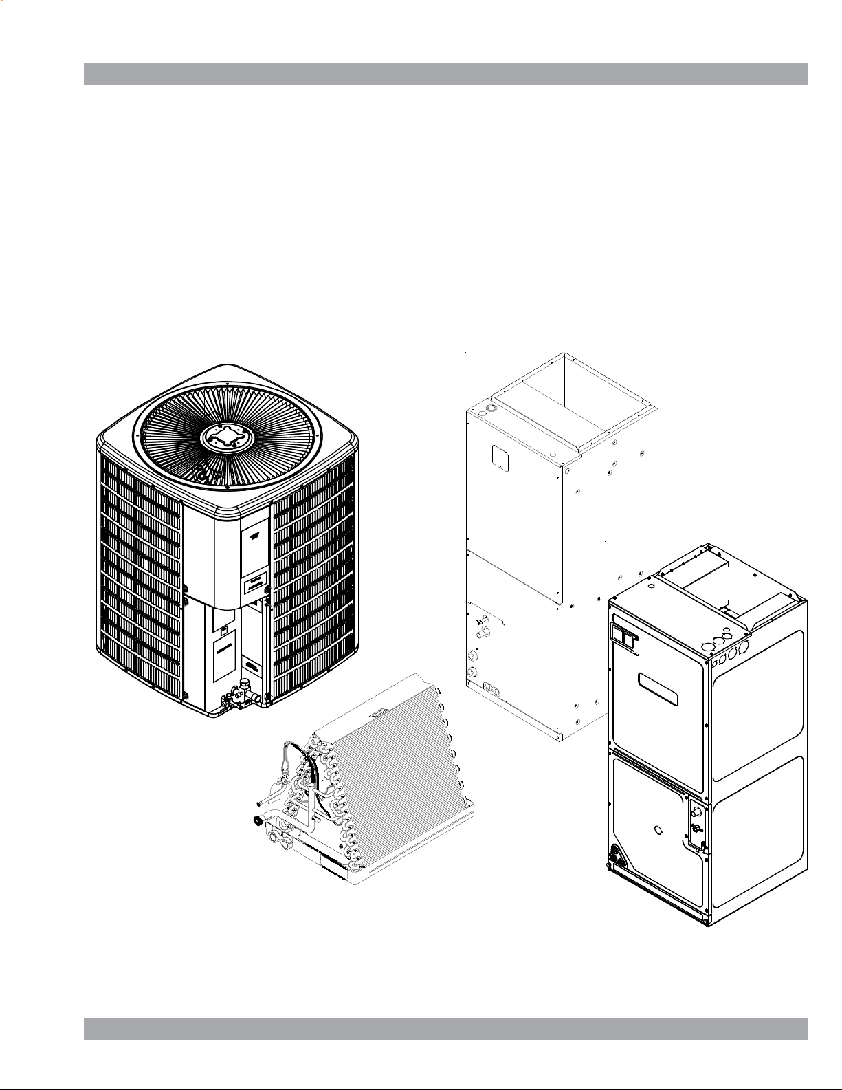
ANX, SSX, ASX, GSX, DSX
Condensing Units,
ANZ, SSZ, ASZ, GSZ, DSZ, VSX, VSZ Split System Heat Pumps
with R-410A Refrigerant
Blowers, Coils, & Accessories
This manual is to be used by qualified, professionally trained HVAC technicians only. The
manufacturer does not assume any responsibility for property damage or personal injury due to
improper service procedures or services performed by an unqualified person.
Copyright © 2006 - 2016 Goodman Manufacturing Company, L.P.
RS6200006r72
August 2016
Page 2
T able of Content s
IMPORT ANT INFORMA TION ...................................................2
PRODUCT IDENTIFICA TION - MODEL TREES ..................... 4
COILS.................................................................................. 6
BLOWERS ..........................................................................7
AIR HANDLERS .................................................................. 8
LIGHT COMMERCIAL .......................................................10
PRODUCT IDENTIFICATION - CHARTS .............................. 11
LIGHT COMMERCIAL .......................................................11
SPLIT SYSTEM HEA T PUMPS..........................................12
AIR HANDLERS ................................................................ 33
COILS................................................................................ 39
ACCESSORIES - LIGHT COMMERCIAL ..............................41
MODELS TO KITS MA TCHUP...........................................42
ASSOCIA TED KITS ...........................................................51
PRODUCT DESIGN .............................................................. 63
SYSTEM OPERA TION ...........................................................66
TROUBLESHOOTING CHART .............................................70
IMPORT ANT INFORMA TION
Pride and workmanship go into every product to provide our customers with quality products. It is possible, however, that during its
lifetime a product may require service. Products should be serviced only by a qualified service technician who is familiar with the
safety procedures required in the repair and who is equipped with the proper tools, parts, testing instruments and the appropriate
service manual. REVIEW ALL SERVICE INFORMATION IN THE APPROPRIATE SERVICE MANUAL BEFORE BEGINNING REPAIRS.
IMPORTANT NOTICES F OR CONSUMERS AND SERVICERS
RECOGNIZE SAFETY SYMBOLS, WORDS AND LABELS
T
HIS UNIT SHOULD NOT BE CONNECTED TO. OR USED IN
CONJUNCTION WITH, ANY DEVICES THAT ARE NOT DESIGN CERTIFIED
FOR USE WITH THIS UNIT OR
NOT BEEN TESTED AND APPROVED BY THE MANUFACTURER
HAVE
ERIOUS PROPERTY DAMAGE OR PERSONAL INJURY, REDUCED UNIT
S
PERFORMANCE
AND/OR HAZARDOUS CONDITIONS MAY RESULT FROM THE USE OF
DEVICES THAT HAVE NOT BEEN APPROVED OR CERTIFIED BY THE
MANUFACTURER
.
.
HIGH VOLTAGE
D
ISCONNECT
UNIT
F
AILURE TO DO SO MAY CAUSE PROPERTY DAMAGE, PERSONAL INJURY
OR DEATH
ALL
POWER BEFORE SERVICING OR INSTALLING THIS
. M
ULTIPLE POWER SOURCES MAY BE PRESENT
.
.
O
TO
PREVENT THE RISK OF PROPERTY DAMAGE, PERSONAL INJURY, OR DEATH
DO NOT STORE COMBUSTIBLE MATERIALS OR USE GASOLINE OR OTHER
FLAMMABLE LIQUIDS OR VAPORS IN THE VICINITY OF THIS APPLICANCE
NLY PERSONNEL THAT HAVE BEEN TRAINED TO INSTALL, ADJUST, SERVICE OR
REPAIR (HEREINAFTER
,
.
MANUAL SHOULD SERVICE THE EQUIPMENT
BE RESPONSIBLE FOR ANY INJURY OR PROPERTY DAMAGE ARISING FROM
IMPROPER SERVICE OR SERVICE PROCEDURES
ASSUME RESPONSIBILITY FOR ANY INJURY OR PROPERTY DAMAGE WHICH MAY
RESULT
. IN
LICENSES TO SERVICE THE EQUIPMENT SPECIFIED IN THIS MANUAL, ONLY
LICENSED PERSONNEL SHOULD SERVICE THE EQUIPMENT
INSTALLATION, ADJUSTMENT, SERVICING OR REPAIR OF THE EQUIPMENT
SPECIFIED IN THIS MANUAL, OR ATTEMPTING TO INSTALL, ADJUST, SERVICE OR
REPAIR THE EQUIPMENT SPECIFIED IN THIS MANUAL WITHOUT PROPER
TRAINING MAY RESULT IN PRODUCT DAMAGE, PROPERTY DAMAGE, PERSONAL
INJURY OR DEATH
, “
SERVICE
”)
THE EQUIPMENT SPECIFIED IN THIS
. THE
MANUFACTURER WILL NOT
. IF
YOU SERVICE THIS UNIT, YOU
ADDITION, IN JURISDICTIONS THAT REQUIRE ONE OR MORE
. I
MPROPER
.
To locate an authorized servicer, please consult your telephone book or the dealer from whom you purchased this product.
For further assistance, please contact:
CONSUMER INFORMA TION LINE
GOODMAN® BRAND PRODUCTS
TOLL FREE
1-877-254-4729 (U.S. only)
email us at: customerservice@goodmanmfg.com
fax us at: (713) 856-1821
(Not a technical assistance line for dealers.)
email us at: customerservice@goodmanmfg.com
AMANA® BRAND PRODUCTS
TOLL FREE
1-877-254-4729 (U.S. only)
fax us at: (713) 856-1821
(Not a technical assistance line for dealers.)
(Not a technical assistance line for dealers.) Your telephone company will bill you for the call.
is a registered trademark of Maytag Corporation or its related companies and is used under license. All rights reserved.
2
Outside the U.S., call 1-713-861-2500.
Page 3
IMPORTANT INFORMATION
SAFE REFRIGERANT HANDLING
While these items will not cover every conceivable situation, they should serve as a useful guide.
R
EFRIGERANTS ARE HEAVIER THAN AIR
YOUR LUNGS OR IN ANY ENCLOSED SPACE
BREATHING OR DEATH
EVER PURGE REFRIGERANT INTO AN ENCLOSED ROOM OR SPACE
• N
ALL REFRIGERANTS MUST BE RECLAIMED
F AN INDOOR LEAK IS SUSPECTED, THOROUGHLY VENTILATE THE ARA
• I
BEFORE BEGINNING WORK
IQUID REFRIGERANT CAN BE VERY COLD
• L
BLINDNESS, AVOID CONTACT WITH REFRIGERANT AND WAR GLOVES AND
GOGGLES
. IF
MEDICAL HELP IMMEDIATELY
LWAYS FOLLOW
• A
POISONOUS GAS WILL BE PRODUCED
:
LIQUID REFRIGERANT DOES CONTACT YOUR SKIN OR EYES, SEEK
EPA
REGULATIONS
. T
HEY CAN “PUSH OUT” THE OXYGEN IN
. TO
AVOID POSSIBLE DIFFICULTY IN
. BY
.
.
. TO
AVOID POSSIBLE FROSTBITE OR
LAW
,
TO
AVOID POSSIBLE EXPLOSION
EVER APPLY FLAME OR STEAM TO A REFRIGERANT CYLINDER
• N
HEAT A CYLINDER FOR FASTER CHARGING, PARTIALLY IMMERSE IT IN WARM
WATER
.
EVER FILL A CYLINDER MORE THAN
• N
EVER ADD ANYTHING OTHER THAN
• N
TO AN
410A
LISTED OR CERTIFIED FOR THE TYPE OF REFRIGERANT USED
• S
TORE CYLINDERS IN A COOL, DRY PLACE
PLATFORM OR A ROLLER
R-4 10A
:
CYLINDER
.
. THE
.
. N
EVER BURN REFRIGERANT, AS
.
TO
AVOID POSSIBLE EXPLOSION, USE ONLY RETURNABLE (NOT DISPOSABLE
SERVICE CYLINDERS WHEN REMOVING REFRIGERANT FROM A SYSTEM
• E
NSURE THE CYLINDER IS FREE OF DAMAGE WHICH COULD LEAD TO A
LEAK OR EXPLOSION
NSURE THE HYDROSTATIC TEST DATE DOES NOT EXCEED
• E
• E
NSURE THE PRESSURE RATING MEETS OR EXCEEDS
.
. IF
YOU MUST
80%
FULL OF LIQUID REFRIGERANT
R-22 TO AN R-22
SERVICE EQUIPMENT USED MUST BE
CYLINDER OR
.
. N
EVER USE A CYLINDER AS A
.
5
YEARS
LBS
.
.
400
.
R-
)
THE U
NITED STATES ENVIRONMENTAL PROTECTION AGENCY
HAS ISSUED VARIOUS REGULATIONS REGARDING THE INTRODUCTION AND
OF
DISPOSAL
FOLLOW
LEAD
MAY
LOCAL
S
YSTEM CONTAMINANTS, IMPROPER SERVICE PROCEDURE AND/OR PHYSICAL
ABUSE AFFECTING HERMETIC COMPRESSOR ELECTRICAL TERMINALS MAY CAUSE
DANGEROUS SYSTEM VENTING
REFRIGERANTS INTRODUCED INTO THIS UNIT
THESE REGULATIONS MAY HARM THE ENVIRONME NT AND CAN
TO
THEH IMPOSITION OF SUBSTANTIAL FINES
VARY BY JURISDICTION
EPA
OFFICE
. S
HOULD QUESTIONS ARISE, CONTACT YOUR
.
. T
.
("EPA")
. F
AILURE TO
HESE REGULATIONS
The successful development of hermetically sealed refrigeration
compressors has completely sealed the compressor's moving
parts and electric motor inside a common housing, minimizing
refrigerant leaks and the hazards sometimes associated with
moving belts, pulleys or couplings.
Fundamental to the design of hermetic compressors is a method
whereby electrical current is transmitted to the compressor
motor through terminal conductors which pass through the
compressor housing wall. These terminals are sealed in a
dielectric material which insulates them from the housing and
maintains the pressure tight integrity of the hermetic compressor. The terminals and their dielectric embedment are strongly
constructed, but are vulnerable to careless compressor installation or maintenance procedures and equally vulnerable to
internal electrical short circuits caused by excessive system
contaminants.
HEN IN DOUBT, DO NOT USE CYLINDER
W
TO
AVOID POSSIBLE INJURY, EXPLOSION OR DEATH, PRACTICE SAFE
HANDLING
OF
REFRIGERANTS
.
.
In either of these instances, an electrical short between the
terminal and the compressor housing may result in the loss of
integrity between the terminal and its dielectric embedment. This
loss may cause the terminals to be expelled, thereby venting the
vaporous and liquid contents of the compressor housing and
system.
A venting compressor terminal normally presents no danger to
anyone, providing the terminal protective cover is properly in
place.
If, however, the terminal protective cover is not properly in place,
a venting terminal may discharge a combination of
(a) hot lubricating oil and refrigerant
(b) flammable mixture (if system is contaminated
with air)
in a stream of spray which may be dangerous to anyone in the
vicinity. Death or serious bodily injury could occur.
Under no circumstances is a hermetic compressor to be electrically energized and/or operated without having the terminal
protective cover properly in place.
See Service Section S-17 for proper servicing.
3
Page 4

PRODUCT IDENTIFICATION
ANZ 13 018 1 AA
1 2 3 4,5 6,7,8 9 10,11
Brand
A -
Amana® brand
Type
N 1 - 208/230V Single-Phase 60 Hz
Deluxe Split System
2 - 220/240V Single-Phase 50 Hz
Type 3 - 208/230V Three-Phase 60 Hz
X: Condenser R-410A 4 - 460V Three-Phase 60 Hz
Z: Heat Pump R-410A 5 - 380/415V Three-Phase 50 Hz
SEER
11 - 11 SEER
13 - 13 SEER
14 - 14 SEER
16 - 16 SEER
18 = 1-1/2 Tons
24 = 2 Tons
30 =
2-1/2 Tons
Major/Minor Revisions
3-1/2 Tons
42 =
48 = 4 Tons
59 = 5 Tons
Engineering
Voltage
Nominal Capacit y
36 = 3 Tons 60 = 5 Tons
61 = 5 Tons
4
Page 5

PRODUCT IDENTIFICATION
SSZ 14 1AA
1 2 3 4,5 9 10,11
Bra nd
G
Goodman® brand
(Standard Feature Set)
S
Goodman® brand
(High Fe ature Set)
A
Amana® brand
Deluxe
D
Goodman® brand
Deluxe
V
Value Line
Type
S 1 - 208/230V Single-Phase 60 Hz
Split System
Type 3 - 208/230V Three-Phas e 60 Hz
X: Condens er R-410A 4 - 460V Three-Phase 60 Hz
Z: Heat Pump R-410A 5 - 380/415V Three-Phas e 50 Hz
036
6,7,8
Engineering
Major/Minor Revisions
Voltage
2 - 220/240V Single-Phase 50 Hz
SEER
13 - 13 SEER 018 = 1-1/2 Tons 042 = 3-1/2 Tons
14 - 14 SEER 024 = 2 Tons 048 = 4 Tons
16 - 16 SEER 030 = 2-1/2 Tons 059 = 5 Tons
18 - 18 SEER 036 = 3 Tons 060 = 5 Tons
038 = 3 Tons
5
Page 6

PRODUCT IDENTIFICATION
A
=
CAP F 1824 A 6 A
1 2 3 4 5,6,7,8 9 10 11,12
Bra nd Engineering*
C Indoor Coil
Unit Applicatio n 2 = R-22
A Upflow/Downflow Coil
H Horizontal A-Coil
Horizontal Slab Coil
S
Coated Coils
T
Nominal Width for Gas Furnace
A = Fits 14" Furnace Cabi net
B = Fi ts 1 7-1/2" Furnace Cabinet
C =
Fi ts 21" Furnace Cabinet
D =Fits 24-1/2" Furnace Cabinet
N
Does Not Apply (Horizontal Slab Coils
Major/Minor Revisions
Ref rigerant Charge
4 = R-410A
6 = R-410A or R-22
Cabinet Finish
U Unpainted
PPainted
N Unpainted Case
Expansion Device
FFlowrator
T 4 - 5 Tons
Expansion Valve 4 - 5 Tons
1824 =
3030 =
3131 =
3636 =
3642 =
3743 =
4860 = Factory-Installed Non-Adjustable
4961 =
Nominal Capacity @ 13 SEER
1-1/2 - 2 Tons
2-1/2 To ns
2-1/2 To ns
3 Tons
3 - 3-1/2 Tons
3 - 3-1/2 Tons
6
Page 7

PRODUCT IDENTIFICATION
A
A
H
MB R 8 00
1,2 3 4 5,6 7 8 9
Bra nd
MB - Modular Blower 1: 208-230V/60Hz/1 P
Type A: F irst Series
R -
Speed
E -
Variable Speed
Airflow A: No Circuit Breaker
8:
12:
16:
20:
800 CFM
1200 CFM
1500 CFM
2000 CFM
B: Circ uit Breaker
1
Electrical
Design Serie s
Circuit Breaker
Factory Heat
00 No Heat
7
Page 8

PRODUCT IDENTIFICATION
W
A
1 2 3 4 5,6,7,8 9 10 11,12
Bra nd Engineering*
A Airhandler
Unit Applicatio n Re frigera nt C harge
C Ceiling Mount PSC Motor 4 = R-410a
DDownflow PSC Motor
Multi Position
E Electrical
Variable Speed
R Multi Position PSC Motor
S Multi Po sition EEM Motor
T Coated Coils
W Wall Mount PSC/EEM Motor
Cabinet Finish 1830 = 1-1/2 - 3-1/2 Tons
U Unpainted 3137 = 3 Tons
PPainted 3642 = 3 - 3-1/2Tons
NUncased
Expansion Device
FFlowrator
T Expansion Valve 1803 = 1-1/2 Tons Cooling/3 kW Electric Hea t
U F 3642 1 6 AA
Major/Minor Revisions
1 208/240V, 1 Phase, 60 Hz
Nominal Capacity
@ 13 SEER Dedicated Application
3636 = 3 Ton
Multi-P osition & Downflow Application
Multi-Position & Do wnflow Application @10 SEER
1729 = 3 Ton
Ceing Mount & Wall Mount Applications
(Nominal C ooling Ca pacity/Electric Heat kW)
1805 = 1-1/2 Tons Cooling/5 kW Electric Hea t
2405 = 2 Ton s Co oling/5 kW Electric Heat
3608 = 3 Ton s Co oling/8 kW Electric Heat
3105 = 1-1/2 - 2-1/2 Tons Cooling/5 kW Electric Hea t
3210 = 2 - 2-1/2 Tons Cooling/5 kW Electric Heat
3705 = 3 Ton s Co oling/5 kW Electric Heat
3708 = 3 Ton s Co oling/8 kW Electric Heat
3710 = 3 Ton s Co oling/10 kW Electric Heat
An "F" in the model number denotes a
Factory Installed Float Switch is present.
All Airhandlers use DIRECT DRIVE MOTORS. Power supply is AC 208-240v, 60 hz, 1 phase.
8
Page 9
PRODUCT IDENTIFICATION
ARUF 18 B1 4AA
123 4 5,6 7 8 910,11
Bra nd Engineering*
A Single-Piece
Airhandler
Unit Applicatio n Re frigerant Charge
C Ceiling Mount PSC Motor 4 = R-410a
R Multi Position PSC Motor
S Multi Po sition EEM Motor Electrica l
W Wall Mount PSC/EEM Motor 1 208/240V, 1 Phase, 60 Hz
Major/Minor Revisions
Cabinet Finish
UUnpainted B =
PPainted C = 21" Wide
NUncased D = 24 -1/2" Wide
Expansion Device
F Flowrator 18 =
T Expansion Valve 24 = 2 Ton s 47 =
1-1/2 Tons
25 = 2 Tons 48 = 4 Tons
2-1/2 - 3 Tons
29 =
2-1/2 Tons
30 =
36 =3 Tons 60 =5 Tons
2-1/2 - 3 Tons
37 =
Nominal Capaci ty @ 13SEER
Cabinet Width
1/2" Wide
17-
3-1/2 Tons
42 =
3-1/2 Tons
49 = 4 Tons
59 = 5 Tons
61 = 5 Tons
Airhandlers use DIRECT DRIVE MOTORS. Power supply is AC 208-230v, 60 hz, 1 phase.
9
Page 10
PRODUCT IDENTIFICATION
A
A
GSX 11 090 1 AA
1 2 3 4,5 6,7,8 9 10,11
LIGHT COMMERCIAL
Bra nd
G - Goodman brand
A - Amana brand
Type
S 1 - 208/230V Single-Phase 60 Hz
Split System
2 - 220/240V Single-Phase 50 Hz
Type 3 - 208/230V Three-Phase 60 Hz
X: Condenser R-410A 4 - 460V Three-Phase 60 Hz
Z: Heat Pump R-410A 5 - 380/415V Three-Phas e 50 Hz
SEER
11 - 11 SEER
13 - 13 SEER
14 - 14 SEER
16 - 16 SEER 036 - 3 Tons
048 - 4 Tons
060 - 5 Tons
090 - 7-1/2 Tons
120 - 10 Tons
Major/Minor Revisions
Engineering
Voltage
Nominal Capacity
10
R 090 A
12 3,4,5 6,7
Bra nd
Single Piece
A
Air Handler
Unit App lication
R 090 7-1/2 Tons
Multi Position
PSC Motor
For use with GSX/GSZ11 Light Commercial models only.
Major/Minor Revisions
Engineering
Nominal Capacity
120 10 Tons
Page 11
PRODUCT IDENTIFICATION
GSX11 LIGHT COMMERCIAL
LIGHT COMMERCIAL
OODMAN® BRAND SPLIT
G
Model/Rev Description
GSX 110 90*AA
GSX 111 20*AA
GSX 111 203 AB
GSX 110 903 AB
GSX 111 204 AB
GSX 110 904 AB
Introduct ion of Goodman Light Comm erc i al 11 SEER, R-410A Condensers .
208-230V and 460V 3 Phas e condensing unit s wi t h new ball valve/bracket s, suction
tube/ as sembly and panel w/ offset .
R410A CONDENSERS 11 SEER
X-
GSZ11 LIGHT COMMERCIAL
OODMAN SPLIT Z-R410A HEAT PUMP 11 SEER
G
Model/Rev Description
GSZ11090*AA
GSZ11120*AA
GSZ110903AB
GSZ111203AB
GSZ110904AB
GSZ111204AB
Introduct ion of Goodman Light Comm erc i al 11 S EER, R-410A Heat P um ps.
208-230V and 460V 3 Phas e R410A heat pump uni t s wi t h new ball valve/bracket s, suction
tube/ as sembly and panel w/ offset .
AR LIGHT COMMERCIAL
SINGLE PIECE
A
Model /Re v Description
AR0904A
AR1204A
Introducat ion of new 7.5 & 10 Ton Air Handler Models, for use with GS X11 and GSZ11
Light Commercial Models.
MU LTI-POSITION PSC MOTOR
R-
11
Page 12
PRODUCT IDENTIFICATION
Split System Heat Pumps
ASZ13
MANA® BRAND SPLIT
A
Model/Rev Description
AS Z130**1AA Initial release of Amana® B rand 13 SEER Heat Pump R410A .
AS Z130**1AB Introduces new revis ions with im proved ci rc uiting for effecti ve defrost.
AS Z130[18, 36-60] 1A B
ASZ130[24-30]1AC
AS Z130[18, 36-60] 1A C
ASZ130[24-30]1AD
AS Z130[18, 36-60] 1A D
ASZ130[24-30]1AE
AS Z130241BA Release of 2 Ton models, converting from 3/8" to 5mm c ondens er c oil s
ASZ130181AF
ASZ130[24-30]1AG
ASZ130481AF
Intro du ces models co ntaini n g crank cas e hea ter, CCH switch a nd u pg ra ded de frost
control.
Relocat i on of low press ure s witch from liquid l i ne t o s uction li ne as a c om pres sor
safeguard to prevent low pressure from entering.
Initial release of models us i ng s ingl e speed PSC mot ors ; removal of low ambient
temperat ure switc h.
Current revers i ng valve c hange from Dunan to new SanHua reversing valve
Current Ranco reversing valve 0151M00020 replac ed by S anHua 0151R00070 revers i ng
valve
R410A HEAT PUMP 13 SEER
Z-
ASZ130361AG
ASZ130421AH
Change from c opper wound motor t o al umi num wound mot or.
12
Page 13
PRODUCT IDENTIFICATION
Split System Heat Pumps
ASZ14
MANA® BRAND SPLIT
A
Model/Rev Description
ASZ140**1AA
AS Z140**1AB Sc rew loc at i ons m oved in the top panel, bas e pans , louvers , and control box c overs.
AS Z140**1AC Horiz ont al styl e louvers.
AS Z140[18, 42-48]1A D
AS Z140[24-36, 60 ] 1 A E
ASZ140361AF
ASZ140421AD
ASZ140[48-60]1AE
AS Z140[18, 30, 36] 1A F
ASZ140241AG
ASZ14[42, 48, 60]1AE
AS Z140241AF Smal l er B 1227315 reversing valve.
ASZ140[18,30,36]1AG
ASZ140241AH
ASZC160[42,48,60]1AF
Initial release of Amana® Brand 14 SEER Heat Pump R410A with sound blanket s and
Coresense c ont rol .
New steel m uffler, and s uc t i on t ubes w/ s hock loop.
TXV & compensator replaced with flowrator & acc um ul at or.
Sanhua (RANCO) reversing valves.
Introduct ion of heat pumps with acc um ulat ors, crank c ase heaters, and upgraded defrost
control.
R410A HEAT PUMP 14 SEER
Z-
AS Z140361BA Chassis siz e reduction from large to m edi um .
ASZ140[18, 30]1AH
ASZ140241AJ
ASZ140[42-60]1AG
ASZ140[18, 30]1AJ
ASZ140241AK
ASZ140[42-60]1AH
ASZ140361BB
ASZ140181AL
ASZ140241AM
ASZ140301AL
ASZ140361BC
ASZ140381AB
ASZ140[42-60]1AK
AS Z140381AA 35" chassis wit h 6-c hannel flowrator and ZP29K5 com pres s or.
AS Z140[18-30]1BA Updated ratings and agenc y i nformati on.
ASZ140[18-60]1KA
AS Z140[421,491, ] K B Motor c hange on 3 & 3. 5T 14 SEER & 2 & 2.5T 16 SEER. Increase blade gap.
AS Z140181KC Change from c opper wound motor to al umi num wound motor.
AS Z140[241, 301, 361, 481, 601] KB
AS Z140[421, 491] KC
Relocat ion of low pressure switch from li qui d line to suction li ne as a compres sor
safeguard to prevent low pressure from entering.
2 speed PS C m ot ors replac ed wit h single speed PS C mot ors.
Revision made for desi gn i m provement.
Introduction of ready 15, 14 SEER heat pumps t o meet t he 2015 energy effici enc y
requirement.
Refrigerant Charge Reduct ion
AS Z140181KD Refrigerant Charge Reduct ion
ASZ140[241,301,361,]KC
Equivalent mot or wi t h Aluminum Windings replacing Copper Windings.
13
Page 14
PRODUCT IDENTIFICATION
Split System Heat Pumps
ASZ16
MANA® BRAND SPLITS
A
Model/Rev Description
AS Z160**1AA Initial release of Amana® B rand 16 SEER Heat Pump R410A .
ASZ160**1AB
AS Z160**1AC Horiz ont al s t yle louvers.
AS Z160**1AD Muffler and st andardiz ed TXV, Compensator using the A S Z18 Seer weldment .
ASZ160241AD
ASZ160[36-60]AE
AS Z160[24, 36] 1A F
AS Z160[48, 60] 1A F
AS Z160[24,36, 48, 60] 1KA Initi al release of Amana® B rand 16 SE E R Heat Pump models
AS Z160[18-48]1LA Initi al release of Am ana® B rand 16 SEER Heat Pum p model s with 9.6+ HS P F
ASZ160601LA Initial release of Amana® Brand 5 Ton 16 SEER, 13 eer Heat Pump models.
AS Z160[241,301] LB Motor change on 3 & 3. 5T 14 SE E R & 2 & 2.5T 16 SEER. Increas e bl ade gap.
AS Z160181LB 16SEER 1.5T Heat Pumps, Remove Hard Start Kit
AS Z160181LC Change from copper wound motor t o al umi num wound mot or.
Introduces m odels with s c rew locations moved in the top panel, base pans, l ouvers, and
control box covers.
Adds new s t eel m uffler, and suction t ubes w/ shock loop.
Sanh ua (RANCO) reversi ng valves.
R410A HEA T PUMP 16 SEER
Z-
ASZ18
MANA® BRAND SPLIT
A
Model/Rev Description
AS Z180**1AB Initial release of Amana® B rand 18 SEER Heat Pum p R410A.
AS Z180[36, 48, 60] 1A C S anhua (RANCO) reversing valves.
R410A HEAT PUMP 18 SEER
Z-
14
Page 15
PRODUCT IDENTIFICATION
Split System Heat Pumps
ANZ13
MANA® BRAND SPLIT SYSTEM
A
Model/Rev Description
ANZ130[18-60]1AA Initi al release of Amana® B rand Spl it System B ase Heat Pump, 13 S eer R-410A units.
ANZ130[18/24/ 30] 1A B Reversing valve change from Dunan to new SanHua reversing valve
ANZ130481AB Ranc o 0151M00020 reversing valve changed to new SanHua 0151R00070 reversing valve
N-
BASE
R410A HEAT PUM P 13 SEER
Z -
ANZ14
MANA® BRAND SPLIT SYSTEM
A
Model/Rev Description
ANZ140(18-60)1AA
ANZ140(24-30)1AB Energy guide updat e.
ANZ140181AB
ANZ140421AB
ANZ140491AB
Introduction of ready 15, 14 SEER heat pumps to meet the 2015 energy effic i enc y
requirement.
Minor revisions on OD units ZP14K6 compressors without hard start k it.
14S 1. 5T HPs ONLY .
Motor c hange on 3 & 3. 5T 14 SEER & 2 & 2.5T 16 SEER. Increase blade gap.
N-
BASE
R410A HEAT PUM P 14 SEER
Z -
ANZ140[ 181 , 301]A C
ANZ140361AB
ANZ140[ 421 , 491]A C
ANZ140[ 481 , 601]A B
ANZ140[181,301]AD
ANZ140361AC
ANZ140241AD Equivalent motor with Aluminum Windings replacing Copper Windings .
Change from c opper wound motor t o al umi num wound mot or.
Refrigerant Charge Reduct i on
Refrigerant Charge Reduct i on
15
Page 16
PRODUCT IDENTIFICATION
Split System Heat Pumps
DSZ16
ELUXE SPLIT
D
Model/Rev Description
DSZ160**1AA Initial releas e of Deluxe Goodm an 2-s t age 16 SEER heat pumps wi t h R-410A.
DSZ160241AC
DSZ16036, 48, 60]1A B
Sanh ua (RANCO) revers in g valves .
R410A H EAT PUMP 16 SE ER
Z-
DSZ18
ELUXE SPLIT
D
Model/Rev Description
DSZ180**1AA Initial releas e of Deluxe Goodm an 2-s t age 18 SEER heat pumps with R-410A.
DSZ180[36, 48, 60] 1AB Sanhua (RANCO) reversing val ves.
R410A HEA T PUMP 18 SEER
Z-
VSZ13
ALUE SPLIT
V
Model/Rev Description
VSZ13**1AA Initial release of Value Line 13 SEER heat pumps with R-410A.
R410A HEAT PUMP 13 SEER
Z-
VS Z130[24 & 30] 1A B Improved circ ui ting for effective defrost .
VS Z130[24 & 36] 1B A Initi al release of models wit h 5mm Smart Coil™.
VS Z130[18, 42, 48] 1AB
VSZ130241BB
VSZ130301AC
VS Z130[24 & 36] 1B C
VSZ130301AE
VS Z130[18, 42 & 48] 1A D
VS Z130[18, 42-60] 1A C
VSZ130301AD
VSZ130241C A
VSZ130181AE
VSZ130421AF
VSZ130361BD
VSZ130301AF
VSZ130481AE
VS Z130421AF Compres sor change from ZP36K 5E P F V 130 t o ZP34K5EPFV130.
VSZ130241C B
VSZ130181AF
VSZ130241BD
VSZ130301AG
Models containing c rank case heater, CCH switch and upgraded defrost control.
Release of si ngle phas e m odel s with new 6 pole motor.
Relocat i on of low press ure s wi t ch from li quid l i ne t o s uction li ne as a c ompressor
safeguard to prevent low pressure from entering.
Release of 2 Ton models with a com pres sor change from ZP21K 5E P F V 130 t o
ZP20K5EPFV130.
Changed from four-piece louver assembly t o a t wo piece louver as sembly . A dded a c orner
post on 26" and 29" c hassis.
Singl e phas e m odels with new 6 pole motor.
Changed from four-piece louver assembly t o a t wo piece louver as sembly . A dded a c orner
post on 26" and 29" c hassis.
2 Ton models changi ng from the current four piec e louver assembl y, to a t wo piece louver
plus a c orner post on Goodman and value series 26" and 29" chass is.
Revers i ng valve c hange from Dunan to new SanHua.
VS Z130481AF Ranc o 0151M00020 reversi ng valve replac ed by SanHua 0151R00070 revers i ng valve
16
Page 17
PRODUCT IDENTIFICATION
Split System Heat Pumps
GSZ13
OODMAN SPLIT
G
Model/Rev Description
GSZ13**1AA Initial releas e wi t h Regal B el oit motor.
GSZ13**1AB
GSZ13**3AA
GSZ13**4AA
GSZ130[24 & 30] 1A C Releas e of mi nor revis ion with improved circ ui ting for effective defrost .
GSZ130[24 & 36] 1B A Initial release of models with 5mm S m art Coil ™.
GSZ130241CA
GSZ130241CB
GSZ130[18, 42-60 ] 1 AC
GSZ130301AD
GSZ130361BB
GSZ130[18,42,48,60]1AD
GSZ130301AE
GSZ130[36,48,60{3,4]AB
GSZ130[48,60{3,4]AB
GSZ130[18,42,48]1AF
GSZ130301AG
GSZ130[36,48]3AD
GSZ130484AC
Initial rel eas e with Broad Ocean mot or.
Release of 2 Ton models with a c ompres sor change from ZP21K 5E P F V 130 t o
ZP20K5EPFV130.
2 Ton model s chang i ng from the cu rrent four piec e l o uver assembly, to a two pi ece louver
plus a corner post on Goodman and value s eries 26" and 29" chas sis.
Relea se of mode l s c ontain i ng crank case h eater, CCH swit ch and up gra d ed d efro st contro l .
Relocat i on of low press ure s wi t ch from li quid l i ne t o s uction li ne as a compress or s afeguard
to prevent low pres s ure from entering.
Changing from t he current four piec e l ouver assembly, to a two piec e l ouver plus a corner
post on Goodman and value series 26" and 29" chass is.
R410A HEAT PUMP 13 SEER
Z-
GSZ130361BC
GSZ130[42 & 48] 1A E
GSZ130361BD
GSZ130421AF
GSZ130[36 & 48] 3A C Releas e of 3 phase m odels with new 6 pole mot or.
GSZ14**1AA Initial release of 14 SEER models.
GSZ130481AG
GSZ130483AE
GSZ130484AD
Release of models with new 6 pole m ot or/ fan com bination.
Models with new 6 pole motor/fan com bi nat ion. Changing from the current four piec e louver
assembly, to a two piece l ouver plus a corner post on Goodman and value series 26" and
29" chassis.
Release of two piec e l ouver plus corner post on 26" and 29" c has sis with compres sor
changing from ZP36K5EPFV130 t o ZP34K5E P F V 130.
Replaced Ranco revers ing valve 0151M00020 wit h SanHua 0151R00070 revers i ng valve .
17
Page 18
PRODUCT IDENTIFICATION
Split System Heat Pumps
GSZ14
OODMAN SPLIT
G
Model/Rev Description
GSZ140(18-60) 1KA
GSZ140491AA
GSZ140(18-30)1KB Energy guide update. P CB DM160 with new software.
GSZ140301KC
GSZ140361KB
Introduction of ready 15 14 SEER heat pumps to meet the 2015 energy efficiency
requirement.
Migrat ing from c opper t o alum inum m ot ors.
R410A HEA T PUMP 14 SEER
Z-
GSZ140 [421,491]KB Motor c ha n ge on 3 & 3.5 T 14 SEER & 2 & 2.5 T 16 SEER. Inc r ease blade gap.
GSZ140 181KC
GSZ140 361KC
GSZ140[241,301]KD
GSZ140[481,601]KB
GSZ140[241, 301]KE
GSZ140[481, 601]KC
GSZ1401 81KD
GSZ140[421, 491]KC
Refrigerant charge reduction.
New model revisions, GSZ140241KD, GSZ140301KD, GSZ140481KB and GSZ140601KB
will have the BOMs cha ng ed and ha ve a lower refrigerant cha rg e.
New model revisions to deplete current overstock o f Ranco reversing valves
Change from c opper wound motor t o al umi num wound mot or.
Refrigerant Charge Reduct i on
GSZ1402 41KF
Equivalent motor with Aluminum Windings replac i ng Copper W i ndings .
18
Page 19
PRODUCT IDENTIFICATION
Split System Heat Pumps
GSZ16
OODMAN SPLIT
G
Model/Rev Description
GSZ160[18-48]1B A Initial release of Goodman 16 SEER, 13 EER Heat P umps with 9. 0+ HSPF
GSZ1160601BA Initial release of Goodman 5 Ton 16 SEER, 13 EER Heat Pumps
GSZ160241BB
GSZ160301BB
GSZ160181BB 16 SEER 1.5T Heat Pumps, Remove Hard Start Kit
GSZ160181BC E qui valent motor wit h A l um inum Windings replacing Copper Windings .
Motor c hange on 3 & 3. 5T 14 SEER & 2 & 2.5T 16 SEER. Increase blade gap.
R410A HEA T PUMP 16 SEER
Z-
VSZ14
ALUE SPLIT
V
Model/Rev Description
VS Z14[018-060]1AA Introduct i on of ready 15, 14 SEER heat pum ps t o m eet the 2015 effic iency requirement.
VS Z140(18-30)1AB Energy gui de updat e. P CB DM160 wit h new s oftware.
R410A H E AT PUMP 14 SE ER
Z-
VS Z140421AB
VS Z140491AB
VSZ140[181 ,301]AC
VSZ140[361,481,601]AB
VSZ140[181 , 301]AD
VSZ140361AC
VSZ140[241 , 421, 491]AC
VSZ140241AD
Motor change on 3 & 3.5T 14 SEER & 2 & 2.5T 16 SEER. Increase blade gap.
Refrigerant charge reduction.
Change from c opper wound motor t o alum i num wound motor.
Refrigerant Charge Reduct i on
Equivalent motor with Aluminum Windings replac i ng Copper W indi ngs .
19
Page 20
PRODUCT IDENTIFICATION
Split System Heat Pumps
SSZ14
PECIAL HIGH FEA TURE SPLIT
S
Model/Rev Description
SS Z140**1AA Initial rel eas e of Goodman 14 SEER Heat Pum p R410A.
SS Z140**1AB Sc rew locations m oved in t he t op panel, base pans, louvers, and c ont rol box c overs.
SS Z140**1AC Broad Ocean Motors.
SSZ140181AC
SSZ140241AF
SSZ140301AD
SSZ140361AF
SSZ140[42-60]1AD
SS Z140241AG S m al l er B 1227315 reversing valve.
SS Z140[18, 30, 42-60] A E
SSZ140241AH
SSZ140361AG
SS Z140[18, 30, 42-60] A F
SSZ140241AJ
SSZ140361AH
SSZ140[18,30]1AH
SSZ140241AL
SSZ140361BB
SS Z140140[18, 30] 1A J
SS Z140[19, 25] 1A C
SS Z140[31, 37] 1A C
SSZ140241AM
SSZ140361BCC
SSZ140381AB
SSZ140140381AB
SSZ140[42-60]AH
SSZ140[18-60]1AD
SSZ140361AF
SSZ140[42-60]1AD
SS Z140381AA Initial release of 35" c hassis with 6-channel flowrator and ZP29K5 c ompres sor.
Discharge line mufflers added.
Added dis charge line mufflers. Replac ed TXV and compens at or wit h flowrator and
accumulator.
Sanh ua (RANCO) reversi ng valves.
Introduct i on of heat pumps wi t h accumulat ors, crank case heaters , and upgraded defrost
control.
Changed from four-piece louver assembly t o a t wo piece louver assembly. Added a c orner
post on Goodman 26" and 29" chass is.
Revi sion made for design improvement.
Relocat i on of low press ure s wi t ch from li quid l i ne t o sucti on li ne as a compress or
safeguard to prevent low pressure from entering.
Chassis size reduction from large to medium.
R410A HEAT PUMP 14 SEER
Z-
SS Z140[18-30]1BA Updated rat i ngs and agenc y information.
SSZ140241BB
SSZ140251AE
20
Change from c opper wound motor t o al umi num wound mot or.
Page 21

PRODUCT IDENTIFICATION
Split System Heat Pumps
SSZ16
PECIAL HIGH FEATURE SPLIT
S
Model/Rev Description
SS Z160**1AA Initial release of Goodman 16 SEER Heat Pump R410A.
SS Z160**1AB Sc rew locations m oved in t he t op panel, bas e pans, louvers, and control box covers .
SSZ160**1AC
SSZ16[024-48]1AC
SSZ160601AD
SSZ160361AF
SSZ160[42-60]1AD
SSZ160241AF
SS Z160[36, 48] 1A D
SSZ160601AE
SSZ160241AF
SSZ160[36-48]1AE
SSZ160601BA
SSZ160241AH
Broad Oc ean Mot or. Updat ed muffler and st andardiz ed TXV. Compensator usi ng ASZ18
SEER weldment to the SSZ160601AC.
Discharge line mufflers added.
Added dis charge line mufflers. Replac ed TXV and compens at or wit h flowrator and
accumulator.
Sanh ua (RANCO) reversi ng valves.
Introduct i on of heat pumps wi t h ac cumulators , crankcase heaters , and upgraded defrost
control.
Changed from four-piece louver assembly t o a t wo piece louver as sembly . A dded a c orner
post on Goodman 26" and 29" chass is.
R410A HEAT PUMP 16 SEER
Z-
SS Z160601BB Ultrat ech® com pres sor
SS Z160241AK Change from c opper wound motor t o al um inum wound mot or.
21
Page 22
PRODUCT IDENTIFICATION
Split System Condensers
GSX13
OODMAN BRAND SPLIT
G
Model/Rev Description
GSX130**1AA Init ial release of Goodman 13 SEER R-410A Condensers wit h Regal B el oit motors
GSX 130 61[1/3/4]AA
GSX 130 363 AB
GSX 130 484 AB
GSX 130 603 AB
GSX 130 604 AB
GSX130**1AB Broad Ocean mot ors .
GSX130483AB 3 Phase model with new 6 pole mot or.
GSX 130 483 AC
GSX 130 181 EA
GSX 130 181 EB
GSX 130 **1BA
GSX 130 **3AA
GSX 130 **4AA
GSX130301BB Replac ed fan motor t o -294 and fan blade to -18 on GSX130301BA model s.
Introduct i on of Goodman 13 SE E R R-410A Condensers that supplem ent our current 5 ton
models.
Changed from t he c urrent four piec e louver assembl y, to a t wo piece louver plus a corner
post on Goodman and value series 26" and 29" chas sis.
3 phase model changing from the current four piece l ouver assembl y, to a t wo piece louver
plus a c orner post on Goodman and value series 26" and 29" chass is.
Introduct i on of 1.5 t on c ondens er wit h Rec hi Compres sor.
Introduct i on of Goodman 13 SE E R R-410A Condensers using Smart Coil ® coils . Units will
have new louvers bec ause units are s m al ler. Pist on size c hange. Ot her components
unchanged.
R410A CONDENSERS 13 SEER
X-
GSX130[42, 48]1BC
GSX 130 301 BC
GSX 130 601 BB
GSX130[42, 48] 1BB New 6 pole motor/fan c ombi nat i on.
GSX130181CA Rot ary compress or.
GSX 130 421 C A
GSX 130 481 C A
GSX130361CA Replaced current c om pres s or with compres s or ZP29K5E PFV130.
GSX130[18-36]1DA Condenser c onversion to 23" c hassis for the 1. 5 - 3 t on m odels.
GSX 130 181 ED
GSX 130 31D B
GSX130361EA Introduction of Goodman 3 ton conversi on from 29" chass is to 26".
GSX 130 361 EB
GSX130371AA Improved decibel rat i ngs for Canadian mark et .
GSX130181EF Change from m ot or 0131M00276 to 0131M 00593 on unit s GSX130181 & VS X130181
Changed from t he c urrent four piec e louver assembl y, to a t wo piece louver plus a corner
post on Goodman and value series 26" and 29" chas sis.
Introduct i on of Goodman 3.5 and 4 t on 13 SEER condens i ng unit s with reci proc at i ng
compressor.
Changed from a 4 leg Rechi Compres sor 50N382XV-ZAKM to 3 Leg Rec hi Com pres s or
50N382XV -5AKM. Changed Suc tion line Assy from 0210R01608 to 0210R01406. This
minor
Improved coil ci rc ui t assembl y for greater capacity /effici ency and a new disc harge t ubi ng
assembly.
Changed from t he c urrent four piec e louver assembl y, to a t wo piece louver plus a corner
post on Goodman and value series 26" and 29" chas sis.
GSX130363AD Change from copper wound mot or t o alum i num wound mot or.
22
Page 23
PRODUCT IDENTIFICATION
Split System Condensers
GSX14
OODMA N BRA ND SPLIT
G
Model/Rev Description
GSX14**1AA Introduction of Goodman 14 SEER R-410A m odels.
GSX 140 [18-19]1KA
GSX 140 [24-25]1KA
GSX 140 [30-31]1KA
GSX 140 [36-37]1KA
GSX140[42, 48, 60] 1KA
GSX140241KB Replac ed 1/ 12hp fan motor with 1/8hp fan motor.
GSX140311AA Introduction of 12.2 EER ai r c onditioning units.
GSX140[30-36,42]1KB Migrat i ng from copper t o alum i num motors.
GSX 140 251 LA
GSX140241LB
GSX140191KB
GSX140361KC
GSX140371KB
GSX140421KC
GSX140 [431,481,601]KB
Goodman
condens er 5mm arc hi t ecture with updat ed s croll com pres sors.
Changed compres s or from K5 to K6, Changed coi l slab from 25" tal l t o 30" t al l , Changed
louvers from 24" tall to 29" tall
Create minor revis i ons of the new Rechi 2. 0T units to consume the ex cess inventory of
19P fan motor
Remove HS Kit from Control Panels of c ondens er unit s with updated
ZP14K6E scroll compressors.
Refrigerant charge reduction.
plit X 14 Seer Condensing unit s. Introduci ng t he Goodm an 14 SEER standard
S
R410A CONDENSERS 14 SEER
X-
GSX140311KB
GSX140371KC
GSX140431KC
Change from c opper wound motor t o al um inum wound mot or.
GSX16
GOODMAN BRAND SPL IT X-R41 0A CONDENSERS 15 AND 16 SEER
Model/Rev Description
GSX160**1FA Initi al release of the Goodman 16 S E E R R410A Condensers.
GSX160611FA New high cap ac i t y 5 ton model t hat will s uppl em ent the c urrent GSX160601 m odel s .
GSX160[18-61]1F B M i nor revision for GSX16s to i nclude ball valves 0151R00045 and 0151R00046.
GSX160601GA 7mm coils .
GSX160(48/60/61)1F B Ball valve cha nge from 015 1R00046 to 0151R00081
GSX160(18/24/30/36)1FC Migrat i ng from c opper t o al uminum mot ors.
GSX160(18/24/30/36)1FC
GSX160(42/48/60/61)1FC
GSX160311AA
GSX160371AA
Bal l Valve Re-work 0151R00045 & 0151R00046
Initi al release c reates and l aunches 2 new SKUs i n the 16 SE ER singl e-stage A C
product line.
GSX160[ 241, 301, 601]FE
GSX160[311,371]AB
Refrigerant charge reduction.
Equivalent motor with Aluminum Windings repla c ing Copper Windings.
23
Page 24
PRODUCT IDENTIFICATION
Revisi
Split System Condensers
SSX14
PECI AL HIGH FEATURE SPLIT
S
Model/Rev Description
SS X140**1AA Initi al releas e of Goodman 14 SEER AC 410A.
SSX140**1AB
SS X14018, 241AC Revised condenser c oi ls by removing [1] haripin.
SS X140301AC M odel contains t he Broad Oc ean motor 0131M00060
SS X14036-601AC Models contain the B road Oc ean m ot or 0131M00061
SS X14030,361A D Revi s ed c ondens er coils by removing [1] haripi n.
SS X140421AD Introduc es SSX140421A in 29" base pan
SSX140[18-24]1BA
SSX140[30-36]1BA
SSX140421CA
SSX140[18-36]1BC
SSX140421CC
SSX140[18-36]1BD
SSX140421CD
SSX140481BB
SSX140601AG
SSX140421BA
ons have s crew locations m oved in the top panel, base pans , louvers, and control
box covers.
Convert s 1.5 - 3.5 t on c ondenser coil t ubes from 3/ 8" t ube diameter to 5mm t ube
diameter .
Changing from t he current four piec e l ouver assembly, to a two piec e l ouver plus a corner
post on Goodman and value series 26" and 29" chas sis.
Revi sion made for design improvement.
Revi sion for SSZ140421B* in 29 base pan and it will the reduce the unit charge from 180
oz. to 170 oz. and replac e t he 1/ 4 hp out door unit m ot or wit h 1/6 hp motor.
R410A CONDENSERS 14 SEER
X-
SS X14030-421AE Revised c ondens er coils by removi ng [ 1] haripin.
SSX140[18-48]1BA
SSX14042-481CA
SSX140[18-36]1BB
SSX140421CB
SSX140601AF
Introduct i on of Goodman 14 SE E R R-410A Condensers wi t h S m art Coil ® Coil s.
Relocat i on of low press ure s wi t ch from li quid l i ne t o s uction li ne as a compress or
safeguard to prevent low pressure from entering.
24
Page 25
PRODUCT IDENTIFICATION
Split System Condensers
SSX16
PECIA L HIGH FEATURE SPLIT
S
Model/Rev Description
SS X160**1AA Introduces Goodman 16 SEER AC 410A
SSX160**1AB
SSX160**1AB
SSX160591AA
SS X160[24, 36, 48] 1BA
SS X160[30 & 42] 1A A
SS X160[24, 36] 1B C
SS X160[30, 42] 1A B
SS X160601BA ZPS49K compress or.
SSX160[24,36,60]1BB
New revisions have screw locati ons m oved in the top panel, bas e pans , louvers, and
cont rol box covers.
New revisions have screw locati ons m oved in the top panel, bas e pans , louvers, and
cont rol box covers.
SmartCoil® coils.
Changing from t he current four piec e louver assembl y, to a t wo piec e l ouver plus a corner
post on Goodman and value series 26" and 29" chas sis.
Relocat i on of low press ure s witch from liquid l ine t o suct i on line as a compres s or
safeguard to prevent low pressure from entering.
R410A CONDEN SER 16 SEER
X-
DSX16
ELUXE SPLIT
D
Model/Rev Description
DSX160**1AA Initial release of Goodman 2-stage, 16 SEER condensing units with R-410A.
R410A HEAT PUMP 16 SEER
X-
DSX160[24, 36]1BA Conversi on of 2 & 3 t on m odels to SmartCoil ® Coils.
DSX160241BC Introduces Ultratec h® 2.0 com pres sor changes.
DSX18
ELU XE SPLIT
D
Model/Rev Description
DSXC18**1AA Inti al release of 2-stage condensing uni t s wi t h R-410A communic at i ng m odels.
DSXC18036AB
DSXC18048AB
DSXC18060AB
DSXC18036AC
DSXC180[48-60]AC Intial releas e of Ultrat ech 2.0 to communic at i ng c ondens i ng units
Updated wiring diagram wit h not es for com m unicating c ondens i ng units.
Replaced ex i s ting compres sor ZPS 20K4EPFV230 t o ZPS 20K 5E PFV130 & ex i sting
com pres s or ZPS30K 4E PFV230 t o ZPS30K 5E P F V 130 for comm uni cating c ondens ing
units.
R410A HEAT PUMP 18 SEER
X-
25
Page 26
PRODUCT IDENTIFICATION
Split System Condensers
VSX13
ALUE SPLIT
V
Model/Rev Description
VSX130[18-48]1AA Introduces Value Line 13 SEER condensing units with R-410A.
VS X130611AA S upplem ent s the 5 ton model GS X130611 to enhanc e performance.
VS X130301AB Replac ed fan mot or to -294 and fan blade to -18 on the V S X130301AA .
VSX130301AC
VSX130[42-48]1AC
VS X130[42-48]1AB Replaced with 6-pole mot or and Copeland compressor.
VS X130181BA Rotary compress or.
VSX130181EA
VSX130181EB
VSX130181ED
VSX130241BA
VS X130361BA Replac ed c urrent c om pres sor with com pres sor ZP29K5EPFV130.
VSX130361EB
Changed from c urrent four piece l ouver assembly t o a t wo pi ec e louver assem bly plus a
corner post on Goodm an and value s eries 26" and 29" c has sis.
Introduct ion of 1.5 t on condenser with Rec hi Compres sor.
Changed 4-leg Rec hi Com pres sor 50N382XV-ZAKM t o 3-Leg Rechi Compres sor
50N382XV -5AKM. Changed Suc t i on l i ne Assy from 0210R01608 to 0210R01406.
2.0 t on c ondens i ng units wit h alum i num coils, aluminum m anifolds w/exi s ting sc roll
compressor.
Changed from c urrent four piece l ouver assembly , to a two piece louver plus a corner pos t
on Goodman and value series 26" and 29" chass is.
R410A CONDENSER 13 SEER
X-
VS X130601BA Condensi ng unit s with Sm art Coil ® coils .
VSX130601BB
VSX130421BA
VSX130481BA
VS X130[18-36]1DA 3.5 and 4 t on 13 S E E R Condensers conversion to 23" chass is for the 1. 5 - 3 t on m odels.
VSX130301DB
VSX130301EA
VSX130241EA
VS X130371AA 2. 5 13 SEER Condensers wit h i m proved deci bel ratings for Canadian market.
VS X130241EB Compres s or wires yellow, red and blac k changing from 40" t o 45" .
VS X130181EF Change from m ot or 0131M00276 t o 0131M00593 on unit s G S X130181 & V S X130181
VSX130241EC
VSX130301AE
VSX130[361,6 01]ED
VSX130[421,4 81]AE
Changing from t he current four piec e l ouver assembly, to a two piec e l ouver plus a corner
post on Goodman and value series 26" and 29" chass is.
3.5 and 4 ton 13 S E ER condensing units wit h rec iprocating com pressor.
2.5 13 SEER Condensers wit h i m proved coi l c i rc ui t assembl y for greater
capac i t y/efficiency and the c reat i on of a new disc harge t ubi ng as s em bl y.
3 Ton 13 SEER Condensers release of 3 ton models converting from 29" chassis to 26"
chassis.
2.0 Ton 13 SEE R Condensers wit h Rec hi Compres sor, converting 23" c hassis to 26"
chassis
Refrigerant charge reduction.
26
Page 27
PRODUCT IDENTIFICATION
Split System Condensers
VSX14
ALUE SPLIT
V
Model/Rev Description
VSX140[18-19]1AA
VSX140[24-25]1AA
VSX140[30-31]1AA
VSX140[36-37]1AA
VS X140[42, 48, 60]1AA
VS X140241AB Replac ed 1/ 12hp fan mot or with 1/ 8hp fan mot or.
VSX140251BA
VSX140241BB
VS X140191KB
Introducing the 14 SEER standard condenser 5mm architecture with updated s croll
compressors.
Changed compressor from K 5 t o K 6, Changed coi l s l ab from 25" tall to 30" t al l , Changed
louvers from 24" t al l t o 29" t al l
Create minor revisions of the new Rechi 2.0T units to consume the excess inventory of
19P fan motor
Remove HS Kit from Control Panels of condenser units with upda ted
R410A CONDENSER 13 SEER
X-
ZP14K6 E sc roll compressors.
VS X140[301, 311] A B
VSX140[361-431]AC
VSX140301BA
Change from c opper wound motor t o al umi num wound mot or.
Copeland to Rechi 2.5 T update s uc t tube, fix l iq l i ne as sy, fix wiring diagram, change
charge qty.
27
Page 28
PRODUCT IDENTIFICATION
Split System Condensers
ANX13
MANA® BRAND SPLIT SY STEM
A
Model/Rev Description
ANX130[18-24]1AA
ANX130[30-61]1AA Init ial release.
ANX130241BA Convert ANX13/14 1. 5 and 2 ton m odels to Rechi compress ors .
ANX130[301-601]A D Refrigerant Charge Reduc ti on
Launch of the Tier 1.5T & 2.0T models. Launc hed with 26" chas i s to accommodate
horizont al sty l e louvers.
N-
BASE
R410A CONDENSERS 13 SEER
X-
ANX14
MANA® BRAND SPLIT SYSTEM
A
Model/Rev Description
ANX140[18-60]1A A
ANX140241AB Replac es 1/12hp fan motor with 1/8hp fan motor.
ANX140431AA Introduction of ready 15, 12.2 EE R air c onditioning units.
ANX140251BA
ANX140191AB
ANX140181BA
ANX140241BA
Introducing t he A m ana
updated scroll com pres sors.
Changed compressor from K5 to K6, Changed coi l slab from 25" tall t o 30" tall, Changed
louvers from 24" t al l t o 29" t al l
Remove HS Kit from Control Panels of c ondens er unit s wi t h updat ed
ZP14K6E scroll compressors.
Convert A NX13/14 1. 5 and 2 t on model s to Rechi c ompres sors.
BASE
N-
®
Brand 14 SEER standard condenser 5mm architecture with
R410A CONDENSERS 14 SEER
X-
ANX140[301-371]A B
ANX140[421,431] A B
ANX140481AB
ANX140601AB
ANX140[361,371] A C
ANX140[421,431] A C
Change from c opper wound motor t o alum i num wound mot or.
Refrigerant Charge Reduct i on
Refrigerant Charge Reduct i on
28
Page 29
PRODUCT IDENTIFICATION
Split System Condensers
ASX13
MANA® BRAND SPLIT
A
Model/Rev Description
ASX130**1AA
ASX130611AA
ASX130611AA
ASX130**1BA
ASX130**1CB
AS X130181DA Init i al release of models wit h new 266 fan motor; Low pressure switch removed.
ASX130181DB
ASX130[24-48]1CD
ASX130601CC
ASX130[24-48]1CC
ASX130601CB
AS X130361DA Release of 3 ton m odels with a 26" c hassis.
Initial release new models of Am ana
Initial release of new models of Amana® Brand Deluxe 13 SEER AC R410A conditioners;
replaced A S X130601* models.
Introduct i on of Amana
5 ton models.
Initial release of models us i ng Sm art Coil
si z e changed; other com ponent s unchanged.
Relocat i on of low press ure s witch from liquid l i ne t o s uction li ne. Compres sor safeguard to
prevent low pressure from entering.
Low pressure s witch 013M00082 added; updated wi ring diagram.
Initial release of models wit h single speed P S C mot ors; Does not c ont ai n a l ow pressure
swit ch, low ambi ent t em perat ure s wit ch and relay.
®
brand 13 SEER R-410A Condensers that supplement our current
CONDENSERS 13 SEER
X-
®
Brand Deluxe 13 SEER AC R410A conditioners.
®
coi ls. Sm al l er unit s with new louvers. P iston
AS X130361DE Refrigerant Charge Reducti on
29
Page 30
PRODUCT IDENTIFICATION
MANA® BRAND SPLIT
A
Model/Rev Description
ASX14
CONDENSERS 14 SEER
X-
Split System Condensers
ASX140**1AA
AS X140**1AB Sc rew l oc ations m oved in the t op panel, base pans , l ouvers, and control box covers.
AS X140**1AC Horizontal sty le louvers.
AS X14018-361AD Revis ed c ondenser coil s by removing (1) hairpin. R410A quanti t y reduced by 6 ounc es.
AS X140421AD Initial releas e of m odel ASX140421A i n 2 9" base pan
ASX140421BA
ASX14018-361BA
ASX140[42-48]1CA
ASX140[18-30]1BA
ASX140[42-48]1CA
ASX140[18-36]1CB
ASX140421DB
ASX140601BB
Initi al rel ease of models of Amana
29" pl at form. Uni t charge reduced from 180 oz. to 170 oz . 1/ 4 hp outdoor unit motor
replac ed wit h 1/ 6 hp m ot or.
1.5 - 3. 5 t on condenser c oi l tubes c onverted from 3/8" t ube di am et er to 5mm tube
diameter.
Initi al rel ease of models using SmartCoil ® coil s.
Low press ure switc h rel ocated from liq uid l i ne t o sucti on l i ne as a compressor safeguard
to prevent low pres sure from enteri ng.
®
Brand Deluxe 14 SE ER AC R410A conditi oners.
ASX140[24-36]1CC
ASX140421DC
ASX140481CB
ASX140601BC
ASX140181DB
ASX140[24-36]1CD
ASX140421DD
ASX140481CC
ASX140601BD
ASX140181DD
ASX140[24-48]1CE
ASX140421DE
ASX140601BE
ASX140181DA Init i al release of models wit h new 2 66 fan m otor; Low pres sure swit ch removed.
AS X140[18-19, 24-25] 1K A
AS X140[30-31, 36-37] 1K A
AS X140[42, 48, 60]1K A
AS X140241KB 1/8 hp fan mot or replaced 1/12 hp fan mot or.
Initi al rel ease of models with single s peed PSC mot ors; Does not cont ain a low pressure
swi t ch, low ambi ent temperat ure switc h and rel ay .
Low pressure switch added.
Desi gn im provement.
Initi al rel ease of 5mm architecture with updated s croll compressors.
30
Page 31

PRODUCT IDENTIFICATION
ASX14
MANA® BRAND SPLIT
A
Model/Rev Description
AS X140[18-19, 24-25] 1K A
AS X140[30-31, 36-37] 1K A
AS X140[42, 48, 60] 1K A
AS X140241KB 1/8 hp fan motor replac ed 1/ 12 hp fan motor.
AS X140241LA A S X140251LA
AS X140191KB
Initial release of 5mm arc hitecture wit h updat ed s croll com pres s ors .
Changed compres s or from K5 t o K 6, Changed coi l slab from 25" tall t o 30" t al l , Changed
louvers from 24" t al l t o 29" t al l
Remove HS Kit from Control P anel s of c ondens er unit s wi t h updat ed
ZP14K6E scroll compressors.
CONDENSERS 14 SEER
X-
Split System Condensers
AS X140241LA
AS X 140[301-431]K B Change from copper wound motor to alum inum wound mot or.
AS X 140[481, 601] K B Refrigerant Charge Reduct i on
AS X 140[361, 371, 421, 431] K C
AS X160[241, 301] FC
Change compres s or from K6 t o K 5 on A S X140241 and DX14SA0241
Refrigerant Charge Reduct i on
31
Page 32

PRODUCT IDENTIFICATION
Split System Condensers
ASX16
MANA® BRAND SPLIT
A
Model/Rev Description
AS X160**1AB S c rew locations m oved in t he t op panel, base pans, louvers, and c ont rol box covers.
AS X160**1AC Horizontal styl e louvers.
AS X160**1FA Si ngle speed outdoor fan.
AS X160611FA High c apac ity 5 ton m odels that supplement t he current ASX160601 models.
AS X160611GA 7mm coils.
AS X160[24-60] 1BA Wiring diagram updated with notes.
ASX160[24/36]1CA
AS X160(48/60/ 61)1FB Ball valve change from 0151R00046 to 0151R00081
ASX160311AA
ASX160371AA
AS X160[181-421]F B Change from c opper wound mot or t o alum i num wound mot or.
AS X160601FC Refrigerant charge reduction
AS X160[311, 371] A B Equivalent m ot or wit h A l um inum Windings replacing Copper Windings.
Initial release of Conversion of 2 & 3 t on model s to SmartCoil
Initial release creates and launches 2 new S K Us i n t he 16 S E ER single-s t age A C product
line.
CONDENSERS 16 SEER
X-
®
coils.
Model/Rev Description
ASX180**1AB
32
ASX18
MANA® BRAND SPLIT
A
Initial release new models of Amana
CONDENSERS 18 SEER
X-
®
Brand Deluxe 18 SEER AC R410A conditioners.
Page 33

PRODUCT IDENTIFICATION
ACNF
SINGLE PIECE AIR HA NDLER CEILING MOUNT N-UNCASED FLOWATER
A-
Model/Rev Description
ACNF****1AA Release of all models of 13 SEER Dayton uncased air handlers.
Air Handlers
ACNF****16AA
ACNF* ** * 1A B Drain pan m a terial c ha nge.
ACNF** * * 1B A Current wavey fin de sign wit h repl a ced new louvered fin desi gn
ACNF****16DA
ACNF180[51-81]6DB
ACNF240[51-81]6DB
ACNF241016DB
ACNF300[51-81]6DB
ACNF301016DB
ACNF250[01/05/06/08/]16AA
ACNF251016AA
ACNF310[01/05/06/08/10]16AA
Release of all models of 13 SEER Dayton uncased air handlers suitable for use with R-22
& R-410A.
Convert ed copper coi l s, man i fold s, hairpi ns, flowrators, 90° flowrator st ub to alumi num .
Convers i on o f c oppe r 3/8" ret urn b ends to al um i nu m 5/16" ret urn bend s.
UL1995 heat er change.
Change in the air handl er design. The motor changed from an exis ting PS C t o a const ant
torqu e motor.
ADPF
SINGLE PIECE DOWNFLOW AIR HANDLER PSC MOTOR PAINTED FLOWATER
A-
Model/Rev Description
ADPF ** **16A A Introducti on of new 13 SEE R A i r Handler Models suitable for use wit h R-22 and R-410A.
ADPF364 216 AB
ADPF486 016 AB
ADPF304 216 AC
ADPF****1B A Replacement of all ARPF c oil s using wavy fin with louver enhanced fin.
ADPF182 416 CA
ADPF486 016 CA
Replacem ent of the c urrent spot welded blower housing with the same cinched or c rim ped
desi gn us ed on t he 80% furnace li ne.
Replacem ent of the c urrent spot welded blower housing with the same cinched or c rim ped
desi gn us ed on t he 80% furnace li ne.
Replacem ent of the c urrent spot welded blower housing with the same cinched or c rim ped
desi gn us ed on t he 80% furnace li ne.
Replacem ent of exi s ting air handler copper coi l s and ot her as sociat ed parts with
aluminum components.
33
Page 34

PRODUCT IDENTIFICATION
Air Handlers
AEPF
SINGLE PIECE E-MU LTI-POSITION VARIABLE SPEED PAINTED FLOWATER
A-
Model/Rev Description
AEPF****16AA Introducation of new 13 SEER Air Handler Models s ui t abl e for use wit h R-22 and R-410A.
AEPF****16BA Introduction of new models adding lower kW hit kit s on the S& R plat e.
AEPF****16BB
AEPF****16CA Replacement of all A RP F c oi l s using wavy fin wit h l ouver enhanced fin.
AEPF****1BA Introduction of R-22 Only A i r Handlers.
AEPF313716AA Introduction of 3-Ton Air Handler units with 3-row c oil.
Replacem ent of the c urrent spot welded blower housing with the same cinched or c rim ped
desi gn us ed on t he 80% furnace li ne.
34
Page 35

PRODUCT IDENTIFICATION
Air Handlers
ARUF
SINGLE PIECE AIR HAN DL E R R-MULTI-POSI TION PSC MOTOR UNPA INTED FLOWRATOR
A-
Model/Rev Description
ARUF172916AA
A24-00-2RCA
ARUF****16A A Introducti on of new 13 SEE R A i r Handler Models suitable for use with R-22 and R-410A
ARUF364216AB
ARUF486016AB
ARUF364216AC
ARUF****16B A Replaced wavy fin wit h louver enhanced fin.
ARUF****1BA Introducat i on of R-22 Only A ir Handlers.
ARUF****16CA
ARUF***14AA
ARUF***14AB
ARUF18B14AB
ARUF24B14BA
ARUF36C14BA
ARUF42C14AB
Introduct i on of new Air Handler Models with all aluminum evaporator c oi l s . Convers i on
inc ludes coils , m ani fold, hai rpin, flowrators, 3/8" ret urn bend t o 5/ 16" alum i num return
bends.
Replaced c urrent spot welded blower housing with cinc hed/ crimped design used on the
80% furnace li ne.
Replaced ex i sting air handler c opper coi l s and other ass oc i at ed part s wi t h al umi num
compo nen ts.
Initial release of the redesigned air handlers manufactured at the Houston furnace facility.
R-410A only. 2 & 3 ton c oi l replacement. 2 t on replaced w/3 row/16" t al l; 3 ton replaced
with 18" t al l c oi l . 3. 5 ton model blower motor c hanges from 10X8 to 10X10.
ARUF24B14B B Changed 16 Tall, 3 Row, 6 Cir Coil A ssembl y to 14 Tall, 3 Row , 6 Cir Coil Assem bl y .
ARUF24B14CA Initial release of model t o m eet A HRI requirements
ARUF30C14BA ARUF30B, 17. 5 inch wide models convert ed t o an A RUF30C, 21 i nc h wide m odel .
ARUF36C14BB
ARUF42C14AC
ARUF36C14BC
ARUF30B14AC
ARUF30C14BB
ARUF42C14AD
ARUF(48/60)D14AC
ARUF(37/43/49) C 14AA
ARUF(37/43/49)D14AA Initial Release. D53 Cabinet (for 7mm 14 SEER Heat Pumps).
ARUF(47/61)D14AA
The aluminum models changes the RB s, COs, and coil s l abs to 9mm braz e j oints.
Serial pl at e changes
Initial rel eas e of new ready 2015 Air Handler Models that m eet the 2015 energy effic iency
levels (for 7mm 14 SEER Heat Pumps).
Initial rel eas e of new ready 2015 Air Handler Models that m eet the 2015 energy effic iency
levels (for 7mm 14 SEER Heat Pumps).
ARPF
SINGLE PIECE AIR HAN DLER R-MU LTI-POSITION PSC MOT OR PAINTED FLOWRATER
A-
Model/Rev Description
ARPF364 216 AB
ARPF486 016 AB
Replacem ent of the c urrent spot welded blower housing wit h t he same ci nc hed or c rim ped
desi gn us ed on t he 80% furnace li ne.
ARPF ** **16B A Wavy fin replac ed wit h l ouver enhanced fin.
ARPF****1B A Introduction of R-22 Only A i r Handlers.
ARPF ** **16CA Replac ed air handler c opper c oi ls and other ass ociated parts wi t h alum i num components .
35
Page 36

PRODUCT IDENTIFICATION
SINGLE PIECE AIR HANDLER R-MULTI-POSI TION PSC MOTOR PAINTED FLOWRATER TXV
A-
Model/Rev Description
ARP T***14AA Initial release of the new air handlers .
ARP T***14AB Initial release of the ai r handlers manufac t ured at the Houston furnace facil ity.
Air Handlers
A RPT - R4 10A ONL Y
ARPT[18-36]B14AC
ARPT[36-60]D14AC
Serial pl at e c hanges .
ASPF
SI NGLE PIECE AIR HANDLER S-MU LTI-POSITION EEM MOTOR PAINTED FLOWRA TOR
A-
Model/Rev Description
ASPF****16AA Introduction of new ASPF Air Handlers.
Initial release of modified ASP F control scheme, t o ens ure blower operation during and
ASPF****16BA
ASPF****16C A
ASPF****16D A
ASPF****16EA
after call for heat on unit s wi t h heat kits and replac i ng wavy fin wit h l ouver enhanced fin on
coil.
Replaced ex i sting air handler c opper coi ls and other ass ociate departs with alumi num
compo nen ts.
Initial release of models wit h E m ers on S elecTech m ot or. Replaced Regal-Bel oi t X-13
motor.
Replaced of existing air handler c opper c oi ls and other ass ociated parts with aluminum
com ponents and replaced Regal-Beloi t X-13 mot or wit h E m ers on S elecTech m ot or.
ASPT
SINGLE PIECE AIR HANDLER S-MULTI-POSITION EEM MOTOR PAINTED TXV
A-
Mode l/Re v Description
ASPT(24/36/48/60)*14 Introduc tion of new generation ASPT air handlers.
ASPT36C14AB
ASPT(48/60)D14AB
ASPT48D14AC
ASPT24B14AC
ASPT30C14AB
ASPT36C14AC
ASPT(24/36)B14AD
ASPT30C14AC
ASPT(42-48)C14AB
ASPT(42-48)C14AA
ASPT42D14AB
ASPT48D14AD
ASPT60D14AC
ASPT(25/29/37)B14AA
ASPT(37/47/59)C14AA
ASPT(47/49/61)D14AA
9mm return bend coil changes to new generation of ASPT air handlers.
Programmed B road Oc ean M otor. The supplier can program t he mot or inst ead of furnace
plant, t hus elim inating any programm ing ins tall ing is s ues . The programm ed label will
provide by supplier.
X13 Motor IP changed to IGBT (Broad Ocean).
Initial release of models with 2+ 2 c oil s lab as s y . These models are required to meet
higher tonnage rating in Cabinet.
Nidec P re-programm ed M otor. Nidec mot or can be programm ed by the s upplier ins tead of
programming at the furnace plant, t hus eli minat ing any programming ins t alling is s ues .
Initial release of models with a 2 s l ab, low airflow resist ant c oil with a fixed s peed E CM .
53" cabinet size. ASPT42C and ASPT48C 2+2 models discontinued.
36
Page 37

PRODUCT IDENTIFICATION
Air Handlers
ASUF
SINGLE PIECE AIR HA NDLER S-ENERGY EFFICIENT MOTOR UNPAINTED FLOWRATOR
A-
Model/Rev Description
ASU F29B14AA
ASU F39C14 AA
ASU F49C14 AA
ASU F59D14 AA
ASU F49C14 AB
ASU F59D14 AB
AS UF59D14AC Four row, piston, 9 m m ret urn bend coi l .
AS UF59D14AD Nidec P re-programmed M ot or. Nidec m otor can be programmed by t he supplier.
ASU F29B14AB
ASU F39C14 AB
ASU F49C14 AC
ASU F29B14AC
ASU F39C14 AC
ASU F49C14 AD
Initial release of models in t he m i d-range effic i enc y air handler. Incorporates smart frame
chassis with EEM (X-13) st y l e motors and piston type flowrators .
Initial release of mid-range efficiency air handler with X-13 mot or & fix ed orific e flowrator.
9 mm ret urn bend coi l.
Programmed B road Oc ean M ot or. The supplier can program t he m ot or.
Changed from X13 Motor IP t o IGBT (Broad Oc ean).
MBR
ODULAR BLOWER AIR HANDL E R R-MUL TI-POSI TION PSC MOTOR
M
Model/Rev Description
MBR****A A -1AA Initial releas e of a module blower with PS C blower motor.
MBR****A A -1AB A quality im provement to us e 0.75" Quiet Fl ex Insulat ion.
MBR****A A -1AC Release of MBR/ MB V C M odels(M inor Revi sions) for 11th St P l ant. Dayton to Houston
MBE
ODULAR BLOWER AIR HANDL E R E-MU LTI-POSITION VA RIABLE-SPEED
M
Model/Rev Description
MB E ****A A -1A A Introduc t i on of a module blower with variable s peed bl ower motor.
MBE **** A A -1BA Introducti on of new models adding lower kW hit k i t s on t he S& R plat e.
37
Page 38

PRODUCT IDENTIFICATION
-
AWUF
SINGLE PIECE AIR HAN DL E R WALL MOU NT UNPAINTED FLOWRA TOR
A-
Model/Rev Description
AWUF****16 AA
AWUF370**16AA
AWUF3005-101AA Initi al release of modelw with Burr Oak Louvered Fin c oi l.
Introduct i on of a 13 SEER Day t on wall m ount air handlers sui t abl e for use wit h R-22 and R
410A. Coil adapt ers have been added to coil ci rc ui t s.
Air Handlers
AWUF****1BA
AWUF****16 BA
AWUF(18/24/30)0316BA Introduct i on of 3 kW heater in the A WUF air handlers.
AWUF310516AA
AWUF310816AA
AWUF321016AA
AWUF300(3/5/8/10)16BB
AWUF360(5/8/10)16BB
AWUF18F(3/5/8)16AA
AWUF24F(1/3/5/8)16AA
AWUF30F(1/5/8)16AA
AWUF31F(5/8)16AA
AWUF32F116AA
AWUF36F(1/5/8)16AA
AWUF37(1/5/8)16AA
AWUF180(3/5/8)16BB
AWUF240(3/5/8/10)16BB
AWUF300(5/8/10)16BC
AWUF310(5/8/10)16AB
AWUF360(5/8/10)16BC
AWUF370(5/8/10)16BB
AWUF19 **16A*
AWUF25 **16A*
Changed from c opper tube hai rpin t o al umi num t ube hairpin. Alumi num m ani folds and
flowrators are purchas ed part s.
Introduct i on of higher 14 SEER AWUF series air-handlers .
Replaced 16x 20x 1 wi t h 18x 20x1 filter.
Drain pan water sens or s wit ch added.
Revi sed for the UL1995 heater c hanges .
Introduction of 14 SEER Dayton small chassis wall mount air handlers with fixed speed
X13 Stylemotor t o match the 1. 5 and 2. 0 t on AC, AC+E ER, and HP models with factory
ins t all ed heat from 3 k W to 10 kW.
38
Page 39

PRODUCT IDENTIFICATION
CAUF
INDOOR COIL A-UPFLOW/DOWNFLOW UNCASED FLOWRATOR
C-
Model/Rev Description
CAUF*****6AA Initial release of CAUF Dayton Upflow/Downflow coils.
CAUF*****6BA Burr Oak Louvered Fin released in plac e of the W avy F in.
Coils
CAUF****6*DA Replaced
CAUF*****6DB Drain pan material changed.
CAUF1824(A/B/C)6RDB
CAUF3636(A/B)6RDB
CAUF3636(C/D)6RDB
CAUF3642(C/D)6RDB
CAUF3743(C/D)6RDB
CAUF4860(C/D)6RDB
CAUF4961(C/D)6RDB
CAUF3137B6RAA Manufact uring Loc at i on Change from Dayton t o Hous ton. Designat ed by "R".
CAUF36***CA Redesi gn from 2 row to 3 row for performance improvement .
Manufact uring Loc at i on Change from Dayton t o Hous ton. Designat ed by "R".
exi s ting copper coi l s and ot her as sociat ed parts with alum inum c om ponent s.
CAPF
INDOOR COIL A-UPFLOW/DOWNFLOW PAINTED FLOWRATOR
C-
Model/Rev Description
CAPF*****6A A Initi al release of CAPF Dayt on Upflow/Downflow coils .
CAPF*****6B A B urr Oak Louvered Fin released in place of the Wavy Fin.
CAPF36***CA Redesigned for performance im provement from 2 row to 3 row.
CAPF* ****6DA Replac ed exi sting c opper c oil s and other associated parts with alumi num components .
CAPF*****6DB Drain pan material changed.
CHPF
-INDOOR COIL HORIZONTAL A-COIL PAINTED FLOWRATOR
C
Model/Rev Description
CHPF*****6AA Intial release of 13 SEER CHPF horizont al A c oi l.
CHPF*****6BA
CHPF1824A6CB
CHPF2430B6CB
CHPF3636B6CB
CHPF3642C6CB
CHPF3642D6CB
CHPF3743C6BB
CHPF3743D6BB
CHPF4860D6DB
Released B urr Oak Louvered Fin in place of the Wavy Fin. The rows changed by one, (i.e.
4 row to 3 row; 3 row to 2 row) where applic abl e.
Drain pan material changed.
39
Page 40

PRODUCT IDENTIFICATION
CSC F
INDOOR COIL S-HORIZONTAL SLAB COIL UNPAINTE D FLOWRATOR
C-
Model/Rev Description
CSCF*****6AA Release 13 SEER CSCF slab horizontal coil.
CSCF*****6BA
CSCF1824N6BB
CSCF3036N6BB
CSCF3642N6CB
CSCF4860N6CB
Burr Oak Louvered Fin released in place of the Wavy Fin. The rows change by one, (i . e.
4 row to 3 row; 3 row to 2 row) where applicable.
Drain pan material change.
Coils
CSCF3642N6CA
CSCF4860N6CA
CSCF1824N6DA
CSCF3036N6DA
CSCF3642N6DA
CSCF4860N6DA
Release 13 SEER CSCF slab horizontal coil. Louvered fin project .
Release 13 SEER CSCF slab horizontal coil. Converting copper coils, maifolds, haripins,
flowrators t o alum i num coils .
CTPF
INDOOR COIL T-COATED PAINTED FLOWRATOR
C-
Model/Rev Description
CTPF*****6A A Init ial releas e of coated c oils .
CT PF1824*6AB
CT PF3030*6AB
CT PF3131*6AB
CT PF3636*6AC
CT PF3642*6AB
CT PF4860*6AB
Drain pan material change.
Model/Rev Description
CT U F1824*6AA
CT U F3030*6AA
CT U F3131*6AA
CT U F3636*6AA
CT U F3642*6AA
CT U F4860*6AA
CT U F1824*6AB
CT U F3030*6AB
CT U F3131*6AB
CT U F3636*6AC
CT U F3642*6AB
CT U F4860*6AB
40
CTUF
INDOOR COIL T-COATED UNPA INTED FLOWRATOR
C-
Initial release.
Initial release.
Page 41

ACCESSORIES
LIGHT COMMERCIAL
GSX11
Model Description GSX110903 GSX110904 GSX111203 GSX111204
FSK01A*
ASC01
LAKT-01
LSK0 3*
Freeze Protection Kitxxxx
Anti Short Cycle Kit xxxx
Low Ambient Kit xxxx
Liquid Line Solenoid Kit
xxxx
GSZ11
Model Description GS Z110903 GSZ110904 GSZ111203 GSZ111204
FSK01A*
ASC01
OT-EHR18-60
LAKT-01
LSK0 3*
Freeze Protection Kitxxxx
Anti Short Cycle Kit xxxx
Emergency Heat Relay Kit --- --- --- -- Low Ambient Kit xxxx
Liquid Line Solenoid Kit
xxxx
ELECTRIC HEATER KITS
AHKD
Model
Nominal
kW
Electrical
Characteristics
Stages
Weight
(lbs.)
AHKD15-3 15 208-230/3/60 1 56 60
AHKD15-4 15 460/3/60 1 55 30
AHKD20-3 20 208-230/3/60 2 59 70
AHKD20-4 20 460/3/60 2 57 35
AHKD30-3 30 208-230/3/60 2 60 100
AHKD30-4 30 460/3/60 2 58 50
Max.
Overcurrent
Protectio n
NOTES:
• AR Series Air Handlers do not have factory installed electric heat. Purchased as an accessory, these are the ONLY heater kits that can be
used with the AR Series.
• The electrical characteristics of the air handler, electric heater kits and building power supply must be compatible.
41
Page 42

ACCESSORIES
ASX13
Model Description
1
ABK-20
A nchor Bracket Kit X X X X X X X
ASX13
018*
ASX13
024*
ASX13
030*
ASX13
036*
ASX13
042*
ASX13
048*
ASX13
060*/061*
ASC01 Anti-Short Cycle Kit X X X X X X X
CSR-U- 1 Hard-star t Kit X X X X
CSR-U- 2 Hard-star t Kit X X
CSR-U- 3 Hard-star t Kit X X
2
FSK01A
Fr ee ze Protection Ki t X X X X X X X
LSK02A Liquid Line Solenoid K it X X X X X X X
TX2N4A³ TX V Kit X X
TX3N4
TX5N4
3
3
TXV Kit X X
TXV Kit X X X
G/VSX13
Model Description
1
ABK-20
ABK-21
A nchor Bracket Kit X X X X X X X
4
A nchor Bracket Kit X X X X
G/VSX13
018*
ASC01 Anti-Short Cycle Kit X X X X X X X
CSR-U- 1 Hard-star t Kit X X X X
CSR-U- 2 Hard-star t Kit X X
CSR-U- 3 Hard-star t Kit X X
1
FSK01A
Fr ee ze Protection Ki t X X X X X X X
LSK02A Liquid Line Solenoid K it X X X X X X X
TX2N4A³ TX V Kit X X
TX3N4
TX5N4
2
2
TXV Kit X X
TXV Kit X X X
CSB- 1 5 Sound Blanket Kit X X X
CSB- 1 6 Sound Blanket Kit X X X X
G/VSX13
024*
G/VSX13
030*
G/VSX13
036*
G/VSX13
042*
G/VSX13
048*
G/VSX13060*
GSX13061*
GSX13 Three-Phase models
Model Description
ABK-20
1
Anchor Bracket Kit XXXXX
GSX13
0363*
ASC01Anti-Short Cycle Kit XXXXX
FSK01A
2
Freeze Protection Kit X X X X X
LSK02A Liqu id Line Solen o id Kit X X X X X
TX3N4
TX5N4
3
3
TXV Kit X
TXV Kit XXXX
CSB-15 Sou nd Blanket Kit X X X X
CSB-16 Sou nd Blanket Kit X
LAKT01 Low Ambient Kit X X X X X
0163R000 02 Crank case He at er K it X
0163R000 03 Crank case He at er K it X X
0163R000 04 Crank case He at er K it X X
42
GSX13
0483*
GSX1 3
0484*
GSX130
[60/61]3*
GSX130
[60/61]4*
1
Contains 20 brackets; four brackets needed to anchor unit to pad
2
Installed on indoor coil.
3
Field-installed, non-bleed, expansion valve kit - Condensing units
and heat pumps with reciprocating compressors require the use
of start-assist components when
used in conjuntion with an indoor
coil using a non-bleed thermal
expansion valve refrigerant.
4
For use on the GSX13 & VSX13
23" chassis only. Contains 20
brackets; four brackets needed
to anchor unit to pad.
Page 43
ACCESSORIES
ASX14
Model Description
1
ABK-20
Anchor Bracket Kit XXXXXXX
ASX14
018
ASC01Anti-Short Cycle Kit X XXXXXX
CSR-U- 1 Hard-start K it X X X X
CSR-U- 2 Hard-start K it X X
CSR-U- 3 Hard-start K it XX
1
FSK01A
Fr ee ze Prot ection K it X X X X X X X
LSK 02A Liquid Line Solenoid Kit X X X X X X X
TX2N4A TXV K it X X
TX3N4 TXV Kit X X
TX5N4TXV Kit XXX
GSX14
Model Description
1
ABK-20
ASC01
CSR-U-1
CSR-U-2
CSR-U-3
FSK01A
Anchor Bracket Kit XXXXXXX
A nti-Short Cycle Kit
Hard-start Kit
Hard-start Kit
Hard-start Kit
1
Fr ee ze Prot ection K it
LSK 02A Liquid Line Solenoid Kit X X X X X X X
TX2N4A
TX3N4
TX5N4
CSB-14
CSB-16
TXV Kit
TXV Kit
TXV Kit
Sound B lanket Kit
Sound B lanket Kit
GSX14
018
XXXXXXX
XXXX
XXXXXXX
XX
XXXXX
ASX14
024
GSX1 4
024
ASX14
030
GSX14
030
ASX14
036
GSX14
036
XX
XX
ASX14
042
GSX14
042
ASX14
048
GSX14
048
ASX14
060
GSX14
060
XX
XXX
XX
SSX14
Model Description
1
ABK-20
Anchor Bracket Kit XXXXXXX
SSX14
018
ASC01Anti-Short Cycle Kit XXXXXXX
CSR-U- 1 Hard-start K it X X X X
CSR-U- 2 Hard-start K it X X
CSR-U- 3 Hard-start K it XX
1
FSK01A
Fr ee ze Prot ection K it X X X X X X X
LSK 02A Liquid Line Solenoid Kit X X X X X X X
TX2N4A TXV K it X X
2
TX3N4
TX5N4
1
I ns tal l ed on i ndoor coi l
2
Requ ir e for heat pu m p appl i catio ns w her e am b ie nt tem peratures fal l bel ow 0°F w it h 50% or hi gher r el ati v e hum i dy.
TXV Kit X X
2
TXV Kit XXX
SSX14
024
SSX14
030
SSX14
036
SSX14
042
SSX14
048
SSX14
060
43
Page 44

ACCESSORIES
1
il
1
SSX16
Model D escription
1
ABK-20
A nchor Bracket Kit X X X X X X
SSX16
024*
ASC01 A nti-Short Cycle Kit X X X X X X
CSR-U-1 Hard- start K it X X X
CSR-U-2 Hard- start K it X X
CSR-U-3 Hard- start K it X X
1
FSK01A
Fr ee ze Prot ectio n K i t X X X X X X
LSK 02A Liquid Line So len oid K it X X X X X X
TX2N4A TXV Kit X
TX3N4 TX V Kit X X
TX5N4 TX V Kit X X X
Installed on indoor co
hum i dy.
ASX16/DSX16
Model D escription
1
ABK-20
A nchor Bracket Kit X X X X X X
ASC01 A nti-Short Cycle Kit X X X X X X
CSR-U-1 Hard- start K it X X X
CSR-U-2 Hard- start K it X X
CSR-U-3 Hard- start K it X X
1
FSK01A
Fr ee ze Prot ectio n K i t X X X X X X
LSK 02A Liquid Line So len oid K it X X X X X X
TX2N4A TXV Kit X
TX3N4 TX V Kit X X
TX5N4 TX V Kit X X X
Installed on indoor coil
hum i dy.
A/DSX16
024*
SSX16
030*
A/DSX16
030*
SSX16
036*
A/DSX16
036*
SSX16
042*
A/DSX16
042*
SSX16
048*
A/DSX16
048*
SSX16
060*
A/DSX16
060*
ASX/ G SX16 ( Rev F or Lat er )
Model D escription
A/GSX16
018F*
A BK-20 A nchor Bracket Kit X X X X X X X X
ASC01 A nti-Short Cycle Kit X X X X X X X X
CSR-U-1 Hard- start K it X X X X
CSR-U-2 Hard- start K it X X
CSR-U-3 Hard- start K it X X X
FSK01A Free ze Protection Kit X X X X X X X X
LSK 02A Liquid Line So len oid K it X X X X X X X X
TXV-30 Fixed TXV Kit X X X
TXV-42 Fixed TXV Kit X X
TXV-48 Fixed TXV Kit X
TXV-60 Fixed TXV Kit XX
1
Installed on indoor coil
2
Required for heat pump applications where ambient temperatures fall below 0°F with 50% or higher relative humidy.
44
A/GSX16
024F*
A/GSX16
030F*
A/GSX16
036F*
A/GSX16
042F*
A/GSX16
048F*
A/GSX16
060F*
A/GSX16
061F*
Page 45

ACCESSORIES
ASX/DSX18
Model Description
ABK-20
1
A nchor Bracket Kit X X X
A/DSX18
036*
ASC01 Anti-Sh ort Cycle Kit X X X
CSR-U- 1 Hard-start K it X
CSR-U- 2 Hard-start K it X
CSR-U- 3 Hard-start K it X X
FSK01A
1
Fr e eze Prot e c tion K it X X X
LSK 02A Liquid Line S ole noid K i t X X X
TX2N4A TXV Kit
TX3N4 TXV Kit X
TX5N4 TXV Kit X X
1
Installed on indoor coil
2
Required for heat pump applications w here ambient temperatures fall below 0°F with 50% or higher relative humidity.
A/DSX18
048*
/DSX18
060*
45
Page 46

ACCESSORIES
ASZ13
Model D escription
ASZ13
018
AFE18-60AAll-Fuel Kit XXXXXXX
ASC01Anti-Short Cycle Kit XXXXXXX
4
CSR-U-1
CSR-U-2
CSR-U-3
FSK01A
Hard-start Kit XXXX
4
Hard-start Kit X X
4
Hard-start Kit XX
2
Freeze Protection Kit XXXXXXX
LSK02ALiquid Line Solenoid Kit XXXXXXX
OT/EHR18-60Emergency Heat Relay kit XXXXXXX
3
OT18-60A
TX2N4A
4
TX3N4
4
TX5N4
1
Contains 20 brackets; four brackets needed to anchor unit to pad
2
Installed on indoor coil.
3
Required for heat pump applications where ambient temperatures fall below 0°F with 50% or higher relative humidity.
4
Condensing units & heat pumps with reciprocating compressors require the use of start-assist components when used in conjuntion with an indoor coil using a non-bleed expansion valve refrigerant
metering device.
5
Field-installed, non-bleed, expansion valve kit - Condensing units and heat pumps with reciprocating compressors require the use of start-assist components when used in conjuntion with an indoor coil
using a non-bleed thermal expansion valve refrigerant.
Outdoor Thermostat w/Lockout StatXXXXXXX
4
TXV Kit X X
TXV Kit X X
TXV Kit XXX
ASZ13
024
ASZ13
030
ASZ13
036
ASZ13
042
ASZ13
048
ASZ13
060
46
Page 47

ACCESSORIES
GSZ13
Model D escription
AFE18-60A
ASC01
All-Fuel Kit
Anti - S hort Cycle Kit
G/VSZ13
018
G/VSZ13
024
G/VSZ13
030
G/VSZ13
036
G/VSZ13
042
G/VSZ13
048
G/VSZ13
060
XXXXXXX
XXXXXXX
CSB-15
CSB-16
CSR-U-1
CSR-U-2
CSR-U-3
FSK01A
Sound B lanket
Sound B lanket
4
Hard-start Kit XXXX
4
Hard-start Kit X X
4
Hard-start Kit XX
2
Freeze Protection Kit XXXXXXX
XXXX
XXX
LSK02ALiquid Line Solenoid Kit XXXXXXX
OT/EHR18-60Emergency Heat Relay kit XXXXXXX
3
OT18-60A
TX2N4A
5
TX3N4
5
TX5N4
Outdoor Thermostat w/Lockout StatXXXXXXX
5
TXV Kit X X
TXV Kit X X
TXV Kit
XXX
GSZ 13 Three- Phase
Model D escription
GSZ13
036*
AFE18-60AAll-Fuel Kit XXXXX
ASC01Anti-Short Cycle Kit XXXXX
2
FSK01A
Freeze Protection Kit XXXXX
LSK02ALiquid Line Solenoid Kit XXXXX
OT/EHR18-60Emergency Heat Relay kit XXXXX
3
OT18-60A
5
TX3N4
5
TX5N4
Outdoor Thermostat w/Lockout StatXXXXX
TXV Kit X X
TXV Kit X X X
CSB-15Sound Blanket Kit XXXX
CSB-16 Sound Blanket Kit X
LAKT01Low Ambient Kit XXXXX
1
Contains 20 brackets; four brackets needed to anchor unit to pad
2
Installed on indoor coil.
3
Required for heat pump applications where ambient temperatures fall below 0°F with 50% or higher relative humidity.
4
Condensing units & heat pumps with reciprocating compressors require the use of start-assist components when used in conjuntion with an indoor coil using a non-bleed
expansion valve refrigerant metering device.
5
Field-installed, non-bleed, expansion valve kit - Condensing units and heat pumps with reciprocating compressors require the use of start-assist components when used
in conjuntion with an indoor coil using a non-bleed thermal expansion valve refrigerant.
GSZ13
048*
GSZ13
048*
GSZ13
060*
GSZ13
060*
47
Page 48

ACCESSORIES
SSZ14
Model D escription
SSZ14
018*
AFE18-60AAll-Fuel Kit XXXXXXX X
CSR-U-1Hard-start Kit XXXXX
CSR-U- 2 Hard-start Kit X X X
CSR-U- 3 Hard-start Kit XX
1
FSK01A
Freeze Protection Kit XXXXXXX X
LSK02ALiquid Line Solenoid Kit XXXXXXX X
2
OT18-60A
Outdoor Thermostat XXXXXXX X
OT/EHR18-60Emergency Heat Relat KitXXXXXXX X
TX2N4A ³ TXV K it X X
TX3N4³ TXV Kit X X X
TX5N4³
TXV Kit XX X
ASZ14
Model D escription
AFE18-60AAll-Fuel Kit XXXXXXX X
CSR-U-1Hard-start Kit XXXXX
CSR-U- 2 Hard-start Kit X X X
CSR-U- 3 Hard-start Kit XX
1
FSK01A
Freeze Protection Kit XXXXXXX X
LSK02ALiquid Line Solenoid Kit XXXXXXX X
2
OT18-60A
Outdoor Thermostat XXXXXXX X
OT/EHR18-60Emergency Heat Relat KitXXXXXXX X
TX2N4A ³ TXV K it X X
TX3N4³ TXV Kit X X X
TX5N4³
TXV Kit XX X
ASZ14
018*
SSZ14
024*
ASZ14
024*
SSZ14
030*
ASZ14
030*
SSZ14
036*
ASZ14
036*
SSZ14
038*
ASZ14
038*
SSZ14
042*
ASZ14
042*
SSZ14
048*
ASZ14
048*
SSZ14
060*
ASZ14
060*
GSZ14
Model Description
GSZ14
018*
AFE18-60AAll-Fuel Kit XXXXXXX
CSR-U-1Hard-start Kit XXXX
CSR-U- 2 Hard-start Kit X X
CSR-U- 3 Hard-start Kit X X
1
FSK01A
Freeze Protection Kit XXXXXXX
LSK02ALiquid Line Solenoid Kit XXXXXXX
2
OT18-60A
Outdoor Thermostat XXXXXXX
OT/EHR18-60Emergency Heat Relat KitXXXXXXX
TX2N4A ³ TXV K it X X
TX3N4³ TXV Kit X X
TX5N4³
TXV Kit X X X
CSB- 1 5 Sound Blank et Kit X X X
CSB- 1 6 Sound Blank et Kit XXXX
1
Installed on indoor coil
2
Required for heat pump applications where ambient temperatures fall below 0°F w ith 50% or higher relati ve humidy.
GSZ14
024*
GSZ14
030*
GSZ14
036*
GSZ14
042*
GSZ14
048*
GSZ14
060*
48
Page 49

ACCESSORIES
l
ASZ16/DSZ16
Model Description
A/DSZ16
024*
AF E 18 - 60A All-Fuel K it X X X X X X
CSR-U- 1 Hard-start K it X X X
CSR-U- 2 Hard-start K it X X
CSR-U- 3 Hard-start K it XX
FSK01A
1
Freeze Pr otection K it X X X X X X
LSK 02A Liquid Line Solenoid K it X X X X X X
OT/ E H R18- 60 E mergenc y Heat Rela y Kit X X X X X X
OT18-60 A² Outdoor Thermostat w / Lock o ut Stat X X X X X X
TX2N4A TXV K it X
TX3N4 TXV Kit X X
TX5N4 TXV Kit X X X
1
Instal l ed on indoor coil
2
Required for heat pum p ap plications where am bient tem peratures fal l below 0°F with 50% or higher relative hum idity.
SSZ16
Model Description
AF E 18 - 60A All-Fuel K it X X X X X X
CSR-U- 1 Hard-start K it X X X
CSR-U- 2 Hard-start K it X X X X
CSR-U- 3 Hard-start K it XX
FSK01A
1
Freeze Pr otection K it X X X X X X
LSK 02A Liquid Line Solenoid K it X X X X X X
OT/ E H R18- 60 E mergenc y Heat Rela y Kit X X X X X X
OT18-60 A² Outdoor Thermostat w / Lock o ut Stat X X X X X X
TX2N4A TXV K it X
TX3N4 TXV Kit X X
TX5N4 TXV Kit X X X
1
Instal l ed on indoor coi
2
Required for heat pum p ap plications where am bient tem peratures fal l below 0°F with 50% or higher relative hum idity.
SSZ16
024*
A/DSZ16
030*
SSZ16
030*
A/DSZ16
036*
SSZ16
036*
A/DSZ16
042*
SSZ16
042*
A/DSZ16
048*
SSZ16
048*
A/DSZ16
060*
SSZ16
060*
49
Page 50

ACCESSORIES
0°F with 50%
high
idy
refrigerant metering device
ASZ/DSZ18
Model Description
A/DSZ18
036*
AFE18- 60A All- Fuel Kit X X X
CSR-U- 1 Hard-start Kit X
CSR-U- 2 Hard-start Kit X
CSR-U- 3 Hard-start Kit X X
FSK01A
1
Freeze Protection Kit X X X
LSK 02A Liquid Line Sole noid Kit X X X
OT/E HR18- 60 Emergency Heat Relay Kit X X X
OT18-60 A² Outdoor Thermostat w/ Loc k out St a t X X X
TX2N4A³ TXV Kit
TX3N4³ T XV Kit X
TX5N4³ T XV Kit X X
I nstal l ed on i ndoor coil
1
Require for heat pump applications where ambient temperatures fall below
2
³ F i el d-inst al l ed, non-bleed, ex pansi on val v e ki t — Cond ens in g unit s a nd heat pu m ps w i th r eci pr ocati ng comp r ess or s re qui r e the use of
star t -as si st components w hen used i n conjunction w it h an indoor coil usi ng a non-bleed therm al expansi on v alv e
.
A/DSZ18
048*
or
er r elative hum
A/DSZ18
060*
.
50
Page 51

ACCESSORIES
A
EXPANSION VALVE KITS
1/4 FLARE CONNECTION
BULB TO BE LOCATED
AT 10 OR 2 O'CLOCK
For Applications requiring
a field installed access fitting
EVAPORATOR COIL
EVAPORATOR COIL
1/4' F L A RE
CONNECTION
SEAL SUPP L IE D W/ KIT
REMOVE BEFORE INSTALLI NG EXP ANS IO N VALVE
SUCTION LINE
BULB
EXPANSION VALVE
SUCTION LINE
EXPANSION VALVE
BULB
SEAL SUPPLIED W/ KIT
BULB TO BE LOCATED
AT 10 OR 2 O'CLOCK
DISTRIBUTOR
BODY
For Applications not requiring
a field installed access fitting
DISTRIBUTOR
BODY
7/8" NUT
PISTON
SEAL
PISTON
SEAL
TAILPIECE
3/8"SWEAT
TAILPIECE
3/8"SWEAT
SEAL SUPPLIED W/ KIT
7/8" NUT
SEAL SUPPLIED W/ KIT
REMO VE BEFO RE
INSTALLING
EXPANSION VALVE
OT/EHR18-60
OUTDOOR THERMOSTAT &
EMERGENCY HEA T RELA Y
OT18-60
Thermo stat
DEAD
DIAL
45º
Dial
COLD
WARM
Set Point
Indicator
Mark
(Shown @ Oº F)
(Turn Clockwise)
(Turn Counterclockwise)
Not for use with
ComfortNet System
51
315º
Set Point
djustmen t
Screw
Page 52

ACCESSORIES
Wire Nut
FSK01A
FREEZE THERMOST AT
KIT
Y
k
c
a
l
B
k
c
a
l
B
Wire Nut
Y
Install Line
Thermostat
Here
Install Line
Thermostat
Here
B
l
a
c
B
l
Wire Nut
Wire Nut
Y
k
a
c
k
Y
52
Page 53

ACCESSORIES
COIL ACCESSORIES
COIL MODEL
CA*F18246*
CA*F30306*
CA*F31316*
CA*F36366*
CA*F36426*
CA*F37436*
CA*F48606*
CA*F49616*
CHPF18246*
CHPF24306*
CHPF36366*
CHPF36426*
CHPF37436*
CHPF48606*
CSCF1824N6*
CSCF3036N6*
CSCF3642N6*
CSCF4860N6*
TX2N4A
TXV KIT
TX3N4
TXV KIT
TX5N4
TXV KIT
FSK01A FREEZE
PROTECTION K IT
XX
XX
XX X
XX
X
X
XX
XX
XX
XX X
BLOWER
NO HEAT
MBR0800AA-1AA
MBR1200AA-1AA
MBR1600AA-1AA
MBR2000AA-1AA
MBE1200AA-1AA
MBE1600AA-1AA
MBE2000AA-1AA
MBE1200AA-1BA
MBE1600AA-1BA
MBE2000AA-1AA
X = Allowable combination s
- = Restr ic ted combination s
-XXXXX- -
-XXXXXXXXX
-XXXXXXXXX
-XXXXXXXXX
----XX----
-----X----
-----X----
-XXXXX- - - -
-XXXXX- - - -
-XXXXX- - - -
HK* SERIES ELETRIC HEA T KITS -
ELECTRIC HEAT KIT APPLICATIONS - MBR, MBE
ELEC TRIC HEA T KIT
HKR-03*
^ = Circuit 1: S i ngle P hase f or Air Handler Motor
Circuit 2: 3-Phase for HKR3 Heater Kits
HKR05-(C)'
HKR-06*
HKR-08(C)*
HKR-10(C)*
HKA-15C*
HKA-20C*
^HKR3-15*
^HKR3-20A
53
Page 54

ACCESSORIES
ELECTRIC HEAT KIT APPLICATIONS - ARPF
ARPF 1 824
1/16
ARPF 1931
1/16
ARPF3030
1/16
ARPF 3642
1/16
ARPF 3743
1/16
ARPF 4860
1/16
HKR-03* XXXXXX
HKR-05*, HK R-05C* X X X X X X
HKR-06* XXXXXX
HKR-08*, HK R-08C* X
HKR-10*, HK R-10C* X
HKA-15C* X
1
1
2
HKA-20C* X
^ HKR3-15* X
^ HKR3-20* X
1
X
1
X
2
X
XXXX
1
X
2
X
2
2
2
XXX
3
X
3
X
3
X
3
X
3
X
3
X
3
X
3
X
X
X
X
X
* Revisi on level that m ay or m ay not be des ignat ed
C Circuit break er opt ion
^ Heat k it required t hree-phas e power s upply
1
Air handler m us t eit her be on m edium or high speed
2
Air handler m us t be on hig h s peed
3
For st at ic pres s ure of 0.6 or higher, ai r handler m us t be on m edium or high s peed .
ELECTRIC HEAT KIT APPLICATIONS - ARUF
ARUF1729
1/16
HKR-03* XXXXXXX
HKR-05*, HKR-05C*XXXXXXX
HKR-06* XXXXXXX
HKR-08*, HKR-08C* X
HKR-10*, HKR-10C* X
HKA-15C* X
1
1
2
HKA-20C* X
^ HKR3-15* X
^ HKR3-20* X
* Revision level that may or may not be designated
C Circuit breaker option
^ Heat kit required three-phase power supply
1
Air handler must either be on medium or high speed
2
Air handler must be on high speed
3
For static pressure of 0.6 or higher, air handler must be on medium or high speed.
ARUF1824
1/16
1
X
1
X
2
X
ARUF1931
1/16
1
X
1
X
2
X
ARUF3030
1/16
ARUF3642
1/16
ARUF3743
1/16
ARUF4860
1/16
XXXX
1
X
2
X
2
2
2
XXX
3
X
3
X
3
X
3
X
3
X
3
X
3
X
3
X
X
X
X
X
54
Page 55
ACCESSORIES
HKR-03* X X X X
HK R-05* , H KR -05C* X X X X
HKR-06* X X X X
HRK- 08* , H KR -08C* X
HK R-10* , H KR -10C*
HKA-15C*
HKA-20C*
^HKR3-15*
^HKR3-20*
*
Revision level that may or may not be designated
C Circuit Breaker option
^ Heat kit requires 3-phase power supply
ELECTRIC HEAT KIT APPLICATIONS - ADPF
ADPF182416 ADP F304216 ADPF486016 ADPF448601 6
1
1
X
XX
-X
-X
-X
1
X
1
X
1
X
1
X
2
X
2
X
XX
XX
1
Air handler must be on speed tap 2, 3, 4 or 5
2
Air handler must be on speed tap 4 or 5
3
Air handler must be on speed tap 3, 4 or 5
ELECTRIC HEAT KIT APPLICATIONS - AEPF
X
X
1
X
1
X
AEPF183016 AEPF303616 AEPF313716 AEPF426016
HKR-05*, HKR-05C * X X
HRK-08*, HKR-08C X X X
HKR-10*, HKR-10C
1
X
HKA-15C * X
XXX
1
HKA-20C *
*
Revision level that may or may not be designated
C Circuit Breaker option
1
This heater kit can be used ONLY for 1000 CFM or higher applications
2
This heater kit can be used ONLY for 1200 CFM or higher applications
1
X
X
2
X
55
Page 56

ACCESSORIES
HKR-03* X X X X
HKR-05*, HKR-05C* X X X X
HKR-06* X X X X
HRK-08*, HKR-08C*
HKR-10*, HKR-10C*
+HKR3-15*
+HKR3-20*
HKA-15C*
HKA-20C*
*
Revisio n lev e l t hat m ay or ma y not b e desi gn at ed
C Circuit Breaker option
+ Heat kit requires 3-phase power supply
1
Air handl er must be on speed ta p 2 , 3, 4 or 5
2
A ir ha ndl e r mu s t be on s p ee d t a p 4 or 5
3
Air handler must be on speed tap 3, 4 or 5
ELECTRIC HEAT KIT APPLICATIONS - ASPF
ASPF183016 ASPF303616 ASPF313716 ASPF426016
1
X
1
X
2
X
2
X
1
X
1
X
2
X
2
X
2
X
2
X
1
X
1
X
2
X
2
X
2
X
2
X
X
X
1
X
1
X
1
X
1
X
DRAIN PAN INSULA TION KITS
ARUF**14**, ARPT**14**, ASPT**14** & ASUF**14**
MODEL LIST FOR DOWNFLOW KITS
DFK-B
Downfl ow Kit
ARUF18B14** ARUF30C14** ARUF48D14**
ARUF24B14** ARUF36C14** ARUF60D14**
ARUF30B14** ARUF42C14** ARPT36D14**
ARPT18B14** ARPT36C14** ARPT42D14**
ARPT24B14** ASPT36C14** ARPT48D14**
ARPT30B14** ASPT42C14** ARPT60D14**
ASPT24B14** ASPT48C14** ASPT48D14**
DFK-C
Downfl ow Kit
ASUF49C14** ASPT60D14**
DFK-D
Downfl ow Kit
ASUF59D14**
56
Page 57

ACCESSORIES
ARPT**14**
H eat Kit Applicati ons
Type / model 18B14-A* 24B14-A* 30B14-A* 36C14-A* 36D14-A* 42D14-A* 48D14-A* 60D14-A*
HKSX03XC* XXXXXXXX
HKSX05XC* XXXXXXXX
HKSX06XC* XXXXXXXX
HKSX08XC* XXXXXXXX
HKSX10XC* XXXXXXXX
HKSX15XF* XXXXX
HKSX20XF* XXXXX
HKSC05XC* XXXXXXXX
HKSC08XC* XXXXXXXX
HKSC10XC* XXXXXXXX
HKSC15XA* XXXXXX
HKSC15XB* XXXXXX
HKSC15XF* XXXXX
HKSC19CA* X
HKSC19CB* X
HKSC20DA* X X X X
HKSC20DB* X X X X
HKSC20XF* XXXXX
ARPT
57
Page 58

ACCESSORIES
ARUF**14**
Heat Kit Applicati ons
TYPE/MODEL 18B14-A* 24B14-B* 24B14-C* 30B14-A* 30C14-B* 36C14-B* 42C14-A* 48D14-A* 60D14-A*
HKSX03XC* XXXXXXXXX
HKSX05XC* XXXXXXXXX
HKSX06XC* XXXXXXXXX
HKSX08XC* XXXXXXXXX
HKSX10XC* XXXXXXXXX
HKSX15XF* XXXXX
HKSX20XF* XXXXX
HKSC05XC* XXXXXXXXX
HKSC08XC* XXXXXXXXX
HKSC10XC* XXXXXXXXX
HKSC15XA* XXXXXX
HKSC15XB* XXXXXX
HKSC15XF*
HKSC19CA* X X X
HKSC19CB* X X X
HKSC20DA* XX
HKSC20DB* XX
HKSC20XF*
HKSC25DC*
* Revision level that may or may not be designated
Refe r to the mi n i mu m air fl ow req u i r emen ts for each of th e h e a t k i ts.
ARUF
XXXXX
XXXXX
XXX
*ARUF
ARPT
18 715 715 715 715 950
24 715 715 715 715 950
30B 715 715 715 715 875 875
30C 1170 1170 1170 1170 1345 1345
36 1170 1170 1170 1170 1345 1345
42 1170 1170 1170 1170 1345 1345
48 1590 1590 1590 1590 1715 1715 1715
60 1590 1590 1590 1590 1715 1715 1715
Minimum CFM required for Heater Kits
3 5 6 8 10 15 19 20 25
58
HEATER (kW)
Page 59

ACCESSORIES
ASUF**14**
Heat Kit Applications
TYPE/MODEL 29B14-A* 39C14-A* 49C14-A* 59D14-A*
HKSX03XC* X X X X
HKSX05XC* X X X X
HKSX06XC* X X X X
HKSX08XC* X X X X
HKSX10XC* X X X X
HKSX15XF* X X X
HKSX20XF* X X X
HKSC05XC* X X X X
HKSC08XC* X X X X
HKSC10XC* X X X X
HKSC15XA* X X X
HKSC15XB* X X X
HKSC15XF* X X X
HKSC19CA* X X
HKSC19CB* X X
HKSC20DA* X
HKSC20DB* X
HKSC20XF* X X X
HKSC25DC* X
* Revision level that may or may not be designated.
Refer to the minimum airflow requirements for each of the heat kits.
ASUF
ASUF
29 715 715 715 715 875
39 1170 1170 1170 1170 1345 1345
49 1170 1170 1170 1170 1345 1345
59 1590 1590 1590 1590 1715 1715 1715
Minimum CFM required for Heater Kits
3 5 6 8 10 15 19 20 25
HEATER (kW )
59
Page 60
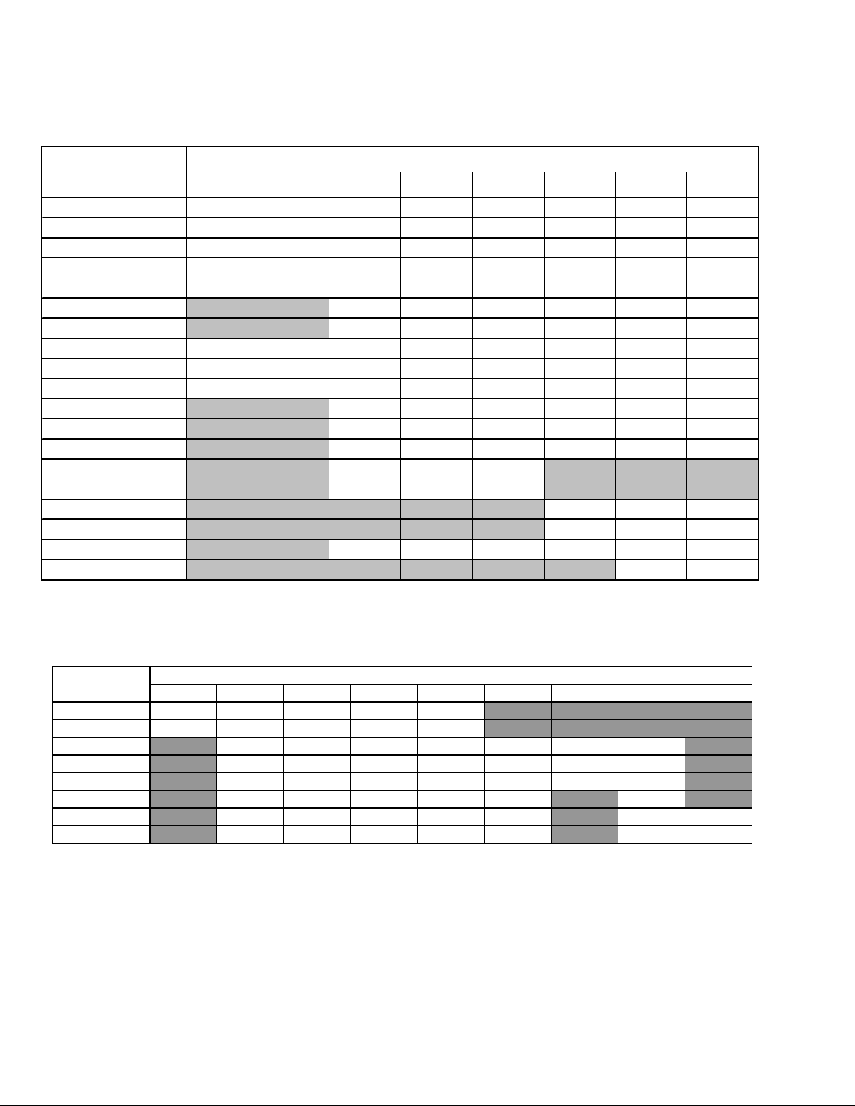
ACCESSORIES
ASPT**14**
Heat Kit Applications
TYPE/MODEL 24B14-A* 30C14-A* 36C14-A* 42C14-A* 48C14-A* 42D14-A* 48D14-A* 60D14-A*
HKSX03XC* XXXXXXXX
HKSX05XC* XXXXXXXX
HKSX06XC* XXXXXXXX
HKSX08XC* XXXXXXXX
HKSX10XC* XXXXXXXX
HKSX15XF* X X X X X X
HKSX20XF* X X X X X X
HKSC05 XC* X X X X X X X X
HKSC08 XC* X X X X X X X X
HKSC10 XC* X X X X X X X X
HKSC15 XA* X X X X X X
HKSC15 XB* X X X X X X
HKSC15 XF* X X X X X X
HKSC19 C A* X X X
HKSC19 C B* X X X
HKSC20 D A* XXX
HKSC20 D B* XXX
HKSC20 XF* X X X X X X
HKSC25 D C* XX
* Revision level that may or may not be designated.
Refer to the minimum airflow requirements for each of the heat kits.
ASPT
ASPT
ASPT24B14*
ASPT30C14*
3
715 715 71 5 71 5 875
730 715 71 5 71 5 950 NR NR
ASPT36C14* NR
ASPT42C14* NR
ASPT48C14* NR
ASPT42D14* NR
ASPT48D14* NR
ASPT60D14* NR
Minimum CFM required for Heater Kits
60
HEATER (kW)
5 6 8 10 15 19 20 25
NR NR NR NR
NR NR
1170 1170 1170 1170 1345 1345 1345
1170 1170 1170 1170 1345 1345 1345
1170 1170 1170 1170 1345 1345 1345 NR
1590 1590 1590 1590 1715 NR 1715 NR
1590 1590 1590 1590 1715 NR 1715 1715
1590 1590 1590 1590 1715 NR 1715 1715
NR
NR
Page 61
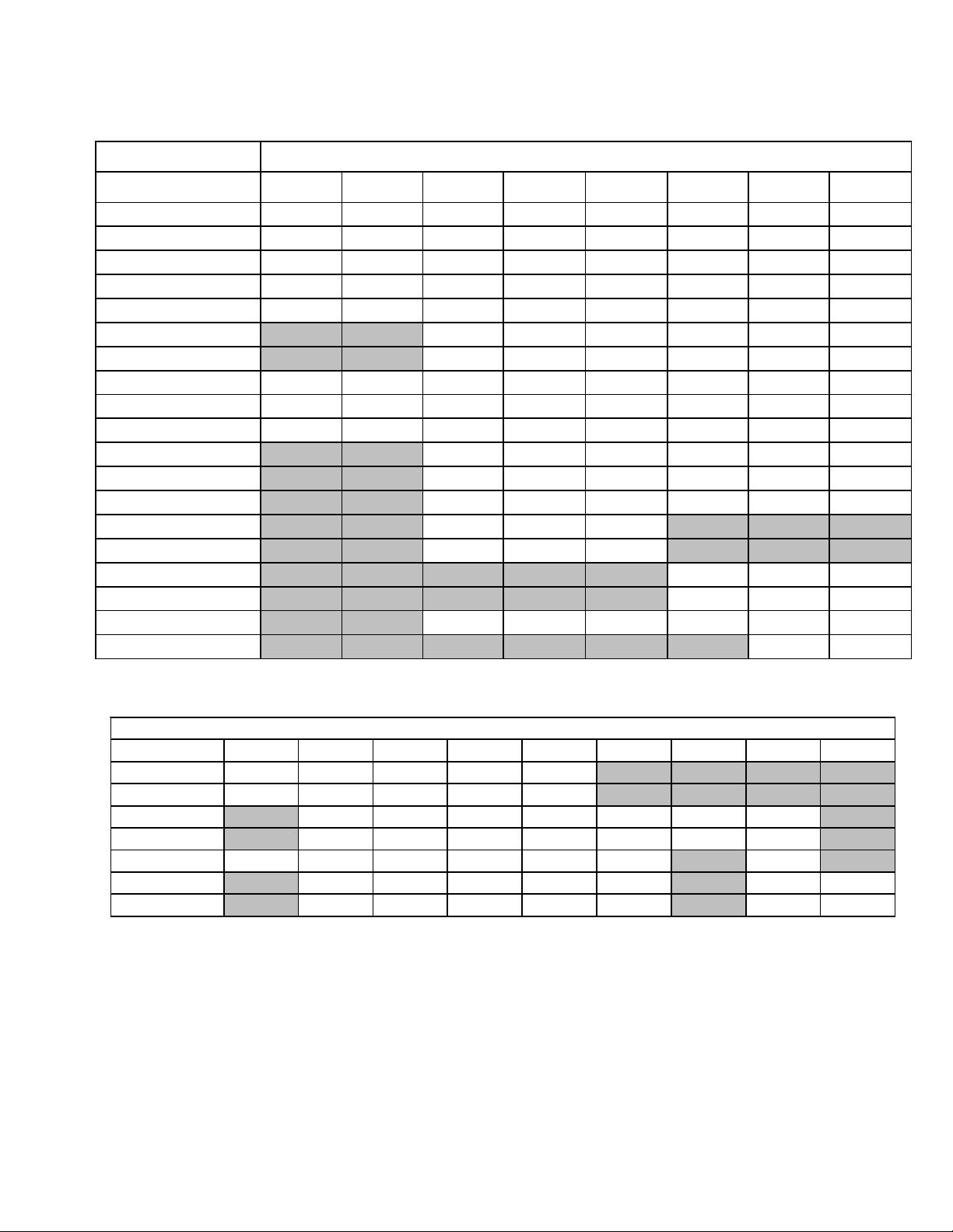
ACCESSORIES
AVPTC**14**
Heat Kit Applications
TYPE/MODEL 24B14-A* 30C14-A* 36C14-A* 42C14-A* 48C14-A* 42D14-A* 48D14-A* 60D14-A*
HKSX03XC* X X X X X X X X
HKSX05XC* X X X X X X X X
HKSX06XC* X X X X X X X X
HKSX08XC* X X X X X X X X
HKSX10XC* X X X X X X X X
HKSX15XF* X X X X X X
HKSX20XF* X X X X X X
HKSC05XC* X X X X X X X X
HKSC08XC* X X X X X X X X
HKSC10XC* X X X X X X X X
HKSC15XA* X X X X X X
HKSC15XB* X X X X X X
HKSC15XF* X X X X X X
HKSC19CA* X X X
HKSC19CB* X X X
HKSC20DA* XXX
HKSC20DB* XXX
HKSC20XF* X X X X X X
HKSC25DC* XX
* Revision level that may or may not be designated.
Refer to the minimum airflow requirements for each of the heat kits.
ASPT
Heater Kit (kW)
3 5 6 8 10 15 19 20 21 or 25
AVPTC24B14 550 650 700 800 850 NR NR NR NR
AVPTC30C14 60 0 7 00 750 875 950 NR NR NR NR
AVPTC36C14 NR 850 900 1000 1200 1440 1500 1500 NR
AVPTC48C14 NR 850 900 1000 1200 1440 1500 1500 NR
†
AVPTC42D14
AVPTC48D14
AVPTC60D14
Note: Airflow data shown applies to the electric heat only in either legacy mode or communicating mode operation
NR - Not rated
* Within thermostat user menu CTK0* communicating thermostat will di splay 20KW for OFF- OFF- ON dip switch selection, 21kW for
†For match up with a 2 ton outdoor unit: Heater kit application shall not exceed 10 kW.
Airflow for 5 kW up to 10 kW heater kits shall be set to 850 cfm speed tap of ON-ON-ON.
††For match up w ith a 3 ton outdoor unit: Heater kit application shall not exceed 15 kW.
Airflow for 5 kW up to 15 kW heater kits shall be set to 1300 cfm speed tap of ON-OFF-ON.
†††For match up w ith a 3.5 ton outdoor unit: Heater kit application shall not exceed 20 kW.
Airflow for 5 kW up to 20 kW heater kits shall be set to 1500 cfm speed tap of ON-OFF-OFF
** 3 kW heater kit is not applicable for this indoor application.
850** 1250 1300 1500 1550 1720 NR 1800 NR
††
†††
NR 1250 1300 1500 1550 1720 NR 1815 1850
NR 1250 1300 1500 1550 1780 NR 1850 1850
MINIMUM CF M REQUIRED F OR HEATER KITS , See notes below
61
Page 62

ACCESSORIES
ARUF & ASPT
MO DEL LI ST FOR DO WNFLO W KIT
DFK-B DFK-C DFK-D
DOWNFLOW KIT DOWNFLOW KIT DOWNFLOW KIT
ARUF25B14** ARUF37C14** ARUF37D14**
ARUF29B14** ARUF43C14** ARUF43D14**
ARUF31B14** ARUF49C14** ARUF47D14**
ASPT24B14** ASPT37C14**
ASPT29B14** ASPT47C14**
ASPT37B14** ASPT59C14**
ARUF49D14**
ARUF61D14**
ASPT61D14**
ASPT47D14**
ASPT49D14**
MODEL
3 5 6 8 10 15 19 20 25
ARUF25B14 715 715 715 715 950
ARUF29B14 715 715 715 715 950
ARUF31B14 715 715 715 715 875 875
ARUF37C14 1170 1170 1170 1170 1345 1345
ARUF43C14 1170 1170 1170 1170 1345 1345
ARUF49C14 1170 1170 1170 1170 1340 1430
ARUF37D14 1170 1170 1170 1170 1345 1345
ARUF43D14 1170 1170 1170 1170 1345 1345
ARUF47D14 1170 1170 1170 1170 1345 1345
ARUF49D14 1240 1240 1240 1240 1520 1520
ARUF61D14 1590 1590 1590 1590 1715 1715 1715
HEATER KI T (kW )
MI NIMUM CF M REQUIRED FO R HEAT ER KI T S
MODEL
ASPT24B14
ASPT29B14
ASPT37B14
ASPT37C14
ASPT47C14
ASPT59C14
ASPT47D14
ASPT49D14
ASPT61D14*
3 5 6 8 10 15 19 20 25
715 715 715 715 850
715 715 715 715 875 1050
715 715 715 715 875 1050
1170 1170 1170 1170 1345 1345
1170 1170 1170 1170 1345 1345
1170 1170 1170 1170 1345 1345
1240 1240 1240 1240 1520 1520
1590 1590 1590 1590 1715 1715 1715
1590 1590 1590 1590 1715 1715 1715
HEATER (kW)
62
Page 63

PRODUCT DESIGN
This section gives a basic description of cooling unit operation,
its various components and their basic operation. Ensure your
system is properly sized for heat gain and loss according to
methods of the Air Conditioning Contractors Association (ACCA)
or equivalent.
CONDENSING UNIT
The condenser air is pulled through the condenser coil by a direct
drive propeller fan. This condenser air is then discharged out of
the top of the cabinet. These units are designed for free air
discharge, so no additional resistance, like duct work, shall be
attached.
The suction and liquid line connections on present models are of
the sweat type for field piping with refrigerant type copper. Front
seating valves are factory installed to accept the field run copper.
The total refrigerant charge for a normal installation is factory
installed in the condensing unit.
GSX, GSZ, ASX, ASZ, SSX, SSZ, DSX, DSZ, VSX, and VSZ models are
available in 1 1/2 through 5 ton sizes and use R-410A refrigerant.
They are designed for 208/230 volt single phase applications.
GSX/GSZ *****3 models are available in 3, 4, and 5 ton sizes and
use R-410A refrigerant. They are designed for 208/230 volt 3phase applications.
ASX, ASZ, DSX and DSZ R-410A model units use the Copeland Scroll
"Ultratech" Series compressors which are specifically designed
for R-410A refrigerant. These units also have Copeland
ComfortAlert diagnostics.
GSX, GSZ, SSX, SSZ, VSX, and VSZ R-410A model units, except for
GSX130181C*, VSX130181B*, VSX130241E*, VSX130421B*, and
VSX130481B*, use the Copeland Scroll "Ultratech" Series compressors which are specifically designed for R-410A refrigerant.
There are a number of design characteristics which are different
from the traditional reciprocating and/or scroll compressors.
"Ultractech" Series scroll compressors will not have a discharge
thermostat. Some of the early model scroll compressors required
discharge thermostat.
"Ultratech" Series scroll compressors use "POE" or polyolester
oil which is NOT compatible with mineral oil based lubricants
like 3GS. "POE" oil must be used if additional oil is required.
The MBR blower cabinet uses a PSC motor. It is approved for
applications with cooling coils of up to 0.5 inches W.C. external
static pressure.
The MBR/MBE blower cabinets with proper coil matches can be
positioned for upflow, counterflow, horizontal right or horizontal left operation. All units are constructed with R-4.2 insulation.
In areas of extreme humidity (greater than 80% consistently),
insulate the exterior of the blower with insulation having a vapor
barrier equivalent to ductwork insulation, providing local codes
permit.
The CAUF, CAPF and CAPT coils are designed for upflow and
counterflow applications. The CACF and CHPF coils are designed
for horizontal applications.
AR*F, ASPF, ASUF, ASPT
Multi-Position Air Handler
These one-piece multi-position air handlers are used with R410A and are available in 2 to 5 ton sizes with optional 3 kW to
25kW electric heat kits available for field installation. The AR*F
unit’s blower design includes a PSC motor and is compatible with
heat pumps and cooling applications. ASUF and ASPT units use
an EEM blower motor and are compatible with heat pumps and
cooling applications.
This appliance can be installed in the vertical or left horizontal
position without modification. The horizontal right and downflow
positions require product modification. This product is designed
®
for zero inches (0 inches) clearance; however, adequate access
for service or replacement must be considered without removing
permanent structure. This unit can be installed on a platform
when deemed necessary.
In an attic installation a secondary drain pan must be provided
by the installer and placed under the entire unit with a separate
drain line properly sloped and terminated in an area visible to
the owner. This secondary drain pan is required in the event that
there is a leak or main drain blockage. Closed cell insulation
should be applied to the drain lines in unconditioned spaces
where sweating may occur.
NOTE: Single piece air handlers are factory-sealed to achieve a
2% or less leakage rate at 1.0" water gauge external duct static
pressure.
COILS AND BLOWER COILS
MBR/MBE blower cabinets are designed to be used as a two-piece
blower and coil combination. MBR/MBE/MBVC blower sections
can be attached to cased evaporator coil. This two-piece arrangement allows for a variety of mix-matching possibilities providing
greater flexibility. The MBE/MBVC blower cabinets use a variable
speed motor that maintains a constant airflow with a higher duct
static.
MBE blower cabinests are approved for applications with cooling coils of up to 0.8 inches W.C. external static pressure. The MBE
models includes a feature that allows airflow to be changed by
+10% or -15%. The MBVC models allow airflow trimming of +/10%.
63
Page 64

PRODUCT DESIGN
The ASX [16 & 18], ASZ [16 & 18], DSX[16 & 18] and DSZ [16 & 18]
series split system units use a two-stage scroll compressor. The
two-step modulator has an internal unloading mechanism that
opens a bypass port in the first compression pocket, effectively
reducing the displacement of the scroll. The opening and closing
of the bypass port is controlled by an internal electrically
operated solenoid.
The ZPS/ZRS two-step modulated scroll uses a single step of
unloading to go from full capacity to approximately 67% capacity. A single speed, high efficiency motor continues to run while
the scroll modulates between the two capacity steps.
FIGURE A
As this motion occurs, the pockets between the two forms are
slowly pushed to the center of the two scrolls while simultaneously being reduced in volume. When the pocket reaches the
center of the scroll form, the gas, which is now at a high pressure,
is discharged out of a port located at the center.
During compression, several pockets are being compressed
simultaneously, resulting in a very smooth process. Both the
suction process (outer portion of the scroll members) and the
discharge process (inner portion) are continuous.
Some design characteristics of the Compliant Scroll compressor
are:
• Compliant Scroll compressors are more tolerant of liquid
refrigerant.
NOTE: Even though the compressor section of a Scroll compressor is more tolerant of liquid refrigerant, continued
floodback or flooded start conditions may wash oil from the
bearing surfaces causing premature bearing failure.
• "Ultratech" Series scroll compressors use "POE" or polyolester
oil which is NOT compatible with mineral oil based lubricants like 3GS. "POE" oil must be used if additional oil is
required.
• Compliant scroll compressors perform "quiet" shutdowns
that allow the compressor to restart immediately without the
need for a time delay. This compressor will restart even if the
system has not equalized.
NOTE: Operating pressures and amp draws may differ from
standard reciprocating compressors. This information can
be found in the unit's Technical Information Manual.
A scroll is an involute spiral which, when matched with a mating
scroll form as shown, generates a series of crescent shaped gas
pockets between the two members.
During compression, one scroll remains stationary (fixed scroll)
while the other form (orbiting scroll) is allowed to orbit (but not
rotate) around the first form.
64
Page 65

PRODUCT DESIGN
c
CAPACITY CONTROL - LEGACY MODELS
During the compression process, there are several pockets within
the scroll that are compressing gas. Modulation is achieved by
venting a portion of the gas in the first suction pocket back to the
low side of the compressor thereby reducing the effective displacement of the compressor. See Figure A. Full capacity is
achieved by blocking these vents, increasing the displacement to
100%. A solenoid in the compressor, controlled by an external 24volt ac signal, moves the slider ring that covers and uncovers
these vents. The vent covers are arranged in such a manner that
the compressor operates somewhere around 67% capacity when
the solenoid is not energized and 100% capacity when the
solenoid is energized. The loading and unloading of the two step
scroll is done “on the fly” without shutting off the motor between
steps. See Figure B below. The unloaded mode default was chosen
for two reasons:
Molded Plug w/
Rectifier
24 Va
1. It is expected that the majority of run hours will be in the low
capacity, unloaded mode.
2. It allows a simple two-stage thermostat to control capacity
through the second stage in both cooling and possibly heating if desired.
UNLOADER SOLENOID
A nominal 24-volt direct current coil activates the internal
unloader solenoid. The input control circuit voltage must be 18
to 28 volt ac. The coil power requirement is 20 VA. The external
electrical connection is made with a molded plug assembly. This
plug is connected to the Comfort Alert™ or CoreSense™ Module
(dependent upon which module you are using) which contains a
full wave rectifier to supply direct current to the unloader coil.
C
R
Internal Unloader
Coil
FIGURE B
Line
Run Capacitor
S
Line
COOLING
The refrigerant used in the system is R-410A. It is a clear,
colorless, non-toxic and non-irritating liquid. R-410A is a 50:50
blend of R-32 and R-125. The boiling point at atmospheric
pressure is -62.9°F.
A few of the important principles that make the refrigeration cycle
possible are: heat always flows from a warmer to a cooler body.
Under lower pressure, a refrigerant will absorb heat and vaporize
at a low temperature. The vapors may be drawn off and condensed at a higher pressure and temperature to be used again.
The indoor evaporator coil functions to cool and dehumidify the
air conditioned spaces through the evaporative process taking
place within the coil tubes.
NOTE: The pressures and temperatures shown in the refrigerant
cycle illustrations on the following pages are for demonstration
purposes only. Actual temperatures and pressures are to be
obtained from the "Expanded Performance Chart".
Liquid refrigerant at condensing pressure and temperatures,
(270 psig and 122°F), leaves the outdoor condensing coil through
the drier and is metered into the indoor coil through the metering
device. As the cool, low pressure, saturated refrigerant enters the
tubes of the indoor coil, a portion of the liquid immediately
vaporizes. It continues to soak up heat and vaporizes as it
proceeds through the coil, cooling the indoor coil down to about
48°F.
Heat is continually being transferred to the cool fins and tubes
of the indoor evaporator coil by the warm system air. This
warming process causes the refrigerant to boil. The heat removed
from the air is carried off by the vapor.
As the vapor passes through the last tubes of the coil, it becomes
superheated. That is, it absorbs more heat than is necessary to
vaporize it. This is assurance that only dry gas will reach the
compressor. Liquid reaching the compressor can weaken or
break compressor valves.
The compressor increases the pressure of the gas, thus adding
more heat, and discharges hot, high pressure superheated gas
into the outdoor condenser coil.
In the condenser coil, the hot refrigerant gas, being warmer than
the outdoor air, first loses its superheat by heat transferred from
the gas through the tubes and fins of the coil. The refrigerant now
becomes saturated, part liquid, part vapor and then continues to
give up heat until it condenses to a liquid alone. Once the vapor
is fully liquefied, it continues to give up heat which subcools the
liquid, and it is ready to repeat the cycle.
65
Page 66

SYSTEM OPERATION
HEATING
The heating portion of the refrigeration cycle is similar to the
cooling cycle. By energizing the reversing valve solenoid coil, the
flow of the refrigerant is reversed. The indoor coil now becomes
the condenser coil, and the outdoor coil becomes the evaporator
coil.
The check valve at the indoor coil will open by the flow of
refrigerant letting the now condensed liquid refrigerant bypass
the indoor expansion device. The check valve at the outdoor coil
will be forced closed by the refrigerant flow, thereby utilizing the
outdoor expansion device.
The restrictor orifice used with the CA*F, CHPF and CH**FCB coils
will be forced onto a seat when running in the cooling cycle, only
allowing liquid refrigerant to pass through the orifice opening.
In the heating cycle, it will be forced off the seat allowing liquid
to flow around the restrictor. A check valve is not required in this
circuit.
COOLING CYCLE
For legacy room thermostat: When the room thermostat calls for
cool, the contacts of the room thermostat close making terminals R to Y1 & G (if thermostat calls for low stage cool), or R to
Y1, Y2 & G (if thermostat calls for high stage cool), the low voltage
circuit of the transformer is completed. Current now flows
through the magnetic holding coils of the compressor contactor
(CC) and fan relay (RFC). If thermostat calls for high stage cool,
the microprocessor on the UC board will also energize the
compressor high stage solenoid to run the compressor at full
capacity.
This draws in the normally open contact CC, starting the compressor and condenser fan motors in either low or high stage
depending on the thermostat’s demand. At the same time, contacts RFC close, starting the indoor fan motor.
When the thermostat is satisfied, it opens its contacts, breaking
the low voltage circuit, causing the compressor contactor and
indoor fan relay to open, shutting down the system.
If the room thermostat fan selector switch should be set on the
“on” position, then the indoor blower would run continuously
rather than cycling with the compressor.
GSZ, ASZ, SSZ, DSZ, and VSZ models energize the reversing valve
thorough the "O" circuit in the room thermostat. Therefore, the
reversing valve remains energized as long as the thermostat
subbase is in the cooling position. The only exception to this is
during defrost.
For heat pumps, during cooling cycle the reversing valve is
energized as the room thermostat closes “O” terminal to R and
the microprocessor on the UC board responds to such a condition by energizing the solenoid coil on the reversing valve.
DEFROST CYCLE
The defrosting of the outdoor coil is jointly controlled by the
defrost control board and the defrost thermostat.
Solid State Defrost Control
During operation the power to the circuit board is controlled by
a temperature sensor, which is clamped to a return bend (3/8"
coils) or a feeder tube (5 mm coils) entering the outdoor coil.
Defrost timing periods of 30, 60, or 90 minutes may be selected
by connecting the circuit board jumper to 30, 60, or 90 respectively. Accumulation of time for the timing period selected starts
when the sensor closes (approximately 31° F), and when the room
thermostat calls for heat. At the end of the timing period, the unit’s
defrost cycle will be initiated provided the sensor remains
closed. When the sensor opens (approximately 75° F), the defrost
cycle is terminated and the timing period is reset. If the defrost
cycle is not terminated due to the sensor temperature, a ten
minute override interrupts the unit’s defrost period. The new
upgraded defrost control has a 12 minute override interrupt.
HEATING CYCLE
The reversing valve on the GSZ, SSZ, ASZ and DSZ models is
energized in the cooling cycle through the "O" terminal on the
room thermostat.
These models have a 24 volt reversing valve coil. When the
thermostat selector switch is set in the cooling position, the "O"
terminal on the thermostat is energized all the time.
Care must be taken when selecting a room thermostat. Refer to the
installation instructions shipped with the product for approved
thermostats.
When the room thermostat calls for heat, the contacts of the
room thermostat close making terminals R to Y & G, the low
voltage circuit of the transformer is completed. Current now
flows through the magnetic holding coils of the compressor
contactor (CC) and fan relay (RFC).
This draws in the normally open contact CC, starting the compressor condenser fan motors. At the same time, contacts RFC
close, starting the indoor fan motor.
When the thermostat is satisfied, it opens its contacts, breaking
the low voltage circuit, causing the compressor contactor and
indoor fan relay to open, shutting down the system.
If the room thermostat fan selector switch should be set to the
“on” position, then the indoor blower would run continuously
rather than cycling with the compressor.
When the thermostat is satisfied, appropriate commands are
sent to the UC control. The compressor relay and outdoor fan
relay is de-energized. The compressor high stage solenoid
is de-energized if it was energized. The UC control sends an
appropriate command to the indoor unit to de-energize the
indoor blower motor.
66
Page 67

SYSTEM OPERATION
COOLING CYCLE
Reversing Va lve
(Energized)
Indoor
Coil
HEATING CYCLE
Outdoor
Coil
Accumulator
Thermostatic
Expansion
Valve
Bi-Flow
Filter Dryer
Check Valve
Indoor
Coil
Reversing Va lve
(De-Energized)
Outdoor
Coil
Accumulator
Thermostatic
Expansion
Valve
Bi-Flow
Filter Dryer
Check Valve
67
Page 68

SYSTEM OPERATION
EXPANSION VALVE/CHECK VALVE ASSEMBLY IN
COOLING OPERATION
Most expansion valves used in current Amana® Brand Heat Pump products
use an internally checked expansion valve.
This type of expansion valve does not require an external check valve as shown above.
However, the principle of operation is the same.
RESTRICTOR ORIFICE ASSEMBLY IN
COOLING OPERATION
EXPANSION VALVE/CHECK VALVE ASSEMBLY IN
HEATING OPERATION
RESTRICTOR ORIFICE ASSEMBLY IN
HEATING OPERATION
In the cooling mode, the orifice is pushed into its seat,
forcing refrigerant to flow through the metered hole in
the center of the orifice.
68
In the heating mode, the orifice moves back off its seat,
allowing refrigerant to flow unmetered around the
outside of the orifice.
Page 69

SYSTEM OPERATION
AFE18-60A CONTROL BOARD
DESCRIPTION
The AFE18 control is designed for use in heat pump applications
where the indoor coil is located above/downstream of a gas or
fossil fuel furnace. It will operate with single and two stage heat
pumps and single and two stage furnaces. The AFE18 control will
turn the heat pump unit off when the furnace is turned on. An antishort cycle feature is also incorporated which initiates a 3
minute timed off delay when the compressor goes off. On initial
power up or loss and restoration of power, this 3 minute timed
off delay will be initiated. The compressor won’t be allowed to
restart until the 3 minute off delay has expired. Also included is
a 5 second de-bounce feature on the “Y, E, W1 and O” thermostat
inputs. These thermostat inputs must be present for 5 seconds
before the AFE18 control will respond to it.
An optional outdoor thermostat, OT18-60A, can be used with the
AFE18 to switch from heat pump operation to furnace operation
below a specific ambient temperature setting, i.e. break even
temperature during heating. When used in this manner, the “Y”
heat demand is switched to the “W1” input to the furnace by the
outdoor thermostat and the furnace is used to satisfy the first
stage “Y” heat demand. On some controls, if the outdoor thermo-
stat fails closed in this position during the heating season, it will
turn on the furnace during the cooling season on a “Y” cooling
demand. In this situation, the furnace produces heat and
increases the indoor temperature thereby never satisfying the
cooling demand. The furnace will continue to operate and can
only be stopped by switching the thermostat to the off position
or removing power to the unit and then replacing the outdoor
thermostat. When the AFE18 receives a “Y” and “O” input from
the indoor thermostat, it recognizes this as a cooling demand
in the cooling mode. If the outdoor thermostat is stuck in the
closed position switching the “Y” demand to the “W1” furnace
input during the cooling mode as described above, the AFE18
won’t allow the furnace to operate. The outdoor thermostat will
have to be replaced to restore the unit to normal operation.
HIGH VOLTAGE!
Disconnect ALL power before servicing
or installing. Multiple power sources
may be present. Failure to do so may
cause property damage, personal injury
or death.
69
Page 70

TROUBLESHOOTING CHART
COOLING/HP ANALYSIS CHART
Com p laint
POSSIBLE CAUSE
DOTS IN ANALYSIS
GUIDE INDICATE
"POS SIBL E CAUSE"
Pow er Failure
Blow n Fuse
Unbalanced Power, 3PH
Loose Connection
Shorted or Broken Wires
Open Fan Overload
Faulty Thermostat
Faulty Transformer
Shorted or Open Capacitor
Internal Compress or Ov er load Open
Shorted or Grounded Compressor
Compre s sor Stuc k
Faulty Compressor Contactor
Faulty Fan Relay
Open Control Circuit
Low Voltage
Faulty Evap. Fan Motor
Shorted or Grounded Fan Motor
Improper Cooling Anticipator
Shortage of Refrigerant
Restricted Liquid Line
Open Element or Limit on Elec. Heater
Dirty Air Filter
Dirty Indoor Coil
Not enough air across Indoor Coil
Too much air across Indoor Coil
Overcharge of Refrigerant
Dirty Outdoor Coil
Noncondensibles
Recirculation of Conden sing Air
Infiltration of Outdoor Air
Improperly Lo cated Thermostat
Air Flow Unbalanced
System Undersiz e d
Broken Internal Parts
Broken Valves
Inefficient Compressor
Wrong Type Expansion Valve
Expansion Device Restricted
Oversized Expansion Valve
Undersized Expansion Valve
Expansion Valve Bulb Loose
Inoperative Expansion Valve
Loose Hold-dow n Bolts
Faulty Reversing Valve
Faulty Defrost Control
Faulty Defrost Thermostat
Flow rator Not Seating Properly
No Cooling
SYMPTOM
System will not start
Compressor will not start - fan runs
Comp. and Cond. Fan will not start
Evaporator fan will not start
Condenser fan will not start
Compressor runs - goes off on overload
Compressor cycles on overload
Unsatis facto r y
Cooling/Heating
System runs continuously - little cooling/htg
Too cool and then too warm
•
•••
•••
•••
••••••
••
••• •
••
•••••
•
••
•••
•••
•
•
•••
••
••
••
••
•• •• •
♦♦
••• •
••• •
••• •
•• •
•• •
••
•• •
•••
••
••
••
•• ••
•
••• • ••
••• • •• •
••
••• • •
•• •
•
•
• Cooling or Heating Cy cle (Heat Pump)
•••
System
Ope rating
Pressures
Not cool enough on warm days
Certain areas too cool, others too warm
Compressor is noisy
System runs - blows cold air in heating
Unit will not terminate defrost
Unit will not defrost
Low suction pressure
Low head pressure
High suction pressure
High head pressure
♦
♦
♦
♦
♦
♦
♦
•
♦
••
♦
♦
••
♦
♦
♦
•
••
•
•
♦
••
•
♦♦♦ ♦♦♦
♦♦♦♦♦ ♦
♦♦♦♦♦♦♦
Heating Cycle Only (Heat Pump)
♦
Test Method
Re medy
See Service Procedure Ref.
Test Voltage S-1
Inspect Fuse Size & Type S-1
Test Voltage S-1
Ins pe ct Connection - Tighten S-2, S-3
Test Circuits With Ohmmeter S-2, S-3
Test Continuity of Overload S-17A
Test Continuity of Thermostat & Wiring S-3
Check Control Circuit w ith Voltmeter S-4
Test Capacitor S-15
Test Continuity of Overload S-17A
Test Motor Windings S-17B
Use Tes t Cord S-17D
Test Continuity of Coil & Contacts S-7, S-8
Test Continuity of Coil And Contacts S-7
Test Control Circuit w ith Voltmeter S- 4
Test Voltage S-1
Repair or Replace S-16
Test Motor Windings S-16
Check Resistance of Anticipator S-3B
Test For Leaks, Add Refrigerant S-101,103
Remove Restriction, Replace Restricted Part S-112
Test Heater Element and Controls S-26,S-27
Inspect Filter-Clean or Replace
Inspect Coil - Clean
Check Blower Speed, Duct Static Press, Filter S-200
Reduce Blow er Spe ed S-200
Recov er Part of Charge S-113
Inspect Coil - Clean
Recov er Charge, Evacuate, Recharge S-114
Remove Obstruction to Air Flow
Check Window s , Doors, Vent Fans , Etc.
Relocate Thermostat
Readjust Air Volume Dampers
Refigure Cooling Load
Replace Compresso r S-115
Test Compressor Efficiency S-104
Test Compressor Efficiency S-104
Replace V alv e S-110
Remove Restriction or Replace Expansion Device S-110
Replace V alv e
Replace V alv e
Tighten Bulb Bracket S-105
Check Valve Operation S-110
Tigh ten B olts
Replace Valve or Solenoid S-21, 122
Test Contro l S-24
Test Defros t Thermostat S-25
Check Flow r ator & Seat or Replace Flow rator S-111
70
Page 71

SERVICING
TABLE OF CONTENTS
SERVICING ...........................................................................71
S-1 CHECKING VOLT AGE.............................................72
S-2 CHECKING WIRING ............................................... 72
S-3 CHECKING THERMOSTA T AND WIRING ..............72
S-3A THERMOSTAT WIRING........................................... 72
S-4 CHECKING TRANSFORMER AND CONTROL
CIRCUIT..................................................................73
S-7 CHECKING CONTACTOR AND/OR RELAYS .........73
S-8 CHECKING CONTACT OR CONTACTS..................73
S-9 CHECKING FAN RELA Y CONT ACTS ..................... 74
S-10 MBR/AR*F ELECTRONIC
BLOWER TIME DELAY RELAY............................75
S-11 CHECKING LOSS OF CHARGE PROTECTOR.....75
S-12 CHECKING HIGH PRESSURE CONTROL ........... 75
S-13 CHECKING LOW PRESSURE CONTROL............75
S-10 COPELAND COMFORT ALER T™ ..........................76
S-10B COPELAND CORESENSE™................................. 76
S-15 CHECKING CAP ACITOR ........................................82
S-15A RESISTANCE CHECK USING A DIGIT AL MUL TI-
METER ....................................................................82
S-15B CAPACITANCE CHECK USING A DIGIT AL
MUL TI-METER (IN CAP ACIT ANCE MODE) .........82
S-16A CHECKING FAN AND BLOWER
MOTOR WINDINGS (PSC MOTORS) .................83
S-16B CHECKING F AN AND BLOWER MOTOR
(ECM MOTORS) ..................................................83
S-16C CHECKING ECM MOTOR WINDINGS ...................84
S-16D ECM CFM ADJUSTMENTS MBE / AEPF .................84
S-16E BLOWER PERFORMANCE DA TA...........................88
S-16F CHECKING HIGH EFFICIENCY MOTORS.............88
S-16G EEM BLOWER REPLACEMENT ............................89
S-17 CHECKING COMPRESSOR ..................................90
S-17A RESISTANCE TEST ................................................91
S-17B GROUND TEST ...................................................... 91
S-17C UNLOADER TEST PROCEDURE..........................91
S-17D OPERATION TEST ..................................................92
S-17E CHECKING 3-PHASE SCROLL COMPRESSOR
ROTATION.....................................................................92
S-18 TESTING CRANKCASE HEA TER
(OPTIONAL ITEM)................................................93
S-21 CHECKING REVERSING V AL V E
AND SOLENOID..................................................93
S-24 TESTING DEFROST CONTROL
S-25 TESTING DEFROST THERMOSTAT ......................93
S-50 CHECKING HEATER LIMIT CONTROL(S).............99
S-52 CHECKING HEA TER ELEMENTS..........................99
S-60 ELECTRIC HEA TER (OPTIONAL ITEM).................99
S-61A CHECKING HEATER LIMIT CONTROL(S)...........100
S-61B CHECKING HEATER FUSE LINK ........................100
(OPTIONAL ELECTRIC HEA TERS)......................100
S-62 CHECKING HEA TER ELEMENTS........................101
S-100 REFRIGERATION REP AIR PRACTICE ................101
S-101 LEAK TESTING
(NITROGEN OR NITROGEN-TRACED).............101
S-102 EVACUATION ........................................................101
S-103 CHARGING ...........................................................102
S-104 CHECKING COMPRESSOR EFFICIENCY ..........103
S-106 OVERFEEDING.....................................................104
S-107 UNDERFEEDING .................................................104
S-108 SUPERHEAT.........................................................104
S-109 CHECKING SUBCOOLING ..................................107
S-1 10 CHECKING EXP ANSION V AL VE OPERA TION.........107
S-112 CHECKING RESTRICTED LIQUID LINE.............107
S-113 OVERCHARGE OF REFRIGERANT .....................107
S-114 NON-CONDENSABLES .......................................108
S-115 COMPRESSOR BURNOUT .................................108
S-120 REFRIGERANT PIPING........................................109
S-201 CLEANING ALUMINUM COILS ................................109
S-202 DUCT STATIC PRESSURES
AND/OR ST A TIC PRESSURE DROP
ACROSS COILS ................................................109
S-203 SINGLE PIECE AIR HANDLER
EXTERNAL ST A TIC............................................109
S-203A TWO PIECE AIR HANDLER
EXTERNAL ST A TIC PRESSURE ......................109
S-204 COIL ST ATIC PRESSURE DROP.........................110
............................93
HIGH VOLT AGE!
Disconnect ALL power before servicing or installing. Multi ple power sources may be present. Failure to
do so may cause pr operty damage, personal injury or death.
71
Page 72

SERVICING
S-1 CHECKING VOLTAGE
1. Remove outer case, control panel cover, etc., from unit being
tested.
With power ON:
WARNING
Line Voltage now present.
2. Using a voltmeter, measure the voltage across terminals L1
and L2 of the contactor for the condensing unit or at the field
connections for the air handler or heaters.
3. No reading - indicates open wiring, open fuse(s) no power or
etc., from unit to fused disconnect service. Repair as needed.
4. With ample voltage at line voltage connectors, energize the
unit.
5. Measure the voltage with the unit starting and operating, and
determine the unit Locked Rotor Voltage. NOTE: If checking
heaters, be sure all heating elements are energized.
Locked Rotor Voltage is the actual voltage available at the
compressor during starting, locked rotor, or a stalled condition. Measured voltage should be above minimum listed in
chart below.
To measure Locked Rotor Voltage attach a voltmeter to the run
"R" and common "C" terminals of the compressor, or to the T
and T2 terminals of the contactor. Start the unit and allow the
compressor to run for several seconds, then shut down the
unit. Immediately attempt to restart the unit while measuring
the Locked Rotor Voltage.
6. Locked rotor voltage should read within the voltage tabulation as shown. If the voltage falls below the minimum voltage,
check the line wire size. Long runs of undersized wire can
cause low voltage. If wire size is adequate, notify the local
power company in regard to either low or high voltage.
Unit Supply Voltage
Voltag e Min. Max
208/230 197 253
460 414 506
S-2 CHECKING WIRING
HIGH VOLTAGE!
Disconnect ALL power before servicing
or installing. Multiple power sources
may be pr es ent. Fa ilur e t o do s o ma y
cause pro pe rty dam age , pe rs onal in jury
or death.
1. Check wiring visually for signs of overheating, damaged
insulation and loose connections.
2. Use an ohmmeter to check continuity of any suspected open
wires.
3. If any wires must be replaced, replace with comparable gauge
and insulation thickness.
S-3 CHECKING THERMOSTAT AND WIRING
Thermostat Wiring: The maximum wire length for 18 AWG thermostat wire is 100 feet.
S-3A THERMOSTAT WIRING
WARNING
Line Voltage now present.
1
With power ON, thermostat calling for cooling
1. Use a voltmeter to check for 24 volts at thermostat wires C and
Y in the condensing unit control panel.
2. No voltage indicates trouble in the thermostat, wiring or
external transformer source.
3. Check the continuity of the thermostat and wiring. Repair or
replace as necessary.
Indoor Blower Motor
With power ON:
WARNING
Line Voltage now present.
NOTE: When operating electric heaters on voltages other than
240 volts, refer to the System Operation section on electric
heaters to calculate temperature rise and air flow. Low voltage
may cause insufficient heating.
72
1. Set fan selector switch at thermostat to "ON" position.
2. With voltmeter, check for 24 volts at wires C and G.
3. No voltage indicates the trouble is in the thermostat or wiring.
4. Check the continuity of the thermostat and wiring. Repair or
replace as necessary.
Resistance Heaters
1. Set room thermostat to a higher setting than room temperature so both stages call for heat.
2. With voltmeter, check for 24 volts at each heater relay.
Page 73

SERVICING
3. No voltage indicates the trouble is in the thermostat or wiring.
4. Check the continuity of the thermostat and wiring. Repair or
replace as necessary.
NOTE: Consideration must be given to how the heaters are wired
(O.D.T. and etc.). Also safety devices must be checked for continuity.
S-4 CHECKING TRANSFORMER AND CONTROL CIRCUIT
HIGH VOLTAGE!
Disconnect ALL power before servicing
or installing. Multiple power sources
may be present. Failure to do so may
cause property damage, personal injury
or death.
A step-down transformer (208/240 volt primary to 24 volt secondary) is provided with each indoor unit. This allows ample
capacity for use with resistance heaters. The outdoor sections
do not contain a transformer (see note below).
WARNING
Disconnect ALL power before servicing.
1. Remove control panel cover, or etc., to gain access to transformer.
With power ON:
WARNING
Line Voltage now present.
2. Using a voltmeter, check voltage across secondary voltage
side of transformer (R to C).
3. No voltage indicates faulty transformer, bad wiring, or bad
splices.
4. Check transformer primary voltage at incoming line voltage
connections and/or splices.
5 If line voltage available at primary voltage side of trans-
former and wiring and splices good, transformer is inoperative. Replace.
S-7 CHECKING CONTACTOR AND/OR RELAYS
HIGH VOLT AGE!
Disconnect ALL power before servicing
or installing. Multiple power sources
may be present. Failure to do so may
cause property damage, personal injury
or death.
The compressor contactor and other relay holding coils are
wired into the low or line voltage circuits. When the control
circuit is energized, the coil pulls in the normally open contacts
or opens the normally closed contacts. When the coil is deenergized, springs return the contacts to their normal position.
NOTE: Most single phase contactors break only one side of the
line (L1), leaving 115 volts to ground present at most internal
components.
NOTE: The compressor contactor/relay in ComfortNet
ready equipment is fully integrated into the unitary (UC) control. The compressor contactor/relay coil on the UC control
is non-serviceable.
1. Remove the leads from the holding coil.
2. Using an ohmmeter, test across the coil terminals.
If the coil does not test continuous, replace the relay or contactor.
TM
S-8 CHECKING CONTACTOR CONTACTS
WARNING
Disconnect ALL power before servicing.
SINGLE PHASE:
1. Disconnect the wire leads from the terminal (T) side of the
contactor.
2. With power ON, energize the contactor.
WARNING
Line V oltage now present.
3. Using a voltmeter, test across terminals.
A. L2 - T1 - No voltage indicates CC1 contacts open.
If a no voltage reading is obtained - replace the contactor.
73
Page 74

SERVICING
T2
VOLT/OHM
METER
Ohmmeter for testing holding co il
Voltmete r f o r te st in g con ta cts
TESTING COMPRESSOR CONTACTOR
(Single Phase)
THREE PHASE
Using a voltmeter, test across terminals:
A . L1-L2, L1-L3, and L2-L3 - If voltage is present, proceed to
B. If voltage is not present, check breaker or fuses on
main power supply..
B. T1-T2, T1-T3, and T2-T3 - If voltage readings are not the
same as in "A", replace contactor.
T1
CC
L1L2
T3L3T2
T1
1. Disconnect wire leads from terminals 2 and 4 of Fan Relay
Cooling and 2 and 4, 5 and 6 of Fan Relay Heating.
2. Using an ohmmeter, test between 2 and 4 - should read open.
Test between 5 and 6 - should read continuous.
3. With power ON, energize the relays.
WARNING
Line Voltage now present.
4
OHMMETER
2
5
TESTING FAN RELAY
4. Using an ohmmeter, test between 2 and 4 - should read
continuous . Test between 5 and 6 - should read open.
5. If not as above, replace the relay.
CHECKING RELAY CONTACTS - PSC FAN MOTOR
3
1
CC
VOLT/OHM
METER
Ohmmeter for testing holding co il
Voltmeter for testing contacts
TESTING COMPRESSOR CONTACTOR
(Three-Phase)
S-9 CHECKING FAN RELAY CONTACTS
HIGH VOLT AGE!
Disconnect ALL power before servicing
or installing. Multiple power sources
may be present. Failure to do so may
cause property damage, personal injury
or death.
L2
L1
HIGH VOLT AGE!
Disconnect ALL power before servicing
or installing. Multiple power sources
may be present. Failure to do so may
cause property damage, personal injury
or death.
1. Disconnect the motor leads from 6-circuit fan motor wire
harness.
2. Connect a voltmeter between circuit 3 and circuits 2 (low
speed) or 1 (high speed).
NOTE: Circuit 3 is connected directly to L2.
3. Energize the system at low or high stage.
WARNING
Line V oltage now present.
4. The measured voltage between circuit 3 and circuits 2 or 1
should be approximately 0VAC, which indicates the relay
contacts are closed. A voltage measurement of approximately 115VAC indicates the relay is open. Replace the
control if the relay checks open when it should be closed. See
notes and cautions below.
74
Page 75

SERVICING
NOTE: Ensure any ON delays have expired before making
voltage measurements
CAUTION: Prolonged operation with the condenser fan motor
disconnected will cause the high pressure switch to trip.
S-10 MBR/AR*F ELECTRONIC BLOWER TIME DELAY
RELAY
The MBR/AR*F contains an Electronic Blower Time Delay Relay
board, B1370735. This board provides on/off time delays for the
blower motor in cooling and heat pump heating demands when
“G” is energized.
During a cooling or heat pump heating demand, 24Vac is
supplied to terminal “G” of the EBTDR to turn on the blower
motor. The EBTDR initiates a 7 second delay on and then
energizes it’s onboard relay. The relay on the EBTDR board
closes it’s normally open contacts and supplies power to the
blower motor. When the “G” input is removed, the EBTDR
initiates a 65 second delay off. When the 65 seconds delay
expires the onboard relay is de-energized and it’s contacts open
and remove power from the blower motor.
During an electric heat only demand, “W1” is energized but “G”
is not. The blower motor is connected to the normally closed
contacts of the relay on the EBTDR board. The other side of this
set of contacts is connected to the heat sequencer on the heater
assembly that provides power to the first heater element. When
“W1” is energized, the sequencer will close it’s contacts within
10 to 20 seconds to supply power to the first heater element and
to the blower motor through the normally closed contacts on the
relay on the EBTDR. When the “W1” demand is removed, the
sequencer opens it contacts within 30 to 70 seconds and
removes power from the heater element and the blower motor.
The EBTDR also contains a speedup terminal to reduce the delays
during troubleshooting of the unit. When this terminal is
shorted to the common terminal, “C”, on the EBTDR board, the
delay ON time is reduced to 3 seconds and the delay OFF time
is reduced to 5 second.
Two additional terminals, M1 and M2, are on the EBTDR board.
These terminals are used to connect the unused leads from the
blower motor and have no affect on the board’s operation.
S-12 CHECKING HIGH PRESSURE CONTROL
HIGH VOL TAGE!
Disconnect ALL power before servicing
or installing. Multiple power sources
may be present. Failure to do so may
cause pr ope rty dam age , pe rs onal inju ry
or death.
The high pressure control capillary senses the pressure in the
compressor discharge line. If abnormally high condensing
pressures develop, the contacts of the control open, breaking the
control circuit before the compressor motor overloads. This
control is automatically reset.
1. Using an ohmmeter, check across terminals of high pressure
control, with wire removed. If not continuous, the contacts
are open.
2. Attach a gauge to the dill valve port on the base valve.
With power ON:
WARNING
Line Voltage now present.
3. Start the system and place a piece of cardboard in front of the
condenser coil, raising the condensing pressure.
4. Check pressure at which the high pressure control cuts-out.
If it cuts-out at 610 PSIG ± 10 PSIG, it is operating normally
(See causes for high head pressure in Service Problem Analysis Guide). If it cuts out below this pressure range, replace
the control.
S-11 CHECKING LOSS OF CHARGE PROTECTOR
(Heat Pump Models)
The loss of charge protectors senses the pressure in the liquid
line and will open its contacts on a drop in pressure. the low
pressure control will automatically reset itself with a rise in
pressure.
The low pressure control is designed to cut-out (open) at
approximately 21 PSIG. It will automatically cut-in (close) at
approximately 50 PSIG.Test for continuity using a VOM and if
not as above, replace the control.
S-13 CHECKING LOW PRESSURE CONTROL
The low pressure control senses the pressure in the suction line
and will open its contacts on a drop in pressure. The low pressure
control will automatically reset itself with a rise in pressure.
The low pressure control is designed to cut-out (open) at approximately 21 PSIG for heat pumps and 55 PSIG for air conditioners.
It will automatically cut-in (close) at approximately 50 PSIG for
heat pumps and 95 PSIG for air conditioners.
Test for continuity using a VOM and if not as above, replace the
control.
75
Page 76

SERVICING
S-10 COPELAND COMFORT ALERT™
DIAGNOSTICS - 3-WIRE MODULE
Applies to ASX /ASZ and DSX/DSZ units
Comfort Alert™ is self-contained with no required external sensors and is designed to install directly into the electrical box of
any residential condensing unit that has a Copeland Scroll™
compressor inside.
Once attached, Comfort Alert provides around-the-clock monitoring for common electrical problems, compressor defects and
broad system faults. If a glitch is detected, an LED indicator
flashes the proper alert codes to help you quickly pinpoint the
problem. See Diagnostic Table: 3-Wire Comfort Alert Module on
previous page.)
S-10BCOPELAND CORESENSE™
DIAGNOSTICS - 3-WIRE MODULE
Applies to ASX /ASZ and DSX/DSZ units
Bold line shows field
installed wiring
Dashed line shows thermostat
demand wiring in system without
HTCO, HPCO, CPCO, and ECB
Comfort Alert
Diagnostics Module
HTCO High Temperature Cut Out Switch
HPCO High Pressure Cut Out Switch
LPCO Low Pressure Cut Out Switch
Y
C
R
Schematic Abbreviation Descriptions
CC
ECB
HTCO
LOGIC
R
CC Compressor Contactor
ECB Electronic C ontrol Board
(Defrost or Time Delay)
Wiring Schematic - 3-Wire Comfort Alert Module
LPCO
C
HPCO
HIGH VOL TAGE!
Disconnect ALL power before servicing
or installing. Multiple power sources
may be present. Failure to do so may
cause pr ope rty dam age , pe rs onal inju ry
or death.
The CoreSense™ module is self-contained with no required exter-
Y1
nal sensors and works with any residential condensing unit that
has a Copeland Scroll™ compressor inside.
Once attached, CoreSense™ provides around-the-clock monitoring for common electrical problems, compressor defects and
broad system faults. If a glitch is detected, an LED indicator
flashes the proper alert codes to help you quickly pinpoint the
problem. See Diagnostic Table: 3-Wire CoreSense™ Module on
following pages.)
76
Page 77

SERVICING
DIAGNOSTICS TABLE: 2-WIRE COMFORT ALERT™ MODULE
Status LED Status LED Description S tatus LED Troubleshooting Information
Gree n “ P OWER” Modu le h a s powe r
Re d “ T RI P ”
Yellow “ALERT” Long Run Tim e
Flash Code 1
Yellow “ALERT” System Pressure Trip
Flash Code 2
Yellow “ALERT” Short Cycling
Flash Code 3
Yellow “ALERT” Locked Rotor
Flash Code 4
Yellow “ALERT” Ope n Circuit
Flash Code 5
Yellow “ALERT” Ope n Start Circuit
Flash Code 6
Yellow “ALERT” Ope n Run Circuit
Flash Code 7
Yellow “ALERT” Low Voltage
Flash Code 9
Thermost at dem and s igna l 1. Com p ressor protect or is open
Y1 is present, but the 2. Outdoor unit power disconnect is open
com pres s o r is not 3. Com pres s or c irc uit break er or fuse(s) is open
running 4. Brok en wi re or connec t or is not m ak ing c ont ac t
Compress or is 2. Evaporator blower is not running
running ex t rem ely 3. E vaporator coil i s froze n
long run cycles 4. F ault y m et ering device
Disc harge or suction 2. Condenser coil poor air circulation (dirty, bloc k ed, dam aged)
press ure out of limit s or 3. Condens e r fan is not runnin g
com pressor overloaded 4. Return air duct has subs tantial leak age
Compres s o r is running 2. Time delay relay or c ont rol board defect ive
only briefly 3. If high press ure s wit c h pres ent go to Flas h Code 2 informat ion
Current only in run c irc uit 2. O pen c irc uit in c om pres s or s t art wiring or c onnec t ions
Current only in s t art c irc uit 2. Com pres s or run winding is dam ag ed
Control c irc uit < 1 7V A C 2. Low line voltage (cont ac t ut ili ty if voltage at dis c o nnec t i s low)
Suppl y voltage is present at m odu le t erm in als
5. Low pressure switc h open if present in sy s tem
6. Com pres s or c ont ac tor has failed open
1. Low refrigerant c harge
5. Condenser coil is dirty
6. Liquid line res tric t ion (filter drier bloc k ed if present in s y s t em )
7. Thermos t at is m al funct ioning
1. High head press ure
5. If low press ure switc h present in s ys t em,
c heck Flash Code 1 information
1. Thermostat demand signal is intermittent
4. If low pressure s wit c h pres ent go to F las h Cod e 1 informati on
1. Run capacitor has failed
2. Low line voltage (c ont ac t uti lit y i f voltage at dis c onnec t is low)
3. E x c es s ive liquid refrigerant in com pres s or
4. Com pres s or bearings are s eiz ed
1. Out door unit power dis c onn ec t is op en
2. Com pres s or c irc uit break er or fuse(s ) is open
3. Com pres s or c ont ac tor has failed open
4. High pres s ure s wit c h is open an d requires m anual res et
5. Ope n c ircui t in c om pres s or sup ply wiring or c onnec t ions
6. Unus ual ly long c om pres s or prot ec tor res et tim e
due t o e x t rem e ambient t em perat ure
7. Com pres s or windings are dam age d
1. Run capacitor has failed
3. Com pres s or s tart winding is dam a ged
1. Ope n c ircui t in c om pres s or run wiring or conne c tions
1. Control circuit transformer is overloaded
• FLASH CODE NUMBER CORRESPONDS TO A NUMBER OF LED FLASHES, FOLLOWED BY A P AUSE AND THEN REPEA TED
• TRIP AND ALERT LEDS FLASHING A T SAME TIME MEANS CONTROL CIRCUIT VOL T AGE IS TOO LOW FOR OPERATION.
• LAST ALERT FLASH CODE IS DISPLA YED FOR 1 MINUTE AFTER MODULE IS POWERED ON.
77
Page 78

SERVICING
Once attached, CoreSense™ provides around-the-clock monitoring for common electrical problems, compressor defects and
broad system faults. If a glitch is detected, an LED indicator
flashes the proper alert codes to help you quickly pinpoint the
problem. See Diagnostic Table: 2-Wire Comfort Alert™ Module on
following pages.)
Indoor
Unit
HTCO High Temperature Cut Out Switch
HPC O High P r essur e Cut Out Swit ch
LPCO Low Pressure Cut Out Switch
C
Y
Schematic Abbreviation Descriptio ns
CC Compressor Contactor
ECB Electronic Control Board
(Defrost or Time Delay)
Wiring Schematic - 3-Wire CoreSense™ Alert Module
Reset
Switch
Run/Alert
LED
Trip/Lock-Out
Red LED
Protection
Output
Data Port
One
Current
Sensor
Schematic Abbreviation Descriptions
HTCO High Temperature Cut Out Switch
HPCO High Pressure Cut Out Switch
LPCO Low Pressur e Cut Out Switch
CC Compressor Contactor
ECB Electronic Control Board
Wiring Schematic - 2-Wire CoreSense™ Module
(Defrost or Time Delay)
DIAGNOSTICS - 2-WIRE MODULE
Applies to ASX130[18-60]CA, ASX140[18-36]1CA,
ASX140421DA, and ASX140[48-60]1BA units
HIGH VOL TAGE!
Disconnect ALL power before servicing
or installing. Multiple power sources
may be present. Failure to do so may
cause pr ope rty dam age , pe rs onal inju ry
or death.
The CoreSense™ module is self-contained with no required external sensors and works with any residential condensing unit that
has a Copeland Scroll™ compressor inside.
78
Page 79

SERVICING
DIAGNOSTICS TABLE: CORESENSE
Flash code number corresponds to the number of LED flashes, followed by a pause and then repeated.
TRIP and ALERT LEDs flashing at the same time mean control circuit voltage is too low for operation.
™ MODULE
79
Page 80

SERVICING
DIAGNOSTICS TABLE: CORESENSE™ MODULE (CONT.)
Flash code number corresponds to the number of LED flashes, followed by a pause and then repeated.
TRIP and ALERT LEDs flashing at the same time mean control circuit voltage is too low for operation.
80
Page 81

SERVICING
Table 1 - Quick Reference Table
81
Page 82

SERVICING
S-15 CHECKING CAPACITOR
CAPACITOR, RUN
A run capacitor is wired across the auxiliary and main windings
of a single phase permanent split capacitor motor. The capacitors primary function is to reduce the line current while greatly
improving the torque characteristics of a motor. This is accomplished by using the 90° phase relationship between the capacitor current and voltage in conjunction with the motor windings,
so that the motor will give two phase operation when connected
to a single phase circuit. The capacitor also reduces the line
current to the motor by improving the power factor.
The line side of this capacitor is marked with "COM" and is wired
to the line side of the circuit.
CAPACITOR, START
SCROLL COMPRESSOR MODELS
In most cases hard start components are not required on Scroll
compressor equipped units due to a non-replaceable check valve
located in the discharge line of the compressor. However, in
installations that encounter low lock rotor voltage, a hard start
kit can improve starting characteristics and reduce light dimming within the home. Only hard start kits approved by Amana
brand or Copeland should be used. "Kick Start" and/or "Super
Boost" kits are not approved start assist devices.
The discharge check valve closes off high side pressure to the
compressor after shut down allowing equalization through the
scroll flanks. Equalization requires only about 1/2 second.
To prevent the compressor from short cycling, a Time Delay
Relay (Cycle Protector) has been added to the low voltabe
circuit.
S-15A RESISTANCE CHECK USING A DIGITAL MULTI-
METER
Figure 1 Figure 2
4. Reading will immediately return to the OL = (Open Line)
(Figure 2). Every attempt of Step 2 will show the same result
®
as was in step 4 and Step 5. This indicates that the capacitor
is good.
5. If there is no Change, then capacitor is dead and must be
replaced.
Check for Analog Meter
A. Good Condition - indicator swings to zero and slowly
returns to infinity. (Start capacitor with bleed resistor will
not return to infinity. It will still read the resistance of the
resistor).
B. Shorted - indicator swings to zero and stops there - replace.
C. Open - no reading - replace. (Start capacitor would read
resistor resistance.)
HIGH VOLT AGE!
Disconnect ALL power before servicing
or installing. Multiple power sources
may be present. Failure to do so may
cause property damage, personal injury
or death.
Check for Digital Test
1. Set the meter on Ohm range (Set it at lease 1000 Ohm
=1k).
WARNING
Discharge capacitor through a 20 to 30 OHM
resistor before han dling.
2. Connect the Meter leads to the Capacitor terminals.
3. Digital meter will show a reading momentarily (Figure 1).
Note the reading.
82
S-15BCAPACITANCE CHECK USING A DIGITAL MULTI-
METER (IN CAPACITANCE MODE)
WARNING
Discharge capacitor through a 20 to 30 OHM
resistor before handling.
NOTE: You can do this test with a multi-meter if you have a
Capacitance meter on your multi-meter.
1. Remove the capacitor from the circuit.
2. Now Select "Capacitance" on your multi-meter.
3. Now connect the capacitor terminals to the multi-meter
leads.
4. If the reading is near to the actual value of the capacitor (i.e.
the printed value on the capacitor). The capacitor is good.
(Note that the reading may be less than the actual printed
value of the capacitor).
5. If you read a significantly lower capacitance or none at all,
then capacitor is dead and must be replaced.
Page 83

SERVICING
A
S-16A CHECKING FAN AND BLOWER MOTOR WINDINGS
(PSC MOTORS)
The auto reset fan motor overload is designed to protect the motor
against high temperature and high amperage conditions by
breaking the common circuit within the motor, similar to the
compressor internal overload. However, heat generated within
the motor is faster to dissipate than the compressor, allow at
least 45 minutes for the overload to reset, then retest.
5. If line voltage is present, reinsert the 5-pin connector and
remove the 16-pin connector.
6. Check for signal (24 volts) at the transformer.
7. Check for signal (24 volts) from the thermostat to the "G"
terminal at the 16-pin connector.
8. Using an ohmmeter, check for continuity from the #1 & #3
(common pins) to the transformer neutral or "C" thermostat
terminal. If you do not have continuity, the motor may
function erratically. Trace the common circuits, locate and
repair the open neutral.
HIGH VOLTAGE!
Disconnect ALL power before servicing
or installing. Multiple power sources
may be present. Failure to do so may
cause property damage, personal injury
or death.
9. Set the thermostat to "Fan-On". Using a voltmeter, check for
24 volts between pin # 15 (G) and common.
10. Disconnect power to compressor. Set thermostat to call for
cooling. Using a voltmeter, check for 24 volts at pin # 6 and/
or #14.
11. Set the thermostat to a call for heating. Using a voltmeter,
check for 24 volts at pin #2 and/or #11.
1. Remove the motor leads from its respective connection points
and capacitor (if applicable).
2. Check the continuity between each of the motor leads.
3. Touch one probe of the ohmmeter to the motor frame (ground)
and the other probe in turn to each lead.
If the windings do not test continuous or a reading is obtained
from lead to ground, replace the motor.
S-16BCHECKING FAN AND BLOWER MOTOR (ECM
MOTORS)
1
2
3
4
5
Lines 1 and 2 will be connected
for 12OVAC Power Connector
}
applications only
Gnd
AC Line Connection
AC Line Connection
An ECM is an Electronically Commutated Motor which offers many
significant advantages over PSC motors. The ECM has near zero
rotor loss, synchronous machine operation, variable speed, low
noise, and programmable air flow. Because of the sophisticated
electronics within the ECM motor, some technicians are intimated by the ECM motor; however, these fears are unfounded. GE
offers two ECM motor testers, and with a VOM meter, one can
easily perform basic troubleshooting on ECM motors. An ECM
OUT - OUT +
DJUST +/-
Y1 Y/Y2
816
7
15
6
14
G (FAN)
motor requires power (line voltage) and a signal (24 volts) to
operate. The ECM motor stator contains permanent magnet. As a
result, the shaft feels "rough" when turned by hand. This is a
characteristic of the motor, not an indication of defective bear-
COOL
DELAY
5
13
EM Ht/W2
4
12
24 Vac (R)
ings.
3
11
COMMON2
WARNING
Line Voltage now present.
1. Disconnect the 5-pin connector from the motor.
2. Using a volt meter, check for line voltage at terminals #4 & #5
W/W1
COMMON1 O (REV VALVE)
16-PIN ECM HARNESS CONNECTOR
2
19
HEAT
10
BK/PWM (SPEED)
at the power connector. If no voltage is present:
3. Check the unit for incoming power See section S-1.
4. Check the control board, See section S-40.
If you do not read voltage and continuity as described, the
problem is in the control or interface board, but not the motor.
If you register voltage as described , the ECM power head is
defective and must be replaced.
83
Page 84

SERVICING
S-16CCHECKING ECM MOTOR WINDINGS
HIGH VOLT AGE!
Disconnect ALL power before servicing
or installing. Multiple power sources
may be present. Failure to do so may
cause property damage, personal injury
or death.
1. Disconnect the 5-pin and the 16-pin connectors from the ECM
power head.
2. Remove the 2 screws securing the ECM power head and
separate it from the motor.
3. Disconnect the 3-pin motor connector from the power head
and lay it aside.
4. Using an ohmmeter, check the motor windings for continuity
to ground (pins to motor shell). If the ohmmeter indicates
continuity to ground, the motor is defective and must be
replaced.
5. Using an ohmmeter, check the windings for continuity (pin
to pin). If no continuity is indicated, the thermal limit (over
load) device may be open. Allow motor to cool and retest.
3-pin motor
connector
16-pin
connector
For most applications, the settings are to be changed according
to the electric heat size and the outdoor unit selection.
The MBE/AEPF products use a General Electric ECMTM motor. This
motor provides many features not available on the traditional
PSC motor. These features include:
• Improved Efficiency
• Constant CFM
• Soft Start and Stop
• Improved Humidity Control
MOTOR SPEED ADJUSTMENT
Each ECM™ blower motor has been preprogrammed for operation
at 4 distinct airflow levels when operating in Cooling/Heat Pump
mode or Electric Heat mode. These 4 distinct levels may also be
adjusted slightly lower or higher if desired. The adjustment
between levels and the trim adjustments are made by changing
the dipswitch(s) either to an "OFF" or "ON" position.
DIPSWITCH FUNCTIONS
The MBE / AEPF air handler motors have an electronic control that
contains an eight (8) position dip switch. The function of these
dipswitches are shown in Table 1.
Dipswitch Functions
Dipswitch
Number
1
2
3N/A
4 Indoor Thermostat
5Cooling & Heat
6 Pump CFM
7
8
Function
El ectric Heat
CFM Tr i m A djus t
Table 1
5-pin
connector
S-16DECM CFM ADJUSTMENTS MBE / AEPF
MBE MOTOR
This section references the operation characteristics of the MBE/
AEPF models motor only. The ECM control board is factory set
with the dipswitch #4 in the “ON” position and all other dipswitches
are factory set in the “OFF” position. When MBE/AEPF are used
with 2-stage cooling units, dipswitch #4 should be in the "OFF"
position.
84
CFM DELIVERY
Tables 2, 3, 5 and 6 show the CFM output for dipswitch combinations 1-2, and 5-6.
Electric Heat Operation
Model Switch 1 Switch 2 CFM
MBE1200
OFF
ON
OFF
OFF
OFF
ON
1,200
1,000
800
ON ON 600
MBE1600
OFF
ON
OFF
OFF
OFF
ON
1,600
1,400
1,200
ON ON 1,000
MBE2000
OFF
OFF
ON OFF 1,800
OFF ON 1,600
2,000
ON ON 1,200
Table 2
Page 85

SERVICING
Cooling/H eat Pump Operation
Model S w itch 5 Swi t c h 6 CFM
1,200
1,000
800
1,600
1,400
1,200
2,000
1,800
1,600
MBE1200
MBE1600
MBE2000
OFF
ON
OFF
ON ON 600
OFF
ON
OFF
ON ON 1,000
OFF
ON
OFF
ON ON 1,200
OFF
OFF
ON
OFF
OFF
ON
OFF
OFF
ON
Table 3
THERMOSTA T “FAN ONL Y” MODE
During Fan Only Operations, the CFM output is 30% of the cooling
setting.
Dipswitch Functions
The AEPF air handler motor has an electronic control that contains an eight (8) position dip switch. The function of these
dipswitches are shown in Table 9.
Di p switch Number F un ctio n
1
2
3N/A
4 Indoor Thermostat
5
6
7
8
Table 9
Electric Heat
Cooling & Heat Pump CF M
CFM Trim A dju st
Model
AEPF1830
AEPF3036
AEPF3137
AEPF4260
Switch Switch
1278
OFF OFF OFF OFF 1100 12 10
ON OFF OFF OFF 8 9 0 9 35
OFF ON OFF OFF 700 7 7 0
OFF OFF OFF OFF 2050 2150
ON OFF OFF OFF 175 0 1835
OFF ON OFF OFF 1 600 1680
ON ON OFF OFF 1200 1260
ON ON OFF ON 1020 1070
Emergecny
(Elec tric)
Heat
Heat Pump
w/Backup
Heat
Table 10
Model
AEPF183
0
AEPF3036 ON OFF OFF OFF 4 1580
AEPF3137 OFF O N OF F OFF 3 ½ 1480
AEPF4260 ON ON OFF OFF 3 1200
Switch Switch
5678
OFF OFF OFF OFF 2 ½ 1100
ON OFF OFF OFF 2 800
OFF ON OFF OFF 1 ½ 600
OFF OFF OFF OFF 5 1800
ON ON OFF ON 2 ½ 1020
Nominal
Cooling
Tonnage
CFM
Table 11
Thermostat “Fan Only Mode”
During “Fan Only Mode” operation, the CFM output is 30% of the
cooling setting.
CFM Trim Adjust
Minor adjustments can be made through the dip switch combination of 7-8. The following Table 12 shows the switch position
for this feature.
CFM Delivery
Tables 10-Electric Heat and 11-Cooling/Heat Pump show the CFM
output for dipswitch combinations 1-2, and 5-6.
CFM Swi tch 7 Switch 8
+10% ON OFF
-15% OFF ON
Humidity Control
When using a Humidistat (normally closed), cut jumper PJ6 on the
control board. The Humidistat will only affect cooling airflow by
adjusting the Airflow to 85%.
85
Page 86

SERVICING
(
y
)
g
I
d
t
d
i
l
gg
d?
Ch
k
f
l
i
fl
(t
h
l
t
t
ity)
Check
for
undercharged
condition
Check
and
plug
leaks
in
return
ducts
cabinet
I
t
t
N
t
U
i
g
th
g
t
/
t
l
d
l
id
ll
d
t
ti
d
y
d
t
d
lt
y
y
g
g
g
y
y
y
different
86
have completel
- Turn power OFF prior to repair.
Wait 5 minutes after
disconnecting pow er before
opening motor.
- Handle electronic motor/control w ith car e.
- Turn power OFF prior to repair.
Wait 5 minutes after
disconnecting pow er before
opening motor.
- Handle electronic motor/control w ith car e.
- Check 230 V ac power at motor.
- Check lo w voltage (24 V ac R to C) at mo tor.
- Check low voltage connections
(G, Y , W, R, C) at motor.
- Check fo r unseated pins in connector s
on motor harness.
- Test w ith a temporary jumper betw een R - G.
-
- Check fo r loos e motor mount.
- Make sure blow er w heel is tight on shaft.
- Perform motor/control replacement check,
ECM motors only .
- Turn power OFF prior to repair.
- Check line voltage f o r variation or "s ag ".
- Check low voltage connections
(G, Y , W, R, C) at
motor, unseated pins in motor
harness connec tors .
- Check-out system controls - Thermostat.
- Perform Moisture Check.*
- Turn power OFF prior to repair.
.
.
capac
look alike, different modules ma
,
en
a
h the
oo muc
ow
r
modes. Even thou
ow a
or
e harnesses with "dr i p loop" under motor.
ec
-
- Does removing panel or f ilter
reduc e "pu ffing"?
- Check/replace filter.
- Check/correct duct restrictions.
- Adjust to correct blower speed setting.
s.
resu
e
uce unexpec
rammed for specific operatin
pro
pro
ma
.- Arran
---- ---- ----
---- ---- ----
es an
are factor
CHART CONTINUED ON NEXT PAGE
warran
uc
pro
s a
- Manual disc on nect sw itch off or
door s w itch open.
- Blown f use or circ uit breaker.
- 24 Vac w ires misw ired.
- Unseated pins in wiring
harnes s connec tor s.
- Bad motor/control module.
- Moisture present in motor or control module.
- Loos e motor mount.
- Blow er w heel not tight on motor sha ft.
- Bad motor/control module.
- V ariation in 230 Vac to motor.
- Unseated pins in w iring harnes s
connectors.
- Erratic CFM co mmand f rom
"BK" terminal.
- Improper thermostat c on nection or setting.
- Moisture present in motor/control module.
- Incorrect or dirty filter(s ).
- Incorrect supply or retur n du ctwork.
- Incorrect blow er speed setting.
equipment manufacturer
e vo
u
mo
ro
con
or
. -
or as recommended b
Troubleshooting Chart for GE/Regal-Beloit ECM Variable Speed Air Circulator Blower Motors
- This is normal star t- up for
variable speed motor.
- No move ment.
- Motor rocks,
but w on't s ta rt.
- It is normal for motor to
oscillate w ith
no load on shaf t.
- Varies up and down
or intermittent.
- "Hunts" or "puffs" at
high CFM (spe ed).
e
u
n p
ra
e
ensa
Symptom Fault Description(s) Possible Causes Corrective Action Cautions and Notes
- Motor rocks
slightly
w hen s tarting.
- Motor won't
sta rt.
- Motor
oscillates up &
dow n w hile
being tested
off of blow er .
- Motor starts,
but runs
err atically.
s con
-
*Moisture Check
- Connectors a re oriented "down"
mo
e wron
n
s
e:
o
an
You must use the correct replacement control/motor module since the
mpor
functionality. The ECM variable speed motors are c
-
Note:
Page 87

SERVICING
(
y
)
g
I
d
t
d
i
l
gg
d?
Ch
k
f
l
i
fl
(t
h
l
t
t
ity)
Check
for
undercharged
condition
Check
and
plug
leaks
in
return
ducts
cabinet
I
t
t
N
t
U
i
g
th
g
t
/
t
l
d
l
id
ll
d
t
ti
d
y
d
t
d
lt
y
y
g
g
g
y
y
y
different
have completel
- Turn power OFF prior to repair.
Wait 5 minutes after
disconnecting pow er before
opening motor.
- Handle electr onic motor/con trol
w ith care.
- Turn power OFF prior to repair.
Wait 5 minutes after
disconnecting pow er before
opening motor.
- Handle electr onic motor/con trol
w ith care.
- Turn power OFF prior to repair.
- Check low voltage (Thermostat)
w ires a nd connections.
- V e r ify fan is not in delay mode -
w ait until delay complete.
- Perform motor/control replacement
check, ECM motors only.
- Is fan in delay mode? - w ait until delay time
complete.
- Perform motor/control replacement check, ECM
motors only.
- Check for Triac sw itched t'stat
or solid state relay.
CHART CONTINUED FROM PREVIOUS PAGE.
- 24 Vac wires miswired or loose.
- "R" miss ing/not con nected at motor.
- Fan in delay mode.
Troubleshooting Chart f or GE/Regal-Beloi t ECM Variable Speed Air Circul ator Blower Motors
- S tays a t low CFM d espite
system call for cool
or heat CFM.
Symptom Fault Description(s) Possible Cause s Corrective Action Cautions and No tes
- "R" miss ing/not con nected at motor.
- Fan in delay mode.
- Stays at high CFM.
- Motor starts,
but runs
erratic ally.
- Current leakage from controls
into G, Y, or W.
- Blow er w on't shut off.
- Turn power OFF prior to repair.
- Check/replace filter.
- Check/correct duct restrictions.
- Adjust to correct blow er speed setting.
- Turn power OFF prior to repair.
- Check fo r loos e blow er housing,
panels, etc.
- Check fo r air w histling thru seams in
ducts, cabinets or panels.
- Check fo r cabinet/duc t deformation.
- Turn power OFF prior to repair.
- Does removing panel or f ilter
reduc e "p uffing"?
- Check/replace filter.
- Turn power OFF prior to repair.
Wait 5 minutes after
disconnecting pow er before
opening motor.
- Handle electr onic motor/con trol
w ith care.
.
.
capac
look alike, different modules ma
,
en
a
h the
oo muc
ow
r
modes. Even thou
ow a
or
e harnesses with "drip loop" under motor.
ec
-
- Check/correct duct restrictions.
- Adjust to correct blow er speed setting.
- Replace motor and perf orm
Moisture Chec k.*
s.
resu
e
uce unexpec
rammed for specific operatin
pro
pro
ma
.- Arran
es an
are factor
warran
uc
pro
s a
- High s tatic creating high blow er speed.
- Incorrect supply or return ductwork.
- Incorrect or dirty f ilter(s).
- Incorrec t blower speed setting.
- Loos e blow e r ho using, panels, etc .
- High s tatic creating high blow er
speed.
- Air leaks in ductwork, cabinets,
or panels.
- High s tatic creating high blow er speed.
- Incorrect or dirty f ilter(s).
- Incorrect supply or return ductwork.
- Incorrec t blower speed setting.
- Moisture in motor/control module.
equipment manufacturer
e vo
u
mo
ro
con
or
. -
or as recommended b
e
- Air noise.
- Noisy blower or cabinet.
- "Hunts" or "puffs" at
high CFM (s pee d) .
- Motor failure or
malfunction has
occ u r red and moisture
is present.
u
n p
ra
e
ensa
s con
*Moisture Check
-
- Evidence of
- Excessive
noise.
Moistur e.
- Connectors are oriented "down"
mo
e wron
n
s
e:
o
an
You must use the correct replacement control/motor module since the
mpor
-
functionality. The ECM variable speed motors are c
Note:
87
Page 88

SERVICING
S-16EBLOWER PERFORMANCE DATA
SPE ED STATIC
0.1 1,240 1,500 1,800 2,160
0.2 1,170 1,460 1,740 2,080
HIGH
MEDIUM
LOW
NOTE: External static is for blower @ 230 Volts. It does not include Coil, Air Filter or Electric Heaters.
0.3 1,120 1,360 1,680 1,990
0.4 1,060 1,280 1,610 1,890
0.5 980 1,200 1,520 1,790
0.6 900 1,110 1,430 1,690
0.1 900 1,380 1,540 1,730
0.2 850 1,320 1,490 1,670
0.3 790 1,270 1,450 1,590
0.4 740 1,200 1,400 1,520
0.5 680 1,140 13,560 1,420
0.6 605 1,040 1,280 1,320
0.1 650 1,170 1,130 1,520
0.2 590 1,130 1,100 1,450
0.3 540 1,080 1,070 1,360
0.4 500 1,020 1,030 1,290
0.5 430 950 990 1,200
0.6 330 830 930 1,090
MBR800**-*
SCFM
MBR1200**-*
SCFM
MBR1600**-*
SCFM
MBR2000**-*
SCFM
S-16F CHECKING HIGH EFFICIENCY MOTORS
The motor is a one piece, fully encapsulated, 3 phase brushless
DC (single phase AC input) motor with ball bearing construction.
1. Using a voltmeter, check for 230 volts to the motor connections L and N. If 230 volts is present, proceed to step 2. If 230
volts is not present, check the line voltage circuit to the motor.
2. Using a voltmeter, check for 24 volts from terminal C to either
terminal 1, 2, 3, 4, or 5, depending on which tap is being used,
at the motor. If voltage present, proceed tostep 3. If no voltage,
check 24 volt circuit to motor.
3. If voltage was present in steps 1 and 2, the motor has failed
and will need to be replaced.
NOTE: When replacing motor, ensure the belly band is
between the vents on the motor and the wiring has the proper
drip loop to prevent condensate from entering the motor.
High Voltage
Connections
3/16"
C
123
LGN
4
5
Low Voltage Connections
1/4”
MOTOR CONNECTIONS
88
Page 89

SERVICING
S-16G EEM BLOWER REPLACEMENT
For AWUF19-25, AWUF31-32, and AWUF37 Air Handlers.
1. Disconnect power at main electrical panel.
2. Remove front access panel.
3. Remove the two screws on each side holding the lower control
box and move out of the way to give access to the blower
assembly
6. Install cardboard or rug over coil to protect fins from damage.
5. Loosen or remove set screw on blower wheel hub and ensure
the wheel slides freely on the shaft of the motor.
7. Remove the three 3/8" screws holding the blower in place.
8. Lower blower onto coil.
9. Slide blower assembly all the way to the left side of cabinet.
89
Page 90

SERVICING
10. Remove the bolts holding the motor bracket to the blower and
slide out of blower shell.
S-17 CHECKING COMPRESSOR
WARNING
Hermetic compressor electrical terminal venting can
be dangerous. When insulating mat erial whic h
supports a hermeti c compresso r or electr ical t erminal
suddenly disintegrates due to physical abuse or as a
result of an electrical short between the terminal and
the compressor housing, the terminal may be
expelled, venting the vapor an d liquid contents of the
compres sor ho us ing an d sy stem .
If the compressor terminal PROTECTIVE COVER and gasket (if
required) are not properly in place and secured, there is a remote
possibility if a terminal vents, that the vaporous and liquid
discharge can be ignited, spouting flames several feet, causing
potentially severe or fatal injury to anyone in its path.
This discharge can be ignited external to the compressor if the
terminal cover is not properly in place and if the discharge
impinges on a sufficient heat source.
Ignition of the discharge can also occur at the venting terminal
or inside the compressor, if there is sufficient contaminant air
present in the system and an electrical arc occurs as the terminal
vents.
Ignition cannot occur at the venting terminal without the presence of contaminant air, and cannot occur externally from the
venting terminal without the presence of an external ignition
source.
Therefore, proper evacuation of a hermetic system is essential
at the time of manufacture and during servicing.
To reduce the possibility of external ignition, all open flame,
electrical power, and other heat sources should be extinguished
or turned off prior to servicing a system.
11. Replace the motor and reinstall blower and control box.
12. Reconnect power and test operation.
90
Page 91

SERVICING
S-17ARESISTANCE TEST
Each compressor is equipped with an internal overload.
The line break internal overload senses both motor amperage
and winding temperature. High motor temperature or amperage
heats the disc causing it to open, breaking the common circuit
within the compressor on single phase units.
Heat generated within the compressor shell, usually due to
recycling of the motor, high amperage or insufficient gas to cool
the motor, is slow to dissipate. Allow at least three to four hours
for it to cool and reset, then retest.
Fuse, circuit breaker, ground fault protective device, etc. has not
tripped -
HIGH VOLTAGE!
Disconnect ALL power before servicing
or installing. Multiple power sources
may be present. Failure to do so may
cause property damage, personal injury
or death.
1. Remove the leads from the compressor terminals.
WARNING
Hermetic compressor electrical terminal venting can
be dangerous. When insulating mat erial whic h
supports a hermeti c compresso r or electr ical t erminal
suddenly disintegrates due to physical abuse or as a
result of an electrical short between the terminal and
the compressor housing, the terminal may be
expelled, venting the vapor an d liquid contents of the
compres sor ho us ing an d sy stem .
S-17BGROUND TEST
If fuse, circuit breaker, ground fault protective device, etc., has
tripped, this is a strong indication that an electrical problem
exists and must be found and corrected. The circuit protective
device rating must be checked, and its maximum rating should
coincide with that marked on the equipment nameplate.
With the terminal protective cover in place, it is acceptable to
replace the fuse or reset the circuit breaker ONE TIME ONLY to see
if it was just a nuisance opening. If it opens again,
continue to reset.
Disconnect all power to unit, making sure that
open.
1. DO NOT remove protective terminal cover. Disconnect the
three leads going to the compressor terminals at the nearest
point to the compressor.
2. Identify the leads and using an ohmmeter on the R x 10,000
scale or the highest resistance scale on your ohmmeter check
the resistance between each of the three leads separately to
ground (such as an unpainted tube on the compressor).
3. If a ground is indicated, then carefully remove the compressor terminal protective cover and inspect for loose leads or
insulation breaks in the lead wires.
4. If no visual problems indicated, carefully remove the leads
at the compressor terminals.
5. Carefully retest for ground, directly between compressor
terminals and ground.
6. If ground is indicated, replace the compressor. The resistance
reading should be infinity. If there is any reading on meter,
there is some continuity to ground and compressor should
be considered defective.
all power legs are
DO NOT
2. Using an ohmmeter, test continuity between terminals S-R, CR, and C-S, on single phase units or terminals T2, T2 and T3,
on 3 phase units.
C
OHMMETER
TESTING COMPRESSOR WINDINGS
If either winding does not test continuous, replace the compressor.
NOTE: If an open compressor is indicated, allow ample time for
the internal overload to reset before replacing compressor.
S
COMP
R
OHMMETER
WARNING
Damage can occur to the glass embedded terminals if
the leads are not pro perly removed. This can result in
terminal and hot oil discharging.
S-17CUNLOADER TEST PROCEDURE
A nominal 24-volt direct current coil activates the internal
unloader solenoid. The input control circuit voltage must be 18
to 28 volt ac. The coil power requirement is 20 VA. The external
electrical connection is made with a molded plug assembly. This
plug contains a full wave rectifier to supply direct current to the
unloader coil.
91
Page 92

SERVICING
Y
UNLOADER SOL E NOID
Unloader Test Procedure
If it is suspected that the unloader is not working, the following
methods may be used to verify operation.
1. Operate the system and measure compressor current. Cycle
the unloader ON and OFF at 10 second intervals. The compressor amperage should go up or down at least 25 percent.
2. If step one does not give the expected results, shut unit off.
Apply 18 to 28 volt ac to the unloader molded plug leads and
listen for a click as the solenoid pulls in. Remove power and
listen for another click as the unloader returns to its original
position.
3. If clicks can’t be heard, shut off power and remove the control
circuit molded plug from the compressor and measure the
unloader coil resistance. The resistance should be 32 to 60
ohms, depending on compressor temperature.
4. Next check the molded plug.
A . Voltage check: Apply control voltage to the plug wires
(18 to 28 volt ac). The measured dc voltage at the
female connectors in the plug should be around 15 to
27 vdc.
B. Resistance check: Measure the resistance from the
end of one molded plug lead to either of the two female
connectors in the plug. One of the connectors should
read close to zero ohms while the other should read
infinity. Repeat with other wire. The same female
connector as before should read zero while the other
connector again reads infinity. Reverse polarity on
the ohmmeter leads and repeat. The female connector
that read infinity previously should now read close to
zero ohms.
C. Replace plug if either of these test methods doesn’t
show the desired results.
S-17DOPERATION TEST
If the voltage, capacitor, overload and motor winding test fail to
show the cause for failure:
(Molded Plug)
HIGH VOLT AGE!
Disconnect ALL power before servicing
or installing. Multiple power sources
may be present. Failure to do so may
cause property damage, personal injury
or death.
1. Remove unit wiring from disconnect switch and wire a test
cord to the disconnect switch.
NOTE: The wire size of the test cord must equal the line wire size
and the fuse must be of the proper size and type.
2. With the protective terminal cover in place, use the three
leads to the compressor terminals that were disconnected at
the nearest point to the compressor and connect the common,
start and run clips to the respective leads.
3. Connect good capacitors of the right MFD and voltage rating
into the circuit as shown.
4. With power ON, close the switch.
WARNING
Line Voltage now present.
A . If the compressor starts and continues to run, the cause for
failure is somewhere else in the system.
B. If the compressor fails to start - replace.
COPELAND COMPRESSOR
03 A 12345 L
EAR
S-17E CHECKING 3-PHASE SCROLL COMPRESSOR
ROTATION
Verify the proper rotation of Copeland scroll compressors as
follows:
NOTE: The compressor may run backwards (noisy operation)
for 1 or 2 seconds at shutdown. This is normal and does not
harm the compressor.
1. Install gauges and verify that the suction pressure drops
while the discharge pressure increases.
2. Listen for normal compressor sound levels. Reverse rotation
results in elevated or unusual sound levels.
3. Reverse rotation will result in substantially reduced amp
draw from tabulated values.
To correct improper rotation, switch any two power supply leads
at the outdoor unit contactor.
MONTH
SERIAL
NUMBER
PLANT
92
Page 93
SERVICING
The 3-phase scroll compressors are direction of rotation
sensitive. They will rotate in either direction depending on
the phasing of the power. There is no negative impact on
durability caused by operating 3-phase compressors in
reversed rotation. The compressor's internal protector will
trip, de-energizing the compressor. Continued operation of
3-phase scroll compressors with the rotation reversed will
contribute to compressor failure. All 3-phase scroll compressors should be checked for correct phase rotation.
S-18 TESTING CRANKCASE HEATER (OPTIONAL ITEM)
The crankcase heater must be energized a minimum of four (4)
hours before the condensing unit is operated.
Crankcase heaters are used to prevent migration or accumulation of refrigerant in the compressor crankcase during the off
cycles and prevents liquid slugging or oil pumping on start up.
A crankcase heater will not prevent compressor damage due to a
floodback or over charge condition.
WARNING
Disconnect ALL power before servicing.
1. Disconnect the heater lead in wires.
2. Using an ohmmeter, check heater continuity - should test
continuous. If not, replace.
NOTE: The positive temperature coefficient crankcase heater is
a 40 watt 265 voltage heater. The cool resistance of the heater
will be approximately 1800 ohms. The resistance will become
greater as the temperature of the compressor shell increases.
S-21 CHECKING REVERSING VALVE AND SOLENOID
Occasionally the reversing valve may stick in the heating or
cooling position or in the mid-position.
When stuck in the mid-position, part of the discharge gas from
the compressor is directed back to the suction side, resulting in
excessively high suction pressure. An increase in the suction
line temperature through the reversing valve can also be measured. Check operation of the valve by starting the system and
switching the operation from COOLING to HEATING cycle.
If the valve fails to change its position, test the voltage (24V) at
the valve coil terminals, while the system is on the COOLING
cycle.
If no voltage is registered at the coil terminals, check the
operation of the thermostat and the continuity of the connecting
wiring from the "O" terminal of the thermostat to the unit.
S-24 TESTING DEFROST CONTROL
To check the defrost control for proper sequencing, proceed as
follows: With power ON; unit not running.
1. Jumper defrost thermostat by placing a jumper wire across
the terminals "DFT" and "R"/"R-DFT" at defrost control
board.
2. Connect jumper across test pins on defrost control board.
3. Set thermostat to call for heating. System should go into
defrost within 21 seconds.
4. Immediately remove jumper from test pins.
5. Using VOM check for voltage across terminals "C & O". Meter
should read 24 volts.
6. Using VOM check for voltage across fan terminals DF1 and
DF2 on the board. You should read line voltage (208-230 VAC)
indicating the relay is open in the defrost mode.
7. Using VOM check for voltage across "W"/"W2" & "C" terminals on the board. You should read 24 volts.
8. If not as above, replace control board.
9. Set thermostat to off position and disconnect power before
removing any jumpers or wires.
NOTE: Remove jumper across defrost thermostat before
returning system to service.
S-25 TESTING DEFROST THERMOSTAT
1. Install a thermocouple type temperature test lead on the tube
adjacent to the defrost control. Insulate the lead point of
contact.
2. Check the temperature at which the control closes its contacts by lowering the temperature of the control. Part #
0130M00009P which is used on 2 and 2.5 ton units should
close at 34°F ± 5°F. Part # 0130M00001P or B1370803 which
is used on 3 thru 5 ton units should close at 31°F ± 3°F.
3. Check the temperature at which the control closes its contacts by lowering the temperature of the control. Part #
0130M00085, which is used onunits with 5 mm coils, should
close at 30°F ± 5°F.
4. Check the temperature at which the control opens its contacts
by raising the temperature of the control. Part #0130M00009P
which is used on 2 and 2.5 ton units should open at 60°F ± 5°F.
Part # 0130M00001P or B1370803 which is used on 3 thru
5 ton units should open at 75°F ± 6°F.
5. Check the temperature at which the control opens its contacts
by raising the temperature of the control. Part # 0130M00085,
which is used on units with 5 mm coils, should open at 60°F
± 5°F.
6. If not as above, replace control.
SEQUENCE OF OPERATION
Refer to the installation instructions and wiring diagrams provided with the MBR/AR*F for specific wiring connections and
system configuration.
MBR/AR*F WITH SINGLE STAGE CONDENSERS
1.0 Cooling Operation
1.1 On a demand for cooling, the room thermostat energizes “G”
and “Y” and 24Vac is supplied to “Y” at the condensing unit
and the “G” terminal on the EBTDR board.
1.2 The compressor and condenser fan are turned on and after
a 7 second on delay, the relay on the EBTDR board is energized
and the blower motor starts.
93
Page 94

SERVICING
1.3 When the cooling demand “Y” is satisfied, the room thermo-
stat removes the 24Vac from “G” and “Y”.
1.4 The compressor and condenser fan are turned off and after
a 65 second delay off, the relay on the EBTDR board is deenergized and the blower is turned off.
2.0 Heating Operation
2.1 On a demand for heat, the room thermostat energizes “W1”
and 24Vac is supplied to heat sequencer, HR1, on the heater
assembly.
2.2 The contacts M1 and M2 will close within 10 to 20 seconds
and turn on heater element #1. The normally closed
contacts on the EBTDR are also connected to terminal M1.
When M1 and M2 close, the blower motor will be energized
thru the normally closed contacts on the EBTDR board. At
the same time, if the heater assembly contains a second
heater element, HR1 will contain a second set of contacts,
M3 and M4, which will close to turn on heater element #2.
NOTE: If more than two heater elements are on the heater
assembly, it will contain a second heat sequencer, HR2,which
will control the 3rd and 4th heater elements if available. If the
first stage heat demand, “W1” cannot be satisfied by the heat
pump, the temperature indoors will continue to drop. The room
thermostat will then energize “W2” and 24Vac will be supplied
to HR2 on the heater assembly. When the “W2” demand is
satisfied, the room thermostat will remove the 24Vac from HR2.
The contacts on HR2 will open between 30 to 70 seconds and
heater elements #3 and #4 will be turned off. On most digital/
electronic thermostats, “W2” will remain energized until the
first stage demand “W1” is satisfied and then the “W1” and
“W2” demands will be removed.
2.3 When the “W1” heat demand is satisfied, the room thermo-
stat will remove the 24Vac from HR1. Both set of contacts
on the relay opens within 30 to 70 seconds and turn off the
heater element(s) and the blower motor.
MBR/AR*F WITH SINGLE STAGE HEAT PUMPS
3.0 Cooling Operation
On heat pump units, when the room thermostat set to the
cooling mode, 24Vac is supplied to “O” which energizes the
reversing valve. As long as the thermostat is set for cooling, the
reversing valve will be in the energized position for cooling.
3.1 On a demand for cooling, the room thermostat energizes “G”
and “Y” and 24Vac is supplied to “Y” at the heat pump and
the “G” terminal on the EBTDR board.
3.2 The heat pump turned on in the cooling mode and after a 7
second on delay, the relay on the EBTDR board is energized
and the blower motor starts.
3.3 When the cooling demand is satisfied, the room thermostat
removes the 24Vac from “G” and “Y”.
3.4 The heat pump is turned off and after a 65 second delay off,
the relay on the EBTDR board is de-energized and the blower
motor is turned off.
4.0 Heating Operation
On heat pump units, when the room thermostat set to the heating
mode, the reversing valve is not energized. As long as the
thermostat is set for heating, the reversing valve will be in the
de-energized position for heating except during a defrost cycle.
Some installations may use one or more outdoor thermostats
to restrict the amount of electric heat that is available above a
preset ambient temperature. Use of optional controls such as
these can change the operation of the electric heaters during the
heating mode. This sequenceof operation does not cover those
applications.
4.1 On a demand for first stage heat with heat pump units, the
room thermostat energizes “G” and “Y” and 24Vac is supplied to “Y” at the heat pump unit and the “G” terminal on the
EBTDR board. The heat pump is turned on in the heating mode
and the blower motor starts after a 7 second on delay.
4.2 If the first stage heat demand cannot be satisfied by the heat
pump, the temperature indoors will continue to drop. The
room thermostat will then energize terminal “W2’ for second stage heat and 24Vac will be supplied to heat sequencer
HR1 on the heater assembly.
4.3 HR1 contacts M1 and M2 will close will close within 10 to
20 seconds and turn on heater element #1. At the same time,
if the heater assembly contains a second heater element,
HR1 will contain a second set of contacts, M3 and M4, which
will close and turn on heater element #2. The blower motor
is already on as a result of terminal “G” on the EBTDR board
being energized for the first stage heat demand.
NOTE: If more than two heater elements are on the heater
assembly, it will contain a second heat sequencer, HR2, which
will control the 3rd and 4th heater elements if available. If the
second stage heat demand, “W2” cannot be satisfied by the heat
pump, the temperature indoors will continue to drop. The room
thermostat will then energize “W3” and 24Vac will be supplied
to HR2 on the heater assembly. When the “W3” demand is
satisfied, the room thermostat will remove the 24Vac from HR2.
The contacts on HR2 will open between 30 to 70 seconds and
heater elements #3 and #4 will be turned off. On most digital/
electronic thermostats, “W3” will remain energized until the
first stage heat demand “Y” is satisfied and then the “G”, “Y”,
“W2” and “W3” demands will be removed.
4.4 As the temperature indoors increase, it will reach a point
where the second stage heat demand, “W2”, is satisfied.
When this happens, the room thermostat will remove the
24Vac from the coil of HR1. The contacts on HR1 will open
between 30 to 70 seconds and turn off both heater element(s).
The heat pump remains on along with the blower motor
because the “Y” demand for first stage heat will still be
present.
4.5 When the first stage heat demand “Y” is satisfied, the room
thermostat will remove the 24Vac from “G” and “Y”. The heat
pump is turned off and the blower motor turns off after a 65
second off delay.
94
Page 95

SERVICING
5.0 Defrost Operation
On heat pump units, when the room thermostat is set to the heating
mode, the reversing valve is not energized. As long as the thermostat
is set for heating, the reversing valve will be in the de-energized
position for heating except during a defrost cycle.
5.1 The heat pump will be on and operating in the heating mode as
described the Heating Operation in section 4.
5.2 The defrost control in the heat pump unit checks to seeif a
defrost is needed every 30, 60 or 90 minutes of heat pump
operation depending on the selectable setting by monitoring
the state of the defrost thermostat attached to the outdoor coil.
5.3 If the temperature of the outdoor coil is low enough to cause the
defrost thermostat to be closed when the defrost board checks
it, the board will initiate a defrost cycle.
5.4 When a defrost cycle is initiated, the contacts of the HVDR relay
on the defrost board open and turns off the outdoor fan. The
contacts of the LVDR relay on the defrost board closes and
supplies 24Vac to “O” and “W2”. The reversing valve is
energized and the contactson HR1 close and turns on the
electric heater(s). The unit will continue to run in this mode
until the defrost cycle is completed.
a.For models with defrost control PCBDM133 or PCBDM160, a
30 second compressor delay at defrost initiation/termination is optional. As shipped from the factory, the control is
set for the delay (“DLY”), which will turn the compressor off
for 30 seconds while the reversing valve shifts to/from the
cooling mode position. To bypass the delay, which typically
reduces sound levels during defrost mode, change the pin
settings from “DLY” to “NORM”.
5.5 When the temperature of the outdoor coil rises high enough to
causes the defrost thermostat to open, the defrost cycle will be
terminated. If at the end of the programmed 10 minute override
time the defrost thermostat is still closed, the defrost board will
automatically terminate the defrost cycle.
5.6 When the defrost cycle is terminated, the contacts of the HVDR
relay will close to start the outdoor fan and the contacts of the
LVDR relay will open and turn off the reversing valve and
electric heater(s). The unit will now be back in a normal heating
mode with a heat pump demand for heating as described in the
Heating Operation in section 4. See section 5.4a.
MBE/AEPF WITH GSX, SSX, ASX, DSX, VSX
MBE ELECTRONIC BLOWER TIME DELA Y RELA Y
AEPF AIR HANDLER
SEQUENCE OF OPERATION
This document covers the basic sequence of operation for a
typical application with a mercury bulb thermostat. When a
digital/electronic thermostat is used, the on/off staging of the
auxiliary heat will vary. Refer to the installation instructions and
wiring diagrams provided with the MBE/AEPF for specific wiring
connections, dip switch settings and system configuration.
MBE/AEPF WITH SINGLE STAGE GSX, ASX, SSX, and VSX CONDENSERS
When used with a single stage GSX, SSX, ASX, and VSX condensers, dip switch #4 must be set to the on position on the VSTB inside
the MBE/AEPF. The “Y” output from the indoor thermostat must
be connected to the yellow wire labeled “Y/Y2” inside the wire
bundle marked “Thermostat” and the yellow wire labeled “Y/Y2”
inside the wire bundle marked “Outdoor Unit” must be connected
to “Y” at the condenser. The orange jumper wire from terminal
“Y1” to terminal“O” on the VSTB inside the MBE/AEPF must
remain connected.
1.0 Cooling Operation
1.1 On a demand for cooling, the room thermostat energizes “G”
and “Y” and 24Vac is supplied to “G” and “Y/Y2” of the MBE/AEPF
unit. The VSTB inside the MBE/AEPF will turnon the blower motor
and the motor will ramp up to the speed programmed in the motor
based on the settings for dip switch 5 and 6. The VSTB will supply
24Vac to “Y” at the condenser and the compressor and condenser
are turned on.
1.2 When the cooling demand is satisfied, the room thermostat
removes the 24Vac from “G” and “Y”. The MBE/AEPF removes
the 24Vac from “Y’ at the condenser and the compressor and
condenser fan are turned off. The blower motor will ramp
down to a complete stop based on the time and rate programmed in the motor.
2.0 Heating Operation
2.1 On a demand for heat, the room thermostat energizes “W1”
and 24Vac is supplied to terminal “E/W1” of the VSTB inside
the MBE/AEPF unit. The VSTB will turn on the blower motor
and the motor will ramp up to the speed programmed in the
motor based on the settings for dip switch 1 and 2. The VSTB
will supply 24Vac to heat sequencer HR1 on the electric
heater assembly.
2.2 HR1 contacts M1 and M2 will close within 10 to 20 seconds
and turn on heater element #1. At the same time, if the heater
assembly contains a second heater element, HR1 will contain a second set of contacts, M3 and M4, which will close
and turn on heater element #2.
NOTE: If more than two heater elements are on the heater
assembly, it will contain a second heat sequencer, HR2, which
will control the 3rd and 4th heater elements if available. For the
3rd and 4th heater elements to operate on a second stage heat
demand, the PJ4 jumper on the VSTB inside the MBE/AEPF must
be cut. With the PJ4 jumper cut, the VSTB will run the blower
motor on low speed on a “W1” only demand. If the first stage
heat demand, “W1” cannot be satisfied by the heat pump, the
temperature indoors will continue to drop. The room thermostat
will then energize “W2” and 24Vac will be supplied to HR2 on the
heater assembly and the blower motor will change to high speed.
When the “W2” demand is satisfied, the room thermostat will
remove the 24Vac from “W2” and the VSTB will remove the 24Vac
from HR2. The contacts on HR2 will open between 30 to 70
seconds and heater elements #3 and #4 will be turned off and the
blower motor will change to low speed. On most digital/
electronic thermostats, “W2” will remain energized until the
first stage demand “W1” is satisfied and then the “W1” and “W2”
demands will be removed.
95
Page 96

SERVICING
2.3 When the “W1” heat demand is satisfied, the room thermo-
stat will remove the 24Vac from “E/W1” and the VSTB removes the 24Vac from HR1. The contacts on HR1 will open
between 30 to 70 seconds and turn off the heater element(s)
and the blower motor ramps down to a complete stop.
MBE/AEPF WITH SINGLE STAGE
GSZ, SSZ, ASZ, and VSZ HEAT PUMPS
When used with a single stage GSZ, SSZ, ASZ, or VSZ heat pumps,
dip switch #4 must be set to the ON position on the VSTB inside
the MBE. The “Y” output from the indoor thermostat must be
connected to the yellow wire labeled “Y/Y2” inside the wire
bundle marked “Thermostat” and the yellow wire labeled “Y/Y2”
inside the wire bundle marked “Outdoor Unit” must be connected
to “Y” at the heat pump. The orange jumper wire from terminal
“Y1” to terminal “O” on the VSTB inside the MBE/AEPF must be
removed.
3.0 COOLING OPERA TION
On heat pump units, when the room thermostat is set to the
cooling mode, 24Vac is supplied to terminal “O” of the VSTB
inside the MBE/AEPF unit. The VSTB will supply 24Vac to “O” at
the heat pump to energize the reversing valve. As long as the
thermostat is set for cooling, the reversing valve will be in the
energized position for cooling.
3.1 On a demand for cooling, the room thermostat energizes “G”
and “Y” and 24Vac is supplied to terminals “G” and “Y/Y2” of
the MBE/AEPF unit. The VSTB will turn on the blower motor
and the motor will ramp up to the speed programmed in the
motor based on the settings of dip switch 5 and 6. The VSTB
will supply 24Vac to “Y” at the heat pump.
3.2 The heat pump is turned on in the cooling mode.
3.3 When the cooling demand is satisfied, the room thermostat
removes the 24Vac from “G” and “Y/Y2” of the MBE/AEPF and
the VSTB removes the 24Vac from “Y” at the heat pump. The
heat pump is turned off and the blower motor will ramp down
to a complete stop based on the time and rate programmed
in the motor.
4.0 Heating Operation
On heat pump units, when the room thermostat is set to the
heating mode, the reversing valve is not energized. As long
as the thermostat is set for heating, the reversing valve will
be in the de-energized position for heating except during a
defrost cycle. Some installations may use one or more
outdoor thermostats to restrict the amount of electric heat
that is available above a preset ambient temperature. Use
of optional controls such as these can change the operation
of the electric heaters during the heating mode. This sequence of operation does not cover those applications.
4.1 On a demand for first stage heat with heat pump units, the
room thermostat energizes “Y” and “G” and 24Vac is supplied
to “G” and “Y/Y2” of the MBE/AEPF. The VSTB will turn on the
blower motor and the motor will ramp up to the speed
programmed in the motor based on the settings of dip switch
1 and 2. The VSTB will supply 24Vac to “Y” at the heat pump
and the heat pump is turned on in the heating mode.
4.2 If the first stage heat demand cannot be satisfied by the heat
pump, the temperature indoors will continue to drop. The
room thermostat will then energize terminal “W2” for second
stage heat and 24Vac will be supplied to “E/W1” of the MBE/
AEPF. The VSTB will supply 24Vac to heat sequencer, HR1, on
the electric heater assembly.
4.3 HR1 contacts M1 and M2 will close within 10 to 20 seconds
and turn on heater element #1. At the same time, if the heater
assembly contains a second heater element, HR1 will contain a second set of contacts, M3 and M4, which will close
to turn on heater element #2.
Note: If more than two heater elements are on the heater
assembly, it will contain a second heat sequencer, HR2, which
will control the 3rd and 4th heater elements if available. For the
3rd and 4th heater elements to operate on a third stage heat
demand, the PJ4 jumper on the VSTB inside the MBE/AEPF must
be cut. If the second stage heat demand, “W2”, cannot be
satisfied by the heat pump, the temperature indoors will continue to drop. The room thermostat will then energize “W3” and
24Vac will be supplied to “W/W2” of the MBE/AEPF. The VSTB will
supply 24Vac to HR2 on the electric heater assembly. When the
“W3” demand is satisfied, the room thermostat will remove the
24Vac from “W/W2” of the MBE/AEPF. The contacts on HR2 will
open between 30 to 70 seconds and heater elements #3 and #4
will be turned off. On most digital/electronic thermostats, “W3”
will remain energized until the first stage demand “Y” is satisfied
and then the “G”, “Y”, “W2” and “W3” demands will be removed.
4.4 As the temperature indoors increase, it will reach a point
where the second stage heat demand, “W2”, is satisfied.
When this happens, the room thermostat will remove the
24Vac from “E/W1” of the MBE/AEPF. The contacts on HR1
will open between 30 to 70 seconds and turn off both heater
element(s). The heat pump remains on along with the blower
motor because the “Y” demand for first stage heat will still
be present.
4.5 When the first stage heat demand “Y” is satisfied, the room
thermostat will remove the 24Vac from “G” and “Y/Y2” of the
MBE/AEPF. The VSTB removes the 24Vac from “Y” at the heat
pump and the heat pump is turned off. The blower motor will
ramp down to a complete stop based on the time and rate
programmed in the motor control.
5.0 DEFROST OPERA TION
On heat pump units, when the room thermostat is set to the
heating mode, the reversing valve is not energized. As long as the
thermostat is set for heating, the reversing valve will be in the deenergized position for heating except during a defrost cycle.
5.1 The heat pump will be on and operating in the heating mode
as described the Heating Operation in section 4.
5.2 The defrost control in the heat pump unit checks to see if a
defrost is needed every 30, 60 or 90 minutes of heat pump
operation depending on the selectable setting by monitoring
the state of the defrost thermostat attached to the outdoor
coil.
5.3 If the temperature of the outdoor coil is low enough to cause
the defrost thermostat to be closed when the defrost board
checks it, the board will initiate a defrost cycle.
96
Page 97

SERVICING
5.4 When a defrost cycle is initiated, the contacts of the HVDR
relay on the defrost board open and turns off the outdoor fan.
The contacts of the LVDR relay on the defrost board closes
and supplies 24Vac to “O” and “W2”. The reversing valve is
energized and the contacts on HR1 close and turns on the
electric heater(s). The unit will continue to run in this mode
until the defrost cycle is completed.
a. For models with defrost control PCBDM133 or PCBDM160,
a 30 second compressor delay at defrost initiation/termination is optional. As shipped from the factory, the control
is set for the delay (“DLY”), which will turn the compressor
off for 30 seconds while the reversing valve shifts to/from
the cooling mode position. To bypass the delay, which
typically reduces sound levels during defrost mode, change
the pin settings from “DLY” to “NORM”.
5.5 When the temperature of the outdoor coil rises high enough
to causes the defrost thermostat to open, the defrost cycle
will be terminated. If at the end of the programmed 10 minute
override time the defrost thermostat is still closed, the
defrost board will automatically terminate the defrost cycle.
5.6 When the defrost cycle is terminated, the contacts of the HVDR
relay on the defrost board will close to start the outdoor fan
and the contacts of the LVDR relay will open and turn off the
reversing valve and electric heater(s). The unit will now be
back in a normal heating mode with a heat pump demand for
heating as described in the Heating Operation in section 4.
See section 5.4a.
MBE/AEPF WITH TWO STAGE ASX & DSX CONDENSERS
1.0 COOLING OPERATION
When used with the ASX & DSX two stage condensers, dip
switch #4 must be set to the OFF position on the VSTB inside
the MBE/AEPF. The “Y1” output from the indoor thermostat
must be connected to the purple wire labeled “Ylow/Y1”
inside the wire bundle marked “Thermostat” and the purple
wire labeled “Ylow/Y1” inside the wire bundle marked “Outdoor Unit” must be connected to “Ylow/Y1” at the condenser.
The “Y2” output from the indoor thermostat must be connected to the yellow wire labeled “Y/Y2” inside the wire
bundle marked “Thermostat” and the yellow wire labeled “Y/
Y2” inside the wire bundle marked “Outdoor Unit” must be
connected to “Y/Y2” at the condenser. The orange jumper
wire from terminal “Y1” to terminal “O” on the VSTB inside
the MBE/AEPF must remain connected.
1.1 On a demand for cooling, the room thermostat energizes “G”
and “Y1” and 24Vac is supplied to “G” and “Ylow/Y1” of the
MBE/AEPF unit. The VSTB inside the MBE/AEPF will turn on
the blower motor and the motor will ramp up to 60% of the
speed programmed in the motor based on the settings for dip
switch 5 and 6. The VSTB will supply 24Vac to “Ylow/Y1” at
the condenser and the compressor and condenser fan starts
in low speed operation.
1.2 If first stage cooling cannot satisfy the demand, the room
thermostat will energize “Y2” and supply 24Vac to the MBE/
AEPF unit. The blower motor will change to the cfm for high
speed operation and the VSTB will supply 24Vac to “Y/Y2” at
the condenser and the compressor and condenser fan will
change to high speed operation. When the “Y2” demand is
satisfied, the thermostat will remove the “Y2” demand and
the VSTB will remove the 24Vac from “Y/Y2” at the condenser.
The blower will drop to 60% of the programmed cfm and the
compressor and condenser fan will change to low speed. On
most digital/electronic thermostats, “Y2” will remain energized until the first stage cooling demand “Y1” is satisfied and
then the “G”, “Y1” and “Y2” demands will be removed.
1.3 When the first stage cooling demand, “Y1”, is satisfied, the
room thermostat removes the 24Vac from “G” and “Y1”. The
MBE/AEPF removes the 24Vac from “Ylow/Y1’ at the condenser and the compressor and condenser fan are turned off.
The blower motor will ramp down to a complete stop based
on the time and rate programmed in the motor.
2.0 Heating Operation
2.1 On a demand for heat, the room thermostat energizes “W1”
and 24Vac is supplied to terminal “E/W1” of the VSTB inside
the MBE/AEPF unit. The VSTB will turn on the blower motor
and the motor will ramp up to the speed programmed in the
motor based on the settings for dip switch 1 and 2. The VSTB
will supply 24Vac to heat sequencer HR1 on the electric
heater assembly.
2.2 HR1 contacts M1 and M2 will close within 10 to 20 seconds
and turn on heater element #1. At the same time, if the heater
assembly contains a second heater element, HR1 will contain a second set of contacts, M3 and M4, which will close
and turn on heater element #2.
Note: If more than two heater elements are on the heater
assembly, it will contain a second heat sequencer, HR2, which
will control the 3rd and 4th heater elements if available. For the
3rd and 4th heater elements to operate on a second stage heat
demand, the PJ4 jumper on the VSTB inside the MBE/AEPF must
be cut. With the PJ4 jumper cut, the VSTB will run the blower
motor on low speed on a “W1” only demand. If the first stage
heat demand, “W1” cannot be satisfied by the heat pump, the
temperature indoors will continue to drop. The room thermostat
will then energize “W2” and 24Vac will be supplied to HR2 on the
heater assembly and the blower motor will change to high speed.
When the “W2” demand is satisfied, the room thermostat will
remove the 24Vac from “W2” and the VSTB will remove the 24Vac
from HR2. The contacts on HR2 will open between 30 to 70
seconds and heater elements #3 and #4 will be turned off and the
blower motor will change to low speed. On most digital/
electronic thermostats, “W2” will remain energized until the
first stage demand “W1” is satisfied and then the “W1” and “W2”
demands will be removed.
2.3 When the “W1” heat demand is satisfied, the room
thermostat will remove the 24Vac from “E/W1” and the VSTB
removes the 24Vac from HR1. The contacts on HR1 will open
between 30 to 70 seconds and turn off the heater element(s)
and the blower motor ramps down to a complete stop.
97
Page 98

SERVICING
MBE/AEPF WITH TWO STAGE ASZ & DSZ HEAT PUMP UNITS
3.0 Cooling Operation
When used with the ASZ & DSZ two stage heat pumps, dip
switch #4 must be set to the OFF position on the VSTB inside
the MBE/AEPF. The “Y1” output from the indoor thermostat
must be connected to the purple wire labeled “Ylow/Y1”
inside the wire bundle marked “Thermostat” and the purple
wire labeled “Ylow/Y1” inside the wire bundle marked “Outdoor Unit” must be connected to “Y” at the heat pump. The “Y2”
output from the indoor thermostat must be connected to the
yellow wire labeled “Y/Y2” inside the wire bundle marked
“Thermostat” and the yellow wire labeled “Y/Y2” inside the
wire bundle marked “Outdoor Unit” must be connected to “Y/
Y2” at the heat pump. The orange jumper wire from terminal
“Y1” to terminal “O” on the VSTB inside the MBE/AEPF must
be removed.
On heat pump units, when the room thermostat is set to the
cooling mode, 24Vac is supplied to terminal “O” of the VSTB
inside the MBE unit. The VSTB will supply 24Vac to “O” at the
heat pump to energize the reversing valve. As long as the
thermostat is set for cooling, the reversing valve will be in the
energized position for cooling.
3.1 On a demand for cooling, the room thermostat energizes “G”
and “Y1” and 24Vac is supplied to “G” and “Ylow/Y1” of the
MBE unit. The VSTB inside the MBE will turn on the blower
motor and the motor will ramp up to 60% of the speed
programmed in the motor based on the settings for dip switch
5 and 6. The VSTB will supply 24Vac to “Y” at the heat pump
and the compressor and outdoor fan starts in low speed
operation.
3.2 If first stage cooling cannot satisfy the demand, the room
thermostat will energize “Y2” and supply 24Vac to “Y/Y2”of
the MBE unit. The blower motor will change to the cfm for high
speed operation and the VSTB will supply 24Vac to “Y2” at the
heat pump. The compressor and outdoor fan will change to
high speed operation. When the “Y2” demand is satisfied, the
thermostat will remove the “Y2” demand and the VSTB will
remove the 24Vac from “Y2” at the heat pump. The blower will
drop to 60% of the programmed cfm and the compressor and
outdoor fan will change to low speed operation. On most
digital/electronic thermostats, “Y2” will remain energized
until the first stage cooling demand “Y1” is satisfied and then
the “G”, “Y1” and “Y2” demands will be removed.
3.3 When the first stage cooling demand, “Y1”, is satisfied, the
room thermostat removes the 24Vac from “G” and “Y1”. The
VSTB removes the 24Vac from “Y’ at the heat pump and the
compressor and outdoor fan are turned off. The blower
motor will ramp down to a complete stop based on the time
and rate programmed in the motor.
4.0 Heating Operation
On heat pump units, when the room thermostat is set to the
heating mode, the reversing valve is not energized. As long
as the thermostat is set for heating, the reversing valve will
be in the de-energized position for heating except during a
defrost cycle. Some installations may use one or more
outdoor thermostats to restrict the amount of electric heat
that is available above a preset ambient temperature. Use
of optional controls such as these can change the operation
of the electric heaters during the heating mode. This sequence of operation does not cover those applications.
4.1 On a demand for first stage heat with heat pump units, the
room thermostat energizes “G” and “Y1” and 24Vac is supplied to “G” and “Ylo/Y1” of the MBE/AEPF. The VSTB will turn
on the blower motor and the motor will ramp up to 60% of the
speed programmed in the motor based on the settings of dip
switch 1 and 2. The VSTB will supply 24Vac to “Y” at the heat
pump. The compressor will start on low stage and outdoor
fan will start on low speed on a “Y1” heating demand but the
blower motor will deliver only 60% of the programmed cfm
for high speed heating operation.
4.2 If a thermostat that provides a “Y2” demand in heating is used
and first stage heating cannot satisfy the demand, the room
thermostat will energize “Y2” and supply 24Vac to “Y/Y2” of
the MBE unit. The blower motor will change to the cfm for high
speed heating operation and the VSTB will supply 24Vac to
“Y/Y2” at the heat pump. The outdoor fan will change to high
speed operation and compressor will shift to high stage. If
the “Y2” demand is present and becomes satisfied, the
thermostat will remove the “Y2” demand and the VSTB will
remove the 24Vac from “Y/Y2” at the heat pump. The blower
will drop to 60% of the programmed cfm and the outdoor fan
will change to low speed. On most digital/electronic thermostats, “Y2” will remain energized until the first stage heating
demand “Y1” is satisfied and then the “G”, “Y1” and “Y2”
demands will be removed.
4.3 If the heat pump operation cannot satisfy the demand, the
room thermostat energizes “W2/W3” and 24Vac is supplied
to terminal “E/W1” of the VSTB inside the MBE/AEPF unit. The
VSTB will supply 24Vac to heat sequencer HR1 on the electric
heater assembly.
4.4 HR1 contacts M1 and M2 will close within 10 to 20 seconds
and turn on heater element #1. At the same time, if the heater
assembly contains a second heater element, HR1 will contain a second set of contacts, M3and M4, which will close
and turn on heater element #2.
Note: If more than two heater elements are on the heater
assembly, it will contain a second heat sequencer, HR2, which
will control the 3rd and 4th heater elements if available. For the
3rd and 4th heater elements to operate on a second stage auxiliary
heat demand, the PJ4 jumper on the VSTB inside the MBE/AEPF
must be cut. If the “W2/W3” demand cannot be satisfied by the
heat pump, the temperature indoors will continue to drop. The
room thermostat will then energize “W3/W4” and 24Vac will be
supplied to “W/W2” of the MBE. The VSTB will supply 24Vac to
HR2 on the electric heater assembly. When the “W3/W4”
demand is satisfied, the room thermostat will remove the 24Vac
from “W/W2” of the MBE/AEPF. The contacts on HR2 will open
between 30 to 70 seconds and heater elements #3 and #4 will be
turned off. On most digital/electronic thermostats, “W3/W4”
will remain energized until the first stage demand “Y1” is
satisfied and then the “G”, “Y1”, “Y2” “W2/W3” and “W3/W4”
demands will be removed.
98
Page 99

SERVICING
4.5 As the temperature indoors increase, it will reach a point
where the “W2/W3” demand is satisfied. When this happens, the room thermostat will remove the 24Vac from “E/
W1” of the MBE/AEPF. The contacts on HR1 will open between
30 to 70 seconds and turn off the 1
If the “Y2” demand is present and becomes satisfied the room
thermostat will remove the 24Vac from “Y/Y2” of the MBE and
the blower motor will change to 60% of the programmed cfm.
The VSTB will remove the 24Vac from “Y/Y2” at the heat pump
and the outdoor fan will change to low speed operation. The
heat pump remains on along with the blower motor because
the “Y1” demand for first stage heat will still be present.
4.6 When the first stage heat demand “Y1” is satisfied, the room
thermostat will remove the 24Vac from “G” and “Ylo/Y1” of
the MBE/AEPF. The VSTB removes the 24Vac from “Ylo/Y1” at
the heat pump and the compressor and outdoor fan are
turned off. The blower motor will ramp down to a complete
stop based on the time and rate programmed in the motor
control.
5.0 Defrost Operation
On heat pump units, when the room thermostat is set to the
heating mode, the reversing valve is not energized. As long
as the thermostat is set for heating, the reversing valve will
be in the de-energized position for heating except during a
defrost cycle.
5.1 The heat pump will be on and operating in the heating mode
as described the Heating Operation in section 4.
5.2 The defrost control in the heat pump unit checks to see if a
defrost is needed every 30, 60 or 90 minutes of heat pump
operation depending on the selectable setting by monitoring
the state of the defrost thermostat attached to the outdoor
coil.
5.3 If the temperature of the outdoor coil is low enough to cause
the defrost thermostat to be closed when the defrost board
checks it, the board will initiate a defrost cycle.
5.4 When a defrost cycle is initiated, the contacts of theHVDR
relay on the defrost board open and turns off the outdoor fan.
The contacts of the LVDR relay on the defrost board closes
and supplies 24Vac to “O” and “W2”. The reversing valve is
energized and the contacts on HR1 close and turns on the
electric heater(s). The unit will continue to run in this mode
until the defrost cycle is completed.
a. For models with defrost control PCBDM133 or PCBDM160,
a 30 second compressor delay at defrost initiation/termination is optional. As shipped from the factory, the control
is set for the delay (“DLY”), which will turn the compressor
off for 30 seconds while the reversing valve shifts to/from
the cooling mode position. To bypass the delay, which
typically reduces sound levels during defrost mode, change
the pin settings from “DLY” to “NORM”.
5.5 When the temperature of the outdoor coil rises high enough
to causes the defrost thermostat to open, the defrost cycle
will be terminated. If at the end of the programmed 10 minute
override time the defrost thermostat is still closed, the
defrost board will automatically terminate the defrost cycle.
st
and 2nd heater elements.
S-50 CHECKING HEATER LIMIT CONTROL(S)
(OPTIONAL ELECTRIC HEATERS)
Each individual heater element is protected with an automatic
rest limit control connected in series with each element to prevent
overheating of components in case of low airflow. This limit
control will open its circuit at approximately 150°F. to 160°F and
close at approximately 110°F.
WARNING
Disconnect ALL power before servicing.
1. Remove the wiring from the control terminals.
2. Using an ohmmeter test for continuity across the normally
closed contacts. No reading indicates the control is open replace if necessary. Make sure the limits are cool before
testing.
IF FOUND OPEN - REPLACE - DO NOT WIRE AROUND.
S-52 CHECKING HEATER ELEMENTS
Optional electric heaters may be added, in the quantities shown
in the spec sheet for each model unit, to provide electric resistance heating. Under no condition shall more heaters than the
quantity shown be installed.
HIGH VOLTAGE!
Discon nect ALL powe r be for e ser vici ng
or installing. Multiple power sources
may be present. Failure to do so may
cause pr o perty dam age, pe rson al inju ry
or death.
1. Disassemble and remove the heating element(s).
2. Visually inspect the heater assembly for any breaks in the
wire or broken insulators.
3. Using an ohmmeter, test the element for continuity - no
reading indicates the element is open. Replace as necessary.
S-60 ELECTRIC HEATER (OPTIONAL ITEM)
Optional electric heaters may be added, in the quantities shown
in the specifications section, to provide electric resistance heating. Under no condition shall more heaters than the quantity
shown be installed.
The low voltage circuit in the air handler is factory wired and
terminates at the location provided for the electric heater(s). A
minimum of field wiring is required to complete the installation.
Other components such as a Heating/Cooling Thermostat and
Outdoor Thermostats are available to complete the installation.
The system CFM can be determined by measuring the static
pressure external to the unit. The installation manual supplied
with the blower coil, or the blower performance table in the
service manual, shows the CFM for the static measured.
99
Page 100

SERVICING
Alternately, the system CFM can be determined by operating the
electric heaters and indoor blower WITHOUT having the compressor in operation. Measure the temperature rise as close to
the blower inlet and outlet as possible.
If other than a 240V power supply is used, refer to the BTUH
CAPACITY CORRECTION FACTOR chart below.
FORMULAS:
Heating Output = KW x 3413 x Corr. Factor
Actual CFM = CFM (from table) x Corr. Factor
BTUH = KW x 3413
BTUH CAPACITY CORRECTION FACTOR
SUPPLY VOLTAGE 250 230 220 208
MULTIPLICATION FACTOR 1.08 .92 .84 .75
EXAMPLE: Five (5) heaters provide 24.0 KW at the rated 240V. Our
actual measured voltage is 220V, and our measured temperature
rise is 42°F. Find the actual CFM:
Answer: 24.0KW, 42°F Rise, 240 V = 1800 CFM from the TEMPERATURE RISE chart on the right.
Heating output at 220 V = 24.0KW x 3.413 x .84 = 68.8 MBH.
Actual CFM = 1800 x .84 Corr. Factor = 1400 CFM.
NOTE: The temperature rise table is for sea level installations.
The temperature rise at a particular KW and CFM will be greater
at high altitudes, while the external static pressure at a particular
CFM will be less.
TEMP ERATURE RISE (°F) @ 240V
CFM
60016253851---70014223343---800 12 19 29 38 57 - - -
900 11 17 26 34 51 - - 1000 10 15 23 30 46 - - 1100 9 14 21 27 41 55 - 1200 8 13 19 25 38 50 - 1300 7 12 18 23 35 46 - 1400 7 11 16 22 32 43 54 65
1500 6 10 15 20 30 40 50 60
1600 6 9 14 19 28 38 47 57
1700 6 9 14 18 27 36 44 53
1800 5 8 13 17 25 34 42 50
1900 5 8 12 16 24 32 40 48
2000 5 8 12 15 23 30 38 45
2100 5 7 11 14 22 29 36 43
2200 4 7 11 14 21 27 34 41
2300 4 7 10 13 20 26 33 39
3.0 kW4.8 kW7.2 kW9.6 kW14.4 kW19.2 kW24.0 kW28.8
kW
BTUH = CFM x 1.08 x Temperature Rise (T)
CFM = KW x 3413
1.08 x T
T = BTUH
CFM x 1.08
S-61ACHECKING HEATER LIMIT CONTROL(S)
Each individual heater element is protected with a limit control
device connected in series with each element to prevent overheating of components in case of low airflow. This limit control will
open its circuit at approximately 150°F.
HIGH VOLT AGE!
Disconnect ALL power before servicing
or installing. Multiple power sources
may be present. Failure to do so may
cause property damage, personal injury
or death.
1. Remove the wiring from the control terminals.
2. Using an ohmmeter, test for continuity across the normally
closed contacts. No reading indicates the control is open replace if necessary.
IF FOUND OPEN - REPLACE - DO NOT WIRE AROUND.
S-61BCHECKING HEATER FUSE LINK
(OPTIONAL ELECTRIC HEATERS)
Each individual heater element is protected with a one time fuse
link which is connected in series with the element. The fuse link
will open at approximately 333°.
WARNING
Disconnect ALL power before servicing.
ELECTRIC HEATER CAPACITY BTUH
HTRKW3.0KW4.7KW6.0KW7.0KW9.5KW14.2KW19.5KW21.0
KW
BTUH 10200 16200 20400 23800 32400 48600 66500 71600
100
1. Remove heater element assembly so as to expose fuse link.
2. Using an ohmmeter, test across the fuse link for continuity no reading indicates the link is open. Replace as necessary.
NOTE: The link is designed to open at approximately 333°F. DO
NOT WIRE AROUND - determine reason for failure.
 Loading...