

Goodman RMXS48LVJU Installation Manual

INSTALLATION MANUAL
Installation manual
Manuel d’installation
Manual de instalación
English
Français
Español
Model
RMXS48LVJU
CONTENTS
1. SAFETY PRECAUTIONS ........................................................ 1
2. INTRODUCTION...................................................................... 3
2-1. Combination...................................................................... 3
2-2. Standard operation limit.................................................... 3
2-3. Spec list ............................................................................3
2-4. Electrical properties ..........................................................3
2-5. Standard supplied accessories......................................... 4
2-6. Option accessory .............................................................. 4
3. BEFORE INSTALLATION........................................................ 4
4. SELECTING INSTALLATION SITE ......................................... 4
5. PRECAUTIONS ON INSTALLATION ...................................... 6
6. FIELD WIRING ........................................................................ 6
6-1. Wiring connection example for whole system................... 6
How to lay the power supply wiring and transmission wiring
6-2.
6-3. How to connect the power supply wiring........................... 7
6-4. Inter-unit wiring connection procedure.............................. 8
...... 7
7. PRECAUTIONS ON REFRIGERANT PIPING......................... 8
7-1. Installation tools ................................................................8
7-2. Selecting piping material................................................... 8
7-3. Protection against contamination when installing pipes.... 8
7-4. Pipe connection.................................................................8
7-5. Connecting the refrigerant piping...................................... 8
7-6. Heat insulation of piping.................................................... 9
7-7. Example of connection.................................................... 10
7-8. Air tight test and vacuum drying...................................... 11
8. ADDITIONAL REFRIGERANT CHARGE ..............................12
8-1. Before adding refrigerant ................................................12
8-2. Checking the refrigerant tank.......................................... 12
8-3. Adding refrigerant............................................................12
9. POST-WORK CHECKS......................................................... 12
10. TEST RUN ............................................................................. 13
10-1.Power On–Check Operation.......................................... 13
10-2.Temperature control operation checklist........................ 13
11. CAUTION FOR REFRIGERANT LEAKS ............................... 14
1. SAFETY PRECAUTIONS
• Read these SAFETY PRECAUTIONS carefully to ensure correct installation.
• This manual classifies the precautions into DANGER, WARNING and CAUTION.
Be sure to follow all the precautions below: they are all important for ensuring safety.
DANGER........ Indicates an imminently hazardous situation which, if not avoided, will result in death or serious
injury.
WARNING
...... Failure to follow any of WARNING is likely to result in such grave consequences as death or serious
injury.
CAUTION ....... Failure to follow any of CAUTION may in some cases result in grave consequences.
• The following safety symbol is used throughout this manual:
Never attempt.
• After completing installation, test the unit to check for installation errors. Give the user adequate instructions
concerning the use and cleaning of the unit according to the Operation Manual.
DANGER
• Refrigerant gas is heavier than air and replaces oxygen. A massive leak could lead to oxygen depletion,
especially in basements, and an asphyxiation hazard could occur leading to serious injury or death.
• If the refrigerant gas leaks during installation, ventilate the area immediately.
Refrigerant gas may produce a toxic gas if it comes in contact with fire such as from a fan heater, stove or cooking device.
Exposure to this gas could cause severe injury or death.
• After completing the installation work, check that the refrigerant gas does not leak.
Refrigerant gas may produce a toxic gas if it comes in contact with fire such as from a fan heater, stove or cooking device.
Exposure to this gas could cause severe injury or death.
• Do not ground units to water pipes, telephone wires or lightning rods because incomplete grounding could
cause a severe shock hazard resulting in severe injury or death, and to gas pipes because a gas leak could
result in an explosion which could lead to severe injury or death.
• Safely dispose of the packing materials.
Packing materials, such as nails and other metal or wooden parts, may cause stabs or other injuries.
Tear apart and throw away plastic packaging bags so that children will not play with them.
Children playing with plastic bags face the danger of death by suffocation.
• Do not install unit in an area where flammable materials are present due to risk of explosion resulting in serious
injury or death.
• Do not ground units to telephone wires or lightning rods because lightning strikes could cause a severe shock
hazard resulting in severe injury or death, and to gas pipes because a gas leak could result in an explosion
which could lead to severe injury or death.
1 English
WARNING
• Installation shall be left to the authorized dealer or another trained professional.
Improper installation may cause water leakage, electrical shock, fire, or equipment damage.
• Install the air conditioner according to the instructions given in this manual.
Incomplete installation may cause water leakage, electrical shock, fire or equipment damage.
• Be sure to use the supplied or exact specified installation parts.
Use of other parts may cause the unit to come to fall, water leakage, electrical shock, fire or equipment damage.
• Install the air conditioner on a solid base that is level and can support the weight of the unit.
An inadequate base or incomplete installation may cause injury or equipment damage in the event the unit falls off the base or comes loose.
• Electrical work shall be carried out in accordance with the installation manual and the national, state and local
electrical wiring codes.
Insufficient capacity or incomplete electrical work may cause electrical shock, fire or equipment damage.
• Be sure to use a dedicated power circuit. Never use a power supply shared by another appliance.
Follow all appropriate electrical codes.
• For wiring, use a wire or cable long enough to cover the entire distance with no splices if possible.
Do not use an extension cord. Do not put other loads on the power supply.
Use only a separate dedicated power circuit.
(Failure to do so may cause abnormal heat, electric shock, fire or equipment damage.)
• Use the specified types of wires for electrical connections from the BP unit to the indoor and outdoor units.
Follow all state and local electrical codes.
Firmly clamp the inter-unit wire so their terminals receive no external stresses.
Incomplete connections or clamping may cause terminal overheating, fire or equipment damage.
• After connecting all wires be sure to shape the cables so that they do not put undue stress on the electrical
covers, panels or terminals.
Install covers over the wires. Incomplete cover installation may cause terminal overheating, electrical shock, fire or equipment damage.
• When installing or relocating the system, be sure to keep the refrigerant circuit free from all substances other
than the specified refrigerant (R410A), such as air.
(Any presence of air or other foreign substance in the refrigerant circuit causes an abnormal pressure rise which may result in rupture,
resulting in injury.)
• During pump-down, stop the compressor before removing the refrigerant piping.
If the compressor is still running and the stop valve is open during pump-down, air will be sucked in when the refrigerant piping is removed,
causing abnormally high pressure which could lead to equipment damage or and personal injury.
• During installation, attach the refrigerant piping securely before running the compressor.
If the refrigerant pipes are not attached and the stop valve is open during installation, air will be sucked in when the compressor is run,
causing abnormally high pressure which could lead to equipment damage and personal injury.
• Be sure to install a ground fault circuit interrupter.
Failure to install a ground fault circuit interrupter may result in electrically shocks, or fire personal injury.
CAUTION
• Do not install the air conditioner where gas leakage would be exposed to open flames.
If the gas leaks and builds up around the unit, it may catch fire.
• Establish drain piping according to the instructions of this manual.
Inadequate piping may cause water damage.
• Tighten the flare nut according to the specified torque. A torque wrench should be used.
If the flare nut is tightened too much, the flare nut may crack over time and cause refrigerant leakage.
• Do not touch the heat exchanger fins.
Improper handling may result in injury.
• Be very careful about product transportation.
Some products use PP bands for packaging. Do not use any PP bands for a means of transportation. It is dangerous.
• Make sure to provide for adequate measures in order to prevent that the outdoor unit be used as a shelter by
small animals.
Small animals making contact with electrical parts can cause malfunctions, smoke or fire. Please instruct the customer to keep the area
around the unit clean.
• The temperature of refrigerant circuit will be high, please keep the inter-unit wire away from copper pipes that
are not thermally insulated.
• Electrical work must be performed in accordance with the NEC/CEC by authorized personnel only.
English 2
2. INTRODUCTION
1.
This series uses R410A new refrigerant. Be absolutely sure to
comply with “7. PRECAUTIONS ON REFRIGERANT PIPING”,
because even greater caution is needed to prevent impurities
from entering R410A (mineral oils and water).
2.
The design pressure is 478 PSI (3.3 MPa), which means that piping may be thicker than conventionally, so please refer to “7. PRE-
CAUTIONS ON REFRIGERANT PIPING”.
3.
This is a mixed refrigerant, so charge as a liquid when adding
refrigerant.
(If charged as a gas, the composition of the refrigerant may
change, preventing normal operation.)
4.
The indoor unit must use R410A. See the catalog for indoor unit
and BP unit models which can be connected. (Normal operation
is not possible when connected to other units.)
5.
The power supply of this series is single-phase, 208/230V (60Hz).
2-1 Combination
The indoor units can be installed in the following range.
• Be sure to connect a dedicated indoor unit. See the catalog
for indoor unit models which can be connected.
• Total capacity/quantity of indoor units
Outdoor unit Total capacity of indoor units
RMXS48LVJU 24000 - 62000 Btu/h 8 2
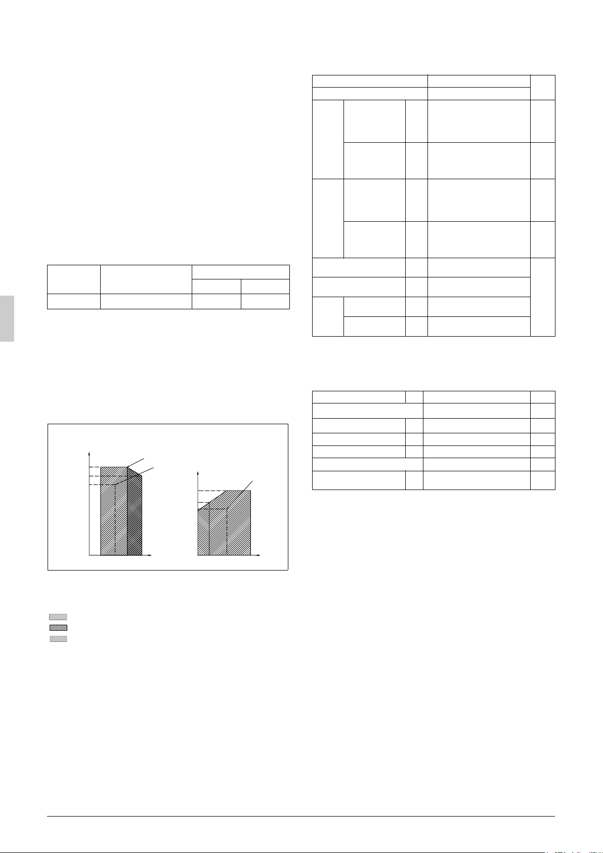
2-2 Standard operation limit
Normal operation
The figures below assume following operating conditions for indoor
and outdoor units:
Equivalent pipe length
From outdoor unit to BP unit..................................... 16.4 ft (5 m)
From BP unit to indoor unit.......................................... 9.8ft (3 m)
Level difference ............................................................. 0 ft (0 m)
Cooling Heating
A
115 (46)
104 (40)
95 (35)
*(c)
*(a)
60 (15.5)
Quantity of indoor units
C
50 (10)
43 (6)
41 (5)
Max. Min.
(H/P model only)
unit : ˚F(˚C)
*(b)
2-3 Spec list
For operating conditions marked with a *(a)(b) in the table, see “2-2
Standard operation limit”.
Model name RMXS48LVJU
Refrigerant type
Cooling
performance
Heating
Wall
mounted
Duct
External dimensions
(height × width × depth)
Mass
Connection piping
performance
Energy use during
cooling
Energy use during
heating
Cooling
performance
Heating
performance
Energy use during
cooling
Energy use during
heating
Gas line piping
Liquid line piping
(MBh)
(kW)
(MBh)
(kW)
(kW) 4.64
(kW)
(MBh)
(kW)
(MBh)
(kW)
(kW) 5.13
(kW)
(inch)
(mm)
(lb.)
(kg)
(inch)
(mm)
(inch)
(mm)
R410A
48
14.1
54
15.8
3.98
48
14.1
54
15.8
5.27
52-15/16 × 35-7/16 × 12-5/8
1345 × 900 × 320
283
129
φ
3/4
φ
19.1
φ
3/8
φ
9.4
Remarks
* (a)
* (b)
* (a)
* (b)
* (a)
* (b)
* (a)
* (b)
2-4 Electrical properties
For operating conditions marked with a *(c) in the table, see “2-2
Standard operation limit”.
Model name
Phase
Frequency
Voltage
Voltage tolerance range
Rated current for fuses
Maximum outdoor unit operat-
ing current
H/P
(Hz)
(V)
(%) ±10
(A)
RMXS48LVJU
Single
60Hz
208/230V
30
27
Remarks
* (c)
23 (–5)
50
(10)
57
(19)82(28)
(14)
73
66
(23)
5 (–15)
B
50
(10)57(14)70(21)82(28)
D
A Outdoor temperature (°FDB / °CDB)
B Indoor temperature (°FWB / °CWB)
C Outdoor temperature (°FWB / °CWB)
D Indoor temperature (°FDB / °CDB)
Range for continuous operation
Range for pull down operation
Range for warming up operation
3 English
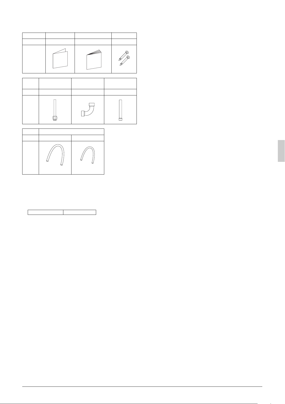
2-5 Standard supplied accessories
Make sure that the accessories shown below are all present.
(The accessories can be found behind the front panel.)
Name Regarding use Installation manual Binding band
Quantity 1 1 6 pcs.
Shape
Name
Quantity 1 pc. 1 pc. 1 pc.
Shape
Name Insulation tube
Quantity 1 pc. 1 pc.
Shape
Gas side
accessory pipe (1)
(large)
(Refer to figure 30)
1. Accessories
2. Screw for front panel
3. Front panel
Gas side
accessory pipe (2)
(small)
Gas side
accessory pipe (3)
2-6 Option accessory
• Refrigerant branching kit
REFNET joint KHRP26M22T
* See “7. PRECAUTIONS ON REFRIGERANT PIPING” for
details on how to connect refrigerant branch kits and how many
are needed.
3. BEFORE INSTALLATION
<Transporting the Unit>
As shown in figure 2, bring the unit slowly. (Take care not to let hands
or things come in contact with rear fins.)
(Refer to figure 2)
1. Air outlet grille
2. Intake hole
3. Corner
4. Outdoor unit
5. Handle
6. Front
7. Rear
8. Always hold the unit by the corners, as holding it by the
side intake holes on the casing may cause them to
Use only accessories and parts which are of the designated specification when installing.
deform.
4. SELECTING INSTALLATION SITE
(1) Select an installation site where the following conditions are
satisfied and that meets with your customer’s approval.
• Places which are well-ventilated.
• Places where the unit does not bother next-door neighbors.
• A locations where small animals will not make nests in the unit.
• Safe places which can withstand the unit’s weight and vibration
and where the unit can be installed level.
• Locations not exposed to rain.
• A locations where there is enough space to install the unit.
• Places where the indoor and outdoor unit’s piping and wiring
lengths come within the allowable ranges.
• A location where there is no risk of flammable gas leaking.
(2) If the unit is installed in a location where it might be
exposed to strong wind, install as per figure 3.
• 16.4 ft/sec (5 m/sec) or more strong wind blown against the out-
door unit’s air outlet causes the outdoor unit to deteriorate in air
capacity and suck in the air blown out of its air outlet (short circuit), and the following effects may result.
• Drop in performance.
• Increased frost formation in heating mode.
• Shutting down due to increase in pressure.
• If very strong wind blows continuously on the side of the outdoor
unit with the outlet vent, the fan may turn in reverse at high
speed and break, so install as per figure 3.
(Refer to figure 3)
1. Turn the air outlet side toward the building’s wall, fence or
windbreak screen.
2. Air inlet grille
3. Ensuring there is enough space for installing the unit.
4. Set the outlet side at a right angle to the direction of the
wind.
5. Strong wind
6. Blown air
(3) In installing the unit in a place frequently exposed to snow,
pay special attention to the following:
• Elevate the foundation as high as possible.
• Attach the snow hood (field supply).
• Remove the rear inlet grille to prevent snow from accumulating
on the rear fins.
(4) The outdoor unit may short circuit depending on its environment,
so use the louvers (field supply).
(5) The refrigerant gas (R410A) is a safe, non-toxic and non-flam-
mable gas, but if it leaks into the room, the concentration may
exceed tolerance levels, especially in small rooms, so steps need
to be taken to prevent refrigerant leakage. See the equipment
design reference for details.
(6) Inverter-type air conditioners sometimes cause static in other
electrical appliances.
When selecting an installation location, make sure the air conditioner and all wiring are sufficiently far away from radios, computers, stereos, and other appliances, as shown in figure 1.
Particularly for locations with weak reception, ensure there is a
distance of at least 9.8 ft (3 m) for indoor remote controllers,
place power supply wiring and inter-unit wiring in conduits, and
ground the conduits. Use shielded wire for inter-unit wiring.
(Refer to figure 1)
1. Indoor unit
2. Branch switch (ground-fault circuit interrupter)
3. Remote controller
4. Personal computer or radio
5. BP unit
(7) Space needed for installation
<Precautions when installing units in series>
• The direction for inter-unit piping is either forward or down when
installing units in series.
• If the piping is brought out from the back, the outdoor unit will
require at least 10 inch (250 mm) from its right side.
(7)-1 IN CASE OBSTACLES EXIST ONLY IN FRONT OF THE
AIR INLET
When nothing is obstructing the top
1.
Installation of single unit
• In case obstacles exist only in front of the air inlet
(Refer to figure 4-[1])
• In case obstacles exist in front of the air inlet and on both sides
of the unit (Refer to figure 4-[2])
English 4
2.
In case of installing multiple units (2 units or more) in lateral connection per row
• In case obstacles exist in front of the air inlet and on both sides
of the unit (Refer to figure 4-[3])
When something is obstructing the top
1.
Installation of single unit
• In case obstacles exist only in front of the air inlet
(Refer to figure 5-[1])
• In case obstacles exist in front of the air inlet and on both sides
of the unit (Refer to figure 5-[2])
2.
In case of installing multiple units (2 units or more) in lateral connection per row
• In case obstacles exist in front of the air inlet and on both sides
of the unit (Refer to figure 5-[3])
(7)-2 IN CASE OBSTACLES EXIST IN FRONT OF THE OUTLET
SIDE
When nothing is obstructing the top
1.
Installation of single unit (Refer to figure 6-[1])
2.
In case of installing multiple units (2 units or more) in lateral connection per row (Refer to figure 6-[2])
When something is obstructing the top
1.
Installation of single unit (Refer to figure 6-[3])
2.
In case of installing multiple units (2 units or more) in lateral connection per row (Refer to figure 6-[4])
(7)-3 IN CASE OBSTACLES EXIST IN FRONT OF BOTH THE
AIR INLET AND OUTLET SIDES
Pattern 1: Where obstacle in front of the air outlet is higher than the
When nothing is obstructing the top
1.
2.
When something is obstructing the top
1.
2.
Pattern 2: Where obstacles in front of the air outlet is lower than the
When nothing is obstructing the top
1.
2.
unit.
(There is no height limit for obstructions on the intake side.)
Installation of single unit (Refer to figure 7-[1])
In case of installing multiple units (2 units or more) in lateral connection per row (Refer to figure 7-[2])
Installation of single unit (Refer to figure 7-[3])
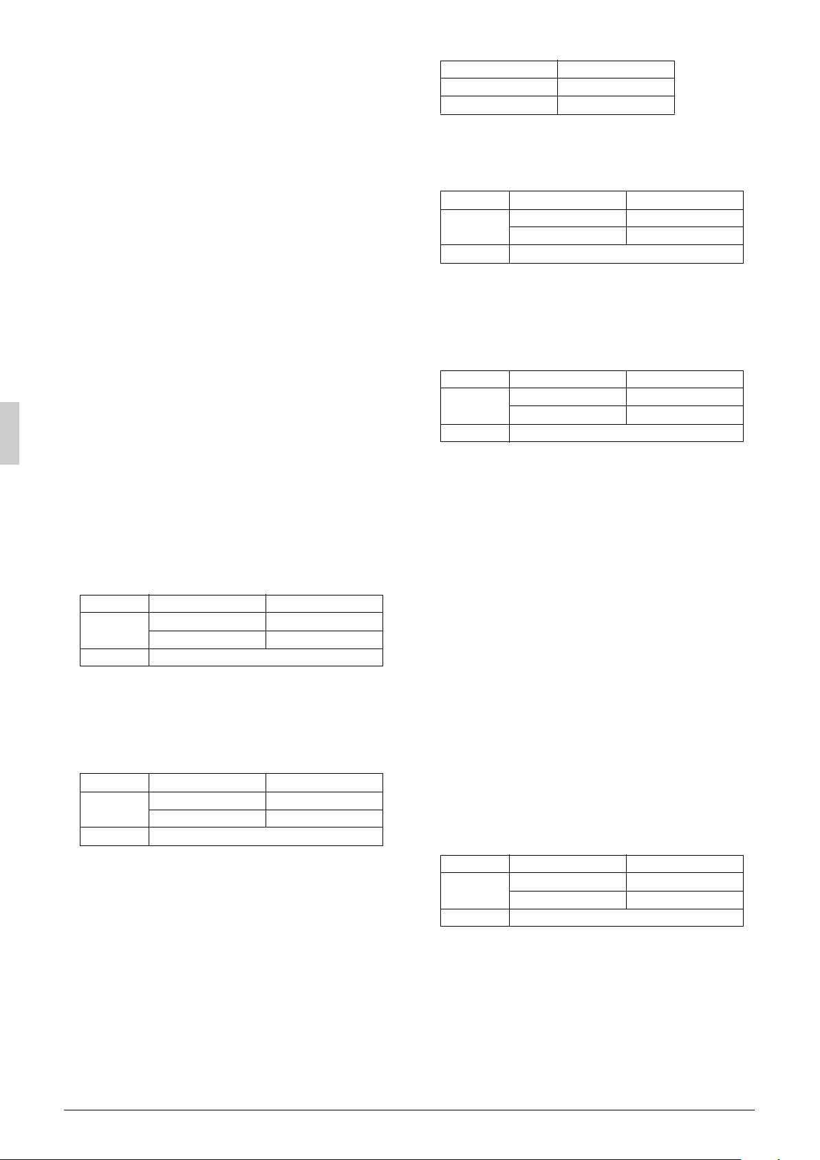
Relation of dimensions of H, A, and L are shown in the table below.
inch (mm)
LA
≤
1/2H 30 (750)0
≤
H
L
H < L
Note
Get the lower part of the frame sealed so that air from the outlet
does not bypass.
Series installation (up to 2 units) (Refer to figure 7-[4])
Relation of dimensions of H, A, and L are shown in the table
below.
≤
H
L
H < L
Note
1. Get the lower part of the frame sealed so that air from the outlet does not bypass.
2. Only two units at most can be installed in series.
unit.
(There is no height limit for obstructions on the intake
side.)
Installation of single unit (Refer to figure 7-[5])
In case of installing multiple units (2 units or more) in lateral connection per row (Refer to figure 7-[6])
Relation of dimensions of H, A, and L are shown in the table
below.
0 < L
≤
1/2H < L
0 < L
1/2H < L
H 40 (1000)
Set the frame to be L ≤ H
inch (mm)
LA
≤
1/2H 40 (1000)
≤
H 50 (1250)
Set the frame to be L ≤ H
inch (mm)
LA
≤
1/2H 10 (250)
0 < L
≤
1/2H < L
When something is obstructing the top
1.
Installation of single unit (Refer to figure 7-[7])
Relation of dimensions of H, A, and L are shown in the table
below.
≤
H
L
H < L
Note
Get the lower part of the frame sealed so that air from the outlet
does not bypass.
2.
Series installation (up to 2 units) (Refer to figure 7-[8])
Relation of dimensions of H, A, and L are shown in the table
below.
≤
H
L
H < L
Note
1. Get the lower part of the frame sealed so that air from the outlet does not bypass.
2. Only 2 units at most can be installed in series.
(7)-4 IN CASE OF STACKED INSTALLATION
1.
In case obstacles exist in front of the outlet side
(Refer to figure 8-[1])
Note
1. No more than 2 units should be stacked.
2. About 4 inch (100 mm) is required as the dimension for laying
the upper outdoor unit’s drain pipe.
3. Shut off the Z part (the area between the upper outdoor unit
and the lower outdoor unit) so that outlet air does not bypass.
2.
In case obstacles exist in front of the air inlet
Note
1. No more than 2 units should be stacked.
2. About 4 inch (100 mm) is required as the dimension for laying
the upper outdoor unit’s drain pipe.
3. Shut off the Z part (the area between the upper outdoor unit
and the lower outdoor unit) so that outlet air does not bypass.
(7)-5 IN CASE OF MULTIPLE-ROW INSTALLATION (FOR ROOF
TOP USE, ETC.)
1.
In case of installing 1 unit per row (Refer to figure 9-[1])
2.
In case of installing multiple units (2 units or more) in lateral connection per row (Refer to figure 9-[2])
Relation of dimensions of H, A, and L are shown in the table
below.
≤
H
L
H < L
H12 (300)
inch (mm)
LA
≤
1/2H 4 (100)
0 < L
≤
1/2H < L
0 < L
1/2H < L
0 < L
1/2H < L
H 8 (200)
Set the frame to be L ≤ H
inch (mm)
LA
≤
1/2H 10 (250)
≤
H12 (300)
Set the frame to be L ≤ H
(Refer to figure 8-[2])
inch (mm)
LA
≤
1/2H 10 (250)
≤
H12 (300)
Installation impossible.
5 English
 Loading...