

Page 1
I
NSTALLATION
I
NSTRUCTIONS FOR
*MSS9* & *CSS9*
INGLE-STAGE
S
(Type FSP CATEGORY IV Direct
or Non Direct Vent Air Furnace)
These furnaces comply with requirements embodied in the American National Standard / National Standard of Canada ANSI Z21.47·CSA-2.3
Gas Fired Central Furnaces.
GAS F
URNACE
O
NLY PERSONNEL THAT HAVE BEEN TRAINED TO INSTALL, ADJUST, SERVICE OR
REPAIR (HEREINAFTER
SHOULD SERVICE THE EQUIPMENT
FOR ANY INJURY OR PROPERTY DAMAGE ARISING FROM IMPROPER SERVICE OR
SERVICE PROCEDURES
FOR ANY INJURY OR PROPERTY DAMAGE WHICH MAY RESULT
JURISDICTIONS THAT REQUIRE ONE OR MORE LICENSES TO SERVICE THE EQUIPMENT
SPECIFIED IN THIS MANUAL, ONLY LICENSED PERSONNEL SHOULD SERVICE THE
EQUIPMENT
THE EQUIPMENT SPECIFIED IN THIS MANUAL, OR ATTEMPTING TO INSTALL, ADJUST
SERVICE OR REPAIR THE EQUIPMENT SPECIFIED IN THIS MANUAL WITHOUT PROPER
TRAINING MAY RESULT IN PRODUCT DAMAGE, PROPERTY DAMAGE, PERSONAL
INJURY OR DEATH
, “
SERVICE
”)
THE EQUIPMENT SPECIFIED IN THIS MANUAL
. THE
MANUFACTURER WILL NOT BE RESPONSIBLE
. IF
YOU SERVICE THIS UNIT, YOU ASSUME RESPONSIBILITY
. IN
ADDITION, IN
. I
MPROPER INSTALLATION, ADJUSTMENT, SERVICING OR REPAIR OF
.
TABLE OF CONTENTS
,
Installer:
Affix all manuals
adjacent to the unit.
As a professional installer you have an obligation to know
the product better than the customer. This includes all safety
precautions and related items.
Prior to actual installation, thoroughly familiarize yourself
with this Instruction Manual. Pay special attention to all
safety warnings. Often during installation or repair it is
possible to place yourself in a position which is more
hazardous than when the unit is in operation.
Remember, it is your responsibility to install the product
safely and to know it well enough to be able to instruct a
customer in its safe use.
Safety is a matter of common sense...a matter of thinking
before acting. Most dealers have a list of specific good
safety practices...follow them.
The precautions listed in this Installation Manual are intended
as supplemental to existing practices. However, if there is
a direct conflict between existing practices and the content
of this manual, the precautions listed here take precedence.
RECOGNIZE THIS SYMBOL
AS A SAFETY PRECAUTION.
*NOTE: Please contact your distributor or our website for
the applicable Specification Sheet referred to in this manual.
SAFETY CONSIDERATIONS .......................................... 3
SHIPPING INSPECTION ............................................ 4
ELECTROSTATIC DISCHARGE (ESD) PRECAUTIONS .................... 4
TO THE INSTALLER ............................................. 5
PRODUCT A PPLICATION ............................................. 5
LOCATION REQUIREMENTS & CONSIDERATIONS ......................... 6
CLEARANCES AND A CCESSIBILITY ................................... 7
EXISTING FURNACE REMOVAL ..................................... 8
THERMOSTAT LOCATION .......................................... 8
COMBUSTION & VENTILATION A IR REQUIREMENTS ..................... 8
INSTALLATION POSITIONS ............................................ 9
HORIZONTAL A PPLICATIONS & CONSIDERATIONS ........................ 9
FURNACE SUSPENSION ........................................... 9
FRONT COVER PRESSURE SWITCH TUBE L OCATION ................. 9
DRAIN TRAP AND LINES ......................................... 9
LEVELING ...................................................... 9
ALTERNATE ELECTRICAL AND GAS L INE C ONNECTIONS .............. 10
DRAIN PAN ................................................... 10
FREEZE PROTECTION ........................................... 10
PROPANE GAS/HIGH A LTITUDE INSTALLATIONS ....................... 10
VENT/FLUE PIPE & COMBUSTION A IR PIPE ......................... 10
DUAL CERTIFICATION: NON-DIRECT/DIRECT VENT ................. 11
MATERIALS AND JOINING METHODS .............................. 11
PROPER VENT/FLUE AND COMBUSTION A IR PIPING PRACTICES ...... 11
TERMINATION LOCATIONS ........................................12
CANADIAN VENT PIPE & COMBUSTION A IR PIPE R EQUIREMENTS ..... 13
STANDARD FURNACE CONNECTIONS .............................. 13
VENT/INTAKE T ERMINATIONS FOR INSTALLATION OF MULTIPLE DIRECT
VENT FURNACES ............................................... 18
CONCENTRIC VENT TERMINATION................................. 18
SIDE WALL VENT KIT .......................................... 18
CONDENSATE DRAIN LINES & DRAIN TRAP .......................... 18
GENERAL DRAIN I NFORMATION ................................... 19
FIELD SUPPLIED DRAIN ......................................... 19
UPFLOW MODEL INSTALLED VERTICALLY .......................... 19
IOG-2009K
11/2017
5151 San Felipe Suite 500
Houston, TX 77056
www.goodmanmfg.com • www.amana-hac.com
© 2014-2017 Goodman Manufacturing Company, L.P.
is a registered trademark of Maytag Corporation or its related companies
and is used under license. All rights reserved.
Page 2

DRAIN EXITING RIGHT S IDE ..................................... 19
DRAIN EXITING LEFT SIDE ...................................... 20
UPFLOW MODEL INSTALLED HORIZONTALLY WITH RIGHT SIDE DOWN 20
UPFLOW MODEL INSTALLED HORIZONTALLY WITH LEFT SIDE DOWN .21
UPFLOW MODEL INSTALLED HORIZONTALLY WITH LEFT SIDE DOWN -
ALTERNATE .................................................... 21
COUNTERFLOW MODEL INSTALLED V ERTICALLY ....................22
DRAIN EXITING L EFT SIDE (SEE F IGURE 26) ..................... 22
DRAIN EXITING RIGHT SIDE (SEE FIGURE 27) .................... 22
COUNTERFLOW MODEL INSTALLED HORIZONTALLY WITH RIGHT SIDE
DOWN (SEE FIGURE 28) ...................................... 23
COUNTERFLOW MODEL INSTALLED HORIZONTALLY
LEFT SIDE DOWN ..................................... 23
WITH
ELECTRICAL CONNECTIONS ......................................... 24
WIRING HARNESS .............................................. 24
115 VOLT LINE CONNECTIONS .................................. 24
JUNCTION BOX RELOCATION ..................................... 25
24 VOLT T HERMOSTAT WIRING .................................. 25
SINGLE-STA GE HEATING THERMOSTAT A PPLICATION ................ 25
FOSSIL FUEL A PPLICATIONS ...................................... 25
TWINNING ....................................................26
GAS SUPPLY AND PIPING .......................................... 26
HIGH A LTITUDE D ERATE ........................................ 27
PROPANE GAS CONVERSION ..................................... 27
GAS PIPING C ONNECTIONS ......................................27
PROPANE GAS TANKS AND PIPING ............................... 29
CIRCULATING A IR & FILTERS ....................................... 30
DUCT WORK - AIR FLOW ....................................... 30
CHECKING DUCT S TATIC ........................................ 30
BOTTOM RETURN AIR OPENING [UPFLOW MODELS] ............... 31
FILTERS - READ THIS S ECTION B EFORE I NSTALLING
THE RETURN A IR DUCT WORK ............................... 31
HORIZONTAL INSTALLATIONS ..................................... 32
STARTUP PROCEDURE & ADJUSTMENT .............................. 32
DRAIN TRAP P RIMING .......................................... 32
FURNACE OPERATION ........................................... 32
GAS SUPPLY PRESSURE M EASUREMENT ........................... 33
GAS MANIFOLD PRESSURE MEASUREMENT AND ADJUSTMENT ........ 34
GAS INPUT RAT E MEASUREMENT (NATURAL GAS O NLY) ...........34
TEMPERATURE RISE ............................................34
CIRCULATOR BLOWER SPEEDS ...................................35
BLOWER HEAT OFF DELAY TIMINGS ............................. 35
NORMAL SEQUENCE OF OPERATION .................................35
POWER UP ................................................... 35
HEATING M ODE ............................................... 35
COOLING MODE ............................................... 35
FAN ONLY MODE ............................................. 36
OPERATIONAL C HECKS ............................................ 36
SAFETY CIRCUIT DESCRIPTION ...................................... 36
INTEGRATED CONTROL MODULE ................................. 36
PRIMARY LIMIT ................................................. 36
AUXILIARY LIMIT ............................................... 36
ROLLOUT LIMIT ............................................... 36
PRESSURE SWITCHES ........................................... 36
FLAME SENSOR ................................................ 36
TROUBLESHOOTING ............................................... 36
ELECTROSTATIC DISCHARGE (ESD) PRECAUTIONS ................... 36
DIAGNOSTIC CHART ............................................ 37
RESETTING FROM LOCKOUT ..................................... 37
MAINTENANCE ................................................... 37
ANNUAL INSPECTION ........................................... 37
FILTERS ....................................................... 37
BURNERS ..................................................... 38
INDUCED DRAFT AND CIRCULATOR BLOWERS ......................38
CONDENSATE TRAP AND DRAIN SYSTEM (QUALIFIED SERVICER ONLY)38
FLAME SENSOR (QUALIFIED SERVICER ONLY) .....................38
FLUE PASSAGES (QUALIFIED SERVICER ONLY)..................... 38
BEFORE LEAVING AN I NSTALLATION ................................. 38
REPAIR AND R EPLACEMENT PARTS .................................. 38
TROUBLESHOOTING CHART ........................................ 39
TROUBLESHOOTING CHART ........................................ 40
AIRFLOW .................................................... 41-42
*MSS92*** & *CSS92***A* .................................. 41
*MSS96*** & *CSS96***A* .................................. 42
WIRING DIAGRAM ................................................ 43
*MSS92*** & *CSS92***A* ............................... 43
WIRING DIAGRAM ................................................ 44
*MSS96*** & *CSS96***A*
(WITH PCBBF138 CONTROL) .......................... 44
WIRING DIAGRAM ................................................ 45
*MSS96*** & *CSS96***A*
(WITH PCBBF140 CONTROL) .......................... 45
SPECIAL INSTRUCTIONS FOR PRODUCTS I NSTALLED
THE STAT E OF M ASSACHUSETTS ............................... 47
IN
2
Page 3
S
AFETY
C
ONSIDERATIONS
Adhere to the following warnings and cautions when installing, adjusting, altering, servicing, or operating the furnace.
To ensure proper installation and operation, thoroughly read
this manual for specifics pertaining to the installation and
application of this product.
This furnace is manufactured for use with natural gas. It
may be field converted to operate on L.P. gas by using the
appropriate L.P. conversion kit listed in the PROPANE GAS/
HIGH ALTITUDE INSTALLATIONS section of this manual
Install this furnace only in a location and position as specified in LOCATION REQUIREMENTS & CONSIDERATIONS sec-
tion and INSTALLATION POSITIONS section of this manual.
Provide adequate combustion and ventilation air to the furnace as specified in COMBUSTION & VENTILATION AIR RE-
QUIREMENTS section of this manual.
Combustion products must be discharged to the outdoors.
Connect this furnace to an approved vent system only, as
specified in VENT/FLUE PIPE & COMBUSTION AIR PIPE section of this manual.
Never test for gas leaks with an open flame. Use a commercially available soap solution made specifically for the detection of leaks to check all connections, as specified in GAS
SUPPLY AND PIPING section of this manual.
Always install a furnace to operate within the furnace’s intended temperature-rise range with a duct system which has
external static pressure within the allowable range, as specified on the furnace rating plate and OPERATIONAL CHECKS
section of these instructions.
When a furnace is installed so that supply ducts carry air
circulated by the furnace to areas outside the space containing the furnace, the return air shall also be handled by duct(s)
sealed to the furnace casing and terminating outside the
space containing the furnace.
A gas-fired furnace for installation in a residential garage
must be installed as specified in the LOCATION REQUIRE-
MENTS AND CONSIDERATIONS section of this manual.
This furnace may be used as a construction site heater only
if certain conditions are met. These conditions are listed in
the PRODUCT APPLICATION section of this manual.
WARNING
TO
PREVENT PERSONAL INJURY OR DEATH DUE TO IMPROPER
INSTALLATION, ADJUSTMENT, ALTERATION, SERVICE OR MAINTENANCE
REFER TO THIS MANUAL
INFORMATION, CONSU LT A QUALIFIED INSTALLER, SERVICER AGENCY OR
THE GAS SUPPLIER
. FOR
ADDITIONAL ASSISTANCE OR
.
WARNING
IF
THE INFORMATION IN THESE INSTRUCTIONS IS NOT FOLLOWED
EXACTLY, A FIRE OR EXPLOSION MAY RESULT CAUSING PROPERTY
DAMAGE
,
PERSONAL INJURY OR LOSS OF LIFE
DO
NOT STORE OR USE GASOLINE OR OTHER FLAMMABLE VAPORS AND
LIQUIDS IN THE VICINITY OF THIS OR ANY OTHER APPLIANCE
.
.
WHAT TO DO IF YOU SMELL GAS:
D
O NOT TRY TO LIGHT ANY APPLIANCE
D
O NOT TOUCH ANY ELECTRICAL SWITCH; DO NOT USE ANY PHONE
IN YOUR BUILDING
I
MMEDIATELY CALL YOUR GAS SUPPLIER FROM A NEIGHBOR’S
PHONE
. F
I
F YOU CANNOT REACH YOUR GAS SUPPLIER, CALL THE FIRE
DEPARTMENT
I
NSTALLATION AND SERVICE MUST BE PERFORMED BY A QUALIFIED
INSTALLER, SERVICE AGENCY OR THE GAS SUPPLIER
.
OLLOW THE GAS SUPPLIER’S INSTRUCTIONS
.
.
.
.
WARNING
T
HIS PRODUCT CONTAINS OR PRODUCES A CHEMICAL OR CHEMICALS
WHICH MAY CAUSE SERIOUS ILLNESS OR DEATH AND WHICH ARE
KNOWN TO THE STATE OF CALIFORNIA TO CAUSE CANCER, BIRTH
DEFECTS OR OTHER REPRODUCTIVE HARM
.
WARNING
H
EATING UNIT SHOULD NOT BE UTILIZED WITHOUT REASONABLE
ROUTINE, INSPECTION, MAINTENANCE AND SUPERVISION
BUILDING IN WHICH ANY SUCH DEVICE IS LOCATED WILL BE VACANT
CARE SHOULD BE TAKEN THAT SUCH DEVICE IS ROUTINELY INSPECTED
MAINTAINED AND MONITORED. IN THE EVENT THAT THE BUILDING
MAYBE EXPOSED TO FREEZING TEMPERATURES AND WILL BE VACANT
ALL WATER-BEARING PIPES SHOULD BE DRAINED, THE BUILDING SHOULD
BE PROPERLY WINTERIZED, AND THE WATER SOURCE CLOSED. IN THE
EVENT THAT THE BUILDING MAY BE EXPOSED TO FREEZING
TEMPERATURES AND WILL BE VACANT, ANY HYDRONIC COIL UNITS
SHOULD BE DRAINED AS WELL AND, IN SUCH CASE, ALTERNATIVE HEAT
SOURCES SHOULD BE UTILIZED
.
. IF
THE
,
,
,
,
,
CAUTION
FROZEN AND BURST WATER PIPE HAZARD
F
AILURE TO PROTECT AGAINST THE RISK OF FREEZING MAY RESULT IN
PROPERTY DAMAGE
S
PECIAL PRECAUTIONS
AREA WHICH MAY DROP BELOW FREEZING
OPERATION OR DAMAGE TO EQUIPMENT
ENVIRONMENT HAS THE POTENTIAL OF FREEZING, THE DRAIN TRAP AND
DRAIN LINE MUST BE PROTECTED
HEATERS, ELECTRIC HEAT TAPE AND/OR
RECOMMENDED FOR THESE INSTALLATIONS
.
MUST BE
MADE IF INSTALLING FURNACE IN AN
. T
HIS CAN CAUS E IMPROPER
. IF
THE FURNACE
. THE
USE OF ACCESSORY DRAIN TRAP
RV
ANTIFREEZE IS
.
WARNING
TO
PREVENT POSSIBLE PROPERTY DAMAGE, PERSONAL INJURY OR
DEATH DUE TO ELECTRICAL SHOCK, THE FURNACE MUST BE LOCATED TO
PROTECT THE ELECTRICAL COMPONENTS FROM WATER
.
Drain trap must be primed at time of installation. Trap is
internally partitioned; add water to both inlet ports until water appears at both sides of the outlet opening. Failure to
prime trap at time of installation may have a negative effect on combustion quality and pressure switch action.
3
Page 4
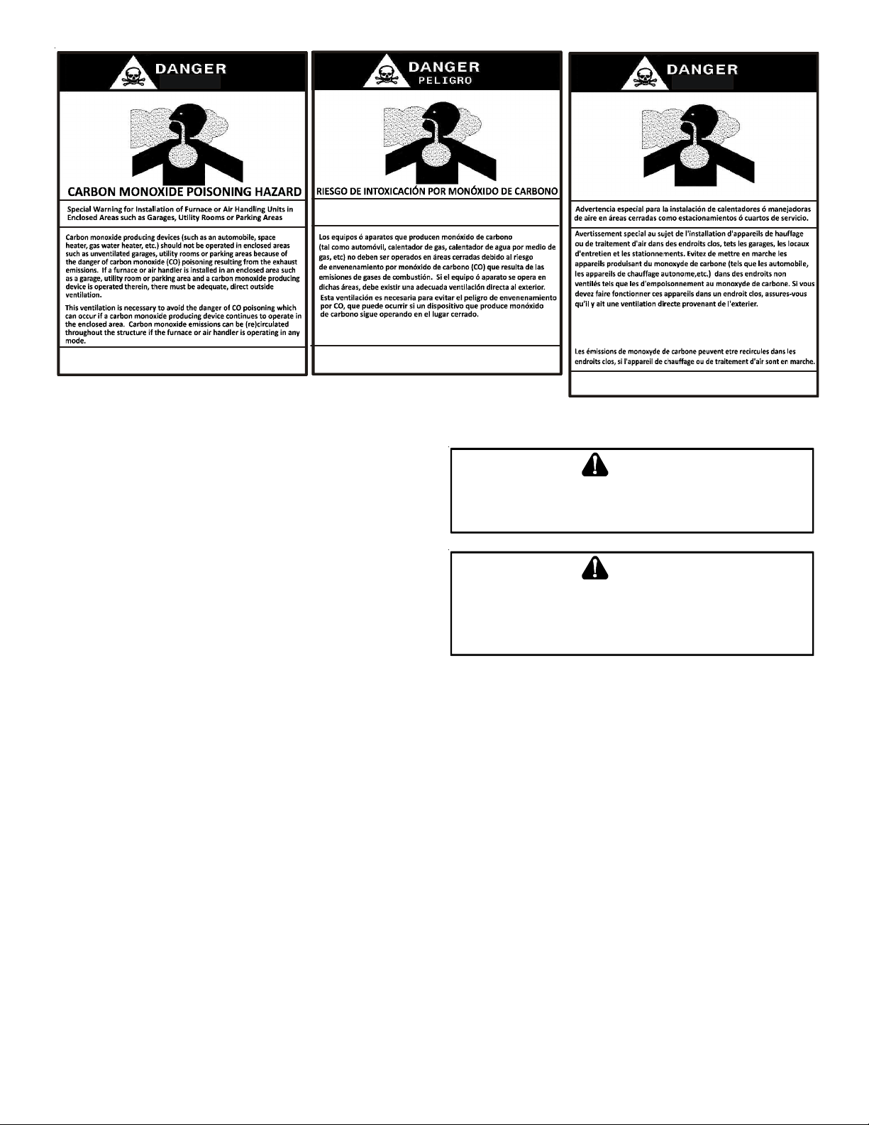
Advertencia especial para la instalación de calentadores ó manejadoras
de aire en ár eas cerradas com o estacionamientos ó cuartos de servi cio.
RISQUE D'EMPOISONNEMENT AU
MONOXYDE DE CARBONE
Las emis iones de monóxido d e carbono pueden circular a trav és
del aparato cuan do se opera en cualquier mod o.
CO can cause serious illness inc luding permane nt b rain
damage or death.
B10259-216
El monóxido de carbono pu ede causar enfe rmedade s severa s
como daño cerebral permane nte ó muerte.
SHIPPING I NSPECTION
All units are securely packed in shipping containers tested according to International Safe Transit Association specifications.
The carton must be checked upon arrival for external damage. If
damage is found, a request for inspection by carrier’s agent
must be made in writing immediately.
The furnace must be carefully inspected on arrival for damage
and bolts or screws which may have come loose in transit. In the
event of damage the consignee should:
1. Make a notation on delivery receipt of any visible damage
to shipment or container.
2. Notify carrier promptly and request an inspection.
3. With concealed damage, carrier must be notified as soon
as possible - preferably within five days.
4. File the claim with the following support documents within
a nine month statute of limitations.
• Original or certified copy of the Bill of Lading, or
indemnity bond.
• Original paid freight bill or indemnity in lieu thereof.
• Original or certified copy of the invoice, showing trade
and other discounts or reductions.
• Copy of the inspection report issued by carrier’s
representative at the time damage is reported to carrier.
The carrier is responsible for making prompt inspection of damage and for a thorough investigation of each claim. The distributor or manufacturer will not accept claims from dealers for transportation damage.
ELECTROSTATIC DISCHARGE (ESD) PRECAUTIONS
NOTE: Discharge your body’s static electricity before touching
unit. An electrostatic discharge can adversely affect electrical
components.
Use the following precautions during furnace installation and servicing to protect the integrated control module from damage. By
putting the furnace, the control, and the person at the same
Cette ventilation est nécessaire pour éviter le danger d'intoxication
au CO pouvant survenir si un ap pareil produis ant du monoxy de
de carb one continue de fonctionner au sein de la zone confin ée.
B10259-216
Le monoxy de de
des
dommag es permanen ts au cerv eau et meme la mort.
carbone peut causer des maladies graves telles que
WARNING
S
HOULD OVERHEATING OCCUR OR THE GAS SUPPLY FAIL TO SHUT OFF
TURN OFF THE MANUAL GAS SHUTOFF VALVE EXTERNAL TO THE
FURNACE BEFORE TURNING OFF THE ELECTRICAL SUPPLY
.
WARNING
P
OSSIBLE PROPERTY DAMAGE, PERSONAL INJURY OR DEATH DUE TO
FIRE, EXPLOSION, SMOKE, SOOT, CONDENSATIO N, ELECTRICAL SHOCK
OR CARBO N MONOXIDE MAY RESULT FROM IMPROPER INSTALLATION
REPAIR OPERATION, OR MAINTENANCE OF THIS PRODUCT
.
electrostatic potential, these steps will help avoid exposing
the integrated control module to electrostatic discharge. This
procedure is applicable to both installed and non-installed
(ungrounded) furnaces.
1. Disconnect all power to the furnace. Do not touch the
integrated control module or any wire connected to the
control prior to discharging your body’s electrostatic
charge to ground.
2. Firmly touch a clean, unpainted, metal surface of the
furnaces near the control. Any tools held in a person’s
hand during grounding will be discharged.
3. Service integrated control module or connecting wiring
following the discharge process in step 2. Use caution not
to recharge your body with static electricity; (i.e., do not
move or shuffle your feet, do not touch ungrounded
objects, etc.). If you come in contact with an ungrounded
object, repeat step 2 before touching control or wires.
4. Discharge your body to ground before removing a new
control from its container. Follow steps 1 through 3 if
installing the control on a furnace. Return any old or new
controls to their containers before touching any ungrounded
object.
4
B10259-216
,
,
Page 5

TO THE INSTALLER
Before installing this unit, please read this manual thoroughly to
familiarize yourself with specific items which must be adhered
to, including but not limited to: unit maximum external static
pressure, gas pressures, BTU input rating, proper electrical connections, circulating air temperature rise, minimum or maximum CFM, and motor speed connections.
P
RODUCT APPLICATION
This furnace is primarily designed for residential home-heating
applications. It is NOT designed or certified for use in mobile
homes, trailers or recreational vehicles. Neither is it designed
or certified for outdoor applications. The furnace must be installed indoors (i.e., attic space, crawl space, or garage area
provided the garage area is enclosed with an operating door).
This furnace can be used in the following non-industrial commercial applications:
Schools, Office buildings, Churches, Retail stores, Nursing
homes, Hotels/motels, Common or office areas
In such applications, the furnace must be installed with the following stipulations:
• It must be installed per the installation instructions
provided and per local and national codes.
• It must be installed indoors in a building constructed on
site.
• It must be part of a ducted system and not used in a
free air delivery application.
• It must not be used as a “make-up” air unit.
• It must be installed as a two-pipe systems for
combustion air.
• All other warranty exclusions and restrictions apply This
furnace is an ETL dual-certified appliance and is
appropriate for use with natural or propane gas (NOTE:
If using propane, a propane conversion kit is required).
Dual certification means that the combustion air inlet pipe is
optional and the furnace can be vented as a:
Non-direct vent (single pipe) central forced air furnace
in which combustion air is taken from the installation
area or from air ducted from the outside or,
Direct vent (dual pipe) central forced air furnace in
which all combustion air supplied directly to the furnace
burners through a special air intake system outlined in
these instructions.
Gas furnaces manufactured on or after May 1, 2017 are not
permitted to be used in Canada for heating of buildings or
structures under construction.
In the U.S.A., this furnace may be used as a construction site
heater ONLY if all of the following conditions are met:
• The vent system is permanently installed per these
installation instructions.
• A room thermostat is used to control the furnace. Fixed
jumpers that provide continuous heating CANNOT be
used and can cause long term equipment damage. Bi-
metal thermostats, or any thermostat affected by
vibration, must not be used during construction.
• Return air ducts are provided and sealed to the furnace.
• A return air temperature range between 60ºF (16ºC)
and 80ºF (27ºC) is maintained.
• Air filters are installed in the system and replaced daily
during construction and upon completion of construction.
• The input rate and temperature rise are set per the
furnace rating plate.
• The furnace must be installed as a two pipe system,
using 100% outside air for combustion during
construction.
• The furnace heat exchanger, components, duct
system, air filters and evaporator coils are
thoroughly cleaned following final construction clean
up by a qualified person.
• All furnace operating conditions (including ignition, input
rate, temperature rise and venting) are verified
according to these installation instructions.
• Furnace doors must be in place on the furnace while
the furnace is operating in any mode.
• Damage or repairs due to failure to comply with
these requirements are not covered under the
warranty.
NOTE: The Commonwealth of Massachusetts requires that the
following additional requirements must also be met:
• Gas furnaces must be installed by a licensed plumber or
gas fitter.
• A T-handle gas cock must be used.
• If the unit is to be installed in an attic, the passageway
to and the service area around the unit must have
flooring.
To ensure proper furnace operation, install, operate and maintain the furnace in accordance with these installation and
operation instructions, all local building codes and ordinances.
In their absence, follow the latest edition of the National Fuel
Gas Code (NFPA 54/ANSI Z223.1), and/or CAN/CSA B149.1-15
Installation Codes, local plumbing or waste water codes, and other
applicable codes.
WARNING
TO
PREVENT PROPERTY DAMAGE, PERSONAL INJURY OR DEATH DUE TO
FIRE, DO NOT INSTALL THIS FURNACE IN A MOBILE HOME, TRAILER, OR
RECREATIONAL VEHICLE
.
5
Page 6
A copy of the National Fuel Gas Code (NFPA 54/ANSI Z223.1)
can be obtained from any of the following:
American National Standards Institute
23 West 43rd Street, 4th Floor
New York, NY 10036
National Fire Protection Association
1 Batterymarch Park
Quincy, MA 02169-7471
CSA International
8501 East Pleasant Valley
Independence, OH 441311
The rated heating capacity of the furnace should be greater than
or equal to the total heat loss of the area to be heated. The total
heat loss should be calculated by an approved method or in accordance with “ASHRAE Guide” or “Manual J-Load Calculations”
published by the Air Conditioning Contractors of America.
A copy of the CAN/CSA B149.1-15 Installation Codes can also
be obtained from:
CSA International
178 Rexdale Boulevard
Etobicoke, Ontario, Canada M9W 1R3
L
OCATION REQUIREMENTS
& C
ONSIDERATIONS
Follow the instructions listed below and the guidelines provided
in the Combustion and Ventilation Air Requirements section when
selecting a furnace location.
WARNING
TO
PREVENT POSSIBLE EQUIPMENT DAMAGE, PROPERTY DAMAGE
PERSONAL INJURY OR DEATH, THE FOLLOWING BULLET POINTS MUST BE
OBSERVED WHEN INSTALLING THIS UNIT
.
,
WARNING
P
OSSIBLE PROPERTY DAMAGE, PERSONAL INJURY OR DEATH DUE TO
FIRE, EXPLOSION, SMOKE, SOOT, CONDENSATIO N, ELECTRICAL SHOCK
OR CARBO N MONOXIDE MAY RESULT FROM IMPROPER INSTALLATION
REPAIR OPERATION, OR MAINTENANCE OF THIS PRODUCT
.
,
• Centrally locate the furnace with respect to the
proposed or existing air distribution system.
• Ensure the temperature of the return air entering the
furnace is between 55°F and 100°F when the furnace is
heating.
• Provide provisions for venting combustion products
outdoors through a proper venting system. Special
consideration should be given to vent/flue pipe routing
and combustion air intake pipe when applicable. Refer
to Vent/Flue Pipe and Combustion Air Pipe -Termination
Locations for appropriate termination locations and to
determine if the piping system from furnace to
termination can be accomplished within the guidelines
given. NOTE: The length of flue and/or combustion
air piping can be a limiting factor in the location of the
furnace.
• Locate the furnace so condensate flows downwards to
the drain. Do not locate the furnace or its condensate
drainage system in any area subject to below freezing
temperatures without proper freeze protection. Refer
to Condensate Drain Lines and Trap for further details.
• Ensure adequate combustion air is available for the
furnace. Improper or insufficient combustion air can
expose building occupants to gas combustion products
that could include carbon monoxide. Refer to
Combustion and Ventilation Air Requirements.
• Set the furnace on a level floor to enable proper
condensate drainage. If the floor becomes wet or damp
at times, place the furnace above the floor on a concrete
base sized approximately 1-1/2" larger than the base
of the furnace. Refer to the Horizontal Applications
and Considerations for leveling of horizontal furnaces.
• Ensure upflow or horizontal furnaces are not installed
directly on carpeting, or any other combustible material.
The only combustible material allowed is wood.
• A special accessory subbase must be used for upright
counterflow unit installations over any combustible
material (including wood). Refer to subbase instructions
for installation details. (NOTE: A subbase will not be
required if an air conditioning coil is located beneath
the furnace between the supply air opening and the
combustible floor.
• Exposure to contaminated combustion air will result in
safety and performance-related problems. Do not install
the furnace where the combustion air is exposed to the
following substances:
permanent wave solutions
chlorinated waxes or cleaners
chlorine-based
carbon tetrachloride
water softening chemicals
swimming pool chemicals
deicing salts or chemicals
halogen type refrigerants
printing inks
cleaning solutions (such as perchloroethylene)
paint removers
varnishes
hydrochloric acid
cements and glues
antistatic fabric softeners for clothes dryers
masonry acid washing materials
• Seal off a non-direct vent furnace if it is installed
near an area frequently contaminated by any of the
above substances. This protects the non-direct vent
furnace from airborne contaminants. To ensure that
the enclosed non-direct vent furnace has an adequate
supply of combustion air, vent from a nearby
uncontaminated room or from outdoors. Refer to
the Combustion and Ventilation Air Requirements
for details.
6
Page 7
• If the furnace is used in connection with a cooling coil
b
ible fl
unit, install the furnace upstream or in parallel with the
cooling coil unit. Premature heat exchanger failure will
result if the cooling unit is placed ahead of the furnace.
For vertical (upflow or downflow) applications, the
minimum cooling coil width shall not be less than
furnace width minus 1”. Additionally, a coil installed
above an upflow furnace or under a counterflow
furnace may be the same width as the furnace or
may be one size larger than the furnace. Example:
a “C” width coil may be installed with a “B” width
furnace.
For upflow applications, the front of the coil and
furnace must face the same direction.
• If the furnace is installed in a residential garage,
position the furnace so that the burners and ignition
source are located not less than 18 inches (457 mm)
above the floor. Protect the furnace from physical
damage by vehicles.
• If the furnace is installed horizontally, ensure the access
doors are not on the “up/top” or “down/bottom” side
of the furnace.
• Do not connect this furnace to a chimney flue that
serves a separate appliance designed to burn solid
fuel.
• On Counterflow Installations, the air conditioning
coil must be downstream on the supply (positive)
side of the furnace heat exchanger.
• Counterflow Installation over a noncombustible
floor. Before setting the furnace over the plenum
opening, ensure the surface around the opening is
smooth and level. A tight seal should be made
between the furnace base and floor by using a
silicone rubber caulking compound or cement grout.
• Counterflow Installation over a combustible floor. If
installation over a combustible floor becomes necessary,
use an accessory subbase (see Specification Sheet
applicable for your model for details.) A special accessory
subbase must be used for upright counterflow unit
installations over any combustible material including
wood. Refer to subbase instructions for installation
details. Follow the instructions with the subbase for
proper installation. Do not install the furnace directly
on carpeting, tile, or other combustible material other
than wood flooring. (NOTE: The subbase will not be
required if an air conditioning coil is installed between
the supply air opening on the furnace and the floor.)
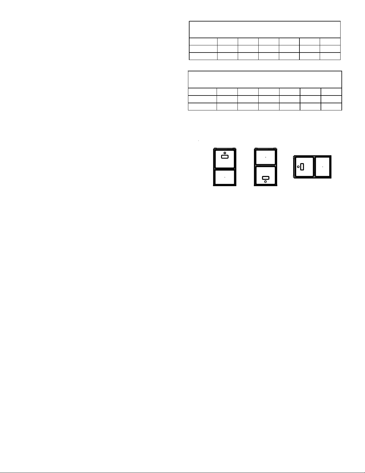
*M SS[92 & 96]* MINIM UM CLEARANCES TO COMBUSTIBLE M ATERIALS
(INCHES)
POSITION* SIDES REAR FRONT BOTTOM FLUE TOP
Upflow 0" 0" 3" C 0" 1"
Horizontal 6" 0" 3" C 0" 6"
C = I f placed on combustible floor, floor MUST be wood only.
*CSS[92 & 96]* MINIMUM CLEARANCES TO COMBUSTIBLE MATERIALS
(INCHES)
POSITION* SID ES REA R FRONT BOTTOM FLUE TOP
Counterflow0"0"3"NC0"1"
Horizont al 6" 0" 3" C 0" 6"
C = If placed on combustible floor , floor MUST be wood only .
NC = For installation on non-combustible floors only. A combustible subbase
must
e used for installations on combust
TOP
SIDE SIDE SIDE
BOTTOM
Upflow Counterflow Horizontal
Figure 1
ooring.
TOP
BOTTOM
CLEARANCES AND ACCESSIBILITY
NOTES:
• For servicing or cleaning, a 24” front clearance is
required.
• Unit connections (electrical, flue and drain) may
necessitate greater clearances than the minimum
clearances listed above.
• In all cases, accessibility clearance must take
precedence over clearances from the enclosure
where accessibility clearances are greater.
Installations must adhere to the clearances to combustible
materials to which this furnace has been design certified.
The minimum clearance information for this furnace is provided on the unit’s clearance label. These clearances must
be permanently maintained. Clearances must also accommodate an installation’s gas, electrical, and drain trap and
drain line connections. If the alternate combustion air intake or vent/flue connections are used additional clearance
must be provided to accommodate these connections. Refer
to Vent/Flue Pipe and Combustion Air Pipe for details.
NOTE: In addition to the required clearances to combustible
materials, a minimum of 24 inches service clearance must be
available in front of the unit.
A furnace installed in a confined space (i.e., a closet or utility
room) must have two ventilation openings with a total minimum
free area of 0.25 square inches per 1,000 BTU/hr of furnace
input rating. Refer to Specification Sheet applicable to your model
7
Page 8
for minimum clearances to combustible surfaces. One of the
ventilation openings must be within 12 inches of the top; the
other opening must be within 12 inches of the bottom of the
confined space. In a typical construction, the clearance between
the door and door frame is usually adequate to satisfy this ventilation requirement.
EXISTING FURNACE REMOVAL
NOTE: When an existing furnace is removed from a venting
system serving other appliances, the venting system may be too
large to properly vent the remaining attached appliances.
The following vent testing procedure is reproduced from the
American National Standard/National Standard of Canada for
Gas-Fired Central Furnaces ANSI Z21.47, CSA-2.3 latest edition
Section 1.23.1.
The following steps shall be followed with each appliance
connected to the venting system placed in operation, while
any other appliances connected to the venting system are
not in operation:
1. Seal any unused openings in the venting system.
2. Inspect the venting system for proper size and horizontal pitch, as required by the National Fuel Gas Code,
ANSI Z223.1 or the Natural Gas and Propane Installation Code, CSA B149.1-15 and these instructions. Determine that there is no blockage or restriction, leakage, corrosion and other deficiencies which could cause
an unsafe condition.
3. As far as practical, close all building doors and windows and all doors between the space in which the
appliance(s) connected to the venting system are located and other spaces of the building.
9. After it has been determined that each appliance connected to the venting system properly vents when tested
as outlined above, return doors, windows, exhaust
fans, fireplace dampers and any other gas burning appliance to their previous conditions of use.
If resizing is required on any portion of the venting system, use
the appropriate table in Appendix G in the latest edition of the
National Fuel Gas Code ANSI Z223.1 and/or CSA B149.1-15 Installation Codes.
THERMOSTAT LOCATION
WARNING
TO
AVOID PROPERTY DAMAGE, PERSONAL INJURY OR DEATH
SUFFICIENT FRESH AIR FOR PROPER COMBUSTION AND VENTILATION OF
FLUE GASES MUST BE SUPPLIED
SUPPLIED INTO THE FURNACE AREA
The thermostat should be placed approximately five feet from
the floor on a vibration-free, inside wall in an area having good
air circulation. Do not install the thermostat where it may be
influenced by any of the following:
• Drafts, or dead spots behind doors, in corners, or under
cabinets.
• Hot or cold air from registers.
• Radiant heat from the sun.
• Light fixtures or other appliances.
• Radiant heat from a fireplace.
• Concealed hot or cold water pipes, or chimneys.
• Unconditioned areas behind the thermostat, such as
an outside wall.
Consult the instructions packaged with the thermostat for
mounting instructions and further precautions.
. M
OST HOMES REQUIRE OUTSIDE AIR BE
.
,
4. Close fireplace dampers.
5. Turn on clothes dryers and any appliance not connected
to the venting system. Turn on any exhaust fans, such
as range hoods and bathroom exhausts, so they shall
operate at maximum speed. Do not operate a summer
exhaust fan.
6. Follow the lighting instructions. Place the appliance
being inspected in operation. Adjust thermostat so appliance shall operate continuously.
7. Test for spillage from draft hood appliances at the draft
hood relief opening after 5 minutes of main burner
operation. Use the flame of a match or candle.
8. If improper venting is observed during any of the above
tests, the venting system must be corrected in accordance with the National Fuel Gas Code ANSI Z223.1/
NFPA 54 and/or National Gas and Propane Installation
Code CSA B149.1-15.
C
OMBUSTION
Improved construction and additional insulation in buildings have
reduced heat loss by reducing air infiltration and escape around
doors and windows. These changes have helped in reducing
heating/cooling costs but have created a problem supplying
combustion and ventilation air for gas fired and other fuel burning
appliances. Appliances that pull air out of the house (clothes
dryers, exhaust fans, fireplaces, etc.) increase the problem by
starving appliances for air.
House depressurization can cause back drafting or improper
combustion of gas-fired appliances, thereby exposing building
occupants to gas combustion products that could include carbon monoxide.
If this furnace is to be installed in the same space with other
gas appliances, such as a water heater, ensure there is an adequate supply of combustion and ventilation air for the other
appliances. Refer to the latest edition of the National Fuel Gas
Code NFPA 54/ANSI Z223.1 or CAN/CSA B1491-15 Installation
Codes or applicable provisions of the local building codes for
determining the combustion air requirements for the appliances.
& V
ENTILATION AIR REQUIREMENTS
8
Page 9
Most homes will require outside air be supplied to the furnace
area by means of ventilation grilles or ducts connecting directly
to the outdoors or spaces open to the outdoors such as attics or
crawl spaces.
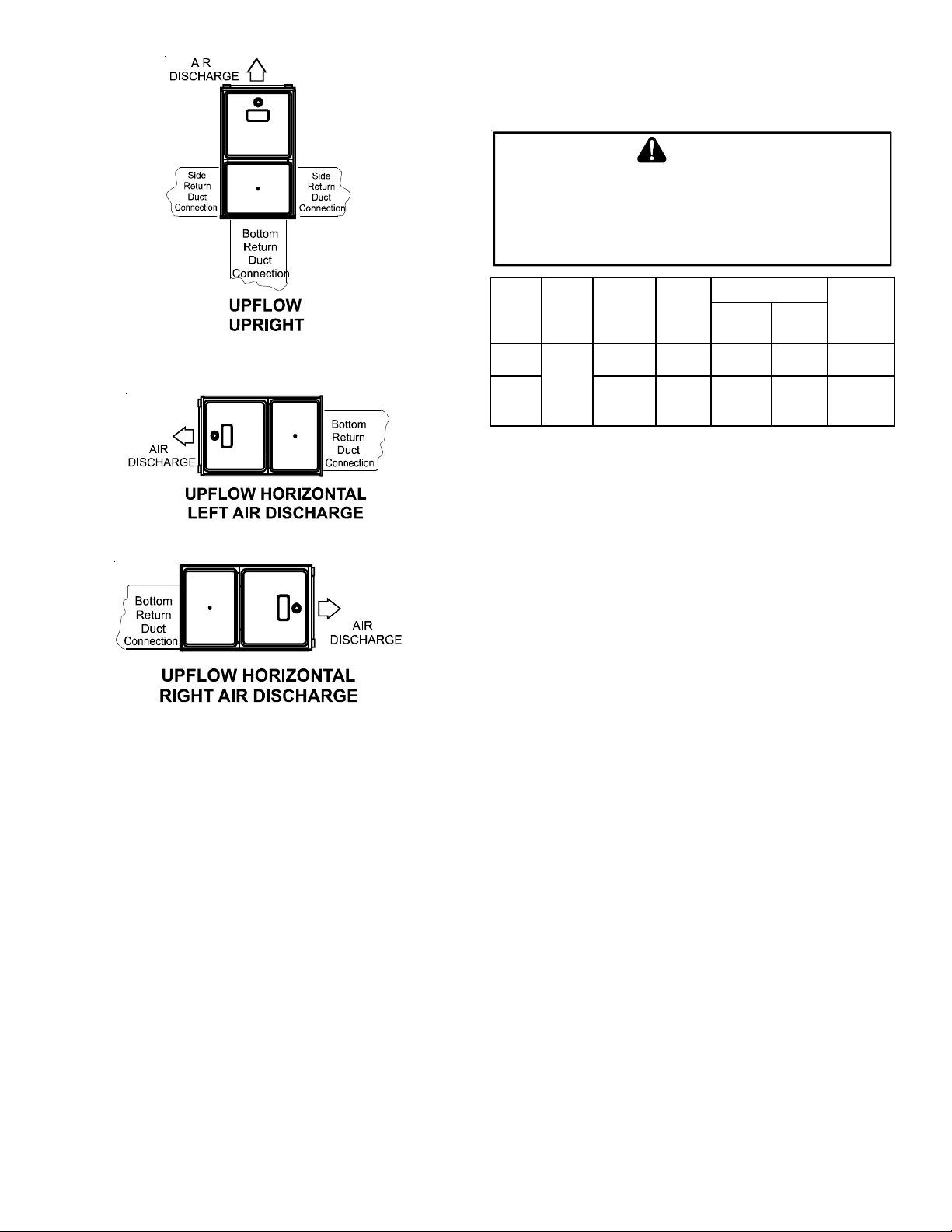
I
NSTALLATION POSITIONS
This furnace may be installed in an upright position or horizontal on either the left or right side panel. Do not install this
furnace on its back. For upright upflow furnaces, return air
ductwork may be attached to the side panel(s) and/or basepan.
For horizontal upflow furnaces, return air ductwork must be
attached to the basepan. For both upright or horizontal coun-
terflow furnaces, return ductwork must be attached to the
basepan (top end of the blower compartment). NOTE: Ductwork
must never be attached to the back of the furnace. Contact
your distributor for proper airflow requirements and number of
required ductwork connections. Refer to “Recommended Installation Positions” figure for appropriate installation positions,
ductwork connections, and resulting airflow arrangements.
H
ORIZONTAL APPLICATIONS
& C
ONSIDERATIONS
FRONT COVER PRESSURE SWITCH TUBE LOCATION
When a furnace is installed horizontally with left side down,
the front cover pressure switch tube must be re-located to
the lower port of the collector box cover.
1. Remove tube from front cover pressure switch and
collector box cover.
2. Remove rubber plug from bottom collector box port
and install on top collector box port.
3. Locate 24” x 1/4” tube in bag assembly.
4. Install one end on front cover pressure switch.
5. Route tube to lower port on collector box cover and
cut off excess tubing.
DRAIN TRAP AND LINES
In horizontal applications the condensate drain trap is secured to
the furnace side panel, suspending it below the furnace. A minimum clearance of 5.5” below the furnace must be provided for
the drain trap. Additionally, the appropriate downward piping
slope must be maintained from the drain trap to the drain location. Refer to Condensate Drain Trap and Lines for further de-
tails. If the drain trap and drain line will be exposed to temperatures near or below freezing, adequate measures must be taken
to prevent condensate from freezing.
2" 2" 3/8"
ANGLE IRON
XX
(3
PLACES
)
Figure 2
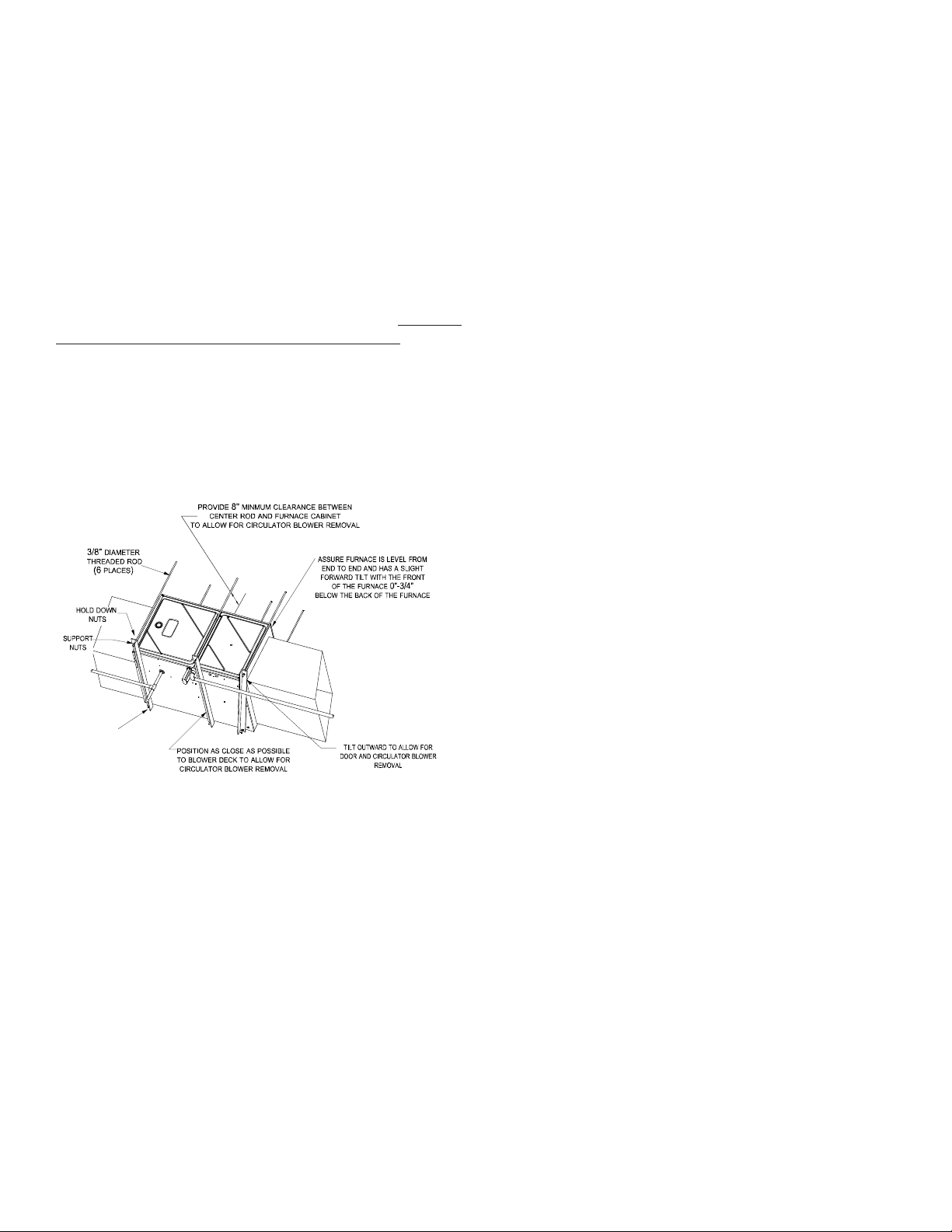
When installing a furnace horizontally, additional consideration
must be given to the following:
FURNACE S USPENSION
If suspending the furnace from rafters or joists, use 3/8" threaded
rod and 2”x2”x1/8” angle iron as shown in the following diagram. The length of rod will depend on the application and the
clearances necessary.
LEVELING
Leveling ensures proper condensate drainage from the heat exchanger. For proper flue pipe drainage, the furnace must be level
lengthwise from end to end. The furnace should have a slight
tilt from back to front with the access doors downhill fromthe
back panel approximately 1/2 to 3/4 inches. The slight tilt
allows the heat exchanger condensate, generated in the
recuperator coil, to flow forward to the recuperator coil frontcover.
ALTERNATE VENT/FLUE AND COMBUSTION AIR CONNECTONS
In horizontial installations provisions for alternate flue and
combustion air piping are available for upflow furnaces with
left discharge and counterflow furnaces with right air discharge. This configuration allows thye flue and combustion
air piping to be run vertically through the side of the furnace. Refer to the “Recommended Installation Positions” figure for further detail. The standard piping connections may
also be used in these positions. Refer to Vent/Flue Pipe and
Combustion Air Pipe for details concerning the conversion to
the alternate vent/flue and combustion air connections.
When using the horizontal alternate vent configuration, you
must use the RF000142 vent drain kit. See following illustration.
If the furnace is installed in a crawl space it must be suspended
from the floor joist or supported by a concrete pad. Never install
the furnace on the ground or allow it to be exposed to water.
9
Page 10
FREEZE PROTECTION
Refer to Horizontal Applications and Conditions - Drain Trap and
Lines.
WARNING
P
OSSIBLE PROPERTY DAMAGE, PERSONAL INJURY OR DEATH MAY
OCCUR IF THE CORRECT CONVERSION KITS ARE NOT INSTALLED
APPROPRIATE KITS MUST BE APPLIED TO ENSURE SAFE AND PROPER
FURNACE OPERATION
QUALIFIED INSTALLER OR SERVICE AGENCY
. ALL
CONVERSIONS MUST BE PERFORMED BY A
.
. THE
Alternate Vent/Flue Location
Figure 3A
Figure 3B
Figure 3C
Recommended Installation Positions
ALTERNATE ELECTRICAL AND GAS LINE CONNECTIONS
This furnace has provisions allowing for electrical and gas line
connections through either side panel. In horizontal applications
the connections can be made either through the “top” or “bottom” of the furnace.
Manifold P ress ure
Gas Altitude Kit Orifice
Nat ural No ne # 45 3.5" w.c. 1.9" w.c. No ne
0-7000
Propane LPM -07*
1
LPM -07* suppo rts bot h Honeywell and White-Rodgers 1-stage valves
In Canada, gas furnac es are o nly cert ified to 4500 feet.
NOTE:
P
ROPANE GAS/HIGH ALTITUDE INSTALLATIONS
1
1.25mm 10.0" w.c. 6.0" w.c. None
High
Stage
Low
Stage
Pressure
Swit ch
Change
This furnace is shipped from the factory configured for natural
gas at standard altitude. Propane gas installations require an
orifice and spring change to compensate for the energy content
difference between natural and propane gas.
High altitude installations may require both a pressure switch
and an orifice/spring change. These changes are necessary to
compensate for the natural reduction in the density of both the
gas fuel and the combustion air at higher altitude.
For installations above 7000 feet, please refer to the furnace
Specification Sheets for required kit(s).
For furnaces being converted to LP gas, it is strongly recommended that a LPLP03 kit also be installed. The use of this
kit will prevent the furnace from firing when the LP gas supply pressure is too low to support proper combustion.
Contact the distributor for a tabular listing of appropriate
manufacturer’s kits for propane gas and/or high altitude installations. The indicated kits must be used to insure safe and
proper furnace operation. All conversions must be performed by
a qualified installer, or service agency.
DRAIN PAN
A drain pan must be provided if the furnace is installed above a
conditioned area. The drain pan must cover the entire area
under the furnace (and air conditioning coil if applicable).
V
ENT/FLUE PIPE
& C
OMBUSTION AIR PIPE
This manual will refer to the pipe that discharges products
of combustion to the outdoors as the “vent” pipe or “flue”
pipe. The pipe that supplies air for combustion to the furnace will be referred to as the “intake” pipe or “combustion
air” pipe. A condensing gas furnace achieves its high level of
efficiency by extracting almost all of the heat from the products
of combustion and cooling them to the point where condensation
10
Page 11
takes place. Because of the relatively low flue gas temperature
and water condensation requirements, PVC or ABS pipe is typically used as venting and intake pipe materials. In Canada
ABS is not an approved vent pipe material but it is permissable
to use as combustion air pipe material.
In addition to PVC and ABS pipe and fittings, Innoflue® by
Centrotherm Eco Systems and PolyPro® by M&G Duravent are
also approved vent and combustion air materials for installations in the U.S.A. and Canada. Manufacturers Installation
instructions for these products must be followed. These products have specific instructions for installing, joining and terminating. Do not mix materials or components of one manufacturer with materials or components of another manufacturer.
All furnaces are manufactured with 2" vent / intake pipe and
connectors. For furnaces requiring installation of 3" pipe,
the transition from 2" to 3" should be done as close to the
furnace as practically possible.
This furnace must not be connected to Type B, BW, or L vent or
vent connector, and must not be vented into any portion of a
factory built or masonry chimney except when used as a pathway
for PVC as described later in this section. Never common vent
this appliance with another appliance or use a vent which is used
by a solid fuel appliance. Do not use commercially available “no
hub connectors” other than those shipped with this product.
It is the responsibility of the installer to follow the manufacturers’ recommendations and to verify that all vent/flue piping and
connectors are compatible with furnace flue products. Additionally, it is the responsibility of the installer to ensure that all piping
and connections possess adequate structural integrity and support to prevent flue pipe separation, shifting, or sagging during
furnace operation.
MATERIALS AND JOINING METHODS
Two-three-inch nominal diameter PVC Schedule 40 pipe meeting ASTM D1785, PVC primer meeting ASTM F656, and PVC
solvent cement meeting ASTM D2564 specifications must be
used. Fittings must be DWV type fittings meeting ASTM
D2665 and ASTM D3311. Carefully follow the manufacturer’s
instructions for cutting, cleaning, and solvent cementing of
PVC.
The use of Schedule 40 PVC cellular core DWV meeting ASTM
F891-1 or ABS cellular core (Foam Core) plastic pipe is also
acceptable as a flue/vent and intake pipe material. PVC
primer meeting ASTM F656 and PVC solvent cement meeting
ASTM D2564 specifications must be used. Fittings must be
DWV type fittings meeting ASTM D2665 and ASTM D3311.
Carefully follow the manufactures instructions for cutting,
cleaning and solvent cementing of PVC.
For Canadian installations; all PVC pipe, fittings and joining
materials must be UL S636 listed.
NOTE: Requirement does not apply to the combustion air
pipe.
As an alternative to PVC pipe, primer, solvent cement, and fittings, ABS materials which are in compliance with the following
specifications may be used. Two-or-three-inch ABS Schedule 40
pipe must meet ASTM D1527 and, if used in Canada, must be
CSA listed. Solvent cement for ABS to ABS joints must meet
ASTM D2235 and, if used in Canada, must be CSA listed. The
solvent cement for the PVC to ABS transition joint must meet
ASTM D3138. Fittings must be DWV type fittings meeting ASTM
D2661 and ASTM D3311 and, if used in Canada, must be CSA
listed. Carefully follow the manufacturers’ instructions for cutting, cleaning, and solvent cementing PVC and/or ABS.
WARNING
U
PON COMPLETION OF THE FURNACE INSTALLATION, CAREFULLY
INSPECT THE ENTIRE FLUE SYSTEM BOTH INSIDE AND OUTSIDE OF THE
FURNACE TO ASSURE IT IS PROPERLY SEALED
SYSTEM CAN RESULT IN SERIOUS PERSONAL INJURY OR DEATH DUE TO
EXPOSURE TO FLUE PRODUCTS, INCLUDING CARBO N MONOXIDE
. L
EAKS IN THE FLUE
.
WARNING
F
AILURE TO FOLLOW THESE INSTRUCTIONS CAN RESULT IN BODILY
INJURY OR DEATH
GIVEN IN THIS SECTION
. C
AREFULLY READ AND FOLLOW ALL INSTRUCTIONS
.
DUAL CERTIFICATION: NON-DIRECT/DIRECT VENT
This furnace is dual certified and may be installed as a non-direct
vent (single pipe) or direct vent (dual pipe) appliance. A non-
direct vent installation requires only a vent/flue pipe, while a
direct vent installation requires both a vent/flue pipe and a com-
bustion air intake pipe. Refer to the appropriate section for
details concerning piping size, length, number of elbows, furnace connections, and terminations.
All 90° elbows must be medium radius (1/4 bend DWV) or long
radius (Long sweep 1/4 bend DWV) types conforming to ASTM
D3311. A medium radius (1/4 bend DWV) elbow measures 3 1/
16” minimum from the plane of one opening to the center line of
the other opening for 2” diameter pipe, and 4 9/16” minimum
for 3” pipe.
PROPER VENT/FLUE AND COMBUSTION AIR PIPING PRACTICES
Adhere to these instructions to ensure safe and proper furnace
performance. The length, diameter, and number of elbows of the
vent/flue pipe and combustion air pipe (when applicable) affects
the performance of the furnace and must be carefully sized. All
piping must be installed in accordance with local codes and these
instructions.
WARNING
TO
AVOID BODILY INJURY, FIRE OR EXPLOSION, SOLVENT CEMENTS
MUST BE KEPT AWAY FROM ALL IGNITION SOURCES (I.E
FLAMES, AND EXCESSIVE HEAT) AS THEY ARE COMBUSTIBLE LIQUIDS
VOID BREATHING CEMENT VAPORS OR CONTACT WITH SKIN AND/OR
A
EYES
.
.,
SPARKS, OPEN
.
11
Page 12
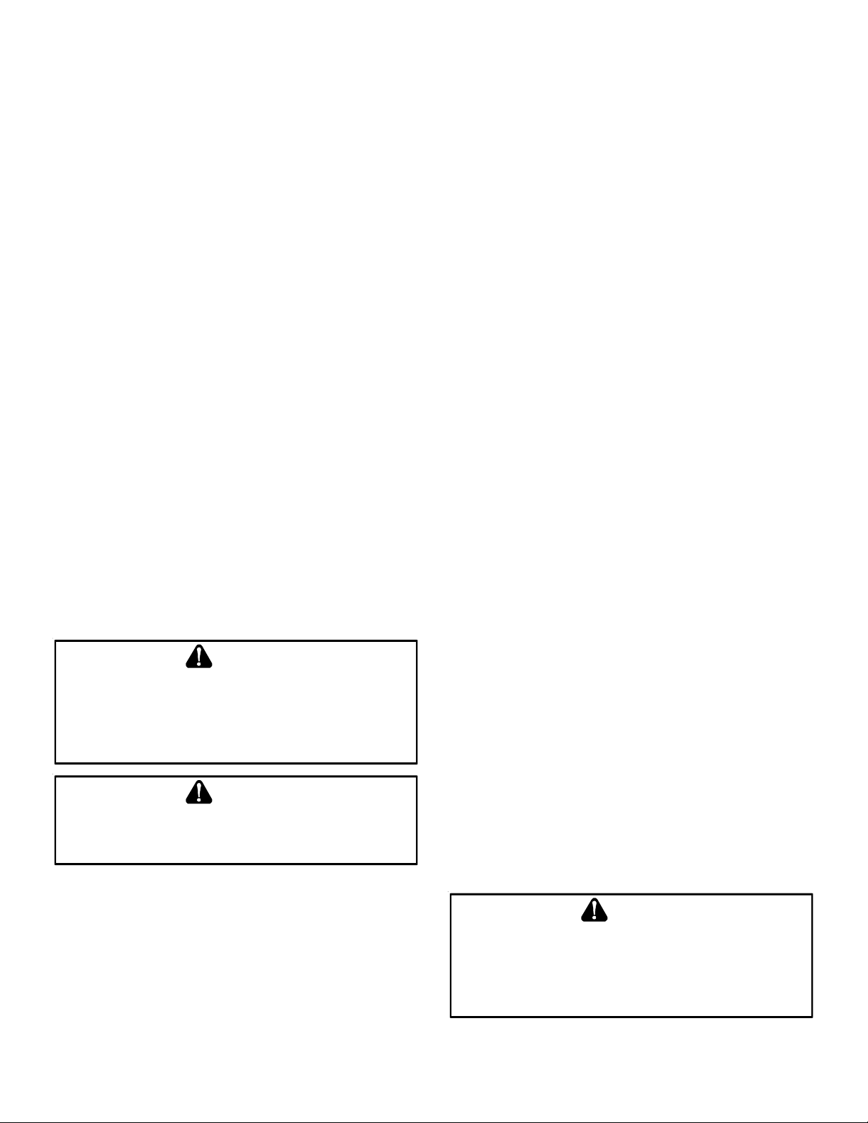
PREFERRED
Precautions should be taken to prevent condensate from freezing inside the vent/flue pipe and/or at the vent/flue pipe termination. All vent/flue piping exposed to freezing temperatures
below 35°F for extended periods of time must be insulated with
1/2” thick closed cell foam. Also all vent/flue piping exposed
outdoors in excess of the terminations shown in this manual (or
in unheated areas) must be insulated with 1/2” thick closed cell
foam. Inspect piping for leaks prior to installing insulation.
TERMINATION LOCATIONS
Figure 4
ACCEPTABLE
TRANSITION NO LESS
THAN 45 DEGREES TO
HORIZONTAL PLANE TO
AVOID CREATING A WATER
TRAP IN VENT PIPING.
Figure 5
NO TRANSITION ON
HORIZONTAL PLANE,
THIS CREATES A
WATER TRAP AND
RESTRICTS FLUE
GASES
Figure 6
Some models require the use of 3” pipe. Do not transition
from a 2” to 3” pipe in a horizontal section of pipe as this
may create a water trap.
Piping must be adequately secured and supported to prohibit
sagging, joint separation, and/or detachment from the furnace.
Horizontal runs of vent/flue piping must be supported every three
to five feet and must maintain a 1/4 inch per foot downward
slope, back towards the furnace, to properly return condensate
to the furnace’s drain system. Allowances should be made for
minor expansion and contraction due to temperature variations.
For this reason, particular care must be taken to secure piping
when a long run is followed by a short offset of less than 40
inches.
Non-Direct Vent
&
Direct Vent
Vent/Flue Terminations
Non-Direct Vent
Vent/Flue Termination
No Terminations
Above Walkway
Grade or Highest
Anticipated
Snow Leve l
3' min.
Forced Air
Inlet
<10'
12"
12" min.
12" min.
Direct Vent
Vent/Flue Termination
4' min.
4'
min.
12"
min.
Non-Direct Vent
Vent/Flue Termination
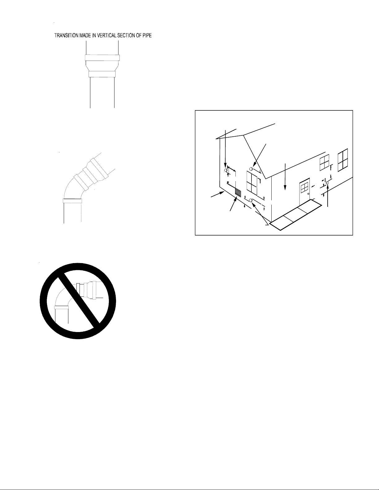
Vent Termination Clearances
Figure 7
NOTE: Refer to Location Requirements and Considerations for
combustion air contaminant restrictions.
The following bullets and diagram describe the restrictions concerning the appropriate location of vent/flue pipe and combustion air intake pipe (when applicable) terminations. Refer to
Non-Direct Vent (Single Pipe) Piping and Direct Vent (Dual Pipe)
Piping located in this section for specific details on termination
construction.
• All terminations (flue and/or intake) must be located
at least 12 inches above ground level or the
anticipated snow level.
• Vent terminations (non-direct and direct vent) must
terminate at least 3 feet above any forced air inlet
located within 10 feet.
NOTE: This provision does not apply to the combustion
air intake termination of a direct vent application.
• The vent termination of a non-direct vent application
must terminate at least 4 feet below, 4 feet horizontally
from, or 1 foot above any door, window, or gravity air
inlet into any building.
• The vent termination of a direct vent application must
terminate at least 12 inches from any opening through
which flue gases may enter a building (door, window, or
gravity air inlet).
12
Page 13
• The vent termination of vent pipe run vertically through
a roof must terminate at least 12 inches above the roof
line (or the anticipated snow level) and be at least 12
inches from any vertical wall (including any anticipated
snow build up).
• A vent termination shall not terminate over public
walkways
or over an area where condensate or vapor could create
a nuisance or hazard or could be detrimental to the
operation of regulators, relief valves, or other
equipment.
• The combustion air intake termination of a direct vent
application should not terminate in an area which is
frequently dusty or dirty.
NOTE: In Canada, the current edition of CAN/CSA B149.1-15
takes precendence over the preceding termination
restriction.
CANADIAN VENT PIPE & COMBUSTION AIR PIPE REQUIRE-
MENTS
All installations in Canada must conform to the requirements
of CAN/CSA B149.1 -15 code. All vent components, including
primer and cement, must be listed to ULC S636. The certified pipe and fittings should be clearly marked with the ULC
standard “S636”. The primer and cement used must be of
the same manufacturer as the vent system. For Royal Pipe
System 636; use GVS-65 Primer (Purple) and GVS-65 PVC
Solvent Cement. For IPEX System 636, use PVC/CPVC Primer,
Purple or clear. Use PVC Solvent Cement (Gray).
For Canadian installations, ABS may be used as a combustion air pipe only. ABS is not an approved vent material in
Canada. If ABS is used as a combustion air pipe, it must be
CSA certified. Always follow the manufacturer’s instructions
in the use of primer and cement. Do not use primer and
cement around potential sources of ignition. Do not use
primer or cement beyond its expiration date.
The safe operation, as defined by ULC S636, of the vent
system is based on following these installation instructions,
the vent system manufacturer’s installation instructions, and
proper use of primer and cement. It is recommended under
this standard, that the vent system be checked once a year
by qualified service personnel. All fire stops and roof flashings
used with this system must be UL listed. Acceptability under
CAN/CSA B149.1-15 is dependent upon full compliance with
all installation instructions. Consult the authority having
jurisdiction (gas inspection authority, municipal building department, fire department, etc.) before installation to determine the need to obtain a permit. *IPEX System 636™ is a
trademark of IPEX Inc.
Carefully follow the pipe manufacturers’ instructions for cutting,
cleaning, and solvent cementing PVC and/or ABS.
The vent can be run through an existing unused chimney provided the space between the vent pipe and the chimney is insulated and closed with a weather-tight, corrosion-resistant flashing.
STANDARD FURNACE CONNECTIONS
It is the responsibility of the installer to ensure that the piping
connections to the furnace are secure, airtight, and adequately
supported.
VENT/FLUE P IPE
The vent pipe outlet is sized to accept 2” pipe. Secure vent/
flue pipe directly into the furnace fitting with the appropriate glue. Alternately, a small section of 2" pipe may be glued
in the furnace socket and a rubber coupling installed to allow
removal for future service. Combustion Air and Vent piping
should be routed in a manner to avoid contact with refrigerant lines, metering devices, condensate drain lines, etc. If
necessary, clearances may be increased by creating an offset using two 45 degree elbows (Figure 8A).
45 DEGREE
ELBOWS
Increased Clearance Configuration
Figure 8A
This joint can be rotated on the fitting to establish maximum clearance between refrigerant lines, metering devices,
and condensate drain lines, etc. This joint is the equivalent
of one 90 deg. elbow when considering elbow count.
NOTE: For non-direct vent installations, a minimum of one
90° elbow should be installed on the combustion air intake
coupling to guard against inadvertent blockage.
WARNING
E
DGES OF SHEET METAL HOLES MAY BE SHARP
PRECAUTION WHEN REMOVING HOLE PLUGS
C
OMBUSTION AIR PIPE
DIRECT V ENT I NSTALLATIONS
On upflow units secure the combustion air intake pipe to the air
intake coupling by using a take apart rubber coupling supplied
with the furnace or a plastic coupling. Also, the intake coupling may be inverted to allow the intake pipe to be glued
directly to it. After inverting the coupling, secure it to the
furnace top with screws. On counterflow units secure the com-
bustion air intake pipe to the air intake coupling using the rubber
coupling and worm gear hose clamps provided with the unit. The
13
.
. USE
GLOVES AS A
Page 14
counterflow rubber coupling allows service removal of air intake
piping internal to the furnace blower compartment. The combustion air intake pipe can also be secured directly to the counterflow unit air intake pipe coupling.
VENT-DRAIN
Figure 8B
NON-DIRECT VENT INSTALLATIONS
A minimum of one 90° elbow should be installed on the combustion air intake “coupling” to guard against inadvertent blockage.
WARNING
THE
RUBBER ELBOW IS NOT DESIGNED TO SUPPORT A LOAD
RUBBER ELBOW IS MOUNTED EXTERNALLY TO THE FURNACE CABINET
EXTREME CARE MUST BE TAKEN TO ADEQUATELY SUPPORT FIELD
SUPPLIED VENT/FLUE PIPING, AS DAMAGE CAN RESULT IN LEAKS
CAUSING BODILY INJURY OR DEATH DUE TO EXPOSURE TO FLUE GASES
INCLUDING CARBON MONOXIDE
. W
HEN THE
,
-
,
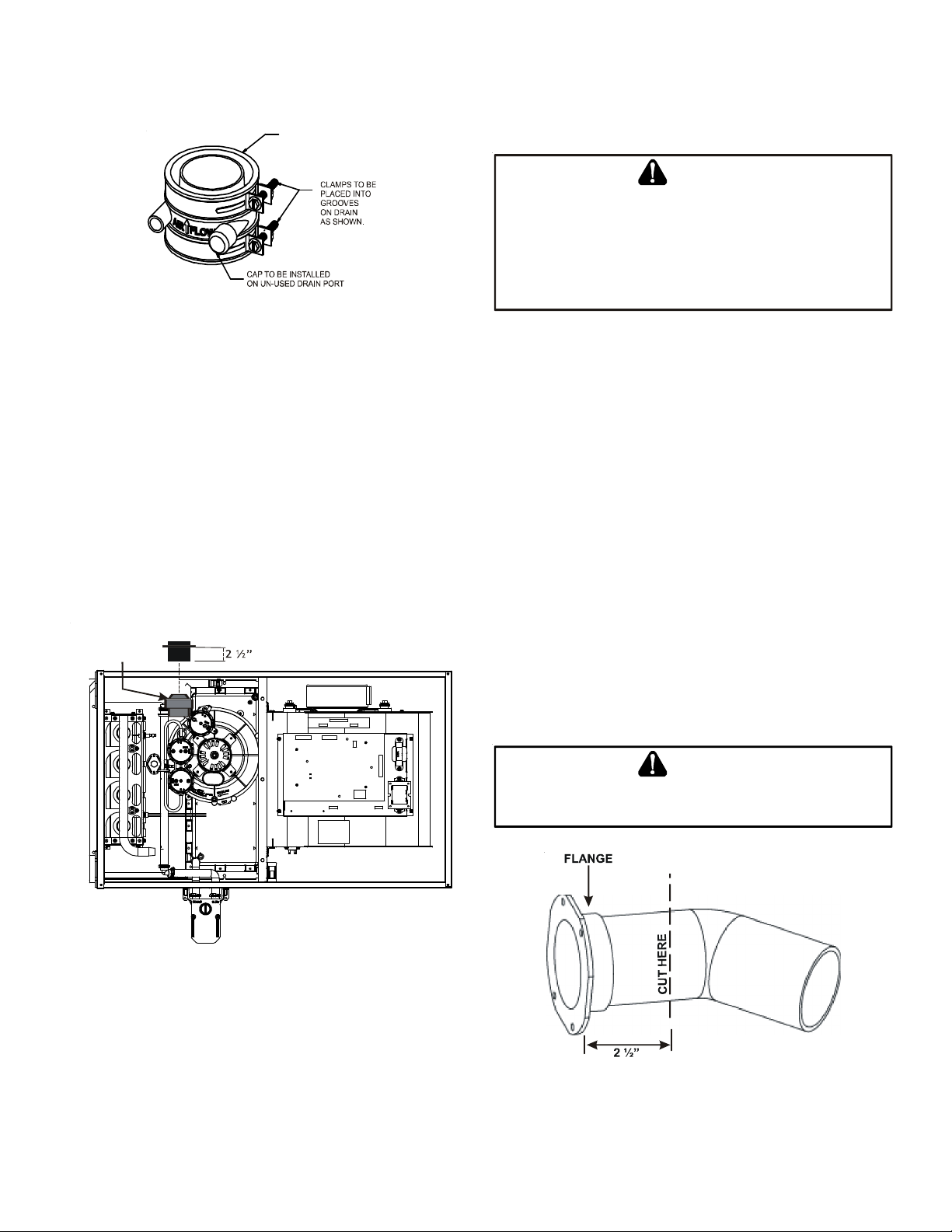
COMBUSTION AIR INTAKE OPTIONS: The RF000142 coupling
(Figure 8B) can be secured directly to the furnace intake
coupling if condensation is a concern. If the RF000142 is
used on the combustion air inlet, it must be installed with
the arrow pointing up. It should be noted, the combustion
air will actually be moving in a direction opposite of the
arrow on the RF000142 coupling. It must have a field supplied, trapped drain tube free-draining to proper condensate disposal location. A loop in the drain tube can serve as
a trap. The unused RF000142 drain fitting should be capped.
A tee installed in the intake pipe is also an acceptable method
of catching condensation. It must have a field supplied,
trapped drain tube or pipe, free-draining to proper condensate disposal location. A loop in the drain tube can serve as
a trap.
Insert flange. Cut 2 ½” long.
R 000142F
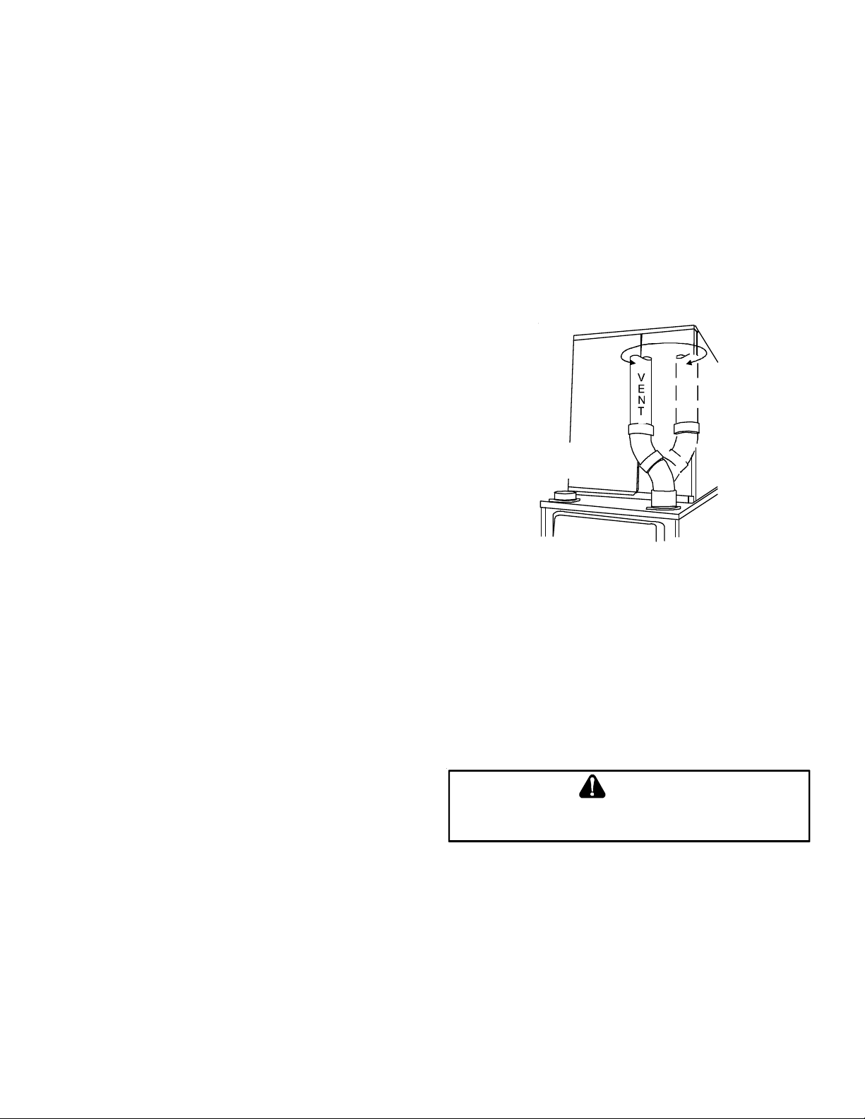
ALTERNATE VENT/FLUE LOCATION
The alternate vent/flue location is the large hole directly in line
with the induced draft blower outlet. To use the alternate vent/
flue location refer to the following steps and the “Alternate Vent/
Flue Location” figure. This option is not available with counterflow models.
NOTE: In the horizontal left installation position, a means of
condensate collection must be provided to keep vent pipe
condensate from entering the draft inducer housing. If the
vent drain elbow is eliminated from the installation, an
RF000142 kit must be used.
1. Remove the four screws from the vent pipe flange on
top the furnace.
2. Remove the internal elbow and vent pipe
3. Cut 2 1/2" from the flange .
4. Remove plastic plug in line with the inducer outlet
5. Install cut end of the flanged section and connect to
inducer with rubber coupling supplied with furnace.
6. Install screws removed in step 1 securing flange to
cabinet.
CAUTION
Figure 9
BE
SURE NOT TO DAMAGE INTERNAL WIRING OR OTHER COMPONENTS
WHEN REINSTALLING COUPLING AND SCREWS
Figure 10
14
.
Page 15
ALTERNATE COMBUSTION AIR PROVISION
(Upflow / Horizontal models only)
When using the alternate venting location, either in a horizontal left side down installation or a vertical installation
using down – venting, an alternate combustion air opening
can be used. A locating dimple is located on the right side of
the furnace cabinet. The locating dimple is 1 7/8" measured from the front edge of the cabinet in line with the
knock out. To use the alternate combustion air location:
1. Remove screws and combustion air flange from
cabinet.
2. Insert cabinet plug in unused combustion air hole.
3. Drill a pilot hole at the cabinet dimple (size dictated
by knockout tool used).
4. Use a knockout tool to create a 3" diameter hole
5. Install combustion air flange and secure with screws
removed in step one.
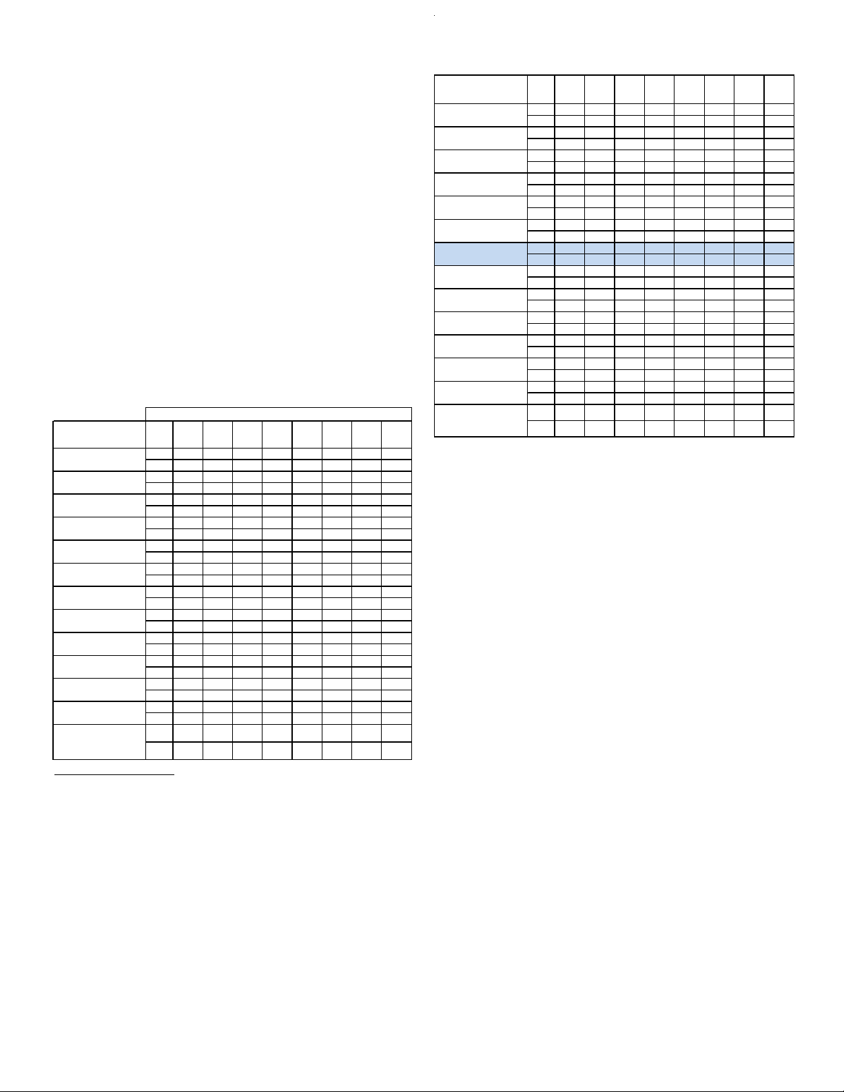
Number of Elbows
MODEL
*MSS920403AN
*MSS920402BN
*MSS920603BN
*MSS920803BN
*MSS920804CN
*MSS920805CN
*MSS921004CN
*MSS921005CN
*MSS921205DN
*CSS920402BN
*CSS920603BN
*CSS920804CN
*CSS921005CN
7,000 ft altitude or above use 3" pipe
*MSS920402BN - add 20' of 2" pipe for upflow position
^
*MSS920803BN - add 10' of 2" pipe f or upflow position, add 66' of 3" pipe f or upflow position
^
*MSS920804CN - add 25' of 2" pipe for upflow position, add 58' of 3" pipe for upf low position
^
PIPE
12345678
SIZE
2 7570656055504540
3 114 107 100 93 86 79 72 65
2^ 145 140 135 130 125 120 115 110
3 168 161 154 147 140 133 126 119
2 5550454035302520
3 127 120 113 106 99 92 85 78
30 25 20 15 10 5 N/A N/A
2
^
72 65 58 51 44 37 30 23
3
^
30 25 20 15 10 5 N/A N/A
2
^
72 65 58 51 44 37 30 23
3
^
40 35 30 25 20 15 10 5
2
^
3 7265585144373023
2 6055504540353025
3 168 161 154 147 140 133 126 119
2 3025201510 5N/AN/A
3 113 106 99 92 85 78 71 64
2 N/A N/A N/A N/ A N/A N/A N/A N/A
3 6558514437302316
2 100 95 90 85 80 75 70 65
3 137 130 123 116 109 102 95 88
2 6055504540353025
3 127 120 113 106 99 92 85 78
2 353025201510 5N/A
3 160 153 146 139 132 125 118 111
2 N/A N/A N/A N/ A N/A N/A N/A N/A
3 127 120 113 106 99 92 85 78
MODEL
*MSS960403AN
*MSS960402BN
*MSS960603BN
*MSS960803BN
*MSS960804CN
*MSS960805CN
*MSS961004CN
*MSS961005CN
*MSS961205DN
*CSS960402BN
*CSS960603BN
*CSS960804CN
*CSS961005CN
*CSS961205DN
PIPE
12345678
SIZE
2 7570656055504540
3 114 107 100 93 86 79 72 65
2 100 95 90 85 80 75 70 65
3 168 161 154 147 140 133 126 119
2 4540353025201510
3 168 161 154 147 140 133 126 119
35 30 25 20 15 10 5 N/A
2
^
3 168 161 154 147 140 133 126 119
2 6055504540353025
3 113 106 99 92 85 78 71 64
2 4540353025201510
3 120 113 106 99 92 85 78 71
2 N/A N/A N/A N/A N/A N/A N/A N/A
3 144 137 130 123 116 109 102 95
2 40353025201510 5
3 151 144 137 130 123 116 109 102
2 N/A N/A N/A N/A N/A N/A N/A N/A
3 158 151 144 137 130 123 116 109
2 100 95 90 85 80 75 70 65
3 137 130 123 116 109 102 95 88
2 4540353025201510
3 168 161 154 147 140 133 126 119
2 40353025201510 5
3 120 113 106 99 92 85 78 71
2 N/A N/A N/A N/A N/A N/A N/A N/A
3 113 106 99 92 85 78 71 64
2 N/A N/A N/A N/A N/A N/A N/A N/A
3 110 103 96 89 82 75 68 61
Non-Direct Vent (Single Pipe) Piping
Non-direct vent installations require only a vent/flue pipe. The
vent pipe can be run horizontally with an exit through the side of
the building or run vertically with an exit through the roof of the
building. The vent can also be run through an existing unused
chimney; however, it must extend a minimum of 12 inches above
the top of the chimney. The space between the vent pipe and the
chimney must be closed with a weather-tight, corrosion-resistant flashing.
Although non-direct vent installations do not require a combus-
tion air intake pipe, a minimum of one 90° elbow should be
attached to the furnace’s combustion air intake if: an upright
installation uses the standard intake location, or a horizontal
installation uses the alternate air intake location. This elbow will
guard against inadvertent blockage of the air intake.
VENT/FLUE PIPE LENGTHS AND DIAMETERS
(For Installations At or Above 7,000 Feet using 3” Venting)
NOTE: If either a 90 degree or 45 degree elbow is used for
termination, it must be pointed downward.
Refer to the Direct and Non-Direct Vent Table for applicable
length, elbows, and pipe diameter for construction of the vent/
flue pipe system of a non-direct vent installation. In addition to
the vent/flue pipe, a single 90° elbow should be secured to the
combustion air intake to prevent inadvertent blockage. The tee
used in the vent/flue termination must be included when determining the number of elbows in the piping system.
15
Page 16

VENT/FLUE PIPE T ERMINATIONS
A
NOTE: If either a 90 degree or 45 degree elbow is used for
termination, it must be pointed downward.
The vent/flue pipe may terminate vertically, as through a roof,
or horizontally, as through an outside wall.
Vertical vent/flue pipe terminations should be as shown in the
following figure. Refer to Vent/Flue Pipe and Combustion Air
Pipe - Termination Locations for details concerning location restrictions. The penetration of the vent through the roof must be
sealed tight with proper flashing such as is used with a plastic
plumbing vent.
Horizontal vent/flue pipe terminations should be as shown in the
following figure. Refer to Vent/Flue Pipe and Combustion Air
Pipe. To secure the pipe passing through the wall and prohibit
damage to piping connections, a coupling should be installed on
either side of the wall and solvent cemented to a length of pipe
connecting the two couplings. The length of pipe should be the
wall thickness plus the depth of the socket fittings to be installed
on the inside and outside of the wall. The wall penetration
should be sealed with silicone caulking material.
NOTE: Terminate both pipes in the same pressure zone
(same side of roof, no major obstacles between pipes,
etc.).
COMBUSTION AIR INTAKE
(OPTIONAL)
*Not requ ired for
single pipe installation
E
N
I
L
F
O
O
R
12” MIN TO ROOF OR
HIGHEST ANTICIPATED
SNOW LEVEL
TEE (OPTIONAL)
M
”
6
9
Figure 12
12” MIN
HEIGHT
DIFFERENCE
M
”
3
-
.
X
A
.
N
I
DOWN VENTING UPFLOW MODEL FURNACES ONLY
Combustion Air Pipe
Field Supplied
Drain Tee on Vent Pipe
w
a
r
C
/
t
n
e
m
e
s
a
B
ll piping and fittings must be joined per material manufacturers specifications
e
c
a
p
s
l
Condensate trapped
to prevent flue gas from escaping
and routed to field supplied
condensate disposal
to prevent separation and flue gas leaks.
Figure 11
Use alternate vent
& combination
air locations
Vent Pi pe
Floor
6’ Max.
1/4” per foot min.
slope to furnace
ELBOWS
STRAIGHT
Figure 13
12" MIN.
VENT/FLUE TEE (
TURNED DO WN or
90° ELBOW TURNED
1 2" MIN . ABOVE
HIGHEST ANTICIPATED
SNOW LEVEL
or
45° EL BOW
DOWN
OPTIONAL)
Horizontal Termination (Single Pipe)
Above Highest Anticipated Snow Level
Figure 14
16
Page 17

10”- 24”
6” MAX
4” MIN
90°
ELBOWS
3” - 24”
90º OR 45°
ELBOW
12" MIN. TO GRADE OR
HIGHEST ANTICIPATED
SNOW LEVEL
Standard Horizontal Terminations (Dual Pipe)
Figure 15
DIRECT VENT (DUAL PIPE) PIPING
Direct vent installations require both a combustion air intake
and a vent/flue pipe. The pipes may be run horizontally and exit
through the side of the building or run vertically and exit through
the roof of the building. The pipes may be run through an existing unused chimney; however, they must extend a minimum of
12 inches above the top of the chimney. The space between the
pipes and the chimney must be closed with a weather tight,
corrosion resistant flashing. Both the combustion air intake and
a vent/flue pipe terminations must be in the same atmospheric
pressure zone. Refer to Vent/Flue and Combustion Air Pipe -
Termination Locations or Concentric Vent Termination for specific details on termination construction. For details concerning
connection of pipes to the furnace, refer to the Vent/Flue Pipe
and Combustion Pipe - Standard Furnace Connections or Alter-
nate Furnace Connections.
12" MIN. ABOVE
HIGHEST ANTICIPATED
SNOW LEVEL
Alternate Horizontal Vent Termination (Dual Pipe)
Figure 16
VENT/FLUE & COMBUSTION AIR PIPE LENGTHS & DIAMETERS
Refer to the following table for applicable length, elbows, and
pipe diameter for construction of the vent/flue and combustion
air intake pipe systems of a direct vent (dual pipe) installation.
The number of elbows tabulated represents the number of elbows and/or tees in each (Vent/Flue & Combustion Air Intake)
pipe. Elbows and/or tees used in the terminations must be included when determining the number of elbows in the piping
systems.
If the combustion air intake pipe is to be installed above a finished ceiling or other area where dripping of condensate will be
objectionable, insulation of the combustion air pipe may be required.
90°
ELBOWS
3”-24” BETWEEN PIPES
17
12" MIN. ABOVE
HIGHEST ANT ICIPATED
SNOW LEVEL
Combustion Air Intake may also be snorkeled
to obtain 12” min ground clearance.
Alternate Vent Termination Above Anticipated Snow Level
(Dual Pipe)
Figure 17
Page 18

Use 1/2” thick closed cell foam insulation such as Armaflex™
or Insultube™ where required.
VENT/FLUE AND COMBUSTION AIR PIPE TERMINATIONS
The vent/flue and combustion air pipes may terminate vertically, as through a roof, or horizontally, as through an outside
wall.
Vertical pipe terminations should be as shown in the following
figure. Refer to Vent/Flue Pipe and Combustion Pipe - Termina-
tion Locations for details concerning location restrictions. The
penetrations through the roof must be sealed tight with proper
flashing such as is used with a plastic plumbing vent.
Vent & Combustion Air Intake Measurements for Standard
Horizontal Terminations (Dual Pipe)
Center to center = 10” min / 24” max.
Vertical separation: 0” - 24”
Vent termination from wall = 8” min / 12” max.
Combustion air intake from wall = 6” max.
Vent and intake clearance to ground or anticipated snow level
= 12” min.
3”MIN
24”MAX
12” MIN SEPARATION
3” MIN
12” MIN TO GRADE OR HIGHEST
ANTICIPATED SNOW LEVEL
Termination of Multiple Direct Vent Furnaces
Figure 18
VENT/INTAKE TERMINATIONS FOR INSTALLATION OF MULTIPLE
DIRECT VENT FURNACES
If more than one direct vent furnace is to be installed vertically
through a common roof top, maintain the same minimum clearances between the exhaust vent and air intake terminations of
adjacent units as with the exhaust vent and air intake terminations of a single unit.
If more than one direct vent furnace is to be installed horizontally through a common side wall, maintain the clearances as in
the following figure. Always terminate all exhaust vent outlets
at the same elevation and always terminate all air intakes at the
same elevation.
Horizontal Installation
Vertical Installation
Side Wall Vent Kit
Figure 19
CONCENTRIC VENT TERMINATION
Refer to the directions provided with the Concentric Vent Kit
(DCVK) for installation specifications.
SIDE WALL VENT KIT
This kit is to be used with 2” or 3” direct vent systems. The
vent kit must terminate outside the structure and may be installed with the intake and exhaust pipes located side-by-side or
with one pipe above the other. These kits are NOT intended for
use with single pipe (non-direct vent) installations.
Refer to the directions furnished with the Side Wall Vent Kit
(p/n 0170K00000S or 0170K00001S) for installation specifications.
C
ONDENSATE DRAIN LINES
A condensing gas furnace achieves its high level of efficiency by
extracting heat from the products of combustion to the point
where condensation takes place. The condensate must be collected in the furnace drain trap and routed to an appropriate
drain location in compliance with local and national codes.
Follow the bullets listed below when installing the drain system.
Refer to the following sections for specific details concerning
furnace drain trap installation and drain hose hook ups.
• The drain trap supplied with the furnace must be
used.
• The drain trap must be primed at time of
installation.
• The drain line between furnace and drain location
must meet local and nation codes.
• The drain line between furnace and drain location
must maintain a 1/4 inch per foot downward slope
toward the drain.
• Do not trap the drain line in any other location than at
the drain trap supplied with the furnace.
• If the drain line is routed through an area which may
see temperatures near or below freezing, precautions
must be taken to prevent condensate from freezing
within the drain line.
• If an air conditioning coil is installed with the furnace,
a common drain may be used. An open tee must be
installed in the drain line, near the cooling coil, to
relieve positive air pressure from the coil’s plenum.
This is necessary to prohibit any interference with the
function of the furnace’s drain trap.
& D
RAIN TRAP
18
Page 19

NOTE: In vertical installations, air conditioning coil condensate may drain into the furnace trap as long as there is a
trap between the coil and the furnace trap and the drain
pipe is not terminating below the water level of the furnace
trap.
Acceptable
area for
drain hole.
#1
#4
6
#
#2
#7
#9
#5
#11
Figure 20
#8
3
#
#10
Coupling
100 Degree
Elbow
NOTE: Drain components shown for information purposes only.
12”
3”
Side Cut-Out
Right side shown.
Figure 21
FIELD SUPPLIED DRAIN
Drain the furnace and air conditioning coil if applicable, in
compliance with code requirements. In horizontal or counterflow installations, a field installed rubber coupling will allow the drain trap to be removed for cleaning. The drain trap
must be primed before initial furnace start up. When an air
conditioning coil drain is connected to the field supplied furnace drain, it must be vented. An open tee must be installed
at a height no higher than the bottom of the furnace collector box to prevent air conditioning condensate from backing
up into the furnace, if the common drain was blocked.
UPFLOW MODEL INSTALLED VERTICALLY
The trap and factory installed hoses remain as shipped. The
furnace drain may exit either the right or left side of the
furnace cabinet. Both sides of the cabinet have two .875”
diameter holes which can be used interchangeably for drain
and low voltage wiring purposes. If a higher drain exit is
needed, a .875” diameter hole may be added in the area
shown in Figure 21. Any unused cabinet opening must be
sealed. Do not allow drain hose to sag or trap water.
GENERAL DRAIN INFORMATION
All furnace models come with a factory installed drain trap.
For vertical installations, the trap will remain in the factory
position except for a counterflow when the installer desires
the drain to exit the right side. All furnace models installed
horizontally require the trap to be relocated. Many drain
hoses have a built–in grommet which will provide a cabinet
seal when installed. See instructions below for your model
and installation position.
NOTE: Both sides of the drain trap must be primed prior
to initial furnace start up
DRAIN EXITING RIGHT SIDE
1. Locate and Install the 45º pipe / hose drain coupling
from the outside of the cabinet (barbed end goes in
the cabinet) through hole in the right side of the cabinet
and secure with two field supplied #8 self-tapping
screws (see Figure 22).
2. Locate the long drain hose #3 and cut at line “A” .
3. Install large end of hose #3 to trap outlet and secure
with 1.25" clamp.
19
Page 20

Hose #1
Hose #2
45 degree
barb-pipe
adapter
Installer selects right or left side drain
and installs this hose accordingly.
Figure 22
45 degree
barb-pipe
adapter
4. Install smaller end of hose #3 on 45º elbow and secure
with 1" clamp.
5. Refer to Field Supplied Drain section for instructions
on field supplied / installed drain on outlet of furnace
trap.
DRAIN EXITING LEFT SIDE
1. Install the 45 degree pipe / hose drain coupling from
the outside of the cabinet (barbed end goes in the
cabinet) through the hole in the left side of the cabinet
and secure with two field supplied #8 self-tapping
screws (see Figure 22).
2. Locate the long drain hose #3 and cut at “B” line for a
17.5" cabinet; cut at line “C” for a 21" cabinet; do not
cut for a “D” width cabinet.
3. Install large end of hose #3 to trap outlet and secure
with 1.25" clamp.
4. Install smaller end of hose #3 on 45º elbow and secure
with 1" clamp.
5. Refer to Field Supplied Drain section for instructions
on field supplied / installed drain on outlet of furnace
trap.
Hose #11
Figure 23
Hose #2
UPFLOW MODEL INSTALLED HORIZONTALLY WITH RIGHT SIDE
DOWN
Minimum 5 1/2" clearance is required for the drain trap beneath the furnace.
1. Remove the clamps from both ends of the drain hoses.
2. Remove the two screws holding the drain trap to the
blower deck.
3. Remove the trap and two hoses from the blower deck
4. Remove the two plugs from the right side of the cabinet
and install them in the blower deck.
5. (Draining the Vent Elbow ) Locate hose #2 (factory
installed) and cut 1” away from the 45 degree bend,
discard the 45 degree section. Insert hose #2 from
outside the cabinet through the cabinet drain hole
nearest the top, secure it to the barbed fitting in the
elbow with a red clamp.
6. For models *MSS920403AN and *MSS960403AN; locate
the hose #2 (factory installed) and cut 1.5 length from
the end of the hose. Insert hose #2 from outside the
cabinet through the cabinet’s drain hole nearest to
the top. Secure it to the barbed fitting in the elbow
with a red clamp.
7. (Draining the Collector Box) Install the non-grommet
end of hose #11 from outside the cabinet in the bottom
drain hole. Install on collector box and secure with a
silver clamp.
8. Use two silver clamps and secure the hoses to drain
trap. The trap outlet faces the front of the furnace.
Secure the trap to the cabinet using two screws
removed in step 2 by inserting the two screws through
the large set of holes in the top mounting tabs of the
trap into the two predrilled holes in the side of the
cabinet.
9. Refer to Field Supplied Drain section for instructions
on field supplied / installed drain on outlet of furnace
trap.
20
Page 21

UPFLOW MODEL INSTALLED HORIZONTALLY WITH LEFT SIDE
DOWN
Minimum 5 1/2" clearance is required for the drain trap beneath the furnace.
*Also see Front Cover Pressure Switch Tube Location on page
10.
1. Remove the clamps from the two drain tubes on the trap.
2. Remove the two screws holding the drain trap to the
blower deck.
3. Remove the trap and hoses from the blower deck.
Hose #6
Hose #5
4. Remove the two plugs from the left side of the cabinet
and install them in the blower deck.
5. (Draining the Vent Elbow) Locate hose #6. Measuring
from the non-grommet end; cut off and discard 1 ½”
for a “D” width cabinet, 5” for a “C” width cabinet, 8
½” for a “B” width cabinet.
6. Remove the rubber plug from vent – drain elbow side
port. Place hose #6 on the vent – drain elbow side port
and secure with a silver clamp .
7. Unused vent-drain elbow drip leg port must be sealed
to prevent flue gases from escaping. Insert the rubber
plug removed in step 6 into the unused elbow drain
port. Inserting a blunt tool such as a 3/16’’ Allen wrench
into the center of the rubber plug will stretch the plug
and allow complete insertion.
8. Locate hose #5 and cut 3” from the non-grommet end.
Discard the section without the grommet.
9. Insert the cut end of tube #5 through the lower cabinet
drain hole.
10. Connect hose #6 & hose #5 using 100º elbow and secure
with two red clamps
11. (Draining the Collector Box) Remove cap from left side
collector box drain port (bottom in horizontal left position)
and install it on right side (top) collector box drain port.
Hose #11
Figure 24
12. Install the non-grommet end of hose #11 from outside
the cabinet in the upper drain hole. Install on collector
box and secure with a silver clamp.
13. Use two silver clamps and secure the hoses to drain trap.
The trap outlet faces the front of the furnace. Secure
the trap to the cabinet using two screws removed in
step 2 by inserting the two screws through the large set
of holes in the top mounting tabs of the trap into the
two predrilled holes in the side of the cabinet. [Removed:
Place cap on vent...]
14. Refer to Field Supplied Drain section for instructions on
field supplied / installed drain on outlet of furnace trap.
UPFLOW MODEL INSTALLED HORIZONTALLY WITH LEFT SIDE
DOWN - ALTERNATE
*Also see Front Cover Pressure Switch Tube Location on
Page 10.
1. (Draining the RF000142 Coupling) Locate hose #2
(factory installed). Cut off and discard the 45° radius
end.
2. Install 90°radius end of hose #2 on RF000142 drain
outlet and secure with a red clamp.
3. Insert coupling in hose #2 and secure with a red clamp.
4. Locate hose #5 and cut 3” from the non-grommet end.
Discard the section without the grommet.
5. Insert the cut end of tube #5 through the lower cabinet
drain hole.
6. Insert 100 degree elbow in the cut end of hose #5.
7. Locate hose #6. Using red clamps, connect between
the coupling and 100 degree elbow, cutting off excess
tubing.
8. (Draining the Collector Box) Remove cap from left side
collector box drain port (bottom in horizontal left
position) and install it on right side (top) collector box
drain port and secure with a red clamp.
9. Install the non-grommet end of hose #11 from outside
the cabinet in the upper drain hole. Install on collector
box and secure with a silver clamp.
10. Use two silver clamps and secure the hoses to drain
trap. The trap outlet faces the front of the furnace.
Secure the trap to the cabinet using two screws
removed in step 2 by inserting the two screws through
the large set of holes in the top mounting tabs of the
trap.
21
Page 22

Insert flange. Cut 2 ½” long.
R 000142F
Figure 25
COUNTERFLOW MODEL INSTALLED VERTICALLY
DRAIN EXITING RIGHT SIDE (SEE FIGURE 27)
1. Remove hose clamps and hoses from trap.
2. Remove trap.
3. (Draining the Vent Elbow) Insert the non-grommet end
hose #10 into the cabinet back drain hole. Insert a
coupling into the drip leg of the vent-drain elbow and
secure with a silver clamp. Secure hose #10 on vent drain elbow barb fitting with a silver clamp.
4. (Draining the Collector Box) Insert non-grommet end of
hose #9 into the cabinet front drain hole and secure on
collector box drain port with a silver clamp.
5. Mate the drain trap inlets to the hoses and secure with
silver clamps.
6. Line up the trap mounting holes with the pre-drilled holes
in the furnace and secure with 2 screws removed in step
2.
7. Refer to Field Supplied Drain section for instructions on
field supplied / installed drain on outlet of furnace trap.
The furnace drain may exit the right or left side of the furnace cabinet (left side preferred) Trap and factory installed
hoses remain as shipped if the drain will exit the left side of
the cabinet. Draining from the right side requires relocation
of the trap to outside the cabinet.
DRAIN EXITING LEFT SIDE (SEE FIGURE 26)
1. Install a field supplied rubber coupling secured with a
1 1/4” clamp to enable removing the trap for future
cleaning. Alternately, a PVC fitting may be glued on
the trap outlet.
2. Install drain per local and National codes.
Figure 27
WARNING
HIGH VOLTAGE !
TO
AVOID PERSONAL INJURY OR DEATH DUE TO
ELECTRICAL SHOCK, DISCONNECT ELECTRICAL POWER
BEFORE SERVICING OR CHANGING ANY ELECTRICAL
WIRING
.
CAUTION
L
ABEL ALL WIRES PRIOR TO DISCONNECTION WHEN SERVICING
CONTROLS
OPERATION
. W
IRING ERRORS CAN CAUSE IMPROPER AND DANGEROUS
. V
ERIFY PROPER OPERATION AFTER SERVICING
.
Hose #4 x 3
Figure 26
Hose #5
WARNING
HIGH VOLTAGE !
TO
AVOID THE RISK OF ELECTRICAL SHOCK, WIRING TO
THE UNIT MUST BE POLARIZED AND GROUNDED
22
.
Page 23

COUNTERFLOW MODEL INSTALLED HORIZONTALLY WITH
RIGHT SIDE DOWN (SEE FIGURE 28)
Minimum 5 1/2” clearance is required for the drain trap
beneath the furnace.
NOTE: For horizontal installations, some of the required hoses
are found in the factory-installed hose assemblies. Remove
the hose clamps to obtain the respective hoses needed for
installation, and install per the following directions.
1. Remove the drain trap and factory installed drain tube
assemblies.
2. Remove two 1’’ plugs from right side of cabinet.
3. (Draining the Collector Box) From outside the cabinet,
insert the non-grommet end hose #7 into the back drain
hole and secure to collector box drain port using a silver
clamp.
4. (Draining the Vent Elbow) Insert the straight barbed
coupling into the vent - drain elbow drip leg and secure
with a red clamp.
1. Remove the factory installed drain trap and hose
assemblies. Leave the 100° elbow inserted and
clamped in the vent-drain elbow.
2. Remove two 1”plugs from left side of cabinet
3. (Draining the Collector Box) Remove the cap from the
left side of the collector box drain port (bottom in
horizontal left position) and install it on right side drain
port.
4. Place radius end of hose #4 (factory installed) on the
collector box drain port and secure with a silver clamp.
5. Insert hose #2 from outside the cabinet in the front
drain hole.
6. Connect hose #4 & hose #2 together using a straight
barbed coupling and two gold clamps (factory installed).
7. (Draining the Vent Elbow) Remove rubber plug from
vent – drain elbow side port.
8. The unused vent-drain elbow drip leg port must be
plugged to prevent flue gases from escaping. Insert
rubber plug removed in step 7 into the 100° elbow.
(Inserting a blunt tool such as a 3/16’’ Allen wrench
into the center of the rubber plug will stretch the plug
and allow complete insertion)
Hose #4
Hose #8
Hose #7
Hose #7
Figure 28
5. From outside the cabinet, insert the non-grommet end
of hose #8 into the front cabinet drain hole and secure
on the vent - drain elbow barb fitting using a red clamp.
6. Place the drain hoses on the trap inlets and secure with
silver clamps. The outlet of the trap must face the
original botom of furnace.
7. Using the two sheet metal screws provided in the cabinet,
secure the trap to the furnace.
8. Refer to Field Supplied Drain section for instructions on
field supplied/installed drain on outlet of furnace trap.
Hose #7
COUNTERFLOW MODEL INSTALLED HORIZONTALLY WITH LEFT
SIDE DOWN (SEE FIGURE 29)
Minimum 5 1/2" clearance is required for the drain trap beneath the furnace.
*Also see Front Cover Pressure Switch Tube Location on page
10.
Hose #4
9. Place radius end of hose #4 on the side port of vent –
drain elbow and secure with a gold clamp.
10. Insert a ½” diameter PVC pipe (factory installed) into
hose #4 and secure with a gold clamp.
11. Insert the non-grommet end of hose #5 (factory
installed) from outside the cabinet in the back drain
hole.
12. Insert 100º elbow in hose #5 and secure with a red
clamp.
Hose #5
Figure 29
Hose #2
23
Page 24

13. Locate hose #4 and cut a cut off a 4” straight section
and discard the radius end.
14. Connect the 4” straight section of hose #4 to the
100º elbow and the PVC pipe and secure with red
clamps.
15. Connect the hoses to the trap inlets and secure with
silver clamps, drain trap outlet must point to the
original bottom
of the furnace.
16. Using the two sheet metal screws provided in the
cabinet, secure the trap to the furnace.
17. Refer to Field Supplied Drain section for instructions on
field supplied / installed drain on outlet of furnace trap.
E
LECTRICAL CONNECTIONS
Line polarity must be observed when making field connections.
Line voltage connections can be made through either the right
or left side panel. The furnace is shipped configured for a left
side (right side for counterflows) electrical connection with the
junction box located inside the burner compartment. To make
electrical connections through the opposite side of the furnace,
the junction box must be relocated to the other side of the
burner compartment prior to making electrical connections. To
relocate the junction box, follow the steps shown in the Junction Box Relocation section.
WARNING
E
DGES OF SHEET METAL HOLES MAY BE SHARP
PRECAUTION WHEN REMOVING HOLE PLUGS
.
. USE
GLOVES AS A
WIRING HARNESS
The wiring harness is an integral part of this furnace. Wires
are color coded for identification purposes. Refer to the wiring
diagram for wire routings. If any of the original wire as supplied with the furnace must be replaced, it must be replaced
with wiring material having a temperature rating of at least
105° C. Any replacement wiring must be a copper conductor.
115 VOLT LINE CONNECTIONS
Before proceeding with electrical connections, ensure that the
supply voltage, frequency, and phase correspond to that specified on the unit rating plate. Power supply to the furnace must
be NEC Class 1, and must comply with all applicable codes. The
furnace must be electrically grounded in accordance with local
codes or, in their absence, with the latest edition of The National Electric Code, ANSI NFPA 70 and/or The Canadian Electric Code CSA C22.1.
WARNING
HIGH VOLTAGE !
TO
AVOID PERSONAL INJURY OR DEATH DUE TO
ELECTRICAL SHOCK, DISCONNECT ELECTRICAL POWER
BEFORE SERVICING OR CHANGING ANY ELECTRICAL
WIRING
.
Humidifier 1.0 Am p maximum at 120 VA C
Elec tronic A ir Cleaner 1.0 Amp maximum at 120 VAC
Use a separate fused branch electrical circuit containing properly sized wire, and fuse or circuit breaker. The fuse or circuit
breaker must be sized in accordance with the maximum
overcurrent protection specified on the unit rating plate. An
electrical disconnect must be provided at the furnace location.
Connect hot, neutral, and ground wires as shown in the wiring
diagram located on the unit’s blower door. For direct vent
applications, the cabinet opening to the junction box must be
sealed air tight using either an UL approved bushing such as
Heyco Liquid Tight or by applying non-reactive UL approved
sealant to bushing.
WARNING
TO
PREVENT PERSONAL INJURY OR DEATH DUE TO ELECTRIC SHOCK
DISCONNECT ELECTRICAL POWER BEFORE INSTALLING OR SERVICING THIS
UNIT
.
,
WARNING
HIGH VOLTAGE !
TO
AVOID THE RISK OF INJURY, ELECTRICAL SHOCK OR
DEATH, THE FURNACE MUST BE ELECTRICALLY
GROUNDED IN ACCORDANCE WITH LOCAL CODES OR IN
THEIR ABSENCE, WITH THE LATEST EDITION OF THE
N
ATIONAL ELECTRIC CODE
.
WARNING
TO
AVOID THE RISK OF INJURY, ELECTRICAL SHOCK OR DEATH, THE
FURNACE MUST BE ELECTRICALLY GROUNDED IN ACCORDANCE WITH
LOCAL CODES OR, IN THEIR ABSENCE, WITH THE LATEST EDITION OF THE
ATIONAL ELECTRICAL CODE
N
.
115 VOLT LINE VOLTAGE CONNECTION OF ACCESSORIES
(HUMIDIFIER AND ELECTRONIC AIR CLEANER - 96% MODELS
ONLY)
The furnace integrated control module is equipped with line voltage accessory terminals for controlling power to an optional fieldsupplied humidifier and/or electronic air cleaner.
The accessory load specifications are as follows:
Turn OFF power to the furnace before installing any accessories.
Follow the humidifier or air cleaner manufacturers’ instructions
for locating, mounting, grounding, and controlling these accessories. Accessory wiring connections are to be made through the
1/4" quick connect terminals provided on the furnace integrated
24
Page 25

control module. The humidifier and electronic air cleaner hot
terminals are identified as HUM and EAC. The humidifier and
electronic air cleaner neutral terminals are identified as NEUTRAL. All field wiring must conform to applicable codes. Connections should be made as shown. (See Figure 29.)
If it is necessary for the installer to supply additional line voltage
wiring to the inside of the furnace, the wiring must conform to
all local codes, and have a minimum temperature rating of 105°C.
All line voltage wire splices must be made inside the furnace
junction box.
The integrated control module single humidifier terminal (HUM)
is energized with 115 volts whenever the induced draft blower is
energized. This terminal can also be used to provide 115 volt
power to a humidifier transformer. The remaining primary
transformer wire would be connected to the Line N on the
control board. The integrated control module electronic air
cleaner terminals (EAC) are energized with 115 volts whenever
the circulator blower is energized.
NOTE: Wire routing must not to interfere with circulator blower
operation, filter removal, or routine maintenance.
JUNCTION BOX RELOCATION
This furnace is equipped with a blower door interlock switch
which interrupts unit voltage when the blower door is opened
for servicing. Do not defeat this switch.
24 VOLT THERMOSTAT WIRING
Low voltage connections can be made through either the right or
left side panel. Thermostat wiring entrance holes are located in
the blower compartment. The following figure shows connections for a “heat/cool system”.
This furnace is equipped with a 40 VA transformer to facilitate
use with most cooling equipment. Consult the wiring diagram,
located on the blower compartment door, for further details of
115 Volt and 24 Volt wiring.
WARNING
HIGH VOLTAGE !
TO
AVOID PERSONAL INJURY OR DEATH DUE TO
ELECTRICAL SHOCK, DISCONNECT ELECTRICAL POWER
BEFORE SERVICING OR CHANGING ANY ELECTRICAL
WIRING
.
LINE VOLTAGE CONNECTIONS CAN BE MADE THROUGH EITHER THE RIGHT
LEFT SIDE PANEL. THE FURNACE IS SHIPPED CONFIGURED FOR A LEFT
OR
ELECTRICAL CONNECTION. TO MAKE ELECTRICAL CONNECTIONS
SIDE
THROUGH
BE
CONNECTIONS
FOLLOWING
THE OPPOSITE SIDE OF THE FURNACE, THE JUNCTION BOX MUST
RELOCATED TO THE LEFT SIDE PRIOR TO MAKING ELECTRICAL
. TO RELOCATE THE JUNCTION BOX, PERFORM THE
STEPS.
1. Remove the burner compartment door.
2. Remove and save the two screws securing the junction
box to the side panel.
3. Relocate junction box and associated plugs and grommets
to opposite side panel. Secure with screws removed in
step
IMPORTANT NOTE
W
IRE ROUTING MUST NOT INTERFERE WITH CIRCULATOR BLOWER
OPERATION, FILTER REMOVAL OR ROUTINE MAINTENANCE
.
To ensure proper unit grounding, the ground wire should run
from the furnace ground screw located inside the furnace junction box all the way back to the electrical panel. NOTE: Do not
use gas piping as an electrical ground. To confirm proper unit
grounding, turn off the electrical power and perform the following check.
1. Measure resistance between the neutral (white) connection
and one of the burners.
2. Resistance should measure 10 ohms or less.
SINGLE-STAGE HEATING THERMOSTAT APPLICATION
A single-stage thermostat with only one heating stage is
needed to control this furnace.
Figure 30
FOSSIL FUEL APPLICATIONS
This furnace can be used in conjunction with a heat pump in a
fossil fuel application. A fossil fuel application refers to a combined gas furnace and heat pump installation which uses an outdoor temperature sensor to determine the most cost efficient
means of heating (heat pump or gas furnace).
Strictly follow the wiring guidelines in the fossil fuel kit installation instructions. All furnace connections must be made to the
furnace two-stage integrated control module and the “FURNACE”
terminal strip on the fossil fuel control board.
25
Page 26

PARK
PARK
E13
E11
K3
1
W
E9
R82
W22
K2
HEAT
E8
COOL
E1
W13
R35
R
HT OFF DLY
150
CUT
100
SW1.1
FOR
SECSEC
SW1.2
SW1.3
SW1.4
R9
SW2
FAULT
R522
RECALL
W27
R24
R12
5206A
R6
R15
W3
R16
DS1
R23
R18
R17
R11
CONDENSOR
CONTACTOR
COILS
NOTES:
1. ISOLATING RELAY MAY BE ELIMINATED IF LINE VOLTAGE
SUPPLY TO FURNACES IS THE SAME PHASE .
TO VERIFY PHASING:
A) VERIFY SOURCE IS EXACTLY THE SAME EITHER
L1, L2, OR L3 FROM THE SAME TRANSFORMER OR
B) CHECK WITH SCOPE OR PHASE METER
C) IF IN DOUBT USE RELAY
2. IF ISOLATING RELAY IS NOT USED, CONNECT FURNACE
LINE-H
EAC-H
E10
E29
RV1
W21
C15
FP
E14
E32
1VDC=1UA
R36
R39
R43
W20
R49
W18
R2
1
R3
R29
U1
TP14
R558
TP12
W11
PARK
XFMR-H
E16
E15
K1
W16
W9
R52
R51
R50
Q9
E12
R70
R90
6
R69
R67
R57
W19
L1
R53
R63
R41
W14
R44
W10
R27
R33
HUM-H
E28
K6
W26
W12
C14
R79
R81
R78
W32
R74
W28
W29
R95
R61
R75
F1
W4
CR13
W5
E33
R54
RV2
K4
W8
C11
C13
E31
W6
E17
E25
E18
E19
1
E20
E21
2
E23
K5
R73
R94
E34
W2
3
6
RV3
W7
LINE NEUTRAL
E24
R60
R58
W24
E30
TWINNING
R91
W30
E22
1
2
45
89
7
1112
10
AUTOMATIC IGNITI ON SYSTEM
R65
R13
W25
E7
CGRWY
PARK
E13
E11
K3
1
W
E9
R82
W22
K2
HEAT
E8
COOL
E1
W13
R35
R
HT OFF DL Y
150
CUT
100
SW1.1
FOR
SEC
SEC
SW1.2
SW1.3
SW1.4
SW2
FAULT
R522
RECALL
W27
R24
R12
5206A
RELAY
R6
R15
W3
R16
R23
R18
R17
R11
ISOLATING
(SEE NOTES)
R9
LINE-H
EAC-H
E10
E29
RV1
W21
C15
FP
E32
1VDC=1UA
R36
R39
R43
W20
R49
W18
R2
1
R3
R29
TP14
R558
DS1
TP12
W11
XFMR-H
E16
E15
K1
W16
W9
R52
E14
R51
R50
Q9
E12
R70
R90
6
R69
R67
R57
W19
L1
R53
R63
U1
R41
W14
R44
W10
R27
R33
HUM-H
E28
K6
W26
W12
C14
R79
R81
R78
W32
R74
W28
W29
R95
R61
R75
F1
W4
CR13
W5
E33
R54
RV2
K4
W8
C11
C13
E31
W6
E17
E25
E18
E19
1
E20
E21
2
E23
K5
R73
R94
E34
W2
3
6
RV3
W7
LINE NEUTRAL
E24
R60
R58
W24
E30
TWINNING
R91
W30
E22
1
2
45
89
7
1112
10
AUTOMATIC IGNITION SYSTEM
R65
R13
W25
E7
CGRWY
CGRWY
ROOM THERMOSTAT
TWINNING
Furnaces may be twinned without the use of a twinning
kit. Furnaces must be the same model and equipped with
PCBBF140 control boards. Follow the diagram provided in
this manual. Connection of the “twin” terminals of each
control together will allow simultaneous operation of two
or more furnace indoor blowers to operate synchronously
on a common duct system. Field installed low voltage
thermostat wiring, 3/16" terminals are required to make
this connection. An isolating relay (24 VAC coil & N/O
SPST) contacts is also required if the furnaces are not fed
from the same line voltage phase. A pulsing DC signal is
used to share the call for fan operation between furnaces.
The duration of the pulse width determines the speed that
the reading control will energize its blower motor.
CAUTION
TO
PREVENT UNRELIABLE OPERATION OR EQUIPMENT DAMAGE, THE
GAS MANIFOLD PRESSURE MUST BE AS SPECIFIED ON THE UNIT RATING
PLATE
. O
NLY MINOR ADJUSTMENTS SHOULD BE MADE BY ADJUSTING
THE GAS VALVE PRESSURE REGULATOR
.
WARNING
P
OSSIBLE PROPERTY DAMAGE, PERSONAL INJURY OR DEATH MAY
OCCUR IF THE CORRECT CONVERSION KITS ARE NOT INSTALLED
APPROPRIATE KITS MUST BE APPLIED TO ENSURE SAFE AND PROPER
FURNACE OPERATION
QUALIFIED INSTALLER OR SERVICE AGENCY
. ALL
CONVERSIONS MUST BE PERFORMED BY A
.
. THE
GAS S
UPPLY AND PIPING
INLET GAS SUPPLY PRESSURE
Natural Gas Mi nimum: 4.5" w.c. Maximum: 10.0" w.c.
Propane Gas Minimum: 11.0" w.c. Maximum: 13.0" w.c.
The furnace rating plate includes the approved furnace gas input
rating and gas types. The furnace must be equipped to operate
on the type of gas applied. This includes any conversion kits
required for alternate fuels and/or high altitude.
R
Room
Thermostat
R
Furnace Integrated
Control Module
Y C
Remote Condensing Unit
(Single-Stage Cooling)
Figure 31
Inlet gas supply pressures must be maintained within the ranges
specified in the following table. The supply pressure must be
constant and available with all other household gas fired appliances operating. The minimum gas supply pressure must be
maintained to prevent unreliable ignition. The maximum must
not be exceeded to prevent unit overfiring.
26
Page 27

WARNING
TO
AVOID POSSIBLE UNSATISFACTORY OPERATION OF EQUIPMENT
DAMAGE DUE TO UNDERFIRING OR EQUIPMENT, USE THE PROPER SIZE
OF NATURAL/PROPANE GAS PIPING NEEDED WHEN RUNNING PIPE FROM
THE METER/TANK TO THE FURNACE
.
HIGH ALTITUDE DERATE
When this furnace is installed at high altitude, the appropriate
High Altitude orifice kit must be applied. This is required due to
the natural reduction in the density of both the gas fuel and
combustion air as altitude increases. The kit will provide the
proper design certified input rate within the specified altitude
range.
High altitude kits are purchased according to the installation
altitude and usage of either natural or propane gas. Consult
the furnace Specification Sheet for appropriate kits.
Do not derate the furnace by adjusting the manifold pressure to
a lower pressure than specified on the furnace rating plate. The
combination of the lower air density and a lower manifold pressure will prohibit the burner orifice from drawing the proper
amount of air into the burner. This may cause incomplete combustion, flashback, and possible yellow tipping.
In some areas the gas supplier may artificially derate the gas in
an effort to compensate for the effects of altitude. If the gas is
artificially derated, the appropriate orifice size must be determined based upon the BTU/ft3 content of the derated gas and
the altitude. Refer to the National Fuel Gas Code, NFPA 54/ANSI
Z223.1, and information provided by the gas supplier to determine the proper orifice size.
A different pressure switch may be required at high altitude
regardless of the BTU/ft3 content of the fuel used. Consult the
furnace Specification Sheet for pressure switch.
PROPANE GAS CONVERSION
This unit is configured for natural gas. To operate this furnace
on L.P. gas, an LPM-07 LP Conversion kit must be used.
The indicated kit must be used to insure safe and proper furnace operation. All conversions must be performed by a qualified installer, or service agency.
GAS VALVE
This unit is equipped with a 24 volt gas valve controlled during
furnace operation by the integrated control module. As shipped,
the valve is configured for natural gas. The valve is field convertible for use with propane gas by replacing the regulator spring
with a propane gas spring from an appropriate manufacturer’s
propane gas conversion kit. Taps for measuring the gas supply
pressure and manifold pressure are provided on the valve.
GAS PIPING CONNECTIONS
The gas piping supplying the furnace must be properly sized based
on the gas flow required, specific gravity of the gas, and length
of the run. The gas line installation must comply with local codes,
or in their absence, with the latest edition of the National Fuel
Gas Code, NFPA 54/ANSI Z223.1 or CAN/CSA B149.1-15 in
Canada.
To connect the furnace to the building’s gas piping, the installer
must supply a ground joint union, drip leg, manual shutoff valve,
and line and fittings to connect to gas valve. In some cases, the
installer may also need to supply a transition piece from 1/2"
pipe to a larger pipe size.
The following stipulations apply when connecting gas piping. Refer to Gas Piping Connections figure for typical gas line connections to the furnace.
• Gas piping must be supported external to the furnace
cabinet so that the weight of the gas line does not
distort the burner rack, manifold or gas valve.
• Use black iron or steel pipe and fittings for building piping.
Where possible, use new pipe that is properly chamfered,
reamed, and free of burrs and chips. If old pipe is used,
be sure it is clean and free of rust, scale, burrs, chips,
and old pipe joint compound.
• Use pipe joint compound on male threads ONLY. Always
use pipe joint compound (pipe dope) that is APPROVED
FOR ALL GASSES. DO NOT apply compound to the first
two threads.
• Use ground joint unions.
• Install a drip leg to trap dirt and moisture before it can
enter the gas valve. The drip leg must be a minimum of
three inches long.
• Install a 1/8" NPT pipe plug fitting, accessible for test
gauge connection, immediately upstream of the gas supply
connection to the furnace.
• Always use a back-up wrench when making the connection
to the gas valve to keep it from turning. The orientation
of the gas valve on the manifold must be maintained as
shipped from the factory. Maximum torque for the gas
valve connection is 375 in-lbs; excessive over-tightening
may damage the gas valve.
• Install a manual shutoff valve between the gas meter and
unit within six feet of the unit. If a union is installed, the
union must be downstream of the manual shutoff valve,
between the shutoff valve and the furnace.
• Tighten all joints securely.
The gas valve has a manual ON/OFF control located on the valve
itself. This control may be set only to the “ON” or “OFF” position. Refer to the lighting instructions label or Startup Proce-
dure & Adjustment for use of this control during start up and
shut down periods.
27
Page 28

Natural Gas Capacity of Pipe
Length of Nominal Black Pipe Size
Pipe in Feet 1/2" 3/4" 1" 1 1/4" 1 1/2"
10 132 278 520 1050 1600
20 92 190 350 730 1100
30 73 152 285 590 980
40 63 130 245 500 760
50 56 115 215 440 670
60 50 105 195 400 610
70 46 96 180 370 560
80 43 90 170 350 530
90 40 84 160 320 490
100 38 79 150 305 460
(Pressure 0.5 psig or less and pres sure drop of 0.3" W.C.; Based on
0.60 Specific Gravity Gas)
BTUH Furnace Input
CFH =
Heating Value of Gas ( BTU/Cubic Foot)
In Cubic Feet of Gas Per Hour (CFH)
• Connection method must be in compliance with all local
and national codes. US: National Fuel Gas Code (NFGC)
NFPA 54-2012/ANSI Z223.1-2012 and the Installation
Standards, Warm Air Heating and Air Conditioning
Systems ANSI/NFPA 90B.
In Canada, CANADA: National Standard of Canada,
Natural Gas and Propane Installation Code (NSCNGPIC)
CSA B149.1-15.
Connect the furnace to the building piping by one of the
following methods:
– Rigid metallic pipe and fittings.
– Semi-rigid metallic tubing and metallic fittings.
Aluminum alloy tubing must not be used in exterior
locations. In order to seal the grommet cabinet
penetration, rigid pipe must be used to reach the
outside of the cabinet. A semi-rigid connector to the
gas piping may be used from there.
• Use listed gas appliance connectors in accordance with
their instructions. Connectors must be fully in the same
room as the furnace.
• Protect connectors and semirigid tubing against physical
and thermal damage when installed. Ensure aluminumalloy tubing and connectors are coated to protect against
external corrosion when in contact with masonry, plaster,
or insulation, or subjected to repeated wetting by liquids
such as water
(except rain water), detergents, or sewage.
The gas piping may enter the left or right side of the furnace
cabinet. The installer must supply rigid pipe long enough to reach
the outside of the cabinet to seal the grommet cabinet penetration. A semi-rigid connector to the gas piping can be used outside the cabinet per local codes. 1/2” NPT pipe and fittings are
required. For models with an “L” shaped manifold, a 4 1/2”
long nipple is required. For models with a hook shaped manifold, a 2” long nipple is required.
Alternate
Gas Line
Location
Manifold
Burners
Gas Valve
*Ground
Joint
Pip e
Union
*NOTE: Union may be inside furnace cabinet where allowed by local codes.
Manual Shut Off Valve
(upstream from
ground joint
pipe union)
*Ground
Joint
Pip e
Union
Drip Leg
Grommet
in Standard
Gas Line
Hole
UPFLOW
Figure 32
Manual Shut Off Valve
(upstream from ground joint pipe union)
*Ground
Joint
Pip e U ni on
Grommet
in Standard
Gas Line
Hole
Drip Leg
Gas Valve
Burners
*NOTE: Union may be inside furnace cabinet where allowed by local codes.
COUNTERFLOW
Figure 33
Alternate
Gas Line
Location
*Ground
Joint
Pipe Union
Plug in
Alternate
Gas Line
Hole
A semi-rigid connector to the gas piping can be used outside
the cabinet per local codes. From the elbow, the length of
pipe and the fittings required will vary by the side chosen,
location of union and cabinet width. The union may be placed
inside or outside of the cabinet.
28
Page 29

Alternate
Union
Location
Grommet in
Standard Gas Line Hole
Manual Shut Off Valve
(upstream from
ground joint pipe union)
Drip Leg
Plug in Alternate Gas Line Hole
Check for leaks using an approved chloride-free soap and water
solution, an electronic combustible gas detector, or other approved testing methods.
NOTE: Never exceed specified pressures for testing. Higher
pressure may damage the gas valve and cause subsequent
overfiring, resulting in heat exchanger failure.
Disconnect this unit and shutoff valve from the gas supply piping
system before pressure testing the supply piping system with
pressures in excess of 1/2 psig (3.48 kPa).
Burners
Manifold
Gas
Valve
Drain Trap
UPFLOW - HORIZONTAL LEFT
Figure 34
Plug in Main Gas Line Hole
Manual Shut Off Valve
(upstream from
ground joint
pipe union)
Isolate this unit from the gas supply piping system by closing its
external manual gas shutoff valve before pressure testing supply
piping system with test pressures equal to or less than 1/2 psig
(3.48 kPA).
WARNING
TO
AVOID THE POSSIBILITY OF EXPLOSION OR FIRE, NEVER USE A MATCH
OR OPEN FLAME TO TEST FOR LEAKS
.
WARNING
IF
THE GAS FURNACE IS INSTALLED IN A BASEMENT, AN EXCAVATED
AREA OR CONFINED SPACE, IT IS STRONGLY RECOMMENDED TO
CONTACT A PROPANE SUPPLIER TO INSTALL A GAS DETECTING WARNING
DEVICE IN CASE OF A GAS LEAK
S
INCE PROPANE GAS IS HEAVIER THAN AIR, ANY LEAKING GAS CAN
•
SETTLE IN ANY LOW AREAS OR CONFINED SPACES
•
ROPANE GAS ODORANT MAY FADE, MAKING THE GAS UNDETECTABLE
P
EXCEPT WITH A WARNING DEVICE
.
.
.
PROPANE GAS TANKS AND PIPING
A gas detecting warning system is the only reliable way to detect
a propane gas leak. Rust can reduce the level of odorant in propane gas. Do not rely on your sense of smell. Contact a local
propane gas supplier about installing a gas detecting warning
system. If the presence of gas is suspected, follow the instructions listed in the Safety Considerations section of this manual.
COUNTERFLOW - HORIZONTAL RIGHT
Figure 35
GAS PIPING CHECKS
Before placing unit in operation, leak test the unit and gas connections.
All propane gas equipment must conform to the safety standards of the National Board of Fire Underwriters, NBFU Manual
58.
CANADA: National Standard of Canada, Natural Gas and Propane Installation Code (NSCNGPIC) CSA B149.1-15.
5 to 15 PSIG
(20 PS IG Max .)
Figure 36
Continuous
Second S tage
Regulator
11" W. C.
29
First Stage
Regulator
200 PSIG
Maximum
Propane Gas Installation (Typ.)
Page 30

For satisfactory operation, propane gas pressure must be 10”
WC at the furnace manifold with all gas appliances in operation.
Maintaining proper gas pressure depends on three main factors:
1. Vaporization rate, depending on temperature of the
liquid, and “wetted surface” area of the container or
containers.
2. Proper pressure regulation. (Two-stage regulation is
recommended for both cost and efficiency).
3. Pressure drop in lines between regulators, and between
second stage regulator and the appliance. Pipe size
will depend on length of pipe run and total load of all
appliances.
the furnace and the cooling coil. This reading is usually taken
by removing the “A” shaped block off plate from the end on
the coil; drilling a test hole in it and reinstalling the block off
plate. Take a duct static reading at the test hole. Tape up
the test hole after your test is complete. The negative pressure must be read between the filter and the furnace blower.
Too much external static pressure will result in insufficient
air that can cause excessive temperature rise. This can cause
limit switch tripping and heat exchanger failure.
To determine total external duct static pressure, proceed as
follows;
Complete information regarding tank sizing for vaporization,
recommended regulator settings, and pipe sizing is available
from most regulator manufacturers and propane gas suppliers.
Since propane gas will quickly dissolve white lead and most standard commercial compounds, special pipe dope must be used.
Always use a pipe thread sealant approved for all gases.
Refer to the illustration for typical propane gas installations and
piping.
WARNING
N
EVER ALLOW THE PRODUCTS OF COMBUSTION, INCLUDING CARBO N
MONOXIDE, TO ENTER THE RETURN DUCT WORK OR CIRCULATION AIR
SUPPLY
.
C
IRCULATING AIR
& F
ILTERS
DUCT WORK - AIR FLOW
Duct systems and register sizes must be properly designed for
the CFM and external static pressure rating of the furnace. Design the ductwork in accordance with the recommended methods of “Air Conditioning Contractors of America” Manual D.
Install the duct system in accordance with Standards of the National Board of Fire Underwriters for the Installation of Air Conditioning, Warm Air Heating and Ventilating Systems. Pamphlets
No. 90A and 90B.
A closed return duct system must be used, with the return duct
connected to the furnace. NOTE: Ductwork must never be at-
tached to the back of the furnace. For upflow installations requiring 1800 CFM or more, use either two side returns or bottom
return or a combination of side /bottom. Flexible joints may be
used for supply and return connections to reduce noise transmission. To prevent the blower from interfering with combustion air
or draft when a central return is used, a connecting duct must be
installed between the unit and the utility room wall. Never use a
room, closet, or alcove as a return air chamber.
1. With clean filters in the furnace, use a draft gauge (inclined manometer) to measure the static pressure of the
return duct at the inlet of the furnace. (Negative Pressure)
2. Measure the static pressure of the supply duct. (Positive
Pressure)
3. The difference between the two numbers is .4” w.c.
Example:
Difference is 4
-1
static reading from return duct = -.1" w.c.
static reading from supply duct = .3" w.c.
total external static pressure on this system = .4" w.c.
NOTE: Both readings may be taken simultaneously and read
directly on the manometer if so desired. If an air conditioner
coil or Electronic Air Cleaner is used in conjunction with the
furnace, the readings must also include theses components,
as shown in the following drawing.
4. Consult proper tables for the quantity of air.
If the total external static pressure exceeds the maximum
listed on the furnace rating plate, check for closed dampers,
registers, undersized and/or oversized poorly laid out duct
work.
The temperature rise of the furnace must be within the temperature rise range listed on the furnace rating plate.
0
1 2
3
CHECKING DUCT STATIC
Refer to your furnace rating plate for the maximum ESP (external duct static) rating.
Total external static refers to everything external to the furnace cabinet. Cooling coils, filters, ducts, grilles, registers
must all be considered when reading your total external static
pressure. The supply duct pressure must be read between
30
Page 31

Digital
Manometer
When the furnace is used in connection with a cooling unit, the
furnace should be installed in parallel with or on the upstream
side of the cooling unit to avoid condensation in the heating
element. With a parallel flow arrangement, the dampers or other
means used to control the flow of air must be adequate to prevent chilled air from entering the furnace and, if manually operated, must be equipped with means to prevent operation of either unit unless the damper is in the full heat or cool position.
When the furnace is installed without a cooling coil, it is recommended that a removable access panel be provided in the outlet
air duct. This opening shall be accessible when the furnace is
installed and shall be of such a size that the heat exchanger can
be viewed for visual light inspection or such that a sampling
probe can be inserted into the airstream. The access panel must
be made to prevent air leaks when the furnace is in operation.
Checking Static Pressure
(80% Furnace Shown, 90% Similar)
Figure 37
WARNING
E
DGES OF SHEET METAL HOLES MAY BE SHARP
PRECAUTION WHEN REMOVING SHEET METAL FROM RETURN AIR
OPENINGS
.
. USE
GLOVES AS A
BOTTOM RETURN AIR OPENING [UPFLOW MODELS]
The bottom return air opening on upflow models utilizes a “lance
and cut” method to remove sheet metal from the duct opening
in the base pan. To remove, simply press out the lanced sections
by hand to expose the metal strips retaining the sheet metal
over the duct opening. Using tin snips, cut the metal strips and
remove the sheet metal covering the duct opening. In the corners of the opening, cut the sheet metal along the scribe lines to
free the duct flanges. Using the scribe line along the duct flange
as a guide, unfold the duct flanges around the perimeter of the
opening using a pair of seamer pliers or seamer tongs. NOTE:
Airflow area will be reduced by approximately 18% if duct flanges
are not unfolded. This could cause performance issues and noise
issues.
CUT USING TIN SNIPS
PRESS OUT BY HAND
When the furnace is heating, the temperature of the return air
entering the furnace must be between 55°F and 100°F.
FILTERS - READ THIS SECTION BEFORE INSTALLING THE RETURN
AIR DUCT WORK
Filters must be used with this furnace. Discuss filter maintenance with the building owner. Filters do not ship with this furnace, but must be provided, sized and installed externally by the
installer. Filters must comply with UL900 or CAN/ULCS111 standards. Damage or repairs due to the installation of the furnace without filters is not covered under the warranty.
On upflow units, guide dimples locate the side return cutout locations. Use a straight edge to scribe lines connecting the dimples.
Cut out the opening on these lines. NOTE: An undersized opening will cause reduced airflow.
Refer to the Filter Sizing Chart to determine filter area requirements.
Filter Sizing Chart
Model Minimum Recommended Filter Size^
*MSS9*0403AN* 1 - 16 X 25 Side or 1 - 14 x 25 Bottom
*MSS9*0402BN 1 - 16 X 25 Side or Bottom
*MSS9*0603BN* 1 - 16 X 25 Side or Bottom
*MSS9*0803BN* 1 - 16 X 25 Side or Bottom
*MSS9*0804CN* 1 - 16 X 25 Side or Bottom
*MSS9*0805CN* 1 - 20 X 25 Bottom / 2 - 16 X 25 Side Return
*MSS9*1004CN* 1 - 16 X 25 Side or Bottom
*MSS9*1005CN* 1 - 20 X 25 Bottom / 2 - 16 X 25 Side Return
*MSS9*1205DN* 1 - 20 X 25 Bottom / 2 - 16 X 25 Side Return
CUT FOUR CORNERS
AFTER REMOVING SHEET
METAL
Duct Flange Cut Outs
Figure 38
SCRIBE LINES OUTLINING
DUCT FLANGES
*CSS 9*0402BN* 2 - 10 X 20 or 1 - 16 X 25 Top Return
*CSS 9*0603BN* 2 - 10 X 20 or 1 - 16 X 25 Top Return
*CSS 9*0804CN* 2 - 10 X 20 or 1 - 16 X 25 Top Return
*CSS 9*1005CN* 2 - 14 X 20 or 1 - 20 X 25 Top Return
*CSS 961205DN* 2 - 14 X 20 or 1 - 20 X 25 Top Return
^ Lar ge r filte rs may b e us ed, filt er s may also b e c en t rally lo c at ed .
Change filters before occupants
take ownership of a new home!
31
Page 32

Consider installing an air cleaner with deep-pleated media
filter at the time of furnace installation. A deep-pleated
filter with a MERV rating of 8 (minimum) will often provide
better filtration to protect equipment and the air distribution system than a standard 1" filter and often has lower
static pressure loss than a 1" filter. Also a deep-pleated
filter will typically require less frequent replacement intervals. Avoid using highly restrictive 1" filters which produce
static pressure loss greater than .25" W.C. In some installations the minimum filter size required (consult filter sizing chart above) will not lend itself to a filter installation
on the side of the furnace. The installation of a centrally
installed air cleaner cabinet or a return duct filter installation may offer more practicality.
Clean Comfort™ brand MERV 11 air cleaners have 5¼” media
filters and are available in the following configurations.
Consult your distributor for information on our complete
line of IAQ Clean Comfort™ products.
Air Cleaner
Installation Location
Si de o r botto m return 1200 CFM 16 i n X 20 in x 5¼" AM11-1620-5
Si de o r botto m return 1600 CFM 16 i n X 25 in x 5¼" AM11-1625-5
Si de o r botto m return 1600 CFM 20 i n X 20 in x 5¼" AM11-2020-5
Si de o r botto m return 2000 CFM 20 i n X 25 in x 5¼" AM11-2025-5
Si de re turn
(fo r 2 se para te re turns )
Si de re turn (Ri ght a ngle ) 2000 CFM 20 in X 25 i n x 5¼" AM11-2025-5RA AM11-5RA
Botto m return (pla tform) 2000 CFM 20 i n X 25 in x 5¼" AM11-2832-5PP
Botto m return (pla tform) 2000 CFM 20 i n X 25 in x 5¼" AM11-2843-5PP
AM11-5 AM11-5RA AM11-5PP
Family Family Family
Maximu m
Heating Airflow
2 X 1600 CFM 2, 16 i n X 25 in x 5¼" AM11-3225-5 AM11-3225
Filter (Media)
Dimensions
Part Number
Air Cleaner
Family
AM11-5
AM11-5PP
FILTER
ACCESS
DOOR
F
I
RETURN
DUCT
FILTER
SUPPORT
BRACKET
(Field Supplied)
L
T
E
R
AIR FLOW
R
E
T
L
I
F
CENTRAL
RETURN
GRILLE
Possible Upright Counterflow
Filter Locations
HORIZONTAL INSTALLATIONS
Filters must be installed in either the central return register or in
the return air duct work.
S
TA RTU P PROCEDURE
& A
DJUSTMENT
Furnace must have a 115 VAC power supply properly connected and
grounded. Proper polarity must be maintained for correct operation. In addition to the following start-up and adjustment items,
refer to further information in Operational Checks section.
DRAIN TRAP PRIMING
The drain trap MUST be primed prior to furnace startup. To prime,
fill both sides of the drain trap with water. This ensures proper
furnace drainage upon startup and prohibits the possibility of flue
gases escaping through the drain system.
FURNACE OPERATION
Upright Installations
Depending on the installation and/or customer preference, differing filter arrangements can be applied. Filters can be installed in the central return register or a side panel external
filter rack kit (upflows). As an alternative a media air filter or
electronic air cleaner can be used as the requested filter.
The following figures show possible filter locations.
AIR FLOW
CENTRAL
RETURN
GRILLE
SIDE RETURN
EXTERNAL FILTER
FILTER
RACK KIT
(EITHER SIDE)
FILTER
Purge gas lines of air prior to startup. Be sure not purge lines into
an enclosed burner compartment. Follow NFPA 54, National Fuel
Gas Code 8.1 for proper purging methods. In Canada, follow
approved purging methods in B149.1-15.
Check for leaks using an approved chloride-free soap and water
solution, an electronic combustible gas detector, or other approved
method. Verify that all required kits (propane gas, high altitude,
etc.) have been appropriately installed.
FURNACE STARTUP
1. Close the manual gas shutoff valve external to the furnace.
2. Turn off the electrical power to the furnace.
3. Set the room thermostat to the lowest possible setting.
4. Remove the burner compartment door.
NOTE: This furnace is equipped with an ignition device which
automatically lights the burner. Do not try to light the burner by
hand.
CAUTION
TO
PREVENT UNRELIABLE OPERATION OR EQUIPMENT DAMAGE, THE
INLET GAS SUPPLY PRESSURE MUST BE AS SPECIFIED ON THE UNIT
RATING PLATE WITH ALL OTHER HOUSEHOLD GAS FIRED APPLIANCES
OPERATING
.
Possible Upright Upflow
5. Move the furnace gas valve manual control to the OFF
position.
32
Page 33

6. Wait five minutes then smell for gas. Be sure check
near the floor as some types of gas are heavier than
air.
7. If you smell gas after five minutes, immediately follow
the safety instructions in the Safety Considerations
on page 3 of this manual. If you do not smell gas
after five minutes, move the furnace gas valve
manual control to the ON position.
8. Replace the burner compartment door.
9. Open the manual gas shutoff valve external to the furnace.
10. Turn on the electrical power to the furnace.
11. Adjust the thermostat to a setting above room
temperature.
12. After the burners are lit, set the thermostat to desired
temperature.
FURNACE SHUTDOWN
1. Set the thermostat to the lowest setting.
The integrated control will close the gas valve and
extinguish flame. Following a 15 second delay, the induced
draft blower will be de-energized. The indoor blower
will shut down when the time delay expires (selectable
on 96% models).
2. Remove the burner compartment door and move the
furnace gas valve manual control to the OFF position.
3. Close the manual gas shutoff valve external to the furnace.
4. Replace the burner compartment door.
GAS SUPPLY PRESSURE MEASUREMENT
GAS PRESSURE TEST
The line pressure supplied to the gas valve must be within the
range specified below. The supply pressure can be measured at
the gas valve inlet pressure tap or at a hose fitting installed in
the gas piping drip leg. The supply pressure must be measured
with the burners operating. To measure the gas supply pressure, use the following procedure.
1. Turn OFF gas to furnace at the manual gas shutoff valve
external to the furnace.
2. Connect a calibrated water manometer (or appropriate
gas pressure gauge) at either the gas valve inlet pressure
tap or the gas piping drip leg. See White-Rodgers 36J22
gas valve figure for location of inlet pressure tap.
Gas Valve ON/OFF Selector Switch
Inlet Pressure
OUTLET
White-Rodgers Model 36J22
Connected to Manometer
INLET
NOTE: If measuring gas pressure at the drip leg, a field-
suppliedhose barb fitting must be installed prior to making the
hose connection. If using the inlet pressure tap on the WhiteRodgers 36J22 gas valve, then use the 36G/J Valve Pressure
Check Kit, Part No. 0151K00000S.
3. Turn ON the gas supply and operate the furnace and all
other gas consuming appliances on the same gas supply
line.
4. Measure furnace gas supply pressure with burners firing.
Supply pressure must be within the range specified in the
Inlet Gas Supply Pressure table.
Manifold Gas Pressure
Gas Range Nominal
Natural 3.2 - 3.8" w.c. 3.5" w.c.
Propane 9.7 - 10.3" w.c. 10.0" w.c.
If supply pressure differs from table, make the necessary adjustments to pressure regulator, gas piping size, etc., and/or consult
with local gas utility.
5. Turn OFF gas to furnace at the manual shutoff valve and
disconnect manometer. Reinstall plug before turning on
gas to furnace.
6. Turn OFF any unnecessary gas appliances stated in step 3.
OUTLET
Regulator
Cover Screw
INLET
Outlet Pressure
White-Rodgers Model 36J22
Measuring Inlet Gas Pressure (Alt. Method)
Figure 39
33
Page 34

GAS MANIFOLD PRESSURE MEASUREMENT AND ADJUSTMENT
Only small variations in gas pressure should be made by adjusting the gas valve pressure regulator. The manifold pressure
must be measured with the burners operating. To measure and
adjust the manifold pressure, use the following procedure.
1. Turn OFF gas to furnace at the manual gas shutoff valve
external to the furnace.
2. Turn off all electrical power to the system.
3. Outlet pressure tap connections:
White-Rodgers 36J22 valve: Back outlet pressure test screw
(inlet/outlet pressure tap) out one turn (counterclockwise,
not more than one turn).
4. Attach a hose and manometer to the outlet pressure tap
(White-Rodgers valve).
5. Turn ON the gas supply.
6. Turn on power and close thermostat “R” and “W” contacts
to provide a call for heat.
7. Measure the gas manifold pressure with burners firing.
Adjust manifold pressure using the Manifold Gas Pressure
table shown on this page.
8. Remove regulator cover screw from the outlet pressure
regulator adjust tower and turn screw clockwise to increase
pressure or counterclockwise to decrease pressure. Replace
regulator cover screw.
9. Turn off all electrical power and gas supply to the system.
10. Remove the manometer hose from the hose barb fitting
or outlet pressure tap.
11. Replace outlet pressure tap: White-Rodgers 36J22 valve:
Turn outlet pressure test screw in to seal pressure port
(clockwise, 7 in-lb minimum).
12. Turn on electrical power and gas supply to the system.
13. Close thermostat contacts “R” and “W” to energize the
valve.
Using a leak detection solution or soap suds, check for leaks at
outlet or screw (White-Rodgers valve). Bubbles forming indicate
a leak. SHUT OFF GAS AND REPAIR ALL LEAKS IMMEDIATELY!
NOTE: For gas to gas conversion, consult your dealer for
appropriate conversion.
indicates 1/2 cu. ft. per revolution. You will use this
number to calculate the quantity of gas in cubic ft. if
the furnace would consume if it ran steadily for one
hour (3600 seconds).
3. If the 1/2 cu. ft. dial was used, multiply your number
x 2.
EXAMPLE: If it took 23 seconds to complete one
revolution of the 1/2 ft. dial (23 x 2 = 46).
This tells us that at this rate, it would take 46 seconds to
consume one cu. ft. of gas. 3600 / 46 = 78.
This tells us that in one hour, the furnace would consume 78
cu. ft. of gas.
The typical value range for 1 cu. ft. of natural gas is around
1000 BTU. Check with your gas utility, if possible. In this
example, the furnace is consuming 78,000 BTUH.
NOTE: The final manifold pressure cannot vary by more
than ± 0.3” w.c. for Natural and + 0.5” for LP from
the specified setting. Consult your local gas supplier if
additional input rate adjustment is required.
4. Turn ON gas to and relight all other appliances turned off
in step 1. Be certain that all appliances are functioning
properly and that all pilot burners are operating.
TEMPERATURE RISE
Temperature rise must be within the range specified on the unit
rating plate. An incorrect temperature rise may result in condensing in or overheating of the heat exchanger. An airflow and
temperature rise table is provided in the Specification Sheet
applicable to your model. Determine and adjust temperature
rise as follows:
1. Operate furnace with burners firing for approximately
ten minutes. Ensure all registers are open and all
duct dampers are in their final (fully or partially open)
position.
2. Place thermometers in the return and supply ducts as
close to the furnace as possible. Thermometers must
not be influenced by radiant heat by being able to “see”
the heat exchanger.
CAUTION
TO
PREVENT UNRELIABLE OPERATION OR EQUIPMENT DAMAGE, THE
INLET GAS SUPPLY PRESSURE MUST BE AS SPECIFIED ON THE UNIT
RATING PLATE WITH ALL OTHER HOUSEHOLD GAS FIRED APPLIANCES
OPERATING
.
GAS INPUT RATE MEASUREMENT (NATURAL GAS ONLY)
The actual gas input rate to the furnace must never be greater
than that specified on the unit rating plate. To measure natural
gas input using the gas meter, use the following procedure.
1. Turn OFF the gas supply to all other gas-burning appliances
except the furnace.
2. While the furnace is operating at high fire rate, time
and record one complete revolution of the gas meter dial,
measuring the smallest quantity, usually the dial that
3. Subtract the return air temperature from the supply air
temperature to determine the air temperature rise. Allow
adequate time for thermometer readings to stabilize.
4. Adjust temperature rise by adjusting the circulator blower
speed. Increase blower speed to reduce temperature rise.
Decrease blower speed to increase temperature rise. Refer
to Startup Procedure and Adjustment -Circulator Blower
Speeds for speed changing details.
34
Page 35

SUPPLY
AIR
RETURN
AIR
If heating and cooling blower speeds are the same, a
jumper wire must be used between the heat and cool
terminals.
4. Connect all unused blower motor leads to the “PARK”
terminals on the integrated control module. Any leads
not connected to the “PARK” terminals must be taped.
5. Turn ON power to furnace.
6. Verify proper temperature rise as outlined in the
Temperature Rise section of Startup Procedure and
Adjustment.
In general lower heating speeds will: reduce electrical consumption, lower operating sound levels of the blower, and increase the
outlet air temperature delivered to the home. The speeds available allow the blower performance to be optimized for the particular homeowner’s needs.
BLOWER HEAT OFF DELAY TIMINGS
Temperature Rise Measurement
Figure 40
CIRCULATOR BLOWER SPEEDS
This furnace is equipped with a multi-speed circulator blower.
This blower provides ease in adjusting blower speeds. The Specification Sheet applicable to your model provides an airflow table,
showing the relationship between airflow (CFM) and external
static pressure (E.S.P.), for the proper selection of heating and
cooling speeds.
WARNING
TO
AVOID PERSONAL INJURY OR DEATH DUE TO ELECTRICAL SHOCK
TURN
OFF
POWER TO THE FURNACE BEFORE CHANGING SPEED TAPS
1. Determine the tonnage of the cooling system installed
with the furnace. If the cooling capacity is in BTU/hr divide
it by 12,000 to convert capacity to tons.
Example: Cooling Capacity of 30,000 BTU/hr.
30,000/12,000 = 2.5 Tons
2. Determine the proper air flow for the cooling system. Most
cooling systems are designed to work with air volume
between 350 and 450 CFM per ton. Most manufacturers
recommend an air flow of about 400 CFM per ton.
Example: 2.5 tons X 400 CFM per ton = 1000 CFM
3. Select the heating speed for your model from the heating
speed chart in the Specification Sheet. The selected speed
must provide a temperature rise within the rise range
listed with the particular model.
To adjust the circulator blower speed, proceed as follows:
1. Turn OFF power to the furnace.
2. Select the heating and cooling blower speeds that
match the installation requirements from the airflow
table in the Specification Sheet.
3. Relocate desired motor leads to the circulator blower
heat and cool speed terminals on the integrated control
module. (Terminals are identified as HEAT and COOL).
,
.
The integrated control module on 96% models provides a selectable heat off delay function. The heat off delay period may be
set to 100 or 150 seconds by cutting the jumper on the control
module. The delay is factory shipped at 150 seconds but may be
changed to suit the installation requirements and/or homeowner
preference.
The integrated control board on 92% models has a fixed blower
off delay of 150 seconds.
N
ORMAL SEQUENCE OF OPERATION
POWER UP
The normal power up sequence is as follows:
• 115 VAC power applied to furnace.
• Integrated control module performs internal checks.
• LED will flash once at power up then remain on.
• Integrated control module monitors safety circuits
continuously.
• Furnace awaits call from thermostat.
HEATING MODE
The normal operational sequence in heating mode is as follows:
• R and W thermostat contacts open, completing the
call for heat.
• Gas valve closes, extinguishing flame.
• Induced draft blower is de-energized following a
fifteen second post purge.
• 96% models HUM terminal is de-energized.
• For 96% Models: Circulator blower continues running
for the selected heat off delay period Factory set at
150 seconds.
• EAC terminal is de-energized
For 92% Models: The blower off delay is 150 seconds
(non-adjustable).
• Furnace awaits next call from thermostat.
COOLING MODE
The normal operational sequence in cooling mode is as follows:
35
Page 36

• R,Y, G thermostat contacts close, initiating a call
for cool.
• Integrated control module performs safety circuit
checks.
• Outdoor fan and compressor are energized.
• Circulator blower is energized on the cool speed.
• 96% models 115 VAC EAC terminal is energized.
• Furnace circulator blower and outdoor cooling unit
run their appropriate speeds, integrated control
module monitors safety circuits continuously.
• R,Y, G thermostat contacts open, completing the
call for cool.
• Outdoor fan and compressor are de-energized.
• Circulator blower continues running during a cool
off delay period of 45 seconds.
• Furnace awaits next call from thermostat.
FAN ONLY MODE
The normal operational sequence in fan only mode is as follows:
• R and G thermostat contacts close, initiating a call
for fan.
• Integrated control module performs safety circuit
checks.
• Circulator blower is energized on heat speed.
• 96% models 115 VAC EAC terminal is energized.
• Circulator blower runs, integrated control module
monitors safety circuits continuously.
• R and G thermostat contacts open, completing the
call for fan.
• Circulator blower is de-energized.
• EAC terminal is de-energized.
• Furnace awaits next call from thermostat.
O
PERATIONAL CHECKS
The burner flames should be inspected with the burner compartment door installed. Flames should be stable, quiet, soft, and
blue (dust may cause orange tips but they must not be yellow).
Flames should extend directly outward from the burners without
curling, floating, or lifting off. Flames must not impinge on the
sides of the heat exchanger firing tubes.
S
AFETY CIRCUIT DESCRIPTION
A number of safety circuits are employed to ensure safe and
proper furnace operation. These circuits serve to control any
potential safety hazards and serve as inputs in the monitoring
and diagnosis of abnormal function. These circuits are continuously monitored during furnace operation by the integrated control module.
INTEGRATED CONTROL MODULE
The integrated control module is an electronic device which, if a
potential safety concern is detected, will take the necessary precautions and provide diagnostic information through an LED.
PRIMARY LIMIT
The primary limit control is located on the partition panel and
monitors heat exchanger compartment temperatures. It is a
normally-closed (electrically), automatic reset, temperature-activated sensor. The limit guards against overheating as a result
of insufficient conditioned air passing over the heat exchanger.
AUXILIARY LIMIT
The auxiliary limit controls are located on or near the circulator
blower and monitors blower compartment temperatures. They
are a normally-closed (electrically), manual-reset sensors. These
limits guard against overheating as a result of insufficient conditioned air passing over the heat exchanger.
ROLLOUT LIMIT
The rollout limit controls are mounted on the burner/manifold
assembly and monitor the burner flame. They are normallyclosed (electrically), manual-reset sensors. These limits guard
against burner flames not being properly drawn into the heat
exchanger.
PRESSURE SWITCHES
The pressure switches are normally-open (closed during operation) negative air pressure-activated switches. They monitor
the airflow (combustion air and flue products) through the heat
exchanger via pressure taps located on the induced draft blower
and the coil front cover. These switches guard against insufficient airflow (combustion air and flue products) through the heat
exchanger and/or blocked condensate drain conditions.
FLAME SENSOR
The flame sensor is a probe mounted to the burner/manifold
assembly which uses the principle of flame rectification to determine the presence or absence of flame.
T
ROUBLESHOOTING
ELECTROSTATIC DISCHARGE (ESD) PRECAUTIONS
NOTE: Discharge body’s static electricity before touching unit.
An electrostatic discharge can adversely affect electrical
components.
Use the following precautions during furnace installation and servicing to protect the integrated control module from damage.
By putting the furnace, the control, and the person at the same
electrostatic potential, these steps will help avoid exposing the
integrated control module to electrostatic discharge. This procedure is applicable to both installed and uninstalled (ungrounded)
furnaces.
1. Disconnect all power to the furnace. Do not touch the
integrated control module or any wire connected to the
control prior to discharging your body’s electrostatic
charge to ground.
2. Firmly touch a clean, unpainted, metal surface of the
furnace away from the control. Any tools held in a
person’s hand during grounding will be discharged.
3. Service integrated control module or connecting wiring
following the discharge process in step 2. Use caution
not to recharge your body with static electricity; (i.e., do
not move or shuffle your feet, do not touch ungrounded
36
Page 37

objects, etc.). If you come in contact with an ungrounded
object, repeat step 2 before touching control or wires.
4. Discharge your body to ground before removing a new
control from its container. Follow steps 1 through 3 if
installing the control on a furnace. Return any old or new
controls to their containers before touching any ungrounded
object.
DIAGNOSTIC CHART
Refer to the Diagnostic Codes chart for assistance in determining the source of unit operational problems.
FAULT RECALL (96% Models Only)
The last five fault codes stored can be displayed on the
diagnostic LED. When the control is in standby mode (no
call for heat or cool), press the FAULT RECALL switch for
approximately two seconds or until the diagnostic LED turns
off. Release the switch and the LED will remain off for two
seconds. Then the fault codes will display beginning with
the most recent fault first with a two second pause between
codes. After the stored fault codes have all displayed, the
LED will remain off for two seconds and then turn on to
indicate return to normal status. While displaying the stored
fault codes, the control will ignore any new call for heat,
cool or fan.
WARNING
HIGH VOLTAGE !
TO
AVOID PERSONAL INJURY OR DEATH DUE TO
ELECTRICAL SHOCK, DISCONNECT ELECTRICAL POWER
BEFORE
FAULT CODE RESET (96% Models Only)
The stored fault codes can be erased from memory. When
the control is in standby mode (no call for heat or cool),
press the FAULT RECALL switch for five to ten seconds or
until the diagnostic LED begins to rapid flash. When the
switch is released, the LED will turn off for two seconds to
indicate the codes are erased. After two seconds the LED
will turn on to indicate return to normal status. If the switch
is held pressed for over ten seconds the rapid flash will stop
and the LED will be on to indicate return to normal status.
PERFORMING ANY SERVICE OR MAINTENANCE
.
RESETTING FROM LOCKOUT
Furnace lockout results when a furnace is unable to achieve ignition after three attempts during a single call for heat. It is
characterized by a non-functioning furnace and a fault code
displayed. If the furnace is in “lockout”, it will (or can be) reset
in any of the following ways.
1. Automatic reset. The integrated control module will
automatically reset itself and attempt to resume normal
operations following a one hour lockout period.
2. Manual power interruption. Interrupt 115 volt power to
the furnace.
3. Manual thermostat cycle. Lower the thermostat so that
there is no longer a call for heat for 1 -20 seconds then
reset to previous setting.
NOTE: If the condition which originally caused the lockout still
exists, the control will return to lockout. Refer to the
Troubleshooting Chart for aid in determining the cause.
M
AINTENANCE
ANNUAL INSPECTION
The furnace should be inspected by a qualified installer, or service agency at least once per year. This check should be performed at the beginning of the heating season. This will ensure
that all furnace components are in proper working order and that
the heating system functions appropriately. Pay particular attention to the following items. Repair or service as necessary.
• Flue pipe system. Check for blockage and/or leakage.
Check the outside termination and the connections at
and internal to the furnace.
• Heat exchanger. Check for corrosion and/or buildup
within the heat exchanger passageways.
• Burners. Check for proper ignition, burner flame, and
flame sense.
• Drainage system. Check for blockage and/or leakage.
Check hose connections at and internal to furnace.
• Wiring. Check electrical connections for tightness and/
or corrosion. Check wires for damage.
• Filters.
FILTERS
FILTER MAINTENANCE
Improper filter maintenance is the most common cause of inadequate heating or cooling performance. Filters should be cleaned
(permanent) or replaced (disposable) every two months or as
required. When replacing a filter, it must be replaced with a
filter of the same type and size.
FILTER REMOVAL
Depending on the installation, differing filter arrangements can
be applied. Filters can be installed in either the central return
register or a side panel external filter rack (upflow only). A media air filter or electronic air cleaner can be used as an alternate
filter. Follow the filter sizes given in the Recommended Minimum Filter size table to ensure proper unit performance.
To remove filters from an external filter rack in an upright upflow
installation, follow the directions provided with external filter
rack kit.
HORIZONTAL UNIT FILTER REMOVAL
Filters in horizontal installations are located in the central return
register or the ductwork near the furnace.
To remove:
1. Turn OFF electrical power to furnace.
2. Remove filter(s) from the central return register or
ductwork.
3. Replace filter(s) by reversing the procedure for removal.
4. Turn ON electrical power to furnace.
37
Page 38

MEDIA AIR FILTER OR ELECTRONIC AIR CLEANER REMOVAL
FLAME SENSOR (QUALIFIED SERVICER ONLY)
Follow the manufacturer’s directions for service.
DIAG NOSTIC CODES
1 flash, then pause System lockout
2 flashes, then pause Pressure switch stuck closed
3 flashes, then pause Pressure switch stuck open
4 flashes , then pause Open limit switch
5 flashes , then pause
6 flashes , then pause Open rollout switch / open control board fuse
7 flashes , then pause Low flame sense sig nal
8 flashes , then pause Igniter relay fault
Continuous flashing 115 Volt AC power reversed
OFF Control failure
ON Normal operation
The LED will also flash once at power-up.
Flame has been sensed when no flame
should be present (no call for heat)
BURNERS
Visually inspect the burner flames periodically during the heating season. Turn on the furnace at the thermostat and allow
several minutes for flames to stabilize, since any dislodged dust
will alter the flames normal appearance. Flames should be stable,
quiet, soft, and blue (dust may cause orange tips but they must
not be yellow). They should extend directly outward from the
burners without curling, floating, or lifting off. Flames must not
impinge on the sides of the heat exchanger firing tubes.
INDUCED DRAFT AND CIRCULATOR BLOWERS
The bearings in the induced draft blower and circulator blower
motors are permanently lubricated by the manufacturer. No further lubrication is required. Check motor windings for accumulation of dust which may cause overheating. Clean as necessary.
Burner Flame
Figure 41
CONDENSATE TRAP AND DRAIN SYSTEM (QUALIFIED SERVICER
ONLY)
Under some conditions, the fuel or air supply can create a nearly
invisible coating on the flame sensor. This coating acts as an
insulator causing a drop in the flame sense signal. If the flame
sense signal drops too low the furnace will not sense flame and
will lock out. The flame sensor should be carefully cleaned by a
qualified servicer using emery cloth or steel wool. Following
cleaning, the flame sense signal should be as indicated in the
Specifications Sheet.
FLUE PASSAGES (QUALIFIED SERVICER ONLY)
The heat exchanger flue passageways should be inspected at the
beginning of each heating season.
B
EFORE LEAVING AN INSTALLATION
• Cycle the furnace with the thermostat at least three times.
Verify cooling and fan only operation.
• Review the Owner’s Manual with the homeowner and
discuss proper furnace operation and maintenance.
• Leave literature packet near furnace.
R
EPAIR AND REPLACEMENT PARTS
• When ordering any of the listed functional parts, be sure
to provide the furnace model, manufacturing, and serial
numbers with the order.
• Although only functional parts are shown in the parts list,
all sheet metal parts, doors, etc. may be ordered by
description.
• Parts are available from your distributor.
Functional Parts ListGas Valve Blower Motor
Gas Manifold Blower Wheel
Natural Gas Orifice Blower Mounting Bracket
Propane Gas Orifice Blower Cutoff
Igniter Blower Housing
Flame Sensor Pressure Switch
Rollout Limit Switch Door Switch
Primary Limit Switch Auxiliary Limit Switch
Coil Front Cover Integrated Control Module
Transformer Door Switch
Induced Draft Blower
Heat Exchanger with Recuperator Coil
Annually inspect the drain tubes, drain trap, and field-supplied
drain line for proper condensate drainage. Check drain system
for hose connection tightness, blockage, and leaks. Clean or
repair as necessary.
38
Page 39

T
ROUBLESHOOTING CHART
Symptoms of Abnormal
Operation
•Furnace fails to
operate.
•Integrated control
module diagnostic LED
provides no signal.
•LED is Steady On.
•Furnace fails to
operate.
•Integrated control
module diagnostic LED
is flashing ONE (1) flash.
•Furnace fails to
operate.
•Integrated control
module diagnostic LED
is flashing TWO (2)
flashes.
•Induced draft blower runs
continuously with no
further furnace operation.
•Integrated control module
diagnostic LED is flashing
THREE (3) flashes.
Associated
LED Code
NONE
ON
CONTINUOUS
ON
1
1 FLASH
2
2 FLASHES
3
2
3 FLASHES
2
Description(s)
•No 115 volt power
to furnace, or no 24
volt power to
integrated control
module.
•Blown fuse or
circuit breaker.
•Integrated control
module has an
internal fault.
• Normal Operation
•Furnace lockout
due to an excessive
number of ignition
“retries” (3 total)1.
• Pressure switch
circuit is closed.
• Induced draft
blower is not
operating.
• Pressure switch
circuit not closed.
• Induced draft
blower is operating.
Fault
Possible Causes
•Manual disconnect
switch OFF, door switch
open, or 24 volt wires
improperly connected or
loose.
•Blown fuse or circuit
breaker.
•Integrated control
module has an internal
fault.
• Normal Operation
•Failure to establish flame.
Cause may be no gas to
burners, front cover
pressure switch stuck
open, bad igniter or
igniter alignment,
improper orifices, or
coated/oxidized or
improperly connected
flame sensor.
•Loss of flame after
establishment. Cause may
be interrupted gas supply,
lazy burner flames
(improper gas pressure or
restriction in flue and/or
combustion air piping),
front cover pressure
switch opening, or
improper induced draft
blower performance.
•Induced draft blower
pressure switch contacts
sticking.
•Shorts in pressure switch
circuit.
•Pressure switch hose
blocked, pinched or
connected improperly.
•Blocked flue and/or inlet
air pipe, blocked drain
system, or weak induced
draft blower.
•Incorrect pressure
switch setpoint or
malfunctioning switch
contacts.
•Loose or improperly
connected wiring.
Corrective Action
•Assure 115 and 24 volt
power to furnace
integrated control
module.
•Check integrated
control module fuse
(3A). Replace if
necessary.
•Check for possible
shorts in 115 and 24
volt circuits. Repair
as necessary.
•Replace bad integrated control module.
•None
•Locate and correct
gas interruption.
•Check front cover
pressure switch
operation (hose,
wiring, contact
operation). Correct if
necessary.
•Replace or realign
igniter.
•Check flame sense
signal. Sand sensor if
coated and/or
oxidized.
•Check flue piping for
blockage, proper
length, elbows, and
termination.
•Verify proper induced
draft blower performance.
•Replace induced draft
blower pressure
switch.
•Repair short.
•Inspect pressure
switch hose. Repair, if
necessary,
•Inspect flue and/or
inlet air piping for
blockage, proper
length, elbows, and
termination. Check
drain system. Correct
as necessary.
•Correct pressure
switch setpoint or
contact motion.
•Tighten or correct
wiring connection.
Cautions &
Notes
•Turn power OFF
prior to repair.
•Replace
grated
inte-
control
module fuse with
3A automotive
fuse.
•Read precautions
in “Electrostatic
Discharge”
section of manual.
• Normal Operation
•Turn power
OFF prior to
repair.
•Igniter is
fragile, handle
with care.
•Sand flame
sensor with
emery cloth.
•See “Vent/
Flue Pipe”
section for
piping details.
•Turn power OFF
prior to repair.
•Replace pressure
switch with
proper replacement part.
•Turn power
OFF prior to
repair.
•Replace
pressure
switch with
proper
replacement
part.
1
Integrated control module will automatically attempt to reset from lockout after one hour.
2
LED Flash code will cease if power to the control module is interrupted through the disconnect or door switch.
39
Page 40

T
ROUBLESHOOTING CHART
Symptoms of Abnormal
Operation
•Circulator blower runs
continuously. No furnace
operation.
•Integrated control module
diagnostic LED is flashing
FOUR (4) flashes.
• Induced draft blower and
circulation blower runs
continuously. No furnace
operation.
• Integrated control module
diagnostic LED is flashing
FIVE (5) flashes.
• Furnace fails to operate.
• Integrated control module
diagnostic LED is flashing
SIX (6) flashes.
• No furnace operation.
• Normal furnace operation.
• Integrated control module
diagnostic LED is flashing
SEVEN (7) flashes.
• Furnace not operating.
• Integrated control module
diagnostic LED is flashing
EIGHT (8) flashes.
• Circulating blowers not
operating simultaneously.
No blower operation.
• Furnace fails to operate.
• Integrated control module
diagnostic LED is flashing
continuously.
• LED is steady on.
2
LED Flash code will cease if power to the control module is interrupted through the disconnect or door switch.
Associated
LED Code
4
4 FLASHES
5
5 FLASHES
6
6 FLASHES
7
7 FLASHES
7
8
8 FLASHES
9
C
9 FLASHES
C
CONTINUOUS/
RAPID FLASH
STEADY ON
2
Fault
Description(s)
•Primary or
auxiliary limit
circuit is open.
• Flame sensed with
no call for heat.
• Rollout limit open.
•Integrated control
module fuse is
blown.
• Flame sense
microamp signal
is low.
• Problem with
igniter circuit.
•Twinning Fault
• Polarity of 115
or 24 volt
power is
reversed.
• Normal operation.
Possible Causes Corrective Action
•Faulty pirmary or
auxiliary limit switch.
• Insufficient conditioned
air over the heat
exchanger. Blocked
filters, restrictive
ductwork, improper
circulator blower speed,
or failed circulator
blower.
•Loose or improperly
connected wiring.
• Short to ground in flame sense
circuit.
• Flame rollout.
• Misaligned burners, blocked
flue and/or air inlet pipe, or
failed induced draft blower.
•Loose or improperly
connected wiring.
• Short in 24 volt AC control
circuits or safety circuits.
• Faulty rollout limit.
• Flame sensor is coated/
oxidized.
• Flame sensor incorrectly
positioned in burner flame.
• Lazy burner flame due to
improper gas pressure or
combustion air.
•Improperly connected igniter.
• Bad igniter.
• Poor unit ground.
•Poor burner ground.
•Faulty integrated control
module.
• Furnace twin terminals not
connected together by field
wiring.
• Isolating relay not used or
improperly installed
• Polarity of 115 volt AC power
to furnace or integrated
control module is reversed.
• Orange and gray wires to
transformer are reversed.
• Poor unit ground.
•Check primary/auxiliary
limit. Replace if necessary.
• Check filters and ductwork
for blockage. Clean filters
or remove obstruction.
• Check circulator blower
speed and performance.
Correct speed or replace
blower if necessary.
•Tighten or correct wiring
connection.
• Correct short at flame
sensor or in flame sensor
wiring.
• Check burners for proper
alignment.
• Check flue and air inlet
piping for blockage, proper
length, elbows, and
termination. Correct as
necessary.
• Check rollout limit. Replace
if necessary.
• Check induced draft blower
for proper performance.
Replace, if necessary.
•Tighten or correct wiring
connection.
• Sand flame sensor.
• Inspect for proper sensor
alignment.
• Compare current gas
pressure to rating plate
info. Adjust as needed.
•Check and correct wiring
from integrated control
module to igniter.
•Replace bad igniter.
•Check & correct unit
ground wire.
•Replace bad integrated
control module.
• Install field wiring
connecting twin terminals,
check continuity of wiring.
• Verify each furnace fan
motor is operable without
twinning connection.
•Wire per twinning diagram
in this installation manual
•Review wiring diagram to
correct polarity.
• Reverse orange and gray
wires going to transformer.
•Verify proper ground.
Correct if necessary.
40
Cautions and
Notes
•Turn power OFF prior to
repair.
•Replace primary/
auxiliary limit with
proper replacement
part.
•Replace blower with
correct replacement
part.
• Turn power OFF prior to
repair.
• Turn power OFF prior to
repair.
• See “Vent/Flue Pipe” section
for piping details.
•Replace induced draft blower
with correct replacement
part.
•Replace integrated control
module fuse with 3A
automotive fuse.
• Read precautions in
“Electrostatic Discharge”
section of manual.
• Replace rollout limit with
correct replacement part.
• Turn power OFF prior to
repair.
• Clean flame sensor with steel
wool.
• See “Vent/Flue Pipe” section
for piping details.
• See rating plate for proper
gas pressure.
• Turn power OFF prior to
repair.
• Replace igniter w/proper
replacment part.
• Read precautions in
“Electrostatic Discharge”
section of manual.
• Verify line voltage supply is
turned off before proceeding
with corrections.
• Turn power OFF prior to
repair.
Page 41

A
IRFLOW
*MSS92*** & *CSS92***A*
AC CFM RISE CFM RIS CFM RISE CFM RISE CFM RISE CFM CFM CFM
HIGH 3.0 1260 N/ A 1205 N/ A 1153 N/ A 1081 31 1023 33 94 6 871 790
*M SS920403A N
*M SS920402B N
*M SS920603B N
*M SS920803B N
*M SS920804CN
*M SS920805CN
*M SS921004C N
*M SS921005C NAA
*M SS921005C NAB
*M SS921205D N
*CSS920402B N
*CSS920603B N
*CSS920804CN
1. CFM in chart is without filter(s). Filters do not ship with this furnace, but must
be provided by the installer. If the furnace requires two return filters, this
chart assumes both filters are installed.
2. All furnaces ship as high speed cooling and medium-speed heating. Installer
must adjust blower cooling & heating speed as needed.
3. For most jobs, about 400 CFM per ton when cooling is desirable.
4. INSTALLATION IS TO BE ADJUSTED TO OBTAIN TEMPERATURE RISE WITHIN THE
RANGE SPECIFIED ON THE RATING PLATE.
5. The chart is for information only. For satisfactory operation, external static
pressure must not exceed value shown on rating plate. The shaded area
indicates ranges in excess of maximum external static pressure allowed when
heating. The data for 0.6" w.c. to 0.8" w.c. is shown for air conditioning
purposes only.
6. At higher altitudes, a properly derated unit will have approximately the same
temperature rise at a particular CFM, while the ESP at that CFM will be lower.
M ED 2.5 1156 N/ A 1115 N/ A 1074 31 1019 33 959 35 893 817 742
MED-
LOW 1.5 938 36 903 37 873 38 834 40 791 42 746 672 597
HIGH 3.0 1545 N/ A 1495 N/A 1438 N/ A 1369 N/ A 1295 N/ A 1212 1141 1034
M ED 2.5 1322 N/A 1290 N /A 1246 N /A 1209 N/ A 1149 30 1078 1013 921
M ED- 2.0 1099 31 1077 32 1048 33 1019 33 985 35 928 859 772
LOW 1.5 976 35 969 35 923 37 896 38 858 40 817 763 683
HIGH 3.0 1543 N/ A 1484 N/ A 1427 36 1363 37 1296 39 1209 1122 1020
M ED 2.5 1344 38 1315 39 1274 40 1223 42 1172 44 1097 1024 920
M ED- 2.0 1138 45 1108 46 1083 47 1046 49 1008 51 956 876 791
LOW 1.5 1002 51 987 52 962 N/A 929 N/A 899 N/ A 847 796 716
HIGH 3.0 1560 44 1505 45 1426 48 1366 50 1288 53 1194 1116 1006
M ED 2.5 1362 50 1313 52 1275 53 1225 56 1166 58 1097 1009 912
M ED- 2.0 1138 60 1116 61 1099 62 1053 65 1005 N/ A 948 876 779
LOW 1.5 1010 N/A 1004 N/A 966 N/ A 944 N/ A 900 N/A 851 783 690
HIGH 5.0 2053 N/A 1994 N/ A 1921 35 1827 37 1720 40 1614 1501 1344
M ED 4.0 1858 37 1811 38 1749 39 1676 41 1589 43 1500 1397 1264
M ED- 3.5 1538 44 1516 45 1494 46 1459 47 1400 49 1335 1239 1129
LOW 3.0 1256 54 1244 55 1216 56 1206 57 1170 58 1113 1063 987
HIGH 5.0 2256 30 2172 31 2107 32 2058 33 1959 35 1859 1762 1654
M ED 4.0 1980 34 1923 35 1882 36 1808 38 1722 40 1633 1559 1454
M ED- 3.5 1630 42 1593 43 1561 47 1523 49 1476 51 1432 1358 1270
LOW 3.0 1387 53 1332 54 1305 55 1258 N/A 1215 N /A 1159 1101 1032
HIGH 5.0 2059 41 1952 44 1900 45 1802 47 1703 50 1609 1470 1340
M ED 4.0 1860 46 1792 48 1733 49 1656 51 1576 54 1477 1367 1248
M ED- 3.5 1530 56 1505 57 1470 58 1452 59 1385 62 1305 1221 1097
LOW 3.0 1255 N /A 1253 N/A 1223 N /A 1203 N/A 1158 N/A 1111 1058 932
HIGH 5.0 2235 38 2166 39 2110 40 2021 42 1956 44 1855 1740 1618
M ED 4.0 1955 44 1921 44 1860 46 1808 47 1746 49 1645 1572 1461
M ED- 3.5 1658 51 1634 52 1590 54 1549 55 1494 57 1432 1359 1266
LOW 3.0 1418 60 1374 62 1348 63 1297 N A 1265 N /A 1219 1152 1106
HIGH 5.0 2489 N/A 2420 35 2330 37 2250 38 2183 39 2091 1963 1803
M ED 4.0 2102 41 2050 42 2005 42 1944 44 1880 45 1798 1693 1602
M ED- 3.5 1768 48 1723 49 1690 50 1624 52 1580 54 1493 1436 1339
LOW 3.0 1474 58 1429 60 1388 61 1370 62 1313 65 1253 1168 1082
HIGH 5.0 2355 43 2275 45 2177 47 2105 49 2014 51 1897 1770 1633
M ED 4.0 2050 50 1996 51 1957 52 1882 54 1815 56 1708 1598 1505
M ED- 3.5 1753 58 1703 60 1650 62 1601 64 1548 N /A 1461 1369 1264
LOW 3.0 1521 N /A 1451 N/ A 1409 N /A 1328 N /A 1298 N/ A 1237 1155 1042
HIGH 3.0 1512 N/A 1446 N/A 1375 N/ A 1301 N/ A 1222 N/A 1137 1033 940
M ED 2.5 1356 N/ A 1310 N/A 1261 N/A 1193 N/A 1122 30 1041 963 869
M ED- 2.0 1168 N /A 1133 30 1092 31 1053 32 984 35 929 858 753
LOW 1.5 1053 32 1006 34 976 35 934 36 887 38 811 754 663
HIGH 3.0 1431 36 1363 37 1303 39 1236 41 1168 44 1082 1003 910
M ED 2.5 1305 39 1251 41 1197 43 1148 45 1076 48 1012 931 842
M ED- 2.0 1141 45 1109 46 1070 48 1017 50 969 53 904 826 737
LOW 1.5 1041 49 996 51 962 53 913 56 876 58 807 729 658
HIGH 4.0 1881 36 1762 39 1703 40 1601 43 1516 45 1393 1310 1171
M ED 3.5 1758 39 1686 40 1628 42 1533 44 1441 47 1339 1249 1153
M ED- 3.0 1577 43 1523 45 1458 47 1400 49 1303 52 1228 1126 1030
LOW 2.5 1338 51 1306 52 1267 54 1215 56 1146 59 1086 1011 909
2.0 1028 33 993 34 959 35 915 36 866 39 810 742 671
0.1 0.2 0.3 0.4 0.5 0.6 0.7 0.8
41
Page 42

A
IRFLOW
*MSS96*** & *CSS96***A*
*MSS960403AN
*MSS960402BN
*MSS960603BN
*MSS960803BN
*MSS960804CN
*MSS960805CN
*MSS961004CN
*MSS961005CN
*MSS961205DN
*CSS960402BN
*CSS960603BN
*CSS960804CN
*CSS9 610 05CN
*CSS9 612 05DN
AC C FM RISE CFM RISE CFM RISE CFM RISE CFM RISE CFM CFM CFM
HI G H 3 . 0 12 0 7 2 9 115 3 3 0 1118 3 1 10 6 7 3 3 10 16 3 3 9 6 0 8 9 7 8 3 5
MED 2.5 1047 33 1019 34 987 35 951 36 908 38 862 813 753
MED-LO 2.0 900 39 8 77 40 842 41 8 14 42 774 45 739 687 634
LOW 1.5 8 0 2 43 78 0 4 5 757 4 6 721 4 8 6 9 2 50 6 48 6 07 570
HI G H 3 . 0 14 4 0 2 5 13 7 8 2 6 13 2 2 2 7 12 5 9 2 8 119 1 3 0 1114 10 2 8 9 2 2
MED 2.5 1292 28 1246 29 1206 29 1146 31 1094 33 1015 936 847
MED-LO
MED-LO
MED-LO
MED-LO
MED-LO
MED-LO
MED-LO
MED-LO
MED-LO
MED-LO
MED-LO
MED-LO
MED-LO
2.0 1125 32 1084 33 1038 34 1005 35 955 37 89 8 827 736
LOW 1.5 1018 35 988 36 950 37 911 39 869 41 818 747 66 3
HIGH 3.0 1446 37 1383 39 1307 41 1252 43 1182 45 1087 993 900
MED 2.5 1297 41 1258 42 1203 44 1141 47 1066 50 995 912 809
2.0 1111 48 1083 49 1046 51 1004 53 945 56 888 804 729
LOW 1.5 1004 53 973 55 947 56 911 59 860 62 801 737 645
HIGH 3.0 1520 47 1447 49 138 8 51 1307 54 1220 58 1126 1034 925
MED 2.5 1444 49 1381 51 1317 54 1245 57 1171 61 1083 993 889
2.0 1315 54 1268 56 1219 58 1152 62 1073 N/A 1008 919 817
LOW 1.5 1135 63 1106 64 1063 N/A 1017 N/A 970 N/A 912 828 751
HIGH 4.0 1937 37 1841 39 1768 40 1689 42 1573 45 1483 1369 1244
MED 3.5 1790 40 1711 42 1649 43 1559 46 1482 48 1382 1274 1172
3.0 1529 47 1499 47 1451 49 1405 51 1321 54 1254 1166 1058
L O W 2 . 5 12 4 8 N / A 12 2 3 N / A 12 10 N / A 115 8 N / A 112 6 N / A 10 7 2 10 13 9 3 0
HIGH 5.0 2109 34 2030 35 1970 36 1924 37 1831 39 1738 1647 1546
MED 4.0 1868 38 1815 39 1776 40 1706 42 1640 43 1556 1485 1385
3.5 1591 45 1550 46 1516 47 1465 49 1406 51 1351 1282 1199
L O W 3 . 0 13 6 0 5 2 13 0 6 5 4 12 8 0 N / A 12 3 4 N / A 119 2 N / A 113 7 10 8 0 10 12
HIGH 5.0 1960 45 1894 47 1812 49 1736 51 1634 54 1544 1473 13 60
MED 4.0 1740 51 1687 53 1617 55 1549 57 1490 60 1410 1321 1221
3.5 1491 60 1456 61 1402 63 1346 N/A 1281 N/A 1213 1145 1045
LOW 3.0 1239 N/A 1212 N/A 1178 N/A 1141 N/A 1098 N/A 1047 984 930
HIGH 5.0 2053 43 1992 45 1935 46 1869 48 1773 50 1686 1586 1475
MED 4.0 1884 47 1824 49 1754 51 1690 53 1623 55 1537 1449 1347
3.5 1614 55 1566 57 1519 59 1471 60 1413 63 1367 1296 1219
LOW 3.0 1390 N/A 1344 N/A 1326 N/A 1268 N/A 1227 N/A 1194 1132 1071
HIGH 5.0 2201 48 2129 50 2056 52 1997 53 1921 56 1844 1720 1588
MED 4.0 1967 54 1903 56 1843 58 1779 60 1708 62 1621 1534 1408
3.5 1675 64 1619 N/A 1574 N/A 1520 N/A 1457 N/A 1383 1305 1201
LOW 3.0 1444 N/A 1408 N/A 1345 N/A 1291 N/A 1249 N/A 1168 1105 1012
HIGH 3.0 1407 25 1336 27 1278 28 1220 29 1143 3 1 1055 945 869
MED 2.5 1295 27 1244 29 1192 30 1123 32 1068 33 994 912 806
2.0 1139 31 1096 32 1059 34 1016 35 954 37 885 806 714
LOW 1.5 1025 35 989 36 964 37 922 39 876 41 811 729 643
HIGH 3.0 1407 38 1336 40 1278 42 1220 44 1143 47 1055 945 869
MED 2.5 1295 41 1244 43 1192 45 1123 47 1068 50 994 912 806
2.0 1139 47 1096 49 1059 50 1016 52 954 56 885 806 714
LOW 1.5 1025 52 989 54 964 55 922 58 876 61 811 729 643
HIGH 4.0 179 5 4 0 1706 4 2 164 0 43 1534 4 6 144 2 4 9 13 59 1250 1141
MED 3.5 1712 42 1635 43 1550 46 1469 48 1380 52 1288 1184 1082
3.0 1544 46 1484 48 1418 50 1353 53 1265 56 1185 1093 987
LOW 2. 5 130 7 54 1273 56 122 9 58 118 6 6 0 1128 6 3 106 1 9 77 8 92
HIGH 5.0 1992 45 1921 46 1883 47 1791 50 1723 52 1626 1549 1437
M E D 4 . 0 18 4 1 4 8 17 8 0 5 0 17 3 0 5 1 16 5 3 5 4 15 8 6 5 6 15 0 2 14 10 13 15
3.5 1638 54 1582 56 1528 58 1476 60 1401 63 1336 1262 1161
LOW 3.0 1430 62 1380 64 1336 67 1278 70 1231 N/A 1162 1099 1019
HIGH 5.0 2123 50 2053 52 2000 53 1916 56 1832 58 1739 1646 1561
MED 4.0 1912 56 1844 58 1770 60 1708 62 1619 66 1543 1436 1349
3.5 1684 63 1622 66 1578 68 1503 71 1442 74 1374 1302 1204
LOW 3.0 1493 71 1436 74 1371 N/A 1319 N/A 1264 N/A 1208 1153 1061
0.1 0.2 0.3 0.4 0.5 0.6 0.7 0.8
1. CFM in chart is without filter(s). Filters do not ship with this furnace, but must
be provided by the installer. If the furnace requires two return filters, this
chart assumes both filters are installed.
2. All furnaces ship as high speed cooling and medium-speed heating. Installer
must adjust blower cooling & heating speed as needed.
3. For most jobs, about 400 CFM per ton when cooling is desirable.
4. INSTALLATION IS TO BE ADJUSTED TO OBTAIN TEMPERATURE RISE WITHIN THE
RANGE SPECIFIED ON THE RATING PLATE.
5. The chart is for information only. For satisfactory operation, external static
pressure must not exceed value shown on rating plate. The shaded area
indicates ranges in excess of maximum external static pressure allowed when
heating. The data for 0.6" w.c. to 0.8" w.c. is shown for air conditioning
purposes only.
6. At higher altitudes, a properly derated unit will have approximately the same
temperature rise at a particular CFM, while the ESP at that CFM will be lower.
42
Page 43

W
IRING
HIGH VOLTAGE!
Disconnect ALL power before servicing or installing this unit. Multiple
D
IAGRAM
R
2
V
4
C
A
F
E
U
I
I
H
D
R
I
M
V
2
4
T
S
A
O
M
V
T
T
2
E
4
H
R
E
C
S
N
T
O
N
I
N
O
C
E
.
.
N
L
.
C
C
D
N
G
B
R
R
B
L
O
B
W
E
U
R
N
E
B
power sources may be present. Failure to do so may cause property
damage, personal injury or death.
D
R
O
W
H
T
S
F
O
1
F
2
F
3
F
4
F
5
F
6
F
6
F
7
F
F
8
O
C
R
O
L
O
C
L
Y
Y
E
R
O
O
U
U
P
P
N
G
G
K
B
L
B
1
1
5
2
S
A
S
C
I
D
L
E
1
C
C
A
O
R
C
R
C
O
R
I
D
B
E
R
P
S
I
W
R
I
2
C
C
N
O
N
H
O
T
F
U
R
S
I
N
I
G
T
E
A
D
F
L
S
A
S
A
L
L
S
A
L
S
A
S
A
L
S
L
A
A
S
L
L
A
S
L
A
S
I
N
T
N
C
O
L
O
L
R
A
N
P
R
L
R
E
E
A
C
K
V
W
R
I
E
W
R
G
Y
F
U
S
E
I
E
N
T
G
R
A
T
O
R
T
N
O
C
M
O
D
U
L
I
T
C
S
O
A
N
G
D
1
A
5
V
C
A
D
N
T
H
P
R
A
O
L
O
A
O
-
H
T
E
H
W
H
B
K
(
H
B
M
L
(
M
R
O
(
L
R
D
(
U
L
I
R
C
C
B
L
O
W
P
A
C
I
R
O
T
M
T
P
A
M
N
R
T
E
T
A
M
N
T
R
P
E
M
D
N
G
K
B
W
H
I
N
D
L
O
B
O
U
A
R
T
R
A
M
R
P
I
O
O
R
C
N
T
N
C
O
L
W
R
O
E
2
4
E
U
R
S
S
U
H
M
T
C
H
T
I
C
U
O
C
T
E
R
A
C
E
R
E
S
A
G
N
O
O
Y
=
N
M
R
=
C
O
T
N
H
=
S
Y
S
T
H
H
H
H
H
W
G
N
E
E
S
S
=
E
P
R
S
E
S
E
P
R
=
E
S
=
P
E
N
O
H
E
S
=
A
M
L
F
E
S
=
E
S
=
N
E
P
O
H
E
S
=
7
F
L
A
E
S
=
H
8
F
L
A
D
I
P
U
A
R
O
U
S
/
P
K
S
:
E
D
R
B
W
E
B
L
E
G
Y
D
R
O
Y
G
C
A
A
C
K
B
D
E
L
E
M
R
E
T
I
K
H
-
I
)
)
D
E
E
L
D
O
O
W
)
R
T
O
A
R
E
D
E
U
C
W
R
E
E
E
S
T
T
I
M
I
Y
L
L
V
A
C
F
E
I
I
D
R
I
2
C
M
I
L
V
E
A
V
L
O
A
O
R
L
M
C
O
L
S
U
R
E
S
U
R
E
H
G
I
H
S
E
E
N
O
L
L
O
R
S
E
H
S
S
E
H
S
F
A
L
K
N
I
P
O
R
B
H
W
H
B
U
L
E
G
R
A
E
D
R
4
0
A
V
R
E
R
O
M
F
R
T
N
A
S
W
H
R
O
3
1
2
K
P
4
6
5
Y
G
9
1
XFMR-H
L
S
A
N
L
I
E
N
H
-
R
D
W
)
T
F
R
A
D
L
Y
N
A
R
U
E
M
S
L
E
A
T
N
E
G
I
S
L
C
(
R
B
Y
G
P
E
R
A
N
O
T
I
R
U
L
E
I
A
F
R
I
T
O
E
K
(
T
U
R
S
W
T
S
T
C
I
H
S
W
T
C
I
H
S
T
L
I
M
I
T
E
W
S
T
O
H
U
I
O
/
P
N
T
U
O
E
C
F
O
L
L
W
=
=
C
H
E
C
K
S
V
H
=
E
S
E
R
O
N
W
N
S
1
.
M
2
.
I
T
E
I
3
.
H
Y
B
4
.
A
U
5
.
O
R
8
7
L
B
R
1
1
2
G
D
R
2
1
P
K
G
1
0
L
Y
O
R
Y
115 VAC NEUTRAL
TERMINALS
K
B
R
B
H
W
H
W
WH
WH
L
Y
A
X
A
Y
M
I
L
U
I
R
I
T
I
L
B
K
O
P
R
O
L
O
N
T
E
S
E
C
U
U
C
G
T
T
R
N
A
M
E
N
I
G
R
E
T
E
:
S
E
T
H
U
N
A
N
F
A
N
A
I
V
L
O
W
S
T
O
N
T
I
S
L
N
T
R
C
O
O
U
P
H
W
W
H
U
P
L
B
R
K
I
T
M
L
O
T
L
I
U
4
0
R
O
O
N
L
C
O
N
D
E
D
E
E
X
C
S
E
O
K
L
C
O
K
P
E
N
A
L
A
S
V
S
L
E
F
U
O
A
N
S
G
I
I
R
T
E
R
O
D
1
5
1
S
E
A
C
E
I
T
A
T
N
C
F
A
T
R
S
U
'
F
T
O
E
H
O
Y
T
E
A
P
M
G
S
E
P
R
E
E
D
P
R
V
O
D
I
E
E
P
B
U
M
T
S
R
(
O
R
L
)
C
N
S
O
T
B
)
T
U
K
G
N
D
R
O
T
F
N
C
O
U
R
S
S
R
E
P
)
D
V
E
L
E
R
O
R
P
G
M
P
I
V
A
C
O
R
T
L
I
P
A
R
N
O
O
I
R
A
O
O
P
T
S
P
E
C
D
F
R
E
I
P
I
E
L
R
I
A
R
I
G
I
N
E
W
A
L
G
N
I
R
R
A
T
U
R
A
E
T
E
O
H
S
S
U
B
L
D
E
D
A
T
O
H
C
R
R
E
E
C
T
H
R
G
Y
L
T
N
E
N
A
E
M
R
B
C
D
(
L
B
PK
GR
RD
YL
BL
OR
OR
D
G
R
E
V
R
W
E
S
I
C
H
T
R
O
U
N
I
D
N
G
Y
E
A
H
M
R
T
T
T
S
M
O
P
C
A
E
A
T
T
E
R
N
M
S
I
I
S
D
P
T
E
L
W
U
P
O
E
S
T
A
L
F
T
A
1
U
T
S
J
S
N
Y
T
I
B
E
D
T
P
M
I
E
G
T
E
N
R
E
A
U
O
D
N
C
E
A
D
D
N
*MSS92*** & *CSS92***A*
R
E
W
O
L
O
M
E
M
A
T
N
P
R
T
O
T
O
I
C
R
W
H
S
E
P
N
W
E
H
O
N
)
P
O
N
E
R
O
O
D
C
24V THERMOSTAT CONNECTIONS N.E.C. CLASS 2 WIRE
BK
BK
G
O
T
Y
O
R
C
I
M
W
R
(
)
H
3
T
X
F
M
-
R
H
INTEGRA TED CONTROL MODUL E
GY
I
I
BR
I
N
L
E
H
-
R
O
O
D
S
I
W
T
C
H
G
:
N
I
N
R
A
W
O
P
T
C
E
N
O
N
C
S
I
D
S
B
E
E
C
E
I
V
R
R
F
O
G
T
O
N
I
I
N
U
T
I
W
R
E
S
U
B
T
M
Y
L
R
E
P
O
R
P
I
R
O
A
P
D
Z
L
E
D
E
D
N
D
O
G
A
N
U
R
1
O
1
T
V
E
O
U
N
I
J
O
T
N
C
L
B
N
I
.
0
7
A
T
U
M
S
S
T
E
H
H
T
0
5
U
.
C
°
E
R
L
A
L
A
T
R
U
E
O
F
N
R
O
X
B
O
W
H
R
G
D
N
G
B
K
E
L
M
A
F
E
N
S
S
O
R
2
V
)
O
L
W
O
L
W
V
V
I
H
H
V
I
A
R
G
T
E
G
U
P
L
P
M
A
S
.
B
E
U
E
S
F
U
N
R
A
C
E
C
P
S
P
O
E
A
T
O
M
T
R
I
S
N
E
A
O
N
T
E
M
.
4
(
E
V
O
T
L
A
G
D
E
L
G
E
I
T
A
F
O
L
G
E
T
L
A
(
1
5
O
1
V
L
O
T
C
W
D
M
R
E
C
H
D
.
C
)
I
E
E
D
T
F
L
A
G
C
N
I
U
O
T
N
J
T
E
M
R
I
N
A
I
E
T
.
L
N
N
E
R
T
A
L
T
O
D
O
C
N
R
T
O
L
N
N
O
T
N
O
E
C
I
H
S
E
G
N
E
N
I
V
R
C
I
A
E
C
S
E
E
U
L
T
R
B
P
D
N
O
U
C
O
C
T
S
R
O
I
T
A
L
T
L
S
A
N
E
I
H
T
O
E
C
H
O
R
C
R
C
E
T
C
O
C
A
L
D
O
L
D
N
A
I
F
I
D
M
U
H
)
6
(
T
R
(
)
D
8
N
G
V
M
C
(
9
)
N
O
V
M
(
2
)
1
N
T
E
O
V
R
O
R
C
F
P
T
R
I
S
E
W
E
S
R
S
U
)
0
1
(
P
S
)
4
(
O
S
P
7
(
)
L
I
H
1
(
L
)
O
H
A
L
1
)
1
(
2
O
R
)
5
(
1
O
R
A
M
A
L
N
U
R
I
CON
T
M
L
I
(
G
LEC
S
N
I
2
1
A
F
E
M
L
F
S
O
R
H
U
T
S
I
G
T
I
N
N
G
I
D
W
B
N
L
D
C
O
O
L
C
R
I
U
C
B
L
H
-
T
A
E
H
N
U
C
J
N
O
T
O
B
I
W
R
E
.
G
N
I
.
L
Ø
/
0
H
6
V
/
5
A
C
1
P
R
U
C
E
R
R
R
T
N
I
N
R
G
N
A
:
W
I
D
S
C
I
C
G
N
I
W
V
R
R
.
I
S
E
O
O
P
L
Y
L
R
R
P
E
P
C
O
I
S
N
D
N
.
R
B
P
S
E
E
U
T
M
I
T
,
D
.
N
Y
L
O
E
R
U
Q
N
I
R
E
N
E
M
T
O
L
E
S
S
I
N
.
M
G
F
C
.
N
I
R
G
H
I
X
T
I
S
ETROL
T
N
V
V
E
S
A
R
A
R
N
P
T
N
N
R
T
S
C
O
T
O
C
N
N
D
C
C
R
Y
A
I
L
N
T
R
C
O
O
L
S
T
L
U
O
S
)
(
R
O
L
O
N
4
K
B
0
)
T
U
A
C
V
A
0
4
A
R
S
N
T
F
O
C
A
S
O
N
R
C
E
R
O
T
D
S
I
D
N
O
W
E
R
S
U
P
N
D
O
E
E
C
I
T
R
E
W
O
P
T
C
E
N
M
S
U
T
I
N
T
O
U
G
G
O
R
D
N
A
E
D
Z
I
G
N
U
T
P
M
E
N
E
Q
I
F
D
I
E
L
I
E
D
P
F
L
S
T
C
I
H
(
S
W
E
T
I
N
G
I
T
H
W
C
P
R
I
E
(
E
O
V
R
R
R
U
C
E
P
R
V
D
.
O
E
T
R
I
I
W
T
E
N
I
H
D
W
I
E
C
U
M
I
E
T
ROL
O
4
5
1
F
E
R
L
W
X
G
Z
O
O
I
A
C
E
L
A
S
D
A
E
R
T
E
G
R
D
O
M
T
L
L
O
U
E
2
C
A
G
S
V
E
V
A
L
1
M
I
D
B
L
O
E
W
R
S
P
E
S
R
U
E
R
S
W
I
C
T
H
O
N
T
A
U
TOR
E
S
E
P
R
M
R
A
I
Y
T
I
M
I
L
N
T
R
C
O
O
L
R
E
M
R
INTEGRATED CONTROL MODULE
LINE NE UTRALS
N
O
C
N
E
T
C
Y
T
P
L
H
W
I
C
V
I
E
E
B
F
E
O
R
B
E
T
U
E
D
N
.
D
TO 115 VAC / 1Ø / 60HZ
POWER SUPPLY WITH
OVE RCURRENT PROTE CTION
DEVICE
N
D
L
D
N
G
D
N
G
E
C
I
L
M
)
P
.
E
R
T
S
)
S
.
N
T
C
I
E
R
A
E
I
L
T
A
M
G
0
1
4
0
0
F
2
0
A
-
5
9
Wiring is subject to change. Always refer to the wiring diagram on the unit for the most up-to-date wiring.
43
Page 44

W
IRING
HIGH VOLTAGE!
Disconnect ALL power before servicing or installing this unit. Multiple
D
IAGRAM
4
2
M
U
H
A
T
S
T
O
M
R
E
H
V
2
T
4
S
N
T
N
E
I
N
O
O
C
C
L
S
C
W
E
A
E
S
.
I
.
2
N
.
R
C
G
R
C
F
I
E
N
T
O
C
M
I
T
C
S
O
A
I
D
N
G
D
E
L
115 VAC HOT AND PARK TERMINALS
COOL-H
G
N
D
W
H
R
B
B
R
C
I
A
O
T
P
A
C
L
O
B
W
C
O
A
R
R
P
T
E
M
E
C
T
O
R
N
U
R
B
M
R
M
A
P
D
N
G
B
W
power sources may be present. Failure to do so may cause property
damage, personal injury or death.
D
R
O
R
N
O
W
H
I
D
B
W
L
O
R
E
E
U
R
S
S
R
E
P
S
W
H
I
C
T
T
I
2
C
U
I
R
C
O
C
T
E
R
C
O
N
N
T
O
H
E
C
A
R
F
U
S
I
G
N
I
T
R
E
S
O
1
3
4
C
C
O
L
Y
L
O
R
P
U
G
N
B
K
=
A
D
N
T
O
E
Y
F
F
=
F
L
H
=
A
S
F
L
H
2
A
E
S
S
=
S
F
E
L
=
H
A
S
S
E
L
=
H
F
A
S
F
L
H
5
A
E
S
S
=
F
L
H
6
F
L
A
E
S
S
H
6
A
E
S
S
=
=
F
L
S
H
7
A
E
S
=
F
S
L
H
8
A
E
S
=
U
N
O
O
I
U
N
S
T
/
D
:
R
O
C
O
E
S
L
W
Y
O
E
L
E
G
N
A
R
O
P
U
R
E
P
L
E
R
G
E
N
K
C
A
L
B
*MSS96*** & *CSS96***A* (WITH PCBBF138 CONTROL)
B
E
L
O
W
R
V
C
A
F
E
I
I
D
I
R
2
4
V
V
1
1
5
W
Y
E
S
U
G
A
T
R
T
N
R
O
O
D
U
L
HEAT-H
B
K
(
H
B
M
L
(
M
(
R
O
L
(
R
D
L
C
U
R
I
C
B
L
O
W
R
T
M
N
E
T
N
E
O
G
Y
C
A
A
C
B
K
D
E
L
E
EAC-H
I
)
D
)
E
E
D
L
O
O
W
)
O
R
T
A
E
R
0
A
V
4
R
A
T
R
E
R
N
O
S
M
F
W
H
R
O
123
K
P
4
65
Y
G
98
12
XFMR-H
LINE-H
R
D
)
W
B
R
O
7
L
B
11
10
L
Y
O
G
Y
R
D
TERMINALS
115 VAC NEUTRAL
HUM-N
H
W
2
1
K
W
K
B
P
K
L
Y
A
Y
I
I
A
X
R
L
U
C
S
O
N
L
T
R
O
U
P
B
R
G
R
R
B
PK
H
WH
WH
BL
L
I
T
I
M
OR
K
H
H
U
C
E
D
D
I
N
B
L
R
O
U
A
T
A
M
R
P
I
C
R
O
T
N
C
2
U
H
M
A
G
S
O
N
R
C
N
O
S
S
T
Y
P
R
E
S
S
E
P
R
P
E
N
O
A
M
L
F
N
E
P
O
F
L
7
F
L
8
P
A
R
I
P
B
W
B
G
R
T
D
F
R
A
O
W
E
R
T
E
E
S
T
I
L
R
I
M
Y
O
L
L
Y
A
M
U
R
N
L
S
A
E
N
G
I
S
L
(
A
4
V
C
E
I
I
R
F
I
D
C
2
R
B
Y
G
I
M
L
V
V
E
A
E
R
O
P
A
L
O
T
M
T
E
E
A
A
D
K
R
H
L
Y
D
I
A
R
U
L
F
A
E
L
I
O
R
M
U
S
U
S
H
R
S
S
F
P
B
B
G
R
T
E
(
T
R
L
U
O
O
K
C
R
T
C
E
I
H
S
W
S
E
R
T
C
I
H
W
L
G
I
H
I
T
I
M
T
H
I
E
W
S
N
E
S
O
L
O
O
/
L
U
P
T
N
E
H
O
E
S
L
=
W
H
E
S
=
C
H
E
C
E
H
S
S
=
A
L
R
N
I
K
N
R
W
O
E
I
H
T
W
E
U
L
Y
A
R
E
D
W
W
H
U
P
L
B
O
R
K
P
R
I
M
O
O
T
I
T
L
U
L
C
L
E
T
C
R
O
O
O
E
T
0
N
N
L
K
4
G
C
N
O
D
R
O
R
N
O
T
L
)
(
S
)
T
U
B
G
N
D
R
E
V
O
C
R
O
F
T
N
R
R
E
R
E
S
P
I
W
U
S
S
N
)
D
D
E
E
E
X
E
C
S
E
I
R
T
C
U
S
K
C
S
D
O
L
E
C
U
S
T
K
O
P
E
N
U
L
S
O
G
V
T
A
V
A
E
E
U
S
F
O
T
R
L
C
N
O
L
F
K
E
V
O
N
1
.
.
2
.
3
4
.
5
.
L
N
G
A
S
I
M
E
A
R
M
P
I
R
R
O
E
N
I
T
G
I
V
A
C
1
5
E
1
D
S
R
E
E
:
T
S
H
E
S
A
E
T
C
T
A
I
T
I
N
A
P
T
M
A
U
N
F
A
I
N
A
H
I
V
N
W
L
B
O
A
O
S
T
N
U
T
I
O
C
R
A
U
F
T
'
S
S
P
E
C
T
E
H
Y
R
O
F
O
I
G
I
N
E
A
G
T
M
P
A
R
U
E
T
E
R
S
E
E
O
S
H
P
D
S
P
R
I
V
O
D
E
T
H
C
E
M
U
T
B
S
E
P
A
E
M
R
U
O
P
E
R
R
O
G
T
Y
O
I
A
R
L
P
R
R
H
N
T
O
M
O
O
E
I
F
A
R
U
O
N
R
E
R
I
D
P
E
C
L
A
M
E
E
I
W
R
S
P
L
E
U
S
A
P
R
T
E
N
A
I
T
F
O
A
G
J
U
D
E
A
T
S
E
B
D
L
T
I
G
N
R
R
E
H
C
E
T
A
E
T
N
L
Y
G
R
U
O
D
N
E
R
M
P
A
E
O
T
C
R
N
M
T
W
S
H
I
R
O
T
C
O
D
E
N
H
E
N
W
P
(
O
)
N
E
P
R
O
O
D
O
C
24V THER MOSTAT CONN ECTIONS N.E .C. CLASS 2 W IRE
BK
BK
G
O
T
L
GR
RD
YL
GY
OR
BR
C
H
T
D
N
I
N
G
A
T
S
T
O
A
T
M
0
P
A
S
T
N
M
T
U
R
I
T
D
I
L
H
E
H
W
T
5
1
L
0
E
T
S
A
°
C
E
L
T
S
L
Y
N
A
I
B
D
T
M
P
E
E
R
A
T
U
F
O
N
C
A
D
D
N
Y
O
R
C
M
I
W
R
)
3
(
T
H
-
R
H
X
M
F
F
I
INTEGRATED CONTROL MODULE
I
D
B
E
W
M
R
P
O
P
N
A
U
J
L
B
B
D
N
G
E
M
L
A
F
S
O
N
E
R
S
W
O
L
V
O
L
O
L
V
W
O
L
T
H
T
L
V
O
I
L
O
T
V
I
H
I
N
R
N
E
G
I
T
A
E
T
C
G
U
L
P
M
P
A
S
7
.
.
H
W
B
U
S
E
T
S
E
D
F
U
E
R
N
U
A
E
C
M
.
U
S
E
C
P
O
P
R
E
A
H
T
C
R
T
O
T
M
R
E
R
D
H
N
A
S
T
I
E
E
.
.
O
C
.
T
N
M
R
O
G
I
N
D
E
C
A
-
H
I
L
N
H
-
E
R
O
O
D
S
W
I
C
T
H
:
N
I
G
R
A
N
W
C
O
N
E
T
C
N
O
S
P
W
F
I
O
C
N
R
I
E
R
V
S
E
G
T
N
I
N
O
I
T
I
U
R
E
B
U
S
T
R
L
E
O
P
Y
D
Z
E
I
R
A
L
E
D
.
D
D
G
O
N
R
U
T
O
1
5
1
R
E
V
O
N
T
C
I
O
N
X
O
H
W
R
G
B
K
G
T
E
A
)
(
2
V
4
D
L
E
I
F
E
G
A
(
1
)
E
5
1
G
V
A
D
L
I
E
F
E
A
G
N
J
U
I
O
T
C
N
L
E
R
I
A
T
N
M
E
R
L
T
T
O
A
N
D
L
C
O
O
R
T
N
O
N
N
N
O
E
C
I
T
.
E
S
V
R
N
C
E
I
G
N
I
A
E
C
D
B
S
E
T
E
R
P
L
D
O
N
C
U
T
C
S
R
O
N
O
I
T
S
E
N
A
H
L
T
L
A
I
O
R
R
E
E
O
C
C
T
O
O
C
C
A
C
D
O
L
L
O
E
D
N
A
F
E
I
I
D
M
I
R
U
H
T
R
(
)
6
D
N
G
M
V
C
M
V
(
1
N
F
O
R
E
R
P
S
P
S
(
1
P
O
S
7
(
L
H
I
O
L
H
2
O
R
O
R
1
S
N
H
U
J
R
E
G
.
/
C
A
V
U
C
R
R
A
W
R
V
S
E
R
O
P
N
G
(
)
8
(
9
)
N
O
2
)
V
E
O
R
C
T
H
I
S
E
W
T
R
S
U
C
)
0
)
4
(
)
1
(
)
A
U
I
A
X
L
I
T
I
M
L
C
I
O
)
1
1
(
)
5
(
E
S
T
E
M
U
R
A
A
N
L
L
L
S
I
O
M
(
R
O
T
I
T
C
N
(
S
I
N
T
G
O
N
L
C
R
O
E
4
V
C
2
A
V
1
A
5
1
F
L
A
M
E
E
S
N
C
A
F
E
T
S
R
U
O
H
G
E
I
T
R
I
N
I
D
B
L
W
R
I
I
F
E
I
D
M
R
U
H
C
O
O
L
T
C
A
R
O
I
L
C
U
R
L
B
W
H
-
T
A
E
E
C
I
L
N
E
C
O
R
T
A
I
L
C
E
R
A
N
E
R
B
T
N
O
N
O
I
C
X
D
N
G
L
Ø
/
0
H
6
P
O
Z
1
R
T
E
O
P
T
N
E
R
N
I
I
D
O
N
S
G
:
C
N
N
G
N
I
R
I
W
N
G
.
I
C
I
Z
I
R
A
O
L
P
Y
L
R
E
P
T
E
C
N
N
O
I
S
C
D
E
Q
S
S
W
O
R
S
U
E
T
E
T
B
M
I
,
.
L
Y
N
E
R
I
L
N
S
.
C
P
A
E
L
U
Q
S
T
N
I
E
S
O
R
M
E
G
.
F
C
M
I
N
E
T
G
A
R
T
D
E
E
L
U
D
M
O
L
O
T
R
N
O
C
D
C
R
N
R
)
L
C
S
C
E
T
E
2
C
A
G
S
A
V
E
L
V
M
1
W
E
I
B
O
R
D
L
P
E
R
E
S
R
S
U
S
I
W
T
C
H
O
N
C
Y
T
L
R
S
O
L
O
L
U
O
4
N
0
O
4
T
O
R
R
W
E
R
O
T
I
P
C
T
N
O
U
N
D
A
R
E
E
S
O
U
T
T
A
R
A
I
P
M
R
Y
T
M
I
I
L
C
O
N
T
R
O
L
T
K
B
)
T
U
V
A
0
A
R
M
E
S
N
R
F
R
O
INTEGRATED CONTROLMODULE
LINE NEUT RALS
I
D
S
N
O
C
N
E
T
C
N
T
H
I
S
U
W
P
Y
L
P
D
E
C
N
E
I
V
E
B
R
E
W
O
R
O
E
F
S
M
B
T
U
E
T
I
.
D
G
N
D
E
R
O
U
D
TO 115 VAC / 1Ø /60HZ
POWER SUPPLY WITH
OVE RCURRENT PROTE CTION
DEVICE
N
G
N
D
L
N
G
M
T
E
N
D
P
I
U
I
E
F
D
L
N
G
D
I
C
E
F
D
I
L
P
L
E
S
)
T
C
.
I
W
V
P
D
P
H
(
E
M
T
N
T
G
E
R
I
I
)
S
S
.
E
R
P
(
H
C
I
T
C
E
R
R
R
U
E
N
T
R
C
E
V
D
I
.
O
E
T
W
R
I
I
T
W
I
H
N
T
R
M
A
L
E
G
A
I
0
1
4
0
F
0
2
0
A
-
6
0
Wiring is subject to change. Always refer to the wiring diagram on the unit for the most up-to-date wiring.
44
Page 45

W
IRING
D
IAGRAM
4
2
H
E
R
M
V
T
N
N
E
C
C
O
S
C
A
.
L
.
C
E
N
.
G
N
D
B
R
B
R
E
R
W
O
L
B
U
B
R
N
E
R
R
D
O
R
H
W
D
I
P
S
C
2
C
O
H
O
S
U
G
I
0
T
E
S
A
F
F
O
1
1
F
L
A
F
L
2
2
F
L
3
3
4
F
L
A
4
5
F
L
A
5
6
F
L
A
6
F
L
A
6
F
L
7
A
7
F
L
8
A
8
9
9
F
L
A
C
O
N
C
O
L
C
C
R
O
L
E
L
Y
Y
L
R
O
O
R
A
R
U
P
P
U
N
G
G
R
E
C
K
L
A
B
B
P
P
K
I
N
K
*MSS96*** & *CSS96***A* (WITH PCBBF140 CONTROL)
R
L
E
O
B
O
2
V
A
C
4
E
R
I
F
H
D
U
I
M
I
A
V
2
4
T
A
T
O
S
N
S
I
O
T
S
2
W
C
A
G
D
I
L
E
D
5
V
1
1
O
C
O
A
P
C
A
C
O
M
C
O
M
G
N
O
O
B
L
S
E
S
R
T
I
C
W
I
R
C
U
N
N
E
T
R
F
A
T
E
N
I
Y
D
H
S
A
H
E
S
A
E
S
H
H
E
S
E
S
H
E
S
H
E
S
H
H
E
S
H
E
S
H
E
S
T
I
N
U
E
O
D
W
O
N
G
E
L
E
P
E
N
K
C
A
V
5
1
1
R
E
I
G
W
R
Y
E
U
S
F
E
G
R
N
T
I
A
T
E
C
O
N
T
R
O
L
O
D
M
U
L
E
C
I
T
N
O
S
A
C
H
O
T
P
K
A
D
A
R
N
E
A
H
T
-
H
H
-
L
H
W
)
H
I
(
K
B
E
M
D
(
L
B
E
M
(
R
O
W
L
O
R
(
D
R
C
C
I
A
U
L
T
O
W
O
E
L
B
R
T
C
I
O
R
P
A
R
T
E
T
N
M
P
R
A
T
E
M
N
T
D
N
K
B
H
W
N
D
I
U
O
W
B
L
U
O
R
A
S
T
E
L
A
Y
R
M
R
P
I
O
C
N
T
O
R
L
C
E
R
W
4
2
V
U
R
E
M
I
H
D
U
H
C
T
I
R
C
T
O
M
C
E
R
G
A
S
V
A
O
N
=
N
O
R
M
A
T
O
R
N
C
=
=
Y
T
E
S
M
S
U
E
S
S
R
S
=
P
S
R
U
E
S
P
=
S
E
O
N
=
P
H
S
F
L
=
S
A
M
E
=
S
=
S
R
N
O
E
P
=
S
W
F
L
O
C
K
H
E
C
=
S
T
N
W
=
S
I
N
A
S
P
O
/
I
R
D
U
:
S
B
B
R
W
H
B
B
L
Y
G
G
R
D
R
R
G
Y
C
K
B
D
XFMR-H
L
A
S
I
N
T
M
E
R
EAC -H
)
)
O
W
L
D
)
R
C
D
E
R
D
E
R
T
E
M
I
T
I
L
Y
A
M
N
A
C
R
E
I
I
F
2
I
V
L
E
L
O
P
E
O
I
F
L
A
K
O
L
O
C
S
R
E
W
W
E
S
R
I
G
H
L
I
E
N
S
S
E
O
L
T
O
L
U
L
A
M
E
S
I
G
N
I
T
E
F
I
A
N
G
F
L
A
S
H
R
O
W
N
I
T
W
H
E
E
L
U
A
Y
R
D
E
A
V
4
0
F
S
O
N
M
R
E
R
A
T
R
H
W
O
R
3
1
2
P
K
4
6
5
Y
G
9
1
H
-
E
I
N
L
R
D
A
F
T
S
T
E
L
E
A
R
U
C
E
G
L
N
I
S
(
B
R
G
Y
N
A
T
I
R
O
R
E
L
U
T
T
R
E
I
(
U
R
I
H
T
S
T
C
T
H
T
S
I
C
M
I
T
W
I
O
T
U
H
O
C
N
E
P
O
/
L
N
A
G
I
M
O
I
R
R
L
U
T
E
S
V
=
R
E
N
O
1
S
.
2
.
M
3
.
F
I
H
4
.
B
A
5
U
.
O
R
8
7
B
L
G
1
2
1
0
1
G
Y
R
D
TERMINALS
HUM-N
2
1
B
P
K
L
Y
A
K
B
C
W
B
R
O
P
K
O
R
L
L
U
O
T
L
O
L
R
N
O
T
O
N
O
E
E
E
C
X
S
E
C
L
C
K
U
C
K
O
U
P
G
A
T
S
U
O
L
F
R
T
N
R
E
O
R
P
P
E
E
D
R
S
:
S
E
T
A
T
T
A
H
E
E
A
C
T
F
A
N
U
F
T
O
N
Y
A
A
N
G
T
I
A
V
S
R
L
E
O
W
O
T
P
R
S
O
T
M
I
U
S
T
N
R
Y
L
O
R
B
R
115 VA C NEUT RAL
H
W
PK
H
W
K
WH
WH
BL
X
U
I
I
L
A
I
T
R
L
M
I
Y
R
S
O
T
L
O
N
P
U
H
W
H
P
U
L
R
D
)
S
(
L
O
I
R
M
I
O
T
T
C
N
N
T
B
0
)
U
4
K
D
N
G
C
)
D
E
D
O
D
S
E
E
N
A
L
E
V
V
E
S
G
R
O
1
V
A
1
5
A
P
C
I
I
N
T
U
R
P
'
S
S
H
I
E
G
O
R
R
A
E
P
M
E
S
S
E
D
P
E
T
H
D
E
I
V
E
R
E
P
B
G
R
F
R
O
N
T
C
O
V
E
P
R
E
S
S
R
E
S
U
N
G
I
N
D
U
O
T
L
P
I
Y
C
A
R
H
M
R
O
T
O
O
T
N
R
O
P
C
L
E
D
E
I
R
E
A
F
C
I
E
S
S
U
I
A
W
R
E
L
A
I
N
G
I
U
T
R
E
O
N
F
R
A
T
J
H
E
O
U
L
A
U
D
S
B
D
A
C
T
C
O
H
R
E
R
E
E
T
R
O
Y
L
U
N
G
N
T
E
N
M
A
W
T
M
E
N
A
R
T
C
O
M
P
H
C
T
I
W
R
D
O
S
O
N
H
E
W
N
P
E
(
O
D
O
O
N
R
)
O
P
E
C
24V THERMOSTA T CONNEC TIONS N.E.C. CLASS 2 WIRE
BK
BK
G
B
L
GR
RD
YL
GY
OR
BR
Y
W
R
INTEGRATED CON TROL MODULE
R
T
G
N
M
V
M
R
O
F
R
P
S
P
P
S
O
T
C
R
M
O
I
H
L
H
L
R
O
R
O
H
(
T
)
3
R
-
H
M
X
F
S
F
N
I
G
N
D
I
OR
-
H
A
C
E
H
-
L
N
E
I
D
O
O
R
H
C
T
I
W
S
:
G
N
N
I
W
R
A
R
E
W
O
P
T
E
C
N
N
O
S
I
C
D
B
F
O
E
I
I
R
W
S
U
M
O
P
R
P
O
L
A
D
A
N
J
U
N
B
L
B
O
X
D
N
R
T
I
C
H
W
G
F
A
E
M
L
S
E
N
S
O
R
L
V
O
O
W
L
T
A
T
A
O
W
L
V
L
O
O
H
L
I
V
T
A
G
O
L
T
I
V
A
H
J
T
T
N
I
T
I
E
D
G
T
N
E
R
A
O
P
N
L
C
U
G
.
T
S
A
M
A
P
T
R
M
O
S
E
T
A
.
0
7
D
S
T
E
B
M
E
A
U
R
T
S
N
T
P
M
E
L
E
D
P
I
P
S
A
L
T
E
A
Y
B
D
E
T
M
N
G
I
E
T
D
A
N
D
E
U
S
W
H
E
N
T
U
S
E
R
M
N
A
C
U
F
E
H
T
H
T
I
W
0
1
T
5
C
°
L
L
A
T
N
S
I
U
T
R
A
E
P
C
O
N
D
F
C
O
R
P
E
C
O
P
E
.
S
U
H
E
C
T
H
O
M
T
R
A
T
E
H
E
T
N
D
E
A
S
I
E
R
R
O
R
M
.
C
A
N
.
O
D
T
E
N
.
G
I
.
N
C
I
V
S
R
R
E
E
T
I
N
U
N
T
G
O
T
E
B
L
E
P
Y
R
I
R
D
Z
E
.
O
U
D
D
N
R
E
G
1
T
O
1
A
C
5
V
E
O
R
C
U
V
W
A
S
E
N
T
O
I
C
P
R
H
W
R
G
K
B
G
E
(
2
4
V
)
D
E
L
G
F
E
I
(
1
1
E
5
V
)
G
E
F
I
E
L
D
T
O
I
N
C
U
N
M
L
I
E
N
A
R
T
N
A
O
L
R
E
O
T
C
L
O
R
N
T
I
N
C
O
N
E
N
G
.
C
I
I
R
V
S
E
L
E
P
B
E
R
E
D
,
T
A
C
I
O
R
S
U
C
O
T
N
L
N
D
Y
.
T
R
E
N
A
L
L
A
T
N
S
I
O
I
L
N
O
I
O
C
T
C
O
C
R
R
E
S
.
E
D
L
C
O
C
A
O
L
R
E
I
U
M
F
I
H
D
I
)
6
(
D
C
V
E
(
O
I
O
2
1
J
R
O
G
8
(
)
9
(
)
N
O
1
(
2
)
O
V
N
E
T
C
R
C
H
T
R
E
I
S
W
S
U
S
1
0
)
4
(
)
)
7
(
1
(
)
I
L
X
A
U
I
T
M
I
L
1
(
1
)
5
(
)
R
E
L
U
A
A
M
E
S
N
R
O
T
N
O
I
T
I
M
L
C
E
L
S
C
G
N
T
(
I
O
N
2
4
V
1
5
1
V
E
E
S
M
A
L
F
A
R
O
F
T
S
U
H
E
T
R
N
I
G
I
I
D
L
R
W
B
R
E
I
F
H
D
U
I
M
I
C
O
O
L
A
R
C
U
L
I
C
L
R
W
B
H
-
T
A
E
H
R
O
N
E
C
L
T
E
R
A
I
A
N
E
C
L
X
O
O
N
I
B
U
N
C
T
G
N
L
/
6
Z
Ø
P
0
H
/
1
R
O
P
T
T
E
N
R
R
G
O
I
:
N
N
I
D
C
N
S
R
N
G
I
I
R
W
G
V
I
.
N
I
C
O
Y
L
P
L
R
R
A
E
P
S
I
D
C
C
N
E
T
O
N
E
S
W
L
A
P
C
R
E
E
T
B
M
U
S
O
S
S
T
E
M
E
N
R
Q
U
I
.
M
C
F
G
E
E
T
T
G
R
I
A
D
N
C
O
N
D
C
C
R
Y
A
I
C
O
S
L
N
T
O
R
U
O
T
L
L
R
O
T
(
)
S
L
N
4
0
O
K
L
T
R
O
U
B
)
A
C
4
V
A
0
F
N
S
R
A
T
A
C
R
O
N
S
C
E
R
O
T
C
I
R
E
D
I
D
N
O
W
S
E
U
P
R
O
E
I
N
C
T
D
E
T
C
E
N
O
R
P
W
E
T
I
M
U
N
U
T
O
I
D
G
Z
D
E
A
R
N
E
L
O
D
U
L
M
R
O
N
T
C
2
S
G
A
V
A
E
L
V
M
1
W
D
E
R
I
O
B
L
U
R
E
P
S
S
R
E
C
H
T
I
S
W
N
O
T
E
E
S
R
T
O
A
U
Y
R
A
M
I
P
R
I
T
M
I
L
C
O
L
N
T
R
O
O
R
E
M
R
INTEGRATED CON TROL MODULE
LINE NEUTRALS
C
T
O
N
N
E
C
S
P
L
W
Y
I
T
H
E
C
I
V
E
B
F
O
R
E
T
E
S
B
.
E
D
D
N
U
O
TO 115 VAC / 1Ø / 60HZ
POWER SUPPLY WITH
OVERCURRENT PROTECTION
DEVICE
N
D
N
G
L
G
I
N
D
P
T
M
U
Q
E
N
L
F
E
D
I
G
N
D
S
F
P
L
D
L
I
E
E
I
C
S
W
I
H
E
T
(
M
T
P
C
.
)
I
G
N
I
R
T
E
)
I
T
O
V
P
E
D
.
H
S
(
P
S
C
R
E
N
T
R
E
C
U
R
E
R
V
I
O
E
C
E
T
R
.
D
L
A
I
E
R
T
M
N
G
A
R
I
W
I
I
W
T
H
0
4
1
0
A
1
0
-
3
F
7
2
45
Page 46

THIS PAGE INTENTIONALLY LEFT BLANK
46
Page 47

SPECIAL INSTRUCTIONS FOR PRODUCTS INSTALLED IN THE STATE OF MASSACHUSETTS
For all side wall horizontally vented gas fueled equipment installed in
every dwelling, building or structure used in whole or in part for residential purposes, including those owned or operated by the Commonwealth and where the side wall exhaust vent termination is less than
seven (7) feet above finished grade in the area of the venting, including
but not limited to decks and porches, the following requirements shall
be satisfied:
1. INSTALLATION OF CARBON MONOXIDE DETECTORS. At the time of
installation of the side wall horizontal vented gas fueled equipment,
the installing plumber or gasfitter shall observe that a hard wired
carbon monoxide detector with an alarm and battery back-up is
installed on the floor level where the gas equipment is to be installed.
In addition, the installing plumber or gasfitter shall observe that a
battery operated or hard wired carbon monoxide detector with
COMBUSTION
AIR INTAKE.
DISTANCE BETWEEN
COMBUSTION AIR
INTAKE AND GRADE
an alarm is installed on each additional level of the dwelling, building
or structure served by the side wall horizontal vented gas fueled
equipment. It shall be the responsibility of the property owner to
secure the services of qualified licensed professionals for the
installation of hard wired carbon monoxide detectors
a. In the event that the side wall horizontally vented gas fueled equipment is installed in a crawl space or an attic, the hard wired carbon
monoxide detector with alarm and battery back-up may be installed on the next adjacent floor level.
b. In the event that the requirements of this subdivision can not be met at the time of completion of installation, the owner shall have a
period of thirty (30) days to comply with the above requirements; provided, however, that during said thirty (30) day period, a battery
operated carbon monoxide detector with an alarm shall be installed.
2. APPROVED CARBON MONOXIDE DETECTORS. Each carbon monoxide detector as required in accordance with the above provisions shall
comply with NFPA 720 and be ANSI/UL 2034 listed and IAS certified.
3. SIGNAGE. A metal or plastic identification plate shall be permanently mounted to the exterior of the building at a minimum height of eight (8)
feet above grade directly in line with the exhaust vent terminal for the horizontally vented gas fueled heating appliance or equipment. The
sign shall read, in print size no less than one-half (1/2) inch in size, “GAS VENT DIRECTLY BELOW. KEEP CLEAR OF ALL OBSTRUCTIONS”.
4. INSPECTION. The state or local gas inspector of the side wall horizontally vented gas fueled equipment shall not approve the installation
unless, upon inspection, the inspector observes carbon monoxide detectors and signage installed in accordance with the provisions of 248
CMR 5.08(2)(a)1 through 4.
VENT/FLUE
TEE
DISTANCE BETWEEN
VENT AND GRADE
EXEMPTIONS
The following equipment is exempt from 248 CMR 5.08(2)(a)1 through 4:
1. The equipment listed in Chapter 10 entitled “Equipment Not Required To Be Vented” in the most current edition of NFPA 54 as adopted by
the Board; and
2. Product Approved side wall horizontally vented gas fueled equipment installed in a room or structure separate from the dwelling, building or
structure used in whole or in part for residential purposes.
(c) MANUFACTURER REQUIREMENTS - GAS EQUIPMENT VENTING SYSTEM PROVIDED. When the manufacturer of Product Approved side wall
horizontally vented gas equipment provides a venting system design or venting system components with the equipment, the instructions
provided by the manufacturer for installation of the equipment and the venting system shall include:
3. Detailed instructions for the installation of the venting system design or the venting system components; and
4. A complete parts list for the venting system design or venting system.
(d) MANUFACTURER REQUIREMENTS - GAS EQUIPMENT VENTING SYSTEM NOT PROVIDED. When the manufacturer of a Product Approved side
wall horizontally vented gas fueled equipment does not provide the parts for venting the flue gases, but identifies “special venting
systems”, the following requirements shall be satisfied by the manufacturer:
5. The referenced “special venting system” instructions shall be included with the appliance or equipment installation instructions; and
6. The “special venting systems” shall be Product Approved by the Board, and the instructions for that system shall include a parts list and
detailed installation instructions.
(e) A copy of all installation instructions for all Product Approved side wall horizontally vented gas fueled equipment, all venting instructions,
all parts lists for venting instructions, and/or all venting design instructions shall remain with the appliance or equipment at the
completion of the installation.
NOTE: SPECIFICATIONS AND PERFORMANCE DATA LISTED HEREIN ARE SUBJECT TO CHANGE WITHOUT NOTICE.
5151 San Felipe Suite 500
Houston, TX 77056
www.goodmanmfg.com • www.amana-hac.com
© 2014 - 2017 Goodman Manufacturing Company, L.P.
is a registered trademark of Maytag Corporation or its related companies and is used under license. All rights reserved.
47
Page 48

5151 San Felipe Suite 500
Houston, TX 77056
www.goodmanmfg.com • www.amana-hac.com
© 2014-2017 Goodman Manufacturing Company, L.P.
is a registered trademark of Maytag Corporation or its related companies
and is used under license. All rights reserved.
48
 Loading...