How it Works
Log In / Sign Up
Buy Points
How it Works
FAQ
Contact Us
Questions and Suggestions
Users
Goodman
Loading...
D
DX13SA0181A
DX13SA0363AB
DX13SA0364A
DX13SN0241A
DX14SA0191A
DX14SN0191A
DX16SA0601A
DX16TC0241A
DX18TC0361A
DX20VC0241A
DZ11SA0903AA
DZ13SA0363AA
2
DZ14SA0181K
DZ14SN0241A
DZ16SA0241B
DZ16TC0241A
DZ18TC0481A
DZ18VC02411A
DZ20VC0241A
E
EFR01
EFR02
EXPANSION VALVE KITS
F
FDXS09LVJU
FTK09NMVJU
FTKN12NMVJU
FTXG12HVJU
G
GCEC960403BNAA
GCEC960603BNAA
GCEC960803BNAA
GCEC961005CNAA
GCH9
2
GCH90453BXAA
GCH90703BXAA
GCH90704CXAA
GCH90904CXAA
GCH90905DXAA
GCH91155DXA
GCH95
2
GCH950453BXAA
GCH950453BXAB
GCH950703BXAA
GCH950703BXAB
GCH950704CXAA
GCH950704CXAB
GCH950904CXAA
GCH950904CXAB
GCH950904CXAC
GCH950905DXAA
GCH950905DXAB
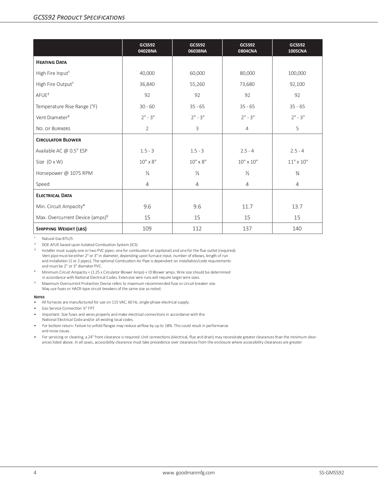
GCSS920402BNAA
GCSS920603BNA
GCSS920603BNAA
GCSS920804CNAA
GCSS921005CNAA
GCSS96
GCSS960402BNA
GCSS960402BNAA
GCSS960603BNAA
GCSS960804CNAA
GCSS961005CNAA
GCSS961205DNAA
GCVC8
GCVC80603BXBC
GCVC80803BXBC
GCVC80805CXBC
GCVC81005CXBC
GCVC950714CXBA
GCVC950915DXBA
GCVC960403BNA
GCVM970603BNA
GDH8
GDH80403AB
GDH80403ANAA
GDH80403ANBA
GDH80403ANBB
GDH80403AXAA
GDH80403AXBA
GDH80403AXBB
GDH80603ANAA
GDH80603ANBA
GDH80603ANBB
GDH80603AXAA
GDH80603AXBA
GDH80603AXBB
GDH80804BNAA
GDH80804BNBA
GDH80804BNBB
GDH80804BXAA
GDH80804BXBA
GDH80804BXBB
GDH81005CNAA
GDH81005CNBA
GDH81005CNBB
GDH81005CXAA
GDH81005CXBA
GDH81005CXBB
GDS8
2
GDS80403ANB
GDS80453ANAA
GDS80453AXAA
Loading...
Loading...
Nothing found
GCSS920603BNA
User Manual
12 pgs
600.61 Kb
0
Table of contents
Loading...
Goodman GCSS920603BNA User Manual
...
Goodman User Manual
Download
Specifications and Main Features
Frequently Asked Questions
User Manual
Download
Loading...
+
8
hidden pages
Unhide
You need points to download manuals.
1 point = 1 manual.
You can buy points or you can get point for every manual you upload.
Buy points
Upload your manuals
 Loading...