

Page 1
EFR01
EXTERNAL FIL TER RACK KIT
INSTALLATION INSTRUCTIONS
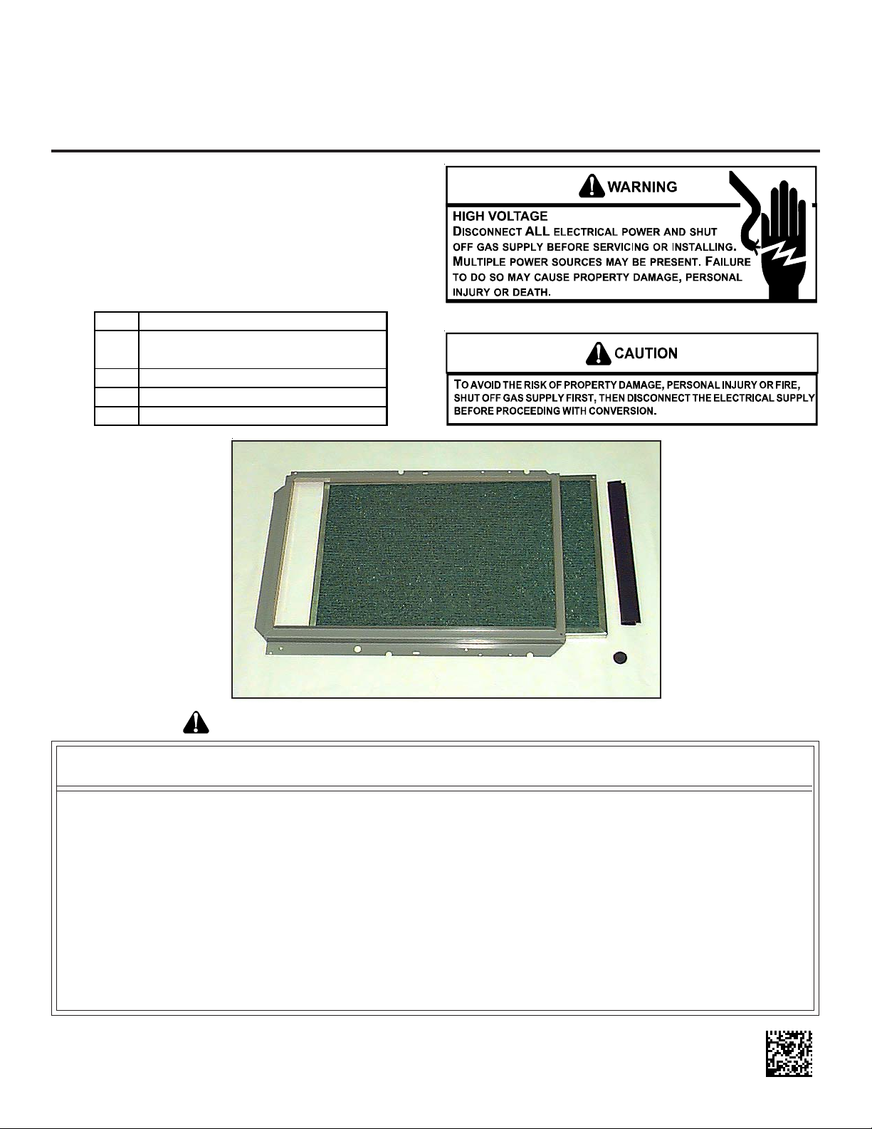
Description
This external filter rack kit is intended to provide a location,
external to the furnace casing, for installation of a permanent
filter. The rack is designed to mount over the indoor air blower
compartment area of either side panel, and provide filter retention as well as a location for attaching return air ductwork.
Kit Contents
1 Sheet Metal Rack Assembly
16" x 25" x 1" Permanent (Washable)
1
High -Velocity Filter
1 Plastic Filter Clip
1Plastic Plug
Installation Instructions
Goodman Manufacturing Company, L.P. © 1997-2007
5151 San Felipe, Suite 500, Houston, TX 77056
www.goodmanmfg.com -or- www.amana-hac.com
P/N: IO-688 Date: August 2007
RECOGNIZE THIS SYMBOL AS A SAFETY PRECAUTION
ATTENTION INSTALLING PERSONNEL
As a professional installer, you have an obligation to know the product better than the customer.
This includes all safety precautions and related items.
Prior to actual installation, thoroughly familiarize yourself with this Instruction Manual.
Pay special attention to all safety warnings. Often during installation or repair,
it is possible to place yourself in a position which is more hazardous than when the unit is in operation.
Remember, it is your responsibility to install the product safely and to know it well enough
to be able to instruct a customer in its safe use.
Safety is a matter of common sense... a matter of thinking before acting.
Most dealers have a list of specific, good safety practices... follow them.
The precautions listed in this Installation Manual are intended as supplemental to existing practices.
However, if there is a direct conflict between existing practices and the content of this manual,
the precautions listed here take precedence.
Page 2

CONTENTS
Important Information.......................................................... 2
Location & Placement........................................................ 2
Number of Kits Required .................................................... 2
Less than 5 Tons of Airflow.......................................... 2
Five T ons of Airflow...................................................... 2
Installation Precautions and Considerations ....................... 3
Disconnect Electrical Power ....................................... 3
Furnace Airflow Requirements ..................................... 3
Drain Trap Relocation.................................................. 3
Electrical Connection Compatibility on
90 % Efficient Furnaces ....................................... 3
Mating Ductwork Dimension........................................ 3
Filter Access and Removal.......................................... 3
Installation Procedure......................................................... 3
Filter Care................................................................... 4
Filter Replacement...................................................... 4
IMPORTANT INFORMA TION
Contact a local propane gas supplier
about installing a gas detecting warning device.
NOTE: To ensure proper operation, inst all, operate and main-
tain the unit in accordance with these installation instructions,
all local building codes and ordinances. In their absence,
follow the latest edition of the National Fuel Gas Code (NFP A
54/ANSI Z223.1), and/or CAN/CSA B149.1 Installation Codes.
LOCA TION & PLACEMENT
This kit is designed for side panel application to Upflow furnace
models. Note that furnace condensate drain trap relocation is
required on 90% efficient furnace installations supporting five
tons of airflow through two side return air ductwork connections. Refer to Installation Precautions and Considerations
section for details.
NOTE: Condensate drain trap must be relocated on five ton
airflow 90% units (two side return air ductwork connections).
NUMBER OF KITS REQUIRED
Less Than Five Tons of Airflow
Installations supporting less than five tons of airflow require
only one return air ductwork connection when a permanent
filter is used. For this case one filter rack kit is required.
NOTE: This filter rack cannot be applied to a bottom return.
On 90% furnaces, the drain trap must be located either opposite the side receiving the filter rack or relocated (see Drain
Trap Relocation section).
Five Tons of Airflow
Installations supporting five tons of airflow require two return air
ductwork connections. If both connections are side panel connections, two filter rack kits are required. When a bottom
return is used in conjunction with a side panel connection, a
permanent filter must be installed in the bottom return and a
filter rack kit used for the side panel connection.
NOTE: This filter rack cannot be applied to a bottom return.
On 90% furnaces, the drain trap must be located either opposite the side receiving the filter rack or relocated (see Drain
Trap Relocation section).
2
Page 3

INSTALLA TION PRECAUTIONS AND CONSIDERATIONS
Mating Ductwork Dimensions
Refer to the following figure for filter rack dimensions.
23.567
Disconnect Electrical Power
Turn OFF electrical power to furnace prior to installation of the
filter kit. Use caution when installing screws into furnace cabinet as to prevent damage to internal furnace components.
Furnace Airflow Requirements
Use adequate return air ductwork connections to accommodate an installation’s airflow tonnage requirements. Refer to
furnace Installation Instructions or Specifications Sheet for details.
Drain Trap Relocation
Furnace drain trap relocation will be required on 90% furnace
installations if the filter rack kit is to be installed on the same
side as the furnace’s condensate drain trap, or if the installation supports five tons of airflow (two side return air ductwork
connections). Drain lines may be extended to clear the filter
rack, and the trap mounted to the ductwork. Drain lines must
maintain a downward slope to the drain trap.
Electrical Connection Compatibility on 90% Efficient
Furnaces
Use of an alternate electrical inlet is required on 90% furnace
installations if the kit is to be applied on the same side as the
furnace’s junction box, or if the installation supports five tons of
airflow (two side return air ductwork connections). The alternate inlet will allow electrical connections through the blower
compartment to the junction box without interfering with the
filter removal (Figure 1).
14.500
Figure 2
Filter Dimensions
Filter Access and Removal
The installed position of the furnace should be taken into account when determining which side(s) will receive the filter rack.
Assure that the filter(s) may be removed for cleaning purposes
once the furnace, ductwork, and electrical and drainage connections are in place.
INST ALLATION PROCEDURE
1. Turn OFF power to furnace.
2. Select side(s) to receive filter rack.
Figure 1
Alternate Electrical Inlet Location
90% Furnaces Only
3. Using the corner marks provided on the side panel(s) as
guidelines, mark an outline and cut out the return air cutout area(s) (Figure 3).
4. On 80% efficient furnace models, remove the two screws
securing the side panel internal filter retainers and the
retainers themselves.
5. An alternate electrical inlet must be provided on 90% furnace installations in which the electrical supply connection and junction box are on the same side as a filter
rack. Place an 0.875” diameter hole in the side panel
supporting the electrical connection at the location shown
in Figure 1. Attach electrical inlet to this location and
plug standard electrical inlet with plug provided.
6. Remove and save two screws from blower deck and one
screw from lower edge of the furnace. The filter rack should
be positioned against the side panel to locate the screws
requiring removal. When properly located, the filter rack
will be flush with the back panel and bottom edge of the
furnace.
3
Page 4

INTERNAL FILTER
RETAINER SCREWS
(80% MODELS ONLY)
SLOTS IN FILTER
CLEAR SCREWS
ON UNIT
BLOWER DECK
SCREWS
Dirty filters are the most common cause of inadequate heating
and cooling performance. Filters should be inspected and
cleaned every two months or as required. The permanent filter
supplied with the kit should be cleaned as follows:
UNIT
SIDE
PANEL
FRONT
OF UNIT
FILTER RACK
ASSEMBLY
CUTOUT ARE A
FILTER KIT PLUG FOR
STANDARD ELECTRICAL INLET
RETURN AIR
LOWER EDGE
SCREW
(FACE FILTER
OPENING
TOWARDS FRONT
OF UNIT)
Figure 3
Return Air Cutout
7. Attach sheet metal filter rack(s) using screws removed in
prior step. Additional installer-supplied, self-drilling screws
may be added if desired.
8. Attach ductwork to filter rack(s).
Note: On 90% efficient furnaces, make appropriate drain trap
and drain hose connections.
9. If not already attached, clip filter clip(s) to 16-inch side of
filter(s).
10. Insert filter(s) with clip into the front opening of filter rack(s).
Verify that filter(s) is (are) fully inserted, seated properly,
and can be easily removed by grasping the filter clip.
Filter(s) should slide in easily, do not force.
11. Turn ON power to furnace.
12. Verify proper furnace operation as outlined in the furnace’s
Installation Manual.
FIL TERS
Filter Care
Note: Disposable filters must not be used with the filter rack
from this kit. A permanent-type, washable filter designed for
high velocity airflow applications is supplied with this kit. Usage
of a permanent filer is required due to the higher airflow velocities
associated with the large airflow volume (CFM) moving through
the available filter cross sectional surface area.
1. Turn OFF power to the furnace.
2. Remove filter(s) through front of the rack(s) by gently pulling on the plastic filter clip. Filter(s) should slide out
easily, do not force.
3. Wash filter(s) with low pressure, clean water. Water should
be applied from opposite the direction of airflow to avoid
driving dirt into the filter.
4. Allow filter(s) to air dry. Drain holes are provided in the
metal frame.
5. Reinstall filter(s) through front of the rack(s). Verify that
filter(s) is (are) fully inserted, seated properly, and can be
easily removed by grasping the filter clip. Filter(s) should
slide in easily, do not force.
If the original filter(s) supplied with the kit have been replaced,
follow the new filter manufacturer’s recommendations for step
3 and 4 of the cleaning process.
Filter Replacement
Should it become necessary to replace a filter, it must be replaced with a permanent-type filter of the same size as supplied and suitable for face velocities of 600 feet/minute. Follow
filter manufacturer’s care recommendations.
To remove plastic clip from filter:
1. Slide clip towards one corner of the frame.
2. Spread clip slightly to clear frame at corner.
3. Continue to slide clip until it is free of filter.
NOTE: SPECIFICATIONS AND PERFORMANCE DATA LISTED HEREIN ARE SUBJECT TO CHANGE WITHOUT NOTICE
Quality Makes the Difference!
All of our systems are designed and manufactured with the same high quality standards regardless of size or efficiency. We have designed these units to significantly reduce the most frequent causes of product failure. They are
simple to service and forgiving to operate. We use quality materials and components. Finally, every unit is run tested
before it leaves the factory. That’ s why we know. . .There’s No Better Quality.
Visit our website at www.goodmanmfg.com or www.amana-hac.com for information on:
• Products
• Warranties
© 1997 - 2007 Goodman Manufacturing Company, L.P.
• Customer Services
• Parts
4
• Contractor Program and Training
• Financing Options
 Loading...