

Page 1
I
NST ALLATION
I
NSTRUCTIONS
FOR
*(D, M)VC8 G
AS
F
URNACE
(CA TEGORY I )
Installer: Affix all manuals adjacent to the unit.
These furnaces comply with requirements embodied in the American National S tandard / National Standard of Canada ANSI Z21.47·CSA-
2.3 Gas Fired Central Furnaces.
RECOGNIZE THIS SYMBOL AS A SAFETY PRECAUTION.
ATTENTION INSTALLING PERSONNEL
As a professional installer , you have an obligation to know the product better than the customer .
This includes all safety precautions and related items.
Prior to actual installation, thoroughly familiarize yourself with this Instruction Manual.
Pay special attention to all safety warnings. Often during installation or repair , it is possible to place yourself
in a position which is more hazardous than when the unit is in operation.
Remember, it is your responsibility to inst all the product safely and to know it well enough
to be able to instruct a customer in its safe use.
Safety is a matter of common sense...a matter of thinking before acting.
Most dealers have a list of specific, good safety practices...follow them.
The precautions listed in this Installation Manual are intended as supplemental to existing practices.
However, if there is a direct conflict between existing practices and the content of this manual,
the precautions listed here take precedence.
NOTE: Please contact your distributor or our website listed below
for the applicable Specification Sheet referred to in this manual.
WARN ING
G
OODMANWILLNOTBERESPO NSIBLEFORANYINJURYORPROPERTY
DAMAGEARISINGFROMIMPROPERSERVICEORSERVICEPROCEDURES
FYOUINSTALLORPERFORMSERVICEONTHISUNIT,YOUASSUME
I
RESPO NSIBILITYFORANYPERSONALINJURYORPROPERTYDAMAGE
WHICHMAYRESULT
INSTALLORSERVICEHEATINGANDAIRCONDITIONINGEQUIPMENT
.M
ANYJURISDICTIONSREQUIREALICENSETO
.
.
IO-429A
6/2013
is a registered trademark of Maytag Corporation or its related companies and is used under license. All rights reserved.
5151 San Felipe Suite 500 • Houston, TX 77056
www.goodmanmfg.com • www .amana-hac.com
© 2011 - 2013 Goodman Manufacturing Company, L.P.
Page 2

Table of Contents
SAFETY CONSIDERATIONS ........................................................................................................................................................... 4
A
DDITIONAL SAFETY CONSIDERATIONS ................................................................................................................................... 5
SHIPPING INSPECTION ........................................................................................................................................................ 5
ELECTROSTATIC DISCHARGE (ESD) PRECAUTIONS ................................................................................................................... 6
TO THE INSTALLER............................................................................................................................................................ 6
PRODUCT DESCRIPTION ............................................................................................................................................................. 6
FEATURES ........................................................................................................................................................................ 6
RODUCT APPLICATION .............................................................................................................................................................. 6
P
LOCATION REQUIREMENTS AND CONSIDERATIONS ............................................................................................................................. 7
CLEARANCES AND ACCESSIBILITY ......................................................................................................................................... 9
INSTALLATION POSITIONS ..................................................................................................................................................... 9
HORIZONT AL INSTALLATION (*MVC8 MODELS ONLY) ............................................................................................................... 9
FURNACE SUSPENSION ...................................................................................................................................................... 9
EXISTING FURNACE REMOVAL .............................................................................................................................................. 9
THERMOST AT LOCATION ....................................................................................................................................................... 9
COMBUSTION AND VENTILATION AIR REQUIREMENTS ...................................................................................................................... 10
EXTERIOR MASONRY CHIMNEYS .................................................................................................................................................. 11
(CA TEGORY I FURNACES ONLY).................................................................................................................................................. 11
C
HECKLIST SUMMARY ...................................................................................................................................................... 12
CHECK 1 - PROPER CHIMNEY TERMINATION. ........................................................................................................................ 12
CHECK 2 - ANY SOLID OR LIQUID FUEL APPLIANCES VENTED INTO THIS CHIMNEY CHANNEL ....................................................... 13
CHECK 3 - CHIMNEY CROWN CONDITION. ........................................................................................................................... 13
CHECK 4 - DEBRIS IN CLEANOUT....................................................................................................................................... 13
CHECK 5 - LINER CONDITION. .......................................................................................................................................... 13
CHECK 6 - DILUTION AIR. ............................................................................................................................................... 14
CHECK 7 - COMPLETE THE INSTALLATION. ............................................................................................................................ 14
FIX 1 - LINER TERMINATION .............................................................................................................................................. 14
FIX 2 -CHANGE VENTING ARRANGEMENTS ........................................................................................................................... 14
FIX 3 - REBUILD THE CROWN ........................................................................................................................................... 15
FIX 4 - RELINING............................................................................................................................................................ 15
ELECTRICAL CONNECTIONS ....................................................................................................................................................... 15
WIRING HARNESS ........................................................................................................................................................... 16
115 VOLT LINE CONNECTIONS .......................................................................................................................................... 16
JUNCTION BOX RELOCATION ............................................................................................................................................. 16
24 VOLT THERMOSTAT WIRING .......................................................................................................................................... 17
SINGLE-STAGE HEATING THERMOSTAT APPLICATION ................................................................................................................ 17
24 VOLT DEHUMIDISTAT WIRING ........................................................................................................................................ 18
FOSSIL FUEL APPLICATIONS.............................................................................................................................................. 18
115 VOLT LINE CONNECTION OF ACCESSORIES (HUMIDIFIER AND ELECTRONIC AIR CLEANER).................................................... 18
24 VOLT HUMIDIFIER....................................................................................................................................................... 19
AUXILIARY ALARM SWITCH ............................................................................................................................................... 19
GAS SUPPL Y AND PIPING.......................................................................................................................................................... 19
HIGH ALTITUDE DERATE ................................................................................................................................................... 20
PROPA N E GAS CONVERSION .............................................................................................................................................. 20
GAS PIPING CONNECTIONS ............................................................................................................................................... 20
UPFLOW INSTALLATIONS .................................................................................................................................................... 21
COUNTERFLOW INSTALLA TIONS ........................................................................................................................................... 21
GAS PIPING CHECKS ....................................................................................................................................................... 22
PROPANE GAS TANKS AND PIPING ...................................................................................................................................... 22
CIRCULATING AIR AND FILTERS .................................................................................................................................................. 23
CHECKING DUCT STATIC ................................................................................................................................................... 23
FILTERS - READ THIS SECTION BEFORE INSTALLING THE RETURN AIR DUCTWORK .................................................................... 24
UPRIGHT INSTALLA TIONS ................................................................................................................................................... 24
CIRCULATION AIR FILTERS ................................................................................................................................................ 24
HORIZONT A L INSTALLATIONS ............................................................................................................................................... 24
2
Page 3

Table of Contents
START-UP PROCEDURE AND ADJUSTMENT ................................................................................................................................... 24
HEAT ANTICIPATOR SETTING ............................................................................................................................................... 24
FURNACE OPERATION ....................................................................................................................................................... 24
GAS SUPPLY PRESSURE MEASUREMENT .............................................................................................................................. 25
GAS MANIFOLD PRESSURE MEASUREMENT AND ADJUSTMENT .................................................................................................. 26
GAS INPUT RATE MEASUREMENT (NA TURAL GAS ONLY)........................................................................................................... 27
TEMPERATURE RISE ......................................................................................................................................................... 27
CIRCULATOR BLOWER SPEEDS .......................................................................................................................................... 28
BLOWER HEAT OFF DELAY TIMINGS .................................................................................................................................... 30
COMFORTNET™ SYSTEM .......................................................................................................................................................... 30
OVERVIEW ..................................................................................................................................................................... 30
FOSSIL FUEL APPLICATIONS.............................................................................................................................................. 31
CTK0* WIRING ............................................................................................................................................................. 31
COMFORTNET™ COMPATIBLE FURNACE WITH NON-COMFORTNET COMPATIBLE SINGLE-STAGE AIR CONDITIONER .............................. 32
COMFORTNET™ SYSTEM ADVANCED FEATURES............................................................................................................................. 32
THERMOSTAT MENU ......................................................................................................................................................... 32
DIAGNOSTICS .................................................................................................................................................................. 32
FURNACE ADVANCED FEATURES MENUS (ACCESSED THROUGH COMMUNICATING THERMOST AT)..................................................... 33
NETWORK TROUBLESHOOTING ........................................................................................................................................... 34
S
YSTEM TROUBLESHOOTING .............................................................................................................................................. 34
NORMAL SEQUENCE OF OPERATION ............................................................................................................................................ 34
POWER UP .................................................................................................................................................................... 34
HEATING MODE ............................................................................................................................................................... 35
COOLING MODE ............................................................................................................................................................. 36
FAN ONLY MODE ............................................................................................................................................................ 36
OPERATIONAL CHECKS ............................................................................................................................................................. 36
SAFETY CIRCUIT DESCRIPTION ................................................................................................................................................... 37
INTEGRATED CONTROL MODULE ......................................................................................................................................... 37
PRIMARY LIMIT................................................................................................................................................................ 37
AUXILIARY LIMIT ............................................................................................................................................................. 37
ROLLOUT LIMIT .............................................................................................................................................................. 37
PRESSURE SWITCHES...................................................................................................................................................... 37
FLAME SENSOR .............................................................................................................................................................. 37
TROUBLESHOOTING ................................................................................................................................................................. 37
ELECTROSTATIC DISCHARGE (ESD) PRECAUTIONS ................................................................................................................. 37
DIAGNOSTIC CHART ......................................................................................................................................................... 37
FAULT RECALL ................................................................................................................................................................ 37
RESETTING FROM LOCKOUT .............................................................................................................................................. 38
MAINTENANCE ......................................................................................................................................................................... 38
ANNUAL INSPECTION ........................................................................................................................................................ 38
FILTERS ........................................................................................................................................................................ 38
BURNERS ...................................................................................................................................................................... 38
INDUCED DRAFT AND CIRCULATOR BLOWERS ....................................................................................................................... 39
FLAME SENSOR (QUALIFIED SERVICER ONLY)...................................................................................................................... 39
FLUE PASSAGES (QUALIFIED SERVICER ONLY)..................................................................................................................... 39
BEFORE LEAVING AN INSTALLA TION.............................................................................................................................................. 39
REPAIR AND REPLACEMENT PARTS .............................................................................................................................................. 39
TROUBLESHOOTING CHART ....................................................................................................................................................... 40
ST ATUS CODES ....................................................................................................................................................................... 45
AIR FLOW DATA ...................................................................................................................................................................... 46
DIP SWITCHES ....................................................................................................................................................................... 47
*MVC8, *DVC8 WIRING DIAGRAM ........................................................................................................................................... 48
3
Page 4
S
AFETY
C
ONSIDERA TIONS
WARNING
Adhere to the following warnings and cautions when installing,
adjusting, altering, servicing, or operating the furnace. T o ensure proper installation and operation, thoroughly read this
manual for specifics pertaining to the installation and application of this product.
This furnace is manufactured for use with natural gas. It may
be field converted to operate on L.P . gas by using the appropriate L.P . conversion kit listed in the PROPANE GAS/HIGH AL-
TITUDE INST ALLATIONS section of this manual
Install this furnace only in a location and position as specified
in LOCATION REQUIREMENTS & CONSIDERA TIONS sec-
tion and INST ALLATION POSITIONS section of this manual.
Provide adequate combustion and ventilation air to the furnace
as specified in COMBUSTION & VENTILATION AIR RE-
QUIREMENTS section of this manual.
Combustion products must be discharged to the outdoors.
Connect this furnace to an approved vent system only , as specified in VENT/FLUE PIPE & COMBUSTION AIR PIPE section
of this manual.
Never test for gas leaks with an open flame. Use a commercially available soap solution made specifically for the detection of leaks to check all connections, as specified in GAS
SUPPLY AND PIPING section of this manual.
Always install a furnace to operate within the furnace’s intended
temperature-rise range with a duct system which has external
static pressure within the allowable range, as specified on the
furnace rating plate and OPERA TIONAL CHECKS section of
these instructions.
When a furnace is installed so that supply ducts carry air circulated by the furnace to areas outside the space containing
the furnace, the return air shall also be handled by duct(s)
sealed to the furnace casing and terminating outside the space
containing the furnace.
A gas-fired furnace for installation in a residential garage must
be installed as specified in the LOCATION REQUIREMENTS
AND CONSIDERA TIONS section of this manual.
This furnace may be used as a construction site heater only if
certain conditions are met. These conditions are listed in the
PRODUCT APPLICATION section of this manual.
IF
THEINFORMATIONINTHESEINSTRUCTIONSISNOTFOLLOWED
EXACTLY,AFIREOREXPLOSIONMAYRESULTCAUSINGPROPERTY
DAMAGE
,
PERSONALINJURYORLOSSOFLIFE
DO
NOTSTOREORUSEGASO LINEOROTHERFLAMMABLEVAPORSAND
LIQUIDSINTHEVICINITYOFTHISORANYOTHERAPPLIANCE
.
.
WHATTODOIFYOUSMELLGAS:
D
ONOTTRYTOLIGHTANYAPPLIANCE
D
ONOTTOUCHANYELECTRICALSWITCH;DONOTUSEANYPHONE
INYOURBUILDING
I
MMEDIATELYCALLYOURGASSUPPLIERFROMANEIGHBOR’S
PHONE
.F
I
FYOUCANNOTREACHYOURGASSUPPLIER,CALLTHEFIRE
DEPARTMENT
I
NSTALLATIONANDSERVICEMUSTBEPERFORMEDBYAQUALIFIED
INSTALLER,SERVICEAGENCYORTHEGASSUPPLIER
.
OLLOWTHEGASSUPPLIER’SINSTRUCTIONS
.
.
.
.
WARNING
T
HISPRODUCTCONTAINSORPRODUCESACHEMICALORCHEMICALS
WHICHMAYCAUSESERIOUSILLNESSORDEATHANDWHICHARE
KNOWNTOTHESTATEOFCALIFORNIATOCAUSECANCER,BIRTH
DEFECTSOROTHERREPRODUCTIVEHARM
.
WARNING
H
EATINGUNITSHOULDNOTBEUTILIZEDWITHOUTREASONABLE
ROUTINE,INSPECTION,MAINTENANCEANDSUPERVISION
BUILDINGINWHICHANYSUCHDEVICEISLOCATEDWILLBEVACANT
CARESHOULDBETAKENTHATSUCHDEVICEISROUTINELYINSPECTED
MAINTAINEDANDMONITORED.INTHEEVENTTHATTHEBUILDING
MAYBEEXPOSEDTOFREEZINGTEMPERATURESANDWILLBEVACANT
ALLWATER‐BEARINGPIPESSHOULDBEDRAINED,THEBUILDINGSHOULD
BEPROPERLYWINTERIZED,ANDTHEWATERSOURCECLOSED.INTHE
EVENTTHATTHEBUILDINGMAYBEEXPOSEDTOFREEZING
TEMPERATURESANDWILLBEVACANT,ANYHYDRONICCOILUNITS
SHOULDBEDRAINEDASWELLAND,INSUCHCASE,ALTERNATIVEHEAT
SOURCESSHOULDBEUTILIZED
.
.IF
THE
,
,
,
,
WARNING
TO
PREVENTPOSSIBLEPROPERTYDAMAGE,PERSONALINJURYOR
DEATHDUETOELECTRICALSHOCK,THEFURNACEMUSTBELOCATEDTO
PROTECTTHEELECTRICALCOMPONENTSFROMWATER
.
WARNING
TO
PREVENTPERSONALINJURYORDEATHDUETOIMPROPER
INSTALLATION,ADJUSTMENT,ALTERATION,SERVICEORMAINTENANCE
REFERTOTHISMANUAL
INFORMATION,CONSULTAQUALIFIEDINSTALLER,SERVICERAGENCYOR
THEGASSUPPLIER
.FOR
ADDITIONALASSISTANCEOR
.
,
4
Page 5
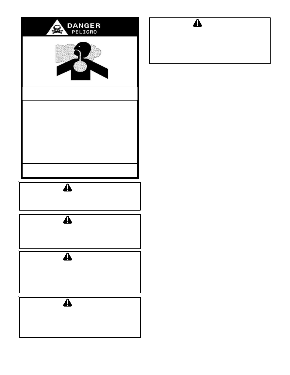
CARBON MONOX IDE POI SONING HAZARD
Spec ial Warning f o r In s ta llation of F ur nace or Air Han dl i n g Units in
Enclosed Areas such as Garages, Utility Rooms or Parking Areas
Carbon monoxide producing de vices (such as an automobile, spa ce
heater, g as water heater, etc.) sh ould not be op erated in enclosed areas
such as unventi lated gara ges, utility rooms or parking areas because of
the danger of carbon monoxide (CO) poisoning resulting from the exhaust
emissio ns. If a furnace or air handler is installed in an enclosed area such
as a garage, utility room or parking area and a carbon monoxide producing
device is operated therein, there must be adeq uate, direct outside
ventilation.
This ventilation is necessary to avoid the danger of CO poisoning which
can occur if a carbon monoxide producing device continues to operate in
the enclosed area. Car bon monoxide emissio ns can be (re)c irculated
through out the stru cture if the furnace or air handler is operating in any
mode.
CO can cause serious illness including permanent brain damage or death.
-
B10259-216
WARN ING
S
HOULDOVERHEATINGOCCURORTHEGASSUPPLYFAILTOSHUTOFF
TURNOFFTHEMANUALGASSHUTOFFVALVEEXTERNALTOTHE
FURNACEBEFORETURNINGOFFTHEELECTRICALSUPPLY
.
WARN ING
P
OSSIBLEPROPERTYDAMAGE,PERSONALINJURYORDEATHDUETO
FIRE,EXPLOSION,SMOKE,SOOT,CONDENSATION,ELECTRICALSHOCK
ORCARBO NMONOXIDEMAYRESULTFROMIMPROPERINSTALLATION
REPAIROPERATION,ORMAINTENANCEOFTHISPRODUCT
.
WARNING
TO
PREVENTPERSONALINJURYORDEATHDUETOASPHYXIATION,THIS
FURNACEMUSTBECATEGORY
ATEGORY
C
ROVISIONSMUSTBEMADEFORVENTINGCOMBUSTIONPRODUCTS
P
OUTDOORSTHROUGHAPROPERVENTINGSYSTEM
FLUEPIPECOULDBEALIMITINGFACTORINLOCATINGTHEFURNACE
III
VENTING
I
VENTED
.DO
NOTVENTUSING
.
.THE
LENGTHOF
.
ADDITIONAL SAFETY CONSIDERATIONS
• This furnace is approved for Category I Venting only .
• Provisions must be made for venting combustion
products outdoors through a proper venting system.
The length of flue pipe could be a limiting factor in
locating the furnace.
SHIPPING INSPECTION
All units are securely packed in shipping containers tested
according to International Safe Transit Association specifications. The carton must be checked upon arrival for external
damage. If damage is found, a request for inspection by carrier’s
agent must be made in writing immediately .
The furnace must be carefully inspected on arrival for damage
and bolts or screws which may have come loose in transit. In
the event of damage the consignee should:
1. Make a notation on delivery receipt of any visible damage
to shipment or container.
2. Notify carrier promptly and request an inspection.
3. With concealed damage, carrier must be notified as soon
,
,
as possible - preferably within five days.
4. File the claim with the following support documents within
a nine month statute of limitations.
• Original or certified copy of the Bill of Lading, or
indemnity bond.
• Original paid freight bill or indemnity in lieu thereof.
• Original or certified copy of the invoice, showing trade
and other discounts or reductions.
• Copy of the inspection report issued by carrier’s
representative at the time damage is reported to carrier .
WARN ING
TO
PREVENTPERSONALINJURYORDEATHDUETOIMPROPER
INSTALLATION,ADJUSTMENT,ALTERATION,SERVICEORMAINTENANCE
REFERTOTHISMANUAL
INFORMATION,CONSULTAQUALIFIEDINSTALLER,SERVICERAGENCYOR
THEGASSUPPLIER
.FOR
ADDITIONALASSISTANCEOR
.
WARN ING
T
HISUNITMUSTNOTBEUSEDASA“CONSTRUCTIONHEATER”DURING
THEFINISHINGPHASESOFCONSTRUCTIONONANEWSTRUCTURE
TYPEOFUSEMAYRESULTINPREMATUREFAILUREOFTHEUNITDUETO
EXTREMELYLOWRETURNAIRTEMPERATURESANDEXPOSURETO
CORROSIVEORVERYDIRTYATMOSPHERES
.
The carrier is responsible for making prompt inspection of dam-
age and for a thorough investigation of each claim. The distributor or manufacturer will not accept claims from dealers for trans-
,
portation damage.
Keep this literature in a safe place for future reference.
.T
HIS
5
Page 6
ELECTROSTATIC DISCHARGE (ESD) PRECAUTIONS
NOTE: Discharge body’s static electricity before touching unit.
An electrostatic discharge can adversely affect electrical components.
Use the following precautions during furnace installation and
servicing to protect the integrated control module from damage. By putting the furnace, the control, and the person at the
same electrostatic potential, these steps will help avoid exposing the integrated control module to electrostatic discharge.
This procedure is applicable to both installed and non-installed
(ungrounded) furnaces.
1. Disconnect all power to the furnace. Do not touch the
integrated control module or any wire connected to the
control prior to discharging your body’s electrostatic
charge to ground.
2. Firmly touch a clean, unpainted, metal surface of the
furnaces near the control. Any tools held in a person’ s
hand during grounding will be discharged.
3. Service integrated control module or connecting wiring
following the discharge process in step 2. Use caution
not to recharge your body with static electricity; (i.e., do
not move or shuffle your feet, do not touch ungrounded
objects, etc.). If you come in contact with an ungrounded
object, repeat step 2 before touching control or wires.
4. Discharge your body to ground before removing a new
control from its container. Follow steps 1 through 3 if
installing the control on a furnace. Return any old or
new controls to their containers before touching any
ungrounded object.
TO THE INSTALLER
Before installing this unit, please read this manual thoroughly
to familiarize yourself with specific items which must be adhered to, including but not limited to: unit maximum external
static pressure, gas pressures, BTU input rating, proper electrical connections, circulating air temperature rise, minimum or
maximum CFM, and motor speed connections, and venting.
These furnaces are designed for Category I venting only .
WARNING
TO
PREVENTPROPERTYDAMAGE,PERSONALINJURYORDEATHDUETO
FIRE,DONOTINSTALLTHISFURNACEINAMOBILEHOME,TRAILER,OR
RECREATIONALVEHICLE
P
RODUCT DESCRIPTION
.
FEATURES
This furnace is a part of the ComfortNet™ family of products.
The CTK0* ComfortNet thermostat kit allows this furnace to be
installed as part of a digitally communicating system. The
ComfortNet system provides automatic airflow configuration,
enhanced setup features, and enhanced diagnostics. It also
reduces the number of thermostat wires to a maximum of four.
It may be also installed as part of a “legacy” system using a
standard 24 V AC thermostat.
This product may also be installed with the ComfortNet thermostat and a non-ComfortNet compatible single stage air conditioning unit. However, this reduces the benefits of the
ComfortNet system as the enhancements will only apply to the
furnace.
P
RODUCT APPLICA TION
This furnace is primarily designed for residential home-heating
applications. It is NOT designed or certified for use in mobile
homes, trailers or recreational vehicles. Neither is it designed
or certified for outdoor applications. The furnace must be installed indoors (i.e., attic space, crawl space, or garage area
provided the garage area is enclosed with an operating door).
This furnace can be used in the following non-industrial commercial applications:
Schools, Office buildings, Churches, Retail stores,
Nursing homes, Hotels/motels, Common or office areas
In such applications , the furnace must be installed with the
following stipulations:
• It must be installed per the installation instructions
provided and per local and national codes.
• It must be installed indoors in a building constructed
on site.
• It must be part of a ducted system and not used in a
free air delivery application.
• It must not be used as a “make-up” air unit.
• All other warranty exclusions and restrictions apply.
This furnace may be used as a construction site heater ONLY
if the following conditions are met:
• The vent system is permanently installed per these
installation instructions.
• A room thermostat is used to control the furnace. Fixed
jumpers that provide continuous heating CANNOT be
used.
• Return air ducts are provided and sealed to the furnace.
• A return air temperature range between 60ºF (16ºC)
and 80ºF (27ºC) is maintained.
• Air filters are installed in the system and maintained
during construction, replaced as appropriate during
construction, and upon completion of construction are
replaced.
• The input rate and temperature rise are set per the
furnace rating plate.
• 100% outside air is provided for combustion air
requirements during construction. T emporary ducting
can be used.
NOTE: Do not connect the temporary duct directly to
the furnace. The duct must be sized for adequate
combustion and ventilation in accordance with the
latest edition of the National Fuel Gas Code NFP A 54/
ANSI Z223.1 orCAN/CSA B149.1 Installation Codes.
6
Page 7
• The furnace heat exchanger, components, duct
system, air filters and evaporator coils are thoroughly
cleaned following final construction clean up.
• All furnace operating conditions (including ignition, input
rate, temperature rise and venting) are verified
according to these installation instructions.
NOTE: The Commonwealth of Massachusetts requires that the
following additional requirements must also be met:
• Gas furnaces must be installed by a licensed plumber
or gas fitter.
• A T -handle gas cock must be used.
• If the unit is to be installed in an attic, the passageway
to and the service area around the unit must have
flooring.
WARN ING
TO
PREVENTPROPERTYDAMAGE,PERSONALINJURYORDEATHDUETO
FIRE,DONOTINSTALLTHISFURNACEINAMOBILEHOME,TRAILER,OR
RECREATIONALVEHICLE
.
In the USA, this furnace MUST be installed in accordance with
the latest edition of the ANSI Z223.1 booklet entitled “National
Fuel Gas Code” (NFPA 54), and the requirement s or codes of
the local utility or other authority having jurisdiction. In Canada,
this furnace must be installed in accordance with the current
CAN/CGA-B149.1 & 2 Gas Installation Codes, local plumbing
or waste water codes and other applicable codes. Additional
helpful publications available from the NFP A are, NFPA 90A Installation of Air Conditioning and V entilating System and NFP A
90B - Warm Air Heating and Air Conditioning System.
All venting shall be in accordance with PAR T 7, V enting of Equipment, of the National Fuel Gas Code, ANSI Z223.1, or applicable local building and/or air conditioning codes. These publications are available from:
National Fire Protection Association, Inc.
1 Batterymarch Park, Quincy , MA 02269
NOTE: Furnaces with NOx screens meet the California NOx
emission standards and California seasonal efficiency standards. ANNUAL inspections of the furnace and its vent system
is strongly recommended.
To ensure proper furnace operation, install, operate and
maintain the furnace in accordance with these installation and operation instructions, all local building codes
and ordinances. In their absence, follow the latest edition of
the National Fuel Gas Code (NFP A 54/ANSI Z223.1), and/or
CAN/CSA B149 Installation Codes, local plumbing or waste
water codes, and other applicable codes.
A copy of the National Fuel Gas Code (NFP A 54/ANSI Z223.1)
can be obtained from any of the following:
American National Standards Institute
1430 Broadway
New York, NY 10018
National Fire Protection Association
1 Batterymarch Park
Quincy , MA 02269
CSA International
8501 East Pleasant V alley
Cleveland, OH 44131
A copy of the CAN/CSA B149 Installation Codes can also be
obtained from:
CSA International
178 Rexdale Boulevard
Etobicoke, Ontario, Canada M9W 1R3
L
OCA TION REQUIREMENTS AND CONSIDERA TIONS
Y our unit model type determines which installation procedures
must be used. For *MVC8 models, you must follow instructions for Horizontal Left, Horizontal Right or Upflow installations only . These furnaces are not approved for Downflow installations.
Downflow models *DVC8 ARE NOT APPROVED FOR HORI-
ZONT AL OR UPFLOW INST ALLA TIONS. For these models,
use only the instructions for downflow installation only .
WARNING
TO
PREVENTPOSSIBLEEQUIPMENTDAMAGE,PROPERTYDAMAGE
PERSONALINJURYORDEATH,THEFOLLOWINGBULLETPOINTSMUSTBE
OBSERVEDWHENINSTALLINGTHISUNIT
.
,
Follow the instructions listed below when selecting a furnace
location. Refer also to the guidelines provided in Section V,
Combustion and Ventilation Air Requirements.
• Centrally locate the furnace with respect to the
proposed or existing air distribution system.
The rated heating capacity of the furnace should be greater
than or equal to the total heat loss of the area to be heated.
The total heat loss should be calculated by an approved method
or in accordance with “ASHRAE Guide” or “Manual J-Load Calculations” published by the Air Conditioning Contractors of
America.
7
Page 8
V
• Ensure the temperature of the return air entering the
furnace is between 55°F and 100°F when the furnace
is heating.
• Provisions must be made for venting combustion
products outdoors through a proper venting system.
The length of flue pipe could be a limiting factor in
locating the furnace.
• Ensure adequate combustion air is available for the
furnace. Improper or insufficient combustion air can
expose building occupants to gas combustion products
that could include carbon monoxide. Refer to
Combustion and Ventilation Air Requirements section.
• The furnace must be level. If the furnace is to be set on
a floor that may become wet or damp at times, the
furnace should be supported above the floor on a
concrete base sized approximately 1-1/2" larger than
the base of the furnace.
• Ensure upflow or horizontal furnaces are not installed
directly on carpeting, or any other combustible material.
The only combustible material allowed is wood.
• Exposure to contaminated combustion air will result
in safety and performance-related problems. Do not
install the furnace where the combustion air is exposed
to the following substances:
chlorinated waxes or cleaners
chlorine-based swimming pool chemicals
water softening chemicals
deicing salts or chemicals
carbon tetrachloride
halogen type refrigerants
cleaning solutions (such as perchloroethylene)
printing inks
paint removers
varnishes
hydrochloric acid
cements and glues
antistatic fabric softeners for clothes dryers
and masonry acid washing materials
• If the furnace is used in connection with a cooling unit,
install the furnace upstream or in parallel with the
cooling unit coil. Premature heat exchanger failure
will result if the cooling unit coil is placed ahead of the
furnace.
• If the furnace is installed in a residential garage,
position the furnace so that the burners and ignition
source are located not less than 18 inches (457 mm)
above the floor. Protect the furnace from physical
damage by vehicles.
• If the furnace is installed horizontally, the furnace
access doors must be vertical so that the burners fire
horizontally into the heat exchanger. Do not install
the unit with the access doors on the “up/top” or “down/
bottom” side of the furnace.
• Do not connect this furnace to a chimney flue that
serves a separate appliance designed to burn solid
fuel.
• For counterflow installations, the air conditioning coil
must be downstream from the heat exchanger of the
furnace.
• Counterflow installation over a noncombustible floor .
Before setting the furnace over the plenum opening,
ensure the surface around the opening is smooth and
level. A tight seal should be made between the furnace
base and floor by using a silicon rubber caulking
compound or cement grout.
• Counterflow installation over a combustible floor. If
installation over a combustible floor becomes
necessary, use an accessory subbase (see
Specification Sheet applicable to your model for det ails).
A special accessory subbase must be used for upright
counterflow unit installations over any combustible
material including wood. Follow the instructions with
the subbase for proper installations. Do not install the
furnace directly on carpeting, tile, or other combustible
material other than wood flooring. (NOTE: The subbase
will not be required if an air conditioning coil is installed
between the supply air opening on the furnace and
the floor.
ent Pipe Clearance to Combu stibles6" using Single Wall Connector or 1"
using B-1 vent.
Top - 1"
Back - 0"
Side
Clearance - 1"
Front Clearance - 3"
• Adequate combustion/ventilation air must be supplied
to the closet.
• Furnace must be completely sealed to floor or base.
Combustion/ ventilation air supply pipes must
terminate 12" from top of closet and 12" from floor of
closet. DO NOT remove solid base plate for side
return.
• Return air ducts must be completely sealed to the
furnace and terminate outside the enclosure surfaces.
8
Page 9
CLEARANCES AND ACCESSIBILITY
Unobstructed front clearance of 24" for servicing is recommended.
VENT
B1-VENT SINGLE
1" 6" 1" 3" 0" 1"
Top clearance for horizontal configuration - 1"
SIDES FRONT BACK
TOP
(PLEN U M )
INSTALLATION POSITIONS
An upflow furnace may be installed in an upright position or
horizontal on either the left or right side panel. Do not install
this furnace on its back. For vertically installed upflow furnaces,
return air ductwork may be attached to the side panel(s) and/or
basepan. For horizontally installed upflow furnaces, return air
ductwork must be attached to the basepan. For counterflow
furnaces, return ductwork must be attached to the top end of
the blower compartment.
NOTE: Ductwork must never be attached to the back of the
furnace.
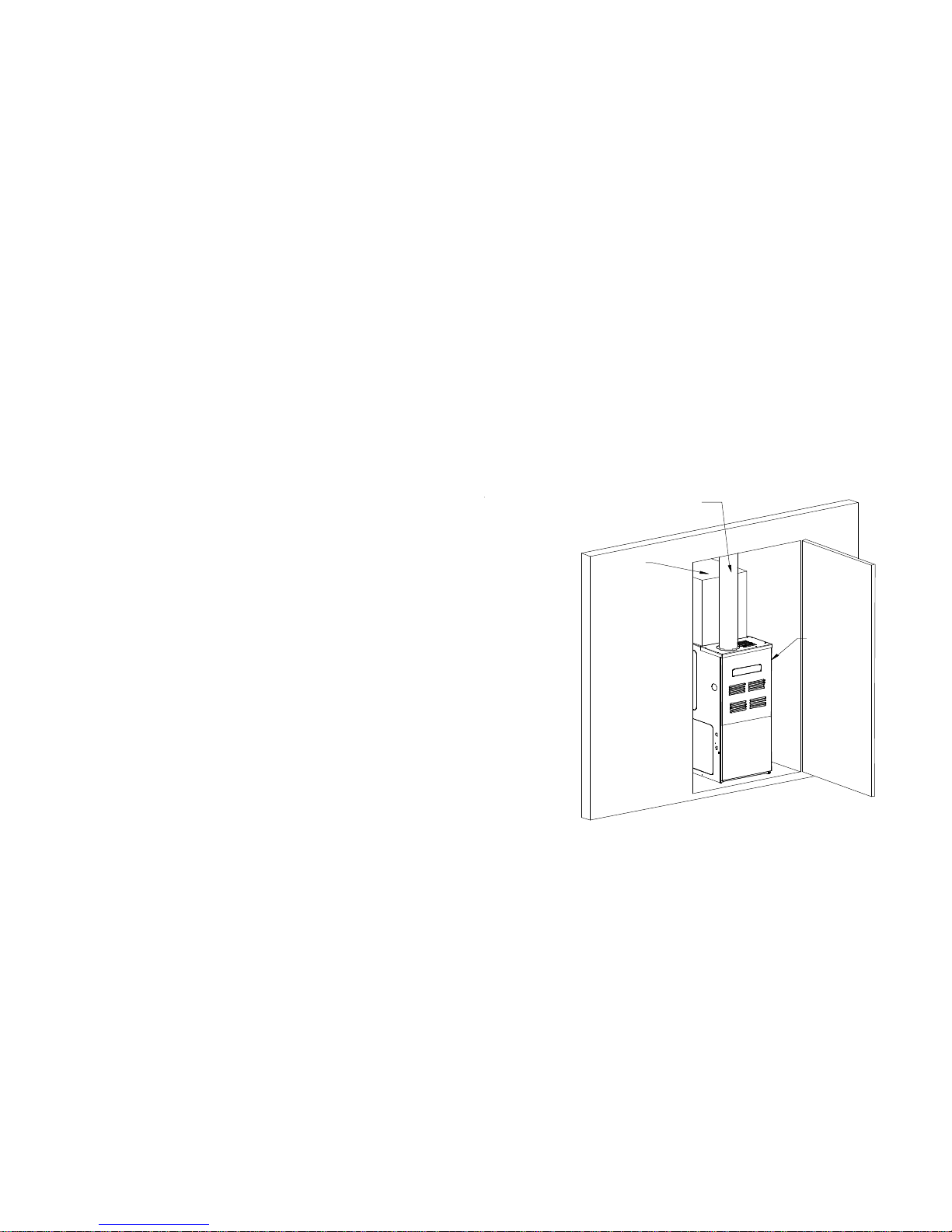
HORIZONTAL INSTALLATION (*MVC8 MODELS ONLY)
Line contact to framing is permitted when installed in the horizontal configuration. Line contact is defined as the portion of
the cabinet that is formed by the intersection of the top and
side. ACCESSIBILITY CLEARANCE, WHERE GREATER,
SHOULD T AKE PRECEDENCE OVER MINIMUM FIRE PROTECTION CLEARANCE. A gas-fired furnace for installation in
a residential garage must be installed so that the ignition source
and burners are located not less than eighteen inches (18")
above the floor and is protected or located to prevent physical
damage by vehicles. A gas furnace must not be installed directly on carpeting, tile, or other combustible materials other
than wood flooring.
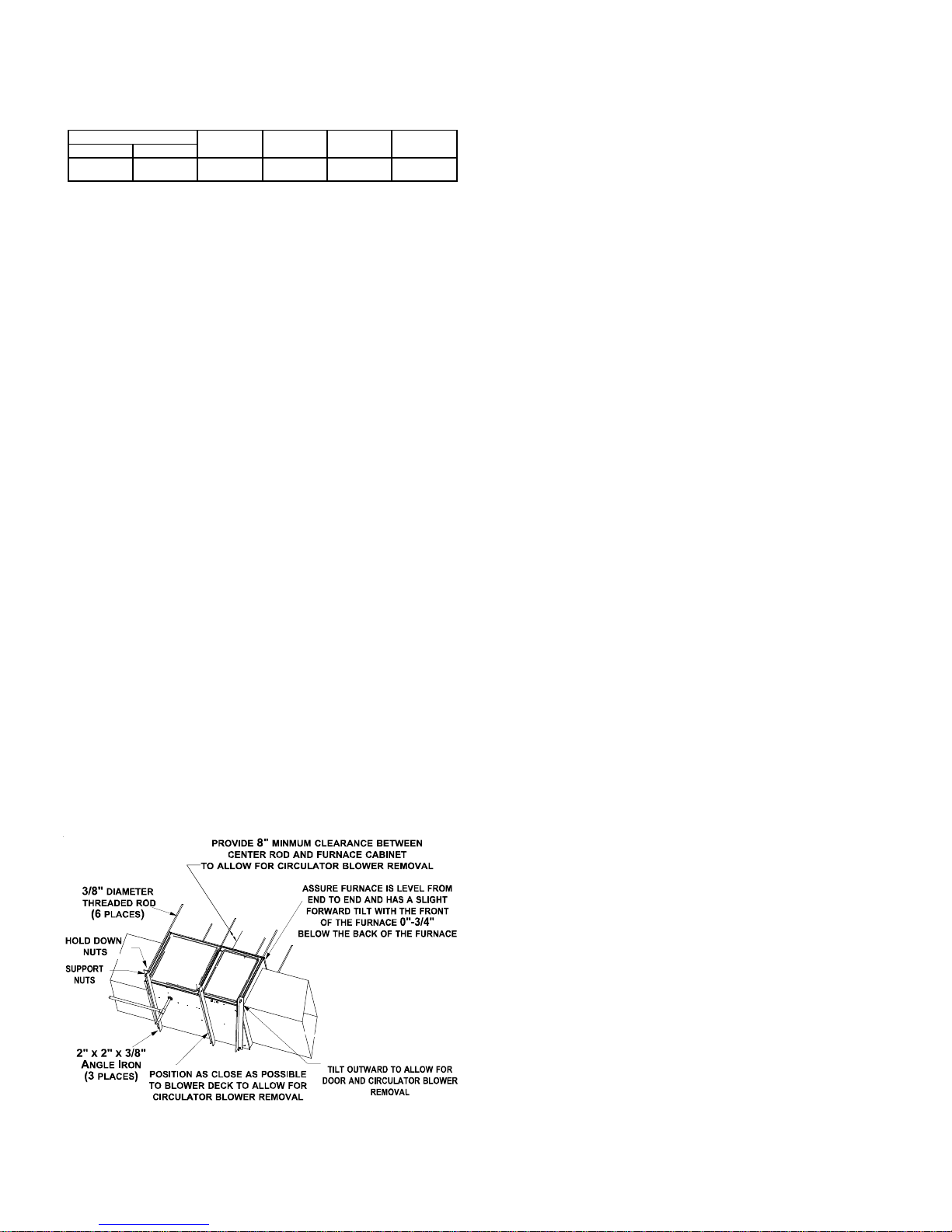
FURNACE SUSPENSION
If suspending the furnace from rafters or joist, use 3/8" threaded
rod and 2”x2”x3/8” angle iron as shown below. The length of
rod will depend on the application and the clearances necessary.
EXISTING FURNACE REMOVAL
NOTE: When an existing furnace is removed from a venting
system serving other appliances, the venting system may be
too large to properly vent the remaining attached appliances.
The following vent testing procedure is reproduced from the
American National Standard/National Standard of Canada
for Gas-Fired Central Furnaces ANSI Z21.47-Latest Edition, CSA-2.3-Latest Edition Section 1.23.1. The following
steps shall be followed with each appliance connected to the
venting system placed in operation, while any other appliances
connected to the venting system are not in operation:
a. Seal any unused openings in the venting system;
b. Inspect the venting system for proper size and
horizontal pitch, as required by the National Fuel Gas
Code, ANSI Z223.1 or the CAN/CSA B149 Installation
Codes and these instructions. Determine that there is
no blockage or restriction, leakage, corrosion and other
deficiencies which could cause an unsafe condition;
c. In so far as practical, close all building doors and
windows and all doors between the space in which
the appliance(s) connected to the venting system are
located and other spaces of the building. Turn on
clothes dryers and any appliance not connected to
the venting system. Turn on any exhaust fans, such
as range hoods and bathroom exhausts, so they shall
operate at maximum speed. Do not operate a summer
exhaust fan. Close fireplace dampers;
d. Follow the lighting instructions. Place the appliance
being inspected in operation. Adjust thermostat so
appliance shall operate continuously;
e. T est for draft hood equipped appliance spillage at the
draft hood relief opening after 5 minutes of main burner
operation. Use the flame of a match or candle;
f. After it has been determined that each appliance
connected to the venting system properly vents when
tested as outlined above, return doors, windows,
exhaust fans, fireplace dampers and any other gas
burning appliance to their previous conditions of use;
g. If improper venting is observed during any of the above
tests, the common venting system must be corrected.
Suspended Furnace
Corrections must be in accordance with the latest edition of
the National Fuel Gas Code NFP A 54/ANSI Z223.1 and/or CAN/
CSA B149 Installation Codes.
If resizing is required on any portion of the venting system, use
the appropriate table in Appendix G in the latest edition of the
National Fuel Gas Code ANSI Z223.1 and/or CAN/CSA B149
Installation Codes.
THERMOSTAT LOCATION
In an area having good air circulation, locate the thermostat
about five feet high on a vibration-free inside wall. Do not install
the thermostat where it may be influenced by any of the following:
9
Page 10
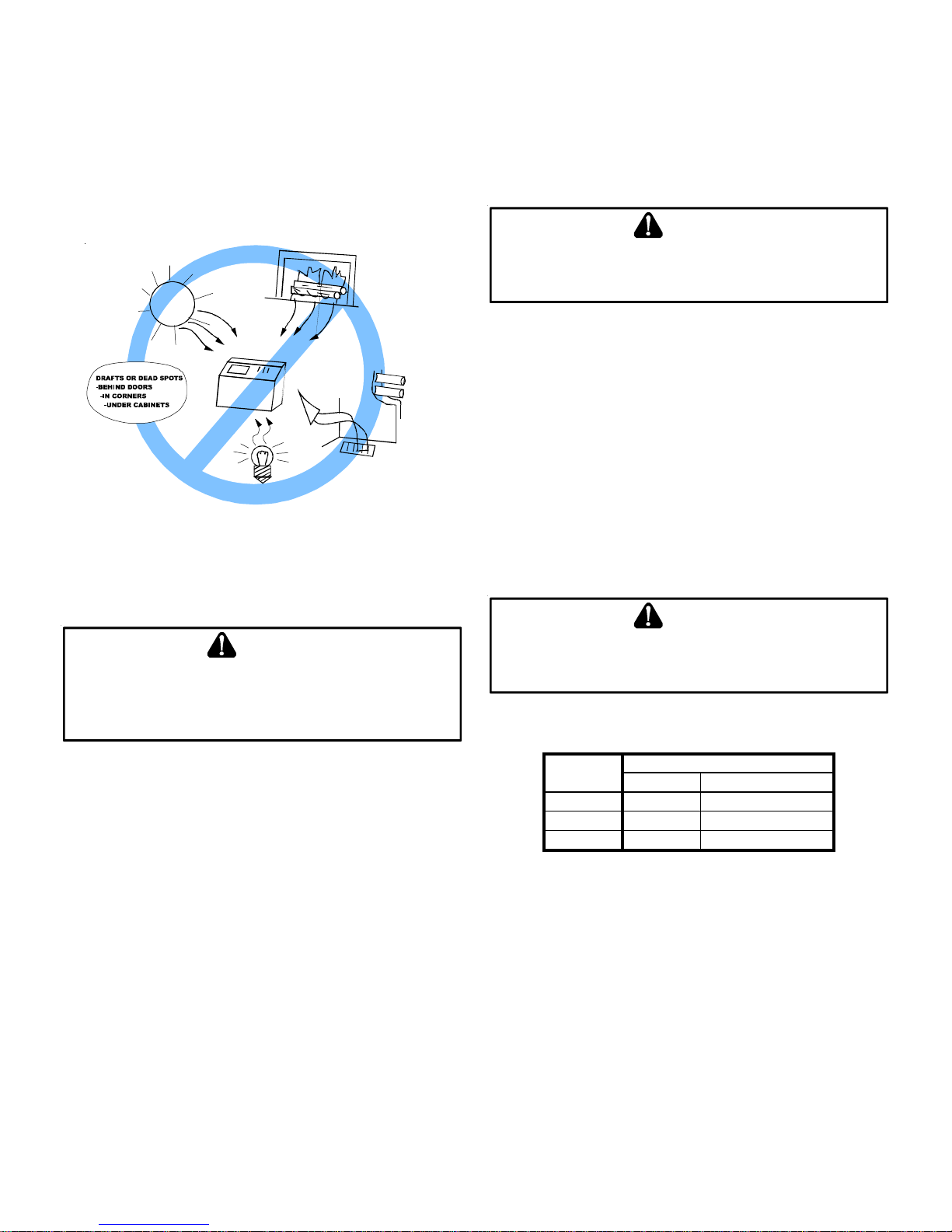
• Drafts, or dead spots behind doors, in corners, or under
cabinets.
• Hot or cold air from registers.
• Radiant heat from the sun.
• Light fixtures or other appliances.
• Radiant heat from a fireplace.
• Concealed hot or cold water pipes, or chimneys.
• Unconditioned areas behind the thermostat, such as
an outside wall.
HOT
COLD
Thermostat Influences
Consult the instructions packaged with the thermostat for mounting instructions and further precautions.
C
OMBUSTION AND VENTILA TION AIR REQUIREMENTS
This furnace must use indoor air for combustion. It cannot be
installed as a direct vent (i.e., sealed combustion) furnace.
Most homes will require outside air be supplied to the furnace
area by means of ventilation grilles or ducts connecting directly
to the outdoors or spaces open to the outdoors such as attics
or crawl spaces.
CATEGORY I VENTING (VERTICAL VENTING)
WARNING
TO
PREVENTPOSSIBLEPERSONALINJURYORDEATHDUETO
ASPHYXIATION,THISFURNACEMUSTBECATEGORY
VENTUSINGCATEGORY
III
VENTING
.
Category I Venting is venting at a non-positive pressure. A
furnace vented as Category I is considered a fan-assisted appliance and the vent system does not have to be “gas tight.”
NOTE: Single stage gas furnaces with induced draft blowers
draw products of combustion through a heat exchanger allowing, in some instances, common venting with natural draft appliances (i.e. water heaters). All inst allations must be vented in
accordance with National Fuel Gas Code NFP A 54/ANSI Z223.1
- latest edition. In Canada, the furnaces must be vented in accordance with the National Standard of Canada, CAN/CSA
B149.1 and CAN/CSA B149.2 - latest editions and amendments.
NOTE: The vertical height of the Category I venting system
must be at least as great as the horizontal length of the venting
system.
WARNING
I
VENTED
.DO
NOT
WARN ING
TO
AVOIDPROPERTYDAMAGE,PERSONALINJURYORDEATH
SUFFICIENTFRESHAIRFORPROPERCOMBUSTIONANDVENTILATIONOF
FLUEGASESMUSTBESUPPLIED
SUPPLIEDINTOTHEFURNACEAREA
.M
OSTHOMESREQUIREOUTSID EAIRBE
.
,
Improved construction and additional insulation in buildings have
reduced heat loss by reducing air infiltration and escape around
doors and windows. These changes have helped in reducing
heating/cooling costs but have created a problem supplying
combustion and ventilation air for gas fired and other fuel burning appliances. Appliances that pull air out of the house (clothes
dryers, exhaust fans, fireplaces, etc.) increase the problem by
starving appliances for air.
House depressurization can cause back drafting or improper
combustion of gas-fired appliances, thereby exposing building
occupants to gas combustion products that could include carbon monoxide.
If this furnace is to be installed in the same space with other
gas appliances, such as a water heater, ensure there is an
adequate supply of combustion and ventilation air for the other
appliances. Refer to the latest edition of the National Fuel Gas
Code NFPA 54/ANSI Z223.1 or CAN/CSA B149 Installation
Codes or applicable provisions of the local building codes for
determining the combustion air requirements for the appliances.
TO
PREVENTPOSSIBLEPERSONALINJURYORDEATHDUETO
ASPHYXIATION,COMMONVENTINGWITHOTHERMANUFACTURER’S
INDUCEDDRAFTAPPLIANCESISNOTALLOWED
.
The minimum vent diameter for the Category I venting system
is as shown:
MINIMUM VENT
MODEL
UPFLOW COUNTERFLOW
06 0 4 in c h 4 inc h
08 0 4 in c h 4 inc h
10 0 5 in c h 4 inc h
Under some conditions, larger vents than those shown above
may be required or allowed. When an existing furnace is re-
moved from a venting system serving other appliances, the
venting system may be too large to properly vent the remaining
attached appliances.
Upflow or Horizontal units are shipped with the induced draft
blower discharging from the top of the furnace. (“Top” is as
viewed for an upflow installation.) The induced draft blower can
be rotated 90 degrees for Category I venting. For horizontal
installations, a four inch single wall pipe can be used to extend
the induced draft blower outlet 1/2” beyond the furnace cabinet.
THIS PRODUCT IS NOT DESIGNED FOR COUNTERCLOCKWISE INDUCED DRAFT BLOWER ROT A TION.
10
Page 11
Vent the furnace in accordance with the National Fuel Gas
Code NFP A 54/ANSI Z223.1 - latest edition. In Canada, vent
the furnace in accordance with the National Standard of Canada,
CAN/CSA B149.1 and CAN/CSA B149.2 - latest editions and
amendments.
Venting
THIS FURNACE IS NOT DESIGN CERTIFIED TO BE HORIZONT ALL Y VENTED.
To rotate the induced draft blower clockwise, you will need to
purchase one (0270F01 1 19) chimney transition bottom kit.
1. Disconnect electrical power from the furnace.
2. Disconnect the induced draft blower power leads, flue
pipe, and pressure switch tubing.
3. Remove the round cutout from the right side of the wrapper.
4. Remove and save the four screws that fasten the induced
draft blower to the flue collector box.
5. Remove and save the three screws that hold the chimney
assembly to the induced draft blower .
6. Remove and save the four screws that fasten the chimney
top to the chimney bottom.
7. Remove the chimney transition bottom from the transition
bottom kit.
8. Install the chimney top with the four screws retained
from step 6 onto the new chimney transition bottom from
the transition bottom kit.
9. Install chimney assembly with the three screws retained
from step 5 onto the induced draft blower .
10.Reinstall the induced draft blower rotating it 90 degrees
clockwise from the original upflow configuration using
the four screws retained in step 3. Ensure the gasket
located between the induced draft blower and the collector
box is rotated accordingly .
1 1. Reconnect the induced draft blower power leads. NOTE:
If the wires are not long enough, pull extra wire from the
wire bundle in the blower compartment.
12. Reconnect the flue pipe, and the pressure switch tubing.
Ensure that all wires and the pressure switch tubing is
at least one inch from the flue pipe, or any other hot
surface.
13.Restore power to furnace.
WARNING
N
EVERALLOWTHEPRODUCTSOFCOMBUSTION,INCLUDINGCARBO N
MONOXIDE,TOENTERTHERETURNDUCTWORKORCIRCULATIONAIR
SUPPLY
.
E
XTERIOR MASONRY CHIMNEYS
(C
ATEGORY
I F
URNACES ONLY
)
An exterior masonry chimney is defined as a “Masonry” chimney exposed to the outdoors on one or more sides below the
roof line.” The ability to use a clay lined masonry chimney
depends on a parameter not associated with interior chimneys.
This variable is the geographic location of the installation. Researchers have discovered that the winter design temperatures
have a direct impact on the suitability of this type of venting. In
most situations, the existing masonry chimneys will require a
properly sized metallic liner.
WARNING
P
OSSIBILITYOFPROPERT YDAMAGE,PERSONALINJURYORDEATH
DAMAGINGCONDENSATIONCANOCCURINSIDEMASONRYCHIMNEYS
WHENASINGLEFAN‐ASSISTEDCATEGORY
FURNACE)ISVENTEDWITHOUTADEQUATEDILUTIONAIR
CONNECTAN
FURNACEISCOMMONVENTEDWITHADRAFTHOODEQUIPPED
APPLIANCEORTHECHIMNEYISLINEDWITHAMETALLINERORTYPE
METALVENT
SIZEDINACCORDANCEWITHTHEAPPROPRIATEVENTINGTABLES
80%
APPLIANCE,THEPOTENTIALFORCONDENSATIONDAMAGEMAYSTILL
EXISTWITHEXTREMELYCOLDCONDITIONS,LONGVENTCONNECTORS
EXTERIORCHIMNEYS,ORANYCOMBINATIONOFTHESECONDITIONS
HERISKOFCONDENSATIONDAMAGEISBESTAVOIDEDBYUSING
T
MASONRYCHIMNEYASAPATHWAYFORPROPERLYSIZEDMETALLINER
ORTYPE
80%
FURNACETOAMASONRYCHIMNEYUNLESSTHE
.ALL
INSTALLATIONSUSINGMASONRYCHIMNEYSMUSTBE
FURNACEISCOMMONVENTEDWITHADRAFTHOODEQUIPPED
B
METALVENT
.
I
APPLIANCE
(80%AFUE
.DO
NOT
.IFAN
B
,
.
Counterflow units are shipped with the induced draft blower
discharging from the top of the furnace. (“T op” as viewed for a
counterflow installation.)
Vent the furnace in accordance with the National Fuel Gas
Code NFP A54/ANSI Z223.1-latest edition. In Canada, vent the
furnace in accordance with the national standard of Canada,
CAN/CSA B149.1 and CAN/CSA B149.2- latest editions and
amendments.
11
Page 12
Wash
Roof Line
Clay Tile Size: 8" x 8" x12"
(Each x 24" Length )
Attic Floor
1/2" to 1" Air Space
Second Floor
Throat
Damper
Breech
Fan Assisted
Clean Out
Typical Multiple Flue Clay Tile Chimney
Forced Air
Furnace
F.A .F. Ven t
Connector
First Floor
Wate r Heate r
Vent Connector
Natural Draft
Wate r Heate r
Basement Floor
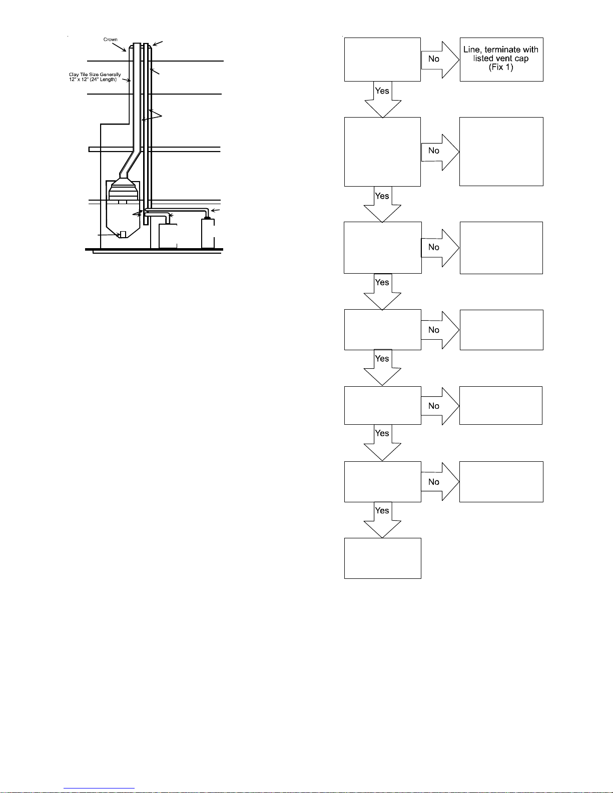
CHECKLIST SUMMARY
This checklist serves as a summary of the items to be checked
before venting an 80+ furnace into a masonry chimney . In addition, we recommend that a qualified serviceman use this checklist to perform a yearly inspection of the furnace venting system.
Proper Chimney
Termination?
(Check 1)
Chimney channel
free of solid and
liquid fuel
appliances?
(Check 2)
Crown in good
condition
(Check 3)
Cleanout free of
debris?
(Check 4)
Change venting
arrangements
(Fix 2)
Rebuild crown
(Fix 3)
and/or Reline
(Fix 4)
Reline
(Fix 4)
This checklist is only a summary . For det ailed information on
each of the procedures mentioned, see the paragraph referenced with each item.
This inspection is based upon a draft topical report, “Masonry
Chimney Inspection and Relining”, issued by the Gas Research
Institute. While not yet finalized, we believe this report represents the best information on this subject which is currently
available.
Liner in good
condition?
(Check 5)
Dilution air
available?
(Check 6)
Reline
(Fix 4)
Reline
(Fix 4)
Complete the
installation.
(Check 7)
CHECK 1 - PROPER CHIMNEY TERMINATION.
A masonry chimney used as a vent for gas fired equipment
must extend at least three feet above the highest point where it
passes through the roof. It must extend at least two feet higher
than any portion of a building within a horizontal distance of 10
feet. In addition, the chimney must terminate at least 3 feet
above any forced air inlet located within 10 feet. The chimney
must extend at least five feet above the highest connected equipment draft hood outlet or flue collar .
12
Page 13
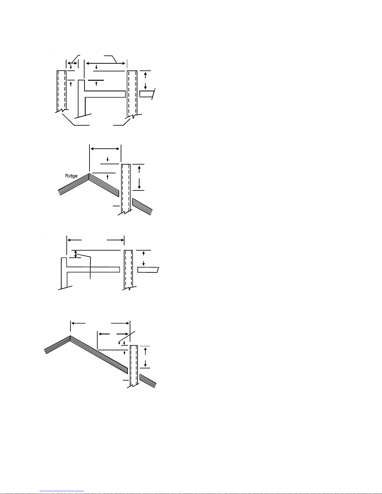
If the chimney does not meet these termination requirements,
but all other requirements in the checklist can be met, it may
be possible for a mason to extend the chimney . If this will not
be practical, see Fix 1.
10' or Less
2' Min.
2' Min.
Wall or
Parapet
Chimney
3' Min.
Appliances which burn propane (sometimes referred to as LP
(liquefied petroleum)) gas are considered gas-fired appliances.
CHECK 3 - CHIMNEY CROWN CONDITION.
Damage from condensate usually shows up first in the crown.
If any of the following trouble signs are present, the condition of
the crown is not satisfactory:
a) Crown leaning
b) Bricks missing
c) Mortar missing
d) Tile liner cracked
e) No tile liner
f ) Salt staining at mortar joints. (White stains, and mortar
becomes sandy and/or erodes.)
10' or Less
2' Min.
3' Min.
Chimney
Termination 10 Feet Or Less From Ridge, Wall or Parapet
More than 10’
3’ Min.
NOTE:
No Height
above parapet
Wall or
Parapet
Ridge
required when distance
from walls o r parapet is
more than 10 feet.
More than 10’
10’
2” Min.
Chimney
Height above any
roof surface within
10 feet horizontally.
3’ Min.
For problems a, b, or c, see Fix 3. If problems d, e, or f are
present, see Fix 4. IMPORT ANT : It may be necessary to follow
both Fix 3 and Fix 4.
CHECK 4 - DEBRIS IN CLEANOUT.
A cleanout (dropleg) must be present such that the upper edge
of the cleanout cover is at least 12 inches below the lower edge
of the lowest chimney inlet opening.
A chimney without a cleanout could become partially blocked
by debris. If no cleanout is present, the chimney must be relined (Fix 4). Remove the cleanout cover, and examine the
cleanout for debris. If significant amounts of any of the following
are found:
• Fuel oil residue
• Bricks
• Mortar or sand
• Pieces of the tile liner
• Rusted pieces of the metallic liner - reline the chimney
(Fix 4).
CHECK 5 - LINER CONDITION.
If a metal liner is present, it must be checked. It cannot be
assumed that all existing metal liners are correctly installed
and in good condition.
Remove the lowest existing vent connector, and examine the
inside of the elbow or tee at the base of the liner. A small amount
of soot may be considered acceptable, provided the installer
vacuums it away. If rusted pieces of the liner have collected
here, the metal liner must be removed and replaced (Fix 4).
Chimney
Termination More Than 10 Feet From Ridge, Wall or Parapet
CHECK 2 - ANY SOLID OR LIQUID FUEL APPLIANCES VENTED
THIS CHIMNEY CHANNEL
INTO
Solid fuel appliances include fireplaces, wood stoves, coal furnaces, and incinerators.
Liquid fuel appliances include oil furnaces, oil-fired boilers and
oil-fired water heaters.
Next, gently tap the inside of the liner with a Phillips screwdriver. If the screwdriver perforates the liner, or if the tapping
does not sound like metal hitting metal, the liner must be removed and replaced (Fix 4).
Remember that all appliances must be vented inside the liner.
Venting one appliance inside the liner and another appliance
outside the liner is not acceptable.
13
Page 14

Next, use a flashlight and small mirror to sight up the liner. B
vent must be supported so as to not come into direct contact
with the chimney walls or tile liner. If it is not, it can probably be
rehung so as to be acceptable. A thimble or fire stop may be
helpful here.
Flexible liners should be hung straight or nearly straight. If it is
spiraled in the chimney and in good condition, it should be
rehung. To do this, break the top seal; pull up and cut off the
excess liner length, and refit the top seal. Use caution when
doing this, as the cut edges of flexible liners may be sharp.
The surfaces of the liner must be physically sound. If gaps or
holes are present, the metal liner must be removed and replaced (Fix 4). Finally , confirm that the metal liner is the correct size for the appliances to be installed. Use the GAMA
tables and rules.
If a metal liner is not present, a clay tile liner must be present,
or the chimney must be lined (Fix 4).
Use a flashlight and small mirror at the cleanout or vent connector to inspect the clay tile liner. If any of the following problems are present:
• Tile sections misaligned
• Tile sections missing
• Gaps between tile sections
• Signs of condensate drainage at the cleanout or vent
connectors
• Mortar protruding from between tile sections
• Use of sewer pipe or drainage pipe rather than an
approved fire clay tile reline the chimney (Fix 4).
Next, measure the size of the liner. It may be possible to do
this from the cleanout. The liner must be at least as large as
the minimum size established by the tables in National Fuel
Gas Code NFPA 54/ANSI Z223.1 - latest edition and in the
National Standard of Canada, CAN/CSA B149.1 and CAN/CSA
B149.2 - latest editions and amendments. If the liner is too
small or too large, then the chimney must be relined (Fix 4).
CHECK 6 - DILUTION AIR.
If gas-fired appliances are to be vented into a clay tile liner, a
source of dilution air is required.
Dilution air cannot be obtained through:
• Induced draft appliances
• Natural draft appliances with vent dampers
CHECK 7 - COMPLETE THE INSTALLATION.
If Checks 1 through 6 have been satisfactory , and the liner is an
acceptable size as determined by the tables in National Fuel
Gas Code NFPA 54/ANSI Z223.1 - latest edition and in the
National Standard of Canada, CAN/CSA B149.1 and CAN/CSA
B149.2 - latest editions and amendments, then the clay tile
liner can probably be used as a vent for the gas appliances.
However, the inst aller must keep in mind the following factors
which may render the tile liner unsuitable for use as a vent:
• Extremely cold weather
• Long vent connectors
• Masonry chimneys with no air gap between the liner
and the bricks. (In practice, this can be difficult to
detect.)
• Exterior chimneys (The tables in National Fuel Gas
Code NFP A 54/ANSI Z223.1 - latest edition and in the
National St andard of Canada, CAN/CSA B149.1 and
CAN/CSA B149.2 - latest editions and amendments
assume interior chimneys.)
If, in the judgment of the local gas utility , installer , and/or local
codes; one or more of the above factors is likely to present a
problem, the chimney must be relined (Fix 4).
FIX 1 - LINER TERMINATION
Any cap or roof assembly used with a liner must be approved
by the liner manufacturer for such use. The liner and cap/roof
assembly must then terminate above the roof in accordance
with the manufacturer’s instructions.
In some cases, a shorter extension above the roof may be
possible with a liner than would be required with a masonry
chimney.
For further information on relining, see Fix 4.
FIX 2 -CHANGE VENTING ARRANGEMENTS
If the masonry chimney has more than one channel, it may be
possible to vent the gas appliances into one channel and vent
the solid or liquid fuel appliance(s) into another channel(s). Do
not vent an 80+ Furnace inside of a metal liner with other appliances vented outside the liner.
Alternatively , the homeowner may agree to discontinue use of
the fireplace (solid fuel appliance). If so, the tile liner must be
cleaned to remove creosote buildup. The fireplace opening must
then be permanently sealed.
Sufficient dilution air can ordinarily be obtained through the draft
hood of a natural draft appliance only if the appliance’s vent
connector does not include a vent damper. If dilution air will not
be available, the chimney must be relined (Fix 4).
If oil-fired appliance(s) are being replaced by gas-fired
appliance(s), the tile liner must first be cleaned to remove the
fuel oil residue.
If none of the above options is practical, the furnace may need
to be vented vertically with a B Vent.
Under some conditions, a 90%+ furnace could be installed rather
than an 80% furnace. The 90%+ furnace can be vented horizontally or vertically through PVC pipe.
14
Page 15
FIX 3 - REBUILD THE CROWN
If the chimney crown is damaged, a qualified mason must repair it in accordance with nationally recognized building codes
or standards. One such standard which may be referenced is
the Standard for Chimneys, Fireplaces, Vents, and Solid Fuel
Burning Appliances, ANSI/NFPA 21 1.
FIX 4 - RELINING
Relining options include B vent and flexible liners.
If the chimney has diagonal offsets, B vent probably cannot be
used.
If B vent is to be used, it must be supported adequately . Sup-
ports (such as fire stops or thimbles) must be used to prevent
the B vent from coming into direct contact with the tile liner or
chimney walls. Direct contact would result in higher heat loss,
with an increased possibility of poor venting system performance.
It is not acceptable to vent one appliance inside the B vent and
other appliances outside. The excess space between the B
vent and the chimney walls must be covered at the top of the
chimney by a weatherproof, corrosion resistant flashing.
The B vent should then be topped with a listed vent cap. The
listed vent cap will, when installed per the manufacturer’s instructions, prevent problems due to rain, birds, or wind effects.
A B-vent installed as described in this section is considered to
be an enclosed vent system, and the sizing tables in National
Fuel Gas Code NFPA 54/ANSI Z223.1 - latest edition and in
the National Standard of Canada, CAN/CSA B149.1 and CAN/
CSA B149.2 - latest editions and amendments may be used.
For sizing of flexible liners, see Note 22 and the tables in the
National Fuel Gas Code NFP A 54/ANSI Z223.1 - latest edition
and in the National Standard of Canada, CAN/CSA B149.1 and
CAN/CSA B149.2 - latest editions and amendments.
T o inst all the liner, read and follow the liner manufacturer’s instructions and your local codes. Excess liner length should be
pulled out of the chimney and cut off. Use caution when doing
this, as the cut edges of flexible liners may be sharp. Do not
spiral excess liner inside of the chimney . Support the liner as
recommended by the liner manufacturer.
Some manufacturers of flexible liners offer an insulation sleeve
designed to be added to the liner before it is installed in the
chimney. (Poured insulation, either vermiculite or other materials, is no longer recommended.) Insulation will need to be added
to the flexible liner if:
• It is required by the liner manufacturer’s instructions.
• The previous liner was properly sized and installed,
and suffered from condensation damage.
• It is required by your local building codes.
Even if none of those three conditions exist which require additional liner insulation, the installer may wish to consider it if:
• The local climate is very cold.
• The chimney is very tall.
• The vent connectors used are very long or have a large
number of elbows.
• Local experience indicates that flexible liners installed
without insulation are likely to have condensation
problems.
Insulation must be selected and installed in accordance with
the liner manufacturer’s instructions.
If a flexible liner is to be used, it must be made of the proper
materials:
• For most residential applications, an aluminum liner
should be acceptable.
• If the combustion air supplied to the furnace will be
contaminated with compounds containing chlorine or
fluorine, a liner of AL 29-4C stainless steel should be
used. Common sources of chlorine and fluorine
compounds include indoor swimming pools and
chlorine bleaches, paint strippers, adhesives, paints,
varnishes, sealers, waxes (which are not yet dried)
and solvents used during construction and remodeling.
V arious commercial and industrial processes may also
be sources of chlorine/fluorine compounds.
• Heavier gauge 300 and 400 series stainless steel liners
were developed for use with oil or solid fuel appliances.
They are not suitable for use with gas-fired appliances.
Flexible liners specifically intended and tested for gas
applications are listed in the UL “Gas and Oil
Equipment Directory”. (UL S tandard 1777).
Finally, cap the chimney and terminate the liner in accordance
with the liner manufacturer’s instructions.
E
LECTRICAL CONNECTIONS
WARNING
HIGHVOLTAGE!
TO
AVOIDTHERISKOFELECTRICALSHOCK,WIRINGTO
THEUNITMUSTBEPOLARIZEDANDGROUNDED
.
WARNING
HIGHVOLTAGE!
TO
AVOIDPERSONALINJURYORDEATHDUETO
ELECTRICALSHOCK,DISCONNECTELECTRICALPOWER
BEFORESERVICINGORCHANGINGANYELECTRICAL
WIRING
.
CAUTION
L
ABELALLWIRESPRIORTODISCONNECTIONWHENSERVICING
CONTROLS
OPERATION
.W
IRINGERRORSCANCAUSEIMPROPERANDDANGEROUS
.V
ERIFYPROPEROPERATIONAFTERSERVICING
.
15
Page 16

WARN ING
HIGHVOLTAGE!
TO
AVOIDTHERISKOFINJURY,ELECTRICALSHOCKOR
DEATH,THEFURNACEMUSTBEELECTRICALLY
GROUNDEDINACCORDANCEWITHLOCALCODESORIN
THEIRABSENCE,WITHTHELATESTEDITIONOFTHE
N
ATIONALELECTRICCODE
.
WIRING HARNESS
The wiring harness is an integral part of this furnace. Field
alteration to comply with electrical codes should not be required. Wires are color coded for identification purposes. Refer to the wiring diagram for wire routings. If any of the original
wire as supplied with the furnace must be replaced, it must be
replaced with wiring material having a temperature rating of at
least 105° C. Any replacement wiring must be a copper conductor.
115 VOLT LINE CONNECTIONS
Before proceeding with electrical connections, ensure that the
supply voltage, frequency , and phase correspond to that specified on the unit rating plate. Power supply to the furnace must
be NEC Class 1, and must comply with all applicable codes.
The furnace must be electrically grounded in accordance with
local codes or, in their absence, with the latest edition of The
National Electric Code, ANSI NFPA 70 and/or The Canadian
Electric Code CSA C22.1.
Use a separate fused branch electrical circuit containing properly sized wire, and fuse or circuit breaker. The fuse or circuit
breaker must be sized in accordance with the maximum overcurrent protection specified on the unit rating plate. An electrical disconnect must be provided at the furnace location.
Connect hot, neutral, and ground wires as shown in the wiring
diagram located on the unit’s blower door .
Line polarity must be observed when making field connections.
Line voltage connections can be made through either the right
or left side panel. The furnace is shipped configured for a right
side electrical connection with the junction box located inside
the burner compartment (blower compartment for downflows).
To make electrical connections through the opposite side of
the furnace, the junction box must be relocated to the other
side of the burner (or blower) compartment prior to making
electrical connections. T o relocate the junction box, follow the
steps shown below.
Line voltage connections can be made through either the right
or left side panel. The furnace is shipped configured for a right
side electrical connection. To make electrical connections
through the opposite side of the furnace, the junction box must
be relocated to the left side prior to making electrical connections. T o relocate the junction box, perform the following step s.
WARNING
TO
PREVENTPERSONALINJURYORDEATHDUETOELECTRICSHOCK
DISCONNECTELECTRICALPOWERBEFOREINSTALLINGORSERVICINGTHIS
UNIT
.
,
1. Remove both doors from the furnace.
2. Remove and save the screws holding the junction box to
the right side of the furnace.
3. Models that have the junction box located in the burner
or blower compartment will need to move the junction
box directly over .
4. Attach the junction box to the left side of the furnace,
using the screws removed in step 2.
5. Check the location of the wiring. Confirm that it will not
be damaged by heat from the burners or by the rotation
of the fan. Also confirm that wiring location will not
interfere with filter removal or other maintenance.
After the junction box is in the desired location, use washers to
connect field-supplied conduit to the junction box in accordance
with NEC and local codes. Connect hot, neutral, and ground
wires as shown in the furnace wiring diagram. The wires and
ground screw are located in the furnace junction box.
NOTE: In downflow applications the power leads should be
routed through the supplied wire tabs when locating junction
box to the left side.
Low voltage wires may be connected to the terminal strip.
IMPORT ANT NOTE: T o avoid possible equipment malfunction,
route the low voltage wires to avoid interference with filter removal or other maintenance.
WARNING
HIGHVOLTAGE!
TO
AVOIDTHERISKOFINJURY,ELECTRICALSHOCKOR
DEATH,THEFURNACEMUSTBEELECTRICALLY
GROUNDEDINACCORDANCEWITHLOCALCODESORIN
THEIRABSENCE,WITHTHELATESTEDITIONOFTHE
N
ATIONALELECTRICCODE
.
NOTE: Wire routing must not to interfere with circulator blower
operation, filter removal, or routine maintenance.
JUNCTION BOX RELOCATION
WARN ING
E
DGESOFSHEETMETALHOLESMAYBESHARP
PRECAUTIO NWHENREMOVINGHOLEPLUGS
.USE
.
GLOVESASA
To ensure proper unit grounding, the ground wire should run
from the furnace ground screw located inside the furnace junction box all the way back to the electrical panel. NOTE: Do
not use gas piping as an electrical ground. To confirm proper
unit grounding, turn off the electrical power and perform the
following check.
16
Page 17

1. Measure resistance between the neutral (white)
connection and one of the burners.
2. Resistance should measure 10 ohms or less.
This furnace is equipped with a blower door interlock switch
which interrupts unit voltage when the blower door is opened for
servicing. Do not defeat this switch.
24 VOLT THERMOSTAT WIRING
Y C
Remote
Condensing Unit
(Single-Stage Cooling)
R
R
NEU
Furnace Integrated
Control Module
Dehumidistat
[Optional]
IMPORTANT NOTE
W
IREROUTINGMUSTNOTINTERFEREWITHCIRCULATORBLOWER
OPERATION,FILTERREMOVA LORROUTINEMAINTENANCE
REMOVA BLEPLUGCONNECTORISPROVIDEDWITHTHECONTROLTO
A
MAKETHERMOSTATWIRECONNECTIONS
WIRECONNECTIONSMADETOTHEPLUG,ANDREPLACED
STRONGLY
WIRESINTOASINGLETERMINAL
ENSUREONE
DOSOMAYRESULTININTERMITTENTOPERATION
RECOMMENDEDTHATYOUDONOTCONNECTMULTIPLE
18AWG
WIREISUSEDFOREACHTERMINAL
.T
HISPLUGMAYBEREMOVED
.ITIS
.W
IRENUTSARERECOMMENDEDTO
.
.
.F
AILURETO
,
IMPORTANT NOTE
W
HENUSINGANON‐COMMUNICATINGTHERMOSTAT,DIPSWITCHES
S1‐3
MUSTBESETTOMATCHTHETHERMOSTATTYPE
STAGETHERMOSTAT,SET
2‐
STAGETHERMOSTAT,SET
WHENASINGLESTAGETHERMOSTATISCONNECTED
S
TAGEHEATINGTHERMOSTATAPPLICATIONSECTIONFORDETAILS
S1‐3TOON.W
S1‐3TOOFF.S1‐4
.W
HENUSINGA
HENUSINGASINGLE
SHOULDBEUSEDONLY
.SEES
INGLE
‐
.
As a two-stage non-communicating furnace, the furnace integrated control module provides terminals for both “W1” and “W2”,
and “Y1” and “Y2” thermostat connections. This allows the
furnace to support the following system applications: ‘TwoStage Heating Only’, ‘T wo-St age Heating with Single Stage Cooling’, and ‘Two-S tage Heating with T wo-St age Cooling’. Refer to
the following figures for proper connections to the integrated
control module.
Low voltage connections can be made through either the right
or left side panel. Thermostat wiring entrance holes are located
in the blower compartment. The following figure shows connections for a “heat/cool system”.
NOTE: To apply a single-stage Heating Thermostat, the thermostat
selector switch on the Integrated Control Module must be set on
single-stage.
Thermostat - Single -Stage Heating with Single-Stage
Cooling
_______________________
R
Furnace Integrated
Control Module
Dehumidistat
[Optional]
Y C
Remote
Condensing Unit
(Single-Stage Cooling)
R
NEU
Thermostat - Two-Stage Heating with Single-Stage Cooling
_______________________
Y2
Y2
Y2
Remote
Condensing Unit
(Two-Stage Cooling)
Thermostat - Two-Stage Heating with Two-Stage Cooling
Thermostat Wiring Diagrams
W1 W2
W1 W2
NEU
Furnace Integrated
Dehumidistat
[Optional]
Control Module
SINGLE-STAGE HEATING THERMOSTAT APPLICATION
This furnace is equipped with a 40 V A transformer to facilitate
use with most cooling equipment. Consult the wiring diagram,
located on the blower compartment door , for further details of
1 15 V olt and 24 V olt wiring.
NOTE: For single stage cooling applications, a jumper must
be located between Y1 and Y2 at the furnace control in order
to achieve the desired single stage cooling airflow. Use of
ramping profiles and dehumidification features requires a jumper
between Y1 and O and Y1 and DEHUM, respectively .
NOTE: Thermostat “R” required if outdoor unit is equipped with
a Comfort Alert™ module or if the outdoor unit is a part of the
ComfortNet™ family of equipment AND is wired as a noncommunicating system.
A single-stage thermostat with only one heating stage may
be used to control this furnace. The application of a singlestage thermostat offers a timed transition from low to high
fire. The furnace will run on low stage for a fixed period of time
before stepping up to high stage to satisfy the thermostat’s
call for heat. The delay period prior to stepping up can be set
at either a fixed 5 minute time delay or a load based variable
time between 1 and 12 minutes (AUTO mode). If the AUT O
mode is selected, the control averages the cycle times of the
previous three cycles and uses the average to determine the
time to transition from low stage to high stage.
17
Page 18

T o use a single-stage thermostat, turn of f power to the furnace,
move the thermostat selection DIP switch to the OFF position.
Set the desired transition time by setting the transition delay
DIP switch to the desired ON/OFF position. Turn power back
on. Refer to the following figure.
Heat OFF Delay
DIP Switches
ONOFF
3
4
Thermostat
Stage De lay
S1
Move to the ON position
to select two-stage
thermostat or OFF to
select single stage
thermostat
Move to the ON position
to select Auto transition
delay or OFF for 5 minute
transition delay
24 VOLT DEHUMIDISTAT WIRING
The optional usage of a dehumidistat allows the furnace’s circulator blower to operate at a slightly lower speed (85% of
desired speed) during a combined thermostat call for cooling
and dehumidistat call for dehumidification. This can be done
through an independent dehumidistat or through a thermostat’s
DEHUM terminal (if available). This lower blower speed enhances
dehumidification of the conditioned air as it passes through the
AC coil. For proper function, a dehumidistat applied to this
furnace must operate on 24 VAC and utilize a switch which
opens on humidity rise. Refer to the “Thermostat Wiring Diagrams” figure for additional wiring details.
FOSSIL FUEL APPLICATIONS
This furnace can be used in conjunction with a heat pump in a
fossil fuel application. A fossil fuel application refers to a combined gas furnace and heat pump installation which uses an
outdoor temperature sensor to determine the most cost efficient means of heating (heat pump or gas furnace).
A heat pump thermostat with three stages of heat is required to
properly use a two-stage furnace in conjunction with a heat
pump. Refer to the fossil fuel kit installation instructions for
additional thermostat requirements.
Strictly follow the wiring guidelines in the fossil fuel kit installation instructions. All furnace connections must be made to the
furnace two-stage integrated control module and the “FURNACE” terminal strip on the fossil fuel control board.
115 VOLT LINE CONNECTION OF ACCESSORIES (HUMIDIFIER
ELECTRONIC AIR CLEANER)
AND
WARNING
HIGHVOLTAGE!
TO
AVOIDPERSONALINJURYORDEATHDUETO
ELECTRICALSHOCK,DISCONNECTELECTRICALPOWER
BEFORESERVICINGORCHANGINGANYELECTRICAL
WIRING
.
T o inst all/connect a dehumidistat:
1. Turn OFF power to furnace.
2. T o enable the dehumidify function on the integrated control
module, set the dehumidification ENABLE dipswitch from
OFF to ON.
3. Secure the dehumidistat neutral wire (typically the white
lead) to the terminal marked “DEHUM” on the furnace
integrated control module.
4. Secure the dehumidistat hot wire (typically the black
lead) to the terminal marked “R” on the furnace integrated
control module.
5. Secure the dehumidistat ground wire (typically the green
lead) to the ground screw on the furnace junction box.
NOTE: Ground wire may not be present on all
dehumidistats.
6. Turn ON power to furnace.
Once the switch is set, the dehumidify function is enabled during a combination call for cooling (T-S tat) and dehumidification
(DEHUM-Stat).
ON
OFF
1
2
DEHUM
TRIM ENABLE
S5
Move to the ON position
to enable dehumidification
The furnace integrated control module is equipped with line
voltage accessory terminals for controlling power to an optional
field-supplied humidifier and/or electronic air cleaner.
The accessory load specifications are as follows:
Humidifier 1.0 Amp maximum at 120 VAC
Electronic Air Cleaner 1.0 Amp maximum at 120 VAC
Turn OFF power to the furnace before installing any accessories.
Follow the humidifier or air cleaner manufacturers’ instructions for
locating, mounting, grounding, and controlling these accessories.
Accessory wiring connections are to be made through the 1/4"
quick connect terminals provided on the furnace integrated control
module. The Electronic air cleaner hot terminal is identified as
EAC. It is necessary to remove the protective tab on the board
cover to access the EAC T erminal. The EAC neutral terminal
is identified as NEUTRAL. A line voltage humidifier may be
connected between one of the HUM contacts and NEUTRAL.
The other HUM contact must be fed from the L1 terminal.
All field wiring must conform to applicable codes. Connections
should be made as shown in the following figure.
18
Page 19

Accessories Wiring
If it is necessary for the installer to supply additional line voltage wiring to the inside of the furnace, the wiring must conform
to all local codes, and have a minimum temperature rating of
105°C. All line volt age wire splices must be made inside the
furnace junction box.
The integrated furnace control HUM (dry contacts) are closed
whenever the inducer is energized in a non-communicating installation. When used with a CTK02** communicating thermostat, the HUM terminals are closed whenever there is a call for
humidity . The integrated control module electronic air cleaner terminals (EAC) are energized with 1 15 volts whenever the circulator
blower is energized.
In addition, the control is equipped with a dedicated humidification relay which is available through ¼ inch terminals HUM-IN
and HUM-OUT. Similar to the HUM terminal, when utilizing
legacy connections, this relay will be closed during normal
heating operation (115VAC must be present on the HUM-IN
terminal to take advantage of HUM-OUT). However , the control
can provide additional humidification features when wired to a
communicating thermostat (1, 2, R, C connections). If the
communicating thermostat is not capable of providing a humidification call, this dedicated relay will function exactly as
mentioned above with a legacy setup. If the communicating
thermostat is capable of providing a humidification call the user
is now provided with 3 modes of operations which can be selected within the thermostat user menu.
1. ON: Humidifier is turned on with a heat demand.
2. OFF: Humidifier remains off (relay never closes).
3. IND: Humidifier will cycle with humidification demand, independent of heat demand. This mode allows the user to
select one of 4 fan speeds (25, 50, 75, and 100%).
NEUTRAL
HUM-IN
HUM-OUT
24 VOLT HUMIDIFIER
A 24 volt humidifier can be powered by feeding one of the HUM
terminals with a field installed wire from the R terminal or by
connecting to the NO side of the low fire pressure switch.
AUXILIARY ALARM SWITCH
The control is equipped with a 24VAC Auxiliary Alarm Input (12
inch purple wire attached to pin 6 of 15 pin connector) which
can be utilized with communicating mode setups (typically used
for condensate switch wiring but could be used with compatible C02 sensors or Fire Alarms).
Legacy mode use
In a legacy system (Non-communicating), this auxiliary alarm
input is not operational. Any auxiliary alarm switch must be
used to interrupt Y1 signal either to IFC or to UC.
Communication mode use
This feature can be activated or deactivated through the thermostat user menus. By default, an AUX switch is normally
closed and opens when the water level in the evaporator coil
base pan reaches a particular level. The control will respond by
turning off the outdoor compressor and display the proper fault
codes. If the AUX switch is detected closed for 30 seconds,
normal operation resumes and error messages are no longer
displayed. Installer must wire control voltage (24V AC) to AUX
switch to ensure the Auxiliary Alarm Input has 24VAC during
normal operation.
GAS S
The furnace rating plate includes the approved furnace gas input rating and gas types. The furnace must be equipped to
operate on the type of gas applied. This includes any conversion kits required for alternate fuels and/or high altitude.
UPPLY AND PIPING
CAUTION
TO
PREVENTUNRELIABLEOPERATIONOREQUIPMENTDAMAGE,THE
INLETGASSUPPLYPRESSUREMUSTBEASSPECIFIEDONTHEUNIT
RATINGPLATEWITHALLOTHERHOUSEHOLDGASFIREDAPPLIANCES
OPERATING
.
Inlet gas supply pressures must be maintained within the ranges
specified in the following table. The supply pressure must be
constant and available with all other household gas fired appliances operating. The minimum gas supply pressure must be
maintained to prevent unreliable ignition. The maximum must
not be exceeded to prevent unit overfiring.
19
Page 20

NOTE: Do not remove the gas valve inlet plug before the gas
line is installed. Replace if water or debris has been introduced.
INLET GAS SUPPLY PRESSURE
Natural Gas Minimum: 4.5" w.c. Maximum: 10.0" w.c.
Propane Gas Minimum: 11.0" w.c. Maximum: 13.0" w.c.
NOTE: Adjusting the minimum supply pressure below the limits
in the above table could lead to unreliable ignition. Gas input to
the burners must not exceed the rated input shown on the
rating plate. Overfiring of the furnace can result in premature
heat exchanger failure. Gas pressures in excess of 13 inches
water column can also cause permanent damage to the gas
valve.
At all altitudes, the manifold pressure must be within 0.3 inches
w.c. of that listed in the S pecification Sheet applicable to your
model for the fuel used. At all altitudes and with either fuel, the
air temperature rise must be within the range listed on the furnace nameplate. Should this appliance be converted to LP,
refer to the instructions included in the factory authorized LP
conversion kit.
This unit is configured for natural gas. The appropriate
manufacturer’s propane gas conversion kit, must be applied for
propane gas installations. Refer to the “Propane Gas and/or
High Altitude Inst allations” section for details.
If converting to LP gas, it is recommended that an LPLP0* kit
also be installed. The use of this kit will prevent the furnace
from firing when the LP gas supply pressure is too low to support proper combustion.
Consult the furnace S pecification Sheet for a listing of appropriate manufacturer’s kits for propane gas and/or high altitude installations. The indicated kits must be used to insure safe and
proper furnace operation. All conversions must be performed
by a qualified installer , or service agency .
GAS PIPING CONNECTIONS
WARNING
TO
AVOIDPOSSIBLEUNSATISFACTORYOPERATIONOFEQUIPMENT
DAMAGEDUETOUNDERFIRINGOREQUIPMENT,USETHEPROPERSIZE
OFNATURAL/PROPANEGASPIPINGNEEDEDWHENRUNNINGPIPEFROM
THEMETER/TANKTOTHEFURNACE
.
HIGH ALTITUDE DERATE
IMPORT ANT NOTE: The furnace will naturally derate itself with
altitude. Do not attempt to increase the firing rate by changing
orifices or increasing the manifold pressure. This can cause
poor combustion and equipment failure.
High altitude installations may require both a pressure switch
and an orifice change. These changes are necessary to compensate for the natural reduction in the density of both the gas
fuel and the combustion air at higher altitude.
For installations above 7000 feet, please refer to your distributor for required kit(s).
Gas
Altitude Kit Orifice
Natural Non e #45 3.5" w.c. 1.9" w.c. None
Propane LPM-06 #55 10.0" w.c . 6.0" w.c. None
NOTE: In Canada, gas furnaces are only cert ified to 4500 feet.
0-7000
Manifold Pressure Pressure
High StageLow Stage
Switch Change
Consult the furnace Specification Sheet for appropriate
manufacturer’s kits for propane gas and/or high altitude installations. The indicated kits must be used to insure safe and
proper furnace operation. All conversions must be performed
by a qualified installer , or service agency .
PROPANE GAS CONVERSION
WARN ING
P
OSSIBLEPROPERTYDAMAGE,PERSONALINJURYORDEATHMAY
OCCURIFTHECORRECTCONVERSIONKITSARENOTINSTALLED
APPROPRIATEKITSMUSTBEAPPLIEDTOENSURESAFEANDPROPER
FURNACEOPERATION
QUALIFIEDINSTALLERORSERVICEAGENCY
.ALL
CONVERSIONSMUSTBEPERFORMEDBYA
.
.THE
When sizing a trunk line, be sure to include all appliances
which will operate simultaneously .
The gas piping supplying the furnace must be properly sized
based on the gas flow required, specific gravity of the gas, and
length of the run. The gas line installation must comply with
local codes, or in their absence, with the latest edition of the
National Fuel Gas Code, NFP A 54/ANSI Z223.1.
Natural Gas Capa city of Pipe
Length of Nominal Black Pipe Size
P i pe in Feet 1/2" 3/4" 1" 1 1/4" 1 1/2"
10 132 278 520 1050 1600
20 92 190 350 730 1100
30 73 152 285 590 980
40 63 130 245 500 760
50 56 115 215 440 670
60 50 105 195 400 610
70 46 96 180 370 560
80 43 90 170 350 530
90 40 84 160 320 490
100 38 79 150 305 460
(Pressure 0.5 psig or less and pressure drop of 0.3" W.C.; B ased on
0.60 Specific Gravity Gas)
BTUH Furnace Input
CFH =
Heating Value of Gas (BTU/Cubic Foot)
In Cubic Feet of Gas Per Hour (CFH)
T o connect the furnace to the building’s gas piping, the inst aller
must supply a ground joint union, drip leg, manual shutoff valve,
and line and fittings to connect to gas valve. In some cases,
the installer may also need to supply a transition piece from 1/
2" pipe to a larger pipe size.
The following stipulations apply when connecting gas piping.
• Gas piping must be supported external to the furnace
cabinet so that the weight of the gas line does not
distort the burner rack, manifold or gas valve.
20
Page 21

• Use black iron or steel pipe and fittings for the building
piping.
• Use pipe joint compound on male threads only. Pipe
joint compound must be resistant to the action of the
fuel used.
• Use ground joint unions.
• Install a drip leg to trap dirt and moisture before it can
enter the gas valve. The drip leg must be a minimum
of three inches long.
• Install a 1/8" NPT pipe plug fitting, accessible for test
gage connection, immediately upstream of the gas
supply connection to the furnace.
• Use two pipe wrenches when making connection to
the gas valve to keep it from turning. The orientation
of the gas valve on the manifold must be maintained
as shipped from the factory .
• Install a manual shutoff valve between the gas meter
and unit within six feet of the unit. If a union is installed,
the union must be downstream of the manual shutoff
valve, between the shutoff valve and the furnace.
• Tighten all joints securely.
• Connect the furnace to the building piping by one of
the following methods:
– Rigid metallic pipe and fittings.
– Semi-rigid metallic tubing and metallic fittings.
Aluminum alloy tubing must not be used in exterior
locations.
– Use listed gas appliance connectors in accordance
with their instructions. Connectors must be fully in
the same room as the furnace.
– Protect connectors and semi-rigid tubing against
physical and thermal damage when installed.
Ensure aluminum-alloy tubing and connectors are
coated to protect against external corrosion when
in contact with masonry, plaster, or insulation, or
subjected to repeated wetting by liquids such as
water (except rain water), detergents, or sewage.
Gas line
entrance
Right side
gas entrance
(alternate)
General Furnace Layout
UPFLOW INSTALLATIONS
When the gas piping enters through the right side of the furnace, the installer must supply the following fittings (starting
from the gas valve):
• Close nipple.
• 90 degree elbows.
• Straight pipe to reach the exterior of the furnace .
A ground joint union, drip leg, and manual shutoff valve must
also be supplied by the installer. In some cases, the installer
may also need to supply a transition piece from 1/2" to another
pipe size.
When the gas piping enters through the left side of the furnace,
the installer must supply the following fittings (starting from the
gas valve):
• 90 degree elbow.
• Straight pipe to reach the exterior of the furnace.
• A ground joint union, drip leg, and manual shutoff valve
must also be supplied by the installer. In some cases,
the installer may also need to supply a transition piece
from 1/2 inch to another pipe size.
COUNTERFLOW INSTALLATIONS
When the gas piping enters through the left side of the furnace,
the installer must supply a straight pipe and a 90 degree elbow
to reach the exterior of the furnace.
A ground joint union, drip leg and manual shutoff valve must
also be supplied by the installer. In most cases, the installer
may also need to supply a transition piece from ½” to another
pipe size. When the gas piping enters through the right side of
the furnace, the installer must supply the following fittings (starting at the gas valve):
• Close Nipple
• 90 Degree Elbow
• Straight Pipe to Reach Exterior of Furnace.
21
Page 22

GAS PIPING CHECKS
Before placing unit in operation, leak test the unit and gas connections.
WARN ING
TO
AVOIDTHEPOSSIBILIT YOFEXPLOSIONORFIRE,NEVERUSEAMATCH
OROPENFLAMETOTESTFORLEAKS
.
Check for leaks using an approved chloride-free soap and water solution, an electronic combustible gas detector, or other
approved testing methods.
NOTE: Never exceed specified pressures for testing. Higher
pressure may damage the gas valve and cause subsequent
overfiring, resulting in heat exchanger failure.
Disconnect this unit and shutoff valve from the gas supply piping system before pressure testing the supply piping system
with pressures in excess of 1/2 psig (3.48 kPa).
This unit must be isolated from the gas supply system by closing its manual shutoff valve before pressure testing of gas supply piping system with test pressures equal to or less than 1/2
psig (3.48 kPa).
For satisfactory operation, propane gas pressure must be 10
inch WC at the furnace manifold with all gas appliances in
operation. Maintaining proper gas pressure depends on three
main factors:
1. Vaporization rate, depending on temperature of the liquid,
and “wetted surface” area of the container or containers.
2. Proper pressure regulation. (Two-stage regulation is
recommended for both cost and efficiency).
3. Pressure drop in lines between regulators, and between
second stage regulator and the appliance. Pipe size will
depend on length of pipe run and total load of all
appliances.
Complete information regarding tank sizing for vaporization, recommended regulator settings, and pipe sizing is available from
most regulator manufacturers and propane gas suppliers.
Since propane gas will quickly dissolve white lead and most
standard commercial compounds, special pipe dope must be
used. Shellac-based compounds resistant to the actions of
liquefied petroleum gases such as Gasolac®, Stalactic®,
Clyde’s® or John Crane® are satisfactory .
Refer to the following illustration for typical propane gas installations and piping.
200 PSIG
Maximum
5 to 15 PSIG
(20 PSIG Max.)
Continuous
Second Stage
Regulator
11" W.C.
First Stag e
Regulator
PROPANE GAS TANKS AND PIPING
WARN ING
IF
THEGASFURNACEISINSTALLEDINABASEMENT,ANEXCAVATED
AREAORCONFINEDSPACE,ITISSTRONGLYRECOMMENDEDTO
CONTACTAPROPANESUPPLIERTOINSTALLAGASDETECTINGWARNING
DEVICEINCASEOFAGASLEAK
S
INCEPROPANEGASISHEAVIERTHANAIR,ANYLEAKINGGASCAN
•
SETTLEINANYLOWAREASORCONFINEDSPACES
•
ROPANEGASODORANTMAYFADE,MAKINGTHEGASUNDETECTABLE
P
EXCEPTWITHAWARNINGDEVICE
.
.
.
A gas detecting warning system is the only reliable way to
detect a propane gas leak. Rust can reduce the level of odorant
in propane gas. Do not rely on your sense of smell. Contact a
local propane gas supplier about installing a gas detecting
warning system. If the presence of gas is suspected, follow
the instructions on Page 3 of this manual.
All propane gas equipment must conform to the safety standards of the National Board of Fire Underwriters, NBFU Manual
58.
Propane Gas Installation (Typ.)
PROPANE GAS PIPING CHARTS
Sizing Between First and Second Stage Regulator*
Maximum Propane Capac it ie s lis t ed are bas ed on 2 psig pressure drop at 10 ps ig setting.
Capacities in 1,000 BTU/hour.
Pipe or
Tubing
Length,
Feet
10 730 1,700 3,200 5,300 8,300 3,200 7,500
20 500 1,100 2,200 3,700 5,800 2,200 4,200
30 400 920 2,000 2,900 4,700 1,800 4,000
40 370 850 1,700 2,700 4,100 1,600 3,700
50 330 770 1,500 2,400 3,700 1,500 3,400
60 300 700 1,300 2,200 3,300 1,300 310
80 260 610 1,200 1,900 2,900 1,200 2,600
100 220 540 1,000 1,700 2,600 1,000 2,300
125 200 490 900 1,400 2,300 900 2,100
150 190 430 830 1,300 2,100 830 1,900
175 170 400 780 1,200 1,900 770 1,700
200 160 380 730 1,100 1,800 720 1,500
3/8" 1/2" 5/8" 3/4" 7/8" 1/2" 3/4"
Tubing Size, O.D. Type L
Nominal Pipe Size
Schedule 40
22
Page 23

Sizing Between Second Stage and Appliance Regulator*
Maximum Propane Capacities listed are based on 2 psig pre ssure drop at 10 ps ig setting.
Capacities in 1,000 BTU/hour.
Pipe or
Tubing
Length,
Feet
10 39 92 199 329 501 935 275 567 1,071 2,205 3,307
20 26 62 131 216 346 630 189 393 732 1,496 2,299
30 21 50 107 181 277 500 152 315 590 1,212 1,858
40 19 41 90 145 233 427 129 267 504 1,039 1,559
50 18 37 79 131 198 376 114 237 448 91 1,417
60 16 35 72 121 187 340 103 217 409 834 1,275
80 13 29 62 104 155 289 89 185 346 724 1,066
100 11 26 55 90 138 255 78 162 307 630 976
125 10 24 48 81 122 224 69 146 275 567 866
150 9 21 43 72 109 202 63 132 252 511 787
200 8 19 39 66 100 187 54 112 209 439 665
250 8 17 36 60 93 172 48 100 185 390 590
Tubing Size, O.D. Ty pe L
3/8" 1/2" 5/8" 3/4" 7/8" 1-1/8" 1/2" 3/4" 1" 1-1/4" 1-1/2"
Nominal Pipe Size
Schedule 40
When the furnace is heating, the temperature of the return air
entering the furnace must be between 55°F and 100°F .
When a furnace is installed so that supply ducts carry air circulated by the furnace to areas outside the space containing
the furnace, the return air shall also be handled by a duct sealed
to the furnace casing and terminating outside the space containing the furnace.
CHECKING DUCT STATIC
Refer to your furnace rating plate for the maximum ESP (external duct static) rating.
C
IRCULA TING AIR AND FILTERS
WARN ING
N
EVERALLOWTHEPRODUCTSOFCOMBUSTION,INCLUDINGCARBO N
MONOXIDE,TOENTERTHERETURNDUCTWORKORCIRCULATIONAIR
SUPPLY
.
Duct systems and register sizes must be properly designed for
the CFM and external static pressure rating of the furnace.
Ductwork should be designed in accordance with the recommended methods of “Air Conditioning Contractors of America”
Manual D.
A duct system must be installed in accordance with S tandards
of the National Board of Fire Underwriters for the Installation of
Air Conditioning, Warm Air Heating and Ventilating Systems.
Pamphlets No. 90A and 90B.
A closed return duct system must be used, with the return duct
connected to the furnace. NOTE: Ductwork must never be
attached to the back of the furnace. For installations requiring
more than 1800 CFM, use a bottom return or two sided return.
Supply and return connections to the furnace may be made
with flexible joints to reduce noise transmission. T o prevent the
blower from interfering with combustion air or draft when a central return is used, a connecting duct must be installed between the unit and the utility room wall. A room, closet, or
alcove must not be used as a return air chamber.
When the furnace is used in connection with a cooling unit, the
furnace should be installed in parallel with or on the upstream
side of the cooling unit to avoid condensation in the heating
element. With a parallel flow arrangement, the dampers or other
means used to control the flow of air must be adequate to
prevent chilled air from entering the furnace and, if manually
operated, must be equipped with means to prevent operation of
either unit unless the damper is in the full heat or cool position.
When the furnace is installed without a cooling coil, it is recommended that a removable access panel be provided in the
outlet air duct. This opening shall be accessible when the furnace is installed and shall be of such a size that the heat
exchanger can be viewed for visual light inspection or such that
a sampling probe can be inserted into the airstream. The access panel must be made to prevent air leaks when the furnace
is in operation.
T otal external static refers to everything external to the furnace
cabinet. Cooling coils, filters, ducts, grilles, registers must all
be considered when reading your total external static pressure. The supply duct pressure must be read between the furnace and the cooling coil. This reading is usually taken by
removing the “A” shaped block off plate from the end on the
coil; drilling a test hole in it and reinstalling the block off plate.
Take a duct static reading at the test hole. Tape up the test
hole after your test is complete. The negative pressure must be
read between the filter and the furnace blower.
Too much external static pressure will result in insufficient air
that can cause excessive temperature rise. This can cause
limit switch tripping and heat exchanger failure.
To determine total external duct static pressure, proceed as
follows;
1. With clean filters in the furnace, use a draft gauge (inclined
manometer) to measure the static pressure of the return
duct at the inlet of the furnace. (Negative Pressure)
2. Measure the static pressure of the supply duct. (Positive
Pressure)
3. The difference between the two numbers is .4” w .c.
Example:
static reading from return duct = -.1" w.c.
static reading from supply duct = .3" w .c.
total external static pressure on this system = .4" w.c.
NOTE: Both readings may be taken simultaneously and read
directly on the manometer if so desired. If an air conditioner
coil or Electronic Air Cleaner is used in conjunction with the
furnace, the readings must also include theses components,
as shown in the following drawing.
4. Consult proper tables for the quantity of air .
If the total external static pressure exceeds the maximum listed
on the furnace rating plate, check for closed dampers, registers, undersized and/or oversized poorly laid out duct work.
23
Page 24

Checking Static Pressure
(80% Furnace Shown, 90% Similar)
FILTERS - READ THIS SECTION BEFORE INSTALLING THE
RETURN AIR DUCTWORK
Filters must be used with this furnace. Discuss filter maintenance with the building owner. Filters do not ship with this
furnace, but must be provided by the installer . Filters must comply with UL900 or CAN/ULCS1 11 standards. If the furnace is
installed without filters, the warranty will be voided.
NOTE: An undersized opening will cause reduced airflow . The
bottom return is set up as a knock out.
UPRIGHT INSTALLATIONS
Depending on the installation and/or customer preference, differing filter arrangements can be applied. Filters can be installed in the central return register or a side panel external
filter rack kit (upflows), or the ductwork above a downflow furnace. As an alternative, a media air filter or electronic air cleaner
can be used as the primary filter.
CIRCULATION AIR FILTERS
One of the most common causes of a problem in a forced air
heating system is a blocked or dirty filter. Circulating air filters
must be inspected monthly for dirt accumulation and replaced
if necessary . Failure to maintain clean filters can cause premature heat exchanger failure.
A new home may require more frequent replacement until all
construction dust and dirt is removed. Circulating air filters are
to be installed in the return air duct external to the furnace
cabinet.
MINIMUM FILTER SIZES for DISPOSABLE FILTERS
FURNACE INPUT (BTU/hr) FILTER SIZE
60K
80K
100K
DISPOSABLE NOMINAL 300 F.P.M. FACE VELOCITY
610 in
813 in
889 in
2
2
2
HORIZONTAL INSTALLATIONS
Filters must be installed in either the central return register or
in the return air duct work.
S
TART-UP PROCEDURE AND ADJUSTMENT
Furnace must have a 1 15 V AC power supply properly connected
and grounded. Proper polarity must be maintained for correct
operation. In addition to the following start-up and adjustment
items, refer to further information in Operational Checks section.
HEAT ANTICIPATOR SETTING
The heat anticipator in the room thermostat must be correctly
adjusted to obtain the proper number of cycles per hour and to
prevent “overshooting” of the setting. Set the heat anticipator
setting to 0.7 amps. Follow the thermostat manufacturer’s
instructions on how to adjust the heat anticipator setting.
FURNACE OPERATION
Purge gas lines of air prior to startup. Be sure not purge lines
into an enclosed burner compartment.
Check for leaks using an approved chloride-free soap and water solution, an electronic combustible gas detector, or other
approved method. Verify that all required kits (propane gas,
high altitude, etc.) have been appropriately installed.
FURNACE STARTUP
1. Close the manual gas shutoff valve external to the furnace.
2. Turn off the electrical power to the furnace.
3. Set the room thermostat to the lowest possible setting.
4. Remove the burner compartment door .
NOTE: This furnace is equipped with an ignition device which
automatically lights the burner . Do not try to light the burner by
hand.
5. Move the furnace gas valve manual control to the OFF
position.
6. Wait five minutes then smell for gas. Be sure check
near the floor as some types of gas are heavier than air .
7. If you smell gas after five minutes, immediately follow
the Safety Instructions on page 2 of this manual. If you
do not smell gas after five minutes, move the furnace
gas valve manual control to the ON position.
8. Replace the burner compartment door .
9. Open the manual gas shutoff valve external to the furnace.
10.Turn on the electrical power to the furnace.
11. Adjust the thermostat to a setting above room
temperature.
24
Page 25

12.After the burners are lit, set the thermostat to desired
temperature.
FURNACE SHUTDOWN
1. Set the thermostat to the lowest setting.
The integrated control will close the gas valve and
extinguish flame. Following a 15 second delay, the
induced draft blower will be de-energized. After a 120,
150, 180 or 210-second delay period (field selectable
delay OFF [90, 120, 150, 180] plus 30-second ramp
down), the circulator blower de-energizes.
2. Remove the burner compartment door and move the
furnace gas valve manual control to the OFF position.
3. Close the manual gas shutoff valve external to the furnace.
4. Replace the burner compartment door .
GAS SUPPLY PRESSURE MEASUREMENT
GAS PRESSURE TEST
NOTE: When removing a valve adjustment screw or a
pressure boss, use a T-25 or 3/16” flathead screwdriver.
DO NOT USE POWER TOOLS.
This test is to be used for field test mode only , and it will allow
gas valve pressure to be checked at 100% firing rate.
1. If both ‘FAULT RECALL’ and ‘LEARN’ push buttons are
pressed for greater than 1 second, the display will blank to
indicate the push buttons are pressed. Within 5 seconds,
both push buttons should be released. If any push button is
not released, the test mode will not activate. The display
will return to normal.
2. Once the push buttons are released, the display will flash
“Ft” to indicate the push buttons are released and successful entry into test mode has been achieved.
7. After completion of the 5-minute timer or test mode termination, whichever is earlier, the system will return to normal
operation, either continuing an existing heat demand or going
to the idle state.
CAUTION
TO
PREVENTUNRELIABLEOPERATIONOREQUIPMENTDAMAGE,THE
INLETGASSUPPLYPRESSUREMUSTBEASSPECIFIEDONTHEUNIT
RATINGPLATEWITHALLOTHERHOUSEHOLDGASFIREDAPPLIANCES
OPERATING
.
The line pressure supplied to the gas valve must be within the
range specified below. The supply pressure can be measured
at the gas valve inlet pressure boss or at a hose fitting installed
in the gas piping drip leg. The supply pressure must be measured with the burners operating. To measure the gas supply
pressure, use the following procedure.
INLET OUTLET
Gas Valve On/Off
Selector Switch
White-Rodgers Model 36G54 (Two-Stage)
t
e
Open to
Atmosphere
a
M
r
n
o
m
e
o
H
s
e
Outlet
Pressure Boss
High Fire Regulator
Adjust
Regulator
Vent
3. The control will force a high capacity demand. If a low capacity demand is already being serviced, it will be forced to
high capacity .
4. The display will continue to flash “Ft” until high capacity
(100%) is achieved. Once achieved, the display will show
“Ft” without flashing. A 5-minute timer will be st arted to allow sufficient opportunity for the gas pressure to be tested.
5. If a call for heat is given or removed during the test, the
system will still operate until the 5 minute test time is complete.
6. During test mode, if both push buttons are pressed for
greater than 1 second, the display will blank to indicate
push buttons are pressed. If both push buttons are released
within 5 seconds, the test mode will terminate and the system will return to normal operation. Otherwise, the test mode
will continue uninterrupted.
Inlet
Pressure
Boss
a
M
n
o
m
e
t
e
r
c
t
S
i
w
n
O
f
f
O
/
e
r
l
o
g
i
i
C
h
F
i
H
i
n
I
(
a
)
H
l
T
e
m
r
h
Common
Terminal(C)
White-Rodgers Model 36G54 Connected to Manometer
25
o
C
a
T
e
r
m
Low Fire
Regulator
Adjust
a
x
l
l
o
i
i
C
n
a
i
l
)
M
(
Page 26

Gas Valve On/Off
Selector Switch
e
n
o
t
p
O
p
h
s
e
t
A
m
o
Regulator
Vent
Low Fire
Regulator
Adjust
Honeywell Model VR9205 (Two-Stage)
e
m
e
t
M
a
r
e
i
r
n
o
e
o
H
s
High Fire
Regulator
Adjust
Common
Terminal(C)
High Fire Coil
Terminal (HI)
Low Fire Coil
Terminal (LO)
Inlet Pressure Tap
1/8 NPT
INLET GAS SUPPLY PRESSURE
Natural Gas Minimum: 4.5" w.c. Maximum: 10.0" w.c.
Propane Gas Minimum: 11.0" w.c. Maximum: 13.0" w.c.
If supply pressure differs from table, make the necessary adjustments to pressure regulator, gas piping size, etc., and/or
consult with local gas utility.
5. Turn OFF gas to furnace at the manual shutoff valve and
disconnect manometer. Reinst all plug before turning on
gas to furnace.
6. Turn OFF any unnecessary gas appliances stated in
step 3.
Gas Line
Gas
Shutoff
Valve
Gas Line
To Furnace
Open To
Atmosphere
Drip Leg Cap
With Fitting
e
t
M
a
r
n
o
e
m
Outlet Pressure Tap
1/8 NPT
Honeywell Model VR9205 Connected to Manometer
1. Turn OFF gas to furnace at the manual gas shutoff valve
external to the furnace.
2. Connect a calibrated water manometer (or appropriate
gas pressure gauge) at either the gas valve inlet pressure
boss or the gas piping drip leg. See Honeywell VR9205
gas valve figure or White-Rodgers 36G54 gas valve figure
for location of inlet pressure boss.
NOTE: If measuring gas pressure at the drip leg or Honeywell
VR9205 gas valve, a field-supplied hose barb fitting must be
installed prior to making the hose connection. If using the inlet
pressure boss on the White-Rodgers 36G54 gas valve, then
use the 36G Valve Pressure Check Kit, Goodman Part No.
0151K00000S.
3. Turn ON the gas supply and operate the furnace and all
other gas consuming appliances on the same gas supply
line.
4. Measure furnace gas supply pressure with burners firing.
Supply pressure must be within the range specified in
the Inlet Gas Supply Pressure table.
Manometer Hose
Manometer
Measuring Inlet Gas Pressure (Alt. Method)
GAS MANIFOLD PRESSURE MEASUREMENT AND ADJUSTMENT
CAUTION
TO
PREVENTUNRELIABLEOPERATIONOREQUIPMENTDAMAGE,THE
GASMANIFOLDPRESSUREMUSTBEASSPECIFIEDONTHEUNITRATING
PLATE
.O
NLYMINORADJUSTMENTSSHOULDBEMADEBYADJUSTING
THEGASVALVEPRESSUREREGULATOR
.
Only small variations in gas pressure should be made by adjusting the gas valve pressure regulator . The manifold pressure
must be measured with the burners operating. To measure
and adjust the manifold pressure, use the following procedure.
1. Turn OFF gas to furnace at the manual gas shutoff valve
external to the furnace.
2. Turn off all electrical power to the system.
3. Outlet pressure tap connections:
a. Honeywell VR9205 valve: Remove the outlet pressure
boss plug. Install an 1/8" NPT hose barb fitting into
the outlet pressure tap.
b. White-Rodgers 36G54 valve: Back outlet pressure test
screw (inlet/outlet pressure boss) out one turn
(counterclockwise, not more than one turn).
26
Page 27

4. Attach a hose and manometer to the outlet pressure
.
barb fitting (Honeywell valve) or outlet pressure boss
(White-Rodgers valve).
5. T urn ON the gas supply .
6. Turn on power and close thermostat “R” and “W1”
contacts to provide a call for low stage heat.
7. Measure the gas manifold pressure with burners firing.
Adjust manifold pressure using the Manifold Gas
Pressure table shown below .
8. Remove regulator cover screw from the low (LO) outlet
pressure regulator adjust tower and turn screw clockwise
to increase pressure or counterclockwise to decrease
pressure. Replace regulator cover screw.
9. Close thermostat “R” and “W2” contacts to provide a
call for high stage heat.
10.Remove regulator cover screw from the high (HI) outlet
pressure regulator adjust tower and turn screw clockwise
to increase pressure or counterclockwise to decrease
pressure. Replace regulator cover screw.
1 1. Turn off all electrical power and gas supply to the system.
12.Remove the manometer hose from the hose barb fitting
or outlet pressure boss.
13.Replace outlet pressure tap:
a. Honeywell VR9205 valve: Remove the 1/8" NPT hose
barb fitting from the outlet pressure tap. Replace the
outlet pressure boss plug and seal with a high quality
thread sealer.
b. White-Rodgers 36G54 valve: Turn outlet pressure test
screw in to seal pressure port (clockwise, 7 in-lb
minimum).
14.Turn on electrical power and gas supply to the system.
15.Close thermostat contacts “R” and “W1/W2” to energize
the valve.
Using a leak detection solution or soap suds, check for leaks
at outlet pressure boss plug (Honeywell valve) or screw (WhiteRodgers valve). Bubbles forming indicate a leak. SHUT OFF
GAS AND REPAIR ALL LEAKS IMMEDIA TELY!
NOTE: For gas to gas conversion, consult your dealer for
appropriate conversion.
Mani fold Gas Pressure
Gas
Natural Low Stage 1.6 - 2.2" w .c. 1.9" w .c.
High Stage 3.2 - 3.8" w.c. 3.5" w .c.
Propane Low Stage 5.7 - 6.3" w.c. 6.0" w .c.
High Stage 9.7 - 10.3" w.c
Range Nominal
10.0" w.c.
GAS INPUT RATE MEASUREMENT (NATURAL GAS ONLY)
The gas input rate to the furnace must never be greater than
that specified on the unit rating plate. T o measure natural gas
input using the gas meter, use the following procedure.
1. Turn OFF the gas supply to all other gas-burning
appliances except the furnace.
2. While the furnace is operating, time and record one
complete revolution of the smallest gas meter dial.
3. Calculate the number of seconds per cubic foot (sec/ft3)
of gas being delivered to the furnace. If the dial is a one
cubic foot dial, divide the number of seconds recorded in
step 2 by one. If the dial is a two cubic foot dial, divide
the number of seconds recorded in step 2 by two.
4. Calculate the furnace input in BTUs per hour (BTU/hr).
Input equals the sum of the installation’s gas heating
value and a conversion factor (hours to seconds) divided
by the number of seconds per cubic foot. The measured
input must not be greater than the input indicated on the
unit rating plate.
EXAMPLE:
Installation’s gas heating (HTG) value: 1,000 BTU/ft
3
(Obtained from gas supplier)
Installation’s seconds per cubic foot: 34 sec/ ft
3
Conversion Factor (hours to seconds): 3600 sec/hr
Input = (Htg. value x 3600) ÷ seconds per cubic foot
Input = (1,000 BTU/ft
3
x 3600 sec/hr) ÷ 34 sec/ ft
3
Input = 106,000 BTU/hr
Minor changes to the input rate may be accomplished through
manifold pressure adjustments at the gas valve. Refer to Sec-
tion XIV, Startup Procedure and Adjustment - Gas Manifold
Pressure Measurement and Adjustment for details. NOTE:
The final manifold pressure cannot vary by more than ± 0.3”
w.c. from the specified setting. Consult your local gas supplier
if additional input rate adjustment is required.
5. Repeat steps 2 through 4 on high stage.
6. Turn ON gas to and relight all other appliances turned off
in step 1. Be certain that all appliances are functioning
properly and that all pilot burners are operating.
TEMPERATURE RISE
T emperature rise must be within the range specified on the unit
rating plate. An incorrect temperature rise may result in condensing in or overheating of the heat exchanger. An airflow and
temperature rise table is provided in the Specification Sheet
applicable to your model. Determine and adjust temperature
rise as follows:
1. Operate furnace with burners firing for approximately ten
minutes. Ensure all registers are open and all duct
dampers are in their final (fully or partially open) position.
2. Place thermometers in the return and supply ducts as
close to the furnace as possible. Thermometers must
not be influenced by radiant heat by being able to “see”
the heat exchanger.
3. Subtract the return air temperature from the supply air
temperature to determine the air temperature rise. Allow
adequate time for thermometer readings to stabilize.
4. Adjust temperature rise by adjusting the circulator blower
speed. Increase blower speed to reduce temperature rise.
Decrease blower speed to increase temperature rise.
Refer to Startup Procedure and Adjustment -Circulator
Blower Speeds for speed changing details.
27
Page 28

HEAT EXCHANGER
RADIATION "LINE OF SIGHT"
RISE =
T
SUPPLY
-
SUPPLY
AIR
T
RETURN
T
SUPPLY
This furnace is equipped with a multi-speed circulator blower.
This blower provides ease in adjusting blower speeds. The
Specification Sheet applicable to your model provides an airflow table, showing the relationship between airflow (CFM) and
external static pressure (E.S.P.), for the proper selection of
heating and cooling speeds. The heating blower speed is
shipped set at “B”, and the cooling blower speed is set at “D”.
These blower speeds should be adjusted by the installer to
match the installation requirements so as to provide the correct heating temperature rise and correct cooling CFM.
T
RETURN
AIR
Temperature Rise Measurement
CIRCULATOR BLOWER SPEEDS
WARN ING
TO
AVOIDPERSONALINJURYORDEATHDUETOELECTRICALSHOCK
TURN
OFF
POWERTOTHEFURNACEBEFORECHANGINGSPEEDTAPS
Speed Sele ct io n D ip S w itches
Cool Adjust Profile Heat
Selection Selection Selection Selection
Switches Switches Switches Switches
TAP S3- 1 S3 - 2 S3- 3 S3- 4 S4-1 S4-2 S4- 3 S4- 4
A OFF OFF OFF OFF OFF OFF OFF OFF
B ON OFF ON OFF ON OFF ON OFF
C OFF ON OFF ON OFF ON OFF ON
D ON ON ON ON ON ON ON ON
Profiles Pre-R u n Sho r t-Run OFF Delay
A ------- -------- 60 sec/100%
B ------- 30 sec/50% 60 sec/100%
C ------- 7.5 min/82% 60 sec/100%
D 30 sec/50% 7.5 min/82% 30 sec/50%
To Set Airflow: (1) Select model and desired High Stage Cooling Airflow. Determine
the corresponding tap (A, B, C, or D). Set dip switches S3-1* and S3-2* to the
appropriate ON / OFF positions. (2) Select model and desired High Stage Heating
Airflow. Determine the correspon ding tap (A, B, C, or D). Set dip switches S4-3* and
S4-4* to the appropriate ON / OFF positions. (3) Selecting Airflo w Adjustment Factor:
For 0% trim set S5-2* to OFF (trim disabled). If trim is desired set S5-2* to ON (trim
enabled) and set S3-3* an d S3-4* to appropriate ON / OFF positions. Tap A is +5%,
Tap B is -5 %, Ta p C is +10 %, Tap D is -10%.
To Set Comfort Mode: Select Desired Comfort Mode profile (see profiles abov e). Set
dip switches S4-1* and S4 - 2* to the appropriate ON / OFF positions.
Dehumidification: To enable, set switch S5-1* to ON. Cooling airflow will be reduced
to 85% of nominal value during cool call. To disable, set switch S5-1* to OFF.
Continuous Fan Speed: Set dip switches S5-3* and S5-4* to select one of 4
continuous fan speeds (25%, 50%, 75%, or 100%). " See installation manual
for de t ail s"
*the “S” number refers to one of four labeled dip switch section each containing 4
individual dip switches. The following number refers to the individual labeled dip
sw itc h w ith in that se c tion
0140F01170
RETURN
Use the dual 7-segment LED display adjacent to the dipswitches
to obtain the approximate airflow quantity . The airflow quantity
is displayed as a number on the display , rounded to the nearest 100 CFM. The display alternates airflow delivery indication
and the operating mode indication.
Example: The airflow being delivered is 1225 CFM. The display indicates 12. If the airflow being delivered is 1275, the
display indicates 13.
1. Determine the tonnage of the cooling system installed
with the furnace. If the cooling capacity is in BTU/hr divide
,
.
Model T ap Low Stage High Stage Low Stage High Stage
Cool Cool Heat Heat
*DVC80603B***
*DVC80805C***
*DVC81005C***
*MVC80604B***
*MVC80805C***
*MVC81005C***
it by 12,000 to convert capacity to TONs.
Example: Cooling Capacity of 30,000 BTU/hr.
30,000/12,000 = 2.5 T ons
A 390 600 735 1050
B 520 800 805 1150
C 650 1000 875 1250
D 780 1200 945 1350
A 520 800 945 1350
B 715 1100 1015 1450
C 910 1400 1085 1550
D 1170 1800 1155 1650
A 553 850 1085 1550
B 748 1150 1155 1650
C 943 1450 1225 1750
D 1203 1850 1260 1800
A 390 600 875 1250
B 520 800 945 1350
C 715 1100 1015 1450
D 910 1400 1085 1550
A 520 800 1050 1500
B 715 1100 1120 1600
C 910 1400 1190 1700
D 1170 1800 1260 1800
A 520 800 1210 1725
B 715 1100 1225 1750
C 910 1400 1245 1775
D 1170 1800 1260 1800
NOTE: Airflow data shown applies to legacy mode operation only. For a fully communicating system, please see the
outdoor unit’s installation instructions for cooling and pump heating airflow data. See ComfortNet™ System - Airflow
Consideration section for details.
28
Page 29

2. Determine the proper air flow for the cooling system.
Most cooling systems are designed to work with air flows
between 350 and 450 CFM per ton. Most manufacturers
recommend an air flow of about 400 CFM per ton.
Example: 2.5 tons X 400 CFM per ton = 1000 CFM
• Profile A provides only an OFF delay of one (1) minute
at 100% of the cooling demand airflow.
100% CFM 100% CFM
OFF
OFF
The cooling system manufacturer’s instructions must be
checked for required air flow. Any electronic air cleaners or
other devices may require specific air flows, consult installation instructions of those devices for requirements.
3. Knowing the furnace model, locate the high stage cooling
air flow charts in the Specification Sheet applicable to
your model. Look up the cooling air flow determined in
step 2 and find the required cooling speed and adjustment
setting.
Example: A *MVC80604BX furnace installed with a 2.5
ton air conditioning system. The air flow
needed is 1000 CFM. Looking at the cooling
speed chart for *MVC80604BX, find the air
flow closest to 1000 CFM. A cooling airflow
of 990 CFM can be attained by setting the
cooling speed to “C” and the adjustment to
-10% trim.
4. Continuous fan speeds that provide 25, 50, 75 and 100%
of the furnace’s maximum airflow capability are
selectable via dip switches S5- 3, 4.
Example: If the furnace’s maximum airflow capability
is 2000 CFM and 25% continuous fan speed
is selected, the continuous fan speed will
be 0.25 x 2000 CFM = 500 CFM.
5. Locate the blower speed selection DIP switches on the
integrated control module. Select the desired “cooling”
speed tap by positioning switches 1 and 2 appropriately .
Select the desired “adjust” tap by positioning switches
3 and 4 appropriately . T o enable adjustments and select
-5, 5, -10 or 10% trim, you must set dipswitch S5-2 to
ON. If S5-2 is in the OFF position, you will receive 0%
trim. Refer to the following figure for switch positions
and their corresponding taps. V erify CFM by noting the
number displayed on the dual 7-segment LED display .
6. The multi-speed circulator blower also offers several
custom ON/OFF ramping profiles. These profiles may
be used to enhance cooling performance and increase
comfort level. The ramping profiles are selected using
DIP switches S4- 1, 2. Refer to the following figure for
switch positions and their corresponding taps. Refer to
the bullet points below for a description of each ramping
profile. Verify CFM by noting the number displayed on
the dual 7-segment LED display .
Swi t c h Ba nk: S 4
Ramping
Profiles
A* OFF OFF
BONOFF
COFFON
DONON
(*Indicates factory setting)
DIP Swi tc h N o.
12
1 min
• Profile B ramps up to full cooling demand airflow by
first stepping up to 50% of the full demand for 30 seconds.
The motor then ramps to 100% of the required airflow . A
one (1) minute OFF delay at 100% of the cooling airflow
is provided.
OFF
50% CFM
1/2 min
100% CFM
100% CFM
OFF
1 min
• Profile C ramps up to 85% of the full cooling demand
airflow and operates there for approximately 7 1/2
minutes. The motor then steps up to the full demand
airflow. Profile C also has a one (1) minute 100% OFF
delay.
OFF
Switch Bank: S3
Cooling
Airflow
AOFFOFF
BONOFF
COFFON
D* ON ON
(*Indicates factory setti ng)
Swi tch Bank: S3
Adjust Taps
+5%* OFF OFF
-5% ON OFF
10% OFF ON
-10% ON ON
(*Indic ates factory setting)
100% CFM
DIP Switch No.
12
DIP Switch N o.
34
OFF
NOTE: To enable adjustments and select -5, 5, -10 or 10%
trim, you must set dip switch S5-2 to ON. If S5-2 is in the
OFF position, you will receive 0% trim.
29
Page 30

• Profile D ramps up to 50% of the demand for 1/2 minute,
then ramps to 85% of the full cooling demand airflow
and operates there for approximately 7 1/2 minutes. The
motor then steps up to the full demand airflow. Profile D
has a 1/2 minute at 50% airflow OFF delay .
OFF
OFF
7. Select the heating speed for your model from the heating
speed chart in the Specification Sheet. The adjust setting
(already established by the cooling speed selection)
determines which set of speeds are available. The
selected speed must provide a temperature rise within
the rise range listed with the particular model.
Example: If the *MVC80604BX is set for 1210 CFM
on cooling, the “ADJUST” is set to “+” (plus).
The four heating speeds available are “A
Plus”, “B Plus”, “C Plus”, and “D Plus”. “A
Plus” has a rise of 38°F for both stages
which is within the 20-50°F rise range for
the *MVC80604BX . This setting will keep
electrical consumption to a minimum. Set
the “Heat” speed DIP switches to “A”.
Swi t c h Ba nk: S4
Heating
Airflow
AOFFOFF
B* ON OFF
COFFON
DONON
(*Indicates factory setting)
DIP Swi tc h N o.
34
8. Select the desired “heating” speed tap by positioning
switches S4- 3, 4 appropriately . Refer to figure above.
Verify CFM by noting the number displayed on the dual
7-segment LED display .
In general lower heating speeds will: reduce electrical consumption, lower operating sound levels of the blower, and increase
the outlet air temperature delivered to the home. The speeds
available allow the blower performance to be optimized for the
particular homeowner’s needs.
BLOWER HEAT OFF DELAY TIMINGS
The integrated control module provides a selectable heat off
delay function. The heat off delay period may be set to 90, 120,
150, 180 seconds using the DIP switches or jumper provided
on the control module. The delay is factory shipped at 150
seconds but may be changed to suit the installation requirements and/or homeowner preference. Refer to the following figures for switch positions and corresponding delay times.
Sw itch Ban k : S1
DIP Sw itch No.
12
YSTEM
C
OMFORTNET
Heat OFF Delay
90 sec onds OFF OFF
120 sec onds ON OFF
150 sec onds* OFF ON
180 sec onds ON ON
(*Indicates factory setting)
Heat Off Delay Dipswitches
™ S
OVERVIEW
The ComfortNet system is a system that includes a ComfortNet
compatible furnace and air conditioner or heat pump with a
CTK 0* thermost at. A valid ComfortNet system could also be a
compatible furnace, CTK0* thermostat and non-compatible,
single stage air conditioner . Any other system configurations
are considered invalid ComfortNet systems and must be connected as a traditional (or legacy) system (see Electrical Con-
nections for wiring connections).
A ComfortNet heating/air conditioning system differs from a noncommunicating/traditional system in the manner in which the
indoor unit, outdoor unit and thermostat interact with one another. In a traditional system, the thermost at sends commands
to the indoor and outdoor units via analog 24 V AC signals. It is
a one-way communication path in that the indoor and outdoor
units typically do not return information to the thermostat.
In a ComfortNet system, the indoor unit, outdoor unit, and thermostat comprising a ComfortNet system “communicate” digitally with one another . creating a two-way communications path.
The thermostat still sends commands to the indoor and outdoor units. However, the thermostat may also request and
receive information from both the indoor and outdoor units. This
information may be displayed on the CTK0* thermostat. The
indoor and outdoor units also interact with one another. The
outdoor unit may send commands to or request information
from the indoor unit. This two-way digital communications between the thermostat and subsystems (indoor/outdoor unit) and
between subsystems is the key to unlocking the benefits and
features of the ComfortNet system.
Two-way digital communications is accomplished using only
two wires. The thermostat and subsystem controls are power
with 24 V AC. Thus, a maximum of 4 wires between the equipment and thermostat is all that is required to operate the system.
AIRFLOW CONSIDERATIONS
Airflow demands are managed differently in a fully communicating system than they are in a non-communicating wired
system. The system operating mode (as determined by the
thermostat) determines which unit calculates the system airflow demand. If the indoor unit is responsible for determining
the airflow demand, it calculates the demand and sends it to
30
Page 31

the ECM motor. If the outdoor unit or thermostat is responsible for determining the demand, it calculates the demand
and transmits the demand along with a fan request to the
indoor unit. The indoor unit then sends the demand to the
ECM motor. The table below lists the various ComfortNet systems, the operating mode, and airflow demand source.
System
Air Conditioner +
Furnace
Heat Pump +
Furnace
System
Operating Mode
Cooling Air Conditioner
Heating Furnace
Continuous Fan Thermostat
Cooling Heat Pump
Heat Pump Heating
Only
Auxiliary Heating Furnace
Airflow Demand
Source
Heat Pump
FOSSIL FUEL APPLICATIONS
This furnace can be used in conjunction with a ComfortNet™ compatible heat pump in a fossil fuel application. A fossil fuel application refers to a combined gas furnace and heat pump installation
which uses an outdoor temperature sensor to determine the most
cost efficient means of heating (heat pump or gas furnace). When
used with the CTK0* thermostat, the furnace/heat pump system is automatically configured as a fossil fuel system. The
balance point temperature may be adjusted via the CTK0* thermostat advanced user menus (see CTK0* instructions for additional information).
CTK0* WIRING
NOTE: A removable plug connector is provided with the control
to make thermostat wire connections. This plug may be
removed, wire connections made to the plug, and replaced. It
is STRONGLY recommended that you do not connect multiple
wires into a single terminal. Wire nuts are recommended to
ensure one 18 A WG wire is used for each terminal. Failure to
do so may result in intermittent operation.
Continuous Fan Thermostat
Cooling Furnace
Furnace + Non-
Comm 1stg Air
Conditioner
Heating Furnace
Continuous Fan Thermostat
For example, assume the system is an air conditioner matched
with a furnace. With a call for low stage cooling, the air conditioner will calculate the system’s low stage cooling airflow
demand. The air conditioner will then send a fan request along
with the low stage cooling airflow demand to the furnace. Once
received, the furnace will send the low stage cooling airflow
demand to the ECM motor. The ECM motor then delivers the
low stage cooling airflow . See the applicable ComfortNet air
conditioner or heat pump installation manual for the airflow
delivered during cooling or heat pump heating.
In continuous fan mode, the CTK0* thermostat provides the
airflow demand. The thermostat may be configured for a low ,
medium, or high continuous fan speed. The low , medium, and
high fan speeds correspond to 25%, 50%, and 75%, respectively , of the furnaces’ maximum airflow capability . During continuous fan operation, the thermostat sends a fan request along
with the continuous fan demand to the furnace. The furnace,
in turn, sends the demand to the ECM motor. The ECM motor
delivers the requested continuous fan airflow .
Typical 18 A WG thermostat wire may be used to wire the system components. One hundred (100) feet is the maximum
length of wire between indoor unit and outdoor unit, or between
indoor unit and thermostat. Wire runs over (100) feet require
larger gauge wire.
FOUR-WIRE INDOOR AND OUTDOOR WIRING
Typical ComfortNet wiring will consist of four wires between the
indoor unit and outdoor unit and between the indoor unit and
thermostat. The required wires are: (a) data lines, 1 and 2; (b)
thermostat “R” (24 V AC hot) and “C” (24 V AC common).
CTK0*
12RC
12RC
12RC
System Wiring using Four-Wires
Thermostat
ComfortNet Compatible Furnace
Integrated Control Module
ComfortNet Compatible AC/HP
Integrated Control Module
TWO-WIRE OUTDOOR, FOUR-WIRE INDOOR WIRING
Two wires can be utilized between the indoor and outdoor unit s.
For this wiring scheme, only the data lines, 1 and 2, are needed
required between the indoor and outdoor units. A 40VA, 208/
230 VAC to 24VAC transformer must be installed in the outdoor unit to provide 24VAC power to the outdoor unit’s electronic control. See the instruction manual provided with the
thermostat for wiring instructions.
31
Page 32

NOTE: Use of a transformer is recommended if installing a dual
fuel/fossil fuel system. Failure to use the transformer in the
outdoor unit could result in over loading of the furnace transformer.
CTK0*
12RC
12RC
40VA Transformer
208/230 VAC
System Wiring using Two-Wires between Furnace and AC/HP
and Four-Wires between Furnace and Thermostat
24 VAC
12
Thermostat
ComfortNet Compat ible
Furnace Integrated
Control Module
ComfortNet Compatible
RC
AC/HP Integrated
Control Module
COMFORTNET™ COMPATIBLE FURNACE WITH NON-
C
OMFORTNET COMPATIBLE SINGLE-STAGE AIR CONDITIONER
Four wires are required between the furnace and thermostat. T wo
wires are required between the furnace control and single stage air
conditioner. For this system configuration, the “Y1” terminal on the
integrated furnace control becomes an output rather than an input.
The “Y1” connection to the outdoor unit is made using both 4position thermostat connectors in the CTK0* kit. Remove the red
keying tabs from the on-board connector block and position both
4-position connectors such that “1”, “2”, “R”, “C”, and “Y1” positions
are filled.
CTK0*
Thermostat
12RC
4-Position Connectors
from CTK0*
Thermostat Kit
C
OMFORTNET
™ S
YSTEM ADVANCED FEATURES
The ComfortNet system permits access to additional system
information, advanced setup features, and advanced diagnostic/troubleshooting features. These advanced features are organized into a menu structure. The menus are accessed and
navigated by means of the CTK0* thermostat. For details, see
the thermostat instruction sheet.
THERMOSTAT MENU
If this furnace is installed with a communicating compatible
heat pump, the system is recognized as a dual fuel system.
The balance point temperature should be set via the thermostat advanced menu.
DIAGNOSTICS
Accessing the furnace’s diagnostics menu provides ready access to the last six faults detected by the furnace. Faults are
stored most recent to least recent. Any consecutively repeated
fault is stored a maximum of three times. Example: A clogged
return air filter causes the furnace limit to trip repeatedly . The
control will only store this fault the first three consecutive times
the fault occurs. Navigate to the diagnostics menu as described
in the thermostat installer manual.
NOTE: It is highly recommended that the fault history be cleared
when performing maintenance or servicing the furnace.
12RC
W1 W2 Y1 Y2
G
C Y
System Wiring between Furnace and Non-Communicating
Compatible Single Stage Air Conditioner
O
Non- Compatible
Single Stage AC
ComfortNet Compatible
Furnace Integrated
Control Module
ComfortNet
32
Page 33

FURNACE ADVANCED FEATURES MENUS (ACCESSED THROUGH COMMUNICATING THERMOSTAT)
CONFIGURATION
Su bm enu Item Indi c a tion ( fo r Dis play Only; not User Mod if i able)
Num ber of Heat Stages (HT STG) Displays the number of furnace heating stages
Input Rate (BTU/HR) Displays the furnace input rate in kBtu/hr
Mot or HP (1/2, ¾, or 1 MTR HP) Disp lays the furnace indoor blower motor horsepower
DIAGNOST ICS
Sub menu Item I ndi cati on/ Us er Mod ifia bl e Opti ons Com m en ts
Fault 1 (F A ULT #1) Mos t recent fur nace fault For display only
Fault 2 (F A ULT #2) Next most rece nt fur nace fault For disp lay only
Fault 3 (F A ULT #3) Next most rece nt fur nace fault For disp lay only
Fault 4 (F A ULT #4) Next most rece nt fur nace fault For disp lay only
Fault 5 (F A ULT #5) Next most rece nt fur nace fault For disp lay only
Fault 6 (F A ULT #6) Least recent f ur n ace fault For display only
Clear Fault Hist ory (CLEAR) NO or YES
NOTE:
Consecutively repeated faults are shown a maximum of 3 times
Se lectin g “YES” clear s the fault
history
IDENTIFICATION
Sub menu Item Indication (for Display Only; not User Modifiable)
Model Number (MOD NUM) Displays the furnace model number
Serial Number (SER NUM) Displays the furnace serial number (Optional)
Software (SOFTWARE) Displays the application software revision
SET-UP
Su bmenu It em Use r Mod ifiable Options C omments
Heat Airflow Trim (HT T RM)
Heat ON Delay (HT ON
He at OFF Del ay (HT OFF )
Heat Air flow (HT ADJ) 1, 2, 3, or 4
Aux ilia r y Ala rm ON / O FF Enable or Disable Au x iliary Al ar m In put
Humidity Setting ON / OFF / IND
-10% to +10 % in 2% i nc r em ents,
de fault is 0%
5, 10 , 15, 20, 2 5, o r 30 seconds,
de fault is 30 s econds
30 , 60, 90, 120, 15 0, or 180 seco nds,
de fault is 150 s eco nds
Tr i m s the he at i ng air f l ow by the se lec ted
amount.
Selects t he indoor blower heat ON del ay
Selects t he indoor blower heat OFF delay
Selects the nom inal heating airflow (see
St ar tup Proc edure and Adj us tment –
Ci rculat or B lower Speeds for addition
inf ormation)
Select Hu m idity Relay Func tiona lity. ON Hu mi difie r is turned on with heat de m and.
OFF - Humidifier remain s of f. IND - H um i difi er
will cycle with humidification de mand
(indepe ndent of an a c tive heat dem and)
Humidi ty Fan Speed 1, 2, 3, 4
Select Humidi ty Fan Speed (thi s o ption is
e na bled when Hu mi dit y S ett i ng of IN D is
selected). 1 - 25%, 2 - 50%, 3 - 75%, 4 100% of maximum air flow.
33
Page 34

STA TUS
Submenu Item Indication (for Display Only; n o t User Modifiable)
Mode (MODE) Displays the current furnace operating mode
C FM (CFM) Dis play s the airflow for the current operati ng mode
NON-COMM (APPLIES ONLY TO A COMM UNICATING COMPATIBLE FURNACE MATCHED
WITH A NON-COMMUNICATING COMPATIBLE SINGLE STAGE AIR CONDITIONER)
Subm e nu It em Use r Modif i ab le Opt ion s Comment s
C ool A ir flow (C L CFM) 18 , 24, 30, 36, 42 , 48 , or 60 , def a u lt
is 18
Se lec ts th e airfl o w for th e n on communicating compatible single stage AC
unit
Co ol Airflow Trim (CL TRM) -1 0% to +10% in 2% increments,
default is 0%
Co ol Airflow P r ofile ( CL P RFL) A, B , C, or D, d efault is A Selects the air flow profile for the non-
Co ol ON Delay (C L ON) 5 , 10, 20, or 30 se c onds, de fau lt is
5 seconds
Cool OF F Delay (CL OFF) 30, 60, 90, or 120 seconds, default
is 30 secon ds
NETWORK TROUBLESHOOTING
Communications is achieved by taking the difference between
two dc signals. The signals and transmission lines are referred to as “data 1” and “data 2”. Each transmission line is
biased to approximately 2.5Vdc. During data reception/transmission, the data lines vary between +5V and ground. (When
data 1 is increasing towards +5V, data 2 is decreasing towards ground and when data 1 is decreasing towards ground,
data 2 is increasing towards +5V. Typically, the data 1 line is
approximately 2.6Vdc and the data 2 transmission line is approximately 2.3Vdc. The voltage difference between data 1
and data 2 is typically 0.2 to 0.6 Vdc.
• Learn button – Used to reset the network. Depress
the button for approximately 2 seconds to reset the
network.
SYSTEM TROUBLESHOOTING
NOTE: Refer to the instructions accompanying the CT
compatible outdoor AC/HP unit for troubleshooting information.
Refer to the Troubleshooting Chart in the back of this manual
for a listing of possible furnace error codes, possible causes
and corrective actions.
Selects the air flow trim amount for the noncommunicating compatible single stage AC
unit
communicating compatible single stage AC
unit
Selects the indoor blower ON delay for the
non-communicating com pa tible single
stage AC unit
Selects the indoor blower OFF delay for the
non-communicating com pa tible single
stage AC unit
The ComfortNet system is a fully communicating system, and
thus, constitutes a network. Occasionally the need to troubleshoot the network may arise. The integrated furnace control
has some on-board tools that may be used to troubleshoot the
network. These tools are: red communications LED, green
receive (Rx) LED, and learn button.
• Red communications LED – Indicates the status of
the network. The table below indicates the LED status
and the corresponding potential problem.
• Green receive LED – Indicates network traffic. The
table below indicates the LED status and the
corresponding potential problem.
N
ORMAL SEQUENCE OF OPERATION
POWER UP
The normal power up sequence is as follows:
• 1 15 V AC power applied to furnace.
• Integrated control module performs internal checks.
88
• Integrated control module displays
display LED’s.
88
8
8 on dual 7-segment
88
88
• Integrated control module monitors safety circuits
continuously.
• Furnace awaits call from thermostat. Dual 7-segment
LED’s display
34
OO
O while awaiting call from thermostat.
OO
Page 35

Red
Communications
LED
LED Description
Off Normal condition
1 Flash Communications
Failure
2 Flashes Out-of-box reset
Off •Nopower
•Communications
error
Possible Cause Corrective Action Comments
None None None
Communications
Failure
•Control power up
•Learn button depressed
•No power to furnace
•Open f us e
•Commu nications error
•Depress Learn Button
•Verify that bus BIAS and
TERM dip switches are in
the ON posi t ion.
None None
•Check fuses and circuit
breakers; replace/reset
•Replace blown fuse
•Che ck for s horts in low
voltage wiring in furnace/
system
•Reset network by
depre ssi ng learn button
•Check data 1/ data 2
voltages
•Depress once quickly for
a power-up reset
•Depres s and hold for 2
seconds for an out-of-box
reset
•Turn pow er OFF prior to
repair
1 Steady
Flash
Green Receive
LED
Rapid
Flashing
On Solid Data 1/ Data 2
No network
found
Nor m al network
traffc
miss-wire
•Broke n/ disconnected
data wire(s)
•Furnace is in st alled
as a legacy/ traditional
system
Control is “talking” on
network as ex pected
•Data 1 an d data 2 wires
reversed at furnace,
thermostat, or CT™
compatible outdoor AC/
HP
•Short betw een data 1
and data 2 w ires
•Short betw een data 1
or data 2 wi re s and R
(24VAC) or C (24VAC
common)
HEATING MODE
The normal operational sequence in heating mode is as follows:
• R and W1 (or R and W1/W2) thermostat contacts close,
initiating a call for heat.
• Integrated control module performs safety circuit checks.
• Induced draft blower is energized on high speed for a 15-
second prepurge. Humidifier terminal is energized with
induced draft blower.
• Induced draft blower steps to low speed following
prepurge. Low stage pressure switch contacts are
closed.
• Igniter warm up begins upon step to low speed and
presence of closed low stage pressure switch contacts.
•Chec k communications
wiring (data 1/ data 2
wires)
•Chec k wire connections
at terminal block
•Verify furnace inst al lation
type (legacy/ traditional
or communicating) Check
data 1/ data 2 voltages
None None
•Chec k communications
wiring (data 1/ data 2
wires)
•Chec k wire connections
at terminal block
•Check data 1/ data 2
voltages
•Turn pow er OFF prior to
repair
•Verify wires at terminal
blocks are securely
twisted together prior to
inser tin g into terminal
block
•Verify data1 and data
voltag es as described
above
•Turn pow er OFF prior to
repair
•Verify wires at terminal
blocks are securely
twisted together prior to
inser tin g into terminal
block
•Verify data1 and data
voltages as described
above
• Gas valve opens at end of igniter warm up period, delivering
gas to burners and establishing flame.
• Integrated control module monitors flame presence. Gas
valve will remain open only if flame is detected.
• If the thermostat call is for low heat, gas valve and induced
draft blower will continue on low stage. If the call is for
high heat, the gas valve and induced draft blower will
change to high stage.
• Circulator blower is energized on heat speed following a
thirty (30) second blower on delay . The circulator blower
requires thirty seconds to ramp up to full speed.
Electronic air cleaner terminal is energized with circulator
blower.
• Furnace is now operating on the specified stage called
for by the two-stage thermostat.
35
Page 36

• Furnace runs, integrated control module monitors safety
circuits continuously.
• If the two-stage thermostat changes the call from low
heat to high heat, the integrated control module will
immediately switch the induced draft blower, gas valve,
and circulator blower to their high stage settings.
• If the two-stage thermostat changes the call from high
heat to low heat, the control will immediately switch the
induced draft blower and gas valve to their low stage
settings. The circulator blower will remain on high
heating speed for thirty (30) seconds before switching to
the low heat circulating speed.
• R and W1 (or R and W1/W2) thermostat contacts open,
completing the call for heat.
• Gas valve closes, extinguishing flame.
• Induced draft blower is de-energized following a fifteen
second post purge. Humidifier terminals are de-energized.
• Circulator blower continues running for the selected heat
off delay period (90, 120, 150 or 180 seconds). The
speed run during this period depends on the last heat
call provided by the thermostat.
If the last call for heat was a call for low heat, the air
circulator motor will run on low heat speed for the duration
of the heat off delay period (90, 120, 150 or 180 seconds).
If the last call for heat was a call for high heat, the air
circulating motor will run on the high heating speed for
thirty (30) seconds and then switch to the low heating
speed for the balance of the heat off delay period (60,
90, 120 or 150 seconds).
• Circulator blower and electronic air cleaner terminal is
de-energized.
• Circulator blower ramps down to OFF during the 30
seconds following the heat off delay period.
• Furnace awaits next call from thermostat.
COOLING MODE
The normal operational sequence in cooling mode is as follows:
• R and Y1/G or Y2/G thermostat contacts close, initiating
a call for cool.
• Integrated control module performs safety circuit checks.
• Outdoor fan and compressor are energized to their
appropriate speed.
• Circulator blower is energized on the appropriate cool
speed at the level and time determined by the selected
ramping profile. Electronic air cleaner terminal is
energized with circulator blower.
• Furnace circulator blower and outdoor cooling unit run
their appropriate speeds, integrated control module
monitors safety circuits continuously .
• R and Y1/G or Y2/G thermostat contacts open,
completing the call for cool.
• Outdoor fan and compressor are de-energized.
• Circulator blower continues running during a cool off delay
period. The OFF delay time and airflow level are
determined by the selected ramping profile.
• Electronic air cleaner terminal and circulator blower are
de-energized.
• Furnace awaits next call from thermostat.
FAN ONLY MODE
The normal operational sequence in fan only mode is as follows:
• R and G thermostat contacts close, initiating a call for
fan.
• Integrated control module performs safety circuit checks.
• Circulator blower is energized on continuous fan speed
(25, 50, 75 or 100% of the furnace’s maximum airflow
capability . Fan speed selected by dip switches.) following
a five (5) second delay . Electronic air cleaner terminal
is energized.
• Circulator blower runs, integrated control module
monitors safety circuits continuously .
• R and G thermostat contacts open, completing the call
for fan.
• Circulator blower is de-energized. Electronic air cleaner
terminal is de-energized.
• Furnace awaits next call from thermostat.
O
PERA TIONAL CHECKS
The burner flames should be inspected with the burner compartment door installed. Flames should be stable, quiet, soft,
and blue (dust may cause orange tips but they must not be
yellow). Flames should extend directly outward from the burners without curling, floating, or lifting off. Flames must not
impinge on the sides of the heat exchanger firing tubes.
Check the
Burner Flames for:
1. Stable, soft and blue.
2. Not curling, floating
or lifting off.
Burner Flame
36
Page 37

S
AFETY CIRCUIT DESCRIPTION
A number of safety circuits are employed to ensure safe and
proper furnace operation. These circuits serve to control any
potential safety hazards and serve as inputs in the monitoring
and diagnosis of abnormal function. These circuits are continuously monitored during furnace operation by the integrated
control module.
INTEGRATED CONTROL MODULE
The integrated control module is an electronic device which, if
a potential safety concern is detected, will take the necessary
precautions and provide diagnostic information through an LED.
PRIMARY LIMIT
The primary limit control is located on the partition panel and
monitors heat exchanger compartment temperatures. It is a
normally-closed (electrically), automatic reset, temperature-activated sensor. The limit guards against overheating as a result
of insufficient conditioned air passing over the heat exchanger .
AUXILIARY LIMIT
The auxiliary limit controls are located on or near the circulator
blower and monitors blower compartment temperatures. They
are a normally-closed (electrically), auto-reset sensors. These
limits guard against overheating as a result of insufficient conditioned air passing over the heat exchanger.
ROLLOUT LIMIT
The rollout limit controls are mounted on the burner/manifold
assembly and monitor the burner flame. They are normallyclosed (electrically), manual-reset sensors. These limits guard
against burner flames not being properly drawn into the heat
exchanger.
Use the following precautions during furnace installation and
servicing to protect the integrated control module from damage. By putting the furnace, the control, and the person at the
same electrostatic potential, these steps will help avoid exposing the integrated control module to electrostatic discharge.
This procedure is applicable to both installed and uninstalled
(ungrounded) furnaces.
1. Disconnect all power to the furnace. Do not touch the
integrated control module or any wire connected to the
control prior to discharging your body’s electrostatic
charge to ground.
2. Firmly touch a clean, unpainted, metal surface of the
furnace away from the control. Any tools held in a
person’s hand during grounding will be discharged.
3. Service integrated control module or connecting wiring
following the discharge process in step 2. Use caution
not to recharge your body with static electricity; (i.e., do
not move or shuffle your feet, do not touch ungrounded
objects, etc.). If you come in contact with an ungrounded
object, repeat step 2 before touching control or wires.
4. Discharge your body to ground before removing a new
control from its container. Follow steps 1 through 3 if
installing the control on a furnace. Return any old or
new controls to their containers before touching any
ungrounded object.
DIAGNOSTIC CHART
WARNING
HIGHVOLTAGE!
TO
AVOIDPERSONALINJURYORDEATHDUETO
ELECTRICALSHOCK,DISCONNECTELECTRICALPOWER
BEFORE
PERFORMINGANYSERVICEORMAINTENANCE
.
PRESSURE SWITCHES
The pressure switches are normally-open (closed during operation) negative air pressure-activated switches. They monitor the airflow (combustion air and flue products) through the
heat exchanger via pressure taps located on the induced draft
blower and the coil front cover. These switches guard against
insufficient airflow (combustion air and flue products) through
the heat exchanger and/or blocked condensate drain conditions.
FLAME SENSOR
The flame sensor is a probe mounted to the burner/manifold
assembly which uses the principle of flame rectification to determine the presence or absence of flame.
T
ROUBLESHOOTING
ELECTROSTATIC DISCHARGE (ESD) PRECAUTIONS
NOTE: Discharge body’s static electricity before touching unit.
An electrostatic discharge can adversely affect electrical
components.
Refer to the T roubleshooting Chart at the end of this manual for
assistance in determining the source of unit operational problems. The dual 7-segment LED display will display an error
code that may contain a letter and number. The error code may
be used to assist in troubleshooting the unit.
FAULT RECALL
The ignition control is equipped with a momentary push-button
switch that can be used to display the last six faults on the
dual 7-segment LED’s. The control must be in S tandby Mode
(no thermostat inputs) to use the feature. Depress the switch
for approximately 2 seconds. Release the switch when the
LED’s are turned off. The last six faults will be displayed most
recent to least recent on the dual 7-segment LED’s.
NOTE: Consecutively repeated faults are stored a maximum of
three times. Example: A clogged return air filter causes the
furnace limit to trip repeatedly . The control will only store this
fault the first three consecutive times the fault occurs.
37
Page 38

RESETTING FROM LOCKOUT
FILTERS
Furnace lockout results when a furnace is unable to achieve
ignition after three attempts during a single call for heat. It is
00
EE
characterized by a non-functioning furnace and a
0 code dis-
E
00
EE
played on the dual 7-segment display. If the furnace is in “lockout”, it will (or can be) reset in any of the following ways.
1. Automatic reset. The integrated control module will
automatically reset itself and attempt to resume normal
operations following a one hour lockout period.
2. Manual power interruption. Interrupt 115 volt power to
the furnace.
3. Manual thermostat cycle. Lower the thermostat so that
there is no longer a call for heat for 1 -20 seconds then
reset to previous setting.
NOTE: If the condition which originally caused the lockout still
exists, the control will return to lockout. Refer to the Diagnostic
Chart for aid in determining the cause.
M
AINTENANCE
WARN ING
TO
AVOIDELECTRICALSHOCK,INJURYORDEATH
DISCONNECTELECTRICALPOWERBEFOREPERFORMINGANY
MAINTENANCE
HANDLEWITHCARE
WITHBAREFINGERS,ROUGHHANDLINGORVIBRATION
COULDDAMAGETHEIGNITERRESULTINGINPREMATURE
FAILURE
HANDLETHEIGNITER
.IF
YOUMUSTHANDLETHEIGNITER
.T
OUCHINGTHEIGNITERELEMENT
.O
NLYAQUALIFIEDSERVICERSHOULDEVER
.
,
,
ANNUAL INSPECTION
The furnace should be inspected by a qualified installer , or service agency at least once per year. This check should be performed at the beginning of the heating season. This will ensure
that all furnace components are in proper working order and
that the heating system functions appropriately . Pay particular
attention to the following items. Repair or service as necessary.
• Flue pipe system. Check for blockage and/or leakage.
Check the outside termination and the connections at
and internal to the furnace.
• Heat exchanger. Check for corrosion and/or buildup
within the heat exchanger passageways.
• Burners. Check for proper ignition, burner flame, and
flame signal.
• Drainage system. Check for blockage and/or leakage.
Check hose connections at and internal to furnace.
• Wiring. Check electrical connections for tightness and/
or corrosion. Check wires for damage.
• Filters.
CAUTION
TO
ENSUREPROPERUNITPERFORMANCE,ADHERETOTHEFILTERSIZES
GIVENINTHERECOMMENDEDMINIMUMFILTERSIZETABLEOR
PECIFICATIONSHEETAPPLICABLETOYOURMODEL
S
.
FILTER MAINTENANCE
Improper filter maintenance is the most common cause of inadequate heating or cooling performance. Filters should be
cleaned (permanent) or replaced (disposable) every two months
or as required. When replacing a filter, it must be replaced with
a filter of the same type and size.
FILTER REMOVAL
Depending on the installation, differing filter arrangements can
be applied. Filters can be installed in either the central return
register or a side panel external filter rack (upflow only). A
media air filter or electronic air cleaner can be used as an alternate filter. Follow the filter sizes given in the Recommended
Minimum Filter size table to ensure proper unit performance.
T o remove filters from an external filter rack in an upright upflow
installation, follow the directions provided with external filter
rack kit.
HORIZONTAL UNIT FILTER REMOVAL
Filters in horizontal installations are located in the central return register or the ductwork near the furnace.
T o remove:
1. Turn OFF electrical power to furnace.
2. Remove filter(s) from the central return register or
ductwork.
3. Replace filter(s) by reversing the procedure for removal.
4. Turn ON electrical power to furnace.
MEDIA AIR FILTER OR ELECTRONIC AIR CLEANER REMOVAL
Follow the manufacturer’s directions for service.
BURNERS
Visually inspect the burner flames periodically during the heating season. Turn on the furnace at the thermostat and allow
several minutes for flames to stabilize, since any dislodged
dust will alter the flames normal appearance. Flames should
be stable, quiet, soft, and blue (dust may cause orange tips
but they must not be yellow). They should extend directly
outward from the burners without curling, floating, or lifting off.
Flames must not impinge on the sides of the heat exchanger
firing tubes.
38
Page 39

INDUCED DRAFT AND CIRCULATOR BLOWERS
B
EFORE LEA VING AN INSTALLATION
The bearings in the induced draft blower and circulator blower
motors are permanently lubricated by the manufacturer. No further lubrication is required. Check motor windings for accumulation of dust which may cause overheating. Clean as necessary.
FLAME SENSOR (QUALIFIED SERVICER ONLY)
Under some conditions, the fuel or air supply can create a
nearly invisible coating on the flame sensor. This coating acts
as an insulator causing a drop in the flame sense signal. If the
flame sense signal drops too low the furnace will not sense
flame and will lock out. The flame sensor should be carefully
cleaned by a qualified servicer using emery cloth or steel wool.
Following cleaning, the flame sense signal should be as indicated in the Specifications Sheet.
FLUE PASSAGES (QUALIFIED SERVICER ONLY)
The heat exchanger flue passageways should be inspected at
the beginning of each heating season. If necessary , clean the
passageways as outlined in the following steps.
1. Turn OFF the electrical power and gas supply to the
furnace.
2. Disconnect the gas line and remove the burner/ manifold
assembly by removing the screws securing the assembly
to the partition panel.
3. Disconnect the flue pipe system from the induced draft
blower.
4. Remove the induced draft blower and collector box cover.
5. Clean the primary heat exchanger tubes using a wire
brush attached to a length of high grade stainless steel
cable, such as drain cleanout cable. Att ach a variable
speed reversible drill to the other end of the cable. Slowly
rotate the cable with the drill and insert it into one of the
heat exchanger tubes. While reversing the drill, work
the cable in and out several times to obtain sufficient
cleaning. Repeat for each tube.
6. Clean residue from furnace using a vacuum cleaner .
7. Replace the parts removed in the previous steps in
reverse order.
8. Turn on electrical power and gas to furnace. Check for
leaks and proper unit operation.
9. Severe heat exchanger fouling is an indication of an
operational problem. Perform the checks listed in
Startup Procedure and Adjustments to reduce the
chances of repeated fouling.
• Cycle the furnace with the thermostat at least three
times. Verify cooling and fan only operation.
• Review the Owner’s Manual with the homeowner and
discuss proper furnace operation and maintenance.
• Leave literature packet near furnace.
R
EPAIR AND REPLACEMENT PARTS
• When ordering any of the listed functional parts, be sure
to provide the furnace model, manufacturing, and serial
numbers with the order.
• Although only functional parts are shown in the parts
list, all sheet metal parts, doors, etc. may be ordered by
description.
• Parts are available from your distributor.
Functional Parts List-
Gas V alve Blower Motor
Gas Manifold Blower Wheel
Natural Gas Orifice Blower Mounting Bracket
Propane Gas Orifice Blower Cutoff
Igniter Blower Housing
Flame Sensor Inductor
Rollout Limit Switch Heat Exchanger
Primary Limit Switch Auxiliary Limit Switch
Pressure Switch Integrated Control Module
Induced Draft Blower Transformer
Door Switch
39
Page 40

T
ROUBLESHOOTING
Symptoms of Abnormal
Operation (Legacy &
ComfortNet™ Thermostat)
• Furnace fails to operate
• Integrated control module
LED display provides no
signal.
• ComfortNet™ thermostat
“Call for Service” icon
illuminated
• ComfortNet™ thermostat
scrolls “Check Furnace”
message
• LED display indicates On On • Normal operation None None • Normal operation • None • Normal operation
• Furnace fails to operate
• Integrated control module
LED display provides E0
error code.
• ComfortNet™ thermostat
“Call for Service” icon
illuminated.
• ComfortNet™ thermostat
scrolls “Check Furnace”
message.
• Furnace fails to operate.
• Integrated control module
LED display provides E1
error code.
• ComfortNet™ thermostat
“Call for Service” icon
illuminated.
• ComfortNet™ thermostat
scrolls “Check Furnace”
message.
Diagnostic/
Status LED
Codes
None • No 115 power to
E0 • Furnace lockout
E1 • Low stage pressure
Fault De s c ription
furnace or no 24 volt
power to integrated
control module
• Blown fuse or circuit
breaker
• Integrated control
module has an
internal fault
due to an excessive
number of ignition
“retries” (3 total)
swit ch cir c uit is
closed at start of
heating cycle.
ComfortNet™
Thermostat Only
Message Code
INTERNAL
FAULT
LOCKOUT E0 • Failure to establish fame.
PS1
CLOSED
EE • Manual disconnect switch
E1 • Low stage pressure switch
Possible Causes Corrective Actions Notes & Cautions
OFF, door switch open or
24 volt wire improperly
connected or loose
• Blown fuse or circuit
breaker
• Integrated control module
has an internal fault
Cause may be no gas
to burners, front cover
pressure switch stuck
open, bad igniter or igniter
alignment, improper
orifces, or coated/oxidized
or improperly connected
fame sensor.
• Loss of fame after
establishment. Cause
may be interrupted gas
supply, lazy burner fames
(improper gas pressure
or restriction in fue and/
or combustion air piping),
front cover pressure switch
opening, or improper
induced draft blower
performance.
contacts sticking.
• Short s in pressure switch
circuit wiring.
• Assure 115 and 24
volt power to furnace
and integrated control
module.
• Check integrated control
module fuse (3A).
Replace if necessary.
• Check for possible
shorts in 115 and 2 4
volt circuits. Repair as
necessary.
• Replace bad integrated
control module.
• Locate and correct gas
interruption.
• Check front cover
pressure switch operation
(hose, wiring, contact
operation). Correct if
necessary.
• Replace or realign igniter.
• Check fame sense
signal. Sand sensor if
coated and/or oxidized.
• Check fue piping for
blockage, proper length,
elbows, and termination.
• V erify proper induced
draft blower performance.
• Replace low stage
pressure switch.
• Repair short in wiring.
C
HART
• Tur n power OFF prior
to repair.
• Replace integrated
control module fuse
with 3A automotive
fuse.
• Read precautions
in “Electrostatic
Discharge” section of
manual.
• Replace control with
correct replacement
part
• Tur n power OFF prior
to repair.
• Igniter is fragile,
handle with care.
• Sand fame sensor
with emery cloth.
• See “Vent/Flue Pipe”
section for piping
details.
• Tur n power OFF prior
to repair.
• Replace pressure
switch with proper
replacement part.
40
Page 41

T
ROUBLESHOOTING
C
HART
Symptoms of Abnormal
Operation (Legacy
& ComfortNet™
Thermostat)
• Induced draft blower
runs continuously with no
further furnace operation.
• Integrated control module
LED display provides E2
error code.
• Comfo rtN e t™ th ermos ta t
“Call for Service” icon
illuminated.
• Comfo rtN e t™ th ermos ta t
scrolls “Check Furnace”
message.
• Circulator blower
runs continuously. No
furnace operation.
• Integrated control
module LED display
provides E3 error code.
•ComfortNet™
thermostat “Call
for Service” icon
illuminated.
•ComfortNet™
thermos t at scrolls
“Check Furnace”
message.
• Induced draft blower
and circulator blower
runs continuously. No
furnace operation.
• Integrated control
module LED display
provides E4 error code.
•ComfortNet™
thermostat “Call
for Service” icon
illuminated.
•ComfortNet™
thermos t at scrolls
“Check Furnace”
message.
• No furnace operation.
• Integrated control
module LED display
provides E5 error code.
•ComfortNet™
thermostat displays
“Battery Power”
• Normal furnace
operation.
• Integrated control
module LED display
provides E6 error code.
Diagnostic/
Sta t us LE D
Codes
E2 • Low stage
E3 • Primary limit or
E4 • Flame sensed
E5 • Open Fuse Not
E6 • Flame sense
Fault Description
pressure switch
circuit is not
closed.
auxiliary limit
circuit is open.
• Rollout limit
circuit is open.
with no call for
heat.
micro amp signal
is low
ComfortNet™
Thermostat Only
Message Code
PS1 OPEN E2 • Pressure switch hose
HIGH L IMIT
OPEN
IMPROPER
FLAME
Displayed
WEAK
FLAME
E3 • Insuffcient conditioned
E4 • Short to ground in
Not
Displayed
E6 • F lame sensor is
Possible Causes Corrective Actions Notes & Cautions
blocked pinched, or
connected improperly.
• Blocked fue and/or inlet
air pipe, blocked drain
system or weak induced
draft blower.
• Incorrect pressure
switch set p oi n t or
malfunctioning switch
contacts.
• Loose or improperly
connected wiring.
air over the heat
exchanger . Blocked
flters, restricti ve
ductwork, improper
circulator blower
speed, or failed
circulator blower motor.
• Flame rollout.
• Misaligned burners,
blocked fue and/or
air inlet pipe, or failed
induced draft blower .
• Loose or improperly
connected wiring.
fame sense circuit.
• Lingering burner fame.
• Slow closing gas valve.
• Short in low voltage
wiring
coated/oxidized.
•Flame sensor
incorr e ctly positio ned
in burner fame.
• Lazy burner fame
due to improper gas
pressure or combustion
air.
• Inspect pressure switch
hose. Repair/replace if
necessary.
• Inspect fue and/or inlet
air piping for blockage,
proper length, elbows,
and termination. Check
drain system. Correct as
necessary.
• Check induced draft
blower performance.
Correct as necessary .
• Correct pressure switch
set point or contact
motion.
• Tighten or correct wiring
connection.
• Check flters and
ductwork for blockage.
Clean flters or remove
obstruction.
• Check circulator
blower speed and
performance. Correct
speed or replace blower
motor if necessary.
• Check burners for
proper alignment.
• Check fue and air inlet
piping for blockage,
proper length, elbows,
and termination.
Correct as necessary.
• Check induced draft
blower for proper
performance. Replace if
necessary.
• Tighten or correct
wiring connection.
• Correct short at fame
sensor or in fame
sensor wiring.
• Check for lingering
fame.
• V erify proper operation
of gas valve.
• Locate and correct
short in low voltage
wiring
• Sand fame sensor if
coated/oxidized.
• Inspect for proper
sensor alignment.
• Check inlet air piping
for blockage, proper
length, elbows, and
termination.
• Compare current gas
pressure to rating plate.
Adjust as needed.
• Turn power OFF prior
to repair.
• Replace pressure
switch with proper
replacement part.
• Replace induced draft
blower with proper
replacement part.
• Tur n power OFF
prior to repair .
• See Specifcation
Sheet applicable
to your model* for
allowable rise range
and proper circulator
speed.
• See "Vent/Flue Pipe"
section for piping
details.
• Tur n power OFF
prior to repair .
• Tur n power OFF
prior to repair .
• Replace fuse with
3-amp automotive
type
• Tur n power OFF
prior to repair .
• Sand fame sensor
with emery cloth.
• See "Vent/Flue Pipe"
section for piping
details.
• See rating plate for
proper gas pressure.
41
Page 42

T
ROUBLESHOOTING
C
HART
Symptoms of Abnormal
Operation (Legacy
& Comf ortNet™
Thermostat)
• Furnace fails to operate.
• Integrated control
module LED display
provides E7 error code.
•ComfortNet™
thermostat “Call
for Service” icon
illuminated.
•ComfortNet™
thermostat scrolls
“Check Furnace”
message.
• Furnace fails to operate
on high stage; furnace
operates normally on low
stage.
• Integrated control module
LED display provides E8
error code.
• Furnace fails to operate
on high stage; furnace
operates normally on low
stage.
• Integrated control module
LED display provides E9
error code.
• Furnace fails to operate.
• Integrated control module
LED display provides EA
error code.
• ComfortNet™ thermostat
“Call for Service” icon
illuminated.
• ComfortNet™ thermostat
scrolls “Check Furnace”
message.
• Integrated control
module LED display EF
error code.
• ComfortNet™ thermostat
“Call for Service” .
Diagnostic/
Status LED
Codes
E7 • Problem with
E8 • High stage
E9 • High stage
EA • Polarity of 115 volt
EF • Aux switch open Aux Alarm
Fault Description
igniter circuit.
PS2 CLOSED E8 • High stage pressure
pressure switch
circuit is closed
at start of heating
cycle.
• Induced draft
blower is
operating.
• Furnace is
operating on low
stage only
pressure switch
circuit is not
closed.
• Induced draft
blower is
operating.
• Furnace is
operating on low
stage only
AC is reversed
ComfortNet™
Thermostat Only
Message Code
IGNITER
FAULT
PS2 OPEN E9 • Pressure switch hose
REVERSED
PLTY
Fault
E7 • Improperly connected
EA • Polarity of 115 volt AC
EF • High water level in the
Possible Causes Corrective Actions Notes & Cautions
igniter.
• Short ed igniter.
• Poor unit ground.
• Igniter relay fault on
integrated control
module.
switch contacts sticking.
• Short s in pressure
switch circuit wiring.
blocked pinched, or
connected improperly.
• Blocked fue and/or inlet
air pipe, blocked drain
system or weak induced
draft blower.
• Incorrect pressure
switch set point or
malfunctioning switch
contacts.
• Loose or improperly
connected wiring.
power to furnace or
integrated module is
revered.
• Poor unit ground
evaporation coil.
• Check and correct
wiring from integrated
control module to
igniter.
• Replace shorted ignit er.
• Check and correct unit
ground wiring.
• Check igniter output
from control. Replace if
necessary.
• Replace high stage
pressure switch.
• Repair short in wiring
• Inspect pressure switch
hose. Re pair/repla ce if
necessary.
• Inspect fue and/or inlet
air piping for blockage,
proper length, elbows,
and termination. Check
drain system. Correct as
necessary.
• Check induced draft
blower performance.
Correct as necessary.
• Correct pressure switch
set point or contact
motion.
• Tighten or correct wiring
connection.
• Review wiring diagram to
correct polarity .
• V erify proper ground.
Correct if necessary.
• Check and correct
wiring.
• Check overfow pan and
service.
• Tur n power OFF
prior to repair.
• Replace igniter with
correct replacement
part.
• Replace control with
correct replacement
part.
• Tur n power OFF prior
to repair.
• Replace pressure
switch with proper
replacement part.
• Tur n power OFF prior
to repair.
• Replace pressure
switch with proper
replacement part.
• Replace induced draft
blower with proper
replacement part.
• Tur n power OFF prior
to repair.
• Tur n power OFF prior
to service.
• Furnace fails to operate.
• Integrated control module
LED display provides d0
error code.
• ComfortNet™ thermostat
“Call for Service” icon
illuminated.
• ComfortNet™ thermostat
scrolls “Check Furnace”
message.
d0 • Data not yet on
network.
NO NET
DA T A
d0 • Furn ace does not
contain any shared data.
42
• Populate shared data
set using memory card.
• Tur n power OFF prior
to repair
• Use memory card for
the specifc model.
• Insert memory card
BEFORE turn ing
power ON. Memory
card may be removed
after data is loaded
and power is turned
off.
• Error code will be
cleared once data is
Page 43

T
ROUBLESHOOTING
Symptoms of Abnormal
Operation (Legacy
& ComfortNet™
Thermostat)
• Operation different than
expected or no operation.
• Integrated control
module LED display
provides d4 error code.
• ComfortNet™ thermostat
“Call for Service” icon
illuminated.
• ComfortNet™ thermostat
scrolls “Check Furnace”
message.
• Furnace fails to operate.
• Integrated control
module LED display
provides b0 error code.
• ComfortNet™ thermostat
“Call for Service” icon
illuminated.
• ComfortNet™ thermostat
scrolls “Check Furnace”
message.
• Furnace fails to operate.
• Integrated control
module LED display
provides b1 error code.
• ComfortNet™ thermostat
“Call for Service” icon
illuminated.
• ComfortNet™ thermostat
scrolls “Check Furnace”
message.
• Furnace fails to operate.
• Integrated control
module LED display
provides b2 error code.
• ComfortNet™ thermostat
“Call for Service” icon
illuminated.
• ComfortNet™ thermostat
scrolls “Check Furnace”
message.
• Furnace operates at
reduced performance.
• Airfow delivered is less
than expected.
• Integrated control
module LED display
provides b3 error code.
C
HART
Diagnostic/
Status LED
Fault Description
Codes
d4 • Invalid memory
b0 • Circulator blower
b1 • Integrated control
b2 • Circulator blower
b3 • Circulator blower
card data.
motor is not
running when it
should be running.
module has lost
communications
with circulator
blower motor.
motor horse
power in shared
data set does not
match circulator
blower motor
horse power.
motor is operating
in a power,
temperature, or
speed limiting
condition.
ComfortNet™
Thermostat Only
Message Code
INVALID MC
DATA
MOTOR NOT
RUN
MOTOR
COMM
MOTOR
MISMATCH
MOTOR
LIMITS
Possible Causes Corrective Actions Notes & Cautions
d4 • Shared data set on
memory card has been
rejected by integrated
control module
b0 • Loose wiring connection
at circulator motor
power leads or
circulator motor power
leads disconnected.
• Open circuit in inductor
or loose wiring
connection at inductor
(3/4 Hp and 1 Hp
models only).
• Failed circulator blower
motor.
b1 • Loose wiring connection
at circulator motor
control leads.
• Failed circulator blower
motor.
• Failed integrated control
module.
b2 • Incorrect circulator
blower motor in furnace.
• Incorrect shared data
set in integrated control
module.
b3 • Blocked flters.
• Restrictive ductwork.
• Undersized ductwork.
• High ambient
temperatures.
• V erify shared data set is
correct for the specifc
model. Re-populate data
using correct memory
card if required.
• Tighten or correct wiring
connection.
• V erify continuous
circuit through inductor.
Replace if open or short
circuit.
• Check circulator blower
motor. Replace if
necessary.
• Tighten or correct wiring
connection.
• Check circulator blower
motor. Replace if
necessary.
• Check integrated control
module. Replace if
necessary.
• V erify circulator blower if
motor horse power is the
same specifed for the
specifc furnace model.
Replace if necessary.
• V erify shared data set is
correct for the specifc
model. Re-populate data
using correct memory
card if required.
• Check flters for
blockage. Clean flters
or remove obstruction.
• Check ductwork for
blockage. Rem ove
obstruction. V erify all
registers are fully open.
• V erify ductwork is
appropriately sized for
system . Resize/replace
ductwork if necessary.
• See "III. Product
Description" and "IV.
Location Requirements
& Considerations"
furnace installation
requirements.
• Turn power OFF prior
to repair
• Use memory ca r d for
the specifc model.
• Insert memory card
BEFORE turn ing
power ON. Memory
card may be removed
after data is loaded
and power is turned
off.
• Error code will be
cleared once data is
loaded and power is
turned off.
• Turn power OFF prior
to repair
• Replace inductor with
correct replacement
part.
• Replace circulator
motor with correct
replacement part.
• Turn power OFF prior
to repair
• Replace circulator
motor with correct
replacement part.
• Replace integrated
control module with
correct replacement
part.
• Turn power OFF prior
to repair
• Replace motor with
correct replacement
part.
• Use memory ca r d for
the specifc model
• Insert memory card
BEFORE turn ing
power ON. Memory
card may be removed
after data is loaded
and power is turned
off.
• Error code will be
cleared once shared
data and motor horse
power match.
• Turn power OFF prior
to repair.
43
Page 44

Symptoms of Abnormal
Operation (Legacy
& ComfortNet™
Thermostat)
• Furnace fails to operate.
• Integrated control
module LED display
provides b4 error code.
• Comfo rtN et™ th ermostat
“Call for Service” icon
illuminated.
• Comfo rtN et™ th ermostat
scrolls “Check Furnace”
message.
Diagnostic/
Status LED
Codes
b4
Fault Description
•
Circulator blower
motor senses
a loss of rotor
control.
• Circulator blower
motor senses
high current.
ComfortNet™
Thermostat Only
Message Code
MOTOR
TRIPS
b4 • Tur n power OFF prior
T
ROUBLESHOOTING
C
HART
Possible Causes Corrective Actions Notes & Cautions
to repair
• Furnace fails to operate.
• Integrated control
module LED display
provides b5 error code.
• ComfortNet™ thermostat
“Call for Service” icon
illuminated.
• ComfortNet™ thermostat
scrolls “Check Furnace”
message.
• Furnace fails to operate.
• Integrated control
module LED display
provides b6 error code.
• ComfortNet™ thermostat
“Call for Service” icon
illuminated.
• ComfortNet™ thermostat
scrolls “Check Furnace”
message.
• Furnace fails to operate.
• Integrated control
module LED display
provides b7 error code.
• ComfortNet™ thermostat
“Call for Service” icon
illuminated.
• ComfortNet™ thermostat
scrolls “Check Furnace”
message.
• Circulator blower
b5
b6 MOTOR
motor fail s to start
10 consecutive
times.
•
Circulator blower
motor shu ts down
MOTOR LCKD
ROTOR
VOLTS
for over or under
voltage condition.
•
Circulator blower
motor shuts
down due to
over temperature
condition on
power module.
•
b7 MOTOR
Circulator blower
motor does not
PARAMS
have enough
information to
operate properly.
Motor fails to start
40 consecuti ve
times.
b5 • Tur n power OFF prior
•
b6 • Tur n power OFF prior
•
•
b7
•
•
to repair.
• Replace motor with
correct replacement
part.
• Replace wheel with
correct replacement
part.
to repair
•
•
•
• Furnace operates at
reduced performance or
operates on low stage
when high stage is
expected.
• Integrated control
module LED display
provides b9 error code.
b9 LOW ID
Airflow is lowe r
than demanded.
AIRFLOW
B9 • Blocked filters.
• Restrictive ductwork.
• Undersized ductwork.
44
• Check filters for
blockage. Clean filters
or remove obstruction.
• Check ductwork for
blockage. Remove
obstruction. V erify all
registers are fully open.
• Verify ductwork is
appropriately sized for
syste m . Resize/ replace
ductwork if necessary.
• Tur n power OFF prior
to repair.
Page 45

S
TATUS
C
ODES
n
O
E0
1
E
E2
E3
4
E
E5
E6
E7
E8
E9
E A
EF
0
d
4
d
INTERNAL CONTROL FAULT/NO
NORMAL OPERATION
LO CKOUT DUE TO EXCESSIV ERETRIES
LOW STAGE PRESSURE SWITCH STUCK CLOSED A T START OF HEATING CYC LE
LOW STAGE PRESSURE SWITCH STUCK OPEN
OPEN HIGH LIMIT
FLAME DETECTED WHEN NO FLAME SHOULD BEPRESENT
OPEN FUSE
LOW FLAME SIGNAL
IGNITER FAULT OR IMP ROPER GROUNDING
HIGH STAGE PRESSURE SWITCH STUCK CLOSED AT START OF HEATING CYCLE
HIGH STAGE PRESSURE SWITCH STUCK
REVERSED 115 VAC POLARITY
AUXILIARY SWITC H OPEN
DATA NOT YET ON NETWORK
INVALID ME MORY CARD DATA
SWITCH
POWER
OPEN
BLOWER MOTOR NOT RUNNING
0
b
BLOWER COMMUNICATION ERROR
b1
BLOWER HP MIS-MATCH
b2
BLOWER MOTOR OPERATING IN POWER, TEMPERATURE, OR SPEED LIMIT
b
3
BLOWER MOTOR CURRENT TRIP OR LOST
4
b
BLOWER MOTOR LOCKED ROTOR
b5
OVER/UNDER VOLTAGE TRIP OR OVER TEMPERATURE TRIP
b6
INCOM PLETE PARAMETERS SENT TO
b
7
LOWINDOORAIRFLOW
b9
LOW STAGE COOL
1
C
C2
HI
HIGH STAGECOOL
LOW STAGE HEAT PUMPH EAT
P1
P2
HIGH STAGE HEAT PUMP
0
L
LOW STAGE GAS
HIGH STAGE GAS HEAT
CONT INUO US FAN
F
HEAT
HEAT
ROTOR
MOTOR
CFM/100; AL TERNATES WITH
12
1
45
C2
LO
C
, , , ,
P1 P2
,
H
I
F
0140F01169REV A
Page 46

AIR F
LOW
D
ATA
Speed Selection Dip Switches
Cool Adjust Profi le Heat
Selection Se lection Selection S e lecti on
Switches Switches Switches Switches
TAP S3- 1 S3- 2 S3- 3 S3- 4 S4-1 S4-2 S4- 3 S4- 4
A OFF OFF OFF OFF OFF OFF OFF OFF
B ON OFF ON OFF ON OFF ON OFF
C OFF ON OFF ON OFF ON OFF ON
D ON ON ON ON ON ON ON ON
Profiles Pre-Run Short-Run OFF Delay
A ------- -------- 60 sec/100%
B ------- 30 sec/50% 60 sec/100%
C ------- 7.5 min/82% 60 sec/100%
D 30 sec/50% 7.5 min/82% 30 sec/50%
To Set Airflow: (1) Select model and desired High Stage Cooling Airflow. Determine
the corresponding tap (A, B, C, or D). Set dip switches S3-1* and S3-2* to the
appropriate ON / OFF positions. (2) Select model and desired High Stage Heating
Airf low. Determine the corresponding tap (A, B, C, or D). Set dip switches S4-3* and
S4-4* to the appropriate ON / OFF positions. (3 ) Selecting Airflow Adjustment Factor:
For 0% trim set S5-2* to OFF (trim disabled). If trim is desired set S5-2* to ON (trim
enabled) and set S3-3* and S3-4* to appropriate ON / OFF positions. Tap A is +5%,
Tap B is -5%, Tap C is +10%, Tap D is -10%.
To Set Comfort Mode: Select Desired Comfort Mode profile (see profiles above). Set
dip switches S4-1* and S4-2* to the appropriate ON / OFF positions.
Dehumidification: To enable, set switch S5-1* to ON. Cooling airflow will be reduced
to 85% of nominal value during cool call. To disable, set switch S5-1* to OFF.
Conti nuous Fan Speed: Set dip switches S5-3* and S5-4* to select one of 4
continuous fan speeds (25%, 50%, 75%, or 100%). " See installation manual
for details"
*the “S” number refers to one of four labeled dip switch section each containing 4
individual dip switches. The following number refers to the individual labeled dip
switch within that section
0140F0 1170
Model Tap Low Stage High Stage Low Stage High Stage
Cool Cool Heat Heat
A 390 600 735 1050
*DVC80603B***
B 520 800 805 1150
C 650 1000 875 1250
D 780 1200 945 1350
A 520 800 945 1350
*DVC80805C***
B 715 1100 1015 1450
C 910 1400 1085 1550
D 1170 1800 1155 1650
A 553 850 1085 1550
*DVC81005C***
B 748 1150 1155 1650
C 943 1450 1225 1750
D 1203 1850 1260 1800
A 390 600 875 1250
*MVC80604B***
B 520 800 945 1350
C 715 1100 1015 1450
D 910 1400 1085 1550
A 520 800 1050 1500
*MVC80805C***
B 715 1100 1120 1600
C 910 1400 1190 1700
D 1170 1800 1260 1800
A 520 800 1210 1725
*MVC81005C***
B 715 1100 1225 1750
C 910 1400 1245 1775
D 1170 1800 1260 1800
NOTE: Airflow data shown applies to non-communicating mode operation only. For a fully communicating
system, please see the outdoor unit’s installation instructions for cooling and pump heating airflow data. See
ComfortNet™ System - Airflow Consideration section for details.
46
Page 47

DIP S
WITCHES
Swit c h B ank Purpose Function
90 Off Off
120
150 Off On
180 O n On
2 St age S tat
2 St age S tat On Off
S1
Heating Off Delay
Ther m ostat S etup
1 Stg Stat 5 min delay Off Of f
1 Stg Stat auto delay Off O n
AOffOff
Cooling Airf low
S3
Trim
BOnOff
COffOn
D
Add 5%
Minus 5% On O ff
Add 10% Off On
Minus 10% On On
A
Ramping Profile
S4
Hea ting Airflow
BOnOff
COffOn
DOnOn
AOffOff
B
COffOn
DOnOn
Dehum
Trim
S5
Cont inuous Fan
Disabled
Enabled On
Disabled
Enabled On
25% Off Of f
50%
75% Off On
100% On On
Dip Switch
1234
On Off
On On
On On
Off Off
Off Off
On Off
Off
Off
On Off
47
Page 48

*MVC8, *DVC8 W
YL
YL
ID
B
E
R
O
L
T
W
T
I
S
W
H
O
T
S
U
R
A
F
IG
T
N
I
C
IR
2
C
2
1
C
O
N
N
BK
WH
M
A
N
U
A
C
O
N
R
T
.
MAY
UNIT
SO
THIS
DO
.
TO
DEATH
INSTALLING
AILURE
OR
. F
OR
INJURY
PRESENT
SERVICI NG
BE
MAY
PERSONAL
,
BEFORE
DAMAGE
SOURCES
POWER
ALL
POWER
PROPERTY
ULTIPLE
ISCONNECT
HIGH VOLTAGE!
D
CAUSE
M
H
N
O
T
E
S
:
H
E
S
E
T
.
1
M
.
2
A
N
U
F
A
N
Y
F
I
.
3
M
U
S
T
I
E
A
L
A
T
M
T
U
N
I
.
4
R
E
O
T
.
5
T
H
A
N
H
.
U
6
M
ID
C
O
M
(
M
H
D
U
M
I
F
R
O
M
H
E
R
M
T
0
4
1
0
BK
WH
RD
R
D
B
E
C
M
A
R
A
N
A
T
A
C
T
U
O
F
T
H
B
E
T
0
1
S
T
B
U
S
T
T
C
L
A
L
S
E
C
2
E
R
F
I
I
C
U
N
I
E
R
I
F
I
H
E
A
T
O
S
T
A
F
0
L
M
T
R
G
Y
N
E
S
S
B
K
2
1
R
C
I
B
O
L
R
O
O
P
A
T
O
O
N
C
R
I
I
T
R
E
E
D
F
I
R
S
E
P
R
E
C
'S
I
IR
A
S
W
E
N
A
L
G
I
O
R
I
E
R
I
W
T
H
I
R
W
A
C
E
P
L
E
D
C
O
C
U
S
P
E
P
E
R
C
.
5
$
P
E
R
M
G
E
A
N
R
E
N
Y
T
L
F
A
,
U
T
S
L
6
A
S
T
L
H
E
S
T
A
N
I
E
L
H
I
O
W
N
D
S
O
N
N
A
O
T
I
I
L
S
T
A
L
P
T
IO
M
A
C
Y
E
G
L
O
R
N
G
A
T
I
C
L
A
L
H
E
N
A
G
T
D
U
R
I
C
O
M
(
M
C
A
U
C
T
1
T
N
L
A
L
I
)
B
-
8
6
1
F
O
L
W
IR
O
E
BL
RD
E
E
P
D
O
A
S
W
RD
YL
V
L
R
(
)
M
O
E
P
R
E
S
S
U
R
E
C
IT
S
C
W
H
N
R
O
S
T
A
G
E
S
V
V
A
E
L
N
E
)
Y
L
E
W
L
3
C
2
H
I
1
P
M
S
E
R
T
O
O
L
L
P
U
3
2
1
B
U
R
C
N
O
E
R
E
R
C
O
M
P
A
HUM-
OUT
HUM-
IN
EAC
WH
4
1
3
1
0
1
1
1
8
7
4
5
1
2
PU
A
F
U
S
E
5
4
3
2
1
A
T
O
R
R
A
7
.
0
R
M
A
T
O
S
T
A
T
M
M
P
A
R
U
T
S
S
E
N
T
F
T
H
E
T
H
I
W
E
D
I
L
N
G
H
A
V
I
A
L
A
T
E
R
I
C
O
T
O
.
N
Y
R
L
S
C
O
A
N
N
D
O
E
D
F
R
E
A
S
L
T
O
E
C
E
N
T
T
H
N
E
R
O
M
O
S
T
A
T
H
T
N
E
U
R
A
M
M
S
E
I
A
N
D
N
H
I
U
U
M
S
E
-
.
M
O
D
N
G
C
I
A
U
T
N
I
D
E
O
S
E
T
U
-
P
N
Y
L
O
Y
L
B
L
H
W
B
R
U
L
T
IM
IT
H
W
R
D
B
K
M
P
A
R
T
M
E
N
R
M
T
E
N
T
HUM
N
E
U
T
BK
N
E
I
L
C
O
GN
T
YL
C
O
O
L
H
E
A
D
E
H
U
M
E
5
1
R
T
IM
E
N
2
1
C
O
N
T
9
O
H
E
A
T
6
T
3
S
E
E
N
O
E
5
T
C
RBL2
1
T
H
E
R
M
V
4
2
B
K
H
W
G
R
P
K
M
P
S
.
H
E
N
W
U
S
E
D
B
E
T
U
A
M
T
E
R
R
M
B
E
N
A
U
C
S
E
T
T
E
M
P
E
R
R
A
T
U
R
E
A
N
C
.
D
L
E
.
O
T
N
.
R
E
C
E
N
D
T
,
E
P
R
E
S
N
I
P
U
T
S
)
F
D
H
R
I
U
U
M
N
O
T
I
L
O
H
U
M
U
T
T
-
N
E
R
M
I
E
G
M
A
O
C
Y
D
O
L
R
C
N
T
H
I
I
D
W
O
N
S
E
I
C
E
E
R
U
IT
E
C
T
T
W
G
H
(
R
L
O
L
O
B
L
BR
YL
RD
4
2
3
4
3
C
U
W
T
H
E
M
A
C
P
L
S
U
P
M
N
G
I
O
N
D
U
O
U
N
M
O
S
T
N
D
B
Y
N
U
S
:
O
D
E
S
C
(
O
M
M
N
G
I
P
S
T
A
G
O
-
E
W
C
H
A
S
S
E
M
B
L
V
4
2
Y
L
H
IG
H
F
IR
P
R
E
S
S
U
A
U
T
O
R
E
S
E
T
C
T
M
I
O
I
L
P
U
G
T
A
A
T
M
I
I
L
R
A
L
F
S
OR
A
O
L
F
CONNECTOR
R
IM
%
DIP SWITCHES
P
R
F
L
A
T
F
N
E
A
B
L
E
A
B
L
MODULE
F
A
N
D
F
F
Y
L
S
T
A
T
-
D
IA
G
L
W2
W1
Y2
Y1
G
C
O
O
N
S
T
A
T
N
E
C
T
IO
N
G
N
D
N
G
C
.
I
S
E
R
V
I
A
C
E
P
L
E
D
,
N
G
O
A
T
I
F
C
O
O
D
C
E
S
.
A
L
O
F
R
T
C
M
H
O
I
S
W
S
C
H
E
A
T
N
G
D
U
R
E
R
I
I
R
U
T
N
O
S
A
L
O
E
)
N
D
R
E
P
E
N
I
D
E
N
M
N
G
C
M
A
T
I
U
O
N
I
R
E
S
S
Y
H
U
C
E
S
W
R
E
P
M
R
I
N
R
T
O
P
U
IN
D
B
N
D
P
U
U
T
O
R
IA
L
U
X
I
C
O
N
T
5 CIRCUIT CONNECTOR
5
4
3
2
1
4 CIRCUIT MOTOR
4
3
2
1
INTEGRATED
CONTROL
N
O
S
IC
T
E
D
'S
DEHUM
O
S
N
I
R
E
L
A
L
Y
T
L
U
M
D
L
E
R
TWO-STAGE
D
RD
R
E
BR
YL
.
N
O
IT
C
H
A
R
Y
L
R
D
U
C
E
D
R
A
T
F
E
R
O
W
S
E
T
R
Y
O
L
BK
B
K
R
A
T
B
K
U
C
O
T
R
C
L
O
I
C
O
O
C
L
O
R
N
P
I
P
K
B
R
B
R
O
H
W
H
W
B
U
L
B
L
G
Y
G
R
R
D
R
E
D
Y
E
L
Y
L
O
O
R
R
P
U
P
U
G
G
N
R
B
A
L
B
K
JUNCTION BOX
WH
BL
B
K
H
W
D
IS
C
O
N
N
E
C
T
T
O
1
1
V
5
A
1
O
A
M
L
F
E
S
E
N
S
O
R
CHASSIS GROUND
OR
V
A
R
W
N
S
C
D
O
I
N
N
E
B
E
F
O
R
E
S
N
O
T
G
R
I
I
W
M
P
B
U
E
S
T
P
O
A
L
R
IZ
E
G
R
O
U
N
D
E
D
O
I
S
W
N
D
I
k
0
7
5
1
1
H
C
/6
Z
/
Ø
0
E
R
C
U
R
R
E
N
T
N
G
I
:
P
E
O
C
R
W
T
E
R
V
IC
N
G
I
.
U
N
IT
R
O
P
E
R
Y
L
A
N
D
D
D
.
O
R
T
C
H
U
L
C
C
T
O
O
R
I
U
B
T
k
,
0
9
B
U
T
,
M
B
U
O
T
k
D
S
E
L
O
N
Y
L
GN
H
U
IN
M
-
IN
L
E
INTEGRATED CONTROL MODULE
H
U
M
-O
U
T
H
U
M
E
A
C
N
D
H
I
I
O
L
N
D
I
IG
N
S
F
A
F
L
IN
L
E
A
3
U
F
S
E
B
L
R
D
4
2
V
A
C
5
1
1
V
A
C
V
0
4
A
O
N
F
S
M
R
R
E
H
W
H
W
B
K
B
K
E
R
O
B
L
W
C
O
M
P
A
R
T
M
E
N
D
(
D
D
E
S
K
N
W
E
T
I
E
A
Y
O
L
W
A
N
G
E
R
P
E
L
E
E
N
C
K
T
O
O
C
T
H
R
S
I
W
H
E
N
O
W
P
E
N
O
O
R
O
P
E
N
)
V
O
T
O
L
L
W
:
V
O
T
O
L
L
W
V
H
I
O
T
A
L
G
V
H
I
O
T
A
L
I
N
E
T
G
I
R
A
T
E
P
U
C
L
G
R
24V THERMOSTAT CONNECTIONS
Y
1
1
W
2
W
Y
2
G
O
H
U
M
D
E
24V HUM.
C
T
IN
T
A
G
E
A
G
E
E
1
1
(
G
E
F
U
J
T
E
N
E
T
R
D
C
O
O
N
N
T
O
+
T
O
C
R
O
M
I
O
R
T
O
M
IC
R
O
E
G
R
A
E
D
T
C
V
4
)
2
(
F
IE
D
L
V
5
)
E
D
L
I
O
N
C
N
I
T
R
N
M
A
L
I
O
T
N
A
L
N
T
R
O
L
O
E
C
N
T
I
M
)
4
(
H
T
A
U
T
O
R
E
C
O
N
R
T
V
O
O
D
C
)
0
1
(
H
O
L
)
7
P
(
S
O
)
2
(
P
S
1
)
2
(
1
P
S
2
IR
F
G
H
E
H
I
P
R
E
S
S
. S
W
)
1
H
(
I
L
)
3
1
(
M
V
L
)
4
1
M
(
V
H
)
8
M
(
V
C
)
5
G
(
N
D
)
1
1
(
T
R
)
4
G
(
N
D
)
1
V
+
(
D
C
)
2
(
R
X
)
3
(
T
X
A
U
X
N
R
T
O
M
L
O
D
E
U
L
H
U
M
ID
IRING
O
T
G
N
D
V
5
1
1
P
O
W
O
V
E
P
R
O
L
A
W
P
O
S
E
N
T
O
P
R
A
N
S
P
U
E
O
R
P
P
W
P
R
O
O
T
E
C
N
I
T
G
N
D
L
U
N
J
C
T
IO
N
B
O
N
D
O
I
O
R
A
IR
C
IR
C
U
A
T
L
O
R
R
B
W
L
S
E
E
N
6
O
T
E
H
U
M
ID
IF
IE
R
H
U
M
ID
IF
IE
R
E
E
C
L
T
R
O
N
IC
R
C
A
I
E
L
A
N
E
R
ID
R
B
W
L
H
O
T
S
U
R
A
F
C
E
IG
T
E
R
N
I
S
E
N
S
O
E
R
V
5
1
1
A
C
V
4
2
A
C
S
A
E
T
U
X
IL
IA
R
Y
L
IM
T
I
S
L
V
H
4
2
U
M
.
N
O
N
O
IC
T
F
I
C
H
M
L
IN
D
O
O
R
A
IR
C
IR
C
U
A
T
L
R
B
W
L
E
R
I
E
Q
U
IP
M
F
IE
F
IE
S
D
L
(
C
T
H
I
S
W
P
R
(
C
T
H
I
S
W
O
V
E
R
C
P
R
O
.
T
D
IAGRAM
A
C
1
/
Ø
/6
H
0
Z
H
E
R
R
C
E
T
C
R
N
E
W
R
V
U
N
O
P
G
D
Y
L
D
E
X
0
4
R
T
A
N
U
IM
T
I
G
O
R
E
N
D
L
P
L
E
T
M
G
N
I
E
U
R
D
E
T
I
S
W
U
P
Y
P
L
U
R
R
E
N
T
T
IO
N
D
E
V
IC
E
N
G
I
:D
S
C
O
I
N
N
E
C
R
B
E
F
C
IN
I
G
.
M
U
T
I
E
R
Y
L
P
R
O
U
N
H
T
I
W
C
E
V
I
N
S
C
D
I
G
N
N
E
U
N
E
U
T
N
E
U
T
N
E
U
T
R
N
E
U
R
T
N
E
U
V
A
A
N
S
O
F
A
U
T
O
R
IM
L
O
L
W
S
W
IT
C
R
A
L
E
S
E
C
O
N
R
T
O
N
D
G
N
T
D
G
N
D
C
E
I
P
.)
IT
E
R
)
S
S
.
R
E
N
T
C
E
V
I
T
O
R
E
R
IN
I
G
W
B
E
S
T
O
A
L
R
IZ
E
D
D
E
D
.
O
N
N
E
C
T
D
T
R
A
L
INTEGRATED CONTROL MODULE
R
A
L
R
A
L
A
L
A
L
T
R
A
L
R
M
E
R
P
E
S
E
T
R
IM
A
R
Y
C
T
O
I
N
R
T
O
L
R
E
P
F
I
R
E
S
S
.
C
H
R
T
O
O
U
L
L
T
S
L
P
M
H
I
C
G
A
S
V
V
A
E
L
Wiring is subject to change. Always refer to the wiring diagram on the unit for the most up-to-date wiring.
48
 Loading...