

Page 1
INSTALLATION INSTRUCTIONS
DTC/DTH SERIES
LIGHT COMMERCIAL PACKAGED HEATING AND COOLING UNIT
3 TO 6 TON
ATTENTION INSTALLING PERSONNEL:
Prior to installation, thoroughly familiarize yourself with
this Installation Manual. Observe all safety warnings. During installation or repair, caution is to be observed.
It is your responsibility to install the product safely and to
educate the customer on its safe use.
Index
Replacement Parts................................................................ 2
Safety Instructions................................................................ 2
General Information ............................................................. 2
Unit Location ........................................................................ 3
Clearances ............................................................................ 4
Roof Curb Post-Installation Checks ....................................... 5
Roof Top Duct Connections ................................................... 5
Rigging Details ...................................................................... 5
Electrical Wiring.................................................................... 6
Circulating Air and Filters...................................................... 8
Condensate Drain Connection ..............................................8
Startup, Adjustments, and Checks ........................................ 9
Air Flow Adjustments .........................................................10
Heat Pump Operation......................................................... 11
Maintenance ......................................................................12
Troubleshooting.................................................................. 12
Appendix A Blower Performance Tables ............................. 14
Direct Drive ....................................................................1 4
Standard Down Shot and Horizontal .......................... 14
Standard DTC/DTH060 Down Shot ............................. 16
RECOGNIZE THIS SYMBOL
AS A SAFETY PRECAUTION.
These installation instructions cover the outdoor installation of
single package heating and cooling units. See the Specification
Sheet applicable to your model for information regarding
accessories.
*NOTE: Please contact your distributor or our website for the
applicable Specification Sheet referred to in this manual.
IOD-1016
3/2015
Our continuing commitment to quality products may mean a change in specifications without notice.
© 2015
5151 San Felipe St., Suite 500, Houston, TX 77056
www.daikincomfort.com
Appendix B Electrical Data.................................................. 18
Appendix C Unit Dimensions............................................... 19
WIRING DIAGRAMS ............................................................ 20
DTC0[36-60]XXX1DXXX...............................................20
DTH0[36-60]XXX1DXXX .............................................. 21
START-UP CHECKLIST........................................................... 22
Page 2
REPLACEMENT PARTS
ORDERING PARTS
When reporting shortages or damages, or ordering repair
parts, give the complete unit model and serial numbers as
stamped on the unit’s nameplate.
Replacement parts for this appliance are available through
your contractor or local distributor. For the location of your
nearest distributor, consult the white business pages, the
yellow page section of the local telephone book or contact:
CONSUMER AFFAIRS
DAIKIN NORTH AMERICA LLC
7401 SECURITY WAY
HOUSTON, TEXAS 77040
855-770-5678
SAFETY INSTRUCTIONS
TO THE INSTALLER
Before installing this unit, please read this manual to
familiarize yourself on the specific items which must be
adhered to, including maximum external static pressure to
unit, air temperature rise, minimum or maximum CFM and
motor speed connections.
Keep this literature in a safe place for future reference.
CAUTION
WA RNING
T
HIS UNIT MUST NOT BE USED AS A “CONSTRUCTION HEATER
DURING THE FINISHING PHASES OF CONSTRUCTION ON A NEW
STRUCTURE
OF THE UNIT DUE TO EXTREMELY LOW RETURN AIR TEMPERATURES
AND EXPOSURE TO CORROSIVE OR VERY DIRTY ATMOSPHERE S
. T
HIS TYPE OF USE MAY RESULT IN PREMATURE FAILURE
”
.
WARNING
HIGH VOL TAGE!
D
ISCONNECT ALL POWER BEFORE SERVICING OR
INSTALLING THIS UNIT
BE PRESENT
DAMAGE, PERSONAL INJURY OR DEATH
. F
. M
AILURE TO DO SO MAY CAUSE PROPERTY
ULTIPLE POWER SOURCES MAY
.
WARNING
TO PREVENT THE RISK OF PROPERTY DAMAGE, PERSONAL INJURY, OR DEATH,
DO NOT STORE COMBUSTIBLE MATERIALS OR USE GASOLINE OR OTHER
FLAMMABLE LIQUIDS OR VAPORS IN THE VICINITY OF THIS APPLIANCE.
WARN ING
HIGH VOLTAGE!
INSTALLATION AND REPAIR OF THIS UNIT SHOULD BE
PERFORMED
MINIMUM) THE REQUIREMENTS OF AN
T
ECHNICIAN” AS SPECIFIED BY THE AIR CONDITIONING
HEATING AND REFRIGERATION INSTITUTE
TTEMPTING TO INSTALL OR REPAIR THIS UNIT WITHOUT
A
SUCH BACKGROUND MAY RESULT IN PRODUCT DAMAGE
PERSONAL INJURY OR DEATH
ONLY BY
INDIVIDUALS MEETING(AT A
“E
NTRY LEVEL
(AHRI).
.
,
,
S
HEET METAL PARTS, SCREWS, CLIPS AND SIMILAR ITEMS INHERENTLY
HAVE SHARP EDGES, AND IT IS NECESSARY THAT THE INSTALLER AND
SERVICE PERSONNEL EXERCISE CAUTION
.
W ARNING
T
HIS PRODUCT CONTAINS OR PRODUCES A CHEMICAL OR CHEMICALS
WHICH MAY CAUSE SERIOUS ILLNESS OR DEATH AND WHICH ARE
KNOWN TO THE STATE OF CALIFORNIA TO CAUSE CANCER, BIRTH
DEFECTS OR OTHER REPRODUCTIVE HARM
.
WARNING
TO
AVOID PROPERTY DAMAGE, PERSONAL INJURY OR DEATH, DO
NOT USE THIS UNIT IF ANY PART HAS BEEN UNDER WATER
I
MMEDIATELY CALL A QUALIFIED SERVICE TECHNICIAN TO INSPECT
THE FURNACE AND TO REPLACE ANY PART OF THE CONTROL SYSTEM
AND ANY GAS CONTROL HAVING BEEN UNDER WATER
.
.
GENERAL INFORMA TION
W ARNING
TO
PREVENT PROPERTY DAMAGE PERSONAL INJURY OR DEATH, DUE
TO FIRE, EXPLOSIONS, SMOKE, SOOT, CONDENSATION, ELECTRIC
SHOCK OR CARBON MONOXIDE, THIS UNIT MUST BE PROPERLY
INSTALLED, REPAIRED, OPERATED, AND MAINTAINED
.
This unit is approved for outdoor installation ONLY . Rated perf or mance is achieved after 72 hour s of operation. Rated performance
is delivered at the specified airflow. See product specification
sheet for light commercial models. Specification sheets can be
found at www.daikincomfort.com for Daikin brand products.
Within the website, please select the commercial products menu
and then select the submenu for the type of product to be installed, such as air conditioners or heat pumps, to access a list of
product pages that each contain links to that model’s specification sheet.
To assure that your unit operates safely and efficiently, it must be
installed, operated, and maintained in accordance with these installation and operating instructions, all local building codes and
ordinances.
2
Page 3
EPA REGULATIONS
IMPORTANT: THE UNITED STATES ENVIRONMENTAL PROTECTION AGENCY (EPA)
HAS ISSUED VARIOUS REGULATIONS REGARDING THE INTRODUCTION AND DISPOSAL
OF
REFRIGERANTS IN THIS UNIT. F AILURE TO FOLLOW THESE REGULATIONS MAY HARM
THE ENVIRONMENT AND CAN LEAD TO THE IMPOSITION OF SUBSTANTIAL FINES.
ECAUSE REGULATIONS MAY VARY DUE TO PASSAGE OF NEW LAWS, WE SUGGEST A
B
CERTIFIED
TECHNICIAN PERFORM ANY WORK DONE ON THIS UNIT. SHOULD YOU
HAVE ANY QUESTIONS PLEASE CONTACT THE LOCAL OFFICE OF THE EPA.
NATIONAL CODES
This product is designed and manufactur ed to permit installation
in accordance with National Codes. It is the inst aller’ s r e sponsibility to install the product in accordance with National Codes and/
or prevailing local codes and regulations.
The heating and cooling capacities of the unit should be greater
than or equal to the design heating and cooling loads of the area
to be conditioned. The loads should be calcula te d b y an appr ov e d
method or in accordance with ASHRAE Guide or Manual J - Load
Calculations published by the Air Conditioning Contractors of
America.
Obtain from:
d. Copy of the inspection report issued by carrier
representative at the time damage is reported to the
carrier. The carrier is responsible for making prompt
inspection of damage and for a thorough investigation
of each claim. The distributor or manufacturer will not
accept claims from dealers for transportation damage.
NOTE: When inspecting the unit for transportation damage,
remove all packaging materials. R ecycle or dispose of the packaging
material according to local codes.
PRE-INSTALLATION CHECKS
Carefully rea d all instructions f or the installation prior t o inst alling
unit. Ensure each step or proce dur e is under stood and an y special
considerations are taken into account before starting installation.
Assemble all tools, hardware and supplie s needed to complet e the
installation. Some items may need to be purchased locally.
UNIT LOCATION
WARN ING
American National Standards Institute
1430 Broadway
New York, NY 10018
System design and installation should also, where applicable, follow information pre sented in accept ed industry guides such as the
ASHRAE Handbooks. The manufacturer assumes no r esponsibility
for equipment installed in viola tion of an y c ode or r egula tion. The
mechanical installation of the packaged roof top units consists of
making final connections between the unit and building services;
supply and return duct connections; and drain connections (if required). The internal systems of the unit are completely factoryinstalled and tested prior to shipment.
Units are g ener ally ins t alled on a steel roof mounting curb assembly which has been shipped to the job site for installation on the
roof structure prior to the arrival of the unit. The model number
shown on the unit’s identification plate iden tifies the various components of the unit such as refrigeration tonnage, heating input
and voltage.
Carefully inspect the unit for damage including damage to the
cabinetry . Any bolt s or screws which ma y have loosened in tr ansit
must be re-tightened. In the even t of damage, the receiver should:
1. Make notation on delivery receipt of any visible damage
to shipment or container.
2. Notify carrier promptly and request an inspection.
3. In case of concealed damage, c arrier should be notified as
soon as possible-preferably within 5 days.
4. File the claim with the following supporting documents:
a. Original Bill of Lading, certified copy , or indemnity bond.
b. Original paid freight bill or indemnity in lieu thereof.
c. Original invoice or certified copy thereof, showing trade
and other discounts or reductions.
TO
PREVENT POSSIBLE EQUIPMENT DAMAGE, PROPERTY DAMAGE
PERSONAL INJURY OR DEATH, THE FOLLOWING BULLET POINTS MUST
BE OBSERVED WHEN INSTALLING THE UNIT
.
,
IMPORTANT NOTE: Remove wood shipping rails prior to installation of the unit.
ALL INSTALLATIONS:
I
MPORTANT NOTE: Unit should be energized 24 hours prior to
compressor start up to ensure crankcase heater has sufficiently warmed the compressors. Compressor damage may
occur is this step is not followed.
NOTE: Appliance is shipped from factory for vertical duct
application.
Proper installation of the unit ensur es tr ouble-free operation. Improper installation can result in problems ranging from noisy
operation to property or equipment damages, dangerous conditions that could result in injury or personal property damag e. Give
this booklet to the user and explain it’s provisions. The user should
retain these instructions for future reference.
• For proper operation and condensate drainage, the unit
must be mounted level.
• Do not locate the unit in an area where the outdoor air
will be frequently contaminate d by compounds containing
chlorine or fluorine. Common sources of such compounds
include swimming pool chemicals and chlorine bleaches,
paint stripper, adhesives, paints, varnishe s, sealers, w ax es
(which are not yet dried) and solvents used during
construction and remodeling. Various commercial and
industrial processes may also be sources of chlorine/
fluorine compounds.
• T o avoid possible illness or death of the building occupants,
3
Page 4
do NOT locate outside air intake device (economizer,
manual fresh air intake, motorized fresh air intake) too
close to an exhaust outlet, gas vent termination, or
plumbing vent outlet. For specific distances required,
consult local codes.
• Allow minimum clearances from the enclosure for fire
protection, proper opera tion, and service access (see Unit
Clearances). These clearances must be permanently
maintained.
• When the unit is heating, the temperature of the return
air entering the unit must be a minimum of 55°F.
GROUND LEVEL INSTALLATIONS ONLY:
• When the unit is installed on the ground adjacent to the
building, a level concrete (or equal) base is recommended .
Prepare a base that is 3” larger than the package unit
footprint and a minimum of 3” thick.
• The base should also be located where no runoff of w at er
from higher ground can collect in the unit.
ROOF TOP INSTALLATIONS ONLY:
• T o a v oid possible property damage or per sonal injury, the
roof must have sufficient structural strength to carry the
weight of the unit(s) and snow or water loads as required
by local codes. Consult a structur al engineer to determine
the weight capabilities of the roof.
• The unit may be installed directly on wood floors or on
Class A, Class B, or Class C roof covering material.
• To avoid possible personal injury, a safe, flat surface for
service personnel should be provided.
• Adequate clearances fr om the unit to any adjacent public
walkways, adjacent buildings, building openings or
openable windows must be maintaine d in accordance with
National Codes.
UNIT PRECAUTIONS
• Do not stand or walk on the unit.
• Do not drill holes anywhere in panels or in the base frame
of the unit (except where indicated). Unit access panels
provide structural support.
• Do not remove any access panels until unit has been
installed on roof curb or field supplied structure.
• Do not roll unit across finished roof without prior approval
of owner or architect.
• Do not skid or slide on any surface as this may damage
unit base. The unit must be store d on a flat, level surf ace.
Protect the condenser coil because it is easily damaged.
ROOF CURB INSTALLATIONS ONLY:
Curb installations must c omply with local codes and should be done
in accordance with the est ablished guidelines of the National R oofing Contractors Association.
shipped unassembled. Field assembly, squaring, leveling and
mounting on the roof structure are the responsibility of the installing contractor. All required hardware necessary for the assembly of the sheet metal curb is included in the curb accessory.
WARN ING
TO
PREVENT POSSIBLE EQUIPMENT DAMAGE, PROPERTY DAMAGE
PERSONAL INJURY OR DEATH, THE FOLLOWING BULLET POINTS MUST
BE OBSERVED WHEN INSTALLING THE UNIT
.
,
• Sufficient structural support must be det ermined prior to
locating and mounting the curb and package unit.
• Ductwork must be constructed using industry guidelines.
The duct work must be placed into the roof curb before
mounting the package unit. Our full perimeter curbs
include duct connection frames to be a ssembled with the
curb. Cantilevered type curbs are not available from the
factory.
• Curb insulation, cant strips, flashing and general roofing
material are furnished by the contractor.
The curbs must be supported on parallel sides by roof members.
The roof members must not penetrate supply and return duct
opening areas as damage to the unit might occur.
NOTE: The unit and curb accessories are de signed to allow v ertical
duct installation before unit placement. Duct inst allation after unit
placement is not recommended.
CAUTION
ALL
CURBS LOOK SIMILAR
POSITIONING, CHECK JOB PLANS CAREFULLY AND VERIFY MARKINGS
ON CURB ASSEMBLY
SUPERSEDES INFORMATION SHOWN
See the manual shipped with the roof curb for assembly and installation instructions.
24”*
Min.
. TO
AVOID INCORRECT CURB
. I
NSTRUCTIONS MAY VARY IN CURB STYLES AND
.
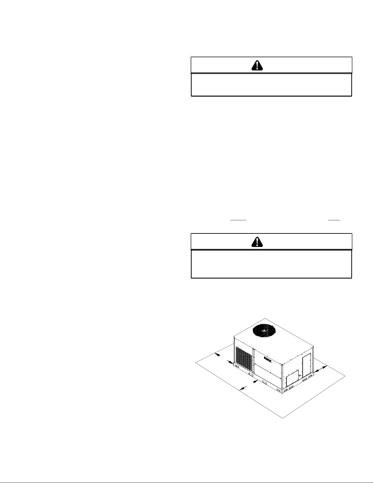
CLEARANCES
24”*
Min.
36”
Min.
Proper unit installation requires that the roof curb be firmly and
permanently attached to the roof structure. Check for adequate
fastening method prior to setting the unit on the curb.
Full perimeter roof curbs are available from the factory and are
UNIT CLEARANCES
*In situations that have multiple units, a 48” minimum clearance is
required between the condenser coils.
Adequate clearance around the unit should be k ept f or safety, ser-
4
Page 5
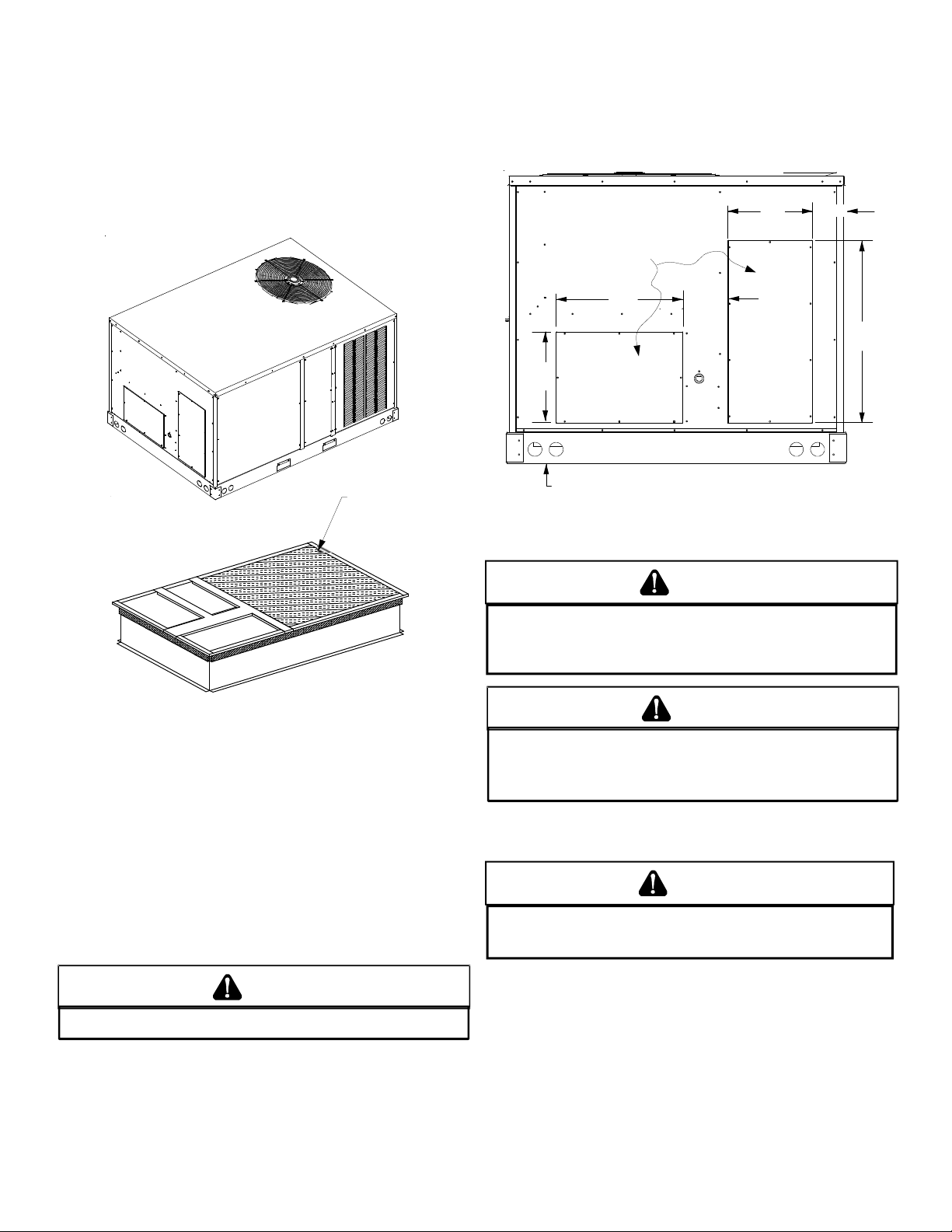
vice, maintenance, and proper unit operation. A total clearance
of 75” on the main control panel side of the unit is r ecommende d
to facilitate possible f an shaft, coil, and electric heat. A clearance
of 48” is recommended on all other sides of the unit to facilitate
possible compressor removal, to allow service access and to insure proper ventilation and condenser airflow. The unit must not
be installed beneath an y obs truction. The unit should be installe d
remote from all building exhausts to inhibit ingestion of exhaust
air into the unit fresh air intake.
Refer t o IOD-7006 included in the litera ture pack for inst alling horizontal duct covers.
Flexible duct connectors between the unit and ducts are recommended. Insulate and weatherproof all external ductwork and
joints as required and in accordance with local codes.
11 ” 4 7/8””
REMOVE
COVERS
17” 7 3/8”
INSULATED
PANELS
ROOF CURB INSTALLATION
ROOF CURB POST -INSTALLA TION CHECKS
After installation, check the top of the curb, duct connection fr ame
and duct flanges to make sure gasket has been applied properly.
Gasket should be firmly applied to the top of the curb perimeter,
duct flanges and any exposed duct connection frame. If gasket is
loose, re-apply using strong weather resistant adhesive.
PROTRUSION
Inspect curb to ensure that none of the utility services (electric)
routed through the curb protrude above the curb.
CAUTION
IF
PROTRUSIONS EXIST, DO NO ATTEMPT TO SET UNIT ON CURB
.
ROOF TOP DUCT CONNECTIONS
RETURN
12”
SUPPLY
6 3/16”
HORIZONTAL DISCHARGE DUCT CONNECTIONS
25”
RIGGING DET AILS
WARNING
O PREVENT PROPERTY DAMAGE, THE UNIT SHOULD REMAIN IN AN UPRIGHT
T
POSITION DURING ALL RIGGING AND MOVING OPERATIONS.
LIFTING AND MOVING WHEN A CRANE IS USED, PLACE THE UNIT IN AN
ADEQUATE CABLE SLING.
T
O FACILITATE
CAUTION
IF
UNITS ARE LIFTED TWO AT A TIME, THE FORK HOLES ON THE
CONDENSER END OF THE UNIT MUST NOT BE USED
LENGTH IS
IS RECOMMENDED
42” TO
PREVENT DAMAGE TO THE UNIT; HOWEVER
.
. M
INIMUM FORK
, 48”
Provisions for fork s have been include d in the unit base frame. No
other fork locations are approved.
WARNING
O PREVENT POSSIBLE EQUIPMENT DAMAGE, PROPERTY DAMAGE, PERSONAL
T
INJURY OR DEAT H, THE FOL LOWING BU LLET POINTS MUST BE OB SERVED
WHEN INSTALLING THE UNIT.
• Unit must be lifted by the four lifting holes located at the
base frame corners.
• Lifting cables should be att ached to the unit with shackles.
• The distance between the crane hook and the top of the
unit must not be less than 60”.
• Two spreader bars must span over the unit to prevent
Install all duct connections on the unit before placing the unit on
rooftop.
HORIZONTAL DISCHARGE
5
Page 6
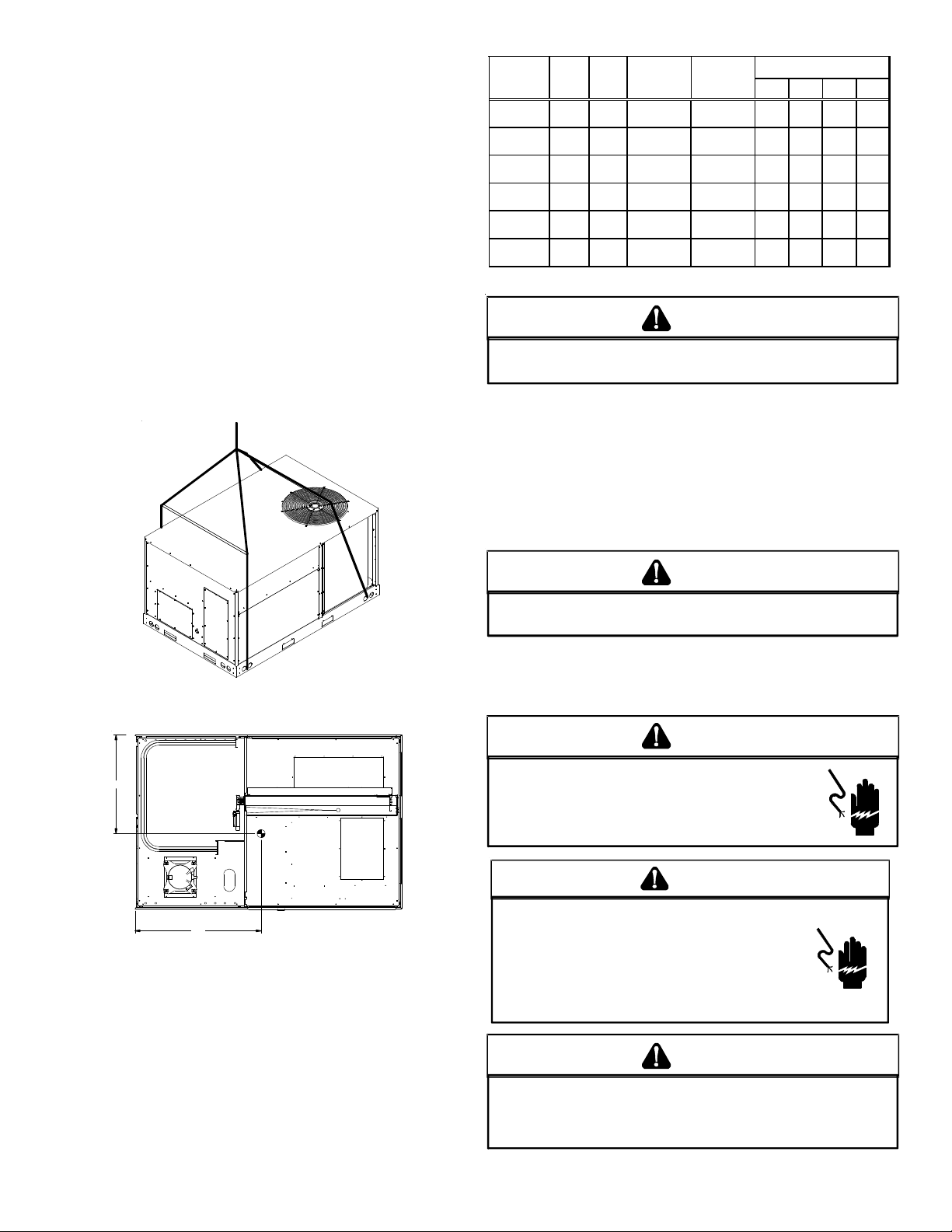
damage to the cabinet by the lift cables. Spreader bars
must be of sufficient length so that cables do not come in
contact with the unit during transport. Remove wood
struts mounted beneath unit base frame before setting
unit on roof curb. These struts are intended to protect
unit base frame from fork lift damage. Removal is
accomplished by extracting the sheet met al r etainer s and
pulling the struts through the base of the unit. Refer to
rigging label on the unit.
Important: If using bottom discharge with roof curb, ductwork
should be attached to the curb prior t o installing the unit. Ductwork
dimensions are shown in Roof Curb Installation Instructions.
Refer to the Roof Curb Installation Instructions for proper curb
installation. Curbing must be installed in compliance with the National Roofing Contractors Association Manual.
Lower unit carefully onto roof mounting curb. While rigging unit,
center of gravity will cause condenser end t o be lower than supply
air end.
A*
Model
DTC 036* 35 27 571 546 122 165 111 146
D T C 04 8 * 3 5 2 7 5 9 0 5 6 4 13 1 16 7 118 14 8
DT C060* 35 2 7 635 610 14 3 178 126 163
DTH 036* 34 28 581 556 130 175 105 146
D T H 04 8 * 3 4 2 8 6 0 0 5 7 4 13 1 18 1 111 15 1
DTH 060* 34 28 645 620 141 193 121 165
X (in) Y (in)
Shipping
Weight
(lbs)
Operating
Weight
(lbs)
Co rner Weights ( lbs )
ABCD
CAUTION
TO
PREVENT SEVERE DAMAGE TO THE BOTTOM OF THE UNIT, DO NOT
FORK LIFT UNIT AFTER WOOD STRUTS HAVE BEEN REMOVED
.
Bring condenser end of unit into alignment with the curb. With
condenser end of the unit resting on curb member and using curb
as a fulcrum, lower opposite end of the unit until entire unit is
seated on the curb. When a rectangular cantilever curb is used,
care should be taken to center the unit. Check for proper alignment and orientation of supply and return openings with duct.
To assist in determining rigging requirements, unit weights are
shown as follows:
A
Y
B
CONDENSER
COIL
COMPRESSOR
CG
X
RETURN
EVAPO RATOR COIL
CORNER & CENTER OF GRAVITY LOCATIONS
SUPPLY
C
D
RIGGING REMOVAL
CAUTION
TO
PREVENT DAMAGE TO THE UNIT, DO NOT ALLOW CRANE HOOKS
AND SPREADER BARS TO REST ON THE ROOF OF THE UNIT
.
Remove sprea der bars, lifting cable s and other rigging equipment.
ELECTRICAL WIRING
WARN ING
HIGH VOLTAGE!
ISCONNECT ALL POWER BEFORE SERVICING OR
D
INSTALLING THIS UNIT
BE PRESENT
DAMAGE, PERSONAL INJURY OR DEATH
. F
. M
AILURE TO DO SO MAY CAUSE PROPERTY
ULTIPLE POWER SOURCES MAY
.
WARNING
HIGH VOLTAGE!
T
O AVOID PERSONAL INJURY OR DEATH DUE TO
ELECTRICAL SHOCK, DO NOT TAMPER WITH FACTORY
WIRING
. THE
OF THESE UNITS ARE FACTORY-INSTALLED AND HAVE
BEEN THOROUGHLY TESTED PRIOR TO SHIPMENT
C
ONTACT YOUR LOCAL REPRESENTATIVE IF
ASSISTANCE IS REQUIRED
INTERNAL POWER AND CONTROL WIRING
.
.
CAUTION
TO
PREVENT DAMAGE TO THE WIRING, PROTECT WIRING FROM
SHARP EDGES
LOCAL CODES AND ORDINANCES
REMOVABLE ACCESS PANELS
6
. F
OLLOW NATIONAL ELECTRICAL CODE AND ALL
. DO
NOT ROUTE WIRES THROUGH
.
Page 7

CAUTION
C
ONDUIT AND FITTINGS MUST BE WEATHER-TIGHT TO PREVENT
WATER ENTRY INTO THE BUILDING
.
For unit protection, use a fuse or HACR circuit breaker that is in
excess of the circuit ampacity, but less than or equal to the maximum overcurrent protection device. DO NOT EXCEED THE MAXIMUM OVERCURRENT DEVICE SIZE SHOWN ON UNIT DATA PLATE.
All line voltage connections must be made through weatherproof
fittings. All exterior power supply and ground wiring must be in
approved weatherproof conduit.
The main power supply wiring to the unit and low voltage wiring
to accessory controls must be done in accordance with these instructions, the latest edition of the Na tional Electrical Code (ANSI/
NFP A 7 0), and all local codes and ordinances. All field wiring shall
conform with the temperature limitations for Type T wire (63°F/
35°C rise).
The unit is factory wired for the voltage shown on the unit’s data
plate. Refer to model nomenclature in Appendix B for voltage requirement for your unit.
NOTE: If supply voltage is 208V, lead on primary of transformer
must be moved from the 230V to the 208V tap. Refer to wiring
diagram on unit for details.
conductor in accordance with T able 250-95 of the National
Electrical Code. Do not use the ground lug for connecting
a neutral conductor.
• Remove plug in panel located at the condenser end of
unit and route conduit to control box. Remove plug in
control box and connect power wiring to the contactor
closest to the entrance. If Single Point kit is used, refer to
Installation Instructions supplied with kit.
MAIN POWER
LOW VOLTAGE
BLOCK
LOW VOLTAGE
ENTRANCE
POWER THRU
THE CURB
CONTROL BOX
Main power wiring should be sized f or the minimum wire ampacity
shown on the unit’s data plate. Size wires in accordance with the
ampacity tables in Article 310 of the National Electrical Code. If
long wires are required, it may be necessary to increase the wire
size to prevent e xce ssive volt age drop. Wires should be sized f or a
maximum of 3% voltage drop.
CAUTION
O AVOID PROPERTY DAMAGE OR PERSONAL INJURY DUE TO FIRE, USE
T
ONLY COPPER CONDUCTORS.
CAUTION
L
ABEL ALL WIRES PRIOR TO DISCONNECTION WHEN SERVICING
CONTROLS
DANGEROUS OPERATION
SERVICING
. W
IRING ERRORS CAN CAUSE IMPROPER AND
.
. V
ERIFY PROPER OPERATION AFTER
NOTE: A weather-tight disconnect switch, properly sized for the
unit total load, must be field or f actory inst alled. An e xternal field
supplied disconnect may be mounted on the exterior panel.
Ensure the data plate is not covered by the field-supplied
disconnect switch.
• Some disconnect switches are not fused. Protect the
power leads at the point of dis tribution in accordance with
the unit’s data plate.
• The unit must be electrically grounded in accordance with
local codes or , in the ab sence of local codes, with the lat est
edition of the National Electrical Code (ANSI-NFPA 70). A
ground lug is provided for this purpose. Size grounding
LOW VOLTAGE/THERMOSTAT CONNECTIONS
NOTE:
Some models may vary from illustration.
Models with electric heat are equipped
with a power block for field connections.
CONTROL BOX CONNECTIONS
GROUND
LUG
WARN ING
F
AILURE OF UNIT DUE TO OPERATION ON IMPROPER LINE VOLTAGE
OR WITH EXCESSIVE PHASE UNBALANCE CONSTITUTES PRODUCT
ABUSE AND WILL VOID YOUR WARRANTY AND MAY CAUSE SEVERE
DAMAGE TO THE UNIT ELECTRICAL COMPONENTS
.
Areas Without Convenience Outlet
It is recommended that an independent 115V power source be
brought to the vicinity of the roof top unit for portable lights and
tools used by the service mechanic.
NOTE: Refer to local codes for requirements. These outlets can
also be factory installed.
UNITS INSTALLED ON ROOF TOPS
Main power and low voltage wiring may enter the unit through
the condenser end or through the roof curb. Install conduit connectors at the desired en trance locations. External connector s must
be weatherproof. All holes in the unit base must be sealed (including those around conduit nuts) to prevent water leakage into
building. All required conduit and fittings ar e t o be field supplie d.
7
Page 8

Supply voltage to roof top unit mus t not vary by more than 10% of
the value indicated on the unit’s data plate. Pha se voltage unbalance must not exceed 2%. Contact your local power company for
correction of improper voltage or phase unbalance.
HIGH VOLTAGE ENTRANCE
(REMOVE PLUG)
NOTE: Field-supplied conduit may nee d t o be ins t alled depending
on unit/curb configuration. Use #18 AWG solid conductor wire
whenever connecting thermostat wire s to terminals on sub-ba se.
DO NOT use larger than #18 AWG wire. A transition to #18 AWG
wire may be required before entering thermostat sub-base.
NOTE: Refer to unit wiring diagrams for thermostat hookups.
* (6 Ton - 34 1/4”)
RETURN
SUPPLY
1:4
POWER THRU
THE CURB
12 3/8”
30 1/4”*
LOW VOLTAGE ENTRANCE
3.5 DIA.
4 1/2”
CIRCULATING AIR AND FILTERS
DUCTWORK
The supply duct from the unit through a wall may be inst alled without clearance. However, minimum unit clearances must be maintained (see “Clearance s” section). The supply duct should be provided with an access panel large enough to inspect the air chamber downstream of the heat exchanger. A cover should be tightly
attached to prevent air leaks.
Ductwork dimensions are shown in the roof curb installation
manual.
If desired, supply and return duct connections to the unit may be
made with flexible connections to reduce possible unit operating
sound transmission.
CONDENSA TE DRAIN CONNE CTION
CONDENSATE DRAIN CONNECTION
A 3/4” female NPT drain connection is supplied on the end of the
unit and bottom of the drain pan f or condensat e piping. An ext ernal trap must be installed for proper condensate drainage.
DRAIN
CONNECTION
47 1/2”
ELECTRICAL ENTRANCE AND THRU CURB
7 1/2”
LOW VOLTAGE CONTROL WIRING
1. A 24V thermostat must be installed for unit operation. It
may be purchased with the unit or field -supplied.
Thermostats may be progr ammable or electromechanical
as required.
2. Locate thermostat or remote sensor in the conditioned
space where it will sense average temperature. Do not
locate the device where it may be directly exposed to
supply air, sunlight or other sources of heat. Follow
installation instructions packaged with the thermostat.
3. Use #18 AWG wire for 24V control wiring runs not
exceeding 75 f eet. Use #16 A WG wire f or 24V control wiring
runs not exceeding 125 feet. Use #14 AWG wire for 24V
control wiring runs not exceeding 200 feet. Low voltage
wiring may be National Electrical Code (NEC) Class 2 wher e
permitted by local codes.
4. Route thermostat wires from sub-base terminals to the
unit. Control wiring should enter through the condenser
panel opening indicated in “Electrical Entrance” figure.
Connect thermostat and any accessory wiring to low
voltage terminal block TB1 in the main control box.
UNIT 2" MINIMUM
FLEXIBLE
TUBING-HOSE
OR PIPE
A POSITIVE LIQUID
SEAL IS REQUIRED
Drain Connection
3" MIN IMUM
Install condensate drain trap as shown. Use 3/4” drain line and
fittings or larger. Do not operate without trap.
HORIZONTAL DRAIN
Drainage of condensate directly on to the r oof ma y be accept able;
refer to local code. It is recommended that a small drip pad of
either stone, mortar, wood or metal be provided to prevent any
possible damage to the roof.
CLEANING
Due to the fact that drain pans in any air conditioning unit
will have some moisture in them, algae and fungus will
grow due to airborne bacteria and spores. Periodic cleaning is necessary to prevent this build-up from plugging the
drain.
8
Page 9

ST ARTUP, ADJUSTMENTS, AND CHECKS
WARN ING
HIGH VOLTAGE!
O AVOID PERSONAL INJURY OR DEATH DUE TO
T
ELECTRICAL SHOCK, B
THE BUILDING ELECTRICAL GROUND BY USE OF THE
GROUNDING TERMINAL PROVIDED OR OTHER
ACCEPTABLE MEANS
SERVICING OR INSTALLING THIS UNIT
OND THE FRAME OF THIS UNIT TO
. D
ISCONNECT ALL POWER BEFORE
.
PRE-STARTUP INSTRUCTIONS
CONTRACTOR RESPONSIBILITY
The installing contractor must be certain that:
• All supply and return air ductwork is in place, properly
sealed, and corresponds with installation instructions.
• All thermostats are mounted and wired in accordance
with installation instructions.
• All electric power, all gas, hot water or steam line
connections, and the condensate drain installation have
been made to each unit on the job. These main supply
lines must be functional and capable of operating all unit s
simultaneously.
• All filters are in place.
CAUTION
TO
PREVENT PROPERTY DAMAGE OR PERSONAL INJURY
START THE UNIT UNTIL ALL NECESSARY PRE-CHECKS AND TESTS
HAVE BEEN PERFORMED
.
, DO
NOT
Prior to the beginning of Startup, Adjustments, and Checks pr ocedures, the following steps should be completed in the building.
WARN ING
MOVING MACHINERY HAZARD!
O PREVENT POSSIBLE PERSONAL INJURY OR DEATH, DISCONNECT
T
POWER TO THE UNIT AND PADLOCK IN THE
SERVICNG FANS
.
“OFF”
POSITION BEFORE
HEATING STARTUP
On new installations, or if a major component has been replaced,
the operation of the unit must be checked.
Check unit operation as outlined in the following instructions. If
any sparking, odors, or unusual sounds are encountered, shut off
electrical power and recheck for wiring errors, or obstructions in
or near the blower motors. Duct cov er s must be removed before
operating unit.
The Startup, Adjustments, and Checks procedure provides a stepby-step sequence which, if follow ed, will assure the proper st artup
of the equipment in the minimum amount of time. Air balancing
of duct system is not considered part of this procedure. However,
it is an important phase of any air c onditioning sys tem st artup and
should be performed upon completion of the Startup, Adjustment s,
and Checks procedure. The St artup, Adjustment s, and Checks procedure at outside ambients below 55°F should be limit ed to a readiness check of the refrigera tion system with the requir ed final check
and calibration left to be completed when the outside ambient
rises above 55°F.
TEMPORARY HEATING OR COOLING
If the unit is to be used for tempor ary heating or cooling, a “Startup,
Adjustments, and Checks” must first be performed in accordance
with this manual. Failure to comply with this requir ement will void
the warranty. After the machines are used for temporary heating
or cooling, inspect the coils, fans, and motors for unacceptable
levels of construction dust and dirt and install new filters.
ROOF CURB INSTALLATION CHECK
Inspect the roof curb for correct installation. The unit and curb
assembly should be level. Inspect the flashing of the roof mounting curb to the roof, especially at the corners, for good workmanship. Also check for leaks around g a s kets. Note any deficiencies in
a separate report and for ward to the contractor.
OBSTRUCTIONS, FAN CLEARANCE AND WIRING
Remove any extraneous construction and shipping materials that
may be found during this procedure. Rotate all fans manually to
check for proper clearances and that they rotate freely. Check for
bolts and screws that may have jarred loose during shipment to
the job site. Retighten if necessary. Re-tighten all electrical connections.
FIELD DUCT CONNECTIONS
Verify that all duct connections are tight and that there is no air
bypass between supply and return.
FILTER SECTION CHECK
Remove filter section access panels and check that filter s are properly installed. Note airflow arrows on filter frames.
PRE-STARTUP PRECAUTIONS
It is important to your safety that the unit has been properly
grounded during installation. Check gr ound lug connection in main
control box for tightness prior to closing circuit breaker or disconnect switch. Verify that supply voltage on line side of disconnect
agrees with voltage on unit identification plate and is within the
utilization voltage rang e as indicat ed in Appendix B Electrical Data.
System Voltage - That nominal voltage value assigned to a circuit
or system for the purpose of designating its voltage class.
Nameplate Voltage - That voltage assigned to a piece of equipment for the purpose of designating its voltage class and for the
purpose of defining the minimum and maximum voltage at which
the equipment will operate.
Utilization Voltage - The voltag e of the line terminals of the equipment at which the equipment must give fully satisfactory performance. Once it is established that supply voltage will be maintained within the utilization range under all system conditions,
check and calculate if an unbalanced condition exists between
phases. Calculate percent voltage unbalance as follows:
9
Page 10

AIR FLOW ADJUSTMENTS
EEM MOTOR
Adjust the CFM for the unit by changing the position of the low
voltage leads on the motor terminal block. Green is for Fan Only.
Y ello w is for Cooling and Heat Pump Heating. R efer to Appendix A
for blower performance at each speed tap. NOTE: If more than
one lead is energized simultaneously, the motor will run at the
higher speed.
REFRIGERATION SYSTEM CHECKS
Ensure the hold-down bolts on the compressor are secur e and have
not vibrated loose during shipment. Check that vibration grommets have been installe d. Visually check all piping and clamps. The
entire refrigeration system has been factory charged and tested,
making it unnecessary to field charge. Factory charges are shown
on the unit nameplate.
START-UP PROCEDURE AND CHECKLIST
Begin with power turned off at all disconnects.
AIR CONDITIONING START-UP PROCEDURE
1. Turn thermostat system switch to “Cool,” and fan switch
to “Auto” and turn temperature setting as high as it will
go.
2. Inspect all registers and set them to the normal open
position.
3. Turn on the electrical supply at the disconnect.
4. Turn the fan switch to the “ON” position. The blower
should operate after a 7 second delay.
5. Turn the f an s witch t o “Auto” position. The blower should
stop after a 65 second delay.
6. Slowly lower the cooling temperatur e until the unit starts.
The compressor , blo wer and fan should now be oper ating.
Allow the unit to run 10 minutes, make sure cool air is
being supplied by the unit.
7. Turn the temperature setting to the highest position,
stopping the unit. The indoor blower will continue to run
for 65 seconds.
8. Turn the thermostat system switch to “OFF” and
disconnect all power when servicing the unit.
WARN ING
HIGH VOLTAGE!
ISCONNECT ALL POWER BEFORE SERVICING OR
D
INSTALLING THIS UNIT
BE PRESENT
DAMAGE, PERSONAL INJURY OR DEATH
. F
. M
AILURE TO DO SO MAY CAUSE PROPERTY
ULTIPLE POWER SOURCES MAY
.
HEAT PUMP START-UP PROCEDURE
9. Check the cooling mode for the heat pump in the same
manner as above. The reversing valve is energized when
the thermostat is placed in the cooling position. A clicking
sound should be noticeable from the reversing valve. By
lowering the temperature setting to call for cooling, the
contractor is energized. The compressor, blower and fan
should then be running. After the cooling mode is checke d
out, turn the thermostat system switch to “OFF”.
10. Turn the thermostat system switch to “HEAT” and fan
switch to “AUTO”.
11. Slowly raise the heating temperature setting. When the
heating first stage makes contact, stop raising the
temperature setting.. The compressor, blower and fan
should now be running with the reversing v alve in the deenergized (heating) position. After giving the unit time to
settle out, make sure the unit is supplying heated air.
12. If the outdoor ambien t is abov e 80°F, the unit may trip on
its high pressure cut out when on hea ting. The compressor
should stop. The heating cycle must be thoroughly
checked, so postpone the test to another day when
conditions are more suitable but-DO NOT FAIL TO TEST.
If the outdoor ambient is low and the unit operates
properly on the heating cycle, you ma y check the pressur e
cutout operation by blocking off the indoor re turn air until
the unit trips.
13. If unit operates properly in the heating cycle, raise the
temperature se tting until the hea ting second stag e make s
contact. Supplemental resistance heat, if installed should
now come on. Make sure it operates properly.
NOTE: If outdoor thermostats are installed the outdoor
ambient must be below the set poin t of these thermostats
for the heaters t o operate. It may be necessary to jumper
these thermostats to check heater operation if outdoor
ambient is mild.
14. For thermostats with emergency heat switch, return to
step 11. The emergency heat switch is located at the
bottom of the thermosta t. Move the swit ch to emergency
heat. The heat pump will stop, the blower will continue t o
run, all heaters will come on and the thermostat
emergency heat light will come on.
15. If checking the unit in the wintertime, when the outdoor
coil is cold enough to actuate the defro st con trol, observe
at least one defrost cycle to make sure the unit defrosts
completely.
FINAL SYSTEM CHECKS
16. Check to see if all supply and r eturn air grilles ar e adjuste d
and the air distribution system is balanced for the best
compromise between heating and cooling.
17. Check for air leaks in the ductwork. See Sections on Air
Flow Adjustments.
18. Make sure the unit is free of “rattles”, and the tubing in
the unit is free from excessive vibration. Also make sure
tubes or lines are not rubbing ag ainst e ach other or sheet
metal surfaces or edges. If so, correct the trouble.
19. Set the thermostat at the appropriate setting for cooling
and heating or automatic changeover for normal use.
10
Page 11

20. Be sure the Owner is instructed on the unit oper ation, filter ,
servicing, correct thermostat operation, etc.
REFRIGERATION PERFORMANCE CHECK
Check that compressor RLA corresponds to values shown in Appendix B. RLA draw can be much lower than values listed at low
load conditions and low ambient condensing temperatures. Values in Appendix B can slightly exceed at high load conditions and
high ambient condensing temperatures.
HEAT PUMP OPERATION
COOLING CYCLE
When the heat pump is in the cooling cycle, it operat es exactly as
a Summer Air Conditioner unit. In this mode, all the charts and
data for service that apply to summer air conditioning apply to
the heat pump. Most apply on the heating cy cle e xcept that “ condenser” becomes “evaporator”, “evaporator” becomes “condenser”, “cooling” becomes “heating”.
HEATING CYCLE
The heat pump operat es in the heating cycle by redirecting refrigerant flow through the r efriger ant circuit e xternal to the compre ssor . This is accomplishe d with through the re versing valv e. Hot discharge vapor from the compressor is directed to the indoor coil
(evaporator on the cooling cycle) where the heat is removed, and
the vapor condenses to liquid. It then goes thr ough the expansion
device to the outdoor coil (condenser on the cooling cycle) wher e
the liquid is evaporated, and the vapor goes to the compressor.
When the solenoid valve coil is operated either from heating to
cooling or vice versa, the piston in the reversing valve to the low
pressure (high pressure) reverse positions in the reversing valve.
The following figures show a schematic of a heat pump on the
cooling cycle and the heating cycle. In a ddition to a rever sing valve,
a heat pump is equipped with an expansion device and check v alve
for the indoor coil, and similar equipment for the outdoor coil. It
is also provided with a defrost control system.
The expansion devices are flowrator distributors and perform the
same function on the heating cycle as on the cooling cycle. The
flowrator distributors also act as check valves to allow for the reverse of refrigerant flow.
When the heat pump is on the heating cycle, the outdoor coil is
functioning as an evaporator. The temperature of the refrigerant
in the outdoor coil must be below the temperatur e of the outdoor
air in order to extract heat from the air. Thus, the greater the
difference in the outdoor temperature and the outdoor coil temperature, the gr ea t er the he a ting c ap acity of the he at pump. This
phenomenon is a characteristic of a heat pump. It is a good pr actice to provide supplementary heat f or all he a t pump inst allations
in areas where the temperature drops below 45° F. It is also a
good practice to provide sufficient supplementary heat to handle
the entire heating requiremen t should ther e be a c omponent f ailure of the heat pump, such as a compressor, or refrigerant leak,
etc.
Since the temperature of the r efrigeran t in the outdoor coil on the
heating cycle is generally below freezing point, frost forms on the
surfaces of the outdoor coil under certain weather conditions of
temperature and relative humidity. Therefore, it is necessary to
reverse the flow of the refrigerant to provide hot gas in the outdoor coil to melt the frost accumulation. This is accomplished by
reversing the heat pump to the cooling cycle. At the same time,
the outdoor fan stops to hasten the temperature rise of the outdoor coil and lessen the time required for defrosting. The indoor
blower continues to run and the supplemen t ary heat ers ar e energized.
DEFROST CONTROL
During operation the power to the circuit board is controlled by a
temperature sensor, which is clamped to a feeder tube entering
the outdoor coil. Defrost timing periods of 30,60 and 90 minutes
may be selected by connecting the circuit board jumper to 30, 60
and 90 respectively. Accumulation of time for the timing period
selected starts when the sensor closes (approximately 31° F), and
when the wall thermostat calls for heat. At the end of the timing
period, the unit’s defrost cycle will be initiated provided the sensor remains closed. When the sensor opens (appro ximately 75° F),
the defrost cycle is terminated and the timing period is reset. If
the defrost cycle is not terminated due to the sensor temperature, a ten minute override interrupts the unit’s defrost period.
11
Page 12

MAINTENANCE
WARN ING
HIGH VOLTAGE!
ISCONNECT ALL POWER BEFORE SERVICING OR
D
INSTALLING THIS UNIT
BE PRESENT
DAMAGE, PERSONAL INJURY OR DEATH
. F
. M
AILURE TO DO SO MAY CAUSE PROPERTY
ULTIPLE POWER SOURCES MAY
.
CABINET FINISH MAINTENANCE
Use a fine gra de automotiv e wax on the c abinet finish t o maintain
the finish’s original high luster. This is especially important in installations with extended periods of direct sunlight.
CLEAN OUTSIDE COIL (QUALIFIED SERVICER ONLY)
The coil with the outside air flowing over it should be inspected
annually and cleaned as frequently a s necessary to keep the finne d
areas free of lint, hair and debris.
WARN ING
TO
PREVENT PERSONAL INJURY OR DEATH DUE TO IMPROPER
INSTALLATION, ADJUSTMENT, ALTERATION, SERVICE OR
MAINTENANCE, REFER TO THIS MANUAL
ASSISTANCE OR INFORMATION, CONSULT A QUALIFIED INSTALLER
SERVICE AGENCY OR THE GAS SUPPLIER
. FOR
.
ADDITIONAL
,
CAUTION
S
HEET METAL PARTS, SCREWS, CLIPS AND SIMILAR ITEMS INHERENTLY
HAVE SHARP EDGES, AND IT IS NECESSARY THAT THE INSTALLER AND
SERVICE PERSONNEL EXERCISE CAUTION
.
The Self Contained Packaged Air Conditioner and He at Pump should
operate for man y year s without exce ssive service calls if the unit is
installed properly. However it is recommended that the homeowner inspect the unit before a sea sonal start up. The coils should
be free of debris so adequate airflow is achieved. The return and
supply registers should be free of any obstructions. The filters
should be cleaned or replaced. These few steps will help to keep
the product up time to a maximum. The Service section that follows should help in identifying problems if the unit does not oper ate properly.
FILTERS
CAUTION
T
O PREVENT PRO PERTY DAMAG E DUE TO FIRE AND LOSS O F
EQUIPMENT EFFICIENCY OR EQUIPMENT DAMAGE DUE TO DUST AND LINT
BUILD UP ON INTERNAL PARTS, NEVER OPERATE UNIT WITHOUT AN AIR
FILTER INSTALLED IN THE RETURN AIR SYSTEM.
Every application may require a different frequency of replacement of dirty filters. Filters must be replaced at least every three
(3) months during operating seasons.
Dirty filters are the most common cause of inadequat e he a ting or
cooling performance. Filter inspection should be made at least
every two months; more often if necessary because of local conditions and usage.
Dirty throwaway filters should be discarded and replaced with a
new, clean filter.
Disposable return air filters are supplied with this unit. See the
unit Specification Sheet or Technical Manual for the correct size
and part number. To remove the filters, remove the filter access
panel on return side of the unit.
LUBRICATION
The fan shaft bearings , the 1 to 2 HP supply fan motors, the condenser fan motors and compressors are permanently lubricated.
FUNCTIONAL PARTS
Refer to the unit Parts Catalog for a list of functional parts. Parts
are available from your distributor.
TROUBLESHOOTING
THE FOLLOWING INFORMATION IS FOR USE BY QUALIFIED SERVICE AGENCY ONLY: OTHERS SHOULD NOT AT TEMPT TO SERVICE
THIS EQUIPMENT.
Common Causes of Unsatisfactory Operation of Heat Pump on the
Heating Cycle.
INADEQUATE AIR VOLUME THROUGH INDOOR COIL
When a heat pump is in the heating cycle, the indoor coil is functioning as a condenser. The return air filter must always be clean,
and sufficient air volume must pass thr ough the indoor coil to prevent excessive discharge pressure, and high pressure cut out.
OUTSIDE AIR INTO RETURN DUCT
Do not introduce cold outside air into the return duct of a heat
pump installation. For units with 2-speed motor s, do not allow air
entering the indoor coil to drop below 65° F. Air below this temperature will cause low discharg e pr essur e, thus low suction pr e ssure, and excessive de frost cycling r esulting in lo w heating output.
It may also cause false defrosting.
UNDERCHARGE
An undercharged heat pump on the heating cycle will cause low
discharge pressure resulting in low suction pressure and frost accumulation on the outdoor coil.
POOR “TERMINATING” SENSOR CONTACT
The unit’s defrost terminating sensor must make good thermal
contact with the outdoor coil tubing. Poor cont act may not terminate the unit’s defrost cycle quickly enough to prevent the unit
from cutting out on high discharge pressure.
MALFUNCTIONING REVERSING VALVE - THIS MAY BE DUE TO:
1. Solenoid not energized - In order to determine if the
solenoid is energized, touch the nut that holds the solenoid
cover in place with a screwdriver. If the nut magnetically
holds the screwdriver, the solenoid is energized and the
unit is in the cooling cycle.
12
Page 13

2. No voltage at unit’s solenoid - Check unit voltage. If no
voltage, check wiring circuit.
3. Valve will not shift:
a. Undercharged - check for leaks;
b. Valve Body Damaged - Replace valve;
c. Unit Properly Charg e d - If it is on the hea ting cycle, r aise
the discharge pressur e by re stricting airflow thr ough the
indoor coil. If the valve does not shift, tap it lightly on
both ends with a screwdriver handle. DO NOT TAP THE
VALVE BODY. If the unit is on the cooling cycle, raise the
discharge pressure by restricting airflow through the
outdoor coil. If the valve does not shift after the above
attempts, cut the unit off and wait until the discharge
and suction pressure equalize, and repea t above st eps. If
the valve does not shift, replace it.
13
Page 14

APPENDIX A BLOWER PERFORMANCE TABLES
L
DIRECT DRIVE
STANDARD DOWN SHOT AND HORIZONTAL
STANDARD DTC/DTH036
SPEED
TAP
T1
T2
T3
T4
T5
Notes:
Table represent dry coil without filter, to compensate f o r f ilter add 0.08" to measured E.S.P.. S CF M
correction f or wet coil = 4%. 5 Ton models are shipped from the f actory with speed tap set on T4.
EXTERNAL
STATIC
PRESSURE (E SP )
0.1 966 0.5 108 657 T1 0.1 1018 0.47 101 615
0.2 850 0.52 115 710 0.2 969 0.49 109 653
0.3 773 0.55 122 763 0.3 881 0.53 117 712
0.4 678 0.59 130 819 0.4 818 0.55 125 768
0.5 593 0.62 141 875 0.5 732 0.59 135 833
0.6 0.6 658 0.63 142 890
0.7 0.7 616 0.65 148 938
0.8 0.8
0.9 0.9
0.1 1057 0.6 134 693 T2 0.1 1128 0.56 126 645
0.2 956 0.62 140 740 0.2 1070 0.59 132 692
0.3 868 0.66 144 787 0.3 994 0.62 138 727
0.4 788 0.69 156 839 0.4 915 0.66 149 791
0.5 700 0.73 166 898 0.5 839 0.69 156 838
0.6 618 0.76 174 946 0.6 776 0.73 169 909
0.7 0.7 698 0.77 179 963
0.8 0.8 649 0.8 183 1003
0.9 0.9
0.1 1234 0.86 199 784 T3 0.1 1293 0.81 186 733
0.2 1146 0.89 206 822 0.2 1252 0.84 193 765
0.3 1068 0.92 213 863 0.3 1198 0.87 204 803
0.4 977 0.96 221 910 0.4 1130 0.91 212 844
0.5 911 1 232 949 0.5 1075 0.94 218 886
0.6 842 1.04 245 998 0.6 1015 0.98 230 930
0.7 776 1.08 253 1031 0.7 941 1.02 242 984
0.8 703 1.11 263 1082 0.8 870 1.08 253 1045
0.9 682 1.13 266 1107 0.9 817 1.11 262 1080
0.1 1363 1.03 242 822 0.1 1404 0.99 232 789
0.2 1253 1.09 251 874 0.2 1367 1.02 240 817
0.3 1176 1.12 260 910 0.3 1334 1.05 244 845
0.4 1110 1.15 270 940 0.4 1265 1.09 257 882
0.5 1034 1.19 279 981 0.5 1207 1.13 265 922
0.6 966 1.23 290 1028 0.6 1153 1.17 272 958
0.7 899 1.27 301 1074 0.7 1090 1.21 283 1005
0.8 836 1.33 312 1117 0.8 1029 1.25 299 1052
0.9 778 1.35 319 1146 0.9 947 1.31 312 1111
0.1 1413 1.14 268 849 T5 0.1 1457 1.08 254 805
0.2 1299 1.18 275 899 0.2 1413 1.12 266 839
0.3 1233 1.23 259 933 0.3 1359 1.16 273 870
0.4 1166 1.26 296 963 0.4 1307 1.2 285 911
0.5 1096 1.3 307 1000 0.5 1253 1.23 291 940
0.6 1026 1.34 318 1040 0.6 1197 1.28 304 978
0.7 960 1.39 330 1052 0.7 1138 1.31 310 1017
0.8 889 1.44 340 1132 0.8 1082 1.36 322 1059
0.9 835 1.47 347 1169 0.9 1029 1.41 335 1105
STANDARD
CFM
AMPS WATTS RPM
SPEED
TAP
T4
EXTERNAL
STATIC
PRESS URE (ESP)
DOWNSHOT HORIZONTA
STAN DARD
CFM
AMPS WATTS RPM
14
Page 15

APPENDIX A BLOWER PERFORMANCE TABLES
DIRECT DRIVE
STANDARD HORIZONTAL
STANDARD DTC/DTH048
DOWNSHOT HORIZONTAL
EXTERNAL
SPEED
TAP
T1 32%
T2 39%
T3 55%
T4 63%
T5
66.5%
Notes:
Table represent dry coil without filter, to compensat e for filter add 0.08" to measured E.S .P.. SC F M
correction f or wet coil = 4%. 5 Ton models are ship ped f r om th e f actory with speed tap set on T4.
STATIC
PRESSURE (ESP)
in w.c.
0.1 1286 0.82 187 667
0.2 1205 0.86 198 704 0.2 1286 0.8 186 657
0.3 1139 0.8 205 731 0.3 1 211 0.84 198 698
0.4 1052 0.92 212 764 0.4 1144 0.88 204 730
0.5 982 0.95 215 790 0.5 1068 0.92 214 768
0.6 911 0.97 224 814 0.6 996 0.95 222 798
0.7 840 1 230 837 0.7 923 0.98 229 829
0.8 779 1.02 235 855 0.8 839 1.01 235 857
0.9 717 1.04 242 879 0.9 777 1.04 242 881
0.1 1470 1.09 251 726
0.2 1399 1.12 260 758 0.2 1482 1.05 246 710
0.3 1315 1.16 271 790 0.3 1412 1.09 256 745
0.4 1253 1.19 281 814 0.4 1352 1.13 263 774
0.5 1180 1.22 287 842 0.5 1286 1.17 272 806
0.6 1110 1.26 292 867 0.6 1216 1.19 281 839
0.7 1042 1.29 300 891 0.7 1147 1.24 289 868
0.8 973 1.32 308 914 0.8 1077 1.27 299 892
0.9 916 1.34 314 933 0.9 1002 1.31 309 922
0.1 1747 1.75 413 855
0.2 1668 1.8 414 884 0.2 1 762 1.65 392 809
0.3 1609 1.84 436 908 0.3 1697 1.69 399 835
0.4 1557 1.88 442 931 0.4 1651 1.74 416 863
0.5 1489 1.92 453 957 0.5 1598 1.79 423 892
0.6 1419 1.97 476 984 0.6 1533 1.85 438 922
0.7 1377 2 472 1002 0.7 1464 1.89 447 951
0.8 1311 2.03 479 1022 0.8 1417 1.94 458 975
0.9 1256 2.07 488 1044 0.9 1361 1.97 475 999
0.1 1879 2.11 504 908
0.2 1799 2.16 512 935 0.2 1888 1.99 471 853
0.3 1730 2.2 525 955 0.3 1 847 2.04 491 876
0.4 1677 2.26 539 981 0.4 1790 2.09 502 906
0.5 1630 2.31 547 1006 0.5 1742 2.14 509 928
0.6 1558 2.35 557 1032 0.6 1682 2.19 537 957
0.7 1508 2.38 553 1049 0.7 1620 2.26 5337 987
0.8 1443 2.43 588 1072 0.8 1576 2.28 547 1010
0.9 1389 2.48 585 1091 0.9 1521 2.33 556 1034
0.1 1903 2.28 542 931
0.2 1838 2.31 561 952 0.2 1946 2.16 511 876
0.3 1785 2.38 571 977 0.3 1893 2.15 518 896
0.4 1723 2.41 574 1002 0.4 1865 2.28 536 923
0.5 1666 2.46 585 1020 0.5 1795 2.26 548 351
0.6 1612 2.51 596 1048 0.6 1741 2.39 555 376
0.7 1547 2.56 611 1067 0.7 1681 2.38 572 999
0.8 1505 2.59 607 1083 0.8 1630 2.47 597 1023
0.9 1445 2.63 613 1109 0.9 1576 2.47 595 1046
STANDARD
CFM
AMPS WATTS RPM
SPEED
TAP
T1 32%
T2 39%
T3 55%
T4 63%
T5
EXTERNAL
STATIC
PRESSURE (ESP)
in w.c.
STANDARD
CFM
0.1 1346 0.77 176 622
0.1 1534 1.01 234 681
0.1 1515 1.61 382 787
0.1 1941 1.96 464 834
0.1 1994 2.09 497 845
AMPS WATTS RPM
15
Page 16

APPENDIX A BLOWER PERFORMANCE TABLES
DIRECT DRIVE
STANDARD DTC/DTH060 DOWN SHOT
SPEED
TAP
T1
T2
T3
T4
T5
NOTES:
Tables represent dry coil without filter, to compensate for filter add 0. 08 " to measured E.S.P. SCFM correction for wet coil = 4
%. 5 Ton models are shipped from the factory wit h speed tap set on T4.
EXTERNAL STATIC
PRESSURE (ESP)
in w.c.
0.10 1334 1.65 180 627
0.20 1286 1.75 192 665
0.30 1212 1.83 202 715
0.40 1144 1.94 216 759
0.50 1077 1.99 222 792
0.60 1039 2.10 238 830
0.70 953 2.17 248 874
0.80 904 2.27 258 913
0.90 825 2.30 266 940
0.10 1512 2.12 240 682
0.20 1469 2.24 254 720
0.30 1397 2.31 264 759
0.40 1333 2.44 282 803
0.50 1285 2.54 296 836
0.60 1221 2.59 304 874
0.70 1173 2.72 322 913
0.80 1118 2.77 328 946
0.90 1049 2.90 344 984
0.10 2053 4.27 540 869
0.20 2014 4.39 558 896
0.30 1999 4.60 576 929
0.40 1947 4.68 588 957
0.50 1897 4.79 608 989
0.60 1857 4.87 620 1012
0.70 1763 4.99 640 1050
0.80 1741 5.06 650 1072
0.90 1669 5.19 668 1105
0.10 2137 4.95 634 913
0.20 2093 5.07 652 940
0.30 2095 5.19 670 962
0.40 2026 5.28 682 990
0.50 1980 5.40 698 1018
0.60 1961 5.49 720 1039
0.70 1914 5.58 732 1072
0.80 1845 5.70 742 1100
0.90 1766 5.69 740 1127
0.10 2299 5.70 742 942
0.20 2233 5.80 748 969
0.30 2217 5.90 768 990
0.40 2157 6.07 786 1018
0.50 2131 6.12 804 1045
0.60 2060 6.21 816 1073
0.70 2015 6.30 820 1095
0.80 1940 6.27 816 1111
0.90 1862 6.13 790 1128
STANDARD
CFM
16
AMPS WATTS RPM
Page 17

APPENDIX A BLOWER PERFORMANCE TABLES
/
DIRECT DRIVE
STANDARD DTC/DTH060 HORIZONTAL
SPEED
TAP
T1
T2
T3
T4
T5
NOTES:
Tables represent dry coil without filter, to compensate for filter add 0.08" to measured E.S.P. SCFM correction for wet coil = 4
%.
5 Ton models are shipped from the factory with speed tap set on T4.
EXTERNAL STATIC
PRESSURE (ESP)
in w.c.
0.10 1355 1.57 174 599
0.20 1281 1.66 182 651
0.30 1235 1.76 196 693
0.40 1168 1.81 202 726
0.50 1118 1.94 218 775
0.60 1049 2.03 232 819
0.70 982 2.10 240 858
0.80 922 2.14 246 885
0.90 871 2.25 260 927
0.10 1544 2.04 234 660
0.20 1490 2.17 250 704
0.30 1427 2.25 260 742
0.40 1370 2.35 276 781
0.50 1319 2.42 282 809
0.60 1274 2.52 296 849
0.70 1210 2.62 316 891
0.80 1137 2.73 326 935
0.90 1106 2.77 336 957
0.10 2099 4.13 516 825
0.20 2068 4.25 536 852
0.30 2029 4.37 552 885
0.40 1971 4.48 568 913
0.50 1911 4.61 586 950
0.60 1876 4.73 604 973
0.70 1821 4.86 622 1012
0.80 1792 4.91 630 1028
0.90 1740 5.03 648 1067
0.10 2233 4.76 608 863
0.20 2168 4.91 628 896
0.30 2125 5.02 640 924
0.40 2070 5.14 660 951
0.50 2050 5.27 678 979
0.60 1980 5.41 696 1012
0.70 1954 5.47 704 1034
0.80 1893 5.60 724 1067
0.90 1852 5.70 736 1089
0.10 2322 5.44 710 904
0.20 2294 5.55 726 934
0.30 2254 5.68 742 958
0.40 2201 5.80 766 990
0.50 2147 5.93 782 1017
0.60 2117 6.01 788 1039
0.70 2081 6.12 808 1060
0.80 2017 6.22 822 1094
0.90 1932 6.10 804 1111
STANDARD
CFM
17
AMPS WATTS RPM
Page 18

APPENDIX B ELECTRICAL DATA
MODELS
3 TON 208/230-60-1 187 253 1 14.1 77 1 1/4 1.4 DD STD STATIC 1/2 3.9
4 TON 208/230-60-1 187 253 1 19.9 109 1 1/4 1.4 DD STD STATIC 1 6.9
5 TON 208/230-60-1 187 253 1 25.0 134 1 1/3 2.0 DD STD STATIC 1 6.9
VOLTAGE
(NAM EPLATE)
VOLTAGE
LIMITATION
MIN MAX QTY RLA LRA QTY HP RLA HP FLA
COMPR ESSOR
OUTDOOR
FAN MOTOR
INDOOR MOTOR
APPLICATION
INDOOR FAN
MOTOR
MINIMUM AIR F LOW FOR ELECTRIC HEAT
UNIT
3 TON
HEATER KIT
MODEL N UMBE R
EHK*-10 1250
EHK*-15 1250
MIN I MUM CFM
EHK*-10 1300
4 TON
EHK*-15 1400
EHK*-18 1400
EHK*-10 1700
5 TON
EHK*-15 1700
EHK*-20 1800
AT TENTION INSTALLING PERSONNEL
Use only the heater kit specified for each model as dictated by the table above.
18
Page 19

APPENDIX C UNIT DIMENSIONS
47 1/2”
38 13/16”*
74 1/16”
5 Ton “T” model
73 1/4”
48 3/16”
12”
6 1/4”
17” 7 3/8”
SUPPLY
HORIZONTAL DISCHARGE
11”
RETURN
4 7/8”
25”
19 7/16”
RETURN
5 7/8”
SUPPLY
8 3/16”
DRAIN
THRU CURB
LOCATION
27 3/8”
47 1/2”
BOTTOM VIEW OF UNIT
VERTICAL DISCHARGE
EMBOSS
FOR
THRU THE
BASE
UTILITIES
4 1/2”
7 1/2”
19
Page 20

WIRING DIAGRAMS
DTC0[36-60]XXX1DXXX
NOTE 3
RD
BK
3
2
1
C
BL
208
240
TR
24V
BL
PK
BL
BL
L2
T2
RD
RD
BK
BK
YL
L1
T1
C
YL/PK
BK
RD
BR
RD
YL
WH
GR
TB1
H
1
OR
BR
YL
WH
PU
5
3
4
1
2
EM
GLC
N
BL
L1
C
T1
C
BK
RD
SUPPLY VOLTAGE
208-240/1/60
R
COMP
5
SEE NOTE 2
GR
C
T2
RCCF
PU
C
F
L2
S
C
RCCF
HIGH VOLTAGE!
DISCONNECT ALL POWER BEFORE SERVICING OR INSTALLING THIS
UNIT. MULTIPLE POWER SOURCES MAY BE PRESENT . FAILURE TO
DO SO MAY CAUSE PROPERTY DAMAGE, PERSONAL INJURY OR DEATH.
EM
N
H
F
CM
L
G
3
208-240V
NOTE 3
2
1
TR
24V
SEE NOTE #2
1
2
3 C
EM
4
5
C
PLF2
89
7
5
6
4
3
1
2
PLF
4
5
6
TB1
LPS
HPS
WH
6
9
3
5
2
8
BR
1
4
7
GR
WH
BL
BL
PLF 1
RD
BK
YL
PU
CM
BK
BR
T3
COMP
T1
T2
COMPONENT LEGEND
C
CONTACTOR
CM
CONDENSER MOTOR
COMP
COMPRESSOR
EM
EVAPORATOR MOTOR
GND
EQUPIMENT GROUND
LVJB
LOW VOLTAGE JUNCTION BOX
PLF
FEMALE PLUG / CONNECTOR
RCCF
RUN CAPACITOR FOR
COMPRESSOR AND FAN
TB1
TERMINAL BLOCK (24V SIGNAL)
TR
TRANSFORMER
NOTES:
1. REPLACEMENT WIRE MUST BE SAME SIZE AND
TYPE INSULATION AS ORIGINAL (AT LEAST 105C)
USE COPPER CONDUCTOR ONLY.
2. TO CHANGE EVAPORATOR MOTOR SPEED MOVE
WHITE AND YELLOW LEADS FROM "3" AND "4" TO
"4" AND "5". IF BOTH LEADS ARE ENERGIZED, THE
HIGHER SPEED SETTING IS USED.
3. FOR 208 VOLT TRANSFORMER OPERATION MOVE
BLACK WIRE FROM TERMINAL 3 TO TERMINAL 2
ON TRANSFORMER.
4. USE COPPER CONDUCTORS ONLY
++
USE N.E.C. CLASS 2 WIRE.
5. ECONOMIZER PLUG LOCATED IN RETURN AIR
COMPARTMENT. REMOVE MALE PLUG AND ATTACH
FEMALE PLUG TO ECONOMIZER ACCESSORY.
SEE UNIT RATING PLATE FOR TYPE AND SIZE
OF OVER CURRENT PROTECTION
JUNCTION
TERMINAL
INTERNAL TO
INTEGRATED CONTROL
PLUG CONNECTION
SWITCH (PRESS.)
OVERCURRENT
PROT. DEVICE
EQUIPMENT GROUND
FIELD GROUND
FIELD SPLICE
SWITCH (TEMP)
IGNITER
YL
YL/PK
NOTE 5
GCY1
Y2
W1
W1
R
W2
R
W2
O
O
S2
S2
S1
S1
THERMOSTAT
TB1
GCY1
++
208-240/1/60 0140L02910-B
RD
RD
BK
BK
NOTE 4
GND
RD
GR
PLF 2
36
2
PU
5
4
1
BL
YL
LVJB
YL
PU
RD
GR
WH
BR
BL
OR
RD
PK
TB1
CONTROL BOX
HPS
SMOKE/FIRE DETECTOR
LPS
REPLACES JUMPER
FACTORY WIRING
LINE VOLTAGE
LOW VOLTAGE
OPTIONAL HIGH VOLTAGE
OPTIONAL LOW VOLTAGE
FIEL
HIGH VOLTAGE
LOW VOLTAGE
W
BK BLACK
BL BLUE
BR BROWN
GR GREEN
OR ORANGE
PK PINK
PU PURPLE
RD RED
WH WHITE
YL YELLOW
BL/PK BLUE WITH PINK STRIP
YL/PK YELLOW WITH PINK STRIP
THERMOSTAT
FIELD WIRING
NO
ECONOMIZER
W
G
R
Y1
Y2
Y2
C
O
TB1
ITH ECONOMIZER OPTION
W
W
G
R
Y1
Y2
C
O
TB1
2 STA
W
G
R
Y1
Y2
C
O
TB1
OR
9
8
7
BL/PK
D WIRING
IRE CODE
WH
GR
RD
YL
BL
OR
WH
GR
RD
YL
BL
OR
GE COOLING
WH
GR
RD
YL
PK
BL
OR
NOTE 5
Y1
Y2
R
G
W1
W2
C
O
S2
S1
++
STAT
W
G
R
Y
C
O
STAT
STAT
2
0
8
2
4
0
/
1
/
6
0
T
H
E
R
M
O
S
T
A
T
++
W
G
R
Y
C
O
W
G
R
Y1
Y2
C
O
20
Page 21

WIRING DIAGRAMS
DTH0[36-60]XXX1DXXX
SEE
NOTE 7
WH
YL/PK
S
P
L
YL/PK
YL
YL
YL
WH
GR
TB1
1
5
BR
OR
YL
WH
PU
4
3
5
1
2
EM
C
N
L
G
BL
BK
RD
L1
C
T1
C
SEE
HIGH VOLTAGE!
DISCONNECT ALL POWER BEFORE SERVICING OR INSTALLING THIS
UNIT. MULTIPLE POWER SOURCES MAY BE PRESENT . FAILURE TO
DO SO MAY CAUSE PROPERTY DAMAGE, PERSONAL INJURY OR DEATH.
NOTE 7
R
HVDR
DF1
SEE NOTE 2
GR
SUPPLY VOLTAGE
R
COMP
S
H
CHS
BR
C
C
R
CCR
LVDR
D2
DFT
208-240/1/60
T2
C
RCCF
F
SEE
NOTE 6
BL
PU
DC
C
CNT
0
OR
0
0-RV
BK
C-RV
W
Y
Y
PU
PS2
R-PS1
R-DFT
RD
PU
BK
RD
RD
BK
DFT
BK
H
RCCF
BR
RD
WH
C
F
RD
1
RVC
L2
C
DF2
DF1
HVDR
CM
CH
N
EM
G
R
RVC
LPS
P
P
4
L
L
F
F
5
1
1
6
L
208-240V
N
O
S
E
3
E
E
T
2
24V
C-RV
Y
HPS
1
TR
R-DFT
DC
R-PS1
1
2
3
4
5
DFT
DFT
PS2
SEE NOTE 2
C
EM
87
9
5
4
6
3
2
1
C
C
N
T
C
3
O-RV
R
O
W
PLF2
SEE NOTE 5
GCY1W1
W2
W2
R
R
O
O
S2
S2
S1
S1
THERMOSTAT
GCY1W1
Y2
++
BK
RD
3
1
2
C
PK
BL
240
208
TR
24V
BL
BL
BL
BL
RD
PU
PU
WH
WH
PLF 1
3
6
9
8
2
5
4
BR
7
BL
BK
PU
BR
YL
CM
COMPONENT LEGEND
CONTACTOR
C
COMPRESSOR CONTACTOR RELAY
CCR
CRANKCASE HEATER
CH
CRANKCASE HEATER SWITCH
CHS
CONDENSER MOTOR
CM
COMPRESSOR
COMP
DEFROST CONTROL
DC
DEFROST THERMOSTAT
DFT
ECONOMIZER
ECON
EVAPORATOR MOTOR
EM
EQUIPMENT GROUND
GND
HIGH PRESSURE SWITCH
HPS
HIGH VOLTAGE DEFROST RELAY
HVDR
LOW PRESSURE SWITCH
LPS
LOW VOLTAGE DEFROST RELAY
LVDR
LOW VOLTAGE JUNCTION BOX
LVJB
FEMALE PLUG / CONNECTOR
PLF
REVERSING VALVE COIL
RVC
RUN CAPACITOR FOR
RCCF
COMPRESSOR AND FAN
TERMINAL BLOCK (24V SIGNAL)
TB1
TRANSFORMER
TR
NOTES:
1. REPLACEMENT WIRE MUST BE SAME SIZE AND
TYPE INSULATION AS ORIGINAL (AT LEAST
105C) USE COPPER CONDUCTOR ONLY.
2. TO CHANGE EVAPORATOR MOTOR SPEED MOVE
WHITE AND YELLOW LEADS FROM "3" AND "4" TO
"4" AND "5". IF BOTH LEADS ARE ENERGIZED, THE
HIGHER SPEED SETTING IS USED.
3. FOR 208 VOLT TRANSFORMER OPERATION MOVE
BLACK WIRE FROM TERMINAL 3 TO TERMINAL 2
ON TRANSFORMER.
4. USE COPPER CONDUCTORS ONLY
USE N.E.C. CLASS 2 WIRE
++
5. ECONOMIZER PLUG LOCATED IN THE RETURN
AIR COMPARTMENT. REMOVE MALE PLUG AND
ATTACH FEMALE PLUG TO ECONOMIZER
ACCESSORY.
6. CRANKCASE HEATER AND CRANKCASE HEATER
SWITCH FACTORY EQUIPPED WHEN REQUIRED.
7. DOUBLE POLE CONTACTOR SHOWN. SINGLE POLE
CONTACTOR COULD BE FACTORY EQUIPPED AS AN
ALTERNATE CONFIGURATION.
SEE UNIT RATING PLATE FOR TYPE AND SIZE
OF OVER CURRENT PROTECTION
JUNCTION
TERMINAL
INTERNAL TO
INTEGRATED CONTROL
PLUG CONNECTION
SWITCH (PRESS.)
OVERCURRENT
PROT. DEVICE
2
BL
T2
RD
BK
T1
BK
PU
YL
RD
BK
T3
T1
COMP
EQUIPMENT GROUND
FIELD GROUND
FIELD SPLICE
SWITCH (TEMP)
IGNITER
/
1
0
2
/
4
-
8
0
RD
RD
L2
C
L1
BK
YL
PU
RD
GR
GR
WH
WH
WH
BR
OR
OR
BL
BL
BL
RD
RD
BR
PK
PU
YL
BL/PK
T2
HPS
9
7
-
2
0
0
0
4
L
1
0
0
6
BK
K
B
SEE NOTE 4
GND
OR
RD
GR
PU
YL
PLF 2
9
36
2
8
5
7
4
YL
1
BL
LVJB
TB1
BK
BL/PK
BK
CH
GR
WIRE CODE
BK BLACK
BL BLUE
BR BROWN
GR GREEN
OR ORANGE
PK PINK
RD RED
PU PURPLE
YL YELLOW
WH WHITE
BL/PK BLUE WITH PINK STRIP
YL/PK YELLOW WITH PINK STRIP
THERMOSTAT
FIELD WIRING
N
O ECONOMIZER
W
G
R
Y1
Y2
Y2
C
O
TB1
WITH ECONOMIZER OPTION
W
G
R
Y1
Y2
Y2
C
O
TB1
2 STAGE COOLING
W
G
R
Y1
Y2
C
O
TB1
B
NOTE 5
Y1
Y2
R
G
W1
W2
O
C
S2
S1
CONTROL
BOX
REPLACE
JUMPER WITH
SMOKE/FIRE
DETECTOR
SEE
NOTE 6
CTORY WIRING
FA
LINE VOLTAGE
LOW VOLTAGE
OPTIONAL
HIGH VOLTAGE
OPTIONAL
LOW VOLTAGE
FIELD WIRING
HIGH VOLTAGE
LOW VOLTAGE
WH
GR
RD
YL
BL
OR
WH
GR
RD
YL
BL
OR
WH
GR
RD
YL
PK
BL
OR
1
6
0
++
2
0
8
2
4
0
/
/
STAT
STAT
STAT
R
D
NOTE 6
R
T
B
H
E
R
M
O
S
T
A
T
++
W
G
R
Y
C
O
W
G
R
Y
C
O
W
G
R
Y1
Y2
C
O
R
D
C
H
S
D
K
21
Page 22

Start-up Checklist
*Store in job file
Date: ___________________________________
Model Number: ___________________________________
Serial Number: ___________________________________
Technician: ___________________________________
Pre Start-Up
(Check each item as completed)
Verify all pack aging ma t erial ha s been r emov ed.
Remove all shipping brackets per installation instructions.
Verify the job site voltage agrees with the unit serial plate.
Verify condensate c onnection is ins t alle d per ins tallation ins tructions.
Verify pr oper cle arance around the unit for safety, service, maintenance and proper unit operation.
Verify pr oper weatherproofing of all ductwork, roof curbs and electric al c onnections.
Location: __________________________________________
__________________________________________
__________________________________________
Unit #: __________________________________________
Check that the flue screen is in place.
Check gas piping f or leaks.
Verify gas pressure to the unit is within the range specified on the serial plate.
Check to ensure that all fans, pulleys and wheels ar e secure.
Check for proper belt tension and alignment per inst alla tion instructions.
Check refriger ant piping for rubbing and leaks. Repair if necessary.
Check unit wiring to ensure it is not in contact with refrigerant piping or sharp met al edges.
Check all electrical connections and terminals. Tighten as needed.
Verify that the crankcase heaters hav e been energized for 24 hours.
Verify the scr oll compressor(s) are r ot a ting in the right dir ection.
Verify all accessories are installed and oper ating correctly.
Check filters and replace if necessary.
Verify the inst allation of the thermost at.
22
9/2014
Page 23

ELECTRICA
L
Start-up Checklist
Start-Up
(Insert the values as each item is completed.)
Supply Voltage
Circuit 1 Compressor Amps
Circuit 2 Compressor Amps
Blower Amps
Condenser Fan Amps
BLOWER EXTERNAL STATIC PRESSURE
Return Air Static Pressure
Supply Air Static Pressure
Total External Static Pressure
Blower Wheel RPM
TEMPERATURES
Outdoor Air Temperature
Return Air Temperature
Co oling S u pply Air Tem p erat ure
He ating Supply Air Temperat u re
L1 - L2 L2 - L3 L3 - L1
L1 L2 L3
L1 L2 L3
L1 L2 L3
Fan 1Fan 2Fan 3
IN. W.C.
IN. W.C.
IN. W.C.
RPM
DB WB
DB WB
DB WB
DB
PRESSURES
Ga s Inlet Pressure
Ga s Manifold Pressure
Superh ea t (O rific e Sys tem)
Superh ea t (O rific e Sys tem)
Discharge Circuit 1
Subcooling (TXV Syst em)
Discharge Circuit 2
Subcooling (TXV Syst em)
(HEAT P UM P O N LY)
Discharge Circuit 1
Discharge Circuit 2
Suction Circuit 1
Suction Circuit 2
Suction Circuit 1
Suction Circuit 2
IN. W.C.
IN. W.C. (Low Fire) IN. W.C. (High Fire)
PSIG °F
°F
PSIG °F
°F
PSIG °F
°F
PSIG °F
°F
PSIG °F
PSIG °F
PSIG °F
PSIG °F
23
Page 24

NOTE: Refer to IOD-7006 included in the literature pack for installing horizontal duct covers.
© 2015
• Products • Contractor Programs and Training
• Parts • Customer Services
• Warranties • Finance Options
Visit our website at www.daikincomfort.com
24
 Loading...