

Goodman ASXC160361B, ASXC160241A, ASXC160481B, DSXC160241A, ASXC160601B Technical Manual
...
TECHNICAL MANUTECHNICAL MANU
TECHNICAL MANU
TECHNICAL MANUTECHNICAL MANU
ALAL
AL
ALAL
*SXC 16 SEER
Condensing Units
• Refer to Service Manual RS6200006 for installation, operation, and troubleshooting information.
• All safety information must be followed as provided in the Service Manual.
• Refer to the appropriate Parts Catalog for part number information.
• See models on page 3.
This manual is to be used by qualified, professionally trained HVAC technicians only. Goodman does
not assume any responsibility for property damage or personal injury due to improper service
procedures or services performed by an unqualified person.
RT6114004r11
August 2014
Copyright © 2009-2014 Goodman Manufacturing Company, L.P.

PRODUCT IDENTIFICATION
The model number is used for positive identification of component parts used in manufacturing. Please use this number
when requesting service or parts information.
DSXC160241AA
BRAND:
D: Del uxe
Goodman®
Brand
A: Amana ®
Brand
PRODUCT
FAMILY:
S: Split System
COMMUNICATION
FEATURE:
C: 4 -wire
Communication
Read y
PR ODUCT TYPE:
C: Condenser R- 22
H: He at Pump R -2 2
X: Co ndenser R-410A
Z: H eat P u mp R-410A
SEER:
SEER Rating
NOMINAL
CAPACITY:
024: 2 Tons
036: 3 Tons
048: 4 Tons
060: 5 Tons
MINOR
REVISION:
A: Initial Release
MAJOR
REVISION:
A: In itial Re l ea se
ELECTRICAL:
1: 208-230V/1ph/60Hz
3: 208-230v/3ph/60Hz
4: 460v/3ph/60Hz
WARNING
WARNING
WARNING
arising from improper service or service procedures. If
you install or perform service on this unit, you assume
responsibility for any personal injury or property damage
which may result. Many jurisdictions require a license to
install or service heating and air conditioning equipment.
2
Disconnect ALL power before servicing or installing this unit. Multiple power
sources may be present. Failure to do so may cause property damage, personal
injury or death.
Goodman will not be responsible
for any injury or property damage
WARNING
HIGH VOLTAGE!
WARNING
WARNING
an "entry level technician" as specified by the Air-Conditioning, Heating, and Refrigeration Institute (AHRI) may
use this information. Attempting to install or repair this
unit without such background may result in product
damage, personal injury or death.
ONLY individuals meeting (at a
minimum) the requirements of
PRODUCT IDENTIFICATION
The model number is used for positive identification of component parts used in manufacturing. Please use this number
when requesting service or parts information.
ASXC160241A*
ASXC160361A*
ASXC160481A*
ASXC160601A*
ASXC160241B*
ASXC160361B*
DSXC160241A*
DSXC160361A*
DSXC160481A*
DSXC160601A*
DSXC160481B*
DSX
C160601B*
ASXC160481B*
ASXC160601B*
* Indicates minor revision & is not used for order entry or inventory management
WARNING
WARNING
WARNING
WARNING
Serious property damage, personal injury, reduced unit
performance and/or hazardous conditions may result
from the use of such non-approved devices.
The United States Environmental Protection Agency (“EPA”) has issued various regulations regarding the introduction and disposal of refrigerants introduced into this unit. Failure to follow
these regulations may harm the environment and can lead to the imposition of substantial fines.
These regulations may vary by jurisdiction. Should questions arise, contact your local EPA office.
Do not connect or use any device
that is not design certified by
Goodman for use with this unit.
WARNING
WARNING
do not store combustible materials or use gasoline or
other flammable liquids or vapors in the vicinity of this
appliance.
To prevent the risk of property
damage, personal injury, or death,
3
PRODUCT DESIGN
Models covered by this manual come with a new 4-wire communicating PCB. When paired with a compatible communicating indoor unit and a communicating thermostat, these
models can support 4-wire communication protocol and provide more troubleshooting information. These models are also
backward compatible with the legacy thermostat wiring.
*SXC16 models are available in 2, 3, 4 and 5 ton sizes and
use R-410A refrigerant. They are designed for 208/230 volt
single phase applications.
The condenser air is pulled through the condenser coil by a
direct drive propeller fan. This condenser air is then discharged out of the top of the cabinet.
These units are designed for free air discharge, so no additional resistance like duct work shall be attached.
The suction and liquid line connections on present models
are of the sweat type for field piping with refrigerant type copper. Front seating valves are factory installed to accept the
field run copper. The total refrigerant charge for a normal installation is factory installed in the condensing unit. *SXC
units are charged for the matching evaporator coil and a 15
foot refrigerant line set.
Systems should be properly sized by heat gain and loss
calculations made according to methods of the Air Conditioning Contractors Association (ACCA) or equivalent. It is
the contractors responsibility to ensure the system has adequate capacity to heat or cool the conditioned space.
*SXC16 models use the Copeland Scroll "Ultratech" Series
compressors which are specifically designed for R-410A refrigerant. There are a number of design characteristics which
are different from the traditional reciprocating and/or scroll
compressors.
"Ultratech" Series scroll compressors with Copeland
ComfortAlert diagnostics will not have a discharge thermostat, some of the early model scroll compressors required
discharge thermostats.
Due to their design Scroll compressors are inherently more
tolerant of small quantities of liquid refrigerant.
NOTE: Even though the compressor section of a Scroll compressor is more tolerant of liquid refrigerant, continued
floodback or flooded start conditions may wash oil from the
bearing surfaces causing premature bearing failure.
"Ultratech" Series scroll compressors use "POE" or
polyolester oil which is NOT compatible with mineral oil based
lubricants like 3GS. "POE" oil must be used if additional oil
is required.
Operating pressures and amp draws may differ from standard reciprocating and/or scroll compressors. This information may be found in the "Cooling Performance Data" section.
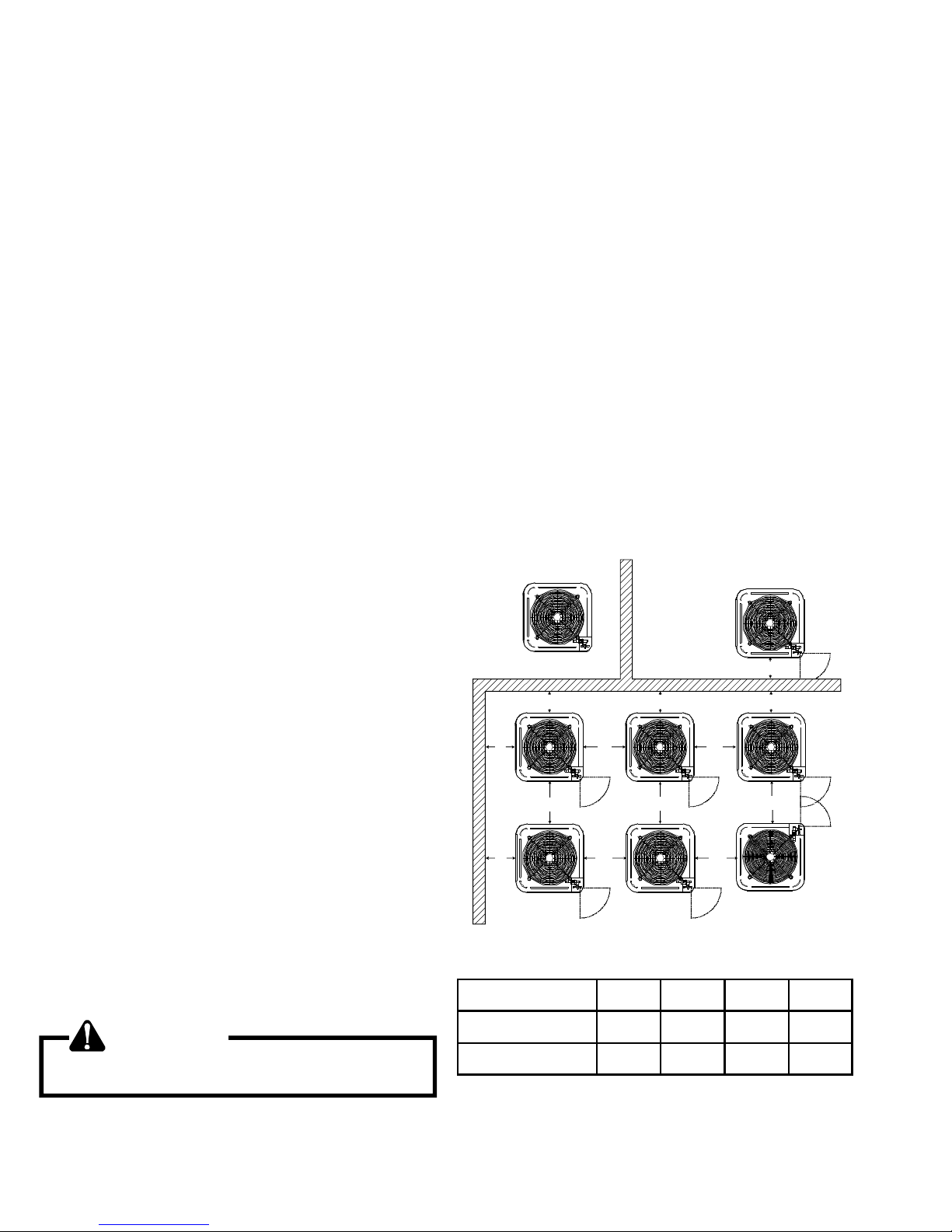
This unit is for outdoor installation only. Refer to figure for
minimum clearances from the sides of the unit to full walls
and other objects.
NOTE: This unit cannot be completely enclosed. At least
one side must be unrestricted.
These clearances will help avoid air recirculation. If installing
two or more units at the same location, allow at least 24
inches between units. If only one side is restricted (for example, against the outside wall of a house), the unit may be
placed as close as 8" to that one wall.
DO NOT locate the unit:
* Directly under a vent termination for a gas appliance.
* Within 3 feet of a clothes drier vent
* Where the refreezing of defrost water would create
a hazard
* Where water may rise into the unit.
NOT
RECOMMENDED
B B B
®
AA AAA
C
AA
A
Model Type A B C AA
AA
AA
C
AA
CC
B
AA
OK!
OK!
OK!
OK!
OK!
OK!
WARNING
To avoid possible injury, explosion or death, practice
safe handling of refrigerants.
4
Residential 10" 10" 18" 20"
Light Commercial 12' 12" 18" 24"
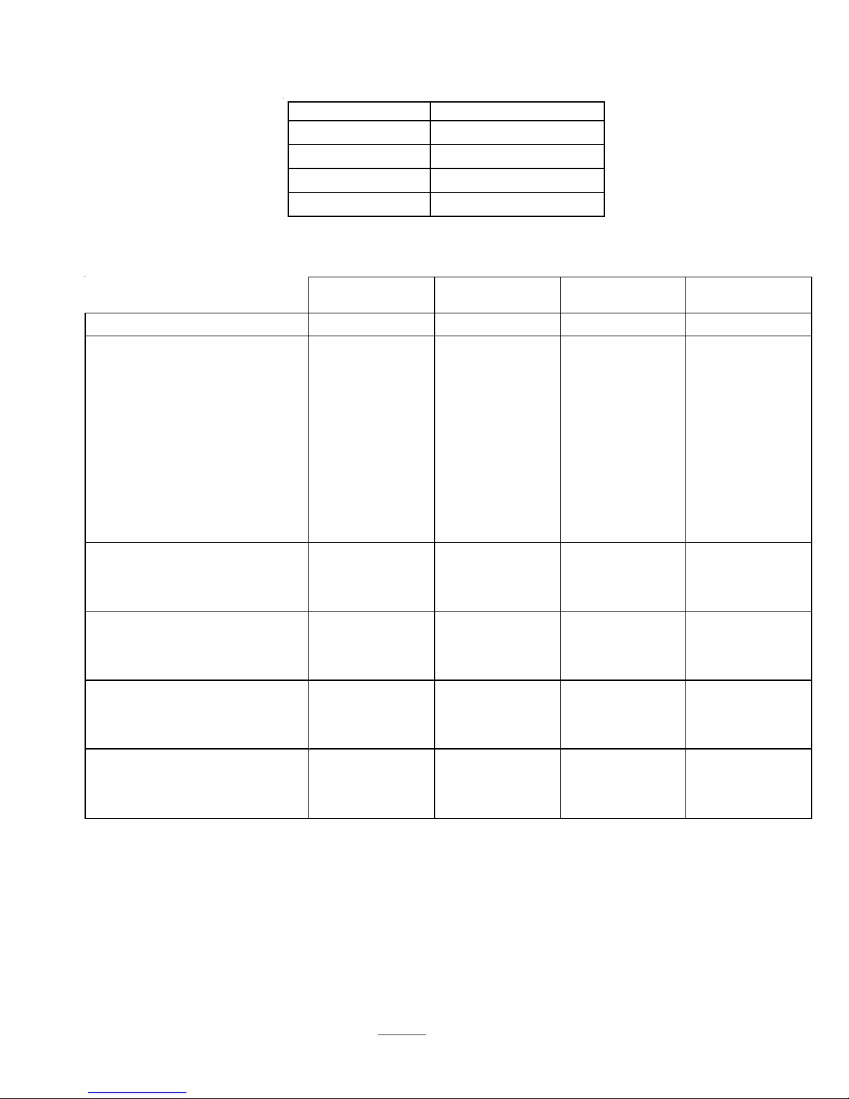
CONDENSING UNIT SPECIFICATIONS
A/DSXC160[24-60]1A*
Dimensions
Model Dimensions - W x D x H
*SXC160241A* 29 x 29 x 32¼
*SXC160361A* 29 x 29 x 38¼
*SXC160481A* 35½ x 35½ x 38¼
*SXC160601A* 35½ x 35½ x 38¼
A/DSXC160241A* - A/DSXC160601A*
*S XC160241A* *SXC16036A* *SXC160481A* *SXC160601A*
Cooling Capac it y, B TUH 24,000 36,000 48,00 0 60,000
Com pressor
R.L. Am ps 10.3 16.7 21.2 25.6
L.R. Am ps 52.0 82.0 96.0 118.0
Low Pressure Switch
Open 22 PS IG 22 PS IG 22 PS IG 22 PS IG
Close 50 PS IG 50 PS IG 50 PS IG 50 PS IG
High Pressure Switch
Open 610 P S IG 610 P S IG 610 P SIG 610 P S IG
Close 420 P S IG 420 P S IG 420 P SIG 420 P S IG
Condens er Fan M otor
Horsepower 1/12 1/6 1/6 1/6
F.L. A mps 0.6 1.0 1.0 1.0
Liquid Line, Inc he s O . D. * 3/8" 3/8" 3/8" 3/ 8"
Suc t ion Line, Inc hes O.D. * 3/4" 7/8" 1-1/8" 1-1/8"
Refrigerant Charge 137.0 157.0 202.0 197.0
Powe r Supply 208/230-60-1 208/ 230-60-1 208/2 30-60-1 208/230 -60-1
Minim um Circ uit A m pac it y
Maxim um O vercurrent Device
Elec t rical Conduit S iz e
Power S upply (Inches ) 1/2 or 3/4 1/2 or 3/ 4 1/ 2 or 3/4 1/2 or 3/4
(1)
(2)
13.5 21.9 27.5 33.0
20 35 45 50
App rox im at e Shipp ing Weight 282 282 296 296
*
Up to 24' in equivalent line length
(1)
Wire size should be determined in accordance with National Electrical Codes; extensive wire runs will require larger wire sizes.
(2)
Maximum Overcurrent Protection Device: MUST use Time Delay Fuse or HACR type Circuit Breaker of the same size as noted.
NOTES:
• Always check the S & R plate for electrical data on the unit being installed.
• Installer will need to supply 7/8" to 1-1/8" adapters for suction line connections (4 & 5 ton units).
• Installer will need to supply 3/4" to 7/8" adapters for suction line connections (3 ton unit).
• Unit is charged with refrigerant for 15' of 3/8" liquid line. System charge must be adjusted per Installation Instructions Final Charge
Procedure.
• Installation of these units requires the specified TXV Kit to be installed on the indoor coil. THE SPECIFIED TXV IS DETERMINED BY THE
OUTDOOR UNIT, NOT THE INDOOR COIL.
NOTE: This data is provided as a guide, it is important to electrically connect the unit and properly size fuses/circuit breakers and
wires in accordance with all national and/or local electrical codes. Use copper wire only.
Unit specifications are subject to change without notice. ALWAYS refer to the unit's serial plate for the most up-to-date general
and electrical information.
5
CONDENSING UNIT SPECIFICATIONS
ASXC160[24-36]1B*
Dimensions
Model Dim ensions - W x D x H
ASX C160241B* 29 x 29 x 30¼
ASX C160361B* 29 x 29 x 30¼
ASXC160241BB A SXC160241BC ASXC160361BB ASXC 16 0361 B C
Cooling Capa c ity , BTUH 24,000 24,000 36,0 00 36,000
Com pressor
R.L. Am ps 10.3 11.7 16. 7 15 .3
L.R. Am ps 52.0 58.3 82. 0 83 .0
Low Pres s ure S wit c h
Open 22 P S IG 22 P S IG 22 PS IG 22 P S IG
Clos e 50 P S IG 50 P S IG 50 PS IG 50 P S IG
High P ress ure S wit c h
Open 610 P S IG 610 P S IG 610 P SIG 610 P S IG
Clos e 420 PS IG 420 PS IG 420 P S IG 420 P S IG
Condenser F an Mot or
Horsepo we r 1/ 6 1/6 1/6 1/6
F.L. A m ps 1.1 1.1 0. 9 0.9
Liquid Line, Inches O .D. * 3/8" 3/8" 3/8" 3/8"
S uct ion Line , Inch es O . D.* 3/4 " 3/ 4" 7/ 8" 7 /8"
Refrigerant Charge 100.0 88.0 110.0 96.0
P ower Su pply 208/23 0-60-1 208/230 -60-1 208/230-60 -1 208/230-60-1
Min im um C irc uit Ampac it y
(1)
Maximum Overcurrent Device
(2)
14.0 15.7 21. 8 20.0
20 20 35 35
E lec tric al Conduit S iz e
Power Supply (Inches) 1/2 or 3/4 1/2 or 3/4 1/2 or 3/4 1/2 or 3/4
Approximate Shipping Weight 198 198 202 202
*
Up to 24' in equivalent line length
(1)
Wire size should be determined in accordance with National Electrical Codes; extensive wire runs will require larger wire sizes.
(2)
Maximum Overcurrent Protection Device: MUST use Time Delay Fuse or HACR type Circuit Breaker of the same size as noted.
NOTES:
• Always check the S & R plate for electrical data on the unit being installed.
• Installer will need to supply 7/8" to 1-1/8" adapters for suction line connections (4 & 5 ton units).
• Installer will need to supply 3/4" to 7/8" adapters for suction line connections (3 ton unit).
• Unit is charged with refrigerant for 15' of 3/8" liquid line. System charge must be adjusted per Installation Instructions Final Charge
Procedure.
• Installation of these units requires the specified TXV Kit to be installed on the indoor coil. THE SPECIFIED TXV IS DETERMINED BY THE
OUTDOOR UNIT, NOT THE INDOOR COIL.
NOTE: This data is provided as a guide, it is important to electrically connect the unit and properly size fuses/circuit
breakers and wires in accordance with all national and/or local electrical codes. Use copper wire only.
6
CONDENSING UNIT SPECIFICATIONS
ASXC160[48-60]1B*
Dimensions
Model Dim ensions - W x D x H
ASX C160481B* 35½ x 35½ x 36¼
ASX C160601B* 35½ x 35½ x 38¼
AS XC160481B* AS XC160481BC ASXC 160601B * A SXC 160601BC
Cooling Capacity, BTUH 48,000 48,000 60,000 60,000
Com pressor
R.L. A mps 21.2 21.2 25.6 28.8
L.R. A mps 96.0 104.0 118. 0 152.9
Low Pressure Switch
Open 55 PSIG 55 PS IG 22 PS IG 22 PS IG
Close 95 PS IG 95 PS IG 50 PSIG 50 PS IG
High Pressure Switch
Open 610 PS IG 610 PS IG 610 PS IG 610 PS IG
Close 420 PS IG 420 P S IG 420 P S IG 420 P S IG
Condenser Fan M otor
Horsepower 1/6 1/6 1/6 1/6
F.L. Am ps 1. 0 1.2 1.0 1.2
Liquid Line, Inc hes O. D.* 3/8" 3/ 8" 3/8" 3/8"
Suc t ion Line, Inches O . D.* 1 1/8" 1 1/8" 1 1/ 8" 1 1/8"
Refrigerant Charge 135.0 135.0 200.0 200.0
Power S upply 208/230-60-1 208/230-60-1 208/230-60-1 208/ 230-60-1
M inimum Circ uit A m pac ity
Maximum Overcurrent Device
Elec tric al Conduit S ize
Power Supply (Inc hes) 1/2 or 3/4 1/2 or 3/4 1/2 or 3/4 1/2 or 3/4
Approxim ate S hipping W eight 241 241 301 301
*
Up to 24' in equivalent line length
(1)
Wire size should be determined in accordance with National Electrical Codes; extensive wire runs will require larger wire sizes.
(2)
Maximum Overcurrent Protection Device: MUST use Time Delay Fuse or HACR type Circuit Breaker of the same size as noted.
NOTES:
• Always check the S & R plate for electrical data on the unit being installed.
• Installer will need to supply 7/8" to 1-1/8" adapters for suction line connections (4 & 5 ton units).
• Installer will need to supply 3/4" to 7/8" adapters for suction line connections (3 ton unit).
• Unit is charged with refrigerant for 15' of 3/8" liquid line. System charge must be adjusted per Installation Instructions Final Charge
Procedure.
• Installation of these units requires the specified TXV Kit to be installed on the indoor coil. THE SPECIFIED TXV IS DETERMINED BY THE
OUTDOOR UNIT, NOT THE INDOOR COIL.
(1)
(2)
27.5 27.7 33.0 37.2
45 45 50 60
NOTE: This data is provided as a guide, it is important to electrically connect the unit and properly size fuses/circuit breakers and
wires in accordance with all national and/or local electrical codes. Use copper wire only.
Unit specifications are subject to change without notice. ALWAYS refer to the unit's serial plate for the most up-to-date general
and electrical information.
7
CONDENSING UNIT SPECIFICATIONS
DSXC160[24-36]1A*
Dimensions
Model Dimensions - W x D x H
DSXC160241A * 29 x 29 x 30¼
DSXC160361A * 29 x 29 x 30¼
DSX C160241AB DSX C160241AC DSXC160361AB DSXC160 361AC
Cooling Capaci ty, BTUH 24,000 24,000 36,000 36, 000
Compressor
R.L. Amps 10.3 11.7 16.7 15.3
L.R. Amps 52.0 58.3 82.0 83.0
Low Pressure Switch
Open 22 P S IG 22 PSIG 22 PSIG 22 PSIG
Close 50 PS IG 50 PSIG 50 PSIG 50 PSIG
High Pressure Switch
Open 610 PSIG 610 PS IG 610 PS IG 610 P S IG
Close 420 PS IG 420 PS IG 420 P S IG 420 PSIG
Condenser Fan Motor
Horsepower 1/6 1/6 1/6 1/6
F.L. Am ps 1.1 1.1 0.9 0.9
Liquid Line, Inches O. D. * 3/8" 3/ 8" 3/ 8" 3/8"
Suc tion Line, Inches O .D.* 3/ 4" 3/4" 7/ 8" 7/8"
Refrigerant Charge 100.0 88.0 110.0 96.0
Power Supply 208/230-60-1 208/230-60-1 208/230-60-1 208/230-60-1
Minim um Circ ui t Am pac it y
Maximum Overcurrent Device
Electri cal Conduit Size
Power Supply (Inches) 1/2 or 3/ 4 1/2 or 3/ 4 1/2 or 3/4 1/2 or 3/4
Approximate Shipping Weight 198 198 202 202
*
Up to 24' in equivalent line length
(1)
Wire size should be determined in accordance with National Electrical Codes; extensive wire runs will require larger wire sizes.
(2)
Maximum Overcurrent Protection Device: MUST use Time Delay Fuse or HACR type Circuit Breaker of the same size as noted.
NOTES:
• Always check the S & R plate for electrical data on the unit being installed.
• Installer will need to supply 7/8" to 1-1/8" adapters for suction line connections (4 & 5 ton units).
• Installer will need to supply 3/4" to 7/8" adapters for suction line connections (3 ton unit).
• Unit is charged with refrigerant for 15' of 3/8" liquid line. System charge must be adjusted per Installation Instructions Final Charge
Procedure.
• Installation of these units requires the specified TXV Kit to be installed on the indoor coil. THE SPECIFIED TXV IS DETERMINED BY THE
OUTDOOR UNIT, NOT THE INDOOR COIL.
(1)
(2)
14.0 15.7 21.8 20.0
20 20 35 35
NOTE: This data is provided as a guide, it is important to electrically connect the unit and properly size fuses/circuit
breakers and wires in accordance with all national and/or local electrical codes. Use copper wire only.
8
CONDENSING UNIT SPECIFICATIONS
DSXC160[48-60]1B*
Dimensions
Model Dimensions - W x D x H
DSXC160481B* 35½ x 35½ x 36¼
DSXC160601B* 35½ x 35½ x 38¼
DSXC160481B* D SXC16048 1BC DSXC160601B* DSXC160601BC
Cooling Capacity , BTUH 48,000 48,000 60,000 60,000
Compressor
R.L . A m ps 21. 2 21. 2 25. 6 2 8. 8
L. R. A m ps 96. 0 104. 0 118.0 1 52.9
Low Pressure Switch
Open 55 PSIG 55 PSIG 22 PSIG 22 PSIG
Close 95 PSIG 95 PSIG 50 PSIG 50 PSIG
High Press u re Sw i tch
Open 610 PSIG 610 PSIG 610 PSIG 610 P SIG
Close 420 PSIG 420 PSIG 420 PSIG 420 PSIG
Conden ser F a n Mot o r
Horsepower 1/6 1/6 1/6 1/6
F.L. Amps 1.0 1.2 1.0 1. 2
Liquid Line, Inches O.D.* 3/8" 3/8" 3/8" 3/8"
Suct i on Line, Inc hes O. D. * 1 1/8" 1 1/8" 1 1/8" 1 1/8"
Refrigerant Charge 135.0 135.0 200.0 200.0
Power Supply 208/230-60-1 208/230-60-1 208/230-60-1 208/230-60-1
Minimum Circuit Ampac ity
Maximum Overcurrent Device
Elec t ric al Conduit S i z e
Power Supply (Inches) 1/ 2 or 3/4 1/ 2 or 3/4 1/2 or 3/4 1/2 or 3/4
Approximat e Shipping Weight 241 241 301 301
*
Up to 24' in equivalent line length
(1)
Wire size should be determined in accordance with National Electrical Codes; extensive wire runs will require larger wire sizes.
(2)
Maximum Overcurrent Protection Device: MUST use Time Delay Fuse or HACR type Circuit Breaker of the same size as noted.
NOTES:
• Always check the S & R plate for electrical data on the unit being installed.
• Installer will need to supply 7/8" to 1-1/8" adapters for suction line connections (4 & 5 ton units).
• Installer will need to supply 3/4" to 7/8" adapters for suction line connections (3 ton unit).
• Unit is charged with refrigerant for 15' of 3/8" liquid line. System charge must be adjusted per Installation Instructions Final Charge
Procedure.
• Installation of these units requires the specified TXV Kit to be installed on the indoor coil. THE SPECIFIED TXV IS DETERMINED BY THE
OUTDOOR UNIT, NOT THE INDOOR COIL.
(1)
(2)
27.5 27.7 33.0 37.7
45 45 50 60
NOTE: This data is provided as a guide, it is important to electrically connect the unit and properly size fuses/circuit breakers and
wires in accordance with all national and/or local electrical codes. Use copper wire only.
Unit specifications are subject to change without notice. ALWAYS refer to the unit's serial plate for the most up-to-date general
and electrical information.
9
PERFORMANCE DA T A
5
5
5
IDB*
fl
w
9
63
1
9
6
1
9
63
6
1
9
6
1
9
63
6
1
9
1
-
-
-
-
-
-
A
-
-
-
-
R
-
-
-
-
-
-
-
-
A
-
-
-
-
R
-
-
-
-
-
-
-
-
A
-
-
-
-
R
-
-
A
6
R
A
7
R
0
A
7
R
g
p
q
p
(
p
)
ASXC160241A*-LOW STAGE
.+fan
77
115
5
18 16 12
6.2 6.3 6.5
0.79 0.66 0.46
41 2 443 449
1.42 1.45 1.50
18 16 12
13 6 140 153
6.2 6.4 6.6
41 6 447 454
0.82 0.68 0.47
13 7 142 155
1.43 1.47 1.52
17 15 11
6.3 6.4 6.6
42 0 452 458
0.86 0.72 0.50
13 9 143 156
1.44 1.48 1.53
C O OLING OP ERAT ION
77
5
77
5
20 17 13
5.8 6.0 6.2
0.78 0.65 0.45
368 396 401
1.37 1.40 1.45
19 17 13
133 137 150
5.9 6.0 6.2
372 400 405
0.81 0.68 0.47
134 138 151
1.38 1.41 1.46
18 16 12
5.9 6.1 6.3
375 404 409
0.85 0.71 0.49
135 140 153
1.39 1.43 1.48
17 12 23 21 17 12 21 19 16 11
17.0 18.2 14.5 14.9 16.2 17.3 13.4 13.8 15.0 16.1
15.7
5.8 6.0 5.8 6.0 6.2 6.4 6.2 6.3 6. 5 6.8
21
5.
5.8 6.1 5.9 6.0 6.2 6.4 6.2 6.4 6. 6 6.8
16 11 21 20 16 11 20 18 15 10
5.9 6.1 5.9 6.1 6.3 6.5 6.3 6.4 6. 6 6.9
0.63 0.41 0.97 0.87 0.66 0.42 0.98 0.87 0.66 0.43
0.84
364 372 375 404 409 418 420 452 458 468
1.41 1.46 1.39 1.43 1.48 1.53 1.44 1.48 1.53 1.58
35 9
1.37
com
s
MPS =o ut d oo r un it am
77
Outdoor Ambient Temperature
85 95 10
Entering Indoor W et Bu lb Tem perature
5
77
7
EXPANDED PERFORMANCE DA TA
5
77
6
5
S/T 0.69 0.58 0.40 - 0.71 0.60 0.41 - 0.73 0.61 0.42 - 0. 76 0.63 0.44
MBh 16.1 16. 7 18.3 - 15.8 16.3 17.9 - 15.4 15.9 17.5 - 15.0 15.6 17.0 - 14.3 14.8 16.2 - 13.2 13.7 15.0 -
Delta T 19 17 13 - 20 17 13 - 20 17 13 - 20 17 13
o
r
119 123 134 - 123 127 138 - 127 131 143 - 130 134 147
MPS 4.4 4.5 4.6 - 4.7 4.8 5.0 - 5.1 5.3 5.4 - 5.5 5.6 5.8
HI PR 223 240 244 - 252 271 275 - 287 309 313 - 327 352 357
525 KW 1.08 1.10 1.14 - 1.17 1.19 1.23 - 1.24 1.27 1.31 - 1.31 1.34 1.39
S/T 0.71 0.60 0.41 - 0.74 0.62 0.43 - 0.76 0.63 0.44 - 0. 78 0.65 0.45
MBh 17.5 18. 1 19.8 - 17.1 17.7 19.4 - 16.7 17.3 18.9 - 16.3 16.8 18.5 - 15.4 16.0 17.5 - 14.3 14.8 16.2 -
LO P
Delta T 19 17 13 - 19 17 13 - 19 17 13 - 20 17 13
120 124 136 - 124 128 140 - 128 132 144 - 132 136 148
MPS 4.4 4.5 4.7 - 4.8 4.9 5.0 - 5.2 5.3 5.5 - 5.5 5.7 5.8
HI PR 226 243 246 - 255 274 278 - 290 312 316 - 330 355 360
S/T 0.75 0.63 0.43 - 0.78 0.65 0.45 - 0.80 0.66 0.46 - 0. 82 0.69 0.48
MBh 18.0 18. 7 20.4 - 17.6 18.2 20.0 - 17.2 17.8 19.5 - 16.7 17.4 19.0 - 15.9 16.5 18.1 - 14.7 15.3 16.7 -
LO P
Delta T 18 16 12 - 19 16 12 - 19 16 12 - 19 16 12
122 125 137 - 125 129 141 - 129 133 146 - 133 137 150
MPS 4.5 4.6 4.7 - 4.8 4.9 5.1 - 5.2 5.3 5.5 - 5.6 5.7 5.9
HI PR 228 245 248 - 258 277 281 - 293 315 319 - 334 359 364
LO P
675 KW 1.10 1.12 1.16 - 1.19 1.21 1.25 - 1.26 1.29 1.34 - 1.33 1.37 1.41
MBh 16.416.918.319.616.016.517.919.215.616.117.418.715.3
S/T 0.78 0.70 0 .53 0.34 0.81 0.73 0.55 0.35 0.83 0.74 0.56 0.36 0.86 0.77 0.58 0.37 0.89 0.80 0.60 0.39 0.90 0.80 0.61 0.39
Delta T222117122321171223211712 23
119 123 134 143 123 127 138 147 127 131 143 152 130 134 147 156 133 137 150 159 136 140 153 163
MPS 4.4 4.5 4.6 4.8 4.7 4.8 5.0 5.2 5.1 5.3 5.4 5.6 5.5
HI PR 223 240 244 249 252 271 275 281 287 309 313 320 327 352 357 364 368 396 401 410 412 443 449 459
525 KW 1.08 1.10 1 .14 1.18 1.17 1.19 1.23 1 .27 1.24 1.27 1.31 1.36 1 .31 1.34 1.39 1.44 1.37 1.40 1.45 1.50 1.42 1.45 1.50 1.56
S/T 0.81 0.73 0 .55 0.35 0.84 0.75 0.57 0.37 0.86 0.77 0.58 0.38 0.89 0.80 0.60 0.39 0.92 0.83 0.63 0.40 0.93 0.83 0.63 0.41
MBh 17.818.319.821.317.417.919.320.816.917.418.920.316.5 17.0 18.4 19.8 15.7 16.2 17.5 18.8 14.5 15.0 16.2 17.4
LO P
Delta T222017122221171222211712 23 21 17 12 22 20 17 12 21 19 16 11
120 124 136 144 124 128 140 149 128 132 144 154 132 136 148 158 134 138 151 161 137 142 155 165
MPS 4.4 4.5 4.7 4.8 4.8 4.9 5.0 5.2 5.2 5.3 5.5 5.7 5.5 5.
S/T 0.85 0.76 0 .58 0.37 0.88 0.79 0.60 0.38 0.90 0.81 0.61 0.39 0.93
MBh 18.318.820.421.917.918.419.921.417.518.019.420.917.0 17.5 19.0 20.4 16.2 16.7 18.0 19.3 15.0 15.4 16.7 17.9
HI PR 226 243 246 251 255 274 278 284 290 312 316 323 330 355 360 368 372 400 405 414 416 447 454 464
LO P
MPS 4.5 4.6 4.7 4.9 4.8 4.9 5.1 5.3 5.2 5.3 5.5 5.7 5.6 5.
HI PR 228 245 248 254 258 277 281 287 293 315 319 326 334
Delta T212016112120161122201611 22 2
675 KW 1.10 1.12 1 .16 1.20 1.19 1.21 1.25 1 .30 1.26 1.29 1.34 1.38 1 .33
uid and suction service valves.
122 125 137 146 125 129 141 150 129 133 146 155 133 137 150 159 135 140 153 162 139 143 156 166
LO P
res s ures are m easu red at the li
10
M O DE L : *SXC 16 0241A * / CA*F 363 6C6 ** + TXV / MBV C 1200**-1 **, Des ign Su bc oo ling @ AHR I 95°F Co n ditions, 5°F @ Ser v. Vlv .
70 600 KW 1.09 1.11 1.15 - 1.18 1.20 1.24 - 1.25 1.28 1.33 - 1. 32 1.35 1.40
75 600 KW 1.09 1.11 1.15 1.19 1.18 1.20 1.24 1.29 1.25 1.28 1.33 1.37 1.32 1.35 1.40 1.45 1.38 1.41 1.46 1.51 1.43 1.47 1.52 1.57
h and low
* Entering Indoo r Dry Bulb Tempe rature NO TE: Shad ed area is ACCA (TVA) cond itions KW=To tal system pow er
Hi
PERFORMANCE DA T A AS XC1 6 0241 A *- LOW S TAG E
A
g
e
IDB*
fl
w
63
59
67
71
63
67
59
67
71
63
675963
71
6
6
9
9
3
8
5
7
5
8
8
7
9
3
7
R
5
7
9
3
7
R
8
7
7
3
7
A
S
7
8
8
9
3
5
7
5
7
R
8
6
3
R
9
8
3
3
6
A
S
5
7
9
8
9
3
3
5
7
6
7
R
7
3
5
9
6
R
9
3
6
5
3
7
8
3
6
9
5
8
8
7
9
3
7
A
S
6
8
7
8
3
6
5
6
R
5
7
9
3
7
R
8
7
7
3
3
6
7
3
8
6
5
5
A
S
7
8
8
9
3
5
7
5
7
R
8
6
3
R
9
8
8
5
9
8
8
3
A
S
5
7
9
8
9
3
3
5
7
6
7
R
9
3
6
5
3
24 23 20 16
C OOLI NG OPER AT ION
21 17 25 24 21 1
352 357 364 368 396 401 410 412 443 449 459
320 32
152 130 134 147 156 133 137 150 159 136 140 153 163
Indoor W et Bulb Temperatur
Outdoor Am bien t Temperature
Enterin
31
30
131 14
23 22 19 15
5.8 6.15.96.06.26.46.26.46.66.8
5.
5.
330 355 360 368 372 400 405 414 416 447 454 464
5.
32
5.
132 144 154 132 136 148 158 134 138 151 161 137 142 155 165
21 21 19 15
21 23 24 23 20
20 1
2 0 16 22 2
5.9 6.1 5.9 6.1 6.3 6.5 6.3 6 .4 6.6 6.9
5.
137 150 159 135 140 153 162 139 143 156 166
5.
334 359 364 372 375 404 409 418 420 452 458 468
13
5.
32
15
5.
31
14
31
13
5.8 6.0 5.8 6.0 6.2 6.4 6.2 6 .3 6.5 6.8
5.
0.95 0.86 0.70 1.00 0. 99 0.89 0.72 1.00 1.00 0.90 0.73
352 357 364 368 396 401 410 412 443 449 459
5.
320 32
5.4 5.
31
30
2
2 5 22 25 2
5.8 6.1 5.9 6.0 6.2 6.4 6.2 6 .4 6.6 6.8
5.
5.
330 355 360 368 372 400 405 414 416 447 454 464
152 130 134 147 156 133 137 150 159 136 140 153 163
131 14
5.
32
5.
24 20 21 22 22 19
5.9 6.1 5.9 6.1 6.3 6.5 6.3 6 .4 6.6 6.9
5.
137 150 159 135 140 153 162 139 143 156 166
5.
13
5.
15
5.
14
132 144 154 132 136 148 158 134 138 151 161 137 142 155 165
13
1.24 1.27 1.31 1.36 1.31 1.34 1.39 1.44 1.37 1.40 1.45 1.50 1.42 1.45 1.50 1.56
1.2
1.2
1.1
1.1
1.10 1.14 1.1
KW 1.0
Delta T25242117252421172524211726 2
52
281 28
223 240 244 249 252 271 27
HI P
AMPS4.44.54.64.84.74.85.05.25.15.35.45.65.5 5.6 5.86.05.86.06.26.46.26.36.56.8
0 . 51 0 . 91 0 . 86 0 . 70 0.52 0.9 4 0.88 0.72 0.54 0.98 0.92 0.75 0.56 0.99 0.92 0.75 0.56
0.6
EXPANDED PERFORMANCE DA T
65 75 8 5 95 105 115
0.8
0.8
0.4
0.81 0.6
S/T 0.8
MBh 16.7 17.1 18.2 19.5 16.3 16.7 17.8 19.0 15.9 16.3 17.4 18.6 15.5 15.9 17.0 18.1 14.8 15.1 16.1 17.2 13.7 14.0 14.9 15.9
o
r
M O DE L : *SX C16 0241A * / C A *F3 63 6C6** + TX V / MBV C 1200**-1 **, Des ign Su bc oo ling @ A H R I 95°F Co n diti ons, 5°F @ Serv. Vlv .
S/ T 0. 93 0.88 0 . 71 0.53 0.97 0.91 0.74 0.55 1.00 0.93 0 .76 0.57 1.00 0.9 6 0.78 0.5 8 1.0 0 1.0 0 0.81 0.61 1.00 1.00 0.8 2 0.61
Delta T24232016242320162423201624 2
675 KW 1.10 1.12 1. 16 1.20 1 .19 1.21 1.25 1.30 1.26 1.29 1.34 1.3 8 1.33 1.37 1.41 1.46 1.39 1.43 1.4 8 1.5 3 1.4 4 1.48 1.5 3 1.58
5.2 5.
5.1 5.
4.
4.
4.
4.6 4.
4.
MP
29
228 245 248 254 258 277 281 28
HI P
0.96 0.92 0.83 0.68 0. 9
0.90 0.81 0.6
0.64 0.9
0.7
122 125 137 146 125 129 141 150 12
S/T 0.90 0 .8
MBh 17.0 17.3 18.1 19.3 16.6 16.9 17.7 18.9 16.2 16.5 17.3 18.4 15.8 16.1 16.9 18.0 15.0 15.3 16.0 17.1 13.9 14.2 14.8 15.8
LO P
Delta T27262522272725222727252227 27 25222626252224252320
12
1.24 1.27 1.31 1.36 1.31 1.34 1.39 1.44 1.37 1.40 1.45 1.50 1.42 1.45 1.50 1.56
281 28
1.2
5.0 5.2 5. 1 5.
1.2
4.
1.1
4.
1.1
4.
1.10 1.14 1.1
4.4 4.5 4.
223 240 244 249 252 271 27
MP
KW 1.0
HI P
52
0.99 0.96 0.86 0.70 1.00 0.99 0.89 0.72 1.00 1.00 0.93 0.75 1.00 1.00 0.93 0.76
14
0.84 0.6
0.9
0.9
0.90 0.81 0.6
119 123 134 143 123 127 13
S/T 0.9
MBh 18.4 18.8 19.6 21.0 18.0 18.3 19.2 20.5 17.5 17.9 18.7 20.0 17.1 17.4 18.3 19.5 16.3 16.6 17.4 18.5 15.1 15.4 16.1 17.2
LO P
Delta T26262421272625212726252126 2
12
284 290 312 31
5.0 5.2 5. 2 5.
4.
4.
4.
4.4 4.5 4.
226 243 246 251 255 274 27
120 124 136 144 124 128 140 14
MP
MBh 19.0 19.3 20.2 21.6 18.5 18.9 19.8 21.1 18.1 18.4 19.3 20.6 17.6 18.0 18.8 20.1 16.8 17.1 17.9 19.1 15.5 15.8 16.6 17.7
HI P
LO P
8 5 600 KW 1.09 1.11 1. 15 1.19 1 .18 1.20 1.24 1.29 1.25 1.28 1.33 1.3 7 1.32 1.3 5 1.40 1.4 5 1.3 8 1.4 1 1.46 1.51 1.43 1.47 1.5 2 1.57
12
14
119 123 134 143 123 127 13
S/ T 0. 89 0.84 0 . 68 0.51 0.92 0.87 0.70 0.53 0.95 0.89 0 .72 0.54 0.98 0.9 2 0.75 0.56 1.00 0. 95 0.77 0.58 1.00 0.96 0. 78 0. 58
MBh 18. 1 18.5 19.7 21.1 17.7 18.1 19.3 20.6 17.2 17.6 18.8 20.1 16.8 17.2 18. 4 19.6 16.0 16.3 17.4 18.7 14.8 15.1 16.2 17.3
LO P
Delta T25242116252421172524211725 24 21 17 24 24 2 1 1
12
284 290 312 31
5.0 5.2 5. 2 5.
4.
4.
4.
4.4 4.5 4.
226 243 246 251 255 274 27
120 124 136 144 124 128 140 14
MP
MBh 18.6 19.0 20.3 21.7 18.2 18.6 19.9 21.2 17.8 18.1 19.4 20.7 17.3 17.7 18.9 20.2 16.5 16.8 18.0 19.2 15.2 15.6 16.6 17.8
HI P
LO P
8 0 600 KW 1.09 1.11 1. 15 1.19 1 .18 1.20 1.24 1.29 1.25 1.28 1.33 1.3 7 1.32 1.3 5 1.40 1.45 1.38 1. 41 1.46 1.51 1.43 1.47 1. 52 1. 57
5.2 5.
0 . 72 1 . 00 1 . 00 0 . 91 0.73 1.0 0 1.00 0.93 0.76 1.00 1.00 0.97 0.79 1.00 1.00 0.98 0.79
5.1 5.
0.8
4.
4.
1.00 0.9
4.
0.6
4.6 4.
0.94 0.8
4.
122 125 137 146 125 129 141 150 12
MP
S/T 0.9
HI PR 228 245 248 254 258 277 281 287 293 315 319 326 334 359 364 372 375 404 409 418 420 452 458 468
Delta T 25.27 25 23 20 25 25 24 21 25 25 24 21 24 24 24 21 23 2
LO P
675 KW 1.10 1.12 1. 16 1.20 1 .19 1.21 1.25 1.30 1.26 1.29 1.34 1.3 8 1.33 1.37 1.41 1.46 1.39 1.43 1.4 8 1.5 3 1.4 4 1.48 1.5 3 1.58
* Entering I ndoor Dry Bulb Temperature NOTE: Shaded area is AHRI Rat ing Conditions KW=Total system power
High and low pressures are measured at the liquid and suction service valves. AMPS=o ut doo r un it amps (com p. +f an)
11
PERFORMANCE DA T A AS XC1 6 0241 B* -LOW S TA GE
p
5
5
g
p
w
3
7
9
3
7
9
3
-
-
-
-
-
-
A
-
-
-
-
R
-
-
-
-
-
-
-
-
A
-
-
-
-
R
-
-
-
-
-
-
-
-
A
-
-
-
-
R
-
-
A
R
A
R
0
A
R
g
(
)
67 71
115
6
19 16 12
5.7 5.8 6 .0
0.75 0.63 0.44
C OOLING OP ER ATION
71 5
0.75 0.62 0.43
67 7 1 59 63 6
erature
6
erature
71 5
350 377 398
1.34 1.37 1.42
20 17 13
5.4 5.5 5.7
31 7 341 360
1.30 1.32 1.37
18 16 12
123 131 143
11 9 126 138
5.8 6.0 6 .2
361 389 411
0.78 0.65 0.45
20 17 13
0.77 0.65 0.45
127 135 147
1.38 1.41 1.46
5.5 5.7 5.8
32 7 352 372
12 3 130 142
1.33 1.36 1.41
17 15 11
5.9 6.0 6 .2
365 393 415
0.82 0.68 0.47
19 16 12
0.81 0.68 0.47
128 136 149
1.39 1.42 1.47
5.6 5.7 5.9
33 0 355 375
12 4 132 144
1.34 1.37 1.42
17 11 22 20 16 11 20 19 15 11
133 142 120 128 139 149 124 132 144 154
324 338 320 345 364 380 354 381 402 420
17 .7 18 . 9 15. 0 15 .5 16 .8 18 .0 13 .9 14.4 15.5 16.7
306
16 .3
5.6 5.8 5.6 5.8 5.9 6.2 5.9 6 .1 6.3 6.5
2
5.4
comp.+fan
MPS =o ut d oo r un it amp s
6
Indoor Wet Bulb Te m
Ou tdoor Am bi en t Tem
Enterin
75 85 95 10
EXPA NDED PERFORMANCE DA TA
6
59 63 67 71 59 63 67 71 59 6
S/T 0.660.550.38 - 0.680.570.39 - 0.700.580.40 - 0.72 0.60 0.42
MBh 15.5 16.0 17.6 - 15.1 15.6 17.1 - 14.7 15.3 16.7 - 14.4 14.9 16.3 - 13.7 14.2 15.5 - 12.7 13.1 14.4 -
Delta T 20 17 13 - 20 17 13 - 20 17 13 - 20 17 13
98 105 114 - 104 111 121 - 108 115 125 - 113 121 132
MPS 4.1 4.2 4.3 - 4.4 4.5 4.6 - 4.8 4.9 5.0 - 5.1 5.2 5.4
S/T 0.680.570.39 - 0.700.590.41 - 0.720.600.42 - 0.75 0.62 0.43
MBh 16.7 17.4 19.0 - 16.4 17.0 18.6 - 16.0 16.5 18.1 - 15.6 16.1 17.7 - 14.8 15.3 16.8 - 13.7 14.2 15.6 -
HI PR 194 209 220 - 218 234 247 - 248 266 281 - 282 303 320
LO P
Delta T 19 17 13 - 20 17 13 - 20 17 13 - 20 17 13
101 108 118 - 107 114 124 - 111 118 129 - 117 124 136
MPS 4.2 4.3 4.4 - 4.5 4.6 4.8 - 4.9 5.0 5.2 - 5.2 5.3 5.5
HI PR 200 215 227 - 224 241 255 - 255 275 290 - 291 313 330
S/T 0.710.600.41 - 0.740.620.43 - 0.760.630.44 - 0.78 0.65 0.45
MBh 17.2 17.9 19.6 - 16.8 17.5 19.1 - 16.4 17.0 18.7 - 16.0 16.6 18.2 - 15.2 15.8 17.3 - 14.1 14.6 16.0 -
LO P
Delta T 19 16 12 - 19 16 12 - 19 16 12 - 19 16 12
102 109 119 - 108 115 126 - 112 120 131 - 118 126 137
MPS 4.2 4.3 4.5 - 4.6 4.7 4.8 - 4.9 5.0 5.2 - 5.3 5.4 5.5
HI PR 202 217 229 - 227 244 258 - 258 277 293 - 294 316 334
LO P
S/T 0.750.670.500.320.770.690.520.340.790.710.540.350.82 0.73 0.55 0.36 0.85 0.76 0.57 0.37 0.86 0.77 0.58 0.37
MBh 15.716.217.518.815.415.817.118.415.015.416.717.914.6 15.1 16.3 17 . 5 13. 9 14 .3 15 .5 16 .6 12 .9 13.2 14.3 15.4
Delta T23211712232117122321 1712 23 21 18 12 23 21 17 12 21 20 16 11
99 106 115 123 105 112 122 130 109 116 127 135 115
MPS 4.1 4.2 4.4 4.5 4.4 4.5 4.7 4.9 4.8 4.9 5.1 5.3 5.1 5.2 5.4 5.6 5.4 5.6 5.7 5.9 5.7 5 .9 6.1 6.3
S/T 0.770.690.520.340.800.720.540.350.820.730.560.360.85 0.76 0.57 0.37 0.88 0.79 0.60 0.38 0.89 0.79 0.60 0.39
MBh 17.017.519.020.416.617.118.519.916.216.718.119.415.8
HI PR 196 211 223 232 220 237 250 261 250 269 284 296 285
LO P
Delta T22211712232117122321 1712 23 21 17 12 23 21 17 12 21 19 16 11
102 109 119 127 108 115 126 134 112 120 131 139 118 126 137 146 124 132 144 153 128 136 149 158
MPS 4.2 4.3 4.5 4.6 4.6 4.7 4.8 5.0 4.9 5.0 5.2 5.4 5.3 5.4 5.6 5.8 5.6 5.7 5.9 6.1 5.9 6 .0 6.2 6.5
HI PR 202 217 230 239 227 244 258 269 258 277 293 306 294 316 334 348 330 355 375 391 365 393 415 433
S/T 0.810.730.550.350.840.750.570.370.860.770.580.380.89 0.80 0.60 0.39 0.92 0.83 0.62 0.40 0.93 0.83 0.63 0.41
MBh 17.518.119.521.017.117.619.120.516.717.218.620.016.3 16.8 18.2 19 . 5 15. 5 16 .0 17 .3 18 .5 14 .4 14.8 16.0 17.2
LO P
Delta T22201611222016112220 1611 22
103 110 120 128 109 116 127 135 114 121 132 141 119 127 139 148 125 133 145 155 129 138 150 160
MPS 4.3 4.4 4.5 4.7 4.6 4.7 4.9 5.0 5.0 5.1 5.3 5.4 5.3
HI PR 204 220 232 242 229 246 260 271 260 280 296 309 297 319 337 351 334 359 379 395 369 397 419 437
LO P
LOW STAGE
MO DEL: *SXC160241B* / CA *F3636*6**+TXV +MBVC1200**-1*
12
IDB* Airflo
473 KW 1.03 1.05 1.08 - 1.11 1.13 1.17 - 1.18 1.21 1.25 - 1.24 1.27 1.31
608 KW 1.06 1.09 1.12 - 1.15 1.17 1.21 - 1.22 1.25 1.29 - 1.29 1.31 1.36
70 540 KW 1.05 1.08 1.11 - 1.14 1.16 1.20 - 1.21 1.24 1.28 - 1. 27 1.30 1.35
473 KW 1.041.061.091.131.121.141.181.221.191.221.261.301.25 1.28 1.32 1.37 1.31 1.34 1.38 1.43 1.35 1.38 1.43 1.48
75 540 KW 1.061.091.121.161.151.171.211.251.221.251.291.331.29 1.31 1.36 1.40 1.34 1.37 1.42 1.47 1.39 1.42 1.47 1.52
608 KW 1.071.091.131.171.161.181.221.261.231.261.301.341.30 1.33 1.37 1.42 1.35 1.38 1.43 1.48 1.40 1.43 1.48 1.53
h and low pressures are measured at the liquid and suction service valves.
* Entering Indoo r Dry Bulb Temperature NOTE: Shaded area is ACCA (TVA) conditions KW=To tal system pow er
Hi
PERFORMANCE DA T A
A
5
5
5
w
9
9
3
9
3
9
3
A
R
A
R
A
R
A
R
A
R
A
R
67 71
115
6
Same as ASX160241C
C O OLING OPE RAT ION
67 71 5
6
17 25 24 21 17 24 23 20 16
18.8 15.3 15.6 16.7 17.9 14 .2 14.5 15.5 16.6
ASXC160241B*-LOW ST AGE
5.85.65.85.96.25.96.16.36.5
EXPANDED PERFORMANCE DA T
67 71 5
6
Outdoor Ambient Temperature
85 95 10
63 67 71 5
Entering I n door Wet Bulb Temperature
7
21
17 .6
5.6
6
59 63 67 71 59 63 67 71 5
S/T 0.82 0.77 0.62 0.47 0.85 0.79 0.65 0 .48 0.87 0.81 0.66 0.50 0 .90 0.84 0.68 0.51 0.93 0.8 7 0.71 0.53 0.94 0.88 0.72 0.54
Delta T252421172625211726252117 26 25 2217 2625211724232016
473 KW 1.05 1.07 1 .10 1.14 1.13 1.15 1.19 1.23 1.20 1.23 1.27 1.31 1 .26 1.29 1.33 1.38 1.32 1.35 1.39 1.44 1.36 1.40 1.44 1.49
MPS4.24.34.44.54.54.64.74.94.85.05.15.35.2 5.3 5.5 5.65.55.65.86.05.85.96.16.3
HI PR 198 213 225 235 222 239 252 263 253 272 287 299 288 310 327 341 324 348 368 384 358 385 406 424
MBh 16.0 16. 3 17.5 18.7 15.6 16.0 17.1 18.2 15.3 15.6 16.7 17.8 14.9 15.2 16.2 17.4 14.1 14.4 15.4 16.5 13.1 13.4 14.3 15.3
LOW STAGE
MO DEL: *SX C160241B* / CA *F3636*6**+TXV +MBVC1200**-1*
IDB* Airflo
100 107 117 124 106 113 123 131 110 117 128 136 116 123 134 143 121 129 141 150 125 133 146 155
S/T 0.85 0.80 0.65 0.48 0.88 0.82 0.67 0 .50 0.90 0.85 0.69 0.51 0 .93 0.87 0.71 0.53 0.97 0.91 0.74 0.55 0.97 0.91 0.74 0.56
MBh 17.317.718.920.216.917.318.519.816.516.918.019.316.1 16.5
LO P
Delta T252421172524211725242117 26 24
103 110 120 128 109 116 127 135 114 121 132 141 119 127 139 148125133145155129138150160
MPS 4.3 4.4 4.5 4.7 4.6 4.7 4.9 5.0 5.0 5.1 5.3 5.4 5.3 5.4
HI PR 204 220 232 242 229 246 260 271 260 280 296 309 297 319 337 351334359379395369397419437
80 540 KW 1.07 1.09 1.13 1.17 1.16 1.18 1.22 1.26 1.23 1.26 1.30 1.34 1 .30 1.33 1.37 1.42 1.35 1.38 1.43 1.48 1.40 1.43 1.48 1.53
S/T 0.89 0.83 0.68 0.51 0.92 0.86 0.70 0 .53 0.94 0.89 0.72 0.54 1 .00 0.91 0.74 0.56 1.00 0.9 5 0.77 0.58 1.00 0.96 0.78 0.58
MBh 17.9 18. 2 19.5 20.8 17.4 17.8 19.0 20.3 17.0 17.4 18.6 19.9 16.6 17.0 18.1 19.4 15.8 16.1 17.2 18.4 14.6 14.9 16.0 17.1
LO P
Delta T242320162423201624232016 25 23 2016 2423201622221915
608 KW 1.08 1.10 1 .14 1.18 1.17 1.19 1.23 1.27 1.24 1.27 1.31 1.36 1 .31 1.34 1.38 1.43 1.36 1.39 1.44 1.49 1.41 1.44 1.49 1.55
MPS4.34.44.54.74.64.74.95.15.05.15.35.55.4 5.5 5.6 5.95.75.86.06.26.06.16.36.6
104 111 121 129 110 117 128 137 115 122 133 142 121 128 140 149 126 134 147 156 131 139 152 162
S/T 0.86 0.83 0.75 0.61 0.89 0.86 0.77 0 .63 0.91 0.88 0.79 0.64 0 .94 0.91 0.82 0.66 0.98 0.9 4 0.85 0.69 0.98 0.95 0.86 0.70
HI PR 206 222 234 244 231 249 263 274 263 283 299 312 300 322 340 355 337 363 383 399 372 401 423 441
MBh 16.3 16. 6 17.4 18.5 15.9 16.2 17.0 18.1 15.5 15.8 16.6 17.7 15.1 15.4 16.2 17.2 14.4 14.7 15.4 16.4 13.3 13.6 14.2 15.2
LO P
Delta T272725222727262228272622 28 27 2622 2727252226252421
101 108 118 125 107 114 124 132 111 118 129 138 117 124 136 145 123 130 142 152 127 135 147 157
MPS4.24.34.44.64.54.64.84.94.95.05.25.35.2 5.3 5.5 5.75.55.75.86.15.86.06.26.4
HI PR 200 215 227 237 224 241 255 266 255 275 290 302 291 313 330 344 327 352 371 387 361 389 410 428
473 KW 1.05 1.08 1 .11 1.15 1.14 1.16 1.20 1.24 1.21 1.24 1.28 1.32 1 .27 1.30 1.35 1.39 1.33 1.36 1.40 1.45 1.38 1.41 1.46 1.51
S/T 0.89 0.86 0.77 0.63 0.92 0.89 0.80 0 .65 0.94 0.91 0.82 0.67 0 .98 0.94 0.85 0.69 1.00 0.9 8 0.88 0.72 1.00 0.98 0.89 0.72
MBh 17.6 18. 0 18.8 20.1 17.2 17.6 18.4 19.6 16.8 17.1 17.9 19.1 16.4 16.7 17.5 18.7 15.6 15.9 16.6 17.7 14.4 14.7 15.4 16.4
LO P
Delta T272625212727252227272522 27 27 2522 2726252225252320
85 540 KW 1.08 1.10 1.14 1.18 1.17 1.19 1.23 1.27 1.24 1.27 1.31 1.36 1 .31 1.34 1.38 1.43 1.36 1.39 1.44 1.49 1.41 1.44 1.4 9 1.55
MPS4.34.44.54.74.64.74.95.15.05.15.35.55.4 5.5 5.6 5.95.75.86.06.26.06.16.36.6
104 111 121 129 110 117 128 137 115 122 133 142 121 128 140 149 126 134 147 156 131 139 152 162
S/T 0.93 0.90 0.81 0.66 0.97 0.93 0.84 0 .68 0.99 0.96 0.86 0.70 1 .00 0.99 0.89 0.72 1.00 1.0 0 0.92 0.75 1.00 1.00 0.93 0.76
MBh 18.2 18. 5 19.4 20.7 17.7 18.1 18.9 20.2 17.3 17.7 18.5 19.7 16.9 17.2 18.0 19.2 16.1 16.4 17.1 18.3 14.9 15.2 15.9 16.9
HI PR 206 222 234 244 231 249 263 274 263 283 299 312 300 322 340 355 337 363 383 399 372 401 423 441
LO P
Delta T 25.62 25 24 21 26 26 24 21 26 26 24 21 26 26 24 21 24 25 24 21 23 23 22 19
608 KW 1.09 1.11 1 .15 1.19 1.18 1.20 1.24 1.28 1.25 1.28 1.32 1.37 1 .32 1.35 1.39 1.44 1.38 1.41 1.45 1.50 1.42 1.46 1.51 1.56
MPS4.44.44.64.74.74.84.95.15.15.25.35.55.4 5.5 5.7 5.95.75.96.16.36.16.26.46.6
106 112 123 131 112 119 130 138 116 123 135 143 122 130 141 151 128 136 148 158 132 140 153 163
HI PR 208 224 237 247 234 251 265 277 266 286 302 315 303 326 344 359 340 366 387 403 376 405 427 446
LO P
* Entering Indoo r Dry Bulb Tempe rature NO TE: Shad ed area is ACCA (TVA) cond itions KW=To tal system pow er
High an d low pr es s ures are mea s ured at the liquid and su c t ion se rv ic e val v es . AMPS=outdoor unit amps (comp.+fan)
13
PERFORMANCE DA T A
5
5
*
f
w
9
63
1
9
1
9
63
6
1
9
6
1
9
63
67
1
9
1
-
-
-
-
-
-
A
-
-
-
-
R
-
-
-
-
-
-
-
-
A
-
-
-
-
R
-
-
-
-
-
-
-
-
A
-
-
-
-
R
-
-
A
3
R
A
R
A
R
g
p
q
p
(
p
)
ASXC160361A*-LOW STAGE
.+fan
77
5
COOLING OPE RAT ION
7
5
77
5
18 16 12
8.0 8.2 8.5
0.76 0.63 0.44
0.75 0.63 0.43
404 435 441
1.92 1.96 2.03
20 17 13
7.6 7.8 8.0
34 1 367 372
1.85 1.89 1.96
18 15 12
134 138 150
13 0 134 147
8.1 8.3 8.5
409 439 446
0.78 0.65 0.45
19 17 13
0.78 0.65 0.45
135 139 152
1.93 1.98 2.04
7.6 7.8 8.1
34 5 371 376
13 2 136 148
1.87 1.91 1.97
17 15 11
8.2 8.3 8.6
413 444 450
0.82 0.69 0.48
18 16 12
0.82 0.68 0.47
136 141 153
1.95 2.00 2.06
7.7 7.9 8.1
34 8 374 380
13 3 137 150
1.88 1.93 1.99
17 12 23 21 17 12 21 19 16 11
23.5 25.3 20.1 20.7 22.4 24.0 18.6 19.1 20.7 22.2
21 . 7
7.5 7.8 7.6 7.8 8.0 8.3 8.0 8 . 2 8.5 8.8
21
7.
0.60 0.39 0.93 0.83 0.63 0.40 0.93 0.84 0.63 0.41
0.80
352 359 348 374 380 388 413 444 450 460
1.91 1.97 1.88 1.93 1.99 2.06 1.95 2.00 2.06 2.13
34 7
1.85
com
s
MPS=o ut door unit am
77
Outdo or A mbi ent Tem p erat u r e
85 95 105 11
Entering Indoor W et Bulb Temperature
5
77
EXPANDED PERFORMANCE DATA
5
77
65 7
5
S/T 0.66 0.55 0.38 - 0.68 0.57 0.39 - 0.70 0.58 0.40 - 0. 72 0.60 0.42
MBh 22.3 23.1 25.3 - 21.8 22.6 24.8 - 21.3 22.1 24.2 - 20.8 21.5 23.6 - 19.7 20.4 22.4 - 18.3 18.9 20.8 -
Delta T 19 17 13 - 20 17 13 - 20 17 13 - 20 17 13
lo
Ai r
117 121 132 - 120 124 136 - 125 128 140 - 128 132 144
MPS 5.7 5.9 6.0 - 6.2 6.3 6.5 - 6.7 6.8 7.1 - 7.1 7.3 7.5
HI PR 216 232 235 - 244 262 266 - 277 298 303 - 316 340 345
696 KW 1.47 1.51 1.55 - 1.59 1.62 1.67 - 1.69 1.73 1.78 - 1.78 1.82 1.88
S/T 0.68 0.57 0.40 - 0.71 0.59 0.41 - 0.73 0.61 0.42 - 0. 75 0.63 0.43
MBh 24.2 25.1 27.5 - 23.6 24.5 26.8 - 23.1 23.9 26.2 - 22.5 23.3 25.5 - 21.4 22.2 24.3 - 19.8 20.5 22.5 -
LO P
Delta T 19 16 12 - 19 17 13 - 19 17 13 - 19 17 13
118 122 133 - 122 125 137 - 126 130 142 - 129 133 145
MPS 5.8 5.9 6.1 - 6.2 6.4 6.6 - 6.7 6.9 7.1 - 7.2 7.4 7.6
S/T 0.72 0.60 0.41 - 0.74 0.62 0.43 - 0.76 0.64 0.44 - 0. 79 0.66 0.45
MBh 24.9 25.8 28.3 - 24.3 25.2 27.6 - 23.8 24.6 27.0 - 23.2 24.0 26.3 - 22.0 22.8 25.0 - 20.4 21.1 23.2 -
HI PR 218 234 238 - 246 265 269 - 280 301 306 - 319 343 348
LO P
Delta T 18 16 12 - 18 16 12 - 18 16 12 - 19 16 12
119 123 134 - 123 127 138 - 127 131 143 - 130 135 147
MPS 5.8 6.0 6.2 - 6.3 6.4 6.6 - 6.8 7.0 7.2 - 7.3 7.4 7.7
HI PR 220 237 240 - 249 268 271 - 283 304 309 - 322 347 352
LO P
904 KW 1.50 1.53 1.58 - 1.61 1.65 1.70 - 1.72 1.75 1.81 - 1.81 1.85 1.91
MBh 22.723.425.327.222.222.824.726.521.622.324.125.921.1
S/ T 0.75 0.67 0.51 0. 33 0.78 0. 69 0.53 0 .34 0.80 0.71 0 .54 0.35 0.82 0.73 0.56 0.36 0.85 0.76 0.58 0.37 0.86 0.77 0.58 0.37
Delta T2221171223211712 2321171223
117 121 132 140 120 124 136 144 125 128 140 149 128 132 144 153 130 134 147 156 134 138 150 160
MPS 5.7 5.9 6.0 6.3 6.2 6.3 6.5 6.8 6.7 6.8 7.1 7.3 7.1
696 KW 1.47 1.51 1.55 1.60 1.59 1 . 62 1.67 1 .73 1.69 1.73 1.78 1.84 1.78 1.82 1.88 1.94 1.85 1.89 1.96 2.02 1.92 1.96 2.03 2.10
S/ T 0.78 0.69 0.53 0. 34 0.80 0. 72 0.54 0 .35 0.83 0.74 0 .56 0.36 0.85 0.76 0.58 0.37 0.88 0.79 0.60 0.38 0.89 0.80 0.60 0.39
MBh 24.625.327.429.424.024.726.828.723.524.126.128.022.9 23 . 6 25.5 27.4 21.7 22.4 24.2 26.0 20.1 20.7 22.4 24.1
HI PR 216 232 235 241 244 262 266 272 277 298 303 309 316 340 345 352 341 367 372 380 404 435 441 451
LO P
Delta T2220171122201712 2220171222 21 17 12 22 20 17 12 21 19 16 11
118 122 133 142 122 125 137 146 126 130 142 151 129 133 145 155 132 136 148 158 135 139 152 162
MPS 5.8 5.9 6.1 6.3 6.2 6.4 6.6 6.8 6.7 6.9 7.1 7.4 7.2 7.4 7.6 7.9 7.6 7.8 8.1 8.4 8.1 8.3 8. 5 8.9
HI PR 218 234 238 243 246 265 269 275 280 301 306 312 319 343 348 356 345 371 376 384 409 439 446 455
S/ T 0.81 0.73 0.55 0. 35 0. 84 0. 75 0.57 0.37 0.87 0.77 0.59 0.38 0.89
MBh 25.326.128.230.324.725.527.629.624.224.926.928.923.6 24 . 3 26.3 28.2 22.4 23.0 24.9 26.8 20.7 21.4 23.1 24.8
LO P
MPS 5.8 6.0 6.2 6.4 6.3 6.4 6.6 6.9 6.8 7.0 7.2 7.4 7.3 7.4 7.7 7.9 7.7 7.9 8.1 8.4 8.2 8.3 8. 6 8.9
HI PR 220 237 240 245 249 268 271 277 283 304 309 315 322
Delta T2119161121201611 2120161121 20 16 11 21 19 16 11 20 18 15 10
904 KW 1.50 1.53 1.58 1.63 1.61 1.65 1. 70 1.76 1.72 1.75 1 .81 1.87 1.81
uid and suction service valves .
119 123 134 143 123 127 138 147 127 131 143 152 130 135 147 156 133 137 150 160 136 141 153 163
LO P
re s s u r e s are me asu red at t he li
14
M O DE L : *SX C16 0361A* / CA *F3743*6* * + TX V / M BV C1 600* *-1* *, Design S ub co o ling @ A HR I 95°F Co nd ition s, 5° - 7°F @ the Ser v. Vlv .
IDB
70 800 KW 1.49 1.52 1.57 - 1.60 1.64 1.69 - 1.70 1.74 1.80 - 1. 79 1.83 1.89
7 5 800 KW 1.49 1.52 1 .57 1.62 1. 60 1.64 1 . 69 1.74 1.70 1.74 1 .80 1.86 1.7 9 1.83 1.89 1.96 1.87 1.91 1.97 2.04 1.93 1.98 2.04 2.11
h and low
* Entering Indoo r Dry B ulb Temp erature NO TE: Shaded area is ACCA (TVA) conditions K W=Total system pow er
Hi
PERFORMANCE DA T A
A
5
5
5
5
IDB*
fl
w
63
59
67
716367
59
67
71
63
67
59
71
A
S
R
R
A
S
R
R
A
S
R
R
A
S
R
R
A
S
R
R
A
S
R
R
11
COOLING OPERATION
ASXC160361A*-LOW STAGE
EXPA NDED PERFORMANCE DA T
Ou tdoor Am bi en t Temperature
85 95 10
Entering Indoor Wet Bulb Temperature
7
6
5.75.96.06.36.26.36.56.86.76.87.17.37.1 7.3 7.5 7.87.67.88.08.38.08.28.58.8
216 232 235 241 244 262 266 272 277 298 303 309 316 340 345 352 341 367 372 380 404 435 441 451
117 121 132 140 120 124 136 144 125 128 140 149 128 132 144 153 130 134 147 156 134 138 150 160
S/T 0.820.770.630.470.850.800.650.490.870.820.670.500.90 0.84 0.69 0.510.930.880.710.530.940.880.720.54
MP
MBh 23.123.625.227.022.623.124.626.322.022.524.125.721.5 22.0 23.5 25.120.420.922.323.818.919.320.622.1
Delta T2524211725242117 25 2421 17 26 25 2117 2524211724232016
o
r
696 KW 1.471.511.551.601.591.621.671.731.691.731.781.841.78 1.82 1.88 1.941.851.891.962.021.921.962.032.10
MBh 25.025.627.329.224.425.026.728.523.924.426.127.923.3 23.8 25.4 27.2 22. 1 22.6 24.1 25.8 20.5 20.9 22.4 23.9
HI P
LO P
5.85.96.16.36.26.46.66.86.76.97.17.47.2 7.4 7.6 7.97.67.88.18.48.18.38.58.9
218 234 238 243 246 265 269 275 280 301 306 312 319 343 348 356 345 371 376 384 409 439 446 455
118 122 133 142 122 125 137 146 126 130 142 151 129 133 145 155 132 136 148 158 135 139 152 162
S/T 0.850.800.650.490.880.830.670.500.900.850.690.520.93 0.88 0.71 0.53 0.97 0.91 0.74 0.55 0.98 0.92 0.75 0.56
MP
MBh 25.826.328.130.125.225.727.529.424.625.126.828.724.0 24.5 26.2 28.022.823.324.926.621.121.623.024.6
HI P
Delta T2423201625242117 25 2421 17 25 24 21 17 25 24 21 16 23 22 19 15
LO P
S/T 0.890.840.680.510.930.870.710.530.950.890.720.541.00 0.92 0.75 0.561.000.950.780.581.000.960.780.58
Delta T2322201624232016 24 2320 16 24 23 2016 2323201621211815
904 KW 1.501.531.581.631.611.651.701.761.721.751.811.871.81 1.85 1.91 1.971.881.931.992.061.952.002.062.13
5.86.06.26.46.36.46.66.96.87.07.27.47.3 7.4 7.7 7.97.77.98.18.48.28.38.68.9
220 237 240 245 249 268 271 277 283 304 309 315 322 347 352 359 348 374 380 388 413 444 450 460
MP
HI P
S/T 0.860.830.750.610.890.860.780.630.910.880.800.650.94 0.91 0.82 0.670.980.950.850.690.990.950.860.70
Delta T2726252227272522 27 2725 22 27 27 2522 2726252225252320
696 KW 1.471.511.551.601.591.621.671.731.691.731.781.841.78 1.82 1.88 1.941.851.891.962.021.921.962.032.10
5.75.96.06.36.26.36.56.86.76.87.17.37.1 7.3 7.5 7.87.67.88.08.38.08.28.58.8
216 232 235 241 244 262 266 272 277 298 303 309 316 340 345 352 341 367 372 380 404 435 441 451
MP
HI P
117 121 132 140 120 124 136 144 125 128 140 149 128 132 144 153 130 134 147 156 134 138 150 160
MBh 25.526.027.229.024.925.426.628.324.324.825.927.723.7 24.2 25.3 27.022.522.924.025.620.821.322.323.7
LO P
119 123 134 143 123 127 138 147 127 131 143 152 130 135 147 156 133 137 150 160 136 141 153 163
MBh 23.524.025.126.823.023.424.526.222.422.823.925.521.9 22.3 23.3 24.920.821.222.223.719.219.620.521.9
LO P
S/T 0.890.860.780.630.930.890.810.650.950.920.830.670.98 0.94 0.85 0.691.000.980.890.721.000.990.890.72
Delta T2626242126262521 26 2625 21 27 26 2521 2626242124242320
5.85.96.16.36.26.46.66.86.76.97.17.47.2 7.4 7.6 7.97.67.88.18.48.18.38.58.9
218 234 238 243 246 265 269 275 280 301 306 312 319 343 348 356 345 371 376 384 409 439 446 455
MP
HI P
S/T 0.940.900.820.660.970.940.840.690.990.960.870.701.00 0.99 0.89 0.731.001.000.930.751.001.000.940.76
5.86.06.26.46.36.46.66.96.87.07.27.47.3 7.4 7.7 7.97.77.98.18.48.28.38.68.9
220 237 240 245 249 268 271 277 283 304 309 315 322 347 352 359 348 374 380 388 413 444 450 460
119 123 134 143 123 127 138 147 127 131 143 152 130 135 147 156 133 137 150 160 136 141 153 163
MP
HI P
Delta T 24.97 25 23 20 25 25 24 20 25 25 24 20 25 25 24 21 24 24 23 20 22 22 22 19
LO P
904 KW 1.501.531.581.631.611.651.701.761.721.751.811.871.81 1.85 1.91 1.971.881.931.992.061.952.002.062.13
118 122 133 142 122 125 137 146 126 130 142 151 129 133 145 155 132 136 148 158 135 139 152 162
MBh 26.226.728.029.925.626.127.429.225.025.526.728.524.4 24.9 26.1 27.823.223.624.826.421.521.922.924.5
LO P
MODEL : *SX C16036 1A * / CA *F 3743*6* * + TXV / MBV C1600**-1* *, Desi gn Sub co o lin g @ AHRI 95°F Co nd i tion s, 5° - 7°F @ the Serv . Vlv .
80 800 KW 1.491.521.571.621.601.641.691.741.701.741.801.861.79 1.83 1.89 1.96 1.87 1.91 1.97 2.04 1.93 1.98 2.04 2.11
85 800 KW 1.491.521.571.621.601.641.691.741.701.741.801.861.79 1.83 1.89 1.961.871.911.972.041.931.982.042.11
* Entering Indoor Dry B ulb Temperature NOTE: Shaded area is AHRI Rating Con ditions KW=To t al system pow er
High and low pr ess ures are mea sured a t th e li quid an d su c t ion se rv ic e valv es . AMPS=outdoor unit amps (comp.+fan)
15
PERFORMANCE DA T A ASX C1 60 361 B*- LOW S TAG E
*
p
5
5
5
g
p
w
3
3
7
-
-
-
-
-
-
A
-
-
-
-
R
-
-
-
-
-
-
-
-
A
-
-
-
-
R
-
-
-
-
-
-
-
-
A
-
-
-
-
R
-
-
2
A
2
R
128
2
A
R
A
R
g
(
)
comp.+fan
19 17 13
7.8 8.0 8.2
0.77 0.65 0.45
C OOLIN G OPERATION
71 59 63 67 71
6
0.77 0.64 0.44
6 7 71 59 6
erature
erature
Indoor W et Bulb Tem
Outdo or A mbi ent Tem
85 95 105 11
Enterin
358 385 406
1.86 1.90 1.97
21 18 14
7.4 7.6 7.8
324 348 368
1.79 1.84 1.90
19 16 12
130 138 150
125 133 145
8.0 8.2 8.5
369 397 419
0.80 0.67 0.46
20 18 13
0.80 0.66 0.46
134 142 155
1.91 1.95 2.02
7.6 7.8 8.0
334 359 379
129 137 150
1.84 1.88 1.95
18 16 12
8.1 8.3 8.5
372 401 423
0.84 0.70 0.49
20 17 13
0.83 0.70 0.48
135 143 157
1.93 1.97 2.04
MPS=o utd oor unit amps
7.6 7.8 8.1
337 363 383
130 139 151
1.86 1.90 1.97
18 13 24 22 18 12 22 21 17 12
7.4 7.7 7.4 7.6 7.9 8.2 7.9 8.1 8.3 8.6
330 345 327 352 372 388 361 389 411 428
140 149 127 135 147 156 131 139 152 162
313
18 12 24 22 18 12 22 20 17 11
25 . 9 27.8 22. 1 22. 7 24.6 26.4 20.4 21. 0 22.8 24 . 4
23 .9
17 12 23 21 17 12 21 19 16 11
7.7 8.0 7.7 7.9 8.2 8.5 8.2 8.4 8.6 8.9
21
7.4
7
EXPANDED PERFORMANCE DA TA
6
59 63 67 71 59 63 67 71 59 63 67 71 59 6
LOW STAGE
MOD EL: *SXC160361B* / CA*F3743*6**+TXV+MBVC1600**-1
16
S/T 0.67 0.56 0.39 - 0.70 0.58 0.40 - 0.72 0.60 0.41 - 0.74 0.62 0.43
MBh 22.7 23.5 25.7 - 22.1 22.9 25.1 - 21.6 22.4 24.5 - 21.1 21.8 23.9 - 20.0 20.8 22.7 - 18.5 19.2 21.1 -
Delta T 21 18 14 - 21 18 14 - 21 18 14 - 21 18 14
IDB* Airflo
104 110 120 - 109 116 127 - 114 121 132 - 119 127 139
MPS 5.6 5.7 5.9 - 6.0 6.2 6.4 - 6.5 6.7 6.9 - 7.0 7.1 7.3
HI PR 198 213 225 - 222 239 252 - 253 272 287 - 288 310 327
683 KW 1.42 1.45 1.50 - 1.53 1.57 1.62 - 1.63 1.67 1.72 - 1.72 1.76 1.82
S/T 0.70 0.58 0.40 - 0.72 0.61 0.42 - 0.74 0.62 0.43 - 0.77 0.64 0.44
MBh 24.5 25.4 27.9 - 24.0 24.8 27.2 - 23.4 24.3 26.6 - 22.8 23.7 25.9 - 21.7 22.5 24.6 - 20.1 20.8 22.8 -
LO P
Delta T 20 18 13 - 20 18 13 - 21 18 13 - 21 18 14
107 114 124 - 113 120 131 - 117 125 136 - 123 131 143
MPS 5.8 5.9 6.1 - 6.2 6.3 6.5 - 6.7 6.9 7.1 - 7.1 7.3 7.5
70 780 KW 1.45 1.49 1.54 - 1.57 1.61 1.66 - 1.67 1.71 1.77 - 1.77 1.81 1.87
S/T 0.73 0.61 0.42 - 0.76 0.63 0.44 - 0.78 0.65 0.45 - 0.80 0.67 0.47
MBh 25.3 26.2 28.7 - 24.7 25.6 28.0 - 24.1 25.0 27.4 - 23.5 24.4 26.7 - 22.3 23.2 25.4 - 20.7 21.5 23.5 -
HI PR 204 220 232 - 229 246 260 - 260 280 296 - 297 319 337
LO P
Delta T 19 17 13 - 20 17 13 - 20 17 13 - 20 17 13
108 115 125 - 114 121 132 - 118 126 138 - 124 132 145
MPS 5.8 5.9 6.1 - 6.3 6.4 6.6 - 6.8 6.9 7.1 - 7.2 7.4 7.6
HI PR 206 222 234 - 231 249 263 - 263 283 299 - 300 322 340
LO P
878 KW 1.47 1.50 1.55 - 1.58 1.62 1.67 - 1.69 1.73 1.79 - 1.78 1.82 1.88
S/ T 0. 77 0.69 0.52 0.33 0.79 0.71 0.54 0.35 0 .81 0 .73 0.55 0.3 5 0.84 0.7 5 0.57 0.37 0.8 7 0.7 8 0.59 0.38 0.88 0.7 9 0.60 0.38
MBh 23.0 23.7 25.7 27.6 22.5 23.2 25.1 26.9 22.0 22.6 24.5 26.3 21.4 22.1 23.9 25.6 20. 4 21.0 22.7 24.4 18. 9 19.4 21 .0 22 . 6
Delta T24221812242218132422181324 2
105 111 122 129 111 118 128 137 115 122 133 142 121
MPS 5.7 5.8 6.0 6.2 6.1 6.2 6.4 6.7 6.6 6.7 7.0 7.2 7.0 7.
683 KW 1.43 1.46 1.51 1.56 1.54 1.58 1.63 1.69 1 .65 1 .68 1.74 1.8 0 1.73 1.7 7 1.83 1.90 1.8 1 1.8 5 1.92 1.98 1.88 1.9 2 1.99 2.05
S/ T 0. 79 0.71 0.54 0.35 0.82 0.74 0.56 0.36 0 .84 0 .76 0.57 0.3 7 0.87 0.7 8 0.59 0.38 0.9 0 0.8 1 0.61 0.39 0.91 0.8 2 0.62 0.40
MBh 25.0 25.7 27.8 29.9 24.4 25.1 27.2 29.2 23.8 24.5 26.5 28.5 23.2
HI PR 200 215 227 237 224 242 255 266 255 275 290 303 291
LO P
Delta T23221812242218122422181224 2
108 115 125 133 114 121 132 141 118 126 138 147 124 132 145 154 130 139 151 161 135 144 157 167
MPS 5.8 5.9 6.1 6.3 6.3 6.4 6.6 6.8 6.8 6.9 7.1 7.4 7.2 7.4 7.6 7.9 7.7 7.8 8.1 8.4 8.1 8.3 8.5 8.9
HI PR 206 222 234 244 231 249 263 274 263 283 299 312 300 323 341 355 337 363 383 400 373 401 423 442
7 5 780 KW 1.47 1.50 1.55 1.60 1.58 1.62 1.67 1.73 1 .69 1 .73 1.79 1.8 5 1.78 1.8 2 1.88 1.95 1.8 6 1.9 0 1.9 7 2.04 1.93 1.97 2.04 2.11
S/ T 0. 83 0.75 0.56 0.36 0.86 0.77 0.58 0.38 0 .89 0 .79 0.60 0.3 9 0.91 0.8 2 0.62 0.40 0.9 5 0.8 5 0.64 0.41 0.96 0.8 6 0.65 0.42
MBh 25.7 26.5 28.7 30.8 25.1 25.9 28.0 30.0 24.5 25.2 27.3 29.3 23.9 24.6 26.7 28.6 22. 7 23.4 25.3 27.2 21. 0 21.7 23 .5 25 . 2
LO P
Delta T22211712232117122321171223
109 116 127 135 115 122 134 142 120 127 139 148 126 134 146 155 132 140 153 163 136 145 158 169
MPS 5.9 6.0 6.2 6.4 6.3 6.5 6.7 6.9 6.8 7.0 7.2 7.5 7.3
HI PR 208 224 237 247 234 251 266 277 266 286 302 315 303 326 344 359 341 366 387 404 376 405 428 446
LO P
878 KW 1.48 1.51 1.56 1.61 1.60 1.63 1.69 1.75 1 .70 1 .74 1.80 1.8 6 1.80 1.8 4 1.90 1.97 1.8 7 1.9 2 1.98 2.05 1.94 1.9 9 2.06 2.13
h and low pressures are measured at the liquid and suction service valves .
* Entering I ndoor Dry Bulb Temperature NOTE: Shaded area is AHRI Rating C onditions KW=Total system power
Hi
PERFORMANCE DA T A
A
5
5
5
w
9
3
9
3
9
3
7
9
A
A
A
A
A
A
115
63 67 71
ASXC160361B*-LOW ST AGE
C OOLI NG OPER ATION
71 5
6
6
18 26 25 22 17 25 24 20 16
27.6 22.5 22.9 24.5 26.2 20.8 21.3 22.7 24.3
67 71 5
6
67 71 5
Outdoo r A mbient Tem perature
85 95 10
6
Entering Indoor W et Bu lb Temperature
25.8
8.07.77.98.28.58.28.48.68.9
22
7.7
7
EXPA NDED PERFORMANCE DAT
LOW STAGE
6
59 63 67 71 59 63 67 71 5
MPS5.75.86.06.26.16.36.56.76.66.87.07.37.1 7.2 7.57.77.57.77.98.27.98.18.48.7
S/T 0.840.790.640.480.870.820.670.500.890.840.680.510.92 0.86 0.70 0.530.960.900.730.550.970.910.740.55
MBh 23.424.025.627.422.923.425.026.722.422.824.426.121.8 22.3 23.8 25.520.721.222.624.219.219.621.022.4
MODEL: *SXC160361B* / CA*F3743*6**+TXV+MBVC1600**-1*
IDB* Airflo
Delta T272522182726221827 26 2218 27 26 2318 2726221825242117
683 KW 1.441.471.521.571.561.591.651.701.661.701.751.811.75 1.79 1.85 1.911.831.871.932.001.891.942.002.07
HI PR 202 217 230 239 227 244 258 269 258 277 293 306 294 316 334 348 330 355 375 392 365 393 415 433
S/T 0.870.820.670.500.900.850.690.520.930.870.710.530.96 0.90 0.73 0.55 0.99 0.93 0.76 0.57 1.00 0.94 0.76 0.57
Delta T262522172625221826 25 2218 27 26
80 780 KW 1.481.511.561.611.601.631.691.751.701.741.801.861.80 1.84 1.90 1.97 1.87 1.92 1.98 2.05 1.94 1.99 2.06 2.13
MPS 5.9 6. 0 6.2 6.4 6.3 6.5 6.7 6.9 6.8 7.0 7.2 7.5 7.3 7.4
HI PR 208 224 237 247 234 251 266 277 266 286 302 315 303 326 344 359 341 366 387 404 376 405 428 446
MBh 25.426.027.729.624.825.427.129.024.224.826.428.323.6 24.1
LO PR 106 112 123 131 112 119 130 138 116 123 135 144 122 130 142 151 128 136 148 158 132 141 154 163
S/T 0.910.860.700.520.950.890.720.541.000.910.740.551.00 0.94 0.77 0.571.001.000.790.591.001.000.800.60
Delta T252421172524211726 24 2117 26 25 2117 2425211722232016
878 KW 1.491.521.571.631.611.651.701.761.721.761.821.881.81 1.85 1.92 1.981.891.932.002.071.962.012.072.15
MPS5.96.06.26.46.46.56.77.06.97.07.37.57.3 7.5 7.78.07.88.08.28.58.28.48.79.0
HI PR 210 226 239 249 236 254 268 280 268 289 305 318 306 329 347 362 344 370 391 408 380 409 432 450
LO PR 110 117 128 136 116 124 135 144 121 129 140 150 127 135 147 157 133 142 155 165 138 146 160 170
MBh 26.226.728.630.525.626.127.929.825.025.527.229.124.3 24.9 26.6 28.423.123.625.227.021.421.923.425.0
LO PR 109 116 127 135 115 123 134 142 120 127 139 148 126 134 146 155 132 140 153 163 136 145 158 169
MBh 23.924.325.527.223.323.824.926.522.723.224.325.922.2 22.6 23.7 25.321.121.522.524.019.519.920.922.2
S/T 0.880.850.770.620.910.880.800.650.940.900.820.660.97 0.93 0.84 0.681.000.970.870.711.000.980.880.71
Delta T282826232928272329 28 2723 29 28 2723 2828262326262521
683 KW 1.451.491.541.591.571.611.661.721.671.711.771.831.76 1.81 1.87 1.931.841.881.952.021.911.952.022.09
MPS5.85.96.16.36.26.36.56.86.76.97.17.37.1 7.3 7.57.87.67.88.08.38.08.28.58.8
HI PR 204 220 232 242 229 246 260 271 260 280 296 309 297 319 337 352 334 359 379 395 369 397 419 437
S/T 0.910.880.800.650.950.910.820.670.970.940.850.691.00 0.97 0.87 0.711.001.000.910.741.001.000.910.74
Delta T282726222828262328 28 2623 28 28 2623 2727262325252421
85 780 KW 1.491.521.571.631.611.651.701.761.721.761.821.881.81 1.85 1.92 1.981.891.932.002.071.962.012.072.15
MPS5.96.06.26.46.46.56.77.06.97.07.37.57.3 7.5 7.78.07.88.08.28.58.28.48.79.0
HI PR 210 226 239 249 236 254 268 280 268 289 305 318 306 329 347 362 344 370 391 408 380 409 432 450
MBh 25.826.327.629.425.225.727.028.824.625.126.328.124.0 24.5 25.7 27.422.823.324.426.021.221.622.624.1
LO PR 107 114 124 132 113 120 131 140 117 125 136 145 123 131 143 152 129 137 150 160 133 142 155 165
S/T 0.960.920.830.680.990.960.860.701.000.980.890.721.00 1.00 0.92 0.741.001.000.950.771.001.000.960.78
MBh 26.627.128.430.326.026.527.829.625.425.927.128.924.8 25.2 26.4 28.223.524.025.126.821.822.223.324.8
LO PR 110 117 128 136 116 124 135 144 121 129 140 150 127 135 147 157 133 142 155 165 138 146 160 170
MPS6.06.16.36.56.46.66.87.06.97.17.37.67.4 7.6 7.88.17.98.08.38.68.38.58.89.1
HI PR 212 229 241 252 238 257 271 283 271 292 308 321 309 332 351 366 347 374 395 412 384 413 436 455
878 KW 1.501.541.591.641.631.661.721.781.731.771.831.901.83 1.87 1.93 2.001.911.952.022.091.982.022.092.17
LO PR 111 118 129 138 117 125 136 145 122 130 142 151 128 136 149 159 134 143 156 166 139 148 161 172
* Entering Indoor Dry Bulb Temperature NOTE: Shaded area is AHRI Rating Conditions KW=Total system power
High and low pressures are measured at the liquid and suction service valves . A MPS=outdoor unit amps (comp.+fan)
Delta T 26.73 26 25 22 27 27 25 22 27 27 25 22 26 26 25 22 25 25 25 22 23 23 23 20
17
 Loading...