

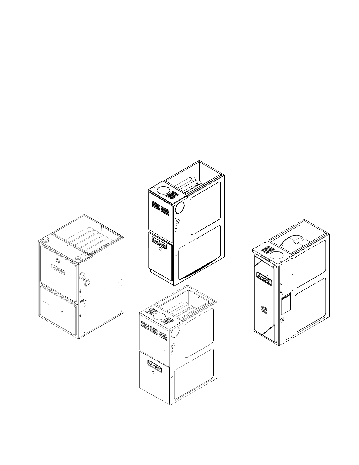
Goodman ACV series, AMV series, AMH series, ADS series, AMS series Service Instructions Manual
...Page 1
Service
Instructions
80%, 90%, 95% Gas Furnaces
& Accessories
ACS, ACV, ADS, ADV, AMH, AMS, AMV, DCS, DDS,
DHS, DMS, GCH, GCS, GDH, GDS, GCV, GHS, GKS,
GME, GMH, GMS, GMV
This manual is to be used by qualified, professionally trained HVAC technicians only. Goodman does
not assume any responsibility for property damage or personal injury due to improper service
procedures or services performed by an unqualified person.
Copyright © 2006-2007 Goodman Manufacturing Company, L.P.
RS6610004 Rev. 2
November 2007
www.goodmanmfg.com www.amana-hac.com
Page 2
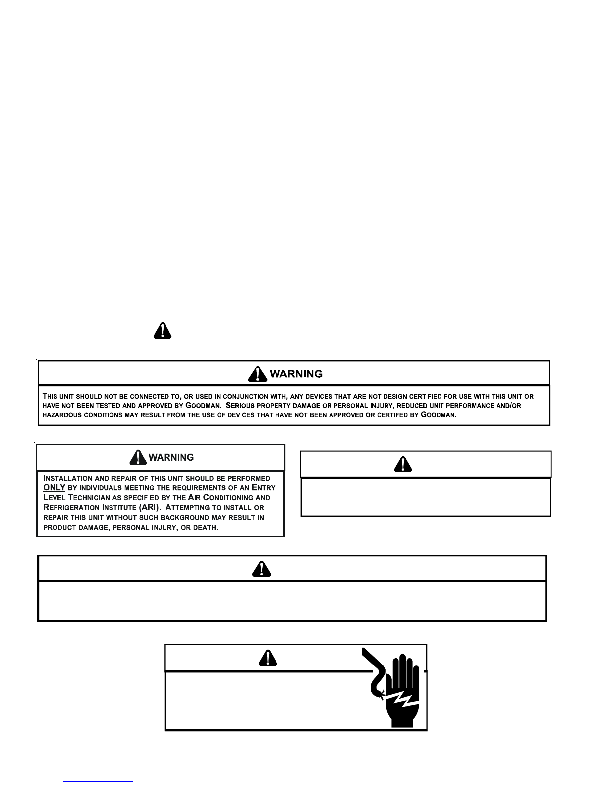
TABLE OF CONTENTS
IMPORTANT INFORMATION ........................... 2-3
PRODUCT IDENTIFICATION ........................ 4-14
OPERATING INSTRUCTIONS .................... 20-22
ACCESSORIES ........................................... 23-27
PRODUCT DESIGN .................................... 28-79
SYSTEM OPERATION ................................ 80-91
POLARIZATION & PHASING ............................. 92
MAINTENANCE ............................................ 93-95
SERVICING .................................................96-128
TROUBLESHOOTING .............................. 105-106
SERVICING TABLE OF CONTENTS ................ 98
ACCESSORIES WIRING DIAGRAMS ......129-131
IMPORTANT INFORMATION
Pride and workmanship go into every product to provide our customers with quality products. It is possible, however,
that during its lifetime a product may require service. Products should be serviced only by a qualified service technician
who is familiar with the safety procedures required in the repair and who is equipped with the proper tools, parts, testing
instruments and the appropriate service manual. REVIEW ALL SERVICE INFORMATION IN THE APPROPRIATE
SERVICE MANUAL BEFORE BEGINNING REPAIRS.
IMPORTANT NOTICES FOR CONSUMERS AND SERVICERS
RECOGNIZE SAFETY SYMBOLS, WORDS AND LABELS
WARNING
T
O PREVENT THE RISK OF PROPERTY DAMAGE, PERSONAL INJURY, OR DEATH,
DO NOT STORE COMBUSTIBLE MATER IALS OR USE GASOLINE OR OTHER
FLAMMABLE LIQUIDS OR VAPORS IN THE VICINITY OF THIS APPLIANCE.
WARNING
GOODMAN WILL NOT BE RESPONSIBLE FOR ANY INJURY OR PROPERTY DAMAGE ARISING FROM IMPROPER SERVICE OR SERVICE PROCEDURES.
IF YOU INSTALL OR PERFORM SERVICE ON THIS UNIT, YOU ASSUME RESPONSIBILITY FOR ANY PERSONAL INJURY OR PROPERTY DAMAGE WHICH
MAY RESULT.
MANY JURISDICTIONS REQUIRE A L ICENSE TO INSTALL O R SERVICE HEATING AND AIR CONDITIONING EQUIPMENT.
WARNING
HIGH VOLTAGE
ISCONNECT ALL POWER BEFORE SERVICING OR
D
INSTALLING THIS UNIT.
BE PRESENT.
DAMAGE, PERSONAL INJURY OR DEATH.
FAILURE TO DO SO MAY CAU SE PROPERTY
MULTIPLE POWER SOURCES MAY
2
Page 3
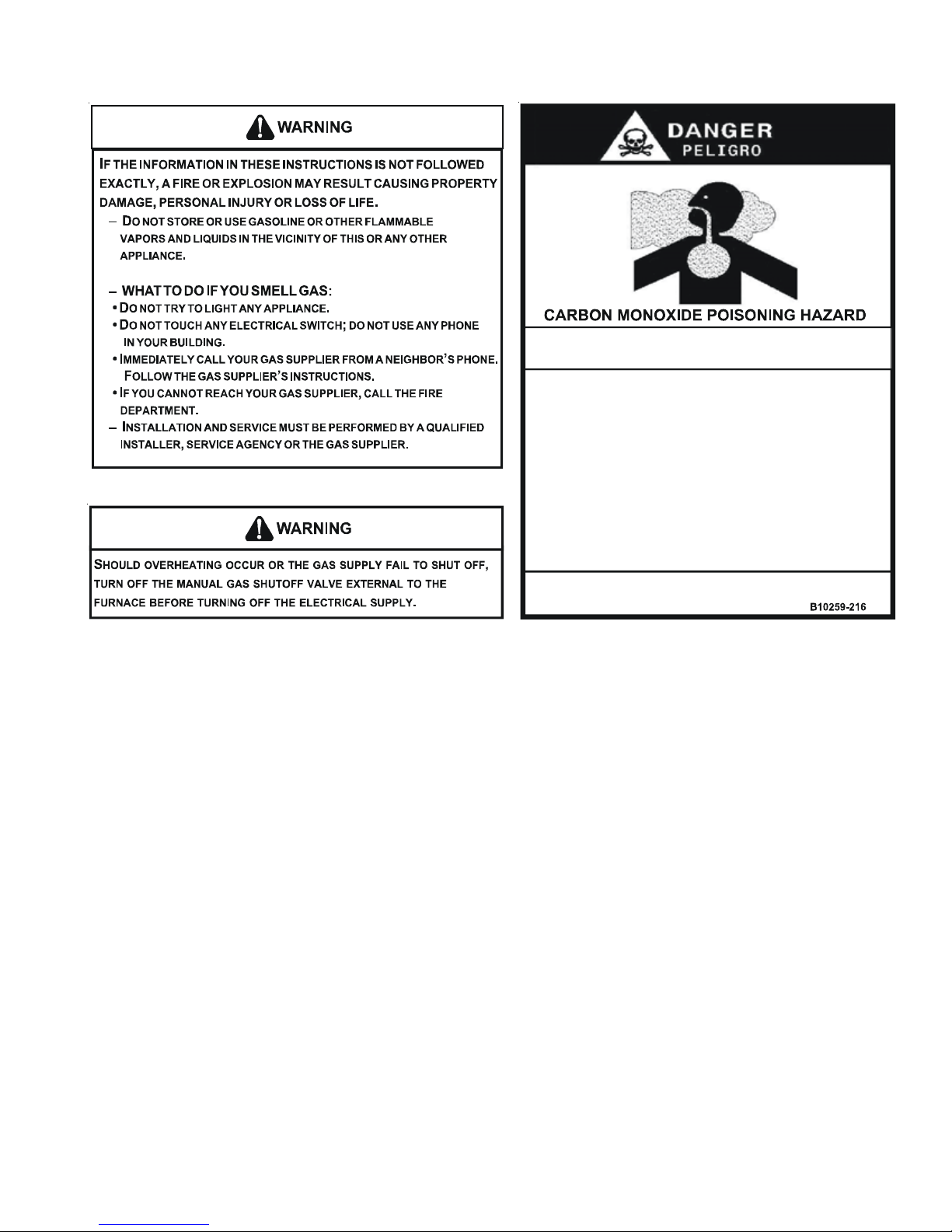
IMPORTANT INFORMATION
Special Warning for In stallation of Furna ce or Air Handling Units in
Enclosed Areas such as Garages, Utility Rooms or Parking Areas
Carbon monoxide producing devices (such as an automobile, space
heater, gas w ater heater, etc.) should not b e operated i n enclosed ar eas
such as unventilated garages, utility rooms or parking areas bec ause of
the danger of carbon monoxide (CO) poisoning resulting from the exhaust
emissions. If a furnace or air handler is installed in an enclosed area such
as a garage, utility ro om or parking area and a carbon monoxid e producing
device is operated therein, there must be adequate, direct outside
ventilation.
This vent ilation is necess ary to avoid the danger of C O poisoning wh ich
can occur if a carbon monoxide producing device continues to operate in
the enclo sed area. Carbon monoxide emis sions can be (re )circulated
througho ut the structure if the furnace or ai r handler is operating in any
mode.
CO can cause serious illness including permanent brain damage or death.
To locate an authorized servicer, please consult your telephone book or the dealer from whom you purchased this
product. For further assistance, please contact:
CONSUMER INFORMATION LINE
GOODMAN® BRAND PRODUCTS
TOLL FREE
1-877-254-4729 (U.S. only)
email us at:
customerservice@goodmanmfg.com
fax us at: (731) 863-2382
(Not a technical assistance line for dealers.)
Outside the U.S., call 1-713-861-2500.
(Not a technical assistance line for dealers.)
Your telephone company will bill you for the call.
Your telephone company will bill you for the call.
CONSUMER INFORMATION LINE
AMANA® BRAND PRODUCTS
TOLL FREE
1-877-254-4729 (U.S. only)
email us at:
hac.consumer.affairs@amanahvac.com
fax us at: (931) 438-4362
(Not a technical assistance line for dealers.)
Outside the U.S., call 1-931-433-6101.
(Not a technical assistance line for dealers.)
3
Page 4
PRODUCT IDENTIFICATION
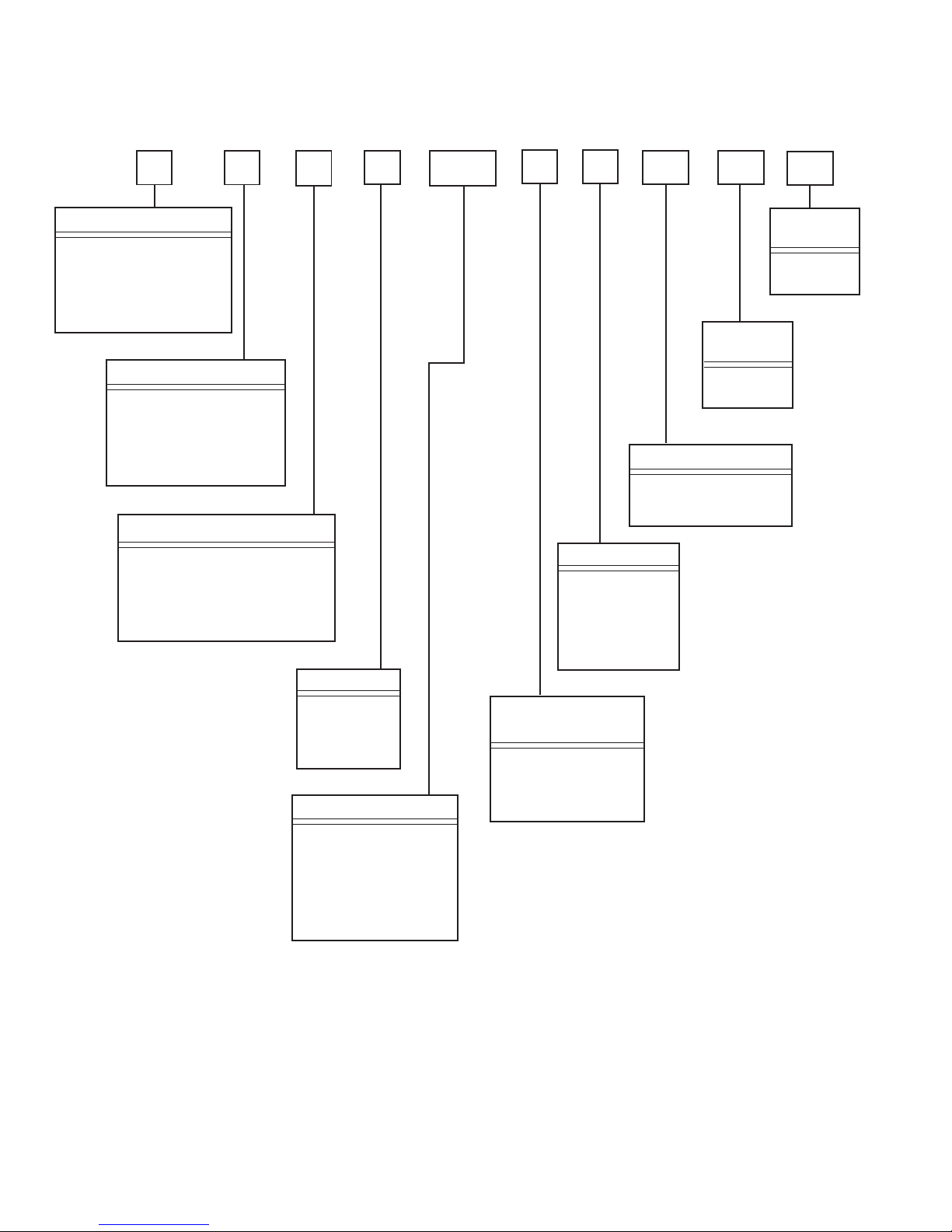
The model and manufacturing number are used for positive identification of component parts used in manufacturing.
Please use these numbers when requesting service or parts information.
G M S 9 070 3 B X A A
Product Type
A: Amana® Brand
D: Amana
Distinctions
G: Goodman
®
TM
Supply Type
M: Upflow/Horizontal
D: Dedicated Downflow
C: Downflow/Horizontal
H: High Air Flow
Furnace Type
E: Two Stage/X-13 Motor
S: Single Stage/Multi-speed
V: Two Stage/Variable-speed
H: Two Stage/Multi-speed
Brand
AFUE
8: 80%
9: 90%
95: 95%
Nominal Input
Minor
Revision
A: Initial
Release
Major
Revision
A: Initial
Release
Additional Features
N: Natural Gas
X: Low NOx
Cabinet Width
A: 14"
B: 17 1/2"
C: 21"
D: 24 1/2"
Airflow Capability
@ 0.5" ESP
3: 1200 CFM
4: 1600 CFM
5: 2000 CFM
045: 45,000 Btuh
070: 70,000 Btuh
090: 90,000 Btuh
115: 115,000 Btuh
140: 140,000 Btuh
4
Page 5
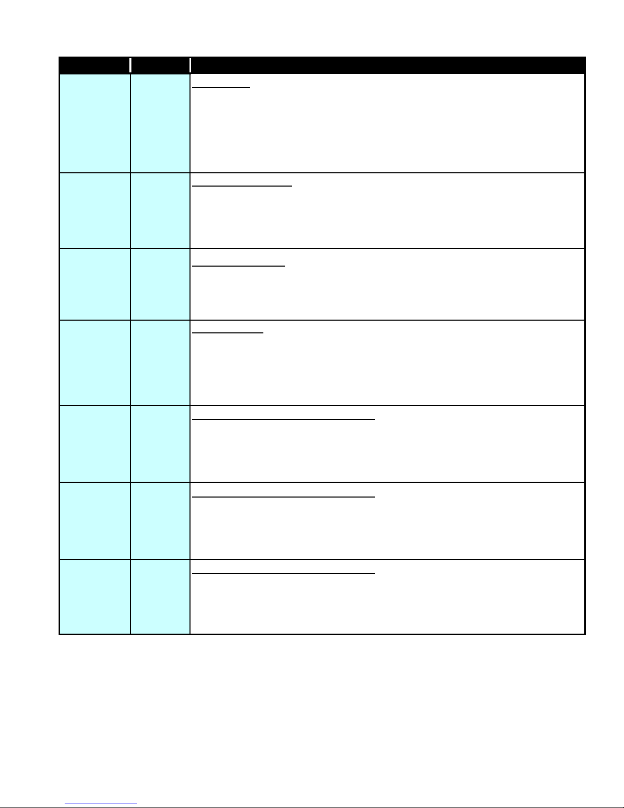
PRODUCT IDENTIFICATION
MODEL # MFG. # 80 % GAS FURNACES
ADS8* ADS8*****AA
Amana® Brand 80% Gas Furnace
changes that include new two tone grey painted cabinet and front panels, PSC motor, standardized blower
decks, and a Surestart Silicon Nitride Igniter. Left or right gas pipe entry.The furnaces also feature an integrated
electronic ignition control and a Million-Air stainless steel tubular heat exchanger. Chassis sizes are now 14",
17.5", 21" wide.
, 39" tall,
Dedicated Downflow
, Induced Draft, 39" 80% furnace redesign
ADV8* ADV8******AA
ADV8*****BA
ADV8*****BA
ADV8*****BB
AMH8*
AMS8* AMS8*****AA
AMV8* AMV8*****AA
AMH8*****AA
AMH8*****AB
AMH8*****AC
AMV8*****BA
AMV8*****BA
AMV8*****BB
Amana® Brand 80% Variable Speed Gas Furnace
2-Stage Induced Draft, new two tone grey painted cabinet and front panels, standardized blower decks and a
Surestart Silicon Nitride Igniter. Left or right gas pipe entry. The furnaces also feature an integrated electronic
ignition control and Million-Air stainless steel tubular heat exchanger. Chassis sizes are now 17.5", 21" wide.
Amana® Brand 80% Variable Speed Gas Furnace
2-Stage Induced Draft, new two tone grey painted cabinet and front panels, standardized blower decks and a
Surestart Silicon Nitride Igniter. Left or right gas pipe entry. The furnaces also feature an integrated electronic
ignition control,
sizes are now 17.5", 21" wide. BB models utilized the round nose inducer motor.
Amana® Brand 80% Gas Furnace
cabinet and front panels, PSC motor, standardized blower decks and a 120V silicon nitride igniter. Left or right
gas pipe entry. The furnaces also feature an integrated electronic ignition control and aluminized steel tubular
heat exchanger. Chassis sizes are now 14", 17.5" 21, and 24.5" wide. ***AB Models used a round nose
inducer motor. ***AC models revert back to Jakel square nose inducer.
Amana® Brand Gas Furnace
changes that include new two tone grey painted cabinet and front panels, PSC motor, standardized blower
decks and a Surestart Silicon Nitride Igniter. Left or right gas pipe entry. The furnaces also feature an integrated
electronic ignition control and a Million-Air stainless steel tubular heat exchanger. Chassis sizes are now 14",
17.5", 21" and 24.5" wide.
Amana® Brand 80% Variable Speed Gas Furnace
or Right, 2-Stage Induced Draft, new two tone grey painted cabinet and front panels, standardized blower decks
and a Surestart Silicon Nitride Igniter. Left or right gas pipe entry. The furnaces also feature an integrated
electronic ignition control and Million-Air stainless steel tubular heat exchanger. Chassis sizes are now 17.5",
21" wide.
Amana® Brand 80% Variable Speed Gas Furnace
2-Stage Induced Draft, new two tone grey painted cabinet and front panels, standardized blower decks and a
Surestart Silicon Nitride Igniter. Left or right gas pipe entry. The furnaces also feature an integrated electronic
ignition control,120 volt silicon nitride igniter and Million-Air stainless steel tubular heat exchanger. Chassis
sizes are now 17.5", 21" wide. BB models used the round nose inducer motor.
120 volt silicon nitride igniter
, 39" tall, Upflow/Horizontal Left or Right, Induced Draft, new grey painted
, 39" tall, Upflow/Horizontal Right or Left, Induced Draft, furnace redesign
- 2 stage heat gas furnace, 39" tall, Dedicated Downflow,
- 2 stage heat gas furnace, 39" tall, Dedicated Downflow,
and Million-Air stainless steel tubular heat exchanger. Chassis
- 2 stage heat gas furnace, 39" tall, Upflow/Horizontal Left
- 2 stage heat gas furnace, 39" tall, Dedicated Downflow,
DDS8* DDS8******AA
DHS8* DHS8******AA
DMS8* DMS8******AA
GDH8*
GDS8*
GDH8*****AA
GDH8*****AB
GDH8*****AC
GDS8*****AA
GDS8*****BA
GDS8*****BB
GDS8*****BC
Amana®
redesign changes that include new two tone grey painted cabinet and front panels, PSC motor, standardized
blower decks and a Carbide Mini-Igniter. Left or right gas pipe entry. The furnaces also feature an integrated
electronic ignition control and aluminized steel tubular heat exchanger. Chassis sizes are now 14", 17.5" and
21" wide.
Amana® Distinctions™ Brand 80% Gas Furnace
design), Induced Draft, furnace design changes that include new two tone grey painted cabinet and front
panels, PSC motor, standardized blower decks and a Carbide Mini-Igniter. Left or right gas pipe entry. The
furnaces also feature an integrated electronic ignition control and aluminized steel tubular heat exchanger.
Chassis sizes are now 14", 17.5", 21" wide.
Amana® Distinctions™ Brand 80% Gas Furnace
furnace design changes that include new two tone grey painted cabinet and front panels, PSC motor,
standardized blower decks and a Carbide Mini-Igniter. Left or right gas pipe entry. The furnaces also feature an
integrated electronic ignition control and aluminized steel tubular heat exchanger. Chassis sizes are now 14",
17.5", 21" and 24.5" wide.
Goodman® Brand 80% Gas Furnace
and front panels, PSC motor, standardized blower decks and a 120V Silicon Nitride igniter. Left or right gas
pipe entry. The furnaces also feature an integrated electronic ignition control and aluminized steel tubular heat
exchanger. Chassis sizes are now 14", 17.5" and 21" wide. ***AB Models used a round nose inducer motor.
***AC models revert back to Jakel square nose inducer.
Goodman® Brand 80% Gas Furnace
new grey painted cabinet and front panels, PSC motor, standardized blower decks and a Carbide Mini-Igniter.
Left or right gas pipe entry. The furnaces also feature an integrated electronic ignition control and aluminized
steel tubular heat exchanger. Chassis sizes are now 14", 17.5", 21" wide. ***BB Models used a round nose
inducer motor. ***BC models revert back to Jakel square nose inducer.
Distinctions™ Brand 80% Gas Furnace
, 39" tall,
Dedicated Downflow
, 39" tall, Dedicated Downflow, 2-stage/multi-speed, Induced Draft,
, 39" tall,
, 39" tall, Upflow/Horizontal Left or Right, Induced Draft,
Dedicated Downflow
, 39" tall, Upflow/Horizontal Left or Right, (High Air Flow
, Induced Draft, new grey painted cabinet
, Induced Draft, furnace
5
Page 6
PRODUCT IDENTIFICATION
MODEL # MFG. # 80 % GAS FURNACES
GHS8*
GME8*
GMH8*
GMS8*
GMV8*
GHS8*****AA
GHS8*****BA
GHS8*****BB
GHS8*****BC
GHS8*****BD
GME8*****AA
GME8*****AB
GME8*****AC
GMH8*****AA
GMH8*****AB
GMH8*****AC
GMS8*****AA
GMS8*****BA
GMS8*****BB
GMS8*****BC
GMS8*****BD
GMV8*****AA
GMV8*****BA
Goodman® Brand 80% Gas Furnace
Induced Draft, new grey painted cabinet and front panels, PSC motor, standardized blower decks and a
Carbide Mini-Igniter. Left or right gas pipe entry. The furnaces also feature an integrated electronic ignition
control and aluminized steel tubular heat exchanger. Chassis sizes are now 14", 17.5", 21" wide. ***BB Models
used a round nose inducer motor. ***BC models revert back to Jakel square nose inducer.
Goodman® Brand
cabinet and front panels, X-13 motor, standardized blower decks and a 120V silicon nitride igniter.. Left or right
gas pipe entry. The furnaces also feature an integrated electronic ignition control and aluminized steel tubular
heat exchanger. Chassis sizes are now 17.5" and 21" wide. ***AB Models used a round nose inducer motor.
***AC models revert back to Jakel square nose inducer.
Goodman® Brand 80% Gas Furnace
painted cabinet and front panels, PSC motor, standardized blower decks and a 120V silicon nitride igniter. Left
or right gas pipe entry. The furnaces also feature an integrated electronic ignition control and aluminized steel
tubular heat exchanger. Chassis sizes are now 14", 17.5" and 21" wide. ***AB Models used a round nose
inducer motor. ***AC models revert back to Jakel square nose inducer.
Goodman® Brand 80% Gas Furnace
painted cabinet and front panels, PSC motor, standardized blower decks and a Carbide Mini-Igniter. Left or
right gas pipe entry. The furnaces also feature an integrated electronic ignition control and aluminized steel
tubular heat exchanger. Chassis sizes are now 14", 17.5", 21" and 24.5" wide. ***BB Models used a round
nose inducer motor. ***BC models revert back to Jakel square nose inducer.
Goodman® Brand 80% Variable Speed
2-stage Induced Draft, new grey painted cabinet and front panels, standardized blower decks and a 120V
Silicon NitrideIgnitor. Left or right gas pipe entry. The furnaces also feature an integrated electronic ignition
control and aluminized steel tubular heat exchanger. Chassis sizes of 17.5", 21" wide.
80% Gas Furnace
, 39" tall, Upflow/Horizontal Left or Right, (High Air Flow Design),
, 39" tall, Upflow/Horizontal Left or Right, Induced Draft, new grey painted
, 39" tall, Upflow/Horizontal Left or Right, Induced Draft, new grey
, 39" tall, Upflow/Horizontal Left or Right, Induced Draft, new grey
- 2 stage heat Gas Furnace, 39" tall, Upflow/Horizontal Left or Right,
6
Page 7
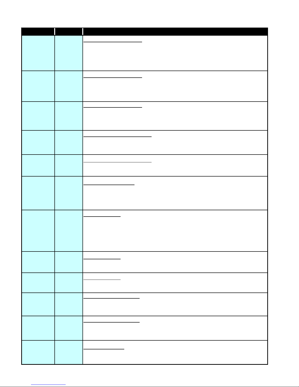
PRODUCT IDENTIFICATION
MODEL # MFG. # DESCRIPTION
ACS9*
ACS9*
ACV9*
ACV9*
P1257001F
through
P1257006F
P1257007F
through
P1257010F
P1257703F,
P1257705F
P1257707F
Amana® Brand 90% Gas Furnace
new two tone grey painted cabinet and front panels, PSC motor, standardized blower decks and a
Surestart Silicon Nitride Igniter. Left or right gas pipe entry. The furnaces also feature an
integrated electronic ignition control and a Million-Air stainless steel tubular heat exchanger. NOx
Certified. Chassis sizes are now 17.5", 21" and 24.5" wide.
(Note: The "P" numbers to the left include the following design changes.)
new crimped designed blower housing and a new blower deck. The crimped blower housing will
not fit inside of the previous "P" numbers for this same model. Redesigned 90° drain elbow by
adding a side drain port hole. The side port drain tube is only used when placing the furnace in
the horizontal left application.
Amana® Brand 90% Variable Speed
Right, 40" tall, 2-stage Induced Draft, new two tone grey painted cabinet and front panels,
standardized blower decks and a Surestart Silicon Nitride Igniter. Left or right gas pipe entry. The
furnaces also feature an integrated electronic ignition control and a Million-Air stainless steel
tubular heat exchanger. NOx Certified. Chassis sizes are now 21" and 24.5" wide.
(Note: The "P" numbers to the left include the following design changes.)
new crimped designed blower housing and a new blower deck. The crimped blower housing will
not fit inside of the previous "P" numbers for this same model. We also have a new drain elbow
with a side drain port hole added. It is used when placing the furnace in the horizontal left
application.
, Downflow/Horizontal Left and Right, 40" tall, Induced Draft,
, Downflow/Horizontal Left and Right, 40" tall, Induced Draft,
Incorporates a
- 2 stage Gas Furnace, Downflow/Horizontal Left and
- 2 stage Gas Furnace, Downflow/Horizontal Left and
Incorporates a
AMS9*
AMS9*
P1256601F
P1256606F
P1256607F
through
P1256610F
Amana® Brand 90% Gas Furnace
two tone grey painted cabinet and front panels, standardized blower decks and a Surestart Silicon
Nitride Igniter. Left or right gas pipe entry. The furnaces also feature an integrated electronic
ignition control and a Million-Air stainless steel tubular heat exchanger. NOx Certified. Chassis
sizes are now 17.5", 21" and 24.5" wide.
(Note: The "P" numbers to the left include the following design changes.)
new crimped designed blower housing and a new blower deck. The crimped blower housing will
fit inside of the previous "P" numbers for this same model. Redesigned 90° drain elbow by
not
adding a side drain port hole. The side port drain tube is only used when placing the furnace in
the horizontal left application.
, Upflow/Horizontal Left and Right, 40" tall, Induced Draft, new
, Upflow/Horizontal Left and Right, 40" tall, Induced Draft, new
Incorporates a
7
Page 8
PRODUCT IDENTIFICATION
MODEL # MFG. # DESCRIPTION
Amana® Brand 95% Gas Furnace, Upflow/Horizontal Left or Right, 40" tall, Induced Draft, new
two tone grey painted cabinet and front panels, standardized blower decks and a 120V Silicon
Nitride Igniter. Left or right gas pipe entry. The furnaces also feature an integrated electronic
ignition control and a Million-Air stainless steel tubular heat exchanger. NOx Certified. Chassis
sizes are now 17.5", 21" and 24.5" wide. Two stage heat, single stage cooling.
Amana® Brand 95% Gas Furnace, Upflow/Horizontal Left and Right, 40" tall, Induced Draft, new
two tone grey painted cabinet and front panels, standardized blower decks and a Surestart Silicon
Nitride Igniter. Left or right gas pipe entry. The furnaces also feature an integrated electronic
ignition control and a Million-Air stainless steel tubular heat exchanger. NOx Certified. Chassis
sizes are now 17.5", 21" and 24.5" wide.
AMH95
AMS95
AMH95***AA
AMH95***AB
AMH95***AC
AMS95***AA
AMS95***AB
AMV9*
AMV9*
P1257401F,
P1257403F,
P1257405F
through
P1257406F
P1257407F,
P1257408F
Amana® Brand 90% Variable Speed - 2 stage Gas Furnace, Upflow/Horizontal Left and Right,
40" tall, 2-stage Induced Draft, furnace redesign changes that include new two tone grey painted
cabinet and front panels, standardized blower decks and a Surestart Silicon Nitride Igniter. Left or
right gas pipe entry. The furnaces also feature an integrated electronic ignition control and a
Million-Air stainless steel tubular heat exchanger. NOx Certified. Chassis sizes are now 17.5", 21"
and 24.5" wide.
(Note: The "P" numbers to the left include the following design changes.) Incorporates a
new crimped designed blower housing and a new blower deck. The crimped blower housing will
not fit inside of the previous "P" numbers for this same model. Redesigned 90° drain elbow by
adding a side drain port hole. The side port drain tube is only used when placing the furnace in
the horizontal left application.
8
Page 9
PRODUCT IDENTIFICATION
MODEL # MFG. # DESCRIPTION
Amana® Distinctions™ Brand 90% Gas Furnace, Downflow/Horizontal Left and Right, 40" tall,
Induced Draft, furnace design changes that include new two tone grey painted cabinet and front
panels, PSC motor, standardized blower decks and a Carbide Mini-Igniter. Left or right gas pipe
entry. The furnaces also feature an integrated electronic ignition control and aluminized steel
tubular heat exchanger. NOx Certified. Chassis sizes are now 17.5", 21" and 24.5" wide.
(Note: The "P" numbers to the left include the following design changes.) Incorporates a
new crimped designed blower housing and a new blower deck. The crimped blower housing will
not fit inside of the previous "P" numbers for this same model. Redesigned 90° drain elbow by
adding a side drain port hole. The side port drain tube is only used when placing the furnace in
the horizontal left application.
Amana® Distinctions™ Brand 90% Gas Furnace, Upflow/Horizontal Left or Right, 40" tall,
Induced Draft, furnace design changes that include new two tone grey painted cabinet and front
panels, PSC motor, standardized blower decks and a Carbide Mini-Igniter. Left or right gas pipe
entry. The furnaces also feature an integrated electronic ignition control and aluminized steel
tubular heat exchanger. NOx Certified. Chassis sizes are now 17.5", 21" and 24.5" wide.
DCS9*
DCS9*
DMS9*
P1257102F,
P1257104F,
P1257106F
P1257107F
P1257108F
P1256701F,
P1256706F
DMS9*
P1256707F
through
P1256710F
Amana® Distinctions™ Brand 90% Gas Furnace, Upflow/Horizontal Left or Right, 40" tall,
Induced Draft, furnace design changes that include new two tone grey painted cabinet and front
panels, PSC motor, standardized blower decks and a Carbide Mini-Igniter. Left or right gas pipe
entry. The furnaces also feature an integrated electronic ignition control and aluminized steel
tubular heat exchanger. NOx Certified. Chassis sizes are now 17.5", 21" and 24.5" wide.
(Note: The "P" numbers to the left include the following design changes.) Incorporates a
new crimped designed blower housing and a new blower deck. The crimped blower housing will
not fit inside of the previous "P" numbers for this same model. Redesigned 90° drain elbow by
adding a side drain port hole. The side port drain tube is only used when placing the furnace in
the horizontal left application.
9
Page 10
PRODUCT IDENTIFICATION
MODEL # MFG. # DESCRIPTION
GCS9*
P1257201F,
P1257202F
P1257204F,
P1257206F
Goodman® Brand 90% Gas Furnace,
new grey painted cabinet and front panels, PSC motor, standardized blower decks and a Carbide
Mini-Igniter. Left or right gas pipe entry. The furnaces also feature an integrated electronic ignition
control and aluminized steel tubular heat exchanger. NOx Certified. Chassis sizes are now 17.5",
21" and 24.5" wide.
Downflow/Horizontal Left and Right, 40" tall, Induced Draft,
GCS9*
GCH9*
GCV9*
GKS9*
P1257207F
through
P1257209F
GCH9***AA
GCH9***AB
P1257803F,
P1257805F
GKS9****AA
GKS9****AB
GKS9****AC
Goodman® Brand 90% Gas Furnace,
Downflow/Horizontal Left and Right, 40" tall, Induced Draft,
new grey painted cabinet and front panels, PSC motor, standardized blower decks and a Carbide
Mini-Igniter. Left or right gas pipe entry. The furnaces also feature an integrated electronic ignition
control and aluminized steel tubular heat exchanger. NOx Certified. Chassis sizes are now 17.5",
21" and 24.5" wide.
(Note: The "P" numbers to the left include the following design changes.) Incorporates a new
crimped designed blower housing and a new blower deck. The crimped blower housing will not fit
inside of the previous "P" numbers for this same model. Redesigned 90° drain elbow by adding a
side drain port hole. The side port drain tube is only used when placing the furnace in the horizontal
left application.
Goodman® Brand 90% Gas Furnace,
Downflow/Horizontal Left and Right, 40" tall, Induced Draft,
new grey painted cabinet and front panels, PSC motor, standardized blower decks and a 120V
Silicon Nitride igniter. Left or right gas pipe entry. The furnaces also feature an integrated electronic
ignition control and aluminized steel tubular heat exchanger. NOx Certified. Chassis sie are now
17.5", 21" and 24.5" wide. Two stage heat, single stage cooling.
Goodman® Brand 90% Variable Speed
- 2 Stage Gas Furnace, 40" tall, Upflow/Horizontal Left or
Right, Induced Draft, new grey painted cabinet and front panels, standardized blower decks and a
Carbide Mini-Igniter. Left or right gas pipe entry. The furnaces also feature an integrated electronic
ignition control and aluminized steel tubular heat exchanger. NOx Certified. Chassis sizes are now
21" and 24.5" wide. (BA models use Surestat Silicon Nitride igniters.)
Goodman® Brand 92.1% Gas Furnace
, Upflow/Horizontal Left or Right, 40" tall, Induced Draft,
new grey painted cabinet and front panels, PSC motor, standardized blower decks and a Carbide
Mini-Igniter. Left or right gas pipe entry. The furnaces also feature an integrated electronic ignition
control and aluminized steel tubular heat exchanger. NOx Certified. Chassis sizes are now 17.5",
21" and 24.5" wide.
GMS9*
GMS9*
GMS95*
GMV9*
P1256801F
through
P1256802F
P1256804F,
P1256806F
P1256807F
through
P1256809F
GMS9****AA
GMS9****AB
P1257603F -
P1257607F
Goodman® Brand 90% Gas Furnace, Upflow/Horizontal Left or Right, 40" tall, Induced Draft, new
grey painted cabinet and front panels, PSC motor, standardized blower decks and a Carbide MiniIgniter. Left or right gas pipe entry. The furnaces also feature an integrated electronic ignition control
and aluminized steel tubular heat exchanger. NOx Certified. Chassis sizes are now 17.5", 21" and
24.5" wide.
Goodman® Brand 90% Gas Furnace
, Upflow/Horizontal Left or Right, 40" tall, Induced Draft, new
grey painted cabinet and front panels, PSC motor, standardized blower decks and a Carbide MiniIgniter. Left or right gas pipe entry. The furnaces also feature an integrated electronic ignition control
and aluminized steel tubular heat exchanger. NOx Certified. Chassis sizes are now 17.5", 21" and
24.5" wide.
Note: The "P" numbers to the left include the following design changes.
(
) Incorporates a new
crimped designed blower housing and a new blower deck. The crimped blower housing will not fit
inside of the previous "P" numbers for this same model. Redesigned 90° drain elbow by adding a
side drain port hole. The side port drain tube is only used when placing the furnace in the horizontal
left application.
Goodman® Brand 95% Gas Furnace
, Upflow/Horizontal Left or Right, 40" tall, Induced Draft, new
grey painted cabinet and front panels, PSC motor, standardized blower decks and a Carbide MiniIgniter. Left or right gas pipe entry. The furnaces also feature an integrated electronic ignition control
and aluminized steel tubular heat exchanger. NOx Certified. Chassis sizes are now 17.5", 21" and
24.5" wide.
Goodman® Brand 90% Variable Speed
- 2 stage heat Gas Furnace, Upflow/Horizontal Left or
Right, 40" tall, 2-stage Induced Draft, new grey painted cabinet and front panels, standardized
blower decks and a Carbide Mini-Igniter. Left or right gas pipe entry. The furnaces also feature an
integrated electronic ignition control and aluminized steel tubular heat exchanger. NOx Certified.
Chassis sizes of 17.5", 21" and 24.5" wide.
10
Page 11
PRODUCT IDENTIFICATION
MODEL # MFG. # DESCRIPTION
GMV9*
GMH95*
GMV95*
P1257610F -
P1257611F
GMH95***AA
GMH95***AB
GMH95***AC
GMV95***AA
GMV95***AB
GMV95***BA
GMV95***BB
Goodman® Brand 90% Variable Speed
Right, 40" tall, 2-stage Induced Draft, new grey painted cabinet and front panels, standardized
blower decks and a Carbide Mini-Igniter. Left or right gas pipe entry. The furnaces also feature an
integrated electronic ignition control and aluminized steel tubular heat exchanger. NOx Certified.
Chassis sizes of 17.5", 21" and 24.5" wide.
(Note: The "P" numbers to the left include the following design changes.)
crimped designed blower housing and a new blower deck. The crimped blower housing will not fit
inside of the previous "P" numbers for this same model. Redesigned 90° drain elbow by adding a
side drain port hole. The side port drain tube is only used when placing the furnace in the horizontal
left application.
Goodman® Brand 95% Gas Furnace, Upflow/Horizontal Left or Right, 40" tall, Induced Draft, new
two tone grey painted cabinet and front panels, standardized blower decks and a 120V Silicon
Nitride Igniter. Left or right gas pipe entry. The furnaces also feature an integrated electronic ignition
control and a Million-Air stainless steel tubular heat exchanger. NOx Certified. Chassis sizes are
now 17.5", 21" and 24.5" wide. Two stage heat, single stage cooling.
Goodman® Brand 95% Variable Speed
40" tall, 2-stage Induced Draft, new grey painted cabinet and front panels, new standardized blower
decks, new blower housing and a Carbide Mini-Igniter.(BA model has 120V Silicon Nitride igniters.)
Left or right gas pipe entry. The furnaces also feature an integrated electronic ignition control and
aluminized steel tubular heat exchanger. NOx Certified. Chassis sizes are now 17.5", 21" and 24.5"
wide.
- 2 stage heat Gas Furnace, Upflow/Horizontal Left or
Incorporates a new
- 2 stage Gas Furnace, Upflow/Horizontal Left or Right,
11
Page 12
PRODUCT IDENTIFICATION
MODEL # MFG # DESCRIPTION
Fossil Fuel Kit. The AFE18-60A control is designed for use where the indoor coil is located
above/downstream of a gas or fossil fuel furnace when used with a heat pump. It will operate
AFE18-60A
N/A
with single and two stage heat pumps and single and two stage furnaces. The AFE18-60A
control will turn the heat pump unit off when the furnace is turned on. An anti-short cycle feature
initiates a 3 minute timed off delay when the compressor goes off.
AMU1620
AMU1625
AMU2020
AMU2025
GMU1620
GMU1625
GMU2020
GMU2025
ASAS-10
ASAS-11
ASAS-12
ASAS-18
CFB17
CFB21
CFB24
DCVK-20
DCVK-30
P1251305F
P1251306F
P1251307F
P1251308F
N/A
P1251301F
P1251302F
P1251303F
P1251304F
P1228004F
P1228005F
P1228003F
P1254001F
P1254002F
Media Air Cleaner. For use with current architectural grey Goodman® and Amana® Brand 80%
and 90% variable speed furnace models. The Amana (AMU*) and Goodman (GMU*) Media Air
Cleaner is a high efficiency air filtration device designed to remove dirt, dust, pollen and other
microscopic particles from the air passing through it. Flexible performance range up to 2,000
CFM capacity. The air cleaner should be installed in the system so that all the system air is
circulated through the air cleaner. The air cleaner will only remove the airborne contaminants
delivered to it. Maximum performance is obtained when the system blower is set for continuous
operation. Carbon filters (optional) are available.
Electronic Air Cleaner. For use with current architectural grey Goodman® and Amana® Brand
80% and 90% variable speed furnace models. The High-Efficiency Electronic Air Cleaner is
designed to remove air contaminants down to .01 microns. Carbon filters (optional) remove
odors. Dual indicator lights show unit operation at a glance. Electronic proving switch cycles the
air cleaner On/Off with the system fan. Durable powder-coat paint finish resists corrosion.
Downflow Subbase Kit. For use with select Goodman®, Amana® Brand & Amana®
Distinctions™ Brand furnace models ACS9, ACV9, DCS9, GCH9, GCS9, GCV9. These kits are
available for the following furnace widths: 17.5" wide (CFB17), 21" wide (CFB21) and 24" wide
(CFB24). The kits must be used to prevent excessive temperature from reaching combustible
materials, if the furnace is installed on a combustible floor. This subbase effectively separated
the furnace base and plenum from combustible materials. To ensure safe installation, do not
install the counterflow floor base directly on carpeting, tile, or other combustible material other
than wood flooring.
Concentric Vent Kit. For use with Amana® Brand furnace models ACS9, AMS9, AMS95,
ACV9, AMV9, AMH95, DCS9, DMS9, GCS9, GMS9, GMS95,GCH9, GKS9, GCV9,
GMV9,GMH95, GMV95. This kit is designed to allow terminations of a direct vent furnace to be
"concentrically" vented through a wall or roof. This kit allows a single penetration to support
terminations for both the vent/flue and the combustion air intake pipe. The DCVK-20 (2") and
DCVK-30 (3") kits are certified for models listed above. See specification sheets on future
models for use of the vent kit.
Side Wall Only Concentric Vent Kit. For use with 90% furnace models ACS9, AMS9, ACV9,
0170K00000S
N/A
AMV9, AMH95, DCS9, DMS9, GCH9, GCS9, GKS9, GMS9, GCV9, GMH95, GMV9, GMV95.
This kit is to be used with 2" or 3" vent systems. The vent kit must terminate outside the
structure. This kit is NOT intended for use with single pipe (indirect vent) installations.
12
Page 13
PRODUCT IDENTIFICATION
MODEL # MFG # DESCRIPTION
Dehumidistat. For use with Goodman® and Amana® Brand two-stage variable speed furnace
models ADV8, AMV8, ACV9, AMV9, GMV8, GCV9, GMV9, GMV95. Wall mounted, 24 volt
humidity control available as a Dehumidistat used to reduce the airflow in the air conditioning
DEHUM1
EFR01
FTK03A
HA02
P1227801F
P1221001
P1221002F
P1171304F
P1171305F
P1129112F
mode when necessary to lower the humidity in an occupied home to prevent dew build-up
associated with high humidity levels. This control features a moisture-sensitive nylon element
and also provides positive ON-OFF settings for manual operation. The control is a normally
closed switch that opens on humidity rise causing the blower to switch to a lower speed to
control the humidity within the structure.
External Filter Rack Kit. For use with Goodman® and Amana® Brand 90% upflow variable
speed gas furnace models AMH95, AMS9, AMS95, GMH95, GMS9, GMS95, DMS9, AMV9,
GMV9, GMV95. This kit is intended to provide a location, external to the furnace casing, for
installation of a permanent filter. The rack is mounted over the indoor air blower compartment
area of either side panel, and provide filter retention as well as a location for attaching return air
ductwork.
Furnace Twinning Kit. This kit allows Goodman® or Amana® Brand single stage 80% and
single stage 90% gas furnaces to operate at the same time from a single thermostat. The two
furnaces to be "twinned" must be the exact same model with their circulating air blowers set to
deliver the same air flow at the same time. The furnaces may deliver different CFM's in the
cooling mode, if applicable. This kit cannot be used to control more than two furnaces.
High Altitude Kit. The kit is designed to convert Goodman®, Amana® Brand & Amana®
Distinctions™ Brand 80% gas furnace models (AMH8*, AMS8*, ADS8*, DMS8*, DDS8*, DHS8*,
GDS8*, GMH8*, GMS8*, GDS8*, GHS8*) for higher altitudes. This kit is required when installing
these furnaces above their maximum rated altitude. This kit contains
# 43-49, 55-58 gas orifices. The orifices in the kit have been selected as a result of testing with
the American Gas Association. They will provide appropriate derating at the altitude listed in the
High Altitude Charts as shown in the installation instructions of the kit.
HALP10
HALP11
HALP13
P1129112F
P1129113F
P1129112F
High Altitude Propane Gas Conversion Kit. Used on Goodman® and Amana® Brand 90%
single stage (ACS9, AMS9, DCS9, DMS9, GCS9, GMS9) furnace models. This kit is required
when installing furnaces above their maximum rated altitude. This kit contains propane gas
orifices. The orifices in the kit have been selected as a result of testing with the American Gas
Association. They will provide appropriate derating at the altitude listed in the High Altitude
Charts as shown in the installation instructions of the kit.
High Altitude Propane Gas Conversion Kit. Used on Goodman® and Amana® Brand 90%
single stage (ACV9, AMV9, GCV9, GMV9, GMV95) furnace models. This kit is required when
installing furnaces above their maximum rated altitude. This kit contains propane gas orifices.
The orifices in the kit have been selected as a result of testing with the American Gas
Association. They will provide appropriate derating at the altitude listed in the High Altitude
Charts as shown in the installation instructions of the kit.
High Altitude Propane Gas Conversion Kit. Used on Goodman® and Amana® Brand 90% two
stage (ACV9, GCV9) furnace models. This kit is required when installing furnaces above their
maximum rated altitude. This kit contains propane gas orifices. The orifices in the kit have been
selected as a result of testing with the American Gas Association. They will provide appropriate
derating at the altitude listed in the High Altitude Charts as shown in the installation instructions
of the kit.
13
Page 14
PRODUCT IDENTIFICATION
MODEL # MFG # DESCRIPTION
HANG11-12
P1210305F
P1210306F
High Altitude Natural Gas Kit
models
ACS9, AMS9, DCS9, DMS9, GCS9
the furnaces above their maximum rated altitude. This kit contains natural gas orifices. The
orifices in the kit have been selected with the American Gas Association. They will provide
appropriate derating at the altitude listed in the High Altitude Charts as shown in the installations
of the kit.
. For use with Goodman® and Amana® Brand 90% furnace
and
GMS9.
These kits are required when installing
HANG13-14
HANG16
HAPS27-29
HAPS31
LPLP01
LPT-00A
P1210307F
P1210308F
P1210310F
P1210518F
through
P1210520F
P1210522F
P1237701F
N/A
High Altitude Natural Gas Kit
models
AMV9, GMV9, GMV95.
. For use with Goodman® and Amana® Brand 90% furnace
These kits are required when installing the furnaces above their
maximum rated altitude. The orifices in the kit have been selected as a result of testing with the
American Gas Association. They will provide appropriate derating at the altitude listed in the
High Altitude Charts as shown in the installations of the kit.
High Altitude Natural Gas Kit
models
ACV9, GCV9.
These kits are required when installing the furnaces above their
. For use with Goodman® and Amana® Brand 90% furnace
maximum rated altitude. The orifices in the kit have been selected as a result of testing with the
American Gas Association. They will provide appropriate derating at the altitude listed in the
High Altitude Charts as shown in the installations of the kit.
High Altitude Pressure Switch Kit
furnace models
AMS9, ACS9, DCS9, DMS9, GSC9, GMS9, AMV9, GMV9 and GMV95.
. For use with selected Goodman® and Amana® Brand 90%
This kit
contains a high altitude pressure switch that must be used at altitudes above the rated altitudes
because of reduced air density.
High Altitude Pressure Switch Kit
furnace models
ACV9, GCV9.
. For use with selected Goodman® and Amana® Brand 90%
This kit contains a high altitude pressure switch that must be
used at altitudes above the rated altitudes because of reduced air density.
LP Gas Low Pressure Kit. Designed for application on Goodman® and Amana® Brand's 90%
single-stage and two-stage gas fired furnace product installed on LP gas listed in this manual.
The kit monitors gas line pressure with a pressure switch and disables the unit's gas valve if the
line pressure drops below acceptable levels. Application of the LPLP kit is aimed at reducing the
occurrence of sooted heat exchangers in product installed on LP gas.
LP Conversion Kit
models
ADS8, AMS8, GDS8, GMS8, DMS8, DDS8, DHS8, GHS8, ACS9, AMS9, AMS95,
DCS9, DMS9, GCS9, GKS9, GMS9 and GMS95.
. For use with Goodman®, Amana® Brand & Amana® Distinctions™ Brand
This kit converts
only
single-stage gas fired
units from natural to propane gas. The conversion from natural gas (as shipped from the factory)
to propane gas requires: replacing the burner orifices, replacing gas valve regulator spring (all
single stage units) and applying identification labels.
NOx screens must be removed when
converting 80% furnaces to this LP kit.
LP Conversion Kit
LPM-03B
N/A
variable speed models. This kit includes the LP gas valve, (1.25mm, # 55 orifices), installation
instructions and a label to show that the furnace has been converted.
LP Conversion Kit
LPM-05
N/A
models using a White-Rodgers 36G54 2-stage gas valve kit. Includes regulator springs, #55
orifices, instructions and a label to show the furnace has been converted to L.P.
Internal Filter Retention Kit.
RF000180
N/A
Distinctions™ Brand 90%
bottom of the furnace and contains enough hardware for (10) furnaces. This kit is NOT to be
used on horizontal applications.
Internal Filter Retention Kit.
RF000181
N/A
Distinctions™ Brand 90%
bottom of the furnace and contains enough hardware for (10) furnaces. This kit is NOT to be
used on horizontal applications.
SBT14
SBT17
SBT21
SBT24
N/A
Downflow Subbase.
furnace models
furnace widths: 14" wide (SBT14) 17.5" wide (SBT17), 21" wide (SBT21) and 24" wide (SBT24).
14
. For use with Goodman® and Amana® Brand 80% and 90% 2-stage
. For use with Goodman® and Amana® Brand 2-stage variable speed
For use with Goodman®, Amana® Brand & Amana®
upflow only
furnaces. This kit allows a filter to be installed in the
For use with Goodman®, Amana® Brand and Amana®
counterflow only
furnaces. This kit allows a filter to be installed in the
For use with Goodman® and Amana® Brand 80% dedicated downflow
ADV8, ADS8, GDS8 and GDH8
. These kits are available for the following
Page 15
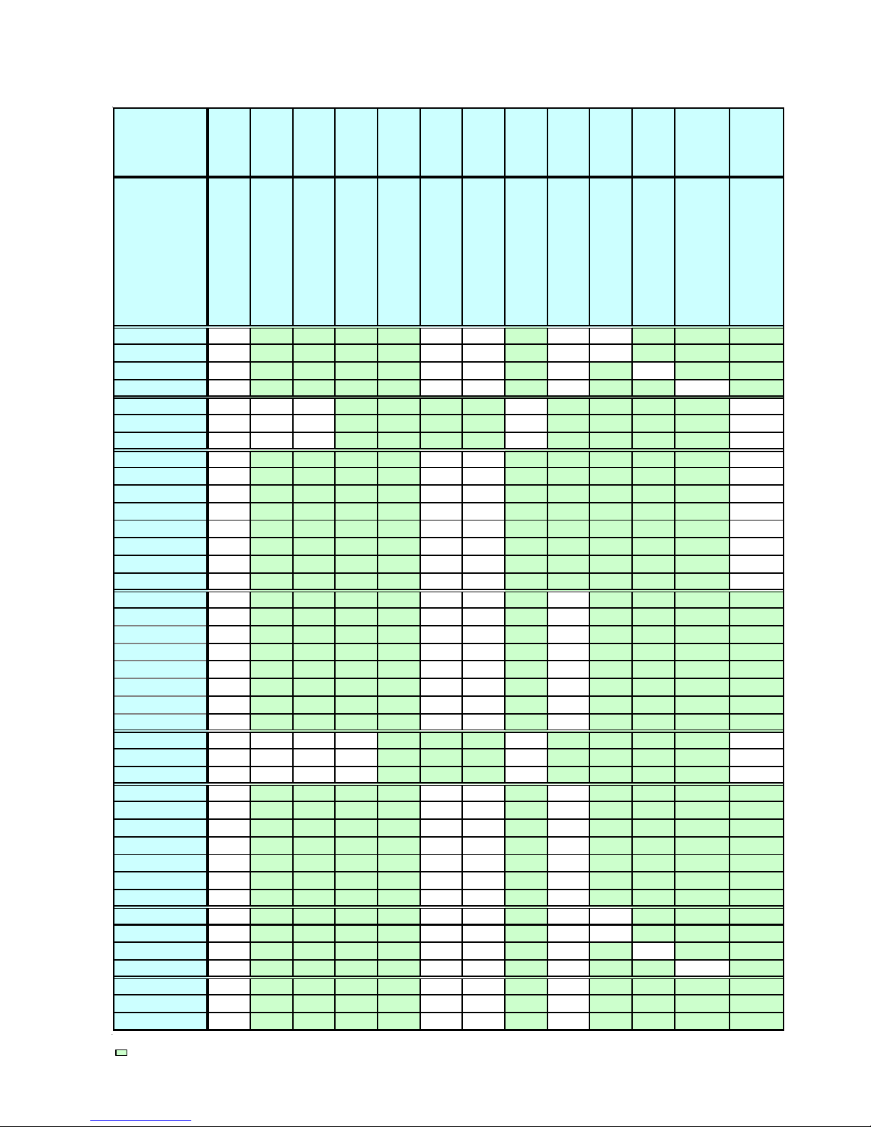
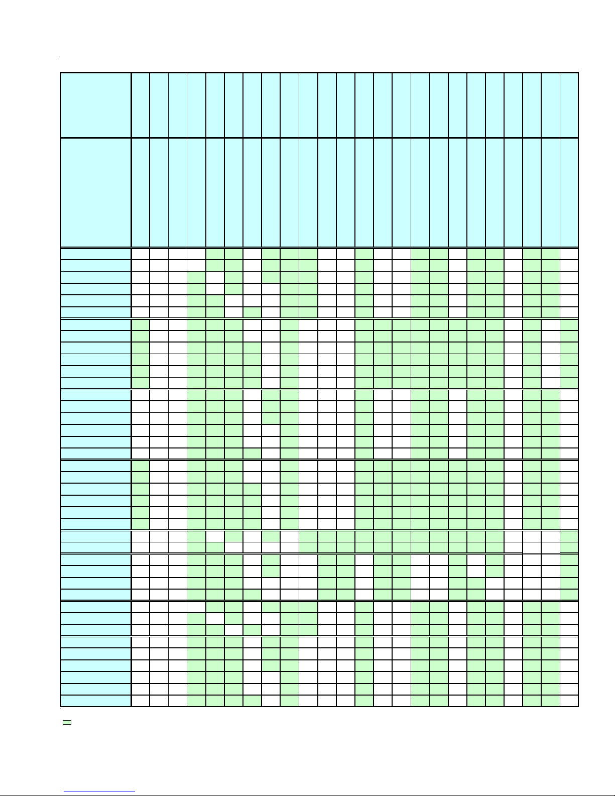
ACCESSORIES
AMANA® BRAND & AMANA® DISTINCTIONS™ BRAND 80% FURNACE ACCESSORIES
Model Number
Description
ADS80453ANA X X X X X
ADS80703ANA X X X X X
ADS80904BNA X X X X X
ADS81155CNA X X X X X
ADV80703BX X X X X X
ADV80905CX X X X X X
ADV81155CX X X X X X
AMH80453ANA X
AMH80703ANA X
AMH80704BNA X
AMH80903BNA X
AMH80904BNA X
AMH80905CNA X
AMH81155CNA X
AMH81405DNA X
AMS80453ANA X X X X
AMS80703ANA X X X X
AMS80704BNA X X X X
AMS80903BNA X X X X
AMS80904BNA X X X X
AMS80905CNA X X X X
AMS81155CNA X X X X
AMS81405DNA X X X X
AMV80704BXA X X X X X X
AMV80905CXA X X X X X X
AMV81155CXA X X X X X X
DMS80453ANA X X X X
DMS80703ANA X X X X
DMS80704BNA X X X X
DMS80904BNA X X X X
DMS80905CNA X X X X
DMS81155CNA X X X X
DMS81405DNA X X X X
DDS80453AXA X X X X X
DDS80703AXA X X X X X
DDS80904BXA X X X X X
DDS81155CXA X X X X X
DHS80453AXA X X X X
DHS80704BXA X X X X
DHS80905CXA X X X X
X - Available for this model (1) Up to 7,000 ft. (2) 7,001 to 11,000 ft. (3) 7,001 to 9,000 ft.
Not used in this application. (4) 9,001 to 11,000 ft. (5) MUST use single stage thermostat with FTK03A
Note: All installations above 7,000 ft. require a pressure switch change.
AFE180-60A
Fossil Fuel Kit
AMU
ASAS
Media Air Cleaners
Electronic Air Cleaner
EFR01
DEHUM1
Dehumidistat
FTK03A
External Filter Rack
Furnace Twinning Kit
(5)
(5)
HA02
LPM-03B
Propane Gas Conversion Kit
High Altitude Natural Gas Kit
XX
XX
SBT14
LPT-00A
Propane Gas Conversion Kit
SBT17
Downflow Subbase 14"
Downflow Subbase 17.5"
SBT21
Downflow Subbase 21"
(5) XX
(5) XX
(5)
(5)
(5)
(5)
XX
XX
XX
XX
LPM-05
Propane Gas Conversion Kit
15
Page 16
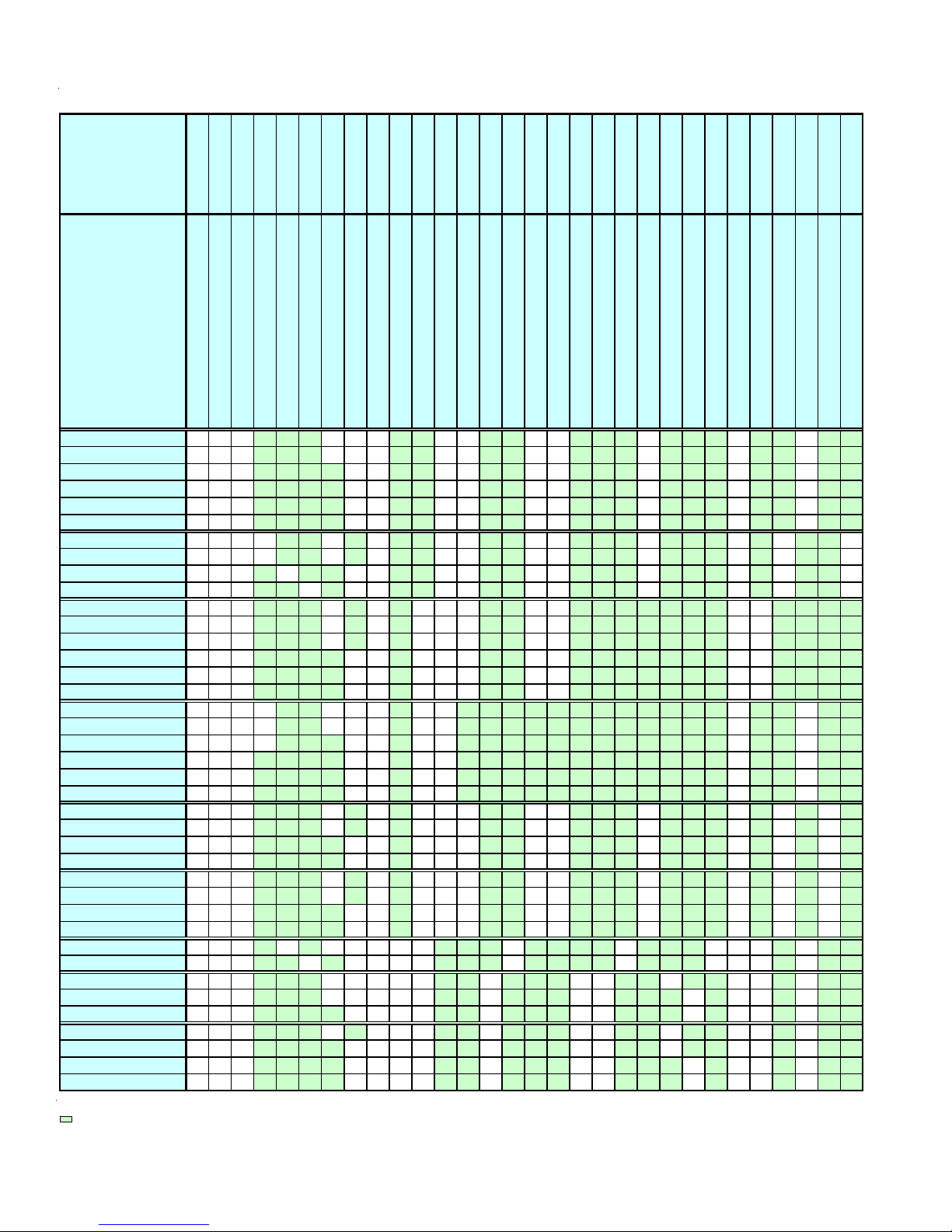
ACCESSORIES
GOODMAN® BRAND 80% FURNACE ACCESSORIES
16
Model Number
Description
GDS80453ANA X X X X X
GDS80703ANA X X X X X
GDS80904BNA X X X X X
GDS81155CNA X X X X X
GDH80453AXA
GDH80703AXA
GDH80904BXA
GDH81155CXA
GHS80453A*A X X X X
GHS80704C*A X X X X
GHS80703B*A X X X X
GME80704BX* X X X X X
GME80905CX* X X X X X
GME81155CX* X X X X X
GMH80453ANA X (5) X X
GMH80453AXA X (5) X X
GMH80703ANA X (5) X X
GMH80703AXA X (5) X X
GMH80704BNA X (5) X X
GMH80704BXA X (5) X X
GMH80903BNA X (5) X X
GMH80904BNA X (5) X X
GMH80904BXA X (5) X X
GMH80905CNA X (5) X X
GMH80905CXA X (5) X X
GMH81155CNA X (5) X X
GMH81155CXA X (5) X X
GMH81405DNA X (5) X X
GMH81405DXA X (5) X X
GMS80453ANA X X X X
GMS80703ANA X X X X
GMS80704BNA X X X X
GMS80903BNA X X X X
GMS80904BNA X X X X
GMS80905CNA X X X
GMS81155CNA X X X
GMS81405DNA X X X
GMV80704BXA X X X X X X
GMV80905CXA X X X X X X
GMV81155CXA X X X X X X
X - Available for this model (1) Up to 7,000 ft. (2) 7,001 to 11,000 ft. (3) 7,001 to 9,000 ft.
Not used in this application. (4) 9,001 to 11,000 ft. (5) MUST use single stage thermostat with FTK03A
Note: All installations above 7,000 ft. require a pressure switch change.
X(5)XXXX
X(5)XXXX
X (5)XXXX
X(5)XXXX
GMU
GSAS
AFE180-60A
Media
Electronic
Air Cleaner
Fossil Fuel Kit
Air Cleaners
EFR01
DEHUM1
Furnace
External
Dehumidistat
Filter Rack
HA02
FTK03A
High Altitud
Twinning Kit
LPM-03B
Propane Gas
Propane Gas
Conversion Kit
Natural Gas Kit
SBT14
SBT17
17.5"
SBT21
21"
Downflow Subbase
LPT-00A
14"
Conversion Kit
Downflow Subbase
Downflow Subbase
LPM-05
Propane Gas
Conversion Kit
Page 17
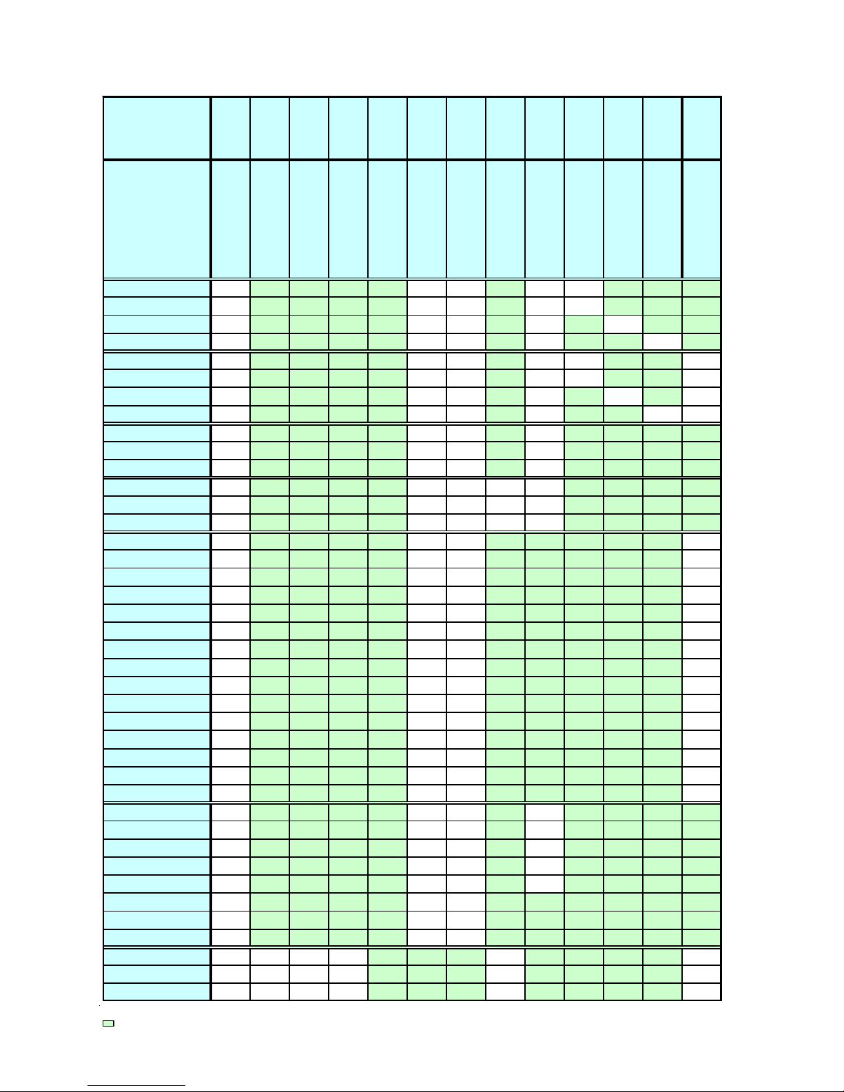
ACCESSORIES
AMANA® BRAND & AMANA® DISTINCTIONS™ BRAND 90% & 95% Furnace Accessories
Model Number
Description
ACS90453BXA X X X X X X
ACS90703BXA X X X X X X
ACS90704CXA X X X X X X
ACS90904CXA X X X X X X X
ACS90905DXA X X X X X X X
ACS91155DXA X X X X X X
AMH950453BXA X X X X X
AMH950703BXA X X X X X
AMH950704CXA X X X X
AMH950904CXA X X X X
AMH950905DXA X X X X
AMH951155DXA X X X X
AMS90453BXA X X X X X X
AMS90703BXA X X X X X X
AMS90704CXA X X X X X X
AMS90904CXA X X X X X X X
AMS90905DXA X X X X X X X
AMS91155DXA X X X X X X
AMS950453BXA X X X X X X
AMS950703BXA X X X X X X
AMS950704CXA X X X X X
AMS950905CXA X X X X X
AMS950905DXA X X X X X
AMS951155DXA X X X X X
ACV90704CXA X X X X X X X X X
ACV90905DXA XXX XXXX XXX
AMV90453BXA X X X X X X
AMV90704CXA X X X X X X
AMV90905DXA XXX XXXX
AMV91155DXA X X X X X X
DCS90703BXA X X X X X X
DCS90904CXA X X X X X X X
DCS91155DXA X X X X X X
DMS90453BXA X X X X X X
DMS90703BXA X X X X X X
DMS90704CXA X X X X X X
DMS90904CXA X X X X X X X
DMS90905DXA X X X X X X X
DMS91155DXA X X X X X X
AMU
ASAS
CFB17
CFB21
CFB24
DCVK-20
AFE180-60A
Fossil Fuel Kit
Media Air Cleaners
Electronic Air Cleaner
Downflow Subbase 21"
Downflow Subbase 17.5"
Downflow Subbase 24"
DCVK-30
Concentric Vent Kit (2")
Concentric Vent Kit (3")
EFR01
FTK03A
HALP10
HALP11
HANG11
HANG12
DEHUM1
Dehumidistat
External Filter Rack
Furnace Twinning Kit
High Altitude Propane Gas Kit
High Altitude Natural Gas Kit
High Altitude Propane Gas Kit
HANG13
High Altitude Natural Gas Kit
High Altitude Natural Gas Kit
HAPS27
HANG14
High Altitude Natural Gas Kit
HAPS28
High Altitude Pressure Switch
High Altitude Pressure Switch
(4) (1) (2) (4)
(4) (1) (2) (4)
(4) (1) (2) (4)
(4) (1) (2) (4)
(4) (1) (2) (4)
(4) (1) (2) (4)
(5) (2)
(5) (2)
(5) (2)
(5) (2)
(5) (2)
(5) (2)
(4) (1) (2) (4)
(4) (1) (2) (4)
(4) (1) (2) (4)
(4) (1) (2) (4)
(4) (1) (2) (4)
(4) (1) (2) (4)
(2)
(2)
(2)
(2)
(2)
(2)
(2) (3) (4)
(2) (3) (4)
(2) X X X
(2) X X X
(2) (3) (4)
(2) (3) (4)
(4) (1) (2)
(4) (1) (2)
(4) (1) (2)
(4) (1) (2)
(4) (1) (2)
(4) (1) (2)
(4) (1) (2)
(4) (1) (2)
(4) (1) (2)
(4) X X
(4) X X
(4) X X
(4) X X
(4) X X
(4) X X
(4) X X
(4) X X
(4) X X
LPLP01
HAPS29
High Altitude Pressure Switch
Propane Low Pressure Switch
XX
XX
XX
XX
XX
XX
XX
XX
XX
XX
XX
XX
XX
XX
XX
XX
XX
XX
XX
XX
XX
XX
XX
XX
(2) X X X
(2) X X X
LPM-03B
Propane Gas Conversion Kit
LPM-05
Propane Gas Conversion Kit
X - Available for this model (1) Up to 7,000 ft. (2) 7,001 to 11,000 ft. (3) 7,001 to 9,000 ft.
Not used in this application. (4) 9,001 to 11,000 ft. (5) MUST use single stage thermostat with FTK03A
Note: All installations above 7,000 ft. require a pressure switch change.
Note: For installations in Canada the Goodman 90% furnace is certified only to 4,500 ft.
LPT-00A
Propane Gas Conversion Kit
17
Page 18
ACCESSORIES
GOODMAN® BRAND 90% & 95% Furnace Accessories
Model Number
Description
GCH90453BXA X X X X X X
GCH90703BXA X X X X X X
GCH90704CXA X X X X X
GCH90904CXA X X X X X
GCH90905CXA X X X X X
GCH91155DXA X X X X X
GCS90453BXA XXXX X X X
GCS90703BXA XXXX X X X
GCS90904CXA X X X X X X X
GCS91155DXA X X X X X X X
GKS90453BXA* X X X X X X X
GKS90703BXA* X X X X X X X
GKS90704CXA* X X X X X X X
GKS90904CXA* X X X X X X X
GKS90905DXA* X X X X X X X
GKS91155DXA* X X X X X X X
GMH950453BXA XXXX XXX X
GMH950703BXA XXXX XXX X
GMH950704CXA XXXX XX X
GMH950904CXA X X X X X X
GMH950905DXA X X X X X X
GMH951155DXA X X X X X X
GMS90453BXA X X X X X X X
GMS90703BXA X X X X X X X
GMS90904CXA X X X X X X X
GMS91155DXA X X X X X X X
GMS950453BXA X X X X X X X
GMS950703BXA X X X X X X X
GMS950904CXA X X X X X X X
GMS951155DXA X X X X X X X
GCV90704CXA X X X X XXXXX
GCV90905DXA X X X X XXXX (2) (2) (2) X (1) (1)
GMV90703BXA X X X XXXXX
GMV90905CXA X X X XXXXX
GMV91155DXA X X X XXXX
GMV950453BXA X X X X X X X
GMV950704CXA X X X XXXX
GMV950905DXA X X X XXXX (2)(3)(4)(2)X (1) (1)
GMV951155DXA X X X XXXX (2)(3)(4)(2)X (1) (1)
X - Available for this model (1) Up to 7,000 ft. (2) 7,001 to 11,000 ft. (3) 7,001 to 9,000 ft.
Not used in this application. (4) 9,001 to 11,000 ft. (5) MUST use single stage thermostat with FTK03A
Note: All installations above 7,000 ft. require a pressure switch change.
Note: For installations in Canada the Goodman 90% furnace is certified only to 4,500 ft.
AFE180-60A
Fossil Fuel Kit
GMU
Media Air Cleaners
GSAS
CFB17
CFB21
CFB24
DCVK-20
DCVK-30
Electronic Air C leaner
Downflow Subbase 21"
Downflow Subbase 24"
Concentric Vent Kit (2")
Downflow Subbase 17.5"
Concentric Vent Kit (3")
0170K00000S
Concentric Side Wall Vent Kit (3")
EFR01
FTK03A
HALP10
HALP11
HALP13
HANG11
DEHUM1
Dehumidistat
External Filter Rack
Furnace Twinn ing Kit
High Altitude Propane Gas Kit
High Altitude Propane Gas Kit
HANG12
High Altitude Natural Gas Kit
High Altitude Natural Gas Kit
High Altitude Propane Gas Kit
(5) (2) (3) (4) (2)
HAPS27
HANG13
HANG14
High Altitude Natural Gas Kit
High Altitude Natural Gas Kit
HAPS28
HANG16
High Altitude Natural Gas Kit
High Altitude Pressure Switch
High Altitude Pressure Switch
LPLP01
HAPS29
HAPS31
LPM-03B
High Altitude Pressure Switch
Propane Gas Conversion Kit
High Altitude Pressure Switch
Propane Low Pressure Switch
XX
LPT-00A
Propane Gas Conversion Kit
(5) (2) (3) (4) (2) XX
(5) (2) (3) (4) (2) XX
(5) (2) (3) (4) (2) XX
(5) (2) (3) (4) (2) XX
(5) (2) (3) (4) (2)
(2) (1) (4) (2)
(2) (3) (4) (2)
(2) (3) (4) (2)
(2) (3) (4) (2)
XX
XX X
XX X
XX X
XX X
(3) (1) (2) XX
(3) (1) (2) XX
(3) (1) (2) XX
(3) (1) (2) XX
(3) (1) (2)
(3) (1) (2)
(5)
(5)
(5)
XX
XX
XX
XX
XX
(5) XX
(5) XX
(5) XX
(2) (3) (4) (2) XXX
(2) (3) (4) (2)
(2) (3) (4) (2)
(2) (3) (4) (2)
(2) (3) (4) (2)
(2) (3) (4) (2)
XXX
XXX
XXX
XXX
XXX
(2) (3) (4) (2) XXX
(2) (3) (4) (2) XXX
(2) (2) (2) X (1) (1)
(2) (3) (4)
(2) (3) (4)
(2) (3) (4)
(2) (3) (4) (2)
(2) (3) (4) (2)
(2) X
(2) X
(2) X
(1) (1)
(1) (1)
(1) (1)
X
(1) (1)
X
(1) (1)
LPM-05
RF000180
RF000181
Propane Gas Conversion Kit
Internal Filter Retention Kit (Downflow)
Internal Filter Retention Kit (Upflow/Horiz)
18
Page 19

OPERATING INSTRUCTIONS
F
O
Y
O
R
R
E
A
D
B
E
o
n
d
u
o
y
W
A
R
N
p
lo
x
e
s
n
o
s
r
e
p
a
s
i
T
h
A
.
w
a
h
it
th
b
e
u
B
.
B
E
O
F
a
fo
e
a
r
a
e
c
b
u
s
ttle
e
H
A
W
D
D
d
I
p
I
c
C
. U
o
e
s
N
r
e
v
e
d
a
,
n
h
te
h
n
c
p
x
e
r
o
o
n
D
o
D
.
Im
m
e
th
a
e
p
m
e
t
s
y
s
f
I
IN
G
:
io
m
n
y
a
lt c
u
s
e
r
u
l in
a
ju
r
p
li
p
e
c
a
n
ig
n
itio
n
n
r
D
o
.
r
e
O
R
E
P
g
. B
r
s
a
o
m
s
e
s
o
th
e
f
n
T
D
T
O
o
n
o
tr
t
o
t
t
o
n
o
o
n
t u
o
s
a
m
i
e
d
m
h
.
n
F
e
o
a
c
o
u
f
y
ll th
a
fir
e
h
r
o
u
y
ly
n
o
t
o
e
s
u
y
r
t
't
n
d
o
ic
ia
.
F
n
o
l
io
s
o
n
.
t
h
is
t
e
u
s
ia
d
te
ly
c
p
lia
a
e
c
n
a
d
a
n
n
a
o
y
d
d
n
n
E
e
g
e
lo
o
O
to
y
u
c
e
e
t
llo
o
n
n
e
a
ls
.
o
t
c
r
a
ll
a
n
y
f
o
lo
s
s
r
a
h
t
o
n
e
s
o
w
ic
v
e
e
h
g
li
o
t
y
r
t
o
t
R
A
T
IN
G
e
to
s
m
r
u
s
e
a
h
s
i
a
s
.
r
Y
O
F
U
I
lig
a
n
t
y
h
e
y
a
n
h
e
l
e
n
h
o
p
a
n
y
a
ll
c
ly
r
o
u
y
th
w
e
g
a
a
e
r
o
t
y
h
c
d
e
tm
r
p
a
e
to
n
d
p
u
s
If t
le
e
h
e
v
it
ir
p
a
e
r
,
a
r
o
t
e
te
m
e
n
c
a
li
p
p
u
q
a
ie
f
a
li
d
to
p
r
la
e
r
t
n
o
c
s
g
a
S
U
R
A
F
E
T
Y
F
O
R
E
O
P
E
R
A
T
IN
G
llo
o
f
t
o
w
e
s
e
h
t
in
s
lif
v
ic
h
s
ie
v
S
a
t
c
in
g
s
o
n
h
in
r
a
c
p
if
d
e
c
l
o
e
p
g
p
o
r
ty
r
.
e
e
p
a
a
h
u
e
h
t
t
e
m
ll n
e
h
t
r
E
M
p
lia
p
s
ic
r
y
o
s
s
a
u
s
p
a
g
u
r
t.
o
w
ill n
ll
a
te
d
r
n
a
y
v
r
e
s
n
a
w
ic
h
e
s
i
t
I
.
t
o
il
tic
a
m
o
a
t
lly
b
y
e
r
n
r
b
u
l
l
a
ll
e
a
L
w
p
r
e
p
y
d
u
n
o
a
r
t to
x
th
flo
e
d
a
n
a
ir
n
G
A
S
L
.
e
c
n
;
h
c
it
b
r
u
u
ild
in
g
li
p
p
u
o
r
f
r
e
lie
's
in
r
tr
s
i
l
p
p
u
s
s
e
r
tu
n
th
r
g
e
o
t p
in
h
s
u
ifi
l
a
q
u
s
d
e
r
y
ir
p
a
m
a
b
s
a
h
t
r
a
n
ic
h
c
e
t
ic
e
p
f
t
th
o
r
a
a
h
h
e
b
e
s
io
s
n
t
u
c
r
in
t
s
m
a
d
e
,
a
g
u
ip
q
e
d
p
ig
h
l
s
t
.
n
h
d
a
ia
e
c
n
l
p
p
a
e
h
t
o
r
w
l
il
.
m
a
tio
c
u
,
c
s
a
o
r
c
i
v
e
r
s
e
u
n
e
e
i
n
a
e
c
o
u
n
n
tu
u
t
n
n
o
e
lt in
n
o
n
d
's
e
ig
o
h
r
b
.
s
l
o
r
.
t
le
n
e
r
v
b
n
r
y
fir
a
e
e
r
d
.
e
r
w
t
a
in
t
c
p
e
s
tr
o
l
.
r
e
w
t
a
r
e
A
R
V
E
A
I
L
A
V
S
S
E
la
le
is
q
u
r
tra
n
e
p
r
o
c
C
e
A
.
m
u
a
u
d
'a
A
B
.
V
e
n
r
u
n
c
e
p
e
Q
U
N
e
C
.
q
u
S
i la
é
p
r
te
n
d
é
D
N
e
.
d
a
te
c
e
m
r
to
u
E
R
ttr
e
în
o
r
a
t
n
i d
o
m
t
llu
A
le
f
i
e
o
ta
r
u
v
E
o
p
'à
m
a
r
e
t
l
c
e
p
n
s
h
n
p
e
t
e
d
a
l'e
M
T
I
le
e
a
lle
e
p
p
'u
a
m
N
r
d
in
s
e
n
N
N
n
A
e
R
f
S
in
u
la
a
e
r
d
e
n
c
s
ic
la
c
c
o
E
in
s
t
s
c
u
r
le
c
é
d
h
c
e
t d
n
d
s
e
m
a
o
s
la
u
p
o
c
e
n
il
e
a
r
is
d
itif
s
p
o
n
iq
e
m
u
t
t
e
n
le
r
e
b
le
û
u
r
T
D
E
L
E
r
o
u
t
a
u
u
t
o
t
r
u
e
d
e
g
.
a
z
s
z
a
g
n
t
o
p
u
'a
u
s
m
c
c
t
S
R
E
F
A
I
t
e
n
t
s
a
p
e
h
u
c
o
t
e
r
e
a
u
is
il
r
e
'u
t
le
e
p
p
im
r
m
e
m
p
n
lo
a
y
p
s
e
à
r
e
t
e
c
n
is
r
e
u
s
r
o
u
p
i
e
n
o
n
s
e
r
d
e
ie
n
c
.
s
o
u
t
u
o
e
r
s
s
m
n
a
in
e
;
ja
e
tte
n
te
s
r
e
u
r
e
l
p
a
e
p
;
fo
la
e
r
c
m
r
e
x
e
n
u
r
h
e
d
ir
s
v
e
s
r
e
u
, c
a
lè
p
m
o
u
q
ie
n
lifié
a
r
p
a
u
t
o
t
e
r
m
m
q
d
a
e
n
N
T
M
D
E
E
E
N
A
M
R
C
Q
ic
u
q
o
N
T
tio
n
u
r
m
t
r
e
p
m
d
'a
b
le
m
r
F
d
e
R
e
lu
s
le
r
'IL
d
r
e
c
a
u
n
u
c
é
d
l
n
t
la
d
e
n
e
n
e
r
m
a
c
o
e
t
n
a
n
p
lo
e
c
e
te
m
p
o
u
e
i
t
d
i o
u
n
:
d
s
le
s
n
a
p
ie
d
n
e
c
in
n
m
s
g
e
a
té
a
h
ie
v
s
d
e
e
o
e
d
s
p
a
e
t
r
llu
m
e
a
q
g
u
p
N
e
.
u
r
e
l
û
r
a
n
lle
u
e
n
e
m
A
IR
E
F
O
p
ie
'a
l
r
a
p
p
l
ifle
n
d
p
s
è
r
r
e
u
q
lo
d
s
r
u
n
u
a
e
le
g
r
is
s
d
iv
u
e
a
A
Y
U
N
E
r
e
'a
m
u
ll
'a
p
l
t
u
p
r
r
e
in
t
n
u
o
p
h
é
l
é
t
ia
r
in
c
e
io
t
e
r
u
n
d
e
n
n
t le
e
te
m
fo
é
lé
p
t
e
n
h
o
ttr
e
le
in
s
s
.
z
a
p
a
,
d
o
é
n
p
l
e
l
'a
d
ie
v
e
r
lo
p
e
m
d
e
r
, n
é
e
c
a
p
e
e
i
c
i
n
h
u
q
n
tte
o
d
u
la
e
n
o
in
u
n
u
s
l
i
e
r
p
a
a
p
o
u
t
e
n
n
p
l'a
in
r
e
t
e
c
p
s
e
è
m
t
s
y
s
t é
té
p
lo
g
n
o
l'a
u
T
T
R
E
H
E
IR
L
E
e
e
r
s
n
e
u
é
r
o
u
rie
m
u
i
e
v
i a
a
s
t.
N
C
r
u
u
p
ir
s
O
a
p
r
e
u
a
n
u
ú
d
t
u
r
e
le
p
d
m
'o
u
te
s
ié
f
li
a
r
e
e
c
a
'il
tie
a
r
p
d
e
é
s
lle
llu
o
r
n
c
s
ls
a
e
t
d
la
e
.
D
i
é
s
n
r
r
i
til à
p
n
é
p
c
d
e
p
t m
e
n
n
a
n
u
p
x
e
e
, d
lé
e
s
in
.
e
s
Il
.
e
s
u
e
s
e
m
e
r
t
n
T
IO
N
N
e
c
é
r
e
l
h
e
n
c
c
,
r
t
l
E
U
R
D
l
e
iq
u
e
r
le
t
c
e
im
â
t
b
le
d
is
r
e
u
s
v
.
n
o
is
i
tio
d
s
n
u
s
le
c
i
v
e
r
d
u
io
s
s
n
f
e
f
c
e
t
te
n
d
r
e
la
q
o
n
c
Q
i
u
.
r
e
a
r
u
p
e
.
e
i
d
é
t
g
n
o
l
p
. A
e
p
p
le
r
e
il
t
e
r
a
ô
r
n
t
o
e
e
l
l'e
u
a
s
a
n
á
a
s
p
te
c
e
l
u
lo
io
s
n
io
s
s
n
t
E
R
,
r
a
E
G
A
Z
;
.
n
t
z
a
g
e
e
s
d
e
a
g
z
e
t
.
e
u
t
é
n
u
t
.
E
S
E
I
r
p
m
e
s
o
i
d
R
h
'y
s
o
i
e
e
p
le
p
s
itio
p
M
L
is
e
E
Ê
T
R
!
le
c
,
r
r
e
r
if
p
E
tio
p
e
p
e
n
u
le
l'a
c
.
f
r
z
e
ie
s
r
é
u
u
r
p
à
a
t
t
s
o
m
r
h
e
t
lim
ta
e
n
tio
n
r
g
n
e
a
é
m
l
i
e
a
e
to
u
m
a
tiq
m
b
le
û
r
u
r
a
o
c
d
u
r
e
le
i
v
m
in
in
u
q
)
(
5
a
u
t
o
t
r
e
l
a
le
p
h
t
il n
s
l'a
U
D
le
o
e
o
u
t
r
o
u
d
le
e
c
é
R
l
t
é
!
r
e
P
s
a
s
ie
n
s
é
u
u
r
p
d
s
'o
u
d
e
r
d
r
e
i
v
o
c
u
n
p
la
le
e
c
p
s
o
u
s
e
il
r
a
m
r
e
à
a
t
t
s
o
m
s
e
e
e
in
lé
u
it
.
s
e
t
il e
e
r
p
e
p
is
n
s
fo
r
u
r
e
C
R
O
U
E
G
A
Z
m
r
o
s
h
e
t
lim
n
e
ta
tio
à
r
d
e
d
e
u
d
le
ie
v
r
.
r
e
c
r
la
p
e
c
n
e
tio
n
le
r
e
r
l'a
a
p
g
a
le
r
le
e
n
.
e
r
n
e
r
e
E
T
p
o
a
le
e
.
n
ttr
e
'a
l
e
l
r
p
a
io
t
c
d
z
o
P
O
r
r
e
ro
e
s
n
s
a
tt
e
A
R
C
M
u
p
u
d
pas
e
d
u
l
'a
d
e
e
,
d
u
n
p
n
g
t
c
ô
r
n
n
H
E
é
s
d
e
n
s
o
i
t
c
é
t
iq
tte
u
e
l
e
u
r
t
a
é
r
d
e
l'a
e
p
s
'u
d
n
é
t
o
e
y
a
s
e
s
n
t.
O
"
à
a
z
g
u
la
r
e
is
r
e
s
y
e
il,
r
p
a
p
d
u
e
r
e
a
g
B
in
e
s
d
tte
tiq
é
u
e
à
r
e
l'é
s
s
a
p
à
a
z
g
u
O
"
'a
é
d
s
c
c
.
.
e
u
r
t
a
é
r
d
s
m
,
e
h
c
a
r
c
o
t
e
n
l
u
p
u
n
r
te
h
n
c
.
a
z
'A
L
D
M
'A
P
P
A
t
a
m
e
r
é
p
tr
iq
d
e
u
e
tio
d
n
s
'e
a
g
d
u
le
d
'a
a
u
e
u
r
s
é
it
u
r
c
.
b
p
lu
s
a
a
p
s
y
r
c
c
z
t
s
tt
e
u
r
e
ic
IS
R
u
n
z
c
c
e
s
s
a
e
il.
r
è
m
t
e
à
A
R
R
E
F
F
h
a
o
m
.
S
u
r
.
e
ta
N
/
ir
s
iy
'a
l
e
i
E
e
r
l'a
tr
e
à
è
T
/
p
i c
c
p
M
é
r
d
n
S
"
to
e
r
p
u
t le
è
r
p
is
p
r
u
d
s
'e
t le
s
c
,
s
a
é
c
s
d
e
n
s
o
i
t
s
e
iv
u
a
A
R
C
.
e
e
le
s
is
io
s
m
I
O
N
é
i
it
u
r
té
n
.
H
E
"
n
IL
la
p
lu
b
.
s
e
s
s
a
il s
e
'il
r
a
p
p
tie
.
n
"
O
A
R
R
E
T
/
F
F
.
s
"
1
2
1
1
7
7
0
0
N
r
in
t
s
s
e
tte
c
e
d
m
e
t
la
é
le
tr
iq
c
n
t
a
é
t
e
, n
u
e
e
lle
u
n
m
n
ô
le
r
t
p
s
e
o
t
d
e
r
u
u
r
e
o
n
a
p
'é
l
à
t
e
c
d
e
r
e
g
d
a
z
ô
le
r
t
n
a
e
n
n
a
e
n
t
io
s
m
e
t
la
t
e
s
p
a
m
C
o
m
t a
le
p
e
p
d
u
e
r
e
P
E
R
D
E
L
la
à
t
a
é
n
le
o
s
é
ra
p
c
n
t
o
le
a
p
O
P
E
R
A
T
IN
N
S
T
I
t
w
p
a
u
v
c
n
!
n
.
e
o
T
a
F
o
f
l le
R
y
e
a
e
l
n
r
e
le
e
F
d
p
o
n
c
s
lo
w
o
s
U
C
O
N
T
I
S
A
R
R
1
.
o
n
e
v
b
o
a
io
n
t
a
m
r
o
in
f
s
t
s
in
g
.
t
t
e
p
lia
p
.
e
c
n
d
w
ith
a
n
ig
itio
n
n
.
n
e
r
u
b
h
e
t
lig
s
ly
t
h
a
h
b
y
r
e
to
r
O
F
"
a
o
r
t
a
u
th
e
a
r
l
f
B
"
o
llo
w
o
a
b
e
v
m
e
ll
G
IN
L
A
R
D
in
.
g
t
e
t
s
,
e
t
a
e
r
n
T
r
u
o
y
ll
a
c
d
a
p
m
o
n
G
A
S
s
w
t
e
s
to
r
e
th
m
.
r
d
e
to
r
e
v
"
l.
e
n
a
p
s
.
r
n
d
.
io
.
n
t
P
i
o
s
"
F
g
y
n
. T
s
a
n
h
e
o
o
o
u
y
f
I
.
r
"
A
S
E
T
R
IV
E
E
G
A
U
Z
L
r
u
y
T
e
IN
.
A
P
O
P
L
ti
t
.
n
g
e
a
p
lia
p
c
n
P
o
s
O
F
F
"
E
L
M
A
N
O
N
"
M
A
N
U
A
G
L
E
V
E
R
S
H
O
O
N
P
O
S
I
A
N
C
I
E
e
io
it
n
.
la
p
o
2
.
R
le
é
g
.
3
. C
p
o
u
4
C
e
a
.
t
d
'a
llu
a
llu
m
5
.
P
s
o
u
it
s
p
o
6
. A
te
n
t
.
z
g
a
A
E
R
V
I
U
E
, E
L
A
/M
R
A
S
N
W
T
IO
N
G
A
Z
p
la
n
8
1
1
s
S
7
.
. R
9
.
0
.
1
.
d
q
.
1
. C
2
fa
3
.
p
.
4
c
A
R
R
la
r
u
'il n
P
s
o
u
s
p
o
it
e
m
M
r
t
t
e
R
l
é
g
e
S
i l'a
u
r
t
s
n
i
g
e
a
a
lifié
u
R
g
é
u
o
u
t p
P
o
u
s
o
N
e
R
m
e
N
P
O
S
C
H
E
"
G
S
T
O
1
.
2
.
3
.
4
. T
D
5
. P
D
6
. W
th
o
7
.
to
8
. R
9
.
0
1
1
1
s
1
.
2
. T
3
. P
D
4
.
R
e
P
!
th
is
la
l.
e
b
h
e
t
S
e
t
T
d
s
in
g
P
T
p
.S
.If
o
f
O
S
if
R
r
h
e
t
u
h
e
u
m
n
a
u
u
o
e
e
s
p
a
ll
f
o
f
n
r
is
lia
p
p
a
n
c
w
i
h
e
c
i
v
o
t
y
o
r
t
o
t
n
h
t
s
e
g
h
a
f
n
e
c
o
o
r
o
t
a
it
fiv
(
5
e
)
g
a
r
o
e
ll
f
ll g
e
n
s
e
m
s
h
e
t
y
t
e
f
a
th
is
la
e
b
,
s
n
o
t
o
g
o
c
a
s
g
h
s
O
N
"
"
.
p
la
e
e
a
c
c
c
e
ll
a
o
n
n
r
e
h
t
o
t
w
r
e
t th
s
o
m
r
e
th
e
a
lia
p
p
i
h
llo
e
t
w
n
G
a
s
f
f
T
o
ic
v
te
e
r
h
c
T
O
T
U
e
h
t
e
h
t
t
e
o
n
ff a
r
u
ll e
is
ic
v
e
r
e
th
h
s
u
g
e
o
n
o
t fo
c
r
o
c
la
e
p
e
c
e
f
a
s
e
h
t
d
a
lo
o
t
a
t
t
s
o
m
o
t
o
w
r
e
h
e
t
e
is
c
e
ip
u
q
h
a
o
m
u
t
a
tic
l
b
h
e
t
h
t
g
i
c
s
tr
o
o
n
l le
.
in
m
te
u
t
o
s
,
s
lu
c
n
in
d
i
g
,
s
a
S
T
O
P
a
tio
m
r
o
n
f
I
.
l if
n
't s
o
d
y
o
u
.
e
p
t
s
t
e
x
n
r
e
v
e
l
o
l
r
t
p
s
e
s
l.
n
e
a
e
l
ic
r
t
c
e
n
c
a
li
p
p
a
to
ta
e
t
d
ir
s
e
w
n
c
ill n
t
o
"
io
s
n
t
c
u
r
t
s
ia
n
A
l
p
p
"
e
c
ic
n
ia
n
g
o
r
a
R
N
O
F
m
r
to
t
a
t
s
o
le
tric
c
p
o
b
t
e
r
e
p
s
a
tr
n
o
o
c
.
e
r
t
n
e
c
c
a
l
o
19
Page 20
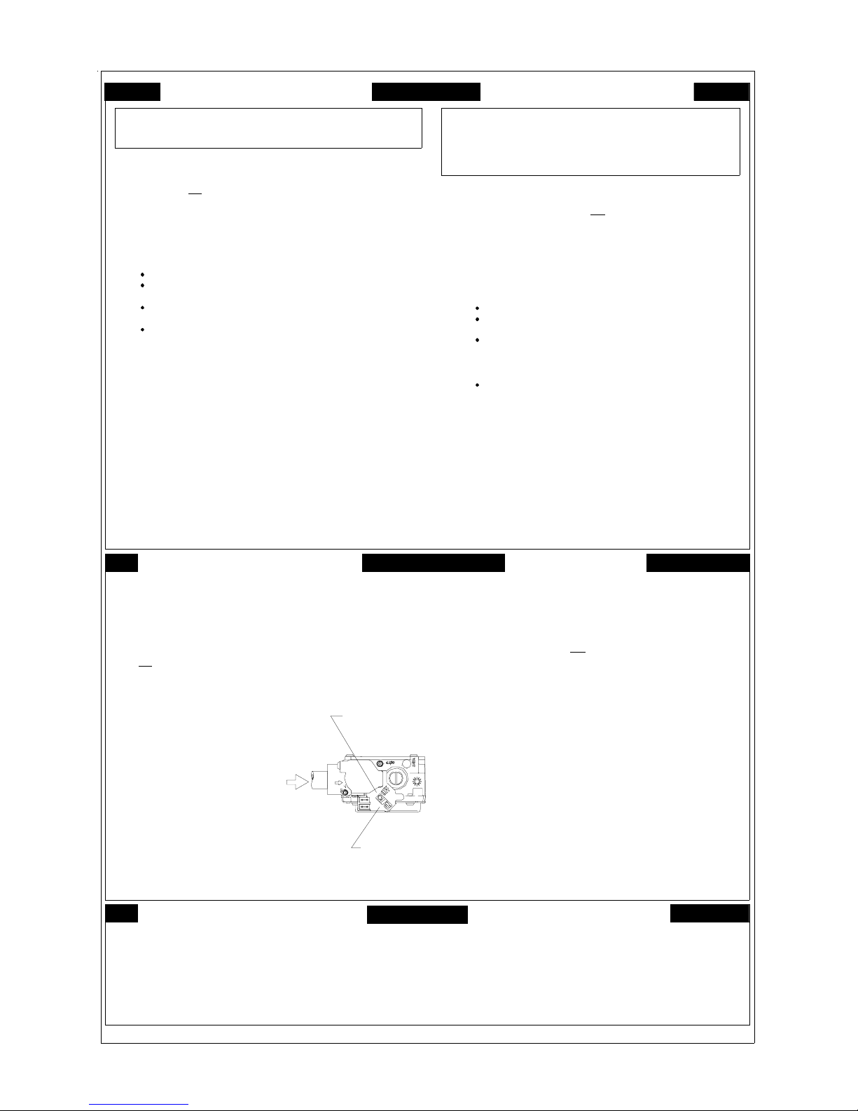
OPERATING INSTRUCTIONS
F
O
Y
O
R
U
R
E
A
D
B
E
F
y
f
I
o
n
d
u
ju
n
itio
O
s
t u
d
e
n
c
o
:
lt c
u
r
s
e
a
y
y
r
e
c
n
D
o
P
. B
m
e
flo
e
D
tr
t
o
t
t
s
t
a
i
. F
n
a
c
fir
h
u
r
o
y
r
t
F
o
.
s
i
h
t
c
a
a
e
n
a
a
u
o
f
lo
s
s
r
o
h
a
t
n
o
s
e
d
o
d
ic
v
e
w
e
h
ic
o
li
g
t
y
r
t
o
n
t
E
N
R
G
A
T
I
s
t
o
e
e
s
m
u
r
h
s
i
s
a
g
a
v
e
o
.
r
O
Y
O
S
F
U
I
to
y
lig
t
a
h
y
n
le
e
c
n
y
a
h
u
c
e
a
p
n
y
o
e
h
e
o
ls
r
n
l
a
ll
o
r
c
u
y
y
llo
a
g
w
e
t
h
e
r
t
o
n
e
t
c
y
y
h
a
c
d
tm
e
r
p
e
a
d
a
n
to
h
s
u
p
.
If th
le
e
e
v
t
i
e
a
ir
p
r
o
,
o
e
te
a
m
r
t
a
p
p
lia
i
e
c
n
ll
ie
if
d
l
a
q
u
a
to
r
e
d
p
n
la
c
g
o
r
o
t
n
c
s
a
A
R
W
N
IN
G
e
x
p
lo
io
s
m
n
a
o
n
s
r
p
e
l in
T
A
.
w
th
B
B
.
a
b
s
W
C
. U
N
h
te
o
D
D
.
Im
t
s
a
p
s
i
h
p
lia
a
h
it
ig
n
n
.
b
n
r
e
e
r
u
E
F
O
R
E
g
r
e
f
o
a
a
r
o
s
e
a
s
u
e
c
ttle
e
o
t
h
n
T
H
O
A
T
o
n
D
o
D
o
n
o
o
d
n
o
m
e
m
I
h
n
p
o
e
o
u
y
f
I
ll th
a
c
o
e
s
n
ly
y
o
to
e
s
u
r
e
v
e
't
o
n
d
d
a
n
,
h
n
c
ic
ia
.
n
l
p
x
e
r
o
i
o
s
e
u
s
o
t
n
o
e
ly
t
a
m
e
i
d
a
h
e
lia
p
p
n
a
d
n
m
e
t
s
y
S
R
A
F
E
T
Y
O
R
E
O
P
E
R
A
T
IN
G
llo
o
f
w
h
e
t
t
o
in
s
p
g
life
.
e
v
a
h
a
u
e
h
t
t
h
m
s
e
e
ll n
h
t
ie
r
M
E
a
lia
p
p
s
ic
r
t
o
y
in
s
g
s
a
s
s
p
u
g
a
r
o
u
n
t.
in
o
w
r
ill
a
l
l
a
c
t
p
r
e
d
y
a
n
f
v
e
r
s
a
e
n
l w
h
ic
e
s
ro
ty
e
r
p
e
is
t
I
.
lo
t
i
p
a
tic
to
m
a
y
ll
y
b
e
r
n
u
r
b
n
u
o
a
r
l
l
a
ll
e
x
flo
t
to
e
t
h
n
d
a
ir
a
n
a
G
A
S
L
L
e
.
n
c
w
h
;
c
t
i
b
r
ild
u
u
in
g
p
u
p
li
e
r
o
r
f
l
p
ie
's
in
r
tr
s
p
p
li
u
s
s
r
e
th
e
g
n
t
r
u
r
p
h
in
t
u
s
o
n
u
q
s
ie
d
f
li
a
y
a
m
a
ir
p
e
a
h
s
t
a
r
p
b
e
c
i
n
h
ic
c
e
t
p
y
t o
a
r
th
f
e
b
h
s
a
h
e
io
n
in
m
d
a
q
ip
u
lig
a
h
h
t
d
r
o
w
il
.
a
m
t
u
c
,
c
a
s
o
r
v
r
e
r
e
s
e
e
n
ia
n
c
e
u
n
s
t
tr
u
c
s
e
a
g
,
e
d
p
h
s
t
d
n
.
a
p
li
a
p
e
e
n
c
l
n
's
e
ig
o
r
b
h
io
.
n
s
n
l
o
tr
o
.
le
e
r
v
t
y
b
n
r
u
ic
e
u
lt in
a
fir
e
.
r
e
w
t
a
d
r
u
n
e
in
to
t
p
c
e
s
o
n
l
tr
o
.
r
e
w
a
t
d
r
e
n
A
R
V
A
E
I
L
A
V
E
R
S
S
E
T
M
I
la
le
ttr
le
e
is
e
d
q
u
r
e
tra
e
n
în
a
e
lle
o
r
p
r
o
c
C
e
p
a
p
t
A
.
m
n
u
i d
'u
o
t
a
u
m
a
d
'a
llu
m
A
B
.
V
A
N
le
if
e
n
r
r
u
e
d
o
e
n
c
ta
r
e
in
s
n
e
v
p
u
e
Q
U
E
N
N
n
A
e
R
f
S
C
D
in
N
e
o
u
p
.
q
la
'à
u
S
i la
m
a
r
e
r
a
é
p
r
te
te
n
d
e
le
c
d
é
n
c
s
a
p
N
e
.
d
l'e
s
n
a
te
h
ic
n
c
e
m
r
p
la
c
to
te
u
c
o
E
in
s
tr
c
u
s
le
c
h
e
d
é
c
t d
n
e
d
s
m
a
p
la
o
s
u
o
c
e
n
e
il
r
a
is
d
o
p
n
itif
s
n
e
t
iq
m
e
u
t
le
r
e
b
le
û
u
r
T
D
E
L
E
o
u
a
t
u
u
t
o
t
t
F
o
s
m
;
h
s
ie
r
d
r
u
. R
z
a
g
e
g
p
s
z
a
t
n
o
'a
u
s
m
c
c
u
R
E
A
I
S
e
t
n
t
s
a
p
e
h
r
e
u
o
c
t
e
a
u
is
il
r
e
'u
t
im
le
p
e
p
r
m
e
n
a
y
o
l
p
m
te
à
e
c
p
s
e
r
u
e
s
s
i
n
r
u
r
n
e
o
n
s
r
e
p
i
d
e
n
ie
c
.
s
u
o
t
u
o
e
r
s
n
a
in
;
e
j
a
e
tte
n
te
s
r
e
u
le
a
p
p
e
r
fo
la
e
r
c
m
r
x
e
u
e
n
r
e
ir
v
s
e
r
e
d
u
, c
a
lè
p
m
o
a
u
lifié
q
n
p
r
a
u
t
o
t
e
r
m
d
q
a
e
m
n
N
T
E
T
T
R
M
D
E
E
N
A
M
R
C
H
E
L
Q
u
i
e
n
q
u
o
n
N
tio
e
m
e
l
r
le
'IL
e
a
c
n
d
n
r
m
n
p
e
p
t
u
c
T
:
s
n
s
a
n
d
n
e
c
in
n
u
r
m
s
g
e
a
m
ie
v
e
d
e
t
r
e
t
p
r
o
a
p
s
'a
d
llu
g
a
m
le
û
r
u
b
r
N
.
m
e
u
lle
a
n
m
F
R
E
A
I
F
l'a
ie
d
e
p
r
a
p
r
p
le
e
if
n
r
lu
s
q
s
d
lo
u
r
iv
n
a
e
u
a
r
A
U
Y
'a
d
r
llu
m
e
r
e
in
t
n
u
c
u
n
u
h
p
o
é
l
é
t
d
é
ia
n
e
te
m
é
lé
p
h
t
le
t
la
le
tr
e
t
le
.
a
z
g
e
n
p
o
é
r
e
d
l
le
e
n
r
e
i
e
v
lo
p
m
e
a
is
o
in
c
e
,
é
c
n
e
c
t
h
ic
n
ie
n
e
n
tte
a
o
u
d
o
l
o
u
io
s
n
a
p
p
r
a
e
t
c
te
m
e
n
t o
u
in
r
o
u
c
e
p
s
è
t
s
y
s
d
u
e
i
n
o
i
p
é
é
t
t
e
le
e
s
p
é
r
u
o
u
ie
d
té
ie
a
r
ls
, d
u
m
h
a
in
s
e
ill
u
v
e
e
d
q
e
i a
u
llu
m
e
e
n
t
a
s
p
.
t
n
e
O
N
C
T
é
d
u
p
o
r
l
d
è
s
u
p
la
n
l'a
u
e
ir
e
t
l
.
o
s
d
u
u
O
N
D
E
l'a
ie
r
l
p
a
p
r
é
le
u
r
e
p
u
t
r
e
l
s
n
d
a
n
e
t le
fo
is
n
r
u
e
o
n
v
n
ú
d
tio
c
u
in
s
r
t
s
le
p
le
a
p
e
r
,
is
d
'a
s
m
d
r
d
r
e
'o
u
til à
te
e
p
n
s
a
q
u
a
lif
ié
.
e
l
a
r
p
a
e
in
d
e
n
c
n
u
'il
é
s
t
l
a
i
e
A
ie
.
t
r
a
p
n
e
te
l'a
r
a
p
p
m
c
e
d
e
n
o
lo
d
n
é
s
g
a
E
IR
E
te
e
c
p
s
e
r
n
t m
a
n
p
e
x
n
e
lé
s
e
s
e
.
e
l
I
.
e
s
e
e
r
t
IO
N
N
c
e
le
r
h
e
c
c
,
r
E
U
R
D
c
iq
e
u
r
t
m
e
i
b
t
â
d
u
r
e
s
is
o
in
.
d
s
n
u
s
ic
v
r
e
u
d
n
o
i
c
e
f
e
t
la
e
d
te
r
Q
u
ic
n
o
p
e
e
r
u
r
ie
.
p
lo
g
n
é
p
le
p
e
e
r
il e
t
e
le
ô
r
t
l'e
a
u
n
s
á
a
s
p
u
e
l
lo
io
s
n
io
s
s
n
t
s
E
R
,
a
r
E
G
A
Z
;
.
t
n
e
g
a
z
d
e
s
e
a
g
z
.
t
e
f
e
u
q
t
é
r
u
n
t
.
M
E
N
S
E
I
r
m
s
o
i
d
R
h
'y
s
o
i
e
e
p
le
p
s
itio
p
M
E
T
Ê
tio
s
n
le
r
th
l
e
r
'a
e
p
a
r
p
e
g
a
le
e
r
b
l
e
e
.
n
c
e
r
n
e
if
,
p
r
e
E
T
E
p
tio
r
o
a
p
a
e
le
.
n
ttr
e
e
l'a
p
t
le
r
e
a
p
r
io
n
t
c
d
z
e
l'
o
é
u
P
O
le
r
l'a
r
e
r
o
c
s
le
e
n
.
f
a
s
e
r
e
tt
R
lim
in
l
p
h
s
le
D
o
le
L
is
z
e
!
d
ie
e
u
r
r
u
é
p
o
m
r
e
t
a
t
s
n
ta
io
e
n
t
a
e
g
n
é
m
il
a
t
u
o
m
a
tiq
a
m
û
le
r
r
u
o
c
d
u
r
e
le
i
v
(
q
m
in
u
)
5
a
t
u
o
t
r
e
R
le
il
U
é
o
u
t
d
u
o
r
c
é
e
le
e
P
s
a
s
!
r
u
p
s
n
ie
r
é
d
s
d
'o
e
r
u
d
o
c
d
u
r
e
i
v
n
la
p
e
le
c
p
e
il
s
o
u
s
r
a
t
s
o
m
r
e
à
t
a
n
s
e
e
m
e
u
lé
it
in
.
s
e
t
il e
e
e
p
r
a
p
n
is
s
r
r
u
f
o
C
R
O
U
E
G
A
Z
m
e
r
h
t
t
s
o
lim
ta
e
n
tio
à
r
d
d
e
e
le
d
ie
v
r
u
.
e
r
c
r
la
p
e
c
e
n
A
R
C
H
E
o
i
t
c
u
r
in
t
s
s
c
e
t
e
e
t
e
m
t
la
à
é
le
tr
c
iq
d
t
n
a
t
é
r
pas
n
e
,
e
u
n
e
u
ll
e
m
d
e
l
ô
r
n
t
te
p
s
u
o
u
r
l'a
e
d
u
n
o
r
e
d
à
l'é
p
a
t
d
e
u
c
r
e
g
e
, p
z
a
d
e
l
ô
r
n
t
a
a
n
e
n
n
o
i
n
e
s
t
e
m
t
a
l
p
e
t
a
s
n
C
o
m
m
t a
e
p
le
p
d
e
r
u
e
P
E
R
D
E
L
la
à
t
a
n
é
le
c
o
s
é
ra
p
ô
r
n
t
o
c
le
p
a
n
s
d
e
s
n
é
tiq
e
tte
u
.
l
e
r
u
a
t
r
p
é
a
e
u
d
e
l'a
p
p
y
s
d
'u
n
é
o
t
e
y
a
s
e
s
t.
e
n
u
à
z
g
a
O
"
la
r
is
e
r
s
e
c
y
l,
i
e
a
r
p
p
d
e
r
g
u
e
a
s
n
i
e
d
s
B
e
tt
é
e
e
tiq
e
u
s
s
a
à
r
e
l'é
u
à
z
g
a
O
"
u
d
'a
c
c
.
s
é
.
e
d
e
r
u
a
t
p
r
é
c
r
m
a
e
h
, s
n
e
t c
p
u
le
o
t
n
u
r
n
h
c
e
.
g
z
a
'
L
A
D
M
'A
P
P
A
R
a
tu
m
e
r
p
é
t
tr
iq
e
d
u
e
t
io
d
s
n
'e
n
a
z
g
u
d
le
'a
d
c
a
u
n
e
r
c
z
ic
é
a
s
t
tte
u
r
I
l'a
c
r
u
s
é
it
r
u
c
e
s
a
b
s
lu
p
s
il.
e
r
è
t
e
m
à
F
F
/
A
R
R
E
T
"
to
e
p
r
a
p
h
o
.
S
u
r
ta
N
s
iy
l'a
i
S
E
r
tr
à
è
t le
u
is
r
p
m
c
i
c
io
t
.
e
p
/
M
e
é
r
i
e
r
d
n
e
S
u
d
s
è
p
r
'e
t
le
s
c
,
s
a
ié
it
r
u
c
é
s
d
s
n
e
.
é
u
iv
s
t
n
a
A
R
C
H
E
"
.
le
s
m
io
s
s
n
i
O
N
I
IL
e
.
s
s
b
a
lu
p
la
s
e
p
a
p
e
il
'il
r
s
tie
e
n
.
A
/
O
F
"
F
s
R
R
E
T
"
.
1
2
7
1
2
7
1
0
O
P
E
N
R
A
T
I
N
S
T
R
I
G
1
.
th
2
.
3
.
4
. T
D
5
. P
D
6
.
o
7
.
to
8
. R
9
.
1
0
1
1
s
1
.
2
.
3
. P
D
4
.
W
th
.S
.If
R
e
S
T
O
P
!
d
a
is
la
t
S
e
t
T
u
n
r
h
is
c
i
e
v
d
o
n
h
u
s
n
o
a
it f
m
s
e
ll
n
e
h
e
t
in
n
th
,
a
s
g
P
u
s
h
"
O
p
e
la
n
T
u
r
o
w
p
e
e
t th
th
e
o
f
llo
w
G
f
O
f
ic
v
r
e
T
t
S
e
t
n
T
u
r
s
if
e
h
u
s
o
n
R
e
p
t
l.
e
b
h
e
o
m
h
r
e
t
a
ll
o
w
p
f
o
f
a
lia
p
p
e
n
c
a
h
c
w
i
h
e
lig
o
t
y
r
t
o
t
th
c
e
g
a
s
e
.
c
o
r
f
o
t
in
m
iv
(
5
e
)
n
i
,
s
g
a
r
o
f
ll g
e
m
s
,
s
a
e
t
f
a
s
in
.
y
is
la
l if
e
b
y
t
x
e
n
o
t
o
g
r
n
o
t
c
a
s
g
.
N
"
e
a
c
e
s
c
c
a
ll
le
e
o
n
c
o
t
r
a
p
h
e
t
ta
s
o
t
m
r
e
a
lia
p
p
n
c
e
u
r
in
t
s
h
e
t
a
s
T
A
o
p
p
e
te
h
ic
n
c
O
T
U
R
m
e
r
h
t
h
e
o
ff a
ll e
le
is
o
t
ic
v
e
r
th
g
e
s
a
o
t fo
.
e
c
r
la
e
c
c
o
n
t
y
e
t
f
a
s
e
h
lo
w
o
t
t
a
t
s
e
r
a
th
o
e
t
is
e
ip
q
u
e
p
i
t
a
m
o
u
t
a
lly
c
n
b
r
u
h
e
t
h
t
n
o
tr
o
l le
e
v
u
te
to
s
c
le
c
e
n
d
u
in
g
l
S
F
T
O
P
!
io
n
t
a
m
r
o
f
d
o
u
o
s
't
n
.
e
p
t
s
le
e
r
v
l
o
p
s
e
a
n
l.
ic
r
t
p
lia
.
e
c
n
to
d
e
s
e
ir
d
w
ill n
o
t o
p
T
o
"
io
s
n
t
c
a
n
e
"
n
c
a
li
ia
o
n
g
r
a
s
N
O
F
F
o
o
lo
t
ta
s
t
tric
c
p
w
o
p
e
b
e
fo
r
c
tr
l
o
n
o
le
e
s
c
c
a
o
l
r
U
C
T
IO
N
S
1
.
A
R
R
o
i
t
a
m
r
o
in
f
s
t
e
s
in
g
t
e
t
ia
e
.
n
c
l
p
p
w
d
ith
a
n
ig
e
h
t
s
ig
h
t
l
e
h
n
a
b
y
r
to
r
O
F
"
F
o
a
r
u
t a
n
e
h
t
r
a
lo
o
f
B
"
"
o
llo
w
e
v
b
o
a
ll
e
m
G
IN
A
R
D
in
g
.
t
t
e
s
a
te
r
e
,
n
T
u
r
a
ll
u
r
o
c
y
d
o
m
c
p
.
y
n
a
G
T
A
S
e
s
w
t
e
s
to
r
e
th
e
m
d
.
r
e
to
e
r
v
O
"
e
l.
a
n
p
s
n
o
e
o
b
v
a
n
.
.
n
itio
n
.
e
n
r
u
b
r
.
d
P
o
"
io
.
n
t
i
s
g
y
. T
a
s
e
h
n
f
I
.
r
u
o
y
A
S
E
L
T
V
E
R
I
E
G
U
A
Z
O
A
P
in
tt
g
.
a
p
lia
p
P
F
F
"
R
O
B
M
A
N
U
O
N
"
L
IN
A
N
P
C
I
L
E
c
n
e
io
it
o
s
n
.
la
p
o
R
le
é
g
2
.
.
3
. C
p
o
u
a
C
e
t
4
.
d
'a
llu
a
llu
m
P
o
s
u
5
.
it
s
p
o
6
. A
te
t
n
g
.
z
a
p
la
n
8
1
1
7
.
. R
9
.
0
.
1
. S
d
q
1
2
fa
3
p
4
.
. C
.
.
c
A
R
R
la
r
u
s
S
'il n
P
o
s
u
p
it
s
o
e
m
r
t
t
e
M
R
l
é
g
e
i l'a
u
r
t
s
n
i
g
e
a
lifi
a
u
R
é
g
o
u
u
t p
P
o
u
o
s
N
e
R
e
m
G
A
A
N
Z
E
T
I
E
, E
L
N
P
O
M
/
M
E
V
O
S
A
R
C
H
E
"
A
N
G
U
A
A
S
L
E
R
S
H
N
O
W
N
P
O
S
IT
IO
N
20
Page 21
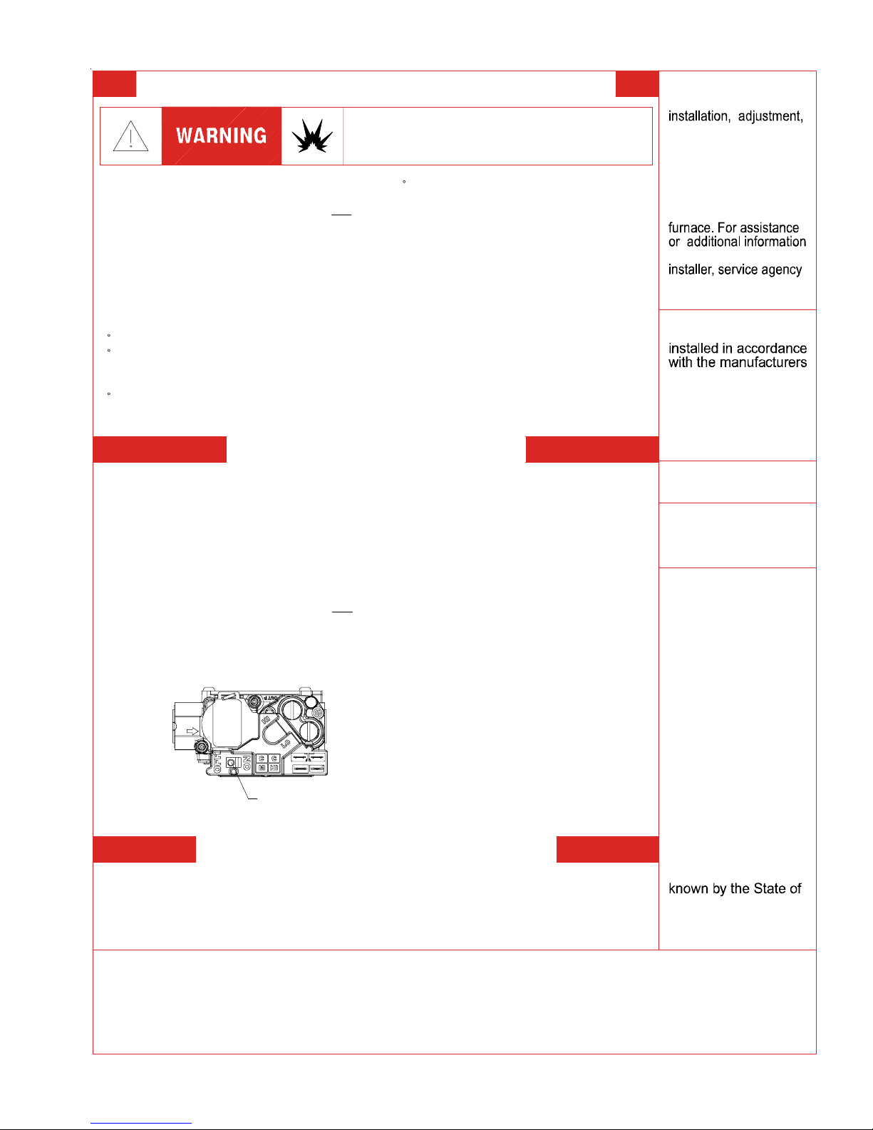
OPERATING INSTRUCTIONS
FOR YOUR SAFETY READ BEFORE OPERATING
If you do not follow these instructions exactly,
a fire or explosion may result causing property
damage, personal injury or loss of life.
A. This appliance does not have a pilot. It
is equipped with an ignition device which
automatically lights the burners. Do not
try to light the burners by hand.
B. BEFORE OPERATING smell around
the appliance area for gas. Be sure to
smell next to the floor because some gas
is heavier than air and will settle on the
floor.
WHAT TO DO IF YOU SMELL GAS
Do not try to light any appliance.
Do not touch any electric switch;
do not use any telephone in your
building.
Immediately call your supplier
from a neighbor's phone. Follow
the gas suppliers instructions.
If you cannot reach your gas supplier,
call the fire department.
C. Use only your hand to move the gas
control switch or knob. Never use
tools. If the gas control switch or knob
will not operate, don't try to repair it,
call a qualified service technician.
Force or attempted repair may result in
a fire or explosion.
D. Do not use this appliance if any part
has been under water. Immediately call
a qualified service technician to inspect
the appliance and to replace any part of
the control system and any gas control
which has been under water.
OPERATING INSTRUCTIONS
1. STOP! Read the safety information
2. Set the thermostat to lowest setting.
3. Turn off all electric power to the
appliance.
4. This appliance is equipped with an
automatic ignition system which
automatically lights the burners. Do not
try to light the burners by hand.
5. Remove control access panel.
6. Move the gas control switch or knob
to "OFF".
GAS CONTROL
SWITCH SHOWN
IN "ON" POSITION
7. Wait five (5) minutes to clear out any
gas. If you then smell gas, STOP!above on this label.
Follow "B" in the safety information
above on this label. If you don't smell
gas, go to the next step.
8. Move the gas control switch or knob
to "ON".
9. Replace control access panel.
10. Turn on all electric power to the
appliance.
11. Set the thermostat to the desired
setting.
12. If the appliance will not operate,
follow the instructions "To Turn Off Gas
To Appliance" and call your service
technician or gas supplier.
TO TURN OFF GAS TO APPLIANCE
1. Set the thermostat to its lowest setting.
2. Turn off all electric power to the
appliance if service is to be performed.
3. Remove control access panel.
4. Move the gas control switch or knob
to "OFF". Do not force.
5. Replace control access panel.
WARNING: Improper
alteration, service or
maintenance can
cause injury or
property damage.
Refer to the user's
information manual
provided with this
consult a qualified
or the gas supplier.
This furnace must be
instructions and local
codes. In the absence
of local codes, follow
the National Fuel Gas
Code, ANSI Z223.1.
For indoor installation.
PGB & PGJ
For outdoor
installation only.
If notWARNING:
installed, operated
and maintained in
accordance with the
manufacturer's
instructions, this
product could expose
you to substances
in fuel combustion
which can cause
death or serious
illness and which
are known to the
State of California to
cause cancer, birth
defects or other
reproductive harm.
This product contains
fiberglass insulation.
Fiberglass insulation
contains a chemical
California to cause
cancer.
FOR YOUR SAFETY
other flammable vapors and liquids in the vicinity of this
or any other appliance.
Do not store or use gasoline or
0140F00001P
21
Page 22
OPERATING INSTRUCTIONS
CONSIGNES DE SECURITE - LIRE
AVANT D'ALLUMER L'APPAREIL
AVERTISSEMENT: Le non-respect des instructions qui suivent peut
^
entrainer un risque d'incendie ou d'explosion causant des dommages,
des blessures ou la mort.
A. Cet appareil comporte pas de veilleuse. Il est muni d'un mecanisme qui allume
automatiquement le bruleur. N
B. Sentir tout autour de l'appariel AVANT D'ALLUMER afin de deceler toute fuite de gaz.
Assurez-vous de sentir tout pres du plancher car certains gaz sont plus lourds que l'air
et se deposeront sur le plancher.
SI VOUS SENTEZ UNE ODEUR DE GAZ:
Ne tentez d'allumer aucun appariel.
Ne touchez pas aux interrupteurs electriques; n'utiliser aucun telephone
dans l'edifice ou vous vous trouvez.
Appelez immediatement votre fournisseur de gaz en utilisant le telephone
d'un voisin et suivez les instructions du fournisseur.
Appelez les pompiers si vous ne parvenez pas a rejoindre votre fournisseur
de gaz.
C. N'utiliser que votre main pour pousser ou tourner le commande du gaz. N'utilisez
jamais d'outils. Si vous ne parvenez pas a pousser ou a tourner la commande, ne tentez
pas de la reparer; appelez un reparateur qualifie. Forcer la commande ou essayer de la
reparer peut entrainer un risque d'incendie ou d'explosion.
D. N'utilisez pas cet appareil si l'une de ses parties a ete dans l'eau. Si cela se produit,
demandez immediatement a un reparateur qualifie d'inspecter l'appareil et de remplacer
toute piece du systeme de controle et toute commande de gaz ayant ete dans l'eau.
^^
'allumez paz le bruleur manuellement.
^
^
0140F00002P
1. UN INSTANT! Lisez d'abord les consignes
INSTRUCTIONS DE SERVICE
de securite ci-dessus.
2. Reglez le thermostat a son point le plus bas.
3. Coupez l'alimentation electrique de l'appareil.
4. Cet appareil est muni d'un mecanisme qui
allume automatiquement le bruleur. Ne tentez
pas d'allumer le bruleur manuellement.
5. Retirez le panneau d'acces de la commande.
6. Mettez la commande de gaz a la position
^
ARRET ("OFF").
7. Attendez cinq (5) minutes afin de permettre a
tout gaz present d'etre evacue. Si vous sentez
une odeur de gaz a ce moment, ARRETEZ! et
suivez les consignes de securite donnees au
paragraphe B ci-dessus. Si vous ne sentez pas
de gaz, passez a l'etape suivante.
8. Mettez la commande de gaz a la position
MARCHE ("ON").
9. Remettez la panneau d'acces de la commande
en place.
10. Retablissez l'alimenation electrique de l'appareil.
11. Reglez le thermostat a le temperature desiree.
12. Si l'appareil ne fonctionne pas, suivez les
instructions intitulees "Arret du gaz" et appelez un
reparateur qualifie ou votre fournisseur de gaz.
1. Reglez le thermostat a son point le plus bas.
2. Coupez l'alimentation electrique de l'appareil si vous devez effectuer un entretien.
3. Retirez le panneau d'acces de la commande.
4. Mettez la commande de gaz a la position ARRET ("OFF").
5. Remettez le panneau d'acces de la commande en place.
^
^
^
^
^
^
ARRET DU GAZ
^
Commande de
gaz en position
"MARCHE"
22
Page 23
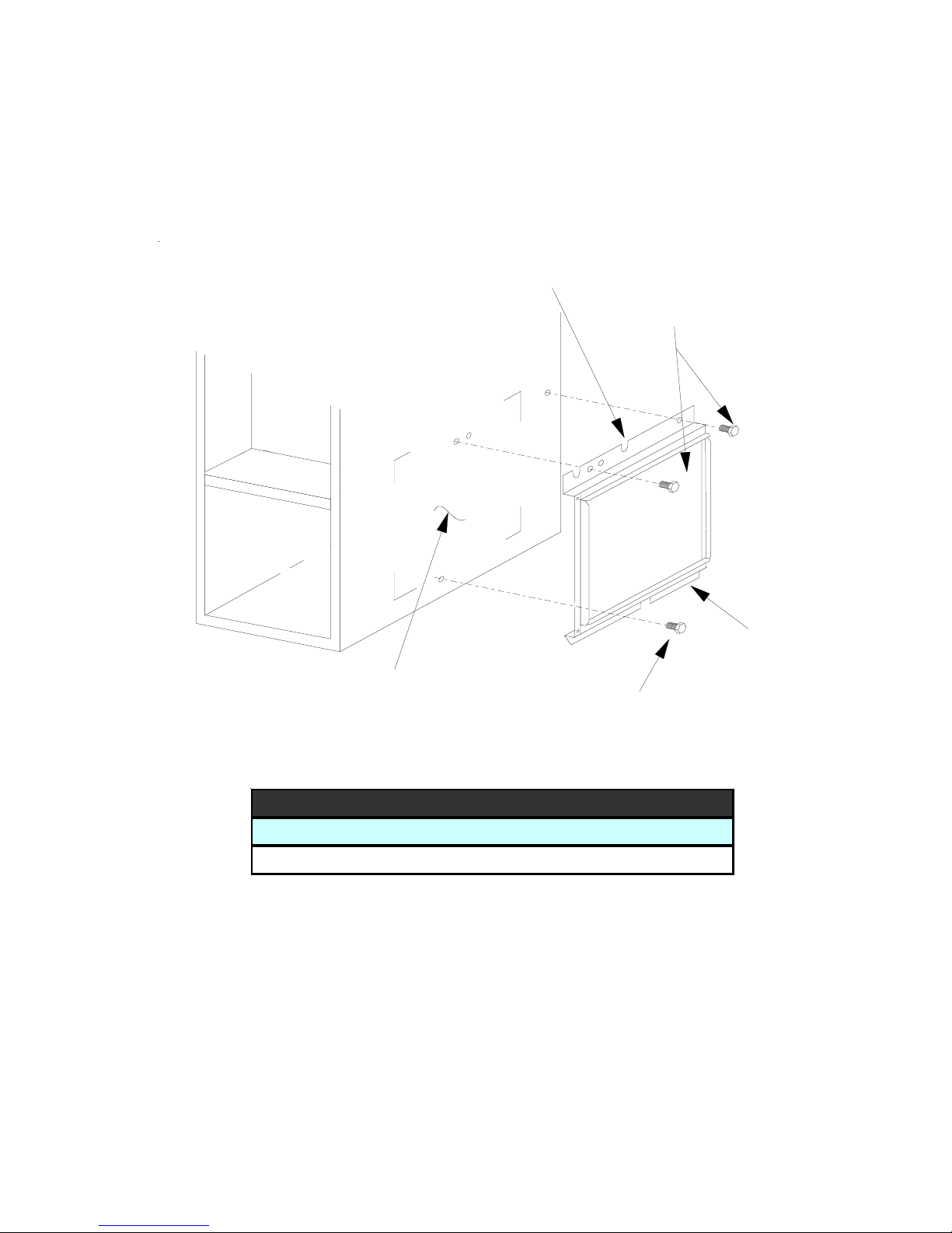
ACCESSORIES
EXTERNAL FILTER RACK KIT
( EFR01 )
SLOTS IN FILTER
CLEAR SCREWS
ON UNIT
UNIT SIDE
PANEL
BLOWER DECK
SCREWS
FRONT
OF UNIT
BASE
OF UNIT
RETURN AIR
CUTOUT AREA
LOWER EDGE
SCREW
EFR01 EXTERNAL FILTER RACK KIT
Used on Models
90% Upflow Model Furnaces
FILTER RACK ASSEMBLY
(FACE FILTER OPENING
TOWARDS FRONT
OF UNIT)
23
Page 24
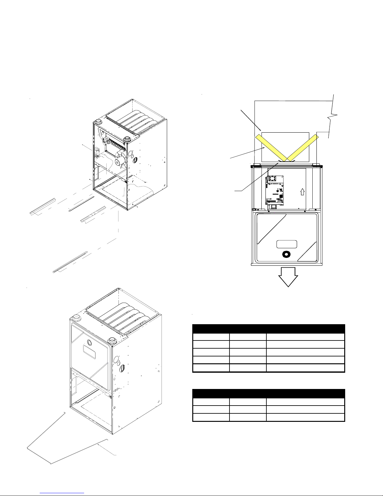
ACCESSORIES
INTERNAL FILTER RETENTION KIT
RF000180 RF000181
FILTER
ACCESS
DOOR
FILTER
ANGLE
SCREW
FILTER RAILS (2)
FILTER ANGLES (2)
FILTER
RAIL
SCREW
BASE
SIDE PANEL
FILTER
ANGLE
SCREW
FILTER
RAIL
SCREW
FI
LTER
RETURN
DUCT
FILTER
SUPPORT
BRACKET
AIR FLOW
F
LTER
I
RF000180
Quantity Part # Description
20 10690301 Filter Angle
20 20242801 Filter Rail
10 20178501 Filter Retainer
80 M0211216 Screw
1 20512701 Installation Instructions
INTO BACK PANEL LANCES,
FRONT TO BE PLACED
UNDER BASEPAN FLANGE.
24
INSERT LEGS
RF000181
Quantity Part # Description
10 10368501 Filter Bracket
20 M0211216 Screws
1 20512701 Installation Instructions
Each "RF" contains enough components to make
(10) filter kits.
Page 25
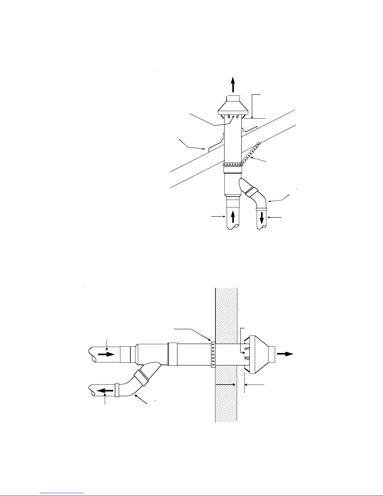
ACCESSORIES
CONCENTRIC VENT CONVERSION KIT
( DCVK-20
The DCVK-20 (2") or the DCVK30 (3") is a new concentric vent kit
approved with furnaces listed in
this manual.
This concentric vent kit allows for
vertical or horizontal vent termination. The illustrations give a brief
view of the kit and its application.
See the section in this manual
under "Vent Flue and Combustion
Air Pipe Terminations" for more
information or consult the Installation and Operating Instructions
(IO-619B).
DCVK-30 )
Combustion Air
Roof Boot/Flashing
(Field Supplied)
Vent
Vent
DCVK
Maintain 12" (18" for Canada)
minimum clearance above highest
anticipated snow level. Maximum of
24" above roof.
Support (Field Supplied)
45 Elbow
(Field Supplied)
Combustion Air
Vent
Combustion Air
Strap
(Field Supplied)
45 Elbow
(Field Supplied)
(Vertical Installation)
Combustion Air
Vent
Flush to
1" maximum
DCVK
(Horizontal Installation)
25
Page 26
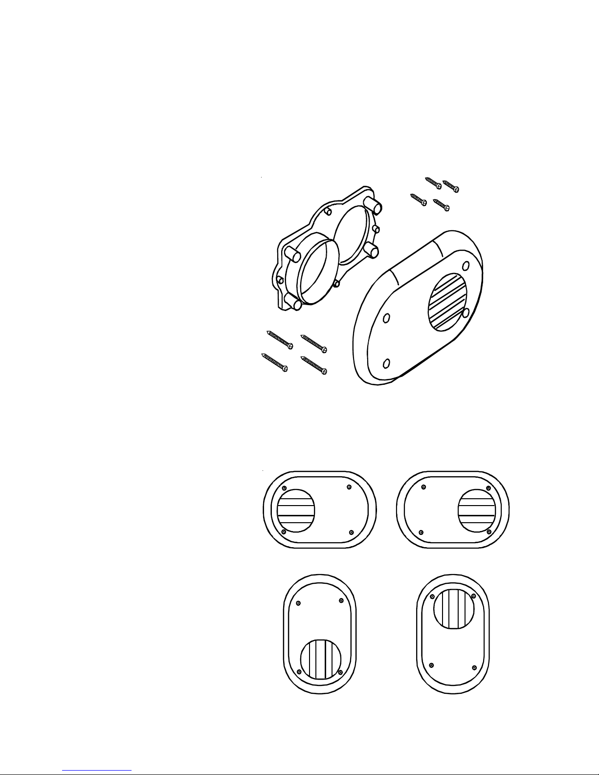
PRODUCT IDENTIFICATION
SIDE WALL VENT KIT
(0170K00000S)
Description
This side wall only vent kit #0170K00000S
is to be used with 2” or 3” vent systems.
This kit is NOT intended for use with
single pipe (indirect vent) installations.
The vent kit must terminate outside the
structure and may be installed with the
intake and exhaust pipes located sideby-side or with one pipe above the other.
See the section in this manual under "Vent
Flue and Combustion Air Pipe Terminations" for more information or consult the
Installation Instructions (IO-635).
26
Horizontal Installation
Vertical Installation
Page 27
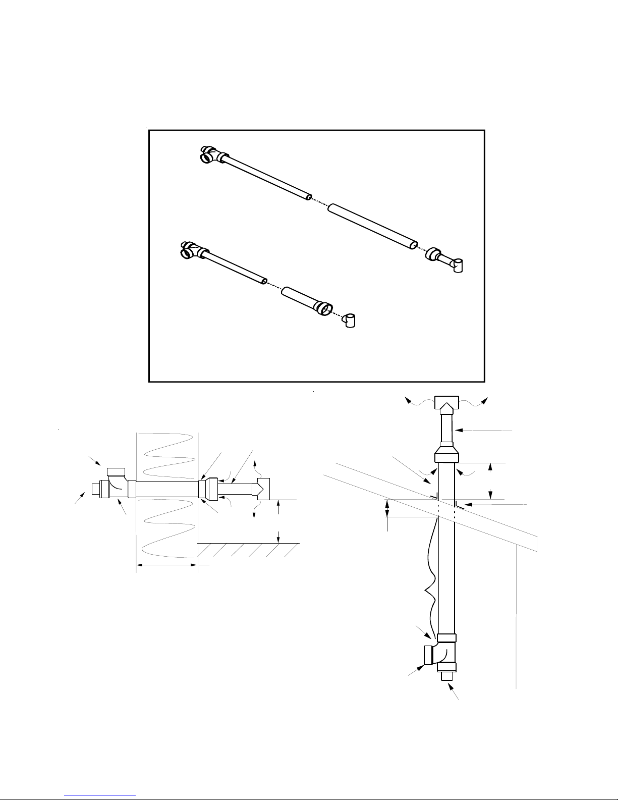
ACCESSORIES
CONCENTRIC VENT CONVERSION KIT
( HCVK
Horizontal
(HCVK)
VCVK )
Vertical
(VCVK)
Connection for
Fresh Air Intake
Pipe to Furnace
Connection for
Vent/Fl ue Pipe
from Furnace
Pipe to Furnace
Tee
Inside
Combustio n
Air Intake Pi pe
Outside
Seal Penetration
with Caulking
Wall Thickness
3/4" Minimum
13 3/4" Maximum
Vent/Flue Termination
with Tee
12" Minimum Above
Grade or Highest
Anticipated Snow Level
HVCK Installation
Concentric Vents Kits HVCK and VCVK are suitable for use
with the 90% efficient furnace products listed in this manual.
Combustion Air
Intake Pipe
Roof Thickness
3/4" Minimum
22" Maximum
Interior Section
of Concentric Vent Assembly
Must Be Adequately
Secured and Supported
Sanitary Tee
Connection for
Fresh Air Intake
Pipe to Furnace
(Tee, Pipe, & 2" to 4" Reducer)
12" Minimum Above
Roof or Highest
Anticipated Snow Level
Outside
Inside
Connection for
Vent/ Flue Pipe
From Furnace
Vent/Flue
Termination
Seal Penetration
with Flashing
and Caulking
VCVK Installation
27
Page 28

PRODUCT DESIGN
Safety
Please adhere to the following warnings and cautions when
installing, adjusting, altering, servicing, or operating the furnace.
WARNING
T
O PREVENT PERSONAL INJURY OR DEATH DUE TO IMPROPER INSTALLATION,
ADJUSTMENT, ALTERATI ON, SERVICE OR MAINTENANCE, R EFER TO THIS
MANUAL.
QUALIFIED INSTALLER, SERVICE AGENCY OR THE GAS SUPPLIER.
T
MAY CAUSE SERIOUS ILLNESS OR DEATH AND WHICH ARE KNOWN TO THE
S
REPRODUCTIVE HARM.
TO PREVENT POSSIBLE PROPERTY DAMAGE, PERSONAL INJURY OR DEATH
DUE TO ELECTRICAL SHOCK, THE FURNACE MUST BE LOCATED TO PROTECT
THE ELECTRICAL COMPONENTS FROM WATER.
Charge (ESD) Precautions
NOTE: Discharge body’s static electricity before touching
unit. An electrostatic discharge can adversely affect electrical components.
Use the following precautions during furnace installation and
servicing to protect the integrated control module from damage. By putting the furnace, the control, and the person at
the same electrostatic potential, these steps will help avoid
exposing the integrated control module to electrostatic discharge. This procedure is applicable to both installed and
uninstalled (ungrounded) furnaces.
1. Disconnect all power to the furnace. Do not touch the
2. Firmly touch a clean, unpainted, metal surface of the
3. Service integrated control module or connecting wiring
4. Discharge any static electricity from your body to ground
OR ADDITIONAL ASSISTANCE OR INFORMATION, CONSULT A
F
WARNING
HIS PRODUCT CONTAINS OR PRODUCES A CHEMICAL OR CHEMICALS WHICH
TATE OF CALIFORNIA TO CAUSE CANCER, BI RTH DEFECTS OR OTHER
WARNING
integrated control module or any wire connected to the
control prior to discharging your body’s electrostatic
charge to ground.
furnace near the control. Any tools held in a person’s
hand during grounding will be discharged.
following the discharge process in Step 2. Use caution
not to recharge your body with static electricity; (i.e., do
not move or shuffle your feet, do not touch ungrounded
objects, etc.). If you come in contact with an ungrounded
object, repeat Step 2 before touching control or wires.
before removing a new control from its container. Follow
Steps 1 through 3 if installing the control on a furnace.
Return any old or new controls to their containers before
touching any ungrounded object.
Product Application
This product is designed for use as a residential home gas
furnace. It is not designed or certified for use in mobile home,
trailer, or recreational vehicle applications.
This furnace can be used in the following non-industrial
commercial applications: Schools, Office buildings, Churches,
Retail stores, Nursing homes, Hotels/motels, Common or
office areas. In such applications, the furnace must be installed
with the
installation instructions.
The 80% and 90% furnaces are ETL certified appliances
and are appropriate for use with natural or propane gas.
(NOTE: If using propane gas, a propane conversion kit is
required).
One important difference between the 80% and 90% furance
is that the 90% furnace is a dual certified appliance.
Dual certification means that the combustion air inlet pipe is
optional and the furnace can be vented as a:
Non-direct vent (single pipe) central forced air furnace
in which combustion air is taken from the installation
area or from air ducted from the outside or,
Direct vent (dual pipe) central forced air furnace in which
all combustion air supplied directly to the furnace burners through a special air intake system outlined in
this manual and the installation instructions.
IMPORTANT NOTE: The 80% furnace cannot be installed
as a direct vent (i.e.., sealed combustion) furnace. The
burner box is present only to help reduce sound transmission from the burners to the occupied space.
To ensure proper installation, operation and servicing, thoroughly read the installation and service manuals for specifics pertaining to the installation, servicing and application of
this product.
WARNING
OSSIBLE PROPERTY DAMAGE, PERSONAL INJURY OR DEATH DUE TO FIRE,
P
EXPLOSION, SMOKE, SOOT, CONDENSTAION, ELECTRICAL SHOCK OR CARBON
MONOXIDE MAY RESULT FROM IMPROPER INSTALLATION, REPAIR, OPERATIO N,
OR MAINTENANCE OF THIS PRODUCT.
WARNING
T
O PREVENT PROPERTY DAMAGE, PERSONAL INJURY OR DEATH DUE TO FIRE,
DO NOT INSTALL THIS FURNACE IN A MOBILE HOME, TRAILER, OR RECREATIONAL
VEHICLE.
To ensure proper furnace operation, install, operate, maintain and service the furnace in accordance with the installation, operation and service instructions, all local building
codes and ordinances. In their absence, follow the latest
edition of the National Fuel Gas Code (NFPA 54/ANSI
Z223.1), and/or CAN/CGA B149 Installation Codes, local
plumbing or waste water codes, and other applicable codes.
A copy of the National Fuel Gas Code (NFPA 54/ANSI
Z223.1) can be obtained from any of the following:
28
Page 29
PRODUCT DESIGN
American National Standards Institute
1430 Broadway
New York, NY 10018
National Fire Protection Association
1 Batterymarch Park
Quincy, MA 02269
CSA International
8501 East Pleasant Valley
Cleveland, OH 44131
A copy of the CAN/CGA B149 Installation Codes can be
obtained from:
CSA International
178 Rexdale Boulevard
Etobicoke, Ontario, Canada M9W, 1R3
The rated heating capacity of the furnace should be greater
than or equal to the total heat loss of the area to be heated.
The total heat loss should be calculated by an approved
method or in accordance with “ASHRAE Guide” or “Manual
J-Load Calculations” published by the Air Conditioning Contractors of America.
Location Requirements and Considerations
WARNING
O PREVENT POSSIBLE EQUIPMENT DAMAGE, PROPERTY DAMAGE, PERSONAL
T
INJURY OR DEATH, THE FO LLOWING BULLET POINTS MUST BE OBSERVED
WHEN INSTALLING THE UNIT.
Follow the instructions listed below when selecting a furnace location. Refer also to the guidelines provided in the
Combustion and Ventilation Air Requirements section in this
manual or the installation instructions for details.
• Centrally locate the furnace with respect to the proposed or existing air distribution system.
• Ensure the temperature of the return air entering the
furnace is between 55°F and 100°F when the furnace
is heating.
• Provide provisions for venting combustion products
outdoors through a proper venting system. Special
consideration should be given to vent/flue pipe routing
and combustion air intake pipe when applicable.
80% Furnaces: All installations must be vented in
accordance with National Fuel Gas Code, NFPA 54/
ANSI Z223.1 - lateset edition. In Canada the furnaces
must be vented in accordance with the National Standard of Canada, CAN/CGA B149.
90% Furnaces: Refer to the Vent/Flue Pipe and Com-
bustion Air Pipe -Termination Locations section in this
manual or the installation instructions for appropriate
termination locations. Also for 90% furnaces, refer to
the Vent/Flue Pipe and Combustion Air Pipe -Termi-
nation Locations section in this manual or the installation instructions to determine if the piping system
from furnace to termination can be accomplished
within the guidelines given. NOTE: The length of flue
and/or combustion air piping can be a limiting factor
in the location of the furnace.
• Locate the 90% furnace so that the condensate can
be piped at a downward slope away from the furnace
to the drain. Do not locate the furnace or its condensate drainage system in any area subject to below
freezing temperatures without proper freeze protection. Refer to the Condensate Drain Lines and Trap
section in this manual or the installation instructions
for further details.
• Set the 90% furnace on a level floor to enable proper
condensate drainage. If the floor becomes wet or damp
at times, place the furnace above the floor on a concrete base sized approximately 1-1/2" larger than the
base of the furnace. Refer to the Horizontal Applica-
tions and Considerations section in this manual or
the installation instructions for leveling of horizontal
furnaces.
• Ensure upflow or horizontal furnaces are not installed
directly on carpeting, or any other combustible material. The only combustible material allowed is wood.
• A special accessory subbase must be used for upright counterflow unit installations over any combustible material (including wood). Refer to subbase instructions for installation details. (NOTE: A subbase
will not be required if an air conditioning coil is located
beneath the furnace between the supply air opening
and the combustible floor.
• Exposure to contaminated combustion air will result
in safety and performance-related problems. Do not
install the furnace where the combustion air is exposed to the following substances:
chlorinated waxes or cleaners
chlorine-based swimming pool chemicals
water softening chemicals
deicing salts or chemicals
carbon tetrachloride
halogen type refrigerants
cleaning solutions (such as perchloroethylene)
printing inks
paint removers
varnishes
hydrochloric acid
cements and glues
antistatic fabric softeners for clothes dryers
and masonry acid washing materials
• Seal off a non-direct vent furnace if it is installed near
an area frequently contaminated by any of the above
substances. This protects the non-direct vent furnace
from airborne contaminants. To ensure that the en-
29
Page 30
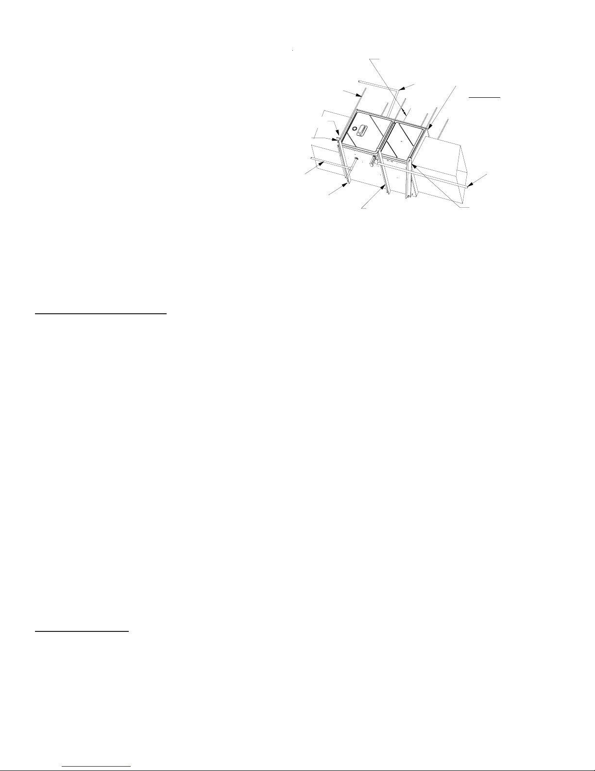
PRODUCT DESIGN
closed non-direct vent furnace has an adequate sup-
ply of combustion air, vent from a nearby uncontaminated room or from outdoors. Refer to the Combus-
tion and Ventilation Air Requirements section in this
manual or the installation instructions for details.
• If the furnace is used in connection with a cooling
unit, install the furnace upstream or in parallel with
the cooling unit coil. Premature heat exchanger failure will result if the cooling unit coil is placed ahead of
the furnace.
• If the furnace is installed in a residential garage, position the furnace so that the burners and ignition source
are located not less than 18 inches (457 mm) above
the floor. Protect the furnace from physical damage
by vehicles.
• If the furnace is installed horizontally, the furnace access doors must be vertical so that the burners fire
horizontally into the heat exchanger. Do not install
the unit with the access doors on the “up/top” or “down/
bottom” side of the furnace.
Clearances and Accessibility
Installations must adhere to the clearances to combustible
materials to which this furnace has been design certified.
The minimum clearance information for this furnace is provided on the unit’s clearance label. These clearances must
be permanently maintained. Refer to Specification Sheet for
minimum clearances to combustible materials. Clearances
must also accommodate an installation’s gas, electrical,
and drain trap and drain line connections. If the alternate
combustion air intake or vent/flue connections are used on
a 90% furnace, additional clearances must be provided to
accommodate these connections. Refer to Vent Flue Pipe
and Combustion Air Pipe section in this manual or the installation instructions for details. NOTE: In addition to the
required clearances to combustible materials, a minimum
of 24 inches service clearance must be available in front of
the unit.
A furnace installed in a confined space (i.e., a closet or
utility room) must have two ventilation openings with a total
minimum free area of 0.25 square inches per 1,000 BTU/hr
of furnace input rating. One of the ventilation openings must
be within 12 inches of the top; the other opening must be
within 12 inches of the bottom of the confined space. In a
typical construction, the clearance between the door and
door frame is usually adequate to satisfy this ventilation requirement.
Furnace Suspension
If suspending the furnace from rafters or joist, use 3/8"
threaded rod and 2”x2”x1/8” angle iron as shown in the following figure. If the furnace is installed in a crawl space it
must also be suspended from the floor joist or supported by
a concrete pad. Never install the furnace on the ground or
allow it to be exposed to water. The length of rod will depend
on the application and the clearances necessary.
PROVIDE 8" MINIMUM CLEARANCE BETWEEN
CENTER ROD AND FURNACE CABINET
TO ALLOW FOR CIRCULATOR BL OWER REMOVAL.
3/8" DIAMETER
THREADED ROD
(6 PLACES)
HOLD DOWN
NUTS
SUPPORT
NUTS
GAS PIPING
2"X2"X1/8" ANGLE IRON
(3 PLACES)
ALTERNATE
GAS PIPING
POSITION AS CLOSE AS POSSIBLE
TO BLOWER DECK TO ALLOW FOR
CIRCULATOR BLOWER REMOVAL.
ASSURE FURNACE IS LEVEL FROM
END TO END.
ON
90% FURNACES MAKE SURE
THE UNIT HAS A SLIGHT
FORWARD TILT WITH THE FRONT
OF THE FURNACE 0"-3/4"
BELOW THE BACK OF THE FURNACE.
CONDENSATE
DRAIN
TILT OUTWARD TO ALLOW FOR
DOOR AND CIRCULATOR BLOWER
REMOVAL.
90% Suspended Furnace Shown
(80% Furnace Similar)
EXISTING FURNACE REMOVAL
NOTE: When an existing furnace is removed from a venting
system serving other appliances, the venting system may
be too large to properly vent the remaining attached appliances.
The following vent testing procedure is reproduced from the
American National Standard/National Standard of Canada for
Gas-Fired Central Furnaces ANSI Z21.47, latest edition,
CSA-2.3b, latest edition Section 1.23.1.
The following steps shall be followed with each appliance connected to
the venting system placed in operation, while any other appliances
connected to the venting system are not in operation:
a. Seal any unused openings in the venting system;
b. Inspect the venting system for proper size and horizontal pitch,
as required by the National Fuel Gas Code, ANSI Z223.1 or the
CSA B149 Installation Codes and these instructions. Determine
that there is no blockage or restriction, leakage, corrosion and other
deficiencies which could cause an unsafe condition;
c. In so far as practical, close all building doors and windows and all
doors between the space in which the appliance(s) connected to
the venting system are located and other spaces of the building.
Turn on clothes dryers and any appliance not connected to the
venting system. Turn on any exhaust fans, such as range hoods
and bathroom exhausts, so they shall operate at maximum speed.
Do not operate a summer exhaust fan. Close fireplace dampers;
d. Follow the lighting instructions. Place the appliance being in-
spected in operation. Adjust thermostat so appliance shall operate continuously;
e. Test for draft hood equipped spillage at the draft hood relief
opening after 5 minutes of main burner operation. Use the flame
of a match or candle;
f. After it has been determined that each appliance connected to the
venting system properly vents when tested as outlined above,
return doors, windows, exhaust fans, fireplace dampers and any
other gas burning appliance to their previous conditions of use;
g. If improper venting is observed during any of the above tests, the
common venting system must be corrected.
30
Page 31

PRODUCT DESIGN
Corrections must be in accordance with the latest edition of
the National Fuel Gas Code NFPA 54/ANSI Z223.1 and/or
CSA B149 Installation Codes.
If resizing is required on any portion of the venting system,
use the appropriate table in Appendix G in the latest edition
of the National Fuel Gas Code ANSI Z223.1 and/or CSA B149
Installation Codes.
Thermostat Requirements
A single-stage furnace requires a single-stage thermostat
while the two-stage furnace requires a two-stage thermostat
for proper operation (see note below). The single-stage thermostat provides "W1" for only one stage of heat while the
two-stage thermostat provides "W1" and a "W2" terminals
for control of low stage and high stage heat. Refer to Electri-
cal Connections - 24 Volt Thermostat Wiring section in this
manual or the installation instructions for correct installation
procedure for these thermostats.
NOTE: A single-stage thermostat with only one heating
stage can be used to control a two-stage furnace. The application of a single-stage thermostat does not offer "true"
thermostat driven two-stage operation, but provides a timed
transition from low to high fire. The furnace will run on low
stage for a fixed period of time before stepping up to high
stage to satisfy the thermostat's call for heat. The delay
period prior to stepping up can be set at either 5 or 10 minutes through the DIP switch adjacent to the Heat Off delay
DIP switches on the integrated control module. To use a
single-stage thermostat, turn off power to the furnace, move
the thermostat selection jumper on the integrated contro
module from the "two-stage" position to the "single-stage"
position, turn power back on. Refer to the following figures.
T
W
TSTAT
O
S
I
N
G
L
E
T-Stat selection jumper in
single-stage thermostat
position.
ON
DIP switch position 3: ON
Delay Period: 10 minutes.
3
2
1
NOTE: The AMH, GCH, GDH, GMH and GME hybrid furnaces require a single stage thermostat. These furnaces
utilize a control board with single stage or two stage capability. The second stage feature is established by setting a
dip switch on the board, either one stage or two stage. All of
the second stage timing is then controlled by dipswitch 3 on
the circuit board.
T
W
O
TSTAT
S
I
OFF
N
G
L
E
DIP switch position 3: OFF
Delay Period: 5 minutes.
3
2
1
HEAT OFF
DELAY
MODE
SECOND
STAGE
ONLY
100
SECOND
DELAY
2-STAGE
5
MINUTES
1
F
F
O
2
F
F
O
3
F
F
O
N
O
N
O
N
O
150
SECOND
DELAY
1-STAGE
AUTO
Dehumidistat Requirements
A dehumidistat can be used in conjunction with the twostage variable speed 80% or 90% furnace to lower the humidity in the conditioned space. The dehumidistat will improve dehumidification of the conditioned air by prompting
the furnace to reduce the speed of the circulator blower during operation in the cooling mode. To be compatible with
these furnaces, a dehumidistat must operate on 24 VAC
and utilize a switch which opens on humidity rise. Refer
to Electrical Connections - 24 Volt Dehumidistat Wiring section in this manual or the installation instructions for correct
installation procedure.
Thermostat and Dehumidistat Location
In an area having good air circulation, locate the thermostat
and dehumidistat (if applicable) about five feet high on a vibration-free inside wall. Do not install the thermostat or
dehumidistat where it may be influenced by any of the following:
• Drafts, or dead spots behind doors, in corners, or under cabinets.
• Hot or cold air from registers.
• Radiant heat from the sun.
• Light fixtures or other appliances.
• Radiant heat from a fireplace.
• Concealed hot or cold water pipes, or chimneys.
• Unconditioned areas behind the thermostat and
dehumidistat, such as an outside wall.
DRAFTS OR DEAD SPOTS
-BEHIND DOORS
-IN CORNERS
-UNDER CABINETS
HOT
COLD
Thermostat Influences
31
Page 32

PRODUCT DESIGN
Consult the instructions packaged with the thermostat and
dehumidistat for mounting instructions and further precautions.
COMBUSTION AND VENTILATION AIR
REQUIREMENTS
WARNING
OSSIBLE PROPERTY DAMAGE, PERSONAL INJURY OR DEATH MA Y OCCUR
P
IF THE FURNACE IS NOT PROVIDED WITH ENOUGH FRESH AIR FOR PROPER
COMBUSTION AND VENTILAT ION OF FLUE GASES. MOS T HOMES REQUIRE
OUTSIDE AIR BE SUPPLIED TO THE FURNACE AREA.
9.3.1.5 Makeup air requirements for the operation of exhaust fans, kitchen
ventilation systems, clothes dryers, and fireplaces shall be considered in
determining the adequacy of a space to provide combustion air requirements.
9.3.2 Indoor Combustion Air. The required volume of indoor air shall
be determined in accordance with the method in 9.3.2.1 or 9.3.2.2 except that where the air infiltration rate is known to be less than 0.40
ACH, the method in 9.3.2.2 shall be used. The total required volume
shall be the sum of the required volume calculated for all appliances
located within the space. Rooms communicating directly with the space
in which the appliances are installed through openings not furnished
with doors, and through combustion air openings sized and located in
accordance with 9.3.2.3, are considered a part of the required volume.
Improved construction and additional insulation in buildings
have reduced heat loss by reducing air infiltration and escape around doors and windows. These changes have helped
in reducing heating/cooling costs but have created a problem supplying combustion and ventilation air for gas fired
and other fuel burning appliances. Appliances that pull air
out of the house (clothes dryers, exhaust fans, fireplaces,
etc.) increase the problem by starving appliances for air.
If this furnace is to be installed in the same space with other
gas appliances, such as a water heater, ensure there is an
adequate supply of combustion and ventilation air for the
other appliances. Refer to the latest edition of the National
Fuel Gas Code NFPA 54/ANSI Z223.1 (Section 9.3), or CAN/
CGA B149 Installation Codes (Sections 7.2, 7.3, or 7.4), or
applicable provisions of the local building codes for determining the combustion air requirements for the appliances.
Most homes will require outside air be supplied to the furnace area by means of ventilation grilles or ducts connecting directly to the outdoors or spaces open to the outdoors
such as attics or crawl spaces.
The following information on air for combustion and ventilation
is reproduced from the National Fuel Gas Code NFPA 54/ANSI
Z223.1 Section 9.3.
9.3* Air for Combustion and Ventilation.
9.3.2.1* Standard Method. The minimum required volume shall be 50
3
per 10000/Btu/hour (4.8m3/kW).
ft
9.3.2.2* Known Air Infiltration Rate Method. Where the air infiltration rate of a structure is known, the minimum required volume shall be
determined as follows:
(1) For appliances other than fan-assisted, calculate using the following
equation:
Required Volume
(2) For fan-assisted appliances, calculate using the following equation:
Required Volume
where:
I
I
ACH = air change per hour (percent of volume of space exchanged
(3) For purposes of this calculation, an infiltration rate greater than
= all appliances other than fan-assisted input in Btu per
other
fan
0.60 ACH shall not be used in the equations in 9.3.2.2(1) and
9.3.2.2(2).
hour
= fan-assisted appliances input in Btu per hour
per hour, expressed as a decimal)
> ________ _________
other
> ________ _________
fan
3
21 ft
ACH 1000 Btu/hr
15 ft
ACH 1000 Btu/hr
I
other
(
3
I
(
fan
)
)
9.3.1 General.
9.3.1.1 Air for combustion, ventilation, and dilution of flue gases for
appliances installed in buildings shall be obtained by application of one
of the methods covered in 9.3.2 through 9.3.6. Where the requirements
of 9.3.2 are not met, outdoor air shall be introduced in accordance with
methods covered in 9.3.3 through 9.3.6.
Exception No. 1: This provision shall not apply to direct vent appliances.
9.3.1.2 Appliances of other than natural draft design and other than
Category 1 vented appliances shall be provided with combustion, ventilation, and dilution air in accordance with the appliance manufacturer’s
instructions.
9.3.1.3 Appliances shall be located so as not to interfere with proper
circulation of combustion, ventilation, and dilution air.
9.3.1.4 Where used, a draft hood or a barometric draft regulator shall be
installed in the same room or enclosure as the appliance served so as to
prevent any difference in pressure between the hood or regulator and the
combustion air supply.
32
9.3.2.3 Indoor Opening Size and Location. Openings used to connect
indoor spaces shall be sized and located in accordance with the following:
(1)*Combining spaces on the same story. Each opening shall have a
minimum free area of 1 in.2/1000Btu/hr (2200 mm2/kW) of the total
input rating of all appliances in the space but not less than 100 in.
(0.60m2). One opening shall commence within 12 in. (300 mm) of
the top, and one opening shall commence within 12 in. (300 mm) of
the bottom, of the enclosure [see Figure A.9.3.2.3(1)]. The mini-
mum dimension of air openings shall be not less than 3 in. (80 mm).
2
Page 33

PRODUCT DESIGN
A
NOTE: Each opening must have
a free area of not less than one
square inch per 1000 BTU of
the total input rating of all equipment in the enclosure, but not
less than 100 square inches.
Chimney or G as Vent
Furnace
Water
Heater
Opening
Opening
Chimney or Gas Vent
Water
Heater
Furnace
Ventilation louvers
(each end of attic)
Outlet A ir
Inlet air duct
[ends 1 ft (300 mm)
above floor]
NOTE: The inlet and outlet air
openings must each have a free
area of not less than one square
inch per 4000 BTU of the
total input rating of all equipment
in the enclosure.
Figure A.9.2.3.3.(1) All Combustion Air from Adjacent
Indoor Spaces through Indoor Combustion Air Openings.
(2) Combining spaces in different stories. The volumes of spaces in
different stories shall be considered as communicating spaces where
such spaces are connected by one or more openings in doors or
floors having a total minimum free area of 2 in.2/1000 Btu/hr (4400
mm2/kW) of total input rating of all appliances.
9.3.3 Outdoor Combustion Air. Outdoor combustion air shall be
provided through opening(s) to the outdoors in accordance with the
methods in 9.3.3.1 or 9.3.3.2. The minimum dimension of air openings
shall not be less than 3 in. (80 mm).
9.3.3.1 Two Permanent Openings Method. Two permanent openings, one commencing within 12 in. (300 mm) of the top and one commencing within 12 in. (300 mm) of the bottom, of the enclosure shall be
provided. The openings shall communicate directly, or by ducts, with
the outdoors or spaces that freely communicate with the outdoors, as
follows:
(1)*Where directly communicating with the outdoors or where commu-
nicating to the outdoors through vertical ducts, each opening shall
have a minimum free area of 1 in.2/4000 Btu/hr (550 min2/kW) of
total input rating of all appliances in the enclosure. [See Figure
A.9.3.3.1(1)(a) and Figure A.9.3.3.1(1)(b).]
Chimney or Gas Vent
Ventilation louvers
(each end of attic)
NOTE: The inlet and outlet air
openings must each have a free
area of not less than one square
inch per 4000 BTU of the
total input rating of all equipment
in the enclosure.
Outlet Air
Water
Heater
lternate
air inlet
Furnace
Inlet Air
Figure A.9.3.3.1(1)(b) All Combustion Air
From Outdoors through Ventilated Attic.
(2)*Where communicating with the outdoors through horizontal ducts,
each opening shall have a minimum free area of 1 in.2/2000 Btu/hr
(1100 min2/kW) of total input rating of all appliances in the enclosure. [See Figure A.9.3.3.1(2).]
Chimney or Gas Vent
NOTE: The air duct openings
must have a free area of not
less than one square inch per
2000 BTU of the total input
rating of all equipment in the
enclosure*.
Furnace
Water
Heater
Outlet air duct
Inlet air duct
Figure A.9.3.3.1(2) All Combustion Air From Outdoors
through Horizontal Ducts.
9.3.3.2* One Permanent Opening Method. One permanent open-
ings, commencing within 12 in. (300 mm) of the top of the enclosure,
shall be provided. The appliance shall have clearances of at least 1 in. (25
mm) from the sides and back and 6 in. (150 mm) from the front of the
appliance. The opening shall directly communicate with the outdoors or
shall communicate through a vertical or horizontal duct to the outdoors
or spaces that freely communicate with the outdoors (see Figure
A.9.3.3.2) and shall have a minimum free area of the following:
(1) 1 in.
2
/3000 Btu/hr (700 mm2 per kW) of the total input rating of all
appliances located in the enclosure, and
(2) Not less than the sum of the areas of all vent connectors in the
space.
Ventilation louver s for
unheated crawl sp ace
Figure A.9.3.3.1(1)(a) All Combustion Air From Outdoors -
Inlet Air from Ventilated Crawl Space and Outlet Air
to Ventilated Attic.
33
Page 34

PRODUCT DESIGN
NOTE: The single opening mus t have
a free area of not less than one
square inch per 3000 BTU of
the total in put rating of all equi pment in the enclosure, but not less than
the sum of t he areas of all ven t
connectors in the confined space.
Chimney or Gas Vent
Furnace
Water
Heater
Opening
Alternat e
Opening
Locatio n
9.3.7 Louvers, Grilles, and Screens.
9.3.7.1 Louvers and Grilles. The required size of openings for com-
bustion, ventilation, and dilution air shall be based on the net free area of
each opening. Where the free area through a design of louver or grille or
screen is known, it shall be used in calculating the size opening required
to provide the free area specified. Where the louver and grille design and
free area are not known, it shall be assumed that wood louvers will have
25 percent free area, and metal louvers and grilles will have 75 percent
free area. Nonmotorized louvers and grilles shall be fixed in the open
position.
9.3.7.2 Minimum Scree Mesh Size. Screens shall not be smaller than
1/4 in. mesh.
Figure A.9.3.3.2 All Combustion Air
From Outdoors through Single Combustion Air Opening.
9.3.4 Combination Indoor and Outdoor Combustion Air. The use of
a combination of indoor and outdoor combustion air shall be in accordance with (1) through (3) (see example calculation in Annex J]:
(1) Indoor Openings: Where used, openings connecting the interior
spaces shall comply with 9.3.2.3.
(2) Outdoor Opening(s) Location. Outdoor opening(s) shall be located
in accordance with 9.3.3.
(3) Outdoor Opening(s) Size. The outdoor opening(s) size shall be
calculated in accordance with the following:
(a) The ratio of the interior spaces shall be the available volume of
all communicating spaces divided by the required volume.
(b) The outdoor size reduction factor shall be 1 minus the ratio of
interior spaces.
(c) The minimum size of outdoor opening(s) shall be the full size
of outdoor opening(s) calculated in accordance with 9.3.3,
multiplied by the reduction factor. The minimum dimension
of air openings shall not be less than 3 in. (80 mm).
9.3.5 Engineered Installations. Engineered combustion air installations shall provide an adequate supply of combustion, ventilation, and
dilution air and shall be approved by the authority having jurisdiction.
9.3.6 Mechanical Combustion Air Supply. Where all combustion air
is provided by a mechanical air supply system, the combustion air shall
be supplied form outdoors at the minimum rate of 0.35 ft3/min per 1000
Btu/hr (0.034 m3/min per kW) for all appliances located within the
space.
9.3.6.1 Where exhaust fans are installed, additional air shall be provided
to replace the exhausted air.
9.3.7.3 Motorized Louvers. Motorized louvers shall be interlocked
with the appliance so they are proven in the full open position prior to
main burner ignition and during main burner operation. Means shall be
provided to prevent the main burner form igniting should the louver fail
to open during burner startup and to shut down the main burner if the
louvers close during burner operation.
9.3.8 Combustion Air Ducts. Combustion air ducts shall comply with
9.3.8.1 through 9.3.8.8.
9.3.8.1 Ducts shall be constructed of galvanized steel or a material having equivalent corrosion resistance, strength, and rigidity.
Exception: Within dwellings units, unobstructed stud and joist spaces
shall not be prohibited from conveying combustion air, provided that not
more than one fireblock is removed.
9.3.8.2 Ducts shall terminate in an unobstructed space, allowing free
movement of combustion air to the appliances.
9.3.8.3 Ducts shall serve a single space.
9.3.8.4 Ducts shall not serve both upper and lower combustion air
openings where both such openings are used. The separation between
ducts servicing upper and lower combustion air openings shall be maintained to the source of combustion air.
9.3.8.5 Ducts shall not be screened where terminating in an attic space.
9.3.8.6 Horizontal upper combustion air ducts shall not slope down-
ward toward the source of combustion air.
9.3.8.7 The remaining space surrounding a chimney liner, gas vent, special gas vent, or plastic piping installed within a masonry, metal, or
factory built chimney shall not be used to supply combustion air.
9.3.6.2 Each of the appliances served shall be interlocked to the mechanical air supply system to prevent main burner operation where the
mechanical air supply system is not in operation.
9.3.6.3 Where combustion air is provided by the building’s mechanical
ventilation system, the system shall provide the specified combustion
air rate in addition to the required ventilation air.
34
Exception: Direct vent appliances designed for installation in a solid
fuel-burning fireplace where installed in accordance with the
manufacture’s installation instructions.
9.3.8.8 Combustion air intake openings located on the exterior of the
building shall have the lowest side of the combustion air intake openings
located at least 12 in. (300 mm) vertically from the adjoining grade level.
Page 35

PRODUCT DESIGN
Category I Venting (Vertical Venting)
(80% Furnaces Only)
WARNING
TO PREVENT POSSIBLE PERSONAL INJURY OR DEATH DUE TO
ASPHYXIATION, NON-CO NDENSING GAS FIRED WARM AIR FURNACES MUST
C
ATEGORY I VENTED. DO NOT VENT ANY OF THESE FURNACES USING
BE
CATEGORY III VE NTING.
Category I Venting is venting at a non-positive pressure. A
furnace vented as Category I is considered a fan-assisted
appliance and does not have to be "gas tight." NOTE: SingleStage and Two-Stage gas furnaces with induced draft blowers draw products of combustion through a heat exchanger
allowing in some instances common venting with natural
draft appliances (i.e. water heaters).
All installations must be vented in accordance with National
Fuel Gas Code NFPA 54/ANSI Z223.1 - latest edition. In
Canada, the furnaces must be vented in accordance with
the National Standard of Canada, CAN/CGA B149.1 and
CAN/CGA B149.2 - latest editions and amendments.
NOTE: The vertical height of the Category I venting system
must be at least as great as the horizontal length of the
venting system.
Upflow or Horizontal units are shipped with the induced
draft blower discharging from the top of the furnace ("Top" is
as viewed for an upflow installation). The induced draft blower
can be rotated 90 degrees for Category I venting. Refer to
the following figure. For horizontal installations, a four inch
single wall pipe can be used to extend the induced draft
blower outlet 1/2” beyond the furnace cabinet. Vent the furnace in accordance with the National Fuel Gas Code NFPA
54/ANSI Z223.1 - latest edition. In Canada, vent the furnace
in accordance with the National Standard of Canada, CAN/
CGA B149.1 and CAN/CGA B149.2 - latest editions and
amendments.
Supply
Air
WARNING
O PREVENT POSSIBLE DEATH OR PERSONAL INJURY DUE TO
T
ASPHYXIATION, COMMON VENTING WITH OTHER MANUFACTURER'S
INDUCED DRAFT APPLIANCES IS NOT ALLOWED.
The minimum vent diameter for the Category I venting system is as shown in the following chart:
MODEL
045
070
090
115
140
UPFLOW COUNTERFLOW
MINIMUM VENT
4 Inch 4 Inch
4 Inch 4 Inch
4 Inch 4 Inch
5 Inch 5 Inch
5 Inch 5 Inch
Under some conditions, larger vents than those shown above
may be required or allowed.
When an existing furnace is removed from a venting system
serving other appliances, the venting system may be too
large to properly vent the remaining attached appliances.
For complete details refer to Exisiting Furnace Removal section of this manual.
When resizing any portion of the common venting system,
use the appropriate table in Appendix G in the latest edition
of the National Fuel Gas Code NFPA 54/ANSI Z223.1.
80% Upflow Rotated Induced Draft Blower
WARNING
TO PREVENT DEATH OR SERIOUS IL LNESS TO BUILDING OCCUPANTS DUE
TO FLUE PRODUCTS LEAKING INTO THE BUILDING, PROPER INSTALLATION OF
GASKETS AND SCREWS IS ESSENTIAL FOR PROVIDING A GAS TIGHT SEAL
BETWEEN THE PARTITION PANEL AND THE INDUCED DRAFT BLOWER.
Make sure all wires are at least one inch from flue pipe.
Relocate junction box to right side of cabinet if necessary.
Refer to Electrical Connections section of this manual for
instructions.
35
Page 36

PRODUCT DESIGN
Masonry Chimneys
Proper Chimney
Termination?
(Check 1)
Yes
No
Line, terminate with
listed vent cap
(Fix 1)
Crown
Clay Tile Size Generally
12" x 12" (24" Length)
Breech
Clean Out
Throat
Damper
Wash
Clay Tile Size: 8" x 8" x12"
(Each x 24" Length)
Attic Floor
1/2" to 1" Air Space
Second Floor
First Floor
F.A.F. Vent
Connector
Fan Assisted
Forced Air
Furnace
Natural Draft
Water Heater
Roof Line
Water Heater
Vent Connector
Basement Floor
Chimney channel
free of solid and
liquid fuel
appliances?
(Check 2)
Yes
Crown in good
condition
(Check 3)
Yes
Cleanout free of
debris?
(Check 4)
Yes
Liner in good
condition?
(Check 5)
Yes
Dilution air
available?
(Check 6)
Yes
Complete the
installation.
(Check 7)
No
No
No
No
No
Change venting
arrangements
(Fix 2)
Rebuild crown
(Fix 3)
and/or Reline
(Fix 4)
Reline
(Fix 4)
Reline
(Fix 4)
Reline
(Fix 4)
Typical Multiple Flue Clay Tile Chimney
Checklist Summary
This checklist serves as a summary of the items to be
checked before venting an 80% furnace into a masonry
chimney. In addition, we recommend that a qualified serviceman use this checklist to perform a yearly inspection of
the furnace venting system.
This checklist is only a summary. For detailed information
on each of the procedures mentioned, see the paragraph
referenced with each item.
This inspection is based upon a draft topical report, "Masonry Chimney Inspection and Relining", issued by the Gas
Research Institute. While not yet finalized, we believe this
report represents the best information on this subject which
is currently available.
36
Check 1 - Proper chimney termination.
A masonry chimney used as a vent for gas fired equipment
must extend at least three feet above the highest point where
it passes through the roof. It must extend at least two feet
higher than any portion of a building within a horizontal distance of 10 feet. In addition, the chimney must terminate at
least 3 feet above any forced air inlet located within 10 feet.
The chimney must extend at least five feet above the highest connected equipment draft hood outlet or flue collar.
If the chimney does not meet these termination requirements,
but all other requirements in the checklist can be met, it
may be possible for a mason to extend the chimney. If this
will not be practical, see Fix 1.
Page 37

PRODUCT DESIGN
10' or Less
2' Min.
Ridge
Termination 10 Feet Or Less From Ridge, Wall or
Wall or
Parapet
Ridge
Termination More Than 10 Feet From Ridge, Wall or
Check 2 - Any solid or liquid fuel appliances vented
into this chimney channel.
Solid fuel appliances include fireplaces, wood stoves, coal
furnaces, and incinerators.
Liquid fuel appliances include oil furnaces, oil-fired boilers
and oil-fired water heaters.
Appliances which burn propane (sometimes referred to as
LP (liquefied petroleum)) gas are considered gas-fired appliances.
2' Min.
Wall or
Parapet
Chimney
10' or Less
2' Min.
Chimney
Parapet
More than 10'
: No Height
NOTE
above parapet
required when distance
from walls or parapet is
more than 10 feet.
More than 10'
10'
2' Min .
Chimney
Parapet
3' Min.
3' Min.
3' Min .
Chimney
Height above any
roof surface within
10 feet horizontally.
3' Min .
Check 3 - Chimney Crown Condition.
Damage from condensate usually shows up first in the crown.
If any of the following trouble signs are present, the condition of the crown is not satisfactory:
a) Crown leaning
b) Bricks missing
c) Mortar missing
d) Tile liner cracked
e) No tile liner
f) Salt staining at mortar joints. (White stains, and mor-
tar becomes sandy and/or erodes.)
For problems a, b, or c, see Fix 3. If problems d, e, or f are
present, see Fix 4. IMPORTANT: It may be necessary to
follow both Fix 3 and Fix 4.
Check 4 - Debris in Cleanout
A cleanout (dropleg) must be present such that the upper
edge of the cleanout cover is at least 12 inches below the
lower edge of the lowest chimney inlet opening.
A chimney without a cleanout could become partially blocked
by debris. If no cleanout is present, the chimney must be
relined (Fix 4).
Remove the cleanout cover, and examine the cleanout for
debris. If significant amounts of any of the following are found:
• Fuel oil residue
• Bricks
• Mortar or sand
• Pieces of the tile liner
• Rusted pieces of the metallic liner
reline the chimney (Fix 4).
Check 5 - Liner Condition.
If a metal liner is present, it must be checked. It cannot be
assumed that all existing metal liners are correctly installed
and in good condition.
Remove the lowest existing vent connector, and examine
the inside of the elbow or tee at the base of the liner. A small
amount of soot may be considered acceptable, provided the
installer vacuums it away. If rusted pieces of the liner have
collected here, the metal liner must be removed and replaced
(Fix 4).
Next, gently tap the inside of the liner with a Phillips screwdriver. If the screwdriver perforates the liner, or if the tapping
does not sound like metal hitting metal, the liner must be
removed and replaced (Fix 4).
Remember that all appliances must be vented inside the
liner. Venting one appliance inside the liner and another appliance outside the liner is not acceptable.
Next, use a flashlight and small mirror to sight up the liner.
B vent must be supported so as to not come into direct
contact with the chimney walls or tile liner. If it is not, it can
probably be rehung so as to be acceptable. A thimble or fire
stop may be helpful here.
37
Page 38

PRODUCT DESIGN
Flexible liners should be hung straight or nearly straight. If it
is spiraled in the chimney and in good condition, it should
be rehung. To do this, break the top seal; pull up and cut off
the excess liner length, and refit the top seal. Use caution
when doing this, as the cut edges of flexible liners may be
sharp.
The surfaces of the liner must be physically sound. If gaps
or holes are present, the metal liner must be removed and
replaced (Fix 4).
Finally, confirm that the metal liner is the correct size for the
appliances to be installed. Use the GAMA tables and rules.
If a metal liner is not present, a clay tile liner must be present,
or the chimney must be lined (Fix 4).
Use a flashlight and small mirror at the cleanout or vent
connector to inspect the clay tile liner. If any of the following
problems are present:
• Tile sections misaligned
• Tile sections missing
• Gaps between tile sections
• Signs of condensate drainage at the cleanout or vent
connectors
• Mortar protruding from between tile sections
• Use of sewer pipe or drainage pipe rather than an approved fire clay tile
reline the chimney (Fix 4).
Next, measure the size of the liner. It may be possible to do
this from the cleanout. The liner must be at least as large as
the minimum size established by the tables in National Fuel
Gas Code NFPA 54/ANSI Z223.1 - latest edition and in the
National Standard of Canada, CAN/CGA B149.1 and CAN/
CGA B149.2 - latest editions and amendments. If the liner
is too small or too large, then the chimney must be relined
(Fix 4).
Check 6 - Dilution Air.
If gas-fired appliances are to be vented into a clay tile liner,
a source of dilution air is required.
Dilution air cannot be obtained through:
• Induced draft appliances
• Natural draft appliances with vent dampers
Sufficient dilution air can ordinarily be obtained through the
draft hood of a natural draft appliance only if the appliance’s
vent connector does not include a vent damper.
If dilution air will not be available, the chimney must be relined (Fix 4).
Check 7 - Complete the Installation.
If Checks 1 through 6 have been satisfactory, and the liner
is an acceptable size as determined by the tables in National Fuel Gas Code NFPA 54/ANSI Z223.1 - latest edition
and in the National Standard of Canada, CAN/CGA B149.1
and CAN/CGA B149.2 - latest editions and amendments,
then the clay tile liner can probably be used as a vent for the
gas appliances. However, the installer must keep in mind
the following factors which may render the tile liner unsuitable for use as a vent:
38
• Extremely cold weather
• Long vent connectors
• Masonry chimneys with no air gap between the liner
and the bricks. (In practice, this can be difficult to
detect.)
• Exterior chimneys (The tables in National Fuel Gas
Code NFPA 54/ANSI Z223.1 - latest edition and in
the National Standard of Canada, CAN/CGA B149.1
and CAN/CGA B149.2 - latest editions and amendments assume interior chimneys.)
If, in the judgment of the local gas utility, installer, and/or
local codes; one or more of the above factors is likely to
present a problem, the chimney must be relined (Fix 4).
Fix 1 - Liner Termination.
Any cap or roof assembly used with a liner must be approved by the liner manufacturer for such use. The liner and
cap/roof assembly must then terminate above the roof in
accordance with the manufacturer’s instructions.
In some cases, a shorter extension above the roof may be
possible with a liner than would be required with a masonry
chimney.
For further information on relining, see Fix 4.
Fix 2 - Change Venting Arrangements
If the masonry chimney has more than one channel, it may
be possible to vent the gas appliances into one channel and
vent the solid or liquid fuel appliance(s) into another
channel(s). Do not vent an 80% furnace inside of a metal
liner with other appliances vented outside the liner.
Alternatively, the homeowner may agree to discontinue use
of the fireplace (solid fuel appliance). If so, the tile liner must
be cleaned to remove creosote buildup. The fireplace opening must then be permanently sealed.
If oil-fired appliance(s) are being replaced by gas-fired
appliance(s), the tile liner must first be cleaned to remove
the fuel oil residue.
If none of the above options are practical, the 80% furnace
may need to be vented vertically with B vent.
Under some conditions a 90%+ furnace could be installed
rather than an 80%. The 90% furnace can be vented horizontally or vertically through PVC pipe.
Fix 3 - Rebuild the Crown.
If the chimney crown is damaged, a qualified mason must
repair it in accordance with nationally recognized building
codes or standards. One such standard which may be referenced is the Standard for Chimneys, Fireplaces, Vents, and
Solid Fuel Burning Appliances, ANSI/NFPA 211.
Page 39

PRODUCT DESIGN
Fix 4 - Relining.
Relining options include B vent and flexible liners.
If the chimney has diagonal offsets, B vent probably cannot
be used.
If B vent is to be used, it must be supported adequately.
Supports (such as fire stops or thimbles) must be used to
prevent the B vent from coming into direct contact with the
tile liner or chimney walls. Direct contact would result in
higher heat loss, with an increased possibility of poor venting system performance.
It is not acceptable to vent one appliance inside the B vent
and other appliances outside. The excess space between
the B vent and the chimney walls must be covered at the top
of the chimney by a weatherproof, corrosion resistant flashing.
The B vent should then be topped with a listed vent cap. The
listed vent cap will, when installed per the manufacturer’s
instructions, prevent problems due to rain, birds, or wind
effects.
A B vent installed as described in this section is considered
to be an enclosed vent system, and the sizing tables in
National Fuel Gas Code NFPA 54/ANSI Z223.1 - latest edition and in the National Standard of Canada, CAN/CGA
B149.1 and CAN/CGA B149.2 - latest editions and amendments may be used.
If a flexible liner is to be used, it must be made of the proper
materials:
• For most residential applications, an aluminum liner
should be acceptable.
• If the combustion air supplied to the furnace will be
contaminated with compounds containing chlorine or
fluorine, a liner of AL29-4C stainless steel should be
used. Common sources of chlorine and fluorine compounds include indoor swimming pools and chlorine
bleaches, paint strippers, adhesives, paints, varnishes,
sealers, waxes (which are not yet dried) and solvents
used during construction and remodeling. Various commercial and industrial processes may also be sources
of chlorine/fluorine compounds.
• Heavier gauge 300 and 400 series stainless steel liners were developed for use with oil or solid fuel appliances. They are not suitable for use with gas-fired
appliances. Flexible liners specifically intended and
tested for gas applications are listed in the UL "Gas
and Oil Equipment Directory". (UL Standard 1777).
For sizing of flexible liners, see Note 22 and the tables in
the National Fuel Gas Code NFPA 54/ANSI Z223.1 - latest
edition and in the National Standard of Canada, CAN/CGA
B149.1 and CAN/CGA B149.2 - latest editions and amendments.
To install the liner, read and follow the liner manufacturer’s
instructions and your local codes. Excess liner length should
be pulled out of the chimney and cut off. Use caution when
doing this, as the cut edges of flexible liners may be sharp.
Do not spiral excess liner inside of the chimney. Support
the liner as recommended by the liner manufacturer.
Some manufacturers of flexible liners offer an insulation sleeve
designed to be added to the liner before it is installed in the
chimney. (Poured insulation, either vermiculite or other materials, is no longer recommended.) Insulation will need to
be added to the flexible liner if:
• It is required by the liner manufacturer’s instructions.
• The previous liner was properly sized and installed,
and suffered from condensation damage.
• It is required by your local building codes.
Even if none of those three conditions exist which require
additional liner insulation, the installer may wish to consider
it if:
• The local climate is very cold.
• The chimney is very tall.
• The vent connectors used are very long or have a large
number of elbows.
• Local experience indicates that flexible liners installed
without insulation are likely to have condensation problems.
Insulation must be selected and installed in accordance with
the liner manufacturer’s instructions.
Finally, cap the chimney and terminate the liner in accordance with the liner manufacturer’s instructions.
Horizontal Applications and Considerations
Horizontal applications, in particular, may dictate many of
the installation’s specifics such as airflow direction, ductwork connections, flue and/or combustion air pipe connections, etc. The basic application of this furnace as a horizontal furnace differs only slightly from an upright installation. When installing a furnace horizontally, additional consideration must be given to the following:
(90% Furnaces Only)
ALTERNATE VENT/F LUE
AND COMBUSTION AIR
INTAKE LOCATIONS
GAS LINE WITH
DRIP LEG (3" MINIMUM)
(90% Furnaces Only)
DRAIN PAN
FURNACE MUST BE SUPPORTED
AT BOTH ENDS AND MIDDLE
FURNACE M UST BE LEVEL
FROM END TO END
(90% Furnaces Only)
4 3/4" MINIMUM
DRAIN TRAP
CLEARANCE
36" MINIMUM SERVICE
CLEARANCE REQUIRED
(90% Furnaces Only)
FURNACE MUST BE LEVEL
OR SLIGHTLY TILTED FORWARD
WITH THE DOORS 0" - 3/4"
BELOW THE BACK PANEL
(90% Furnaces Only)
DRAIN LINE WITH 1/4" PER FOOT
DOWNWARD SLOPE
90% Horizontal Furnace Shown
(80% Horizontal Furnace Similar)
39
Page 40

PRODUCT DESIGN
Drain Trap and Lines (90% Furnaces Only)
In horizontal applications the condensate drain trap is secured to the furnace side panel, suspending it below the
furnace. A minimum clearance of 4 3/4" below the furnace
must be provided for the drain trap. Additionally, the appropriate downward piping slope must be maintained from the
drain trap to the drain location. Refer to Condensate Drain
Trap and Lines section in this manual or the installation
instructions for further details. If the drain trap and drain line
will be exposed to temperatures near or below freezing, adequate measures must be taken to prevent condensate from
freezing. NOTE: The use of insulation and/or heat tape is
recommended. Failure to provide proper condensate drainage can result in property damage.
Leveling (90% Furnaces Only)
Leveling ensures proper condensate drainage from the heat
exchanger and induced draft blower. For proper flue pipe
drainage, the furnace must be level lengthwise from end to
end. The furnace should also be level from back to front or
have a slight tilt with the access doors downhill (approximately 3/4") from the back panel. The slight tilt allows the
heat exchanger condensate, generated in the recuperator
coil, to flow forward to the recuperator coil front cover.
Alternate Vent/Flue and Combustion Air Connections
(90% Furnaces Only)
NOTE: Alternate combustion fresh air inlet location on the
right hand panel side of 90% furnace models has been
discontinued since November 2005.
In horizontal installations provisions for alternate flue and
combustion air piping are available for upflow furnaces with
left discharge. In these positions the flue and combustion
air piping can be run vertically through the side of the furnace. Refer to the following figure "Recommended Installation Positions" for further detail. The standard piping connections may also be used in these positions. Refer to Vent/
Flue Pipe and Combustion Air Pipe section in this manual
or the installation instructions for details concerning the conversion to the alternate vent/flue and combustion air connections on the 90% furnace.
AIR
DISCHARGE
Side
Return
Duct
Connection
AIR
DISCHARGE
UPFLOW HORIZONTAL
LEFT AIR DISCHARGE
Bottom
Return
Duct
Connection
UPFLOW HORIZONTAL
RIGHT AIR DISCHARGE
Bottom
Return
Duct
Connection
UPFLOW
UPRIGHT
ALTERNATE FLUE AND
COMBUSTION AIR PIPE
LOCATIONS
ALTERNATE FLUE AND
COMBUSTI ON AIR PIPE
LOCATIONS
Side
Return
Duct
Connection
Bottom
Return
Duct
Connection
AIR
DISCHARGE
Connection
COUNTERFLOW
UPRIGHT
Bottom
Return
Duct
Connection
COUNTERFLOW HORIZONTAL
RIGHT AIR DISCHARGE
AIR
DISCHARGE
COUNTERFLOW HORIZONTAL
LEFT AIR DISCHARGE
Bottom
Return
Duct
ALTERNATE FLUE AND
COMBUSTION AIR PIPE
LOCATIONS
AIR
DISCHARGE
ALTERNATE FLUE AND
COMBUSTION AIR PIPE
LOCATIONS
AIR
DISCHARGE
Bottom
Return
Duct
Connection
90% Furnace Recommended Installation Positions
NOTE: Alternate "vertical" piping connections can not be
used when an upflow 90% furnace is installed with supply
air discharging to the right or when a counterflow furnace is
installed with supply discharging to the left. In this case,
use the standard flue and combustion air piping connections
Alternate Electrical and Gas Line Connections
The 80% & 90% furnaces have provisions allowing for electrical and gas line connections through either side panel. In
horizontal applications the connections can be made either
through the “top” or “bottom” of the furnace.
Drain Pan (90% Furnaces Only)
A drain pan must be provided if the furnace is installed above
a conditioned area. The drain pan must cover the entire area
under the furnace (and air conditioning coil if applicable).
40
Freeze Protection (90% Furnaces Only)
If the drain trap and drain line will be exposed to temperatures near or below freezing, adequate measures must be
taken to prevent condensate from freezing. NOTE: The use
of insulation and/or heat tape is recommended. Failure to
provide proper condensate drainage can result in property
damage.
Page 41

PRODUCT DESIGN
Propane Gas and/or High Altitude Installations
WARNING
P
OSSIBLE PROPERTY DAMAGE, PERSONAL INJURY OR DEATH MAY OCCUR IF
THE CORRECT CONV ERSION KITS ARE NOT INSTALLED.
MUST BE APPLIE D TO INSURE SAFE AN D PROPER FURNACE OPERATI ON.
CONVERSIONS MUST BE PERFORMED BY A QUALIF IED INSTALLER OR SERVICE
AGENCY.
THE APPROPRIATE KITS
ALL
Do not use commercially available “no hub connectors” other
than those shipped with this product.
It is the responsibility of the installer to follow the manufac-
turers’ recommendations and to verify that all vent/flue piping and connectors are compatible with furnace flue products. Additionally, it is the responsibility of the installer to
ensure that all piping and connections possess adequate
structural integrity and support to prevent flue pipe separation, shifting, or sagging during furnace operation.
This furnace is shipped from the factory configured for natural gas at standard altitude. Propane gas installations require an orifice change to compensate for the energy content difference between natural and propane gas.
High altitude installations may require both a pressure switch
and an orifice change. These changes are necessary to compensate for the natural reduction in the density of both the
gas fuel and the combustion air at higher altitude.
Refer to the Accessories Charts in this manual or product
Specification Sheet for a tabular listing of appropriate
manufacturer’s kits for propane gas and/or high altitude installations. The indicated kits must be used to insure safe
and proper furnace operation. All conversions must be performed by a qualified installer, or service agency.
VENT/FLUE PIPE AND COMBUSTION AIR PIPE (90%
FURNACES ONLY)
WARNING
FAILURE TO FOLLOW THESE INSTRUCTIONS CAN RESULT IN BODILY INJURY OR
DEATH.
CAREFU LLY RE AD AND FOLLOW ALL I NSTR UCTI ONS GI VEN I N THIS
SECTION.
WARNING
UPON COMPLETION OF THE FURNACE INSTALLATION, CAREFULLY INSPECT THE
ENTIRE FLUE SYSTEM BO TH INSIDE AND OUTSIDE THE FURNACE TO ASSURE IT
IS PROPERLY SEALED.
PERSONAL INJURY OR DEATH DUE TO EXPOSURE TO FLUE PRODUCTS,
INCLUDING CARBON MONOXIDE.
LEAKS IN THE FLUE SYSTEM CAN RESULT IN SERIOUS
A condensing gas furnace achieves its high level of efficiency
by extracting almost all of the heat from the products of
combustion and cooling them to the point where condensation takes place. Because of the relatively low flue gas temperature and water condensation requirements, PVC pipe is
used as venting material.
This furnace must not be connected to Type B, BW, or L
vent or vent connector, and must not be vented into any
portion of a factory built or masonry chimney except when
used as a pathway for PVC as described later in this section. Never common vent this appliance with another appli-
ance or use a vent which is used by a solid fuel appliance.
Dual Certification: Non-Direct/Direct Vent (90%
Furnaces Only)
The 90% furnace is dual certified and may be installed as a
non-direct vent (single pipe) or direct vent (dual pipe) appliance. A non-direct vent installation requires only a vent/
flue pipe. A direct vent installation requires both a vent/
flue pipe and a combustion air intake pipe. Refer to the appropriate section for details concerning piping size, length,
number of elbows, furnace connections, and terminations.
Concentric Vent Termination (90% Furnaces Only)
The Concentric Vent Kits DCVK-20 and DCVK-30 are designed to allow the terminations of a direct vent furnace to
be "concentrically" vented through a wall or roof. These kits
allow a single penetration to support terminations for both
the vent/flue pipe and the combustion air intake pipe.
The Sidewall Vent Kit # 0170K00000S is used with 2" or 3"
dual pipe installations. This kit in NOT intended for use with
single pipe (non-direct vent) installations. You MUST connect the kit as a (direct vent) two-pipe installation.
NOTE: This kit is not certified for, and must not be applied
to any furnace not listed in this service manual.
Refer to the directions provided with the concentric vent kit
for installation specifications.
NOTE: The previously used concentric vent kits, HCVK (designed for horizontal, through the wall terminations) and the
VCVK were approved for use in Service Bulletins GF-172
and S-199 (designed for vertical, through the roof terminations.) The appropriate kit must be used for a given termination placement (horizontal or vertical).
Materials and Joining Methods (90% Furnaces Only)
WARNING
T
O AVOID BODILY I NJURY, FIRE OR EXPLOSION, SOLVENT CEMENTS MUST BE
KEPT AWAY F ROM ALL IGNITION SOURCES (I.E., SPARKS, OPEN FLAMES, AND
EXCESSIVE HEAT) AS THEY ARE COMBUS TIBLE LIQUIDS.
CEMENT VAPORS OR CONTACT WITH SKIN AND/OR EYES.
A
VOID BREATHING
Two or three inch nominal diameter PVC Schedule 40 pipe
meeting ASTM D1785, PVC primer meeting ASTM F656,
and PVC solvent cement meeting ASTM D2564 specifications must be used. Fittings must be DWV type fittings meeting ASTM D2665 and ASTM D3311. Carefully follow the
manufacturer’s instructions for cutting, cleaning, and solvent cementing of PVC.
41
Page 42

PRODUCT DESIGN
As an alternative to PVC pipe, primer, solvent cement, and
fittings, ABS materials which are in compliance with the
following specifications may be used. Two or three inch ABS
Schedule 40 pipe must meet ASTM D1527 and, if used in
Canada, must be CSA listed. Solvent cement for ABS to
ABS joints must meet ASTM D2235 and, if used in Canada,
must be CSA listed. The solvent cement for the PVC to
ABS transition joint must meet ASTM D3138. Fittings must
be DWV type fittings meeting ASTM D2661 and ASTM D3311
and, if used in Canada, must be CSA listed. Carefully follow
the manufacturers’ instructions for cutting, cleaning, and
solvent cementing PVC and/or ABS.
All 90° elbows must be medium radius (1/4 bend DWV) or
long radius (Long sweep 1/4 bend DWV) types conforming
to ASTM D3311. A medium radius (1/4 bend DWV) elbow
measures 3 1/16" minimum from the plane of one opening
to the centerline of the other opening for 2" diameter pipe,
and 4 9/16" minimum for 3" pipe.
Proper Vent/Flue and Combustion Air Piping
Practices (90% Furnaces Only)
Adhere to these instructions to ensure safe and proper furnace performance. The length, diameter, and number of elbows of the vent/flue pipe and combustion air pipe (when
applicable) affects the performance of the furnace and must
be carefully sized. All piping must be installed in accordance
with local codes and these instructions.
Piping must be adequately secured and supported to prohibit sagging, joint separation, and/or detachment from the
furnace. Horizontal runs of vent/flue piping must be supported
every three feet and must maintain a 1/4 inch per foot downward slope, back towards the furnace, to properly return
condensate to the furnace’s drain system. Allowances should
be made for minor expansion and contraction due to temperature variations. For this reason, particular care must be
taken to secure piping when a long run is followed by a short
offset of less than 40 inches.
Precautions should be taken to prevent condensate from
freezing inside the vent/flue pipe and/or at the vent/flue pipe
termination. All vent/flue piping exposed to freezing
termperatures below 35° F for extended periods of time must
be insulated with 1/2" thick closed cell foam. Also all vent/
flue piping exposed outdoors in excess of the terminations
shown in this manual (or in unheated areas) must be insulated with 1/2" thick closed cell foam such as "Armaflex" or
"Insultube". Inspect piping for leaks prior to installing insulation.
Termination Locations (90% Furnaces Only)
NOTES: Refer to Location Requirements and Considerations
section of this manual or the installation instructions for combustion air contaminant restrictions.
The following bullets and diagram describe the restrictions
concerning the appropriate location of vent/flue pipe and combustion air intake pipe (when applicable) terminations. Refer to Non-Direct Vent (Single Pipe) Piping and Direct Vent
(Dual Pipe) Piping sections located in this manual or the
installation instructions for specific details on termination
construction.
• All terminations must be located at least 12 inches
above ground level or the anticipated snow level.
• Vent terminations must terminate at least 3 feet above
any forced air inlet located within 10 feet.
NOTE: This provision does not apply to the combustion air intake termination of a direct vent application.
• The vent termination of a non-direct vent application
must terminate at least 4 feet below, 4 feet horizontally from, or 1 foot above any door, window, or gravity
air inlet into any building.
• The vent termination of a direct vent application must
terminate at least 12 inches from any opening through
which flue gases may enter a building (door, window,
or gravity air inlet).
• The vent termination of vent pipe run vertically through
a roof must terminate at least 12 inches above the
roof line (or the anticipated snow level) and be at least
12 inches from any vertical wall (including any anticipated snow build up).
• A vent termination shall not terminate over public walkways or over an area where condensate or vapor could
create a nuisance or hazard or could be detrimental
to the operation of regulators, relief valves, or other
equipment.
• The combustion air intake termination of a direct vent
application should not terminate in an area which is
frequently dusty or dirty.
NOTE: In Canada, the Canadian Fuel Gas Code takes precedence over the preceding termination restrictions.
OTHER THAN
COMBUSTION AIR
TERMINATION INTAKE
NON-DIRECT VENT
VENT/FLUE TERMINATION
NO TERMINATIONS
ABOVE WALKWAY
3"
GRADE OR HIGHEST
ANTICIPATED
SNOW LEVEL
FORCED AIR
INLET
10'
12"
12"
DIRECT VENT
VENT/FLUE TERMINATION
12"
VENT/FLUE TERMINATION
4'
4'
12"
NON-DIRECT VENT
42
90% Furnace Vent Termination Clearances
Page 43

PRODUCT DESIGN
Canadian Venting Requirements (90% Furnaces Only)
In Canada, venting must conform to the requirements of the
current CAN/CGA-B149 Installation Code. Use only CSA
listed two or three inch diameter PVC or ABS pipe, solvent
cement, and fittings throughout. Carefully follow the manufacturers’ instructions for cutting, cleaning, and solvent cementing PVC and/or ABS.
The vent can be run through an existing unused chimney
provided the space between the vent pipe and the chimney
is insulated and closed with a weather-tight, corrosion-resistant flashing.
The vent shall not be located:
• Less than 12 inches above the finished grade line.
• Less than 36 inches from any building opening or any
gas service regulator. For gas service regulators in
the Province of Ontario, 72 inches.
• Less than 72 inches from the combustion air intake of
another appliance.
• Directly above a gas utility meter or service regulator.
• Over a walkway unless located 84 inches above grade.
Standard Furnace Connections (90% Furnaces Only)
It is the responsibility of the installer to ensure that the piping connections to the furnace are secure, airtight, and adequately supported.
As shipped, attachment "couplings" for vent/flue and combustion air intake pipe connections are provided on the
furnace’s top cover (upflow). To use the standard connections, field supplied vent/flue pipe and combustion air intake
pipe (when applicable) should be secured directly to the furnace at these locations.
Vent/Flue Pipe (90% Furnaces Only)
Vent/flue pipe can be secured to the vent/flue coupling using the rubber coupling and worm gear hose clamps provided with this furnace. Torque hose clamps to 20 inch-lbs
(see "Standard Connections" figure). The rubber coupling
allows separation of the vent/flue pipe from the furnace during servicing. NOTE: Do not use other commercially available "no hub connectors" due to possible material conflicts.
The vent/flue pipe can also be secured using a PVC or ABS
elbow or coupling using the appropriate glue (see Materials
and Joining Methods section in this manual or the installation instructions for further details).
NOTE: For non-direct vent installations, a minimum of one
90° elbow must be installed on the combustion air intake
coupling to guard against inadvertent blockage.
Combustion Air Pipe (90% Furnaces Only)
Direct Vent Installations
On upflow units secure the combustion air intake pipe directly to the air intake coupling. On counterflow units secure the combustion air intake pipe to the air intake coupling using the rubber coupling and worm gear hose clamps
provided with the unit. The counterflow rubber coupling allows service removal of air intake piping internal to the furnace blower compartment. NOTE: Because of probable material conflicts, do not use other commercially available “no
hub connectors”. The combustion air intake pipe can also
be secured directly to the counterflow unit air intake pipe
coupling.
Non-Direct Vent Installations
A minimum of one 90° elbow must be installed on the combustion air intake “coupling” to guard against inadvertent
blockage.
(DIRECT VENT ONLY)
90 PVC
ELBOW
(NON-DIRECT VENT)
COMBUSTION
AIR PIPE
OR
VENT/FLUE
PIPE
RUBBER
COUPLING
WITH WORM
GEAR CLAMPS
UPFLOW COUNTERFLOW
90 PVC
ELBOW
(NON-DIRECT VENT)
COMBUSTION
AIR PIPE
(DIRECT VENT ONLY)
OR
RUBBER
COUPLINGS
WITH WORM
GEAR CLAMPS
VENT/FLUE
PIPE
90% Furnace Vent/Flue & Combustion Air
Standard Connections
Alternate Furnace Connections (90% Furnaces Only)
NOTE: Alternate combustion fresh air inlet location on the
right hand panel side of 90% furance models was discontinued since November 2005).
If the standard locations are undesirable for a specific installation, alternate side panel locations are available for both
alternate combustion air inlet and vent/flue pipe connections.
These locations may be of particular benefit to upright upflow
installations requiring additional access to an A coil or to
horizontal installations desiring vent/flue (and combustion
air intake) piping run vertically from the side of the cabinet.
NOTE: Standard and alternate locations can be combined
(i.e., an installation may use the standard combustion air
intake location but use the alternate vent/flue location or
vice versa), if needed.
CAUTION
DGES OF SHEET METAL HOLES MAY BE SHARP. USE GLOVES A PRECAUTION
E
WHEN REMOVING HOLE PLUGS.
The alternate vent/flue location is the large hole directly in
line with the induced draft blower outlet. Refer to the following “Alternate Vent/Flue Location” figure for details.
43
Page 44

PRODUCT DESIGN
WARNING
HE RUBBER ELBOW IS NOT DESIGNED TO SUPPORAT A LOAD. WHEN THE
T
RUBBER ELBOW IS MOUNTED EXTERNALLY TO THE FURNACE CABINET,
EXTREME CARE MUST BE TAKEN TO ADEQUATELY SUPPORT FIELD-SUPPLIED
VENT/FLUE PIPIN G, AS DAMAGE CAN RESULT IN LEAKS CAUSING BODILY
INJURY OR DEATH DUE TO EXPOSURE TO FLUE GASES, INCLUDING CARBON
MONOXIDE.
For upright installations, externally mount the rubber elbow to the vent/flue coupling using a worm gear hose clamp.
Secure field supplied vent/flue piping to the rubber elbow
using a worm gear hose clamp. NOTE: Use of the alternate
vent/flue location for upright installations, requires the drain
trap be installed on the same side of the unit as the flue
pipe.
For horizontal installations, externally secure the field-sup-
plied vent/flue pipe directly to the vent/flue coupling using a
PVC or ABS coupling or elbow.
3
REMOVE
PIPE
*
***
M1
O
F
*
F
23PC
ON
**
UPFLOW
1
REMOVE
4 SCREWS
REMOVE
AND RELOCATE
DETACH RUBBER
ELBOW FRO M
ID BLOWER AND
VENT/FLUE
PIPE
COUNTERFLOW/UPRIGHT
(UPFLOW SIMILAR)
1.
REMOVE
4 SCREWS
5
2
COUNTERFLOW
**
ON
23PC
*
O
F
F
M1
ID BLOWER WITH
***
*
RUBBER COUPLING
**
ON
23PC
*
O
F
F
1
M
***
*
5
ADDITIONAL PLUG
FROM DRAIN KIT
7
EXTERNALLY
MOUNT
RUBBER ELBOW
6
SECURE TO
AND HOSE
CLAMPS
3
REMOVE
PIPE
REMOVE
AND RELOCATE
DETATCH RUBBER
ELBOW FROM
ID BLOWER AND
1
REMOVE
3 SCREWS
5
2
VENT/FLUE
PIPE
Alternate Combustion Air Intake Location (90% Furnaces Only)
NOTE: Alternate combustion fresh air inlet location on the
right hand panel side of 90% furance models was
discontinued since November 2005).
The alternate combustion air intake location is the large hole
not in line with the induced draft blower outlet. Refer to the
following "Alternate Combustion Air Intake Location” figure
for details.
CAUTION
E SURE NOT TO DAMAGE INTERNAL WIRING OR OTHER COMPONENTS WHEN
B
REINSTALLING COUPLING AND SCREWS.
For non-direct vent installations installed horizontally, a
minimum of one 90° elbow must be installed on the combustion air intake coupling to guard against inadvertent blockage. No elbow is required on the alternate combustion air
intake of upright installations, however, a minimum clearance of 2 inches is required to assure proper air supply.
For direct vent installations, secure field-supplied combus-
tion air intake pipe directly to the air intake coupling.
1
REMOVE
4 SCREWS
UPFLOW
SECURE
TO CABINET
REMOVE
4
2
RELOCATE
3
REMOVE
AND
2
REMOVE
AND CUT
1
REMOVE
3 SCREWS
3
ADDITIONAL
PLUG FROM
DRAIN KIT
5
1
REMOVE
4 SCREWS
COUNTERFLOW
5
2" CLEARANCE
REQUIRED
(NON-DIRECT
VENT)
3
.
REMOVE
AND
RELOCATE
6
SECURE TO
ID BLOWER WITH
RUBBER COUPLING
AND HOSE
CLAMPS
*
*
123
M
PC
ON
*
O
F
F
*
*
**
SECURE TO
CABINET WITH
UPFLOW/HORIZONTAL
(COUNTERFLOW SIMILAR)
90% Furnace Alternate Vent/Flue Location
44
6
SCREWS
UPFLOW/H ORIZONTAL SHOW N
(COUNTERFLOW SIMILAR)
90% Furnace Alternate Combustion
Air Intake Location
Non-Direct Vent (Single Pipe) Piping (90% Furnaces
Only)
Non-direct vent installations require only a vent/flue pipe.
The vent pipe can be run horizontally with an exit through
the side of the building or run vertically with an exit through
the roof of the building. The vent can also be run through an
existing unused chimney; however, it must extend a minimum of 12 inches above the top of the chimney. The space
Page 45

PRODUCT DESIGN
between the vent pipe and the chimney must be closed with
a weather-tight, corrosion-resistant flashing. For details concerning connection of the vent/flue pipe to the furnace, refer
to Vent/Flue Pipe and Combustion Air Pipe - Standard Fur-
nace Connections or Alternate Furnace Connections section in this manual or the installation instructions for specific
details. Refer to the following Non-Direct Vent (Single Pipe)
Piping - Vent/Flue Pipe Terminations section in this manual
or the installation instructions for specific details on termination construction.
Although non-direct vent installations do not require a com-
bustion air intake pipe, a minimum of one 90° elbow must
be attached to the furnace’s combustion air intake if, an
upright installation uses the standard intake location, or a
horizontal installation uses the alternate air intake location.
This elbow will guard against inadvertent blockage of the air
intake.
GKS9
Non-Direct Vent (Single Pipe)
Maximum Allowable Length of Vent/Flue Pipe (ft)
Models
(kBTU_Tons)
045_3 2 68656259565350
070_3
070_4 2 55524946434037
090_4
090_5
115_5 3 68656259565350
Pipe
(4)
Size
(in.) 2345678
2 36333027242118
3 68656259565350
2 37343128252219
3 68656259565350
2 39363330272421
3 68656259565350
Number of Elbows
(1) (2)
(3) (5)
NOTE: Alternate combustion fresh air inlet location on the
right hand panel side of 90% furance models was
discontinued since November 2005).
Vent/Flue Pipe Lengths (Non-Direct Vent) and Diameters (90% Furnaces Only)
Refer to the following tables for applicable length, elbows,
and pipe diameter for construction of the vent/flue pipe system of a non-direct vent installation. In addition to the vent/
flue pipe, a single 90° elbow must be secured to the combustion air intake to prevent inadvertent blockage. The tee
or elbows used in the vent/flue termination must be included
when determining the number of elbows in the piping system.
AMS9, ACS9, DMS9, DCS9, GMS9, GCH9, GCS9
Non-Direct Ve nt (Single Pipe)
Maximum Allow able Length of Vent/Flue Pipe (ft)
Unit Input
(BTU)
45,000 2 68 65 62 59 56 53 50
70,000 2 68 65 62 59 56 53 50
90,000 2 60 57 55 52 50 47 45
115,000
1) One 90° elbow should be secured to the combustion air intake connection.
2) Minimum requirement for each vent pipe is five (5) feet in length and
one elbow/tee.
3) Tee used in the vent/flue termination must be included when determining the number of elbows in the piping system.
4) 3” diameter pipe can be used in place of 2” diameter pipe.
5) Increased Clearance Configurations using (2) 45 deg. Long Sweep
elbows should be considered equivalent to one 90 deg. elbow.
Pipe
(4)
Size
(inc.)2345678
2 25222017151210
3 58555249464340
Number of Elbow s
(3) (5 )
(1) (2 )
AMH95, GMH95, AMS95, GMS95
Non-Direct Ve nt (Single Pipe)
Maximum Allow able Length of Vent/Flue Pipe (f t)
Mod els
(kBtu_Tons
)
045_3 2 68 65 62 59 56 53 50
070_3 2 68 65 62 59 56 53 50
070_4 2 46 43 40
090_4
090_5 3 68 65 62 59 56 53 50
115_5 3 68 65 62 59 56 53 50
1) One 90° elbow should be secured to the combustion air intake
connection.
2) Minimum requirement for each vent pipe is five (5) feet in length and
one elbow/tee.
3) Tees and/or elbows used in the vent/flue termination must be included when determining the number of elbows in the piping sys-
tem.
4) 3” diameter pipe can be used in place of 2” diameter pipe.
5) Increased Clearance Configurations using (2) 45 deg. Long Sweep
elbows should be considered equivalent to one 90 deg. elbow.
Pipe
(4)
Size
(inc.)2345678
2 161310
3 68656259565350
Number of Elbow s
Not Rec ommended
(3) (5 )
(1) (2 )
Vent/Flue and Combustion Air Pipe Lengths and Diameters (95% Furnaces Only)
Refer to the following table for applicable length, elbows,
and pipe diameter for construction of the vent/flue and combustion air intake pipe systems of a non-direct vent (single
pipe) installation. The number of elbows tabulated represents the number of elbows and/or tees in each (Vent/Flue
& Combustion Air Intake) pipe. Elbows and/or tees used in
the terminations must be included when determining the
number of elbows in the piping systems.
If the combustion air intake pipe is to be installed above a
finished ceiling or other area where dripping of condensate
will be objectionable, insulation of the combustion air pipe
may be required. Use 1/2” thick closed cell foam insulation
such as Armaflex or Insultube where required.
45
Page 46

PRODUCT DESIGN
ACV9, AMV9, GCV9, GMV9, GMV95
UPFLOW
Non-Direct Vent (Single Pipe)
Maximum Allowable Length of Vent/Flue Pipe (ft)
(4)
Unit Input
45,000 2 7168656259565350
70,000
90,000 3 7168656259565350
115,000 3 49 46 43 40 37 34 31 28
Pipe
(inch)
12345678
2 4946434037343128
3 7168656259565350
Number of Elbows
COUNTERFLOW
Non-Direct Vent (Single Pipe)
Maximum Allowable Length of Vent/Flue Pipe (ft)
(1)(2)
(3)(5)
(1)(2)
TEE
12 " MINIMUM TO
ROOF OR
HIGHEST ANTICIPATED
SNOW LEVEL
(4)
Unit Input
70,000
90,000
1) One 90° elbow should be secured to the combustion air intake
connection.
2) Minimum requirement for each vent pipe is five (5) feet in length and
one elbow/tee.
3) Tee used in the vent/flue termination must be included when determining the number of elbows in the piping system.
4) 3” diameter pipe can be used in place of 2” diameter pipe.
5) Increased Clearance Configurations using (2) 45 deg. Long Sweep
elbows should be considered equivalent to one 90 deg. elbow.
Pipe
(inch)
12345678
2 6158555249464340
3 7168656259565350
2 6158555249464340
3 7168656259565350
Number of Elbows
(3)(5)
Vent/Flue Pipe Terminations (90% Furnaces Only)
The vent/flue pipe may terminate vertically, as through a
roof, or horizontally, as through an outside wall.
Vertical vent/flue pipe termination should be as shown in
the following figures. Refer to Vent/Flue Pipe and Combus-
tion Air Pipe - Termination Locations section in this manual
or the installation instructions for details concerning location restrictions. The penetration of the vent through the roof
must be sealed tight with proper flashing such as is used
with a plastic plumbing vent.
90% Furnace Standard Vertical Termination
(Single Pipe)
90º
MEDIUM RADIUS
ELBOW
12" MINIMUM
90% Furnace Alternate Vertical Termination
(Single Pipe)
Horizontal vent/flue pipe terminations should be as shown
in the following figure. Refer to Vent/Flue Pipe and Combus-
tion Air Pipe - Termination Locations section in this manual
or the installation instructions for details concerning location restrictions. A 2 3/8" diameter wall penetration is required for 2" diameter pipe while a 3 1/2" diameter hole is
required for 3" diameter pipe. To secure the pipe passing
through the wall and prohibit damage to piping connections,
a coupling should be installed on either side of the wall and
solvent cemented to a length of pipe connecting the two
couplings. The length of pipe should be the wall thickness
plus the depth of the socket fittings to be installed on the
inside and outside of the wall. The wall penetration should
be sealed with silicone caulking material.
46
Page 47

PRODUCT DESIGN
WALL
INSIDE
ELBOW OR
COUPLING
90% Furnace Horizontal Termination (Single Pipe)
12" MINIMUM
OUTSIDE
COUPLING
MINIM UM
12"
FROM
WALL
TEE
ELBOW
TURNED
DOWN
12"
TO GROUND OR
HIGHEST ANTICIPATED
SNOW LEVEL
VENT/FLUE TEE
90° ELBOW TURNED
OR
DOWN
or the installation instructions for specific details on termination construction.
For details concerning connection of pipes to the furnace,
refer to the Vent/Flue Pipe and Combustion Pipe - Stan-
or
dard Furnace Connections or Alternate Furnace Connections section in this manual or the installation instructions.
Vent/Flue and Combustion Air Pipe Lengths (Direct
Vent) and Diameters (90% Furnaces Only)
Refer to the following tables for applicable length, elbows,
and pipe diameter for construction of the vent/flue and combustion air intake pipe systems of a direct vent (dual pipe)
installation. The number of elbows tabulated represents the
number of elbows and/or tees in each (Vent/Flue & Combustion Air Intake) pipe. Elbows and/or tees used in the
terminations must be included when determining the number of elbows in the piping systems.
If the combustion air intake pipe is to be installed above a
finished ceiling or other area where dripping of condensate
will be objectionable, insulation of the combustion air pipe
may be required. Use 1/2" thick closed cell foam insulation
such as "Armaflex" or "Insultube" where required.
AMS9, ACS9, DMS9, DCS9, GCH9, GMS9, GCS9
12" MINIMUM ABOVE
HIGHEST ANTICIPATED
SNOW LEVEL
90% Furnace Horizontal Termination (Single Pipe)
Above Highest Anticipated Snow Level
In a basement installation, the vent/flue pipe can be run between joist spaces. If the vent pipe must go below a joist
and then up into the last joist space to penetrate the header,
two 45° elbows should be used to reach the header rather
than two 90° elbows.
Direct Vent (Dual Pipe) Piping (90% Furnaces Only)
Direct vent installations require both a combustion air intake and a vent/flue pipe. The pipes may be run horizontally
and exit through the side of the building or run vertically and
exit through the roof of the building. The pipes may be run
through an existing unused chimney; however, they must
extend a minimum of 12 inches above the top of the chimney. The space between the pipes and the chimney must
be closed with a weather tight, corrosion resistant flashing.
Both the combustion air intake and a vent/flue pipe terminations must be in the same atmospheric pressure zone. Refer to Vent/Flue and Combustion Air Pipe - Termination Lo-
cations or Concentric Vent Termination section in this manual
Max imum Allowable Length of Vent/Flue & Combustion
Unit Input
(Btu)
45,000
70,000
90,000
115,000
115,000
1) One 90° elbow should be secured to the combustion air intake
connection.
2) Minimum requirement for each vent pipe is five (5) feet in length and
one elbow/tee.
3) Tee used in the vent/flue termination must be included when determining the number of elbows in the piping system.
4) 3” diameter pipe can be used in place of 2” diameter pipe.
5) Increased Clearance Configurations using (2) 45 deg. Long Sweep
elbows should be considered equivalent to one 90 deg. elbow.
Direct Vent (Dual Pipe)
Air Intake Pipe (ft)
Vent/Flue/Air
Int ake
Termination
Standard
Alt ernate 2 55 52 49 46 43 40 37
Standard
Alt ernate 2 55 52 49 46 43 40 37
Standard
Alt ernate 2 42 39 36 33 30 27 24
Standard 2 262320
Alternate 2 7 10
Standard
Alt ernate 3 74 70 66 62 58 54 50
Pipe
Size
(in.)2345678
Number of Elbows
(4)
2 68656259565350
2 68656259565350
2 55524946434037
Not Recommended
3 88878076726864
(1)(2)(3)(5)
Not Recommended
Vent/Flue and Combustion Air Pipe Lengths and Diameters (95% Furnaces Only)
Refer to the following table for applicable length, elbows,
and pipe diameter for construction of the vent/flue and combustion air intake pipe systems of a direct vent (dual pipe)
installation. The number of elbows tabulated represents
the number of elbows and/or tees in each (Vent/Flue & Combustion Air Intake) pipe. Elbows and/or tees used in the
terminations must be included when determining the number of elbows in the piping systems.
47
Page 48

PRODUCT DESIGN
If the combustion air intake pipe is to be installed above a
finished ceiling or other area where dripping of condensate
will be objectionable, insulation of the combustion air pipe
may be required. Use 1/2” thick closed cell foam insulation
such as Armaflex or Insultube where required.
AMH9, GMH9, AMS95, GMS95
Maximum Allow able Length of Vent/Flue & Combustion
Vent/Flue/Air Intake
Unit Input
(Btu)
045_3
070_3
070_4
090_4
090_5
115_5
Termination
Standard
Alternate 2 55 52 49 46 43 40 37
Standard
Alternate 2 55 52 49 46 43 40 37
Standard
Alternate 2 33 30 27
Standard
Alternate 3 55 52 49 46 43 40 37
Standard
Alternate 3 55 52 49 46 43 40 37
Standard
Alternate 3 55 52 49 46 43 40 37
1) Minimum requirement for each vent pipe is five (5) feet in length and
one elbow/tee.
2) Tees and/or elbows used in the vent/flue termination must be included when determining the number of elbows in the piping sys-
tem.
3) 3” diameter pipe can be used in place of 2” diameter pipe.
4) Increased Clearance Configurations using (2) 45 deg. Long Sweep
elbows should be considered equivalent to one 90 deg. elbow.
Maximum Allowable Length of Vent/Flue & Combustion
Unit Input
(Btu)
Vent/Flue/Air Intake
Termination
045_3
070_3
070_4
090_4
090_5
115_5
Direct Ve nt (Dual Pipe)
Air Intake Pipe (f t)
Pip e
(4)
Size
(in.)
2 68656259565350
2 68656259565350
24643
3 68656259565350
3 68656259565350
3 68656259565350
Number of Elbow s
2345678
40
(1)(2 )(3)(5 )
Not Rec ommende d
GKS9
Direct Vent (Dual Pipe)
Air Intake Pipe (ft)
Pipe
Size
(in.)
Number of Elbows
(4)
2345678
(1)(2)(3)(5)
Standard 2 68656259565350
Alternate 2 55 52 49 46 43 40 37
Standard 2 36333027242118
Alternate 2 23 20 17 14 11 8 5
Standard 3 68656259565350
Alternate 3 55 52 49 46 43 40 37
Standard 2 55524946434037
Alternate 2 42 39 36 33 30 27 24
Standard 2 37343128252219
Alternate 2 24 21 18 15 12 9 6
Standard 3 68656259565350
Alternate 3 55 52 49 46 43 40 37
Standard 2 39363330272421
Alternate 2 26 23 20 17 14 11 8
Standard 3 68656259565350
Alternate 3 55 52 49 46 43 40 37
Standard 3 68656259565350
Alternate 3 55 52 49 46 43 40 37
1) Elbows and/or tees used in terminations must be included when
determining quantity of allowable elbows in the system.
2) Number of elbows tabulated are for each (Vent/Flue & Combustion
Air Intake) pipe.
3) Minimum requirements for each Vent/Flue & Combustion Air Intake
pipe is five (5) feet in length and one elbow/tee.
4) 3” diameter pipe can be used in place of 2” diameter pipe.
5) Increased Clearance Configurations using (2) 45 deg. Long Sweep
elbows should be considered equivalent to one 90 deg. elbow.
ACV9, AMV9, GCV9, GMV9, GMV95
UPFLOW
Direct Vent (Dual Pipe)
of Vent/Flue & Combustion Air Intake Pipe (ft)
Unit Input
(Btu)
45,000
Termination
Style
Standard 2 71 68 65 62 59 56 53 50
Alternate 2 58 55 52 49 46 43 40 37
Standard
70,000
Alternate
90,000
115,000
Standard 3 71 68 65 62 59 56 53 50
Alternate 3 57 54 51 48 45 42 39 36
Standard 3 49 46 43 40 37 34 31 28
Alternate 3 35 32 29 26 23 20 17 14
Pi p e
(inch)
Maximum Allow able Length
(4)
Number of Elbow s
(1)(2)(3 )(5)
12345678
2 4946434037343128
3 7168656259565350
2 3633302724211815
3 5754514845423936
COUNTERFLOW
Direct Vent (Dual Pipe)
of Vent/Flue & Combustion Air Intake Pipe (ft)
Unit Input
(Btu)
Termination
Style
Pi p e
(inch)
Standard
70,000
Alternate
Standard
90,000
Alternate
1) Elbows and/or tees used in terminations must be included when
determining quantity of allowable elbows in the system.
2) Number of elbows tabulated are for each (Vent/Flue & Combustion
Air Intake) pipe.
3) Minimum requirements for each Vent/Flue & Combustion Air Intake
pipe is five (5) feet in length and one elbow/tee.
4) 3” diameter pipe can be used in place of 2” diameter pipe.
5) Increased Clearance Configurations using (2) 45 deg. Long Sweep
elbows should be considered equivalent to one 90 deg. elbow.
Maximum Allow able Length
(4)
Number of Elbow s
(1)(2)(3 )(5)
12345678
2 4946434037343128
3 7168656259565350
2 3633302724211815
3 5754514845423936
2 6158555249464340
3 7168656259565350
2 4845423936333027
3 5754514845423936
Vent/Flue and Combustion Air Pipe Terminations
VENT/FLUE AND COMBUSTION AIR PIPE TERMINATIONS
The vent/flue and combustion air pipes may terminate vertically, as through a roof, or horizontally, as through an outside wall.
48
Page 49

PRODUCT DESIGN
12" MIN
Vertical pipe terminations should be as shown in the following figure. Refer to Section IX, Vent/Flue Pipe and Com-
bustion Pipe - Termination Locations for details concerning
location restrictions. The penetrations through the roof must
be sealed tight with proper flashing such as is used with a
plastic plumbing vent.
TEE
VENT/FLUE
12" MINIMUM
COMBUSTION
AIR INTAKE
90º
MEDIUM RADIUS
ELBOWS
24" MAX
AIR
INTAKE
90°
MEDIUM
RADIUS
ELBOW
24" MAX
3" MIN
12" MINIMUM
TO ROOF OR
HIGHEST
ANTICIPATED
SNOW LEVEL
SCREEN
24" MAXI MUM
3" MINI MUM
90% Furnace Vertical Terminations (Dual Pipe)
Horizontal terminations should be as shown in the following
figure. Refer to Vent/Flue Pipe and Combustion Pipe - Ter-
mination Location section in this manual or the installation
instructions for location restrictions. A 2 3/8" diameter wall
penetration is required for 2" diameter pipe while a 3 1/2"
diameter hole is required for 3" diameter pipe. To secure the
pipe passing through the wall and prohibit damage to piping
connections, a coupling should be installed on either side of
the wall and solvent cemented to a pipe connecting the two
couplings. The pipe length should be the wall thickness
plus the depth of the socket fittings to be installed on the
inside and outside of the wall. The wall penetration should
be sealed with silicone caulking material.
90% Alternate Horizontal Vent Termination (Dual Pipe)
12" MIN.
VENT/FLUE
TEE
12" MIN. ABOVE
HIGHEST ANTICIPATED
SNOW LEVEL
SUPPORT
STRAPS
COMBUSTION
AIR INTAKE.
SCREEN
90°
MEDIUM
RADIUS
ELBOWS
3" MIN.
24" MAX.
12" MIN. ABOVE
HIGHEST ANTICIPATED
SNOW LEVEL
90% Furnace Standard Horizontal Terminations
Above Anticipated Snow Level
(Dual Pipe)
3" MIN
24" MAX
3" MIN
24" MAX
90% Standard Horizontal Terminations (Dual Pipe)
12" MIN
90% Furnace Alternate Vent Termination
Above Anticipated Snow Level
(Dual Pipe)
In a basement installation, the pipes may be run between
the joist spaces. If the pipes must go below the joist and
then up into the last joist space to penetrate the header,
two 45° elbows should be used to reach the header rather
than two 90° elbows.
49
Page 50

PRODUCT DESIGN
V
VENT/INTAKE T ERMINATIONS F OR I NSTALLATION OF M UL-
TIPLE D IRECT V ENT F URNACES
If more than one direct vent furnace is to be installed vertically through a common roof top, maintain the same minimum clearances between the exhaust vent and air intake
terminations of adjacent units as with the exhaust vent and
air intake terminations of a single unit.
If more than one direct vent furnace is to be installed horizontally through a common side wall, maintain the clearances as in the following figure. Always terminate all exhaust vent outlets at the same elevation and always terminate all air intakes at the same elevation.
90°
Medium
Radius
Elbows
ents
2. The vent termination must be located at least 12” above
ground or normally expected snow accumulation levels.
3. Do NOT terminate over public walkways. Avoid areas
where condensate may cause problems such as above
planters, patios, or adjacent to windows where steam
may cause fogging.
4. The vent termination shall be located at least 4’
horizontally from any electric meter, gas meter, regulator
and any relief equipment. These distances apply ONLY
to U.S. Installations.
5. The vent termination shall be located at least 3’ above
any forced air inlet located within 10’; and at least 10’
from a combustion air intake of another appliance, except
another direct vent furnace intake.
3" Min.
24" Max.
3" Min.
24" Max.
24" Max.
3" Min.
Screen
90% Furance Horizontal Venting of Multiple Units
(Dual Pipe)
Concentric Vent Kits (DCVK) Application
The DCVK-20 and DCVK-30 kit is designed to allow the
terminations of a direct vent furnace to be “concentrically”
vented through a wall or roof. This kit allows a single penetration to support terminations for both the vent/flue pipe
and the combustion air intake pipe.
(DCVK) Vent Termination Clearances
1. Determine termination locations based on clearances
specified in furnace installation instructions, and
following steps as shown in Figures 1,3,6,7,8 and 9.
6. In Canada, the Canadian Fuel Gas Code takes
precedence over the preceding termination instructions.
3" or 4" Diameter
SDR-26 Pipe
2" or 3" Diameter
Y Concentric Fitting
2 or 2 1/2" Diameter
SDR-26 Pipe
2" or 3" Diameter
Rain Cap
FIGURE 2
These kits are for vertical or horizontal termination of the
combustion air inlet and the exhaust vent pipes on Category
IV gas-fired condensing furnaces. The DCVK-30 kit can be
used for 3” diameter pipe systems. The DCVK-20 kit can
be used for the 2” diameter pipe system. Refer to Table 2
for the correct pipe size for the furnace. Both the combustion
air inlet and the exhaust vent pipes must attach to the
termination kit. The termination kit must terminate outside
the structure and must be installed per the instructions
outlined below for vertical or horizontal termination. Vertical
termination is preferred. Field supplied pipe and fittings are
required to complete the installation.
9"
12"
Direct Vent
Terminal
50,000 Btuh
or less
12"
FIGURE 1
50
3'
G
12"
Forced Air Inlet
Direct Vent Terminal
More than 50,000 Btuh
1. Determine the pipe diameters required for installation
from Table 1. Do not include the field supplied 45° elbow in the total elbow count. If more than four elbows
are required, reduce the length of both the inlet and the
exhaust pipes five feet for each additional elbow used.
E
D
A
R
Elbows are DWV long radius type for 2" and 3" vents.
NOTE: Feet of pipe is whichever pipe run is the longest,
either the inlet or outlet side.
Page 51

PRODUCT DESIGN
DCVK KITS
MAXIM UM ALLOWABLE LENGTH OF VENT
GA S INP UT RA TE
(KBtu/hr)
45
70
90 3" DCVK-30 54 51 48 45 42 39
115
MAXIM UM ALLOWABLE LENGTH OF VENT
GA S INP UT RA TE
(KBtu/hr)
45
70
70
90 3" DCVK-30 54 51 48 45 42 39
115
2. Determine the best location for the termination kit. See
Figure 3 for vertical termination or Figure 6 and Figure 7
for horizontal termination. Roof termination is preferred
since it is less susceptible to damage, has reduced
intake contaminants and less visible vent vapors. For
side termination, consideration should be given to:
a. Possible damage from the vapors to plants/shurbs,
other equipment and building materials
b. Possible damage to the terminal from foreign ob-
jects
c. Wind effects that may cause recirculation of flue
products, debris or light snow
d. Visible vent vapors.
SINGLE STAGE FURNACE
AND COMBUSTION AIR PIPE FEET
PIPE
DIAMETER
TWO-STAGE FURNACE
AND COMBUSTION AIR PIPE FEET
DIAMETER
KIT NUM B ER
2" DCVK-20 55 52 49 46 43 40
2" DCVK-20 55' 50' 45' 40' NA NA
3" DCVK-30 55' 50' 45' 40' NA NA
PIPE
KIT NUM B ER
2" DCVK-20 55 52 49 46 43 40
2" DCVK-20 33 30 27 24 21 18
3" DCVK-30 54 51 48 45 42 39
3" DCVK-30 32 29 26 23 20 17
234567
234567
TABLE 1
Number of Elbows
Number of Elbows
WARNING
DO NOT OPERATE THE FURNACE WITH THE RAIN CAP REMOVED AS
RECIRUCLATION OF THE FLUE GASES MAY OCCUR.
COLLECT INSIDE THE LARGER COMBUSTIN AIR PIPE AND FLOW TO THE
BURNER ENCLOSURE.
PROPERTY DAMAGE, EQUIPMENT DAMAGE, PERSONAL INJURY OR DEATH.
F
AILURE TO FOLLOW THIS WARNING CAN RESULT IN
WATER MAY ALSO
6. Install the Y concentric fitting and the pipe assembly
through the structure’s opening. For vertical termination, install the parts through the field supplied roof boot/
flashing. NOTE: Do not allow insulation or other materials to accumulate inside the pipe assembly when installing through the structure’s opening.
7. Secure the assembly to the structure as shown in Figure 3 or Figure 7 using field supplied metal strapping or
equivalent material.
NOTE:
• Ensure that the strap is installed to prevent movement
of termination kit in side wall.
• Ensure the termination height is above the roof surface
or anticipated snow level as shown in Figure 3 for vertical
termination.
• Ensure the termination location clearance dimensions
are as shown in Figure 6 and Figure 7 for horizontal
terminiation.
Roof Overhang
1" max.
12" min.
Vent
Maintain 12" (18" for Canada)
minimum clearance above highest
anticipated snow level. Maximum of
Combustion Air
Roof Boot/Flashing
(Field Supplied)
Vent
24" above roof.
Support (Field Supplied)
FIGURE 3
45 Elbow
(Field Supplied)
Combustion Air
b
m
o
C
r
i
A
n
o
i
t
s
u
Vent
Maintain 12" clearance above
highest anticipated snow level
or grade, whichever is greater.
FIGURE 6
51
Page 52

PRODUCT DESIGN
Vent
Combustion Air
Strap
(Field Supplied)
45 Elbow
(Field Supplied)
Combustion Air
Flush to
1" maximum
Vent
FIGURE 7
8. Install the rain cap and the small diameter pipe assembly in the Y concentric fitting and the large pipe assembly. Ensure that the small diameter pipe is bottomed
out and securely cemented in the Y concentric fitting.
9. Cement the furnace combustion air and vent pipes to
the concentric vent termination assembly. See Figure 3
or Figure 7 for proper pipe attachment.
10. Operate the furnace through one heat cycle to ensure
combustion air and vent pipes are properly connected to
the concentric termination connections.
MULTI-VENT TERMINATION CLEARANCES
When two (2) or more furnaces are vented near each other,
each furnace must be individually vented.
Two (2) vent terminations may be installed as shown in Figure 8 and Figure 9, but the next vent termination must be at
least 36” away from first 2 terminations. It is important that
vent terminations be made as shown to avoid recirculation of
flue gases.
1" Maximum
(TYP.)
r
i
A
n
t
o
i
s
u
b
m
Co
Vent
"A"
Vent
Exhaust
Dimension "A" is touching or 2" maximum separation.
FIGURE 9
Concentric Sidewall Vent Kit (0170K00000S)
This (sidewall only) vent kit is to be used with 2” or 3” vent
systems. The vent kit must terminate outside the structure
and may be installed with the intake and exhaust pipes
located side-by side or with one pipe above the other. This
kit is NOT intended for use with single pipe (non-direct vent)
installations.
"A"
st
u
a
h
x
E
12" Min. Grade
(18" for Canada)
or Snow Level
Combustion Air
Dimension "A" is touching or 2" maximum separation.
FIGURE 8
52
1. Determine the best location for the vent terminal. In
addition to all applicable codes, consider the following when determining the location:
a. The vent terminal should be located so as to mini-
mize the total length and number of elbows in the
piping. Consult the furnace installation instructions
for the pipe lengths and number of elbows allowed.
b. Terminal should be positioned where vent vapors will
not damage plants, shrubs, air conditioning equipment or building materials.
c. Terminal should be located where it will not be af-
fected by wind gusts, snow, airborne leaves or other
debris, and where it will not allow recirculation of flue
gases.
Page 53

PRODUCT DESIGN
d. Terminal should be located where it will not be dam-
aged or exposed to foreign objects such as stones,
balls, etc.
e. Terminal should be located where vent vapors are not
objectionable.
2. Using the vent terminal base as a template, locate the
pipe holes and the four mounting screw holes on the
wall.
3. Cut two 3 7/8” diameter holes for the vent and intake
pipes.
4. Drill four 3/16” diameter holes for inserting the plastic
screw anchors into the wall.
Vent
Base
Minimum 12"
to overhang
Combustion
Air
2" Screws x4
Vent Cap
Vent
Minimum 12" clearance
above highest snow
level or grade
1" Screws x4
Field-Supplied
Reducing Couplings,
if required
2" or 3" Pipe
Seal all holes through
wall with sealant
3" Pipe
Condensate Drain Lines and Drain Trap
(90% Furnaces Only)
A condensing gas furnace achieves its high level of efficiency by extracting almost all of the heat from the products of combustion and cooling them to the point where
condensation takes place. The condensate which is generated must be piped to an appropriate drain location.
In upright installations, the furnace’s drain hoses may exit
either the right or left side of the furnace. NOTE: If the alternate vent/flue outlet is utilized in an upright installation, the
drain trap and drain connections must be located on the
same side as the alternate vent/flue outlet.
In horizontal installations, the drain hoses will exit through
the bottom (down side) of the unit with the drain trap suspended beneath the furnace. The field-supplied drain system must be in accordance with all local codes and the
instructions in the following sections.
5. Insert the four plastic screw anchors into the screw
holes and mount the vent terminal base to the wall using the four 2” long screws provided.
6. Assemble the vent terminal cap to the vent terminal
base, using four 1” long screws provided.
7. Install 3” diameter vent and air intake pipes into the
back side of the openings in the vent terminal base.
8. Seal all gaps between the pipes and wall.
9. Using RTV silicone sealant, seal the vent pipe to the
vent cap. This will allow the terminal to be disassembled later if necessary for cleaning. DO NOT use
PVC solvent cement to seal this connection.
NOTE: To downsize the piping to 2” diameter, use a fieldsupplied reducing coupling.
10. Operate the furnace for 15 minutes to ensure that it is
working properly and that all piping joints are sealed
to prevent the escape of combustion products into the
home.
11. For installations where two or more furnaces are to be
vented using this kit, ensure a minimum clearance of
1” between the vent terminal caps. To prevent condensate freezing problems, do not install multiple vent
kits above one another.
WARNING
N UPRIGHT UPFLOW INS TALLATIONS, THE DRAIN T RAP MUST BE MOUNTED ON
I
THE OPPOSITE S IDE OF THE UNIT FROM THE JUNCTION BOX.
REDUCE THE RISK OF WATER REACHING THE JUNC TION BOX IN THE EVENT OF
A BLOCKED DRAIN CONDITION.
CAN RESULT IN POSSIBLE PROPERTY DAMAGE, PERSONAL INJURY, OR DEATH
DUE TO ELE CTRI CAL SH OCK.
AILURE TO FOLLOW THESE INSTRUCTIONS
F
HIS WILL
T
Follow the bullets listed below when installing the drain system. Refer to the following sections for specific details concerning furnace drain trap installation and drain hose hook
ups.
• The drain trap supplied with the furnace must be
used.
• The drain line between furnace and drain location
must be constructed of 3/4" PVC or CPVC.
• The drain line between furnace and drain location
must maintain a 1/4" per foot downward slope
toward the drain.
• Do not trap the drain line in any other location than
at the drain trap supplied with the furnace.
• Do not route the drain line outside where it may
freeze.
53
Page 54

PRODUCT DESIGN
• If the drain line is routed through an area which may
see temperatures near or below freezing, precautions must be taken to prevent condensate from
freezing within the drain line.
• If an air conditioning coil is installed with the
furnace, a common drain may be used. An open
tee must be installed in the drain line, near the
cooling coil, to relieve positive air pressure from the
coil’s plenum. This is necessary to prohibit any
interference with the function of the furnace’s drain
trap.
UPRIGHT INSTALLATIONS
In an upright installation drain hoses are connected to drain
ports on the rubber elbow and the recouperator coil front
cover. The drain lines are then routed through the right or left
side panel and into the drain trap secured to the outside of
the cabinet.
NOTE: Refer to Condensate Drain Lines and Drain Trap -
Alternate Vent/Flue Hose Connections section in this manual
or the installation instructions for upright installations using
an alternate vent/flue outlet.
Standard Right or Left Side Drain Hose Connections
Upright installations using the standard vent/flue outlet require drain hoses to be connected as shown in the following
figures.
NOTE: For left side drainage, grommets will have to be relocated to left side panel.
RIGHT SIDE
PANEL
RUBBER
ELBOW
RUBBER ELBOW
DRAIN PORT
RED HOSE CLAMP
TUBE 1
HOSE
SIDE PANEL
B
GROMMET
HOLES
TUBE(S) 2
FRONT COVER
DRAIN PORT
RED HOSE
CLAMP
HOSE
A
GREEN
HOSE
CLAMPS
(3 PLACES)
90% Furnace Upright “Standard”
Drain Hose Connections (Right Side)
DRAIN
TRAP
LEFT
SIDE PANEL
FRONT COVER
DRAIN PORT
RED HOSE
CLAMP
HOSE A
SIDE PANEL
GROMMET
HOLES
TUBE(S) 2
DRAIN
TRAP
HOSE B
RUBBER
ELBOW
RUBBER
ELBOW
DRAIN PORT
RED HOSE
CLAMP
TUBE 1
GREEN HOSE
CLAMPS
(3 PLACES)
90% Furnace Upright “Standard”
Drain Hose Connections (Left Side)
NOTE: Ensure hoses and tubes maintain a downward slope
for proper drainage and that they are not kinked or binding.
Alternate Vent/Flue Drain Hose Connections
Upright installations using the alternate vent/flue outlet will
require "right-side only" drain hoses to be connected as
shown in the following figure. Refer to Vent/Flue Pipe and
Combustion Air Pipe section in this manual or the installation instructions for details on alternate vent/flue pipe connection.
RUBBER ELBOW
(EXTERNALLY
MOUNTED)
RUBBER
ELBOW
DRAIN PORT
FRONT COVER
DRAIN PORT
TUBE 1
HOSE B
HOSE A
TUBE(S) 2
HOSE
CLAMPS
(5 PLACES)
SIDE PANEL
GROMMET
HOLES
DRAIN TRAP
90% Furnace Upright “Alternate”
Drain Hose Connections (Right Side Only)
NOTE: Ensure hoses and tubes maintain a downward slope
for proper drainage and are not kinked or binding.
For details concerning mounting of the drain trap, refer to
the following section.
54
Upright Drain Trap Mounting (Left or Right Side
Panel)
1. Insert drain tubes into drain trap and position the drain
trap against the side panel. NOTE: Drain tubes must
reach the bottom of the drain trap.
2. Secure drain trap to side panel at the mounting holes
located below the grommet drain holes.
Page 55

PRODUCT DESIGN
3. Attach PVC drain line to drain trap outlet with either a
90° elbow or coupling.
NOTE: Ensure hoses and tubes maintain a downward slope
for proper drainage and that they are not kinked or binding.
Horizontal Installations
RIGHT SIDE DOWN
Horizontal installations with the right side down require that
the drain hoses be connected to the right side front cover
drain port and the rubber elbow drain port.
FRONT COVER
DRAIN PORT
RED HOSE
HOSE A
HOSE B
SIDE PANEL
GROMMET
HOLES
DRAIN TRAP
NOTE: Ensure hoses and tubes maintain a downward slope
for proper drainage and are not kinked or bound.
For details concerning mounting of the drain trap, refer to
Condensate Drain Lines and Drain Trap - Horizontal Drain
Trap Mounting section in this manual or the installation in-
structions.
LEFT SIDE DOWN
Horizontal installations with the left side panel down will
require drain hoses to be connected to the left side front
cover drain port and the induced draft blower drain port.
NOTE: Relocation of the front cover pressure switch hose
is required from the right side (as shipped) pressure tap to
the left (down) side tap. The pressure switch hose must be
connected to the down side to guard against blocked drain
conditions. The hose must be cut to appropriate length to
minimize sagging.
CLAMP
FRONT
COVER
TUBES 2
GREEN
HOSE
CLAMP
(3 PLACES)
PRESSURE
TAP
TUBE 1
RUBBER
ELBOW
RUBBER ELBOW
DRAIN PORT
RED HOSE
CLAMP
90% Furnace Horizontal
Drain Hose Connections (Right Side Down)
RIGHT
SIDE
PANEL
INDUCED
DRAFT BLOWER
DRAIN PORT
HOSE B
LEFT SIDE
PANEL
FRONT
COVER
PRESSURE
TAP
FRONT COVER
DRAIN PORT
RED HOSE CLAMP
SIDE PANEL
GROMMET
HOLES
HOSE A
GREEN HOSE
CLAMPS
(3 PLACES)
TUBE(S) 2
DRAIN TRAP
90% Furnace Horizontal
Drain Hose Connections (Left Side Down)
NOTE: Ensure hoses and tubes maintain a downward slope
for proper drainage and that they are not kinked or binding.
For details concerning mounting of the drain trap, refer to
Condensate Drain Lines and Drain Trap - Horizontal Drain
Trap Mounting in this manual or the installation instructions.
Horizontal Drain Trap Mounting (Left or Right Side
Panel)
1. Position the drain trap against side panel with drain tubes
inserted into trap. Note that the trap may be orientated
with the outlet facing either the furnace’s top cover or
base pan.
2. Secure drain trap to side panel at the dimples or
crosshairs located on either side of the grommet drain
holes.
3. Confirm that tubes reach bottom of drain trap and that
all hoses maintain a downward slope and are not kinked
or binding.
4. Attach PVC drain line to drain trap outlet with either a
90° elbow or coupling.
GAS SUPPLY AND PIPING
The furnace rating plate includes the approved furnace gas
input rating and gas types. The furnace must be equipped
to operate on the type of gas applied. This includes any
conversion kits required for alternate fuels and/or high altitude.
55
Page 56

PRODUCT DESIGN
p
CAUTION
PROPANE GAS CONVERSION
O PREVENT UNRELI ABLE OPERATION OR EQUIP MENT DAMAGE, THE INLET
T
GAS SUPPLY PRESSURE MUST BE AS SPECIFIED ON THE UNIT RATING PLATE
WITH ALL OTHE R HOUSEHOLD GAS FIRED APPLIANCES OPERATING.
Inlet gas supply pressures must be maintained within the
ranges specified below. The supply pressure must be constant and available with all other household gas fired appliances operating. The minimum gas supply pressure must
be maintained to prevent unreliable ignition. The maximum
must not be exceeded to prevent unit overfiring.
Inlet Gas Supply Pressure
Natural Gas
Pro
ane Gas
Minimum: 5.0" W.C. Maximum :10.0" W.C.
Minimum:11.0" W.C. Maximum :13.0" W.C.
HIGH ALTITUDE DERATE
When this furnace is installed at high altitude, the appropriate High Altitude orifice kit must be applied. This is required
due to the natural reduction in the density of both the gas
fuel and combustion air as altitude increases. The kit will
provide the proper design certified input rate within the specified altitude range.
High altitude kits are purchased according to the installation altitude and usage of either natural or propane gas.
Refer to the product Specification Sheet or Technical Manual
for a tabular listing of appropriate altitude ranges and corresponding manufacturer’s high altitude (Natural, Propane gas,
and/or Pressure Switch) kits.
Do not derate the furnace by adjusting the manifold pressure to a lower pressure than specified on the furnace rating
plate. The combination of the lower air density and a lower
manifold pressure will prohibit the burner orifice from drawing the proper amount of air into the burner. This may cause
incomplete combustion, flashback, and possible yellow tipping.
In some areas the gas supplier may artificially derate the
gas in an effort to compensate for the effects of altitude. If
the gas is artificially derated, the appropriate orifice size
must be determined based upon the BTU/ft3 content of the
derated gas and the altitude. Refer to the National Fuel Gas
Code, NFPA 54/ANSI Z223.1, and information provided by
the gas supplier to determine the proper orifice size.
A different pressure switch may be required at high altitude
regardless of the BTU/ft3 content of the fuel used. Refer to
the product Specification Sheet or Technical Manual for a
tabular listing of appropriate altitude ranges and corresponding manufacturer’s pressure switch kits.
WARNING
P
OSSIBLE PROPERTY DAMAGE, PERSONAL INJURY OR DEATH MAY OCCUR IF
THE CORRECT CONVERSION KITS ARE NOT INSTALLED.
MUST BE APPLIED TO I NSURE SAFE AND PROPER FURNACE OPERATION.
CONVERSIONS MUST BE PERFORMED BY A QUALIFIED INSTALLER OR SERVICE
AGENCY.
HE APPROPRIATE KITS
T
A
LL
This unit is configured for natural gas. The appropriate
manufacturer’s propane gas conversion kit, must be applied
for propane gas installations. The single-stage 80% and 90%
furnaces use LPT-00A LP Conversion Kit. The two-stage
80% and 90% furnace models using a White-Rodgers 36E54
two-stage valve require an LPM-03B LP conversion kit. Twostage 80% and 90% furnace models using a White-Rodgers
36G54 two-stage valve require an LPM-05 LP conversion
kit. Refer to the specification sheet for the model you are
servicing. Refer to the “propane gas and/or High Altitude
Installations” section for details.
GAS VALVE
This unit is equipped with a 24 volt gas valve controlled during furnace operation by the integrated control module. As
shipped, the valve is configured for natural gas. The valve is
field convertible for use with propane gas by using the appropriate propane gas conversion kit. Taps for measuring
the gas supply pressure and manifold pressure are provided
on the valve. The gas supply pressure on White-Rodger
"G" model gas valve, used on single stage furnaces,
can be checked with a gas pressure test kit (Part
#0151K00000S) available through our authorized distributors.
The gas valve has a manual ON/OFF control located on the
valve itself. This control may be set only to the “ON” or “OFF”
position. Refer to the Lighting Instructions Label or the “Put-
ting the Furnace Into Operation” section of this manual or
the installation instructions for use of this control during start
up and shut down periods.
GAS PIPING CONNECTIONS
CAUTION
T
O AVOID POSSI BLE UNSATISFACTORY OPERATION OR EQUIPMENT DAMAGE
DUE TO UNDERFIRING OF EQUIPMENT, USE THE PROPER SIZ E OF
NATURAL/PROPANE GAS PIPING NEEDED WHEN RUNNING PIPE FROM THE
METER/TANK TO THE FURN ACE.
56
Page 57

PRODUCT DESIGN
When sizing a trunk line, be sure to include all appliances
which will operate simultaneously when sizing a trunk line.
The gas piping supplying the furnace must be properly sized
based on the gas flow required, specific gravity of the gas,
and length of the run. The gas line installation must comply
with local codes, or in their absence, with the latest edition
of the National Fuel Gas Code, NFPA 54/ANSI Z223.1.
Natural Gas Capacity of Pipe
In Cubic Feet of Gas Per Hour (CFH)
Length of Nominal Black Pipe Size
Pipe in Feet 1/2" 3/4" 1" 1 1/4" 1 1/2"
10 132 278 520 1050 1600
20 92 190 350 730 1100
30 73 152 285 590 980
40 63 130 245 500 760
50 56 115 215 440 670
60 50 105 195 400 610
70 46 96 180 370 560
80 43 90 170 350 530
90 40 84 160 320 490
100 38 79 150 305 460
(Pressure 0.5 psig or less and pressure drop of 0.3" W.C.; Based on 0.60 Specific
Gravity Gas)
CFH =
BTUH Furnace Input
Heating Value of Gas (BTU/Cubic Foot)
9. Connect the furnace to the building piping by one of
the following methods:
– Rigid metallic pipe and fittings.
– Semi-rigid metallic tubing and metallic fittings. Alu
minum alloy tubing must not be used in exterior
locations. In order to seal the grommet cabinet
penetration, rigid pipe must be used to reach the
outside of the cabinet. A semi-rigid connector to
the gas piping may be used from there.
10. Use listed gas appliance connectors in accordance with
their instructions. Connectors must be fully in the same
room as the furnace.
11. Protect connectors and semi-rigid tubing against physi-
cal and thermal damage when installed. Ensure aluminum-alloy tubing and connectors are coated to protect
against external corrosion when in contact with masonry,
plaster, or insulation, or subjected to repeated wetting
by liquids such as water (except rain water), detergents,
or sewage.
CAUTION
To connect the furnace to the building’s gas piping, the
installer must supply a ground joint union, drip leg, manual
shutoff valve, and line and fittings to connect to gas valve.
In some cases, the installer may also need to supply a
transition piece from 1/2" pipe to a larger pipe size.
The following stipulations apply when connecting gas piping. Refer to the following figures for typical gas line connections to the furnace.
1. Use black iron or steel pipe and fittings for the building piping.
2. Use pipe joint compound on male threads only. Pipe
joint compound must be resistant to the action of the
fuel used.
3. Use ground joint unions.
4. Install a drip leg to trap dirt and moisture before it can
enter the gas valve. The drip leg must be a minimum
of three inches long.
5. Install a 1/8" NPT pipe plug fitting, accessible for test
gage connection, immediately upstream of the gas
supply connection to the furnace.
6. Use two pipe wrenches when making connection to
the gas valve to keep it from turning. The orientation
of the gas valve on the manifold must be maintained
as shipped from the factory.
7. Install a manual shutoff valve between the gas meter
and unit within six feet of the unit. If a union is installed, the union must be downstream of the manual
shutoff valve, between the shutoff valve and the furnace.
8. Tighten all joints securely.
DGES OF SHEET METAL HOLES MAY BE SHARP. USE GLOVES A PRECAUTION
E
WHEN REMOVING HOLE PLUGS.
DIRECT/STANDARD INLET PIPING
When gas piping enters directly to the gas valve through the
standard inlet hole (upflow through the right side panel), the
installer must supply straight pipe with a ground joint union
to reach the exterior of the furnace. NOTE: The rigid pipe
must be long enough to reach the outside of the cabinet to
seal the grommet cabinet penetration on 90% furnaces. A
semi-rigid connector to the gas piping can be used outside
the cabinet per local codes.
INDIRECT/ALTERNATE INLET PIPING
When gas piping enters indirectly to the gas valve through
the alternate gas inlet hole the installer must supply the
following fittings (starting from the gas valve) to reach the
outside of the cabinet (NOTE: On the 90% furnaces the installer must swap the alternate inlet hole plug with the standard inlet grommet in order to seal the cabinet):
• Coupling.
• 90 degree elbow.
• 2 inch close nipple.
• 90 degree elbow.
• Straight pipe, with a ground joint union, to reach the
exterior of the furnace. NOTE: The rigid pipe must be
long enough to reach the outside of the cabinet so as
to seal the grommet cabinet penetration on the 90%
furnaces. A semi-rigid connector to the gas piping can
be used outside the cabinet per local codes.
57
Page 58

PRODUCT DESIGN
A
A
GAS VALVE
BURN ERS
LTERNATE
GAS LINE
LOCAT ION
MANI FOLD
MANUAL
SHUT O FF VALVE
(UPSTREA M FROM
GROUND JOINT
PIPE UNION)
MANUAL
SHUT OFF VALVE
(UPS TREAM F ROM
GROUND JOINT
PIPE UNION)
ALTERNATE
GAS LINE
LOCA TION
PLUG IN
LTERNATE
GAS LINE
HOLE
GROUND JOINT
PIPE UNION
HEIGHT REQUIRED
BY LOCAL CO DE
GROMMET
IN STANDARD
GAS LINE HOLE
DRIP LEG
UPFLOW
MANUAL SHUT-OFF VALVE
(UPSTREAM FROM GROUND
JOINT PIPE UNION)
GROUND JOINT
PIPE UNION
DRIP LEG
GAS VALVE
BURNERS
GROMMET IN STANDARD
GAS LINE HOLE
HEIGHT REQUIRED
BY LOCA L CODE
GROMMET
IN STAND ARD
GAS LINE HOLE
DRIP LEG
BURNERS
GROUND JOINT
PIPE UNION
GAS VALV E
**
*
*
GROUND J OINT
PIPE UNIO N
COUNTERFLOW
MANUAL SHUT-OFF VALVE
(UPSTREAM FROM GROUND
JOINT PIPE UNION )
DRIP LEG
GROMMET I N STANDARD
GAS LINE HOLE
PLUG IN
ALTERNATE
GAS LINE
HOLE
GAS VALVE
MANIFO LD
BURNERS
PLUG IN ALTERNATE
GAS LINE HOLE
ALTERNATE GAS
LINE LOC ATION
MANIFOLD
HORIZONTAL [UPFLOW MODEL]
NOTES: 1. WHEN GAS LINE IS IN THE ALTERNATE
58
LOCATION, SWAP THE POSITION OF
THE PLUG AND GROMMET
(90% Furnace Shown, 80% Furnace Similiar)
DRAIN TRAP
.
Gas Piping Connections
ALTERNATE
GAS LI NE LOCATI ON
MANIFOLD
HORIZONTAL[COUNTERFLOW]
2. DRIP LEG MAY TERMINATE WITH
A 1/2" X 1/8" PIPE PLUG TO
ACCOMMODATE LINE GAS
PRESSURE MEASUREMENT.
DRAIN TRAP
PLUG IN ALTERNATE
GAS LI NE HOLE
Page 59

PRODUCT DESIGN
GAS PIPING CHECKS
Before placing unit in operation, leak test the unit and gas
connections.
WARNING
TO AVOID THE POSSIBLITY OF EXPLOSION OR FIRE, NEVER USE A MATCH
OR OPEN FLAME TO TEST FOR LEAKS.
Check for leaks using an approved chloride-free soap and
water solution, an electronic combustible gas detector, or
other approved testing methods.
NOTE: Never exceed specified pressures for testing. Higher
pressure may damage the gas valve and cause subsequent
overfiring, resulting in heat exchanger failure. Disconnect this
unit and shutoff valve from the gas supply piping system
before pressure testing the supply piping system with pressures in excess of 1/2 psig (3.48 kPa). Isolate this unit from
the gas supply piping system by closing its external manual
gas shutoff valve before pressure testing supply piping system with test pressures equal to or less than 1/2 psig (3.48
kPa).
Complete information regarding tank sizing for vaporization,
recommended regulator settings, and pipe sizing is available from most regulator manufacturers and propane gas
suppliers.
Since propane gas will quickly dissolve white lead and most
standard commercial compounds, special pipe dope must
be used. Shellac-based compounds resistant to the actions
of liquefied petroleum gases such as Gasolac®, Stalactic®,
Clyde’s® or John Crane® are satisfactory.
Refer to the following illustration for typical propane gas installations and piping.
First Stage
Regulator
200 PSIG
Maximum
5 to 15 PSIG
(20 PSIG Max.)
Continuous
Second Stage
Regulator
11" W.C.
PROPANE GAS TANKS AND PIPING
WARNING
ROPANE GAS IS HEAVIER THAN AIR AND ANY LEAKING GAS CAN SETTLE IN
P
ANY LOW AREAS OR CONFI NED SPACE S.
PERSONAL INJURY, OR DEATH DUE TO FIRE OR EXPLOSION CAUSED BY A
PROPANE GAS LEAK, INSTALL A GAS DETECTI ON WARNING DEVICE.
TO PREVENT PROPERTY DAMAGE,
A gas detecting warning system is the only reliable way to
detect a propane gas leak. Iron oxide (rust) can reduce the
level of odorant in propane gas. Do not rely on your sense of
smell. Contact a local propane gas supplier about installing
a gas detecting warning system. If the presence of gas is
suspected, follow the instructions on Pages 19--22 of this
manual.
All propane gas equipment must conform to the safety standards of the National Board of Fire Underwriters, NBFU
Manual 58.
For satisfactory operation, propane gas pressure must be
11 inch WC at the furnace manifold with all gas appliances
in operation. Maintaining proper gas pressure depends on
three main factors:
1. Vaporization rate, depending on temperature of the liquid, and “wetted surface” area of the container or containers.
2. Proper pressure regulation. (Two-stage regulation is recommended for both cost and efficiency).
3. Pressure drop in lines between regulators, and between
second stage regulator and the appliance. Pipe size will
depend on length of pipe run and total load of all appliances.
Typical Propane Gas Installation
WARNING
I
F THE GAS FURNACE IS INSTALLED IN A BASEMENT, AN EXCAVATED
AREA OR A CONFINED SPACE, IT IS STRONGLY RECOMMENDED TO
CONTACT A PROPANE SUPPLIER TO INSTALL A GAS DETECTING
WARNING DEVICE IN CASE OF A GAS LEAK.
SINCE PROPANE GAS I S HEAVIER THAN AIR, ANY LEAKING GAS CAN
•
SETTLE IN ANY LOW AREAS OR CONFINED SPACES.
PROPANE GAS ODORANT MAY FADE, MAKING THE GAS UNDETECTABLE
•
EXCEPT WITH A WARNING DEVICE.
WARNING
AN UNDETECTED GAS LEAK WILL CREATE A DANGER OF EXPLOSION
OR FIR E.
IF THE PRESENCE OF GAS IS SUSPECTED, FOLLOW THE
INSTRUCTIONS ON THE COVER OF THIS MANUAL.
COULD RESULT IN
SERIOUS PERSONAL INJURY OR DEATH.
FAILURE TO DO SO
59
Page 60

PRODUCT DESIGN
WARNING
F THE INFORMATION IN THESE INSTRUCTIONS IS NOT FOLLOWED EXACTLY, A
I
FIRE OR EXPLOSION MAY RE SULT CAUSING PROPERTY DAMAGE, PERSONAL
INJURY OR LOSS OF LIFE.
O NOT STORE OR USE GASOLINE OR OTHER FLAMMABLE VAPORS AND
–
D
LIQUIDS IN THE VICINITY OF THIS OR ANY OTHER APPLIANCE.
–
WHAT TO DO IF YOU SMELL GAS
•
•
PHONE IN YOUR BUILDING.
•
PHONE.
•
DEPARTMENT.
–
NSTALLATION AND SERVICE MUST BE PERFORMED BY A QUALIFIED INSTALLER,
I
SERVICE AGENCY OR THE GAS SUPPLIER.
Sizing Between First and Second Stage Regulator*
Maximum P ropane Capacities listed are based on 2 psig pressure drop at 10 psig setting.
Capacities in 1,000 BTU/hour.
Pipe or
Tubing
Length
Feet
100 220 540 1,000 1,700 2,600 1,000 2,300
125 200 490 900 1,400 2,300 900 2,100
150 190 430 830 1,300 2,100 830 1,900
175 170 400 780 1,200 1,900 770 1,700
200 160 380 730 1,100 1,800 720 1,500
To convert to capacities at 15 psig settings - multiply by 1.130
To convert to capacities at 5 psig settings - multiply by 0.879
Sizing Between Second or Second Stage Regulator & Appliance*
Maximum P ropane Capacities listed are based on 1/2" W.C. pressure drop at 11" W.C. setting.
Capacities in 1,000 BTU/hour.
Pipe or
Tubing
Length
Feet
100 11 26 55 90 138 78 162 307 630 976
125 10 24 48 81 122 69 146 275 567 866
150 9 21 43 72 109 63 132 252 511 787
200 8 19 39 66 100 54 112 209 439 665
250 8 17 36 60 93 48 100 185 390 590
*Data in accordance with NFPA pamphlet No. 54
O NOT TRY TO LIGHT ANY APPLIANCE.
D
O NOT TOUCH ANY ELECTRICAL SWITCH; DO NOT USE ANY
D
MMEDIATELY CALL YOUR GAS SUPPLIER FROM A NEIGHBOR’S
I
FOLLOW THE GA S SUPPLIER’S INSTRUCTIONS.
F YOU CANNOT REACH YOUR G AS SUPPLIER, CALL THE FIRE
I
Tubing Size, O.D. Type L
3/8" 1/2" 5/8" 3/4" 7/8" 1/2" 3/4"
10 730 1,700 3,200 5,300 8,300 3,200 7,500
20 500 1,100 220 3,700 5,800 2,200 4,200
30 400 920 2,000 2,900 4,700 1,800 4,000
40 370 850 1,700 2,700 4,100 1,600 3,700
50 330 770 1,500 2,400 3,700 1,500 3,400
60 300 700 1,300 2,200 3,300 1,300 3,100
80 260 610 1,200 1,900 2,900 1,200 2,600
Tubing Size, O.D. Type L
3/8" 1/2" 5/8" 3/4" 7/8" 1/2" 3/4" 1" 1-1/4" 1-1/2"
10 39 92 199 329 501 275 567 1,071 2,205 3,307
20 26 62 131 216 346 189 393 732 1,496 2,299
30 21 50 107 181 277 152 315 590 1,212 1,858
40 19 41 90 145 233 129 267 504 1,039 1,559
50 18 37 79 131 198 114 237 448 913 1,417
60 16 35 72 1,211 187 103 217 409 834 1,275
80 13 29 62 104 155 89 185 346 724 1,066
Propane Gas Piping Charts
:
Nominal Pipe Size
Schedule 40
Nominal Pipe Size
Schedule 40
When installing a propane storage tank, the contractor must
consider proper tank sizing, safety, efficiency, ground characteristics and aesthetics. For a residential customer, the
size may range from 100-1,000 gallons, depending on household use. Typically, a 500 gallon tank is ample for an average four-bedroom home. However, it is best to consult your
local propane supplier to ensure the proper sizing for propane storage requirements. Determining the correct tank
size for each household is a function of demand, economy,
efficiency and convenience. It is a process that requires
cooperation between the propane supplier and customer.
ELECTRICAL CONNECTIONS
WARNING
TO AVOID THE RISK OF ELECTRICAL SHOCK, WIRING TO THE UNIT MUST BE
PROPERLY POLARIZED AND GROUNDED.
WARNING
HIGH VOLTAGE
ISCONNECT ALL POWER BEFORE SERVICING OR
D
INSTALLI NG THIS UNIT.
BE PRESENT.
DAMAGE, PERSONAL INJURY OR DEATH.
MULTIPLE POWER SOURCES MAY
FAILURE TO DO SO MAY CAUSE PROPERTY
CAUTION
L
ABEL ALL WIRES PRIOR TO DISCONNECTION WHEN SERVICING CONTROLS.
WIRING ERRORS CAN COUSE IMPROPER AND DANGEROUS OPERATION.
VERIFY PROPER OPERATION AFTER SERVICING.
WIRING HARNESS
The wiring harness is an integral part of this furnace. Field
alteration to comply with electrical codes should not be required. Wires are color coded for identification purposes.
Refer to the wiring diagram for wire routings. If any of the
original wire as supplied with the furnace must be replaced,
it must be replaced with wiring material having a temperature rating of at least 105° C. Any replacement wiring must
be copper conductor.
115 VOLT LINE CONNECTIONS
Before proceeding with electrical connections, ensure that
the supply voltage, frequency, and phase correspond to that
specified on the unit rating plate. Power supply to the furnace must be N.E.C. Class 1, and must comply with all
applicable codes. The furnace must be electrically grounded
in accordance with local codes or, in their absence, with the
latest edition of The National Electric Code, ANSI NFPA 70
and/or The Canadian Electric Code CSA C22.1.
60
Page 61

PRODUCT DESIGN
r
Use a separate fused branch electrical circuit containing
properly sized wire, and fuse or circuit breaker. The fuse or
circuit breaker must be sized in accordance with the maximum overcurrent protection specified on the unit rating plate.
An electrical disconnect must be provided at the furnace
location.
NOTE: Line polarity must be observed when making field
connections.
N
I
N
G
A
W
R
NOTE: Wire routing must not interfere with circulator blower
operation, filter removal, or routine maintenance.
WARNING
TO AVOID THE RISK OF ELECTRICAL SHOCK, INJURY, OR DEATH, THE
FURNACE MUST BE ELECTRICALLY GROUNDED IN ACCORDANCE WITH LOCAL
CODES OR, IN THEIR ABSENCE, WITH THE LATEST EDITION OF THE
NATIONAL ELECTRIC CODE.
IN 90% FURNACE UPRIGHT UPFLOW INSTALLATIONS, THE DRAIN TRAP MUST
BE MOUNTED ON THE OPPOSITE SIDE OF THE UNIT FROM THE JUNCTION
BOX.
THIS WILL REDUCE THE RISK OF WATER REACHING THE JUNCTION
BOX IN THE EVENT OF A BLOCKED DRAIN CONDITION.
Connect hot, neutral, and ground wires as shown in the wiring diagram located on the unit’s blower door. Line polarity
must be observed when making field connections. Line voltage connections can be made through either the right or left
side panel.
The 80% and 90% furnaces are shipped configured for
a left side electrical connection with the junction box
located inside the burner compartment. To make electrical connections through the opposite side of the furnace, the junction box must be relocated to the other
side of the burner compartment prior to making electrical connections, refer to the following figures.
CAUTION
DGES OF SHEET METAL HOLES MAY BE SHARP. USE GLOVES A PRECAUTION
E
WHEN REMOVING HOLE PLUGS.
STANDARD
JUNCTION BOX
LOCATION
ALTERNATE
JUNCTION BOX
LOCATION
115 VOLT LINE CONNECTION OF ACCESSORIES
(HUMIDIFIER AND ELECTRONIC AIR CLEANER)
WARNING
HIGH VOLTAGE
ISCONNECT
D
CHANGING A NY ELECTRICAL WIRING.
SOURCES MAY BE PRESENT.
PROPERTY DAMA GE, PERSONAL INJURY OR DEATH.
POWER BEFORE SERVICING OR
ALL
MULTIPLE POWER
FAILURE TO DO S O MAY CAUSE
All 80% & 90% furnaces have an integrated ignition control that is equipped with line voltage accessory terminals for controlling power to an optional field-supplied
humidifier and/or electronic air cleaner.
Accessory Load Specifications
Humidifier 1.0 Amp maximum at 120 VAC
Electronic Air Cleane
1.0 Amp maximum at 120 VAC
Turn OFF power to the furnace before installing any accessories. Follow the humidifier or air cleaner manufacturers’
instructions for locating, mounting, grounding, and controlling these accessories.
HUMIDIFIER WIRING
On 80% & 90% furnaces, accessory wiring connections are
to be made through the 1/4" quick connect terminals provided on the furnace integrated control module. The Humidi-
fier and Electronic Air Cleaner hot and neutral terminals are
identified as HUM and EAC. All field wiring must conform to
applicable codes. Connections should be made as shown
below.
80% Furnace Junction Box Relocation
*
**
*
STANDARD
JUNCTION BOX
LOCATION
*
***
*
90% Furnace Junction Box Relocation
ALTERNATE
JUNCTION BOX
LOCATION
61
Page 62

PRODUCT DESIGN
OPTIONAL
ACCESORIES
ELECTRONIC
AIR CLEANER
HUMIDIFIER
EAC-H
HUM-H
L
120 VAC
HOT AND
PARK
TERMINALS
12 PIN
CONNECTOR
Accessory Wiring
(WR50A65 Ignition Control Shown)
A
R
T
U
E
N
120 VAC
NEUTR AL
TERMINALS
INTEGRATED
CONTROL
MODULE
A 40 V.A. transformer and an integrated electronic control
are built into the furnace to allow use with most cooling equipment. Consult the wiring diagram, located in the Technical
Manual or on the blower door for further details of 115 Volt
and 24 Volt wiring.
THERMOSTAT WIRING - 80% & 90% SINGLE-STAGE
The single stage furnace will have a "W" terminal and will
use a single stage thermostat. The following drawing illustrates the typical field wiring for a heat only single stage
system and a single stage heating/single stage cooling system. Refer to the following figures for proper connections to
the integrated control module.
Thermostat
Single-Stage Heating
(
W
G
R
)
12 CIRCUIT
CONNECTO R
INTEGRATED
CONTROL MODULE
EAC-H
HUM-H
HUMIDIFI ER
ELECTRONIC
AIR CLEANER
OPTIONAL ACCESSORIES
HUM-N
EAC-N
Accessory Wiring
(WR50V-51 Ignition Control)
If it is necessary for the installer to supply additional line
voltage wiring to the inside of the furnace, the wiring must
conform to all local codes, and have a minimum temperature rating of 105°C. All line voltage wire splices must be
made inside the furnace junction box.
The integrated control module humidifier terminals (HUM)
are energized with 115 volts whenever the induced draft blower
is energized. The integrated control module electronic air
cleaner terminals (EAC) are energized with 115 volts whenever the circulator blower is energized.
24 VOLT THERMOSTAT WIRING
NOTE: Low voltage connections can be made through ei-
ther the right or left side panel. Wire routing must not interfere with circulator blower operation, filter removal, or routine
maintenance.
C
Y
G R
Furnace Integrated
W
Control Module
Single-Stage Heating Only
Thermostat
Single-Stage Heating
with
Y
C
C G R WY
Y C
Remote
Condensing Unit
(Single-Stage Cooling)
G
W
R
Single-Stage Heating with Single-Stage Cooling
Typical Field Wiring - Single-Stage Gas Furnaces
(24 VAC Control Circuit)
Thermostat Wiring - 80% & 90%
Two-Stage Variable Speed Furnaces
As a two-stage furnace, the furnace integrated control module provides terminals for both “W1” and “W2”, and “YLO”
and “Y” thermostat connections. This allows the furnace to
support the following system applications: ‘Two-Stage Heating Only’, ‘Single-Stage Heating with Single-Stage Cooling’,
‘Two-Stage Heating with Single-Stage Cooling’, and ‘TwoStage Heating with Two-Stage Cooling’. Refer to the following figures and table for proper connections to the integrated
control module.
Single-Stage Cooling
()
Furnace Integrated
Control Module
62
Page 63

PRODUCT DESIGN
W2
W1
C
G
R
C G R W1Y
W2
Thermostat
Two-Stage Heating
()
Furnace Integrated
Control Module
Two-Stage Heating Only
Typical Field Wiring - Two-Stage Gas Furnaces
(24 VAC Control Circuit)
Thermostat
Single-Stage Heating
with
Single-Stage Cooling
()
Y
YLO
Condensing Unit
(Single-Stage Cooling)
Y
Y C
Remote
B/C G R W1 W2O
G
W
R
Furnace Integrated
DEHUM
Control Module
NEU
HOT
Dehumidistat
[Optional]
Single-Stage Heating with Single-Stage Cooling
NOTE:
To apply a single-stage heating thermostat, the
thermostat selector jumper on the integrated Control
must
module
be set on single stage.
W2
W1
YLO
YLO
YLO
Remote
Condensing Unit
(Two-Stage Cooling)
W2
W1
W1 W2
HOT
Dehumidistat
[Optional]
Two-Stage Heating with Two-Stage Cooling
Typical Field Wiring
Two-Stage Variable Speed Gas Furnaces
(24VAC Control Circuit)
Single-Stage Thermostat Application - 80% and 90%
Variable Speed Two-Stage Furnaces
A single-stage thermostat with only one heating stage can
be used to control this furnace. The application of a singlestage thermostat does not offer “true” thermostat-driven twostage operation, but provides a timed transition from low to
high stage. The furnace will run on low stage for a fixed
period of time before stepping up to high stage to satisfy the
thermostat’s call for heat. The delay period prior to stepping
up can be set at either 5 or 10 minutes through the DIP
switch adjacent to the Heat Off delay DIP switches on the
integrated control module. To use a single-stage thermostat, turn off power to the furnace, move the thermostat selection jumper on the integrated control module from the “twostage” position to the “single-stage” position, turn power back
on. Refer to the following figures.
T
W
TSTAT
O
S
I
N
G
L
E
T-Stat selection jumper in
single-stage thermostat
position.
ON
3
2
1
T
W
O
TSTAT
S
I
N
OFF
G
L
E
3
2
1
W1 W2
Remote
Condensing Unit
Two-Stage Heating with Single-Stage Cooling
HOT
Dehumidistat
[Optional]
DIP switch position 3: ON
Delay Period: 10 minutes.
DIP switch position 3: OFF
Delay Period: 5 minutes.
Single-Stage Thermostat Application
63
Page 64

PRODUCT DESIGN
Thermostat Wiring Reference Chart
( ADV8, AMV8, ACV9, AMV9, GMV8, GCV9, GMV9, GMV95 )
Mode
Thermostat Connection Connection Options
24 Volts HOT R
From Room
Thermostat
Two-Stage Variable Speed Furnace
R
On Two-Stage
Integrated
Control Module
To
Furnace Circulator Blower Operation
During Call From Thermostat
N/A
24 Volts COMMON C
GENERALHEATINGCOOLING
Low Stage Connection
For
"Two-Stage" Heating
High Stage Connection
For
"Two-Stage" Heating
Connection For
"Single-Stage" Cooling
Low Stage Connection
For
"Two-Stage" Cooling
High Stage Connection
For
"Two-Stage" Cooling
Continuous Fan
FAN
Connection
[Any Application]
From Room
Thermostat
From Room
W1
Thermostat
From Room
W2
Thermostat
From Room
Y
Thermostat
From Room
Y1
Thermostat
From Room
Y2
Thermostat
From Room
G
Thermostat
To
To
To
To
To
To
To
C
W1
W2
Y
Y-LO
Y
G
On Two-Stage
Integrated
Control Module
On Two-Stage
Integrated
Control Module
On Two-Stage
Integrated
Control Module
On Two-Stage
Integrated
Control Module
On Two Stage
Integrated Control
Module
On Two-Stage
Integrated
Control Module
On Two-Stage
Integrated
Control Module
N/A
Circulator blower will operate on selected
Low Stage Heating
Circulator blower will operate on selected
High Stage Heating
Circulator blower will operate on selected
High Stage Cooling
delay and 45 second "OFF" delay)
Circulator blower will operate at 65% of
selected High Stage Cooling
Circulator blower will operate on selected
High Stage Cooling
delay and 45 second "OFF" delay)
Circulator blower will operate at
56% of selected
High Stage Cooling Speed Tap
speed tap
speed tap
speed tap (5 second "ON"
speed tap
speed tap (5 second "ON"
CONTINUOUS
24 VOLT T HERMOSTAT W IRING
NOTE: Wire routing must not interfere with circulator blower
operation, filter removal, or routine maintenance.
As a two-stage furnace, the furnace integrated control
module provides terminals for both “W1” and “W2”, and
“YLO” and “Y” thermostat connections. This allows the
furnace to support the following system applications: ‘TwoStage Heating Only’, ‘Two-Stage Heating with Single-Stage
Cooling’, and ‘Two-Stage Heating with Two-Stage Cooling’.
Refer to the following figures and table for proper connections to the integrated control module.
64
Low voltage connections can be made through either the
right or left side panel. Thermostat wiring entrance holes
are located in the blower compartment. The following figure
shows connections for a “heat only” system and “heat/cool
system”.
This furnace is equipped with a 40 VA transformer to facilitate use with most cooling equipment. Consult the wiring
diagram, located on the blower compartment door, for further details of 115 Volt and 24 Volt wiring.
Page 65

PRODUCT DESIGN
INGLE STAGE THERMOSTAT APPLICATION
S
()
Y
G
YLO
(Single-Stage Cooling)
NOTE: To apply a single- stage heating thermostat, the
Two-Stage Heating with Single-Stage Cooling
B/C G R W1 W2O
Y
Y C
Remote
Condensing Unit
Single-Stage Heating with Single-Stage Cooling
thermostat selector jumper on the integrated Control
module
YLO
Condensing Unit
(Single-Stage Cooling)
be set on single stage.
must
Y
B/C G R W1 W2O
Y
Y C
Remote
W
R
NEU
HOT
W2
W1
G
R
NEU
HOT
24 Volt Dehumidistat Wiring - Two-Stage Variable
Speed Gas Furnaces
The optional usage of a dehumidistat allows the furnace’s
circulator blower to operate at a slightly lower speed dur-
Thermostat
Single-Stage Hea ting with
Single-Stage Cooling
ing a combined thermostat call for cooling and dehumidistat
call for dehumidification. This lower blower speed enhances
dehumidification of the conditioned air as it passes through
the AC coil. For proper function, a dehumidistat applied to
this furnace must operate on 24 VAC and utilize a switch
DEHUM
TWIN
Furnace Integrated
Control Module
which opens on humidity rise.
To install/connect a dehumidistat:
1. Turn OFF power to furnace.
Dehumidistat
[Optional]
2. Secure the dehumidistat neutral wire (typically the white
3. Secure the dehumidistat hot wire (typically the black
4. Secure the dehumidistat ground wire (typically the green
Ther mostat
Two-Stage Heating
with
Single-Stage Cooling
()
5. Turn ON power to furnace.
To enable the dehumidify function on the circulator blower
interface board:
1. Cut the jumper wire labeled "CUT FOR DEHUM" lo-
Furnace Integrated
DEHUM
TWIN
Control Module
Once the jumper wire is cut, the dehumidify function is
enabled during a combination call for cooling (T-Stat) and
Dehumidistat
[Optional]
dehumidification (Dehum-Stat). The yellow LED adjacent
to the DEHUM screw terminal will be illuminated during
dehumidification.
lead) to the screw terminal marked "DEHUM" on the
furnace integrated control module.
lead) to the screw terminal marked "R" on the furnace
integrated control module.
lead) to the ground screw on the furnace junction box.
NOTE: Ground wire may not be present on all
dehumidistats.
cated adjacent to the DEHUM screw terminal. NOTE:
(W14 imprinted on the circuit board is the "CUT
FOR DEHUM" location.)
YLO
Y
YLO
YLO
Condensing Unit
(Two-Stage Cooling)
Two-Stage Heating with Two-Stage Cooling
Y
Y C
Remote
B/C G R W1 W2O
W2
W1
G
R
Thermostat
Two-Stage Heating
with
Two-Stage Cooling
()
Furnace Integrated
DEHUM
TWIN
Control Module
NEU
HOT
Dehumidistat
[Optional]
( 50V51 and 50V61 )
Integrated Ignition Control Module
65
Page 66

PRODUCT DESIGN
Fossil Fuel Applications
The 80% & 90% Single-Stage and Two-Stage furnaces can
be used in conjunction with a heat pump in a fossil fuel
application. A fossil fuel application is where an outdoor temperature sensor determines the most cost efficient means
of heating (heat pump, gas furnace, or both).
A heat pump thermostat with two stages of heat is required
to properly use the single-stage furnace with a heat pump.
A heat pump thermostat with three stages of heat is required to properly use the two-stage furnace with a heat
pump. Refer to dual fuel, AFE-18-60A installation manual
(IO-627) for additional wiring instructions.
CONTINUOUS FAN OPERATION
SINGLE STAGE 80% AND 90% FURNACES
The single stage furnace control will energize the heating
circulator fan speed when the fan switch on the thermostat
is turned to the "ON" position.
TWO STAGE 80% & 90% VARIABLE SPEED
FURNACES
The two stage furnace control will energize ECM blower motor when the fan switch on the thermostat is turned to the
"ON" position. Continuous fan speed will be 56% of high
stage cooling. This fan speed will provide circulation with
less electricity than conventional single stage equipment.
CIRCULATOR BLOWER SPEED ADJUSTMENT
WARNING
HIGH VOLTAGE
ISCONNECT ALL POWER BEFOR CHANGING SPEED TAPS.
D
ULTIPLE POWER SOURCES MAY BE PRESENT. FAILURE TO DO
M
SO MAY CAUSE PROPERTY DAMAGE, PERSONAL INJURY OR DE ATH.
All 80% & 90% single-stage and two-stage furnaces ship at
high speed for cooling and the speeds listed in the Specification Sheet for heating. These speeds should be adjusted
by the installer to match the job requirements. See Specification Sheet or Technical Manual for details.
Connect the correct motor leads to the COOL, HEAT, and
PARK terminals. If the heating speed equals cooling speed,
use the jumper wire provided. All unused motor leads that
are not connected to "PARK" terminals on the control must
be taped to prevent shorts.
All 80% & 90% Two-Stage Variable Speed furnaces are
shipped with heating speed set at “B” and cooling speed
set at “D”. Use the following procedure to select the heating
and cooling speed needed for your unit.
Use the "GREEN" CFM LED, adjacent to the integrated
control module fuse to verify airflow quantity. The green CFM
LED blinks once for each 100 CFM of airflow.
1. Determine the tonnage of the cooling system installed
with the furnace. If the cooling capacity is in BTU/hr
divide it by 12,000 to convert capacity to TONs.
EXAMPLE: Cooling Capacity of 30,000 BTU/hr.
30,000/12,000 = 2.5 Tons
2. Determine the proper air flow for the cooling system.
Most cooling systems are designed to work with air flows
between 350 and 450 CFM per ton. Most manufacturers recommend an air flow of about 400 CFM per ton.
EXAMPLE: 2.5 tons X 400 CFM per ton = 1000 CFM
The cooling system manufacturer’s instructions must
be checked for required air flow. Any electronic air cleaners or other devices may require specific air flows, consult installation instructions of those devices for requirements.
3. Knowing the furnace model, locate the high stage cooling air flow charts in the Product Data Book applicable
to your model. Look up the cooling air flow determined
in step 2 and find the required cooling speed and adjustment setting.
EXAMPLE: A *MV90704CXA furnace installed with a
2.5 ton air conditioning system. The air flow needed is
1000 CFM. Looking at the cooling speed chart for
*MV90704CXA, find the air flow closest to 1000 CFM. A
cooling airflow of 990 CFM may be attained by setting
the cooling speed to “C” and the adjustment to “-” (minus). NOTE: Continous Fan Speed will be 56% of high
stage cooling.
4. Locate the blower speed selection DIP switches on the
integrated control module. Select the desired "cooling"
speed tap by positioning switches 1 and 2 appropriately.
Select the desired "adjust" tap by positioning switches
3 and 4 appropriately. Refer to the following figure for
switch positions and their corresponding taps. Turn off
power to furnace for a minimum of 10 seconds, allowing
the motor to reset and recognize the new speed selection. Turn on power to furnace. Verify CFM by counting
the number of times the green CFM LED blinks.
66
Page 67

PRODUCT DESIGN
87 4321
65
Cooling
Speed
Tap A
87
87
87
65
65
65
Cooling
Speed
Tap B
Cooling
Speed
Tap C
Cooling
Speed
Tap D
*
Cooling Speed Taps
(
* indicates factory setting)
O
F
F
432 1
O
F
F
432 1
ONO
432 1
ONO
O
F
F
O
N
F
F
N
Normal
+ (Plu s)
Adjust
- (Minus)
Adjust
(
Heating
Speed
Tap A
Heating
Speed
Tap B
Heating
Speed
Tap C
Heating
Speed
Tap D
(
65
87
432 1
*
O
O
F
F
F
F
432 1
65
87
O
O
F
N
F
432 1
65
87
ONO
F
F
Adjust Taps
*
indicates factory setting)
87 4321
65
O
O
F
F
F
F
87 4321
65
*
O
O
F
N
F
65
87 4321
ONO
F
F
65
87 4321
ONO
N
Heating Speed Taps
* indicates factory setting)
OFF
100% CFM
Cooling
Demand
100% CFM
OFF
1 min
• Profile B ramps up to full cooling demand airflow by
first stepping up to 50% of the full demand for 30 seconds. The motor then ramps to 100% of the required
airflow. A one (1) minute OFF delay at 100% of the
cooling airflow.
OFF OFF
50% CFM
1/2 min
100% CFM 100% CFM
1 min
Cooli ng Demand
• Profile C ramps up to 82% of the full cooling demand
airflow and operates there for approximately 7 1/2 minutes. The motor then steps up to the full demand airflow. Profile C also has a one (1) minute, 100% OFF
delay.
100% CFM100% CFM82% CFM
7 1/2 min
Cooling Demand
1 min
• Profile D ramps up to 50% of the demand for 1/2 minute,
then ramps to 82% of the full cooling demand airflow
and operates there for approximately 7 1/2 minutes.
The motor then steps up to the full demand airflow.
Profile D has a 1/2 minute at 50% airflow OFF delay.
OFF
5. The variable speed circulator blower also offers several
custom ON/OFF ramping profiles. These profiles may
be used to enhance cooling performance and increase
control level. The ramping profiles are selected using DIP
switches 5 and 6. Refer to the following figure for switch
positions and their corresponding taps. Refer to the bullet points below for a description of each ramping profile.
Turn OFF power to the furnace for a minimum of 10 seconds, allowing motor to reset and recognize the new profile
selection. Turn ON power to the furnace. Verify profile
selection by counting the green CFM LED blinks and
timing each step of the ramping profile.
• Profile A provides only an OFF delay of one (1) minute
at 100% of the cooling demand airflow.
50% CFMOFF OFF
1/2 min
82% CFM
7 1/2 min
Ramping
Profile
Tap A
Ramping
Profile
Tap B
Ramping
Profile
Tap C
Ramping
Profile
Tap D
Cooling Demand
87 4321
*
87
87
87
100% CFM 50% CFM
65
O
O
F
F
F
F
432 1
65
O
O
F
N
F
432 1
65
ONO
F
F
432 1
65
ONO
N
1/2 min
Ramping Profiles
indicates factory setting)
(
*
67
Page 68

PRODUCT DESIGN
6. Select the heating speed from the heating speed chart
in the Product Data Book applicable to your model for
your model. The adjust setting (already established by
the cooling speed selection) determines which set of
speeds are available. The selected speed must provide
a temperature rise within the rise range listed with the
particular model.
Example: The *MV90704CXA is set for 990 CFM on
cooling, the “ADJUST” is set to “-” (minus).
The four heating speeds available are “A
Minus”, “B Minus”, “C Minus”, and “D Minus”. “A Minus” has a rise of 56°F for both
stages which is within the 30-60°F rise
range for the *MV90704CXA. This setting
will keep electrical consumption to a minimum. Set the “Heat” speed DIP switches
to “A”.
7. Select the desired “heating” speed tap by positioning
switches 7 and 8 appropriately. Refer to figure above.
Turn off power to furnace for a minimum of 10 seconds,
allowing motor to reset and recognize new speed selection. Turn on power to furnace. Verify selected CFM by
counting the green CFM LED blinks.
In general lower heating speeds will: reduce electrical consumption, lower operating sound levels of the blower, and
increase the outlet air temperature delivered to the home.
The speeds available allow the blower performance to be
optimized for the particular homeowner’s needs.
2
90
SECOND
DELAY
150
SECOND
DELAY
Single-Stage 80% and 90% Settings
1
N
O
2
1
N
O
F
F
O
F
F
O
120
SECOND
DELAY
180
SECOND
DELAY
3
2
1
2
1
Heat Off
Delay
ON
2
90 Seconds
ON 1
ON
OFF
3
2
1
Heat Off
Delay
120 Seconds
N
O
N
O
F
F
O
F
F
O
CIRCULATOR BLOWER TIMINGS
80% & 90% Furnaces
NOTE: Items in this section refer to the air circulator blower
fan,
NOT to the induced draft blower. The induced draft blower
timing sequence is not adjustable. The circulator blower
fan timing is adjustable only on models with optional
“heating fan OFF delay” adjustment pins or switches.
It is NOT adjustable in any other circumstances.
As shipped, the circulator blower fan will remain on for 150
seconds after the gas valve closes. When a call for cooling
occurs, the circulator fan comes on and remains on for 45
seconds after the call for cooling ends. During normal heating
operation, the circulator fan will come on approximately 30
seconds after the gas valve opens.
Blower Heat Off Delay Timings
The integrated control module provides a selectable heat off
delay function. The heat off delay period may be set to 90,
120, 150, 180 seconds using the DIP switches or jumper
provided on the control module. The delay is factory shipped
at 150 seconds but may be changed to suit the installation
requirements and/or homeowner preference. Refer to the
following figures for switch positions and corresponding delay times.
OFF
ON 1
OFF
OFF
3
2
3
2
1
Heat Off
150 Seconds
Heat Off
180 Seconds
Heat Off Delay
(* indicates factory setting)
Two-Stage Variable Speed
80% and 90% Settings
*
Delay
Delay
68
Page 69

PRODUCT DESIGN
CIRCULATING AIR AND FILTERS
DUCTWORK - AIR FLOW
Duct systems and register sizes must be properly designed
for the C.F.M. and external static pressure rating of the furnace. Ductwork should be designed in accordance with the
recommended methods of "Air Conditioning Contractors of
America" manual D.
A duct system should be installed in accordance with Standards of the National Board of Fire Underwriters for the Installation of Air Conditioning, Warm Air Heating and Ventilating Systems, Pamphlets No. 90A and 90B.
A return air filter is not supplied with the furnace. The installer must supply a means of filtering all of the return air.
Filter(s) shall comply with UL900 or CAN/ULC-S111 Standards. If the furnace is installed without filters, the warranty
will be voided.
The following two charts show the bottom and side return
filter sizes available for each size furnace. Larger sizes are
also acceptable.
SIDE RETURN BOTTOM RETURN
Cabinet
Width
(In.)
Refer to Minimum Filter Area tables to determine filter area
requirement. NOTE: Filters can also be installed elsewhere
in the duct system such as a central return.
Nominal
Filter
Size (In.)
Approx.
Flow Area
(In.)
Cabinet
Width
(In.)
Nominal
Filter
Size (In.)
Approx.
Flow Area
(In.)
All 16x25x1 400 14" 14X25X1 350
17-1/2 14X25X1 350
21 16x25x1 400
24-1/2 20X25X1 500
AMV9, ACV9, GMV9, GCV9, GMV95
COOLI NG AIRFLOW REQUIREMENT (CFM)
600 800 1000 1200 1400 1600 2000
0453_XA 376* 384 480 576 --- --- ---
0703_XA --- 564* 564* 564* 672 --- ---
0704_XA --- --- 564* 564* 672 768 ---
0904_XA --- --- 752* 752* 752* 768 ---
Input__Airflow
0905_XA --- --- --- 752* 752* 768 800
1155_XA --- --- --- 940* 940* 940* 800
*Minimum filter area dictated by heating airflow requirement.
Disposable Minimum Filter Area (in2)
[Based on a 300 ft/min filter face velocity]
COOLING AI RFLOW REQUIREMENT (CFM)
600 800 1000 1200 1400 1600 2000
0453_XA 188* 192 240 288 --- --- ---
0703_XA --- 282* 282* 282* 336 --- ---
0704_XA --- --- 260* 260* 336 384 ---
0904_XA --- --- 376* 376* 376* 384 ---
Input__Airflow
0905_XA --- --- --- 376* 376* 384 480
AMV8, ADV8, AMH8, AMS8, ADS8, DDS8, DMS8,
DHS8, GMS8, GDH8, GDS8, GHS8, GME8, GMH8,
GMV8
FURNACE INPUT FILTER SIZE TYPE
45M
68M
90M
115M
135M
45M
68M
90M
115M
135M
PERMANENT NOMINAL 600 F.M. FACE VELOCITY
DISPOSABLE NOMINAL 300 F.M. FACE VELOCITY
MINIMUM FILTER SIZES
2
160 in
2
241 in
2
320 in
2
400 in
2
370 in
2
320 in
2
483 in
2
640 in
2
800 in
2
738 in
permanent
permanent
permanent
permanent
permanent
disposable
disposable
disposable
disposable
disposable
115_XA --- --- --- 470* 470* 470* 480
69
Page 70

PRODUCT DESIGN
AMV9, ACV9, GMV9, GCV9, GMV95
EXAMPLE:
COOLING AIRFLOW REQUIREMENT (CFM)
600 800 1000 1200 1400 1600 2000
0453__XA 376* 384 480 576 --- --- ---
0704__XA --- --- 627* 627* 672 768 ---
0905__XA --- --- --- 836* 836* 836* 960
Input__Airflow
1155__XA --- --- --- 940* 940* 940* 960
COOLING AIRFLOW REQUIREMENT (CFM)
600 800 1000 1200 1400 1600 2000
0704__XA --- --- 320* 320* 336 384 ---
Input
0905__XA --- --- --- 427* 427* 427* 480
Airflow
*Minimum filter area dictated by heating airflow requirement.
Permanent Minimum Filter Area (sq. in)
[Based on a 600 ft/min filter face velocity]
[Based on 300 ft/min filter face velocity]
UPFLOW
COUNTERFLOW
Permanent Minimum Filter Area (in2)
[Based on 600 ft/min filter face velocity]
The sketch below shows how the filter is retained over the
bottom return air opening on (Upflow) 90% furnace installations only with kit # RF000180.
CAPTIVE LANCES
IN BACK PANEL
FILTER
RETAINER
FURNACE FRONT
FILTER
FURNACE BOTTOM
Optional (RF000180) Bottom Return Filter Retention
One inch throwaway filters should be sized for a face velocity of 300 feet per minute or less (14x25x1 throwaway = 730
CFM maximum, 16x25x1 throwaway = 830 CFM maximum,
18x25x1 throwaway = 940 CFM maximum, 20x25x1 throwaway = 1040 CFM maximum) All other filters should be sized
according to their manufacturer's instructions.
To find the miminum filter requirement (in2) for either permanent or disposable filters divide the required airflow (CFM) by
the rated velocity of the filter, either 300ft/min for disposable
filter or 600ft/min for permanent filter. Multiply the number by
144 in.2 to obtain the minimum filter requirement (in2).
2
2
Filter Size (in2) =
2
Filter Size (in
) =
Filter Size = 672in
Filter Size = 336in
1400 CFM x 144 in
600 ft./min. (Permanent)
1400 CFM x 144 in
300 (Disposable) ft./min.
2
Disposable
2
Permanent
Upflow furnaces with air delivery of less than 1800 CFM:
Use one side return or one bottom return ductwork connection.
Upflow furnaces with air delivery of 1800 CFM or higher:
Use two side returns or one side return and one bottom
return connection.
Guide dimples locate the side and bottom return cutout locations. Use a straight edge to scribe lines connecting the
dimples. Cut out the opening on these lines. An undersized
opening will cause reduced airflow. For bottom return connection, remove the bottom of the cabinet before setting the
furnace on the raised platform or return air duct.
A closed return duct system must be used, with the return
duct connected to the furnace.
NOTE: Ductwork must never
be attached to the back of the furnace. Supply and return
connections to the furnace may be made with flexible joints
to reduce noise transmission, if desired. If a central return
is used, a connecting duct must be installed between the
unit and the utility room wall so the blower will not interfere
with combustion air or draft. The room, closet, or alcove
must not be used as a return air chamber.
When the furnace is used in connection with a cooling unit,
the furnace should be installed in parallel with or on the
upstream side of the cooling unit to avoid condensation in
the heating element. With a parallel flow arrangement, the
dampers or other means used to control the flow of air must
be adequate to prevent chilled air from entering the furnace
and, if manually operated, must be equipped with means to
prevent operation of either unit unless the damper is in the
full heat or cool position.
When the furnace is heating, the temperature of the return
air entering the furnace must be between 55°F and 100°F.
UPRIGHT FILTER INSTALLATIONS
Depending on the installation and/or customer preference,
differing filter arrangements can be applied. Filters can be
installed in the central return register, the bottom of the
blower compartment (upflow filter kit # RF000180), a side
panel external filter rack kit (upflow filter kit # EFR01), or
the ductwork above a counterflow furnace (kit # RF000181).
70
Page 71

PRODUCT DESIGN
As an alternative a media air filter or electronic air cleaner
can be used as the requested filter. Refer to the following
minimum filter requirement charts for determination of the
minimum filter area to ensure proper unit performance. The
following figures show possible filter locations. NOTE: A ductwork access door must be used in counterflow applications
to allow filter removal. If the filter rack is used, the side of
the plenum must be at least as tall as dimension "A" shown
in the following illustration. For dimension of "A" refer to the
following chart.
COUNTERFLOW FILTER INSTALLATION
This furnace has provisions for the installation of return air
filters at the counterflow top return. The furnace will
accommodate the following filter sizes depending on cabinet size:
Return Air
Optional
Access
Door
COUNTERFLOW TOP RETURN
Cabinet
Width
14 15.1
17 1/2 14.2
21 13.0
24 1/2 11.3
14 20.4
17 1/2 19.7
21 18.8
24 1/2 17.7
14 25.5
17 1/2 25.0
21 24.3
24 1/2 23.4
Filter Area
2
(in
)
600
800
1000
Qty.
2
2
2
"A"
Min
Filter Size
(in)
15x20x1
20x20x1
25x20x1
Dimension "A:
(in)
ADDITIONAL FILTERING ACCESSORIES
Internal Filter Retention Kit
These kits can be used only on 90% furnaces with either
Up-flow installations kit (RF000180) or Down-flow kit
(RF000181). These kits should not be used for Horizontal
installations. See the accessories section of this
manual for more information.
External Filter Rack Kit (EFR01)
The external filter rack kit is intended to provide a location
external to the furnace casing, for installation of a permanent filter on upflow model furnaces. The rack is designed
to mount over the indoor blower compartment area of either
side panel, and provide filter retention as well as a location
for attaching return air ductwork.
Electronic Air Cleaner (ASAS and GSAS) or Media
Air Cleaner (AMU and GMU)
The electronic air cleaner and media air cleaner are multipositional high efficiency air filtration devices that can be
installed in any position, except with the access door facing down. The best location for the air cleaner is in the return air duct next to the blower compartment. Before installing the air cleaner, consider the application. The electronic
air cleaner must be readily accessible for periodic inspection and cleaning of the pre-filters and electronic cells while
the media air cleaner must be readily accessible for periodic inspection and replacement of the Media Air Cleaner
(AMU and GMU) filter cartridge (3 per carton) M0-1056, M11056, M2-1056, M8-1056, to maintain maximum efficiency
and trouble-free operation. Carbon Filters 1156-3 and 18563 (set of 3) are also available. See Product Catalog for exact filter for your model.
Refer to Minimum Filter Area tables to determine filter area
requirement. NOTE: Filters can also be installed elsewhere
in the duct system such as a central return.
Horizontal Installations
Filter(s) must be installed external to the furnace casing for
horizontal installations. For most installations it is preferable to use a central return with filters installed in the duct
behind the return air grill. In this way filter replacement is
relatively simple by merely removing the grille, rather than
going into the attic or crawl space.
71
Page 72

PRODUCT DESIGN
NORMAL SEQUENCE OF OPERATION
Goodman / Amana® Distinctions™ Brand Single-Stage
80% or 90% Furnaces
White-Rodgers 50A55 Integrated Ignition Control
POWER UP
1. 115 VAC power applied to furnace.
2. Integrated ignition control module performs internal
checks.
3. Integrated ignition control module LED will light.
4. Integrated ignition control monitors safety circuits continuously.
5. Furnace awaits call from thermostat.
NORMAL HEATING SEQUENCE
1. R and W thermostat contacts close, initiating a call for
heat.
2. Integrated control module performs safety circuit
checks.
3. The induced draft blower is energized causing pressure switch contacts to close. Induced draft blower
remains energized for pre-purge period. Humidifier terminals are energized with induced draft blower.
4. Ignitor warm up begins after pre-purge is completed.
The White-Rodgers 50A55 ignition control has a variable ignitor warm up period between a
mum and a 5-second minimum.
5. Gas valve opens at end of ignitor warm up period, delivering gas to burners to establish flame.
6. The control checks for a signal from the flame sensor
within seven (4) seconds after the gas valve is energized. Gas will only continue to flow if a flame signal is
present.
7. Circulator blower is energized on heat speed following
a fixed thirty (30) second blower on delay. Electronic
air cleaner terminals are energized with circulator blower.
8. Furnace runs, integrated control module monitors safety
circuits continously.
9. R and W thermostat contacts open, allowing the gas
valve to cycle off.
10. Induced draft blower is de-energized following a fifteen
(15) -second post purge. Humidifier terminals are deenergized.
11. Circulator blower is de-energized following a selectable
heat off delay period (90, 120, 150 or 180 seconds).
Electronic air cleaner terminals are de-energized.
12. Furnace awaits next call from thermostat.
The adjustable delay-off timing allows the installer to customize the comfort level.
17-second maxi-
Cooling Mode
The normal operational sequence in cooling mode is as
follows:
1. R and Y thermostat contacts close, initiating a call for
cool.
2. Integrated control module performs safety circuit
checks.
3. Outdoor fan and compressor are energized.
4. Circulator blower is energized on cool speed following
a fixed five (5) second on delay. Electronic air cleaner
terminals are energized with circulator blower.
5. Furnace circulator blower and outdoor cooling unit run,
integrated control module monitors safety circuits continuously.
6. R and Y thermostat contacts open, completing the call
for cool.
7. Outdoor fan and compressor are de-energized.
8. Circulator blower is de-energized following a fixed forty
five (45) second cool off delay period. Electronic air
cleaner terminals are de-energized.
9. Furnace awaits next call from thermostat.
Fan Only Mode
The normal operational sequence in fan only mode is as
follows:
1. R and G thermostat contacts close, initiating a call for
fan.
2. Integrated control module performs safety circuit
checks.
3. Circulator blower is energized on heat speed. Electronic air cleaner terminals are energized.
4. Circulator blower runs, integrated control module monitors safety circuits continuously.
5. R and G thermostat contacts open, completing the call
for fan.
6. Circulator blower is de-energized. Electronic air cleaner
terminals are de-energized.
7. Furnace awaits next call from thermostat.
72
Page 73

PRODUCT DESIGN
NORMAL SEQUENCE OF OPERATION
Goodman Two-Stage 80% or 90% Furnaces
White-Rodgers 50M56 Integrated Ignition Control
POWER UP
The normal power up sequence is as follows:
• 115 VAC power applied to furnace.
• Integrated control module performs internal checks.
• Integrated control module LED will light.
• Integrated control module monitors safety circuits con-
tinuously.
• Furnace awaits call from thermostat.
HEATING MODE
(MODE DIP SWITCH IS SET TO “1 STG” POSITION)
The normal operational sequence in heating mode is as follows:
• R and W thermostat contacts close, initiating a call for
heat.
• Integrated control module performs safety circuit checks.
• Induced draft blower is energized for 15 second prepurge
period causing pressure switch contacts to close.
• Igniter warm up begins after 15 second prepurge expires.
• Low and high stage gas valves open at end of igniter
warm up period, delivering gas to burners and establishing flame.
• Integrated control module monitors flame presence. Gas
valve will remain open only if flame is detected.
• Circulator blower is energized on high heat speed fol-
lowing a fixed thirty second blower on delay. Electronic
air cleaner terminals are energized with circulator blower.
• Furnace operates; integrated control module monitors
safety circuits continuously.
• R and W thermostat contacts open, completing the call
for heat.
• Gas valve closes, extinguishing flame.
• Induced draft blower is de-energized following a fifteen
second post purge.
• The circulator blower remains at high heat speed for thirty
seconds. The circulator blower then switches to low heat
speed for the remainder of the selected heat off delay
period. For example, the selected heat off delay period
is 150 seconds. The circulator blower operates at high
heat for 30 seconds and at low speed for 150 - 30 = 120
seconds.
• Furnace awaits the next call from thermostat.
(MODE DIP SWITCH IS SET TO “2 STG” POSITION)
The normal operational sequence in sequence is as follows:
• R and W thermostat contacts close, initiating a call
for heat.
• Integrated control module performs safety circuit
checks.
• Induced draft blower is energized for 15 second
prepurge period causing pressure switch contacts to
close.
• Igniter warm up begins after 15 second prepurge ex-
pires.
• Low and high-stage gas valves open at end of igniter
warm up period, delivering gas to burners and establishing flame.
• High-stage gas valve closes after five seconds; low-
stage gas valve remains open.
• Integrated control module monitors flame presence.
Gas valve will remain open only if flame is detected.
• Circulator blower is energized on low heat speed fol-
lowing a fixed thirty second blower on delay. Electronic
air cleaner terminals are energized with circulator
blower.
• Furnace is now operating in low-stage heating mode.
• Furnace operates; integrated control module monitors
safety circuits continuously.
• If low-stage delay period expires, control will shift op-
eration from low-stage heating mode operation to highstage heating mode operation. Control will energize circulator blower high heat speed and high stage gas valve.
• Furnace is now operating in high-stage heating mode.
• R and W thermostat contacts open, completing the
call for heat.
• Induced draft blower is de-energized following a fifteen
second post purge.
• Circulator blower is de-energized following a heat off
delay period (selectable 100 or 150 seconds; factory
set at 150 seconds).
If the furnace is operating in the low-stage heating
mode when thermostat contacts open, circulator remains at low heat speed for the selected delay off period.
If the furnace is operating in high-stage heating mode
when the thermostat contacts open, the circulator blower
remains at high heat speed for thirty seconds. The circulator blower then switches to low heat speed for the
remainder of the selected heat off delay period. For
example, the selected heat off delay period is 150 seconds. The circulator blower operates at high heat for 30
seconds and at low speed for 150 - 30 = 120 seconds.
• Furnace awaits the next call from thermostat.
73
Page 74

PRODUCT DESIGN
COOLING MODE
The normal operational sequence in cooling mode is as follows:
• R and Y thermostat contacts close, initiating a call for
cool.
• Integrated control module performs safety circuit checks.
• Outdoor fan and compressor are energized.
• Circulator blower is energized on cool speed following a
fixed five second on delay. Electronic air cleaner terminals are energized with circulator blower.
• Furnace circulator blower and outdoor cooling unit run,
integrated control module monitors safety circuits continuously.
• R and Y thermostat contacts open, completing the call
for cool.
• Outdoor fan and compressor are de-energized.
• Circulator blower is de-energized following a fixed forty
five second cool off delay period. Electronic air cleaner
terminals are de-energized.
• Furnace awaits the next call from thermostat.
FAN ONLY MODE
The normal operational sequence in fan only mode is as
follows:
• R and G thermostat contacts close, initiating a call for
fan.
• Integrated control module performs safety circuit
checks.
• Circulator blower is energized on low heat speed. Elec-
tronic air cleaner terminals are energized.
• Circulator blower runs, integrated control module moni-
tors safety circuits continuously.
• R and G thermostat contacts open, completing the call
for fan.
• Circulator blower is de-energized. Electronic air cleaner
terminals are de-energized.
• Furnace awaits the next call from thermostat.
74
Page 75

PRODUCT DESIGN
NORMAL SEQUENCE OF OPERATION
Goodman Two-Stage 80% or 90% Furnaces
White-Rodgers 50V51 Integrated Ignition Control
POWER UP
The normal power up sequence is as follows:
1. 115 VAC power applied to furnace.
2. Integrated control module performs internal checks.
3. Integrated control module LED will light.
4. Integrated control module monitors safety circuits
continuously.
5. Furnace awaits call from thermostat.
HEATING MODE
The normal operational sequence in heating mode is as follows:
1. R and W1 (or R and W1/W2) thermostat contacts close,
initiating a call for heat.
2. Integrated control module performs safety circuit checks.
3. Induced draft blower is energized on high speed for a 15second prepurge. Humidifier terminals are energized with
induced draft blower.
4. Induced draft blower steps to low speed following
prepurge. Low stage pressure switch contacts are closed.
5. Igniter warm up begins upon step to low speed and presence of closed low stage pressure switch contacts.
6. Gas valve opens at end of igniter warm up period, delivering gas to burners and establishing flame.
7. Integrated control module monitors flame presence. Gas
valve will remain open only if flame is detected.
8. If the thermostat call is for low heat, gas valve and induced draft blower will continue on low stage. If the call
is for high heat, the gas valve and induced draft blower
will change to high stage.
9. Circulator blower is energized on heat speed following a
fixed thirty (30) second blower on delay. The circulator
blower requires thirty (30) seconds to ramp up to full
speed. Electronic air cleaner terminals are energized with
circulator blower.
10. Furnace is now operating on the specified stage called
for by the two-stage thermostat.
11. Furnace runs, integrated control module monitors safety
circuits continuously.
12. If the two-stage thermostat changes the call from low
heat to high heat, the integrated control module will immediately switch the induced draft blower, gas valve, and
circulator blower to their high stage settings.
13. If the two-stage thermostat changes the call from high
heat to low heat, the control will immediately switch the
induced draft blower and gas valve to their low stage
settings. The circulator blower will remain on high heating speed for thirty (30) seconds before switching to the
low heat circulating speed.
14. R and W1 (or R and W1/W2) thermostat contacts open,
allowing the gas valve to cycle off.
15. Induced draft blower is de-energized following a fifteen
(15) second post purge. Humidifier terminals are deenergized.
16. Circulator blower continues running for the selected
heat off delay period (90, 120, 150 or 180 seconds).
The speed run during this period depends on the last
heat call provided by the thermostat.
If the last call for heat was a call for low heat, the air
circulator motor will run on low heat speed for the duration of the heat off delay period (90, 120, 150 or 180
seconds).
If the last call for heat was a call for high heat, the air
circulating motor will run on the high heating speed
for thirty (30) seconds and then switch to the low
heating speed for the balance of the heat off delay
period (60, 90, 120 or 150 seconds).
17. Circulator blower and electronic air cleaner terminals
are de-energized.
18. Circulator blower ramps down to OFF during the 30
seconds following the heat off delay period.
19. Furnace awaits next call from thermostat.
COOLING MODE
The normal operational sequence in cooling mode is as
follows:
1. R and YLO/G or Y/G thermostat contacts close, initiating a call for cool.
2. Integrated control module performs safety circuit
checks.
3. Outdoor fan and compressor are energized to their
appropriate speed.
4. Circulator blower is energized on the appropriate cool
speed at the level and time determined by the selected ramping profile. Electronic air cleaner terminals are energized with circulator blower.
5. Furnace circulator blower and outdoor cooling unit run
their appropriate speed, integrated control module
monitors safety circuits continuously.
6. R and YLO/G or Y/G thermostat contacts open, completing the call for cool.
7. Outdoor fan and compressor are de-energized.
8. Circulator blower continues running during a cool off
delay period. The OFF delay time and airflow level
are determined by the selected ramping profile.
9. Electronic air cleaner terminals and circulator blower
are de-energized.
10. Furnace awaits next call from thermostat.
75
Page 76

PRODUCT DESIGN
FAN ONLY MODE
The normal operational sequence in fan only mode is as
follows:
1. R and G thermostat contacts close, initiating a call for
fan.
2. Integrated control module performs safety circuit checks.
3. Circulator blower is energized on continuous fan speed
(56% of high stage cooling) following a five (5) second
delay. Electronic air cleaner terminals are energized.
4. Circulator blower runs, integrated control module monitors safety circuits continuously.
5. R and G thermostat contacts open, completing the call
for fan.
6. Circulator blower is de-energized. Electronic air cleaner
terminals are de-energized.
7. Furnace awaits next call from thermostat.
DEHUMIDIFICATION M ODE
The normal operational sequence in dehumidification
mode is as follows:
1. R and YLO/G or Y/G thermostat contacts close, initiaing
a call for cool.
2. Integrated control module performs safety circuit checks.
3. Outdoor fan and compressor are energized to their appropriate speed.
4. Circulator blower is energized on the appropriate cool
speed at the level and time determined by the selected
ramping profile. Electronic air cleaner terminals are energized with circulator blower.
5. Furnace circulator blower and outdoor cooling unit run
their appropriate speed, integrated control module monitors safety circuits continuously.
6. Dehumidistat opens on humidity rise allowing the furnace circulator blower to operate at 80% of the cooling
speed during combined thermostat call for cooling and
dehumidistat call for dehumidification.
7. Humidistat opens on humidity fall allowing furnace circulator blower to switch back to normal cooling speed.
8. R and YLO/G or Y/G thermostat contacts open, completing the call for cool.
9. Outdoor fan and compressor are de-energized.
10. Circulator blower continues running during a cool off
delay period. The OFF delay time and airflow level are
determined by the selected ramping profile.
11. Electronic air cleaner terminals and circulator blower
are de-energized.
12. Furnace awaits next call from thermostat.
76
Page 77

PRODUCT DESIGN
NORMAL SEQUENCE OF OPERATION
Amana® Bramd Single-Stage
80% or 90% Furnaces
White-Rodgers 50A65 Integrated Ignition Control
POWER UP
1. 115 VAC power applied to furnace.
2. Integrated ignition control performs internal checks.
3. Integrated ignition control module LED will light.
4. Integrated ignition control monitors safety circuits
continuously.
5. Furnace awaits call from thermostat.
NORMAL HEATING SEQUENCE
1. Thermostat calls for heat .
2. The induced draft blower is energized for pre-purge period.
3. The igniter is energized following pre-purge and is allowed to preheat.
4. The gas valve is energized delivering gas to the burners
and starting combustion.
5. The control checks for a signal from the flame sensor
within seven (4) seconds after the gas valve is energized. Gas will only continue to flow if a signal is present.
6. Circulator blower is energized on heat speed following a
fixed thirty second blower on delay. Electronic air
cleaner terminals are energized with circulator blower.
7. Furnace runs, integrated control module monitors safety
circuits continuously.
9. R and W thermostat contacts open, allowing the gas
valve to cycle off.
10. Induced draft blower is de-energized following a fifteen
(15) -second post purge. Humidifier terminals are deenergized.
11. Circulator blower is de-energized following a selectable
heat off delay period (90, 120, 150 or 180 seconds).
Electronic air cleaner terminals are de-energized.
The adjustable delay-off timing allows the installer to customize the comfort level.
COOLING MODE
The normal operational sequence in cooling mode is as follows:
1. R and Y thermostat contacts close, initiating a call for
cool.
2. Integrated control module performs safety circuit checks.
3. Outdoor fan and compressor are energized.
4. Circulator blower is energized on cool speed following
a fixed five second on delay. Electronic air cleaner terminals are energized with circulator blower.
5. Furnace circulator blower and outdoor cooling unit run,
integrated control module monitors safety circuits continuously.
6. R and Y thermostat contacts open, completing the call
for cool.
7. Outdoor fan and compressor are de-energized.
8. Circulator blower is de-energized following a fixed forty
five second cool off delay period. Electronic air cleaner
terminals are de-energized.
9. Furnace awaits next call from thermostat.
FAN ONLY MODE
The normal operational sequence in fan only mode is as
follows:
1. R and G thermostat contacts close, initiating a call for
fan.
2. Integrated control module performs safety circuit checks.
3. Circulator blower is energized on heat speed. Electronic air cleaner terminals are energized.
4. Circulator blower runs, integrated control module monitors safety circuits continuously.
5. R and G thermostat contacts open, completing the call
for fan.
6. Circulator blower is de-energized. Electronic air cleaner
terminals are de-energized.
7. Furnace awaits next call from thermostat.
77
Page 78

PRODUCT DESIGN
NORMAL SEQUENCE OF OPERATION
Amana® Brand Two-Stage 80% and 90% Furnaces
White-Rodgers 50V61 Integrated Ignition Control
POWER UP
The normal power up sequence is as follows:
1. 115 VAC power applied to furnace.
2. Integrated control module performs internal checks.
3. Integrated control module LED will light.
4. Integrated control module monitors safety circuits continuously.
5. Furnace awaits call from thermostat.
HEATING MODE
The normal operational sequence in heating mode is as
follows:
1. R and W1 (or R and W1/W2) thermostat contacts close,
initiating a call for heat.
2. Integrated control module performs safety circuit
checks.
3. Induced draft blower is energized on high speed for a
15-second prepurge. Humidifier terminals are energized
with induced draft blower.
4. Induced draft blower steps to low speed following
prepurge. Low stage pressure switch contacts are
closed.
5. Igniter warm up begins upon step to low speed and
presence of closed low stage pressure switch contacts.
6. Gas valve opens at end of igniter warm up period, delivering gas to burners and establishing flame.
7. Integrated control module monitors flame presence. Gas
valve will remain open only if flame is detected.
8. If the thermostat call is for low heat, gas valve and induced draft blower will continue on low stage. If the call
is for high heat, the gas valve and induced draft blower
will change to high stage.
9. Circulator blower is energized on heat speed following
a fixed thirty (30) second blower on delay. The circulator blower requires thirty (30) seconds to ramp up to full
speed. Electronic air cleaner terminals are energized
with circulator blower.
10. Furnace is now operating on the specified stage called
for by the two-stage thermostat.
11. Furnace runs, integrated control module monitors safety
circuits continuously.
12. If the two-stage thermostat changes the call from low
heat to high heat, the integrated control module will immediately switch the induced draft blower, gas valve,
and circulator blower to their high stage settings.
13. If the two-stage thermostat changes the call from high
heat to low heat, the control will immediately switch the
induced draft blower and gas valve to their low stage
settings. The circulator blower will remain on high heating speed for thirty (30) seconds before switching to the
low heat circulating speed.
14. R and W1 (or R and W1/W2) thermostat contacts open,
allowing the gas valve to cycle off.
15. Induced draft blower is de-energized following a fifteen
(15) second post purge. Humidifier terminals are deenergized.
16. Circulator blower continues running for the selected heat
off delay period (90, 120, 150 or 180 seconds). The
speed run during this period depends on the last heat
call provided by the thermostat.
If the last call for heat was a call for low heat, the air
circulator motor will run on low heat speed for the duration of the heat off delay period (90, 120, 150 or 180
seconds).
If the last call for heat was a call for high heat, the air
circulating motor will run on the high heating speed for
thirty (30) seconds
17. Circulator blower and electronic air cleaner terminals
are de-energized.
18. Circulator blower ramps down to OFF during the 30 seconds following the heat off delay period.
19. Furnace awaits next call from thermostat.
78
Page 79

PRODUCT DESIGN
COOLING MODE
The normal operational sequence in cooling mode is as follows:
1. R and YLO/G or Y/G thermostat contacts close, initiating a call for cool.
2. Integrated control module performs safety circuit checks.
3. Outdoor fan and compressor are energized to their appropriate speed.
4. Circulator blower is energized on the appropriate cool
speed at the level and time determined by the selected
ramping profile. Electronic air cleaner terminals are energized with circulator blower.
5. Furnace circulator blower and outdoor cooling unit run
their appropriate speed, integrated control module monitors safety circuits continuously.
6. R and YLO/G or Y/G thermostat contacts open, completing the call for cool.
7. Outdoor fan and compressor are de-energized.
8. Circulator blower continues running during a cool off delay period. The OFF delay time and airflow level are
determined by the selected ramping profile.
9. Electronic air cleaner terminals and circulator blower
are de-energized.
10. Furnace awaits next call from thermostat.
FAN ONLY MODE
The normal operational sequence in fan only mode is as
follows:
1. R and G thermostat contacts close, initiating a call for
fan.
2. Integrated control module performs safety circuit
checks.
3. Circulator blower is energized on continuous fan
speed (56% of high stage cooling) following a five (5)
second delay. Electronic air cleaner terminals are energized.
4. Circulator blower runs, integrated control module
monitors safety circuits continuously.
5. R and G thermostat contacts open, completing the
call for fan.
6. Circulator blower is de-energized. Electronic air
cleaner terminals are de-energized.
7. Furnace awaits next call from thermostat.
DEHUMIDIFICATION M ODE
The normal operational sequence in dehumidification
mode is as follows:
1. R and YLO/G or Y/G thermostat contacts close, initiaing
a call for cool.
2. Integrated control module performs safety circuit checks.
3. Outdoor fan and compressor are energized to their appropriate speed.
4. Circulator blower is energized on the appropriate cool
speed at the level and time determined by the selected
ramping profile. Electronic air cleaner terminals are energized with circulator blower.
5. Furnace circulator blower and outdoor cooling unit run
their appropriate speed, integrated control module monitors safety circuits continuously.
6. Dehumidistat opens on humidity rise allowing the furnace circulator blower to operate at 80% of the cooling
speed during combined thermostat call for cooling and
dehumidistat call for dehumidification.
7. Humidistat opens on humidity fall allowing furnace circulator blower to switch back to normal cooling speed.
8. R and YLO/G or Y/G thermostat contacts open, completing the call for cool.
9. Outdoor fan and compressor are de-energized.
10. Circulator blower continues running during a cool off delay period. The OFF delay time and airflow level are determined by the selected ramping profile.
11. Electronic air cleaner terminals and circulator blower
are de-energized.
12. Furnace awaits next call from thermostat.
79
Page 80

SYSTEM OPERATION
HEATING - Abnormal Operation
(Amana® Brand 80% and 90% Single Stage Furnaces
- White Rodgers 50A65 Ignition Control)
The following presents the probable causes of questionable
furnace operation and how to fix them. Look through the
observation window in the blower access door and make a
note of the number of flashes in sequence between pauses.
Next, refer to the Troubleshooting Chart on the following
pages for an interpretation of the LED signals and to the
information in this section for a description of the problem.
1. Internal Control Failure with Integrated Ignition
Control. Check for voltage to the furnace and low voltage at the control board. Check for blown fuse on the
control board. If the control determines it has an internal fault, it enters a locked-out state. Any of the situations mentioned will cause the diagnostic LED to provide no signal. The control board should only be replaced only after all other checks from the Troubleshoot-
ing Chart have been verified.
2. System Lockout. If a flame is not sensed during the
first seven (4) seconds after the gas valve is energized,
the control turns off the gas. There will then be a 30
second delay while the induced draft blower is energized to purge the heat exchanger. The ignitor will next
be energized and preheated for 20 seconds. The gas
valve will then be energized. If flame is not sensed in
seven (4) seconds the gas valve will be de-energized
and another purge will occur. The control will cycle the
gas valve a total of three (3) times before it determines it
cannot establish measurable combustion and enters a
locked out state. The diagnostic light code for this problem is one short flash followed by a longer pause. The
control can be reset and brought out of lockout mode
by turning the thermostat off for more than 5 seconds
and less than 20 seconds and then back on. It can also
be reset by turning off the electrical disconnect switch
to the furnace for a minimum of 5 seconds.
NOTE: The control board will automatically reset one hour
after lockout occurs. If the furnace frequently has to be reset, it means that a problem exists that should be corrected. Refer to Troubleshooting Chart on the following
pages for aid in determining the cause.
3. Pressure Switch Stuck Closed. If the control senses
the pressure switch is closed when the induced draft
blower is off, it waits until the fault is corrected. The
diagnostic light code for this problem is two short
flashes followed by a longer pause. The probable cause
is either a faulty pressure switch or wiring.
4. Pressure Switch Stuck Open. If, after the induced draft
blower is energized, the pressure switch does not close,
within 5 minutes, the control will go into a 1-hour lockout. The control will automatically reset from lockout
and restart the ignition sequence. The diagnostic light
code for this problem is three short flashes followed by
a pause.
The probable causes are either disconnected hose to
the pressure switch, faulty pressure switch or wiring,
restricted air intake or flue piping.
5. Open Primary or Auxiliary Limit. If the limit control
opens, the air circulator blower will be turned on until
the limit closes. The induced draft blower will turn off for
5 seconds then turn off. The diagnostic light code for
this problem is four short flashes followed by a pause.
The probable cause is either low conditioned air flow
due to dirty filter or resistance in duct work, faulty limit,
faulty blower, or blower speed set to low.
6. Flame Sensed with No Call for Heat. If the control
senses a flame when the gas valve is de-energized, it
will run the air circulation blower and the induced draft
blower continuously with no further furnace operation.
The diagnostic flash code for this is a five flashes. The
probable causes are either a short to ground in flame
sense circuit, miswiring, lingering burner flame or a slow
closing gas valve.
7. Open Rollout Limit. If the rollout control opens, the air
circulator blower will be energized all the time. The diagnostic light code for this problem is six flashes followed
by a pause. The probable cause is either restricted flue
piping or improper air requirements.
8. Low Flame Sense Signal. If the furnace continues to
operate and the micro-amp signal from the flame sensor
falls below specified level, the diagnostic light code for
this problem will be seven flashes followed by a pause.
The probable cause is either a coated/oxidized sensor,
incorrectly positioned senser in burner flame or lazy
burner flame due to improper gas pressure or combustion air.
9. Igniter circuit or poor ground (AMS8, AMS9, ADS8,
ACS9). Improperly connected igniter, bad igniter or poor
ground to the equipment. The diagnostic light code for
this problem is eight flashes.
10. Reversed Polarity. If the 115V or 24V AC power leads
are reversed, the furnace will fail to operate. The diagnostic light code for this problem is continously flash-
ing. The probable cause is either the 115V AC power to
furnace or integrated control module is reversed, the 24V
AC wires to transformer are reversed, or poor unit ground.
80
Page 81

SYSTEM OPERATION
HEATING - Abnormal Operation
(Amana® Brand 80% & 90% Variable Speed Furnaces White Rodgers 50V61 Ignition Control)
The following presents the probable causes of questionable
furnace operation and how to fix them. Look through the
observation window in the blower access door and make a
note of the number of flashes in sequence between pauses.
Next, refer to the Troubleshooting Chart on the following
pages for an interpretation of the LED signals and to the
information in this section for a description of the problem.
1. Internal Control Failure with Integrated Ignition
Control. Check for voltage to the furnace and low voltage at the control board. Check for blown fuse on the
control board. If the control determines it has an internal
fault, it enters a locked-out state. Any of the situations
mentioned will cause the diagnostic LED to provide no
signal. The control board should only be replaced only
after all other checks from the Troubleshooting Chart
have been verified.
2. System Lockout. If a flame is not sensed during the
first seven (4) seconds after the gas valve is energized,
the control turns off the gas. There will then be a 30
second delay while the induced draft blower is energized
to purge the heat exchanger. The ignitor will again be
energized and preheated for (20) seconds. The gas valve
will then be energized. If flame is not sensed the gas
valve will be de-energized and another purge will occur
and a third ignitor warm up for (20) seconds will occur.
The control will cycle the gas valve a total of three (3)
times before it determines it cannot establish measurable combustion and enters a locked out state. The diagnostic light code for this problem is one short flash
followed by a longer pause. The control can be reset and
brought out of lockout mode by turning the thermostat
off for more than 5 seconds and less than (20) seconds
and then back on. It can also be reset by turning off the
electrical disconnect switch to the furnace for a minimum of (5) seconds.
NOTE: The control board will automatically reset one hour
after lockout occurs. If the furnace frequently has to be reset, it means that a problem exists that should be corrected.
Refer to Troubleshooting Chart on the following pages for
aid in determining the cause.
3. Low Stage Pressure Switch Stuck Closed. If the con-
trol senses the low stage pressure switch is closed when
the induced draft blower is off, it waits until the fault is
corrected. The diagnostic light code for this problem is
two short flashes followed by a longer pause. The probable cause is either a faulty pressure switch or wiring.
4. Pressure Switch Stuck Open. If, after the induced draft
blower is energized, the pressure switch does not close
within 5 minutes, the control will go into a 1-hour lockout. The control will automatically reset from lockout and
restart the ignition sequence. The diagnostic light code
for this problem is three short flashes followed by a
pause.
The probable causes are either disconnected hose to
the pressure switch, faulty pressure switch or wiring,
restricted air intake or flue piping.
5. Open Primary or Auxiliary Limit. If the limit control
opens, the air circulator blower will be turned on until the
limit closes. The induced draft blower will turn on for (15)
seconds, then turn off. The diagnostic light code for this
problem is four short flashes followed by a pause. The
probable cause is either low conditioned air flow due to
dirty filter or resistance in duct work, faulty limit, faulty
blower, or blower speed set to low.
6. Flame Sensed with No Call for Heat. If the control
senses a flame when the gas valve is de-energized, it
will run the air circulation blower and the induced draft
blower continuously with no further furnace operation.
The diagnostic flash code for this is a five flashes. The
probable causes are either a short to ground in flame
sense circuit, miswiring, lingering burner flame or a slow
closing gas valve.
7. Low Flame Sense Signal. If the furnace continues to
operate and the micro-amp signal from the flame sensor
falls below specified level, the diagnostic light code for
this problem will be seven flashes followed by a pause.
The probable cause is either a coated/oxidized sensor,
incorrectly positioned senser in burner flame or lazy
burner flame due to improper gas pressure or combustion air.
8. Reversed Polarity. If the 115V or 24V AC power leads
are reversed, the furnace will fail to operate. The diagnostic light code for this problem is continously flash-
ing. The probable cause is either the 115V AC power to
furnace or integrated control module is reversed, the 24V
AC wires to transformer are reversed, or poor unit ground.
9. Check Igniter or No Ground Condition. Check for
broken or improperly connected igniter. Check for proper
ground and correct. The diagnostic light code for this
problem is eight flashes followed by a pause.
10. High Stage Pressure Switch Stuck Open. This con-
dition can occur if the pressure switch hose is blocked
or pinched. Check for blocked flue and/or inlet air pipe.
Blocked drain, weak induced draft blower and malfunctioning pressure switch are possible. The diagnostic
light code for this problem is nine flashes followed by a
pause.
81
Page 82

SYSTEM OPERATION
HEATING - Abnormal Operation
(Goodman / Amana® Distinctions™ Brand 80% Furnaces
- White Rodgers 50A55 Ignition Control)
The following presents the probable causes of questionable furnace operation and how to fix them. Look through
the observation window in the blower access door and make
a note of the number of flashes in sequence between pauses.
Next, refer to the Troubleshooting Chart on the following
pages for an interpretation of the LED signals and to the
information in this section for a description of the problem.
1. Internal Control Failure with Integrated Ignition
Control. Check for voltage to the furnace and low voltage at the control board. Check for blown fuse on the
control board. If the control determines it has an internal fault, it enters a locked-out state. Any of the situations mentioned will cause the diagnostic LED to provide no signal. The control board should only be re-
placed after all other checks from the Troubleshooting
Chart have been verified.
2. System Lockout. If a flame is not sensed during the
first seven (4) seconds after the gas valve is energized,
the control turns off the gas. There will then be a 30
second delay while the induced draft blower is energized to purge the heat exchanger. The ignitor will next
be energized and preheated for (8) seconds. The gas
valve will then be energized. If flame is not sensed in
seven (4) seconds the gas valve will be de-energized
and another purge will occur. The control will cycle the
gas valve a total of three (3) times before it determines
it cannot establish measurable combustion and enters
a locked out state. The diagnostic light code for this
problem is one short flash followed by a longer pause.
The control can be reset and brought out of lockout
mode by turning the thermostat off for more than (5)
seconds and less than (20) seconds and then back on.
It can also be reset by turning off the electrical disconnect switch to the furnace for a minimum of 5 seconds.
NOTE: The control board will automatically reset one hour
after lockout occurs. If the furnace frequently has to be
reset, it means that a problem exists that should be corrected. Refer to Troubleshooting Chart on the following
pages for aid in determining the cause.
3. Pressure Switch Stuck Closed. If the control senses
the pressure switch is closed when the induced draft
blower is off, it waits until the fault is corrected. The
diagnostic light code for this problem is two short
flashes followed by a longer pause. The probable cause
is either a faulty pressure switch or wiring.
4. Pressure Switch Stuck Open. If, after the induced draft
blower is energized, the pressure switch does not close
within 5 minutes, the control will go into a 1-hour lockout. The control will automatically reset from lockout adn
restart the ignition sequence. The diagnostic light code
for this problem is three short flashes followed by a
pause. The probable causes are either disconnected
hose to the pressure switch, faulty pressure switch or
wiring, or restricted air intake or flue piping.
5. Open Primary or Auxiliary Limit. If the limit control
opens, the air circulator blower will be turned on until the
limit closes. The induced draft blower will turn off for 5
seconds then turn off. The diagnostic light code for this
problem is four short flashes followed by a pause. The
probable cause is either low conditioned air flow due to
dirty filter or resistance in duct work, faulty limit, faulty
blower, or blower speed set to low.
6. Flame Sensed with No Call for Heat. If the control
senses a flame when the gas valve is de-energized, it
will run the air circulation blower and the induced draft
blower continuously with no further furnace operation.
The diagnostic flash code for this is a five flashes. The
probable causes are either a short to ground in flame
sense circuit, miswiring, lingering burner flame or a slow
closing gas valve.
7. Open Rollout Limit. If the rollout control opens, the air
circulator blower will be energized all the time. The diagnostic light code for this problem is six flashes followed
by a pause. The probable cause is either restricted flue
piping or improper air requirements.
8. Low Flame Sense Signal. If the furnace continues to
operate and the micro-amp signal from the flame sensor
falls below specified level, the diagnostic light code for
this problem will be seven flashes followed by a pause.
The probable cause is either a coated/oxidized sensor,
incorrectly positioned senser in burner flame or lazy
burner flame due to improper gas pressure or combustion air.
9. Igniter circuit or poor ground (AMS8, AMS9, ADS8,
ACS9). Improperly connected igniter, bad igniter or poor
ground to the equipment. The diagnostic light code for
this problem is eight flashes.
82
Page 83

SYSTEM OPERATION
NORMAL SEQUENCE OF OPERATION
Goodman 2-Stage Variable Speed
Integrated Ignition Control
Refer to Timing Charts for sequencing.
The normal power up sequence is as follows:
• 115 VAC power applied to furnace.
• Integrated control module performs internal checks.
• Integrated control module flashes LED lights.
• Integrated control module monitors safety circuits
continuously.
• Furnace awaits call from thermostat.
NORMAL HEATING SEQUENCE
• R and W1 (or R and W1/W2) thermostat contacts
close, initiating a call for heat.
• Integrated control module performs safety circuit
checks.
• Induced draft blower is energized on high speed for a
15-second prepurge. Humidifier terminals are energized with induced draft blower.
• Induced draft blower steps to low speed following
prepurge. Low stage pressure switch contacts are
closed.
• Igniter warm up begins upon step to low speed and
presence of closed low stage pressure switch contacts.
• Gas valve opens at end of igniter warm up period, delivering gas to burners and establishing flame.
• Integrated control module monitors flame presence.
Gas valve will remain open only if flame is sensed.
• If the thermostat call is for low heat, gas valve and
induced draft blower will continue on low stage. If the
call is for high heat, the gas valve and induced draft
blower will change to high stage.
• Circulator blower is energized on the appropriate heat
speed following a fixed thirty second blower on delay.
The circulator blower requires 30 seconds to ramp up
to full speed. Electronic air cleaner terminals are energized with circulator blower.
• Furnace is now operating on the specified stage called
for by the two-stage thermostat.
• Furnace runs, integrated control module monitors
safety circuits continuously.
• If the two-stage thermostat changes the call from low
heat to high heat, the integrated control module will
immediately switch the induced draft blower, gas valve,
and circulator blower to their high stage settings.
• If the two-stage thermostat changes the call from high
heat to low heat, the control will immediately switch
the induced draft blower and gas valve to their low
stage settings. The circulator blower will remain on
high heating speed for thirty seconds before switching to the low heat circulating speed.
• R and W1 (or R and W1/W2) thermostat contacts
open, completing the call for heat.
• Gas valve closes, extinguishing flame.
• Induced draft blower is de-energized following a fifteen second post purge. Humidifier terminals are deenergized.
• Circulator blower continues running for the selected
heat off delay period (90, 120, 150 or 180 seconds).
The speed run during this period depends on the last
heat call provided by the thermostat.
If the last call for heat was a call for high heat, the air
circulating motor will run on the high heating speed
for thirty seconds and then switch to the low heating
speed for the balance of the heat off delay period
• Electronic air cleaner terminals is de-energized
• Circulator blower ramps down to OFF during the 30
seconds following the heat off delay period.
• Furnace awaits next call from thermostat.
NORMAL COOLING SEQUENCE - INTEGRATED IGNITION
CONTROL
• R and YLO/G or Y/G thermostat contacts close, initiating a call for cool.
• Integrated control module performs safety circuit
checks.
• Outdoor fan and compressor are energized to their
appropriate speed.
• Circulator blower is energized on the appropriate cool
speed following a fixed five second on delay. The
circulator blower requires 30 seconds to ramp up to
full speed. Electronic air cleaner terminals are energized with circulator blower.
• Furnace circulator blower and outdoor cooling unit run
their appropriate speed, integrated control module
monitors safety circuits continuously.
• R and YLO/G or Y/G thermostat contacts open, completing the call for cool.
• Outdoor fan and compressor are de-energized.
• Circulator blower continues running for a cool off delay period. The OFF delay time and airflow level are
determined by the selected ramping profile.
• Electronic air cleaner terminals and circulator blower
are de-energized.
• Furnace awaits next call from thermostat.
83
Page 84

SYSTEM OPERATION
CONSTANT F AN
• R and G thermostat contacts close, initiating a call
for fan.
• Integrated control module performs safety circuit
checks.
• Circulator blower is energized on continuous fan speed
(56% of high stage cooling) following a five (5) second
delay. Electronic air cleaner terminals are energized.
• Circulator blower runs, integrated control module monitors safety circuits continuously.
• R and G thermostat contacts open, completing the
call for fan.
• Circulator blower is de-energized. Electronic air
cleaner terminals are de-energized.
• Furnace awaits next call from thermostat.
START-UP P ROCEDURE AND A DJUSTMENT
Furnace must have a 115 VAC power supply properly connected and grounded. Proper polarity must be maintained
for correct operation. An interlock switch prevents furnace
operation if the blower door is not in place. Keep the blower
access door in place except for inspection and maintenance.
This furnace is also equipped with a self-diagnosing electronic control module. In the event a furnace component is
not operating properly, the control module LED will flash on
and off in a factory-programmed sequence, depending on
the problem encountered. This light can be viewed through
the observation window in the blower access door. Refer to
the Troubleshooting Chart for further explanation of the light-
ing codes.
Follow the start-up and adjustment items, refer to further
information in Section XIII, Operational Checks.
FURNACE OPERATION
Purge gas lines of air prior to start-up. Do not purge lines
into an enclosed burner compartment.
Check for leaks using an approved chloride-free soap and
water solution, an electronic combustible gas detector, or
other approved method. Verify that all required kits (propane gas, high altitude, etc.) have been appropriately installed.
NOTE: An interlock switch prevents furnace operation if the
blower door is not in place. Keep the blower access doors
in place except for inspection and maintenance.
FURNACE S TART-UP
1. Close the manual gas shutoff valve external to the furnace.
2. Turn off the electrical power to the furnace.
3. Set the room thermostat to the lowest possible setting.
4. Remove the burner compartment door.
NOTE: This furnace is equipped with an ignition device which
automatically lights the burner. Do not try to light the burner
by hand.
5. Move the furnace gas valve manual control to the OFF
position.
6. Wait five minutes then smell for gas. Be sure check near
the floor as some types of gas are heavier than air.
7. If you smell gas after five minutes, immediately follow
the instructions on page 3 of this manual. If you do not
smell gas after five minutes, move the furnace gas valve
manual control to the ON position.
8. Replace the burner compartment door.
9. Open the manual gas shutoff valve external to the furnace.
10. Turn on the electrical power to the furnace.
11. Adjust the thermostat to a setting above room temperature.
12. After the burners are lit, set the thermostat to desired
temperature.
NOTE: There is an approximate 40 second delay between
thermostat energizing and burner firing.
FURNACE S HUTDOWN
1. Set the thermostat to lowest setting.
2. Turn off the electrical power supply to the furnace.
3. Remove the burner compartment door and move the furnace gas valve manual control to the OFF position.
4. Close manual gas shutoff valve external to the furnace.
5. Replace the burner compartment door.
84
Page 85

SYSTEM OPERATION
HEATING - Abnormal Operation
(Goodman 80% & 90% Variable Speed Furnaces - White
Rodgers 50V51 Ignition Control)
The following presents the probable causes of questionable
furnace operation and how to fix them. Look through the
observation window in the blower access door and make a
note of the number of flashes in sequence between pauses.
Next, refer to the Troubleshooting Chart on the following
pages for an interpretation of the LED signals and to the
information in this section for a description of the problem.
1. Internal Control Failure with Integrated Ignition
Control. Check for voltage to the furnace and low voltage at the control board. Check for blown fuse on the
control board. If the control determines it has an internal
fault, it enters a locked-out state. Any of the situations
mentioned will cause the diagnostic LED to provide no
signal. The control board should only be replaced only
after all other checks from the Troubleshooting Chart
have been verified.
2. System Lockout. If a flame is not sensed during the
first seven (4) seconds after the gas valve is energized,
the control turns off the gas. There will then be a 30
second delay while the induced draft blower is energized
to purge the heat exchanger. The ignitor will again be
energized and preheated for (8) seconds. The gas valve
will then be energized. If flame is not sensed the gas
valve will be de-energized and another purge will occur
and a third ignitor warm up for (9) seconds will occur.
The control will cycle the gas valve a total of three (3)
times before it determines it cannot establish measurable combustion and enters a locked out state. The diagnostic light code for this problem is one short flash
followed by a longer pause. The control can be reset and
brought out of lockout mode by turning the thermostat
off for more than (5) seconds and less then (20) seconds
and then back on. It can also be reset by turning off the
electrical disconnect switch to the furnace for a minimum of 5 seconds.
NOTE: The control board will automatically reset one hour
after lockout occurs. If the furnace frequently has to be reset, it means that a problem exists that should be corrected.
Refer to Troubleshooting Chart on the following pages for
aid in determining the cause.
3. Low Stage Pressure Switch Stuck Closed. If the con-
trol senses the low stage pressure switch is closed when
the induced draft blower is off, it waits until the fault is
corrected. The diagnostic light code for this problem is
two short flashes followed by a longer pause. The probable cause is either a faulty pressure switch or wiring.
4. Pressure Switch Stuck Open. If, after the induced
draft blower is energized, the pressure switch does not
close within 5 minutes, the control will go into a 1-hour
lockout. The control will automatically reset fro lockout
and restart the ignition sequance. The diagnostic light
code for this problem is three short flashes followed
by a pause.
The probable causes are either disconnected hose to
the pressure switch, faulty pressure switch or wiring,
restricted air intake or flue piping.
5. Open Primary or Auxiliary Limit. If the limit control
opens, the air circulator blower and induced draft blower
will be turned on until the limit closes. The diagnostic
light code for this problem is four short flashes followed by a pause. The probable cause is either low
conditioned air flow due to dirty filter or resistance in
duct work, faulty limit, faulty blower, or blower speed
set to low.
6. Flame Sensed with No Call for Heat. If the control
senses a flame when the gas valve is de-energized, it
will run the air circulation blower and the induced draft
blower continuously with no further furnace operation.
The diagnostic flash code for this is a five flashes. The
probable causes are either a short to ground in flame
sense circuit, miswiring, lingering burner flame or a slow
closing gas valve.
7. Low Flame Sense Signal. If the furnace continues to
operate and the micro-amp signal from the flame sensor falls below specified level. The diagnostic light code
for this problem is seven flashes followed by a pause.
The probable cause is either a coated/oxidized sensor,
incorrectly positioned senser in burner flame or lazy
burner flame due to improper gas pressure or combustion air.
8. Reversed Polarity. If the 115V or 24V AC power leads
are reversed, the furnace will fail to operate. The diagnostic light code for this problem is continously flash-
ing. The probable cause is either the 115V AC power
to furnace or integrated control module is reversed, the
24V AC wires to transformer are reversed, or poor unit
ground.
9. Check Igniter or No Ground Condition. Check for
broken or improperly connected igniter. Check for proper
ground and correct. The diagnostic light code for this
problem is eight flashes followed by a pause.
10. High Stage Pressure Switch Stuck Open. This con-
dition can occur if the pressure switch hose is blocked
or pinched. Check for blocked flue and/or inlet air pipe.
Blocked drain, weak induced draft blower and malfunctioning pressure switch are possible. The diagnostic
light code for this problem is nine flashes followed by
a pause.
85
Page 86

SYSTEM OPERATION
TROUBLESHOOTING CHART
Symptoms of Abnormal
Operation
Associated
LED Code
Fault Description(s) Possible Causes Corrective Action
2
AMH8, AMS8, ADS8, DDS8, DMS8, DHS8,
GME8, GMH8, GMS8, GDS8, GHS8
Cautions and Notes
• Furnace fails to
operate.
• Integrated control
module diagnostic LED
provides no signal.
• Furnace fails to
operate.
• Furnace fails to operate.
• Integrated control
module diagnostic LED
is flashing ONE (1)
flash.
• Furnace fails to
operate.
• Integrated control
module diagnostic LED
is flashing TWO (2)
flashes.
• Induced draft blower
runs continuously with
no further furnace
operation.
• Integrated control
module diagnostic LED
is flashing THREE (3)
flashes.
NONE
1
1 FLASH
2
2 FLASHES
3
3 FLASHES
• No 115 volt power
to furnace, or no 24
volt power to
integrated control
module.
• Blown fuse or
circuit breaker.
• Integrated control
module has an
internal fault.
• Furnace lockout due
to an excessive
number of ignition
attempt (1 total) and
“retries” (2 total)1.
After a total of 3
tries for ignition,
lockout occurs.
"Recycles" are
infinite.
• Auxiliary Limit Open
• Pressure switch
circuit is closed.
• Induced draft
blower is not
operating.
• Pressure switch
circuit not closed.
• Induced draft
blower is operating.
• Manual disconnect switch
OFF, door switch open, or
24 volt wires improperly
connected or loose.
• Blown fuse or circuit
breaker.
• Integrated control module
has an internal fault.
• Failure to establish flame.
Cause may be no gas to
burners, bad igniter or
igniter alignment, improper
orifices, or coated/
oxidized or improperly
connected flame sensor.
• Loss of flame after
establishment. Cause may
be interrupted gas supply,
lazy burner flames
(improper gas pressure
or restriction in flue or
improper induced draft
blower performance.
• Insufficient conditioned air
over the heat exchanger.
Blocked filters, restrictive
ductwork, improper
circulator blower speed,
or failed circulator
blower.
• Induced draft blower
pressure switch contacts
sticking.
• Shorts in pressure switch
circuit.
• Pressure switch hose
blocked, pinched or
connected improperly.
• Blocked flue or weak
induced draft blower.
• Incorrect pressure switch
setpoint or malfunctioning
switch contacts.
• Loose or improperly
connected wiring.
• Assure 115 and 24 volt
power to furnace
integrated control
module.
• Check integrated control
module fuse (3A).
Replace if necessary.
• Check for possible
shorts in 115 and 24 volt
circuits. Repair as
necessary.
• Replace bad integrated
control module.
• Locate and correct
gas interruption.
• Replace or realign
igniter.
• Check flame sense
signal. Sand sensor if
coated and/or
oxidized.
• Check flue piping for
blockage, proper
length, elbows, and
termination.
• Verify proper induced
draft blower performance.
• Check circulator
blower speed and
performance. Correct
speed or replace
blower if necessary.
• Replace induced draft
blower pressure
switch.
• Repair short.
• Inspect pressure
switch hose. Repair,
if necessary,
• Inspect flue for
blockage, proper
length, elbows, and
termination.
• Correct pressure
switch setpoint or
contact motion.
• Tighten or correct
wiring connection.
• Turn power OFF
prior to repair.
• Replace integrated
control module
fuse with 3A
automotive fuse.
• Read precautions
in “Electrostatic
Discharge”
section of manual.
• Turn power OFF
prior to repair.
• Igniter is fragile,
handle with care.
• Clean flame
sensor with steel
wool.
• See “Combustion
and Ventilation Air
Requirements”
and “Category I
Venting (Vertical
Venting)” section
for details.
• See Product Data
Bulletin for
allowable rise
range and proper
circulator speed.
• Turn power OFF
prior to repair.
• Replace pressure
switch with
proper replacement part.
• Turn power OFF
prior to repair.
• See “Combustion
and Ventilation Air
Requirements”
and “Category I
Venting (Vertical
Venting)” section
for details.
• Replace pressure
switch. with
proper replacement part.
1
Integrated control module will automatically attempt to reset from lockout after one hour.
2
LED Flash code will cease if power to the control module is interrupted through the disconnect or door switch.
86
Page 87

SYSTEM OPERATION
TROUBLESHOOTING CHART
Symptoms of Abnormal
Operation
Associated
LED
(2)(5)
Code
• Circulator blower runs
continuously. No furnace
operation.
• Integrated control module
4
4 FLASHES
diagnostic LED is flashing
FOUR (4) flashes.
• Induced draft blower
and circulator blower
runs continuously. No
furnace operation.
5
5 FLASHES
• Integrated control
module diagnostic LED is
flashing FIVE (5) flashes.
• Furnace fails to operate.
• Integrated control module
6
diagnostic LED is flashing
SIX (6) flashes.
6 FLASHES
• Normal furnace
operation.
7
• Integrated control
module diagnostic LED
7 FLASHES
is flashing SEVEN (7)
flashes.
• Furnace not operating.
• Integrated control
module diagnostic LED
is flashing EIGHT (8)
8
8 FLASHES
3
flashes.
• Integrated control module
diagnostic LED is flashing
C
continuously.
CONTINUOUS
FLASHING
• LED is steady on
2
LED Flash codes will cease if power to the control module is interrupted through the disconnect or door switch.
3
8 Flases - applies to AMS8/ADS8 Models only (Silicon Nitride Models Only)
5
Integrated circuit boards on new furnace models AMH, GMH, GCH, GMS, GDS, GHS, GKS hold last 5 faults for service reference.
On Steady
Fault
Description(s)
• Primary limit
circuit is
open.
• Flame sensed
with no call
for heat.
• Rollout limit
open.
• Flame sense
microamp signal is
low.
• Problem with
igniter ciruit.
• Polarity of 115 volt
or 24 volt power
is reversed.
• Normal operation.
AMH8, AMS8, ADS8, DDS8, DMS8, DHS8,
GME8, GMH8, GMS8, GDH8, GDS8, GHS8
Possible Causes Corrective Action Cautions and Notes
• Insufficient conditioned
air over the heat
exchanger. Blocked
filters, restrictive
ductwork, improper
circulator blower speed,
or failed circulator
blower.
• Short to ground in flame
sense circuit.
• Lingering burner flame.
• Slow closing gas valve.
• Flame rollout.
• Misaligned burners,
blocked flue and/or air
inlet pipe, or failed
induced draft blower.
• Loose or improperly
connected wiring.
• Flame sensor is coated/
oxidized.
• Flame sensor incorrectly positioned in
burner flame.
• Lazy burner flame due
to improper gas
pressure or combustion
air.
• Improperly connected
igniter.
• Bad igniter.
• Poor unit ground.
• Polarity of 115 volt AC
power to furnace or
integrated control module
is reversed.
• Wires to 24 volt side of
transformer are reversed.
• Poor unit ground.
• Normal operation. • None.
•Check filters and
ductwork for blockage.
Clean filters or remove
obstruction.
• Check circulator blower
speed and performance. Correct speed
or replace blower if
necessary.
• Correct short at flame
sensor or in flame
sensor wiring.
• Check for lingering
flame.
• Verify proper operation
of gas valve.
• Check burners for
proper alignment.
• Check flue and air inlet
piping for blockage,
proper length, elbows,
and termination.
Correct as necessary.
• Check induced draft
blower for proper
performance. Replace,
if necessary.
• Tighten or correct
wiring connection.
• Sand flame sensor is
coated/oxidized.
• Inspect for proper
sensor alignment.
• Check inlet air piping for
blockage, proper length,
elbows, and termination.
• Compare current gas
pressure to rating plate
info. Adjust as needed.
• Check and correct
wiring from integrated control module
to igniter.
• Replace Bad igniter.
• Check and correct
unit ground wiring.
• Review wiring diagram
to correct polarity.
• Reverse wires
connected to 24 volt
side of transformer.
• Verify proper ground.
Correct if necessary.
• Check and correct
wiring if necessary.
• See Product
Data Bulletin for
allowable rise
range and
proper circulator
speed.
• Turn power OFF
prior to repair.
• Turn power
OFF prior to
repair.
• See “Vent/Flue
Pipe” section for
piping details.
• Replace induced
draft blower
with proper
replacement
part.
• Turn power OFF
prior to repair.
• Clean flame
sensor with
steel wool.
• See “Vent/Flue
Pipe” section for
piping details.
• See rating plate
for proper gas
pressure.
• Turn power OFF
prior to repair.
• Replace igniter
with proper
replacement
part.
• Turn power OFF
prior to repair.
• Normal operation.
87
Page 88

SYSTEM OPERATION
TROUBLESHOOTING CHART
Symptoms of Abnormal
Operation
• Furnace fails to operate.
• Integrated control
module diagnostic LED
provides no signal.
• LED is Steady On
• Furnace fails to
operate.
• Integrated control
module diagnostic LED
is flashing ONE (1) time.
• Furnace fails to operate.
• Integrated control
module diagnostic LED
is flashing TWO (2)
times.
• Induced draft blower
runs continuously with
no further furnace
operation.
• Integrated control
module diagnostic LED
is flashing THREE (3)
times.
Associated
LED Code
NONE
ON
CONTINUOUS
ON
1
1 FLASH
2
2 FLASHES
3
3 FLASHES
Description(s)
2
• No 115 volt power
to furnace, or no 24
volt power to
integrated control
module.
• Blown fuse or
circuit breaker.
• Integrated control
module has an
internal fault.
• Normal Operation
• Furnace lockout
due to an excessive number of
ignition “retries” (3
total)1.
• "Recycles" are
infinite.
• Pressure switch
circuit is closed.
• Induced draft
blower is not
operating.
• Pressure switch
circuit not closed.
• Induced draft
blower is
operating.
lt Description(s)
Fault
AMS9, ACS9, DMS9, DCS9, GMS9,
GCS9, GKS9, AMS95, GMS95
Possible Causes
• Manual disconnect
switch OFF, door switch
open, or 24 volt wires
improperly connected or
loose.
• Blown fuse or circuit
breaker.
• Integrated control
module has internal
fault.
• Normal operation.
• Failure to establish flame.
Cause may be no gas to
burners, front cover
pressure switch stuck
open, bad igniter or igniter
alignment, improper
orifices, or coated/
oxidized or improperly
connected flame sensor.
• Loss of flame after
establishment. Cause may
be interrupted gas supply,
lazy burner flames
(improper gas pressure or
restriction in flue and/or
combustion air piping),
front cover pressure
switch opening, or
improper induced draft
blower performance.
• Induced draft blower
pressure switch contacts
sticking.
• Shorts in pressure switch
circuit.
• Pressure switch hose
blocked, pinched or
connected improperly.
• Blocked flue and/or inlet air
pipe, blocked drain
system, or weak induced
draft blower.
• Incorrect pressure switch
setpoint or malfunctioning
switch contacts.
• Loose or improperly
connected wiring.
Corrective Action
• Assure 115 and 24 volt
power to furnace
integrated control module.
• Check integrated control
module fuse (3A).
Replace if necessary.
• Check for possible
shorts in 115 and 24 volt
circuits. Repair as
necessary.
• Replace bad integrated
control module.
• None.
• Locate and correct gas
interruption.
• Check front cover
pressure switch
operation (hose, wiring,
contact operation).
Correct if necessary.
• Replace or realign
igniter.
• Check flame sense
signal. Sand sensor if
coated and/or oxidized.
• Check flue piping for
blockage, proper
length, elbows, and
termination.
• Verify proper induced
draft blower performance.
• Replace induced draft
blower pressure switch.
• Repair short.
• Inspect pressure
switch hose. Repair, if
necessary,
• Inspect flue and/or inlet
air piping for blockage,
proper length, elbows,
and termination. Check
drain system. Correct
as necessary.
• Correct pressure
switch setpoint or
contact motion.
• Tighten or correct
wiring connection.
Cautions
and Notes
• Turn power OFF
prior to repair.
• Replace integrated
control module
fuse with 3A
automotive fuse.
• Read precautions
in “Electrostatic
Discharge”
section of manual.
• Normal operation.
• Turn power
OFF prior to
repair.
• Igniter is
fragile, handle
with care.
• Sand flame
sensor with
emery cloth.
• See “Vent/
Flue Pipe”
section for
piping details.
• Turn power OFF
prior to repair.
• Replace pressure
switch with proper
replacement.
• Turn power OFF
prior to repair.
• Replace
pressure switch
with proper
replacement
part.
1
Integrated control module will automatically attempt to reset from lockout after one hour.
2
LED Flash code will cease if power to the control module is interrupted through the disconnect or door switch.
88
Page 89

SYSTEM OPERATION
TROUBLESHOOTING CHART
Symptoms of Abnormal
Operation
• Circulator blower runs
continuously. No
furnace operation.
• Integrated control
module diagnostic LED
is flashing FOUR (4)
flashes.
• Induced draft blower
and circulation blower
runs continuously. No
furnace operation.
• Integrated control
module diagnostic LED
is flashing FIVE (5)
flashes.
• Circulator blower runs
continuously. No
furnace operation.
• Integrated control
module diagnostic LED
is flashing SIX (6)
flashes.
• Normal furnace
operation.
• Integrated control
module diagnostic LED
is flashing SEVEN (7)
flashes.
• Furnace not operating.
• Integrated control
module diagnostic LED
is flashing EIGHT (8)
flashes.
Associated
LED Code
4
4 FLASHES
5
5 FLASHES
6
6 FLASHES
7
7 FLASHES
8
8 FLASHES
2
Fault
Description(s)
• Primary or
auxiliary limit
circuit is open.
• Flame sensed
with no call
for heat.
• Rollout limit
circuit is open.
• Flame sense
microamp signal
is low.
• Problem with
igniter circuit.
AMS9, ACS9, DMS9, DCS9, GMS9,
GCS9, GKS9, AMS95, GMS95
Possible Causes Corrective Action Cautions and Notes
• Insufficient conditioned air
over the heat exchanger.
Blocked filters, restrictive
ductwork, improper
circulator blower speed, or
failed circulator blower.
• Faulty primary or auxiliary
limit switch.
• Loose or improperly
connected wiring.
• Short to ground in flame
sense circuit.
• Flame rollout.
• Misaligned burners,
blocked flue and/or air
inlet pipe, or failed
induced draft blower.
• Loose or improperly
connected wiring.
• Faulty rollout limit.
• Flame sensor is coated/
oxidized.
• Flame sensor incorrectly
positioned in burner flame.
• Lazy burner flame due to
improper gas pressure or
combustion air.
• Improperly connected
igniter.
• Bad igniter.
• Poor unit ground.
• Check primary/auxiliary limit.
Replace if necessary
• Check filters and ductwork
for blockage. Clean filters or
remove obstruction.
• Check circulator blower
speed and performance.
Correct speed or replace
blower if necessary.
• Tighten or correct wiring
connection.
• Correct short at flame
sensor or in flame
sensor wiring.
• Check burners for
proper alignment.
• Check flue and air inlet
piping for blockage,
proper length, elbows,
and termination. Correct
as necessary.
• Check induced draft
blower for proper
performance. Replace,
if necessary.
• Tighten or correct wiring
connection.
• Sand flame sensor is
coated/oxidized.
• Inspect for proper sensor
alignment.
• Check inlet air piping for
blockage, proper length,
elbows, and termination.
• Compare current gas
pressure to rating plate
info. Adjust as needed.
• Check and correct wiring
from integrated control
module to igniter.
• Replace bad igniter.
• Check and correct unit
ground wiring.
• Turn power OFF
prior to repair.
• Replace primary/
auxiliary limit
switch with
proper replacement part.
• Replace blower
with correct
replacement part.
• Turn power OFF
prior to repair.
• Turn power OFF
prior to repair.
• See “Vent/Flue
Pipe” section for
piping details.
• Replace rollout
limit with correct
replacement part.
• Replace induced
draft blower with
correct replacement part.
• Turn power OFF
prior to repair.
• Sand flame sensor
with emery clot.
• See “Vent/Flue
Pipe” section for
piping details.
• See rating plate for
proper gas
pressure.
• Turn power OFF
prior to repair.
• Replace igniter
with proper
replacement part.
• Furnace fails to
operate.
• Integrated control
module diagnostic LED
is flashing continu-
ously.
2
LED flash code will cease if power to control module is interrupted throught the disconnect or door switch.
3
8 Flashes - Applies to AMS95, AMS9, ACS9 Models only (Silicon Nitride Models Only)
CONTINUOUS/
RAPID FLASH
• Polarity of 115
C
or 24 volt
power is
reversed.
• Polarity of 115 volt AC
power to furnace or
integrated control module is
reversed.
• Wires to 24 volt side of
transformer are reversed.
• Poor unit ground.
• Review wiring diagram to
correct polarity.
• Reverse wires going to
24 volt side of transformer.
• Verify proper ground.
Correct if necessary.
• Turn power OFF
prior to repair.
89
Page 90

SYSTEM OPERATION
TROUBLESHOOTING CHART ADV8, AMV8, ACV9, AMV9, GMV8, GCV9, GMV9
Symptoms of Abnormal
Operation
• Furnace fails to operate.
• Integrated control
module diagnostic LED
provides no signal.
• LED is steady ON.
Associated
LED Code
NONE
ON
CONTINUOUS
ON
2
Fault
Description(s)
• No 115 volt power
to furnace, or no 24
volt power to
integrated control
module.
• Blown fuse or
circuit breaker.
• Intergrated contol
module has an
internal fault
• Normal operation.
Possible Causes
• Manual disconnect switch
OFF, door switch open, or
24 volt wires improperly
connected or loose.
• Blown fuse or circuit
breaker.
• Intergrated contol module
has an internal fault
•Normal operation.
Corrective Action Cautions and Notes
• Assure 115 and 24 volt
power to furnace
integrated control
module.
• Check integrated control
module fuse (3A).
Replace if necessary.
• Check for possible
shorts in 115 and 24
volt circuits. Repair as
necessary.
• Replace bad intergrated
control module.
• None.
• Turn power OFF
prior to repair.
• Replace integrated
control module
fuse with 3A
automotive fuse.
• Read precautions
in “Electrostatic
Discharge” section
of manual.
• Normal operation.
• Failure to establish flame.
Cause may be no gas to
burners, bad igniter or
igniter alignment, improper
orifices, or coated/oxidized
or improperly connected
flame sensor.
• Loss of flame after
establishment. Cause may
be interrupted gas supply,
lazy burner flames
(improper gas pressure or
restriction in flue or
improper induced draft
blower performance.
• Insufficient conditioned air
over the heat exchanger.
Blocked filters, restrictive
ductwork, improper
circulator blower speed, or
failed circulator blower.
• Induced draft blower
pressure switch contacts
sticking.
• Shorts in pressure switch
circuit.
• Pressure switch hose
blocked, pinched or
connected improperly.
• Blocked flue or weak
induced draft blower.
• Incorrect pressure switch
setpoint or malfunctioning
switch contacts.
• Loose or improperly
connected wiring.
1
2
3
• Furnace lockout
due to an
excessive
number of
ignition “retries”
(3 total)1.
• Auxiliary limit
open
• Low stage
pressure switch
circuit is closed.
• Induced draft
blower is not
operating.
•Pressure
switch circuit
not closed.
• Induced draft
blower is
operating.
• Furnace fails to operate.
• Integrated control
module diagnostic LED
is flashing ONE (1)
flash.
• Furnace fails to operate.
• Integrated control
module diagnostic LED
is flashing TWO (2)
flashes.
• Induced draft blower
runs continuously with
no further furnace
operation.
• Integrated control
module diagnostic LED
is flashing THREE (3)
flashes.
1
Integrated control module will automatically attempt to reset from lockout after one hour.
2
LED flash code will cease if power to control module is interrupted throught the disconnect or door switch.
4
Applies to ADV8, AMV8, GMV8 only.
1 FLASH
2 FLASHES
3 FLASHES
• Locate and correct gas
interruption.
• Replace or realign
igniter.
• Check flame sense
signal. Sand sensor if
coated and/or oxidized.
• Check flue piping for
blockage, proper length,
elbows, and termination.
• Verify proper induced
draft blower performance.
• Check circulator blower
speed and performance.
Correct speed or
replace blower if
necessary.
• Replace induced draft
blower pressure
switch.
• Repair short.
• Inspect pressure
switch hose. Repair, if
necessary,
• Inspect flue for
blockage, proper
length, elbows, and
termination.
• Correct pressure
switch setpoint or
contact motion.
• Tighten or correct
wiring connection.
90
• Turn power OFF
prior to repair.
• Igniter is fragile,
handle with care.
• Sand flame sensor
with emery cloth.
• See “Combustion
and Ventilation Air
Requirements” and
“Category I
Venting (Vertical
Venting)” section
for details.
• See Product Data
Bulletin for
allowable rise
range and proper
circulator speed.
• Turn power OFF
prior to repair.
• Replace pressure
switch with proper
replacement part.
•Turn power OFF
prior to repair.
•See “Combustion
and Ventilation Air
Requirements”
and “Category I
Venting (Vertical
Venting)” section
for details.
• Replace pressure
switch with
proper replacement part.
Page 91

SYSTEM OPERATION
TROUBLESHOOTING CHART ADV8, AMV8, ACV9, AMV9, GMV8, GCV9, GMV9
Symptoms of Abnormal
Operation
• Circulator blower runs
continuously. No furnace
operation.
• Integrated control module
diagnostic LED is flashing
FOUR (4) flashes.
• Integrated control
module diagnostic LED is
flashing FIVE (5) times.
• Induced draft blower
and circulator blower
run continuously. No
furnace operation.
• Furnace fails to operate.
• Integrated control module
diagnostic LED is flashing
continuously.
• Normal furnace
operation.
• Integrated control
module diagnostic LED
is flashing SEVEN (7)
flashes.
• Furnace not operating.
• Integrated control module
diagnostic LED is
flashing EIGHT (8)
flashes.
• Furnace operating on
low stage gas with high
stage induced draft
blower
• High stage circulator
blower (temperature, of
conditioned air, lower
than typical).
• Integrated control module
diagnostic LED is flashing
NINE (9) flashes.
1
Integrated control module will automatically attempt to reset from lockout after one hour.
2
LED flash code will cease if power to control module is interrupted throught the disconnect or door switch.
4
Applies to ADV8, AMV8, GMV8 only.
Associated
LED Code
4
4 FLASHES
5
5 FLASHES
C
CONTINUOUS
FLASHING
7
7 FLASHES
8
8 FLASHES
9
9 FLASHES
Fault
2
Description(s)
• Primary limit
circuit is
open.
• Flame
sensed
with no call
for heat.
• Polarity of
115 volt
power is
reversed.
• Flame
sense
microamp
signal is
low.
• Problem
with
igniter
circuit.
• High stage
pressure
switch
circuit
does not
close in
response
to high
stage
induced
draft
blower
operation.
Possible Causes
• Insufficient conditioned
air over the heat
exchanger. Blocked
filters, restrictive
ductwork, improper
circulator blower speed,
or failed circulator
blower.
• Flame rollout.
• Misaligned burners,
blocked flue and/or air
inlet pipe, or failed
induced draft blower.
• Loose or improperly
connected wiring.
• Short to ground in flame
sense circuit.
• Lingering burner flame.
• Slow closing gas valve
• Polarity of 115 volt AC
power to furnace or
integrated control
module is reversed.
• Poor unit ground.
• Flame sensor is
coated/oxidized.
• Flame sensor
incorrectly positioned
in burner flame.
• Lazy burner flame due
to improper gas
pressure or combustion air.
• Improperly connected
igniter
• Bad igniter
• Poor unit ground
• Pressure switch hose
blocked, pinched or
connected improperly.
• Blocked flue and/or inlet
air pipe, blocked drain
system, or weak induced
draft blower.
• Incorrect pressure switch
setpoint or malfunctioning
switch contacts.
• Loose or improperly
connected wiring.
Corrective Action
• Check filters and ductwork
for blockage. Clean filters or
remove obstruction.
• Check circulator blower
speed and performance.
Correct speed or replace
blower if necessary.
• Check burners for proper
alignment.
• Check flue and air inlet
piping for blockage, proper
length, elbows, and
termination. Correct as
necessary.
• Check induced draft blower
for proper performance.
Replace, if necessary.
• Tighten or correct wiring
connection.
• Correct short at flame
sensor or in flame sensor
wiring.
• Check for lingering flame
• Verify proper operation of
gas valve
• Review wiring diagram to
correct polarity.
• Verify proper ground.
Correct if necessary.
• Check and correct wiring.
• Sand flame sensor is
coated/oxidized.
• Inspect for proper sensor
alignment.
• Check inlet air piping for
blockage, proper length,
elbows, and termination.
• Compare current gas
pressure to rating plate info.
Adjust as needed.
• Check and correct wiring
from integrated control
module to igniter
• Replace bad igniter
• Check and correct unit
ground wiring
• Inspect pressure switch hose.
Repair, if necessary.
• Inspect flue and/or inlet air
piping for blockage, proper
length, elbows, and
termination. Check drain
system. Correct as necessary.
• Correct pressure switch
setpoint or contact motion.
• Tighten or correct wiring
connection.
• Turn power OFF
• See Product Data
• Replace pressure
• Turn power OFF
• Turn power OFF
• Turn power OFF
• Sand flame sensor
• See “Vent/Flue
• See rating plate
• Turn power OFF
• Replace igniter
• Turn power OFF
• Replace
Cautions and Notes
prior to repair.
Bulletin for
allowable rise range
and proper
circulator speed.
See “Vent/Flue
Pipe” section for
piping details.
switch with proper
replacement part.
prior to repair.
prior to repair.
prior to repair.
with emery clot.
Pipe” section for
piping details.
for proper gas
pressure.
prior to repair.
with replacement
part.
prior to repair.
pressure switch
with proper
replacement
part.
91
Page 92

POLARIZATION AND PHASING
As more and more electronic's are introduced to the Heating Trade, Polarization of incoming power and phasing of
primary to secondary voltage on transformers becomes
more important.
Polarization has been apparent in the Appliance industry
since the introduction of the three prong plug, however,
the Heating Industry does not use a plug for incoming
power, but is hard wired.
Some of the electronic boards being used today, with flame
rectification, will not function properly and/or at all without
polarization of incoming power. Some also require phasing between the primary and secondary sides of step-down
transformers.
To instill new working habits for our trade, we recommend
that these two items be checked during normal installation and/or service calls. See as follows:
CHECKING FOR PHASING - PRIMARY TO SECONDARY OF UNMARKED TRANSFORMERS*
METER READS
24 VOLTS
.
.
.
.
.
.
METER READS
120 VOLTS
VOLT / OHM
METER
INCOMING POWER
GND
METER READS
0 VOLTS
GND
VOLT / OHM
METER
THIS IS THE COMMON
OR NEUTRAL LEG
METER READS
120 VOLTS
THIS IS L1 OR THE
HOT POWER LEG
These then should be wired to the furnace accordingly.
D
N
G
C
R
N
L1
VOLT / OHM
METE R
C
R
TRANSFORMER
D
N
G
SECONDARY
LINE VOLTAGE
L1 (HOT)
VOLT / OH M
M ETE R
LINE VOLTAGE
(NEUTRAL)
PRIMARY
VOLT / OHM
METE R
VOLT / OHM
METE R
READS 96 VOLTS - IN PHASE
D
N
G
C
R
VOLT / OH M
M ETE R
READS 144 VOLTS - OUT OF PHASE
N
L1
If meter reads approximately 96 volts - the primary to secondary are in phase - if reads approximately 144 volts out of phase
- reverse low voltage wires.
*NOTE: For flame rectification the common side of the secondary voltage (24 V) is cabinet grounded. If you were to bench
test a transformer the primary neutral and secondary common must be connected together for testing purposes.
D
N
G
C
24 V
120 V
R
PHASING SYMBOL
92
NEUTRAL
L1
Some transformers will display phasing symbols as shown
in the illustration to the left to assist in determining proper
transformer phasing.
Checking for polarization and phasing should become a habit
in servicing. Let's start now.
NOTE: Newer integrated ignition controls have a diagnostic
flash code for reversed polarity (Refer to Troubleshooting-
Diagnostic Chart for LED Codes).
Page 93

MAINTENANCE
WARNING
HIGH VOLTAGE
ISCONNECT ALL POWER BEFORE SERVICING OR
D
INSTALLING THIS UNIT.
BE PRESENT.
DAMAGE, PERSONAL INJURY OR DEATH.
MULTIPLE POWER SOURCES MAY
FAILURE TO DO SO MAY CAUSE PROPERTY
CAUTION
IF YOU MUST HANDLE THE ITNITOR, HANDLE WITH CARE. TOUCHING
THE IGNITOR BODY WITH BARE FINGERS, ROUGH HANDLING, OR
VIBRATION COULD RESULT IN EARLY IGNITOR FAILURE.
QUALIFIED SERVICER SHOULD EVER HANDLE THE IGNITOR.
ONLY A
ANNUAL INSPECTION
The furnace should be inspected by a qualified installer, or
service agency at least once per year. This check should be
performed at the beginning of the heating season. This will
ensure that all furnace components are in proper working
order and that the heating system functions appropriately.
Pay particular attention to the following items. Repair or
service as necessary.
• Flue pipe system. Check for blockage and/or leakage. Check the outside termination and the connections at and internal to the furnace.
• Combustion air intake pipe system (where applicable).
Check for blockage and/or leakage. Check the outside termination and the connection at the furnace.
• Heat exchanger. Check for corrosion and/or buildup
within the heat exchanger passageways.
• Burners. Check for proper ignition, burner flame, and
flame sense.
• Drainage system. Check for blockage and/or leakage.
Check hose connections at and internal to furnace.
• Wiring. Check electrical connections for tightness and/
or corrosion. Check wires for damage.
• Filters.
AIR FILTER
WARNING
NEVER OPERATE FURNACE WIHTOUT A FILTER INSTALLED A S DUST
AND LINT WILL BUILD UP ON INTERNAL PARTS RESULTING IN LOSS OF
EFFICIENCY, EQUIPMENT DAMAMGE, AND POSSIBLE FIRE.
Filters must be used with this furnace. Filters do not ship
with these furnaces but must be provided by the installer for
proper furnace operation.
Remember that dirty filters are the most common cause of
inadequate heating or cooling performance.
Maintenance
Improper filter maintenance is the most common cause of
inadequate heating or cooling performance. Filters should
be cleaned (permanent) or replaced (disposable) every two
months or as required. It is the owner's responsibility to keep
air filters clean. When replacing a filter, it must be replaced
with a filter of the same type and size.
Filter Removal
Depending on the installation, differing filter arrangements
can be applied. Filters can be installed in the central return
register, the bottom of the blower compartment (upflow only),
a side panel external filter rack kit (upflow only), or the
ductwork above a counterflow furnace. A media air filter or
electronic air cleaner can be used as an alternate filter. The
filter sizes given in the Product Design section of this manual
or the product Specification Sheet must be followed to ensure proper unit performance. Refer to the following information for removal and installation of filters.
FILTER REMOVAL PROCEDURE
Media Air Filter or Electronic Air Cleaner Removal
Follow the manufacturer’s directions for service.
Upright Counterflow Filter Removal
To remove filters from the ductwork above an upright
counterflow installation:
1. Turn off electrical power to furnace.
2. Remove access door in ductwork above furnace.
3. Remove filters.
4. Remove blower compartment door. Vacuum compartment. Replace blower compartment door .
5. Replace filters opposite of removal.
6. Replace access door in ductwork.
Horizontal Unit Filter Removal
Filters in horizontal installations are located in the central
return register.
INDUCED DRAFT AND CIRCULATION BLOWERS
The bearings in the induced draft blower and circulator blower
motors are permanently lubricated by the manufacturer. No
further lubrication is required. Check motor windings for accumulation of dust which may cause overheating. Clean as
necessary.
93
Page 94

MAINTENANCE
CONDENSATE DRAINAGE SYSTEM (QUALIFIED
SERVICER ONLY)
The drain tubes, standpipe, and field supplied drain line must
be checked annually and cleaned as often as necessary to
ensure proper condensate drainage.
FLUE PASSAGES (QUALIFIED SERVICER ONLY)
At the start of each heating season, inspect and, if necessary, clean the furnace flue passages.
CLEANING FLUE PASSAGES (QUALIFIED SERVICER
ONLY)
1. Turn OFF the electrical power and gas supply to the
furnace.
2. Disconnect the gas line and remove the burner/ manifold assembly by removing the screws securing the assembly to the partition panel.
3. Disconnect the flue pipe system from the induced draft
blower.
4. Remove the induced draft blower and, drain and pressure tap hoses from the recuperator coil front cover .
5. Remove the recuperator coil front cover to expose the
coil tubes and turbulators.
6. Remove the recuperator coil turbulators individually by
slowly pulling each turbulator forward firmly .
7. Clean the recuperator coil tubes using a long handle
wire brush, such as a gun cleaning brush.
8. Clean the primary heat exchanger tubes using a wire
brush attached to a length of high grade stainless steel
cable, such as drain cleanout cable. Attach a variable
speed reversible drill to the other end of the cable. Slowly
rotate the cable with the drill and insert it into one of the
heat exchanger tubes. While reversing the drill, work
the cable in and out several times to obtain sufficient
cleaning. Repeat for each tube.
9. Clean residue from furnace using a vacuum cleaner.
10. Replace the parts removed in the previous steps in reverse order.
1 1. Turn on electrical power and gas to furnace. Check for
leaks and proper unit operation.
12. Severe heat exchanger fouling is an indication of an operational problem. Perform the steps listed in the Sys-
tem Operation section of this manual to reduce the
chances of repeated fouling.
FLAME SENSOR (QUALIFIED SERVICER ONLY)
Under some conditions, the fuel or air supply can create a
nearly invisible coating on the flame sensor. This coating
acts as an insulator, causing a drop in the flame sensing
signal. If this occurs, a qualified servicer must carefully clean
the flame sensor with steel wool. After cleaning, the flame
sensor output should be as listed on the specification sheet.
BURNERS
WARNING
HIGH VOLTAGE
E
LECTRICAL COMPONENT S ARE CONTAINED IN BOTH
COMPARTMENTS .
DEATH, DO NOT REMOVE ANY INTERNAL COMPARTMENT COVERS
OR ATTEMPT ANY ADJUSTMENT.
SERVICE AGENT AT ONCE IF AN ABNORM AL FLAME
APPEARANCE SHOU LD DEVELOP.
TO AVOID ELECTRICAL SHOCK, INJURY OR
CONTACT A QUALIFIED
Periodically during the heating season make a visual check
of the burner flames. Turn the furnace on at the thermostat.
Wait a few minutes since any dislodged dust will alter the
normal flame appearance. Flames should be stable, quiet,
soft and blue with slightly orange tips. They should not be
yellow. They should extend directly outward from the burner
ports without curling downward, floating or lifting off the ports.
Check the burner flames for:
1. Good adjustment
2. Stable, soft and blue
3. Not curling, floating, or lifting off.
Burner Flame
TEST EQUIPMENT
Proper test equipment for accurate diagnosis is as essential as regular hand tools.
The following is a must for every service technician and service shop.
1. Dial type thermometers or thermocouple meter (optional)
- to measure dry bulb temperature.
2. Amprobe - to measure amperage and voltage.
3. Volt-Ohm Meter - testing continuity , capacitors, and motor windings.
4. Inclined Manometer - to measure static pressure, pressure drop across coils, filters, and draft.
5. Water Manometer (12") - to test gas inlet and manifold
pressure.
Other recording type instruments can be essential in solving abnormal problems, however, in many instances they
may be rented from local sources.
Proper equipment promotes faster, more efficient service and
accurate repairs resulting in fewer call backs.
94
Page 95

MAINTENANCE
A
LWAYS CONNECT A MONOMETER TO THE OUTLET TAP AT THE GAS
VALVE BEFORE ADJUSTING THE PRESSURE REGULATOR.
I
N NO CASE
SHOULD THE FINAL MANIFOLD PRESSURE VARY MORE THAN PLUS OR
MINUS .3 INCHES WAT ER COLUMN FROM 3.5 INCHES WATER COLUMN
FOR NATURAL GAS OR 10 INCHES WATER COLUMN FOR PROPANE GAS.
CAUTION
HEATING PERFORMANCE TEST
Before attempting to diagnose an operating fault, run a heating performance test and apply the results to the Service
Problem Analysis Guide.
To conduct a heating performance test, the BTU input to the
furnace must be calculated.
After the heating cycle has been in operation for at least
fifteen minutes and with all other gas appliances turned off,
the gas meter should be clocked.
To find the BTU input, multiply the number of cubic feet of
gas consumed per hour by the heating value of the gas being used. (The calorific value of the gas being used is found
by contacting your local utility.)
EXAMPLE: It is found by the gas meter, that it takes forty
(40) seconds for the hand on the cubic foot dial to make one
complete revolution, with all appliances off, except the furnace. Take this information and locate it on the gas rate
chart. Observe the forty (40) seconds, locate and read across
to the one (1) cubic foot dial column. There we find the number 90, which shows that ninety (90) cubic feet of gas will be
consumed in one (1) hour.
Let's assume the local gas utility has stated that the calorific value of the gas is 1,025 BTU per cubic foot.
Multiplying the ninety (90) cubic feet by 1,025 BTU per cubic foot gives us an input of 92,250 BTUH.
Checking the BTU input on the rating plate of the furnace
being tested.
EXAMPLE:
INPUT: 92,000 BTU/HR
OUTPUT CAP: 84,000
Should the figure you calculated not fall within five (5) percent of the nameplate rating of the unit, adjust the gas valve
pressure regulator or resize orifices.
To adjust the pressure regulator on the gas valve, turn down
(clockwise) to increase pressure and input, and out (counterclockwise) to decrease pressure and input.
Since normally propane gas is not installed with a gas meter,
clocking will be virtually impossible. The gas orifices used
with propane are calculated for 2500 BTU per cubic foot gas
and with proper inlet pressures and correct piping size, full
capacity will be obtained.
With propane gas, no unit gas valve regulator is used; however, the second stage supply line pressure regulator should
be adjusted to give 11" water column with all other gas consuming appliances running.
The dissipation of the heat transferred to the heat exchanger
is now controlled by the amount of air circulated over its
surface.
The amount (CFM) of air circulated is governed by the external static pressure in inches of water column of duct work,
cooling coil, registers, etc., applied externally to the unit
versus the motor speed tap (direct drive) or pulley adjustments of the motor and blower (belt drive).
A properly operating unit must have the BTU per hour input
and CFM of air, within the limits shown to prevent short cycling of the equipment. As the external static pressure goes
up, the temperature rise will also increase. Consult the proper
tables for temperature rise limitation.
95
Page 96

SERVICING
1
One
1
CUBIC
FEET
GAS RATE -- CUBIC FEET PER HOUR
Seconds for
One
Revolution
10 90 180 360 720 1800 36 25 50 100 200 500
11 82 164 327 655 1636 37 -- -- 97 195 486
12 75 150 300 600 1500 38 23 47 95 189 474
13 69 138 277 555 1385 39 -- -- 92 185 462
14 64 129 257 514 1286 40 22 45 90 180 450
15 60 120 240 480 1200 41 -- -- -- 176 439
16 56 113 225 450 1125 42 21 43 86 172 429
17 53 106 212 424 1059 43 -- -- -- 167 419
18 50 100 200 400 1000 44 -- 41 82 164 409
19 47 95 189 379 947 45 20 40 80 160 400
20 45 90 180 360 900 46 -- -- 78 157 391
21 43 86 171 343 857 47 19 38 76 153 383
22 41 82 164 327 818 48 -- -- 75 150 375
23 39 78 157 313 783 49 -- -- -- 147 367
24 37 75 150 300 750 50 18 36 72 144 360
25 36 72 144 288 720 51 -- -- -- 141 355
26 34 69 138 277 692 52 -- -- 69 138 346
27 33 67 133 265 667 53 17 34 -- 136 340
28 32 64 129 257 643 54 -- -- 67 133 333
29 31 62 124 248 621 55 -- -- -- 131 327
30 30 60 120 240 600 56 16 32 64 129 321
31 -- -- 116 232 581 57 -- -- -- 126 316
32 28 56 113 225 563 58 -- 31 62 124 310
33 -- -- 109 218 545 59 -- -- -- 122 305
34 26 53 106 212 529 60 15 30 60 120 300
35 -- -- 103 206 514
1/4
cu/ft
Size of Test Dial
1/2
cu/ft
1
cu/ft
2
cu/ft5cu/ft
Seconds for
One
Revolution
1/4
cu/ft
Size of Test Dial
1/2
cu/ft
1
cu/ft
cu/ft
2
5
cu/ft
96
Page 97

SERVICING
•
•
•
•
•
•••
•
•
•
•
•
•
•
•
•
•
•
•
•
•
•
•
•
•
•
•
•
•
•
•
•
•
Service Problem No Heat Unsatisfactory Heat
POSSIBLE CAUSE
DOTS IN ANALYSIS
GUIDE INDICATE
"POSSIBLE CAUSE"
Power Failure
Blown Fuse
Loose Conne c tio n
Shorted or Broken Wires
No Low Voltage
Faulty Thermostat
Faulty Transformer
Poor or High Res istance Ground
Improper Heat Anticipator Setting
Improper Thermostat Location
Faulty Limit or Roll Ou t Switch
Faulty Flame Sensor
Faulty Ignition Control
Gas Valve or Gas Supply Shut Off
Faulty Induced Draft Blower
Faulty Blower Motor (PSC & ECM)
Broken or Shorted Ignitor
Dirty Flame Sensor, Low UA
Stuck Gas Valve
Faulty Gas Valve
Open Auxiliary Lim it
Improper A ir Flow or Distribution
Cycling on Limit
Delayed Ignition
Flashback
Orifice Size
Gas Pressure
Cracked He at Exchanger
Furnace Undersized
Furnace Oversized
Faulty Pressure Switch
Blocked o r R es tricted Flue
Open Roll Out S witch
Bouncing On Pressure Switch
Test Method
Remedy
SYMPTOM
Burner Won't Ignite
System Will Not Start
Burner Ignites-Locks Out
Burner Shuts Off prior to T'Stat being Satisfied
•
•
•
••
•
•
•
•
•
•
•
•
•
••
••
•
Long Cycles
Short Cycles
•
•
••
•
Too Much Heat
Soot and /or Fum es
Not Enough Heat
Test Voltage S-1
Test Voltage S-4
Check Wiring S-2
Check Wiring S-3A
Check Transformer S-4
Check Therm os tat S-3A
•
Check Transformer S-4
Measure Ground Resistance S-17B
Adjust Heat Anticipator Setting S-3B
•
Relocate Therm os tat S-316
•
Test Control S-300 / S-302
Test Flam e S ens or S-314
Test Control S-313
Turn Valves to O n Position S-317
Test Induced Draft Motor S-303
Test Blower Motor (PSC & ECM) S-16A,B,C
Test Ignitor S-308
Clean Flame S en sor S-314
Replace Gas Valve S-304
Replace Gas Valve S-304
•
Reset Control S-301
Check Duct Static S-200
•
Check Controls & Temperature Rise S-201 / S-300
Test for Delayed Ig nition S-312
Test for Flashback S-309 / S-311
Check Orifices S-306 / S-311
•
Check Gas Pressure S-307
•
Check Burner Flames S-305
Replace with Proper Size Furnace S-318
•
Replace with Proper Size Furnace S-318
Test Pressure Switch S-310
Check Flue/D rawdown Pres s ure S-310
Test Flam e Roll Out Co ntrol S -302
Test Negative Pressure S-310
See Service Procedure Reference
97
Page 98

SERVICING
SERVICE NUMBERS
S-1 CHECKING VOLTAGE .............................................................................................................. 99
S-2 CHECKING WIRING .................................................................................................................99
S-3 CHECKING THERMOSTAT, WIRING, AND ANTICIPATOR .................................................... 99
S-3A Thermostat and Wiring ............................................................................................................ 99
S-3B Heating Anticipator...................................................................................................................99
S-4 CHECKING TRANSFORMER AND CONTROL CIRCUIT....................................................100
S-15 CHECKING CAPACITOR ....................................................................................................... 101
S-15A Resistance Check ..................................................................................................................101
S-16A CHECKING AIR CIRCULATOR BLOWER MOTOR ............................................................. 101
S-200 CHECKING DUCT STATIC .................................................................................................... 113
S-201 CHECKING TEMPERATURE RISE ....................................................................................... 113
S-300 CHECKING PRIMARY LIMIT CONTROL.............................................................................. 114
S-301 CHECKING AUXILIARY LIMIT CONTROL ............................................................................ 115
S-302 CHECKING FLAME ROLLOUT CONTROL ......................................................................... 117
S-303 TEST INDUCED DRAFT MOTOR ......................................................................................... 118
S-304 CHECKING GAS VALVE .........................................................................................................118
S-305 CHECKING MAIN BURNERS ................................................................................................ 118
S-306 CHECKING ORIFICES ........................................................................................................... 118
S-307 CHECKING GAS PRESSURE................................................................................................ 119
S-308 CHECKING HOT SURFACE IGNITOR.................................................................................. 122
S-309 CHECKING FOR FLASHBACK .............................................................................................. 123
S-310 CHECKING PRESSURE CONTROL .................................................................................... 123
S-311 HIGH ALTITUDE APPLICATON (USA) ................................................................................... 124
S-312 CHECKING FOR DELAYED IGNITION ................................................................................. 124
S-313 CHECKING IGNITION CONTROL BOARDS .......................................................................124
S-314 CHECKING FLAME SENSOR................................................................................................ 128
98
Page 99

SERVICING
L
INE VOLTAGE NOW PRESENT
WARNING
S-1 CHECKING VOLTAGE
3. If any wires must be replaced, replace with AWM, 105°C.
2/64 thick insulation of the same gauge or its equivalent.
WARNING
HIGH VOLTAGE
D
ISCONNECT ALL POWER BEFORE SERVICING OR
CHANGING ANY ELECTRICAL WIRIN G.
SOURCES MAY BE PRESENT.
PROPERTY DAMAGE, PERSONAL INJURY OR DEATH.
MULTIPLE POWER
FAILURE TO DO SO MAY CAUSE
1. Remove the burner door on 80% and 90% furnaces to
gain entry to the Junction Box. Earlier designed 80%
furnaces have the Junction Box located in the blower
compartment.
2. Remove cover from the Junction Box and gain access to
incoming power lines.
With Power ON:
WARNING
LINE VOLTAGE NOW PRESENT
3. Using a voltmeter, measure the voltage across the hot
and neutral connections.
NOTE: To energize the furnace, the Door Interlock Switch
must be engaged at this point.
4. No reading - indicates open wiring, open fuse, no power,
or faulty Door Interlock Switch. from unit to fused disconnect service. Repair as needed.
5. With ample voltage at line voltage connectors, energize
the furnace blower motor by jumpering terminals R to G
on the integrated ignition control.
6. With the blower motor in operation, the voltage should
be 1 15 volts ± 10 percent.
7. If the reading falls below the minimum voltage, check
the line wire size. Long runs of undersized wire can cause
low voltage. If wire size is adequate, notify the local power
company of the condition.
8. After completing check and/or repair , replace Junction
Box cover and reinstall the service panel doors.
9. Turn on electrical power and verify proper unit operation.
S-2 CHECKING WIRING
WARNING
DISCONNECT ALL POWER BEFORE SERVICING.
1. Check wiring visually for signs of overheating, damaged
insulation and loose connections.
2. Use an ohmmeter to check continuity of any suspected
open wires.
CHECKING THERMOSTAT, WIRING
AND ANTICIPATOR
S-3A THERMOSTAT AND WIRING
WARNING
DISCONNECT ALL POWER BEFORE SERVICING.
1. Remove the blower compartment door to gain access to
the thermostat low voltage wires located at the furnace
integrated control module terminals.
2. Remove the thermostat low voltage wires at the furnace
control panel terminal board.
3. Jumper terminals R to W (or W1 and W2 for two-stage
models) on the integrated ignition control.
With Power On (and Door Interlock Switch closed):
4. Induced Draft Motor must run and pull in pressure switch.
5. If the hot surface ignitor heats and at the end of the
ignitor warm-up period the gas valve opens and the burners ignite, the trouble is in the thermostat or wiring.
6. With power off, check the continuity of the thermostat
and wiring. Repair or replace as necessary .
If checking the furnace in the air conditioning mode, pro-
ceed as follows.
7. With power off, Jumper terminals R to Y (or Y1 or Y2 for
two-stage models) to G.
8. Turn on the power .
9. If the furnace blower motor starts and the condensing
unit runs, then the trouble is in the thermostat or wiring.
Repair or replace as necessary .
10. After completing check and/or repair of wiring and check
and/or replacement of thermostat, reinstall blower compartment door .
1 1. Turn on electrical power and verify proper unit operation.
S-3B HEATING ANTICIPATOR
The heating anticipator is a wire wound adjustable heater
which is energized during the "ON" cycle to help prevent
overheating of the conditioned space.
The anticipator is a part of the thermostat and if it should fail
for any reason, the thermostat must be replaced.
99
Page 100

SERVICING
The heating anticipator setting for furnaces covered in this
manual is 0.70 Amps.
If the anticipator current draw is unknown, then a current
amp draw should be measured to determine the anticipator
setting. Use an amprobe as shown in the following drawing.
10 TURNS OF
THERMOSTAT WIRE
(From "W" on thermostat)
STATIONARY JAW
OF AMPROBE
READS 4 AMPS
CURRENT DRAW
WOULD BE .4 AMPS
Checking Heating Anticipator Current (Amp) Draw
WARNING
LINE VOLTAGE NOW PRESENT
3. Use a voltmeter, check voltage across terminals R and
C. Must read 24 V AC.
4. No voltage indicates faulty transformer, open fuse, bad
wiring, bad splice, or open door interlock switch.
5. Check transformer primary voltage at incoming line voltage connections, fuse, splices, and blower door interlock switch.
6. If line voltage is available to the primary side of transformer and not at secondary side, the transformer is
inoperative. Replace.
7. After completing check and/or replacement of transformer and check and/or repair of control circuit, reinstall blower compartment door .
8. Turn on electrical power and verify proper unit operation.
S-10B Capacitance Check
Cooling Anticipator
The cooling anticipator is a small heater (resistor) in the
thermostat. During the "OFF" cycle it heats the bimetal element helping the thermostat call for the next cooling cycle.
This prevents the room temperature from rising too high before the system is restarted. A properly sized anticipator
should maintain room temperature within 1 1/2 to 2 degrees.
The anticipator is fixed in the subbase and is not to be replaced. If the anticipator should fail for any reason, the subbase must be changed.
S-4 CHECKING TRANSFORMER AND CONTROL
CIRCUIT
A step-down transformer 120 volt primary to 24 volt secondary, 40 VA (Heating and Cooling Models) supplies ample
capacity of power for either operation.
WARNING
HIGH VOLTAGE
ISCONNECT ALL POWER BEFORE SERVICING OR
D
CHANGING ANY ELECTRICAL WIRING.
SOURCES MAY BE PRESENT.
PROPERTY DAMAGE, PERSONAL INJURY OR DEATH.
MULTIPLE POWER
FAILURE TO DO SO MAY CAUSE
VOLT / OHM
METER
15 AMP F USE
AMMETER
Testing Capacitance
With power On (and Door Interlock Switch closed):
WARNING
LINE VOLTAGE NOW PRESENT
1. Remove blower compartment door to gain access to the
thermostat low voltage wires located at the furnace integrated control module.
2. Remove the thermostat low voltage wires at the furnace
integrated control module terminals.
With Power On (and Door Interlock Switch closed):
100
Using a hookup as shown above, take the current and voltage readings and use them in the formula:
Capacitance (MFD)= 2650 x Current/Voltage
4. After completing check and/or replacement of capacitor, reinstall blower compartment door.
5. Turn on electrical power and verify proper unit operation.
 Loading...