

Goodman DCG090 Installation Manual
DCG SERIES
LIGHT COMMERCIAL PACKAGED GAS UNIT
7.5 to 12.5 TON
Index
Replacement Parts................................................................ 2
Safety Instructions................................................................ 2
General Information ............................................................. 3
Unit Location ........................................................................ 4
Clearances ............................................................................ 5
Roof Curb Post-Installation Checks ....................................... 6
Roof Top Duct Connections................................................... 6
Rigging Details ...................................................................... 6
Electrical Wiring.................................................................... 8
Gas Supply Piping ............................................................... 10
Propane Gas Installations ................................................... 11
Circulating Air and Filters.................................................... 12
Venting ............................................................................... 12
Condensate Drain Connection ............................................ 12
A TTENTION INSTALLING PERSONNEL:
Prior to installation, thoroughly f amiliarize yourself with this
Installation Manual. Observe all safety warnings. During installation or repair, caution is to be observed.
It is your responsibility to install the product safely and to
educate the customer on its safe use.
RECOGNIZE THIS SYMBOL AS A SAFETY PRECAUTION.
These installation instructions cover the outdoor installation of
single package heating and cooling units. See the Specification
Sheet applicable to your model for information regarding accessories.
*NOTE: Please contact your distributor or our website for the
applicable Specification Sheet referred to in this manual.
This Forced Air Central Unit Design Complies With Requirements
Embodied In The American National Standard / National Standard of Canada Shown Below.
ANSI Z21.47•CSA-2.3 Centr al Furnaces
Startup, Adjustments, and Checks ...................................... 13
Air flow Adjustments.......................................................... 14
Motor Sheave Adjustments ................................................ 15
Gas System Check ............................................................... 15
Normal Sequence Of Operation.......................................... 18
Maintenance ...................................................................... 20
Troubleshooting.................................................................. 22
Appendix A Blower Performance Data
Belt Drive - Standard Horizontal..................................... 24
Appendix A Blower Performance Data
Belt Drive - Standard Down Shot.................................... 25
Appendix A Blower Performance Data
Belt Drive - Horizontal High Static .................................. 26
Belt Drive - Down Shot High Static ................................. 27
Appendix B Electrical Data.................................................. 28
Appendix C Unit Dimensions............................................... 29
Appendix D Wiring Diagrams .............................................. 30
Start-Up Checklist ............................................................... 43
INSTALLATION INSTRUCTIONS
IOD-1005E
2/2015
Our continuing commitment to quality products may mean a change in specifications without notice.
© 2013 - 2015
5151 San Felipe St., Suite 500, Houston, TX 77056
www.daikincomfort.com
REPLACEMENT PARTS
WARNING
ORDERING PARTS
When reporting shortages or damages, or ordering repair
parts, give the complete unit model and serial numbers as
stamped on the unit’s nameplate.
Replacement parts for this appliance are available through
your contractor or local distributor. For the location of your
nearest distributor, consult the white business pages, the
yellow page section of the local telephone book or contact:
CONSUMER AFFAIRS
DAIKIN NORTH AMERICA LLC
7401 SECURITY WAY
HOUSTON, TEXAS 77040
855-770-5678
SAFETY INSTRUCTIONS
TO THE INSTALLER
Before installing this unit, please read this manual to
familiarize yourself on the specific items which must be
adhered to, including maximum external static pressure to
unit, air temperature rise, minimum or maximum CFM and
motor speed connections.
Keep this literature in a safe place for future reference.
WARNING
DO
NOT CONNECT TO OR USE ANY DEVICE THAT IS NOT DESIGN
CERTIFIED BY DAIKIN FOR USE WITH THIS UNIT
DAMAGE, PERSONAL INJURY, REDUCED UNIT PERFORMANCE AND/OR
HAZARDOUS CONDITIONS MAY RESU LT FROM THE USE OF SUCH NON
APPROVED DEVICES
.
. S
ERIOUS PROPERTY
-
WARNING
T
HIS PRODUCT CONTAI NS OR PRODUCES A CHEMICAL OR CHEMICALS
WHICH MAY CAUSE SERIOUS ILLNESS OR DEATH AND WHICH ARE
KNOWN TO THE STATE OF CALIFORNIA TO CAUSE CANCER, BIRTH
DEFECTS OR OTHER REPRO DUCTI VE HARM
.
WARNING
TO
AVOID PROPERTY DAMAGE, PERSONAL INJURY OR DEATH, DO NOT
USE THIS UNIT IF ANY PART HAS BEEN UNDER WATER
CALL A QUALIFIED SERVICE TECHNICIAN TO INSPECT THE FURNAC E AND
TO REPLACE ANY PART OF THE CONTROL SYSTEM AND ANY GAS
CONTROL HAVING BEEN UNDER WATER
.
. I
MMEDIATELY
WARNING
T
HIS UNIT MUST NOT BE USED AS A “CONSTRUCTION HEATER” DURING
THE FINISHING PHASES OF CONSTRUCTION ON A NEW STRUCTURE
TYPE OF USE MAY RESULT IN PREMATURE FAILURE OF THE UNIT DUE TO
EXTREMELY LOW RETURN AIR TEMPERATURES AND EXPOSURE TO
CORROSIVE OR VERY DIRTY ATMOSPHERES
.
. T
HIS
IF
THE INFORMATION IN THESE INSTRUCTIONS IS NOT FOLLOWED
EXACTLY, A FIRE OR EXPLOSION MAY RESU LT CAUSING PROPERTY
DAMAGE
,
PERSONAL INJURY OR LOSS OF LIFE
DO
NOT STORE OR USE GASOLINE OR OTHER FLAMMABLE VAPORS AND
LIQUIDS IN THE VICINITY OF THIS OR ANY OTHER APPLIANCE
.
.
WHAT TO DO IF YOU SMELL GAS:
D
O NOT TRY TO LIGHT ANY APPLIANCE
D
O NOT TOUCH ANY ELECTRICAL SWITCH; DO NOT USE ANY PHONE
IN YOUR BUILDING
I
MMEDIATELY CALL YOUR GAS SUPPLIER FROM A NEIGHBOR’S
PHONE
. F
I
F YOU CANNOT REACH YOUR GAS SUPPLIER, CALL THE FIRE
DEPART MENT
I
NSTALLATION AND SERVICE MUST BE PERFORMED BY A QUALIFIED
INSTALLER, SERVICE AGENCY OR THE GAS SUPPLIER
.
OLLOW THE GAS SUPPLIER’S INSTRUCTIONS
.
.
.
.
WARNING
S
HOULD OVERHEAT ING OCCUR OR THE GAS SUPPLY FAIL TO SHUT OFF
TURN OFF THE MANUAL GAS SHUTOFF VALVE EXTERNAL TO THE
FURNACE BEFORE TURNING OFF THE ELECTRICAL SUPPLY
.
CAUTION
S
HEET METAL PARTS, SCREWS, CLIPS AND SIMILAR ITEMS INHERENTLY
HAVE SHARP EDGES, AND IT IS NECESSARY THAT THE INSTALLER AND
SERVICE PERSONNEL EXERCISE CAUTI O N
.
WARNING
HIGH VOLTAGE !
D
ISCONNECT ALL POWER BEFORE SERVICING OR
INSTALLING THIS UNIT
BE PRESENT
DAMAGE, PERSONAL INJURY OR DEATH
. F
. M
ULTIPLE POWER SOURCES MAY
AILURE TO DO SO MAY CAUSE PROPERTY
.
WARNING
TO
PREVENT THE RISK OF PROPERTY DAMAGE, PERSONAL INJURY OR
DEATH, DO NOT STORE COMBUSTIBLE MATERIALS OR USE GASOLINE OR
OTHER FLAMMABLE LIQUIDS OR VAPO RS IN THE VICINITY OF THIS
APPLIANCE
.
WARNING
ONLY
INDIVIDUALS MEETING (AT A MINIMUM) THE REQUIREMENTS
,
OF AN
“E
NTRY LEVEL TECHNICIA N” AS SPECIFIED BY THE AIR
C
ONDITIONING
MAY USE THIS INFORMATION
THIS UNIT WITHOUT SUCH BACKGROUND MAY RESU LT IN PRODUCT
DAMAGE, PERSONAL INJURY OR DEATH
, H
EATING, AND REFRIGERATION INSTITUTE
. A
TTEMPTING TO INSTALL OR REPAIR
(AHRI)
.
2
EPA REGULATIONS
IMPORTANT: THE UNITED STATES ENVIRONMENTAL PROTECTION AGENCY (EPA)
HAS ISSUED VARIOUS REGULATIONS RE GARDING THE INTRODUCTION AND DISPOSAL
REFRIGERANTS IN THIS UNIT. FAILURE TO FOLLOW THESE REGULATIONS MAY
OF
THE ENVIRONMENT AND CAN LEAD TO THE IMPOSITION OF SUBSTANTIAL
HARM
. BECAUSE REGULATIONS MAY VARY DUE TO PASSAGE OF NEW LAWS, WE
FINES
A CERTIFIED TECHNICIAN PERFORM ANY WORK DONE ON THIS UNIT.
SUGGEST
SHOULD YOU HAVE ANY QUESTIONS PLEASE CONTACT THE LOCAL OFFICE OF THE
EPA.
NATIONAL CODES
This product is designed and manufactur ed to permit installation
in accordance with National Codes. It is the inst aller’ s r e sponsibility to install the product in accordance with National Codes and/
or prevailing local codes and regulations.
The heating and cooling capacities of the unit should be greater
than or equal to the design heating and cooling loads of the area
to be conditioned. The loads should be c alculat ed b y an appr o ve d
method or in accordance with ASHRAE Guide or Manual J - Load
Calculations published by the Air Conditioning Contractors of
America.
Obtain from:
GENERAL INFORMA TION
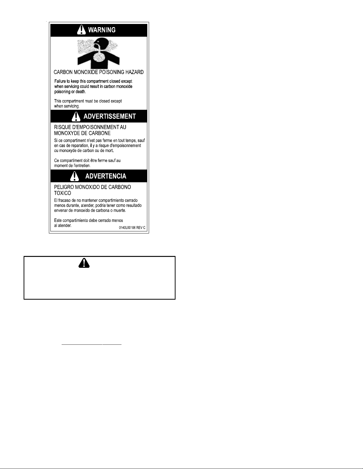
WARNING
TO
PREVENT PROPERTY DAMAGE, PERSONAL INJURY OR DEATH DUE TO
FIRE, EXPLOSION S, SMOKE, SOOT, COND E NSATION, ELECTRIC SHOCK OR
CARBON MONOXIDE, THIS UNIT MUST BE PROPERLY INSTALLED
REPAIRED, OPERATED AND MAINTAINED
.
This unit is approved for outdoor inst allation ONLY . Rated perf ormance is achieved aft er 72 hours of opera tion. Rated performance
is delivered at the specified airflow. See outdoor unit specification sheet for split system models or product specification sheet
for packaged and light commercial models. Specification sheets
can be found at www.daikinc omfort.com for Daikin brand products. Within the website, please select the residential or commercial products menu and then select the submenu for the type
of product to be installed, such as air conditioner s or heat pumps,
to access a list of product pages that each contain links to that
model’s specification sheet.
To assure that your unit operates safely and efficiently, it must be
installed, operated, and maintained in accordance with these installation and operating instructions, all local bui lding codes and
ordinances, or in their absence, with the latest edition of the National Fuel Gas Code NFPA54/ANSI Z223.1 and National Standard
of Canada CAN/CSA B149 Installation Codes.
,
American National Standards Institute
1430 Broadway
New York, NY 10018
System design and installation should also, where applicable, follow information pre sented in accept ed industry guides such as the
ASHRAE Handbooks. The manufacturer assumes no r esponsibility
for equipment installed in viola tion of an y c ode or r egula tion. The
mechanical installation of the packaged roof top units consists of
making final connections between the unit and building services;
supply and return duct connections; and drain connections (if required). The internal systems of the unit are completely factoryinstalled and tested prior to shipment.
Units are g ener ally ins t alled on a steel roof mounting curb assembly which has been shipped to the job site for installation on the
roof structure prior to the arrival of the unit. The model number
shown on the unit’s identification plate iden tifies the various components of the unit such as refrigeration tonnage, heating input
and voltage.
Carefully inspect the unit for damage including damage to the
cabinetry . Any bolt s or screws which ma y have loosened in tr ansit
must be re-tightened. In the even t of damage, the receiver should:
1. Make notation on delivery receipt of any visible damage
to shipment or container.
2. Notify carrier promptly and request an inspection.
3. In case of concealed damage, c arrier should be notified as
soon as possible-preferably within 5 days.
4. File the claim with the following supporting documents:
a. Original Bill of Lading, certified copy , or indemnity bond.
b. Original paid freight bill or indemnity in lieu thereof.
3
c. Original invoice or certified copy thereof, showing trade
and other discounts or reductions.
d. Copy of the inspection report issued by carrier
representative at the time damage is reported to the
carrier. The carrier is responsible for making prompt
inspection of damage and for a thorough investigation
of each claim. The distributor or manufacturer will not
accept claims from dealers for transportation damage.
NOTE: When inspecting the unit for transportation damage, remove all packaging materials. R ecycle or dispose of the pack aging
material according to local codes.
PRE-INSTALLATION CHECKS
Carefully rea d all instructions for the ins tallation prior t o installing
unit. Ensure each step or proce dur e is under stood and an y special
considerations are taken into account before starting installation.
Assemble all tools, hardware and supplies nee ded to complet e the
installation. Some items may need to be purchased locally.
UNIT LOCA TION
WARNING
TO
PREVENT POSSIBLE EQUIPM EN T DAMAGE, PROPERTY DAMAGE
PERSONAL INJURY OR DEATH, THE FOLLOWING BULLET POINTS MUST BE
OBSERVED WHEN INSTALLING THE UNIT
IMPORTANT NOTE: Remove wood shipping rails and metal ship-
ping brace (if applicable) prior to installation of the unit on a roof
curb.
.
,
• To avoid possible corrosion of the heat exchanger, do not
locate the unit in an area where the outdoor air (i.e.
combustion air for the unit) will be frequently
contaminated by compounds containing chlorine or
fluorine. Common sources of such compounds include
swimming pool chemicals and chlorine bleaches, paint
stripper , adhesives, p aints, varnishe s, sealers, wax es (which
are not yet dried) and solvents used during construction
and remodeling. Various commercial and industrial
processes may also be sources of chlorine/fluorine
compounds.
• T o avoid possible illness or death of the building occupant s,
do NOT locate outside air intake device (economizer,
manual fresh air intake, motorized fresh air intake) too
close to an exhaust outlet, gas vent termination, or
plumbing vent outlet. For specific distances required,
consult local codes.
• Allow minimum clearances from the enclosure for fire
protection, proper opera tion, and service access (see unit
clearances). These clearances must be permanently
maintained.
• The combustion air inlet and flue outlet on the unit must
never be obstructe d. If used, do not allow the economizer/
manual fresh air damper/ motorized fresh air damper to
become blocked by snow or debris. In some climates or
locations, it may be necessary to elev at e the unit to avoid
these problems.
• When the unit is heating, the temperature of the return
air entering the unit must be between 50° F and 100° F.
ALL INSTALLATIONS:
IMPORTANT NOTE: Unit should be energized 24 hours prior to
compressor start up to ensure crankcase heater has sufficiently warmed the compressors. Compressor damage may
occur if this step is not followed.
NOTE: Appliance is shipped from factory for vertical duct
application.
Proper installation of the unit ensure s tr ouble-free operation. Improper installation can result in problems ranging from noisy
operation to property or equipment damages, dangerous conditions that could result in injury or personal property damage and
could void the warranty. Give this booklet to the user and explain
it’s provisions. The user should r etain these ins tructions for futur e
reference.
• For proper flame pattern within the heat exchanger and
proper condensate drainage, the unit must be mounted
level.
• The flue outlet must be at least 12 inches fr om any opening
through which flue gases could enter a building, and at
least three feet above any forced air inlet located within
ten feet. The economizer/manual fresh air intake/
motorized fresh air intake and combustion air inlet
mounted on the unit are not affected by this restriction.
GROUND LEVEL INSTALLATIONS ONLY:
• When the unit is installed on the ground adjacent to the
building, a level concrete (or equal) base is recommended .
Prepare a base that is 3” larger than the package unit
footprint and a minimum of 3” thick.
• The base should also be located where no runof f of wa ter
from higher ground can collect in the unit.
ROOF TOP INSTALLATIONS ONLY:
• To avoid possible property damage or personal injury , the
roof must have sufficient structural strength to carry the
weight of the unit(s) and snow or water loads as required
by local codes. Consult a structur al engineer to determine
the weight capabilities of the roof.
• The unit may be installed directly on wood floors or on
Class A, Class B, or Class C roof covering material.
• To avoid possible personal injury, a safe, flat surface for
service personnel should be provided.
• As indicated on the unit data plate, a minimum clearance
of 36” to any combusti ble material is required on the
furnace access side of the unit. All combustible materials
must be kept out of this area.
• This 36” clearance must also be maintained to insure
proper combustion air and flue gas flo w. The combustion
air intake and furnace flue dischar ge mus t not be block ed
for any reason, including blockage by snow.
4
• Adequate clearances from the furnace flue discharge to
any adjacent public walkwa ys, adjacent buildings, building
openings or openable windows must be maintained in
accordance with the latest edition of the Na tional Fuel Gas
Code (ANSI Z223.1)
• Minimum horizontal clearance of 48” from the furnace
flue discharge to any electric met ers, gas meter s, regulators
and relief equipment is required.
UNIT PRECAUTIONS
• Do not stand or walk on the unit.
• Do not drill holes anywhere in panels or in the base fr ame
of the unit except where indicated. Unit access panels
provide structural support.
• Do not remove any access panels until unit has been
installed on roof curb or field supplied structure.
• Do not roll unit across finished roof without prior approval
of owner or architect.
• Do not skid or slide on any surface as this may damage
unit base. The unit must be store d on a flat, level surf ace.
Protect the condenser coil because it is easily damaged.
ROOF CURB INSTALLATIONS ONLY:
Curb installations must c omply with local codes and should be done
in accordance with the est ablished guidelines of the National R oofing Contractors Association.
NOTE: The unit and curb accessories ar e designed to allow v ertical
duct installation before unit placement. Duct inst allation after unit
placement is not recommended.
CAUTION
ALL
CURBS LOOK SIMILAR
CHECK JOB PLANS CAREFULLY AND VERIFY MARKINGS ON CURB
ASSEMBLY
INFORMATIO N SHOWN
. I
NSTRUCTIONS MAY VARY IN CURB STYLES AND SUPERCEDE
. TO
AVOID INCORRECT CURB POSITIONING
.
,
See the manual shipped with the roof curb for assembly and installation instructions.
CLEARANCES
36”
Min.*
36”*
Min.
36” Min.*
Proper unit installation requires that the roof curb be firmly and
permanently attached to the roof structure. Check for adequate
fastening method prior to setting the unit on the curb.
Full perimeter roof curbs are available from the factory and are
shipped unassembled. Field assembly, squaring, leveling and
mounting on the roof structure are the responsibility of the installing contractor. All required hardware necessary for the assembly of the sheet metal curb is included in the curb accessory.
WARNING
TO
PREVENT POSSIBLE EQUIPM EN T DAMAGE, PROPERTY DAMAGE
PERSONAL INJURY OR DEATH, THE FOLLOWING BULLET POINTS MUST BE
OBSERVED WHEN INSTALLING THE UNIT
.
,
• Sufficient structural support mus t be determined prior to
locating and mounting the curb and package unit.
• Ductwork must be constructed using industry guidelines.
The duct work must be placed into the roof curb befo re
mounting the package unit. Our full perimeter curbs
include duct connection frames to be assemble d with the
curb. Cantilevered type curbs are not available from the
factory.
• Curb insulation, cant strips, flashing and general roofing
material are furnished by the contractor.
The curbs must be supported on parallel sides by roof members.
The roof members must not penetrate supply and return duct
opening areas as damage to the unit might occur.
*In situations that have multiple units, a 48” minimum clearance
is required between the condenser coils.
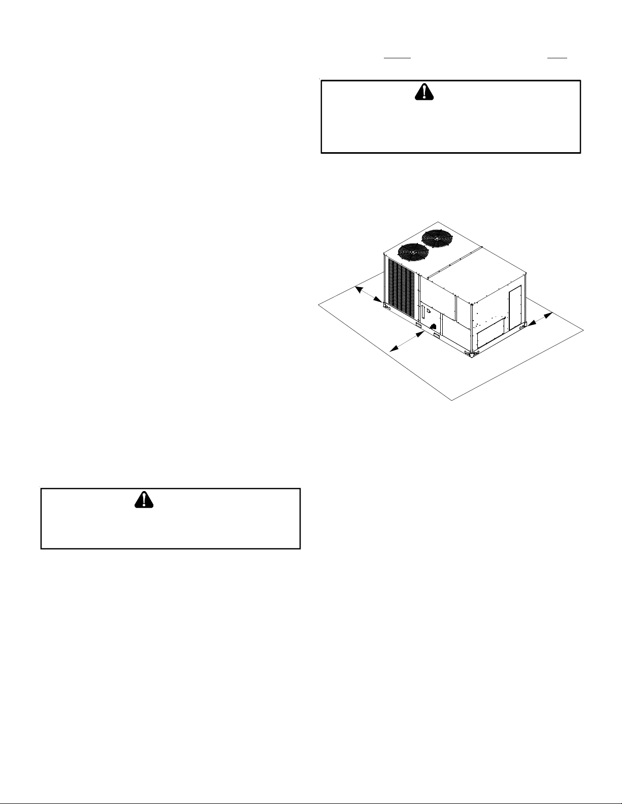
UNIT CLEARANCES
Adequate clearance around the unit should be k ept f or safe ty , ser vice, maintenance, and proper unit operation. A total clearance
of 75” on the main control panel side of the unit is r ecommende d
to facilitate possible fan shaft, coil, electric heat and gas furnace
removal. A clear ance of 48” is rec ommended on all other side s of
the unit to facilitate possible compressor removal, to allow service access and to insure proper ventilation and condenser airflow. The unit must not be installe d beneath an y obstruction. The
unit should be installed remote from all building exhausts to inhibit ingestion of exhaust air into the unit fresh air intake.
NOTE: If the 48” minimum is used on the control panel side of a
DCG unit, a flue extension (MF# 220-GX-02) needs be to installed
to prevent flue gas recirculation.
5
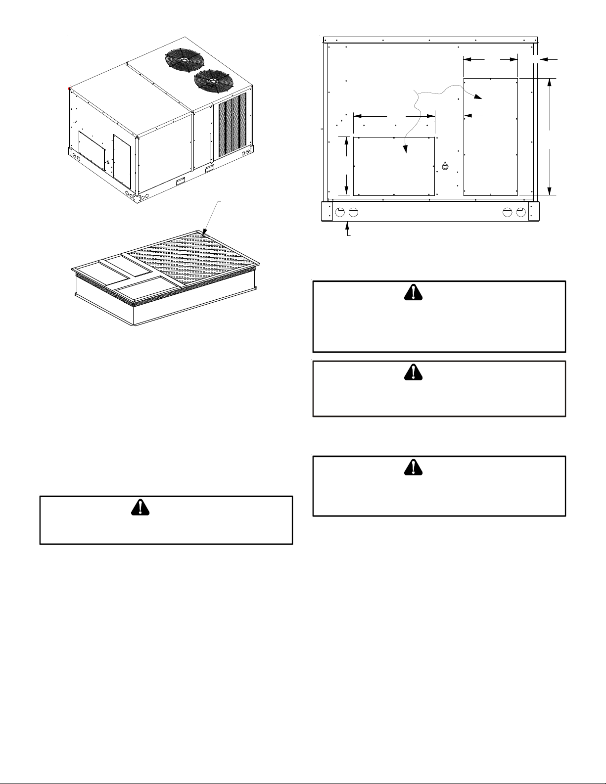
REMOVE
COVERS
17” 7 3/8”
11” 4 7/8””
25”
INSULATED
PANELS
ROOF CURB INSTALLATION
ROOF CURB POST -INSTALLA TION CHECKS
After installation, check the top of the curb, duct connection fr ame
and duct flanges to make sure gasket has been applied properly.
Gasket should be firmly applied to the top of the curb perimeter,
duct flanges and any exposed duct connection frame. If gasket is
loose, re-apply using strong weather resistant adhesive.
PROTRUSION
Inspect curb to ensure that none of the utility services (electric)
routed through the curb protrude above the curb.
CAUTION
IF
PROTRUSIONS EXIST, DO NOT ATTEM PT TO SET UNIT ON CURB
NFORMATION SHOWN
I
.
.
ROOF TOP DUCT CONNECTIONS
Install all duct connections on the unit before placing the unit on
rooftop.
HORIZONTAL DISCHARGE
Refer t o IOD-7006 included in the litera ture pack for inst alling horizontal duct covers.
Flexible duct connectors between the unit and ducts are recommended. Insulate and weatherproof all ex ternal ductwork and
joints as required and in accordance with local codes.
12”
SUPPL Y
6 3/16”
HORIZONTAL DISCHARGE DUCT CONNECTIONS
RIGGING DET AILS
WARNING
TO
PREVENT PROPERTY DAMAGE, THE UNIT SHOULD REMA IN IN AN
UPRIGHT POSITION DURING ALL RIGGING AND MOVING OPERATIONS
T
O FACILITATE LIFTING AND MOVING WHEN A CRANE IS USED, PLACE
THE UNIT IN AN ADEQU ATE CABLE SLING
.
.
CAUTION
DO
NOT LIFT UNITS TWO AT A TIME
INCLUDED IN THE UNIT BASE FRAME
PREVENT DAMAGE TO THE UNIT
. P
ROVISIONS FOR FORKS HAVE BEEN
. M
INIMUM FORK LENGTH IS
.
48” TO
Provisions for fork s have been include d in the unit base frame. No
other fork locations are approved.
WARNING
TO
PREVENT POSSIBLE EQUIPM EN T DAMAGE, PROPERTY DAMAGE
PERSONAL INJURY OR DEATH, THE FOLLOWING BULLET POINTS MUST BE
OBSERVED WHEN INSTALLING THE UNIT
.
,
• Unit must be lifted by the four lifting holes located at the
base frame corners.
• Lifting cables should be at tached to the unit with shackle s.
• The distance between the crane hook and the top of the
unit must not be less than 60”.
• Two spreader bars must span over the unit to prevent
damage to the cabinet by the lift cables. Spreader bars
must be of sufficient length so that cables do not come in
contact with the unit during transport. Remove wood
struts mounted beneath unit base frame before setting
unit on roof curb. These struts are intended to protect
unit base frame from fork lift damage. Removal is
accomplished by extracting the sheet met al r etainer s and
pulling the struts through the base of the unit. Refer to
rigging label on the unit.
6
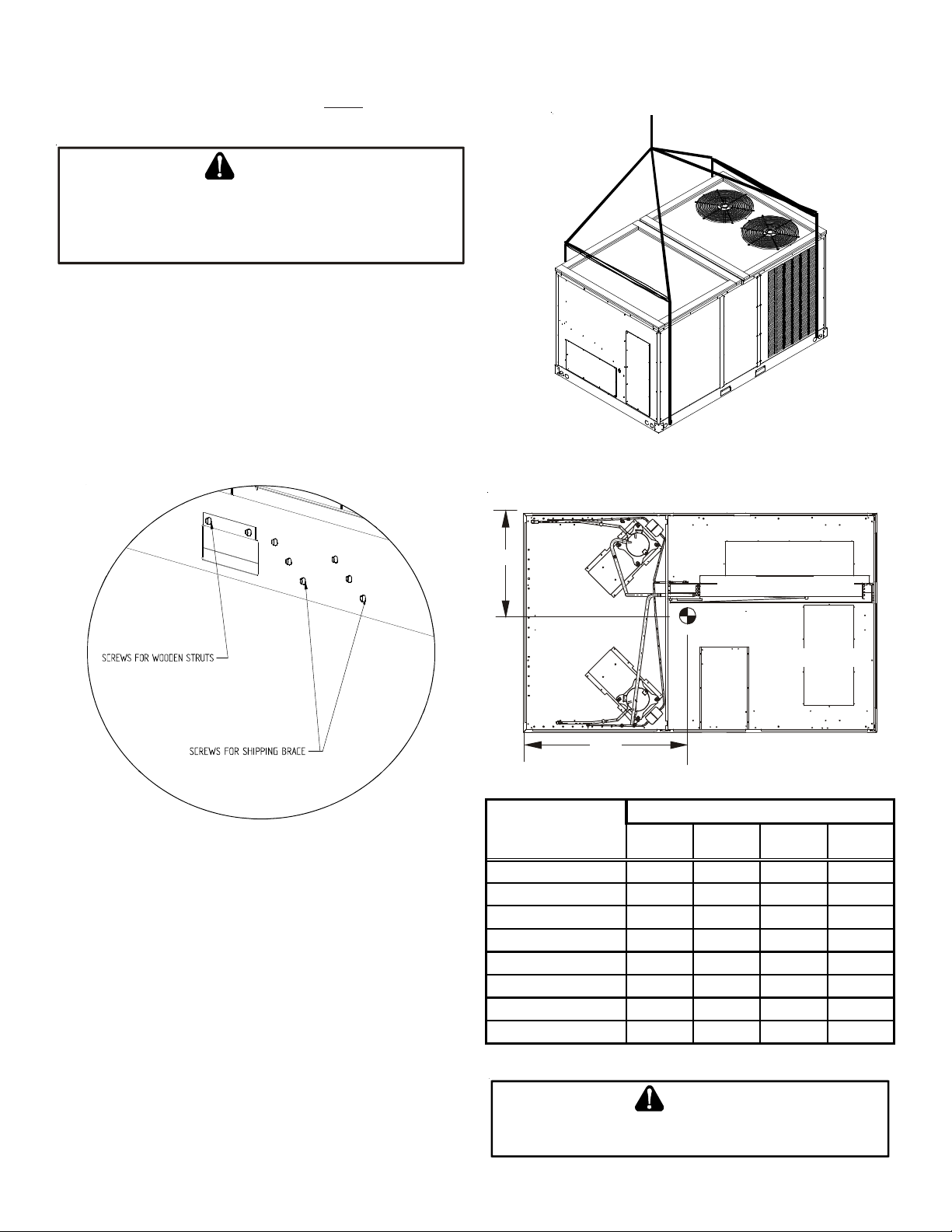
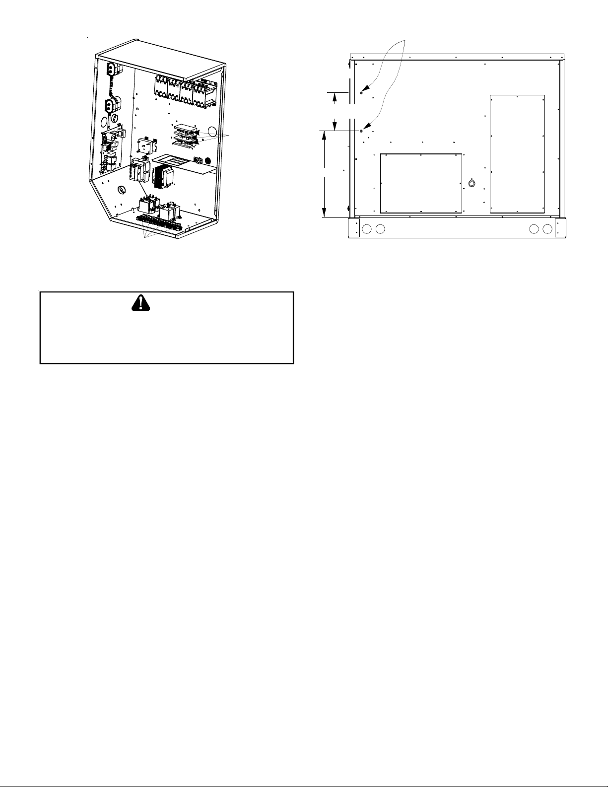
• Your unit may be equipped with a steel shipping brace
located underneath the unit (under compressors). If
installing on a roof curb, the brace MUST be removed.
Follow the following instructions for removal.
CAUTION
W
HEN UNIT IS SUSPENDED, BOARDS AND SHIPPING BRACE WILL DROP WHEN
SCREWS ARE REMOVED
EMOVE FORK HOLE BRACKETS, BOARDS AND SHIPPING BRACE FROM BOTTOM
R
UNIT BEFORE PLACING UNIT ONTO CURB
OF
Before installing this unit on a roof curb:
1. Remove wooden strut s per installation instructions. These
are the struts that are located in the fork holes and are
used to protect the unit from damage while lifting with
forks.
2. Locate and remove the twelve (12) scr ews tha t at t ach the
shipping brace to the side rails. There will be six (6) screws
on each side of the unit and they are in a diagonal pattern.
See following figure.
. TO
PREVENT PERSONAL INJURY
, STAND CLEAR.
.
Lower unit carefully onto roof mounting curb. While rigging unit,
center of gravity will cause condenser end t o be lower than supply
air end.
To assist in determining rigging requirements, unit weights are
shown as follows:
3. Lift unit per the “Rigging Details” section of the installation
instructions, observing all warnings and cautions. Lift the
unit high enough off the ground to reach under and gra sp
the shipping brace.
4. Rotate the brace by tapping the ends until the brace falls
free from the unit.
5. Dispose of the brace appropriately.
Important: If using bottom discharge with roof curb, ductwork
should be attached to the curb prior t o installing the unit. Ductwork
dimensions are shown in Roof Curb Installation Instructions.
A
Y
RETURN
C
EVAPORATOR COIL
COMPRESSOR 1
CG
COMPRESSOR 2
SUPPLY
BD
DATA
Corner Weight - A 269 255 255 335
Corner Weight - B 297 321 321 390
Corner Weight - C 254 250 250 295
Corner Weight - D 280 314 314 345
Unit Shipping Weight 1175 1215 1215 1390
Unit Operating Weight 1100 1140 1140 1365
X (Inches) 48 49 49
Y (Inches) 32 34 34
X
CORNER & CENTER OF GRAVITY LOCATIONS
DCG Weights (lbs)
090 102 120 150
47
33.5
Refer to the Roof Curb Installation Instructions for proper curb
installation. Curbing must be installed in compliance with the National Roofing Contractors Association Manual.
CAUTION
TO
PREVENT SEVERE DAMAGE TO THE BOTTOM OF THE UNIT, DO NOT
FORK LIFT UNIT AFTER WOOD STRUTS HAVE BEEN REMOVED
7
.
Bring condenser end of unit into alignment with the curb. With
condenser end of the unit resting on curb member and using curb
as a fulcrum, lower opposite end of the unit until entire unit is
seated on the curb. When a rectangular cantilever curb is used,
care should be taken to center the unit. Check for proper alignment and orientation of supply and return openings with duct.
The main power supply wiring to the unit and low voltage wiring
to accessory controls must be done in accordance with these instructions, the latest edition of the Na tional Electrical Code (ANSI/
NFP A 7 0), and all local codes and ordinances. All field wiring shall
conform with the temperature limitations for Type T wire (63°F/
35°C rise).
RIGGING REMOVAL
CAUTION
TO
PREVENT DAMAGE TO THE UNIT, DO NOT ALLOW CRANE HOOKS AND
SPREADER BARS TO REST ON THE ROOF OF THE UNIT
.
Remove sprea der bars, lifting cable s and other rigging equipment.
ELECTRICAL WIRING
WARNING
HIGH VOLTAGE !
D
ISCONNECT ALL POWER BEFORE SERVICING OR
INSTALLING THIS UNIT
BE PRESENT
DAMAGE, PERSONAL INJURY OR DEATH
. F
. M
ULTIPLE POWER SOURCES MAY
AILURE TO DO SO MAY CAUSE PROPERTY
.
WARNING
HIGH VOLTAGE !
TO
AVOID PERSONAL INJURY OR DEATH DUE TO ELECTRICAL
SHOCK, DO NOT TAMPER WITH FACTORY WIRING
INTERNAL POWER AND CONTROL WIRING OF THESE UNITS
ARE FACTORY-INSTALLED AND HAVE BEEN THOROUGHLY
TEST PRIOR TO SHIPMENT
REPRESENTATIVE IF ASSISTANCE IS REQUIRED
. C
ONTACT YOUR LOCAL
. THE
.
CAUTION
TO
PREVENT DAMAGE TO THE WIRING, PROTECT WIRING FROM SHARP
EDGES
. F
OLLOW NATIONAL ELECTRICAL CODE AND ALL LOCAL CODES
AND ORDINANCES
ACCESS PANELS
. DO
NOT ROUT E WIRES THROUGH REMOVABLE
.
CAUTION
C
ONDUIT AND FITTINGS MUST BE WEATHER-TIGHT TO PREVENT WATER
ENTRY INTO THE BUILDING
.
For unit protection, use a fuse or HACR circuit breaker that is in
excess of the circuit ampacity, but less than or equal to the maximum overcurrent protection device. DO NOT EXCEED THE MAXIMUM OVERCURRENT DEVICE SIZE SHOWN ON UNIT DATA PLATE.
The main power supply shall be three-phase, three wir e. The unit
is factory wired for the voltage shown on the unit’s data plate.
NOTE: If supply voltage is 208V, all leads on primary of transformer
TRANS1 must be moved from the 230V to the 208V tap.
Main power wiring should be sized f or the minimum wire ampacity
shown on the unit’s database. Size wires in accordance with the
ampacity tables in Article 310 of the National Electrical Code. If
long wires are required, it may be necessary to increase the wire
size to prevent e xce ssive volt age drop. Wires should be sized f or a
maximum of 3% voltage drop.
CAUTION
TO
AVOID PROPERTY DAMAGE OR PERSONAL INJURY DUE TO FIRE, USE
ONLY COPPER CONDUCTORS
.
CAUTION
TO
PREVENT IMPROPER AND DANGEROUS OPERATION DUE TO WIRING
ERRO RS, LABEL ALL WIRES PRIOR TO DISCONNECTION WHEN SERVICING
CONTROLS
. V
ERIFY PROPER OPERATION AFTER SERVICING
.
NOTE: A weather-tight disconnect switch, properly sized for the
unit total load, must be field or f actory inst alled. An e xt ernal field
supplied disconnect may be mounted on the exterior panel.
Ensure the data plate is not covered by the field-supplied
disconnect switch.
• Some disconnect switches are not fused. Protect the
power leads a t the point of distribution in accordance with
the unit data plate.
• The unit must be electrically grounded in accor dance with
local codes or, in the absence of local codes, with the lates t
edition of the National Electrical Code (ANSI-NFPA 70). A
ground lug is provided for this purpose. Size grounding
conductor in accordance with T able 250-95 of the National
Electrical Code. Do not use the ground lug for c onnecting
a neutral conductor.
• Connect power wiring to the middle contactor within the
main control box or to electric al power block if equipped.
All line voltage connections must be made through weatherproof
fittings. All exterior power supply and ground wiring must be in
approved weatherproof conduit.
8
10 3/16”
DIMPLES MARK DRILL LOCATIONS
HIGH VOLTAGE ENTRANCE
Power
Wiring
Thermostat Wiring
POWER AND LOW VOLTAGE BLOCK LOCATIONS
WARNING
F
AILURE OF UNIT DUE TO OPERATION ON IMPROPER LINE VOLTAG E OR
WITH EXCESSIVE PHASE UNBALANCE CONST I TUTES PRODUCT ABUSE AND
WILL VOID YOUR WARRANTY AND MAY CAUSE SEVERE DAMAGE TO THE
UNIT ELECTRICAL COMPONENTS
.
AREAS WITHOUT CONVENIENCE OUTLET
It is recommended that an independent 115V power source be
brought to the vicinity of the roof top unit for portable lights and
tools used by the service mechanic.
NOTE: Refer to local codes for requirements. These outlets can
also be factory installed.
UNITS INSTALLED ON ROOF TOPS
Main power and low voltage wiring may enter the unit through
the side or through the roof curb. Install conduit connectors at
the desired entrance locations. External connectors must be
weatherproof. All holes in the unit base must be sealed (including
those around conduit nuts) to prevent water leakage into building. All required conduit and fittings are to be field supplied.
Supply voltage to roof top unit mus t not vary by more than 10% of
the value indicated on the unit data plate. Phase voltage unbalance must not exceed 2%. Contact your local power company for
correction of improper voltage or phase unbalance.
LOW VOLTAGE ENTRANCE
26 ½”
ELECTRICAL ENTRANCE LOCATIONS
Unit is equipped with a Low Voltage T erminal Block and has Single
Point wiring to the contactor.
LOW VOLTAGE CONTROL WIRING
1. A 24V thermostat must be installed for unit operation. It
may be purchased with the unit or field -supplied.
Thermostats may be programmable or electromechanical
as required.
2. Locate thermostat or remote sensor in the conditioned
space where it will sense average temperature. Do not
locate the device where it may be directly exposed to
supply air, sunlight or other sources of heat. Follow
installation instructions packaged with the thermostat.
3. Use #18 AWG wire for 24V control wiring runs not
exceeding 75 feet. U se #16 A WG wire for 24V con trol wiring
runs not exceeding 125 feet. Use #14 AWG wire for 24V
control wiring runs not exceeding 200 feet. Low voltage
wiring may be National Electrical Code (NEC) Class 2 wher e
permitted by local codes.
4. Route thermostat wires from sub-base terminals to the
unit. Control wiring should enter through the duct panel
(dimple marks entrance location) or thr ough the roof curb.
Connect thermostat and any accessory wiring to low
voltage terminal block TB1 in the main control box.
NOTE: Field-supplied conduit may need to be installed depending
on unit/curb configuration. Use #18 AWG solid conductor wire
whenever connecting thermostat wire s to t erminals on sub-base.
DO NOT use larger than #18 AWG wire. A transition to #18 AWG
wire may be requir e d be fore entering thermostat sub-base.
NOTE: Refer to unit wiring diagrams for thermostat hookups.
9
GAS SUPPLY PIPING
Natural Gas Connection
WARNING
TO
PREVENT PERSONAL INJURY OR DEATH DUE TO IMPROPER
INSTALLATION, ADJUSTMENT, ALTERA TI ON, SERVICE OR MAINTENANCE
REFER TO THIS MANUAL
INFORMATIO N, CONSULT A QUALIFIED INSTALLER, SERVICE AGENCY OR
THE GAS SUPPLIER
. FOR
ADDITIONAL ASSISTANCE OR
.
,
IMPORTANT NOTE: This unit is factory set to operate on natural
gas at the altitudes shown on the rating plate.
WARNING
TO
PREVENT PROPERTY DAMAGE, PERSONAL INJURY OR DEATH WHEN
EITHER USING PROPANE GAS ALONE OR AT HIGHER ALTITUDES, OBTAIN
AND INSTALL THE PROPER CONVERSION KIT(S
RESU LT IN UNSATISFACTORY OPERATION AND/OR EQUIPMEN T DAMAGE
IGH ALTITUDE KITS ARE FOR
H
APPROVED FOR USE IN CANADA
U.S. I
.
). F
AILURE TO DO SO CAN
NSTALLATIONS ONLY AND ARE NOT
.
The rating plate is stamped with the model number, type of gas
and gas input rating. Mak e sure the unit is equippe d to oper ate on
the type of gas available. Conver sion to propane (LP) g as is permitted with the use of the factory authorized conversion kit (see the
unit Technical Manual for the appropriate kit). For High Altitude
derates, refer to the latest edition of the National Fuel Gas Code
NFPA 54/ANSI Z223.1.
INLE T GAS PRESSURE
NATURAL M i n. 5.0" W .C ., Ma x . 10.0" W.C.
PROPANE Min. 1 1.0 " W. C., M ax . 14.0" W.C.
Inlet Gas Pressure Must Not Exceed the Maximum Value Shown in Table Above.
The minimum supply pressure should not vary from that shown in
the table above because this could prevent the unit from having
dependable ignition. In addition, gas input to the burners must
not exceed the rated input shown on the rating plate. Overfiring
of the unit could result in premature heat exchanger failure.
PIPING
IMPORTANT NOTE: To avoid possible unsatisfactory operation or
equipment damage due to under firing of equipment, do not undersize the natur al/propane gas piping fr om the meter/tank to the
unit. When sizing a trunk line, include all appliances on that line
that could be operated simultaneously.
The rating plate is stamped with the model number, type of gas
and gas input rating. Mak e sure the unit is equippe d to oper ate on
the type of gas available. The gas line installation must comply
with local codes, or in the absence of local codes, with the latest
edition of the National Fuel Gas Code NFPA 54/ANSI Z223.1.
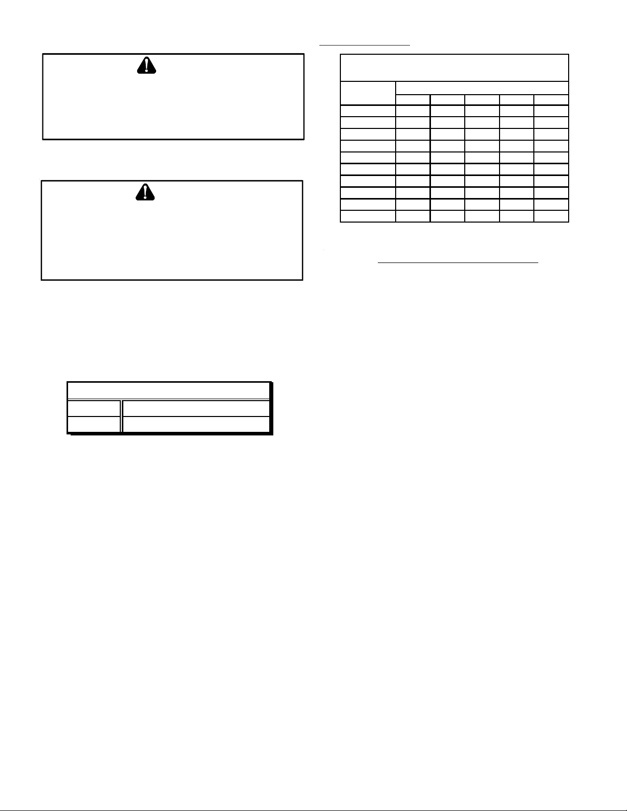
Natural Gas Capacity of Pipe
in Cubic Feet of Gas Per Hour (CFH)
Length of
Pipe in Feet
10 132 278 520 1050 1600
20 92 190 350 730 1100
30 73 152 285 590 980
40 63 130 245 500 760
50 56 115 215 440 670
60 50 105 195 400 610
70 46 96 180 370 560
80 43 90 170 350 530
90 40 84 160 320 490
100 38 79 150 305 460
Pressure= .50 PSIG or less and Pressure Drop of 0.3" W.C.
(Based on 0.60 Specific Gravity Gas)
CFH =
Nominal Black Pipe Size (inches)
1/2 3/4 1 1 1/4 1 1 /2
BTUH Furnace Input
Heatin g Valu e of Gas (BTU/Cubic Foot)
Refer to the Proper Piping Practice drawing for the gener al layout
at the unit. The following rules apply:
1. Use black iron pipe and fittings for the supply piping. The
use of a flex connector and/or copper piping is permitted
as long as it is in agreement with local codes.
2. Use pipe joint compound on male thre a ds only. Pipe joint
compound must be resis tant to the action of the fuel used.
3. Use ground joint unions.
4. Install a drip leg to trap dirt and moisture before it can
enter the gas valve. The drip leg must be a minimum of
three inches long.
5. Use two pipe wrenches when making connection to the
gas valve to keep it from turning.
6. Install a manual shut-off valve in a convenient location
(within six feet of unit) between the meter and the unit.
7. Tighten all joints securely.
8. The unit must be connected to the building piping by one
of the following methods:
• Rigid metallic pipe and fittings
• Semirigid metallic tubing and metallic fittings (Aluminum
alloy tubing must not be used in exterior locations)
• Listed ga s appliance c onnector s used in acc or dance with
the terms of their listing that are complet ely in the same
room as the equipment
• In the prior two methods above the connector or tubing
must be protected from physical and thermal damage.
Aluminum alloy tubing and connectors must be coated
to protect agains t external corrosion when in cont act with
masonry, pla st er or insula tion or are subject t o r epe ate d
wettings by liquids (wat er - not rain w at er, detergents or
sewage).
10
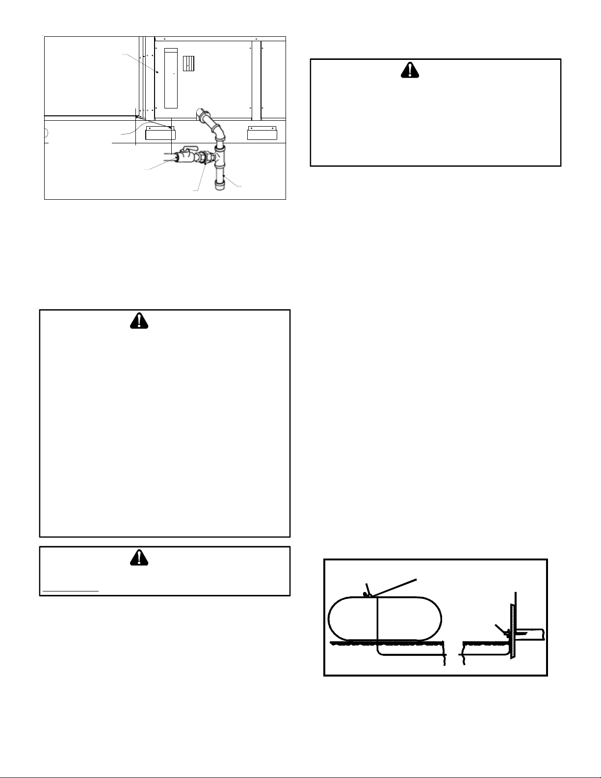
DOOR
PROVIDE CLEARANCE
FOR REMOVAL OF
ACCESS PANELS
MANUAL
SHUTOFF VALVE
GROUND JOINT
UNION
DRIP LEG
PROP ANE GAS INSTALLA TIONS
WARNING
TO
AVOID PROPERTY DAMAGE, PERSONAL INJURY OR DEATH DUE TO
FIRE OR EXPLOSION CAUSED BY A PROPANE GAS LEAK, INSTALL A GAS
DETECTING WARNING DEVICE
ODORANT IN PROPANE GAS, A GAS DETECTING WARNING DEVICE IS THE
ONLY RELIABLE WAY TO DETECT A PROPANE GAS LEAK
LOCAL PROPANE GAS SUPPLIER ABOUT INSTALLING A GAS DETECTING
WARNING DEVICE
.
. S
INCE RUST CAN REDUCE THE LEVEL OF
. C
ONTACT A
IMPORTANT NOTE: Propane gas conversion kit s must be installed
to convert units to propane gas.
PROPER PIPING PRACTICE
NOTE: The unit gas supply entrance is factory sealed with plugs.
Keep plugs in place until gas supply is ready to be installed. Once
ready, replace the plugs with the supplied grommets and install
gas supply line.
GAS PIPING CHECKS
CAUTION
TO
PREVENT PROPERTY DAMAGE OR PERSONAL INJURY DUE TO FIRE
THE FOLLOWING INSTRUCTIONS MUST BE PERFORMED REGARDING GAS
CONNECTIONS AND PRESSURE TESTING
• T
HE UNIT AND ITS GAS CONNECTIONS MUST BE LEAK TESTED
BEFORE PLACING IN OPERATION
EXPLOSION OR FIRE, NEVER USE A MATCH OR OPEN FLAME TO TEST
FOR LEAKS
H
OVERFIRING WHICH MAY RESU LT IN PREMATURE HEAT EXCHANGE
FAILURE
• T
HIS UNIT AND ITS SHUT-OFF VALVE MUST BE DISCONNECTED FROM
THE GAS SUPPLY DURING ANY PRESSURE TESTING OF THAT SYSTEM
AT TEST PRESSURES IN EXCESS OF
HIS UNIT MUST BE ISOLATED FROM THE GAS SUPPLY SYSTEM BY
• T
CLOSING ITS MANUAL SHUT-OFF VALVE DURING ANY PRESSURE
TESTING OF THE GAS SUPPLY PIPING SYSTEM AT TEST PRESSURES
EQUAL TO OR LESS THAN
. N
EVER EXCEED SPECIFIED PRESSURES FOR TESTING
IGHER PRESSURE MAY DAMAGE GAS VALVE AND CAUSE
.
1/2 P SIG (3.48 KPA).
:
. B
ECAUSE OF THE DANGER OF
1/2 P SIG (3.48 KPA).
WARNING
TO
AVOID PROPERTY DAMAGE OR PERSONAL INJURY, BE SURE THERE IS
NO OPEN FLAME
IN THE VICINITY DURING AIR BLEEDING
.
,
.
All propane gas equipment must conform to the safety standards
of the National Board of Fire Underwriter s (See NBFU Manual 58).
Line pressure 11.3 - 14” w.c.
For satisfactory operation, propane gas manifold pressure must
be within 9.7 - 10.3 inches w.c. for high fire and within 6.7 - 7.3
inches w.c. low fire at the manifold with all gas appliances in operation. Maintaining proper gas pressure depends on three main
factors:
1. Vaporization rate, which depends on (a) temperature of
the liquid, and (b) wetted surface ar ea of the co ntainer or
containers.
2. Proper pressure regulation.
3. Pressure drop in lines between regulators, and between
second stage regulator and the appliance. Pipe size
required will depend on length of pipe run and total load
of all appliances.
TANKS AND PIPING
Complete information re garding tank sizing for vaporization,
recommended regulator settings and pipe sizing is available
from most regulat or manufacturers and pr opane gas suppliers .
Since propane gas will quickly dissolve white lead or most
standard commer cial compounds, special pipe dope must be
used. Shellac base compounds resistant to the actions of
liquefied petroleum ga ses such as Gasolac®, Stalactic®, Clyde’ s
or John Crane® are satisfactory.
See the following figure for typical propane gas piping.
First Stage
Regulator
5 to 15 PSIG
(20 PSIG Max.)
Continuous
11" W.C.
®
There will be air in the gas supply line after testing for leaks on a
new installation. Therefore, the air must be bled from the line by
loosening the ground joint union until pure ga s is expelled. Tighten
union and wait for five minutes until all ga s ha s been dissipa t ed in
the air. Be certain there is no open flame in the vicinity during air
bleeding procedure. The unit is placed in operation by closing the
main electrical disconnect switch for the unit.
11
200 PSIG
Maximum
TYPICAL PROPANE GAS PIPING
Second Stage
Regulator
ROOF TOP LOCATION AND INSTALLATION
The gas supply piping location and installation for roof top units
must be in accordance with local codes or, in the absence of locals
codes, with ordinances of the latest edition of the National Fuel
Gas Code (ANSI Z223.1).
A manual gas shut off valve must be field installed external to the
roof top unit. In addition, a drip leg must be installed near the
inlet connection. A ground joint union connection is required between the external shut off valve and the unit connection to the
gas valve to permit removal of the burner assembly for servicing.
1. Route gas piping to unit so that it does not interfere with
the removal of access panels. Support and align piping to
prevent strains or misalignmen t of the manifold assembly .
2. All units are furnished with standard female NPT pipe
connections. Connection pipe sizes for DCG090 through
300 units is 3/4" NPT The size of the gas supply piping to
the unit must be based on length of run, number of units
on the system, gas characteristics, BTU requirement and
available supply pressure. All piping must be done in
accordance with local codes or, in the absence of local
codes, with the lates t edition of the National Fuel Gas Code
(ANSI Z223.1).
NOTE: The gas connection size at the unit does NOT
establish the size of the supply line.
3. These units are designed for either natural or propane
(LP) gas and are specifically cons tructed at the factory for
only one of these fuels. The fuels are NO T interchangeable.
However, the furnace can be converted in the field from
natural gas to LP gas with the appropriate factory kit (see
unit Technical Manual for the appropriate kit). Only a
qualified contractor, experienced with natural and prop ane
gas systems, should attempt conversion. Kit instructions
must be followed closely to assure safe and reliable unit
operation.
4. With all units on a common line operating under full fire,
natural gas main supply pressure should be adjusted to
approximat ely 7.0" w.c., measured at the unit gas valv e. If
the gas pressur e at the unit is greater than 10.5" w.c., the
contractor must furnish and install an external type
positive shut off service pressure regulator. The unit will
not function satisfactorily if supply gas pr essure is less than
5.5" w.c. or greater than 10.5" w.c..
NOTE: A minimum horizontal dist ance of 48" between the
regulator and the furnace flue discharge is required.
5. With all units on a common line operating under full LP
gas main supply pressur e should be at lea st 11.0" w.c. and
must be no greater than 14.0" w.c., measured at the unit
gas valve. Unit will not function satisfactorily if supply gas
pressure is less than 11.0" w.c. or greater than 14.0" w .c..
6. All pipe connections should be sealed with a pipe thread
compound, which is resistant to the fuel used with the
furnace. A soapy water solution should be used to check
all joints for leaks. A 1/8" NPT plugged tap is located on
the entering side of the gas v alve for test g auge connection
to measure supply (main) gas pressure. Another 1/8" tap
is provided on the side of the manifold for checking
manifold pressure.
WARNING
T
HIS UNIT AND ITS INDIVIDUAL SHUTOFF VALVE MUST BE
DISCONNECTED
PRESSURE TESTING OF THAT SYSTEM AT TEST PRESSURES IN EXCESS OF
1/2 PSIG (13.8”
FROM THE GAS SUPPLY SYSTEM DURING ANY
W.C
.).
CAUTION
T
HIS UNIT MUST BE
BY CLOSING ITS INDIVIDUAL MANUAL SHUTOFF VALVE DURING ANY
PRESSURE TESTING EQUAL TO OR LESS THAN
ISOLATED
FROM THE GAS SUPPLY PIPING SYSTEM
1/2 P SIG.
7. There must be no obstruction to prevent the flow of
combustion and ventilating air. A vent stack is not requir ed
and must never be used. The power venter will supply an
adequate amount of combustion air as long as the air
passageways are kept free of any obstructions and the
recommended external unit clearances are maintained.
CIRCULA TING AIR AND FIL TERS
DUCTWORK
The supply duct should be provided with an access panel large
enough to inspect the air chamber downstream of the heat exchanger. A cover should be tightly attached to prevent air leaks.
Ductwork dimensions are shown in the roof curb installation
manual.
If desired, supply and return duct connections to the unit may be
made with flexible connections to reduce possible unit operating
sound transmission.
VENTING
NOTE: V enting is self-contained.
The inductor motor on DCG units is a dual voltage motor. It is factory
wired for 230 volt s. If field supply power is 208V , the ins taller must
swap the connections of the black and red leads (located in the
blower compartment) to ensure c orrect inductor mot or operation.
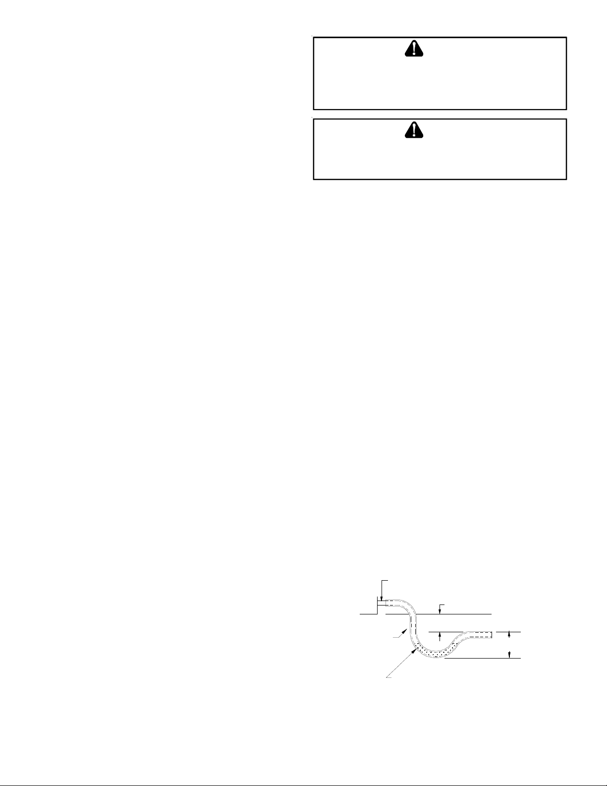
CONDENSA TE DRAIN CONNE CTION
CONDENSATE DRAIN CONNECTION
A 3/4” female NPT drain connection is supplied on the end of the
unit and bottom of the drain pan f or condensat e piping. An ext ernal trap must be installed for proper condensate drainage.
DRAIN
CONNECTION
UNIT 2" MINIMUM
FLEXIBLE
TUBING-HOSE
OR PIPE
A POSITIVE LIQUID
SEAL IS REQUIRED
DRAIN CONNECTION
Install condensate dr ain trap as shown. Use 3/4" drain line and fittings or larger. Do not operate without trap.
3" MIN IMUM
12
HORIZONTAL DRAIN
Drainage of condensate directly on to the r oof ma y be accept able;
refer to local code. It is recommended that a small drip pad of
either stone, mortar, wood or metal be provided to prevent any
possible damage to the roof.
and Checks procedure. The St artup, Adjustment s, and Checks procedure at outside ambients below 55°F should be limit ed to a readiness check of the refrigera tion system with the r equired final check
and calibration left to be completed when the outside ambient
rises above 55°F.
CLEANING
Due to the fact that drain pans in any air conditioning unit
will have some moisture in them, algae and fungus will
grow due to airborne bacteria and spores. Periodic cleaning is necessary to prevent this build-up from plugging the
drain.
ST ARTUP, ADJUSTMENTS, AND CHECKS
WARNING
HIGH VOLTAGE!
TO
AVOID PERSONAL INJURY OR DEATH DUE TO
ELECTRICAL SHOCK, BOND THE FRAME OF THIS UNIT TO
THE BUILDING ELECTRICAL GROUND BY USE OF THE
GROUNDING TERMINAL PROVIDED OR OTHER
ACCEPTABLE MEANS
SERVICING OR INSTALLING THIS UNIT
. D
ISCONNECT ALL POWER BEFORE
.
PRE-STARTUP INSTRUCTIONS - GENERAL
CAUTION
TO
PREVENT PROPERTY DAMAGE OR PERSONAL INJURY
THE UNIT UNTIL ALL NECESSARY PRE-CHECKS AND TEST HAVE BEEN
PERFORMED
Prior to the beginning of Startup, Adjustments, and Checks pr ocedures, the following steps should be completed in the building.
MOVING MACHINERY HAZARD!
T
O PREVENT POSSIBLE PERSONAL INJURY OR DEATH, DISCONNECT
POWER TO THE UNIT AND PADLOCK IN THE
SERVICING FANS
This unit is equipped with an electronic ignition device to automatically light the main burners. It also has a power vent blower
to exhaust combustion products.
On new installations, or if a major component has been replaced,
the operation of the unit must be checked.
Check unit operation as outlined in the following instructions. If
any sparking, odors, or unusual sounds are encountered, shut off
electrical power and recheck for wiring errors, or obstructions in
or near the blower motors. Duct cov er s must be removed before
operating unit.
The Startup, Adjustments, and Checks procedure provides a stepby-step sequence which, if follow ed, will assure the proper st artup
of the equipment in the minimum amount of time. Air balancing
of duct system is not considered part of this procedure. However,
it is an important phase of any air c onditioning sys tem st artup and
should be performed upon completion of the Startup, Adjustment s,
.
WARNING
.
“OFF”
, DO
NOT START
POSITION BEFORE
TEMPORARY HEATING OR COOLING
If the unit is to be used for tempor ary heating or cooling, a “Startup,
Adjustments, and Checks” must first be performed in accordance
with this manual. Failure to comply with this requir ement will void
the warranty. After the machines are used for temporary heating
or cooling, inspect the coils, fans, and motors for unacceptable
levels of construction dust and dirt and install new filters.
CONTRACTOR RESPONSIBILITY
The installing contractor must be certain that:
• All supply and return air ductwork is in place, properly
sealed, and corresponds with installation instructions.
• All thermostats are mounted and wired in accordance
with installation instructions.
• All electric power, all gas, hot water or steam line
connections, and the condensate drain installation have
been made to each unit on the job. These main supply
lines must be functional and capable of operating all unit s
simultaneously.
• Requirements are met for venting and combution air.
• Air filters are in place.
• Input rate and temperature rise are adjusted per rating
plate.
ROOF CURB INSTALLATION CHECK
Inspect the roof curb for correct installation. The unit and curb
assembly should be level. Inspect the flashing of the roof mounting curb to the roof, especially at the corners, for good workmanship. Also check for leaks around g a s kets. Note any deficiencies in
a separate report and forward to the contractor.
OBSTRUCTIONS, FAN CLEARANCE AND WIRING
Remove any extraneous construction and shipping materials that
may be found during this procedure. Rotate all fans manually to
check for proper clearances and that they rotate freely. Check for
bolts and screws that may have jarred loose during shipment to
the job site. Retighten if necessary. Re-tighten all electrical connections.
FIELD DUCT CONNECTIONS
Verify that all duct connections are tight and that there is no air
bypass between supply and return.
FILTER SECTION CHECK
Remove filter section access panels and check that filter s are properly installed. Note airflow arrows on filter frames.
13

PRE-STARTUP PRECAUTIONS
Transformer and Induced Draft Motor
NOTE: On the 208/230 volt units only.
Ensure the transformer and induced draft motor are set on the
appropriate voltage taps. Both the transformer tap and induced
draft motor are set on 230v from the factory. To change the induced draft motor v olt age, r emo ve the black induced draft motor
wire from the unused terminal on the ignition control board and
swap it with the red wire coming from the induced draft motor.
It is important to your safety that the unit has been properly
grounded during installation. Check gr ound lug connection in main
control box for tightness prior to closing circuit breaker or disconnect switch. Verify that supply voltage on line side of disconnect
agrees with voltage on unit identification plate and is within the
utilization voltage rang e as indicate d in Appendix B Electrical Data.
System Volta ge - That nominal voltage value assigned to a circuit
or system for the purpose of designating its voltage class.
Nameplate Voltage - That voltage assigned to a piece of equipment for the purpose of designating its voltage class and for the
purpose of defining the minimum and maximum voltage at which
the equipment will operate.
Utilization Voltage - The voltag e of the line terminals of the equipment at which the equipment must give fully satisfactory performance. Once it is established that supply voltage will be maintained within the utilization range under all system conditions,
check and calculate if an unbalanced condition exists between
phases. Calculate percent voltage unbalance as follows:
Three Phase Models
2) MAXIMUM VOLTAGE DEVIATIONS
3) PERCENT VOLTAGE
UNBALANCE
HOW TO USE THE FORMULA:
EXAMPLE: With voltage of 220, 216, and 213
1) Average Volt age = 220+216+213=649 / 3 = 216
2) Maximum Voltage Deviation s fro m Average Voltage = 220 - 216 = 4
3) Percent Voltage Unbalance = 100 x = = 1.8%
Percent voltage unbalance MUST NOT exceed 2%
= 100 X
FROM AVERAGE VOLT AG E
1) AVERAGE VOLTAGE
4
216
400
216
.
CONTROL VOLTAGE CHECK
With disconnect switch in the open “OFF” position, disconnect
blue wire from low voltag e transf ormer TRANS1. Close the disconnect switch to energize TRANS1 control transformer. Check primary and secondary (24V) of control transformer TRANS1.
AIR FLOW ADJUSTMENTS
able for the required airflow. Refer to the following “Drive
Adjustments” section.
When the final adjustments are complet e, the current dr aw of the
motor should be checked and compared to the full load current
rating of the motor. The amperage must not exceed the service
factor stamped on the motor nameplate. The total airflow must
not be less than that required f or oper ation of the electric heat ers
or the furnace.
If an economizer is installe d, check the unit operating balance with
the economizer at full outside air and at minimum outside air. Upon
completion of the air flow balancing, we recommend replacing
the variable pitched motor sheave with a properly-sized fixed
sheave. A matching fix ed shea ve will provide longer belt and bear ing life and vibration free operation. Initially, it is best to have a
variable pitched motor sheave for the purpose of airflow balancing, but once the balance has been achieved, fixed sheaves maintain alignment and minimize vibra tion mor e e f fectively. For direct
drive units, move green wire for fan.
NOTE: Never run CFM below 300 CFM per ton. Evaporator freezing or poor unit performance is possible.
EVAPORATOR FAN ROTATION CHECK
Check that fan rotate s clockwise when viewe d fr om the driv e side
of unit and in accordance with rotation arrow shown on blower
housing. If it does not, reverse any two incoming power cables at
Single Point Power Block. In this case, repeat bearing check.
Do not attempt to change load side wiring. In ternal wiring assur es
all motors and compressors wi ll rotate in correct direction once
evaporator fan motor rotation check has been made.
ELECTRICAL INPUT CHECK
Make preliminary check of evapor ator f an ampere dra w and verify
that motor nameplate amps are not exceeded. A final check of
amp draw should be made upon completion of air balancing of
the duct system (see Appendix B).
SET EVAPORATOR FAN RPM
Actual RPM’s mus t be set and verified with a tachomet er or strobe
light. Refer to Appendex A for basic unit fan RPM. Refer also to
“Airflow ” section of this manual. With disconnect switch open,
disconnect thermostat wires from terminals Y and W. This will prevent heating and mechanical cooling from coming on. Place a
jumper wire across terminals R and G at TB1 terminal block. Close
disconnect switch; evaporator fan motor will operate so RPM can
be checked.
For gas heat units, the airflow must be adjusted so that the air
temperature rise f alls within the r anges giv en s tate d on Dat a Plate
(see Appendix A - Blower Performance).
NOTE: For 2 Spee d Models, airflow a djustmen ts mus t be made on
high speed, i.e., 2nd stage cooling or in heat mode.
The drive on the supply fan is typically set in the middle of the
RPM range. The drive motor sheave pitch diameter is field adjust-
BELT DRIVE MODELS ONLY
The drive on the supply fan is typically set in the middle of the
RPM range. The drive motor she a v e pitch diameter is field adjustable for the required airflow. Refer to “Motor She ave Adjustmens”
section.
14
 Loading...