

Page 1
INSTALLATION INSTRUCTIONS
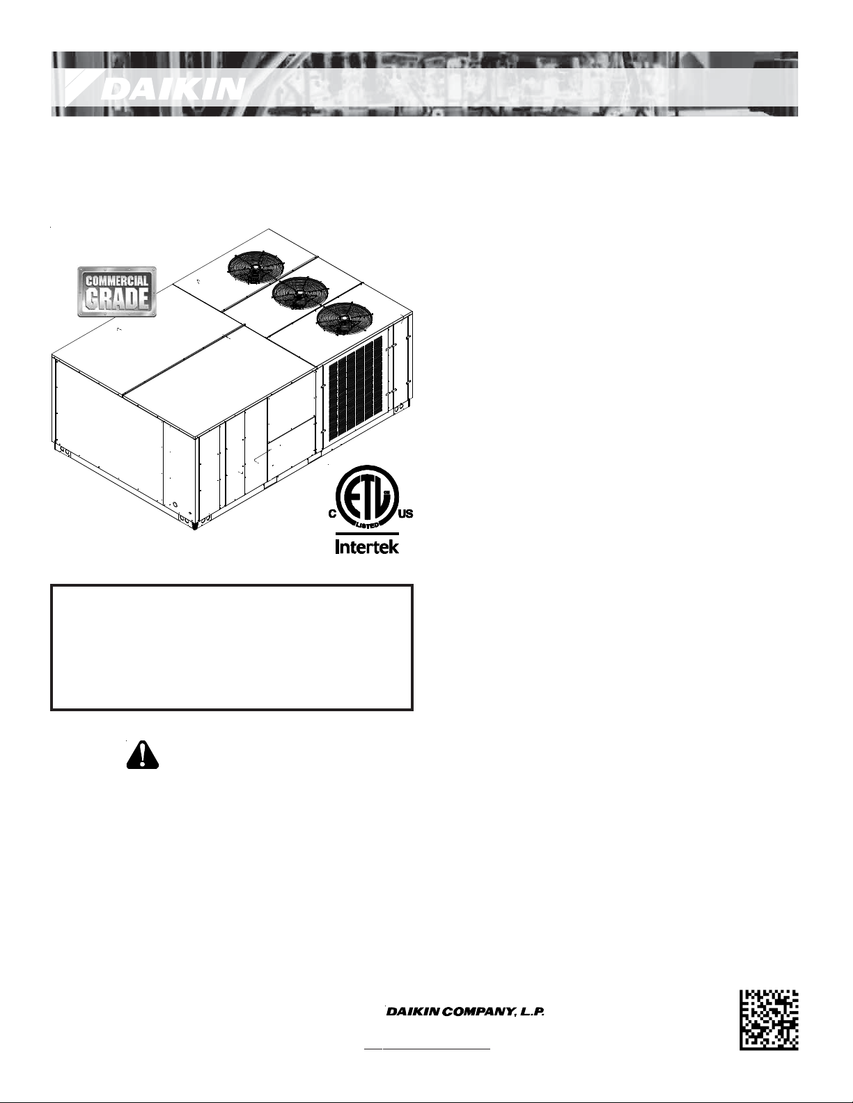
DCC SERIES
LIGHT COMMERCIAL PACKAGED HEATING AND COOLING UNIT
15 to 25 TON
Index
Replacement Parts................................................................ 2
Safety Instructions................................................................2
General Information ............................................................. 2
Unit Location ........................................................................ 3
Clearances ............................................................................ 5
Roof Curb Post-Installation Checks ....................................... 6
Roof Top Duct Connections................................................... 6
Rigging Details ...................................................................... 6
NOTE: 15 & 20 ton model shown in picture.
25 ton model has 2 fans.
ATTENTION INSTALLING PERSONNEL:
Prior to installation, thoroughly familiarize yourself with
this Installation Manual. Observe all safety warnings. During installation or repair, caution is to be observed.
It is your responsibility to install the product safely and to
educate the customer on its safe use.
RECOGNIZE THIS SYMBOL
AS A SAFETY PRECAUTION.
These installation instructions cover the outdoor installation of
single package heating and cooling units. See the Specification
Sheet applicable to your model for information regarding
accessories.
*NOTE: Please contact your distributor or our website for the
applicable Specification Sheet referred to in this manual.
Electrical Wiring.................................................................... 7
Circulating Air and Filters...................................................... 9
Condensate Drain Connection .............................................. 9
Startup, Adjustments, and Checks ...................................... 10
Airflow Adjustments........................................................... 11
Motor Sheave Adjustments ................................................ 12
Maintenance ...................................................................... 13
Appendix A Blower Performance Data................................ 15
Belt Drive - Standard ..................................................... 15
Belt Drive - High Static................................................... 16
Appendix B Electrical Data.................................................. 17
Appendix C Unit Dimensions............................................... 18
Appendix D Wiring Diagrams .............................................. 19
Start-up Checklist................................................................ 2
5
IOD-1003B
5/2015
Our continuing commitment to quality products may mean a change in specifications without notice.
© 2013, 2015
5151 San Felipe St., Suite 500, Houston, TX 77056
www.daikincomfort.com
Page 2
WARNING
T
HIS PRODUCT CONTAINS OR PRODUCES A CHEMICAL OR CHEMICALS
WHICH MAY CAUSE SERIOUS ILLNESS OR DEATH AND WHICH ARE
KNOWN TO THE STATE OF CALIFORNIA TO CAUSE CANCER, BIRTH
DEFECTS OR OTHER REPRODUCTIVE HARM
.
WARNING
HIGH V OLTAG E!
ISCONNECT ALL POWER BEFORE SERVICING OR
D
INSTALLING THIS UNIT
BE PRESENT
DAMAGE, PERSONAL INJURY OR DEATH
. F
. M
AILURE TO DO SO MAY CAUSE PROPERTY
ULTIPLE POWER SOURCES MAY
.
REPLACEMENT PARTS
ORDERING PARTS
When reporting shortages or damages, or ordering repair
parts, give the complete unit model and serial numbers as
stamped on the unit’s nameplate.
Replacement parts for this appliance are available through
your contractor or local distributor. For the location of your
nearest distributor, consult the white business pages, the
yellow page section of the local telephone book or contact:
CONSUMER AFFAIRS
DAIKIN NORTH AMERICA LLC
7401 SECURITY WAY
HOUSTON, TEXAS 77040
855-770-5678
SAFETY INSTRUCTIONS
TO THE INSTALLER
Before installing this unit, please read this manual to
familiarize yourself on the specific items which must be
adhered to, including maximum external static pressure to
unit, air temperature rise, minimum or maximum CFM and
motor speed connections.
Keep this literature in a safe place for future reference.
CAUTION
S
HEET METAL PARTS, SCREWS, CLIPS AND SIMILAR ITEMS INHERENTLY
HAVE SHARP EDGES, AND IT IS NECESSARY THAT THE INSTALLER AND
SERVICE PERSONNEL EXERCISE CAUTION
.
WARNING
T
O PREVENT THE RISK OF PROPERTY DAMAGE, PERSONAL INJURY, OR DEATH,
DO NOT STORE COMBUSTIBLE MATERIALS OR USE GASOLINE OR OTHER
FLAMMABLE LIQUIDS OR VAPORS IN THE VICINITY OF THIS APPLIANCE.
WARNING
HIGH VOLTAGE!
I
NSTALLATION AND REPAIR OF THIS UNIT SHOULD BE
PERFORMED
MINIMUM) THE REQUIREMENTS OF AN
ECHNICIAN” AS SPECIFIED BY THE AIR CONDITIONING
T
EATING, AND REFRIGERATION INSTITUTE
H
TTEMPTING TO INSTALL OR REPAIR THIS UNIT WITHOUT
A
SUCH BACKGROUND MAY RESULT IN PRODUCT DAMAGE
PERSONAL INJURY OR DEATH
ONLY BY
INDIVIDUALS MEETIN G (AT A
“E
NTRY LEVEL
(AHRI).
.
GENERAL INFORMA TION
This unit is approved for outdoor installation ONLY . Rate d perfor mance is achieved after 7 2 hours of operation. Rated performance
is delivered at the specified airflow. See outdoor unit specification sheet for split system models or product specification sheet
for packaged and light commercial models. Specification sheets
can be found at www.daikincomfort.com for Daikin brand products. Within the website, please select the residential or commercial products menu and then select the submenu for the type
of product to be installed, such as air conditioner s or heat pumps,
to access a list of product pages that each contain links to that
model’s specification sheet.
,
,
To assure that your unit operates safely and efficiently, it must be
installed, operated, and maintained in accordance with these installation and operating instructions, all local building codes and
ordinances.
2
Page 3
EPA REGULATIONS
IMPORTANT: THE UNITED STATES ENVIRONMENTAL PROTECTION AGENCY (EPA)
HAS ISSUED VARIOUS REGULATIONS REGARDING THE INTRODUCTION AND DISPOSAL
REFRIGERANTS IN THIS UNIT. FAILURE TO FOLLOW THESE REGULATIONS MAY
OF
THE ENVIRONMENT AND CAN LEAD TO THE IMPOSITION OF SUBSTANTIAL
HARM
. BECAUSE REGULATIONS MAY VARY DUE TO PASSAGE OF NEW LAWS, WE
FINES
A CERTIFIED TECHNICIAN PERFORM ANY WORK DONE ON THIS UNIT.
SUGGEST
SHOULD YOU HAVE ANY QUESTIONS PLEASE CONTACT THE LOCAL OFFICE OF THE
EPA.
d. Copy of the inspection report issued by carrier
representative at the time damage is reported to the
carrier. The carrier is responsible for making prompt
inspection of damage and for a thorough investigation
of each claim. The distributor or manufacturer will not
accept claims from dealers for transportation damage.
NOTE: When inspecting the unit for transportation damage,
remove all packaging ma terials. Recycle or dispose of the packaging
material according to local codes.
NATIONAL CODES
This product is designed and manuf actured to permit installation
in accordance with National Codes. It is the installer’s responsibility to install the product in accordance with National Codes and/
or prevailing local codes and regulations.
The heating and cooling capacities of the unit should be greater
than or equal to the design heating and cooling loads of the area
to be conditioned. The loads should be calculat e d by an approv ed
method or in accordance with ASHRAE Guide or Manual J - Load
Calculations published by the Air Conditioning Contractors of
America.
Obtain from:
American National Standards Institute
1430 Broadway
New York, NY 10018
System design and installation should also, where applicable, follow information pr esente d in accepted industr y guides such as the
ASHRAE Handbooks. The manufacturer assumes no r esponsibility
for equipment installed in violation of any code or regulation. The
mechanical installation of the packaged roof top units consists of
making final connections between the unit and building services;
supply and return duct connections; and drain connections (if required). The internal systems of the unit are completely factoryinstalled and tested prior to shipment.
Units ar e generally installed on a s teel roof mounting curb assembly which has been shipped to the job site for installation on the
roof structure prior to the arrival of the unit. The model number
shown on the unit’s identifica tion plate identifies the v arious components of the unit such as refrigeration tonnage, heating input
and voltage.
Carefully inspect the unit for damage. Any bolts or screws which
may have loosened in transit must be re-tightened. In the event
of damage, the receiver should:
1. Make notation on delivery receipt of any visible damage
to shipment or container.
2. Notify carrier promptly and request an inspection.
3. In case of concealed damage, c arrier should be notified as
soon as possible-preferably within 5 days.
4. File the claim with the following supporting documents:
a. Original Bill of Lading, certified copy, or indemnity bond.
b. Original paid freight bill or indemnity in lieu thereof.
c. Original invoice or certified copy thereof, showing trade
and other discounts or reductions.
PRE-INSTALLATION CHECKS
Carefully read all ins tructions for the installa tion prior t o installing
unit. Ensure each step or procedur e is understood and an y s pecial
considerations are taken into account before starting installation.
Assemble all tools, hardware and supplies needed t o complete the
installation. Some items may need to be purchased locally.
UNIT LOCATION
WARNING
TO
PREVENT POSSIBLE EQUIPMENT DAMAGE, PROPERTY DAMAGE
PERSONAL INJURY OR DEATH, THE FOLLOWING BULLET POINTS MUST
BE OBSERVED WHEN INSTALLING THE UNIT
.
,
IMPORTANT NOTE: Remove wood shipping rails prior to installation of the unit. See important note under Roof Curb Installation
Only.
ALL INSTALLATIONS:
I
MPORTANT NOTE: Unit should be energized 24 hours prior to
compressor start up to ensure crankcase heater has sufficiently warmed the compressors. Compressor damage may
occur if this step is not followed.
NOTE: Appliance is shipped from factory for vertical duct
application.
Proper installation of the unit ensures trouble-free oper ation. Improper installation can result in problems ranging from noisy
operation to property or equipment damages, dangerous conditions that could result in injury or per sonal pr operty damage. Give
this booklet to the user and explain it’ s provisions. The user should
retain these instructions for future reference.
• For proper operation and condensate drainage, the unit
must be mounted level.
• The flue outlet hood must be a t leas t three feet abov e any
forced air inlet located within ten feet. The economizer/
manual fresh air intake/motorized fresh air intake and
combustion air inlet mounted on the unit ar e not aff ected
by this restriction.
• Do not locate the unit in an area where the outdoor air
3
Page 4
(i.e. combustion air for the unit) will be frequently
contaminated by compounds containing chlorine or
fluorine. Common sources of such compounds include
swimming pool chemicals and chlorine bleaches, paint
stripper , adhesiv es, paints, varnishes, sealer s, waxe s (which
are not yet dried) and solvents used during construction
and remodeling. Various commercial and industrial
processes may also be sources of chlorine/fluorine
compounds.
• To avoid possible illness or death of the building occupants,
do NOT locate outside air intake device (economizer,
manual fresh air intake, motorized fresh air intake) too
close to an exhaust outlet, gas vent termination, or
plumbing vent outlet. For specific distances required,
consult local codes.
• Allow minimum clearances from the enclosure for fire
protection, proper oper ation, and service access (see Unit
Clearances). These clearances must be permanently
maintained.
• When the unit is heating, the temperature of the return
air entering the unit must be between 50°F and 100°F.
GROUND LEVEL INSTALLATIONS ONLY:
• When the unit is installed on the ground adjacent to the
building, a level concrete (or equal) base is r ecommended.
Prepare a base that is 3” larger than the package unit
footprint and a minimum of 3” thick.
• The base should also be loc a te d where no runoff of w at er
from higher ground can collect in the unit.
ROOF TOP INSTALLATIONS ONLY:
• To avoid possible property damage or personal injury, the
roof must have sufficient structural strength to carry the
weight of the unit(s) and snow or water loads as required
by local codes. Consult a s tructural engineer to determine
the weight capabilities of the roof.
• The unit may be installed directly on wood floors or on
Class A, Class B, or Class C roof covering material.
• To avoid possible personal injury, a safe, flat surface for
service personnel should be provided.
• As indica ted on the unit’s dat a plate, a minimum cle arance
of 36” to any combustible material is requir ed on the access
side of the unit. All combustible materials must be kept
out of this area.
• This 36” clearance must also be maintained to insure
proper combustion air flow. The combustion air intake
must not be blocked for any re ason, including blockage by
snow.
• Adequate clearances fr om the unit to any adjacent public
walkways, adjacent buildings, building openings or
openable windows must be maintained in accor dance with
National Codes.
• Do not stand or walk on the unit.
• Do not drill holes anywhere in panels or in the ba se frame
of the unit (except where indicated). Unit access panels
provide structural support.
• Do not remove any access panels until unit has been
installed on roof curb or field supplied structure.
• Do not roll unit across finished roof without prior appr oval
of owner or architect.
• Do not skid or slide on any surface as this may damage
unit base. The unit must be stor ed on a flat, level surf ace.
Protect the condenser coil because it is easily damaged.
ROOF CURB INSTALLATIONS ONLY:
Before installing this unit...
IMPORTANT NOTE: This unit has been equipped with a shipping
brace under the compre ssor section that MUST BE REMOVED be-
fore installing the unit on a roof curb.
Please follow the instructions below to remove brace.
CAUTION
W
HEN UNIT IS SUSPENDED, BOARDS AND SHIPPING BRACE WILL DROP WHEN
SCREWS ARE REMOVED
R
EMOVE FORK HOLE BRACKETS, BOARDS AND SHIPPING BRACE FROM BOTTOM
UNIT BEFORE PLACING UNIT ONTO CURB
OF
. TO
PREVENT PERSONAL INJURY
, STAND CLEAR.
.
1. Remove wooden struts and shipping brace per installation
instructions. The struts are located in the fork holes and
are used to protect the unit from damage while lifting with
forks. The shipping brace is located underneath the unit
(under compressors). Also remove the fork hole brackets
as shown in the following figure.
2. Locate and remove the end brackets as shown in the
following graphic.
UNIT PRECAUTIONS
4
Page 5
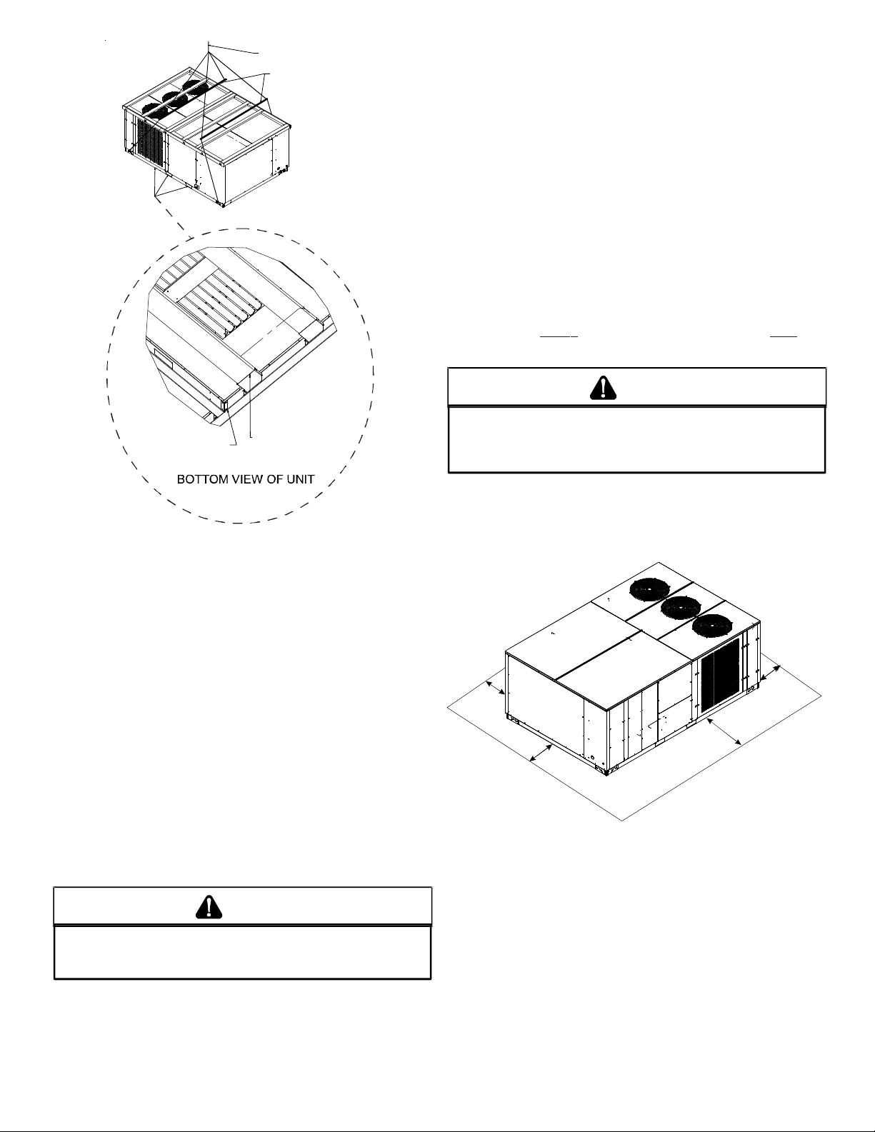
REMOVE 2 BRACKETS
ON EACH END TO
REMOVE
SHI PPING B RACE
LIFT OVER APPROXIMATE
CENTER OF UNIT
SPREADER BARS
MUST BE USED WITH
LIFTING ST RAPS THAT
ARE LESS T HAN 16
FEET LONG
REMOVE 2 BRACKETS
ON EACH END TO
REMOVE
WOODEN STRUTS
• Sufficient structural support must be determined prior to
locating and mounting the curb and package unit.
• Ductwork must be constructed using industry guidelines.
The duct work must be placed into the roof curb before
mounting the package unit. Our full perimeter curbs
include duct connection frames t o be assemble d with the
curb. Cantilevered type curbs are not available from the
factory.
• Curb insulation, cant strips, flashing and general roofing
material are furnished by the contractor.
The curbs must be supported on parallel sides by roof members.
The roof members must not penetrate supply and return duct
opening areas as damage to the unit might occur.
NOTE: The unit and curb accessories are designe d to allo w vertical
duct installation before unit placement. Duct inst allation after unit
placement is not recommended.
CAUTION
ALL
CURBS LOOK SIMILAR
POSITIONING, CHECK JOB PLANS CAREFULLY AND VERIFY MARKINGS
ON CURB ASSEMBLY
SUPERSEDES INFORMATION SHOWN
See the manual shipped with the roof curb for assembly and installation instructions.
. TO
AVOID INCORRECT CURB
. I
NSTRUCTIONS MAY VARY IN CURB STYLES AND
.
3. Lift unit per the “Rigging Details” section of this manual,
observing all warnings and cautions. When unit is lifted,
boards and shipping brace will drop if screws have been
removed. To avoid injury, STAND CLEAR.
4. Dispose of the boards and brace appropriately.
Curb installations must comply with local codes and should be done
in accordance with the e stablished guideline s of the National Roo fing Contractors Association.
Proper unit installation requires that the roof curb be firmly and
permanently attached to the roof structure. Check for adequate
fastening method prior to setting the unit on the curb.
Full perimeter roof curbs are available from the factory and are
shipped unassembled. Field assembly, squaring, leveling and
mounting on the roof structure are the responsibility of the installing contractor. All required hardware necessary for the assembly of the sheet metal curb is included in the curb accessory.
WARNING
TO
PREVENT POSSIBLE EQUIPMENT DAMAGE, PROPERTY DAMAGE
PERSONAL INJURY OR DEATH, THE FOLLOWING BULLET POINTS MUST
BE OBSERVED WHEN INSTALLING THE UNIT
.
,
CLEARANCES
36”; minimum
roof overhang
65”
Min.*
48” Min
.
48”
Min.
*In situations that have multiple units, a 48” minimum clearance is
required between the condenser coils.
UNIT CLEARANCES
Adequate clearance ar ound the unit should be k ept for saf ety , service, maintenance, and proper unit operation. A total clearance
of 75” around this unit is recommended to f acilitate possible blower
assembly , shaft, wheel replacement, coil, heat exchanger, electric
heat and gas furnace removal. This unit must not be installed beneath any obstruction. This unit should be installed remote from
all building exhausts to inhibit ingestion of exhaust air into the
unit’s fresh air intake.
48”
Min.*
5
Page 6
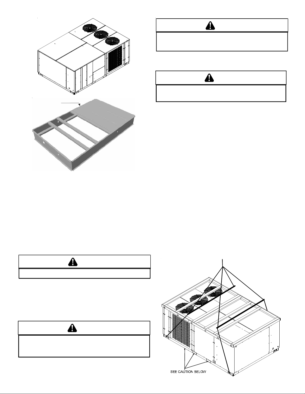
Insulated
Panels
Roof Curb Installation
ROOF CURB POST-INSTALLATION CHECKS
After installa tion, check the top of the curb, duct connection fr ame
and duct flanges to make sure gasket has been applied properly.
Gasket should be firmly applied to the top of the curb perimeter,
duct flanges and any exposed duct connection frame. If gasket is
loose, re-apply using strong weather resistant adhesive.
PROTRUSION
Inspect curb to ensure that none of the utility services (electric)
routed through the curb protrude above the curb.
CAUTION
CAUTION
DO
NOT LIFT UNITS TWO AT A TIME
BEEN INCLUDED IN THE UNIT BASE FRAME
72”
TO PREVENT DAMAGE TO THE UNIT
. P
ROVISIONS FOR FORKS HAVE
. M
INIMUM FORK LENGTH IS
.
Provisions for f orks ha ve been included in the unit base fr ame. No
other fork locations are approved.
WARNING
O PREVENT P OSSIBLE E QUIPMENT DAM AGE, PROPER TY DAMAGE, PERSONAL
T
INJURY OR DEATH, THE FOLLOWING BULLET POINTS MUST BE OBSERVED
WHEN INSTALLING THE UNIT.
• Unit must be lifted by the four lifting holes located at the
base frame corners.
• Lifting cables should be attached t o the unit with shackles.
• The distance between the crane hook and the top of the
unit must not be less than 60”.
• Two spreader bars must span over the unit to prevent
damage to the cabinet by the lift cables. Spreader bars
must be of sufficient length so that cables do not come in
contact with the unit during transport. Remove wood
struts mounted beneath unit base frame before setting
unit on roof curb. These struts are intended to protect
unit base frame from fork lift damage. Removal is
accomplished by extracting the sheet meta l ret ainer s and
pulling the struts through the base of the unit. Refer to
rigging label on the unit.
Important: If using bottom discharge with roof curb, ductwork
should be attached to the curb prior t o installing the unit. Ductwork
dimensions are shown in Roof Curb Installation Instructions.
Refer to the Roof Curb Installation Instructions for proper curb
installation. Curbing must be installed in compliance with the National Roofing Contractors Association Manual.
Lower unit carefully onto roof mounting curb. While rigging unit,
center of gravity will cause condenser end to be lower than supply
air end.
IF
PROTRUSIONS EXIST, DO NO ATTEMPT TO SET UNIT ON CURB
.
ROOF TOP DUCT CONNECTIONS
Install all duct connections on the unit before placing the unit on
rooftop.
RIGGING DET AILS
WARNING
O PREVENT PROPERTY DAMAGE, THE UNIT SHOULD REMAIN IN AN UPRIGHT
T
POSITION DURING ALL RIGGING AND MOVING OPERATIONS.
LIFTING AND MOVING WHEN A CRANE IS USED, PLACE THE UNIT IN AN
ADEQUATE CABLE SLING.
O FACILITATE
T
6
Page 7
CAUTION
A
W
HEN UNIT IS SUSPENDED, BOARDS AND SHIPPING BRACE WILL DROP WHEN
SCREWS ARE REMOVED
R
EMOVE FORK HOLE BRACKETS, BOARDS AND SHIPPING BRACE FROM BOTTOM
UNIT BEFORE PLACING UNIT ONTO CURB
OF
. TO
PREVENT PERSONAL INJURY
, STAND CLEAR.
.
RIGGING REMOVAL
TO
PREVENT DAMAGE TO THE UNIT, DO NOT ALLOW CRANE HOOKS
AND SPREADER BARS TO REST ON THE ROOF OF THE UNIT
CAUTION
.
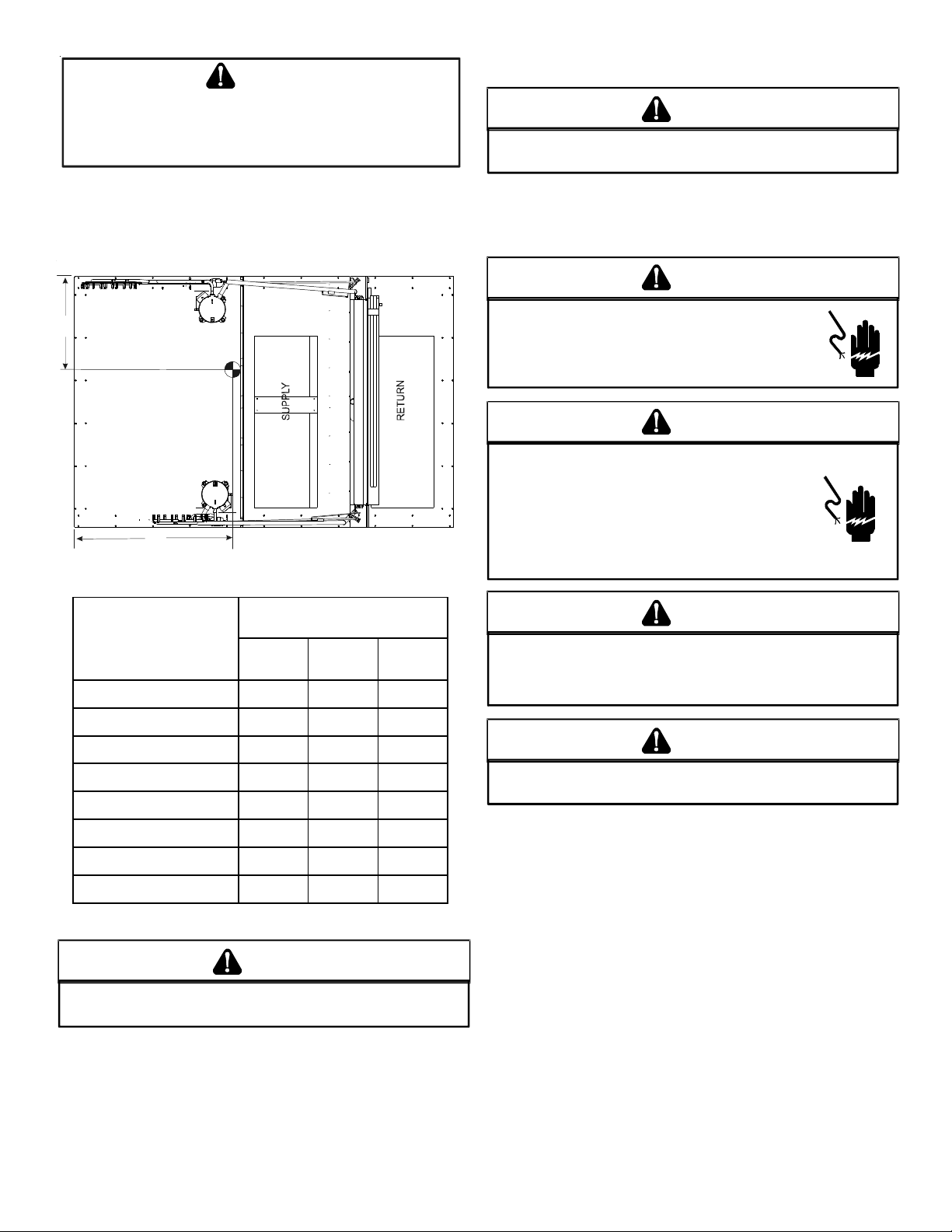
To assist in determining rigging requirements, unit weights are
shown as follows:
Y
COMPRESSOR 1
S
L
I
O
C
R
O
T
A
R
O
P
A
V
E
B
CG
COMPRESSOR 2
X
CORNER & CENTER OF GRAVITY LOCATIONS
DCC W eights
DATA
(lbs)
15 Tons 20 Tons 25 Tons
Corner Weight - A 590 644 626
Corner Weight - B 482 525 464
Corner Weight - C 492 504 501
Corner Weight - D 401 412 518
Un it Ship p in g Wei g ht 2080 2202 2377
Un it Opera ting Wei g ht 1965 2085 2109
X (Inches) 60" 58" 64.3"
Y (Inches) 40" 40" 41.3"
NOTE: These weights are without accessories installed.
CAUTION
TO
PREVENT SEVERE DAMAGE TO THE BOTTOM OF THE UNIT, DO NOT
FORK LIFT UNIT AFTER WOOD STRUTS HAVE BEEN REMOVED
.
Bring condenser end of unit into alignment with the curb. With
condenser end of the unit resting on curb member and using curb
as a fulcrum, lower opposite end of the unit until entire unit is
seated on the curb. When a rectangular cantilever curb is used,
care should be taken to center the unit. Check for proper alignment and orientation of supply and return openings with duct.
Remove spreader bar s, lifting cables and other rigging equipment.
ELECTRICAL WIRING
C
HIGH VOLTAGE!
D
ISCONNECT ALL POWER BEFORE SERVICING OR
INSTALLING THIS UNIT
BE PRESENT
DAMAGE, PERSONAL INJURY OR DEATH
. F
HIGH VOLTAGE!
O AVOID PERSONAL INJURY OR DEATH DUE TO
T
ELECTRICAL SHOCK, DO NOT TAMPER WITH FACTORY
WIRING
. THE
OF THESE UNITS ARE FACTORY-INSTALLED AND HAVE
BEEN THOROUGHLY TESTED PRIOR TO SHIPMENT
D
C
ONTACT YOUR LOCAL REPRESENTATIVE IF
ASSISTANCE IS REQUIRED
INTERNAL POWER AND CONTROL WIRING
. M
AILURE TO DO SO MAY CAUSE PROPERTY
WARNING
ULTIPLE POWER SOURCES MAY
.
WARNING
.
.
CAUTION
TO
PREVENT DAMAGE TO THE WIRING, PROTECT WIRING FROM
SHARP EDGES
LOCAL CODES AND ORDINANCES
REMOVABLE ACCESS PANELS
. F
OLLOW NATIONAL ELECTRICAL CODE AND ALL
. DO
NOT ROUTE WIRES THROUGH
.
CAUTION
C
ONDUIT AND FITTINGS MUST BE WEATHER-TIGHT TO PREVENT
WATER ENTRY INTO THE BUILDING
.
For unit protection, use a fuse or HACR circuit breaker that is in
excess of the circuit ampacity, but less than or equal to the maximum overcurrent protection device. DO NOT EXCEED THE MAXIMUM OVERCURRENT DEVICE SIZE SHOWN ON UNIT DATA PLATE.
All line voltage connections must be made through weatherproof
fittings. All exterior power supply and ground wiring must be in
approved weatherproof conduit.
The main power supply wiring to the unit and low voltage wiring
to accessory controls must be done in accordance with these instructions, the latest edition of the Na tional Electrical Code (ANSI/
NFPA 70), and all local codes and ordinances. All field wiring shall
conform with the temperature limitations for Type T wire (63°F/
35°C rise).
The main power supply shall be three-phase, three wir e. The unit
is factory wired for the voltage shown on the unit’s data plate.
7
Page 8
NOTE: If supply voltage is 208V , all le ads on primary of tr ansformer
e
t
TRANS1 must be moved from the 230V to the 208V tap.
Main power wiring should be sized for the minimum wir e ampacity
shown on the unit’s data plate. Size wires in accordance with the
ampacity tables in Article 310 of the National Electrical Code. If
long wires are required, it may be necessary to increase the wire
size to prevent ex cessive vol tage drop. Wires should be sized for a
maximum of 3% voltage drop.
CAUTION
O AVOID PROPERTY DAMAGE OR PERSONAL INJURY DUE TO FIRE, USE
T
ONLY COPPER CONDUCTORS.
CAUTION
L
ABEL ALL WIRES PRIOR TO DISCONNECTION WHEN SERVICING
CONTROLS
DANGEROUS OPERATION
SERVICING
. W
IRING ERRORS CAN CAUSE IMPROPER AND
. V
ERIFY PROPER OPERATION AFTER
.
NOTE: A weather-tight disconnect switch, properly sized for the
unit total load, must be field or f actory installed. An e xternal field
supplied disconnect may be mounted on the exterior panel.
Ensure the data plate is not covered by the field-supplied
disconnect switch.
• Some disconnect switches are not fused. Protect the
power leads at the poin t of distribution in accordance with
the unit’s data plate.
• The unit must be electrically grounded in acc ordance with
local codes or, in the absence of local codes, with the late st
edition of the National Electrical Code (ANSI-NFPA 70). A
ground lug is provided for this purpose. Size grounding
conductor in accordance with T able 2 50-95 of the National
Electrical Code. Do not use the ground lug for connecting
a neutral conductor.
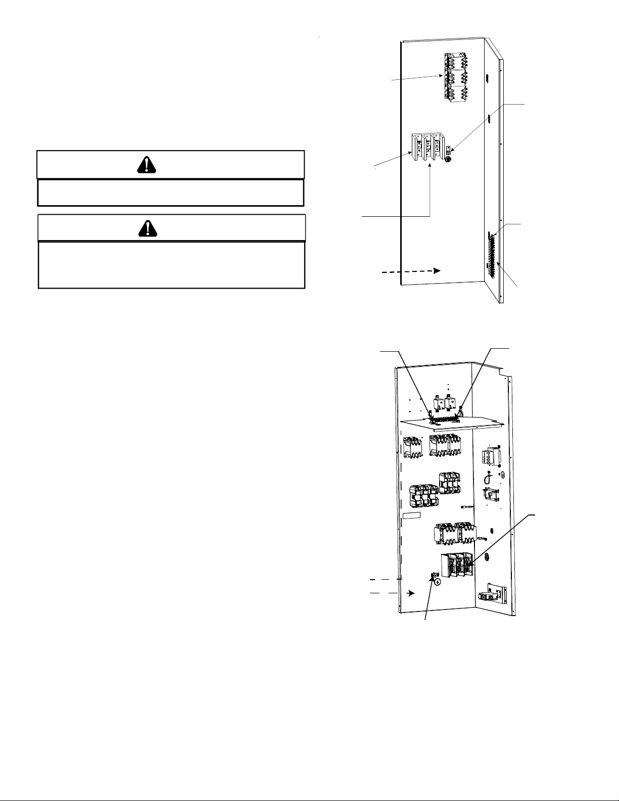
• Connect power wiring to the electrical middle contactor
within the main control box of power block, if equipped.
Line voltage connects
to middle contactor
on 460v and 575v
Gas Packs
(or power bloc k
if equipped)
Power Block
(Coolers &
230V Gas Packs
Only)
Line voltage connects
to power blo ck on
Coolers and the 230v
Gas Packs
Field wirin g enters
from this direction
POWER AND LOW VOLTAGE BLOCK LOCATIONS
Route field
control wiring
through
grommet
Ground
Lug
Low Voltage
Terminal Strip
Thermostat wiring
for all unit s
connect to low
voltage stri p
Fieldconnection
for
control wiring
at
terminal block
Field
connection
for
linevoltage
Field wiring
LOW
nters from
his direction
HIGH
Ground Lug
25 TON POWER AND LOW VOLTAGE BLOCK LOCATIONS
8
Page 9
WARNING
A
F
AILURE OF UNIT DUE TO OPERATION ON IMPROPER LINE VOLTAGE
OR WITH EXCESSIVE PHASE UNBALANCE CONSTITUTES PRODUCT
ABUSE AND MAY CAUSE SEVERE DAMAGE TO THE UNIT ELECTRICAL
COMPONENTS
.
Areas Without Convenience Outlet
It is recommended that an independent 115V power source be
brought to the vicinity of the roof top unit for portable lights and
tools used by the service mechanic.
3. Use #18 AWG wire for 24V control wiring runs not
exceeding 75 fee t. Use #16 A WG wire f or 24V control wiring
runs not exceeding 125 feet. Use #14 AWG wire for 24V
control wiring runs not exceeding 200 feet. Low voltage
wiring may be National Electrical Code (NE C) Class 2 where
permitted by local codes.
4. Route thermostat wires from sub-base terminals to the
unit. Control wiring should enter through the duct panel
(dimple marks entrance location). Connect thermost at and
any accessory wiring to low voltage terminal block TB1 in
the main control box.
NOTE: Refer to local codes for requirements. These outlets can
also be factory installed.
UNITS INSTALLED ON ROOF TOPS
Main power and low voltage wiring may enter the unit through
the side or through the roof curb. Ins tall conduit connectors at the
desired entrance locations. External connectors must be weatherproof . All hole s in the unit base mus t be sealed (including those
around conduit nuts) to prevent water leakage into building. All
required conduit and fittings are to be field supplied.
Supply voltage to roof top unit must not vary by mor e than 10% of
the value indicated on the unit’s data plate. Phase voltage unbalance must not exceed 2%. Contact your local power comp any for
correction of improper voltage or phase unbalance.
NOTE: Field-supplied conduit may need t o be installed depending
on unit/curb configuration. Use #18 AWG solid conductor wire
whenever connecting thermostat wir es to terminals on sub-ba s e.
DO NOT use larger than #18 AWG wire. A transition to #18 AWG
wire may be required before entering thermostat sub-base.
NOTE: Refer to unit wiring diagrams for thermostat hookups.
CIRCULA TING AIR AND FILTERS
DUCTWORK
The supply duct from the unit through a wall may be ins talled without clearance. However, minimum unit clearances must be maintained (see “Clearances” section). The supply duct should be pr ovided with an access panel large enough to inspect the air chamber downstream of the heat exchanger. A cover should be tightly
attached to prevent air leaks.
Ductwork dimensions are shown in the roof curb installation
manual.
If desired, supply and return duct connections to the unit may be
made with flexible connections to reduce possible unit operating
sound transmission.
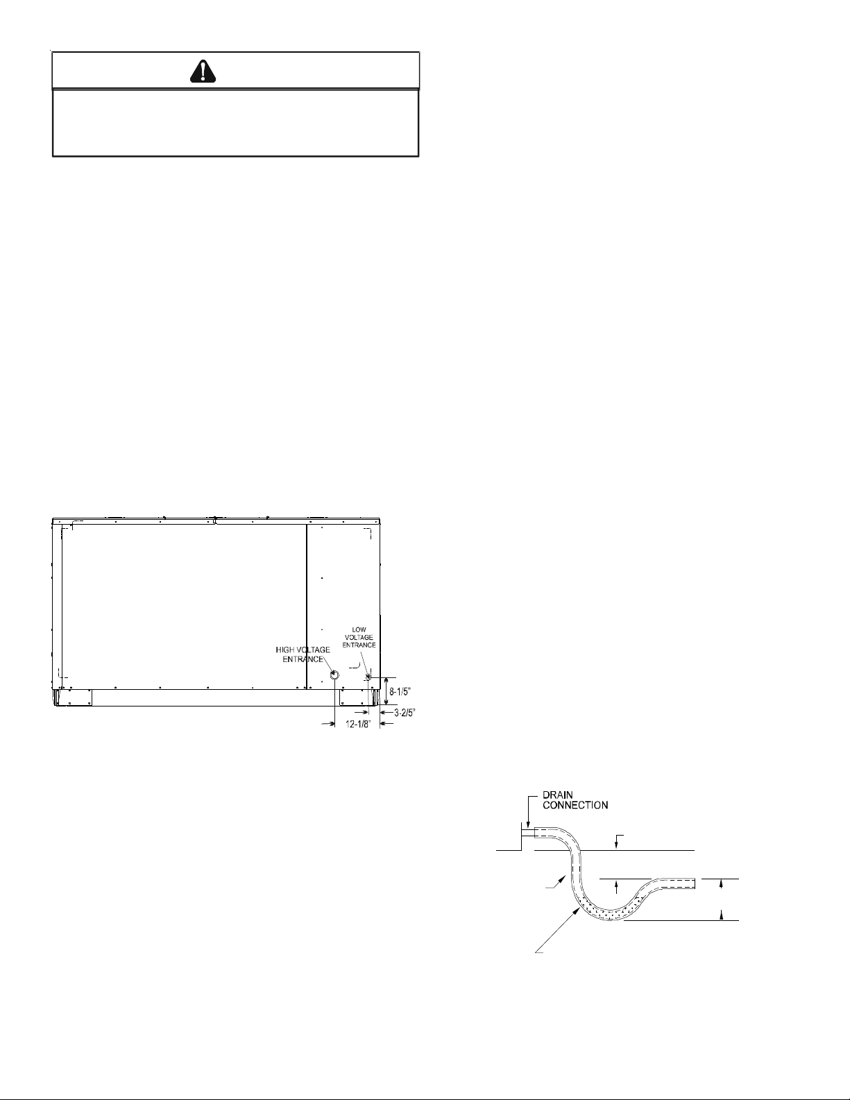
ELECTRICAL ENTRANCE LOCATIONS
Unit is equipped with Single Point Power Block and Low Voltage
Block.
LOW VOLTAGE CONTROL WIRING
1. A 24V thermostat must be installed for unit operation. It
may be purchased with the unit or field -supplied.
Thermostats may be pr ogrammable or electr omechanic al
as required.
2. Locate thermostat or remote sensor in the conditioned
space where it will sense average temperature. Do not
locate the device where it may be directly exposed to
supply air, sunlight or other sources of heat. Follow
installation instructions packaged with the thermostat.
CONDENSATE DRAIN CONNECTION
CONDENSATE DRAIN CONNECTION
A 1” female NPT drain connection is supplied on the side of the
unit and a 1” male NPT on the bottom of the drain pan for condensate piping. An external tr ap must be ins talled f or proper c ondensate drainage.
UNIT 2" MINIMUM
FLEXIBLE
TUBING-HOSE
OR PIPE
POSITIVE LIQUID
SEAL IS REQUIRED
DRAIN CONNECTION
Install condensate drain trap as shown. Use 1" drain line and fit-
9
3" MINIMU M
Page 10

tings or larger. Do not operate without trap.
HORIZONTAL DRAIN
Drainage of condensate dir ectly on to the roof may be acceptable;
refer to local code. It is recommended that a small drip pad of
either stone, mortar, wood or metal be provided to prevent any
possible damage to the roof.
CLEANING
Due to the fact that drain pans in any air conditioning unit
will have some moisture in them, algae and fungus will grow
due to airborne bacteria and spores. Periodic cleaning is
necessary to prevent this build-up from plugging the drain.
ST ARTUP, ADJUSTMENTS, AND CHE CK S
by-step sequence which, if f ollowed, will assur e the proper startup
of the equipment in the minimum amount of time. Air balancing
of duct system is not considered part of this procedure. However,
it is an important phase of any air conditioning sy stem startup and
should be performed upon completion of the Startup, Adjustmen ts,
and Checks procedure. The Startup, Adjustmen ts, and Checks procedure at outside ambient s below 55°F should be limited to a re adiness check of the refrigeration s ystem with the r equired final check
and calibration left to be completed when the outside ambient
rises above 55°F.
TEMPORARY HEATING OR COOLING
If the unit is to be used for t emporary heating or cooling, a “Startup,
Adjustments, and Checks” must first be performed in accordance
with this manual. After the machines are used for t emporary heat ing or cooling, inspect the coils, fans, and motors for unacceptable levels of construction dust and dirt and install new filters.
WARNING
HIGH VOLTAGE!
O AVOID PERSONAL INJURY OR DEATH DUE TO
T
ELECTRICAL SHOCK, B
THE BUILDING ELECTRICAL GROUND BY USE OF THE
GROUNDING TERMINAL PROVIDED OR OTHER
ACCEPTABLE MEANS
SERVICING OR INSTALLING THIS UNIT
OND THE FRAME OF THIS UNIT TO
. D
ISCONNECT ALL POWER BEFORE
.
PRE-STARTUP INSTRUCTIONS
CAUTION
TO
PREVENT PROPERTY DAMAGE OR PERSONAL INJURY
START THE UNIT UNTIL ALL NECESSARY PRE-CHECKS AND TESTS
HAVE BEEN PERFORMED
.
, DO
NOT
Prior to the beginning of Startup, Adjustments, and Checks procedures, the following steps should be completed in the building.
WARNING
MOVING MACHINERY HAZARD!
O PREVENT POSSIBLE PERSONAL INJURY OR DEATH, DISCONNECT
T
POWER TO THE UNIT AND PADLOCK IN THE
SERVICNG FANS
.
“OFF”
POSITION BEFORE
HEATING STARTUP
On new installations, or if a major component has been replaced,
the operation of the unit must be checked.
Check unit operation as outlined in the following instructions. If
any sparking, odors, or unusual sounds are encountered, shut off
electrical power and recheck for wiring errors, or obstructions in
or near the blower motors. Duct covers must be removed bef o re
operating unit.
The Startup, Adjustments, and Checks procedure provides a step-
CONTRACTOR RESPONSIBILITY
The installing contractor must be certain that:
• All supply and return air ductwork is in place, properly
sealed and corresponds with installation instructions.
• All thermostats are mounted and wired in accordance
with installation instructions.
• All electric power, all gas, hot water or steam line
connections, and the condensate drain installation have
been made to each unit on the job. These main supply
lines must be functional and cap able of operating all units
simultaneously.
• All filters are in place.
ROOF CURB INSTALLATION CHECK
Inspect the roof curb for correct installation. The unit and curb
assembly should be level. Inspect the flashing of the roof mounting curb to the roof, especially at the corners, for good workmanship. Also check for leaks ar ound gaskets. Note any deficiencies in
a separate report and forward to the contractor.
OBSTRUCTIONS, FAN CLEARANCE AND WIRING
Remove any extraneous construction and shipping materials that
may be found during this procedure. Rotate all fans manually to
check for proper clearances and that they rotate freely. Check for
bolts and screws that may have jarred loose during shipment to
the job site. Retighten if necessary. Re-tighten all electrical connections.
FIELD DUCT CONNECTIONS
Verify that all duct connections are tight and that there is no air
bypass between supply and return.
FILTER SECTION CHECK
Remove filter section access panels and check tha t filters are properly installed. Note airflow arrows on filter frames.
PRE-STARTUP PRECAUTIONS
10
Page 11

It is important to your safety that the unit has been properly
grounded during installa tion. Check ground lug connection in main
control box for tightness prior to closing circuit break er or disconnect switch. Verify that supply voltage on line side of disconnect
agrees with voltage on unit identification plate and is within the
utilization voltage range as indicate d in Appendix C Electrical Data.
System Voltage - That nominal voltage value assigned to a circuit
or system for the purpose of designating its voltage class.
Nameplate Voltage - That voltage assigned to a piece of equipment for the purpose of designating its voltage class and for the
purpose of defining the minimum and maximum voltag e a t which
the equipment will operate.
Utilization Voltage - The vo ltage of the line terminals of the equipment at which the equipment must give fully satisfactory performance. Once it is established that supply voltage will be maintained within the utilization range under all system conditions,
check and calculate if an unbalanced condition exists between
phases. Calculate percent voltage unbalance as follows:
Three Phase Models Only
2) MAXIMUM VOLTAGE DEVIATIONS
3) PERCENT VOLTAGE
UNBALANCE
HOW TO USE THE FORMULA:
EXAMPLE: With voltage of 220, 216, and 213
1) Average Voltage = 220+216+213=649 / 3 = 216
2) Maximum Voltage Deviations from Average Voltage = 220 - 216 = 4
3) Percent Voltage Unbalance = 100 x = = 1.8%
Percent voltage unbalance MUST NOT exceed 2%
= 100 X
FROM AVERAGE VOLTAG E
1) AVERAGE VOLTAGE
4
216
400
216
.
AIRFLOW ADJUSTMENTS
the economizer at full outside air and at minimum out side air . Upon
completion of the air flow balancing, we recommend replacing
the variable pitched motor sheave with a properly-sized fixed
sheave. A ma tching fixe d she ave will pro vide longer belt and be ar ing life and vibration free operation. Initially, it is best to have a
variable pitched motor sheave for the purpose of airflow balancing, but once the balance has been achieved, fixed sheaves maintain alignment and minimize vibration more effectively. For direct
drive units, move green wire for fan.
NOTE: On “non-two speed models” (two-spee d models have a “V”
in the eleventh character of the model number), never run CFM
below 300 CFM per ton. Evaporator freezing or poor unit performance is possible.
SET EVAPORATOR FAN RPM
Actual RPM’ s must be set and verified with a tachome ter or strobe
light. Refer to Appendices A and B for basic unit fan RPM. Refer
also to “Airflow ” section of this manual. With disconnect switch
open, disconnect thermostat wires from terminals Y and W. This
will prevent heating and mechanical c ooling from coming on. Place
a jumper wire across terminals R and G a t TB1 terminal block. Close
disconnect switch; evaporator fan motor will operate so RPM can
be checked.
EVAPORATOR FAN ROTATION CHECK (THREE PHASE MODELS ONLY)
Check that fan rotat es clockwise when vie wed from the drive side
of unit and in accordance with rotation arrow shown on blower
housing. If it does not, reverse the two incoming power cables at
Single Point Power Block. In this case, repeat bearing check.
Do not attempt to change loa d side wiring. In ternal wiring a ssur es
all motors and compressors will rotate in correct direction once
evaporator fan motor rotation check has been made.
NOTE: F or 2 Spee d Models, airflow adjus tments mus t be ma de on
high speed, i.e., 2nd stage cooling or in heat mode.
The drive on the supply fan is typically set in the middle of the
RPM range. The drive motor sheave pitch diameter is field adjustable for the required airflow. Refer to the following “Drive
Adjustments” section.
When the final adjustments are complete, the curren t draw of the
motor should be checked and compared to the full load current
rating of the motor. The amperage must not exceed the service
factor stamped on the motor nameplate. The total airflow must
not be less than that required f or oper a tion of the electric hea ters
or the furnace.
If an economizer is installe d, check the unit operating balance with
ELECTRICAL INPUT CHECK
Make preliminary check of evapor ator fan amper e draw and verify
that motor nameplate amps are not exceeded. A final check of
amp draw should be made upon completion of air balancing of
the duct system (see Appendix C).
BELT DRIVE MODELS ONLY
BEARING CHECK
Prior to energizing any fans, check and mak e sure that all set screws
are tight so that bearings are properly secured to shafts.
TENSION AND ALIGNMENT ADJUSTMENT
Correct belt tension is very important to the life of your belt. Too
loose a belt will shorten its life; too tight, premature motor and
bearing failure will occur. Check you belt drive f or adequate “runin” belt tension by measuring the force required to deflect the
belt at the midpoint of the span length. Belt tension force can be
measured using a belt tension gauge, available through most belt
drive manufacturers.
11
Page 12

S
P
A
N
L
E
N
G
T
H
*
D
E
F
t
F
E
L
C
T
I
O
N
O
R
C
E
NOTE: Future adjustments should be made by loosening the belt
tension and increasing or decreasing the pitch diameter of the
sheave by half or full turns as require d. Readjust belt tension bef ore
starting drive.
D
h
H
d
C
*Apply force to the center of the span.
t = Span length, inches
C = Center distance, inches
D = Larger sheave diameter, inches
d = Smaller sheave diameter, inches
h = Deflection height, inches
DRIVE BELT TENSION ADJUSTMENT
MODEL
15 Ton B, BX Standard 4.3 to 5.5 5.5 ± .5 8.2 ± .5 1/4 ± 1/16
20 T on
25 T on
TYPE
BELT DRIVE Used New
B, BA Standard 4.3 to 5.5 5.5 ± .5 8.2 ± .5 1/4 ± 1/16
SHEA VE
DIAMETER
(in)
DEFLEC TION
FORCE (lbs)
DEFLECTION
(in)
RECOMMENDED POUNDS OF FORCE PER BELT
New V-belts will drop rapidly during the first few hours of use.
Check tension frequently during the first 24 hours of operation.
T ension should fall be tw een the minimum and maximum fo rce. To
determine the deflection distance from a normal position, measure the distance from sheave to sheave using a straightedge or a
cord. This is your reference line. On multiple belt drives, an adjacent undeflected belt can be used as a reference.
MOTOR SHEAVE ADJUSTMENTS
VL, VM & 2VP VARIABLE PITCH KEY TYPE MOTOR SHEAVES
The driving and driven motor sheaves should be in alignment with
each other and the shafts parallel.
VL & VM SHEAVES ADJUSTMENT
1. Loosen set screw “B” using a 5/32" Allen key.
2. Making half or full turns from closed position, adjust
sheave pitch diameter for desired speed. DO NOT OPEN
MORE THAN SIX FULL TURNS.
3. Tighten set screw “B” securely over flat.
4. Carefully put on belts and adjust belt tension. DO NOT
FORCE BELTS OVER GROOVES.
5. Ensure all keys are in place and the set screws tight bef ore
starting drive. Recheck set screws and belt tension after
24 hours service.
C
B
VL & VM
NOTE: Do not operate sheave with flange projecting beyond the
hub end.
REFRIGERATION SYSTEM
The unit is equipped with a thermal expansion valve as a
metering device.
Ensure the hold-down bolts on the compressor ar e secure and have
not vibrated loose during shipment. Check that vibration grommets have been installed. Visually check all piping for damage and
leaks; repair if necessary. The entire system has been factory
charged and test ed, making it unnecessary t o field charge. F actory
charges are sho wn on the unit’ s namelate. To confirm charge levels or , if a leak occurs and charg e needs to be a dded to the sy st em,
it is recommended to evacuate the system and recharge refrigerant to unit nameplate specifications. This unit has been rated in
the cooling mode at the AHRI rat ed conditions of: Indoor (80°db /
67°wb) and outdoor (95°db). While operating at this condition,
the subcooling should range from 12° to 15° F for each refrigeration circuit, for 15 and 20 ton models. Subcooling for 25 ton models should be from 16° to 19° F for circuit 1, and from 12° to 15° F
for circuit 2.
START-UP PROCEDURE AND CHECKLIST
Begin with power turned off at all disconnects.
1. Turn thermostat system switch to “Cool,” and fan switch
to “Auto” and turn temperature setting as high as it will
go.
2. Inspect all registers and set them to the normal open
position.
3. Turn on the electrical supply at the disconnect.
4. Turn the fan switch to the “ON” position. The blower
12
Page 13

should operate after a 7-second delay.
5. T urn the f an switch to “Auto” position. The blower should
stop after a 65 second delay.
6. Slowly lower the cooling temperature un til first stage COOL
(LOW COOL) starts. The blower, both fans, and first stage
compressor should now be operating. Allow the unit to
run 10 minutes, make sure cool air is being supplied by
the unit.
WARNING
HIGH VOLTAGE!
ISCONNECT ALL POWER BEFORE SERVICING OR
D
INSTALLING THIS UNIT
BE PRESENT
DAMAGE, PERSONAL INJURY OR DEATH
. F
. M
AILURE TO DO SO MAY CAUSE PROPERTY
ULTIPLE POWER SOURCES MAY
.
7. Lower the cooling temperature further un til second stag e
COOL (HIGH COOL) starts. The blower, both fans, and
both
compressors should now be operating. Allow the unit to
run 10 minutes, make sure cool air is being supplied by
the unit.
8. Turn the temperature setting to the highest position,
stopping the unit. The indoor blower will continue to run
for 65 seconds.
9. Turn the thermostat system switch to “OFF” and
disconnect all power when servicing the unit.
START-UP PROCEDURE AND CHECKLIST FOR 2 SPEED MODELS:
Models with a V in the 11th position of the model number.
For 2 speed models, the indoor blower will operate on low speed
when in “Fan Only” mode or while in first stage “Cooling” mode.
Unit will operate on high speed in “Heating” mode and while in
second stage “Cooling” mode.
The start-up procedure is the same as for “Air Conditioning Startup Procedure” with the understanding that in Step 6, the indoor
blower will run at low speed (~1175 motor rpm) and in Step 7, the
indoor blower will operate at high speed (~1775 motor rpm).
NOTE: While in the Cooling Mode, to prevent frost from forming
on the evaporator while the unit is operating in outdoor
temperatures of 65°F or lower, it is recommended that a low
ambient kit (LAKT -**) is use d. This is strongly recommended for 2
Speed models due to the lower airflow while in the first stage
cooling. To further protect the compressor from damage during
low ambient conditions, a Freeze stat K it (FSK01) can be added tha t
turns the compressor off when the ev apora tor temperature dr ops
too low.
FINAL SYSTEM CHECKS
10. Check to see if all supply and return air grilles are adjuste d
and the air distribution system is balanced for the best
compromise between heating and cooling.
11. Check for air leaks in the ductwork. See Sections on Air
Flow Adjustments.
12. Make sure the unit is free of “rattles”, and the tubing in
the unit is free from excessive vibration. Also make sure
tubes or lines are not rubbing against each other or sheet
metal surfaces or edges. If so, correct the trouble.
13. Set the thermostat at the appropriate setting for cooling
and heating or automatic change over for normal use.
14. Be sure the Owner is instructed on the unit operation, filter ,
servicing, correct thermostat operation, etc.
MAINTENANCE
WARNING
HIGH VOLTAGE!
D
ISCONNECT ALL POWER BEFORE SERVICING OR
INSTALLING THIS UNIT
BE PRESENT
DAMAGE, PERSONAL INJURY OR DEATH
. F
. M
AILURE TO DO SO MAY CAUSE PROPERTY
ULTIPLE POWER SOURCES MAY
.
WARNING
TO
PREVENT PERSONAL INJURY OR DEATH DUE TO IMPROPER
INSTALLATION, ADJUSTMENT, ALTERATION, SERVICE OR
MAINTENANCE, REFER TO THIS MANUAL
ASSISTANCE OR INFORMATION, CONSULT A QUALIFIED INSTALLER
SERVICE AGENCY OR THE GAS SUPPLIER
. FOR
.
ADDITIONAL
,
13
Page 14

CAUTION
Dirty throwaway filters should be discarded and replaced with a
new, clean filter.
S
HEET METAL PARTS, SCREWS, CLIPS AND SIMILAR ITEMS INHERENTLY
HAVE SHARP EDGES, AND IT IS NECESSARY THAT THE INSTALLER AND
SERVICE PERSONNEL EXERCISE CAUTION
.
Preventive maintenance is the best way to avoid unnecessary expense and inconvenience. Have this system inspected at regular
intervals by qualified service personnel, a t leas t twice a ye ar. Routine maintenance should cover the following items:
1. Tighten all belts, set screws, and wire connections.
2. Clean evapora tor and condenser coils mechanically or with
cold water, if necessary. U sually any f ouling is only mat ted
on the entering air face of the coil and can be remov e d by
brushing.
3. Lubricate motor bearings.
4. Align or replace belts as needed.
5. Replace filters as needed (see below).
6. Check for blockage of condensate drain.
7. Check power and control voltages.
8. Check running amperage.
9. Check operating temperatures and pressures.
10. Check and adjust temperature and pressure controls.
11. Check and adjust damper linkages.
12. Check operation of all safety controls.
13. Examine gas furnaces (see below and the User’s
Information Manual).
14. Check condenser fans and tighten set screws.
Disposable return air filters are supplied with this unit. See the
unit Specification Sheet or Technical Manual for the correct size
and part number. To remove the filters, remove the filter access
panel on return side of the unit.
CABINET FINISH MAINTENANCE
Use a fine gra de automotive w ax on the cabinet finish t o maintain
the finish’s original high luster. This is especially important in installations with extended periods of direct sunlight.
CLEAN OUTSIDE COIL (QUALIFIED SERVICER ONLY)
The coil with the outside air flowing over it should be inspected
annually and cleaned as frequen tly as necessary to keep the finned
areas free of lint, hair and debris.
CONDENSER FANS
Bearings on the condenser fan motors are permanen tly lubricated .
No additional oiling is required.
LUBRICATION
The fan shaft bearings and the supply fan motor have grease fittings that should be lubricated during normal maint enance checks.
FUNCTIONAL PARTS
Refer to the unit Parts Catalog for a list of functional parts. Parts
are available from your distributor.
FILTERS
CAUTION
T
O PREVENT PRO PERTY DAMAG E DUE TO FIRE AND LOSS O F
EQUIPMENT EFFICIENCY OR EQUIPMEN T DAMAGE DUE TO DUST AND LINT
BUILD UP ON INTERNAL PARTS, NEVER OPERATE UNIT WITHOUT AN AIR
FILTER INSTALLED IN THE RETURN AIR SYSTEM.
Every application may require a different frequency of replacement of dirty filters. Filters must be replaced at least every three
(3) months during operating seasons.
Dirty filters are the most common cause of inadequate heating or
cooling performance. Filter inspection should be made at least
every two months; more often if nece ssary because of local conditions and usage.
14
Page 15

APPENDIX A BLOWER PERFORMANCE DATA
BELT DRIVE - STANDARD
DCC180 STANDARD BELT DRIVE (includes 2 speed models at hi gh speed)
TURNS OPEN
ESP, In H2O
0.2
0.4
0.6
0.8
1.0
1.2 4426 1.71 --- --- --- --- --- --- --- --- --- --- --- ---
DCC240 STANDARD BELT DRIVE (includes 2 speed models at high speed)
ESP, In H2O
0.2
0.4
0.6
0.8
1.0
1.2 7344 4.35
0123456
CFM BHP CFM BHP CFM BHP CFM BHP CFM BHP CFM BHP CFM BHP
--- --- --- --- --- --- --- --- --- --- 7203 2.18 6718 1.94
--- --- --- --- --- --- 7306 2.54 6777 2.14 6257 1.80 5711 1.66
--- --- 7477 2.97 6899 2.51 6323 2.10 5716 1.72 5103 1.39 --7112 2.96 6467 2.46 5795 2.01 5101 1.61 --- --- --- --- --- --5983 2.38 5190 1.89 --- --- --- --- --- --- --- --- --- ---
TURNS OPEN
0123456
CFM BHP CFM BHP CFM BHP CFM BHP CFM BHP CFM BHP CFM BHP
--- --- --- --- --- --- --- --- --- --- --- ---
--- --- --- --- --- --- --- ---
--- --- --- --- --- ---
--- ---
--- ---
8171 2.93 7630 3.70 7068 2.79
7901 2.85 7203 3.42
--- --- --- --- --- --- --- --- --- --- --- ---
9038 3.82 8460 3.46 7949 3.14
--- --- --- --- --- --- --- ---
9570 4.08 9197 3.82 8702 3.51
--- --- --- --- --- ---
9664 4.05
--- ---
DCC300 STANDARD BELT DRIVE (includes 2 speed models at high speed)
TURNS OPEN
ESP, In H2O
0.2 --- --- --- --- --- --- 10369 5.07 9748 4.41 9191 3.82 8683 3.28
0.4 --- --- 10802 6.00 10125 5.30 9484 4.62 8905 4.01 8386 3.46 7913 2.95
0.6 10519 6.20 9821 5.47 9193 4.81 8599 4.18 8062 3.61 7582 3.10 7143 2.63
0.8 9482 5.60 8839 4.93 8261 4.32 7714 3.74 7220 3.21 6777 2.74 --- ---
1.0 8446 5.01 7857 4.39 7329 3.83 6829 3.30 --- --- --- --- --- ---
1.2 7409 4.41 6876 3.85 --- --- --- --- --- --- --- --- --- ---
NOTES:
High static airflow requires installation of high static kit.
Unit factory shipped with sheave set at 2.5 turns open.
Air flow table represent dry coil with filters installed; SCFM correction factor for wet coil is 4%.
0123456
CFM BHP CFM BHP CFM BHP CFM BHP CFM BHP CFM BHP CFM BHP
15
Page 16

APPENDIX A BLOWER PERFORMANCE DATA
BELT DRIVE - HIGH STATIC
DCC180 HIGH STATIC BELT DRIVE (i ncludes 2 s pe ed models at high speed)
TURNS OPEN
ESP, In H2O
1.0
1.2
1.4
1.6
1.8
2.0 6261 4.01 --- --- --- --- --- --- --- --- --- --- --- ---
DCC240 HIGH STATIC BELT DRIVE (i ncludes 2 s pe ed models at high speed)
ESP, In H
O
2
1.0
1.2
1.4
1.6
1.8
2.0 6594 4.87 --- --- --- --- --- --- --- --- --- --- --- ---
01234
CFM BHP CFM BHP CFM BHP CFM BHP CFM BHP CFM BHP CFM BHP
--- --- --- --- --- --- --- --- --- --- 7120 3.26 6223 2.55
--- --- --- --- --- --- --- --- 6927 3.39 5924 2.61 --- ---
--- --- --- --- --- --- 6739 3.52 5602 2.65 --- --- --- ---
--- --- --- --- 6587 3.69 5245 2.67 --- --- --- --- --- ---
--- --- 6419 3.84 4877 2.70 --- --- --- --- --- --- --- ---
TURNS OPEN
0123456
CFM BHP CFM BHP CFM BHP CFM BHP CFM BHP CFM BHP CFM BHP
--- --- --- --- --- --- --- --- 9090 5.79 8297 5. 06 7479 3.62
--- --- --- --- --- --- 8774 5.60 7914 4. 83 6989 4.07 --- ---
--- --- --- --- 8471 5.43 7549 4.63 --- --- --- --- --- ---
--- --- 8209 6.14 7194 4.45 --- --- --- --- --- --- --- ---
7967 6.02 6883 5.01 --- --- --- --- --- --- --- --- --- ---
5
6
DCC300 HIGH STA TIC BELT DRIVE (i ncludes 2 s peed models at high speed)
TURNS OPEN
ESP, In H2O
0.6 - -- --- --- --- --- --- --- --- --- --- --- --- 11409 7.12
0.8 - -- --- --- --- --- --- --- --- --- --- --- --- 10302 6.46
1.0 - -- --- --- --- --- --- --- --- --- --- 10159 6.79 9195 5.79
1.2 - -- --- --- --- --- --- --- --- 9990 7.11 8961 6.04 8087 5.13
1.4 - -- --- --- --- --- --- 9789 7.39 8686 6.25 7763 5.29 6980 4.46
1.6 --- --- --- --- 9543 7.63 8357 6.40 73 82 5 .39 65 6 6 4 .53 --- ---
1.8 --- --- --- --- 7957 6.48 6925 5.41 60 77 4 .53 --- --- --- ---
2.0 - -- --- 7667 6.68 6370 5.34 --- --- --- --- --- --- --- ---
2.2 7280 6.78 --- --- --- --- --- --- --- --- --- --- --- ---
NOTES:
High static airflow requires installation of high static kit.
Unit factory shipped with sheave set at 2.5 turns open.
Air flow table represent dry coil with filters installed; SCFM correction factor for wet coil is 4%.
0123456
CFM BHP CFM BHP CFM BHP CFM BHP CFM BHP CFM BHP CFM BHP
16
Page 17

APPENDIX B ELECTRICAL DATA
ELECTRICAL DATA
MODELS
15 TON
MODELS
20 TON
VOLTAGE
VOLTAGE
(NAMEPLATE)
208/230-60-3 187 253 2 25.0 164.0 3 1/3 2.40 BD STD STATIC 3.0 9.2 3.0 9.1
460-60-3 414 506 2 12.2 100.0 3 1/3 1.20 BD STD STATIC 3.0 4.6 3.0 4.3
575-60-3 518 633 2 9.0 78.0 3 1/3 0.90 B D ST D ST ATIC 3.0 4.2 3.0 3.5
LIMITATIONS
MIN MAX Qty RLA LRA Qty HP RLA HP FLA HP FLA
COMPRESSOR (ea)
OD FAN MOTORS (ea) ID FAN MOTOR
ID MOTOR
APPL
2-SPEED
ID FAN MOTOR
ELECTRICAL DATA
VOLTAGE
VOLTAGE
(NAMEPLATE)
208/230-60-3 187 253 2 33.3 239.0 3 1/3 2.40 BD STD STATIC 5.0 12.7 5.0 14.0
460-60-3 414 506 2 17.9 125.0 3 1/3 1.20 BD STD STATIC 5.0 6.4 5.0 6.6
575-60-3 518 633 2 12.8 80.0 3 1/3 0.90 BD STD STATIC 5.0 5.1 5.0 5.2
LIMITATIONS
MIN MAX Qty RLA LRA Qty HP RLA HP FLA HP FLA
COMPRESSOR (ea) OD FAN MOTORS (ea) ID FAN MOTOR
ID MOTOR APPL
2-SPEED
ID FAN MOTOR
ELECTRICAL DATA
VOLTAGE
MODELS
25 TON
VOLTAGE
(NAMEPLATE)
208/230-60-3 187 253 2 48.1 245.0 2 1 4.5 BD STD ST ATIC 7.5 20.4
460-60-3 414 506 2 18.6 125.0 2 1 2.1 BD S TD S T ATIC 7.5 9.4
575-60-3 518 633 2 14.7 100.0 2 1 1.61 BD ST D S TATIC 7.5 7.5
LIMITATIONS
MIN MAX Qty RLA LRA Qty HP RLA HP FLA
MINIMUM AIRFLOW FOR ELECTRIC HEAT
NOTE: See unit nameplate for proper overcurrent protection.
UNIT
15 TON EHK3-46 5250 EHK4-46 5250 EHK7-46 5250
20 TON EHK3-46 7000 EHK4-46 7000 EHK7-46 7000
25 TON EHK3-60 7000 EHK4-60 7000 EHK7-60 7000
HEATER KIT
MODEL NUMBER
EHK3-31 5250 EHK4-31 5250 EHK7-31 5250
EHK3-60 5250 EHK4-60 5250 EHK7-60 5250
EHK3-31 7000 EHK4-31 7000 EHK7-31 7000
EHK3-75 7000 EHK4-75 7000 EHK7-75 7000
MINIMUM C FM
Downshot
COMPRESSOR (ea )
HEATER KIT
MODEL NUMBER
OD FAN MOTORS
(ea)
MINIMUM CFM
Downshot
ID MOTOR
APPL
HEATER KIT
MOD EL NUMBER
ID FAN MOTOR
MINIMUM CFM
Downshot
When using electric heat kit, use of the single point kit installed in the unit is required to meet UL requirements
AT TENTION INSTALLING PERSONNEL
Use only the heater kit specified for each model as dictated by the table above.
17
Page 18

APPENDIX C UNIT DIMENSIONS
Model A
15 Ton
20 Ton
133-1/2"
25 Ton 133-1/2"
A
A
BCD
88-7/32" 50-9/32" 5-5/32"
88-7/32" 53-9/32" 5-5/32"
B
B
C
C
D
D
48”
22”
NOTE: 15 & 20 ton models have 3 fans.
25 ton models have 2 fans.
21”
7”
60”
VERTICAL DISCHARGE (TOP VIEW)
18
Page 19

APPENDIX D WIRING DIAGRAMS
DCC[180/240]***[230V, 460V, 575V]***
BK
BK
RD
RD
OR
OR
RD
BK
OR
BK
GND
RD
BK
BK
OR
CCH2
OR
RD
CCHR2
HIGH VOLTA GE!
DISCONNECT ALL POWER BEFO RE SERVI CING OR IN STALLING THIS
UNIT. MUL TIPLE P OWER SOURCES MA Y BE PRESENT. FAILURE TO
DO SO MAY CAUSE P ROPERTY DAMAGE, PERSONAL INJURY OR DEATH.
SEENOTE3
PLF 2
R
PK
PU
CCH1
BK
BK
214
6
PU
96
8
5
74
WH
YL
YL
BR
PK
COMP
COMP
GR
PU
3
2
1
YL
TB1
OR
RD
BK
BK
T1
T2
T3
T1
T2
T3
OR
PU
BL
RD
RD
REPLACE JUMPER WITH
SMOKE/FIRE DETECTOR
BC
BK
BK
HPS2
YL
CCR1
BL
BL
R
C Y1 Y2S2 G
TO THE RMOSTAT
L2L1
T2T1
RD
4
2
6
1
CCHR1
YL
LPS2
PK
BL
BL
3
2
1
4
RD
BL
GR
BL
GR
WH
W1 W2 O
BK
GR
EM
2
1
BL
BL
GR
WH
YL
R
S1
RD
OR
RD
BL
L3
T3
BL
OR
YL
BK
RD
YL
YL
BK
RD
YL
BL
CCR2
243
YL
YL
YL
HPS1
RD
2
1
PLF 1
5
4
8
7
BR
RD
YL
PU
YL
BR
PU
WH
SEE NOTE 4
L2L1
L3
CC2
T2T1
T3
RD
BK
OR
BK
1
BL
YL
3
6
9
RD
PU
GR
BL
PU
YL
BL
YL
GR
BL
LPS1
BL
WH
BR
240v 208v
460v
575v
GR
RD
GR
RD
RD
BL
RD
BK
BL
BL
YL
NOTE5
3
PK
RD
BR
BL
BL
L2L1
CC1
T2T1
RD YLBK
12
C
24V
BL
G
R
XFMR-R
XFMR-C
C
SPEED U P
EBTDR
NOTE
PB
OR
BL
OR
L3
T3
BL
BL
PU
BL
#2
K1
K1
M1
PU
POWER SUPPLY
208V-240V-460V-575V
3 ph /60 hZ
BK
BL
RDRD
PU
BR
PU
BR
BR
C
FC1
RD
F
C
PU
FC2
F
BR
PU
PU
BR
BR
PU
BR
PU
RD
NO
COM
NC
M2
RD
C
BK
FC3
F
BR
TB2
BK
BK
BK
BK
CM3
BK
CM2
BK
CM1
GR
PU
BR
0140L02581-A
Wiring is subject to change. Always refer to the wiring diagram on the unit for the most up-to-date wiring.
19
Page 20

DCC[180/240]***[230V, 460V, 575V]***
O
P
M
O
E
T
N
D
C
N
L
E
E
G
1
L
E
A
G
T
L
V
O
Y
P
P
L
S
U
0
/
/
6
3
5
7
/
5
0
6
/
-
4
0
4
2
8
0
2
2
T
1
C
2
1
C
C
1
T
1
F
C
C
2
C
T
1
T
1
B
C
H
1
C
C
2
C
H
C
HIGH VOLTA GE!
DISCONNECT ALL POWER BEFO RE SERVI CING OR IN STALLING THIS
UNIT. MUL TIPLE P OWER SOURCES MA Y BE PRESENT. FAILURE TO
DO SO MAY CAUSE P ROPERTY DAMAGE, PERSONAL INJURY OR DEATH.
T
1
T
P
M
1
C
O
T
3
C
F
C
1
M
2
T
P
M
2
O
C
T
1
3
T
2
T
E
M
T
3
E
D
B
R
T
C
1
C
C
T
3
C
F
2
F
C
C
C
F
3
F
3
M
C
2
T
C
2
C
C
2
C
T
3
B
C
B
C
2
2
V
0
4
2
-
2
8
0
2
3
2
V
4
G
R
5
E
T
O
N
1
R
T
C
2
L
3
L
2
M
C
N
1
2
3
1
1
4
5
N
B
C
C
C
H
C
C
H
R
C
C
C
R
C
C
M
R
M
C
P
M
O
C
N
E
C
O
E
D
B
T
E
R
M
R
M
E
C
F
D
N
G
P
S
H
L
P
S
P
B
F
P
L
B
1
T
T
B
2
R
T
S
:
E
T
O
R
I
W
T
E
.
P
N
L
E
E
R
M
A
C
N
I
A
O
T
L
U
S
I
N
Y
P
T
E
O
C
P
R
P
E
S
O
E
U
C
N
D
S
.
E
U
C
N
D
O
C
P
R
P
E
O
L
A
C
S
S
.
.
E
E
.
U
N
C
+
+
P
G
E
L
I
M
R
Z
U
O
N
C
.
O
E
R
E
,
T
E
N
T
M
M
O
C
P
A
R
E
A
U
O
L
F
P
T
G
E
L
T
M
E
O
G
A
S
T
O
W
T
.
R
F
O
.
P
E
R
M
J
U
R
E
I
W
P
R
E
A
T
O
V
2
8
.
R
0
F
O
E
A
E
L
R
T
3
I
T
M
T
N
O
R
E
M
R
O
S
F
R
A
T
N
N
T
R
A
C
O
T
O
C
R
E
W
O
B
L
M
O
C
A
N
C
R
R
A
N
C
M
O
C
N
O
C
N
O
C
M
O
C
E
C
O
E
E
C
L
E
V
A
P
E
L
R
A
E
V
A
N
F
A
U
P
E
Q
H
I
G
H
W
O
L
E
W
P
O
A
E
M
F
M
E
R
T
M
E
R
T
A
N
R
T
S
S
B
T
E
E
U
M
N
A
L
I
I
G
R
O
A
S
U
L
N
O
R
O
T
C
N
S
O
R
O
T
U
C
E
I
S
R
W
2
C
A
T
I
E
O
N
D
L
E
A
O
M
M
L
V
E
M
O
N
O
C
E
H
E
P
E
R
R
A
N
T
I
O
A
B
L
V
E
O
M
N
I
O
2
O
N
A
L
I
M
R
R
T
O
T
N
C
O
R
E
S
S
O
R
P
A
C
A
R
T
E
E
H
C
A
K
S
E
Y
A
E
E
E
A
R
L
T
H
R
C
A
S
E
K
P
R
E
S
S
O
E
N
S
E
D
R
E
N
S
E
D
R
P
R
E
S
S
O
E
I
M
Z
O
N
C
I
N
O
R
T
O
A
T
R
O
Y
T
O
A
R
P
O
A
A
C
P
C
T
N
E
M
I
P
R
E
S
S
P
R
E
S
S
U
S
T
D
I
R
E
U
L
P
G
L
N
A
B
L
L
I
B
L
L
A
I
N
O
S
F
M
R
S
I
A
E
M
E
A
A
L
T
(
.
Y
L
Y
E
R
H
E
T
P
A
L
,
G
U
A
E
C
I
R
Z
V
E
O
M
E
K
I
R
W
C
V
0
4
2
N
A
Y
L
E
R
R
O
T
A
N
C
T
O
C
R
R
O
T
O
M
R
A
E
Y
R
L
O
T
O
M
R
R
E
I
E
L
M
T
E
D
A
R
Y
W
O
L
B
A
Y
L
E
R
R
O
T
O
M
R
R
O
T
O
M
R
R
I
T
O
N
D
U
R
G
O
H
C
T
I
S
W
E
U
R
H
E
C
I
S
T
R
W
K
C
U
I
B
N
O
T
O
R
B
L
R
E
C
T
N
O
N
O
C
/
)
L
A
N
I
V
G
S
4
2
(
K
C
O
L
)
1
(
K
C
O
E
R
D
N
A
Z
E
)
C
°
5
0
S
1
T
A
R
I
N
R
U
T
H
A
T
C
T
Y
.
R
O
S
S
E
C
2
W
T
1
O
W
M
O
R
F
E
B
R
P
P
L
F
1
7
4
5
8
9
6
T
B
1
S
1
L
R
C
S
2
R
D
REPLAC E JU MPER WITH
SMOK E/FIRE DE TECTOR
E
R
M
H
T
P
L
G
I
A
N
T
R
T
S
E
N
E
I
U
R
V
F
E
U
R
O
O
C
E
D
B
R
T
T
E
D
B
R
H
P
S
1
P
S
L
2
1
S
P
S
2
H
3
1
2
4
R
1
C
C
Y1Y
G
W1W
H
W
+
S
T
+
A
T
O
Y
P
T
E
R
A
T
F
O
E
C
T
O
P
T
R
R
E
N
O
2
2
SEE NOTE 4
E
A
S
E
N
I
D
Z
I
N
O
T
C
A
C
F
T
G
R
Y
I
N
O
W
I
R
E
A
G
T
N
L
E
L
I
V
O
V
L
W
O
A
E
G
T
O
C
1
C
2
C
C
4
2
3
1
R
2
C
C
P
L
2
F
9
6
3
2
5
8
4
1
7
4
6
2
H
R
C
C
6
4
1
H
R
C
C
S
E
E
E
T
3
O
N
L
I
P
N
O
T
A
L
O
L
O
A
E
G
V
T
H
G
H
I
G
R
Y
I
A
C
N
F
O
W
I
T
R
E
G
A
T
L
V
O
H
I
G
H
E
G
A
T
L
V
W
O
O
L
D
E
O
E
W
I
C
R
B
L
K
A
C
B
K
B
B
L
E
L
U
N
W
O
B
R
B
R
R
E
E
N
G
R
G
E
G
R
A
N
O
R
O
K
P
I
N
P
K
R
E
P
L
P
U
P
U
R
E
R
D
D
E
I
T
H
W
H
W
W
Y
L
E
L
O
Y
L
H
I
L
T
E
W
L
W
Y
O
K
Y
P
L
/
P
T
P
R
I
S
I
N
K
H
E
I
T
W
B
L
U
B
P
L
K
/
P
T
P
R
I
S
I
N
K
A
S
T
O
T
M
H
E
T
R
+
+
G
I
I
N
D
I
E
F
R
L
W
L
E
G
S
G
2
T
I
A
C
O
O
N
1
W
W
H
1
W
R
G
G
R
Y
1
Y
2
C
O
W
2
1
T
B
D
R
L
Y
P
K
B
L
R
O
B
R
0140L025 82-A
G
R
Y
1
Y
2
C
O
2
W
S
T
A
T
Wiring is subject to change. Always refer to the wiring diagram on the unit for the most up-to-date wiring.
20
Page 21

DCC[180/240]***[230V, 460V, 575V, 2 SPEED]***
CCHR1
OR
1
6
4
4
BK
2
2
BL
CCHR2
1
6
BK
4
4
2
2
PU
OR
RD
BL
SEE NOTE 3
WH
WH
PLF 2
963
852
741
BL
YL
HIGH VOLTA GE!
DISCONNECT ALL POWER BEFO RE SERVI CING OR IN STALLING THIS
UNIT. MUL TIPLE P OWER SOURCES MA Y BE PRESENT. FAILURE TO
DO SO MAY CAUSE P ROPERTY DAMAGE, PERSONAL INJURY OR DEATH.
PU
YLYL
GR
RD
CCH1
T3
BK
T3
COMP
T2
1
T1
YL
RD
BK
YL
CCH2
BK
PU
PK
HPS1 LPS1
T3
COMP
T2
2
T1
12
YL
13
11
YL
YL
HIGH
EM
LOW
BK
BK
2
BK
3
1
BK
BK
RD
RD
HPS2
YL
RD
BK
PU
CB1
HIGH
SPEED
T3
L3
OR
T2
L2
RD
T1
L1
BK
CB2
LOW
SPEED
T3
L3
GY
T2
L2
BL
T1
L1
YL
OR
BL
PK
PU
BL
CCR1
4
2
1
32222222
BL
YL
YL
YL
RD
YLBL
YL
LPS2
YLBL
CCR2
412
BL
22
22222
3
L3
T2
L2
CC1
L1T1
RD
RD
T3
T2
BL
T3
OR
T2
RD
BK
BLBL
T3
GY
BL
T2
YL
BL
132
C
GR
BL
BK
L3
L2
CC2
L1T1
RD
BK
OR
OR
L3
L2
OR
BC1
L1T1
RD
BK
L3
BK
L2
BC2
L1T1
BK
OR
OR
GR
BK
OR
RD
GR
TR
208460
240575
SEE NOTE 5
24 V
PK
BL
YL
3
5
NC
PU
WH
YL
BL
1
NO
4
1
3
2
2
5
NO
NC
BR2
4
GR
GR
BK
BK
PB
RD
RD
OR
OR
POWERSUPPLY
SEENOTE 4
208V-240V-460V-575V
3ph-60Hz
GRND
GRND
BK
RD
PU
C
FC1
RD
F
BR
F
PU
C
C
FC2
FC2
BR
F
F
RD
PU
C
BK
FC3
FC3
F
F
BR
BR
PU
BR
PU
BK
TB2
GR
GR
BR1
TB2
BK
PU
BR
PU
BR
PU
BK
BR
BK
CM3
CM3
CM2
CM2
CM1
CM1
WH
PLF1
1
2
3
4
5
6
7
8
9
RD
PU
BR
RD
PU
BL
PU
PK
RD
RD
BR
TB1
S1
RD
RD
GR
GR
RD
RD
REPLACE JUMPER WITH
SMOKE/FIRE DETECTOR
BL
R
BL
C Y1 Y2S2 G
BL
GR
WH
YL
YL
WH
BR
W1 W2 O
WH
SEE NOTE 4
WH
PU
YL
PU
PU
PU
RD
GR
RD
BR
BL
BL
XFMR - R
XFMR-C
EBTDR
G
NOTE
#2
R
C
SPEEDUP
BR
PU
RD
NO
K1
K1
M1
GR
COM
PU
NC
M2
TOTHERMOSTAT
BR
0140L03208-A
Wiring is subject to change. Always refer to the wiring diagram on the unit for the most up-to-date wiring.
21
Page 22

DCC[180/240]***[230V, 460V, 575V, 2 SPEED]***
1
L
G
A
L
T
E
O
V
Y
U
L
S
P
P
2
-
0
2
8
/
4
0
4
/
0
/
6
6
/
5
7
3
0
5
2
T
C
C
2
C
C
1
T
1
C
F
C
C
2
C
B
2
C
2
B
B
1
C
C
1
B
I
H
G
D
H
E
E
P
S
1
C
C
H
C
H
C
2
HIGH VOLTA GE!
DISCONNECT ALL POWER BEFO RE SERVI CING OR IN STALLING THIS
UNIT. MUL TIPLE P OWER SOURCES MA Y BE PRESENT. FAILURE TO
DO SO MAY CAUSE P ROPERTY DAMAGE, PERSONAL INJURY OR DEATH.
R
L
P
F
1
7
8
9
T
1
T
1
1
P
O
C
M
3
T
C
F
C
M
1
2
T
T
1
C
2
P
O
M
1
T
T
3
D
T
B
R
E
4
5
6
1
B
T
2
1
R
S
S
D
R
REPLACE JUMP ER WITH
SMOK E/FIRE DET ECTOR
1
C
C
1
T
3
C
F
C
F
2
C
C
F
3
F
C
M
3
2
T
C
C
2
C
C
2
3
T
D
E
E
P
O
S
W
L
M
E
C
1
B
1
B
C
8
2
-
0
0
2
V
4
2
3
2
4
V
R
G
R
D
T
B
E
R
D
T
B
E
L
S
P
P
H
1
S
C
C
1
R
2
C
G
W1W
W
H
+
T
+
T
O
A
T
S
H
M
R
E
2
C
B
C
2
B
C
B
2
2
B
C
C
B
1
C
B
1
2
2
N
O
E
5
T
1
R
T
C
R
B
1
4
1
3
R
B
1
1
3
R
B
2
L
2
S
P
1
H
2
S
P
3
1
2
4
2
Y
O
1
Y
SEE NOTE 4
L
2
3
L
2
C
M
N
O
T
.
R
1
T
Y
U
.
U
2
+
C
H
C
1
R
1
1
C
H
C
2
R
2
1
C
B
C
B
5
2
R
B
2
2
4
5
C
C
1
C
C
2
4
2
1
3
C
C
2
R
L
P
F
2
9
3
6
2
8
5
4
1
7
6
4
C
C
H
2
R
4
6
C
H
C
1
R
S
N
O
+
E
3
.
C
F
E
O
.
F
4
W
F
5
O
.
T
T
E
E
T
E
3
G
E
N
E
COMPO
N
D
L
N
E
T
C
B
R
B
C
C
C
C
H
C
C
R
H
C
R
C
C
M
R
C
M
C
P
O
M
C
E
O
N
D
T
B
E
R
M
E
R
M
E
C
F
D
N
G
H
S
P
S
P
L
B
P
F
L
P
T
1
B
T
B
2
T
R
:
S
E
P
E
C
L
A
M
E
I
P
N
E
U
S
S
O
E
C
P
P
O
P
P
S
E
C
U
.
E
N
S
E
C
O
I
O
N
Z
M
R
T
A
P
O
M
L
M
P
E
L
A
W
R
O
T
I
R
E
J
U
M
P
R
2
V
0
8
I
N
M
L
R
A
E
N
A
F
R
S
O
R
W
I
E
C
R
O
K
B
L
B
L
B
B
R
B
R
B
G
G
R
O
O
R
K
P
I
P
U
P
U
P
R
D
E
R
H
W
W
E
L
Y
Y
L
Y
Y
/
K
P
L
B
B
/
K
P
R
C
E
O
O
W
N
L
T
B
C
A
T
R
O
O
Y
W
A
L
R
B
R
E
L
E
O
R
S
P
S
O
R
E
C
M
O
C
N
T
C
A
O
T
R
R
E
R
K
C
E
C
N
H
T
S
A
A
A
E
Y
A
L
E
R
R
E
R
K
C
E
C
N
H
T
S
A
A
A
E
O
O
C
T
N
C
R
M
O
R
A
R
S
T
P
O
C
O
C
N
E
D
O
C
N
E
D
C
R
P
O
M
C
E
O
N
O
L
E
C
E
R
T
R
O
P
A
V
E
Y
A
R
L
E
O
E
P
A
V
A
C
N
A
F
E
Q
I
P
M
U
R
I
P
H
G
H
L
R
O
P
W
R
W
E
O
P
L
F
A
M
E
E
I
R
A
E
N
M
T
I
N
M
R
A
E
T
T
F
R
S
N
A
T
M
W
N
A
E
I
T
E
S
B
S
R
U
E
M
I
L
O
A
T
T
A
N
(
S
O
A
L
I
A
R
N
G
I
C
E
O
D
R
N
C
U
T
.
R
O
Y
O
N
L
R
E
S
O
C
R
N
O
O
D
L
N
C
U
T
Y
W
S
2
R
S
A
I
E
L
C
.
C
.
I
H
N
T
D
U
E
O
G
A
C
L
R
T
P
E
L
L
M
A
N
O
E
E
R
L
M
T
E
V
M
P
E
,
N
I
O
Z
M
T
T
E
U
O
G
E
H
O
C
E
N
G
R
A
M
O
T
E
E
O
R
S
I
E
T
P
A
.
R
E
O
O
L
E
B
V
I
M
C
O
A
R
K
N
T
A
E
P
T
O
2
L
I
R
N
A
E
O
N
M
T
3
2
R
E
M
C
A
RYW
I
N
F
T
R
G
I
O
G
L
A
L
T
E
I
O
E
V
N
L
O
O
V
L
W
T
A
G
E
T
P
O
I
O
N
L
A
H
O
I
V
L
G
H
T
E
G
A
G
F
W
IRI
N
I
L
E
D
O
I
V
H
L
G
T
H
A
E
G
W
O
L
O
V
L
G
T
A
E
D
E
C
A
K
L
E
U
O
W
N
N
E
E
R
N
A
R
G
E
K
N
R
L
P
E
D
H
I
T
E
L
W
L
O
L
E
L
O
W
W
I
T
H
P
I
N
R
I
P
T
K
S
E
W
I
T
H
L
U
P
I
R
I
P
T
K
S
N
L
S
R
E
E
N
S
N
S
S
E
I
Z
M
N
O
T
A
R
A
A
P
N
E
S
E
S
S
E
I
D
S
P
L
B
L
B
L
O
R
E
S
L
E
E
R
U
G
A
R
O
E
V
W
V
4
0
Y
A
O
R
E
R
T
M
O
Y
A
L
E
R
O
R
T
M
O
R
E
O
S
R
R
E
M
D
O
B
Y
A
E
I
L
E
T
I
L
C
R
W
E
L
E
R
O
Y
O
A
O
R
T
M
R
O
T
T
M
R
O
O
R
R
O
C
I
T
G
R
T
O
U
D
N
R
U
W
S
E
I
S
H
C
T
U
W
R
E
I
S
T
C
H
O
C
L
K
I
B
O
U
N
R
T
T
B
/
C
G
U
O
O
N
C
R
E
N
T
O
C
L
K
(
2
4
I
V
S
G
N
L
A
)
1
L
)
L
O
K
(
C
R
E
M
N
E
A
D
I
Z
C
)
T
°
1
S
A
0
5
I
A
R
U
N
R
T
E
C
A
H
,
T
T
A
O
C
S
C
S
R
E
.
Y
O
T
W
1
W
2
I
R
R
O
E
F
M
T
T
O
A
T
S
H
M
R
E
+
+
F
I
L
E
D
W
I
I
R
N
G
L
O
I
T
E
C
S
N
O
G
2
A
G
W
1
H
W
W
1
R
G
G
R
1
Y
2
Y
C
O
2
W
T
B
1
G
R
D
R
L
Y
Y
1
K
P
2
Y
L
B
C
O
R
O
R
B
2
W
T
S
T
A
E
U
E
I
S
N
T
R
T
A
L
I
P
T
N
A
G
N
E
O
E
A
P
F
I
D
Y
R
E
S
T
R
C
E
R
V
U
O
O
F
Z
I
P
N
T
O
O
E
C
R
R
E
T
N
T
0140L029 15-A
W iring is subject to change. Always refer to the wiring diagram on the unit for the most up-to-date wiring.
22
Page 23

DCC300***[230V, 460V, 575V]***
POWER DIAGRAM
DCC300,230V
L
I
N
E
V
O
L
T
A
G
L
1
L
7
B
K
E
L
2
L
3
G
N
1
L
2
L
3
PB
Y
R
D
BK
BK
L
P
U
O
R
RD
YL
RD
PU
D
CCAS 1
B
CC1
BK
L1
T1
BK
L
L2
RD
YL
BK
RD
PU
T2
L3
T3
CC2
T1
L1
L2
T2
T3
L3
1
RD
YL
BK
RD
PU
COMP 1
L
2
L
3
L
1
COMP 2
L
2
L
3
BK
CCAS2
BK
K
GY
G
Y
B
R
PU
CCH1
BK
G
R
BK
CCH2
B
K
G
R
FB 1
F1
F2
F3
24V CNTL
VOLTAGE
LINE
VOLT AGE
BK
BR
PU
P
U
BK
BR
PU
BK
BR
R
D
RD
B
C
Y
L
B
L
G
Y
B
R
O
Y
B
G
1
K
L
1
T
D
R
L
L
Y
1
L
2
T
2
L
3
T
3
B
C
2
T
1
L
1
L
2
T
2
L
3
T
3
B
K
Y
L
R
D
Y
L
Y
L
O
R
5
Y
L
B
K
B
L
B
K
G
Y
B
K
BK
BR
PU
BK
BR
PU
4
TR1
,
3
2
HIGH VOLTA GE!
DISCONNECT ALL POWER BEFO RE SERVI CING OR IN STALLING THIS
UNIT. MUL TIPLE P OWER SOURCES MA Y BE PRESENT. FAILURE TO
DO SO MAY CAUSE P ROPERTY DAMAGE, PERSONAL INJURY OR DEATH.
F
B
K
R
D
O
R
B
B
K
F
R
D
F
O
R
F
BK
2
B
K
4
R
D
5
O
R
6
CMC 1
BK
L1
L2
BR
L3
CMC 2
BK
L1
L2
L3
PU
(
1
1
)
(
1
3
)
(
1
2
)
(
1
)
(
3
)
(
2
)
BK
T1
BR
T2
T3
B
K
B
R
P
U
T1
BK
BR
T2
PU
T3
C
OMPONENT LEGEND
BC
BR
BR
CB
CB
CC
CCAS
CCH
CCR
CM
COMP
COMP
EBTDR
ECON
EM
F4, F5, F6
HPS
HPS
LPS
PB
PB
G
R
E
M
PLF
PLM
TB1
TB1
TB3
TR1
P
P
L
L
M
F
B
B
K
K
1
1
L
B
2
2
P
3
3
P
L
M
F
B
1
1
B
2
2
P
3
3
FA
FA
CTORY WIRING
CTORY WIRING
LINE VOLTAGE
LINE VOLTAGE
LOW VOLTAGE
LOW VOLTAGE
O PTIONAL
O PTIONAL
H IGH VOLTAGE
H IGH VOLTAGE
IELD WIRING
IELD WIRING
F
F
H IGHV OLTAGE
H IGHV OLTAGE
L OWV OLTAGE
L OWV OLTAGE
W
W
IRE CODE
IRE CODE
BK BLACK
BK BLACK
BL BLUE
BL BLUE
BR BROW N
BR BROW N
GR GREEN
GR GREEN
OR ORANGE
OR ORANGE
PK PINK
PK PINK
PU PURPL E
PU PURPL E
RD RED
RD RED
WH W HITE
WH W HITE
YL YELLOW
YL YELLOW
GY GRAY
1
R
C
M
1
L
2
U
L
3
K
L
1
R
L
2
C
M
2
U
L
3
B
R
Y
L
P
L
B
K
B
R
P
U
BLOWE RCON TACTOR
BLOWE RRE LAY
BLOWE RRE LAY
CIRCUITBREAKER
CIRCUITBREAKER
COMPRESSORCONTACTOR
CCAUX SWITCH
CRANK CASE HEATER
COMPRES SO RCONTACT O R RELAY
CONDENSERMOTOR
CONDENSE RM O TOR CONTACTORCMC
COMPRESSOR
COMPRESSOR
ELECTR ONIC BLOWE RT IME DE L A YRELA Y
ECONOMIZER
EVAPOR ATOR MOTOR
CM/CCH/TR1FUSE BLOCKFB1
EM FUSE BLOCKFB2
CM/CCH/TR1FUSESF1 ,F2, F3
EM FUSES
HIGH PRESSUR ESW ITCH
HIGH PRESSUR ESW ITCH
LOWPRESSURESWITCH
POWER DIST RIB UTION BLOCK
POWER DIST RIB UTION BLOCK
FEMALEPLUG / CONNECTOR
MALEPLUG / CONNECTOR
LOW VO LTAGE TERMIN AL BLOCK 1
LOW VO LTAGE TERMINA L BLOCK 3
CONTROL TRANSFORM ER (LINEV O LT AGE/24VA C)
G
R
G
R
NOTES
1. REPLACEMENT WIRE MUST BE SAME SIZE AND TYPE OF INSULATION AS ORIGINAL (USE COPPER CON DUCT ORS O NL Y) .
2. THE CONTROL TRANSFORMER HAS MULTIPLE HIGH VOLTAGE TAPS.
ENSURE WIRE CONNECTIO N S ARE CORRECT FOR UNIT SUPPLY VOLTAGE RATING
3. 208/230V SUPPLY POWER UNITS ARE FACTORY CONNECTED TO THE CONTROL TRANSFORMER 240VT AP.
MOVE WIRE CONNECTION FROM 240V TAP TO 208V TAP WHEN 208V POWER SUPPLY IS USED.
4. SEE CONTROL DIAGRAM 0140L0 47 2 9/30 FOR CO NTROL TRANSFORMER LOW VOLTAGE CON NECT IONS
5. OPTIONAL; BC2 IS PRESENT ONLY WITH 2-SPEED EVAPORATOR MOTOR.
E
R
U
.
C
6
S
C
O
E
N
O
P
D
P
U
O
C
R
T
S
U
.
T
N
O
N
T
Y
L
E
P
Y
R
E
U
S
H
E
T
A
E
C
E
S
C
.
6
T
H
O
E
T
O
F
S
E
E
I
T
L
O
R
T
I
S
Y
K
I
C
N
O
D
U
O
C
R
T
S
M
U
R
T
R
E
R
O
A
F
P
O
R
S
L
R
E
I
M
A
N
A
E
E
U
C
S
A
Y
A
L
E
L
O
I
N
A
T
S
D
N
I
N
O
G
E
T
E
H
E
G
O
T
E
T
A
M
D
A
C
H
E
E
U
A
A
T
N
D
C
O
N
R
O
H
D
N
E
V
C
R
F
O
E
N
O
T
D
U
O
C
R
T
S
.
I
T
N
U
O
L
N
C
T
E
E
I
.
W
E
R
I
T
N
I
.
S
M
G
R
G
D
A
A
I
Wiring is subject to change. Always refer to the wiring diagram on the unit for the most up-to-date wiring.
23
P
D
C
*
0
C
0
3
0140L04727-A
)
7
,
4
3
,
(
*
*
M
R
G
R
W
O
D
A
I
A
E
Page 24

FIELD
CONTROL
WIRING
TB1
S1
S2
Y2
W1
W2
CLASS2
DCC300***[230V, 460V, 575V]***
CONTROLS DIAGRAM
DCC300, 1 SP D EM
SUPPLY (LINE)
VOLTAGE
TR1
RD BL
BL
C
RD
RD
5
BK
YL
YI
PU
GR
G
WH
4
BR
RD
R
TB3
3
BR
24 VAC
GR
RD
PK
SMOKE DETECTOR
SENSOR 1
16
AUX A
6
SENSOR2
17
8
AUX B
18
24V AC/DC
7
24VAC/DC
Y
Y
R
B
Y
Y
R
B
10
9
Y
Y
SEN1
R
B
Y
Y
SEN2
R
B
BL
PK
TB3
3
BL
THERMOSTAT WI RING
2STAG
E COOLING
WH
WH
W
W
G
R
Y1
Y2
C
O
TB1
TB1
HIGH VOLTA GE!
DISCONNECT ALL POWER BEFO RE SERVI CING OR IN STALLING THIS
UNIT. MUL TIPLE P OWER SOURCES MA Y BE PRESENT. FAILURE TO
DO SO MAY CAUSE P ROPERTY DAMAGE, PERSONAL INJURY OR DEATH.
W
GR
GR
G
G
RD
RD
R
R
YL
YL
Y1
Y1
PK
PK
Y2
Y2
BL
BL
C
C
OR
OR
O
O
STAT
CCR1
3
1
YL
RD
PU
RD
PLM3 PLF 3
BK
YL
PU
ECON
PLF
YL
1
PU
2
PU
3
YL
4
BL
5
GR
6
7
8
RD
9
4
CCR2
13
4
1
2
3
ECONSHRT
PLM
1
2
3
4
5
6
7
8
9
2(NO)
2(NO)
1
2
3
BL
YL
PU
GR
YL
PU
2
YL
PU
YL
PU
ECON PL M
2
HPS1
YL
HPS2
PU
1
2
3
4
5
6
7
8
9
LPS1
LPS2
BK
ECON MODULE
1
AUX2-1
2
OCC
3
E-GND
4
EXH1
1
AUX1-O
2
1
Y2-I
2
Y2-O
3
Y1-I
Y1-O
4
C
1
2
R
YL
PU
BC1
S-BUS
S-BUS
IAQ2-10
IAQCOM
IAQ24V
ACTCOM
ACT 24V
BL
MAT
1
MAT
2
OAT
1
OAT
2
1
2
1
2
3
1
2
3
4
YL
PU
GRD
CC1
BL
YL
YL
PU
PU
CMC1
CC2
CMC2
MAS
ODENTH
ECON
ACT
BL
BL
BLBL
BL
BL
HEAT PLF
1
2
3
BL
4
BR
5
WH
6
7
PU
8
RD
9
EBT DR
RD
XFMR-R
3A
RD
R
GR
G
PU
(NC)
COM
RD
(NO)
GR
NOTES
1. REPLACEMENT WIREMU ST BESAMESI ZE ANDTYPEO FI NSULATION AS ORIGINAL (USE COPPER CONDUCTO RSONLY).
2. IF OPTIONAL ECONOMI ZER IS INSTA LL ED , REMOVE ECON SHRT P LM AND CONNECT EC ON PLM TO ECON PLF.
O
3
W
L
B
T
.
3
C
O
N
C
N
.
4
T
E
U
J
W
M
R
P
E
I
O
F
.
P
5
I
T
O
N
D
R
R
T
E
E
.
B
6
B
R
R
D
E
E
T
.
7
R
M
E
I
G
T
N
E
V
A
O
L
I
O
N
S
I
R
C
E
M
L
S
A
E
Y
A
L
D
Y
A
L
L
B
O
S
H
O
N
O
K
N
E
L
E
L
A
O
N
O
R
W
1
R
F
E
N
E
C
I
2
N
T
T
W
G
D
E
O
C
I
R
T
E
S
E
T
R
A
A
C
G
I
E
E
Z
7
S
S
I
L
C
W
D
S
L
R
E
Y
A
T
R
O
M
O
U
F
.
R
C
K
G
H
E
A
T
-
S
1
O
T
W
N
O
I
N
S
A
L
T
L
V
4
2
R
E
T
F
O
S
E
T
E
A
F
E
I
S
L
T
N
A
O
T
E
R
P
A
A
E
I
T
O
.
1
B
E
A
A
U
J
D
E
M
R
O
,
V
E
I
C
P
A
S
I
L
P
E
D
R
P
E
O
-
P
3
X
5
S
R
W
P
C
A
V
4
2
R
-
2
S
A
N
H
N
T
W
E
.
I
M
W
R
R
P
C
E
E
O
"
H
G
R
E
O
T
"
.
E
T
E
"
E
S
N
H
W
P
E
C
XFMR-C
SPEEDUP
6
(
R
E
G
E
N
N
Y
A
L
D
U
P
BL
C
7
M1
M2
R
M
E
I
I
N
T
N
X
S
D
A
I
W
)
R
D
E
I
E
O
O
T
R
P
N
A
E
C
I
T
N
S
G
1
T
D
E
R
N
-
G
E
E
I
S
"
S
H
O
E
R
T
A
L
I
Q
R
S
I
E
R
E
R
D
E
S
O
B
2
.
O
T
1
N
T
F
E
A
5
C
S
6
S
I
E
Z
"
C
O
"
T
D
C
C
V
4
O
2
A
R
F
S
M
O
V
E
A
I
C
V
R
4
S
2
R
E
I
U
L
W
E
R
(
O
B
E
M
M
E
)
.
R
E
O
"
O
F
G
D
V
M
"
.
C
L
N
D
T
I
A
D
C
*
*
0
*
,
C
(
0
3
3
W iring is subject to change. Always refer to the wiring diagram on the unit for the most up-to-date wiring.
24
G
,
4
7
0140L04730-A
)
B
Page 25

Start-up Checklist
*Store in job file
Date: ___________________________________
Model Number: ___________________________________
Serial Number: ___________________________________
Technician: ___________________________________
Pre Start-Up
(Check each item as completed)
Verify all p ackaging material has been removed.
Remove all shipping bracket s per ins t alla tion instructions.
Verify the job site voltage agrees with the unit serial plate.
Verif y condensat e connection is installed per installation instructions.
Verify proper clearance around the unit for safety , service, maintenance and proper unit operation.
Verify proper weatherproofing of all ductwork, roof curbs and electrical connections.
Location: __________________________________________
__________________________________________
__________________________________________
Unit #: __________________________________________
Check that the flue screen is in place.
Check gas piping for leaks.
Verify gas pressure to the unit is within the range specified on the serial plate.
Check to ensure that all fans, pulleys and wheels are secure.
Check for proper belt tension and alignment per installation instructions.
Check refrigerant piping for rubbing and leaks. Repair if necessary.
Check unit wiring to ensure it is not in contact with r efrigerant piping or sharp metal edge s.
Check all electrical connections and terminals. Tighten as needed.
Verify that the crankcase heater s have been energized for 24 hours.
Verify the scroll compressor(s) ar e rotating in the right direction.
Verify all accessories are installe d and operating correctly.
Check filters and replace if necessary.
Verif y the installation of the thermostat.
25
9/2014
Page 26

ELECTRICAL
Start-up Checklist
Start-Up
(Insert the values as each item is completed.)
Supply Voltage
Circuit 1 Compressor Amps
Circuit 2 Compressor Amps
Blower Amps
Condenser F an Amps
BLOWER EXTERNAL STATIC PRESSURE
Return Air Static Pressure
Supply Air Static Pressure
To tal E xternal Sta tic Pr e s s ure
Blo wer Wheel R PM
TEMPERATURES
Outdoor Air T emperat ur e
Return Air Temperature
Co o lin g S u p p ly Air Temp e r ature
He a ting Supply Air Tempera t u re
L1 - L2 L2 - L3 L3 - L1
L1 L2 L3
L1 L2 L3
L1 L2 L3
Fan 1Fan 2Fan 3
IN. W.C.
IN. W.C.
IN. W.C.
RPM
DB WB
DB WB
DB WB
DB
PRESSURES
Gas Inlet Pressure
Gas Manifold Pressur e
Superheat (Orifice System)
Superheat (Orifice System)
Discharge Circuit 1
Subcooling (TXV System)
Discharge Circuit 2
Subcooling (TXV System)
(HEAT PUMP ONLY)
Discharge Circuit 1
Discharge Circuit 2
Suction Circ uit 1
Suction Circ uit 2
Suction Circ uit 1
Suction Circ uit 2
IN. W.C.
IN. W.C. (Low Fire) IN. W.C. (High Fire)
PSIG °F
°F
PSIG °F
°F
PSIG °F
°F
PSIG °F
°F
PSIG °F
PSIG °F
PSIG °F
PSIG °F
26
Page 27

Our continuing commitment to quality products may mean a change in specifications without notice.
© 2013, 2015
5151 San Felipe St., Suite 500, Houston, TX 77056
www.daikincomfort.com
27
 Loading...