

Page 1
INSTALLATION INSTRUCTIONS
DCC/DCH SERIES
LIGHT COMMERCIAL PACKAGED HEATING AND COOLING UNIT
7.5 to 12.5 TON
Index
Replacement Parts................................................................ 2
Safety Instructions................................................................ 2
General Information ............................................................. 2
Unit Location ........................................................................ 3
Clearances ............................................................................ 4
Roof Curb Post-Installation Checks ....................................... 5
Roof Top Duct Connections................................................... 5
Rigging Details ...................................................................... 5
ATTENTION INSTALLING PERSONNEL:
Prior to installation, thoroughly f amiliarize yourself with this
Installation Manual. Observe all safety warnings. During installation or repair, caution is to be observed.
It is your responsibility to install the product safely and to
educate the customer on its safe use.
RECOGNIZE THIS SYMBOL AS A SAFETY PRECAUTION.
These installation instructions cover the outdoor installation of
single package heating and cooling units. See the Specification
Sheet applicable to your model for information regarding
accessories.
*NOTE: Please contact your distributor or our website for the
applicable Specification Sheet referred to in this manual.
Electrical Wiring.................................................................... 7
Circulating Air and Filters...................................................... 9
Condensate Drain Connection .............................................. 9
Startup, Adjustments, and Checks ..................................... 10
Air flow Adjustments .......................................................... 11
Motor Sheave Adjustments ................................................ 12
Heat Pump Operation.........................................................14
Maintenance ...................................................................... 15
Troubleshooting.................................................................. 15
Appendix A Blower Performance Data................................ 17
Belt Drive - Standard Down Shot ................................... 17
Belt Drive - Standard Horizontal .................................... 18
Belt Drive - High Static Down Shot................................. 19
Belt Drive - High Static Horizontal.................................. 20
Appendix B Electrical Data..................................................21
Appendix C Unit Dimensions............................................... 22
IOD-1002D
12/2014
Our continuing commitment to quality products may mean a change in specifications without notice.
© 2014
5151 San Felipe St., Suite 500, Houston, TX 77056
www.daikincomfort.com
Page 2
REPLACEMENT PARTS
ORDERING PARTS
When reporting shortages or damages, or ordering repair
parts, give the complete unit model and serial numbers as
stamped on the unit’s nameplate.
Replacement parts for this appliance are available through
your contractor or local distributor. For the location of your
nearest distributor, consult the white business pages, the
yellow page section of the local telephone book or contact:
CONSUMER AFF AIRS
DAIKIN NORTH AMERICA LLC
7401 SECURITY W AY
HOUSTON, TEXAS 77040
855-770-5678
WA RNING
T
HIS UNIT MUST NOT BE USED AS A “CONSTRUCTION HEATER
DURING THE FINISHING PHASES OF CONSTRUCTION ON A NEW
STRUCTURE
OF THE UNIT DUE TO EXTREMELY LOW RETURN AIR TEMPERATURES
AND EXPOSURE TO CORROSIVE OR VERY DIRTY ATMOSPHERES
. T
HIS TYPE OF USE MAY RESULT IN PREMATURE FAILURE
”
.
WARNING
HIGH VOLTAGE!
D
ISCONNECT ALL POWER BEFORE SERVICING OR
INSTALLING THIS UNIT
BE PRESENT
DAMAGE, PERSONAL INJURY OR DEATH
. F
. M
AILURE TO DO SO MAY CAUSE PROPERTY
ULTIPLE POWER SOURCES MAY
.
WARNING
SAFETY INSTRUCTIONS
TO THE INSTALLER
Before installing this unit, plea se read this manual to f amiliarize
yourself on the specific items which must be adhered to,
including maximum external static pressure to unit, air
temperature rise, minimum or maximum CFM and motor
speed connections.
Keep this literature in a safe place for future reference.
CAUTION
S
HEET METAL PARTS, SCREWS, CLIPS AND SIMILAR ITEMS INHERENTLY
HAVE SHARP EDGES, AND IT IS NECESSARY THAT THE INSTALLER AND
SERVICE PERSONNEL EXERCISE CAUTION
.
W ARNING
T
HIS PRODUCT CONTAINS OR PRODUCES A CHEMICAL OR CHEMICALS
WHICH MAY CAUSE SERIOUS ILLNESS OR DEATH AND WHICH ARE
KNOWN TO THE STATE OF CALIFORNIA TO CAUSE CANCER, BIRTH
DEFECTS OR OTHER REPRODUCTIVE HARM
.
TO PREVENT THE RISK OF PROPERTY DAMAGE, PERSONAL INJURY, OR DEATH,
DO NOT STORE COMBUSTIBLE MATERIALS OR USE GASOLINE OR OTHER
FLAMMABLE LIQUIDS OR VAPORS IN THE VICINITY OF THIS APPLIANCE.
WARNING
HIGH VOLTAGE!
INSTALLATION AND REPAIR OF THIS UNIT SHOULD BE
PERFORMED
MINIMUM) THE REQUIREMENTS OF AN
T
ECHNICIAN” AS SPECIFIED BY THE AIR CONDITIONING
HEATING AND REFRIGERATION INSTITUTE
TTEMPTING TO INSTALL OR REPAIR THIS UNIT WITHOUT
A
SUCH BACKGROUND MAY RESULT IN PRODUCT DAMAGE
PERSONAL INJURY OR DEATH
ONLY BY
INDIVIDUALS MEETING(AT A
“E
.
GENERAL INFORMA TION
NTRY LEVEL
(AHRI).
,
,
WARNING
O PREVENT PROPERTY DAMAGE, PERSONAL INJURY OR DEATH, DUE TO FIRE,
T
EXPLOSIONS, SMOKE, SOOT, CONDENSATION, ELE CTRIC SHOCK OR CARBON
MONOXIDE, THIS UNIT MUST BE PROPERLY INSTALLED, REPAIRED, OPERATED,
AND MAINTAINED.
This unit is approved for outdoor inst allation ONLY. Rated perf ormance is achieved after 72 hour s of operation. Rated perf ormance
is delivered at the specified airflow. See outdoor unit specification sheet for split system models or product specification sheet
for packaged and light commercial models. Specification sheets
can be found at www.daikincomfort.com for Daikin brand products. Within either website, please select the residential or commercial products menu and then select the submenu for the type
of product to be installed, such as air conditioner s or heat pumps,
to access a list of product pages that each contain links to that
model’s specification shee t.
WARNING
TO
AVOID PROPERTY DAMAGE, PERSONAL INJURY OR DEATH, DO
NOT USE THIS UNIT IF ANY PART HAS BEEN UNDER WATER
I
MMEDIATELY CALL A QUALIFIED SERVICE TECHNICIAN TO INSPECT
THE FURNACE AND TO REPLACE ANY PART OF THE CONTROL SYSTEM
AND ANY GAS CONTROL HAVING BEEN UNDER WATER
.
.
To assure that your unit operates safely and efficiently, it must be
installed, operated, and maintained in accordance with these installation and operating instructions, all local building codes and
ordinances.
2
Page 3
EPA REGULATIONS
IMPORTANT: THE UNITED STATES ENVIRONMENTAL PROTECTION AGENCY (EPA)
HAS ISSUED VARIOUS RE GULATIONS REGARDING THE INTRODUCTION AND DISPOSAL
REFRIGERANTS IN THIS UNIT. FAILURE TO FOLLOW THESE REGULATIONS MAY
OF
THE ENVIRONMENT AND CAN LEAD TO THE IMPOSITION OF SUBSTANTIAL
HARM
. BECAUSE REGULATIONS MAY VARY DUE TO PASSAGE OF NEW LAWS, WE
FINES
A CERTIFIED TECHNICIAN PERFORM ANY WORK DONE ON THIS UNIT.
SUGGEST
SHOULD YOU HAVE ANY QUESTIONS PLEASE CONTACT THE LOCAL OFFICE OF THE
EPA.
d. Copy of the inspection report issued by carrier
representative at the time damage is reported to the
carrier. The carrier is responsible for making prompt
inspection of damage and for a thorough inve stigation of
each claim. The distributor or manufacturer will not
accept claims from dealers for tr ansportation damage.
NOTE: When inspecting the unit for transportation damag e, remove
all packaging materials. Recycle or dispose of the packaging
material according to local codes.
NATIONAL CODES
This product is designed and manufactur ed to permit installation
in accordance with National Codes. It is the inst aller’ s r e sponsibility to install the product in accordance with National Codes and/
or prevailing local codes and regulations.
The heating and cooling capacities of the unit should be greater
than or equal to the design heating and cooling loads of the area
to be conditioned. The loads should be calcula te d b y an appr ov e d
method or in accordance with ASHRAE Guide or Manual J - Load
Calculations published by the Air Conditioning Contractors of
America.
Obtain from:
American National Standards Institute
1430 Broadway
New York, NY 10018
System design and installation should also, where applicable, follow information pre sented in accept ed industry guides such as the
ASHRAE Handbooks. The manufacturer assumes no r esponsibility
for equipment installed in viola tion of an y c ode or r egula tion. The
mechanical installation of the packaged roof top units consists of
making final connections between the unit and building services;
supply and return duct connections; and drain connections (if required). The internal systems of the unit are completely factoryinstalled and tested prior to shipment.
PRE-INSTALLATION CHECKS
Carefully rea d all instructions f or the installation prior t o inst alling
unit. Ensure each step or proce dur e is under stood and an y special
considerations are taken into account before starting installation.
Assemble all tools, hardware and supplie s needed to complet e the
installation. Some items may need to be purchased locally.
UNIT LOCATION
WARNING
TO
PREVENT POSSIBLE EQUIPMENT DAMAGE, PROPERTY DAMAGE
PERSONAL INJURY OR DEATH, THE FOLLOWING BULLET POINTS MUST
BE OBSERVED WHEN INSTALLING THE UNIT
.
,
IMPORTANT NOTE: Remove wood shipping rails and metal shipping brace (if applicable) prior to installation of the unit on a roof
curb.
ALL INSTALLATIONS:
I
MPORTANT NOTE: Unit should be energized 24 hours prior to
compressor start up to ensure crankcase heater has sufficiently warmed the compressors. Compressor damage may
occur if this step is not followed.
Units are g ener ally ins t alled on a steel roof mounting curb assembly which has been shipped to the job site for installation on the
roof structure prior to the arrival of the unit. The model number
shown on the unit’s identification plate iden tifies the various components of the unit such as refrigeration tonnage, heating input
and voltage.
Carefully inspect the unit for damage. Any bolts or screws which
may have loosened in tr ansit must be re-tightened. In the e vent of
damage, the receiver should:
1. Make notation on delivery receipt of any visible damage
to shipment or container.
2. Notify carrier promptly and request an inspection.
3. In case of concealed damage, c arrier should be notified as
soon as possible-preferably within 5 days.
4. File the claim with the following supporting documents:
a. Original Bill of Lading, certified copy , or indemnity bond.
b. Original paid freight bill or indemnity in lieu thereof.
c. Original invoice or certified copy thereof, showing trade
and other discounts or reductions.
NOTE: Appliance is shipped from factory for vertical duct
application.
Proper installation of the unit ensur es tr ouble-free operation. Improper installation can result in problems ranging from noisy
operation to property or equipment damages, dangerous conditions that could result in injury or personal property damage and
could void the warranty. Give this booklet to the user and explain
it’s provisions. The user should r etain these instructions f or futur e
reference.
• For proper operation and condensate drainage, the unit
must be mounted level.
• T o avoid possible illness or death of the building occupants,
do NOT locate outside air intake device (economizer,
manual fresh air intake, motorized fresh air intake) too
close to an exhaust outlet, gas vent termination, or
plumbing vent outlet. For specific distances required,
consult local codes.
• Allow minimum clearances from the enclosure for fire
protection, proper operation, and service acce ss (see Unit
Clearances). These clearances must be permanently
maintained.
3
Page 4
• When the unit is heating, the temperature of the return
air entering the unit must be between 50°F and 100°F.
WARN ING
GROUND LEVEL INSTALLATIONS ONLY:
• When the unit is installed on the ground adjacent to the
building, a level concrete (or equal) base is recommended .
Prepare a base that is 3” larger than the package unit
footprint and a minimum of 3” thick.
• The base should also be located where no runoff of w at er
from higher ground can collect in the unit.
ROOF TOP INSTALLATIONS ONLY:
• T o a v oid possible property damage or per sonal injury, the
roof must have sufficient structural strength to carry the
weight of the unit(s) and snow or water loads as required
by local codes. Consult a structur al engineer to determine
the weight capabilities of the roof.
• The unit may be installed directly on wood floors or on
Class A, Class B, or Class C roof covering material.
• To avoid possible personal injury, a safe, flat surface for
service personnel should be provided.
• As indicated on the unit’ s data plate, a minimum clear ance
of 36” to any combustible mat erial is required on the access
side of the unit. All combustible materials must be kept
out of this area.
• Adequate clearances fr om the unit to any adjacent public
walkways, adjacent buildings, building openings or
openable windows must be maintaine d in accordance with
National Codes.
UNIT PRECAUTIONS
• Do not stand or walk on the unit.
• Do not drill holes anywhere in panels or in the base frame
of the unit (except where indicated). Unit access panels
provide structural support.
• Do not remove any access panels until unit has been
installed on roof curb or field supplied structure.
• Do not roll unit across finished roof without prior approval
of owner or architect.
• Do not skid or slide on any surface as this may damage
unit base. The unit must be store d on a flat, level surf ace.
Protect the condenser coil because it is easily damaged.
TO
PREVENT POSSIBLE EQUIPMENT DAMAGE, PROPERTY DAMAGE
PERSONAL INJURY OR DEATH, THE FOLLOWING BULLET POINTS MUST
BE OBSERVED WHEN INSTALLING THE UNIT
.
,
• Sufficient structural support must be det ermined prior to
locating and mounting the curb and package unit.
• Ductwork must be constructed using industry guidelines.
The duct work must be placed into the roof curb before
mounting the package unit. Our full perimeter curbs
include duct connection frames to be a ssembled with the
curb. Cantilevered type curbs are not available from the
factory.
• Curb insulation, cant strips, flashing and general roofing
material are furnished by the contractor.
The curbs must be supported on parallel sides by roof members.
The roof members must not penetrate supply and r eturn duct opening areas as damage to the unit might occur.
NOTE: The unit and curb accessories are de signed to allow v ertical
duct installation
placement is not recommended.
ALL
CURBS LOOK SIMILAR
POSITIONING, CHECK JOB PLANS CAREFULLY AND VERIFY MARKINGS
ON CURB ASSEMBLY
SUPERSEDES INFORMATION SHOWN
See the manual shipped with the roof curb for assembly and installation instructions.
before unit placement. Duct installa tion after unit
CAUTION
. TO
AVOID INCORRECT CURB
. I
NSTRUCTIONS MAY VARY IN CURB STYLES AND
.
CLEARANCES
36”*
ROOF CURB INSTALLATIONS ONLY:
Curb installations must c omply with local codes and should be done
in accordance with the est ablished guidelines of the National R oofing Contractors Association.
Proper unit installation requires that the roof curb be firmly and
permanently attached to the roof structure. Check for adequate
fastening method prior to setting the unit on the curb.
Full perimeter roof curbs are available from the factory and are
shipped unassembled. Field assembly, squaring, leveling and
mounting on the roof structure are the responsibility of the installing contractor. All required hardware necessary for the assembly of the sheet metal curb is included in the curb accessory.
36”*
36” MIN.
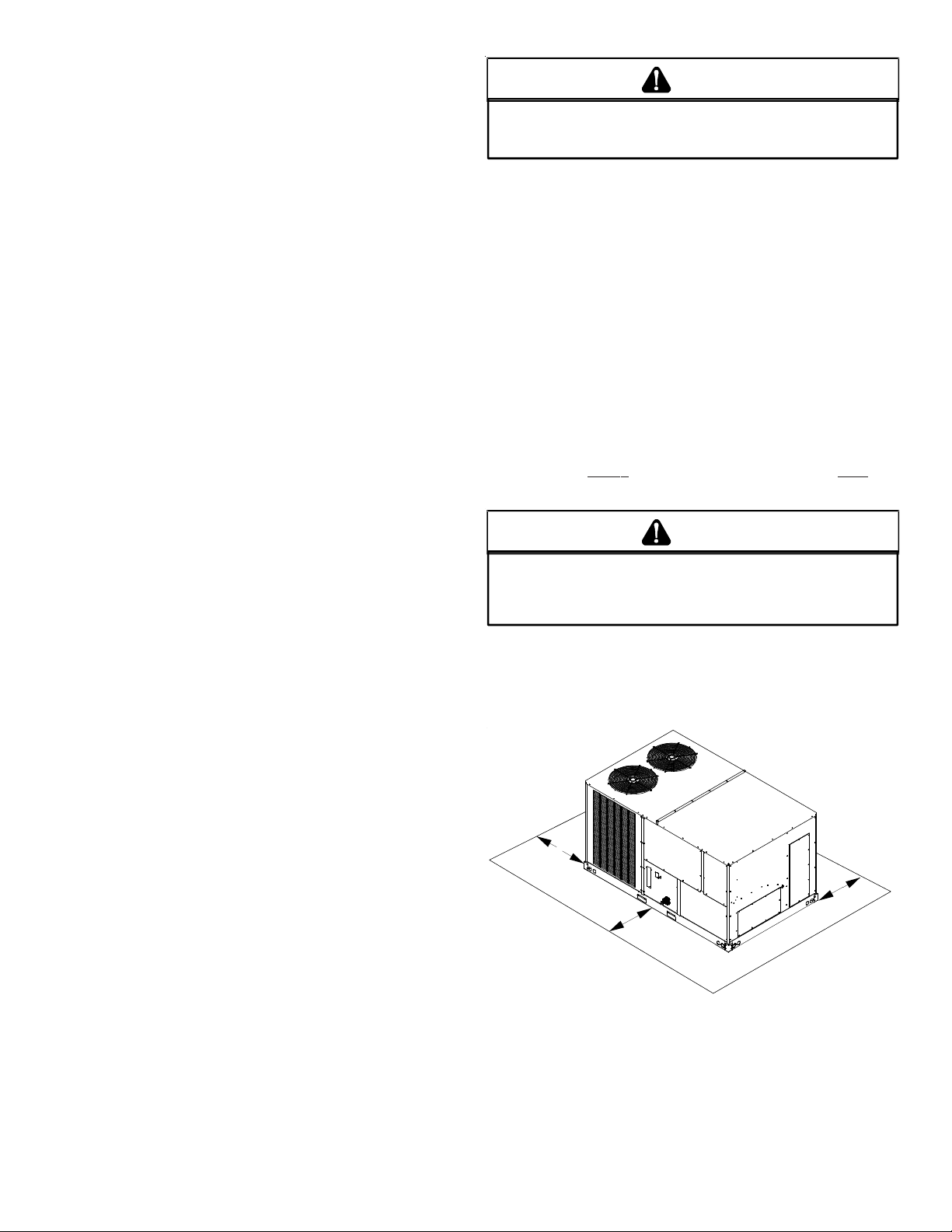
UNIT CLEARANCES
*In situations that have multiple units, a 48” minimum clearance is
required between the condenser coils.
4
Page 5
Adequate clearance around the unit should be k ept f or safe ty , ser vice, maintenance, and proper unit operation. A t otal clearance of
75” on the main control panel side of the unit is recommende d t o
facilitate possible fan shaft, coil, electric heat and gas furnace removal. A clearance of 48” is recommended on all other sides of
the unit to facilitate possible compr essor remov al, to allow service
access and to insure proper v entilation and condenser airflow . The
unit must not be installed beneath any obstruction. The unit should
be installed remote from all building exhausts to inhibit ingestion
of exhaust air into the unit fresh air intake.
CAUTION
IF
PROTRUSIONS EXIST, DO NO ATTEMPT TO SET UNIT ON CURB
.
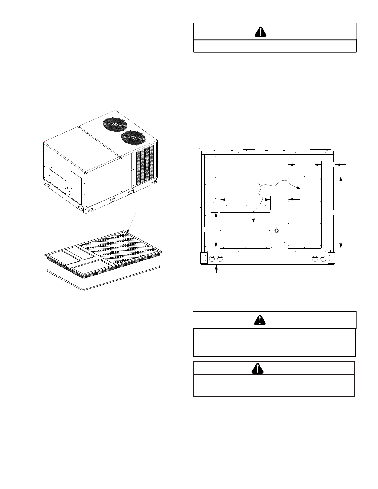
ROOF TOP DUCT CONNECTIONS
Install all duct connections on the unit before placing the unit on
rooftop.
HORIZONTAL DISCHARGE
Refer t o IOD-7006 included in the litera ture pack for inst alling horizontal duct covers.
Flexible duct connectors between the unit and ducts are recommended. Insulate and weatherproof all external ductwork and
joints as required and in accordance with local codes.
INSULATED
PANELS
Roof Curb Installation
ROOF CURB POST -INSTALLA TION CHECK S
After installation, check the top of the curb, duct connection fr ame
and duct flanges to make sure gasket has been applied properly.
Gasket should be firmly applied to the top of the curb perimeter,
duct flanges and any exposed duct connection frame. If gasket is
loose, re-apply using strong weather resistant adhesive.
5 7/8”
36 3/8”
REMOVE
COVERS
28 3/8”
13 7/8”
SUPPLY
6 1/4”
HORIZONTAL DISCHARGE DUCT CONNECTIONS
7 3/8”
12 5/8”
RETURN
RIGGING DET AILS
WARNING
O PREVENT PROPERTY DAMAGE, THE UNIT SHOULD REMAIN IN AN UPRIGHT
T
POSITION DURING ALL RIGGING AND MOVING OPERATIONS.
LIFTING AND MOVING WHEN A CRANE IS USED, PLACE THE UNIT IN AN
ADEQUATE CABLE SLING.
T
O FACILITATE
PROTRUSION
Inspect curb to ensure that none of the utility services (electric)
routed through the curb protrude above the curb.
CAUTION
DO
NOT LIFT UNITS TWO AT A TIME
INCLUDED IN THE UNIT BASE FRAME
PREVENT DAMAGE TO THE UNIT
. P
ROVISIONS FOR FORKS HAVE BEEN
. M
INIMUM FORK LENGTH IS
.
48” TO
Provisions for fork s have been include d in the unit base frame. No
other fork locations are approved.
5
Page 6
WARNING
O PREVENT POSSIBLE EQUIPMENT DAMAGE, PROPERTY DAMAGE, PERSONAL
T
INJURY OR DEATH, THE FOLLOWING BULLET POINTS MUST BE OBSERVED
WHEN INSTALLING THE UNIT.
• Unit must be lifted by the four lifting holes located at the
base frame corners .
• Lifting c ables should be at tached to the unit with shackle s.
• The distance between the crane hook and the top of the
unit must not be less than 60”.
• Two spreader bars must span over the unit to prevent
damage to the cabinet by the lift cables. Spreader bars
must be of sufficient length so that cables do not come in
contact with the unit during transport. Remove wood
struts mounted beneath unit base fr ame befor e setting unit
on roof curb. These struts are intended to protect unit
base frame from f ork lift damage. Removal is acc omplished
by extracting the sheet metal retainers and pulling the
struts through the base of the unit. Refer to rigging label
on the unit.
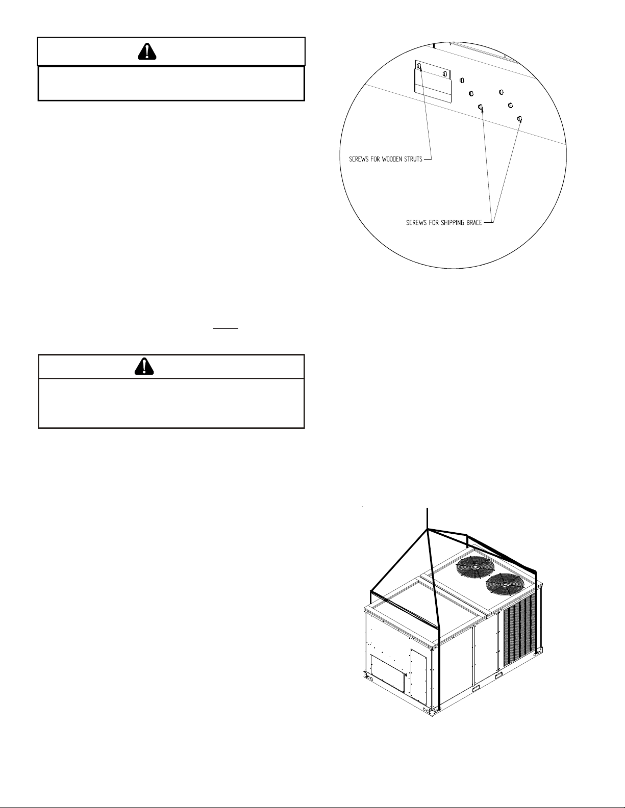
• Your unit may be equipped with a steel shipping brace
located underneath the unit (under compressors). If
installing on a roof curb, the brace MUST be removed.
Follow the following instructions for removal.
CAUTION
W
HEN UNIT IS SUSPENDED, BOARDS AND SHIPP ING BRACE WILL DROP WHEN
SCREWS ARE REMOVED
EMOVE FORK HOLE BRACKETS, BOARDS AND SHIPP ING BRACE FROM BOTTOM
R
OF UNIT BEFORE PLACING UNIT ONTO CURB
Before installing this unit on a roof curb:
1. Remove wooden strut s per installation instructions. These
are the struts that are located in the fork holes and are
used to protect the unit from damage while lifting with
forks.
2. Locate and remove the twelve (12) scr ews tha t at tach the
shipping brace to the side r ails. There will be six (6) screws
on each side of the unit and they are in a diagonal pat tern.
See following figure.
. TO
PREVENT PERSONAL INJURY
, STAND CLEAR.
.
3. Lift unit per the “Rigging Details” section of the installation
instructions, observing all warnings and cautions. Lift the
unit high enough off the ground to reach under and gr asp
the shipping brace.
4. Rotate the brace by tapping the ends until the brace falls
free from the unit.
5. Dispose of the brace appropriately.
Important: If using bottom discharge with roof curb, ductwork
should be attached to the curb prior to ins talling the unit. Ductwork
dimensions are shown in Roof Curb Installation Instructions.
Refer to the R oof Curb Installation Instructions for proper curb installation. Curbing must be installed in compliance with the National Roofing Contractors Association Manual.
Lower unit carefully onto roof mounting curb. While rigging unit,
center of gravity will cause condenser end t o be lower than supply
air end.
6
Page 7
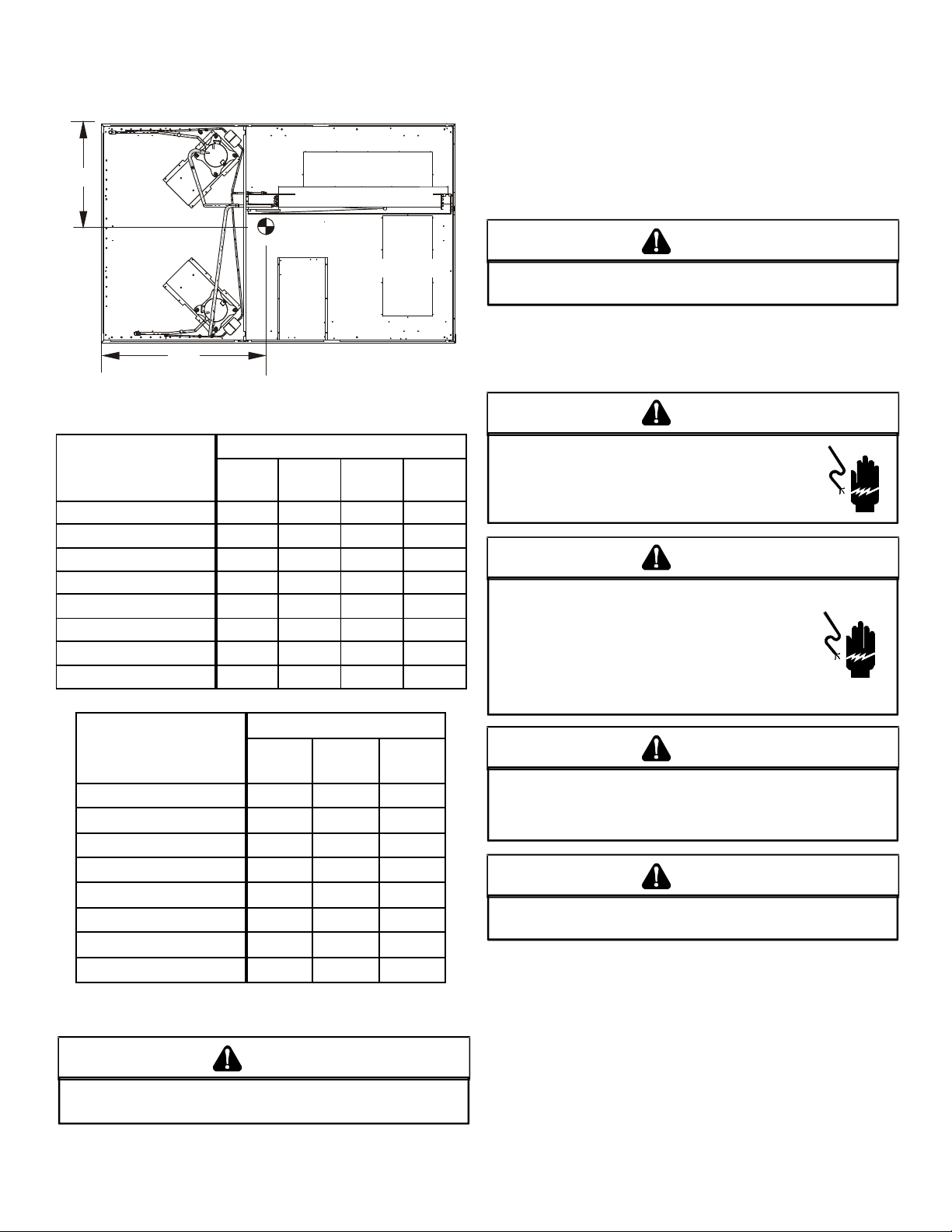
To assist in determining rigging requirements, unit weights are
A
C
shown as follows:
Bring condenser end of unit into alignment with the curb. With
condenser end of the unit resting on curb member and using curb
as a fulcrum, lower opposite end of the unit until entire unit is
seated on the curb. When a rectangular cantilever curb is used,
care should be taken to center the unit. Check for proper alignment and orientation of supply and return openings with duct.
Y
EVAP ORATOR COIL
COMPRESSOR 1
CG
COMPRESSOR 2
RETURN
SUPPLY
RIGGING REMOVAL
CAUTION
TO
PREVENT DAMAGE TO THE UNIT, DO NOT ALLOW CRANE HOOKS
AND SPREADER BARS TO REST ON THE ROOF OF THE UNIT
Remove sprea der bars, lifting cable s and other rigging equipment.
BD
X
CORNER & CENTER OF GRAVITY LOCATIONS
ELECTRICAL WIRING
WARN ING
.
DCC Weights (lb s)
DATA
090 102 120 150
Corner Weight - A 313 310 310 420
Corner Weight - B 248 263 263 335
Corner Weight - C 250 258 258 290
Corner Weight - D 199 219 219 230
Unit Shipping Weight 1085 1125 1125 1300
Unit Operating Weight 1010 1050 1050 1275
X (I nche s) 4 4 45 45 41
Y (Inches) 27 28 28 27.5
DCH Weights (lbs)
DATA
090 102/120 150
Corn er W eight - A 28 5 345 4 35
Corn er W eight - B 285 325 3 45
Corn er W eight - C 285 320 3 00
Corn er W eight - D 285 300 2 40
Unit Ship ping W e ig ht 1175 1 3 10 1 3 50
Unit Operating Weight 1135 1285 1325
X (I nc hes) 4 8 48 41
Y (Inches) 30 30 27.5
NOTE: These weights are without accessories installed.
HIGH VOLTAGE!
ISCONNECT ALL POWER BEFORE SERVICI NG OR
D
INSTALLING THIS UNIT
BE PRESENT
DAMAGE, PERSONAL INJURY OR DEATH
. F
. M
AILURE TO DO SO MAY CAUSE PROPERTY
ULTIPLE POWER SOURCES MAY
.
WARN ING
HIGH VOLTAGE!
T
O AVOID PERSONAL INJURY OR DEATH DUE TO
ELECTRICAL SHOCK, DO NOT TAMPER WITH FACTORY
WIRING
. THE
OF THESE UNITS ARE FACTORY-INSTALLED AND HAVE
BEEN THOROUGHLY TESTED PRIOR TO SHIPMENT
ONTACT YOUR LOCAL REPRESENTATIVE IF
C
ASSISTANCE IS REQUIRED
INTERNAL POWER AND CONTROL WIRING
.
.
CAUTION
TO
PREVENT DAMAGE TO THE WIRING, PROTECT WIRING FROM
SHARP EDGES
LOCAL CODES AND ORDINANCES
REMOVABLE ACCESS PANELS
. F
OLLOW NATIONAL ELECTRICAL CODE AND ALL
. DO
NOT ROUTE WIRES THROUGH
.
CAUTION
C
ONDUIT AND FITTINGS MUST BE WEATHER-TIGHT TO PREVENT
WATER ENTRY INTO THE BUILDING
.
For unit protection, use a fuse or HACR circuit breaker that is in
excess of the circuit ampacity, but less than or equal to the maximum overcurrent protection device. DO NOT EXCEED THE MAXIMUM OVERCURRENT DEVICE SIZE SHOWN ON UNIT DATA PLATE.
CAUTION
TO
PREVENT SEVERE DAMAGE TO THE BOTTOM OF THE UNIT, DO NOT
FORK LIFT UNIT AFTER WOOD STRUTS HAVE BEEN REMOVED
.
All line voltage connections must be made through weatherproof
fittings. All exterior power supply and ground wiring must be in
approved weatherproof conduit.
7
Page 8
The main power supply wiring to the unit and low voltage wiring
to accessory controls must be done in accordance with these instructions, the latest e dition of the National Electrical Code (ANSI/
NFP A 7 0), and all local codes and ordinances. All field wiring shall
conform with the temperature limitations for Type T wire (63°F/
35°C rise).
The main power supply shall be three-phase, three wir e. The unit
is factory wired for the voltage shown on the unit’s data plate.
POWER
WIRING
NOTE: If supply voltage is 208V , all le ads on primary of transf ormer
TRANS1 must be moved from the 230V to the 208V tap.
Main power wiring should be sized f or the minimum wire ampacity
shown on the unit’s data plate. Size wires in accordance with the
ampacity tables in Article 310 of the National Electrical Code. If
long wires are required, it may be necessary to increase the wire
size to prevent e xcessiv e volt age drop. Wires should be sized f or a
maximum of 3% voltage drop.
CAUTION
O AVOID PROPERTY DAMAGE OR PERSONAL INJURY DUE TO FIRE, USE
T
ONLY COPPER CONDUCTORS.
CAUTION
L
ABEL ALL WIRES PRIOR TO DISCONNECTION WHEN SERVICING
CONTROLS
DANGEROUS OPERATION
SERVICING
. W
IRING ERRORS CAN CAUSE IMPROPER AND
.
. V
ERIFY PROPER OPERATION AFTER
NOTE: A weather-tight disconnect switch, properly sized for the
unit total load, must be field or f actory inst alled. An e xt ernal field
supplied disconnect may be mounted on the exterior panel.
Ensure the data plate is not cov ered by the field-supplied disc onnect
switch.
• Some disconnect switches are not fused. Pr otect the power
leads at the point of distribution in accordance with the
unit’s data plate.
• The unit must be electrically grounded in accor dance with
local codes or, in the absence of local codes, with the lates t
edition of the National Electrical Code (ANSI-NFPA 70). A
ground lug is provided for this purpose. Size grounding
conductor in accordance with T able 250-95 of the National
Electrical Code. Do not use the ground lug for c onnecting
a neutral conductor.
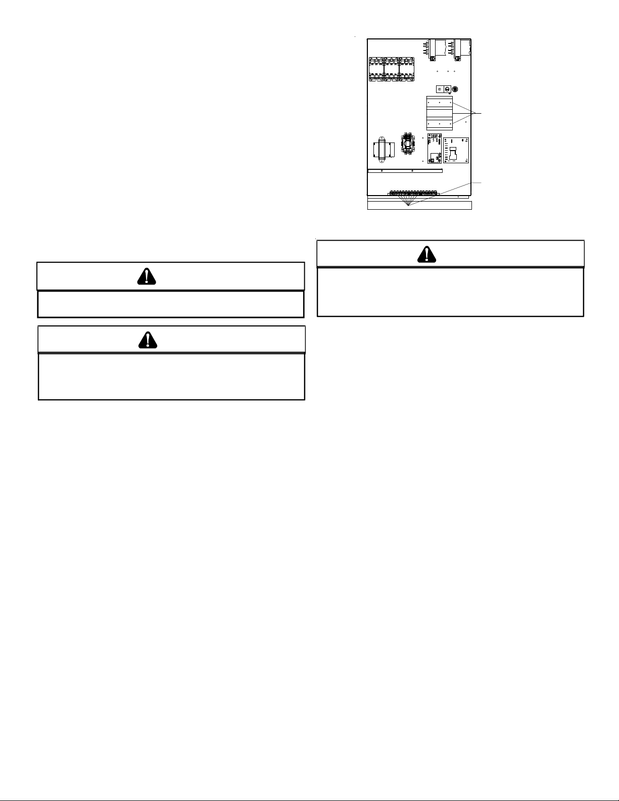
• Connect power wiring to the Single Point Power block. This
terminal block is located within the main control box.
COM
NO
NC
THERMOSTAT
WIRING
POWER AND LOW VOLTAGE BLOCK LOCATIONS
WARN ING
F
AILURE OF UNIT DUE TO OPERATION ON IMPROPER LINE VOLTAGE
OR WITH EXCESSIVE PHASE UNBALANCE CONSTITUTES PRODUCT
ABUSE AND WILL VOID YOUR WARRANTY AND MAY CAUSE SEVERE
DAMAGE TO THE UNIT ELECTRICAL COMPONENTS
.
Areas Without Convenience Outlet
It is recommended that an independent 115V power source be
brought to the vicinity of the roof top unit for portable lights and
tools used by the service mechanic.
NOTE: Refer to local codes for requirements. These outlets can
also be factory installed.
UNITS INSTALLED ON ROOF TOPS
Main power and low voltage wiring may enter the unit through
the side or through the roof curb. Install conduit connect ors at the
desired entr ance locations. External connector s must be weather proof. All holes in the unit base must be sealed (including those
around conduit nuts) to prevent water leakage into building. All
required conduit and fittings are to be field supplied.
Supply voltage to roof top unit mus t not vary by more than 10% of
the value indicated on the unit’s data plate. Phase voltage unbalance must not exceed 2%. Contact your local power comp any for
correction of improper voltage or phase unbalance.
8
Page 9

DIMPLES MA RK DRILL LOCATIONS
HIGH VOLTAGE EN TRANCE
10 3/16”
LOW VOLTAGE ENTRANC E
26 ½”
ELECTRICAL ENTRANCE LOCATIONS
Unit is equipped with Single Point Power Block and Low Voltage
Block.
LOW VOLTAGE CONTROL WIRING
1. A 24V thermostat must be installed for unit operation. It
may be purchased with the unit or field -supplied.
Thermostats may be programmable or electromechanic al
as required.
2. Locate thermostat or remote sensor in the conditioned
space where it will sense average temperature. Do not
locate the device where it may be directly exposed to
supply air, sunlight or other sources of heat. Follow
installation instructions packaged with the thermostat.
3. Use #18 AWG wire for 24V control wiring runs not
exceeding 75 feet. U se #16 A WG wire for 24V con trol wiring
runs not exceeding 125 feet. Use #14 AWG wire for 24V
control wiring runs not exceeding 200 feet. Low voltage
wiring may be National Electrical Code (NEC) Class 2 where
permitted by local codes.
4. Route thermostat wires from sub-base terminals to the
unit. Control wiring should enter through the duct panel
(dimple marks entrance location). Connect thermostat and
any accessory wiring to low voltage terminal block TB1 in
the main control box.
CIRCULATING AIR AND FILTERS
DUCTWORK
The supply duct from the unit through a wall may be ins talled without clearance. However, minimum unit clearances must be maintained (see “Clearance s” section). The supply duct should be provided with an access panel large enough to inspect the air chamber downstream of the heat exchanger. A cover should be tightly
attached to pr event air leaks.
Ductwork dimensions are shown in the roof curb installation
manual.
If desired, supply and return duct connections to the unit may be
made with flexible connections to reduce possible unit operating
sound transmission.
CONDENSA TE DRAIN CONNE CTION
CONDENSATE DRAIN CONNECTION
A 3/4” female NPT drain connection is supplied on the end of the
unit and bottom of the drain pan f or condensat e piping. An e xter nal trap must be installed for proper condensate drainage.
DRAIN
CONNECTION
UNIT 2" MINIMUM
FLEXIBLE
TUBING-HOSE
OR PIPE
A POSITIVE LIQUID
SEAL IS REQUIRED
Drain Connection
3" MIN IMUM
Install condensate drain trap as shown. Use 3/4” drain line and
fittings or larger. Do not operate without trap.
HORIZONTAL DRAIN
Drainage of condensate directly on to the r oof ma y be accept able;
refer to local code. It is recommended that a small drip pad of either stone, mortar , w ood or metal be provide d to prevent an y possible damage to the roof.
NOTE: Field-supplied conduit may nee d t o be installed depending
on unit/curb configuration. Use #18 AWG solid conductor wire
whenever connecting thermostat wire s to terminals on sub-ba se.
DO NOT use larger than #18 AWG wire. A transition to #18 AWG
wire may be requir e d be fore entering thermostat sub-base.
NOTE: Refer to unit wiring diagrams for thermostat hookups.
CLEANING
Due to the fact that drain pans in any air conditioning unit
will have some moisture in them, algae and fungus will
grow due to airborne bacteria and spores. Periodic cleaning is necessary to prevent this build-up from plugging the
drain.
9
Page 10

ST ARTUP, ADJUSTMENTS, AND CHECK S
WARN ING
the warranty. After the machines are used for temporary heating
or cooling, inspect the coils, fans, and motors for unacceptable
levels of construction dust and dirt and install new filters.
HIGH VOLTAGE!
O AVOID PERSONAL INJURY OR DEATH DUE TO
T
ELECTRICAL SHOCK, B
THE BUILDING ELECTRICAL GROUND BY USE OF THE
GROUNDING TERMINAL PROVIDED OR OTHER
ACCEPTABLE MEANS
SERVICING OR INSTALLING THIS UNIT
OND THE FRAME OF THIS UNIT TO
. D
ISCONNECT ALL POWER BEFORE
.
PRE-STARTUP INSTRUCTIONS - GENERAL
CAUTION
TO
PREVENT PROPERTY DAMAGE OR PERSONAL INJURY
START THE UNIT UNTIL ALL NECESSARY PRE-CHECKS AND TESTS
HAVE BEEN PERFORMED
.
, DO
NOT
Prior to the beginning of Startup, Adjustments, and Checks pr ocedures, the following steps should be completed in the building.
Prior to the beginning of Starup, Adjustments, and checks
proceudres, the following steps should be completed in the
building.
WARNING
MOVING MACHINERY HA ZARD !
\
T
O PREVENT POSSIBLE PERSONAL INJURY OR DEATH, DISCONNECT
POWER TO THE UNIT AND PADLOCK IN THE
SERVICNG FANS
.
“OFF”
POSITION BEFORE
HEATING STARTUP
On new installations, or if a major component has been replaced,
the operation of the unit must be checked.
Check unit operation as outlined in the following instructions. If
any sparking, odors, or unusual sounds are encountered, shut off
electrical power and recheck for wiring errors, or obstructions in
or near the blower motors. Duct covers must be removed before
operating unit.
CONTRACTOR RESPONSIBILITY
The installing contractor must be certain that:
• All supply and return air ductwork is in place, properly
sealed, and corresponds with installation instructions.
• All thermostats are mounted and wired in accordance
with installation instructions.
• All electric power, all gas, hot water or steam line
connections, and the condensate drain ins tallation ha ve
been made to each unit on the job. These main supply
lines must be functional and capable of operating all unit s
simultaneously.
• Air filters are in place.
ROOF CURB INSTALLATION CHECK
Inspect the roof curb for correct installation. The unit and curb
assembly should be level. Inspect the flashing of the roof mounting curb to the roof, especially at the corners, for good workmanship. Also check for leaks around g a s kets. Note any deficiencies in
a separate report and forward to the contractor.
OBSTRUCTIONS, FAN CLEARANCE AND WIRING
Remove any extraneous construction and shipping materials that
may be found during this procedure. Rotate all fans manually to
check for proper clearances and that they rotate freely. Check for
bolts and screws that may have jarred loose during shipment to
the job site. Retighten if necessar y. Re-tighten all electrical connections.
FIELD DUCT CONNECTIONS
Verify that all duct connections are tight and that there is no air
bypass between supply and return.
FILTER SECTION CHECK
Remove filter section access panels and check that filter s are properly installed. Note airflow arrows on filter frames.
The Startup, Adjustments, and Checks procedure provides a s tepby-step sequence which, if follow ed, will assure the proper st artup
of the equipment in the minimum amount of time. Air balancing
of duct system is not considered part of this procedure. However,
it is an important phase of any air conditioning s yst em startup and
should be performed upon completion of the Startup, Adjustments ,
and Checks procedure. The St artup, Adjustment s, and Checks procedure at outside ambients below 55°F should be limit ed to a readiness check of the refrigera tion system with the requir ed final check
and calibration left to be completed when the outside ambient
rises above 55°F.
TEMPORARY HEATING OR COOLING
If the unit is to be used for tempor ary heating or cooling, a “Startup,
Adjustments, and Checks” must first be performed in accordance
with this manual. Failure to comply with this requir ement will void
PRE-STARTUP PRECAUTIONS
It is important to your safety that the unit has been properly
grounded during installation. Check gr ound lug connection in main
control box for tightness prior to closing circuit break er or disconnect switch. Verify that supply voltage on line side of disconnect
agrees with voltage on unit identification plate and is within the
utilization voltage rang e as indicate d in Appendix B Electrical Data.
System Voltage - That nominal voltage value assigned to a circuit
or system for the purpose of designating its voltage cla ss.
Nameplate Voltage - That voltage assigned to a piece of equipment for the purpose of designating its voltage class and for the
purpose of defining the minimum and maximum voltage at which
the equipment will operate.
10
Page 11

Utilization Voltage - The voltag e of the line terminals of the equipment at which the equipment must give fully satisfactory performance. Once it is establishe d that supply voltag e will be maintained
within the utilization range under all sy stem conditions, check and
calculate if an unbalanced condition exist s between phases. Calculate percent voltage unbalance as follows:
Three Phase Models Only
2) MAXIMUM VOLTAGE DEVIATIONS
3) PERCENT VOLTAGE
UNBALANCE
HOW TO USE THE FORMULA:
EXAMPLE: With voltage of 220, 216, and 213
1) Average Voltage = 220+216+213=649 / 3 = 216
2) Maximum Voltage Deviation s fro m Average Voltage = 220 - 216 = 4
3) Percent Voltage Unbalance = 100 x = = 1.8%
Percent voltage unbalance MUST NOT exceed 2%
= 100 X
FROM AVERAGE VOLT AG E
1) AVERAGE VOLTAGE
4
216
400
216
.
CONTROL VOLTAGE CHECK
With disconnect switch in the open “OFF” position, disconnect blue
wire from low voltage transformer TRANS1. Close the disconnect
switch to energize TRANS1 con trol transf ormer . Check primary and
secondary (24V) of control tr ansformer TRANS1.
AIR FLOW ADJUSTMENTS
EVAPORATOR FAN ROTATION CHECK (THREE PHASE MODELS ONLY)
Check that fan rotates counter-clockwise when viewed from the
drive side of unit and in accordance with r ot ation arro w shown on
blower housing. If it does not, reverse the two incoming power
cables. In this case, repeat bearing check.
Do not attempt to change load side wiring. In ternal wiring assur e s
all motors and compressors will rotate in correct direction once
evaporator fan motor rotation check has been made.
ELECTRICAL INPUT CHECK
Make preliminary check of evapor ator f an ampere dra w and verify
that motor nameplate amps are not exceeded. A final check of
amp draw should be made upon completion of air balancing of
the duct system (see Appendix B).
SET EVAPORATOR FAN RPM
Actual RPM’s mus t be set and verified with a tachomet er or strobe
light. Refer to Appendices A and B for basic unit fan RPM. Refer
also to “Airflow ” section of this manual. W ith disconnect switch
open, disconnect thermostat wires from terminals Y and W. This
will prevent heating and mechanical c ooling from coming on. Place
a jumper wire across terminals R and G at TB1 terminal block. Close
disconnect switch; evaporator fan motor will operate so RPM can
be checked.
NOTE: For 2 Spee d Models, airflow a djustmen ts mus t be made on
high speed, i.e., 2nd stage cooling or in heat mode.
The drive on the supply fan is typically set in the middle of the
RPM range. The drive motor she a v e pitch diameter is field adjustable for the required airflow. Refer to the following “Drive
Adjustments” section.
When the final adjustments are comple te, the curren t draw of the
motor should be checked and compared to the full load current
rating of the motor. The amperage must not exceed the service
factor stamped on the motor nameplate. The total airflow must
not be less than that required f or oper ation of the electric heat ers
or the furnace.
If an economizer is installe d, check the unit operating balance with
the economizer at full outside air and at minimum outside air. Upon
completion of the air flow balancing, we recommend replacing the
variable pitched motor shea ve with a properly-sized fixed sheave.
A matching fixed sheave wi ll provide longer belt and bearing life
and vibration free operation. Initially, it is best to have a variable
pitched motor sheave for the purpose of airflow balancing, but
once the balance has been achieved, fixe d sheav es maintain alignment and minimize vibration more ef fectively . For dir ect drive units,
move green wire f or fan.
START-UP PROCEDURE AND CHECKLIST FOR 2 SPEED MODELS:
Models with a V in the 11th position of the model number.
For 2 speed models, the indoor blower will operate on low speed
when in “Fan Only” mode or while in first stage “Cooling” mode.
Unit will operate on high speed in “Heating” mode and while in
second stage “Cooling” mode.
The start-up procedure is the same as for “Air Conditioning Startup Procedure” with the understanding that in Step 6, the indoor
blower will run at low speed (~1175 motor rpm) and in Step 7, the
indoor blower will operate at high speed (~1775 motor rpm).
NOTE: While in the Cooling Mode, to prevent frost from forming
on the evaporator while the unit is operating in outdoor
temperatures of 65°F or lower, it is recommended that a low
ambient kit (LAKT-**) is used. This is strongly recommended for 2
Speed models due to the lower airflow while in the first stage
cooling. To further protect the compressor from damage during
low ambient conditions, a Freez estat Kit (F SK01) can be adde d that
turns the compressor off when the evapor at or temper ature dr ops
too low.
BELT DRIVE MODELS ONLY
NOTE: On “non-two speed models” (two-speed models ha ve a “V”
in the eleventh character of the model number), never run CFM
below 300 CFM per ton. Evaporator freezing or poor unit performance is possible.
The drive on the supply fan is typically set in the middle of the
RPM range. The drive motor she a v e pitch diameter is field adjust able for the required airflo w . Ref er to “Motor She ave Adjustmens”
section.
11
Page 12

Upon completion of the air flow balancing, we rec ommend replacing the variable pitched motor sheave with a properly-sized fixed
sheave. A matching fix ed shea ve will provide longer belt and bear ing life and vibration free operation. Initially, it is best to have a
variable pitched motor sheave for the purpose of airflow balancing, but once the balance has been achieved, fixed sheaves maintain alignment and minimize vibra tion mor e e f fectively. For direct
drive units, move fan speed wire.
BEARING CHECK
Prior to energizing any f ans, check and make sure tha t all setscrews
are tight so that bearings are properly secured to shafts.
For heat pump units, the airflow must be adjusted so that the air
temperature rise f alls within the r anges giv en s tate d on Dat a Plate
(see Appendix A - Blower Performance).
TENSION AND ALIGNMENT ADJUSTMENT
Correct belt tension is very important to the life of your belt. Too
loose a belt will shorten its life; too tight, premature motor and
bearing failure will occur. Check you belt drive for adequate “runin” belt tension by measuring the force r equired to deflect the belt
at the midpoint of the span length. Belt tension f or ce can be measured using a belt tension gauge, av ailable through most belt drive
manufacturers.
S
P
A
N
L
E
N
G
T
H
*
D
E
F
L
F
O
D
C
t
E
C
T
I
O
N
R
C
E
h
H
d
TYPE
MODEL
BELT DRIVE Used New
7.5 Ton 2.6 to 3.6 3.75 +/- 0. 5 4.0 +/- 0.5 9/3 2 +/- 1/16
8.5 Ton 2.6 to 3.6 3.75 +/- 0. 5 4.0 +/- 0.5 9/3 2 +/- 1/16
10 Ton 3.0 to 4.0 3.75 +/- 0. 5 4.0 +/- 0.5 9/3 2 +/- 1/16
1 2.5 T on 2.6 to 3.6 3.75 +/- 0. 5 4.0 +/- 0.5 9/3 2 +/- 1/16
A, AX Standard
SHEAVE
DIAMETE
R (in )
DEFLECTION
FORCE (lbs)
DEFLEC TION
(in )
RECOMMENDED POUNDS OF FORCE PER BELT
When new V-belts are installed on a drive, the initial tension will
drop rapidly during the first fe w hours of use. Check tension frequently during the first 24 hours of operation. Subsequent
retentioning should fall between the minimum and ma ximum force.
To determine the deflection distance from a normal position, use
a straightedge or stretch a cord from sheave to sheave to use as a
reference line. On multiple belt drives, an adjacent undeflected
belt can be used as a ref er ence.
MOTOR SHEA VE ADJUSTMENTS
VL, VM & 2VP VARIABLE PITCH KEY TYPE MOTOR SHEAVES
The driving and driven motor sheave s should be in alignment with
each other and the shafts parallel.
VL & VM SHEAVES ADJUSTMENT
1. Loosen set screw “B” using a 5/32" Allen key.
2. Making half or full turns from closed position, adjust sheave
pitch diameter for desired speed. DO NOT OPEN MORE
THAN FIVE FULL TURNS.
3. Tighten set screw “B” securely over flat.
4. Carefully put on belts and adjust belt tension. DO NOT
FORCE BELTS OVER GROOVES.
5. Ensure all keys are in place and the se t screws tigh t befor e
starting drive. Recheck set screws and belt tension after
24 hours service.
*Apply force to the center of the span.
t = Span length, inches
C = Center distance, inches
D = Larger sheave diameter, inches
d = Smaller sheave diameter, inches
h = Deflection height, inches
DRIVE BELT TENSION ADJUSTMENT
NOTE: Future adjustments should be made by loosening the belt
tension and increasing or decreasing the pitch diameter of the
sheave by half or full turns as r equired. R eadjust belt tension be fore
starting drive.
12
Page 13

9. Turn the thermosta t system switch to “ OFF” and disconnect
all power when servicing the unit.
WARN ING
C
B
VL & VM
NOTE: Do not operate shea ve with flange projecting be yond the
hub end.
REFRIGERATION SYSTEM CHECKS
Ensure the hold-down bolts on the compressor are secure and ha ve
not vibrated loose during shipment. Check that vibration grommets have been installe d. Visually check all piping and clamps. The
entire refrigeration system has been factory charged and tested,
making it unnecessary to field charge. Factory charges are shown
on the unit nameplate.
AIR CONDITIONING START-UP PROCEDURE
Begin with power turned off at all disconnects.
1. Turn thermostat system switch to “Cool,” and fan switch
to “Auto” and turn temperature setting as high as it will
go.
2. Inspect all registers and set them to the normal open
position.
3. Turn on the electrical supply at the disconnect.
4. Turn the fan swit ch to the “ON” position. The blower should
operate after a 7-second dela y.
5. Turn the f an s witch t o “Auto” position. The blower should
stop after a 65 second delay.
6. Slowly lower the cooling temperatur e until first st age COOL
(LOW COOL) starts. The blower, both fans, and first stage
compressor should now be operating. Allow the unit to
run 10 minutes, make sure cool air is being supplied by
the unit.
7. Lower the cooling temperatur e further until second stag e
COOL (HIGH COOL) starts. The blower, both fans, and both
compressors should now be operating. Allow the unit to
run 10 minutes, make sure cool air is being supplied by
the unit.
8. Turn the temperature setting to the highest position,
stopping the unit. The indoor blower will continue to run
for 65 seconds.
HIGH VOLTAGE!
ISCONNECT ALL POWER BEFORE SERVICI NG OR
D
INSTALLING THIS UNIT
BE PRESENT
DAMAGE, PERSONAL INJURY OR DEATH
. F
. M
AILURE TO DO SO MAY CAUSE PROPERTY
ULTIPLE POWER SOURCES MAY
.
HEAT PUMP START-UP PROCEDURE
10. Check the cooling mode for the heat pump in the same
manner as above. The reversing valve is energized when
the thermostat is placed in the cooling position. A clicking
sound should be noticeable from the reversing valve. By
lowering the temperature setting to call for cooling, the
contractor is energized. The compressor, blower and fan
should then be running. After the cooling mode is checked
out, turn the thermostat system switch to “OFF”.
11. Turn the thermostat system switch to “HEAT” and fan
switch to “AUTO”.
12. Slowly raise the heating temperature setting. When the
heating first stage makes contact, stop raising the
temperature setting.. The compressor, blower and fan
should now be running with the reversing valv e in the deenergized (heating) position. After giving the unit time to
settle out, make sure the unit is supplying heated air.
13. If the outdoor ambient is abov e 80°F, the unit may trip on
its high pressure cut out when on hea ting. The compressor
should stop. The heating cycle must be thoroughly
checked, so postpone the test to another day when
conditions are more suitable but-DO NOT FAIL TO TEST.
If the outdoor ambient is low and the unit operates
properly on the heating cycle, you ma y check the pressure
cutout operation by blocking off the indoor return air un til
the unit trips.
14. If unit operates properly in the heating cycle, raise the
temperature set ting until the heating sec ond stage mak e s
contact. Supplemental resistance heat, if installed should
now come on. Make sure it operates properly.
NOTE: If outdoor thermostats are installed the outdoor
ambient must be below the set point of the se thermostats
for the heaters to operate. It may be necessary to jumper
these thermostats to check heater operation if outdoor
ambient is mild.
15. For thermostats with emer gency heat switch, return to s tep
11. The emergency heat switch is loc ated a t the bottom of
the thermostat. Move the swit ch to emergency heat. The
heat pump will stop, the blower will continue to run, all
heaters will come on and the thermostat emer g ency heat
light will come on.
16. If checking the unit in the wintertime, when the outdoor
coil is cold enough to actuate the defrost c ontr ol, observe
at least one defrost cycle to make sure the unit defrosts
completely.
13
Page 14

FINAL SYSTEM CHECKS
1. Check to see if all supply and re turn air grilles are adjus ted
and the air distribution system is balanced for the best
compromise between heating and cooling.
2. Check for air leaks in the ductwork. See Sections on
Air Flow Adjustments.
3. Make sure the unit is free of “rattles”, and the tubing in
the unit is free from excessive vibration. Also make sure
tubes or lines are not rubbing ag ainst e ach other or sheet
metal surfaces or edg es. If so, correct the trouble.
4. Set the thermostat at the appropriate setting for cooling
and heating or automatic change over for normal use.
5. Be sure the Owner is instructed on the unit oper ation, filter ,
servicing, correct thermostat operation, e t c.
REFRIGERATION PERFORMANCE CHECK
Check that compressor RLA corresponds to values shown in Appendix B. RLA draw can be much lower than values listed at low
load conditions and low ambient condensing temperatures. Values in Appendix B can slightly exceed at high load conditions and
high ambient condensing temperatures.
HEAT PUMP OPERATION
COOLING CYCLE
When the heat pump is in the cooling cycle, it operates exactly as
a Summer Air Conditioner unit. In this mode, all the charts and
data for service that apply to summer air conditioning apply t o the
heat pump. Most apply on the heating cycle except that “condenser” becomes “evaporator”, “evaporator” becomes “condenser”, “cooling” becomes “heating”.
HEATING CYCLE
The heat pump operat es in the he a ting cycle by redirecting refrigerant flow through the r efriger ant circuit e xternal to the compre ssor . This is accomplishe d with through the re versing valv e. Hot discharge vapor from the compressor is directed to the indoor coil
(evaporator on the cooling cycle) where the heat is removed, and
the vapor condenses to liquid. It then goes thr ough the expansion
device to the outdoor coil (condenser on the cooling cycle) wher e
the liquid is evaporated, and the vapor goes to the compressor.
When the solenoid valve coil is operated either from heating to
cooling or vice versa, the piston in the reversing valve to the low
pressure (high pre ssure) reverse positions in the reversing valve.
The following figures show a schematic of a he at pump on the cooling cycle and the heating cycle. In addition to a reversing valve, a
heat pump is equipped with an expansion device and check valve
for the indoor coil, and similar equipment for the outdoor coil. It is
also provided with a defrost control system.
The expansion devices are flowrator distributors and perform the
same function on the heating cycle as on the cooling cycle. The
flowrator distributors also act as check valves to allow for the reverse of refriger an t flo w.
When the heat pump is on the heating cycle, the outdoor coil is
functioning as an evaporator. The temperature of the refrigerant
in the outdoor coil must be below the temperatur e of the outdoor
air in order to extract heat from the air. Thus, the greater the difference in the outdoor temper ature and the outdoor coil temperature, the greater the he ating cap acity of the heat pump. This phenomenon is a characteristic of a heat pump. It is a good pr actice to
provide supplementary heat for all heat pump installations in areas where the temperature drops below 45° F. It is also a good
practice to provide sufficient supplementary heat to handle the
entire heating requirement should there be a component failure
of the heat pump, such as a compressor, or refrigerant leak, etc.
Since the temperature of the r efrigeran t in the outdoor coil on the
heating cycle is generally below freezing point, frost forms on the
surfaces of the outdoor coil under certain weather conditions of
temperature and relative humidity. Therefore, it is necessary to
reverse the flow of the refrigerant to provide hot gas in the outdoor coil to melt the frost accumulation. This is accomplished by
reversing the heat pump to the cooling cycle. At the same time,
the outdoor fan stops to hasten the temperature rise of the outdoor coil and lessen the time required for defrosting. The indoor
blower continues to run and the supplemen t ary heaters are energized.
14
Page 15

DEFROST CONTROL
NOTE: DCH models have one stage of mechanical heating. The defrost accumulation period will start when either first or second stage
defrost thermostat closes. Defrost termination occurs when both
thermostats open or the 10 minute cycle has completed.
During operation the power to the circuit board is controlled by a
temperature sensor, which is clamped to a feeder tube entering
the outdoor coil. Defrost timing periods of 30,60 and 90 minutes
may be selected by connecting the circuit board jumper to 30, 60
and 90 respectively. Accumulation of time for the timing period
selected starts when the sensor closes (approximately 31° F), and
when the wall thermostat calls for heat. At the end of the timing
period, the unit’s defrost cycle will be initiated provided the sensor remains closed. When the sensor opens (appro ximately 75° F),
the defrost cycle is t erminated and the timing period is rese t. If the
defrost cycle is not terminated due to the sensor temperature, a
ten minute override interrupts the unit’s defrost period.
FILTERS
CAUTION
T
O PREVENT PRO PERTY DAMAG E DUE TO FIRE AND LOSS O F
EQUIPMENT EFFICIENCY OR EQUIPMENT DAMAGE DUE TO DUST AND LINT
BUILD UP ON INTERNAL PARTS, NEVER OPERATE UNIT WITHOUT AN AIR
FILTER INSTALLED IN THE RETURN AIR SYSTEM.
Every application may r equire a differ ent frequency of replacement
of dirty filters. Filters must be replaced at least every three (3)
months during operating seasons.
Dirty filters are the most common cause of inadequat e he a ting or
cooling performance. Filter inspection should be made at least
every two months; more often if necessary because of local conditions and usage.
Dirty throwaway filters should be discarded and replaced with a
new, clean filter.
MAINTENANCE
WARN ING
HIGH VOLTAGE!
ISCONNECT ALL POWER BEFORE SERVICI NG OR
D
INSTALLING THIS UNIT
BE PRESENT
DAMAGE, PERSONAL INJURY OR DEATH
. F
. M
AILURE TO DO SO MAY CAUSE PROPERTY
ULTIPLE POWER SOURCES MAY
.
WARN ING
TO
PREVENT PERSONAL INJURY OR DEATH DUE TO IMPROPER
INSTALLATION, ADJUSTMENT, ALTERATION, SERVICE OR
MAINTENANCE, REFER TO THIS MANUAL
ASSISTANCE OR INFORMATION, CONSULT A QUALIFIED INSTALLER
SERVICE AGENCY OR THE GAS SUPPLIER
. FOR
.
ADDITIONAL
,
CAUTION
S
HEET METAL PARTS, SCREWS, CLIPS AND SIMILAR ITEMS INHERENTLY
HAVE SHARP EDGES, AND IT IS NECESSARY THAT THE INSTALLER AND
SERVICE PERSONNEL EXERCISE CAUTION
.
The Self Contained Packaged Air Conditioner and He at Pump should
operate for man y year s without exce ssive service calls if the unit is
installed properly . Howev er it is recommended that the homeowner
inspect the unit before a seasonal start up. The coils should be
free of debris so adequate airflow is achiev ed. The re turn and supply registers should be free of any ob s tructions. The filter s should
be cleaned or replaced. The se few steps will help to keep the pr oduct up time to a maximum. The Service section that follow s should
help in identifying problems if the unit does not operat e properly.
Disposable return air filters are supplied with this unit. See the
unit Specification Sheet or Technical Manual for the correct size
and part number. To remove the filte rs, remove the filter access
panel on return side of the unit.
CABINET FINISH MAINTENANCE
Use a fine gra de automotiv e wax on the c abinet finish t o maintain
the finish’s original high luster. This is especially important in installations with extended periods of direct sunlight.
CLEAN OUTSIDE COIL (QUALIFIED SERVICER ONLY)
The coil with the outside air flowing over it should be inspected
annually and cleaned as frequently a s necessary to keep the finne d
areas free of lint, hair and debris.
LUBRICATION
The fan shaft bearings , the 1 to 2 HP supply fan motors, the condenser fan motors and compressors are permanently lubricated.
FUNCTIONAL PARTS
Refer to the unit Parts Catalog for a list of functional parts. Parts
are available from your distributor.
TROUBLESHOOTING
THE FOLLOWING INFORMATION IS FOR USE BY QUALIFIED SER VICE
AGENCY ONLY: OTHERS SHOULD NOT ATTEMPT TO SERVICE THIS
EQUIPMENT.
Common Causes of Unsatisfactory Operation of Heat Pump on the
Heating Cycle.
INADEQUATE AIR VOLUME THROUGH INDOOR COIL
When a heat pump is in the heating cycle, the indoor coil is functioning as a condenser. The return air filter must always be clean,
and sufficient air volume must pass thr ough the indoor coil to prevent exce ssive discharge pressur e, and high pressure cut out.
15
Page 16

OUTSIDE AIR INTO RETURN DUCT
Do not introduce cold outside air into the return duct of a heat
pump installation. For units with 2-speed motor s, do not allow air
entering the indoor coil to drop below 65° F. Air below this temperature will cause low discharge pr e ssur e, thus low suction pre ssure, and excessive de frost cy cling resulting in lo w heating output.
It may also cause false defrosting.
UNDERCHARGE
An undercharged heat pump on the heating cycle will cause low
discharge pressure resulting in low suction pressure and frost accumulation on the outdoor coil.
POOR “TERMINATING” SENSOR CONTACT
The unit’s defrost terminating sensor must mak e good thermal contact with the outdoor coil tubing. Poor contact may not termina te
the unit’s defrost cycle quickly enough to prevent the unit from
cutting out on high discharge pressure.
MALFUNCTIONING REVERSING VALVE - THIS MAY BE DUE TO:
1. Solenoid not energized - In order to determine if the
solenoid is energized, touch the nut that holds the solenoid
cover in place with a screwdrive r. If the nut magnetically
holds the screwdriver, the solenoid is energized and the
unit is in the cooling cycle.
2. No voltage at unit’s solenoid - Check unit voltage. If no
voltage, check wiring circuit.
3. Valve will not shift:
a. Undercharged - check for leaks;
b. Valve Body Damaged - Replace valve;
c. Unit Pr operly Charge d - If it is on the he ating cycle, raise
the discharge pressur e by re stricting airflow thr ough the
indoor coil. If the valve does not shift, tap it lightly on
both ends with a screwdriver handle. DO NOT TAP THE
VALVE BODY. If the unit is on the cooling cycle, raise the
discharge pressure by restricting airflow through the
outdoor coil. If the valve does not shift after the above
attempts, cut the unit off and wait until the discharge
and suction pressure equalize, and repea t above st eps. If
the valve does not shift, replace it.
16
Page 17

APPENDIX A BLOWER PERFORMANCE DATA
BELT DRIVE - STANDARD DOWN SHO T
DCC/DCH090 STANDARD BELT DRIVE DOWN SHOT
ESP, In
O
H
2
0.1
0.3
0.5 3447 798 1.23 3049 754 0.94 2606 710 0.71
0.7 3400 848 1.33 2950 798 1.01 2474 754 0.75
0.9 3303 890 1.41 2871 848 1.11 2408 804 0.82
1.1 2838 897 1.23
012345
CFMRPMBHPCFMRPMBHPCFMRPMBHPCFMRPMBHPCFMRPMBHP CFMRPMBHP
DCC/DCH102 STANDARD BELT DRIVE DOWN SHOT
ESP, In
H
O
2
0.1
0.3
0.5 3237 841 1.29 2684 803 0.96 2453 754 0.77
0.7 3303 890 1.47 2753 847 1.09
0.9 2807 896 1.26
012345
CFMRPMBHPCFMRPMBHPCFMRPMBHPCFMRPMBHPCFMRPMBHP CFMRPMBHP
INCLUDES 2 SPEED MODELS AT HIGH SPEED
TURNS OPEN
3617 704 1.07 3293 653 0.84
3541 749 1.15 3179 704 0.88 2757 656 0.66
INCLUDES 2 SPEED MODELS AT HIGH SPEED
TURNS OPEN
3372 747 1.11 3078 703 0.91 2814 658 0.70
3187 797 1.16 2952 753 0.97 2650 703 0.73
DCC/DCH120 STANDARD BELT DRIVE DOWN SHOT INCLU DES 2 SPEED MODELS AT HIGH SPEED
ESP, In
O
H
2
0.2
0.4
0.6 4442 880 2.02 4066 830 1.63 3717 786 1.31
0.8 4001 885 1.77 3622 835 1.41
1.0 3603 890 1.55
1.2
012345
CFMRPMBHPCFMRPMBHPCFMRPMBHPCFMRPMBHPCFMRPMBHP CFMRPMBHP
4632 781 1.76 4203 742 1.41 3927 691 1.17 3510 658 0.9
4488 825 1.85 4183 783 1.54 3733 748 1.23 3512 693 1
TURNS OPEN
DCC/DCH150 STANDARD BELT DRIVE DOWN SH OT INCLUDES 2 SPEED MODELS AT HIGH SPEED
5 TURN S1 TURN 2 T U R N S0 TURNS 3 TURNS 4 TURN S
ESP
(IN W . C.) CFM B HP CFM BHP CF M BHP CFM BHP CFM BHP CFM BHP
0.2 5378 2.35 4967 1.92 4710 1.59 4512 1.33
0.4 5514 2.92 5349 2.56 4750 1.97 4583 1.71 4319 1.40 4030 1.13
0.6 5204 2.69 4919 2.27 4488 1.81 4258 1.54
0.8 4830 2.42 4649 2.09 4019 1.55
1.0 4497 2.19 4264 1.86
NOTE: Unit fact o ry shipped at 2.5 turns open. Tables represent dry coil without filter .
To compensate for filter, add 0.08" to measured E.S.P. SCFM correction for wet coil = 4%.
17
Page 18

APPENDIX A BLOWER PERFORMANCE DATA
BELT DRIVE - STANDARD HORIZONTAL
NOTE: For 2 Speed Models, blow er perf ormance da t a reflects High spee d perf ormance.
DCC/DCH090 STANDARD BELT DRIVE HORIZONTAL
ESP, In
O
H
2
CFM RPM BHP CFM RPM BHP CFM RPM BHP CFM RPM BHP CFM RPM BHP CFM RPM BHP
0.1
0.3
0.5 3780 841 1.52 3405 803 1.23 3053 753 0.94 2608 709 0.68 2225 665 0.53
0.7 3687 885 1.6 3327 847 1.29 2968 805 1.02 2423 758 0.73
0.9 3236 891 1.39 2850 852 1.1 2352 807 0.8
1.1 2713 896 1.17
DCC/DCH102 STANDARD BELT DRIVE HORIZONTAL
ESP, In
H
O
2
CFM RPM BHP CFM RPM BHP CFM RPM BHP CFM RPM BHP CFM RPM BHP CFM RPM BHP
0.1
0.3
0.5 3630 838 1.49 3255 800 1.2 2903 750 0.91 2458 706 0.65
0.7 3537 882 1.57 3177 844 1.26 2818 802 0.99
0.9 3086 888 1.36 2700 849 1.07
1.1 2563 893 1.14
012345
INCLUDES 2 SPEED MODELS AT HIGH SPEED
TURNS OPEN
450123
3625 701 1.08 3309 660 0.86
3815 797 1.44 3468 747 1.11 3177 703 0.88 2796 663 0.68
INCLUDES 2 SPEED MOD ELS AT HIGH SPEED
TURNS OPEN
3475 698 1.05 3159 657 0.83
3665 794 1.41 3318 744 1.08 3027 700 0.85 2646 660 0.65
DCC/DCH120 STANDARD BELT DRIVE HORIZONTAL INCLUDES 2 SPEED MODELS AT HIGH SPEED
ESP, In
H
O
2
CFM RPM BHP CFM RPM BHP CFM RPM BHP CFM RPM BHP CFM RPM BHP CFM RPM BHP
0.2
0.4
0.6 4467 824 1.81 4221 784 1.55 3689 741 1.18
0.8 4564 873 2.06 4170 830 1.68 3677 785 1.29
1.0 4129 875 1.81 3498 835 1.34
1.2 3558 879 1.49
012345
4497 780 1.7 4200 736 1.41 3735 691 1.06 3322 648 0.83
TURNS OPEN
4562 736 1.58 4253 691 1.29 3893 642 1
DCC/DCH150 STANDARD BELT DRIVE HORIZONTAL INCLUDES 2 SPEED MODELS AT HIGH SPEED
0 TURNS 1 TURN 2 TURNS 3 TURNS 4 TURNS 5 TURNS
ESP
(IN W.C.) CFM BHP CFM BHP CFM BHP CFM BHP CFM BHP CFM BHP
0.2 5570 2.27 4935 1.70 4584 1.36
0.4 58713.2056392.7753072.3149021.8846371.5541781.19
0.6 56103.0053582.5750512.1546031.7243411.41
0.8 5391 2.83 5010 2.33 4 799 2.00 43 93 1.61
1.0 5078 2.59 4676 2.11 4 448 1.79
1.2 4521 2.20 4226 1.83
NOTE: Unit fact o ry shipped at 2.5 turns open. Tables represent dry coil without filter.
To compensate for filter, add 0.08" to measured E.S.P. SCFM correction for wet coil = 4%.
18
Page 19

APPENDIX A BLOWER PERFORMANCE DATA
BELT DRIVE - HIGH STATIC DOWN SHO T
DCC/H0 90 DO WN SHO T HIG H S TATI C BEL T DRIVE
ESP, In
H
O
2
CFM RPM BHP CFM RPM BHP CFM RPM BHP CFM RPM BHP CFM RPM BHP CFM RPM BHP
0.9
1.1
1.3
1.5
1.7
1.9
2.1
DCC/H1 02 DO WN SHO T HIG H S TATI C BEL T DRIVE
ESP, In
O
H
2
CFM RPM BHP CFM RPM BHP CFM RPM BHP CFM RPM BHP CFM RPM BHP CFM RPM BHP
0.9
1.1
1.3
1.5
1.7
1.9
3256 1156 2.31 2939 1126 2.01
2.1
01
DO NOT
OPERATE
3381 1119 2.22 2890 1080 1.78
3089 1129 2.04
012345
3231 1116 2.19 2740 1077 1.75
3722 1063 2.25 3041 1023 1.67 2503 976 1.31
3359 1075 2.04 2540 1031 1.5
3572 1060 2.22 2891 1020 1.64
3209 1072 2.01
TURNS OPEN
4523
3401 909 1.51
3428 965 1.71 2943 915 1.3
3471 1015 1.9 3012 971 1.5 2423 920 1.12
TURNS OPEN
3251 906 1.48
3278 962 1.68 2793 912 1.27
3321 1012 1.87 2862 968 1.47
DCC/H1 20 DO WN SHO T HIG H S TATI C BEL T DRIVE INCLUDES 2 SPEED MO DELS AT HI G H SPEED
ESP, In
O
H
2
0.8
1.0
1.2
1.4
1.6
1.8
2.0
012345
CFM RPM BHP CFM RPM BHP CFM RPM BHP CFM RPM BHP CFM RPM BHP CFM RPM BHP
4513 1054 2.75 4127 1003 2.26 3568 950 1.71
4126 1064 2.52 3597 1008 1.92
4438 1116 2.97 3759 1069 2.25
3956 1124 2.55
4050 1179 3.05 3473 1132 2.32
TURNS OPEN
4435 940 2.22 4078 886 1.82
4462 997 2.47 4103 945 2.05 3539 892 1.52
DCC/H1 50 DO WN SHO T HIGH STAT IC BELT DRIVE I NCL U DES 2 SPEED MO DEL S AT HIGH SP EED
ESP, In
H
O
2
0.8
1.0
1.2
1.4
1.6
1.8
2.0
2.2
012345
CFM BHP CFM BHP CFM BHP CFM BHP CFM BHP CFM BHP
5947 4.16 5656 3.58 5376 3.12 4933 2.52
5708 3.93 5459 3.40 4950 2.79 4441 2.18
5776 4.64 5510 4.07 5245 3.48 4844 2.88 4525 2.45
5465 4.30 5199 3.74 4894 3.17 4404 2.54
5145 3.97 4871 3.41 4495 2.83
4805 3.63 4565 3.13 4142 2.55
4429 3.27 4233 2.85
TURNS OPEN
5978 3.87 5691 3.38 5324 2.81
NOTE: Unit facto ry shippe d at 2.5 turns open. Tables represent dry coil without filter.
To compensate for filter , add 0.08" t o measured E.S.P. SCFM correction for we t coil = 4%.
19
Page 20

APPENDIX A BLOWER PERFORMANCE DATA
BELT DRIVE - HIGH STATIC HORIZONTAL
DCC/H0 90 HO RIZONTAL HIGH S T AT IC BELT DR IVE
ESP, In
O
H
2
0.9
1.1
1.3
1.5
1.7
1.9
2.1
CFM RPM BHP CFM RPM BHP CFM RPM BHP CFM RPM BHP CFM RPM BHP CFM RPM BHP
012345
DO NOT
OPERATE
3388 1103 2.18 3036 1069 1.84
2959 1114 2
2527 1124 1.86
3514 1057 2.07 2949 1019 1.62
DCC/H1 02 HO RIZONTAL HIGH S T AT IC BELT DR IVE
ESP, In
O
H
2
0.9
1.1
1.3
1.5
1.7
1.9
CFM RPM BHP CFM RPM BHP CFM RPM BHP CFM RPM BHP CFM RPM BHP CFM RPM BHP
3188 1146 2.23 2809 1111 1.97
012345
3364 1054 2.04 2799 1016 1.59
3238 1100 2.15 2886 1066 1.81
TURNS OPEN
TURNS OPEN
3447 902 1.54
3398 956 1.65 3006 908 1.31
3486 1008 1.87 2960 962 1.44
3297 899 1.51
2856 905 1.28
3336 1005 1.84 2810 959 1.41
DCC/H1 20 HO RIZONTAL HIGH S T AT IC BELT DR IVE I NCL UDES 2 SPEED MO DELS AT HIGH S PEED
ESP, In
O
H
2
0.8
1
1.2
1.4
1.6
1.8
2
012345
CFM RPM BHP CFM RPM BHP CFM RPM BHP CFM RPM BHP CFM RPM BHP CFM RPM BHP
DO NOT
OPERATE
4760 1105 3.23 4071 1061 2.43 3342 1012 1.86
4364 1114 2.91 3579 1067 2.05
4587 1056 2.82 3971 1006 2.17
TURNS OPEN
4602 884 2.13
4749 940 2.44 4180 885 1.89
4251 945 2.12 3642 896 1.58
4443 1001 2.5 3744 951 1.8
DCC/H1 50 HO RI ZONT AL HIGH S T ATIC BELT DRIV E
ESP, In
O
H
2
0.8
1.0
1.2
1.4
1.6
1.8
2.0
2.2
012345
CFM BHP CFM BHP CFM BHP CFM BHP CFM BHP CFM BHP
--- --- --- --- --- --- --- --- 5858 3.51 5538 2.97
--- --- --- --- --- --- 5894 3.85 5502 3.20 5282 2.78
--- --- --- --- 5780 4.04 5570 3.55 5110 2.88 4869 2.47
--- --- 5900 4.49 5501 3.77 5312 3.33 4793 2.64 4598 2.28
5860 4.76 5514 4.08 5257 3.54 4945 3.01 4382 2.34 --- --5615 4.49 5315 3.88 5020 3.32 4504 2.66 --- --- --- --5529 4.40 4906 3.49 4601 2.96 --- --- --- --- --- --4938 3.78 4541 3.15 4222 2.65 --- --- --- --- --- ---
TURNS OPEN
NOTE: Unit factory shipped at 2.5 turns open. Tables represent dry coil without filter.
To compensate for filter , add 0.08" to me asured E.S.P. SCFM correction for wet c oil = 4%.
20
Page 21

APPENDIX B ELECTRICAL DATA
ELECTRICAL DA TA
MODELS
7.5 TON
COOLER
7.5 TON
HEAT
PUMP
8.5 TON
10 TON
VOLTAGE
VOLTAGE
(NAMEPLATE)
208/230-60-3 187 253 2 13.1 83.1 2 1/4 1.40 BD STD STATIC 1.5 5.0 2 6.0
460-60-3 414 506 2 6.1 41.0 2 1/4 0.80 BD STD STATIC 1.5 2.5 2 2.9
575-60-3 518 633 2 4.4 33 2 1/4 0.55 BD STD STATIC 1.5 2.3 2 2.4
208/230-60-3 187 253 2 13.1 83.1 2 1/4 1.40 BD STD STATIC 2.0 7.8 2 6.0
460-60-3 414 506 2 6.1 41.0 2 1/4 0.80 BD STD STATIC 2.0 3.9 2 2.9
575-60-3 518 633 2 4.4 33 2 1/4 0.55 BD STD STATIC 2.0 2.5 2 2.4
208/230-60-3 187 253 2 14.5 98.0 2 1/4 1.40 BD STD STATIC 2.0 7.8 2 6.0
460-60-3 414 506 2 6.3 55.0 2 1/4 0.80 BD STD STATIC 2.0 3.9 2 2.9
575-60-3 518 633 2 6.0 41.0 2 1/4 0.55 BD STD STATIC 2.0 2.5 2 2.4
208/230-60-3 187 253 2 16.0 110.0 2 1/3 2.40 BD STD STATIC 2.0 7.8 2.0 6.4
460-60-3 414 506 2 7.8 52.0 2 1/3 1.20 BD STD STATIC 2.0 3.9 2.0 3.0
LIMITATIONS
MIN MAX Qty RLA LRA Qty HP FLA HP FLA HP FLA
COMPRESSOR (ea)
OD FAN MOTORS
(ea)
ID MOTOR APPL
ID FAN MOTOR
(ea)
2 Speed ID Fan
Motor (ea)
12.5 TON
575-60-3 518 633 2 6.4 38.9 2 1/3 0.67 BD STD STATIC 2.0 2.5 2.0 2.4
208/230-60-3 187 253 2 22.4 149.0 2 1/3 2.40 BD STD STATIC 3.0 9.4 3.0 9.1
460-60-3 414 506 2 10.6 75.0 2 1/3 1.20 BD STD STATIC 3.0 4.7 3.0 4.3
575-60-3 518 633 2 7.70 54.0 2 1/3 0.67 BD STD STATIC 3.0 4.2 3.0 3.5
MINIMUM AIR FLOW FOR ELECT RI C HEAT
UNIT
7.5 TON
8.5 TON
10 TON
12.5 TON
HEATER KIT
MODEL NUMBER
EHK*-16 3000 3200
EHK*-30 3000 3200
EHK*-45 3000 3200
EHK*-16 3400 3400
EHK*-30 3400 3400
EHK*-45 3400 3400
EHK*-16 3500 3500
EHK*-30 3500 3500
EHK*-45 4000 4000
EHK*-16 4000 4000
EHK*-30 4300 4300
EHK*-45 4500 4500
MINIMUM CFM
Downshot
MINIMUM CFM
Horizontal
ATTENTION INSTALLING PERSONNEL
Use only the heater kit specified for each model as dictated by the table above.
21
Page 22

APPENDIX C UNIT DIMENSIONS
7.5 8.5 10 12.5
Y 52 7/8" 52 7/8" 52 7/8" 58 7/8"
99 1/8”
Y
61 3/4”
12 5/8”
5 7/8”
13 7/8”
28 3/8”
SUPPLY
6 1/4”
Horizontal Discharge
7 3/8”
RETURN
NOTE
For horizontal discharge, r emove supply and return duct cover
panels from the end of the unit. Save all washered screws.
According to the model size, remove (6 or 8) factory supplied panel clips that are secured to the base pan, behind
the filter access panel. With the insulated side of the panel
facing up, attach the clips. Place the provided gasket material completely around the perimeter of the clip side on both
panels. Place the assembled panels over the supply and return duct openings in the base pan and push down to snap
panels into place. Ensure the panel is evenly seated on the
flanges around the duct openings and the gasket is creating
a good seal.
36 3/8”
5 3/8”
6 1/2”
RETURN
SUPPL
Y
7 1/2”
Vertical Discharge (Bottom of Unit)
22
Page 23

Start-up Checklist
*Store in job file
Date: ___________________________________
Model Number: ___________________________________
Serial Number: ___________________________________
Technician: ___________________________________
Pre Start-Up
(Check each item as completed)
Verify all pack aging ma t erial ha s been r emov ed.
Remove all shipping brackets per installation instructions.
Verify the job site volt age agrees with the unit serial plate.
Verify condensa te c onnection is inst alle d per ins t alla tion instructions.
Verify pr oper clearance around the unit f or safety, service, maintenance and proper unit operation.
Verify pr oper we a therpr oofing of all ductw ork, roof curbs and electrical connections.
Location: __________________________________________
__________________________________________
__________________________________________
Unit #: __________________________________________
Check that the flue screen is in place.
Check gas piping f or leaks.
Verify g a s pressure to the unit is within the range specified on the serial plate.
Check to ensure that all fans, pulleys and wheels ar e secure.
Check for proper belt tension and alignment per installation instructions.
Check refriger ant piping for rubbing and leaks. Repair if necessary.
Check unit wiring to ensure it is not in contact with refrigerant piping or sharp metal edges.
Check all electrical connections and terminals. Tighten as needed.
Verify tha t the crankcase heaters hav e been energized for 24 hours.
Verify the scroll compressor(s) are rotating in the right direction.
Verify all acce ssorie s are installed and operating correctly.
Check filters and replace if necessary.
Verify the ins t allation of the thermos t a t.
23
9/2014
Page 24

ELECTRICA
L
Start-up Checklist
Start-Up
(Insert the values as each item is completed.)
Supply Voltage
Circuit 1 Compressor Amps
Circuit 2 Compressor Amps
Blower Amps
Condenser Fan Amps
BLOWER EXTERNAL STATIC PRESSURE
Return Air Static Pressure
Supply Air Static Pressure
Total External Static Pressure
Blower Wheel RPM
TEMPERATURES
Outdoor Air Temperature
Return Air Temperature
Co oling S upply A i r Tem p erat ure
He ating Sup p ly A ir Temperature
L1 - L2 L2 - L3 L3 - L1
L1 L2 L3
L1 L2 L3
L1 L2 L3
Fan 1Fan 2Fan 3
IN. W.C.
IN. W.C.
IN. W.C.
RPM
DB WB
DB WB
DB WB
DB
PRESSU RES
Ga s Inlet Pressure
Ga s Manifold Pressure
Superh ea t (O rific e Syst em)
Superh ea t (O rific e Syst em)
Discharge Circuit 1
Subcooling (TXV Syst em)
Discharge Circuit 2
Subcooling (TXV Syst em)
(HEAT P UM P ONLY)
Discharge Circuit 1
Discharge Circuit 2
Suction Circuit 1
Suction Circuit 2
Suction Circuit 1
Suction Circuit 2
IN. W.C.
IN. W.C. (Low Fire) IN. W.C. (High Fire)
PSIG °F
°F
PSIG °F
°F
PSIG °F
°F
PSIG °F
°F
PSIG °F
PSIG °F
PSIG °F
PSIG °F
24
 Loading...