

Page 1
I
NSTALLA TION
I
NSTRUCTIONS FOR
*CVC96 & *MVC96
T
WO-STAGE
(T ype FSP CA TEGOR Y IV Direct
or Non Direct V ent Air Furnace)
These furnaces comply with requirements embodied in the American National Standard / National Standard of Canada ANSI Z21.47·CSA-2.3
Gas Fired Central Furnaces.
s a professional installer you have an obligation to know
A
the product better than the customer . This includes all safety
precautions and related items.
Prior to actual installation, thoroughly familiarize yourself
with this Instruction Manual. Pay special attention to all
safety warnings. Often during installation or repair it is
possible to place yourself in a position which is more
hazardous than when the unit is in operation.
Remember, it is your responsibility to install the product
safely and to know it well enough to be able to instruct a
customer in its safe use.
Safety is a matter of common sense...a matter of thinking
before acting. Most dealers have a list of specific good
safety practices...follow them.
The precautions listed in this Installation Manual are intended
as supplemental to existing practices. However , if there is
a direct conflict between existing practices and the content
of this manual, the precautions listed here take precedence.
RECOGNIZE THIS SYMBOL
AS A SAFETY PRECAUTION.
*NOTE: Please contact your distributor or our website for
the applicable Specification Sheet referred to in this manual.
GAS F
Affix all manuals
adjacent to the unit.
URNACE
Installer:
T ABLE OF CONTENTS
SAFETY CONSIDERATIONS .................................... 3
SHIPPING INSPECTION ......................................... 4
ELECTROSTATIC DISCHARGE (ESD) PRECAUTIONS ................. 4
TO THE INSTALLER........................................... 4
PRODUCT DESCRIPTION ....................................... 4
FEATURES ................................................... 4
PRODUCT APPLICA TION ....................................... 5
LOCATION REQUIREMENTS & CONSIDERATIONS ........... 6
CLEARANCES AND ACCESSIBILITY ................................ 7
EXISTING FURNACE REMOVAL .................................. 7
THERMOSTAT LOCATION ....................................... 9
COMBUSTION & VENTILATION AIR REQUIREMENTS ................ 9
INSTALLATION POSITIONS .................................... 9
HORIZONTAL APPLICATIONS & CONSIDERATIONS ........10
FURNACE SUSPENSION........................................10
FRONT COVER PRESSURE SWITCH TUBE LOCATION ..............10
DRAIN TRAP AND LINES ......................................10
LEVELING ..................................................10
ALTERNATE VENT/FLUE AND COMBUSTION AIR CONNECTIONS ....10
AL TERNATE ELECTRICAL AND GAS LINE CONNECTIONS............11
DRAIN PAN .................................................11
FREEZE PROTECTION .........................................11
PROPANE GAS/HIGH ALTITUDE INSTALLATIONS ..........11
VENT/FLUE PIPE & COMBUSTION AIR PIPE ................12
DUAL CERTIFICATION: NON-DIRECT/DIRECT VENT ..............12
MATERIALS AND JOINING METHODS ............................12
PROPER VENT/FLUE AND COMBUSTION AIR PIPING PRACTICES ....13
TERMINATION LOCATIONS .....................................13
CANADIAN VENTING REQUIREMENTS ............................14
STANDARD FURNACE CONNECTIONS ............................14
VENT/FLUE PIPE ...........................................14
COMBUSTION AIR PIPE DIRECT VENT INSTALLATION...............14
NON-DIRECT VENT (SINGLE PIPE) PIPING .....................16
VENT/INTAKE TERMINATIONS FOR INSTALLATION
MULTIPLE DIRECT VENT FURNACES ....................19
OF
CONCENTRIC VENT TERMINATION ..............................19
SIDE WALL VENT KIT .......................................19
CONDENSATE DRAIN LINES & DRAIN TRAP ................19
GENERAL DRAIN INFORMATION ................................19
FIELD SUPPLIED DRAIN ......................................20
UPFLOW MODEL INSTALLED VERTICALLY .......................20
DRAIN EXITING RIGHT SIDE...................................20
DRAIN EXITING LEFT SIDE ....................................20
UPFLOW MODEL INSTALLED HORIZONTALLY
RIGHT SIDE DOWN ...............................21
WITH
UPFLOW MODEL INSTALLED HORIZONTALLY WITH LEFT SIDE DOWN .21
COUNTERFLOW MODEL INSTALLED VERTICALLY..................22
IOG-2008A
12/14
www.goodmanmfg.com • www.amana-hac.com
is a registered trademark of Maytag Corporation or its related companies and is used under license. All rights reserved.
5151 San Felipe Suite 500
Houston, TX 77056
© 2014 Goodman Manufacturing Company, L.P.
Page 2

DRAIN EXITING LEFT SIDE ....................................22
DRAIN EXITING RIGHT SIDE...................................22
COUNTERFLOW MODEL INSTALLED HORIZONTALLY
RIGHT SIDE DOWN ...............................22
WITH
COUNTERFLOW MODEL INSTALLED HORIZONTALLY
LEFT SIDE DOWN ................................23
WITH
ELECTRICAL CONNECTIONS .................................23
WIRING HARNESS ...........................................23
115 VOLT LINE CONNECTIONS ...............................23
J
UNCTION BOX RELOCATION ..................................24
24 VOLT THERMOST AT WIRING ...............................24
SINGLE-STAGE HEATING THERMOSTAT APPLICATION ..............25
24 VOLT DEHUMIDISTAT WIRING ..............................25
FOSSIL FUEL APPLICATIONS ...................................26
115 VOLT LINE CONNECTION OF ACCESSORIES
(HUMIDIFIER AND ELECTRONIC AIR CLEANER) .............26
AUXILIARY ALARM SWITCH:...................................28
GAS SUPPL Y AND PIPING......................................28
HIGH ALTITUDE DERATE......................................28
PROPANE GAS CONVERSION ...................................28
GAS PIPING CONNECTIONS ....................................29
PROP ANE GAS TANKS AND PIPING .............................31
CIRCULATING AIR & FILTERS ................................32
DUCT WORK - AIR FLOW ....................................32
CHECKING DUCT STATIC ......................................32
BOTTOM RETURN AIR OPENING [UPFLOW MODELS] ............33
FILTERS - READ THIS SECTION BEFORE INSTALLING
THE RETURN AIR DUCT WORK ..........................33
UPRIGHT INST ALLATIONS ......................................34
HORIZONTAL INST ALLATIONS ...................................34
ST ARTUP PROCEDURE & ADJUSTMENT .....................34
DRAIN TRAP PRIMING ........................................34
FURNACE OPERATION ........................................34
GAS SUPPLY PRESSURE MEASUREMENT .........................35
GAS MANIFOLD PRESSURE MEASUREMENT AND ADJUSTMENT ......37
GAS INPUT RATE MEASUREMENT (NATURAL GAS ONLY).........37
TEMPERA TURE RISE ..........................................38
CIRCULATOR BLOWER SPEEDS .................................38
BLOWER HEAT OFF DELAY TIMINGS ...........................41
COMFORTNET™ SYSTEM .....................................41
OVERVIEW .................................................41
AIRFLOW CONSIDERATIONS ....................................41
FOSSIL FUEL APPLICATIONS ................................... 42
CTK0* WIRING .................................................42
COMFORTNET SYSTEM ADVANCED FEATURES....................43
FURNACE ADVANCED FEATURES MENUS ........................44
THERMOSTAT MENU .........................................46
DIAGNOSTICS ................................................46
NETWORK TROUBLESHOOTING .................................46
SYSTEM TROUBLESHOOTING...................................47
NORMAL SEQUENCE OF OPERATION........................47
POWER UP .................................................47
HEA TING MODE .............................................47
COOLING MODE ............................................ 47
FAN ONLY MODE ...........................................48
OPERATIONAL CHECKS ....................................... 48
SAFETY CIRCUIT DESCRIPTION.............................. 48
INTEGRATED CONTROL MODULE ..............................48
PRIMARY LIMIT ..............................................48
AUXILIAR Y LIMIT .............................................48
ROLLOUT LIMIT ............................................. 48
PRESSURE SWITCHES .........................................49
FLAME SENSOR .............................................49
TROUBLESHOOTING ..........................................49
ELECTROSTATIC DISCHARGE (ESD) PRECAUTIONS ................49
DIAGNOSTIC CHART ..........................................49
RESETTING FROM LOCKOUT ..................................49
MAINTENANCE .................................................49
ANNUAL INSPECTION .........................................49
FILTERS ....................................................50
BURNERS ...................................................50
INDUCED DRAFT AND CIRCULATOR BLOWERS ....................50
CONDENSATE TRAP AND DRAIN SYSTEM
(QUALIFIED SERVICER ONLY) ...........................50
FLAME SENSOR (QUALIFIED SERVICER ONLY) ..................50
FLUE PASSAGES (QUALIFIED SERVICER ONLY) ..................51
BEFORE LEAVING AN INSTALLATION ........................ 51
REP AIR AND REPLACEMENT PARTS..........................51
DIP SWITCHES.................................................52
STATUS CODES ................................................ 53
TROUBLESHOOTING CHART .................................54
WIRING DIAGRAM ............................................. 59
SPECIAL INSTRUCTIONS FOR PRODUCTS INSTALLED .... 6 0
IN THE STATE OF MASSACHUSETTS........................60
G
OODMAN
INSTALL OR PERFORM SERVICE ON THIS UNIT, YOU ASSUME RESPONSIBILITY FOR ANY PERSONAL INJURY OR PROPERTY DAMAGE WHICH MAY RESULT
M
WILL NOT BE RESPONSIBLE FOR ANY INJURY OR PROPERTY DAMAGE ARISING FROM IMPROPER SERVICE OR SERVICE PROCEDURES
ANY JURISDICTIONS REQUIRE A LICENSE TO INSTALL OR SERVICE HEATING AND AIR CONDITIONING EQUIPMENT
. IF
YOU
.
.
2
Page 3

S
AFETY
C
ONSIDERATIONS
Adhere to the following warnings and cautions when installing, adjusting, altering, servicing, or operating the furnace.
T o ensure proper installation and operation, thoroughly read
this manual for specifics pertaining to the installation and
application of this product.
This furnace is manufactured for use with natural gas. It
may be field converted to operate on L.P. gas by using the
appropriate L.P. conversion kit listed in the PROPANE GAS/
HIGH ALTITUDE INSTALLATIONS section of this manual
Install this furnace only in a location and position as speci-
LOCATION REQUIREMENTS & CONSIDERA TIONS sec-
fied in
tion and INSTALLATION POSITIONS section of this manual.
Provide adequate combustion and ventilation air to the furnace as specified in COMBUSTION & VENTILATION AIR RE-
QUIREMENTS section of this manual.
Combustion products must be discharged to the outdoors.
Connect this furnace to an approved vent system only, as
specified in
VENT/FLUE PIPE & COMBUSTION AIR PIPE sec-
tion of this manual.
Never test for gas leaks with an open flame. Use a commer-
cially available soap solution made specifically for the detection of leaks to check all connections, as specified in GAS
SUPPL Y AND PIPING section of this manual.
Always install a furnace to operate within the furnace’ s intended temperature-rise range with a duct system which has
external static pressure within the allowable range, as specified on the furnace rating plate and OPERATIONAL CHECKS
section of these instructions.
When a furnace is installed so that supply ducts carry air
circulated by the furnace to areas outside the space containing the furnace, the return air shall also be handled by duct(s)
sealed to the furnace casing and terminating outside the
space containing the furnace.
A gas-fired furnace for installation in a residential garage
must be installed as specified in the LOCATION REQUIRE-
MENTS AND CONSIDERA TIONS section of this manual.
WARNING
TO
PREVENT PERSONAL INJURY OR DEATH DUE TO IMPROPER
INSTALLATION, ADJUSTMENT, ALTERATION, SERVICE OR MAINTENANCE
REFER TO THIS MANUAL
INFORMATION, CONSULT A QUALIFIED INSTALLER, SERVICER AGENCY OR
THE GAS SUPPLIER
. FOR
ADDITIONAL ASSISTANCE OR
.
WARNING
IF
THE INFORMATION IN THESE INSTRUCTIONS IS NOT FOLLOWED
EXACTLY, A FIRE OR EXPLOSION MAY RESULT CAUSING PROPERTY
,
DAMAGE
PERSONAL INJURY OR LOSS OF LIFE
DO
NOT STORE OR USE GASOLINE OR OTHER FLAMMABLE VAPORS AND
LIQUIDS IN THE VICINITY OF THIS OR ANY OTHER APPLIANCE
.
.
WHAT TO DO IF YOU SMELL GAS:
D
O NOT TRY TO LIGHT ANY APPLIANCE
D
O NOT TOUCH ANY ELECTRICAL SWITCH; DO NOT USE ANY PHONE
IN YOUR BUILDING
I
MMEDIATELY CALL YOUR GAS SUPPLIER FROM A NEIGHBOR’S
PHONE
. F
I
F YOU CANNOT REACH YOUR GAS SUPPLIER, CALL THE FIRE
DEPARTMENT
I
NSTALLATION AND SERVICE MUST BE PERFORMED BY A QUALIFIED
INSTALLER, SERVICE AGENCY OR THE GAS SUPPLIER
.
OLLOW THE GAS SUPPLIER’S INSTRUCTIONS
.
.
.
.
WARNING
T
HIS PRODUCT CONTAINS OR PRODUCES A CHEMICAL OR CHEMICALS
WHICH MAY CAUSE SERIOUS ILLNESS OR DEATH AND WHICH ARE
KNOWN TO THE STATE OF CALIFORNIA TO CAUSE CANCER, BIRTH
DEFECTS OR OTHER REPRODUCTIVE HARM
.
WARNING
H
EATING UNIT SHOULD NOT BE UTILIZED WITHOUT REASONABLE
ROUTINE, INSPECTION, MAINTENANCE AND SUPERVISION
BUILDING IN WHICH ANY SUCH DEVICE IS LOCATED WILL BE VACANT
CARE SHOULD BE TAKEN THAT SUCH DEVICE IS ROUTINELY INSPECTED
MAINTAINED AND MONITORED. IN THE EVENT THAT THE BUILDING
MAYBE EXPOSED TO FREEZING TEMPERATURES AND WILL BE VACANT
ALL WATER-BEARING PIPES SHOULD BE DRAINED, THE BUILDING SHOULD
BE PROPERL Y WINTERIZED, AND THE WATER SOURCE CLOSED. IN THE
EVENT THAT THE BUILDING MAY BE EXPOSED TO FREEZING
TEMPERATURES AND WILL BE VACANT, ANY HYDRONIC COIL UNITS
SHOULD BE DRAINED AS WELL AND, IN SUCH CASE, ALTERNATIVE HEAT
SOURCES SHOULD BE UTILIZED
.
. IF
THE
,
,
,
,
,
CAUTION
FROZE N AND BURST WATER PIPE HAZ ARD
AILURE TO PROTECT AGAINST THE RISK OF FREEZING MAY RESULT IN
F
PROPERTY DAMAGE
PECIAL PRECAUTIONS
S
AREA WHICH MAY DROP BELOW FREEZING
OPERATION OR DAMAGE TO EQUIPMENT
ENVIRONMENT HAS THE POTENTIAL OF FREEZING, THE DRAIN TRAP AND
DRAIN LINE MUST BE PROTECTED
HEATERS, ELECTRIC HEAT TAPE AND/OR
RECOMMENDED FOR THESE INSTALLATIONS
.
MUST BE
MADE IF INSTALLING FURNACE IN AN
. T
HIS CAN CAUSE IMPROPER
. IF
THE FURNACE
. THE
USE OF ACCESSORY DRAIN TRAP
RV
ANTIFREEZE IS
.
WARNING
TO
PREVENT POSSIBLE PROPERTY DAMAGE, PERSONAL INJURY OR
DEATH DUE TO ELECTRICAL SHOCK, THE FURNACE MUST BE LOCATED TO
PROTECT THE ELECTRICAL COMPONENTS FROM WATER
.
This furnace may be used as a construction site heater only
if certain conditions are met. These conditions are listed in
the PRODUCT APPLICATION section of this manual.
3
Page 4
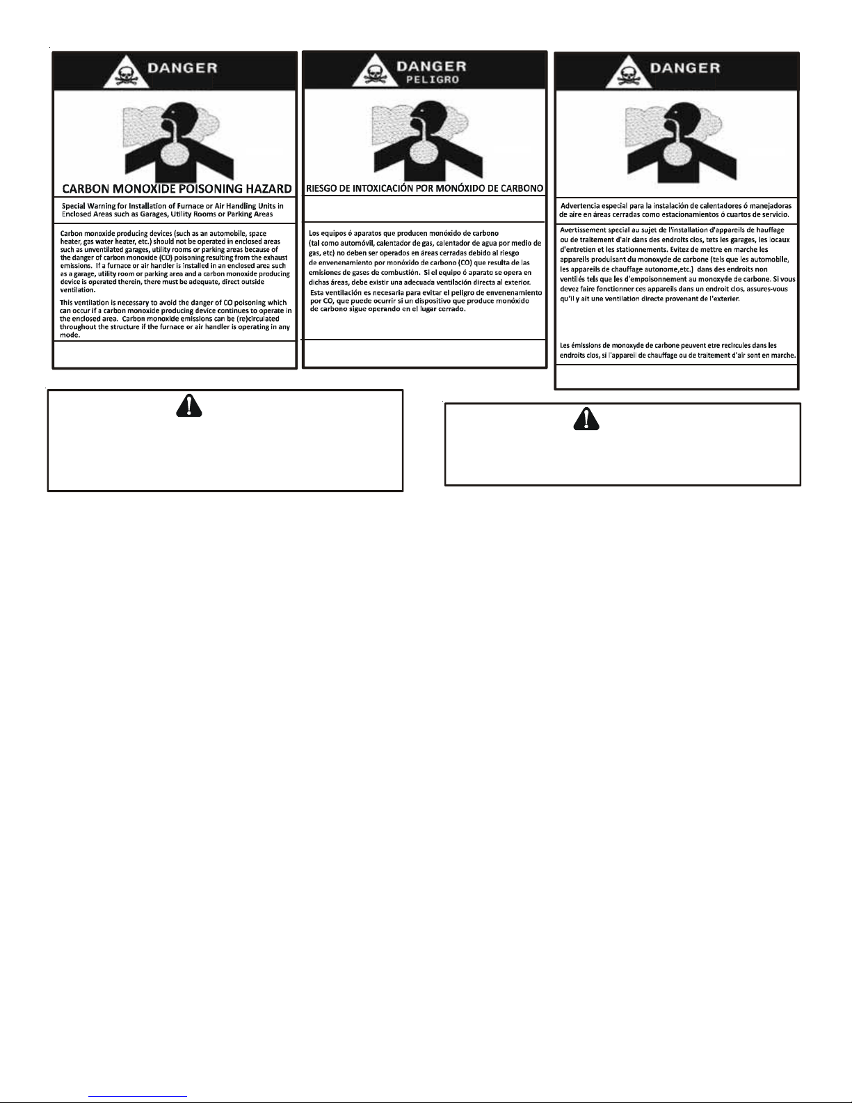
Advertencia especial para la instalación de calentadores ó manejadoras
de aire en áreas cerradas como estacionamientos ó cuartos de servicio.
RISQUE D'EMPOISONNEMENT AU
MONOXYDE DE CARBONE
Cette ventilation est nécessaire pour éviter le danger d'intoxication
au CO pouvant survenir si un appareil produi sant du monoxyde
de carbone continue de fonctionner a u sein de la zone confinée.
Le monoxyde de
des
dommages perm a n e n ts au cerveau et meme la mo rt.
carbone peut ca user des maladies graves telles que
B10259-216
CO can cause serious illness including permanent brain
damage or death.
B10259-216
Las emisiones de monóxido de carbono pueden circular a través
del aparato cuando s e opera en cualquier modo.
El monóxido d e carbono puede causar e nfermedades severas
como daño cerebral permanente ó muerte.
B10259-216
WARNING
WARNING
P
OSSIBLE PROPERTY DAMAGE, PERSONAL INJURY OR DEATH DUE TO
FIRE, EXPLOSION, SMOKE, SOOT, CONDENSATION, ELECTRICAL SHOCK
OR CARBON MONOXIDE MAY RESULT FROM IMPROPER INSTALLATION
REPAIR OPERATION, OR MAINTENANCE OF THIS PRODUCT
.
S
,
HOULD OVERHEATING OCCUR OR THE GAS SUPPLY FAIL TO SHUT OFF
TURN OFF THE MANUAL GAS SHUTOFF VALVE EXTERNAL TO THE
FURNACE BEFORE TURNING OFF THE ELECTRICAL SUPPLY
.
,
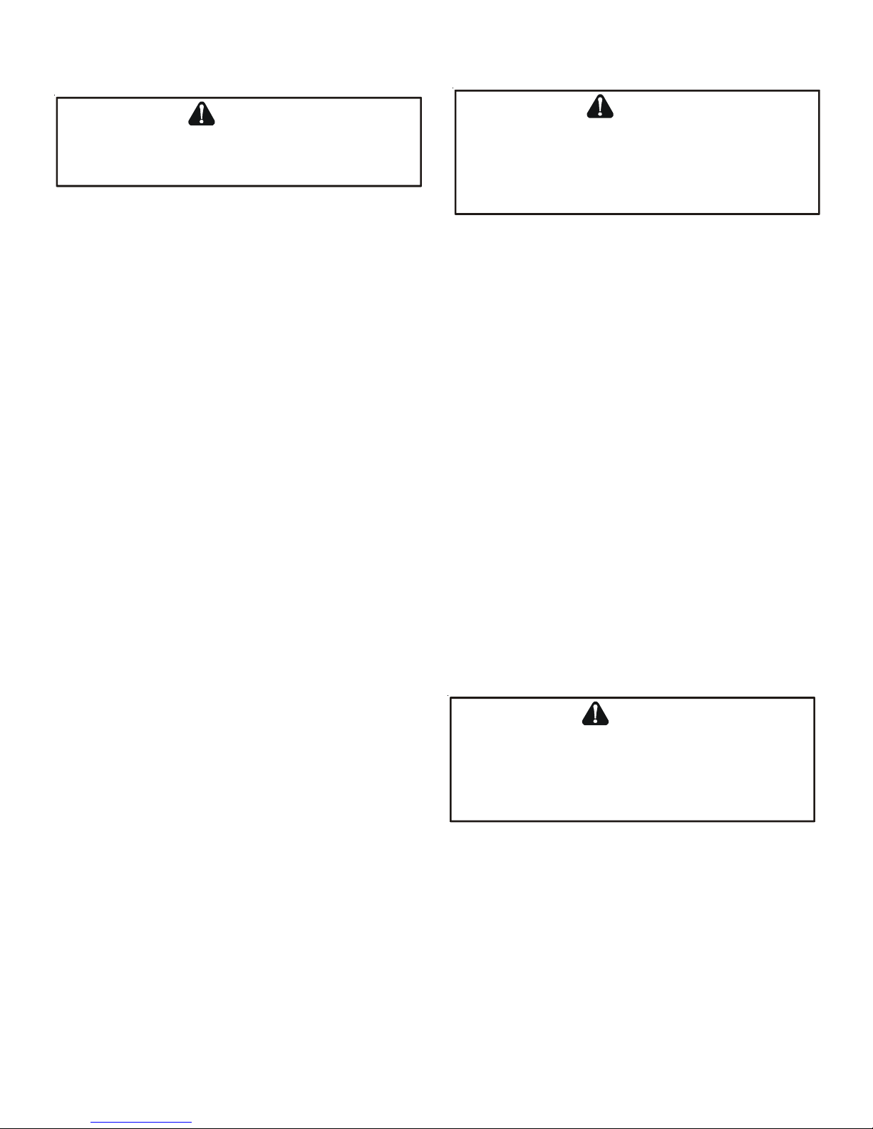
Drain trap must be primed at time of installation. Trap is internally partitioned; add water to both inlet ports until water
appears at both sides of the outlet opening. Failure to prime trap at time of installation may have a negative effect on
combustion quality and pressure switch action.
SHIPPING INSPECTION
All units are securely packed in shipping containers tested according to International Safe Transit Association specifications. The
carton must be checked upon arrival for external damage. If damage is found, a request for inspection by carrier’s agent must be
made in writing immediately .
The furnace must be carefully inspected on arrival for damage and bolts or screws which may have come loose in transit. In the event
of damage the consignee should:
1. Make a notation on delivery receipt of any visible damage to shipment or container .
2. Notify carrier promptly and request an inspection.
3. With concealed damage, carrier must be notified as soon as possible - preferably within five days.
4. File the claim with the following support documents within a nine month statute of limitations.
• Original or certified copy of the Bill of Lading, or indemnity bond.
• Original paid freight bill or indemnity in lieu thereof.
• Original or certified copy of the invoice, showing trade and other discounts or reductions.
• Copy of the inspection report issued by carrier’s representative at the time damage is reported to carrier.
The carrier is responsible for making prompt inspection of damage and for a thorough investigation of each claim. The distributor
or manufacturer will not accept claims from dealers for transportation damage.
ELECTROSTATIC DISCHARGE (ESD) PRECAUTIONS
NOTE: Discharge your body’s static electricity before touching unit. An electrostatic discharge can adversely affect electrical
components.
Use the following precautions during furnace installation and servicing to protect the integrated control module from damage. By
putting the furnace, the control, and the person at the same electrostatic potential, these steps will help avoid exposing the
integrated control module to electrostatic discharge. This procedure is applicable to both installed and non-installed (ungrounded)
furnaces.
4
Page 5
1. Disconnect all power to the furnace. Do not touch the integrated control module or any wire connected to the control prior to
discharging your body’s electrostatic charge to ground.
2. Firmly touch a clean, unpainted, metal surface of the furnaces near the control. Any tools held in a person’s hand during
grounding will be discharged.
3. Service integrated control module or connecting wiring following the discharge process in step 2. Use caution not to recharge
your body with static electricity; (i.e., do not move or shuffle your feet, do not touch ungrounded objects, etc.). If you come
in contact with an ungrounded object, repeat step 2 before
touching control or wires.
4. Discharge your body to ground before removing a new control
from its container. Follow steps 1 through 3 if installing the
control on a furnace. Return any old or new controls to their
containers before touching any ungrounded object.
TO
PREVENT PROPERTY DAMAGE, PERSONAL INJURY OR DEATH DUE TO
FIRE, DO NOT INSTALL THIS FURNACE IN A MOBILE HOME, TRAILER, OR
RECREATIONAL VEHICLE
WARNING
.
TO THE INSTALLER
Before installing this unit, please read this manual thoroughly to familiarize yourself with specific items which must be adhered to,
including but not limited to: unit maximum external static pressure, gas pressures, BTU input rating, proper electrical connections,
circulating air temperature rise, minimum or maximum CFM, and motor speed connections.
P
RODUCT DESCRIPTION
FEATURES
This furnace is a part of the ComfortNet™ family of products. The CTK0* ComfortNet thermostat kit allows this furnace to be installed
as part of a digitally communicating system. The ComfortNet system provides automatic airflow configuration, enhanced setup
features, and enhanced diagnostics. It also reduces the number of thermostat wires to a maximum of four . It may be also installed as
part of a non-communicating system using a standard 24 VAC thermostat.
This product may be installed with the ComfortNet thermostat and a non-ComfortNet compatible single stage air conditioning unit.
However , this reduces the benefits of the ComfortNet system as the enhancements will only apply to the furnace.
P
RODUCT APPLICA TION
This furnace is primarily designed for residential home-heating applications. It is NOT designed or certified for use in mobile homes,
trailers or recreational vehicles. Neither is it designed or certified for outdoor applications. The furnace must be installed indoors
(i.e., attic space, crawl space, or garage area provided the garage area is enclosed with an operating door).
This furnace can be used in the following non-industrial commercial applications:
Schools, Office buildings, Churches, Retail stores,
Nursing homes, Hotels/motels, Common or office areas
In such applications, the furnace must be installed with the following stipulations:
• It must be installed per the installation instructions provided and per local and national codes.
• It must be installed indoors in a building constructed on site.
• It must be part of a ducted system and not used in a free air delivery application.
• It must not be used as a “make-up” air unit.
• It must be installed as a two-pipe systems for combustion air .
• All other warranty exclusions and restrictions apply This furnace is an ETL dual-certified appliance and is appropriate for use
with natural or propane gas (NOTE: If using propane, a propane conversion kit is required).
Dual certification means that the combustion air inlet pipe is optional and the furnace can be vented as a:
Non-direct vent (single pipe) central forced air furnace in which combustion air is taken from the installation area or from air
ducted from the outside or ,
Direct vent (dual pipe) central forced air furnace in which all combustion air supplied directly to the furnace burners through
a special air intake system outlined in these instructions.
This furnace may be used as a construction site heater ONL Y if all of the following conditions are met:
• The vent system is permanently installed per these installation instructions.
• A room thermostat is used to control the furnace. Fixed jumpers that provide continuous heating CANNOT be used and can
cause long term equipment damage.
• Return air ducts are provided and sealed to the furnace.
5
Page 6
• A return air temperature range between 60ºF (16ºC) and 80ºF (27ºC) is maintained.
• Air filters are installed in the system and maintained during construction replaced as appropriate during construction, and
upon completion of construction.
• The input rate and temperature rise are set per the furnace rating plate.
• 100% outside air is provided for combustion air requirements during construction. T emporary ducting can be used.
NOTE: Do not connect the temporary duct directly to the furnace. The duct must be sized for adequate combustion and
ventilation in accordance with the latest edition of the National Fuel Gas Code NFP A 54/ANSI Z223.1 or CAN/CSA B149.1
Installation Codes.
• The furnace heat exchanger , components, duct system, air filters and evaporator coils are thoroughly cleaned following final
construction clean up.
• All furnace operating conditions (including ignition, input rate, temperature rise and venting) are verified according to
these installation instructions.
NOTE: The Commonwealth of Massachusetts requires that the following additional requirements must also be met:
• Gas furnaces must be installed by a licensed plumber or gas fitter .
• A T-handle gas cock must be used.
• If the unit is to be installed in an attic, the passageway to and the service area around the unit must have flooring.
To ensure proper furnace operation, install, operate and maintain the furnace in accordance with these installation and
operation instructions, all local building codes and ordinances. In their absence, follow the latest edition of the National Fuel Gas
Code (NFP A 54/ANSI Z223.1), and/or CAN/CSA B149 Installation Codes, local plumbing or waste water codes, and other applicable
codes.
A copy of the National Fuel Gas Code (NFPA 54/ANSI Z223.1) can be obtained from any of the following:
American National Standards Institute
25 West 43rd Street, 4th Floor
New York, NY 10036
National Fire Protection Association
1 Batterymarch Park
Quincy , MA 012169-7471
CSA International
8501 East Pleasant V alley
Independence, OH 44131
The rated heating capacity of the furnace should be greater than or equal to the total heat loss of the area to be heated. The total
heat loss should be calculated by an approved method or in accordance with “ASHRAE Guide” or “Manual J-Load Calculations”
published by the Air Conditioning Contractors of America.
A copy of the CAN/CSA B149 Installation Codes can also be obtained from:
CSA International
178 Rexdale Boulevard
Etobicoke, Ontario, Canada M9W 1R3
L
OCATION REQUIREMENTS
& C
ONSIDERA TIONS
Follow the instructions listed below and the guidelines provided in
the Combustion and Ventilation Air Requirements section when
selecting a furnace location.
• Centrally locate the furnace with respect to the proposed or
existing air distribution system.
• Ensure the temperature of the return air entering the furnace
TO
PREVENT POSSIBLE EQUIPMENT DAMAGE, PROPERTY DAMAGE
PERSONAL INJURY OR DEATH, THE FOLLOWING BULLET POINTS MUST BE
OBSERVED WHEN INSTALLING THIS UNIT
WARNING
,
.
is between 55°F and 100°F when the furnace is heating.
• Provide provisions for venting combustion products outdoors
through a proper venting system. Special consideration
should be given to vent/flue pipe routing and combustion
air intake pipe when applicable. Refer to Vent/Flue Pipe
and Combustion Air Pipe -Termination Locations for
P
OSSIBLE PROPERTY DAMAGE, PERSONAL INJURY OR DEATH DUE TO
FIRE, EXPLOSION, SMOKE, SOOT, CONDENSATION, ELECTRICAL SHOCK
OR CARBON MONOXIDE MAY RESULT FROM IMPROPER INSTALLATION
REPAIR OPERATION, OR MAINTENANCE OF THIS PRODUCT
WARNING
,
.
appropriate termination locations and to determine if the
piping system from furnace to termination can be
6
Page 7

accomplished within the guidelines given. NOTE: The length of flue and/or combustion air piping can be a limiting factor
in the location of the furnace.
• Locate the furnace so condensate flows downwards to the drain. Do not locate the furnace or its condensate drainage
system in any area subject to below freezing temperatures without proper freeze protection. Refer to Condensate Drain
Lines and T rap for further details.
• Ensure adequate combustion air is available for the furnace. Improper or insufficient combustion air can expose building
occupants to gas combustion products that could include carbon monoxide. Refer to Combustion and Ventilation Air
Requirements.
• Set the furnace on a level floor to enable proper condensate drainage. If the floor becomes wet or damp at times, place the
furnace above the floor on a concrete base sized approximately 1-1/2" larger than the base of the furnace. Refer to the
Horizontal Applications and Considerations for leveling of horizontal furnaces.
• Ensure upflow or horizontal furnaces are not installed directly on carpeting, or any other combustible material. The only
combustible material allowed is wood.
• A special accessory subbase must be used for upright counterflow unit installations over any combustible material (including
wood). Refer to subbase instructions for installation details. (NOTE: A subbase will not be required if an air conditioning coil
is located beneath the furnace between the supply air opening and the combustible floor .
• Exposure to contaminated combustion air will result in safety and performance-related problems. Do not install the furnace
where the combustion air is exposed to the following substances:
permanent wave solutions cleaning solutions (such as perchloroethylene)
printing inks chlorinated waxes or cleaners
paint removers chlorine-based swimming pool chemicals
varnishes water softening chemicals
hydrochloric acid carbon tetrachloride
cements and glues deicing salts or chemicals
halogen type refrigerants antistatic fabric softeners for clothes dryers
and masonry acid washing materials
• Seal off a non-direct vent furnace if it is installed near an area frequently contaminated by any of the above substances. This
protects the non-direct vent furnace from airborne contaminants. T o ensure that the enclosed non-direct vent furnace has
an adequate supply of combustion air , vent from a nearby uncontaminated room or from outdoors. Refer to the Combustion
and Ventilation Air Requirements for details.
• If the furnace is used in connection with a cooling coil unit, install the furnace upstream or in parallel with the cooling coil
unit. Premature heat exchanger failure will result if the cooling unit is placed ahead of the furnace.
For vertical (upflow or downflow) applications, the minimum cooling coil width shall not be less than furnace width
minus 1”. Additionally, a coil installed above an upflow furnace or under a counterflow furnace may be the same
width as the furnace or may be one size larger than the furnace. Example: a “C” width coil may be installed with
a “B” width furnace.
For upflow applications, the front of the coil and furnace must face the same direction.
• If the furnace is installed in a residential garage, position the furnace so that the burners and ignition source are located not
less than 18 inches (457 mm) above the floor. Protect the furnace from physical damage by vehicles.
• If the furnace is installed horizontally, ensure the access doors are not on the “up/top” or “down/bottom” side of the
furnace.
• Do not connect this furnace to a chimney flue that serves a separate appliance designed to burn solid fuel.
• On Counterflow Installations, the air conditioning coil must be downstream on the supply (positive) side of the
furnace heat exchanger .
• Counterflow Installation over a noncombustible floor. Before setting the furnace over the plenum opening, ensure
the surface around the opening is smooth and level. A tight seal should be made between the furnace base and floor
by using a silicone rubber caulking compound or cement grout.
7
Page 8
b
ible fl
• Counterflow Installation over a combustible
floor. If installation over a combustible floor
becomes necessary, use an accessory subbase
(see Specification Sheet applicable for your
model for details.) A special accessory subbase
must be used for upright counterflow unit
installations over any combustible material
including wood. Refer to subbase instructions
for installation details. Follow the instructions
POSITION* SIDES REAR FRONT BOTTOM FLUE TOP
Upflow 0" 0" 3" C 0" 1"
Horizontal 6" 0" 3" C 0" 6"
C = If placed on combustible floo r, floor MUS T b e w oo d on ly.
with the subbase for proper installation. Do not
install the furnace directly on carpeting, tile,
or other combustible material other than wood
flooring. (NOTE: The subbase will not be
required if an air conditioning coil is installed
between the supply air opening on the furnace
and the floor .)
CLEARANCES AND ACCESSIBILITY
NOTES:
• For servicing or cleaning, a 24” front clearance is
required.
• Unit connections (electrical, flue and drain) may necessitate
greater clearances than the minimum clearances listed above.
• In all cases, accessibility clearance must take precedence over
clearances from the enclosure where accessibility clearances are
greater.
NOTES:
• For servicing or cleaning, a 24” front clearance is required.
• Unit connections (electrical, flue and drain) may necessitate
greater clearances than the minimum clearances listed above.
• In all cases, accessibility clearance must take precedence over
clearances from the enclosure where accessibility clearances are
greater.
POSITION* SIDES REAR FRONT BOTTOM FLUE TOP
Counterfl ow 0" 0" 3" NC 0" 1"
Horizontal 6" 0" 3" C 0" 6"
C = If placed on combustible floor, floor MUS T b e w oo d on ly.
NC = For install ation on non-combustible fl oors only. A combustible subbase
must
*M96VC MINIMUM CLEARANCES TO COMBUSTIBLE MATERIALS
(INCHES)
*C96VC MINIMUM CLEARANCES TO COM BUSTIBLE MATERIALS
(INCHES)
e used for inst allations on combust
TOP
BOTTOM
Counterflow
ooring.
TOP
BOTTOM
Figure 1
Installations must adhere to the clearances to combustible materials to which this furnace has been design certified. The minimum
clearance information for this furnace is provided on the unit’s clearance label. These clearances must be permanently maintained.
Clearances must also accommodate an installation’s gas, electrical, and drain trap and drain line connections. If the alternate
combustion air intake or vent/flue connections are used additional clearance must be provided to accommodate these connections.
Refer to V ent/Flue Pipe and Combustion Air Pipe for details.
NOTE: In addition to the required clearances to combustible materials, a minimum of 24 inches service clearance must be available
in front of the unit.
A furnace installed in a confined space (i.e., a closet or utility room) must have two ventilation openings with a total minimum free
area of 0.25 square inches per 1,000 BTU/hr of furnace input rating. Refer to Specification Sheet applicable to your model for
minimum clearances to combustible surfaces. One of the ventilation openings must be within 12 inches of the top; the other opening
must be within 12 inches of the bottom of the confined space. In a typical construction, the clearance between the door and door
frame is usually adequate to satisfy this ventilation requirement.
EXISTING FURNACE REMOVAL
NOTE: When an existing furnace is removed from a venting system serving other appliances, the venting system may be too large to
properly vent the remaining attached appliances.
The following vent testing procedure is reproduced from the American National Standard/National Standard of Canada for Gas-
Fired Central Furnaces ANSI Z21.47, CSA-2.3 latest edition Section 1.23.1.
The following steps shall be followed with each appliance connected to the venting system placed in operation, while any other
appliances connected to the venting system are not in operation:
8
Page 9
1. Seal any unused openings in the venting system.
2. Inspect the venting system for proper size and horizontal pitch, as required by the National Fuel Gas Code, ANSI
Z223.1 or the Natural Gas and Propane Installation Code, CSA B149.1-05 and these instructions. Determine that there
is no blockage or restriction, leakage, corrosion and other deficiencies which could cause an unsafe condition.
3. As far as practical, close all building doors and windows and all doors between the space in which the appliance(s)
connected to the venting system are located and other spaces of the building.
4. Close fireplace dampers.
5. T urn on clothes dryers and any appliance not connected to the venting system. Turn on any exhaust fans, such as range
hoods and bathroom exhausts, so they shall operate at maximum speed. Do not operate a summer exhaust fan.
6. Follow the lighting instructions. Place the appliance being inspected in operation. Adjust thermostat so appliance shall
operate continuously .
7. T est for spillage from draft hood appliances at the draft hood relief opening after 5 minutes of main burner operation.
Use the flame of a match or candle.
8. If improper venting is observed during any of the above tests, the venting system must be corrected in accordance
with the National Fuel Gas Code ANSI Z223.1/NFPA 54 and/or National Gas and Propane Installation Code CSA B149.1-05.
9. After it has been determined that each appliance connected to the venting system properly vents when tested as
outlined above, return doors, windows, exhaust fans, fireplace dampers and any other gas burning appliance to their
previous conditions of use.
If resizing is required on any portion of the venting system, use the appropriate table in Appendix G in the latest edition of the
National Fuel Gas Code ANSI Z223.1 and/or CSA B149.1-05 Installation Codes.
THERMOSTAT LOCATION
The thermostat should be placed approximately five feet from the floor on a vibration-free, inside wall in an area having good air
circulation. Do not install the thermostat where it may be influenced by any of the following:
• Drafts, or dead spots behind doors, in corners, or under cabinets.
• Hot or cold air from registers.
• Radiant heat from the sun.
• Light fixtures or other appliances.
TO
• Radiant heat from a fireplace.
• Concealed hot or cold water pipes, or chimneys.
• Unconditioned areas behind the thermostat, such as an
outside wall.
AVOID PROPERTY DAMAGE, PERSONAL INJURY OR DEATH
SUFFICIENT FRESH AIR FOR PROPER COMBUSTION AND VENTILATION OF
FLUE GASES MUST BE SUPPLIED
SUPPLIED INTO THE FURNACE AREA
Consult the instructions packaged with the thermostat for mounting instructions and further precautions.
C
OMBUSTION
& V
ENTILA TION AIR REQUIREMENTS
Improved construction and additional insulation in buildings have reduced heat loss by reducing air infiltration and escape around
doors and windows. These changes have helped in reducing heating/cooling costs but have created a problem supplying combustion and ventilation air for gas fired and other fuel burning appliances. Appliances that pull air out of the house (clothes dryers,
exhaust fans, fireplaces, etc.) increase the problem by starving appliances for air .
House depressurization can cause back drafting or improper combustion of gas-fired appliances, thereby exposing building
occupants to gas combustion products that could include carbon monoxide.
WARNING
,
. M
OST HOMES REQUIRE OUTSIDE AIR BE
.
If this furnace is to be installed in the same space with other gas appliances, such as a water heater , ensure there is an adequate
supply of combustion and ventilation air for the other appliances. Refer to the latest edition of the National Fuel Gas Code NFPA
54/ANSI Z223.1 or CAN/CSA B149 Installation Codes or applicable provisions of the local building codes for determining the
combustion air requirements for the appliances.
Most homes will require outside air be supplied to the furnace area by means of ventilation grilles or ducts connecting directly to
the outdoors or spaces open to the outdoors such as attics or crawl spaces.
9
Page 10
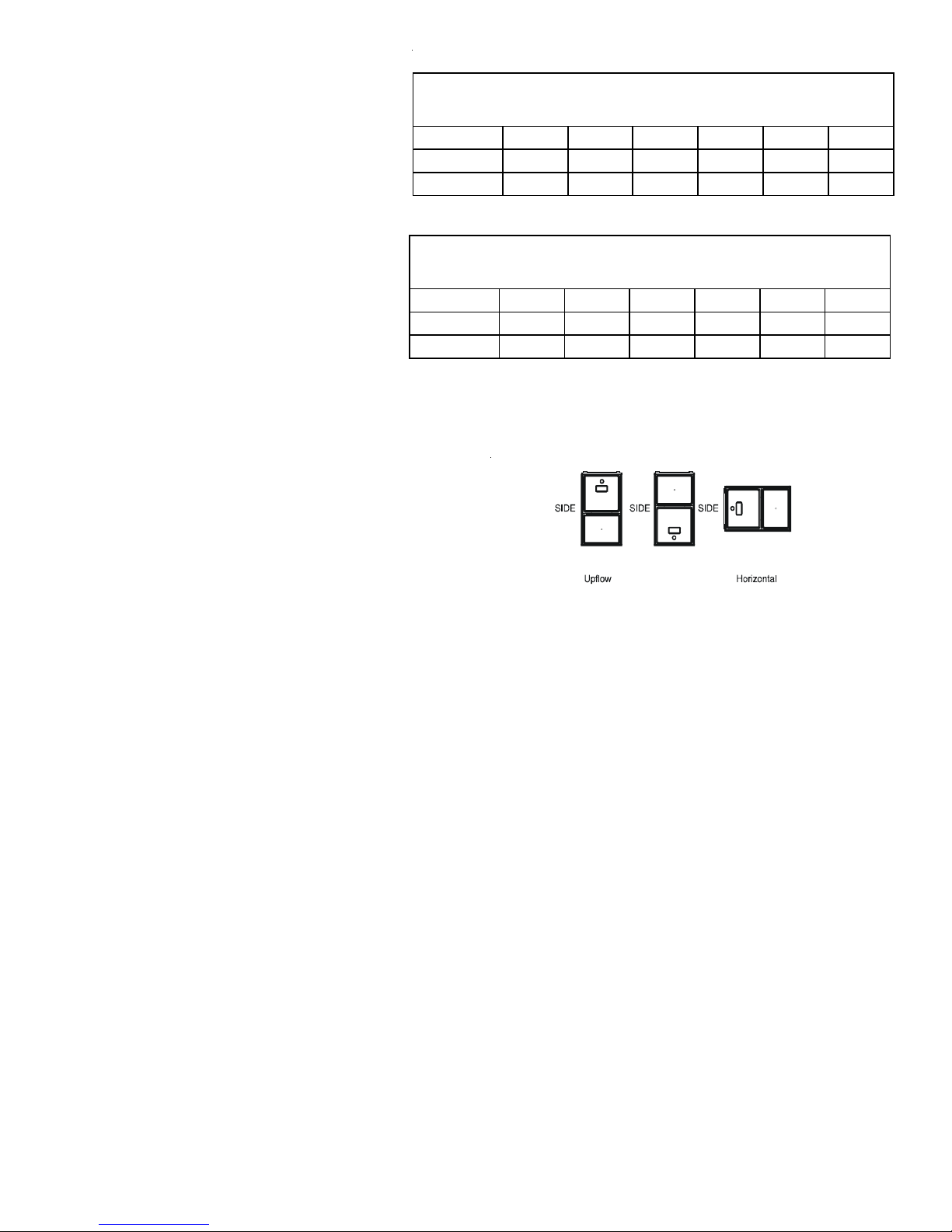
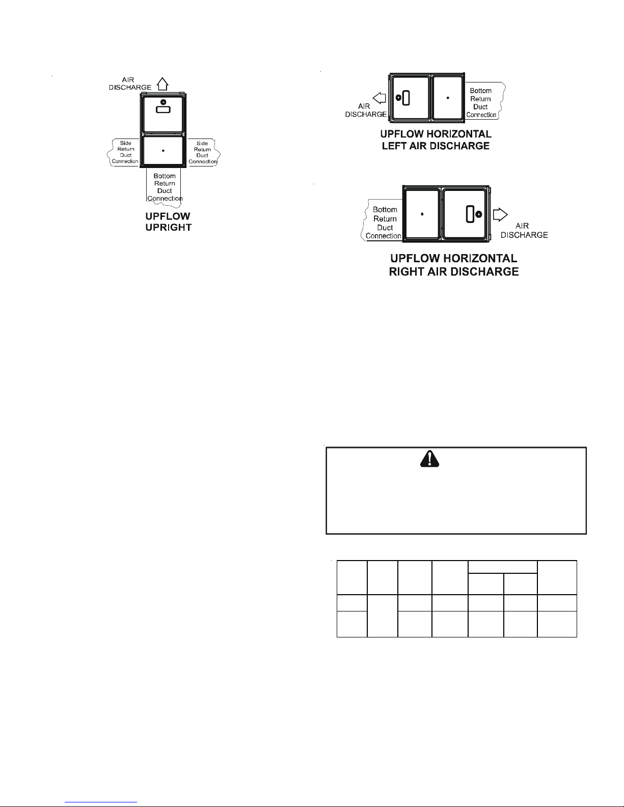
I
NST ALLATION POSITIONS
This furnace may be installed in an upright position or horizontal on either the left or right side panel. Do not install this furnace
on its back. For upright upflow furnaces, return air ductwork may be attached to the side panel(s) and/or basepan. For horizontal
upflow furnaces, return air ductwork must be attached to the basepan. For both upright or horizontal counterflow furnaces, return
ductwork must be attached to the basepan (top end of the blower compartment). NOTE: Ductwork must never be attached to the
back of the furnace. Contact your distributor for proper airflow requirements and number of required ductwork connections. Refer
to “Recommended Installation P ositions” figure for appropriate installation positions, ductwork connections, and resulting airflow
arrangements.
H
ORIZONT AL APPLICA TIONS
& C
ONSIDERA TIONS
When installing a furnace horizontally, additional consideration must be given to the following:
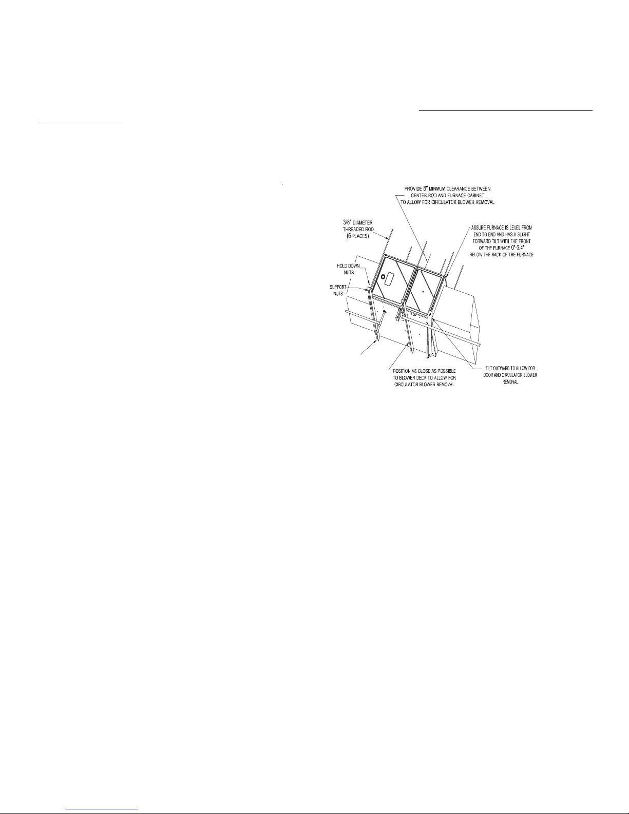
FURNACE SUSPENSION
If suspending the furnace from rafters or joists, use 3/
8" threaded rod and 2”x2”x1/8” angle iron as shown in
the following diagram. The length of rod will depend on
the application and the clearances necessary .
If the furnace is installed in a crawl space it must be
suspended from the floor joist or supported by a concrete pad. Never install the furnace on the ground or
allow it to be exposed to water .
2" 2" 3/8"
ANGLE IRON
XX
(3
PLACES
FRONT COVER PRESSURE SWITCH TUBE LOCATION
When an upflow model is installed horizontally with
left side down or a counterflow model is installed
)
Figur e 2
horizontally with right side down, the front cover
pressure switch tube must be re-located to the lower port of the collector box cover .
1. R emove tube from front cover pressure switch and collector box cover.
2. R emove rubber plug from bottom collector box port and install on top collector box port.
3. Locate 24” x 1/4” tube in parts bag.
4. Install one end on front cover pressure switch.
5. R oute tube to lower port on collector box cover and cut off excess tubing.
DRAIN TRAP AND LINES
In horizontal applications the condensate drain trap is secured to the furnace side panel, suspending it below the furnace. A minimum
clearance of 5 ½” below the furnace must be provided for the drain trap. Additionally , the appropriate downward piping slope must
be maintained from the drain trap to the drain location. Refer to Condensate Drain T rap and Lines for further details. If the drain trap
and drain line will be exposed to temperatures near or below freezing, adequate measures must be taken to prevent condensate from
freezing.
LEVELING
Leveling ensures proper condensate drainage from the heat exchanger and induced draft blower . For proper flue pipe drainage, the
furnace must be level lengthwise from end to end. The furnace should have a slight tilt from back to front with the access doors
downhill from the back panel approximately 1/2 to 3/4 inches. The slight tilt allows the heat exchanger condensate, generated in
the recuperator coil, to flow forward to the recuperator coil front cover .
ALTERNATE VENT/FLUE AND COMBUSTION AIR CONNECTIONS
In horizontal installations provisions for alternate flue and combustion air piping are available for upflow furnaces with left discharge
and counterflow furnaces with right air discharge. This configuration allows the flue and combustion air piping to be run vertically
through the side of the furnace. Refer to the “R ecommended Installation Positions” figure for further detail. The standard piping
connections may also be used in these positions. Refer to Vent/Flue Pipe and Combustion Air Pipe for details concerning the
conversion to the alternate vent/flue and combustion air connections.
10
Page 11
When using the horizontal alternate vent configuration, you must use the RF000142 vent drain kit. See following illustration.
Figure 3B
Alternate Vent/Flue Location
Figure 3A
ALTERNATE ELECTRICAL AND GAS LINE CONNECTIONS
Recommende d Installation Positions
Figure 3C
This furnace has provisions allowing for electrical and gas line
connections through either side panel. In horizontal applications the connections can be made either through the “top” or “bottom”
of the furnace.
DRAIN P AN
A drain pan must be provided if the furnace is installed above a conditioned area. The drain pan must cover the entire area under the
furnace (and air conditioning coil if applicable).
FREEZE PROTECTION
Refer to Horizontal Applications and Conditions - Drain T rap and Lines.
P
ROP ANE GAS/HIGH ALTITUDE INST ALLATIONS
WARNING
This furnace is shipped from the factory configured for natural gas
at standard altitude. Propane gas installations require an orifice
and orifice change to compensate for the energy content difference between natural and propane gas.
High altitude installations may require both a pressure switch and
an orifice/spring change. These changes are necessary to compensate for the natural reduction in the density of both the gas fuel
and the combustion air at higher altitude.
For installations above 7000 feet, please refer to the furnace Specification Sheets for required kit(s).
Contact the distributor for a tabular listing of appropriate
manufacturer’s kits for propane gas and/or high altitude installations. The indicated kits must be used to insure safe and proper
furnace operation. All conversions must be performed by a qualified
installer , or service agency .
P
OSSIBLE PROPERTY DAMAGE, PERSONAL INJURY OR DEATH MAY
OCCUR IF THE CORRECT CONVERSION KITS ARE NOT INSTALLED
APPROPRIATE KITS MUST BE APPLIED TO ENSURE SAFE AND PROPER
FURNACE OPERATION
QUALIFIED INSTALLER OR SERVICE AGENCY
Gas Altitude Kit Orifice
Natural None #45 3.5" w. c. 1.9" w.c. None
Propane
1
LPM-08* supp orts both Honeywell and W h ite-Rodgers 2-stage valves
NOTE: In Canada , gas furnaces are only certified to 4500 feet.
0-7000
. ALL
CONVERSIONS MUST BE PERFORMED BY A
.
Manifold Pressure
LP M -08*
1
High
Stage
1.25mm 1 0. 0" w.c. 6.0" w.c. None
Low
Stage
. THE
Pressure
Switch
Change
11
Page 12
V
ENT/FLUE PIPE
& C
OMBUSTION AIR PIPE
WARNING
F
AILURE TO FOLLOW THESE INSTRUCTIONS CAN RESULT IN BODILY
INJURY OR DEATH
GIVEN IN THIS SECTION
. C
AREFULLY READ AND FOLLOW ALL INSTRUCTIONS
.
U
PON COMPLETION OF THE FURNACE INSTALLATION, CAREFULLY
INSPECT THE ENTIRE FLUE SYSTEM BOTH INSIDE AND OUTSIDE OF THE
FURNACE TO ASSURE IT IS PROPERL Y SEALED
SYSTEM CAN RESULT IN SERIOUS PERSONAL INJURY OR DEATH DUE TO
EXPOSURE TO FLUE PRODUCTS, INCLUDING CARBON MONOXIDE
WARNING
. L
EAKS IN THE FLUE
.
A condensing gas furnace achieves its high level of efficiency by extracting almost all of the heat from the products of combustion
and cooling them to the point where condensation takes place. Because of the relatively low flue gas temperature and water
condensation requirements, PVC pipe is used as venting material.
In addition to PVC and ABS pipe and fittings, Innoflue® by Centrotherm Eco Systems and PolyP ro® by M&G Duravent are also
approved vent and combustion air materials for installations in the U.S.A. and Canada. Manufacturers Installation instructions for these products must be followed. These products have specific instructions for installing, joining and terminating.
Do not mix materials or components of one manufacturer with materials or components of another manufacturer.
All furnaces are built with 2" vent / intake pipe and connectors. For furnaces requiring installation of 3" pipe, the transition
from 2" to 3" should be done as close to the furnace as practically possible.
This furnace must not be connected to T ype B, BW , or L vent or vent connector, and must not be vented into any portion of a factory
built or masonry chimney except when used as a pathway for PVC as described later in this section. Never common vent this
appliance with another appliance or use a vent which is used by a solid fuel appliance. Do not use commercially available “no hub
connectors” other than those shipped with this product.
It is the responsibility of the installer to follow the manufacturers’ recommendations and to verify that all vent/flue piping and
connectors are compatible with furnace flue products. Additionally, it is the responsibility of the installer to ensure that all piping and
connections possess adequate structural integrity and support to prevent flue pipe separation, shifting, or sagging during furnace
operation.
DUAL CERTIFICATION: NON-DIRECT/DIRECT VENT
This furnace is dual certified and may be installed as a non-direct vent (single pipe) or direct vent (dual pipe) appliance. A non-direct
vent installation requires only a vent/flue pipe, while a direct vent installation requires both a vent/flue pipe and a combustion air
intake pipe. Refer to the appropriate section for details concerning piping size, length, number of elbows, furnace connections, and
terminations.
MATERIALS AND JOINING METHODS
Two-three-inch nominal diameter PVC Schedule 40 pipe meeting ASTM D1785, PVC primer meeting ASTM F656, and PVC
solvent cement meeting ASTM D2564 specifications must be
used. Fittings must be DWV type fittings meeting ASTM D2665
and ASTM D3311. Carefully follow the manufacturer ’ s instructions for cutting, cleaning, and solvent cementing of PVC.
TO
AVOID BODILY INJURY, FIRE OR EXPLOSION, SOLVENT CEMENTS
MUST BE KEPT AWAY FROM ALL IGNITION SOURCES (I.E
FLAMES, AND EXCESSIVE HEAT) AS THEY ARE COMBUSTIBLE LIQUIDS
VOID BREATHING CEMENT VAPORS OR CONTACT WITH SKIN AND/OR
A
EYES
.
The use of Schedule 40 PVC or ABS cellular core (Foam Core)
plastic pipe is also acceptable as a flue/vent and intake pipe material. PVC primer meeting ASTM F656 and PVC solvent
cement meeting ASTM D2564 specifications must be used. Fittings must be DWV type fittings meeting ASTM D2665 and
ASTM D3311. Carefully follow the manufactures instructions for cutting, cleaning and solvent cementing of PVC.
For Canadian installations; all PVC pipe, fittings and joining materials must be UL S636 listed.
As an alternative to PVC pipe, primer, solvent cement, and fittings, ABS materials which are in compliance with the following
specifications may be used. Two-or-three-inch ABS Schedule 40 pipe must meet ASTM D1527 and, if used in Canada, must be CSA
listed. Solvent cement for ABS to ABS joints must meet ASTM D2235 and, if used in Canada, must be CSA listed. The solvent cement
for the PVC to ABS transition joint must meet ASTM D3138. Fittings must be DWV type fittings meeting ASTM D2661 and ASTM
D3311 and, if used in Canada, must be CSA listed. Carefully follow the manufacturers’ instructions for cutting, cleaning, and solvent
cementing PVC and/or ABS.
WARNING
.,
SPARKS, OPEN
.
12
Page 13
All 90° elbows must be medium radius (1/4 bend DWV) or long radius (Long sweep 1/4 bend DWV) types conforming to ASTM D3311.
A medium radius (1/4 bend DWV) elbow measures 3 1/16” minimum from the plane of one opening to the center line of the other
opening for 2” diameter pipe, and 4 9/16” minimum for 3” pipe.
PROPER VENT/FLUE AND COMBUSTION AIR PIPING PRACTICES
Adhere to these instructions to ensure safe and proper furnace
performance. The length, diameter , and number of elbows of the
vent/flue pipe and combustion air pipe (when applicable) affects
the performance of the furnace and must be carefully sized. All
piping must be installed in accordance with local codes and these
instructions.
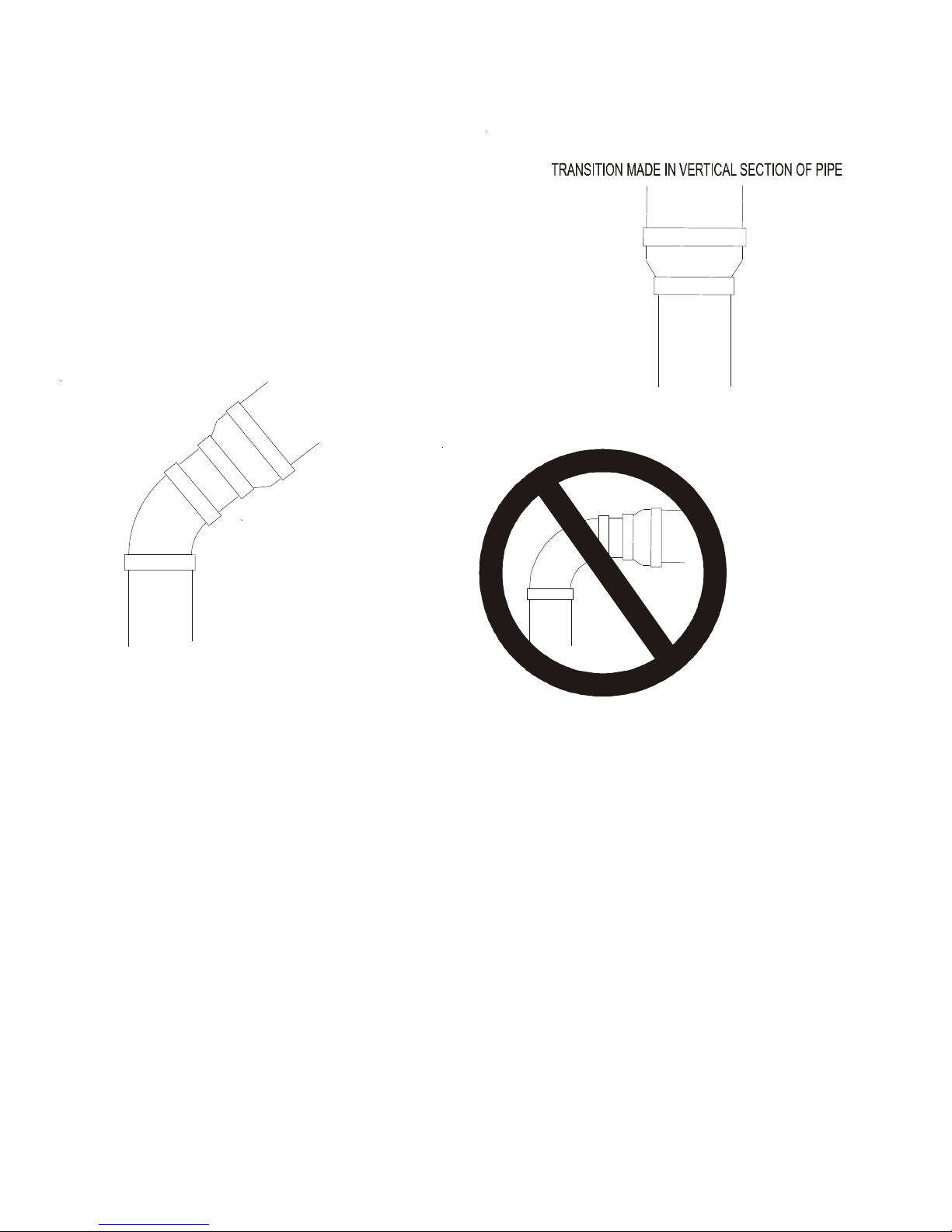
Some models require the use of 3” pipe. Do not transition
from a 2” to 3” pipe in a horizontal section of pipe as this
may create a water trap.
ACCEPTABLE
TRANSITION NO LESS
THAN 45 DEGREES TO
HORIZONTAL PLANE TO
AVOID CREATING A WATER
TRAP IN VENT PIPING.
PREFERRED
Figure 4
NO TRANSITION ON
HORIZONTAL PLANE,
THIS CREATES A
WATER TRAP AND
RESTRICTS FLUE
GASES
Figure 5
Piping must be adequately secured and supported to pro-
Figure 6
hibit sagging, joint separation, and/or detachment from
the furnace. Horizontal runs of vent/flue piping must be
supported every three to five feet and must maintain a 1/4 inch per foot downward slope, back towards the furnace, to properly
return condensate to the furnace’s drain system. Allowances should be made for minor expansion and contraction due to temperature
variations. For this reason, particular care must be taken to secure piping when a long run is followed by a short offset of less than
40 inches.
Precautions should be taken to prevent condensate from freezing inside the vent/flue pipe and/or at the vent/flue pipe termination.
All vent/flue piping exposed to freezing temperatures below 35°F for extended periods of time must be insulated with 1/2” thick
closed cell foam. Also all vent/flue piping exposed outdoors in excess of the terminations shown in this manual (or in unheated areas)
must be insulated with 1/2” thick closed cell foam. Inspect piping for leaks prior to installing insulation.
TERMINATION LOCATIONS
NOTE: Refer to Location Requirements and Considerations for combustion air contaminant restrictions.
The following bullets and diagram describe the restrictions concerning the appropriate location of vent/flue pipe and combustion air
intake pipe (when applicable) terminations. Refer to Non-Direct V ent (Single Pipe) Piping and Direct Vent (Dual Pipe) Piping located
in this section for specific details on termination construction.
• All terminations (flue and/or intake) must be located at least 12 inches above ground level or the anticipated snow level.
• Vent terminations (non-direct and direct vent) must terminate at least 3 feet above any forced air inlet located within 10
feet.
NOTE: This provision does not apply to the combustion air intake termination of a direct vent application.
• The vent termination of a non-direct vent application must terminate at least 4 feet below , 4 feet horizontally from, or 1 foot
above any door, window , or gravity air inlet into any building.
13
Page 14
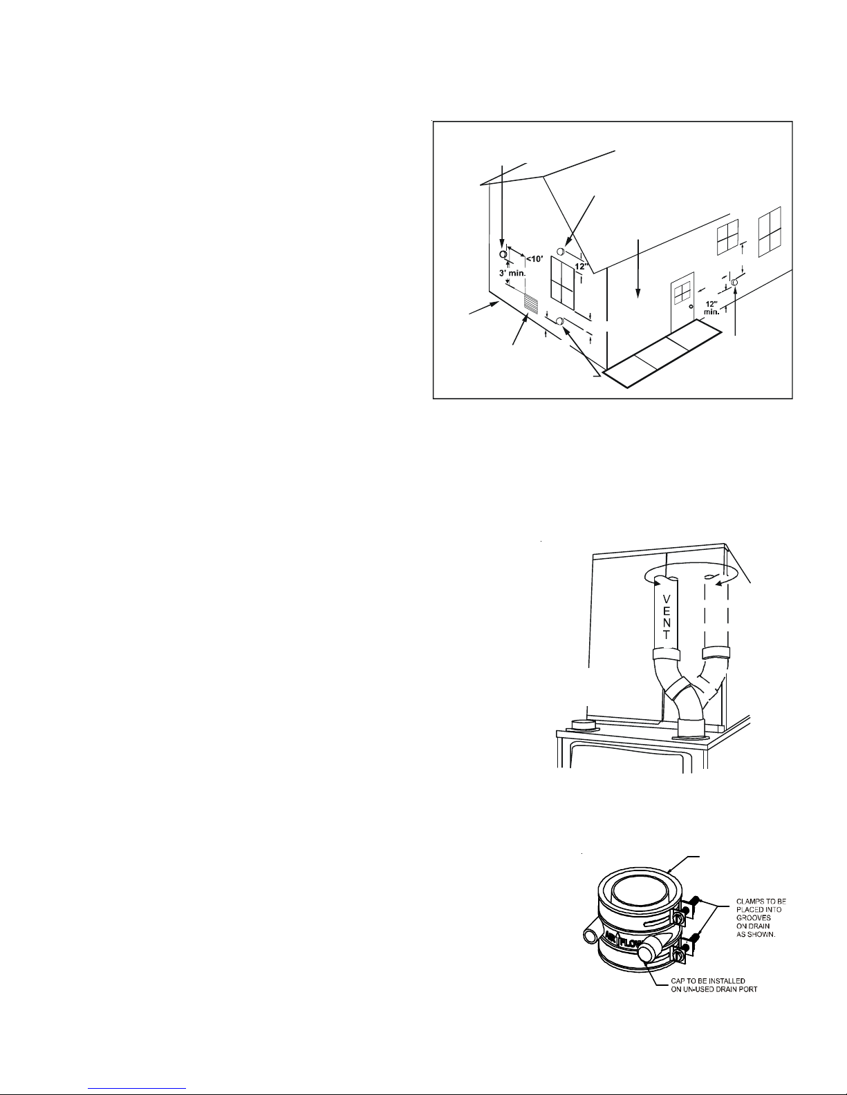
• The vent termination of a direct vent application must terminate at least 12 inches from any opening through which flue
gases may enter a building (door, window, or gravity air inlet).
• The vent termination of vent pipe run vertically through a roof must terminate at least 12 inches above the roof line (or the
anticipated snow level) and be at least 12 inches from any
vertical wall (including any anticipated snow build up).
• A vent termination shall not terminate over public walkways
or over an area where condensate or vapor could create a
nuisance or hazard or could be detrimental to the operation
of regulators, relief valves, or other equipment.
• The combustion air intake termination of a direct vent
application should not terminate in an area which is
Non-Dir ect Vent
&
Direct Vent
Vent/ F lue Terminations
Non-Direc t Vent
Vent/ F lue Termination
No T erminations
Above Walkway
frequently dusty or dirty .
4' min.
4'
NOTE: In Canada, the Canadian Fuel Gas Code takes precedence
over the preceding termination restrictions.
CANADIAN VENTING REQUIREMENTS
In Canada, venting must conform to the requirements of the
current CAN/CSA-B149.1-05 Installation Code. Use only CSA-listed,
ULC-S636 compliant two- or three-inch diameter PVC or ABS pipe,
solvent cement, and fittings throughout. The certified piping
Grade or Highest
Anticipated
Snow Level
Forced Air
Inlet
12" min.
12" min.
Direct Vent
Vent/Flue Termination
Vent Termination Clearances
Figure 7
min.
Non-Direct Vent
Vent/ F lue Termination
should be clearly marked with the ULC Std “S636” on the pipe and
fittings. Carefully follow the pipe manufacturers’ instructions for cutting, cleaning, and solvent cementing PVC and/or ABS.
The vent can be run through an existing unused chimney provided the space between the vent pipe and the chimney is insulated and
closed with a weather-tight, corrosion-resistant flashing.
STANDARD FURNACE CONNECTIONS
It is the responsibility of the installer to ensure that the piping connections to the
furnace are secure, airtight, and adequately supported.
VENT/FLUE PIPE
The vent pipe outlet is sized to accept 2” pipe. Secure vent/flue pipe directly
into the furnace fitting with the appropriate glue. Alternately, a small section
of 2" pipe may be glued in the furnace socket and a rubber coupling installed to
allow removal for future service. Combustion Air and Vent piping should be
routed in a manner to avoid contact with refrigerant lines, metering devices,
condensate drain lines, etc. If necessary, clearances may be increased by
creating an offset using two 45 degree elbows. This joint can be rotated on the
fitting to establish maximum clearance between refrigerant lines, metering
devices, and condensate drain lines, etc. This joint is the equivalent of one 90
deg. elbow when considering elbow count. (See Figure 9A)
NOTE: For non-direct vent installations, a minimum of one 90° elbow should be
installed on the combustion air intake coupling to guard against inadvertent
blockage.
COMBUSTION AIR PIPE
45 DEGREE
LONG-SWEEP
ELBOWS
Increased Clearance Config uration
Figure 9A
VENT-DRAIN
DIRECT VENT INSTALLATIONS
On upflow units secure the combustion air intake pipe to the air intake coupling by using a
take apart rubber coupling supplied with the furnace or a plastic coupling. Also, the
intake coupling may be inverted to allow the intake pipe to be glued directly to it. After
inverting the coupling, secure it to the furnace top with screws. On counterflow units
secure the combustion air intake pipe to the air intake coupling using the rubber coupling and
worm gear hose clamps provided with the unit. The counterflow rubber coupling allows service removal of air intake piping internal to the furnace blower compartment. The combustion air intake pipe can also be secured directly to the counterflow unit air intake pipe coupling.
Figure 9B
14
Page 15
COMBUSTION AIR INT AKE OPTION: The RF000142 coupling can be secured directly to the furnace intake coupling if condensation is a concern. If the RF000142 is used on the combustion air inlet, it must be installed with the arrow pointing up. It
should be noted, the combustion air will actually be moving in a direction opposite of the arrow on the RF000142 coupling. It
must have a field supplied, trapped drain tube free-draining to proper condensate disposal location. A loop in the drain tube
can serve as a trap. The unused RF000142 drain fitting should be capped. (See Figure 9B)
NON-DIRECT VENT INSTALLATIONS
A minimum of one 90° elbow should be installed on the combustion
air intake “coupling” to guard against inadvertent blockage.
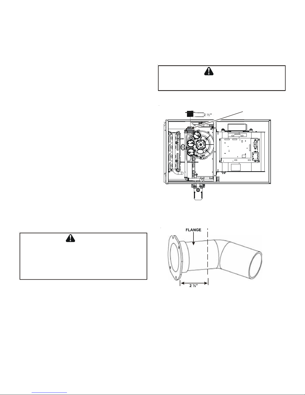
ALTERNATE VENT/FLUE LOCATION
The alternate vent/flue location is the large hole directly in line
with the induced draft blower outlet. T o use the alternate vent/flue
location refer to the following steps and the “Alternate Vent/Flue
Location” figure. To use an alternate vent location on a
counterflow / horizontal model, a special kit is required.
NOTE: In the horizontal left installation position, a means of
condensate collection must be provided to keep vent pipe condensate from entering the draft inducer housing. If the vent
drain elbow is eliminated from the installation, an RF000142
kit must be used.
E
DGES OF SHEET METAL HOLES MAY BE SHARP
PRECAUTION WHEN REMOVING HOLE PLUGS
Inse r t f l an g e. Cut 2 ½” lo n g .
WARNING
. USE
.
GLOVES AS A
RF000142
1. Remove the four screws from the vent pipe flange on top
the furnace.
2. R emove the internal elbow and vent pipe
3. Cut 2 1/2" from the flange .
4. R emove plastic plug in line with the inducer outlet
5. Install cut end of the flanged section and connect to inducer
with rubber coupling supplied with furnace.
Figu re 10
6. Install screws removed in step 1 securing flange to cabinet.
WARNING
THE
RUBBER ELBOW IS NOT DESIGNED TO SUPPORT A LOAD
RUBBER ELBOW IS MOUNTED EXTERNALLY TO THE FURNACE CABINET
EXTREME CARE MUST BE TAKEN TO ADEQUATELY SUPPORT FIELD
SUPPLIED VENT/FLUE PIPING, AS DAMAGE CAN RESULT IN LEAKS
CAUSING BODILY INJURY OR DEATH DUE TO EXPOSURE TO FLUE GASES
INCLUDING CARBON MONOXIDE
ALTERNATE COMBUSTION AIR PROVISION
(Upflow / Horizontal models only)
. W
HEN THE
,
-
,
E
R
E
H
T
U
C
Figure 11
Vent/Flue Pipe Cuts
When using the alternate venting location, either in a horizontal left side down installation or a vertical installation using down – venting, an alternate combustion air opening can be
used. A locating dimple is located on the right side of the furnace cabinet. The locating dimple is 1 7/8" measured from the
front edge of the cabinet in line with the knock out. To use the alternate combustion air location:
1. R emove screws and combustion air flange from cabinet.
2. Insert cabinet plug in unused combustion air hole.
3. Drill a pilot hole at the cabinet dimple (size dictated by knockout tool used).
4. Use a knockout tool to create a 3" diameter hole
5. Install combustion air flange and secure with screws removed in step one.
15
Page 16

NON-DIRECT VENT (SINGLE PIPE) PIPING
Non-direct vent installations require only a vent/flue pipe. The
vent pipe can be run horizontally with an exit through the side of
the building or run vertically with an exit through the roof of the
BE
SURE NOT TO DAMAGE INTERNAL WIRING OR OTHER COMPONENTS
WHEN REINSTALLING COUPLING AND SCREWS
CAUTION
.
building. The vent can also be run through an existing unused
chimney; however , it must extend a minimum of 12 inches above the top of the chimney. The space between the vent pipe and the
chimney must be closed with a weather-tight, corrosion-resistant flashing.
Although non-direct vent installations do not require a combustion air intake pipe, a minimum of one 90° elbow should be attached to
the furnace’s combustion air intake if: an upright installation uses the standard intake location, or a horizontal installation uses the
alternate air intake location. This elbow will guard against inadvertent blockage of the air intake.
VENT/FLUE PIPE LENGTHS AND DIAMETERS
NOTE: If either a 90 degree or 45 degree elbow is used for termination, it must be pointed downward.
Refer to the following table for applicable length, elbows, and pipe diameter for construction of the vent/flue pipe system of a nondirect vent installation. In addition to the vent/flue pipe, a single 90° elbow should be secured to the combustion air intake to prevent
inadvertent blockage. The tee used in the vent/flue termination must be included when determining the number of elbows in the
piping system.
1) Maximum allowable limits listed on individual lengths for
inlet and flue and NOT a combination.
2) Minimum requirement for each vent pipe is five (5) feet
in length and one elbow/tee.
3) Tee used in the vent/flue termination must be included
when determining the number of elbows in the piping system
4) 2 1/2” or 3” diameter pipe can be used in place of 2”
diameter pipe.
5) Increased Clearance Configurations using (2) 45 deg.
Long Sweep elbows should be considered equivalent to one
90 deg. elbow .
6) One 90° elbow should be secured to the combustion air
intake connection.
VENT/FLUE PIPE TERMINATIONS
NOTE: If either a 90 degree or 45 degree elbow is used for
termination, it must be pointed downward.
The vent/flue pipe may terminate vertically , as through a roof,
or horizontally , as through an outside wall.
*M 9 6VC/*C 96 VC Di rect V ent (2 - Pipe) and Non-Di rect V e n t (1- Pip e )
MODEL
DM96VC0403BN
DM96VC0603BN
DM96VC0803BN
DM96VC0804CN
DM96VC1005CN
DM96VC1205DN
DC96VC0403BN
DC96VC0603BN
DC96VC0804CN
DC96VC1005CN
DC96VC1205DN
Maximum Allowable Length of Vent/Flue Pipe
& Combustion Air Pipe (ft)
Pipe Size
(4)
(in.)
12345678
2 120 115 110 105 100 95 90 85
3 134 127 120 113 106 99 92 85
2 100 95 90 85 80 75 70 65
3 151 144 137 130 123 116 109 102
2 4540353025201510
3 113106999285787164
2 706560555045N/AN/A
3 8982756861544740
2 N/AN/AN/AN/AN/AN/AN/AN/A
3 120 113 106 99 92 85 78 71
2 N/AN/AN/AN/AN/AN/AN/AN/A
3 151 144 137 130 123 116 109 102
2 120 115 110 105 100 95 N/A N/A
3 185 178 171 164 157 150 143 136
2 8580757065605550
3 168 161 154 147 140 133 126 119
2 40353025201510 5
3 120 113 106 99 92 85 78 71
2 N/AN/AN/AN/AN/AN/AN/AN/A
3 113106999285787164
2 N/AN/AN/AN/AN/AN/AN/AN/A
3 151 144 137 130 123 116 109 102
(1) (2)
Number of Elbows
(3) (5)
(6)
V ertical vent/flue pipe terminations should be as shown in the
following figure. Refer to V ent/Flue Pipe and Combustion Air Pipe - T ermination Locations for details concerning location restrictions.
The penetration of the vent through the roof must be sealed tight with proper flashing such as is used with a plastic plumbing vent.
Horizontal vent/flue pipe terminations should be as shown in the following figure. Refer to V ent/Flue Pipe and Combustion Air Pipe.
T o secure the pipe passing through the wall and prohibit damage to piping connections, a coupling should be installed on either side
of the wall and solvent cemented to a length of pipe connecting the two couplings. The length of pipe should be the wall thickness plus
the depth of the socket fittings to be installed on the inside and outside of the wall. The wall penetration should be sealed with
silicone caulking material.
16
Page 17
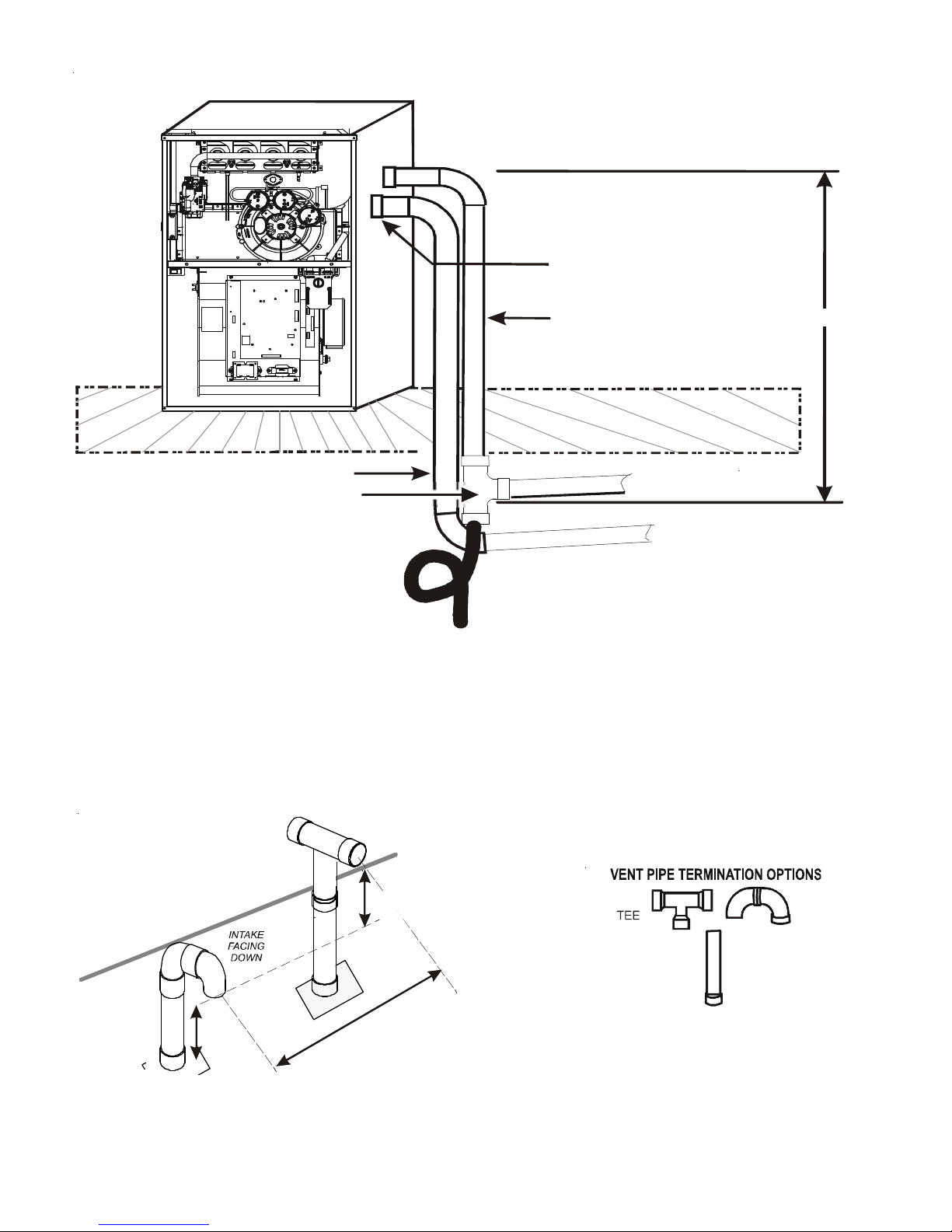
DO WN V E N TING UP F LOW MO DEL FU R N A C ES ONLY
Use alternat e vent
& combination air locations
Ven t Pipe
r
o
o
l
F
Combustion Air Pipe
Field Supplied
Drain Tee on Vent Pipe
e
c
a
p
s
l
w
a
r
C
/
t
n
e
m
e
s
a
B
All piping and fit tings must be joined per material manufacturer’s specifications
to prevent separation and flue gas leaks.
Condensate trapped
to prevent flue gas from escaping
and routed to field supplied
condensate disposal
Both Pipes Terminated
Outside Structur e
1/4” per foot min. slope
6’ MAX.
Figure 12
NOTE: T erminate both pipes in the same pressure zone (same side of roof, no major obstacles between pipes, etc.).
COMBUSTION AIR INT AKE
(OPTIONAL)
*Not re quired for
single pipe installation
E
N
I
L
F
O
O
R
12” MIN TO ROOF OR HIGHEST
ANTICIPATED SNOW LEVEL
Figures 13
TEE (OPTIONAL)
12” MIN
HEIGHT DIFFERENCE
BETWEEN
INTAKE AND VENT
”
3
-
.
X
A
M
”
6
9
ELBOWS
STRAIGHT
.
N
I
M
17
Figure 14
Page 18
DIRECT VENT (DUAL PIPE) PIPING
V
Direct vent installations require both a combustion air intake and a vent/
flue pipe. The pipes may be run horizontally and exit through the side of the
building or run vertically and exit through the roof of the building. The
pipes may be run through an existing unused chimney; however , they must
extend a minimum of 12 inches above the top of the chimney . The space
between the pipes and the chimney must be closed with a weather tight,
corrosion resistant flashing. Both the combustion air intake and a vent/
flue pipe terminations must be in the same atmospheric pressure zone.
Refer to Vent/Flue and Combustion Air Pipe - Termination Locations or
Concentric Vent Termination for specific details on termination construction. For details concerning connection of pipes to the furnace, refer to the
Vent/Flue Pipe and Combustion Pipe - Standard Furnace Connections or
Alternate Furnace Connections.
VENT/FLUE & COMBUSTION AIR PIPE LENGTHS & DIAMETERS
Refer to the following table for applicable length, elbows, and pipe diameter for construction of the vent/flue and combustion air intake
pipe systems of a direct vent (dual pipe) installation. The number of
elbows tabulated represents the number of elbows and/or tees in each
(Vent/Flue & Combustion Air Intake) pipe. Elbows and/or tees used in
the terminations must be included when determining the number of
elbows in the piping systems.
If the combustion air intake pipe is to be installed above a finished ceiling or
other area where dripping of condensate will be objectionable, insulation of
the combustion air pipe may be required. Use 1/2” thick closed cell foam
insulation such as Armaflex™ or Insultube™ where required.
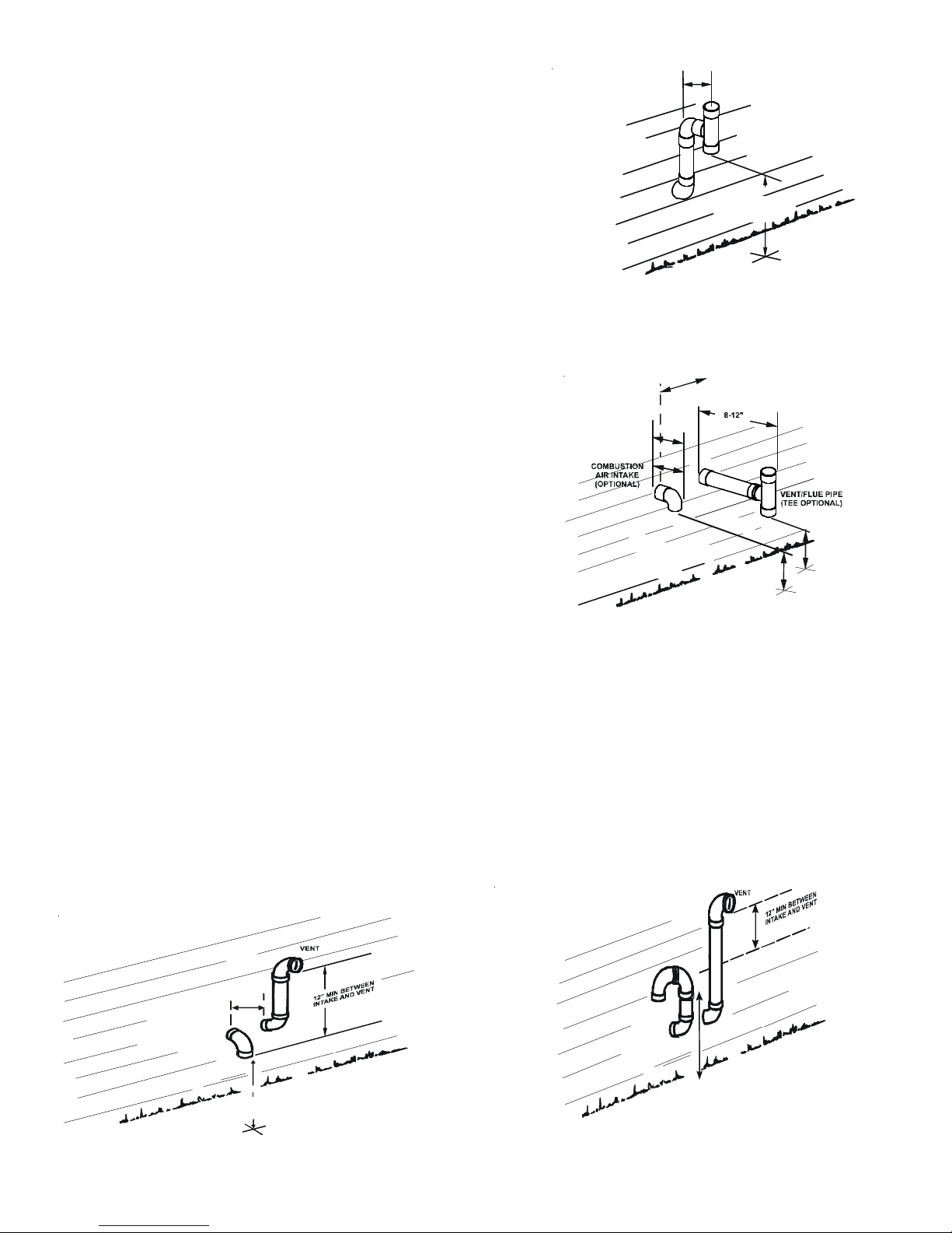
VENT/FLUE AND COMBUSTION AIR PIPE TERMINATIONS
The vent/flue and combustion air pipes may terminate vertically , as through
a roof, or horizontally , as through an outside wall.
12" MIN.
ENT/ FLUE TEE (
90° ELBOW TURNED
12" MIN. ABOVE
HIGHEST ANTICIPATED
SNOW LEVEL
OPTIONAL)
or
45° ELBOW
TURNE D DOWN or
DOW N
Horizontal Termination (Single Pipe)
Above Highest Anticipated Snow Level
Figure 15
6” MAX
4” MIN
90º OR 45°
ELBOW
12" MIN. TO GRADE OR
HIGHEST ANTICIPA TED
SNOW LEVEL
Standard Horizontal Terminations (Dual Pipe)
Figure 16
Vertical pipe terminations should be as shown in the following figure. Refer to V ent/Flue Pipe and Combustion Pipe - T ermination
Locations for details concerning location restrictions. The penetrations through the roof must be sealed tight with proper flashing
such as is used with a plastic plumbing vent.
VENT & COMBUSTION AIR INTAKE MEASUREMENTS FOR STANDARD HORIZONTAL TERMINATIONS (DUAL PIPE)
Center to center = 10” min / 24” max.
Vertical separation: 0” - 24”
Vent termination from wall = 8” min / 12” max.
Combustion air intake from wall = 6” max.
90°
ELBOWS
90°
ELBOWS
3” - 24”
12" MIN. ABOVE
HIGHEST ANTICIPATED
SNOW LEVEL
Alternate Horiz ontal Vent Terminati on (D ua l Pipe )
Figure 17
Combustion Air Intake may also be snorkeled to obtain 12” min ground clearance.
Alternate Vent Termination Above Anticipated Snow Level
(Dual Pipe)
Figure 18
18
3”-24” BETWEEN PIPES
12" MIN. ABOVE
HIGHES T ANT ICI P A TE D
SNOW LEVEL
Page 19

V ent and intake clearance to ground or anticipated snow level =
12” min.
VENT/INTAKE TERMINATIONS FOR INSTALLATION OF MULTIPLE DIRECT
VENT FURNACES
3”MIN
24”MAX
If more than one direct vent furnace is to be installed vertically through
a common roof top, maintain the same minimum clearances between the exhaust vent and air intake terminations of adjacent units
as with the exhaust vent and air intake terminations of a single unit.
If more than one direct vent furnace is to be installed horizontally
through a common side wall, maintain the clearances as in the following figure. Always terminate all exhaust vent outlets at the same
elevation and always terminate all air intakes at the same elevation.
CONCENTRIC VENT TERMINATION
Refer to the directions provided with the Concentric V ent Kit (DCVK)
for installation specifications.
SIDE WALL VENT KIT
This kit is to be used with 2” or 3” direct vent systems. The vent kit
must terminate outside the structure and may be installed with the
intake and exhaust pipes located side-by-side or with one pipe above
the other . These kits are NOT intended for use with single pipe (indirect vent) installations.
Refer to the directions furnished with the Side Wall Vent Kit (p/n
0170K00000S or 0170K000001S) for installation specifications.
C
ONDENSA TE DRAIN LINES
& D
RAIN TRAP
3” MIN
12” MIN TO GR AD E OR HIGHEST
ANTICIPATED SNOW LEVEL
Termination of Multiple Direct Vent Furnaces
Horizontal Installation
Vertical Installation
Side Wall Vent Kit
Figure 19
Figure 20
12” MIN SEPARATION
A condensing gas furnace achieves its high level of efficiency by extracting heat from the products of combustion to the point where
condensation takes place. The condensate must be collected in the furnace drain trap and routed to an appropriate drain
location in compliance with local and national codes.
Follow the bullets listed below when installing the drain system. Refer to the following sections for specific details concerning furnace
drain trap installation and drain hose hook ups.
• The drain trap supplied with the furnace must be used.
• The drain trap must be primed at time of installation.
• The drain line between furnace and drain location must meet local and nation codes.
• The drain line between furnace and drain location must maintain a 1/4 inch per foot downward slope toward the drain.
• Do not trap the drain line in any other location than at the drain trap supplied with the furnace.
• If the drain line is routed through an area which may see temperatures near or below freezing, precautions must be
taken to prevent condensate from freezing within the drain line.
• If an air conditioning coil is installed with the furnace, a common drain may be used. An open tee must be installed in
the drain line, near the cooling coil, to relieve positive air pressure from the coil’s plenum. This is necessary to prohibit
any interference with the function of the furnace’s drain trap.
NOTE: In vertical installations, air conditioning coil condensate may drain into the furnace trap as long as there is a trap
between the coil and the furnace trap and the drain pipe is not terminating below the water level of the furnace trap.
GENERAL DRAIN INFORMATION
All furnace models come with a factory installed drain trap. For vertical installations, the trap will remain in the factory
position except for a counterflow when the installer desires the drain to exit the right side. All furnace models installed
horizontally require the trap to be relocated. Many drain hoses have a built–in grommet which will provide a cabinet seal when
installed. See instructions below for your model and installation position. NOTE: Both sides of the drain trap must be
primed prior to initial furnace start up
19
Page 20

FIELD SUPPLIED DRAIN
Drain the furnace and air conditioning coil if applicable, in compliance with code requirements. In horizontal or counterflow installations, a field installed rubber coupling will allow the drain
trap to be removed for cleaning. The drain trap must be primed
before initial furnace start up. When an air conditioning coil
drain is connected to the field supplied furnace drain, it must be
vented, with an open tee installed at a height no higher than the
bottom of the furnace collector box to prevent air conditioning
condensate from backing up into the furnace if the common drain
was blocked.
UPFLOW MODEL INSTALLED VERTICALLY
The trap and factory installed hoses remain as shipped. The furnace drain may exit either the right or left side of the furnace
cabinet.
DRAIN EXITING RIGHT SIDE
1. Locate and Install the 45º pipe / hose drain coupling from
the outside of the cabinet (barbed end goes in the cabinet)
through hole in the right side of the cabinet and secure with
two field supplied #8 self-tapping screws (see Figure 22).
2. Locate the long drain hose #3 and cut at line “A” .
3. Install large end of hose #3 to trap outlet and secure with
1.25" clamp.
4. Install smaller end of hose #3 on 45º elbow and secure with
1" clamp.
5. Refer to Field Supplied Drain section for instructions on field
supplied / installed drain on outlet of furnace trap.
#1
#4
6
#
and not all hose s w i ll be shipped with all model s.
#2
#7
#9
#11
Figure 21
NOTE:
Hoses are model specific
#5
#
3
#8
#10
Coupling
100 Degree
Elbow
DRAIN EXITING LEFT SIDE
1. Install the 45 degree pipe / hose drain coupling
from the outside of the cabinet (barbed end goes
in the cabinet) through the hole in the left side of
the cabinet and secure with two field supplied #8
self-tapping screws (see Figure 22).
2. Locate the long drain hose #3 and cut at “B” line
for a 17.5" cabinet; cut at line “C” for a 21" cabinet;
do not cut for a “D” width cabinet.
3. Install large end of hose #3 to trap outlet and secure
with 1.25" clamp.
4. Install smaller end of hose #3 on 45º elbow and
secure with 1" clamp.
5. Refer to Field Supplied Drain section for instructions
on field supplied / installed drain on outlet of
furnace trap.
UPFLOW MODEL INSTALLED HORIZONTALLY WITH
RIGHT SIDE DOWN
Minimum 5 ½" clearance is required for the drain trap
beneath the furnace.
1. Remove the clamps from both ends of the drain
hoses.
2. Remove the two screws holding the drain trap to
the blower deck.
3. Remove the trap and two hoses from the blower deck
45 degree
barb-pipe
adapter
Hos e #1
Hose #2
45 degree
barb-pipe
adapter
Installer selects right or left side drain
and installs this hose accordingly.
Figure 22
20
Page 21

4. Remove the two plugs from the right side of the
cabinet and install them in the blower deck.
5. (Draining the Vent Elbow ) Locate hose #5 and
cut it at line “C”. Install the cut end of hose #5
from outside the cabinet through the cabinet
drain hole nearest the top. Secure it to the barbed
fitting in the elbow with a red clamp.
6. (Draining the Collector Box) Install the nongrommet end of hose #11 from outside the
cabinet in the bottom drain hole. Install on
collector box and secure with a silver clamp.
7. Use two silver clamps and secure the hoses to
drain trap. The trap outlet faces the front of the
furnace. Secure the trap to the cabinet using two
screws removed in step 2 by inserting the two
screws through the large set of holes in the top
mounting tabs of the trap into the two predrilled
holes in the side of the cabinet.
8. Refer to Field Supplied Drain section for
instructions on field supplied / installed drain on outlet of furnace trap.
UPFLOW MODEL INSTALLED HORIZONTALLY WITH LEFT SIDE DOWN
Minimum 5 ½" clearance is required for the drain trap beneath the furnace.
Hose #11
Hose #5-Cut at “C”
Figure 23
*Also see Front Cover Pressure Switch Tube Location on page 10
1. Remove the clamps from the two drain tubes on the trap.
2. Remove the two screws holding the drain trap to the blower deck.
3. Remove the trap and hoses from the blower deck .
4. Remove the two plugs from the left side of the cabinet and install them in the blower deck.
5. (Draining the Vent Elbow) Locate hose #6. Measuring from the non-grommet end; cut off and discard 1 ½” for a “D”
width cabinet, 5” for a “C” width cabinet, 8 ½” for a “B” width cabinet.
6. Remove the rubber plug from vent – drain elbow side
port. Place hose #6 on the vent – drain elbow side port
and secure with a silver clamp .
7. Place cap on vent – drain elbow barb fitting and
secure with red clamp
8. Locate hose #5 and cut 3” from the non-grommet end.
Discard the section without the grommet.
9. Insert the cut end of tube #5 through the lower cabinet
drain hole.
10. Connect hose #6 & hose #5 using 100º elbow and
secure with two red clamps
11.(Draining the Collector Box) Install the non-grommet
end of hose #11 from outside the cabinet in the bottom
drain hole. Install on collector box and secure with a
silver clamp.
Hose #6
Hose #5
Hose #11
12.Use two silver clamps and secure the hoses to drain
trap. The trap outlet faces the front of the furnace.
Secure the trap to the cabinet using two screws
Figure 24
removed in step 2 by inserting the two screws through
the large set of holes in the top mounting tabs of the trap into the two predrilled holes in the side of the cabinet.
13.Place cap on vent – drain elbow barb fitting and secure with red clamp.
14.Refer to Field Supplied Drain section for instructions on field supplied / installed drain on outlet of furnace trap.
21
Page 22

COUNTERFLOW MODEL INSTALLED VERTICALLY
The furnace drain may exit the right or left side of the furnace cabinet (left side preferred) Trap and factory installed hoses remain as
shipped if the drain will exit the left side of the cabinet. Draining
from the right side requires re-location of the trap to outside the
cabinet.
DRAIN EXITING LEFT SIDE
1. Install a field supplied rubber coupling secured with a 1 1/4”
clamp to enable removing the trap for future cleaning. Alternately,
a PVC fitting may be glued on the trap outlet.
2. Install drain per local and National codes.
DRAIN EXITING RIGHT SIDE
1. Remove hose clamps and hoses from trap.
2. Remove trap.
3. (Draining the Vent Elbow) Insert the non-grommet end hose #10
into the cabinet back drain hole. Secure on vent – drain elbow
barb fitting with a red clamp.
4. Insert 100º elbow into the cut end and secure with red clamp.
5. (Draining the Collector Box) Insert non-grommet end of hose
#9 into the cabinet front drain hole and secure on collector
box drain port with a silver clamp.
6. Mate the drain trap inlets to the hoses and secure with silver
clamps.
7. Line up the trap mounting holes with the pre-drilled holes in
the furnace and secure with 2 screws removed in step 2.
8. Refer to Field Supplied Drain section for instructions on field
supplied / installed drain on outlet of furnace trap.
Hose #5 x 2
Hose #4 x 2
Figure 25
COUNTERFLOW MODEL INSTALLED HORIZONTALLY WITH RIGHT
SIDE DOWN
Minimum 5 ½" clearance is required for the drain trap beneath
the furnace.
*Also see Front Cover Pressure Swith Tube Location on page
10
1. Remove hose clamps and hoses from trap.
2. Remove trap.
3. (Draining the Collector Box) From outside the cabinet,
insert the non-grommet end hose #8 into the back drain
hole.
4. Secure to collector box drain port using a silver clamp.
5. (Draining the Vent Elbow) From outside the cabinet, insert
the non-grommet end of hose #7 into the front cabinet
drain hole and secure on the vent – drain elbow barb fitting
using a red clamp
6. Mate the trap inlets to the hoses, the outlet of the trap
must face the original bottom of the furnace. Secure with
silver clamps.
Hose #8
Figure 27
7. Fasten the drain trap to the cabinet with two screws
removed in step 2
8. Refer to Field Supplied Drain section for instructions on field supplied / installed drain on outlet of furnace trap.
Drain Port
Hose #7
22
Page 23

COUNTERFLOW MODEL INSTALLED HORIZONTALLY WITH LEFT SIDE DOWN
Minimum 5 ½" clearance is required for the drain trap beneath the furnace.
1. Remove hose clamps and hoses from trap.
2. Remove trap.
3. Remove plugs from left side of cabinet and
install in blower deck.
4. (Draining the Collector Box) Locate hose #4 and
place the radius end on the collector box drain
port, secure with a silver clamp.
5. Locate hose #2, insert from outside the cabinet
in the drain hole closest to the front of the
cabinet, insert a coupling and secure with a red
clamp.
6. Mate coupling to hose #4 and secure with a red
clamp.
7. (Draining the V ent Elbow) Remove plug from vent
– drain elbow side port.
8. Locate hose #4 and place radius end on the side
port of vent – drain elbow and secure with a red
clamp.
9. Install cap on vent drain elbow barb fitting
Hose #4
and secure with red clamp.
10.Insert PVC pipe into hose #4 and secure with a
red clamp.
11.Locate hose #5, insert it from outside the
cabinet in the drain hole farthest from the front of the cabinet.
12.Insert 100º elbow in hose #5 and secure with a red clamp.
13.Locate another hose #5 cut a 5.25" straight section and discard the radius end.
14.Connect the 5.25’ straight section to the 100º elbow and the PVC pipe and secure with red clamps.
15.Mate trap inlets and hoses and secure with silver clamps, drain trap outlet must point to the original bottom of the
furnace.
16.Secure trap to furnace using two screws removed in step 2.
17.Refer to Field Supplied Drain section for instructions on field supplied / installed drain on outlet of furnace trap.
Hose #4
Hose #5 x2
Figure 28
E
LECTRICAL CONNECTIONS
WIRING HARNESS
The wiring harness is an integral part of this furnace. Wires are
color coded for identification purposes. Refer to the wiring diagram for wire routings. If any of the original wire as supplied
with the furnace must be replaced, it must be replaced with wiring material having a temperature rating of at least 105° C. Any
replacement wiring must be a copper conductor .
115 VOLT LINE CONNECTIONS
Before proceeding with electrical connections, ensure that the
supply voltage, frequency , and phase correspond to that specified
on the unit rating plate. Power supply to the furnace must be NEC
Class 1, and must comply with all applicable codes. The furnace
must be electrically grounded in accordance with local codes or , in
their absence, with the latest edition of The National Electric
Code, ANSI NFPA 70 and/or The Canadian Electric Code CSA C22.1.
Use a separate fused branch electrical circuit containing properly
sized wire, and fuse or circuit breaker . The fuse or circuit breaker
WARNING
HIGH VOLTAGE !
TO
AVOID THE RISK OF ELECTRICAL SHOCK, WIRING TO
THE UNIT MUST BE POLARIZED AND GROUNDED
WARNING
HIGH VOLTAGE !
TO
AVOID PERSONAL INJURY OR DEATH DUE TO
ELECTRICAL SHOCK, DISCONNECT ELECTRICAL POWER
BEFORE SERVICING OR CHANGING ANY ELECTRICAL
WIRING
.
CAUTION
L
ABEL ALL WIRES PRIOR TO DISCONNECTION WHEN SERVICING
CONTROLS
OPERATION
23
. W
IRING ERRORS CAN CAUSE IMPROPER AND DANGEROUS
. V
ERIFY PROPER OPERATION AFTER SERVICING
.
.
Page 24

must be sized in accordance with the maximum overcurrent protection specified on the unit rating plate. An electrical disconnect
must be provided at the furnace location.
Connect hot, neutral, and ground wires as shown in the wiring diagram located on the unit’s blower door. For direct vent
applications, the cabinet opening to the junction box must be sealed air tight using either an UL approved bushing such as Heyco
Liquid Tight or by applying non-reactive UL approved sealant to bushing.
Line polarity must be observed when making field connections. Line voltage connections can be made through either the right or
left side panel. The furnace is shipped configured for a left side (right side for counterflows) electrical connection with the
junction box located inside the burner compartment. T o make electrical connections through the opposite side of the furnace, the
junction box must be relocated to the other side of the burner compartment prior to making electrical connections. T o relocate the
junction box, follow the steps shown below .
NOTE: Wire routing must not to interfere with circulator blower operation, filter removal, or routine maintenance.
JUNCTION BOX RELOCATION
WARNING
Line voltage connections can be made through either the right
or left side panel. The furnace is shipped configured for a left
side electrical connection. To make electrical connections
through the opposite side of the furnace, the junction box
must be relocated to the right side prior to making electrical
connections. To relocate the junction box, perform the following steps.
1. Remove the burner compartment door.
2. Remove and save the two screws securing the junction box
to the side panel.
3. Relocate junction box and associated plugs and grommets to
opposite side panel. Secure with screws removed in step 2.
T o ensure proper unit grounding, the ground wire should run from
the furnace ground screw located inside the furnace junction box
all the way back to the electrical panel. NOTE: Do not use gas
piping as an electrical ground. T o confirm proper unit grounding,
turn off the electrical power and perform the following check.
E
DGES OF SHEET METAL HOLES MAY BE SHARP
PRECAUTION WHEN REMOVING HOLE PLUGS
. USE
.
GLOVES AS A
WARNING
TO
PREVENT PERSONAL INJURY OR DEATH DUE TO ELECTRIC SHOCK
DISCONNECT ELECTRICAL POWER BEFORE INSTALLING OR SERVICING THIS
UNIT
.
,
WARNING
HIGH VOLTAGE !
TO
AVOID THE RISK OF INJURY, ELECTRICAL SHOCK OR
DEATH, THE FURNACE MUST BE ELECTRICALLY
GROUNDED IN ACCORDANCE WITH LOCAL CODES OR IN
THEIR ABSENCE, WITH THE LATEST EDITION OF THE
ATIONAL ELECTRIC CODE
N
.
1. Measure resistance between the neutral (white) connection and
one of the burners.
2. R esistance should measure 10 ohms or less.
This furnace is equipped with a blower door interlock switch which
TO
AVOID THE RISK OF INJURY, ELECTRICAL SHOCK OR DEATH, THE
FURNACE MUST BE ELECTRICALLY GROUNDED IN ACCORDANCE WITH
LOCAL CODES OR, IN THEIR ABSENCE, WITH THE LATEST EDITION OF THE
N
ATIONAL ELECTRICAL CODE
WARNING
.
interrupts unit voltage when the blower door is opened for servicing. Do not defeat this switch.
24 VOLT THERMOSTAT WIRING
As a two-stage non-communicating furnace, the furnace integrated
control module provides terminals for both “W1” and “W2”, and
“Y1” and “Y2” thermostat connections. This allows the furnace to
support the following system applications: ‘Two-Stage Heating
Only’, ‘Two-Stage Heating with Single Stage Cooling’, and ‘T woStage Heating with Two-Stage Cooling’. Refer to the following
figures for proper connections to the integrated control module.
Low voltage connections can be made through either the right or
left side panel. Thermostat wiring entrance holes are located in
W
IRE ROUTING MUST NOT INTERFERE WITH CIRCULATOR BLOWER
OPERATION, FILTER REMOVAL OR ROUTINE MAINTENANCE
REMOVABLE PLUG CONNECTOR IS PROVIDED WITH THE CONTROL TO
A
MAKE THERMOSTAT WIRE CONNECTIONS
WIRE CONNECTIONS MADE TO THE PLUG, AND REPLACED
STRONGLY
WIRES INTO A SINGLE TERMINAL
ENSURE ONE
DO SO MAY RESULT IN INTERMITTENT OPERATION
IMPORTANT NOTE
.
. T
HIS PLUG MAY BE REMOVED
. IT IS
RECOMMENDED THAT YOU DO NOT CONNECT MULTIPLE
. W
IRE NUTS ARE RECOMMENDED TO
18 A WG
WIRE IS USED FOR EACH TERMINAL
. F
AILURE TO
.
,
the blower compartment. The following figure shows connections
for a “heat/cool system”.
This furnace is equipped with a 40 V A transformer to facilitate use with most cooling equipment. Consult the wiring diagram, located
on the blower compartment door , for further details of 115 V olt and 24 Volt wiring.
24
Page 25

NOTE: For single stage cooling applications, a jumper may be required between Y1 and Y2 at the furnace control in order to achieve
the desired single stage cooling airflow . Use of ramping profiles and dehumidification features require a jumper between Y1 and O.
NOTE: Thermostat “R” required if outdoor unit is equipped with a Comfort Alert™ module or if the out door unit is a
part of the ComfortNet™™ family of equipment AND is wired as a non-communicating system.
R
Condensing Unit
(Single-Stage Cooling)
NOTE: To apply a single-stage Heating Thermostat, the thermostat selector switch on the
Integrated Contr ol Module must be se t on single-stage.
Thermostat - Single -Stage Heating with Single-Stage Cooling
R
Furnace Integrated
Control Module
Dehumidistat
[Optional]
Y C
Remote
Condensing Unit
(Single-Stage Cooling)
R
NEU
Thermostat - Two-Stage Heating with Single-Stage Cooling
Figure 30
Y C
Remote
R
NEU
Furnace Integrated
Control Module
Dehumidistat
[Optional]
Figure 29
Y2
Y2
Y2
Remote
Condensing Unit
(Two-Stage Cooling)
Thermostat - Two-Stage Heating with Two-Stage Cooling
Thermostat Wiring Diagrams
W1 W2
W1 W2
Figu re 31
NEU
Furnace Integrated
Dehumidistat
[Optional]
Control Module
SINGLE-STAGE HEATING THERMOSTAT APPLICATION
A single-stage thermostat with only one heating stage may be used to control this furnace. The application of a single-stage
thermostat offers a timed transition from low to high fire. The furnace will run on low stage for a fixed period of time before
stepping up to high stage to satisfy the thermostat’ s call for heat. The delay period prior to stepping up can be set at either
a fixed 5 minute time delay or a load based variable time between 1 and 12 minutes (AUTO mode). If the AUTO mode is
selected, the control averages the cycle times of the previous three cycles and uses the average to determine the time to
transition from low stage to high stage.
To use a single-stage thermostat, turn off power to
the furnace, move the thermostat selection DIP switch
Heat OFF Delay
DIP Switches
ONOFF
to the OFF position. Set the desired transition time
by setting the transition delay DIP switch to the desired ON/OFF position. Turn power back on. Refer to
the following figure.
3
4
Thermostat
Stage Delay
S1
24 VOLT DEHUMIDISTAT WIRING
The optional usage of a dehumidistat allows the furnace’s
circulator blower to operate at a slightly lower speed (85%
of desired speed) during a combined thermostat call for
cooling and dehumidistat call for dehumidification. This can be done through an independent dehumidistat or through a thermostat’ s
DEHUM terminal (if available). This lower blower speed enhances dehumidification of the conditioned air as it passes through the AC
25
Figure 32
Move to the ON po s i tio n
to select two-stage
thermostat or OFF to
select single stage
thermostat
If 3 is ON, #4 is ignored.
Move to the ON position
to sele c t Auto tr a n sition
delay or OFF for 5 minute
transition delay
Page 26

coil. For proper function, a dehumidistat applied to this furnace must operate on 24 V AC and utilize a switch which opens on humidity
rise. Refer to the “Thermostat Wiring Diagrams” figure for additional wiring details. (See Figure 33)
T o install/connect a dehumidistat:
1. T urn OFF power to furnace.
2. T o enable the dehumidify function on the integrated control module, set the dehumidification ENABLE dip switch from OFF to
ON.
3. Secure the dehumidistat neutral wire (typically the white lead) to the terminal marked “DEHUM” on the furnace integrated
control module.
4. Secure the dehumidistat hot wire (typically the black lead) to the terminal marked “R” on the furnace integrated control
module.
5. Secure the dehumidistat ground wire (typically the green lead) to the ground screw on the furnace junction box. NOTE: Ground
wire may not be present on all dehumidistats.
6. T urn ON power to furnace.
Once the switch is set, the dehumidify function is enabled during a combi-
nation call for cooling (T -Stat) and dehumidification (DEHUM-Stat).
FOSSIL FUEL APPLICATIONS
This furnace can be used in conjunction with a heat pump in a fossil fuel
1
2
OFF
ON
S5
Move to the ON posit i on
to enable dehumidification.
DEHUM
TRIM ENABLE
Select ON to enable
trim selected by S3 3 & 4.
Figure 33
application. A fossil fuel application refers to a combined gas furnace and
heat pump installation which uses an outdoor temperature sensor to determine the most cost efficient means of heating (heat pump
or gas furnace).
A heat pump thermostat with three stages of heat is required to properly use a two-stage furnace in conjunction with a heat pump.
Refer to the fossil fuel kit installation instructions for additional thermostat requirements.
Strictly follow the wiring guidelines in the fossil fuel kit installation instructions. All furnace connections must be made to the furnace
two-stage integrated control module and the “FURNACE” terminal strip on the fossil fuel control board.
115 VOLT LINE CONNECTION OF ACCESSORIES (HUMIDIFIER AND
ELECTRONIC AIR CLEANER)
The furnace integrated control module is equipped with line voltage accessory terminals for controlling power to an optional fieldsupplied humidifier and/or electronic air cleaner .
The accessory load specifications are as follows:
T urn OFF power to the furnace before installing any accessories.
Follow the humidifier or air cleaner manufacturers’ instructions
for locating, mounting, grounding, and controlling these accessories. Accessory wiring connections are to be made through the 1/4"
quick connect terminals provided on the furnace integrated control module. The humidifier and electronic air cleaner hot terminals are identified as HUM and EAC. The humidifier and
electronic air cleaner neutral terminals are identified as NEUTRAL. All field wiring must conform to applicable codes. Connections should be made as shown. (See Figure 34)
HIGH VOLTAGE !
TO
AVOID PERSONAL INJURY OR DEATH DUE TO
ELECTRICAL SHOCK, DISCONNECT ELECTRICAL POWER
BEFORE SERVICING OR CHANGING ANY ELECTRICAL
WIRING
.
Humidifier 1.0 Amp max im um at 120 VA C
Elect ronic Ai r Cleaner 1.0 Amp max im um at 120 VA C
WARNING
26
Page 27

If it is necessary for the installer to supply additional line voltage wiring
to the inside of the furnace, the wiring must conform to all local codes,
and have a minimum temperature rating of 105°C. All line voltage
wire splices must be made inside the furnace junction box.
The integrated control module single humidifier terminal (HUM) is
energized with 115 volts whenever the induced draft blower is energized. The integrated control module electronic air cleaner terminals
(EAC) are energized with 115 volts whenever the circulator blower is
energized. This terminal can also be used to provide 115 volt power
to a humidifier transformer. The remaining primary transformer
wire would be connected to the Line N on the control board.
In addition, the control is equipped with a dedicated humidification relay which is available through ¼ inch terminals HUM-IN and
HUM-OUT. Similar to the HUM terminal, when utilizing legacy connections, this relay will be closed during normal heating operation. HUM IN must be powered with the desired voltage (24 vac
from the R terminal or 115 vac from L1 terminal). The internal
relay will close during a call for heat. Also, the control can provide
additional humidification features when wired to a communicating thermostat (1, 2, R, C connections). If the communicating
thermostat is not capable of providing a humidification call, this
dedicated relay will function exactly as mentioned above with a legacy setup. If the communicating thermostat is capable of
providing a humidification call the user is now provided with 3 modes of operations which can be selected within the
thermostat user menu.
Accesso ries Wiring
Figure 34
1. ON: Humidifier is turned on with a heat
demand.
2. OFF: Humidifier remains off (relay never
closes).
3. IND: Humidifier will cycle with humidification demand, independent of heat demand.
This mode allows the user to select one of 4
fan speeds (25, 50, 75, and 100%).
NEUTRAL
24 VOLT
COMMON
Figure 35A
HUM-OUT
HUM-OUT
HUM-IN
HUM-IN
Figure 35B
27
Page 28

AUXILIARY ALARM SWITCH:
The control is equipped with a 24V AC Auxiliary Alarm Input (12 inch purple / white wire attached to pin 6 of 15 pin connector)
which can be utilized with communicating mode setups (typically used for condensate switch wiring but could be used with
compatible C02 sensors or Fire Alarms).
Legacy mode use
In a legacy system (Non-communicating), this auxiliary alarm input is not operational. Any auxiliary alarm switch must be
used to interrupt Y1 signal either to IFC or to UC.
Communication mode use
This feature can be activated or deactivated through the thermostat user menus. By default, an AUX switch is normally
closed and opens when the water level in the evaporator coil base pan reaches a particular level. The control will respond by
turning off the outdoor compressor and display the proper fault codes. If the AUX switch is detected closed for 30 seconds,
normal operation resumes and error messages are no longer displayed. Installer must wire control voltage (24V AC) to AUX
switch to ensure the Auxiliary Alarm Input has 24V AC during normal operation.
GAS S
UPPLY AND PIPING
The furnace rating plate includes the approved furnace gas input
rating and gas types. The furnace must be equipped to operate
CAUTION
on the type of gas applied. This includes any conversion kits
required for alternate fuels and/or high altitude.
Inlet gas supply pressures must be maintained within the ranges
specified in the following table. The supply pressure must be
PREVENT UNRELIABLE OPERATION OR EQUIPMENT DAMAGE, THE
INLET GAS SUPPLY PRESSURE MUST BE AS SPECIFIED ON THE UNIT
RATING PLATE WITH ALL OTHER HOUSEHOLD GAS FIRED APPLIANCES
OPERATING
.
TO
constant and available with all other household gas fired appliances operating. The minimum gas supply pressure must be maintained to prevent unreliable ignition. The maximum must not be
exceeded to prevent unit overfiring.
Natur al G as Minimum: 4.5" w.c . Maximum: 10. 0" w .c.
Pro pane Gas Minimum: 11. 0" w.c. Maximum: 13. 0" w . c.
INLET GAS SUPPLY PRESSURE
HIGH ALTITUDE DERATE
When this furnace is installed at high altitude, the appropriate High Altitude orifice kit must be applied. This is required due to the
natural reduction in the density of both the gas fuel and combustion air as altitude increases. The kit will provide the proper design
certified input rate within the specified altitude range.
High altitude kits are purchased according to the installation altitude and usage of either natural or propane gas. Consult the
furnace Specification Sheet for appropriate kits.
Do not derate the furnace by adjusting the manifold pressure to a lower pressure than specified on the furnace rating plate. The
combination of the lower air density and a lower manifold pressure will prohibit the burner orifice from drawing the proper amount of
air into the burner . This may cause incomplete combustion, flashback, and possible yellow tipping.
In some areas the gas supplier may artificially derate the gas in an effort to compensate for the effects of altitude. If the gas is
artificially derated, the appropriate orifice size must be determined based upon the BTU/ft3 content of the derated gas and the
altitude. Refer to the National Fuel Gas Code, NFP A 54/ANSI Z223.1, and information provided by the gas supplier to determine the
proper orifice size.
A different pressure switch may be required at high altitude regardless of the BTU/ft3 content of the fuel used. Consult the furnace
Specification Sheet for pressure switch.
PROPANE GAS CONVERSION
This unit is configured for natural gas. The appropriate
manufacturer’s propane gas conversion kit, must be applied for
propane gas installations. Refer to the Propane Gas and/or High
Altitude Installations for details.
Consult the furnace Specification Sheet for a listing of appropriate kits. The indicated kits must be used to insure safe and
proper furnace operation. All conversions must be performed by a
qualified installer , or service agency .
WARNING
P
OSSIBLE PROPERTY DAMAGE, PERSONAL INJURY OR DEATH MAY
OCCUR IF THE CORRECT CONVERSION KITS ARE NOT INSTALLED
APPROPRIATE KITS MUST BE APPLIED TO ENSURE SAFE AND PROPER
FURNACE OPERATION
QUALIFIED INSTALLER OR SERVICE AGENCY
28
. ALL
CONVERSIONS MUST BE PERFORMED BY A
.
. THE
Page 29

GAS VALVE
_
This unit is equipped with a 24 volt gas valve controlled during furnace operation by the integrated control module. As shipped, the
valve is configured for natural gas. The valve is field convertible for use with propane gas by replacing the regulator spring with a
propane gas spring from an appropriate manufacturer’ s propane gas conversion kit. T aps for measuring the gas supply pressure and
manifold pressure are provided on the valve.
The gas valve has a manual ON/OFF control located on the valve itself. This control may be set only to the “ON” or “OFF” position.
Refer to the lighting instructions label or Startup Procedure & Adjustment for use of this control during start up and shut down
periods.
GAS PIPING CONNECTIONS
The gas piping supplying the furnace must be properly sized based
”
WARNING
.
”
1
1¼” 1 ½”
on the gas flow required, specific gravity of the gas, and length of
the run. The gas line installation must comply with local codes, or
in their absence, with the latest edition of the National Fuel Gas
Code, NFP A 54/ANSI Z223.1.
To connect the furnace to the building’s gas piping, the installer
must supply a ground joint union, drip leg, manual
shutoff valve, and line and fittings to connect to gas
valve. In some cases, the installer may also need to
supply a transition piece from 1/2" pipe to a larger
pipe size.
The following stipulations apply when connecting gas
piping. Refer to Gas Piping Connections figure for
typical gas line connections to the furnace.
• Gas piping must be supported external to the
furnace cabinet so that the weight of the gas
line does not distort the burner rack, manifold
or gas valve.
• Use black iron or steel pipe and fittings for building
piping. Where possible, use new pipe that is
properly chamfered, reamed, and free of burrs
and chips. If old pipe is used, be sure it is clean
and free of rust, scale, burrs, chips, and old pipe
joint compound.
Length of
Pipe in Feet
10 132 278 520 1050 1600
20 92 190 350 730 1100
30 73 152 285 590 980
40 63 130 245 500 760
50 56 115 215 440 670
60 50 105 195 400 610
70 46 96 180 370 560
80 43 90 170 350 530
90 40 84 160 320 490
100 38 79 150 305 460
(Pres sure 0.5 psig or les s and pressure drop of 0.3" W.C. ; Based on
0.60 Specific gravity Gas)
TO
AVOID POSSIBLE UNSATISFACTORY OPERATION OF EQUIPMENT
DAMAGE DUE TO UNDERFIRING OR EQUIPMENT, USE THE PROPER SIZE
OF NATURAL/PROPANE GAS PIPING NEEDED WHEN RUNNING PIPE FROM
THE METER/TANK TO THE FURNACE
Natural Gas Capacity of Pipe
In Cubic Feet of Gas Per Hour (CFH)
Nominal Black Pipe Size
”
½
¾
• Use pipe joint compound on male threads ONLY .
Always use pipe joint compound (pipe dope) that
is APPROVED FOR ALL GASSES. DO NOT apply
compound to the first two threads.
CFH = BT UH Fur na ce Input _______
_________
Heating Value of Gas (BTU/Cubic Foot)
• Use ground joint unions.
• Install a drip leg to trap dirt and moisture before it can enter the gas valve. The drip leg must be a minimum of three inches
long.
• Install a 1/8" NPT pipe plug fitting, accessible for test gage connection, immediately upstream of the gas supply connection to
the furnace.
• Always use a back-up wrench when making the connection to the gas valve to keep it from turning. The orientation of the gas
valve on the manifold must be maintained as shipped from the factory . Maximum torque for the gas valve connection is 375
in-lbs; excessive over-tightening may damage the gas valve.
• Install a manual shutoff valve between the gas meter and unit within six feet of the unit. If a union is installed, the union must
be downstream of the manual shutoff valve, between the shutoff valve and the furnace.
• T ighten all joints securely .
• Connect the furnace to the building piping by one of the following methods:
– Rigid metallic pipe and fittings.
29
Page 30

– Semi-rigid metallic tubing and metallic fittings.
Aluminum alloy tubing must not be used in exterior
locations. In order to seal the grommet cabinet
penetration, rigid pipe must be used to reach the
outside of the cabinet. A semi-rigid connector to the
gas piping may be used from there.
• Use listed gas appliance connectors in accordance with their
instructions. Connectors must be fully in the same room as
the furnace.
• Protect connectors and semirigid tubing against physical
and thermal damage when installed. Ensure aluminum-alloy
tubing and connectors are coated to protect against external
corrosion when in contact with masonry , plaster , or insulation,
or subjected to repeated wetting by liquids such as water
(except rain water), detergents, or sewage.
Manual Shut Off Valve
(upstream from ground joint pipe union)
Alternate
Gas Line
Location
Alternate
Gas Line
Location
Manifold
Burners
Gas Valve
*Ground
Joint
Pipe
Union
*NOTE: Union may be inside furnace cabinet where allowed by local codes.
UPFLOW
Figure 36
Manual Shut Off Valve
(upstream from
Alternate
Union
Location
ground joint pipe union)
Manual Shut Off Valve
(upstream from
ground joint
pipe union)
*Ground
Joint
Pipe
Union
Drip Leg
Grommet
in Sta ndard
Gas Line
Hole
*Ground
Joint
Pipe Unio n
Grommet
in Standard
Gas Line
Hole
Drip Leg
Burners
*NOTE: Union may be inside furnace cabinet where allowed by local codes.
COUNTERFLOW
Figu r e 3 7
*Ground
Joint
Pipe Unio n
Plug in
Alternate
Gas Line
Hole
Gas Valve
The gas piping may enter the left or right side of the furnace
cabinet. The installer must supply rigid pipe long enough to reach
the outside of the cabinet to seal the grommet cabinet penetration. A semi-rigid connector to the gas piping can be used outside
the cabinet per local codes. 1/2” NPT pipe and fittings are required. For models with an “L” shaped manifold, a 4 1/2”
long nipple is required. For models with a hook shaped manifold, a 2” long nipple is required.
Standa rd Ga s Lin e Ho le
Burners
Grommet in
Manifold
Drain Trap
Drip Leg
Plug in Alternate Gas Line Hole
Gas
Valve
UPFLOW - HORIZONTAL LEFT
Figure 38
Plug in Main Gas Line Hole
Manual Shut Off Valve
(upstream from
ground joint
pipe union)
A semi-rigid connector to the gas piping can be used outside
the cabinet per local codes. From the elbow , the length of pipe
and the fittings required will vary by the side chosen, location
of union and cabinet width. The union may be placed inside or
outside of the cabinet.
30
COUNTERFLOW - HORIZONTAL RIGHT
Figure 39
Gas Piping Connections
Page 31

GAS PIPING CHECKS
Before placing unit in operation, leak test the unit and gas connections.
Check for leaks using an approved chloride-free soap and water
solution, an electronic combustible gas detector , or other approved
testing methods.
TO
AVOID THE POSSIBILITY OF EXPLOSION OR FIRE, NEVER USE A MATCH
OR OPEN FLAME TO TEST FOR LEAKS
WARNING
.
NOTE: Never exceed specified pressures for testing. Higher
pressure may damage the gas valve and cause subsequent overfiring, resulting in heat exchanger failure.
Disconnect this unit and shutoff valve from the gas supply piping system before pressure testing the supply piping system with
pressures in excess of 1/2 psig (3.48 kPa).
Isolate this unit from the gas supply piping system by closing its external manual gas shutoff valve before pressure testing supply
piping system with test pressures equal to or less than 1/2 psig (3.48 kP A).
PROPANE GAS TANKS AND PIPING
A gas detecting warning system is the only reliable way to detect a
propane gas leak. Rust can reduce the level of odorant in propane
gas. Do not rely on your sense of smell. Contact a local propane
gas supplier about installing a gas detecting warning system. If
the presence of gas is suspected, follow the instructions listed in
the Safety Precautions section of this manual.
All propane gas equipment must conform to the safety standards
of the National Board of Fire Underwriters, NBFU Manual 58.
For satisfactory operation, propane gas pressure must be 10” WC
IF
THE GAS FURNACE IS INSTALLED IN A BASEMENT, AN EXCAVATED
AREA OR CONFINED SPACE, IT IS STRONGLY RECOMMENDED TO
CONTACT A PROPANE SUPPLIER TO INSTALL A GAS DETECTING WARNING
DEVICE IN CASE OF A GAS LEAK
INCE PROPANE GAS IS HEAVIER THAN AIR, ANY LEAKING GAS CAN
•
S
SETTLE IN ANY LOW AREAS OR CONFINED SPACES
ROPANE GAS ODORANT MAY FADE, MAKING THE GAS UNDETECTABLE
•
P
EXCEPT WITH A WARNING DEVICE
WARNING
.
.
.
at the furnace manifold with all gas appliances in operation. Maintaining proper gas pressure depends on three main factors:
1. Vaporization rate, depending on temperature of the liquid, and “wetted surface” area of the container or containers.
2. Proper pressure regulation. (Two-stage regulation is recommended for both cost and efficiency).
3. Pressure drop in lines between regulators, and between second stage regulator and the appliance. Pipe size will depend
on length of pipe run and total load of all appliances.
Complete information regarding tank sizing for vaporization, recommended regulator settings, and pipe sizing is available from most
regulator manufacturers and propane gas suppliers.
Since propane gas will quickly dissolve white lead and most standard commercial compounds, special pipe dope must be used. Always
use a pipe thread sealant approved for all gases.
Refer to the following illustration for typical propane gas installations and piping.
31
200 PSIG
Maximum
5 to 15 PSIG
(20 PSIG Max.)
Figure 40
First Stage
Regulator
Propane Gas Installation (Typ.)
Continuous
Second Stage
Regulator
11" W.C .
Page 32

g
Sizi ng B etw een F irst an d S e cond Stage Regu la tor*
Maximum Propane Capacities listed are based on 2 psig pressure drop at 10 psig setting.
Capacities in 1,000 BTU/hour.
Pipe or
Tubing
Leng t h
Feet
10 730 1,700 3,200 5,300 8,300 3,200 7,500
20 500 1,100 220 3,700 5,800 2,200 4,200
30 400 920 2,000 2,900 4,700 1,800 4,000
40 370 850 1,700 2,700 4,100 1,600 3,700
50 330 770 1,500 2,400 3,700 1,500 3,400
60 300 700 1,300 2,200 3,300 1,300 3,100
80 260 610 1,200 1,900 2,900 1,200 2,600
10 0 220 540 1,000 1,700 2,600 1,000 2,300
12 5 200 490 90 0 1,400 2 ,300 900 2,100
150 190 4 30 830 1,300 2,100 830 1,900
175 170 4 00 780 1,200 1,900 770 1,70 0
200 16 0 380 730 1,100 1,800 72 0 1,500
To c onver t t o c apa c i t i es a t 1 5 ps i g set ti n g s - mul t i pl y by 1.13 0
To co nver t t o ca paci ties at 5 ps ig s etti ng s - mul ti ply by 0.879
Tubing Size, O.D. Type L
3/8" 1/2" 5/8" 3/4" 7/8" 1/2" 3/4"
No minal Pipe Siz e
Schedule 4 0
Sizing B e tw een Second or S e cond Sta g e Re g ulator & Applia nce*
Maximum Propane Capaciti es listed are based on 1/2" W .C. pressure drop at 11" W .C. settin
Capacities in 1,000 BTU/hour.
Pipe or
Tubing
Length
Feet
*Dat a in accor danc e wi th NF PA pamphlet N o. 54
Tubing Size, O.D. Type L
3/8" 1/2" 5/8" 3 /4" 7/8" 1/ 2" 3/4" 1"
10 39 92 199 329 501 275 567 1,071 2,205 3,307
20 26 62 131 216 346 189 393 732 1,496 2,299
30 21 50 107 181 277 152 315 590 1,212 1,858
40 19 41 90 145 233 129 267 504 1,039 1,559
50 18 37 79 131 198 114 237 448 913 1,417
60 16 35 72 121 187 103 217 409 834 1,275
80 13 29 62 104 155 89 185 346 724 1,066
100 11 26 55 90 138 78 162 307 630 976
125 10 24 48 81 122 69 146 275 567 866
150 9 21 43 72 109 63 132 252 511 787
200 8 19 39 66 100 54 112 209 439 665
250 8 17 36 60 93 48 100 185 390 590
Nominal Pipe Size
Schedule 4 0
-1/4"1-1/2"
Propane Gas Piping Chart I
C
IRCULATING AIR
& F
ILTERS
DUCT WORK - AIR FLOW
Duct systems and register sizes must be properly designed for the
CFM and external static pressure rating of the furnace. Design the
ductwork in accordance with the recommended methods of “Air
N
EVER ALLOW THE PRODUCTS OF COMBUSTION, INCLUDING CARBON
MONOXIDE, TO ENTER THE RETURN DUCT WORK OR CIRCULATION AIR
SUPPLY
.
Prop ane Gas P i pi ng Cha rt II
WARNING
Conditioning Contractors of America” Manual D.
Install the duct system in accordance with Standards of the National Board of Fire Underwriters for the Installation of Air Conditioning,
Warm Air Heating and V entilating Systems. P amphlets No. 90A and 90B.
A closed return duct system must be used, with the return duct connected to the furnace. NOTE: Ductwork must never be attached
to the back of the furnace. For upflow installations requiring 1800 CFM or more, use either two side returns or bottom return or a
combination of side /bottom. Flexible joints may be used for supply and return connections to reduce noise transmission. T o prevent
the blower from interfering with combustion air or draft when a central return is used, a connecting duct must be installed between
the unit and the utility room wall. Never use a room, closet, or alcove as a return air chamber .
CHECKING DUCT STATIC
Refer to your furnace rating plate for the maximum ESP (external duct static) rating.
T otal external static refers to everything external to the furnace cabinet. Cooling coils, filters, ducts, grilles, registers must
all be considered when reading your total external static pressure. The supply duct pressure must be read between the
furnace and the cooling coil. This reading is usually taken by removing the “A” shaped block off plate from the end on the
coil; drilling a test hole in it and reinstalling the block off plate. Take a duct static reading at the test hole. T ape up the test
hole after your test is complete. The negative pressure must be read between the filter and the furnace blower.
Too much external static pressure will result in insufficient air that can cause excessive temperature rise. This can cause
limit switch tripping and heat exchanger failure.
T o determine total external duct static pressure, proceed as follows;
1. With clean filters in the furnace, use a draft gauge (inclined manometer) to measure the static pressure of the return
duct at the inlet of the furnace. (Negative Pressure)
2. Measure the static pressure of the supply duct. (Positive P ressure)
3. The difference between the two numbers is .4” w .c.
Example:
static reading from return duct = -.1" w.c.
static reading from supply duct = .3" w.c.
total external static pressure on this system = .4" w.c.
32
Page 33

NOTE: Both readings may be taken simultaneously and read directly
on the manometer if so desired. If an air conditioner coil or Electronic Air Cleaner is used in conjunction with the furnace, the readings must also include theses components, as shown in the following
drawing.
4. Consult proper tables for the quantity of air .
If the total external static pressure exceeds the maximum listed on
the furnace rating plate, check for closed dampers, registers, undersized and/or oversized poorly laid out duct work.
The temperature rise of the furnace must be within the temperature
rise range listed on the furnace rating plate.
BOTTOM RETURN AIR OPENING [UPFLOW MODELS]
The bottom return air opening on upflow models utilizes a “lance and cut”
method to remove sheet metal from the duct opening in the base pan. T o
remove, simply press out the lanced sections by hand to expose the metal
strips retaining the sheet metal over the duct opening. Using tin snips,
cut the metal strips and remove the sheet metal covering the duct opening. In the corners of the opening, cut the sheet metal along the scribe
lines to free the duct flanges. Using the scribe line along the duct flange as a guide, unfold the duct flanges around the perimeter of
the opening using a pair of seamer pliers or seamer tongs. NOTE: Airflow area will be reduced by approximately 18% if duct flanges
are not unfolded. This could cause performance issues and noise issues.
Checking Stat ic Pressure
(80% Furnace Shown, 90% Similar)
Figure 41
When the furnace is used in connection with a cooling unit, the
furnace should be installed in parallel with or on the upstream side
of the cooling unit to avoid condensation in the heating element.
With a parallel flow arrangement, the dampers or other means
used to control the flow of air must be adequate to prevent chilled
air from entering the furnace and, if manually operated, must be
E
DGES OF SHEET METAL HOLES MAY BE SHARP
PRECAUTION WHEN REMOVING SHEET METAL FROM RETURN AIR
OPENINGS
.
WARNING
. USE
GLOVES AS A
equipped with means to prevent operation of either unit unless
the damper is in the full heat or cool position.
CUT USING TIN SNIPS
When the furnace is installed without a cooling coil, it is recommended that a removable access panel be provided in the outlet
PRESS OUT BY HAND
air duct. This opening shall be accessible when the furnace is
installed and shall be of such a size that the heat exchanger can be
viewed for visual light inspection or such that a sampling probe
can be inserted into the airstream. The access panel must be
made to prevent air leaks when the furnace is in operation.
When the furnace is heating, the temperature of the return air
entering the furnace must be between 55°F and 100°F.
CUT FOUR CORNERS
AFTER REMOVING SHEET
MET AL
SCRIBE LINES OUTLINING
DUCT FLANGES
FILTERS - READ THIS SECTION BEFORE INSTALLING THE RETURN
AIR DUCT WORK
Filters must be used with this furnace. Discuss filter maintenance
with the building owner . Filters do not ship with this furnace, but must be provided, sized and installed externally by the installer.
Filters must comply with UL900 or CAN/ULCS111 standards. If the furnace is installed without filters, the warranty will be voided.
Duct Flange Cut Outs
Figure 42
On upflow units, guide dimples locate the side return cutout locations. Use a straight edge to scribe lines connecting the dimples. Cut
out the opening on these lines. NOTE: An undersized opening will cause reduced airflow .
Refer to the following table to determine filter area requirements.
33
Page 34

UPRIGHT INSTALLATIONS
Depending on the installation and/or customer preference, differing filter arrangements can be applied. Filters can be installed in the central return register
or a side panel external filter rack kit (upflows). As an alternative a media air
filter or electronic air cleaner can be used as the requested filter .
The following figure shows possible filter locations.
Filter Siz in g Ch art
Model Minimum Filter Size
*M96VC0403BN**
*M96VC0603BN**
*M96VC0803BN**
*M96VC0804CN**
*M96VC1005CN**
*M96VC1205DN**
20 X 24
20 X 25
18 X 36
24 x 30
24 X 36
2 (20 X 25)
CENTRAL
RETURN
GRILLE
EXTERNAL FILTER
FILTER
SIDE RETURN
RACK KIT
(EITHER SIDE)
Possible Upright Upflow
AIR FLOW
FILTER
Figure 43
*C96VC0403BN**
*C96VC0603BN**
*C96VC0804CN**
*C96VC1005CN**
*C96VC1205DN**
20 X 24
20 X 25
18 X 36
24 x 30
2 (20 X 25)
[B ased on 300 ft/ m i n fil t er fac e veloci t y]
Change filters before occupants take ownership
FILTER
ACCESS
DOOR
F
I
L
RETURN
DUCT
FILTER
SUPPORT
BRACKET
(Field Supplied)
T
ER
ER
LT
FI
CENTRAL
RETURN
GRILLE
HORIZONTAL INSTALLATIONS
Filters must be installed in either the central return register or in the return
air duct work.
S
T AR TUP PROCEDURE
& A
DJUSTMENT
Furnace must have a 115 VAC power supply properly connected and grounded. Proper polarity must be maintained for correct
operation. In addition to the following start-up and adjustment items, refer to further information in Operational Checks section.
DRAIN TRAP PRIMING
The drain trap MUST be primed prior to furnace startup. To prime, fill both sides of the drain trap with water . This ensures proper
furnace drainage upon startup and prohibits the possibility of flue gases escaping through the drain system.
FURNACE OPERATION
Purge gas lines of air prior to startup. Be sure not purge lines into an enclosed burner compartment.
Check for leaks using an approved chloride-free soap and water solution, an electronic combustible gas detector , or other approved
method. V erify that all required kits (propane gas, high altitude, etc.) have been appropriately installed.
34
AIR FLOW
Possible Upright Counterflow
Filter Locations
Figu r e 4 4
Page 35

FURNACE STARTUP
1. Close the manual gas shutoff valve external to the furnace.
2. T urn off the electrical power to the furnace.
3. Set the room thermostat to the lowest possible setting.
4. Remove the burner compartment door .
NOTE: This furnace is equipped with an ignition device which automatically lights the burner . Do not try to light the burner by hand.
5. Move the furnace gas valve manual control to the OFF position.
6. W ait five minutes then smell for gas. Be sure check near the floor as some types of gas are heavier than air.
7. If you smell gas after five minutes, immediately follow the Safety Instructions on page 5 of this manual. If you do not smell gas
after five minutes, move the furnace gas valve manual control to the ON position.
8. Replace the burner compartment door .
9. Open the manual gas shutoff valve external to the furnace.
10. T urn on the electrical power to the furnace.
11. Adjust the thermostat to a setting above room temperature.
12. After the burners are lit, set the thermostat to desired temperature.
FURNACE SHUTDOWN
1. Set the thermostat to the lowest setting.
The integrated control will close the gas valve and extinguish flame. Following a 15 second delay , the induced draft blower will
be de-energized. After a 120, 150, 180 or 210-second delay period (field selectable delay OFF [90, 120, 150, 180] plus 30second ramp down), the circulator blower de-energizes.
2. Remove the burner compartment door and move the furnace gas valve manual control to the OFF position.
3. Close the manual gas shutoff valve external to the furnace.
4. Replace the burner compartment door .
GAS SUPPLY PRESSURE MEASUREMENT
GAS PRESSURE TEST
This test is to be used for field test mode only , and it will allow gas valve pressure to be checked at 100% firing rate.
1. If both ‘FAUL T RECALL ’ and ‘LEARN’ push buttons are pressed for greater than 1 second, the display will blank to indicate
the push buttons are pressed. Within 5 seconds, both push buttons should be released. If any push button is not released, the
test mode will not activate. The display will return to normal.
2. Once the push buttons are released, the display will flash “Ft” to indicate the push buttons are released and successful
entry into test mode has been achieved.
3. The control will force a high capacity demand. If a low capacity demand is already being serviced, it will be forced to high
capacity.
4. The display will continue to flash “Ft” until high capacity (100%) is achieved. Once achieved, the display will show “Ft”
without flashing. A 5-minute timer will be started to allow sufficient opportunity for the gas pressure to be tested.
5. If a call for heat is given or removed during the test, the system will still operate until the 5 minute test time is complete.
6. During test mode, if both push buttons are pressed for greater than 1 second, the display will blank to indicate push
buttons are pressed. If both push buttons are released within 5 seconds, the test mode will terminate and the system will
return to normal operation. Otherwise, the test mode will continue uninterrupted.
7. After completion of the 5-minute timer or test mode termination, whichever is earlier , the system will return to normal
operation, either continuing an existing heat demand or going
TO
to the idle state.
The line pressure supplied to the gas valve must be within the
range specified below . The supply pressure can be measured at the
PREVENT UNRELIABLE OPERATION OR EQUIPMENT DAMAGE, THE
INLET GAS SUPPLY PRESSURE MUST BE AS SPECIFIED ON THE UNIT
RATING PLATE WITH ALL OTHER HOUSEHOLD GAS FIRED APPLIANCES
OPERATING
.
gas valve inlet pressure tap or at a hose fitting installed in the gas
piping drip leg. The supply pressure must be measured with the burners operating. To measure the gas supply pressure, use the
following procedure.
CAUTION
35
Page 36

White-Rodgers Model 36J54 (Two-Stage)
o
(C)
Figure 45A
e
r
t
a
e
n
o
m
Open t
Atmosphere
a
M
M
H
o
s
e
h
F
H
i
g
i
m
n
T
e
r
h
c
High Fire Regulator
Adjust
C
i
e
o
i
r
l
H
)
(
I
a
l
Common
Terminal(C)
Outlet
Pressure Boss
Inlet
Pressure
Boss
o
r
m
n
e
e
t
S
w
O
i
f
n
/
t
f
O
White-Rodgers Model 36J54 Connected to Manometer
Figure 45B
Regulator
C
o
a
m
T
e
r
Vent
Low Fire
Regulator
Adjust
i
a
l
C
o
i
x
M
i
n
a
l
(
l
)
High Fire
Regulator
Vent
Gas Valve On/Off
Selector Switch
Honeywell Model VR9205 (Two-Stage)
Regulator
Adjust
A
Low Fire
Regulator
Adjust
Figure 46A
1. T urn OFF gas to furnace at the manual gas shutoff valve external
to the furnace.
2. Connect a calibrated water manometer (or appropriate gas
pressure gauge) at either the gas valve inlet pressure tap or
the gas piping drip leg. See Honeywell VR9205 gas valve figure
or White-Rodgers 36J54 gas valve figure for location of inlet
pressure tap.
NOTE: If measuring gas pressure at the drip leg or Honeywell VR9205
gas valve, a field-supplied hose barb fitting must be installed prior
to making the hose connection. If using the inlet pressure tap on
the White-Rodgers 36J54 gas valve, then use the 36G/J Valve
Pressure Check K it, Part No. 0151K00000S.
3. Turn ON the gas supply and operate the furnace and all other gas
consuming appliances on the same gas supply line.
4. Measure furnace gas supply pressure with burners firing. Supply
pressure must be within the range specified in the Inlet Gas Supply
Pressure table.
Common
t
e
r
e
t
o
n
e
O
p
r
e
e
h
p
s
o
t
m
m
n
a
o
M
e
s
o
H
Terminal
High Fire Coil
Terminal (HI)
Low Fire Coil
Terminal (LO)
i
Inlet Pressure Tap
1/8 NPT
a
n
M
e
o
e
t
m
r
Honeywel l Model VR9205 Connected to Manometer
Figure 46B
Outlet Press u re Tap
1/8 NPT
Figure 46C
INLET GAS SUPPL Y PRESSUR E
Nat u r a l Gas M in imum: 4.5" w.c. M a ximum: 10.0" w.c.
Propane Gas M i nimum: 11.0 " w. c. M a ximum: 13. 0" w. c.
36
Page 37

If supply pressure differs from table, make the necessary adjustments to pres-
g
g
g
g
sure regulator , gas piping size, etc., and/or consult with local gas utility.
5. Turn OFF gas to furnace at the manual shutoff valve and disconnect
manometer . Reinstall plug before turning on gas to furnace.
6. Turn OFF any unnecessary gas appliances stated in step 3.
Gas Line
Gas
Shutoff
Valve
GAS MANIFOLD PRESSURE MEASUREMENT AND ADJUSTMENT
Gas Line
To Furnace
Only small variations in gas pressure should be made by adjusting the gas valve
pressure regulator . The manifold pressure must be measured with the burners
operating. To measure and adjust the manifold pressure, use the following
procedure.
1. Turn OFF gas to furnace at the manual gas shutoff valve external to the
Drip Leg Cap
With Fitting
furnace.
2. T urn off all electrical power to the system.
Manometer Hose
3. Outlet pressure tap connections:
a. Honeywell VR9205 valve: Remove the outlet pressure tap plug. Install an
1/8" NPT hose barb fitting into the outlet pressure tap.
b. White-Rodgers 36J54 valve: Back outlet pressure test screw (inlet/outlet
pressure tap) out one turn (counterclockwise, not more than one turn).
Measuring Inlet Gas Pressure (Alt. Method)
Figure 47
4. Attach a hose and manometer to the outlet pressure barb fitting
(Honeywell valve) or outlet pressure tap (White-Rodgers valve).
5. T urn ON the gas supply .
6. T urn on power and close thermostat “R” and “W1” contacts to
provide a call for low stage heat.
7. Measure the gas manifold pressure with burners firing. Adjust
manifold pressure using the Manifold Gas Pressure table shown
below .
TO
PREVENT UNRELIABLE OPERATION OR EQUIPMENT DAMAGE, THE
GAS MANIFOLD PRESSURE MUST BE AS SPECIFIED ON THE UNIT RATING
PLATE
. O
NLY MINOR ADJUSTMENTS SHOULD BE MADE BY ADJUSTING
THE GAS VALVE PRESSURE REGULATOR
CAUTION
.
8. Remove regulator cover screw from the low (LO) outlet pressure
regulator adjust tower and turn screw clockwise to increase pressure or counterclockwise to decrease pressure. Replace
regulator cover screw .
9. Close thermostat “R” and “W2” contacts to provide a call for high stage heat.
10. Remove regulator cover screw from the high (HI) outlet pressure regulator adjust tower and turn screw clockwise to increase
pressure or counterclockwise to decrease pressure. Replace regulator cover screw .
11. T urn off all electrical power and gas supply to the system.
12. Remove the manometer hose from the hose barb fitting or outlet pressure tap.
13. Replace outlet pressure tap:
a. Honeywell VR9205 valve: Remove the 1/8" NPT hose barb fitting from the outlet pressure tap. Replace the outlet pressure
tap plug and seal with a high quality thread sealer .
b. White-Rodgers 36J54 valve: T urn outlet pressure test screw in to seal pressure port (clockwise, 7 in-lb minimum).
14. T urn on electrical power and gas supply to the system.
15. Close thermostat contacts “R” and “W1/W2” to energize the valve.
Using a leak detection solution or soap suds, check for leaks at outlet
pressure tap plug (Honeywell valve) or screw (White-Rodgers valve). Bubbles
forming indicate a leak. SHUT OFF GAS AND REPAIR ALL LEAKS IMMEDIATEL Y!
NOTE: For gas to gas conversion, consult your dealer for appropriate
conversion.
GAS INPUT RATE MEASUREMENT (NATURAL GAS ONLY)
The actual gas input rate to the furnace must never be greater than that specified on the unit rating plate. T o measure natural gas
input using the gas meter , use the following procedure.
1. T urn OFF the gas supply to all other gas-burning appliances except the furnace.
37
Manifold Gas Pressure
Gas
Natu ral Low Sta
Hi
h Stage 3.2 - 3.8" w .c. 3. 5" w .c.
Propane Low Sta
Hi
h Stage 9.7 - 10.3" w.c.10.0" w .c.
Range Nom inal
e 1.6 - 2.2" w .c. 1 .9" w .c.
e 5.7 - 6.3" w .c. 6 .0" w .c.
Page 38

2. While the furnace is operating at high fire rate, time and record one complete revolution of the gas meter dial, measuring
the smallest quantity , usually the dial that indicates 1/2 cu. ft. per revolution. You will use this number to calculate
the quantity of gas in cubic ft. if the furnace would consume if it ran steadily for one hour (3600 seconds).
3. If the 1/2 cu. ft. dial was used, multiply your number x 2.
EXAMPLE: If it took 23 seconds to complete one revolution of the 1/2 ft. dial (23 x 2 = 46).
This tells us that at this rate, it would take 46 seconds to consume one cu. ft. of gas. 3600 / 46 = 78.
This tells us that in one hour, the furnace would consume 78 cu. ft. of gas.
The typical value range for 1 cu. ft. of natural gas is around 1000 BTU. Check with your gas utility, if possible. In this
example, the furnace is consuming 78,000 BTUH.
NOTE: The final manifold pressure cannot vary by more than ± 0.3” w .c. for Natural and + 0.5” for LP from the specified
setting. Consult your local gas supplier if additional input rate adjustment is required.
4. T urn ON gas to and relight all other appliances turned off in step 1. Be certain that all appliances are functioning properly and
that all pilot burners are operating.
TEMPERATURE RISE
T emperature rise must be within the range specified on the unit rating plate. An incorrect temperature rise may result in condensing
in or overheating of the heat exchanger . An airflow and temperature rise table is provided in the Specification Sheet applicable to
your model. Determine and adjust temperature rise as follows:
1. Operate furnace with burners firing for approximately ten minutes. Ensure all registers are open and all duct dampers are in
their final (fully or partially open) position.
2. Place thermometers in the return and supply ducts as
close to the furnace as possible. Thermometers must
not be influenced by radiant heat by being able to
“see” the heat exchanger .
3. Subtract the return air temperature from the supply
air temperature to determine the air temperature
rise. Allow adequate time for thermometer readings
to stabilize.
4. Adjust temperature rise by adjusting the circulator
blower speed. Increase blower speed to reduce
temperature rise. Decrease blower speed to increase
temperature rise. Refer to Startup Procedure and
Adjustment -Circulator Blower Speeds for speed
changing details.
SUPPLY
AIR
RETURN
AIR
CIRCULATOR BLOWER SPEEDS
This furnace is equipped with a variable speed circulator
blower. This blower provides ease in adjusting blower
speeds. The heating blower speed is shipped set at “B”,
and the cooling blower speed is set at “D”. These blower speeds
should be adjusted by the installer to match the installation requirements so as to provide the correct heating temperature rise
and correct cooling CFM.
Use the dual 7-segment LED display adjacent to the dip switches
to obtain the approximate airflow quantity . The airflow quantity
is displayed as a number on the display , rounded to the nearest 100 CFM. The display alternates airflow delivery indication and the
operating mode indication.
Example: The airflow being delivered is 1225 CFM. The display indicates 12. If the airflow being delivered is 1275, the display
indicates 13.
1. Determine the tonnage of the cooling system installed with the furnace. If the cooling capacity is in BTU/hr divide it by 12,000
to convert capacity to tons.
38
Temperature Rise Measurement
Figure 48
WARNING
TO
AVOID PERSONAL INJURY OR DEATH DUE TO ELECTRICAL SHOCK
TURN
OFF
POWER TO THE FURNACE BEFORE CHANGING SPEED TAPS
,
.
Page 39

Example: Cooling Capacity of 30,000 BTU/hr .
30,000/12,000 = 2.5 Tons
2. Determine the proper air flow for the cooling system. Most cooling systems are designed to work with air flows between 350
and 450 CFM per ton. Most manufacturers recommend an air flow of about 400 CFM per ton.
Example: 2.5 tons X 400 CFM per ton = 1000 CFM
The cooling system manufacturer’ s instructions must be checked for required air flow . Any electronic air cleaners or other devices
may require specific air flows, consult installation instructions of those devices for requirements.
3. Knowing the furnace model, locate the high stage cooling air flow charts in the Specification Sheet applicable to your model.
Look up the cooling air flow determined in step 2 and find the required cooling speed and adjustment setting.
Example: A *M96VC0603B* furnace installed with a 2.5 ton air conditioning system. The air flow needed is 1000 CFM.
Looking at the cooling speed chart for *M96VC0603B*, find the air flow closest to 1000 CFM. A cooling airflow of
1007 CFM can be attained by setting the cooling speed to “C”.
5. Locate the blower speed selection DIP (S3) switches on the integrated control module. Select the desired “cooling” speed tap
by positioning switches 1 and 2 appropriately . Select the desired “adjust” tap by positioning switches 3 and 4 appropriately . To
enable adjustments and select -5, 5, -10 or 10% trim, you must set dip switch S5-2 to ON. If S5-2 is in the OFF position
, you will receive 0% trim. R efer to the following figure for switch positions and their corresponding taps. Verify CFM by
noting the number displayed on the dual 7-segment LED display .
6. The multi-speed circulator blower also offers several custom ON/OFF ramping profiles. These profiles may be used to enhance
cooling performance and increase comfort level. The ramping profiles are selected using DIP
switches S4- 1, 2. R efer to the following figure for switch positions and their corresponding
taps. Refer to the following bulle t points for a description of each ramping profile. V erify
CFM by noting the number displayed on the dual 7-segment LED display .
Switch Bank: S4
Ramping
P rof iles
DIP Sw itch No.
12
A* OFF OFF
BONOFF
COFFON
DONON
(*Indicate s facto ry set ting)
• provides o nly an OFF delay of one (1) minute at 100% of th e cooling demand ai rflow .
Profile A
OFF
• ramps up to full cooling demand airflow by first stepping up to 50% of the full
Profile B
demand for 30 sec onds . The motor then ram ps t o 100% o f the requi r ed ai rf l ow. A one (1)
minute OFF de lay at 100% of th e cooling airflo w is provided.
OFF
• ramps up to 85% of the full cooling demand airflow and operates there for
Profi le C
50% CFM
1/2 min
100% CFM 100% CFM
1 min
Figur e 4 9
100% CFM
Figure 50
100% CFM
1 min
OFF
OFF
approximately 7 1/2 minutes. The motor then steps up to the full demand airflow. P rofile C
also has a one (1) minute 100% OFF delay.
OFF
100% CFM
OFF
Figure 51
39
Page 40

NOTE: T o enable adjustments
and select -5, 5, -10 or 10%
trim, you must set dip switch
S5-2 to ON. If S5-2 is in the
OFF position, you will receive
0% trim.
Switch Bank: S3
Cooling Speed
Taps
DIP Sw itch No.
12
AOFFOFF
BONOFF
COFFON
D* ON ON
(*Indicate s facto ry set ting)
• ramps up to 50% of the demand for 1/2 minute, then ramps to 85% of the full
Profile D
Switch Bank: S3
Adjust Taps
DIP Sw itch No.
34
+ 5%* OF F OFF
- 5% ON OFF
+ 10% OFF ON
- 10% ON ON
(*Indicate s facto ry setting)
cooling demand airf low and operates there for approximately 7 1/2 minutes. The motor
then steps up to the full dema nd airflow . P rofile D has a 1/2 minute at 50% airflow OFF delay.
OFF
Figure 52
OFF
Model Tap
*M 96V C0403BN**
*M96VC0603BN**
*M96VC0803BN**
*M96VC0804CN**
*M96VC1005CN**
*M96VC1205DN**
*C96VC0403BN**
*C96VC0603BN**
*C96VC0803BN**
*C96VC0804CN**
*C96VC1005CN**
*C96VC1205DN**
Low
Stage
Cool
A
B
C
D
A
B
C
D
A
B 540 806 923 1316
C
D
A
B
C
D
A
B
C 982 1464 1316 1910
D
A
B
C
D
A
B 569 807 750 1059
C
D 854 1207 888 1251
A
B
C
D
A 405 624 758 1057
B 549 808 815 1146
C 678 994 882 1256
D 784 1177 946 1349
A
B
C
D
A
B
C
D 1185 1766 1300 1881
A
B
C
D
403 596 731 990
527 796 800 1085
675 974 850 1185
803 1192 911 1279
398 599 667 953
557 817 740 1059
696 1007 808 1158
810 1212 881 1260
403 629 855 1202
705 1023 1033 1389
819 1230 1063 1396
513 789 867 1228
660 967 939 1337
791 1182 1016 1430
913 1375 1077 1516
564 820 1256 1818
784 1133 1292 1870
1259 1736 1358 1957
547 867 1329 1891
831 1160 1362 1940
1020 1467 1390 1968
1278 1910 1440 2028
449 655 682 957
716 998 820 1155
433 656 687 938
541 790 751 950
686 972 814 986
806 1195 874 992
556 837 889 1234
714 1022 944 1325
838 1206 1019 1442
991 1475 1068 1528
524 784 1209 1759
744 1078 1249 1797
927 1388 1277 1840
540 854 1284 1744
870 1123 1310 1827
1000 1399 1350 1860
1235 1804 1388 1918
Airflow Table
High
Stage
Cool
Low
Stage
Heat
High
Stage
Heat
40
Page 41

7. Select the heating speed for your model from the heating speed chart in the Specification Sheet. The adjust setting (already
established by the cooling speed selection) determines which set of speeds are available. The selected speed must provide a
temperature rise within the rise range listed with the particular model.
Example: If the *M96VC0804CN** is set for 1210 CFM on cooling, the “ADJUST” is set to “+” (plus). The four heating
speeds available are “A Plus”, “B Plus”, “C Plus”, and “D Plus”. “A Plus” has a
rise of 46°F for both stages which is within the 30-60°F rise range for the
*M96VC0804CN**. This setting will keep electrical consumption to a minimum.
Set the “Heat” speed DIP switches to “A”.
8. Select the desired “heating” speed tap by positioning switches S4- 3,4 appropriately . R efer
to figure above. Verify CFM by noting the number displayed on the dual 7-segment LED
display .
In general lower heating speeds will: reduce electrical consumption, lower operating sound levels
of the blower, and increase the outlet air temperature delivered to the home. The speeds
Switch Bank S4
Heating
Airflow
AOFFOFF
B* ON OF F
COFFON
DONON
(Indicates factory setting)
DIP Sw itch No.
34
available allow the blower performance to be optimized for the particular homeowner’ s needs.
Continuous fan speeds that provide 25, 50, 75 and 100% of the furnace’ s maximum airflow capability are selectable via dip
switches S5- 3, 4.
Example: If the furnace’s maximum airflow capability is 2000 CFM and 25% continuous fan speed is selected, the
continuous fan speed will be 0.25 x 2000 CFM = 500 CFM.
BLOWER HEAT OFF DELAY TIMINGS
The integrated control module provides a selectable heat off delay function. The heat off delay
period may be set to 90, 120, 150, 180 seconds using the DIP switches or jumper provided on the
control module. The delay is factory shipped at 150 seconds but may be changed to suit the installation requirements and/or homeowner preference. Refer to the following figures for switch positions and corresponding delay times.
C
OMFOR TNET
™ S
YSTEM
Switch Bank: S1
Heat OFF D elay
90 seconds OFF OFF
120 seconds ON OFF
150 seconds* OF F ON
180 seconds ON ON
(*Indicate s facto ry set ting )
DIP Sw itch No.
12
Heat Off Delay Dip Swit c hes
OVERVIEW
The ComfortNet system is a system that includes a ComfortNet compatible furnace and air conditioner or heat pump with a CTK0*
thermostat. A valid ComfortNet system could also be a compatible furnace, CTK0* thermostat and non-compatible, single stage air
conditioner . Any other system configurations are considered invalid ComfortNet systems and must be connected as a traditional (or
non-communicating) system (see Electrical Connections for wiring connections).
A ComfortNet heating/air conditioning system differs from a non-communicating/traditional system in the manner in which the
indoor unit, outdoor unit and thermostat interact with one another . In a traditional system, the thermostat sends commands to the
indoor and outdoor units via analog 24 V AC signals. It is a one-way communication path in that the indoor and outdoor units typically
do not return information to the thermostat.
In a ComfortNet system, the indoor unit, outdoor unit, and thermostat comprising a ComfortNet system “communicate” digitally
with one another , creating a two-way communications path. The thermostat still sends commands to the indoor and outdoor units.
However , the thermostat may also request and receive information from both the indoor and outdoor units. This information may
be displayed on the ComfortNet thermostat. The indoor and outdoor units also interact with one another . The outdoor unit may
send commands to or request information from the indoor unit. This two-way digital communications between the thermostat and
subsystems (indoor/outdoor unit) and between subsystems is the key to unlocking the benefits and features of the ComfortNet
system.
T wo-way digital communications is accomplished using only two wires. The thermostat and subsystem controls are power with 24
V AC. Thus, a maximum of 4 wires between the equipment and thermostat is all that is required to operate the system.
AIRFLOW CONSIDERATIONS
Airflow demands are managed differently in a fully communicating system than they are in a non-communicating wired
system. The system operating mode (as determined by the thermostat) determines which unit calculates the system
airflow demand. If the indoor unit is responsible for determining the airflow demand, it calculates the demand and sends
it to the ECM motor . If the outdoor unit or thermostat is responsible for determining the demand, it calculates the demand
41
Page 42

and transmits the demand along with a fan request to the indoor
unit. The indoor unit then sends the demand to the ECM motor.
The table below lists the various ComfortNet systems, the operating mode, and airflow demand source.
For example, assume the system is an air conditioner matched
with a furnace. With a call for low stage cooling, the air conditioner will calculate the system’s low stage cooling airflow demand. The air conditioner will then send a fan request along with
the low stage cooling airflow demand to the furnace. Once received, the furnace will send the low stage cooling airflow demand
to the ECM motor. The ECM motor then delivers the low stage
cooling airflow . See the applicable ComfortNet air conditioner or
heat pump installation manual for the airflow delivered during
cooling or heat pump heating.
System
Air Conditioner +
Furnace
Heat Pu mp +
Furnace
System
Operating Mode
Cooling Air Conditioner
Heating Furnace
Continuous Fan Thermostat
Cooling Heat Pu mp
Heat Pump Heating
Only
Auxiliary Heating Furnace
Airflow Demand
Sour ce
Heat Pu mp
In continuous fan mode, the CTK0* thermostat provides the air-
Continuous Fan Thermostat
flow demand. The thermostat may be configured for a low, medium, or high continuous fan speed. The low, medium, and high
fan speeds correspond to 25%, 50%, and 75%, respectively , of the
furnaces’ maximum airflow capability. During continuous fan operation, the thermostat sends a fan request along with the continuous fan demand to the furnace. The furnace, in turn, sends
the demand to the ECM motor. The ECM motor delivers the re-
Furnace + Non-
Comm 1s tg Air
Conditioner
Cooling Furnace
Heating Furnace
Continuous Fan Thermostat
quested continuous fan airflow .
FOSSIL FUEL APPLICATIONS
This furnace can be used in conjunction with a ComfortNet compatible heat pump in a fossil fuel application. A fossil fuel application
refers to a combined gas furnace and heat pump installation which uses an outdoor temperature sensor to determine the most cost
efficient means of heating (heat pump or gas furnace). When used with the CTK0* thermostat, the furnace/heat pump system
is automatically configured as a fossil fuel system. The balance point temperature may be adjusted via the CTK0* thermostat advanced user menus (see CTK0* instructions for additional information).
CTK0* WIRING
NOTE: A removable plug connector is provided with the control to make thermostat wire connections. This plug may be removed,
wire connections made to the plug, and replaced. It is STRONGL Y recommended that you do not connect multiple wires into a
single terminal. Wire nuts are recommended to ensure one 18 A WG wire is used for each terminal. Failure to do so may result
in intermittent operation.
T ypical 18 A WG thermostat wire may be used to wire the system components. One hundred (100) feet is the maximum length of wire
between indoor unit and outdoor unit, or between indoor unit and thermostat. Wire runs over (100) feet require larger gauge
wire.
FOUR-WIRE INDOOR AND OUTDOOR WIRING
Typical ComfortNet wiring will consist of four wires between the
indoor unit and outdoor unit and between the indoor unit and thermostat. The required wires are: (a) data lines, 1 and 2; (b) thermostat “R” (24 V AC hot) and “C” (24 VAC common).
TWO-WIRE OUTDOOR, FOUR-WIRE INDOOR WIRING
T wo wires can be utilized between the indoor and outdoor units.
For this wiring scheme, only the data lines, 1 and 2, are needed
between the indoor and outdoor units. A 40VA, 208/230 V AC to
24VAC transformer must be installed in the outdoor unit to provide 24VAC power to the outdoor unit’s electronic control. See instruction manual provided with the thermostat for wiring
instructions.
42
CTK0*
12RC
12RC
12
System Wiri ng using Four-Wires
Thermostat
ComfortNet Compatible Furnace
Integrated Control Module
RC
ComfortNet Compatible AC/HP
Integrated Control Module
Figure 53
Page 43

NOTE: Use of a transformer is
recommended if installing a dual fuel/
fos sil fuel system with a CTK01* or
CTK02*. Failure to use the transformer
in the outdoor unit could result in over
loading of the furnace transformer.
Follow the thermostat manufacturers
recommendation on when an outdoor
transformer is needed. Do not
40VA Transformer
208/230 VAC
12RC
12RC
12RC
24 VAC
CTK0*
Thermostat
ComfortNet Compatible
Furnace Integrated
Control Module
ComfortNet Compatible
AC/HP Integrated
Control Module
attempt to install an outdoor
transformer when using an inverter
type unit.
System Wiring using Two-Wires between Furnace and AC/HP and Four-Wires between Furnace and
Thermostat
Figure 54
COMFORTNET™ COMPATIBLE FURNACE
NON-COMFORTNET COMPATIBLE SINGLE-STAGE AIR CONDITIONER
WITH
Four wires are required between the furnace and thermostat. T wo wires are required between the furnace control and single stage air
conditioner . For this system configuration, the “Y1” terminal on the integrated furnace control becomes an output rather than an
input. The “Y1” connection to the outdoor unit is made using both 4-position thermostat connectors in the CTK0* kit. Remove the
red keying tabs from the on-board connector block and position both 4-position connector such that “1”, “2”, “R”, “C”, and “Y1”
positions are filled.
NOTE: The cooling CFM for this installation must be set up at the communicating thermostat through
ComfortNet >furnace menu > non
com menu
CTK0*
Thermostat
12RC
12RC
G
4-Position Connectors
from CTK0*
Thermostat Kit
W1 W2 Y1 Y2
O
ComfortNet Compatible
Furnace Integrated
Control Module
COMFORTNET SYSTEM ADVANCED
Non- Compatible
FEATURES
The ComfortNet system permits access
to additional system information, ad-
System Wir ing between Furnace and Non-Communicating Compatible Sing l e Stage Air Conditioner
C Y
Figure 55
vanced setup features, and advanced
diagnostic/troubleshooting features. These advanced features are organized into a menu structure. The menus are accessed and
navigated by means of the CTK0* thermostat. For details, see the thermostat instruction manual.
ComfortNet
Single Stage AC
43
Page 44

FURNACE ADVANCED FEATURES MENUS
(accessed through the communicating thermostat)
CONFIGURATION
Subme nu Ite m Indica tion (for Display Only; not User Modifiable)
Numb er of Heat S t ages (HT S TG) Dis play s t he nu m ber of furnace heating s t ages
Input Rate (B TU/HR) Displays th e furnace input rat e in k B t u/ hr
Mo tor HP (1/2 , ¾, or 1 MTR HP) Displays t he furnace indoor blower m ot or horsepo wer
DIAGNOSTICS
Subme nu Ite m Indica tion/User Modifia ble Options Comme nts
Fault 1 (F A ULT #1) Mo s t rec en t furnace fault For dis play only
Fault 2 (F A ULT #2) Next m o s t rec ent furnace fault For dis play only
Fault 3 (F A ULT #3) Next m o s t rec ent furnace fault For dis play only
Fault 4 (F A ULT #4) Next m o s t rec ent furnace fault For dis play only
Fault 5 (F A ULT #5) Next m o s t rec ent furnace fault For dis play only
Fault 6 (F A ULT #6) Leas t rec en t furnac e fault For dis play only
Clear Fault History (CLE A R) N O or YE S
NOTE:
Cons ecutively repeated faults are s h own a m ax imum of 3 times .
Selecting “YES” clears the
fault his t ory
IDENTIFICATION
S u bm e n u Ite m In dic a tion (for D isp la y O n ly ; no t Use r M o d ifi a ble )
M odel Num ber (M O D N UM ) Displays the furnace m odel num ber
S erial N um ber (S ER NU M ) Displays the furnace serial num ber (O ptional)
S oftware (S O FTW A R E) Displays the a pplication s oftware revision
44
Page 45

SET-UP
t
Submenu Item User Modifiable Options Comments
Heat Airflow T rim (HT T RM)
He at ON Del ay (HT ON
He at OFF Delay (HT OFF)
-10% to +10% in 2% increments,
de fault is 0%
5, 10, 15, 20 , 25, or 30 seconds,
de fa ult is 30 seconds
30 , 60, 90, 120, 150, or 180 seconds,
de fa ult is 150 seconds
Tr i m s th e he at i n g ai r flow b y the s e lec ted
amount.
Sel ec ts the indoor blower heat ON delay
Sel ec ts the indoor blower heat OFF delay
Sel ects t he nomi nal h eat ing air f low (see
Heat Airflow (HT ADJ) 1, 2, 3, or 4
St art up Pr ocedure and Adjus t ment –
Ci rcu lat or B lower Speeds for addition
information)
Auxi liary Al ar m ON / OFF E nable or Disable Au x ili ar y Al arm In put
Sel ec t Hu midity Relay Fu nc t ionality. ON Hu midif ier i s turne d on wit h he at demand.
Humid ity Se tti n g O N / OFF / IND
OFF - Hum idifier rem ain s off . IND - Humidi fier
will cycle with humidifi cation dem and
(in depe ndent of an activ e heat d em and)
Sel ec t Hum idity Fan Spee d (thi s opt ion is
Hu midity Fan Spee d 1, 2, 3, 4
enab led wh en Humidity Setting of IND is
selected). 1 - 25%, 2 - 50%, 3 - 75%, 4 10 0% of maximum air flow.
STATUS
Submenu Item Indicat ion (for Displ a y Only; n ot User Modifiable)
Mode (MODE) Displays the current furnac e oper ating mode
C FM (CFM) Dis play s the airflow for the current operati ng mode
NON-COM M (APPLIES ONLY TO A COMMUNICATING COMPATIBLE FURNACE MATCHED
WI TH A NON -CO MMUN IC ATING COMPATIBLE S INGL E S TA GE A I R CO NDI TI ONE R)
Subm e nu I t em User M od if iab le Opt ions Co m ment s
C oo l A ir flo w (C L CFM ) 18 , 24 , 30 , 36, 42 , 48, or 60, de f a u lt
is 18
Selects the airflow for the noncommunicating compatibl e single stage AC
uni
Cool Airflow T ri m (CL TRM) - 10% to +1 0% i n 2% incre m en ts,
defaul t i s 0 %
Selects the airflow trim amount for t he noncommunicating compatibl e single stage AC
uni t
Co ol Airflow Pr ofile (CL P RFL) A, B, C, or D, d efault is A Selects the air flow profile for t he non-
communicating compatibl e single stage AC
uni t
Co ol ON Delay (CL ON) 5 , 10, 20, or 30 seconds , default is
5 seconds
Sele c t s th e indoo r bl ower ON delay fo r the
non -communicating com patible single
st a ge A C un i t
C oo l O FF De lay ( C L OF F) 30, 60 , 90 , or 12 0 sec onds , de f a ult
is 30 seconds
Selects the indoor bl ower OF F delay for t he
non -communicating com patible single
st a ge A C un i t
45
Page 46

THERMOSTAT MENU
If this furnace is installed with a communicating compatible heat pump, the system is recognized as a dual fuel system. The
balance point temperature should be set via the thermostat.
DIAGNOSTICS
Accessing the furnace’ s diagnostics menu provides ready access to the last six faults detected by the furnace. Faults are stored
most recent to least recent. Any consecutively repeated fault is stored a maximum of three times. Example: A clogged return air
filter causes the furnace limit to trip repeatedly . The control will only store this fault the first three consecutive times the fault
occurs. Navigate to the diagnostics menu as described above in the thermostat installation manual.
NOTE: It is highly recommended that the fault history be cleared when performing maintenance or servicing the furnace.
NETWORK TROUBLESHOOTING
Communications is achieved by taking the difference between two dc signals. The signals and transmission lines are referred to
as “data 1” and “data 2”. Each transmission line is biased to approximately 2.5Vdc. During data reception/transmission, the
data lines vary between +5V and ground. (When data 1 is increasing towards +5V, data 2 is decreasing towards ground and when
data 1 is decreasing towards ground, data 2 is increasing towards +5V . T ypically , the data 1 line is approximately 2.6Vdc and the
data 2 transmission line is approximately 2.3Vdc. The voltage difference between data 1 and data 2 is typically 0.2 to 0.6 Vdc.
The ComfortNet™ system is a fully communicating system, and thus, constitutes a network. Occasionally the need to troubleshoot
the network may arise. The integrated furnace control has some on-board tools that may be used to troubleshoot the network.
These tools are: red communications LED, green receive (Rx) LED, and learn button.
• Red communications LED – Indicates the status of the network. The table below indicates the LED status and the
corresponding potential problem.
• Green receive LED – Indicates network traffic. The table below indicates the LED status and the corresponding potential
problem.
• Learn button – Used to reset the network. Depress the button for approximately 2 seconds to reset the network.
Red
Communications
LED
Green Receive
LED
LED Description
Off Normal condition
1 Flash Communications
2 Flashes Out-of-box reset
1 Steady
Flashing
On Solid Data 1/ Data 2
Failure
Off •Nopower
•Communica tions
error
No network
Flash
found
Rapid
Norm al ne t w or k
traffc
miss-wire
Possible Cause Corrective Action C omments
None None None
Communications
Failure
•Control power up
•Learn button depressed
•No power to furnace
•Open fuse
•Communications er ror
•Brok en/ disconnected
data wire(s)
•Furnace is installed
as a legac y/ traditional
system
Control is “talking” on
netw ork as expected
•Data 1 and data 2 wires
reversed at furnace ,
thermostat, or CT™
compatible outdoor AC/
HP
•Short be tween data 1
and data 2 wires
•Short be tween data 1
or data 2 w ires and R
(24VAC) or C (24VAC
common)
•Depress Learn Button
•Verify that bus BIAS and
TERM dipswitches are in
the ON position.
None None
•Check fuses and circuit
breakers; replace/reset
•Replace blown fuse
•Check for shorts in low
volt age wiring in furn ac e/
system
•Reset network by
depre s sing learn button
•Check data 1/ data 2
voltages
•Check c ommunications
wiring (data 1/ data 2
wires)
•Check wire connections
at terminal block
•Verify furnace installation
type (lega c y / traditional
or communicating) Check
data 1/ data 2 voltag es
None None
•Check c ommunications
wiring (data 1/ data 2
wires)
•Check wire connections
at terminal block
•Check data 1/ data 2
voltages
•Depress once quickly for
a power-up reset
•Depress and hold fo r 2
seconds for an out-of-box
reset
•Turn pow er OFF prior to
repair
•Turn pow er OFF prior to
repair
•Verify wires at terminal
blocks are securely
twisted together prior to
inserting into termi nal
block
•Verify data1 and data
voltages as des cribed
above
•Turn pow er OFF prior to
repair
•Verify wires at terminal
blocks are securely
twisted together prior to
inserting into termi nal
block
•Verify data1 and data
voltages as des cribed
above
46
Page 47

SYSTEM TROUBLESHOOTING
NOTE: Refer to the instructions accompanying the ComfortNet compatible outdoor AC/HP unit for troubleshooting information.
Refer to the Troubleshooting Chart in the back of this manual for a listing of possible furnace error codes, possible causes and
corrective actions.
N
ORMAL SEQUENCE OF OPERATION
POWER UP
The normal power up sequence is as follows:
• 115 VAC power applied to furnace.
• Integrated control module performs internal checks.
• Integrated control module displays 8 8 on dual 7-segment display LED’ s.
• Integrated control module monitors safety circuits continuously.
• Furnace awaits call from thermostat. Dual 7-segment LED’s display O
while awaiting call from thermostat.
HEATING MODE
The normal operational sequence in heating mode is as follows:
• R and W1 (or R and W1/W2) thermostat contacts close, initiating a call for heat.
• Integrated control module performs safety circuit checks.
• Induced draft blower is energized on high speed for a 15-second prepurge. Humidifier terminal is energized with
induced draft blower .
• Induced draft blower steps to low speed following prepurge. Low stage pressure switch contacts are closed.
• Igniter warm up begins upon step to low speed and presence of closed low stage pressure switch contacts.
• Gas valve opens at end of igniter warm up period, delivering gas to burners and establishing flame.
• Integrated control module monitors flame presence. Gas valve will remain open only if flame is detected.
• If the thermostat call is for low heat, gas valve and induced draft blower will continue on low stage. If the call is for
high heat, the gas valve and induced draft blower will change to high stage.
• Circulator blower is energized on heat speed following a thirty (30) second blower on delay . The circulator blower
requires thirty seconds to ramp up to full speed. Electronic air cleaner terminal is energized with circulator blower .
• Furnace is now operating on the specified stage called for by the two-stage thermostat.
• Furnace runs, integrated control module monitors safety circuits continuously.
• If the two-stage thermostat changes the call from low heat to high heat, the integrated control module will immediately
switch the induced draft blower , gas valve, and circulator blower to their high stage settings.
• If the two-stage thermostat changes the call from high heat to low heat, the control will immediately switch the
induced draft blower and gas valve to their low stage settings. The circulator blower will remain on high heating
speed for thirty (30) seconds before switching to the low heat circulating speed.
• R and W1 (or R and W1/W2) thermostat contacts open, completing the call for heat.
• Gas valve closes, extinguishing flame.
• Induced draft blower is de-energized following a fifteen second post purge. Humidifier terminals are de-energized.
• Circulator blower continues running for the selected heat off delay period (90, 120, 150 or 180 seconds). The speed
run during this period depends on the last heat call provided by the thermostat.
If the last call for heat was a call for low heat, the air circulator motor will run on low heat speed for the duration of
the heat off delay period (90, 120, 150 or 180 seconds).
If the last call for heat was a call for high heat, the air circulating motor will run on the high heating speed for thirty
(30) seconds and then switch to the low heating speed for the balance of the heat off delay period (60, 90, 120 or
150 seconds).
• Circulator blower and electronic air cleaner terminal is de-energized.
• Circulator blower ramps down to OFF during the 30 seconds following the heat off delay period.
• Furnace awaits next call from thermostat.
COOLING MODE
The normal operational sequence in cooling mode is as follows:
• R and Y1/G or Y2/G thermostat contacts close, initiating a call for cool.
• Integrated control module performs safety circuit checks.
47
Page 48

• Outdoor fan and compressor are energized to their appropriate speed.
• Circulator blower is energized on the appropriate cool speed at the level and time determined by the selected
ramping profile. Electronic air cleaner terminal is energized with circulator blower .
• Furnace circulator blower and outdoor cooling unit run their appropriate speeds, integrated control module monitors
safety circuits continuously .
• R and Y1/G or Y2/G thermostat contacts open, completing the call for cool.
• Outdoor fan and compressor are de-energized.
• Circulator blower continues running during a cool off delay period. The OFF delay time and airflow level are determined
by the selected ramping profile.
• Electronic air cleaner terminal and circulator blower are de-energized.
• Furnace awaits next call from thermostat.
FAN ONLY MODE
The normal operational sequence in fan only mode is as follows:
• R and G thermostat contacts close, initiating a call for fan.
• Integrated control module performs safety circuit checks.
• Circulator blower is energized on continuous fan speed (25, 50, 75 or 100% of the furnace’s maximum airflow
capability . Fan speed selected by dip switches) following a five (5) second delay. Electronic air cleaner terminal is
energized.
• Circulator blower runs, integrated control module monitors safety circuits continuously.
• R and G thermostat contacts open, completing the call for fan.
• Circulator blower is de-energized. Electronic air cleaner terminal is de-energized.
• Furnace awaits next call from thermostat.
O
PERA TIONAL CHECKS
The burner flames should be inspected with the burner compartment door installed.
Flames should be stable, quiet, soft, and blue (dust may cause orange tips but they
must not be yellow). Flames should extend directly outward from the burners without curling, floating, or lifting off. Flames must not impinge on the sides of the heat
exchanger firing tubes.
S
AFETY CIRCUIT DESCRIPTION
A number of safety circuits are employed to ensure safe and proper furnace operation. These circuits serve to control any potential safety hazards and serve as inputs
in the monitoring and diagnosis of abnormal function. These circuits are continuously monitored during furnace operation by the
integrated control module.
Burner Flame
Figure 56
INTEGRATED CONTROL MODULE
The integrated control module is an electronic device which, if a potential safety concern is detected, will take the necessary
precautions and provide diagnostic information through an LED.
PRIMARY LIMIT
The primary limit control is located on the partition panel and monitors heat exchanger compartment temperatures. It is a normallyclosed (electrically), automatic reset, temperature-activated sensor . The limit guards against overheating as a result of insufficient
conditioned air passing over the heat exchanger .
AUXILIARY LIMIT
The auxiliary limit controls are located on or near the circulator blower and monitors blower compartment temperatures. They are
a normally-closed (electrically), manual-reset sensors. These limits guard against overheating as a result of insufficient conditioned
air passing over the heat exchanger.
ROLLOUT LIMIT
The rollout limit controls are mounted on the burner/manifold assembly and monitor the burner flame. They are normally-closed
(electrically), manual-reset sensors. These limits guard against burner flames not being properly drawn into the heat exchanger.
48
Page 49

PRESSURE S WITCHES
The pressure switches are normally-open (closed during operation) negative air pressure-activated switches. They monitor the
airflow (combustion air and flue products) through the heat exchanger via pressure taps located on the induced draft blower and the
coil front cover. These switches guard against insufficient airflow (combustion air and flue products) through the heat exchanger
and/or blocked condensate drain conditions.
FLAME SENSOR
The flame sensor is a probe mounted to the burner/manifold assembly which uses the principle of flame rectification to determine
the presence or absence of flame.
T
ROUBLESHOOTING
ELECTROSTATIC DISCHARGE (ESD) PRECAUTIONS
NOTE: Discharge body’s static electricity before touching unit. An electrostatic discharge can adversely affect electrical components.
Use the following precautions during furnace installation and servicing to protect the integrated control module from damage. By
putting the furnace, the control, and the person at the same electrostatic potential, these steps will help avoid exposing the
integrated control module to electrostatic discharge. This procedure is applicable to both installed and uninstalled (ungrounded)
furnaces.
1. Disconnect all power to the furnace. Do not touch the integrated control module or any wire connected to the control prior to
discharging your body’s electrostatic charge to ground.
2. Firmly touch a clean, unpainted, metal surface of the furnace away from the control. Any tools held in a person’s hand during
grounding will be discharged.
3. Service integrated control module or connecting wiring following the discharge process in step 2. Use caution not to recharge
your body with static electricity; (i.e., do not move or shuffle your feet, do not touch ungrounded objects, etc.). If you come
in contact with an ungrounded object, repeat step 2 before touching control or wires.
4. Discharge your body to ground before removing a new control from its container. Follow steps 1 through 3 if installing the
control on a furnace. Return any old or new controls to their containers before touching any ungrounded object.
DIAGNOSTIC CHART
Refer to the Troubleshooting Chart in the back of this manual
for assistance in determining the source of unit operational problems. The dual 7-segment LED display will display an error code
that may contain a letter and number . The error code may be used
to assist in troubleshooting the unit.
HIGH VOLTAGE !
TO
AVOID PERSONAL INJURY OR DEATH DUE TO
ELECTRICAL SHOCK, DISCONNECT ELECTRICAL POWER
BEFORE
PERFORMING ANY SERVICE OR MAINTENANCE
WARNING
.
RESETTING FROM LOCKOUT
Furnace lockout results when a furnace is unable to achieve ignition after three attempts during a single call for heat. It is
characterized by a non-functioning furnace and a E 0 code displayed on the dual 7-segment display . If the furnace is in “lockout”, it
will (or can be) reset in any of the following ways.
1. Automatic reset. The integrated control module will automatically reset itself and attempt to resume normal operations
following a one hour lockout period.
2. Manual power interruption. Interrupt 115 volt power to the furnace.
3. Manual thermostat cycle. Lower the thermostat so that there is no longer a call for heat for 1 -20 seconds then reset to
previous setting.
NOTE: If the condition which originally caused the lockout still exists, the control will return to lockout. Refer to the Troubleshooting
Chart for aid in determining the cause.
M
AINTENANCE
ANNUAL INSPECTION
The furnace should be inspected by a qualified installer , or service
agency at least once per year . This check should be performed at
the beginning of the heating season. This will ensure that all furnace components are in proper working order and that the heating
system functions appropriately . Pay particular attention to the following items. Repair or service as necessary.
TO
AVOID ELECTRICAL SHOCK, INJURY OR DEATH
DISCONNECT ELECTRICAL POWER BEFORE PERFORMING ANY
MAINTENANCE
HANDLE WITH CARE
WITH BARE FINGERS, ROUGH HANDLING OR VIBRATION
COULD DAMAGE THE IGNITER RESULTING IN PREMATURE
FAILURE
HANDLE THE IGNITER
. IF
YOU MUST HANDLE THE IGNITER
. T
OUCHING THE IGNITER ELEMENT
. O
NLY A QUALIFIED SERVICER SHOULD EVER
.
WARNING
,
,
49
Page 50

• Flue pipe system. Check for blockage and/or leakage. Check the outside termination and the connections at and internal
to the furnace.
• Heat exchanger . Check for corrosion and/or buildup within the heat exchanger passageways.
• Burners. Check for proper ignition, burner flame, and flame sense.
• Drainage system. Check for blockage and/or leakage. Check hose connections at and internal to furnace.
• Wiring. Check electrical connections for tightness and/or corrosion. Check wires for damage.
• Filters.
FILTERS
FILTER MAINTENANCE
TO
Improper filter maintenance is the most common cause of inadequate heating or cooling performance. Filters should be cleaned
(permanent) or replaced (disposable) every two months or as required. When replacing a filter , it must be replaced with a filter of
the same type and size.
ENSURE PROPER UNIT PERFORMANCE, ADHERE TO THE FILTER SIZES
GIVEN IN THE RECOMMENDED MINIMUM FILTER SIZE TABLE OR
S
PECIFICATION SHEET APPLICABLE TO YOUR MODEL
FILTER REMOVAL
Depending on the installation, differing filter arrangements can be applied. Filters can be installed in either the central return
register or a side panel external filter rack (upflow only). A media air filter or electronic air cleaner can be used as an alternate filter .
Follow the filter sizes given in the Recommended Minimum Filter size table to ensure proper unit performance.
T o remove filters from an external filter rack in an upright upflow installation, follow the directions provided with external filter rack
kit.
HORIZONTAL UNIT FILTER REMOVAL
CAUTION
.
Filters in horizontal installations are located in the central return register or the ductwork near the furnace.
T o remove:
1. T urn OFF electrical power to furnace.
2. Remove filter(s) from the central return register or ductwork.
3. Replace filter(s) by reversing the procedure for removal.
4. T urn ON electrical power to furnace.
MEDIA AIR FILTER OR ELECTRONIC AIR CLEANER REMOVAL
Follow the manufacturer’s directions for service.
BURNERS
Visually inspect the burner flames periodically during the heating season. Turn on the furnace at the thermostat and allow several
minutes for flames to stabilize, since any dislodged dust will alter the flames normal appearance. Flames should be stable, quiet,
soft, and blue (dust may cause orange tips but they must not be yellow). They should extend directly outward from the burners
without curling, floating, or lifting off. Flames must not impinge on the sides of the heat exchanger firing tubes.
INDUCED DRAFT AND CIRCULATOR BLOWERS
The bearings in the induced draft blower and circulator blower motors are permanently lubricated by the manufacturer . No further
lubrication is required. Check motor windings for accumulation of dust which may cause overheating. Clean as necessary .
CONDENSATE TRAP AND DRAIN SYSTEM (QUALIFIED SERVICER ONLY)
Annually inspect the drain tubes, drain trap, and field-supplied drain line for proper condensate drainage. Check drain system for
hose connection tightness, blockage, and leaks. Clean or repair as necessary .
FLAME SENSOR (QUALIFIED SERVICER ONLY)
Under some conditions, the fuel or air supply can create a nearly invisible coating on the flame sensor. This coating acts as an
insulator causing a drop in the flame sense signal. If the flame sense signal drops too low the furnace will not sense flame and will
lock out. The flame sensor should be carefully cleaned by a qualified servicer using emery cloth or steel wool. Following cleaning, the
flame sense signal should be as indicated in the Specifications Sheet.
50
Page 51

FLUE PASSAGES (QUALIFIED SERVICER ONLY)
The heat exchanger flue passageways should be inspected at the beginning of each heating season.
B
EFORE LEA VING AN INST ALLATION
• Cycle the furnace with the thermostat at least three times. Verify cooling and fan only operation.
• Review the Owner’ s Manual with the homeowner and discuss proper furnace operation and maintenance.
• Leave literature packet near furnace.
R
EP AIR AND REPLACEMENT PAR T S
• When ordering any of the listed functional parts, be sure to provide the furnace model, manufacturing, and serial numbers
with the order .
• Although only functional parts are shown in the parts list, all sheet metal parts, doors, etc. may be ordered by description.
• Parts are available from your distributor .
Functional Parts List-
Gas V alve Blower Motor
Gas Manifold Blower Wheel
Natural Gas Orifice Blower Mounting Bracket
Propane Gas Orifice Blower Cutoff
Igniter Blower Housing
Flame Sensor Inductor
Rollout Limit Switch Heat Exchanger with
Primary Limit Switch R ecuperator Coil
Auxiliary Limit Switch Coil Front Cover
Pressure Switch Integrated Control Module
Induced Draft Blower T ransformer
Door Switch
51
Page 52

DIP S
WITCHES
Switch Bank Purpose Function
90 Off Off
120
150 Off On
180 On On
2 St age Stat
2 St age Stat On Off
AOffOff
BOnOff
COffOn
D
Add 5%
Minus 5% On O ff
Add 10% Off On
Minus 10% On On
A
BOnOff
COffOn
DOnOn
AOffOff
B
COffOn
DOnOn
Disabled
Enabled On
Disabled
Enabled On
25% Off Off
50%
75% Off On
100% On On
S1
S3
S4
S5
Hea ting Off Delay
Ther m ostat Setup
Cooling Airflow
Trim
Ramping Profile
Hea ting Airf low
Dehum
Trim
Continuous Fan
1 Stg Stat 5 min delay Off Off
1 Stg Stat auto delay Off On
Dip Switch
1234
On Off
On On
On On
Off Off
Off Off
On Off
Off
Off
On Off
52
Page 53

S
TATUS
C
ODES
INTERNAL CONTROL FAULT/NO POWER
O n
E 1
E 2
E 3
E F
NORMAL OPERATION
LOCKOUT DUE TO EXCESSIVE RETRIES
0
LOW STAGE PRESSURE SWITCH STUCK CLOSED AT START OF HEATING CYCLE
LOW STAGE PRESSURE SWITCH STUCK OPEN
OPEN HIGH LIMIT SWITCH
FLAME DETECTED WHEN NO FLAME SHOULD BE PRESENT
E 4
OPEN FUSE
E 5
LOW FLAME SIGNAL
E 6
IGNITER FAULT OR IMPROPER GROUNDING
E 7
HIGH STAGE PRESSURE SWITCH STUCK CLOSED AT START OF HEATING CYCLE
E 8
HIGH STAGE PRESSURE SWITCH STUCK OPEN
E 9
REVERSED 1 1 5 VAC POLARITY
E A
AUXILIARY SWITCH OPEN
DA TA NOT YET ON NETWORK
d 0
INV A LID MEMORY CARD DATA
d 4
BLOWER MOTOR NOT RUNNING
b 0
BLOWER COMMUNICATION ERROR
b 1
b 2
b 3
b 4
b 5
b 6
b 7
b 9
C 1
C 2
P 1
P
L 0
H I
F
1 2
BLOWER HP MIS-MATCH
BLOWER MOTOR OPERATING IN POWER, TEMPERATURE, OR SPEED LIMIT
BLOWER MOTOR CURRENT TRIP OR LOST ROTOR
BLOWER MOTOR LOCKE D ROTOR
OVER/UNDER VOLTAGE TRIP OR OVER TEMPERATURE TRIP
INCOMPLETE PARAM ETERS SENT TO MOTOR
LOW INDOOR AIRFLOW
LOW STAGE COOL
HIGH STAGE COOL
HIGH STAGE HEAT PUMP HEAT
LOW STAGE GAS HEAT
HIGH STAGE GAS HEAT
CONTINUOUS FAN
CFM/100; ALTERNATES WITH
C 1
, , , ,
,
P 1 P 2
L O
H I
F
0140F 01169 REV A
53
Page 54

T
g
ROUBLESHOOTING
C
HART
Symptom s of Abno rma l
Operation (Legacy &
ComfortNet™ Thermostat)
• Furnace fails to operate
• Integrated control module
LED display provides no
signal.
• ComfortNet™ thermostat
“Call for Service” icon
illuminated
• ComfortNet™ thermostat
scro lls “Ch eck Furnac e”
message
• LED display indicates On On • Normal operation None None • Normal operation • None • Normal operation
• Furnace fails to operate
• Integrated control module
LED display provides E0
error code.
• ComfortNet™ thermostat
“Call for Service” icon
illuminated.
• ComfortNet™ thermostat
scro lls “Ch eck Furnac e”
message.
• Furnace fails to operate.
• Integrated control module
LED display provides E1
error code.
• ComfortNet™ thermostat
“Call for Service” icon
illuminated.
• ComfortNet™ thermostat
scro lls “Ch eck Furnac e”
message.
Diagnostic/
Status LED
Codes
None • No 115 power to
E0 • Furnace lockout
E1 • Low stage pressure
Fault Description
furnace or no 24 volt
power to integrated
control module
• Blown fuse or circuit
breaker
• Integrated control
module has an
internal fault
due to an exces sive
number of ignition
“retries” (3 tota l)
switch cir cui t is
closed at start of
heating cycle.
ComfortNet™
Thermostat Only
Message Code
INTERNAL
FAULT
LOCKOUT E0 • Failure to establish fame.
PS1
CLOSED
EE • Manual disconnect switch
E1 • Low stage pressure switch
Possible Causes Corrective Actions Notes & Cautions
OFF, door swi tch open or
24 volt wire improperly
connected or loose
• Blown fuse or circuit
breaker
• Integrated control module
has an internal fault
Cause may be no gas
to burners, front cover
pressure switch stuck
open, bad i
alignment, improper
orifces, or coated/oxidized
or improperly connected
fame sensor.
• Loss of fame after
establishment. Cause
may be interrupted gas
supply, lazy burner fames
(improper gas pressure
or restriction in fue and/
or combustion air piping),
fron t cover press u r e switch
opening, or improper
induced draft blower
performance.
contacts sticking.
• Shorts in pressure switch
circuit wiring.
niter or igniter
• Assure 115 and 24
volt power to fur nace
and integrated control
module.
• Check integrated control
module fuse (3A).
Replace if necessary.
• Check for possible
shorts in 1 15 and 24
volt circuits. Repair as
necessary.
• Replace bad integrated
control module.
• Locate and correct gas
interruption.
• Check front cover
pressure switch operation
(hose, wiring, contact
operation). Correct if
necessary.
• Replace or realign igniter.
• Check fame sense
signal. Sand sensor if
coated and/or ox idized.
• Check fue piping for
blockage, proper length,
elbows, and termination.
• Verify proper induced
draft blower performance.
• Replace low stage
pressure switch.
• Repair short in wiring.
• Turn power OFF prior
to repair.
• Replace integrated
control module fuse
with 3A automotive
fuse.
• Read precautions
in “Electrostatic
Discharge” section of
manual.
• Replace control with
correct replacement
part
• Turn power OFF prior
to repair.
• Igniter is fragile,
handle with care.
• Sand fame sensor
with emery cloth.
• See “Vent/Flue Pipe”
section for piping
details.
• Turn power OFF prior
to repair.
• Replace pressure
switch with proper
replacement part.
54
Page 55

T
g
ROUBLESHOOTING
C
HART
Symptoms of Abnormal
Operation (Legacy
& ComfortNet™
Thermostat)
• Induced draft blower
runs continuously with no
further furnace operation.
• Integrated control module
LED display provides E2
error code.
• ComfortNet™ thermostat
“Call for Service” icon
illuminated.
• ComfortNet™ thermostat
scrolls “Check Furnace”
message.
• Cir cu lato r blower
runs continuously. No
furnace operation.
• Integrated control
module LED display
provides E3 error code.
• ComfortNet™
thermostat “Call
for Servic e” icon
illuminated.
• ComfortNet™
thermostat scrolls
“Check Furnace”
message.
• Induced draft blower
and circulator blower
runs continuously. No
furnace operation.
• Integrated control
module LED display
provides E4 error code.
• ComfortNet™
thermostat “Call
for Servic e” icon
illuminated.
• ComfortNet™
thermostat scrolls
“Check Furnace”
message.
• No furnace operation.
• Integrated control
module LED display
provides E5 error code.
• ComfortNet™
thermostat displays
“Battery Power”
• Normal furnace
operation.
• Integrated control
module LED display
provides E6 error code.
Diagnostic/
Status LED
Codes
E2 • Low stage
E3 • Primary lim it or
E4 • Flame sensed
E5 • Open Fus e Not
E6 • Flame sense
Fault Des c r iption
pressure switch
circuit is not
closed.
auxiliary limit
circuit is open.
• Rollout limit
circuit is open.
with n o ca l l for
heat.
micro amp signal
is low
ComfortNet™
Thermostat Only
Message Code
PS1 OPEN E2 • Pressure switch hose
HIGH LIMIT
OPEN
IMPROPER
FLAME
Displayed
WEAK
FLAME
E3 • Insuffcient conditioned
E4 • Short to ground in
Not
Displayed
E6 • Flame sensor is
Possible Causes Corrective Actions Notes & Cauti ons
blocked pinched, or
connected improperly.
• Blocked fue and/or in let
air pipe, blocked drain
system or weak induced
draft blower .
• Incorrect pressure
switch set point or
malfunctioning switch
contacts.
• Loose or improperly
connected wiring.
air over the heat
exchanger. Blocked
flters, restrictive
ductwork, improper
circulator blower
speed, or failed
circulator blower motor.
• Flame rollout.
• Misaligned burners,
blocked fue and/or
air inlet pipe, or failed
induced draft blower.
• Loose or improperly
connected wiring.
fame sense circuit.
• Lingering burner fame.
• Slow closing gas valve.
• Short in low voltage
wiring
coated/oxidized.
•Flame sensor
incorrectly positioned
in burner fame.
• Lazy burner fame
due to improper gas
pressure or combustion
air.
• Inspect pressure switch
hose. Repair/repl ace if
necessary.
• Inspect fue and/or inlet
air piping for blockage,
proper length, elbows,
and termination. Check
drain system. Correct as
necessary.
• Check induced draft
blower performance.
Correct as necessary.
• Correct pressure switch
set point or contact
motion.
• Tighten or correct wiring
connection.
• Check flters and
ductwork for blockage.
Clean flters or remove
obstruction.
• Check circulator
blower speed an d
performance. Correct
speed or replace blower
motor if necessary.
• Check burners for
proper alignment.
• Check fue and air in let
piping for blockage,
proper length, elbows,
and termination.
Correct as necessary.
• Check induced draft
blower for proper
performance. Replace if
necessary.
• Tighten or correct
wiring connection.
• Correct short at fame
sensor or in fame
sensor wiring.
• Check for lingering
fame.
• Verify proper operation
of gas valve.
• Locate and correct
short in low voltage
wiring
• Sand fame sensor if
coated/oxidized.
• Inspect for proper
sensor alignment.
• Check inlet air piping
for blockage, proper
length, elbows, and
termination.
• Compare current gas
pressure to ratin
Adjust as needed.
plate.
• Turn power OFF prior
to repair.
• Replace pressure
switch with proper
replacement part.
• Replace induced draft
blower with proper
replacement part.
• Tur n power OFF
prior to repair.
• See Specifcation
Sheet applicable
to your mo del * for
allowable rise range
and proper circulator
speed.
• See "Vent/Flue Pipe"
section for piping
details.
• Tur n power OFF
prior to repair.
• Tur n power OFF
prior to repair.
• Replace fuse with
3-amp automotive
type
• Tur n power OFF
prior to repair.
• Sand fame sensor
with emery cloth.
• See "Vent/Flue Pipe"
section for piping
details.
• See rating plate for
proper gas pressure.
55
Page 56

T
ROUBLESHOOTING
Symptoms of Abnormal
Operation (Legacy
& Com f ortNet ™
Thermostat)
• Furnace fails to operate.
• Integrated control
module LED display
provides E7 error code.
•ComfortNet™
thermostat “Call
for S e rvic e” icon
illuminated.
•ComfortNet™
thermostat scrolls
“Check Furnace”
message.
• Furnace fails to operate
on high stage; furnace
operates normally on low
stage.
• Integrated control module
LED display provides E8
error code.
• Furnace fails to operate
on high stage; furnace
operates normally on low
stage.
• Integrated control module
LED display provides E9
error code.
• Furnace fails to operate.
• Integrated control module
LED display provides EA
error code.
• ComfortNet™ thermostat
“Call for Service” icon
illuminated.
• ComfortNet™ thermostat
scro lls “Ch eck Furna ce”
message.
• Integrated control
module LED display EF
error code.
• ComfortNet™ thermostat
“Call for Service” .
C
HART
Diagnostic/
Status LED
Codes
E7 • Problem with
E8 • High stage
E9 • High stage
EA • Polarity of 115 volt
EF • Aux switch open Aux Alarm
Fault Description
igniter circuit.
PS2 CLOSED E8 • High stage pressure
pressure switch
circuit is closed
at start of heating
cycle.
• I nduced draft
blower is
operating.
• Furnace is
operating on low
stage only
pressure switch
circuit is not
closed.
• I nduced draft
blower is
operating.
• Furnace is
operating on low
stage only
REVERSED
AC is reversed
ComfortNet™
Thermostat Only
Message Code
IGNITER
FAULT
PS2 OPEN E9 • Pr essure switch hose
PLTY
Fault
E7 • Improperly connected
EA • Polarity of 115 volt AC
EF • High water level in the
Possible Causes Corrective Actions Notes & Cautions
igniter.
• Shorted igniter.
• Poor unit ground.
• Igniter relay fault on
integrated control
module.
switch contacts sticking.
• Shorts in pressure
switch circuit wiring.
blocked pinched, or
connected improperly.
• Blocked fue and/or inlet
air pipe, blocked drain
system or weak induced
draft blower .
• Incorrect pressure
switch set point or
malfunctioning switch
contacts.
• Loose or improperly
connected wiring.
power to furnace or
integrated module is
revered.
• Poor unit ground
evaporation coil.
• Check and correct
wiring from integrated
control module to
igniter.
• Replace shorted igniter.
• Check and correct unit
ground wiring.
• Check igniter output
from control. Replace if
necessary.
• Replace high stage
pr e s sur e swit ch .
• Repair short in wiring
• Inspect pressure switch
hose. Re pair/repla ce if
necessary.
• Inspect fue and/or inlet
air piping for blockage,
proper length, elbows,
and termination. Check
drain system. Correct as
necessary.
• Check induced draft
blower performance.
Correct as necessary.
• Correct pressure switch
set point or contact
motion.
• Tighten or correct wiring
connection.
• Review wiring diagram to
correct polarity.
• Verify proper ground.
Correct if necessary.
• Check and correct
wiring.
• Check overfow pan and
service.
• Turn power OFF
prior to repair.
• Replace igniter with
correct replacement
part.
• Replace control with
correct replacement
part.
• Turn power OFF prior
to repair.
• Replace pressure
switch with proper
replacement part.
• Turn power OFF prior
to repair.
• Replace pressure
switch with proper
replacement part.
• Replace induced draft
blower with proper
replacement part.
• Turn power OFF prior
to repair.
• Turn power OFF prior
to serv ice.
• Furnace fails to operate.
• Integrated control module
LED display provides d0
error code.
• ComfortNet™ thermostat
“Call for Service” icon
illuminated.
• ComfortNet™ thermostat
scro lls “Ch eck Furna ce”
message.
d0 • Data not yet on
network.
NO NET
DA T A
d0 • Furnace does not
contain any shared data.
56
• Populate shared data
set using memory card.
• Turn power OFF prior
to repair
• Use mem ory card for
the spec i fc mode l .
• Insert memory card
BEFORE turning
power ON. Memory
card may be removed
after data is loaded
and power is tur ned
off.
• Error code will be
cleared once data is
Page 57

T
g
ROUBLESHOOTING
Symptoms of Abnormal
Operation (Le gacy
& Comfo rtN et™
Thermostat)
• Operation different than
expected or no operation.
• Integrated control
module LED display
provides d4 error code.
• ComfortNet™ thermostat
“Call for Service” icon
illuminated.
• ComfortNet™ thermostat
scrolls “Check Furnace”
message.
• Furnace fails to operate.
• Integrated control
module LED display
provides b0 error code.
• ComfortNet™ thermostat
“Call for Service” icon
illuminated.
• ComfortNet™ thermostat
scrolls “Check Furnace”
message.
• Furnace fails to operate.
• Integrated control
module LED display
provides b1 error code.
• ComfortNet™ thermostat
“Call for Service” icon
illuminated.
• ComfortNet™ thermostat
scrolls “Check Furnace”
message.
• Furnace fails to operate.
• Integrated control
module LED display
provides b2 error code.
• ComfortNet™ thermostat
“Call for Service” icon
illuminated.
• ComfortNet™ thermostat
scrolls “Check Furnace”
message.
C
HART
Diagnostic/
Status LED
Fault Description
Codes
d4 • Invalid memory
b0 • Circulator blower
b1 • Integrated control
b2 • Circulator blower
card data.
motor is not
running when it
should be running.
module has lost
communications
with circulator
blower motor .
motor horse
power in shared
data set does not
match circulator
blower motor
horse power.
ComfortNet™
Thermostat Only
Message Code
INVALID MC
DA TA
MOTOR NOT
RUN
MOTOR
COMM
MOTOR
MISMATCH
Possible Causes Corr ective A ctions Notes & Cautions
d4 • Shared data set on
memory card has been
rejected by integrated
control module
b0 • Loose wiring connection
at circulator motor
power leads or
circulator motor power
leads disconnected.
• Open circuit in inductor
or loose wiring
connection at inductor
(3/4 Hp and 1 Hp
models only).
• Failed circulator blower
motor.
b1 • Loose wiring connection
at circulator motor
control leads.
• Failed circulator blower
motor.
• Failed integrated control
module.
b2 • Incorrect circulator
blower motor in furnace.
• Incorrect shared data
set in integrated control
module.
• Verify shared data set is
correct for the specifc
model. Re-populate data
using correct memory
card if required.
• Tighten or correct wiring
connection.
• Verify continuous
circuit thr o u
Replace if open or short
circuit.
• Check circulator blower
motor. Replace if
necessary.
• Tighten or correct wiring
connection.
• Check circulator blower
motor. Replace if
necessary.
• Check integrated control
module. Replace if
necessary.
• Verify circulator blower if
motor horse power is the
same specifed for the
specifc furnace model.
Replace if necessary.
• Verify shared data set is
correct for the specifc
model. Re-populate data
using correct memory
card if required.
h inductor.
• Turn power OFF prior
to repair
• Use memory card for
the specifc model.
• Insert memory card
BEFORE turning
power ON. Memory
card may be removed
after data is loaded
and power is turned
off.
• Error code will be
cleared once data is
loaded and power is
turned off.
• Turn power OFF prior
to repair
• Replace inductor with
correct replacement
part.
• Replace circulator
motor with correct
replacement part.
• Turn power OFF prior
to repair
• Replace circulator
motor with correct
replacement part.
• Replace integrated
control module with
correct replacement
part.
• Turn power OFF prior
to repair
• Replace motor with
correct replacement
part.
• Use memory card for
the specifc model
• Insert memory card
BEFORE turning
power ON. Memory
card may be removed
after data is loaded
and power is turned
off.
• Error code will be
cleared once shared
data and motor horse
power match.
• Furnace operates at
reduced performance.
• Airfow delivered is less
than expected.
• Integrated control
module LED display
provides b3 error code.
b3 • Circulator blower
motor is operating
in a power,
temperature, or
speed limiting
condition.
MOTOR
LIMITS
b3 • Blocked flters.
• Restrictive ductwork.
• Undersized ductwork.
• High ambient
temperatures.
57
• C h e ck flters for
blockage. Clean flters
or remove obstruction.
• Check d uctwork for
blockage. Remove
obstruction. V erify all
registers are fully open.
• Verify ductwork is
appropriately sized for
system. Resize/replace
ductwork if necessary.
• See "III. Pro duct
Description" and "IV.
Location Requirements
& Considerations"
furnace installation
requirements.
• Turn power OFF prior
to repair.
Page 58

T
g
g
ROUBLESHOOTING
Symptoms of Abnormal
Operation (Legacy
& Comfor tNet™
Thermostat)
• Furnac e fails to operate.
• I ntegrated control
module LED display
provides b4 error code.
• ComfortNet™ thermostat
“Call for Service” icon
illuminated.
• ComfortNet™ thermostat
scro lls “ Ch eck Furnace”
message.
Diagnostic/
Status LED
Codes
b4
C
HART
Fault Description
•
Circulator blower
motor senses
a loss of rotor
control.
• Circulator blower
motor senses
high current.
ComfortNet™
Thermostat Only
Message Code
MOTOR
TRIPS
b4 • Turn power OFF prior
Possible Causes Corrective Actions Notes & Cautio n s
to repair
• Furnace fails to operate.
• Integrated control
module LED display
provides b5 error code.
• ComfortNet™ thermostat
“Call for Service” icon
illuminated.
• ComfortNet™ thermostat
scro lls “Ch eck Furna ce”
message.
• Furnace fails to operate.
• Integrated control
module LED display
provides b6 error code.
• ComfortNet™ thermostat
“Call for Service” icon
illuminated.
• ComfortNet™ thermostat
scro lls “Ch eck Furna ce”
message.
• Furnace fails to operate.
• Integrated control
module LED display
provides b7 error code.
• ComfortNet™ thermostat
“Call for Service” icon
illuminated.
• ComfortNet™ thermostat
scro lls “Ch eck Furna ce”
message.
• Circulator blower
b5
b6 MOTOR
motor fails to start
10 consecutive
times.
•
Circulator blower
moto r shut s down
MOTOR LCKD
ROTOR
VOLTS
for over or under
voltage condition.
•
Circulator blower
motor shuts
down due to
over temperature
condition on
power module.
•
b7 MOTOR
Circulator blower
motor does not
PARAMS
have enough
information to
operate properly.
Motor fails to start
40 consecutive
times.
b5 • Turn power OFF prior
•
b6 • Turn power OFF prior
•
•
b7
•
•
to repair.
• Replace motor with
correct replacement
part.
• Replace wheel with
correct replacement
part.
to repair
•
•
• Furnace operates at
reduced performance or
operates on low stage
when high stage is
expected.
• Integrated control
module LED display
provides b9 error code.
•
b9 LOW ID
Airflow is lower
than demanded.
AIRFLOW
B9 • Blocked filters.
• Restrictive ductwork.
• Undersized ductwork.
58
• Check filters for
• Check ductwork for
• Verify ductwork is
e. Clean filters
blocka
or remove obst ruction .
blockage. Remove
obstruction. V er ify all
isters are fully open.
re
appropriately sized for
syste m. Resize/ re place
ductwork if necessary.
• Turn power OFF prior
to repair.
Page 59

HIGH VOLTAGE!
power sources may be present. Failure to do so may cause property
damage, personal injury or death.
Disconnect ALL power before servicing or installing this unit. Multiple
W
IRING
O
T
G
D
N
1
5
JUNCTION BOX
S
T
O
B
T
A
P
G
-
W
D
L
R
E
O
W
I
T
I
S
PU
BR
YL
OR
GY
1
2
RD
WH
O
H
T
L
O
S
R
C
C
U
I
2
C
O
N
N
E
S
O
A
T
T
W
G
V
A
A
S
L
E
R
H
O
T
I
W
(
B
WH
B
BK
RD
W
R
U
F
A
C
E
P
R
E
S
E
T
G
N
R
I
I
S
E
W
T
I
C
T
O
R
I
H
G
V
E
D
B
L
U
L
O
3
E
2
C
G
E
R
S
)
1
P
M
M
A
N
U
A
L
C
N
T
O
R
O
L
A
R
U
O
T
T
S
E
E
C
O
M
T
I
I
L
3
H
W
2
D
R
1
B
K
R
O
N
E
C
R
M
A
P
E
W
R
C
O
M
P
A
A
U
T
A
U
X
M
I
I
L
OUT
HUM-
W
H
W
EAC
H
W
GN
P
WH
U
L
Y
B
R
OR
PK
T
R
E
C
M
M
A
H
N
R
E
S
S
R
D
B
1
1
3
G
Y
1
1
0
K
P
7
8
O
R
4
5
P
U
/
H
W
1
2
BR
OR
V
2
4
A
3
F
S
U
E
L
B
G
Y
4
K
3
2
1
WH
WH
I
C
B
O
R
L
C
A
L
U
O
T
R
W
R
E
F
I
C
U
S
R
O
N
C
H
T
I
O
R
P
U
B
R
G
Y
N
O
R
E
S
P
N
T
T
R
M
R
T
R
O
A
L
I
I
T
C
IN
HUM-
T
S
R
O
L
L
O
E
T
U
O
N
T
C
N
G
E
S
L
I
(
B
U
)
k
T
4
0
P
K
M
R
A
R
I
Y
R
O
L
E
N
T
M
E
N
T
E
E
S
T
R
Y
L
O
N
T
R
O
HUM
U
N
E
T
H
S
F
E
N
I
L
BK
C
O
BK
BK
T
C
O
O
L
H
E
A
D
E
H
U
M
E
M
T
R
4
1
I
5
1
C
O
N
T
1
2
9
H
E
A
T
O
T
6
3
S
E
E
N
O
5
E
T
C
2
1
R
GY
5
4
3
2
1
W
G
H
E
R
O
M
T
V
4
S
2
K
B
H
W
G
R
P
K
WH
E
R
R
E
R
E
E
S
U
S
A
H
S
S
C
E
M
B
L
Y
O
R
C
N
O
C
G
Y
R
F
O
C
O
V
N
T
E
R
P
E
R
T
M
I
L
I
N
O
R
O
L
U
P
N
I
B
G
D
N
P
U
A
R
L
B
L
A
L
F
O
%
M
I
R
R
P
F
L
A
T
F
E
N
A
B
L
E
N
A
B
L
E
F
A
N
D
L
Y
F
F
T
T
-
A
S
W1
W2
Y1
T
A
T
C
O
N
N
E
C
T
S
D
D
L
D
C
H
I
S
S
U
W
R
E
O
R
U
C
E
D
R
A
F
T
E
O
R
W
Y
L
WH
5 CIRCUIT CONNECTOR
5
4
3
2
1
4 CIRCUIT MOTOR
CONNECTOR
4
3
DIP SWITCHES
2
1
4
0
T
R
A
INTEGRATED
TWO-STAGE
CONTROL
MODULE
A
I
G
N
C
O
I
T
S
L
E
D
'S
DEHUM
Y2
O
O
T
N
I
S
BK
G
D
N
YL
B
G
H
H
I
F
P
R
E
S
S
U
C
T
I
S
W
BR
K
R
E
I
R
E
OR
H
PU
F
L
E
S
H
W
S
D
C
N
I
O
N
E
C
Ø
/
A
5
C
V
1
O
T
1
/
1
O
E
V
R
C
U
M
A
E
N
S
O
R
S
I
C
D
B
O
E
F
R
I
W
M
U
S
P
O
L
G
R
O
CHASSIS GROUND
BL
R
A
R
W
N
IN
G
:
O
N
N
E
P
T
O
C
W
N
S
E
R
C
R
E
I
I
V
N
G
O
T
T
U
I
I
N
B
P
E
P
T
E
R
O
R
A
N
Z
D
A
E
D
R
I
U
N
E
D
D
.
D
O
O
R
T
C
H
I
S
W
N
D
I
U
C
O
T
C
O
R
O
S
(
N
O
M
M
E
O
GN
N
H
U
I
M
-
N
E
L
I
INTEGRATED CONTROL MODULE
H
U
O
M
-
U
T
H
U
M
C
E
A
PK
WH
RD
BK
OR
RD
B
L
G
Y
B
V
A
N
S
F
BR
K
R
D
O
R
M
E
R
4
2
C
A
V
5
1
1
V
C
A
BK
H
W
W
K
B
B
L
O
E
W
C
M
O
P
A
D
O
O
R
S
O
W
P
(
E
N
D
O
O
R
R
PK
24V THERMOSTAT CONNECTIONS
Y
1
1
W
2
W
OR
Y
2
G
GY
O
D
E
H
U
M
C
H
B
K
T
O
R
R
R
T
M
I
W
H
O
P
E
T
E
N
T
C
M
I
T
C
H
E
N
N
)
N
E
T
G
I
I
N
I
G
I
N
F
S
N
E
I
L
A
3
F
U
S
E
T
H
A
V
+
T
D
O
C
H
L
O
P
S
O
P
S
1
P
S
2
T
O
R
O
C
M
I
G
H
I
P
R
I
H
L
M
V
L
M
V
C
M
V
H
G
N
D
T
R
G
D
N
V
+
D
R
X
O
(
X
T
R
O
A
X
U
R
A
T
E
D
M
L
C
O
N
R
T
O
1
P
O
V
O
R
P
L
W
P
S
N
T
T
6
R
G
L
D
N
D
4
(
U
C
(
(
H
E
(
1
(
2
(
3
O
P
A
P
H
E
O
R
0
Z
W
P
R
O
E
T
N
T
E
C
G
N
D
L
E
R
.
Y
J
U
N
O
I
C
T
N
L
I
E
S
L
)
N
D
O
I
O
R
R
I
A
R
U
C
A
C
O
T
I
R
L
R
W
L
B
N
6
S
E
O
E
T
E
E
R
H
F
M
I
D
U
I
I
E
R
H
F
I
U
D
M
I
I
E
E
L
C
T
R
C
O
N
I
E
A
L
N
C
R
A
I
E
R
D
H
I
D
I
B
L
R
W
L
O
H
S
U
O
R
T
F
A
C
E
R
T
E
G
N
I
I
F
L
A
M
S
E
E
N
S
O
R
V
A
C
1
5
1
)
V
A
C
2
4
A
R
R
L
A
U
T
E
O
S
I
X
I
T
E
O
N
T
R
O
L
S
0
)
1
7
)
(
2
(
)
N
O
N
O
2
)
1
R
E
F
I
C
T
H
S
W
I
S
S
.
1
)
1
(
(
(
(
1
(
C
)
)
D
N
)
3
F
C
P
)
8
1
4
)
5
)
)
4
)
1
)
(
N
D
I
O
R
A
I
C
R
U
C
I
L
B
W
L
U
E
L
H
Z
0
6
/
1
Ø
V
A
C
/
T
H
I
W
E
S
U
P
W
R
Y
P
L
E
R
C
R
U
R
E
N
T
O
C
T
E
C
D
O
I
E
E
I
V
T
N
S
C
D
N
A
R
O
I
N
N
I
G
:
O
E
B
F
R
W
E
E
O
R
N
I
R
I
W
N
C
E
R
G
.
V
I
I
B
E
S
U
T
U
I
O
N
M
T
R
O
P
P
E
O
R
A
L
R
L
Y
G
D
R
N
O
N
U
D
D
E
.
T
H
I
S
U
W
P
P
Y
L
C
D
E
N
V
E
I
O
T
I
N
S
D
C
O
N
I
N
E
C
T
B
O
X
G
N
D
N
E
U
T
R
A
L
N
E
U
R
L
T
A
N
E
U
T
R
A
L
N
E
U
R
A
L
T
N
E
U
T
R
A
L
N
E
U
L
T
R
A
V
A
4
0
T
N
R
A
S
F
O
R
M
E
R
U
M
A
T
P
R
R
E
O
S
T
I
E
T
M
I
L
Y
I
C
O
T
M
N
T
R
I
L
I
P
R
R
E
E
F
I
W
L
O
S
T
C
H
I
S
W
C
C
M
A
R
N
U
L
O
A
L
L
U
E
S
R
E
O
T
C
O
T
T
M
N
R
O
I
I
L
L
S
O
R
O
N
R
E
S
O
R
A
T
O
R
P
M
C
O
T
V
E
R
C
T
H
S
U
I
W
R
E
S
H
I
C
G
A
S
V
A
L
E
V
G
N
D
R
N
E
C
G
Z
I
D
E
INTEGRATED CONTROL MODULE
Y
R
A
O
L
S
.
T
D
IAGRAM
T
N
O
T
E
S
:
H
E
A
S
E
T
A
T
1
.
M
.
2
I
3
.
I
A
U
.
4
T
.
5
F
H
6
.
H
T
L
S
P
A
N
C
I
T
T
I
A
N
F
A
U
C
T
U
E
R
R
'S
S
G
T
H
A
O
E
N
O
R
Y
F
F
T
O
O
E
E
E
I
M
U
R
B
E
S
T
E
C
P
A
L
E
$
U
S
E
C
.
5
1
0
E
L
A
T
S
T
P
E
B
E
R
M
S
T
M
T
N
I
U
R
H
E
T
C
E
A
L
L
A
L
S
S
M
R
O
H
R
T
2
A
N
E
N
S
T
A
E
I
L
L
R
F
I
D
U
M
I
I
C
T
E
A
C
A
O
M
M
U
N
(
L
L
M
R
T
O
A
R
U
N
N
I
S
L
G
O
C
M
A
I
O
R
Y
D
E
)
H
T
I
W
S
E
I
T
U
P
D
O
N
H
M
M
T
R
E
O
T
S
R
O
O
R
N
O
O
R
E
E
P
D
C
P
C
A
L
E
F
I
I
M
E
N
T
P
E
S
R
U
A
S
I
W
N
I
A
L
H
T
I
W
D
C
O
P
P
E
R
A
N
N
E
T
L
U
F
A
L
6
T
E
C
O
D
N
S
O
O
T
A
N
I
N
C
A
T
G
I
I
D
U
F
H
M
I
I
N
D
E
E
P
N
C
O
N
M
I
W
E
E
D
I
P
P
L
N
M
R
G
A
I
A
R
I
T
E
I
W
C
O
N
D
U
C
O
T
O
R
S
G
R
Y
O
U
N
D
D
E
A
D
N
R
E
C
E
N
T
W
P
E
I
D
M
T
M
O
T
S
S
,
S
T
A
N
I
L
E
H
I
N
D
T
M
I
U
H
U
S
O
N
E
:
S
O
R
M
O
Y
D
E
L
G
C
A
D
N
H
U
G
R
R
I
E
A
T
R
E
N
F
O
Y
M
T
L
H
E
N
T
G
C
A
U
H
T
N
I
I
E
R
Wiring is subject to change. Always refer to the wiring diagram on the unit for the most up-to-date wiring.
N
I
U
D
C
C
O
O
R
T
L
I
O
N
S
O
(
M
E
M
D
O
E
S
L
)
A
M
7
P
.
S
0
.
A
A
T
T
A
R
T
M
S
T
T
H
H
E
I
H
N
A
V
I
L
N
Y
.
L
O
C
N
F
O
E
L
A
T
O
N
T
O
B
Y
(
T
R
N
E
M
I
U
S
.
E
S
)
C
A
C
(
L
L
C
A
T
A
L
L
M
O
S
T
A
H
B
U
U
E
S
D
T
S
E
U
F
N
R
A
C
M
E
T
E
M
A
G
P
A
E
R
E
R
N
O
M
T
.
C
.
.
R
C
S
E
T
E
,
N
T
H
E
R
M
O
S
A
T
T
A
L
T
R
O
H
U
N
N
A
N
I
D
M
H
U
E
-
M
U
A
C
N
T
I
O
M
C
O
M
M
C
U
I
A
N
(
T
)
N
R
S
G
W
E
E
N
C
I
.
V
I
R
E
E
B
S
U
T
,
L
P
C
A
E
D
N
R
O
R
E
G
A
T
I
F
T
U
L
D
N
A
D
E
R
P
E
N
P
U
I
T
U
F
D
M
I
I
H
O
U
M
-
N
M
G
O
I
N
M
I
G
T
4
1
0
0
C
O
L
O
C
R
O
D
E
:
S
V
L
O
N
P
I
P
K
O
C
C
O
A
D
L
E
T
C
H
I
W
S
S
S
S
)
D
E
N
U
R
I
I
G
R
U
T
O
D
R
E
O
O
D
N
E
Y
L
A
-
6
0
0
2
0
F
K
S
.
B
R
B
R
O
H
W
H
W
B
U
L
B
L
G
G
R
Y
A
R
R
E
D
D
-
Y
E
L
Y
L
L
O
O
R
R
A
P
U
R
P
U
G
G
N
R
E
B
B
A
L
K
W
V
O
L
W
N
W
T
E
I
V
O
L
H
I
E
Y
O
N
P
E
C
V
O
H
I
W
G
E
E
L
N
T
E
G
I
N
K
U
L
P
V
O
4
2
A
T
L
(
G
E
)
E
O
A
T
L
G
I
F
E
D
L
)
V
5
1
G
A
(
E
1
T
L
A
F
I
G
E
E
D
L
T
U
N
J
O
C
N
T
I
T
R
E
N
M
A
L
I
N
E
T
R
O
I
T
N
L
A
R
C
E
D
O
N
T
R
O
T
A
C
G
L
O
N
N
O
E
C
N
T
I
E
Q
P
M
U
G
I
N
E
N
T
D
D
L
G
E
N
D
F
I
S
D
L
E
F
I
C
E
L
P
I
T
C
T
(
H
S
I
W
T
I
S
W
P
)
P
.
E
M
E
G
T
N
I
I
R
P
R
(
C
S
E
H
S
)
.
O
V
E
R
C
U
R
R
N
E
R
T
O
T
.
D
C
E
V
E
I
59
Page 60

SPECIAL INSTRUCTIONS FOR PRODUCTS INSTALLED
V
THE STATE OF MASSACHUSETTS
IN
For all side wall horizontally vented gas fueled equipment installed
in every dwelling, building or structure used in whole or in part
for residential purposes, including those owned or operated by
the Commonwealth and where the side wall exhaust vent termination is less than seven (7) feet above finished grade in the area
of the venting, including but not limited to decks and porches,
the following requirements shall be satisfied:
ENT/FLUE
TEE
1. INSTALLATION OF CARBON MONOXIDE DETECTORS. At the time
of installation of the side wall horizontal vented gas fueled
equipment, the installing plumber or gasfitter shall observe
that a hard wired carbon monoxide detector with an alarm
COMBUSTION
AIR INTAKE.
DISTANCE BETWEEN
COMBUSTION A IR
INTAKE AND GRADE
DISTANCE BETWEEN
VENT AND GRADE
and battery back-up is installed on the floor level where the
gas equipment is to be installed. In addition, the installing
plumber or gasfitter shall observe that a battery operated or
hard wired carbon monoxide detector with an alarm is
installed on each additional level of the dwelling, building or
structure served by the side wall horizontal vented gas fueled
equipment. It shall be the responsibility of the property owner to secure the services of qualified licensed professionals for
the installation of hard wired carbon monoxide detectors
a. In the event that the side wall horizontally vented gas fueled equipment is installed in a crawl space or an attic, the hard
wired carbon monoxide detector with alarm and battery back-up may be installed on the next adjacent floor level.
b. In the event that the requirements of this subdivision can not be met at the time of completion of installation, the owner
shall have a period of thirty (30) days to comply with the above requirements; provided, however, that during said thirty
(30) day period, a battery operated carbon monoxide detector with an alarm shall be installed.
2. APPROVED CARBON MONOXIDE DETECTORS. Each carbon monoxide detector as required in accordance with the above
provisions shall comply with NFPA 720 and be ANSI/UL 2034 listed and IAS certified.
3. SIGNAGE. A metal or plastic identification plate shall be permanently mounted to the exterior of the building at a minimum
height of eight (8) feet above grade directly in line with the exhaust vent terminal for the horizontally vented gas fueled
heating appliance or equipment. The sign shall read, in print size no less than one-half (1/2) inch in size, “GAS VENT
DIRECTLY BELOW. KEEP CLEAR OF ALL OBSTRUCTIONS”.
4. INSPECTION. The state or local gas inspector of the side wall horizontally vented gas fueled equipment shall not approve the
installation unless, upon inspection, the inspector observes carbon monoxide detectors and signage installed in accordance
with the provisions of 248 CMR 5.08(2)(a)1 through 4.
EXEMPTIONS
The following equipment is exempt from 248 CMR 5.08(2)(a)1 through 4:
1. The equipment listed in Chapter 10 entitled “Equipment Not Required To Be Vented” in the most current edition of NFPA 54
as adopted by the Board; and
2. Product Approved side wall horizontally vented gas fueled equipment installed in a room or structure separate from the
dwelling, building or structure used in whole or in part for residential purposes.
(c) MANUFACTURER REQUIREMENTS - GAS EQUIPMENT VENTING SYSTEM PROVIDED. When the manufacturer of Product Approved
side wall horizontally vented gas equipment provides a venting system design or venting system components with the
equipment, the instructions provided by the manufacturer for installation of the equipment and the venting system shall
include:
1. Detailed instructions for the installation of the venting system design or the venting system components; and
2. A complete parts list for the venting system design or venting system.
(d) MANUFACTURER REQUIREMENTS - GAS EQUIPMENT VENTING SYSTEM NOT PROVIDED. When the manufacturer of a Product
Approved side wall horizontally vented gas fueled equipment does not provide the parts for venting the flue gases, but
identifies “special venting systems”, the following requirements shall be satisfied by the manufacturer:
1. The referenced “special venting system” instructions shall be included with the appliance or equipment installation instructions;
and
2. The “special venting systems” shall be Product Approved by the Board, and the instructions for that system shall include a
parts list and detailed installation instructions.
(e) A copy of all installation instructions for all Product Approved side wall horizontally vented gas fueled equipment, all
venting instructions, all parts lists for venting instructions, and/or all venting design instructions shall remain with the
appliance or equipment at the completion of the installation.
60
 Loading...