

Page 1
®
TECHNICAL MANUTECHNICAL MANU
TECHNICAL MANU
TECHNICAL MANUTECHNICAL MANU
ALAL
AL
ALAL
CKF 50 Hz
Condensing Units
• Refer to Service Manual RS6100004 for installation, operation, and troubleshooting information.
• All safety information must be followed as provided in the Service Manual.
• Refer to the appropriate Parts Catalog for part number information.
• Models listed on page 3.
This manual is to be used by qualified, professionally trained HVAC technicians only. Goodman does
not assume any responsibility for property damage or personal injury due to improper service
procedures or services performed by an unqualified person.
Copyright © 2007, 2010 - 2012 Goodman Manufacturing Company, L.P.
Copyright © 2007 Goodman Manufacturing Company, L.P.
RT6111009r4
January 2012
Page 2
PRODUCT IDENTIFICATION
The model number is used for positive identification of component parts used in manufacturing. Please use this number
when requesting service or parts information.
CKF0362M
CATEGORY:
C : Spl it Syst ems
PRODU CT FAMILY:
K : Air Conditi oner
REVISION LEVEL
ELECTRICAL:
1: 208-230V/1 phase/60Hz
2: 220-240V/1 phase/50Hz
3: 208-230V/3 phase/60Hz
5: 308-415V/3 phase/50Hz
NOM INAL CAPACITY
018: 1.5 Tons
024: 2 Tons
036: 3 Tons
042: 3.5 Tons
048: 4 tons
060: 5 Tons
090: 7.5 Tons
120 : 10 T ons
CKF**-*P models are shipped with a nitrogen holding charge only.
WARNING
WARNING
WARNING
WARNING
arising from improper service or service procedures. If
you install or perform service on this unit, you assume
responsibility for any personal injury or property damage
which may result. Many jurisdictions require a license to
install or service heating and air conditioning equipment.
2
HIGH VOLTAGE!
Disconnect ALL power before servicing or installing this unit. Multiple power
sources may be present. Failure to do so may cause property damage, personal
injury or death.
Goodman will not be responsible
for any injury or property damage
WARNING
WARNING
individuals meeting the requirements, at a minimum, of
an "entry level technician" as specified by the Air-Conditioning, Heating, and Refrigeration Institute (AHRI). Attempting to install or repair this unit without such background may result in product damage, personal injury or
death.
Installation and repair of this unit
should be performed
ONLY by
Page 3
PRODUCT IDENTIFICATION
The model number is used for positive identification of component parts used in manufacturing. Please use this number
when requesting service or parts information.
CKF24-2M
CKF24-2N
CKF36-2M
CKF36-2N
CKF36-5M
CKF36-5N
CKF24-2P
CKF36-2P
CKF36-5P
CKF48-5P
CKF60-5P
CKF70-5P
CKF48-5M
CKF48-5N
CKF60-5M
CKF60-5N
CKF70-5M
CKF70-5N
* Indicates minor revision & is not used for order entry or inventory management
NOTE: CKF**-*P* units are shipped without refrigerant and
are pressurized with a nitrogen holding charge. This
charge must be removed and unit evacuated and charged as
per the installation instructions.
WARNING
WARNING
WARNING
WARNING
Serious property damage, personal injury, reduced unit
performance and/or hazardous conditions may result
from the use of such non-approved devices.
The United States Environmental Protection Agency (“EPA”) has issued various regulations regarding the introduction and disposal of refrigerants introduced into this unit. Failure to follow
these regulations may harm the environment and can lead to the imposition of substantial fines.
These regulations may vary by jurisdiction. Should questions arise, contact your local EPA office.
Do not connect or use any device
that is not design certified by
Goodman for use with this unit.
WARNING
WARNING
do not store combustible materials or use gasoline or
other flammable liquids or vapors in the vicinity of this
appliance.
To prevent the risk of property
damage, personal injury, or death,
3
Page 4
PRODUCT DESIGN
CKF 50 Hz models are available in 2 through 6 ton sizes.
They are designed for 220/240 to 380 volt single phase applications.
The condenser air is pulled through the condenser coil by a
direct drive propeller fan. This condenser air is then discharged out of the top of the cabinet.
These units are designed for free air discharge, so no additional resistance like duct work shall be attached.
The suction and liquid line connections on present models
are of the sweat type for field piping with refrigerant type copper. Back seating valves are factory installed to accept the
field run copper. The total refrigerant charge for a normal installation is factory installed in the condensing unit. CKF units
are charged for the matching evaporator coil and a 15 foot [5 m]
refrigerant line set.
Systems should be properly sized by heat gain and loss
calculations made according to methods of the Air Conditioning Contractors Association (ACCA) or equivalent. It is
the contractors responsibility to ensure the system has adequate capacity to heat or cool the conditioned space.
CKF condensing units use a mix of Copeland Reciprocating
and Copeland Compliant® Scroll compressors. There are a
number of design characteristics which are different from the
scroll compared to the traditional reciprocating compressor.
Due to their design Scroll compressors are inherently more
tolerant of liquid refrigerant.
NOTE: Even though the compressor section of a Scroll compressor is more tolerant of liquid refrigerant, continued floodback or flooded start conditions may wash oil from the bearing surfaces causing premature bearing failure.
Copeland Compliant® Scroll compressors use white oil which
is compatible with 3GS. 3GS oil may be used if additional oil
is required.
The CKF condensers use new generation scroll compressors. These compressors have an internal equalization mechanism and an anti-counter rotation device which allow the scrolls
to equalize in approximately ½ second at shut down.
Operating pressures, amp draws and minimum circuit ampacity may differ from standard reciprocating compressors.
This information may be found in the "Cooling Performance
Data" section and should be reviewed prior to installation of
the condenser.
NOT
RECOMMENDED
B B B
AA AAA
C
AA
A
®
Mode l Type A B C AA
Residentia l
Light Commercial
Measurements in inches. [ ] Desi gnates metric equivalen ts .
AA
10 [25] 10 [25 ] 1 8 [4 6] 20 [51]
12 [30] 12 [30 ] 1 8 [4 6] 24 [61]
AA
C
AA
CC
B
AA
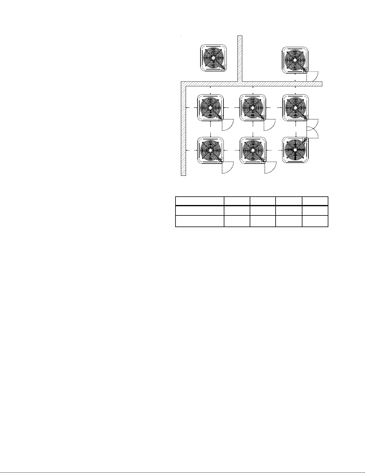
Special consideration must be given to location of the condensing unit(s) in regard to structures, obstructions, other
units, and any/all other factors that may interfere with air
circulation. Where possible, the top of the unit should be
completely unobstructed; however, if vertical conditions require placement beneath an obstruction there should be a
minimum of 60 in. [152 cm] between the top of the unit
and the obstruction(s). The specified dimensions meet re-
quirements for air circulation only. Consult all appropriate regulatory codes prior to determining final clearances.
Another important consideration in selecting a location for
the unit(s) is the angle to obstructions. Either side adjacent
the valves can be placed toward the structure provided the
side away from the structure maintains minimum service clearance. Corner installations are strongly discouraged.
DO NOT locate the unit:
– Directly under a vent termination for a gas appliance.
– Within 3 feet [1 m] of a clothes dryer vent.
– Where the refreezing of defrost water would create a
hazard.
– Where water may rise into the unit.
OK!
OK!
OK!
OK!
OK!
OK!
CKF**-*P* models are shipped with a nitrogen holding charge only.
4
Page 5
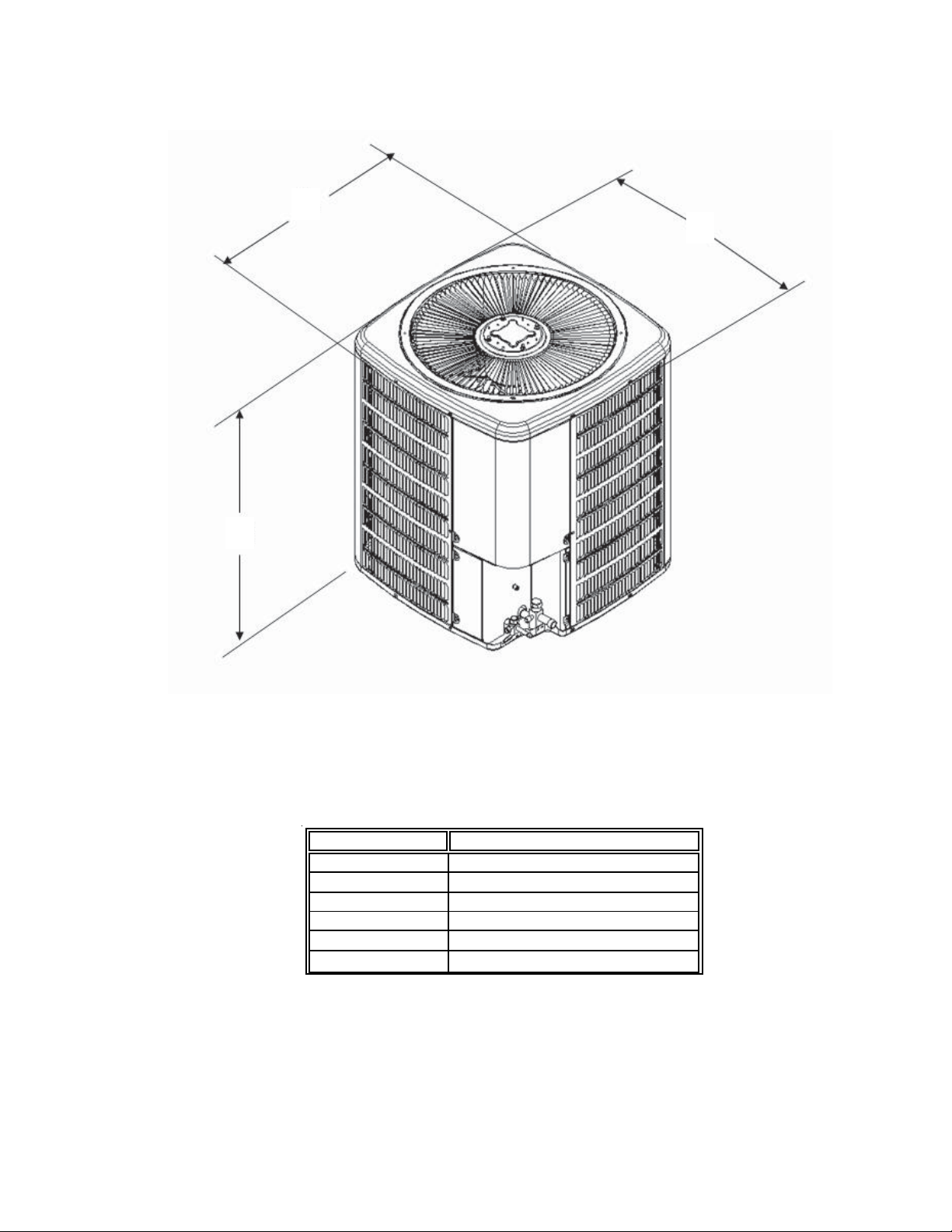
PRODUCT DESIGN
Dimensions
W
D
H
Mo d el Dim ensio ns - W x D x H
CKF 24-2* 26 " [6 60] x 26" [ 660] x 29¾ [7 56]
CKF 36-2* 26 " [6 60] x 26" [ 660] x 29¾ [7 56]
CKF 36-5* 26 " [6 60] x 26" [ 660] x 29¾ [7 56]
CKF 48-5* 29 " [7 37] x 29" [ 737] x 29¾ [7 56]
CKF 60-5* 29 " [7 37] x 29" [ 737] x 32¼ [8 19]
CKF 70-5* 29 " [7 37] x 29" [ 737] x 38¼ [9 72]
[ ] Designates metric equivalents
5
Page 6
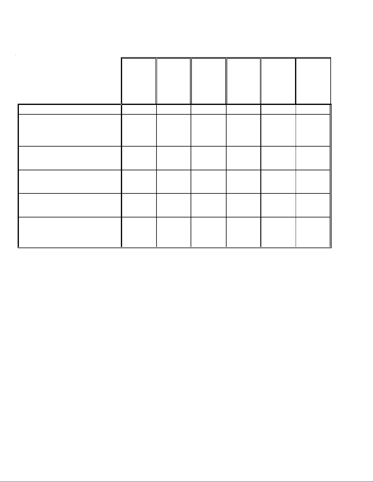
CONDENSING UNIT SPECIFICATIONS
(mm)
]
]
]
CKF24- 2*
CKF36-2*
CKF36-5*
CKF48-5*
CKF6 0-5*
CKF70- 5*
Cooling C apacity, BTUH/ k W 24600/7. 2 340 00/ 10. 0 34 000/1 0.0 4 4000/ 12. 9 55000/16.1 6 4000/1 8. 8
Compressor
R.L . Amps
L. R . Am ps
High Pressu r e Sw it c h-Open / Clo se
12.50 17.9 5.3 7.4 9 10.9
61.0 97.4 42.0 50.0 74.0 101.0
410/275 410/275 410/275 410/275 410/275 410/275
Condenser Fan Motor
Horsepower
F.L. Amps
1/41/41/41/41/41/3
0.90.90.80.80.81.2
Liq uid Line, Inches [mm] O.D.* 3/8 [9.6] 3/8 [9.6] 3/8 [9 .6] 3/8 [9.6] 3/8 [9.6] 3/8 [9.6 ]
Suct ion Line, Inches [mm ] O.D . * 3 /4 [19.1] 3/4 [19 .1 ] 7/8 [ 22. 3] 7/8 [22 .3] 7/8 [2 2.3] 7 /8 [22.3]
Ref rigerant Charge
88 89 89 113 121 153
Power Supply
Minimum Circuit Ampacity
Maximum Overcurrent Device
(1)
(2)
16.6 23.3 7.5 10 12 14.8
25 40 15 15 20 20
Elec trical Conduit Size
Power Supply (Inches) 1/2 or 3/ 4 1/2 or 3/4 1/ 2 or 3/ 4 1 /2 or 3/4 1/2 or 3/ 4 1/2 or 3/ 4
[13 or 20] [13 or 20] [13 or 20
[13 or 20] [13 or 20
[13 or 20
App rox im ate Sh ipping W eight (lb s- [kg] ) 18 0 [82 ] 1 84 [8 4] 184 [84 ] 19 1 [8 7] 210 [96] 2 28 [1 04]
[ ] Designates metric equiv al ents
1
Wir e s i z e s hou ld be det er m i ned in accor danc e w i th National Electr ical Codes. Extensive w i r e r uns will requi re l arger w i r e sizes.
2
May use fuses or HACR- ty pe c i r c uit breake r s of the sam e s i ze as noted.
NOTE: This data is provided as a guide, it is important to electrically connect the unit and properly size fuses/circuit
breakers and wires in accordance with all national and/or local electrical codes. Use copper wire only.
CKF**-*P* models are shipped with a nitrogen holding charge only.
6
Page 7
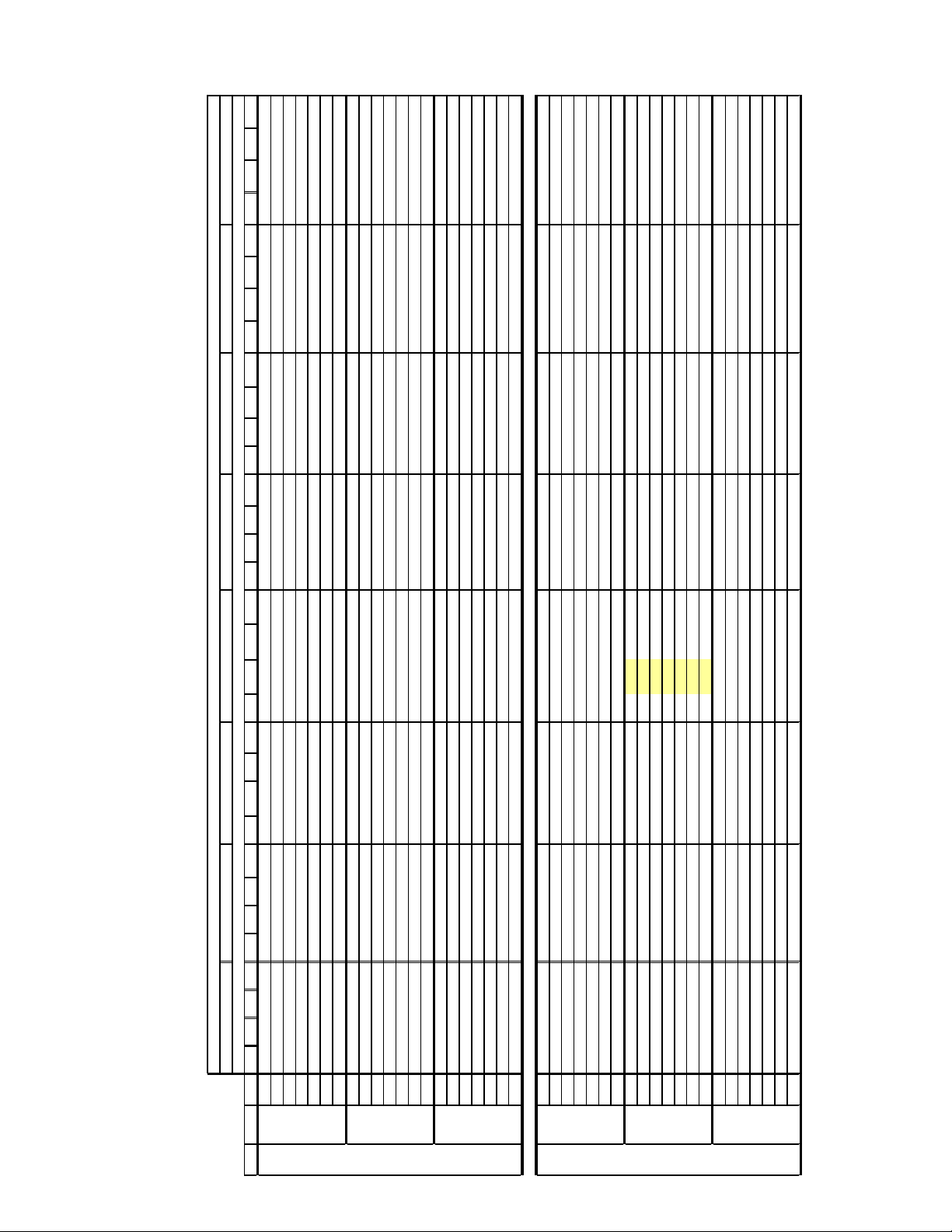
COOLING PERFORMANCE DATA
CKF24-2*
EXPANDE D P E RFORMANCE DATA
MO DEL: CKF2 4- 2 * / A24-0 0-2RA COOLING OPERATION
Outdoor Ambient Tem perature
Entering In door W et Bulb Temperature
65°F 75°F 85°F 95°F 105°F 115°F 118°F 125°F
DT 18 16 12 - 19 16 12 - 19 16 12 - 19 16 12 - 18 16 12 - 17 15 11 - 16 14 11 - 16 14 11 -
S/T 0.69 0.57 0.40 - 0.71 0.59 0.41 - 0.73 0.61 0.42 - 0.77 0.64 0.44 - 0.81 0.68 0.47 - 0.82 0.69 0.48 - 0.84 0.70 0.49 - 0.85 0.71 0.49 -
MBh 23.6 24.5 26.8 - 23.1 23.9 26.2 - 22.5 23.4 25.6 - 21.6 22.3 24.5 - 20.0 20.8 22.8 - 18.5 19.2 21.1 - 17.3 18.0 19.7 - 16.8 17.4 19.1 -
IDB Airflow 59 63 67 71 59 63 67 71 59 63 67 71 59 63 67 71 59 63 67 71 59 63 67 71 59 53 67 71 59 63 67 71
HI PR 155 167 177 - 174 188 198 - 198 213 225 - 226 243 257 - 254 273 289 - 281 302 319 - 298 321 339 - 305 329 347 -
AMPS 9.8 10.1 10.4 - 10.6 10.8 11.1 - 11.4 11.6 12.0 - 12.1 12.4 12.8 - 12.8 13.1 13.5 - 13.5 13.8 14.3 - 14.0 14.3 14.8 - 14.2 14.5 15.0 -
816 KW 2.03 2.08 2.15 - 2.20 2.25 2.32 - 2.35 2.40 2.48 - 2.50 2.55 2.64 - 2.60 2.66 2.76 - 2.70 2.76 2.86 - 2.74 2.80 2.90 - 2.75 2.82 2.91 -
DT 19 17 13 - 20 17 13 - 20 17 13 - 20 17 13 - 19 17 13 - 18 16 12 - 17 15 11 - 17 15 11 -
S/T 0.66 0.55 0.38 - 0.68 0.57 0.39 - 0.70 0.58 0.40 - 0.74 0.61 0.43 - 0.78 0.65 0.45 - 0.79 0.66 0.46 - 0.80 0.67 0.47 - 0.81 0.68 0.47 -
MBh 23.3 24.1 26.4 - 22.7 23.6 25.8 - 22.2 23.0 25.2 - 21.2 22.0 24.1 - 19.8 20.5 22.4 - 18.3 18.9 20.7 - 17.1 17.7 19.4 - 16.6 17.2 18.8 -
LO PR 56 60 65 - 59 63 69 - 61 65 71 - 65 69 75 - 68 72 79 - 70 74 81 - 71 76 83 - 72 76 83 -
HI PR 154 166 175 - 173 186 197 - 197 212 224 - 224 241 255 - 252 271 287 - 279 300 317 - 296 319 336 - 303 326 345 -
AMPS 9.8 10.0 10.3 - 10.5 10.7 11.1 - 11.3 11.6 11.9 - 12.0 12.3 12.7 - 12.7 13.0 13.4 - 13.4 13.7 14.2 - 13.9 14.2 14.7 - 14.1 14.4 14.9 -
70 730 KW 2.02 2.07 2.13 - 2.19 2.24 2.31 - 2.33 2.38 2.46 - 2.48 2.54 2.62 - 2.59 2.65 2.74 - 2.68 2.74 2.84 - 2.72 2.78 2.88 - 2.74 2.80 2.90 -
DT 20 17 13 - 20 17 13 - 20 17 13 - 20 18 13 - 20 17 13 - 19 16 12 - 18 15 12 - 17 15 11 -
S/T 0.63 0.53 0.36 - 0.65 0.55 0.38 - 0.67 0.56 0.39 - 0.70 0.59 0.41 - 0.75 0.62 0.43 - 0.75 0.63 0.44 - 0.77 0.64 0.45 - 0.78 0.65 0.45 -
MBh 22.1 22.9 25.1 - 21.6 22.4 24.5 - 21.1 21.9 23.9 - 20.2 20.9 22.9 - 18.8 19.5 21.3 - 17.4 18.0 19.7 - 16.2 16.8 18.4 - 15.7 16.3 17.9 -
LO PR 56 59 65 - 59 62 68 - 61 65 71 - 64 68 74 - 67 71 78 - 70 74 81 - 71 75 82 - 71 76 83 -
HI PR 151 163 172 - 170 183 193 - 193 208 219 - 220 236 250 - 247 266 281 - 273 294 310 - 290 312 330 - 297 320 338 -
AMPS 9.6 9.8 10.1 - 10.3 10.6 10.9 - 11.1 11.4 11.7 - 11.8 12.1 12.5 - 12.5 12.8 13.2 - 13.2 13.5 13.9 - 13.7 14.0 14.4 - 13.9 14.2 14.6 -
LO PR 54 58 63 - 58 61 67 - 60 64 69 - 63 67 73 - 66 70 76 - 68 72 79 - 69 74 80 - 70 74 81 -
644 KW 1.99 2.03 2.10 - 2.15 2.20 2.27 - 2.29 2.34 2.42 - 2.44 2.49 2.58 - 2.54 2.60 2.69 - 2.64 2.70 2.79 - 2.67 2.73 2.83 - 2.69 2.75 2.85 -
DT 21 19 16 11 21 20 16 11 21 20 16 11 22 20 16 11 21 20 16 11 20 18 15 10.4 19 17 14 9.9 19 17 14 9.7
S/T 0.78 0.70 0.53 0.3 0.81 0.72 0.55 0.4 0.83 0.74 0.56 0.4 0.87 0.78 0.59 0.4 0.93 0.83 0.63 0.4 0.94 0.84 0.63 0.4 0.95 0.85 0.65 0.4 0.96 0.86 0.65 0.4
MBh 24.0 24.7 26.8 28.7 23.5 24.2 26.1 28.1 22.9 23.6 25.5 27.4 21.9 22.6 24.4 26.2 20.4 21.0 22.7 24.4 18.9 19.4 21.0 22.6 17.6 18.1 19.6 21.1 17.1 17.6 19.1 20.5
HI PR 157 169 178 186.0 176 189 200 208.7 200 216 228 237.4 228 245 259 270.3 257 276 292 304.1 284 305 322 336.0 301 324 342 356.9 309 332 351 365.8
AMPS 9.9 10.1 10.4 10.8 10.7 10.9 11.2 11.6 11.5 11.7 12.1 12.5 12.2 12.5 12.9 13.3 12.9 13.2 13.6 14.1 13.6 14.0 14.4 14.9 14.1 14.4 14.9 15.4 14.3 14.6 15.1 15.6
816 KW 2.05 2.10 2.17 2.2 2.22 2.27 2.34 2.4 2.37 2.42 2.50 2.6 2.52 2.57 2.66 2.8 2.63 2.69 2.78 2.9 2.72 2.79 2.88 3.0 2.76 2.83 2.92 3.0 2.78 2.84 2.94 3.0
DT 22 21 17 12 23 21 17 12 23 21 17 12 23 21 17 12 22 21 17 12 21 19 16 10.9 20 18 15 10.4 20 18 15 10.2
S/T 0.75 0.67 0.51 0.3 0.78 0.69 0.52 0.3 0.79 0.71 0.54 0.3 0.84 0.75 0.57 0.4 0.89 0.79 0.60 0.4 0.90 0.80 0.61 0.4 0.91 0.82 0.62 0.4 0.92 0.82 0.62 0.4
MBh 23.7 24.4 26.4 28.3 23.1 23.8 25.8 27.6 22.6 23.2 25.2 27.0 21.6 22.2 24.1 25.8 20.1 20.7 22.4 24.0 18.6 19.1 20.7 22.2 17.4 17.9 19.4 20.8 16.8 17.3 18.8 20.2
LO PR 57 60 66 70.0 60 64 69 73.9 62 66 72 76. 8 65 69 76 8 0.7 68 73 79 84.6 71 75 82 87. 5 72 76 83 88.9 72 77 84 89.5
HI PR 156 168 177 184.7 175 188 199 207.3 199 214 226 235.7 227 244 257 268.5 255 274 290 302.0 282 303 320 333.7 299 322 340 354.4 306 330 348 363.2
AMPS 9.9 10.1 10.4 10.7 10.6 10.8 11.1 11.5 11.4 11.7 12.0 12.4 12.1 12.4 12.8 13.2 12.9 13.1 13.6 14.0 13.6 13.9 14.3 14.8 14.0 14.3 14.8 15.3 14.2 14.6 15.0 15.5
75 730 KW 2.04 2.08 2.15 2.2 2.21 2.25 2.33 2.4 2.35 2.40 2.49 2.6 2.50 2.56 2.65 2.7 2.61 2.67 2.76 2.9 2.71 2.77 2.86 3.0 2.74 2.81 2.91 3.0 2.76 2.82 2.92 3.0
DT 23 21 17 12 23 21 18 12 23 21 18 12 23 22 18 12 23 21 17 12 22 20 16 11.3 21 19 16 10.7 20 19 15 10.5
S/T 0.72 0.64 0.49 0.3 0.74 0.66 0.50 0.3 0.76 0.68 0.52 0.3 0.80 0.72 0.54 0.3 0.85 0.76 0.57 0.4 0.86 0.77 0.58 0.4 0.88 0.78 0.59 0.4 0.88 0.79 0.60 0.4
MBh 22.5 23.1 25.0 26.9 22.0 22.6 24.5 26.3 21.4 22.1 23.9 25.6 20.5 21.1 22.9 24.5 19.1 19.6 21.3 22.8 17.6 18.2 19.7 21.1 16.5 17.0 18.4 19.7 16.0 16.5 17.8 19.1
LO PR 56 60 65 69.5 59 63 69 73.4 62 66 72 76.3 65 69 75 80.1 68 72 79 84.0 70 75 82 86.9 71 76 83 88.3 72 76 83 88.9
HI PR 153 164 174 181.0 171 184 195 203.1 195 210 221 231.0 222 239 252 263.1 250 269 284 296.0 276 297 314 327.0 293 315 333 347.3 300 323 341 356.0
AMPS 9.7 9.9 10.2 10.6 10.4 10.6 11.0 11.3 11.2 11.5 11.8 12.2 11.9 12.2 12.6 13.0 12.6 12.9 13.3 13.8 13.3 13.6 14.1 14.6 13.8 14.1 14.5 15.1 14.0 14.3 14.7 15.3
LO PR 55 59 64 68.1 58 62 68 71.9 60 64 70 74. 8 63 68 74 7 8.5 67 71 77 82.3 69 73 80 85. 1 70 74 81 86.5 70 75 82 87.1
644 KW 2.01 2.05 2.12 2.2 2.17 2.22 2.29 2.4 2.31 2.36 2.44 2.5 2.46 2.52 2.60 2.7 2.57 2.63 2.72 2.8 2.66 2.72 2.81 2.9 2.70 2.76 2.85 3.0 2.71 2.78 2.87 3.0
Shaded area is ACCA (TVA) conditions IDB: Entering Indoor Dry Bulb Temperature KW= Total system pow er AMPS =outdoor unit amps (com p.+fan)
High and low pressures are measured at the liquid and suction service valves.
7
Page 8

COOLING PERFORMANCE DATA
CKF24-2*
Outdoor Ambient Tem perature
EXPANDE D P E RFORMANCE DATA
Entering In door W et Bulb Temperature
65 75 85 95 105 115 118°F 125°F
DT 24 23 20 16 24 23 20 16 24 23 20 16 24 23 20 16 23 23 20 16 22 21 18 14.8 20 20 18 14.1 20 20 17 13.8
S/T 0.86 0.80 0.65 0.5 0.89 0.83 0.68 0.5 0.91 0.85 0.69 0.5 0.96 0.90 0.73 0.5 1.00 0.95 0.78 0.6 1.00 0.96 0.78 0.6 1.00 0.99 0.80 0.6 1.00 1.00 0.81 0.6
MO DEL: CKF2 4- 2 * / A24-0 0-2RA COOLING OPERATION
MBh 24.4 25.0 26.7 28.5 23.9 24.4 26.1 27.9 23.3 23.8 25.5 27.2 22.3 22.8 24.4 26.0 20.8 21.2 22.7 24.2 19.2 19.6 20.9 22.4 17.9 18.3 19.6 20.9 17.4 17.8 19.0 20.3
IDB*Airflow 59636771596367 71 59 63 67 71 59 63 67 71 59636771 5963 67 71 59 53 67 71 59 63 67 71
HI PR 159 171 180 187.9 178 191 202 210.8 202 218 230 239.8 230 248 262 273.1 259 279 295 307.2 286 308 325 339.4 304 327 346 360.5 312 335 354 369.5
AMPS 10.0 10.2 10.5 10.9 10.7 11.0 11.3 11.7 11.6 11.8 12.2 12.6 12.3 12.6 13.0 13.4 13.0 13.3 13.8 14.2 13.8 14.1 14.5 15.0 14.2 14.6 15.0 15.6 14.4 14.8 15.215.8
816 KW 2.07 2.11 2.18 2.3 2.24 2.29 2.36 2.4 2.39 2.44 2.52 2.6 2.54 2.60 2.69 2.8 2.65 2.71 2.81 2.9 2.75 2.81 2.91 3.0 2.79 2.85 2.95 3.1 2.80 2.87 2.97 3.1
8
DT 25 24 21 17 25 24 21 17 25 24 21 17 25 24 21 17 25 24 21 17 23 22 19 15.6 22 21 19 14.8 22 21 18 14.5
S/T 0.82 0.77 0.63 0.5 0.85 0.80 0.65 0.5 0.87 0.82 0.67 0.5 0.92 0.86 0.70 0.5 0.97 0.91 0.74 0.6 0.98 0.92 0.75 0.6 0.99 0.94 0.77 0.6 1.00 0.95 0.77 0.6
MBh 24.1 24.6 26.3 28.1 23.5 24.0 25.7 27.5 23.0 23.5 25.1 26.8 22.0 22.5 24.0 25.7 20.4 20.9 22.3 23.9 18.9 19.3 20.6 22.1 17.7 18.1 19.3 20.6 17.1 17.5 18.7 20.0
LO PR 57 61 66 70.7 60 64 70 74.7 63 67 73 77. 6 66 70 77 8 1.5 69 73 80 85.4 71 76 83 88. 4 73 77 84 89.8 73 78 85 90.4
HI PR 157 169 179 186.6 177 190 201 209.4 201 216 228 238.1 229 246 260 271.2 257 277 293 305.1 284 306 323 337.1 302 325 343 358.0 310 333 352 366.9
AMPS 10.0 10.2 10.5 10.8 10.7 10.9 11.2 11.6 11.5 11.8 12.1 12.5 12.2 12.5 12.9 13.4 13.0 13.3 13.7 14.2 13.7 14.0 14.4 14.9 14.1 14.5 14.9 15.5 14.3 14.7 15.1 15.7
80 730 KW 2.06 2.10 2.17 2.2 2.22 2.27 2.35 2.4 2.37 2.43 2.51 2.6 2.52 2.58 2.67 2.8 2.63 2.70 2.79 2.9 2.73 2.79 2.89 3.0 2.77 2.83 2.93 3.0 2.78 2.85 2.95 3.1
DT 26 25 21 17 26 25 22 17 26 25 22 17 26 25 22 17 26 25 22 17 24 23 20 16 23 22 19 15.3 23 22 19 15.0
S/T 0.79 0.74 0.60 0.4 0.81 0.76 0.62 0.5 0.83 0.78 0.64 0.5 0.88 0.82 0.67 0.5 0.93 0.87 0.71 0.5 0.94 0.88 0.72 0.5 0.96 0.90 0.73 0.5 0.97 0.91 0.74 0.6
MBh 22.9 23.4 25.0 26.7 22.3 22.8 24.4 26.1 21.8 22.3 23.8 25.5 20.9 21.3 22.8 24.4 19.4 19.8 21.2 22.7 18.0 18.4 19.6 21.0 16.8 17.2 18.3 19.6 16.3 16.6 17.8 19.0
LO PR 57 60 66 70.2 60 64 70 74.1 62 66 72 77.1 65 70 76 80.9 69 73 80 84.8 71 75 82 87.7 72 77 84 89.2 73 77 84 89.8
HI PR 154 166 175 182.8 173 186 197 205.2 197 212 224 233.3 224 241 255 265.8 252 271 287 299.0 279 300 317 330.3 296 319 336 350.8 303 326 345 359.6
AMPS 9.8 10.0 10.3 10.6 10.5 10.7 11.1 11.4 11.3 11.6 11.9 12.3 12.0 12.3 12.7 13.1 12.7 13.0 13.4 13.9 13.4 13.7 14.2 14.7 13.9 14.2 14.7 15.2 14.1 14.4 14.9 15.4
LO PR 56 59 65 68.8 59 62 68 72.7 61 65 71 75. 5 64 68 74 7 9.3 67 71 78 83.1 70 74 81 86. 0 71 75 82 87.4 71 76 83 88.0
644 KW 2.02 2.07 2.13 2.2 2.19 2.24 2.31 2.4 2.33 2.38 2.46 2.5 2.48 2.54 2.62 2.7 2.59 2.65 2.74 2.8 2.68 2.74 2.84 2.9 2.72 2.78 2.88 3.0 2.74 2.80 2.90 3.0
DT 25 25 23 20 25 25 24 21 26 25 24 21 26 25 24 21 24 24 24 20 22 22 22 19.0 21 21 21 18.2 20 20 21 17.8
S/T 0.90 0.87 0.78 0.6 0.93 0.90 0.81 0.7 0.95 0.92 0.83 0.7 1.00 0.97 0.87 0.7 1.00 1.00 0.93 0.8 1.00 1.00 0.94 0.8 1.00 1.00 0.96 0.8 1.00 1.00 0.96 0.8
MBh 24.9 25.3 26.5 28.3 24.3 24.8 25.9 27.7 23.7 24.2 25.3 27.0 22.7 23.1 24.2 25.9 21.1 21.5 22.5 24.0 19.5 19.9 20.8 22.2 18.3 18.6 19.5 20.8 17.7 18.1 18.9 20.2
HI PR 160 172 182 189.8 180 193 204 212.9 204 220 232 242.2 233 250 264 275.8 262 282 297 310.3 289 311 329 342.8 307 331 349 364.1 315 339 358 373.2
AMPS 10.1 10.3 10.6 11.0 10.8 11.1 11.4 11.8 11.7 11.9 12.3 12.7 12.4 12.7 13.1 13.5 13.2 13.5 13.9 14.4 13.9 14.2 14.6 15.2 14.4 14.7 15.2 15.7 14.6 14.9 15.415.9
816 KW 2.09 2.13 2.20 2.3 2.26 2.31 2.38 2.5 2.41 2.46 2.54 2.6 2.56 2.62 2.71 2.8 2.67 2.74 2.83 2.9 2.77 2.84 2.93 3.0 2.81 2.88 2.98 3.1 2.83 2.89 2.99 3.1
DT 27 26 25 21 27 26 25 22 27 26 25 22 27 27 25 22 26 26 25 21 24 25 23 20.1 23 23 22 19.1 22 22 22 18.7
S/T 0.86 0.83 0.75 0.6 0.89 0.86 0.78 0.6 0.91 0.88 0.80 0.6 0.96 0.93 0.84 0.7 1.00 0.98 0.89 0.7 1.00 0.99 0.90 0.7 1.00 1.00 0.92 0.7 1.00 1.00 0.92 0.7
MBh 24.5 25.0 26.1 27.9 23.9 24.4 25.6 27.3 23.4 23.8 25.0 26.6 22.4 22.8 23.9 25.5 20.8 21.2 22.2 23.7 19.2 19.6 20.5 21.9 18.0 18.3 19.2 20.5 17.4 17.8 18.6 19.9
LO PR 58 61 67 71.4 61 65 71 75.4 63 67 74 78. 4 67 71 77 8 2.3 70 74 81 86.3 72 77 84 89. 2 73 78 85 90.7 74 79 86 91.3
HI PR 159 171 181 188.4 178 192 203 211.4 203 218 231 240.5 231 249 263 273.9 260 280 295 308.1 287 309 326 340.4 305 328 347 361.5 313 336 355 370.6
AMPS 10.0 10.3 10.6 10.9 10.8 11.0 11.3 11.7 11.6 11.9 12.2 12.7 12.3 12.6 13.0 13.5 13.1 13.4 13.8 14.3 13.8 14.1 14.6 15.1 14.3 14.6 15.1 15.6 14.5 14.8 15.315.8
85 730 KW 2.07 2.12 2.19 2.3 2.24 2.29 2.37 2.5 2.39 2.45 2.53 2.6 2.55 2.60 2.69 2.8 2.66 2.72 2.81 2.9 2.75 2.82 2.92 3.0 2.79 2.86 2.96 3.1 2.81 2.87 2.97 3.1
DT 27 27 25 22 28 27 26 22 28 27 26 22 28 27 26 22 28 27 26 22 26 25 24 20.7 24 24 23 19.7 24 24 22 19.3
S/T 0.82 0.80 0.72 0.6 0.85 0.82 0.74 0.6 0.88 0.84 0.76 0.6 0.92 0.89 0.80 0.7 0.98 0.94 0.85 0.7 0.99 0.95 0.86 0.7 1.00 0.97 0.88 0.7 1.00 0.98 0.88 0.7
MBh 23.3 23.7 24.8 26.5 22.7 23.2 24.3 25.9 22.2 22.6 23.7 25.3 21.2 21.7 22.7 24.2 19.8 20.1 21.1 22.5 18.3 18.6 19.5 20.8 17.1 17.4 18.2 19.5 16.6 16.9 17.7 18.9
LO PR 57 61 67 70.9 61 64 70 74.9 63 67 73 77. 8 66 70 77 8 1.7 69 74 80 85.7 72 76 83 88. 6 73 77 85 90.0 73 78 85 90.7
HI PR 156 168 177 184.7 175 188 199 207.2 199 214 226 235.7 226 244 257 268.4 255 274 290 302.0 281 303 320 333.6 299 322 340 354.3 306 330 348 363.2
AMPS 9.9 10.1 10.4 10.7 10.6 10.8 11.1 11.5 11.4 11.7 12.0 12.4 12.1 12.4 12.8 13.2 12.9 13.1 13.5 14.0 13.6 13.9 14.3 14.8 14.0 14.3 14.8 15.3 14.2 14.6 15.0 15.5
LO PR 56 60 65 69.5 59 63 69 73.4 62 66 72 76. 3 65 69 75 8 0.1 68 72 79 84.0 70 75 82 86. 8 71 76 83 88.2 72 76 83 88.8
644 KW 2.04 2.08 2.15 2.2 2.20 2.25 2.33 2.4 2.35 2.40 2.49 2.6 2.50 2.56 2.65 2.7 2.61 2.67 2.76 2.9 2.71 2.77 2.86 3.0 2.74 2.81 2.90 3.0 2.76 2.82 2.92 3.0
Shaded area is AHRI Rating Conditions IDB: Entering Indoor D ry Bulb Tem perature KW=Total system power AMPS=outdoor unit amps (comp.+fan)
High and low pressures are measured at the liquid and suction service valves.
Page 9

COOLING PERFORMANCE DATA
CKF36-2*
EXP ANDED PERFORMANCE DATA
Outdoo r Ambient Temperature
Entering Indoor Wet Bulb Temperature
65°F 75°F 85°F 95°F 105°F 115°F 118°F 125°F
DT 17 15 11 - 17 15 11 - 18 15 12 - 18 15 12 - 17 15 11 - 16 14 11 - 15 13 10 - 15 13 10 -
S/T 0.71 0.59 0.41 - 0.74 0.62 0.43 - 0.76 0.63 0.44 - 0.80 0.66 0.46 - 0.84 0.70 0.49 - 0.85 0.71 0.49 - 0.87 0.73 0.50 - 0.88 0.73 0.51 -
MBh 32.5 33.6 36.9 - 31.7 32.9 36.0 - 31.0 32.1 35.2 - 29.6 30.7 33.7 - 27.6 28.6 31.3 - 25.5 26.4 28.9 - 23.8 24.7 27.1 - 23.1 24.0 26.3 -
MODEL: CKF36-2* / A 36-00-2 COOLING OPERATION
IDB Airflow 59 63 67 71 59 63 67 71 59 63 67 71 59 63 67 71 59 63 67 71 59 63 67 71 59 53 67 71 59 63 67 71
HI PR 161 174 183 - 181 195 206 - 206 222 234 - 234 252 266 - 264 284 300 - 291 314 331 - 310 333 352 - 317 341 361 -
AMPS 14.8 15.1 15.6 - 15.9 16.3 16.8 - 17.3 17.7 18.2 - 18.4 18.9 19.5 - 19.6 20.0 20.7 - 20.7 21.2 21.9 - 21.5 22.0 22.7 - 21.8 22.3 23.0 -
1229 KW 2.67 2.73 2.83 - 2.90 2.97 3.07 - 3.10 3.18 3.29 - 3.31 3.39 3.51 - 3.46 3.54 3.67 - 3.59 3.68 3.81 - 3.64 3.73 3.86 - 3.66 3.75 3.89 -
DT 18 16 12 - 18 16 12 - 18 16 12 - 19 16 12 - 18 16 12 - 17 15 11 - 16 14 11 - 16 14 11 -
S/T 0.68 0.57 0.39 - 0.71 0.59 0.41 - 0.72 0.60 0.42 - 0.76 0.64 0.44 - 0.81 0.67 0.47 - 0.82 0.68 0.47 - 0.83 0.70 0.48 - 0.84 0.70 0.49 -
MBh 32.0 33.1 36.3 - 31.2 32.4 35.5 - 30.5 31.6 34.7 - 29.2 30.3 33.2 - 27.2 28.2 30.8 - 25.1 26.0 28.5 - 23.5 24.3 26.7 - 22.8 23.6 25.9 -
LO PR 55 58 63 - 58 61 67 - 60 64 70 - 63 67 73 - 66 70 77 - 68 73 79 - 69 74 80 - 70 74 81 -
HI PR 160 172 182 - 180 193 204 - 204 220 232 - 233 251 265 - 262 282 298 - 289 311 329 - 307 331 349 - 315 339 358 -
AMPS 14.7 15.0 15.5 - 15.8 16.2 16.7 - 17.1 17.6 18.1 - 18.3 18.7 19.3 - 19.4 19.9 20.6 - 20.6 21.1 21.8 - 21.3 21.8 22.6 - 21.6 22.2 22.9 -
70 1100 KW 2.66 2.72 2.81 - 2.88 2.95 3.05 - 3.08 3.16 3.27 - 3.29 3.37 3.49 - 3.44 3.52 3.65 - 3.57 3.65 3 .78 - 3.62 3.71 3.84 - 3.64 3.73 3.86 -
DT 19 16 12 - 19 16 12 - 19 16 13 - 19 17 13 - 19 16 12 - 18 15 12 - 17 15 11 - 16 14 11 -
S/T 0.65 0.55 0.38 - 0.68 0.57 0.39 - 0.69 0.58 0.40 - 0.73 0.61 0.42 - 0.77 0.65 0.45 - 0.78 0.65 0.45 - 0.80 0.67 0.46 - 0.80 0.67 0.47 -
MBh 30.4 31.5 34.5 - 29.7 30.8 33.7 - 29.0 30.1 32.9 - 27.7 28.8 31.5 - 25.8 26.7 29.3 - 23.9 24.7 27.1 - 22.3 23.1 25.3 - 21.6 22.4 24.6 -
LO PR 54 58 63 - 57 61 66 - 59 63 69 - 62 66 73 - 65 70 76 - 68 72 79 - 69 73 80 - 69 74 80 -
HI PR 157 169 178 - 176 190 200 - 200 216 228 - 228 246 259 - 257 276 292 - 284 305 322 - 301 324 342 - 309 332 351 -
AMPS 14.4 14.8 15.2 - 15.5 15.9 16.4 - 16.8 17.2 17.8 - 18.0 18.4 19.0 - 19.1 19.6 20.2 - 20.2 20.7 21.4 - 20.9 21.4 22.1 - 21.2 21.8 22.5 -
LO PR 53 56 62 - 56 60 65 - 58 62 68 - 61 65 71 - 64 68 74 - 66 71 77 - 67 72 78 - 68 72 79 -
971 KW 2.61 2.67 2.76 - 2.83 2.90 3.00 - 3.03 3.10 3.21 - 3.23 3.31 3.42 - 3.38 3.46 3.58 - 3.50 3.59 3.72 - 3.55 3.64 3.77 - 3.58 3.66 3.79 -
DT 20 18 15 10 20 19 15 11 20 19 15 11 20 19 15 11 20 19 15 10 19 17 14 9.8 18 16 14 9.3 18 16 13 9.1
S/T 0.81 0.72 0.55 0.4 0.84 0.75 0.57 0.4 0.86 0.77 0.58 0.4 0.90 0.81 0.61 0.4 0.96 0.86 0.65 0.4 0.97 0.87 0.66 0.4 0.99 0.88 0.67 0.4 1.00 0.89 0.67 0.4
MBh 33.0 34.0 36.8 39.5 32.3 33.2 35.9 38.6 31.5 32.4 35.1 37.7 30.1 31.0 33.6 36.1 28.0 28.9 31.2 33.5 25.9 26.7 2 8.9 31.0 24.2 25.0 27.0 29.0 23.5 24.2 26.2 28.1
HI PR 163 175 185 193.2 183 197 208 216.7 208 224 236 246.5 237 255 269 280.7 266 287 303 315.8 294 317 335 349.0 313 336 355 370.6 320 345 364 379.8
AMPS 14.9 15.2 15.7 16.3 16.1 16.4 17.0 17.6 17.4 17.8 18.4 19.1 18.6 19.0 19.6 20.4 19.7 20.2 20.9 21.7 20.9 21.4 22.1 22.9 21.7 22.2 22.9 23.8 22.0 22.5 23.324.1
1229 KW 2.70 2.76 2.85 3.0 2.93 3.00 3.10 3.2 3.13 3.20 3.32 3.4 3.34 3.42 3.54 3.7 3.49 3.58 3.70 3.8 3.62 3.71 3.84 4.0 3.68 3.76 3.90 4.0 3.70 3.79 3.92 4.1
DT 21 19 16 11 21 20 16 11 21 20 16 11 21 20 16 11 21 20 16 11 20 18 15 10.3 19 17 14 9.8 18 17 14 9.6
S/T 0.78 0.69 0.52 0.3 0.80 0.72 0.54 0.3 0.82 0.74 0.56 0.4 0.87 0.77 0.59 0.4 0.92 0.82 0.62 0.4 0.93 0.83 0.63 0.4 0.95 0.85 0.64 0.4 0.95 0.85 0.65 0.4
MBh 32.5 33.5 36.2 38.9 31.8 32.7 35.4 38.0 31.0 32.0 34.6 37.1 29.7 30.6 33.1 35.5 27.6 28.4 30.8 33.0 25.5 26.3 28.5 30.6 23.9 24.6 26.6 28.6 23.2 23.9 25.8 27.7
LO PR 55 59 64 68.1 58 62 68 72.0 60 64 70 74.8 64 68 74 78.6 67 71 77 82.3 69 73 80 85.2 70 74 81 86.5 70 75 82 87.1
HI PR 162 174 184 191.8 182 195 206 215.2 207 222 235 244.8 235 253 267 278.8 265 285 301 313.6 292 315 332 346.5 310 334 353 368.0 318 342 362 377.2
AMPS 14.8 15.1 15.6 16.2 16.0 16.3 16.9 17.5 17.3 17.7 18.3 19.0 18.5 18.9 19.5 20.2 19.6 20.1 20.8 21.5 20.8 21.3 22.0 22.8 21.5 22.0 22.8 23.6 21.8 22.4 23.1 24.0
75 1100 KW 2.68 2.74 2.84 2.9 2.91 2.98 3.08 3.2 3.11 3.18 3.30 3.4 3.32 3.40 3.52 3.6 3.47 3.55 3.68 3.8 3.60 3.69 3.82 4.0 3.65 3.74 3.87 4.0 3.67 3.76 3.90 4.0
DT 22 20 16 11 22 20 17 11 22 20 17 11 22 20 17 12 22 20 16 11 20 19 15 10.6 19 18 15 10.1 19 18 14 9.9
S/T 0.74 0.66 0.50 0.3 0.77 0.69 0.52 0.3 0.79 0.71 0.53 0.3 0.83 0.74 0.56 0.4 0.88 0.79 0.60 0.4 0.89 0.79 0.60 0.4 0.91 0.81 0.61 0.4 0.91 0.82 0.62 0.4
MBh 30.9 31.8 34.4 37.0 30.2 31.1 33.6 36.1 29.5 30.4 32.9 35.3 28.2 29.1 31.4 33.7 26.2 27.0 29.2 31.4 24.3 25.0 2 7.0 29.0 22.7 23.4 25.3 27.1 22.0 22.7 24.5 26.3
LO PR 55 58 64 67.6 58 61 67 71.5 60 64 70 74.3 63 67 73 78.0 66 70 77 81.8 68 73 79 84.6 69 74 81 85.9 70 74 81 86.5
HI PR 159 171 180 188.0 178 192 202 210.9 202 218 230 239.9 231 248 262 273.2 259 279 295 307.4 287 308 326 339.6 304 327 346 360.6 312 336 354 369.7
AMPS 14.5 14.9 15.4 15.9 15.7 16.0 16.6 17.2 17.0 17.4 18.0 18.6 18.1 18.6 19.2 19.9 19.3 19.7 20.4 21.1 20.4 20.9 21.6 22.4 21.1 21.6 22.4 23.2 21.4 22.0 22.723.5
LO PR 54 57 62 66.3 57 60 66 70.0 59 63 68 72.8 62 66 72 76.5 65 69 75 80.1 67 71 78 82.9 68 72 79 84.2 69 73 80 84.8
971 KW 2.63 2.69 2.79 2.9 2.86 2.92 3.03 3.1 3.06 3.13 3.24 3.4 3.26 3.34 3.45 3.6 3.41 3.49 3.61 3.7 3.54 3.62 3.75 3.9 3.59 3.67 3.80 3.9 3.61 3.70 3.83 4.0
Shaded area is ACC A (TVA) condi t ions IDB: Entering Indoor Dry Bulb Temperature KW=Total system power AMPS=outdoor unit amps (com p.+fan)
Hi gh and low pressures are measured at the liqu id and suction service valves.
9
Page 10

COOLING PERFORMANCE DATA
CKF36-2*
10
EXP ANDED PERFORMANCE DATA
Outdoo r Ambient Temperature
Entering Indoor Wet Bulb Temperature
65 75 85 95 105 115 118°F 125°F
DT 22 21 19 15 23 22 19 15 23 22 19 15 23 22 19 15 21 22 19 15 20 20 17 14.0 18 19 17 13.3 18 18 16 13.0
S/T 0.89 0.83 0.68 0.5 0.92 0.86 0.70 0.5 0.94 0.88 0.72 0.5 1.00 0.93 0.76 0.6 1.00 1.00 0.80 0.6 1.00 1.00 0.81 0.6 1.00 1.00 0.83 0.6 1.00 1.00 0.83 0.6
MBh 33.6 34.3 36.7 39.2 32.8 33.5 35.8 38.3 32.1 32.8 35.0 37.4 30.7 31.4 33.5 35.8 28.5 29.2 31.2 33.3 26.4 27.0 2 8.8 30.8 24.7 25.2 26.9 28.8 23.9 24.5 26.1 27.9
MODEL: CKF36-2* / A 36-00-2 COOLING OPERATION
IDB*Airflow 596367715963677159 63 67 71 59 63 67 71 59636771596367 71 59 53 67 71 59 63 67 71
HI PR 165 177 187 195.1 185 199 210 218.9 210 226 239 249.0 239 257 272 283.6 269 290 306 319.0 297 320 338 352.5 316 340 359 374.3 324 348 368 383.7
AMPS 15.0 15.4 15.9 16.4 16.2 16.6 17.1 17.7 17.6 18.0 18.6 19.3 18.7 19.2 19.8 20.6 19.9 20.4 21.1 21.9 21.1 21.6 22.3 23.2 21.9 22.4 23.1 24.0 22.2 22.7 23.524.4
1229 KW 2.72 2.78 2.88 3.0 2.95 3.02 3.13 3.2 3.16 3.23 3.35 3.5 3.37 3.45 3.57 3.7 3.52 3.61 3.74 3.9 3.66 3.74 3.88 4.0 3.71 3.80 3.93 4.1 3.73 3.82 3.96 4.1
DT 24 23 20 16 24 23 20 16 24 23 20 16 24 23 20 16 23 23 20 16 22 21 18 14.7 20 20 18 14.0 20 20 17 13.7
S/T 0.85 0.80 0.65 0.5 0.88 0.83 0.67 0.5 0.90 0.85 0.69 0.5 0.95 0.89 0.73 0.5 1.00 0.94 0.77 0.6 1.00 0.95 0.78 0.6 1.00 0.97 0.79 0.6 1.00 0.98 0.80 0.6
MBh 33.1 33.8 36.1 38.6 32.3 33.1 35.3 37.7 31.6 32.3 34.5 36.9 30.2 30.9 33.0 35.3 28.1 28.7 30.7 32.8 26.0 26.6 28.4 30.3 24.3 24.8 26.5 28.4 23.6 24.1 25.7 27.5
LO PR 56 59 65 68.8 59 63 68 72.7 61 65 71 75.6 64 68 75 79.4 67 72 78 83.2 70 74 81 86.0 71 75 82 87.4 71 76 83 88.0
HI PR 163 176 186 193.7 183 197 208 217.4 209 224 237 247.3 238 256 270 281.6 267 288 304 316.8 295 318 336 350.0 314 338 356 371.7 321 346 365 381.0
AMPS 14.9 15.3 15.8 16.3 16.1 16.5 17.0 17.6 17.5 17.9 18.5 19.1 18.6 19.1 19.7 20.4 19.8 20.3 20.9 21.7 21.0 21.5 22.2 23.0 21.7 22.2 23.0 23.8 22.0 22.6 23.3 24.2
80 1100 KW 2.70 2.77 2.86 3.0 2.93 3.00 3.11 3.2 3.14 3.21 3.33 3.4 3.35 3.43 3.55 3.7 3.50 3.59 3.71 3.8 3.63 3.72 3.85 4.0 3.69 3.77 3.91 4.1 3.71 3.80 3.93 4.1
DT 24 23 20 16 25 24 20 16 25 24 20 16 25 24 21 16 24 23 20 16 23 22 19 15 22 21 18 14.5 21 20 18 14.2
S/T 0.81 0.76 0.62 0.5 0.84 0.79 0.64 0.5 0.86 0.81 0.66 0.5 0.91 0.85 0.69 0.5 0.96 0.90 0.74 0.6 0.97 0.91 0.74 0.6 0.99 0.93 0.76 0.6 1.00 0.94 0.77 0.6
MBh 31.4 32.1 34.3 36.7 30.7 31.4 33.5 35.9 30.0 30.7 32.8 35.0 28.7 29.3 31.4 33.5 26.7 27.3 29.2 31.2 24.7 25.2 2 7.0 28.8 23.1 23.6 25.2 26.9 22.4 22.9 24.5 26.1
LO PR 55 59 64 68.3 58 62 68 72.2 61 65 70 75.0 64 68 74 78.8 67 71 78 82.6 69 73 80 85.4 70 75 82 86.8 71 75 82 87.4
HI PR 160 172 182 189.9 180 193 204 213.1 204 220 232 242.3 233 251 265 276.0 262 282 298 310.5 289 311 329 343.0 307 331 349 364.3 315 339 358 373.4
AMPS 14.7 15.0 15.5 16.0 15.8 16.2 16.7 17.3 17.1 17.6 18.1 18.8 18.3 18.7 19.3 20.1 19.4 19.9 20.6 21.3 20.6 21.1 21.8 22.6 21.3 21.8 22.6 23.4 21.6 22.2 22.923.8
LO PR 54 58 63 67.0 57 61 66 70.7 59 63 69 73.5 62 66 73 77.2 65 70 76 80.9 68 72 79 83.7 69 73 80 85.1 69 74 80 85.7
971 KW 2.66 2.72 2.81 2.9 2.88 2.95 3.05 3.2 3.08 3.16 3.27 3.4 3.29 3.37 3.49 3.6 3.44 3.52 3.65 3.8 3.57 3.65 3.78 3.9 3.62 3.71 3.84 4.0 3.64 3.73 3.86 4.0
DT 24 23 22 19 24 24 22 19 24 24 22 19 23 24 23 20 22 22 22 19 20 20 21 18.0 19 19 20 17.2 18 19 19 16.8
S/T 0.93 0.90 0.81 0.7 0.96 0.93 0.84 0.7 0.99 0.95 0.86 0.7 1.00 1.00 0.91 0.7 1.00 1.00 0.96 0.8 1.00 1.00 0.97 0.8 1.00 1.00 0.99 0.8 1.00 1.00 1.00 0.8
MBh 34.2 34.8 36.5 38.9 33.4 34.0 35.7 38.0 32.6 33.3 34.8 37.2 31.2 31.8 33.3 35.6 29.0 29.6 31.0 33.1 26.8 27.4 2 8.7 30.6 25.1 25.6 26.8 28.6 24.3 24.8 26.0 27.7
HI PR 166 179 189 197.1 187 201 212 221.1 212 228 241 251.5 242 260 275 286.4 272 293 309 322.2 300 323 341 356.0 319 343 362 378.1 327 352 372 387.5
AMPS 15.2 15.5 16.0 16.6 16.3 16.7 17.3 17.9 17.7 18.1 18.7 19.4 18.9 19.4 20.0 20.7 20.1 20.6 21.3 22.1 21.3 21.8 22.5 23.4 22.1 22.6 23.3 24.2 22.4 22.9 23.724.6
1229 KW 2.74 2.81 2.90 3.0 2.98 3.05 3.16 3.3 3.19 3.26 3.38 3.5 3.40 3.48 3.60 3.7 3.56 3.64 3.77 3.9 3.69 3.78 3.91 4.1 3.74 3.83 3.97 4.1 3.77 3.86 4.00 4.1
DT 25 25 23 20 25 25 24 20 25 25 24 20 26 25 24 21 24 24 23 20 22 23 22 19.0 21 21 21 18.1 20 20 20 17.7
S/T 0.89 0.86 0.78 0.6 0.92 0.89 0.80 0.7 0.95 0.91 0.82 0.7 1.00 0.96 0.87 0.7 1.00 1.00 0.92 0.7 1.00 1.00 0.93 0.8 1.00 1.00 0.95 0.8 1.00 1.00 0.96 0.8
MBh 33.7 34.3 36.0 38.4 32.9 33.5 35.1 37.5 32.1 32.8 34.3 36.6 30.8 31.4 32.8 35.0 28.6 29.2 30.5 32.6 26.5 27.0 2 8.2 30.1 24.7 25.2 26.4 28.2 24.0 24.5 25.6 27.3
LO PR 56 60 65 69.5 59 63 69 73.4 62 66 72 76.3 65 69 75 80.2 68 72 79 84.0 70 75 82 86.9 71 76 83 88.3 72 76 83 88.9
HI PR 165 178 188 195.7 185 199 211 219.6 211 227 239 249.7 240 258 273 284.4 270 291 307 320.0 298 321 339 353.5 317 341 360 375.4 325 349 369 384.8
AMPS 15.1 15.4 15.9 16.5 16.2 16.6 17.2 17.8 17.6 18.0 18.6 19.3 18.8 19.2 19.9 20.6 20.0 20.5 21.1 21.9 21.1 21.7 22.4 23.2 21.9 22.4 23.2 24.1 22.2 22.8 23.524.4
85 1100 KW 2.73 2.79 2.89 3.0 2.96 3.03 3.14 3.2 3.17 3.24 3.36 3.5 3.38 3.46 3.58 3.7 3.53 3.62 3.75 3.9 3.67 3.75 3.89 4.0 3.72 3.81 3.95 4.1 3.74 3.83 3.97 4.1
DT 26 25 24 21 26 26 24 21 26 26 24 21 26 26 25 21 26 26 24 21 24 24 23 19.6 22 23 22 18.7 22 22 21 18.3
S/T 0.85 0.82 0.74 0.6 0.88 0.85 0.77 0.6 0.91 0.87 0.79 0.6 0.95 0.92 0.83 0.7 1.00 0.98 0.88 0.7 1.00 0.99 0.89 0.7 1.00 1.00 0.91 0.7 1.00 1.00 0.92 0.7
MBh 32.0 32.6 34.2 36.4 31.3 31.9 33.4 35.6 30.5 31.1 32.6 34.8 29.2 29.8 31.2 33.3 27.2 27.7 29.0 30.9 25.1 25.6 2 6.8 28.6 23.5 23.9 25.1 26.8 22.8 23.2 24.3 26.0
LO PR 56 59 65 69.0 59 63 68 72.9 61 65 71 75.8 64 68 75 79.6 67 72 78 83.4 70 74 81 86.3 71 75 82 87.7 71 76 83 88.3
HI PR 162 174 184 191.8 182 195 206 215.2 206 222 235 244.7 235 253 267 278.7 265 285 301 313.6 292 315 332 346.5 310 334 353 367.9 318 342 362 377.1
AMPS 14.8 15.1 15.6 16.2 16.0 16.3 16.9 17.5 17.3 17.7 18.3 19.0 18.5 18.9 19.5 20.2 19.6 20.1 20.8 21.5 20.8 21.3 22.0 22.8 21.5 22.0 22.8 23.6 21.8 22.4 23.124.0
LO PR 55 58 64 67.6 58 61 67 71.5 60 64 70 74.3 63 67 73 78.0 66 70 77 81.8 68 73 79 84.6 69 74 81 85.9 70 74 81 86.5
971 KW 2.68 2.74 2.84 2.9 2.91 2.98 3.08 3.2 3.11 3.18 3.30 3.4 3.32 3.40 3.52 3.6 3.47 3.55 3.68 3.8 3.60 3.69 3.82 4.0 3.65 3.74 3.87 4.0 3.67 3.76 3.90 4.0
Shaded area is AHRI Rating Conditions IDB: Entering Indoor D ry Bulb Temperature KW= Total system pow er AMPS=outdoor unit amps (comp.+fan)
Hi gh and low pressures are measured at the liqu id and suction service valves.
Page 11

COOLING PERFORMANCE DATA
CKF36-5*
EXPANDED PERFORMANCE DATA
Outdoor Ambient Temperature
Entering Indoor Wet Bulb Temperature
65°F 75°F 85°F 95°F 105°F 115°F 118°F 125°F
DT 17 15 11 - 17 15 11 - 17 15 11 - 17 15 11 - 17 15 11 - 16 14 11 - 16 14 11 - 17 14 11 -
S/T 0.72 0.60 0.42 - 0.75 0.62 0.43 - 0.76 0.64 0.44 - 0.79 0.66 0.46 - 0.82 0.68 0.47 - 0.83 0.69 0.48 - 0.87 0.72 0.50 - 0.88 0.74 0.51 -
MBh 31.9 33.0 36.2 - 31.1 32.3 35.3 - 30.4 31.5 34.5 - 29.6 30.7 33.7 - 28.2 29.2 32.0 - 26.1 27.0 29.6 - 25.4 26.3 28.8 - 25.1 26.0 28.5 -
MODEL: CKF36-5* / A R36- 00-2 COOLING OPERATION
IDB Airflow 59 63 67 71 59 63 67 71 59 63 67 71 59 63 67 71 59 63 67 71 59 63 67 71 59 53 67 71 59 63 67 71
HI PR 162 174 184 - 182 196 206 - 207 222 235 - 235 253 267 - 265 285 301 - 293 315 332 - 321 346 365 - 334 359 379 -
AMPS 5.9 6.0 6.2 - 6.3 6.4 6.6 - 6.7 6.9 7.1 - 7.1 7.3 7.5 - 7.5 7.7 7.9 - 7.9 8.1 8.3 - 7.8 8.0 8.2 - 7.8 7.9 8.2 -
1229 KW 2.43 2.48 2.56 - 2.77 2.84 2.93 - 3.06 3.13 3.24 - 3.36 3.44 3.56 - 3.63 3.71 3.85 - 3.88 3.97 4.11 - 4.25 4.35 4.51 - 4.41 4.52 4.68 -
DT 18 16 12 - 18 16 12 - 18 16 12 - 18 16 12 - 18 16 12 - 17 15 11 - 17 15 11 - 17 15 11 -
S/T 0.69 0.58 0.40 - 0.71 0.60 0.41 - 0.73 0.61 0.42 - 0.76 0.63 0.44 - 0.78 0.65 0.45 - 0.79 0.66 0.46 - 0.83 0.69 0.48 - 0.85 0.71 0.49 -
MBh 31.4 32.5 35.7 - 30.7 31.8 34.8 - 29.9 31.0 34.0 - 29.2 30.3 33.2 - 27.7 28.8 31.5 - 25.7 26.6 29.2 - 25.0 25.9 28.4 - 24.7 25.6 28.0 -
LO PR 55 59 64 - 59 62 68 - 61 65 71 - 64 68 74 - 67 71 78 - 69 74 81 - 74 79 86 - 76 81 89 -
HI PR 161 173 183 - 180 194 205 - 205 221 233 - 234 252 266 - 263 283 299 - 291 313 330 - 319 343 363 - 331 357 377 -
AMPS 5.9 6.0 6.1 - 6.2 6.4 6.5 - 6.7 6.8 7.0 - 7.1 7.2 7.4 - 7.5 7.6 7.8 - 7.8 8.0 8.2 - 7.8 7.9 8.2 - 7.7 7.9 8.1 -
70 1100 KW 2.41 2.47 2.55 - 2.76 2.82 2.92 - 3.04 3.12 3.22 - 3.34 3.42 3.54 - 3.61 3.69 3.82 - 3.85 3.94 4.08 - 4.22 4.33 4.48 - 4.38 4.49 4.65 -
DT 19 16 12 - 19 16 12 - 19 16 12 - 19 16 12 - 19 16 12 - 18 15 12 - 18 15 12 - 18 16 12 -
S/T 0.66 0.55 0.38 - 0.68 0.57 0.40 - 0.70 0.59 0.41 - 0.72 0.60 0.42 - 0.75 0.63 0.43 - 0.76 0.63 0.44 - 0.79 0.66 0.46 - 0.81 0.68 0.47 -
MBh 29.8 30.9 33.9 - 29.1 30.2 33.1 - 28.4 29.5 32.3 - 27.7 28.8 31.5 - 26.4 27.3 29.9 - 24.4 25.3 27.7 - 23.7 24.6 27.0 - 23.5 24.3 26.6 -
LO PR 55 59 64 - 58 62 68 - 60 64 70 - 64 68 74 - 67 71 77 - 69 73 80 - 74 78 86 - 76 81 88 -
HI PR 158 170 179 - 177 190 201 - 201 216 229 - 229 246 260 - 258 277 293 - 285 306 324 - 313 337 355 - 325 349 369 -
AMPS 5.8 5.9 6.0 - 6.1 6.3 6.4 - 6.6 6.7 6.9 - 7.0 7.1 7.3 - 7.3 7.5 7.7 - 7.7 7.9 8.1 - 7.6 7.8 8.0 - 7.6 7.8 8.0 -
LO PR 54 57 63 - 57 61 66 - 59 63 69 - 62 66 72 - 65 69 76 - 67 72 78 - 72 77 84 - 74 79 86 -
971 KW 2.37 2.43 2.51 - 2.71 2.77 2.86 - 2.99 3.06 3.17 - 3.28 3.36 3.47 - 3.54 3.63 3.75 - 3.78 3.87 4.01 - 4.15 4.25 4.40 - 4.30 4.41 4.57 -
DT 20 18 15 10 20 18 15 10 20 18 15 10 20 19 15 11 20 18 15 10 19 17 14 9.7 19 17 14 9.9 19 18 14 10.0
S/T 0.82 0.73 0.55 0.4 0.85 0.76 0.57 0.4 0.87 0.78 0.59 0.4 0.90 0.80 0.61 0.4 0.93 0.83 0.63 0.4 0.94 0.84 0.64 0.4 0.98 0.88 0.67 0.4 1.00 0.90 0.68 0.4
MBh 32.4 33.4 36.1 38.8 31.7 32.6 35.3 37.9 30.9 31.8 34.4 37.0 30.1 31.0 33.6 36.1 28.6 29.5 31.9 34.3 26.5 27.3 29.6 31.7 25. 8 26.6 28.8 30.9 25.5 26.2 28.4 30.5
HI PR 164 176 186 193.9 184 198 209 217.5 209 225 237 247.4 238 256 270 281.8 267 288 304 317.0 296 318 336 350.3 325 349 369 384.8 337 363 383 399.5
AMPS 5.9 6.0 6.2 6.4 6.3 6.5 6.6 6.8 6.8 6.9 7.1 7.3 7.2 7.3 7.5 7.8 7.6 7.7 8.0 8.2 8.0 8.1 8.4 8.6 7.9 8.0 8.3 8.5 7.8 8.0 8.2 8.5
1229 KW 2.45 2.50 2.59 2.7 2.80 2.86 2.96 3.1 3.09 3.16 3.27 3.4 3.39 3.47 3.59 3.7 3.66 3.75 3.88 4.0 3.91 4.01 4.15 4.3 4.29 4.39 4.55 4.7 4.45 4.56 4.73 4.9
DT 21 19 16 11 21 19 16 11 21 19 16 11 21 20 16 11 21 19 16 11 20 18 15 10.2 20 18 15 10.4 20 19 15 10.5
S/T 0.78 0.70 0.53 0.3 0.81 0.73 0.55 0.4 0.83 0.74 0.56 0.4 0.86 0.77 0.58 0.4 0.89 0.80 0.60 0.4 0.90 0.80 0.61 0.4 0.94 0.84 0.64 0.4 0.96 0.86 0.65 0.4
MBh 31.9 32.9 35.6 38.2 31.2 32.1 34.8 37.3 30.4 31.3 33.9 36.4 29.7 30.6 33.1 35.5 28.2 29.1 31.4 33. 7 26.1 26.9 29.1 31.3 25.4 26.2 28.3 30.4 25.1 25.9 28.0 30.0
LO PR 56 60 65 69.3 59 63 69 73.2 62 65 71 76.1 65 69 75 79.9 68 72 79 83.8 70 75 81 86.7 75 80 87 92.8 77 82 90 95.4
HI PR 162 175 185 192.5 182 196 207 216.0 207 223 236 245.7 236 254 268 279.8 266 286 302 314.8 293 316 333 347.8 322 347 366 382.1 335 360 380 396.8
AMPS 5.9 6.0 6.2 6.4 6.3 6.4 6.6 6.8 6.7 6.9 7.1 7.3 7.1 7.3 7.5 7.7 7.5 7.7 7.9 8.2 7.9 8.1 8.3 8.6 7.8 8.0 8.2 8.5 7.8 8.0 8.2 8.5
75 1100 KW 2.43 2.49 2.57 2.7 2.78 2.84 2.94 3.0 3.07 3.14 3.25 3.4 3.37 3.45 3.57 3.7 3.64 3.72 3.86 4.0 3.89 3.98 4.12 4.3 4.26 4.37 4.52 4.7 4.43 4.53 4.70 4.9
DT 22 20 16 11 22 20 16 11 22 20 16 11 22 20 17 11 22 20 16 11 20 19 15 10.5 21 19 16 10.8 21 19 16 10.8
S/T 0.75 0.67 0.51 0.3 0.78 0.70 0.53 0.3 0.80 0.71 0.54 0.3 0.82 0.74 0.56 0.4 0.85 0.76 0.58 0.4 0.86 0.77 0.58 0.4 0.90 0.81 0.61 0.4 0.92 0.82 0.62 0.4
MBh 30.3 31.2 33.8 36.3 29.6 30.5 33.0 35.4 28.9 29.8 32.2 34.6 28.2 29.1 31.4 33.7 26.8 27.6 29.9 32.1 24.8 25.6 27.7 29.7 24. 2 24.9 26.9 28.9 23.9 24.6 26.6 28.5
LO PR 56 59 65 68.8 59 63 68 72.7 61 65 71 75.6 64 68 75 79.4 67 72 78 83.2 70 74 81 86.1 74 79 86 92.1 77 81 89 94.7
HI PR 159 171 181 188.7 179 192 203 211.7 203 219 231 240.8 231 249 263 274.2 260 280 296 308.5 288 309 327 340.9 316 340 359 374.4 328 353 373 388.8
AMPS 5.8 5.9 6.1 6.3 6.2 6.3 6.5 6.7 6.6 6.8 7.0 7.2 7.0 7.2 7.4 7.6 7.4 7.6 7.8 8.0 7.8 7.9 8.2 8.5 7.7 7.9 8.1 8.4 7.7 7.8 8.1 8.3
LO PR 55 58 63 67.5 58 61 67 71.3 60 64 70 74.1 63 67 73 77.8 66 70 77 81.5 68 73 79 84.3 73 78 85 90.3 75 80 87 92.8
971 KW 2.39 2.45 2.53 2.6 2.73 2.80 2.89 3.0 3.02 3.09 3.19 3.3 3.31 3.39 3.50 3.6 3.57 3.66 3.79 3.9 3.82 3.91 4.05 4.2 4.19 4.29 4.44 4.6 4.34 4.45 4.61 4.8
Shaded area is ACC A (TVA) conditions IDB: En te ring Indoor Dry Bulb Temperature KW=Total system power AMPS=outdoor unit amps (comp.+fan)
Hi gh and low pressures are measured at the liqui d and suction service valves.
11
Page 12

COOLING PERFORMANCE DATA
CKF36-5*
12
EXPANDED PERFORMANCE DATA
Outdoor Ambient Temperature
Entering Indoor Wet Bulb Temperature
65 75 85 95 105 115 118°F 125°F
DT 22 21 18 15 22 21 19 15 22 21 19 15 23 22 19 15 22 21 19 15 20 20 17 13.8 20 20 18 14.1 19 20 18 14.2
S/T 0.90 0.84 0.68 0.5 0.93 0.87 0.71 0.5 0.95 0.89 0.73 0.5 0.98 0.92 0.75 0.6 1.00 0.96 0.78 0.6 1.00 0.97 0.79 0.6 1.00 0.99 0.82 0.6 1.00 1.00 0.84 0.6
MBh 33.0 33.7 36.0 38.5 32.2 32.9 35.2 37.6 31.4 32.1 34.3 36.7 30.7 31.4 33.5 35.8 29.1 29.8 31.8 34.0 27.0 27.6 29.5 31.5 26. 3 26.8 28.7 30.6 25.9 26.5 28.3 30.3
MODEL: CKF36-5* / A R36- 00-2 COOLING OPERATION
IDB*Airflow 59636771596367 71 59 63 67 71 59 63 67 71 59 6367 71 5963 67 71 59 53 67 71 59 63 67 71
HI PR 165 178 188 195.8 185 200 211 219.7 211 227 240 249.9 240 258 273 284.6 270 291 307 320.2 299 321 339 353.8 328 353 373 388.6 341 366 387 403.6
AMPS 6.0 6.1 6.3 6.4 6.4 6.5 6.7 6.9 6.8 7.0 7.2 7.4 7.2 7.4 7.6 7.8 7.6 7.8 8.0 8.3 8.0 8.2 8.4 8.7 7.9 8.1 8.3 8.6 7.9 8.1 8.3 8.6
1229 KW 2.47 2.52 2.61 2.7 2.82 2.89 2.98 3.1 3.12 3.19 3.30 3.4 3.42 3.50 3.62 3.8 3.69 3.78 3.92 4.1 3.95 4.04 4.19 4.3 4.33 4.44 4.59 4.8 4.49 4.60 4.77 4.9
DT 23 22 19 16 24 23 20 16 24 23 20 16 24 23 20 16 23 22 20 16 22 21 18 14.6 22 21 19 14.9 21 22 19 15.0
S/T 0.86 0.81 0.66 0.5 0.89 0.83 0.68 0.5 0.91 0.86 0.70 0.5 0.94 0.88 0.72 0.5 0.98 0.92 0.75 0.6 0.99 0.92 0.75 0.6 1.00 0.97 0.79 0.6 1.00 0.99 0.81 0.6
MBh 32.5 33.2 35.5 37.9 31.7 32.4 34.7 37.0 31.0 31.7 33.8 36.2 30.2 30.9 33.0 35.3 28.7 29.3 31.4 33.5 26.6 27.2 2 9.0 31.0 25.9 26.4 28.2 30.2 25.6 26.1 27.9 29.8
LO PR 57 60 66 70.0 60 64 69 74.0 62 66 72 76.9 65 69 76 80.8 68 73 79 84.6 71 75 82 87.5 76 81 88 93.7 78 83 90 96.3
HI PR 164 177 186 194.5 184 198 209 218.2 209 225 238 248.2 238 257 271 282.7 268 289 305 318.0 296 319 337 351.3 326 350 370 385.9 338 364 384 400.8
AMPS 5.9 6.1 6.2 6.4 6.3 6.5 6.6 6.9 6.8 6.9 7.1 7.4 7.2 7.3 7.6 7.8 7.6 7.7 8.0 8.2 8.0 8.1 8.4 8.7 7.9 8.1 8.3 8.6 7.9 8.0 8.3 8.5
80 1100 KW 2.45 2.51 2.59 2.7 2.80 2.87 2.97 3.1 3.10 3.17 3.28 3.4 3.40 3.48 3.60 3.7 3.67 3.76 3.89 4.0 3.92 4.02 4.16 4.3 4.30 4.41 4.57 4.7 4.47 4.57 4.74 4.9
DT 24 23 20 16 24 23 20 16 24 23 20 16 25 24 20 16 24 23 20 16 23 22 19 15 23 22 19 15.3 23 22 19 15.5
S/T 0.82 0.77 0.63 0.5 0.85 0.80 0.65 0.5 0.87 0.82 0.67 0.5 0.90 0.85 0.69 0.5 0.94 0.88 0.71 0.5 0.94 0.89 0.72 0.5 0.99 0.93 0.76 0.6 1.01 0.95 0.77 0.6
MBh 30.9 31.5 33.7 36.0 30.2 30.8 32.9 35.2 29.4 30.1 32.1 34.4 28.7 29.3 31.4 33.5 27.3 27.9 29.8 31.8 25.3 25.8 27.6 29.5 24. 6 25.1 26.8 28.7 24.3 24.8 26.5 28.3
LO PR 56 60 65 69.5 59 63 69 73.5 62 66 72 76.3 65 69 75 80.2 68 72 79 84.0 70 75 82 86.9 75 80 87 93.0 77 82 90 95.7
HI PR 161 173 183 190.6 180 194 205 213.8 205 221 233 243.2 234 252 266 277.0 263 283 299 311.6 291 313 330 344.3 319 343 363 378.2 331 357 377 392.8
AMPS 5.9 6.0 6.1 6.3 6.2 6.4 6.5 6.7 6.7 6.8 7.0 7.2 7.1 7.2 7.4 7.7 7.5 7.6 7.8 8.1 7.8 8.0 8.2 8.5 7.8 7.9 8.2 8.4 7.7 7.9 8.1 8.4
LO PR 55 59 64 68.1 58 62 68 72.0 60 64 70 74.8 64 68 74 78.6 67 71 77 82.4 69 73 80 85.2 74 78 86 91.2 76 81 88 93.7
971 KW 2.41 2.47 2.55 2.6 2.76 2.82 2.92 3.0 3.04 3.12 3.22 3.3 3.34 3.42 3.54 3.7 3.61 3.69 3.82 4.0 3.85 3.94 4.08 4.2 4.22 4.33 4.48 4.6 4.38 4.49 4.65 4.8
DT 24 23 22 19 24 23 22 19 24 24 22 19 23 24 22 19 22 23 22 19 21 21 21 17.8 20 20 21 18.2 20 20 21 18.3
S/T 0.94 0.91 0.82 0.7 0.97 0.94 0.85 0.7 1.00 0.96 0.87 0.7 1.00 1.00 0.90 0.7 1.00 1.00 0.93 0.8 1.00 1.00 0.94 0.8 1.00 1.00 0.98 0.8 1.00 1.00 1.00 0.8
MBh 33.6 34.2 35.8 38.2 32.8 33.4 35.0 37.3 32.0 32.6 34.2 36.4 31.2 31.8 33.3 35.6 29.7 30.2 31.7 33.8 27.5 28.0 29.3 31.3 26. 7 27.2 28.5 30.4 26.4 26.9 28.2 30.1
HI PR 167 180 190 197.8 187 202 213 221.9 213 229 242 252.4 243 261 276 287.5 273 294 310 323.4 301 324 343 357.3 331 356 376 392.5 344 370 391 407.6
AMPS 6.0 6.1 6.3 6.5 6.4 6.5 6.7 6.9 6.9 7.0 7.2 7.5 7.3 7.4 7.7 7.9 7.7 7.9 8.1 8.3 8.1 8.3 8.5 8.8 8.0 8.2 8.4 8.7 8.0 8.1 8.4 8.7
1229 KW 2.49 2.54 2.63 2.7 2.85 2.91 3.01 3.1 3.14 3.22 3.33 3.4 3.45 3.53 3.65 3.8 3.73 3.82 3.95 4.1 3.98 4.08 4.22 4.4 4.37 4.48 4.64 4.8 4.54 4.65 4.81 5.0
DT 25 24 23 20 25 25 23 20 25 25 23 20 25 25 24 20 24 25 23 20 23 23 22 18.8 22 22 22 19.2 22 22 22 19.3
S/T 0.90 0.87 0.78 0.6 0.93 0.90 0.81 0.7 0.96 0.92 0.83 0.7 0.99 0.95 0.86 0.7 1.00 0.99 0.89 0.7 1.00 1.00 0.90 0.7 1.00 1.00 0.94 0.8 1.00 1.00 0.96 0.8
MBh 33.1 33.7 35.3 37.7 32.3 32.9 34.5 36.8 31.5 32.1 33.7 35.9 30.8 31.4 32.8 35.0 29.2 29.8 31.2 33.3 27.1 27.6 28.9 30.8 26. 3 26.8 28.1 30.0 26.0 26.5 27.8 29.6
LO PR 57 61 66 70.7 60 64 70 74.7 63 67 73 77.6 66 70 77 81.6 69 74 80 85.5 71 76 83 88.4 77 81 89 94.6 79 84 91 97.3
HI PR 166 178 188 196.4 186 200 211 220.4 211 228 240 250.7 241 259 274 285.5 271 292 308 321.2 299 322 340 354.9 329 354 374 389.8 342 368 388 404.8
AMPS 6.0 6.1 6.3 6.5 6.4 6.5 6.7 6.9 6.8 7.0 7.2 7.4 7.2 7.4 7.6 7.9 7.6 7.8 8.0 8.3 8.0 8.2 8.5 8.7 8.0 8.1 8.4 8.6 7.9 8.1 8.3 8.6
85 1100 KW 2.47 2.53 2.61 2.7 2.83 2.89 2.99 3.1 3.13 3.20 3.31 3.4 3.43 3.51 3.63 3.8 3.70 3.79 3.93 4.1 3.96 4.05 4.20 4.3 4.34 4.45 4.61 4.8 4.51 4.62 4.78 5.0
DT 26 25 24 21 26 26 24 21 26 26 24 21 26 26 24 21 26 25 24 21 24 24 22 19.4 24 24 23 19.8 23 24 23 19.9
S/T 0.86 0.83 0.75 0.6 0.89 0.86 0.78 0.6 0.92 0.88 0.80 0.6 0.95 0.91 0.82 0.7 0.98 0.95 0.85 0.7 0.99 0.96 0.86 0.7 1.00 0.99 0.90 0.7 1.00 1.00 0.92 0.7
MBh 31.4 32.0 33.5 35.8 30.7 31.3 32.8 34.9 29.9 30.5 32.0 34.1 29.2 29.8 31.2 33.3 27.8 28.3 29.6 31.6 25.7 26.2 27.5 29.3 25. 0 25.5 26.7 28.5 24.7 25.2 26.4 28.1
LO PR 57 60 66 70.2 60 64 70 74.2 62 66 72 77.1 65 70 76 81.0 69 73 80 84.9 71 76 82 87.8 76 81 88 94.0 78 83 91 96.6
HI PR 162 175 185 192.5 182 196 207 216.0 207 223 236 245.6 236 254 268 279.8 266 286 302 314.7 293 316 333 347.8 322 347 366 382.0 335 360 380 396.7
AMPS 5.9 6.0 6.2 6.4 6.3 6.4 6.6 6.8 6.7 6.9 7.1 7.3 7.1 7.3 7.5 7.7 7.5 7.7 7.9 8.2 7.9 8.1 8.3 8.6 7.8 8.0 8.2 8.5 7.8 8.0 8.2 8.5
LO PR 56 59 65 68.8 59 63 68 72.7 61 65 71 75.6 64 68 75 79.4 67 72 78 83.2 70 74 81 86.0 74 79 86 92.1 77 81 89 94.7
971 KW 2.43 2.49 2.57 2.7 2.78 2.84 2.94 3.0 3.07 3.14 3.25 3.4 3.37 3.45 3.57 3.7 3.64 3.72 3.86 4.0 3.89 3.98 4.12 4.3 4.26 4.37 4.52 4.7 4.42 4.53 4.69 4.9
Shaded area is AHR I Rating Conditions IDB: Entering Indo or Dry Bulb Tempe rature KW=T otal system power AMPS=outdoor unit amps (comp.+fan)
Hi gh and low pressures are measured at the liqui d and suction service valves.
Page 13

COOLING PERFORMANCE DATA
CKF48-5*
EXPANDED PERFORMANCE DATA
Outdoor Ambient Temperature
Entering Indoor Wet Bulb Temperature
65°F 75°F 85°F 95°F 105°F 115°F 118°F 125°F
DT 17 14 11 - 17 15 11 - 17 15 11 - 17 15 11 - 17 14 11 - 16 13 10 - 15 13 10 - 15 13 10 -
S/T 0.74 0.61 0.43 - 0.76 0.64 0.44 - 0.78 0.65 0.45 - 0.81 0.67 0.47 - 0.84 0.70 0.48 - 0.84 0.71 0.49 - 0.87 0.72 0.50 - 0.88 0.73 0.51 -
MBh 42.5 44.0 48.2 - 41.5 43.0 47.1 - 40.5 42.0 46.0 - 39.5 41.0 44.9 - 37.5 38.9 42.6 - 34.8 36.0 39.5 - 32.6 33.8 37.0 - 31.6 32.8 35.9 -
MODEL: CKF48-5* / A 48- 00-2 COOLING OPERATION
IDB Airflow 59 63 67 71 59 63 67 71 59 63 67 71 59 63 67 71 59 63 67 71 59 63 67 71 59 53 67 71 59 63 67 71
HI PR 50 53 56 - 56 60 63 - 63 68 72 - 72 78 82 - 81 87 92 - 90 96 102 - 95 102 108 - 98 105 111 -
AMPS 9.4 9.5 9.7 - 9.9 10.0 10.3 - 10.5 10.7 10.9 - 11.0 11.2 11.5 - 11.5 11.8 12.1 - 12.1 12.3 12.6 - 12.4 12.6 13.0 - 12.5 12.8 13.1 -
1732 KW 3.39 3.46 3.56 - 3.83 3.91 4.03 - 4.20 4.29 4.43 - 4.58 4.68 4.84 - 4.93 5.04 5.20 - 5.24 5.36 5.54 - 5.52 5.65 5.84 - 5.64 5.77 5.97 -
DT 17 15 11 - 18 15 12 - 18 15 12 - 18 15 12 - 18 15 12 - 16 14 11 - 16 14 10 - 16 13 10 -
S/T 0.70 0.59 0.41 - 0.73 0.61 0.42 - 0.75 0.62 0.43 - 0.77 0.65 0.45 - 0.80 0.67 0.46 - 0.81 0.68 0.47 - 0.83 0.69 0.48 - 0.84 0.70 0.49 -
MBh 41.9 43.4 47.5 - 40.9 42.4 46.4 - 39.9 41.4 45.3 - 38.9 40.4 44.2 - 37.0 38.3 42.0 - 34.3 35.5 38.9 - 32.1 33.3 36.4 - 31.2 32.3 35.4 -
LO PR 200 212 232 - 211 224 245 - 219 233 255 - 230 245 267 - 241 257 280 - 250 266 290 - 254 270 295 - 255 272 297 -
HI PR 49 53 56 - 55 59 63 - 63 68 71 - 72 77 81 - 81 87 92 - 89 96 101 - 94 102 107 - 97 104 110 -
AMPS 9.3 9.5 9.7 - 9.8 10.0 10.2 - 10.4 10.6 10.9 - 11.0 11.2 11.4 - 11.5 11.7 12.0 - 12.0 12.2 12.5 - 12.3 12.6 12.9 - 12.5 12.7 13.1 -
70 1550 KW 3.37 3.44 3.54 - 3.81 3.89 4.01 - 4.18 4.27 4.41 - 4.55 4.66 4.81 - 4.90 5.01 5.17 - 5.21 5.33 5.51 - 5.49 5.62 5.81 - 5.61 5.74 5.93 -
DT 18 16 12 - 18 16 12 - 18 16 12 - 18 16 12 - 18 16 12 - 17 15 11 - 16 14 11 - 16 14 11 -
S/T 0.67 0.56 0.39 - 0.70 0.58 0.40 - 0.72 0.60 0.41 - 0.74 0.62 0.43 - 0.77 0.64 0.44 - 0.77 0.65 0.45 - 0.80 0.66 0.46 - 0.80 0.67 0.47 -
MBh 39.8 41.2 45.2 - 38.8 40.3 44.1 - 37.9 39.3 43.1 - 37.0 38.3 42.0 - 35.1 36.4 39.9 - 32.6 33.7 37.0 - 30.5 31.6 34.6 - 29.6 30.7 33.6 -
LO PR 198 211 230 - 209 223 243 - 218 232 253 - 229 243 266 - 240 255 278 - 248 264 288 - 252 268 293 - 254 270 295 -
HI PR 48 52 55 - 54 58 62 - 62 66 70 - 70 75 80 - 79 85 90 - 87 94 99 - 93 100 105 - 95 102 108 -
AMPS 9.2 9.3 9.6 - 9.7 9.9 10.1 - 10.3 10.5 10.7 - 10.8 11.0 11.3 - 11.3 11.5 11.8 - 11.8 12.1 12.4 - 12.2 12.4 12.7 - 12.3 12.5 12.9 -
LO PR 194 207 226 - 205 218 238 - 213 227 248 - 224 238 260 - 235 250 273 - 243 258 282 - 247 263 287 - 249 264 289 -
1368 KW 3.32 3.38 3.49 - 3.75 3.83 3.95 - 4.11 4.20 4.33 - 4.48 4.58 4.73 - 4.82 4.92 5.09 - 5.13 5.24 5.42 - 5.40 5.52 5.71 - 5.51 5.64 5.83 -
DT 19 18 14 10 19 18 15 10 19 18 15 10 20 18 15 10 19 18 15 10 18 17 14 9.4 17 16 13 9.0 17 16 13 8.9
S/T 0.84 0.75 0.57 0.4 0.87 0.77 0.59 0.4 0.89 0.79 0.60 0.4 0.92 0.82 0.62 0.4 0.95 0.85 0.64 0.4 0.96 0.86 0.65 0.4 0.99 0.88 0.67 0.4 1.00 0.89 0.67 0.4
MBh 43.2 44.5 48.2 51.7 42.2 43.5 47.0 50.5 41.2 42.4 45.9 49.3 40.2 41.4 44.8 48.1 38.2 39.3 42.6 45.7 35.4 36.4 39.4 42.3 33.1 34.1 36.9 39.6 32.2 33.1 35.8 38.5
HI PR 50 54 57 59.4 56 60 64 66.6 64 69 73 75.8 73 78 83 86.3 82 88 93 97.1 91 97 103 107.3 96 103 109 113.9 99 106 112 116.8
AMPS 9.4 9.6 9.8 10.0 9.9 10.1 10.4 10.6 10.6 10.7 11.0 11.3 11.1 11.3 11.6 11.9 11.6 11.8 12.1 12.5 12.1 12.4 12.7 13.1 12.5 12.7 13.1 13.5 12.6 12.9 13.2 13.6
1732 KW 3.41 3.48 3.59 3.7 3.86 3.94 4.07 4.2 4.24 4.33 4.47 4.6 4.62 4.72 4.88 5.0 4.97 5.08 5.25 5.4 5.29 5.41 5.59 5.8 5.57 5.70 5.89 6.1 5.69 5.82 6.02 6.2
DT 20 19 15 11 20 19 15 11 20 19 15 11 21 19 16 11 20 19 15 11 19 17 14 9.9 18 17 14 9.5 18 17 14 9.3
S/T 0.80 0.72 0.54 0.3 0.83 0.74 0.56 0.4 0.85 0.76 0.58 0.4 0.88 0.79 0.59 0.4 0.91 0.82 0.62 0.4 0.92 0.82 0.62 0.4 0.94 0.84 0.64 0.4 0.95 0.85 0.65 0.4
MBh 42.6 43.8 47.4 50.9 41.6 42.8 46.3 49.7 40.6 41.8 45.2 48.5 39.6 40.8 44.1 47.4 37.6 38.7 41.9 45.0 34.8 35.9 38.8 41.7 32.6 33.6 36.4 39.0 31.7 32.6 35.3 37.9
LO PR 202 215 234 249.5 213 227 247 263.6 221 236 257 273.9 233 247 270 287.7 244 259 283 301.5 252 268 293 311.9 256 273 298 316.9 258 274 300 319.1
HI PR 50 54 57 59.0 56 60 63 66.2 63 68 72 75.2 72 78 82 85.7 81 88 92 96.4 90 97 102 106.5 95 103 108 113.1 98 105 111 116.0
AMPS 9.4 9.5 9.7 10.0 9.9 10.1 10.3 10.6 10.5 10.7 11.0 11.3 11.0 11.2 11.5 11.8 11.6 11.8 12.1 12.4 12.1 12.3 12.6 13.0 12.4 12.7 13.0 13.4 12.6 12.8 13.2 13.6
75 1550 KW 3.40 3.46 3.57 3.7 3.84 3.92 4.05 4.2 4.21 4.30 4.44 4.6 4.59 4.69 4.85 5.0 4.94 5.05 5.22 5.4 5.26 5.38 5.56 5.8 5.54 5.67 5.86 6.1 5.66 5.79 5.99 6.2
DT 21 19 16 11 21 19 16 11 21 19 16 11 21 20 16 11 21 19 16 11 20 18 15 10.2 19 17 14 9.8 18 17 14 9.6
S/T 0.77 0.69 0.52 0.3 0.79 0.71 0.54 0.3 0.81 0.73 0.55 0.4 0.84 0.75 0.57 0.4 0.87 0.78 0.59 0.4 0.88 0.79 0.60 0.4 0.90 0.81 0.61 0.4 0.91 0.82 0.62 0.4
MBh 40.4 41.6 45.1 48.4 39.5 40.7 44.0 47.2 38.6 39.7 43.0 46.1 37.6 38.7 41.9 45.0 35.7 36.8 39.8 42.7 33.1 34.1 36.9 39.6 31.0 31.9 34.5 37.1 30.1 31.0 33.5 36.0
LO PR 200 213 233 247.7 212 225 246 261.7 220 234 255 272.0 231 246 268 285.7 242 258 281 299.4 250 266 291 309.7 254 271 296 314.7 256 273 298 316.9
HI PR 49 52 55 57.8 55 59 62 64.8 62 67 71 73.7 71 76 81 84.0 80 86 91 94.5 88 95 100 104.4 94 101 106 110.9 96 103 109 113.6
AMPS 9.3 9.4 9.6 9.9 9.8 9.9 10.2 10.4 10.4 10.6 10.8 11.1 10.9 11.1 11.4 11.7 11.4 11.6 11.9 12.3 11.9 12.1 12.5 12.8 12.3 12.5 12.8 13.2 12.4 12.6 13.0 13.3
LO PR 196 209 228 242.8 207 221 241 256.5 216 229 250 266.6 226 241 263 280.0 237 252 276 293.5 245 261 285 303.5 249 265 290 308.4 251 267 292 310.5
1368 KW 3.34 3.41 3.51 3.6 3.78 3.86 3.98 4.1 4.14 4.23 4.37 4.5 4.52 4.62 4.77 4.9 4.86 4.96 5.13 5.3 5.17 5.29 5.46 5.7 5.44 5.57 5.76 6.0 5.56 5.69 5.88 6.1
Shaded area is ACCA (TVA) conditions IDB: Entering Indoor Dry Bulb Temperature KW=Total system power AMPS=outdoor unit amps (comp.+fan)
High and l ow pressures are m easured at the liquid and suction service valves.
13
Page 14

COOLING PERFORMANCE DATA
CKF48-5*
14
EXPANDED PERFORMANCE DATA
Outdoor Ambient Temperature
Entering Indoor Wet Bulb Temperature
65 75 85 95 105 115 118°F 125°F
DT 21 21 18 14 22 21 18 14 22 21 18 14 22 21 18 15 21 21 18 14 19 20 17 13.4 18 18 16 12.9 17 18 16 12.6
S/T 0.92 0.86 0.70 0.5 0.95 0.89 0.73 0.5 0.97 0.91 0.74 0.6 1.00 0.94 0.77 0.6 1.00 0.98 0.80 0.6 1.00 1.00 0.80 0.6 1.00 1.00 0.83 0.6 1.00 1.00 0.83 0.6
MBh 44.0 44.9 48.0 51.3 43.0 43.9 46.9 50.1 41.9 42.8 45.8 48.9 40.9 41.8 44.7 47.7 38.9 39.7 42.4 45.4 36.0 36.8 39.3 42.0 33.7 34.4 36.8 39.3 32.7 33.4 35.7 38.2
MODEL: CKF48-5* / A 48- 00-2 COOLING OPERATION
IDB*Airflow 596367715963677159 63 677159 63 67 71 59636771 5963 67 71 59 53 67 71 59 63 67 71
HI PR 51 54 58 60.0 57 61 65 67.3 65 69 73 76.5 74 79 84 87.2 83 89 94 98.1 91 98 104 108.4 97 104 110 115.1 100 107 113 117.9
AMPS 9.5 9.6 9.9 10.1 10.0 10.2 10.4 10.7 10.6 10.8 11.1 11.4 11.2 11.4 11.7 12.0 11.7 11.9 12.2 12.6 12.2 12.5 12.8 13.2 12.6 12.8 13.2 13.6 12.7 13.0 13.3 13.7
1732 KW 3.44 3.51 3.62 3.7 3.89 3.98 4.10 4.2 4.27 4.36 4.51 4.7 4.66 4.76 4.92 5.1 5.01 5.12 5.29 5.5 5.34 5.46 5.64 5.8 5.62 5.75 5.94 6.2 5.74 5.87 6.07 6.3
DT 23 22 19 15 23 22 19 15 23 22 19 15 23 22 19 15 23 22 19 15 21 20 18 14.1 20 20 17 13.6 19 19 17 13.3
S/T 0.88 0.82 0.67 0.5 0.91 0.85 0.69 0.5 0.93 0.87 0.71 0.5 0.96 0.90 0.74 0.5 1.00 0.94 0.76 0.6 1.00 0.95 0.77 0.6 1.00 0.97 0.79 0.6 1.00 0.98 0.80 0.6
MBh 43.3 44.3 47.3 50.6 42.3 43.2 46.2 49.4 41.3 42.2 45.1 48.2 40.3 41.2 44.0 47.0 38.3 39.1 41.8 44.7 35.5 36.2 38.7 41.4 33.2 33.9 36.3 38.8 32.2 32.9 35.2 37.6
LO PR 204 217 237 252.0 215 229 250 266.2 224 238 260 276.7 235 250 273 290.6 246 262 286 304.6 255 271 296 315.0 259 275 301 320.1 261 277 303 322.3
HI PR 50 54 57 59.6 56 61 64 66.8 64 69 73 76.0 73 79 83 86.6 82 88 93 97.4 91 98 103 107.6 96 104 110 114.3 99 106 112 117.1
AMPS 9.4 9.6 9.8 10.1 10.0 10.1 10.4 10.7 10.6 10.8 11.0 11.3 11.1 11.3 11.6 11.9 11.6 11.9 12.2 12.5 12.2 12.4 12.7 13.1 12.5 12.8 13.1 13.5 12.7 12.9 13.3 13.7
80 1550 KW 3.42 3.49 3.60 3.7 3.87 3.95 4.08 4.2 4.25 4.34 4.48 4.6 4.63 4.73 4.89 5.1 4.98 5.09 5.26 5.4 5.30 5.42 5.61 5.8 5.59 5.71 5.91 6.1 5.71 5.84 6.04 6.2
DT 23 22 19 15 24 23 20 16 24 23 20 16 24 23 20 16 23 22 20 16 22 21 18 15 21 20 18 14.0 21 20 17 13.7
S/T 0.84 0.79 0.64 0.5 0.87 0.82 0.67 0.5 0.89 0.84 0.68 0.5 0.92 0.87 0.70 0.5 0.96 0.90 0.73 0.5 0.97 0.91 0.74 0.6 0.99 0.93 0.76 0.6 1.00 0.94 0.77 0.6
MBh 41.2 42.1 44.9 48.0 40.2 41.1 43.9 46.9 39.2 40.1 42.8 45.8 38.3 39.1 41.8 44.7 36.4 37.2 39.7 42.4 33.7 34.4 36.8 39.3 31.5 32.2 34.4 36.8 30.6 31.3 33.4 35.7
LO PR 202 215 235 250.2 214 227 248 264.4 222 236 258 274.8 233 248 271 288.6 245 260 284 302.5 253 269 294 312.9 257 273 299 317.9 259 275 301 320.1
HI PR 49 53 56 58.4 55 59 63 65.5 63 68 71 74.5 72 77 81 84.8 81 87 92 95.4 89 96 101 105.5 94 102 107 112.0 97 104 110 114.8
AMPS 9.3 9.5 9.7 9.9 9.8 10.0 10.2 10.5 10.4 10.6 10.9 11.2 11.0 11.2 11.4 11.8 11.5 11.7 12.0 12.3 12.0 12.2 12.5 12.9 12.3 12.6 12.9 13.3 12.5 12.7 13.1 13.4
LO PR 198 211 230 245.2 209 223 243 259.1 218 232 253 269.3 229 243 266 282.8 240 255 278 296.4 248 264 288 306.6 252 268 293 311.6 254 270 295 313.7
1368 KW 3.37 3.44 3.54 3.7 3.81 3.89 4.01 4.1 4.18 4.27 4.41 4.6 4.55 4.66 4.81 5.0 4.90 5.01 5.17 5.3 5.21 5.33 5.51 5.7 5.49 5.62 5.81 6.0 5.61 5.74 5.93 6.1
DT 23 22 21 18 23 23 21 19 23 23 22 19 22 23 22 19 21 21 21 18 19 20 20 17.3 18 19 19 16.6 18 18 19 16.3
S/T 0.96 0.93 0.84 0.7 1.00 0.96 0.87 0.7 1.00 0.99 0.89 0.7 1.00 1.00 0.92 0.7 1.00 1.00 0.95 0.8 1.00 1.00 0.96 0.8 1.00 1.00 0.99 0.8 1.00 1.00 1.00 0.8
MBh 44.7 45.6 47.8 51.0 43.7 44.6 46.7 49.8 42.7 43.5 45.5 48.6 41.6 42.4 44.4 47.4 39.5 40.3 42.2 45.0 36.6 37.3 39.1 41.7 34.3 35.0 36.6 39.1 33.3 33.9 35.5 37.9
HI PR 51 55 58 60.6 57 62 65 68.0 65 70 74 77.3 74 80 84 88.0 84 90 95 99.1 92 99 105 109.4 98 106 111 116.2 101 108 114 119.1
AMPS 9.5 9.7 9.9 10.2 10.1 10.2 10.5 10.8 10.7 10.9 11.2 11.5 11.2 11.4 11.7 12.1 11.8 12.0 12.3 12.7 12.3 12.6 12.9 13.3 12.7 12.9 13.3 13.7 12.8 13.1 13.4 13.8
1732 KW 3.47 3.54 3.65 3.8 3.92 4.01 4.13 4.3 4.31 4.40 4.54 4.7 4.70 4.80 4.96 5.1 5.05 5.17 5.34 5.5 5.38 5.50 5.69 5.9 5.67 5.80 6.00 6.2 5.79 5.92 6.13 6.3
DT 24 24 22 19 24 24 23 20 24 24 23 20 24 24 23 20 23 24 23 19 21 22 21 18.2 20 20 20 17.5 19 20 20 17.2
S/T 0.92 0.89 0.80 0.7 0.95 0.92 0.83 0.7 0.98 0.94 0.85 0.7 1.00 0.97 0.88 0.7 1.00 1.00 0.91 0.7 1.00 1.00 0.92 0.7 1.00 1.00 0.95 0.8 1.00 1.00 0.96 0.8
MBh 44.1 44.9 47.1 50.2 43.1 43.9 46.0 49.0 42.0 42.8 44.9 47.9 41.0 41.8 43.8 46.7 39.0 39.7 41.6 44.4 36.1 36.8 38.5 41.1 33.8 34.4 36.1 38.5 32.8 33.4 35.0 37.4
LO PR 206 219 239 254.5 217 231 252 268.9 226 240 262 279.5 237 252 276 293.5 249 265 289 307.6 257 274 299 318.2 261 278 304 323.3 263 280 306 325.5
HI PR 51 55 58 60.2 57 61 65 67.5 65 70 74 76.8 74 79 84 87.4 83 89 94 98.4 92 99 104 108.7 97 105 111 115.4 100 107 113 118.3
AMPS 9.5 9.6 9.9 10.1 10.0 10.2 10.4 10.7 10.7 10.8 11.1 11.4 11.2 11.4 11.7 12.0 11.7 11.9 12.3 12.6 12.3 12.5 12.8 13.2 12.6 12.9 13.2 13.6 12.8 13.0 13.3 13.8
85 1550 KW 3.45 3.52 3.63 3.7 3.90 3.98 4.11 4.2 4.28 4.38 4.52 4.7 4.67 4.77 4.93 5.1 5.02 5.14 5.31 5.5 5.35 5.47 5.66 5.9 5.63 5.76 5.96 6.2 5.76 5.89 6.09 6.3
DT 25 24 23 20 25 25 23 20 25 25 23 20 25 25 24 20 25 25 23 20 23 23 22 18.8 22 22 21 18.0 21 21 20 17.7
S/T 0.88 0.85 0.77 0.6 0.91 0.88 0.80 0.6 0.94 0.90 0.82 0.7 0.97 0.93 0.84 0.7 1.00 0.97 0.87 0.7 1.00 0.98 0.88 0.7 1.00 0.99 0.91 0.7 1.00 1.00 0.92 0.7
MBh 41.9 42.7 44.7 47.7 40.9 41.7 43.7 46.6 39.9 40.7 42.6 45.5 39.0 39.7 41.6 44.4 37.0 37.7 39.5 42.2 34.3 34.9 36.6 39.0 32.1 32.7 34.3 36.6 31.2 31.8 33.3 35.5
LO PR 204 217 237 252.7 216 230 251 267.0 224 239 261 277.5 236 251 274 291.5 247 263 287 305.5 255 272 297 316.0 260 276 301 321.1 261 278 304 323.3
HI PR 50 54 57 59.0 56 60 63 66.1 63 68 72 75.2 72 78 82 85.7 81 88 92 96.4 90 97 102 106.5 95 103 108 113.1 98 105 111 115.9
AMPS 9.4 9.5 9.7 10.0 9.9 10.1 10.3 10.6 10.5 10.7 11.0 11.3 11.0 11.2 11.5 11.8 11.6 11.8 12.1 12.4 12.1 12.3 12.6 13.0 12.4 12.7 13.0 13.4 12.6 12.8 13.2 13.5
LO PR 200 213 233 247.7 212 225 246 261.7 220 234 255 272.0 231 246 268 285.7 242 257 281 299.4 250 266 291 309.7 254 271 295 314.7 256 272 297 316.8
1368 KW 3.39 3.46 3.57 3.7 3.84 3.92 4.04 4.2 4.21 4.30 4.44 4.6 4.59 4.69 4.85 5.0 4.94 5.05 5.22 5.4 5.26 5.38 5.56 5.7 5.54 5.66 5.86 6.1 5.66 5.79 5.98 6.2
Shaded area is AHRI Rating Conditions IDB: Entering Indoor Dry Bulb Temperatur e KW=Total system power AMPS=outdoor unit amps (comp.+fan)
High and low pressures are m easured at the liquid and suction service valves.
Page 15

COOLING PERFORMANCE DATA
CKF60-5*
EXPANDE D PERFORMANCE DATA
Outdoor Ambient Temperature
Entering Indoor Wet Bulb Temperature
65°F 75°F 85°F 95°F 105°F 115°F 118°F 125°F
DT 19 16 12 - 19 16 12 - 19 16 12 - 19 17 13 - 19 16 12 - 18 15 12 - 17 15 11 - 17 14 11 -
S/T 0.71 0.59 0.41 - 0.73 0.61 0.42 - 0.75 0.63 0.44 - 0.78 0.65 0.45 - 0.81 0.67 0.47 - 0.81 0.68 0.47 - 0.84 0.70 0.48 - 0.84 0.71 0.49 -
MBh 53.1 55.0 60.3 - 51.9 53.8 58.9 - 50.6 52.5 57.5 - 49.4 51.2 56.1 - 46.9 48.6 53.3 - 43.5 45.1 49.4 - 40.7 42.2 46.2 - 39.5 41.0 44.9 -
MODEL: CKF60-5* / A60-00-2 COOLING OPERATION
IDB Airflow 59 63 67 71 59 63 67 71 59 63 67 71 59 63 67 71 59 63 67 71 59 63 67 71 59 53 67 71 59 63 67 71
HI PR 161 174 183 - 181 195 206 - 206 222 234 - 234 252 266 - 264 284 300 - 291 314 331 - 310 333 352 - 317 341 361 -
AMPS 8.8 9.0 9.2 - 9.4 9.6 9.9 - 10.1 10.4 10.7 - 10.8 11.0 11.4 - 11.4 11.7 12.1 - 12.1 12.3 12.7 - 12.5 12.8 13.2 - 12.7 12.9 13.4 -
1844 KW 4.19 4.28 4.42 - 4.76 4.86 5.02 - 5.23 5.34 5.52 - 5.71 5.84 6.03 - 6.15 6.29 6.50 - 6.55 6.70 6.93 - 6.90 7.06 7.31 - 7.05 7.22 7.47 -
DT 20 17 13 - 20 17 13 - 20 17 13 - 20 17 13 - 20 17 13 - 19 16 12 - 18 15 12 - 18 15 12 -
S/T 0.68 0.57 0.39 - 0.70 0.59 0.41 - 0.72 0.60 0.42 - 0.74 0.62 0.43 - 0.77 0.64 0.45 - 0.78 0.65 0.45 - 0.80 0.67 0.46 - 0.81 0.68 0.47 -
MBh 52.3 54.2 59.4 - 51.1 53.0 58.0 - 49.9 51.7 56.7 - 48.7 50.5 55.3 - 46.2 47.9 52.5 - 42.8 44.4 48.6 - 40.1 41.6 45.5 - 38.9 40.4 44.2 -
LO PR 55 58 63 - 58 61 67 - 60 64 70 - 63 67 73 - 66 70 77 - 68 73 79 - 69 74 80 - 70 74 81 -
HI PR 160 172 182 - 180 193 204 - 204 220 232 - 233 251 265 - 262 282 298 - 289 311 329 - 307 331 349 - 315 339 358 -
AMPS 8.7 8.9 9.2 - 9.3 9.6 9.8 - 10.1 10.3 10.6 - 10.7 11.0 11.3 - 11.4 11.6 12.0 - 12.0 12.3 12.6 - 12.4 12.7 13.1 - 12.6 12.9 13.3 -
70 1650 KW 4.17 4.26 4.39 - 4.73 4.83 4.99 - 5.20 5.31 5.49 - 5.67 5.80 6.00 - 6.11 6.25 6.46 - 6.51 6.66 6.89 - 6.86 7.02 7.26 - 7.01 7.18 7.42 -
DT 20 18 13 - 21 18 14 - 21 18 14 - 21 18 14 - 21 18 13 - 19 17 13 - 18 16 12 - 18 16 12 -
S/T 0.65 0.54 0.38 - 0.67 0.56 0.39 - 0.69 0.58 0.40 - 0.71 0.60 0.41 - 0.74 0.62 0.43 - 0.75 0.62 0.43 - 0.77 0.64 0.44 - 0.78 0.65 0.45 -
MBh 49.7 51.5 56.4 - 48.6 50.3 55.1 - 47.4 49.1 53.8 - 46.2 47.9 52.5 - 43.9 45.5 49.9 - 40.7 42.2 46.2 - 38.1 39.5 43.3 - 37.0 38.3 42.0 -
LO PR 54 58 63 - 57 61 66 - 59 63 69 - 62 66 73 - 65 70 76 - 68 72 79 - 69 73 80 - 69 74 80 -
HI PR 157 169 178 - 176 190 200 - 200 216 228 - 228 246 259 - 257 276 292 - 284 305 322 - 301 324 342 - 309 332 351 -
AMPS 8.6 8.8 9.0 - 9.2 9.4 9.7 - 9.9 10.1 10.4 - 10.5 10.8 11.1 - 11.2 11.4 11.8 - 11.8 12.0 12.4 - 12.2 12.5 12.9 - 12.4 12.6 13.0 -
LO PR 53 56 62 - 56 60 65 - 58 62 68 - 61 65 71 - 64 68 74 - 66 71 77 - 67 72 78 - 68 72 79 -
1456 KW 4.11 4.19 4.32 - 4.65 4.75 4.91 - 5.11 5.22 5.39 - 5.58 5.70 5.89 - 6.01 6.14 6.35 - 6.40 6.55 6.77 - 6.74 6.90 7.14 - 6.89 7.05 7.29 -
DT 22 20 16 11 22 20 17 11 22 20 17 11 22 20 17 12 22 20 16 11 20 19 15 10.6 20 18 15 10.2 19 18 15 10.0
S/T 0.81 0.72 0.55 0.4 0.83 0.75 0.56 0.4 0.86 0.77 0.58 0.4 0.88 0.79 0.60 0.4 0.92 0.82 0.62 0.4 0.92 0.83 0.63 0.4 0.95 0.85 0.64 0.4 0.96 0.86 0.65 0.4
MBh 54.0 55.6 60.2 64.6 52.8 54.3 58.8 63.1 51.5 53.0 57.4 61.6 50.2 51.7 56.0 60.1 47.7 49.1 53.2 57.1 44.2 45.5 49.3 52.9 41.4 42.6 46.1 49.5 40.2 41.4 44.8 48.1
HI PR 163 175 185 193.2 183 197 208 216.7 208 224 236 246.5 237 255 269 280.7 266 287 303 315.8 294 317 335 349.0 313 336 355 370.6 320 345 364 379.8
AMPS 8.8 9.0 9.3 9.6 9.5 9.7 10.0 10.3 10.2 10.5 10.8 11.2 10.9 11.1 11.5 11.9 11.5 11.8 12.2 12.6 12.2 12.4 12.8 13.3 12.6 12.9 13.3 13.8 12.8 13.1 13.5 14.0
1844 KW 4.23 4.32 4.45 4.6 4.80 4.90 5.06 5.2 5.27 5.39 5.57 5.8 5.76 5.89 6.08 6.3 6.20 6.34 6.56 6.8 6.61 6.76 6.99 7.2 6.96 7.13 7.37 7.6 7.12 7.28 7.54 7.8
DT 23 21 17 12 23 21 17 12 23 21 17 12 23 21 18 12 23 21 17 12 21 20 16 11.2 21 19 16 10.8 20 19 15 10.6
S/T 0.77 0.69 0.52 0.3 0.80 0.71 0.54 0.3 0.82 0.73 0.55 0.4 0.85 0.76 0.57 0.4 0.88 0.79 0.59 0.4 0.89 0.79 0.60 0.4 0.91 0.81 0.62 0.4 0.92 0.82 0.62 0.4
MBh 53.2 54.8 59.3 63.6 52.0 53.5 57.9 62.2 50.7 52.2 56.5 60.7 49.5 51.0 55.2 59.2 47.0 48.4 52.4 56.2 43.6 44.8 48.5 52.1 40.8 42.0 45.5 48.8 39.6 40.8 44.1 47.4
LO PR 55 59 64 68.1 58 62 68 72.0 60 64 70 74.8 64 68 74 78.6 67 71 77 82.3 69 73 80 85.2 70 74 81 86.5 70 75 82 87.1
HI PR 162 174 184 191.8 182 195 206 215.2 207 222 235 244.8 235 253 267 278.8 265 285 301 313.6 292 315 332 346.5 310 334 353 368.0 318 342 362 377.2
AMPS 8.8 9.0 9.2 9.6 9.4 9.6 9.9 10.3 10.2 10.4 10.7 11.1 10.8 11.1 11.4 11.8 11.5 11.7 12.1 12.5 12.1 12.4 12.8 13.2 12.5 12.8 13.2 13.7 12.7 13.0 13.4 13.9
75 1650 KW 4.20 4.29 4.43 4.6 4.77 4.87 5.03 5.2 5.24 5.36 5.53 5.7 5.72 5.85 6.05 6.3 6.16 6.30 6.52 6.7 6.57 6.72 6.95 7.2 6.92 7.08 7.33 7.6 7.07 7.24 7.49 7.8
DT 24 22 18 12 24 22 18 12 24 22 18 12 24 22 18 13 24 22 18 12 22 20 17 11.5 21 20 16 11.1 21 19 16 10.9
S/T 0.74 0.66 0.50 0.3 0.77 0.68 0.52 0.3 0.78 0.70 0.53 0.3 0.81 0.72 0.55 0.4 0.84 0.75 0.57 0.4 0.85 0.76 0.57 0.4 0.87 0.78 0.59 0.4 0.88 0.79 0.60 0.4
MBh 50.6 52.0 56.3 60.5 49.4 50.8 55.0 59.1 48.2 49.6 53.7 57.7 47.0 48.4 52.4 56.2 44.7 46.0 49.8 53.4 41.4 42.6 46.1 49.5 38.7 39.9 43.2 46.3 37.6 38.7 41.9 45.0
LO PR 55 58 64 67.6 58 61 67 71.5 60 64 70 74.3 63 67 73 78.0 66 70 77 81.8 68 73 79 84.6 69 74 81 85.9 70 74 81 86.5
HI PR 159 171 180 188.0 178 192 202 210.9 202 218 230 239.9 231 248 262 273.2 259 279 295 307.4 287 308 326 339.6 304 327 346 360.6 312 336 354 369.7
AMPS 8.6 8.8 9.1 9.4 9.3 9.5 9.8 10.1 10.0 10.2 10.5 10.9 10.6 10.9 11.2 11.6 11.3 11.5 11.9 12.3 11.9 12.2 12.5 13.0 12.3 12.6 13.0 13.4 12.5 12.8 13.2 13.6
LO PR 54 57 62 66.3 57 60 66 70.0 59 63 68 72.8 62 66 72 76.5 65 69 75 80.1 67 71 78 82.9 68 72 79 84.2 69 73 80 84.8
1456 KW 4.14 4.22 4.36 4.5 4.69 4.79 4.95 5.1 5.15 5.27 5.44 5.6 5.63 5.75 5.95 6.1 6.06 6.19 6.40 6.6 6.45 6.60 6.83 7.1 6.80 6.96 7.20 7.5 6.95 7.11 7.36 7.6
Shaded area is ACCA (TVA) conditions IDB: Entering Indoo r Dry Bulb TemperatureKW=Total system power AMPS=outdoor unit amps (co mp.+fan)
Hig h and low pressures are measured at the liq uid and suction service valves.
15
Page 16

COOLING PERFORMANCE DATA
CKF60-5*
16
EXPANDE D PERFORMANCE DATA
Outdoor Ambient Temperature
Entering Indoor Wet Bulb Temperature
65 75 85 95 105 115 118°F 125°F
DT 24 23 20 16 24 23 20 16 25 24 20 16 25 24 21 16 24 23 20 16 22 22 19 15.1 21 21 18 14.6 20 21 18 14.3
S/T 0.88 0.83 0.67 0.5 0.92 0.86 0.70 0.5 0.94 0.88 0.72 0.5 0.97 0.91 0.74 0.6 1.00 0.94 0.77 0.6 1.00 0.95 0.77 0.6 1.00 0.99 0.80 0.6 1.00 1.00 0.80 0.6
MBh 55.0 56.2 60.0 64.2 53.7 54.9 58.6 62.7 52.4 53.6 57.2 61.2 51.1 52.3 55.8 59.7 48.6 49.6 53.0 56.7 45.0 46.0 49.1 52.5 42.1 43.1 46.0 49.2 40.9 41.8 44.7 47.7
MODEL: CKF60-5* / A60-00-2 COOLING OPERATION
IDB*Airflow 596367715963677159 63 67715963 67 71 596367 71 5963 67 71 59 53 67 71 59 63 67 71
HI PR 165 177 187 195.1 185 199 210 218.9 210 226 239 249.0 239 257 272 283.6 269 290 306 319.0 297 320 338 352.5 316 340 359 374.3 324 348 368 383.7
AMPS 8.9 9.1 9.4 9.7 9.6 9.8 10.1 10.4 10.3 10.5 10.9 11.3 11.0 11.2 11.6 12.0 11.6 11.9 12.3 12.7 12.3 12.6 13.0 13.4 12.7 13.0 13.4 13.9 12.9 13.2 13.6 14.1
1844 KW 4.26 4.35 4.49 4.6 4.84 4.94 5.10 5.3 5.32 5.43 5.61 5.8 5.81 5.94 6.14 6.3 6.25 6.40 6.61 6.8 6.67 6.82 7.05 7.3 7.03 7.19 7.44 7.7 7.18 7.35 7.60 7.9
DT 26 24 21 17 26 25 22 17 26 25 22 17 26 25 22 17 26 25 21 17 24 23 20 16.0 23 22 19 15.3 22 22 19 15.1
S/T 0.85 0.79 0.65 0.5 0.88 0.82 0.67 0.5 0.90 0.84 0.69 0.5 0.93 0.87 0.71 0.5 0.96 0.90 0.73 0.5 0.97 0.91 0.74 0.6 0.99 0.94 0.76 0.6 1.00 0.95 0.77 0.6
MBh 54.2 55.3 59.1 63.2 52.9 54.1 57.8 61.7 51.6 52.8 56.4 60.3 50.4 51.5 55.0 58.8 47.9 48.9 52.3 55.9 44.3 45.3 48.4 51.7 41.5 42.4 45.3 48.4 40.3 41.2 44.0 47.0
LO PR 56 59 65 68.8 59 63 68 72.7 61 65 71 75.6 64 68 75 79.4 67 72 78 83.2 70 74 81 86.0 71 75 82 87.4 71 76 83 88.0
HI PR 163 176 186 193.7 183 197 208 217.4 209 224 237 247.3 238 256 270 281.6 267 288 304 316.8 295 318 336 350.0 314 338 356 371.7 321 346 365 381.0
AMPS 8.9 9.0 9.3 9.6 9.5 9.7 10.0 10.4 10.3 10.5 10.8 11.2 10.9 11.2 11.5 11.9 11.6 11.8 12.2 12.6 12.2 12.5 12.9 13.3 12.6 12.9 13.3 13.8 12.8 13.1 13.5 14.0
80 1650 KW 4.24 4.33 4.46 4.6 4.81 4.91 5.07 5.2 5.29 5.40 5.58 5.8 5.77 5.90 6.10 6.3 6.22 6.36 6.57 6.8 6.63 6.78 7.01 7.3 6.98 7.15 7.39 7.7 7.14 7.30 7.56 7.8
DT 26 25 22 18 27 26 22 18 27 26 22 18 27 26 22 18 26 25 22 18 25 24 21 16 24 23 20 15.8 23 22 19 15.6
S/T 0.81 0.76 0.62 0.5 0.84 0.79 0.64 0.5 0.86 0.81 0.66 0.5 0.89 0.83 0.68 0.5 0.92 0.86 0.70 0.5 0.93 0.87 0.71 0.5 0.96 0.90 0.73 0.5 0.97 0.91 0.74 0.6
MBh 51.5 52.6 56.2 60.0 50.3 51.4 54.9 58.6 49.1 50.1 53.6 57.3 47.9 48.9 52.3 55.9 45.5 46.5 49.6 53.1 42.1 43.0 46.0 49.2 39.4 40.3 43.1 46.0 38.3 39.1 41.8 44.7
LO PR 55 59 64 68.3 58 62 68 72.2 61 65 70 75.0 64 68 74 78.8 67 71 78 82.6 69 73 80 85.4 70 75 82 86.8 71 75 82 87.4
HI PR 160 172 182 189.9 180 193 204 213.1 204 220 232 242.3 233 251 265 276.0 262 282 298 310.5 289 311 329 343.0 307 331 349 364.3 315 339 358 373.4
AMPS 8.7 8.9 9.2 9.5 9.3 9.6 9.8 10.2 10.1 10.3 10.6 11.0 10.7 11.0 11.3 11.7 11.4 11.6 12.0 12.4 12.0 12.3 12.6 13.1 12.4 12.7 13.1 13.6 12.6 12.9 13.3 13.8
LO PR 54 58 63 67.0 57 61 66 70.7 59 63 69 73.5 62 66 73 77.2 65 70 76 80.9 68 72 79 83.7 69 73 80 85.1 69 74 80 85.7
1456 KW 4.17 4.26 4.39 4.5 4.73 4.83 4.99 5.2 5.20 5.31 5.49 5.7 5.67 5.80 6.00 6.2 6.11 6.25 6.46 6.7 6.51 6.66 6.89 7.1 6.86 7.02 7.26 7.5 7.01 7.18 7.42 7.7
DT 26 25 24 21 26 26 24 21 26 26 24 21 26 26 24 21 25 25 24 21 23 23 23 19.5 21 22 22 18.8 21 21 21 18.4
S/T 0.93 0.89 0.81 0.7 0.96 0.93 0.84 0.7 0.98 0.95 0.86 0.7 1.00 0.98 0.88 0.7 1.00 1.00 0.92 0.7 1.00 1.00 0.93 0.8 1.00 1.00 0.95 0.8 1.00 1.00 0.96 0.8
MBh 55.9 57.0 59.7 63.7 54.6 55.7 58.3 62.2 53.3 54.4 56.9 60.7 52.0 53.0 55.5 59.3 49.4 50.4 52.8 56.3 45.8 46.7 48.9 52.1 42.9 43.7 45.8 48.8 41.6 42.4 44.4 47.4
HI PR 166 179 189 197.1 187 201 212 221.1 212 228 241 251.5 242 260 275 286.4 272 293 309 322.2 300 323 341 356.0 319 343 362 378.1 327 352 372 387.5
AMPS 9.0 9.2 9.4 9.8 9.6 9.9 10.2 10.5 10.4 10.6 11.0 11.3 11.1 11.3 11.7 12.1 11.7 12.0 12.4 12.8 12.4 12.7 13.1 13.5 12.8 13.1 13.5 14.0 13.0 13.3 13.7 14.2
1844 KW 4.29 4.39 4.52 4.7 4.87 4.98 5.14 5.3 5.36 5.48 5.66 5.9 5.86 5.99 6.19 6.4 6.31 6.45 6.67 6.9 6.72 6.88 7.11 7.4 7.09 7.25 7.50 7.8 7.24 7.41 7.67 7.9
DT 27 27 25 22 28 27 26 22 28 27 26 22 28 27 26 22 27 27 25 22 25 25 24 20.6 24 24 23 19.8 23 23 22 19.4
S/T 0.89 0.86 0.77 0.6 0.92 0.89 0.80 0.6 0.94 0.91 0.82 0.7 0.97 0.94 0.85 0.7 1.00 0.97 0.88 0.7 1.00 0.98 0.89 0.7 1.00 0.99 0.91 0.7 1.00 1.00 0.92 0.7
MBh 55.1 56.2 58.8 62.8 53.8 54.9 57.5 61.3 52.5 53.6 56.1 59.8 51.3 52.3 54.7 58.4 48.7 49.6 52.0 55.5 45.1 46.0 48.2 51.4 42.2 43.1 45.1 48.1 41.0 41.8 43.8 46.7
LO PR 56 60 65 69.5 59 63 69 73.4 62 66 72 76.3 65 69 75 80.2 68 72 79 84.0 70 75 82 86.9 71 76 83 88.3 72 76 83 88.9
HI PR 165 178 188 195.7 185 199 211 219.6 211 227 239 249.7 240 258 273 284.4 270 291 307 320.0 298 321 339 353.5 317 341 360 375.4 325 349 369 384.8
AMPS 8.9 9.1 9.4 9.7 9.6 9.8 10.1 10.4 10.3 10.6 10.9 11.3 11.0 11.2 11.6 12.0 11.7 11.9 12.3 12.7 12.3 12.6 13.0 13.4 12.7 13.0 13.4 13.9 12.9 13.2 13.6 14.1
85 1650 KW 4.27 4.36 4.50 4.6 4.85 4.95 5.11 5.3 5.33 5.45 5.63 5.8 5.82 5.95 6.15 6.4 6.27 6.41 6.63 6.9 6.68 6.84 7.07 7.3 7.04 7.21 7.46 7.7 7.20 7.37 7.62 7.9
DT 28 28 26 23 28 28 26 23 28 28 26 23 29 28 27 23 28 28 26 23 26 26 25 21.2 25 25 24 20.4 25 25 23 20.0
S/T 0.85 0.82 0.74 0.6 0.88 0.85 0.77 0.6 0.90 0.87 0.79 0.6 0.93 0.90 0.81 0.7 0.97 0.93 0.84 0.7 0.97 0.94 0.85 0.7 0.99 0.97 0.87 0.7 1.00 0.98 0.88 0.7
MBh 52.3 53.4 55.9 59.6 51.1 52.1 54.6 58.2 49.9 50.9 53.3 56.9 48.7 49.6 52.0 55.5 46.3 47.2 49.4 52.7 42.9 43.7 45.8 48.8 40.1 40.9 42.8 45.7 39.0 39.7 41.6 44.4
LO PR 56 59 65 69.0 59 63 68 72.9 61 65 71 75.8 64 68 75 79.6 67 72 78 83.4 70 74 81 86.3 71 75 82 87.7 71 76 83 88.3
HI PR 162 174 184 191.8 182 195 206 215.2 206 222 235 244.7 235 253 267 278.7 265 285 301 313.6 292 315 332 346.5 310 334 353 367.9 318 342 362 377.1
AMPS 8.8 9.0 9.2 9.6 9.4 9.6 9.9 10.3 10.2 10.4 10.7 11.1 10.8 11.1 11.4 11.8 11.5 11.7 12.1 12.5 12.1 12.4 12.8 13.2 12.5 12.8 13.2 13.7 12.7 13.0 13.4 13.9
LO PR 55 58 64 67.6 58 61 67 71.5 60 64 70 74.3 63 67 73 78.0 66 70 77 81.8 68 73 79 84.6 69 74 81 85.9 70 74 81 86.5
1456 KW 4.20 4.29 4.43 4.6 4.77 4.87 5.03 5.2 5.24 5.36 5.53 5.7 5.72 5.85 6.05 6.3 6.16 6.30 6.52 6.7 6.57 6.72 6.95 7.2 6.92 7.08 7.33 7.6 7.07 7.24 7.49 7.8
Shaded area is AHRI Rating Conditions IDB: Entering Indoo r D ry Bulb TemperatureKW =Total system power AM PS=outdoor unit amps ( comp.+fan)
Hig h and low pressures are measured at the liq uid and suction service valves.
Page 17

COOLING PERFORMANCE DATA
CKF70-5*
EXPANDE D P E RFORMANCE DATA
MODEL: CKF70-5* / A 60-00-2 COOLING OPERATION
Outdoor Ambient Temperature
Entering I ndoor Wet Bulb Temperature
65°F 75°F 85°F 95°F 105°F 115°F 118°F 125°F
DT 20 17 13 - 20 18 13 - 20 18 13 - 20 18 13 - 20 17 13 - 19 16 12 - 18 16 12 - 18 15 12 -
S/T 0.68 0.57 0.39 - 0.71 0.59 0.41 - 0.72 0.60 0.42 - 0.75 0.62 0.43 - 0.77 0.65 0.45 - 0.78 0.65 0.45 - 0.80 0.67 0.46 - 0.81 0.68 0.47 -
MBh 58.9 61.1 66.9 - 57.5 59.6 65.3 - 56.2 58.2 63.8 - 54.8 56.8 62.2 - 52.1 54.0 59.1 - 48.2 50.0 54.8 - 45.2 46.8 51.3 - 43.8 45.4 49.8 -
IDB Airflow 59 63 67 71 59 63 67 71 59 63 67 71 59 63 67 71 59 63 67 71 59 63 67 71 59 53 67 71 59 63 67 71
HI PR 168 181 191 - 189 203 215 - 215 231 244 - 245 264 278 - 276 296 313 - 304 328 346 - 323 348 367 - 331 357 377 -
AMPS 11.0 11.3 11.6 - 11.8 12.0 12.3 - 12.6 12.8 13.2 - 13.3 13.6 14.0 - 14.0 14.3 14.7 - 14.7 15.0 15.5 - 15.2 15.5 16.0 - 15.4 15.7 16.2 -
1844 KW 4.65 4.75 4.90 - 5.28 5.40 5.57 - 5.81 5.94 6.13 - 6.34 6.49 6.70 - 6.83 6.99 7.22 - 7.28 7.45 7.71 - 7.68 7.85 8.13 - 7.84 8.03 8.31 -
DT 21 18 14 - 21 18 14 - 21 18 14 - 21 19 14 - 21 18 14 - 20 17 13 - 19 16 13 - 19 16 12 -
S/T 0.65 0.54 0.38 - 0.68 0.56 0.39 - 0.69 0.58 0.40 - 0.71 0.60 0.41 - 0.74 0.62 0.43 - 0.75 0.62 0.43 - 0.77 0.64 0.44 - 0.78 0.65 0.45 -
MBh 58.0 60.2 65.9 - 56.7 58.8 64.4 - 55.3 57.4 62.8 - 54.0 56.0 61.3 - 51.3 53.2 58.2 - 47.5 49.2 53.9 - 44.5 46.1 50.5 - 43.2 44.8 49.0 -
LO PR 52 55 60 - 54 58 63 - 57 60 66 - 59 63 69 - 62 66 72 - 64 69 7 5 - 66 70 76 - 66 70 77 -
HI PR 167 180 190 - 188 202 213 - 214 230 243 - 243 262 276 - 274 294 311 - 302 325 344 - 321 345 365 - 329 354 374 -
AMPS 11.0 11.2 11.5 - 11.7 11.9 12.3 - 12.5 12.8 13.1 - 13.2 13.5 13.9 - 13.9 14.2 14.6 - 14.6 14.9 15.4 - 15.1 15.4 15.9 - 15.3 15.6 16.1 -
70 1650 KW 4.63 4.73 4.87 - 5.25 5.37 5.54 - 5.77 5.90 6.10 - 6.31 6.45 6.66 - 6.79 6.95 7.18 - 7.24 7.40 7.66 - 7.63 7.81 8.08 - 7.80 7.98 8.26 -
DT 22 19 14 - 22 19 14 - 22 19 14 - 22 19 15 - 22 19 14 - 20 18 13 - 20 17 13 - 19 17 13 -
S/T 0.62 0.52 0.36 - 0.65 0.54 0.37 - 0.66 0.55 0.38 - 0.68 0.57 0.40 - 0.71 0.59 0.41 - 0.72 0.60 0.41 - 0.74 0.61 0.43 - 0.74 0.62 0.43 -
MBh 55.1 57.1 62.6 - 53.9 55.8 61.2 - 52.6 54.5 59.7 - 51.3 53.2 58.2 - 48.7 50.5 55.3 - 45.1 46.8 51.3 - 42.3 43.8 48.0 - 41.0 42.5 46.6 -
LO PR 51 54 59 - 54 58 63 - 56 60 65 - 59 63 69 - 62 66 72 - 64 68 7 4 - 65 69 76 - 66 70 76 -
HI PR 164 176 186 - 184 198 209 - 209 225 238 - 238 256 271 - 268 289 305 - 296 319 337 - 315 339 357 - 322 347 366 -
AMPS 10.8 11.0 11.3 - 11.5 11.8 12.1 - 12.3 12.6 12.9 - 13.0 13.3 13.7 - 13.7 14.0 14.4 - 14.4 14.7 15.1 - 14.9 15.2 15.6 - 15.1 15.4 15.8 -
LO PR 50 53 58 - 53 56 62 - 55 59 64 - 58 62 67 - 61 65 70 - 63 67 7 3 - 64 68 74 - 64 68 75 -
1456 KW 4.56 4.65 4.80 - 5.17 5.28 5.45 - 5.68 5.80 5.99 - 6.20 6.34 6.55 - 6.67 6.83 7.06 - 7.11 7.28 7.53 - 7.50 7.67 7.93 - 7.66 7.84 8.11 -
DT 23 21 17 12 23 22 18 12 23 22 18 12 24 22 18 12 23 21 18 12 22 20 16 11.3 21 19 16 10.9 21 19 15 10.7
S/T 0.77 0.69 0.52 0.3 0.80 0.72 0.54 0.3 0.82 0.74 0.56 0.4 0.85 0.76 0.57 0.4 0.88 0.79 0.60 0.4 0.89 0.79 0.60 0.4 0.91 0.82 0.62 0.4 0.92 0.83 0.62 0.4
MBh 59.9 61.7 66.8 71.6 58.5 60.2 65.2 70.0 57.1 58.8 63.7 68.3 55.7 57.4 62.1 66.7 52.9 54.5 59.0 63.3 49.0 50.5 54.6 58.7 45.9 47.3 51.2 54.9 44.6 45.9 49.7 53.3
HI PR 170 183 193 201.7 191 206 217 226.4 217 234 247 257.4 247 266 281 293.2 278 300 316 329.9 308 331 349 364.5 327 351 371 387.1 335 360 380 396.7
AMPS 11.1 11.3 11.6 12.0 11.9 12.1 12.4 12.8 12.7 12.9 13.3 13.7 13.4 13.7 14.1 14.5 14.1 14.4 14.8 15.3 14.8 15.2 15.6 16.1 15.3 15.6 16.1 16.6 15.5 15.8 16.316.8
1844 KW 4.69 4.79 4.94 5.1 5.33 5.44 5.62 5.8 5.86 5.99 6.18 6.4 6.40 6.54 6.76 7.0 6.89 7.05 7.29 7.5 7.35 7.52 7.77 8.0 7.74 7.92 8.20 8.5 7.91 8.10 8.38 8.7
DT 24 22 18 13 25 23 19 13 25 23 19 13 25 23 19 13 24 23 18 13 23 21 17 11.9 22 20 17 11.5 22 20 16 11.3
S/T 0.74 0.66 0.50 0.3 0.77 0.69 0.52 0.3 0.79 0.70 0.53 0.3 0.81 0.73 0.55 0.4 0.84 0.75 0.57 0.4 0.85 0.76 0.58 0.4 0.87 0.78 0.59 0.4 0.88 0.79 0.60 0.4
MBh 59.0 60.8 65.8 70.6 57.6 59.4 64.2 68.9 56.3 57.9 62.7 67.3 54.9 56.5 61.2 65.7 52.2 53.7 58.1 62.4 48.3 49.7 53.8 57.8 45.2 46.6 50.4 54.1 43.9 45.2 48.9 52.5
LO PR 52 55 61 64.4 55 59 64 68. 1 57 61 66 70. 8 60 64 70 74.3 63 67 73 77. 9 65 69 76 80. 6 66 70 77 81.9 67 71 77 82.4
HI PR 169 182 192 200.3 190 204 216 224.8 216 232 245 255.7 246 264 279 291.2 276 297 314 327.6 305 329 347 361.9 324 349 369 384.4 332 358 378 394.0
AMPS 11.1 11.3 11.6 11.9 11.8 12.0 12.3 12.7 12.6 12.9 13.2 13.6 13.3 13.6 14.0 14.4 14.1 14.3 14.8 15.2 14.8 15.1 15.5 16.0 15.2 15.5 16.0 16.5 15.4 15.8 16.2 16.7
75 1650 KW 4.67 4.76 4.91 5.1 5.29 5.41 5.59 5.8 5.82 5.95 6.15 6.4 6.36 6.50 6.72 7.0 6.85 7.01 7.24 7.5 7.30 7.47 7.73 8.0 7.70 7.88 8.15 8.4 7.87 8.05 8.33 8.6
DT 25 23 19 13 25 23 19 13 25 23 19 13 26 24 19 13 25 23 19 13 24 22 18 12.3 23 21 17 11.8 22 21 17 11.6
S/T 0.71 0.63 0.48 0.3 0.74 0.66 0.50 0.3 0.75 0.67 0.51 0.3 0.78 0.70 0.53 0.3 0.81 0.72 0.55 0.4 0.81 0.73 0.55 0.4 0.84 0.75 0.57 0.4 0.85 0.76 0.57 0.4
MBh 56.1 57.7 62.5 67.1 54.8 56.4 61.0 65.5 53.5 55.0 59.6 63.9 52.2 53.7 58.1 62.4 49.5 51.0 55.2 59.3 45.9 47.3 51.1 54.9 43.0 44.2 47.9 51.4 41.7 43.0 46.5 49.9
LO PR 52 55 60 64.0 55 58 63 67. 6 57 60 66 70. 3 60 63 69 73.8 63 67 73 77.3 65 69 75 80.0 66 70 76 81.3 66 70 77 81.8
HI PR 166 178 188 196.3 186 200 211 220.3 211 227 240 250.5 241 259 274 285.4 271 291 308 321.0 299 322 340 354.7 318 342 361 376.7 326 351 370 386.1
AMPS 10.9 11.1 11.4 11.8 11.6 11.8 12.2 12.5 12.4 12.7 13.0 13.4 13.1 13.4 13.8 14.2 13.8 14.1 14.5 15.0 14.5 14.8 15.3 15.8 15.0 15.3 15.7 16.3 15.2 15.5 15.916.5
LO PR 51 54 59 62.7 54 57 62 66. 3 56 59 65 68. 9 58 62 68 72.3 61 65 71 75. 8 63 67 74 78. 4 64 69 75 79.7 65 69 75 80.2
1456 KW 4.59 4.69 4.83 5.0 5.21 5.32 5.49 5.7 5.73 5.85 6.04 6.2 6.25 6.39 6.61 6.8 6.73 6.89 7.12 7.4 7.18 7.34 7.59 7.9 7.56 7.74 8.01 8.3 7.73 7.91 8.18 8.5
Shaded area is ACCA (TVA) conditions IDB: E ntering Indoor Dry Bulb Temperature KW=Total system power AMPS=outdoor unit amps (comp.+fan)
High and low pressures are measured at the liquid and suction service valves.
17
Page 18

COOLING PERFORMANCE DATA
CKF70-5*
18
EXPANDE D P E RFORMANCE DATA
MODEL: CKF70-5* / A 60-00-2 COOLING OPERATION
Outdoor Ambient Temperature
Entering I ndoor Wet Bulb Temperature
65 75 85 95 105 115 118°F 125°F
IDB*Airflow 596367715963677159636771596367 7159636771596367715953677159636771
DT 26 25 21 17 26 25 22 17 26 25 22 17 26 25 22 18 26 25 22 17 24 23 20 16.1 23 22 19 15.5 23 22 19 15.2
S/T 0.85 0.80 0.65 0.5 0.88 0.82 0.67 0.5 0.90 0.85 0.69 0.5 0.93 0.87 0.71 0.5 0.97 0.91 0.74 0.6 0.97 0.91 0.74 0.6 0.99 0.94 0.76 0.6 1.00 0.95 0.77 0.6
MBh 61.0 62.3 66.6 71.2 59.5 60.9 65.0 69.5 58.1 59.4 63.5 67.8 56.7 58.0 61.9 66.2 53.9 55.1 58.8 62.9 49.9 51.0 54.5 58.2 46.7 47.8 51.0 54.5 45.4 46.4 49.5 52.9
HI PR 172 185 195 203.8 193 208 219 228.7 219 236 249 260.1 250 269 284 296.2 281 303 319 333.2 311 334 353 368.2 330 355 375 391.0 338 364 384 400.7
AMPS 11.2 11.4 11.7 12.1 11.9 12.2 12.5 12.9 12.8 13.0 13.4 13.8 13.5 13.8 14.2 14.6 14.2 14.5 15.0 15.4 15.0 15.3 15.7 16.2 15.4 15.8 16.2 16.8 15.6 16.0 16.417.0
1844 KW 4.73 4.83 4.98 5.1 5.37 5.49 5.66 5.9 5.91 6.04 6.24 6.4 6.45 6.60 6.82 7.1 6.95 7.11 7.35 7.6 7.41 7.58 7.84 8.1 7.81 7.99 8.27 8.6 7.98 8.17 8.46 8.8
DT 27 26 23 18 28 26 23 18 28 26 23 18 28 27 23 18 27 26 23 18 26 24 21 17.0 25 24 20 16.3 24 23 20 16.1
S/T 0.81 0.76 0.62 0.5 0.84 0.79 0.64 0.5 0.86 0.81 0.66 0.5 0.89 0.84 0.68 0.5 0.92 0.87 0.71 0.5 0.93 0.87 0.71 0.5 0.96 0.90 0.73 0.5 0.97 0.91 0.74 0.6
MBh 60.1 61.4 65.6 70.1 58.7 60.0 64.1 68.5 57.3 58.5 62.5 66.8 55.9 57.1 61.0 65.2 53.1 54.2 58.0 61.9 49.2 50.2 53.7 57.4 46.0 47.0 50.3 53.7 44.7 45.7 48.8 52.2
LO PR 53 56 61 65.1 56 59 65 68. 8 58 61 67 71. 5 61 65 70 75.1 64 68 74 78. 7 66 70 76 81. 4 67 71 78 82.7 67 72 78 83.3
HI PR 171 184 194 202.4 192 206 218 227.1 218 234 248 258.2 248 267 282 294.1 279 300 317 330.9 308 332 351 365.6 328 353 372 388.2 336 361 382 398.0
AMPS 11.2 11.4 11.7 12.0 11.9 12.1 12.4 12.8 12.7 13.0 13.3 13.7 13.4 13.7 14.1 14.6 14.2 14.5 14.9 15.4 14.9 15.2 15.6 16.1 15.3 15.7 16.1 16.7 15.5 15.9 16.3 16.9
80 1650 KW 4.70 4.80 4.95 5.1 5.34 5.45 5.63 5.8 5.87 6.00 6.20 6.4 6.41 6.56 6.78 7.0 6.91 7.07 7.31 7.6 7.37 7.54 7.80 8.1 7.77 7.95 8.22 8.5 7.94 8.12 8.40 8.7
DT 28 27 23 19 28 27 24 19 28 27 24 19 29 27 24 19 28 27 23 19 26 25 22 18 25 24 21 16.9 25 24 21 16.6
S/T 0.78 0.73 0.59 0.4 0.81 0.76 0.62 0.5 0.83 0.78 0.63 0.5 0.85 0.80 0.65 0.5 0.89 0.83 0.68 0.5 0.89 0.84 0.68 0.5 0.92 0.86 0.70 0.5 0.93 0.87 0.71 0.5
MBh 57.1 58.3 62.3 66.6 55.7 57.0 60.8 65.0 54.4 55.6 59.4 63.5 53.1 54.2 58.0 61.9 50.4 51.5 55.1 58.9 46.7 47.7 51.0 54.5 43.7 44.7 47.8 51.0 42.5 43.4 46.4 49.6
LO PR 52 56 61 64.6 55 59 64 68. 3 57 61 67 71. 0 60 64 70 74.6 63 67 73 78.1 65 70 76 80.8 66 71 77 82.1 67 71 78 82.7
HI PR 167 180 190 198.3 188 202 213 222.5 214 230 243 253.1 243 262 276 288.2 274 294 311 324.3 302 325 344 358.3 321 345 365 380.5 329 354 374 390.0
AMPS 11.0 11.2 11.5 11.8 11.7 11.9 12.3 12.6 12.5 12.8 13.1 13.5 13.2 13.5 13.9 14.3 13.9 14.2 14.6 15.1 14.6 14.9 15.4 15.9 15.1 15.4 15.9 16.4 15.3 15.6 16.116.6
LO PR 51 54 59 63.3 54 58 63 66. 9 56 60 65 69. 6 59 63 69 73.1 62 66 72 76. 6 64 68 74 79. 2 65 69 76 80.5 66 70 76 81.0
1456 KW 4.63 4.73 4.87 5.0 5.25 5.37 5.54 5.7 5.77 5.90 6.10 6.3 6.31 6.45 6.66 6.9 6.79 6.95 7.18 7.4 7.24 7.40 7.66 7.9 7.63 7.81 8.08 8.4 7.80 7.98 8.26 8.5
DT 28 27 26 22 28 27 26 22 28 27 26 22 28 28 26 23 27 27 26 22 25 25 24 20.8 24 24 23 20.0 23 23 23 19.6
S/T 0.89 0.86 0.77 0.6 0.92 0.89 0.80 0.7 0.94 0.91 0.82 0.7 0.98 0.94 0.85 0.7 1.00 0.98 0.88 0.7 1.00 0.98 0.89 0.7 1.00 1.00 0.91 0.7 1.00 1.00 0.92 0.7
MBh 62.0 63.2 66.2 70.7 60.6 61.8 64.7 69.0 59.1 60.3 63.1 67.4 57.7 58.8 61.6 65.7 54.8 55.9 58.5 62.4 50.8 51.8 54.2 57.8 47.5 48.5 50.8 54.2 46.2 47.1 49.3 52.6
HI PR 174 187 197 205.8 195 210 221 230.9 222 238 252 262.7 252 272 287 299.1 284 306 323 336.5 314 338 357 371.8 333 359 379 394.9 341 367 388 404.7
AMPS 11.3 11.5 11.8 12.2 12.0 12.3 12.6 13.0 12.9 13.1 13.5 13.9 13.6 13.9 14.3 14.7 14.4 14.7 15.1 15.6 15.1 15.4 15.8 16.4 15.6 15.9 16.4 16.9 15.8 16.1 16.617.1
1844 KW 4.77 4.87 5.02 5.2 5.41 5.53 5.71 5.9 5.95 6.09 6.29 6.5 6.51 6.65 6.88 7.1 7.01 7.17 7.42 7.7 7.47 7.65 7.91 8.2 7.88 8.07 8.34 8.6 8.06 8.24 8.53 8.8
DT 29 29 27 23 29 29 27 24 29 29 27 24 30 29 28 24 29 29 27 23 27 27 25 21.9 26 26 24 21.1 25 25 24 20.7
S/T 0.85 0.82 0.74 0.6 0.88 0.85 0.77 0.6 0.90 0.87 0.79 0.6 0.93 0.90 0.81 0.7 0.97 0.94 0.84 0.7 0.98 0.94 0.85 0.7 0.99 0.97 0.87 0.7 1.00 0.98 0.88 0.7
MBh 61.1 62.3 65.2 69.6 59.7 60.9 63.7 68.0 58.3 59.4 62.2 66.4 56.9 58.0 60.7 64.8 54.0 55.1 57.7 61.5 50.0 51.0 53.4 57.0 46.8 47.8 50.0 53.4 45.5 46.4 48.6 51.8
LO PR 53 57 62 65.7 56 60 65 69. 5 58 62 68 72. 2 61 65 71 75.8 64 68 75 79. 5 66 71 77 82. 2 68 72 78 83.5 68 72 79 84.1
HI PR 172 186 196 204.4 193 208 220 229.3 220 237 250 260.8 251 270 285 297.1 282 303 320 334.2 312 335 354 369.3 331 356 376 392.1 339 365 385 401.9
AMPS 11.2 11.5 11.8 12.1 12.0 12.2 12.5 12.9 12.8 13.1 13.4 13.9 13.5 13.8 14.2 14.7 14.3 14.6 15.0 15.5 15.0 15.3 15.8 16.3 15.5 15.8 16.3 16.8 15.7 16.0 16.517.0
85 1650 KW 4.74 4.84 4.99 5.2 5.38 5.50 5.68 5.9 5.92 6.05 6.25 6.5 6.47 6.62 6.84 7.1 6.97 7.13 7.37 7.6 7.43 7.60 7.86 8.1 7.83 8.02 8.29 8.6 8.01 8.19 8.48 8.8
DT 30 29 28 24 30 30 28 24 30 30 28 24 31 30 28 25 30 30 28 24 28 28 26 22.6 27 27 25 21.7 27 26 25 21.4
S/T 0.82 0.79 0.71 0.6 0.85 0.82 0.74 0.6 0.87 0.84 0.75 0.6 0.89 0.86 0.78 0.6 0.93 0.90 0.81 0.7 0.94 0.90 0.82 0.7 0.96 0.93 0.84 0.7 0.97 0.94 0.85 0.7
MBh 58.1 59.2 62.0 66.1 56.7 57.8 60.5 64.6 55.4 56.4 59.1 63.1 54.0 55.1 57.7 61.5 51.3 52.3 54.8 58.4 47.5 48.4 50.7 54.1 44.5 45.4 47.5 50.7 43.2 44.0 46.1 49.2
LO PR 53 56 61 65.3 56 59 65 69. 0 58 62 67 71. 7 61 65 71 75.3 64 68 74 78. 9 66 70 77 81. 6 67 71 78 82.9 68 72 78 83.5
HI PR 169 182 192 200.3 190 204 215 224.7 216 232 245 255.6 246 264 279 291.1 276 297 314 327.5 305 329 347 361.9 324 349 368 384.3 332 358 378 393.9
AMPS 11.1 11.3 11.6 11.9 11.8 12.0 12.3 12.7 12.6 12.9 13.2 13.6 13.3 13.6 14.0 14.4 14.1 14.3 14.7 15.2 14.8 15.1 15.5 16.0 15.2 15.5 16.0 16.5 15.4 15.8 16.216.7
LO PR 52 55 60 64.0 55 58 63 67. 6 57 60 66 70. 2 60 63 69 73.8 63 67 73 77. 3 65 69 75 80. 0 66 70 76 81.3 66 70 77 81.8
1456 KW 4.66 4.76 4.91 5.1 5.29 5.41 5.58 5.8 5.82 5.95 6.15 6.4 6.36 6.50 6.72 7.0 6.85 7.01 7.24 7.5 7.30 7.47 7.73 8.0 7.70 7.88 8.15 8.4 7.87 8.05 8.33 8.6
Shaded area is AHRI Rating Conditions IDB: Entering Indoor Dry Bulb Tem perature KW=Total system power AMPS=outdoor unit amps (comp.+fan)
High and low pressures are measured at the liquid and suction service valves.
Page 19

PERFORMANCE DA TA
PERFORMANCE TEST
All data based upon listed indoor dry bulb temperature. .00 inches external static pressure on coil of outdoor section. Indoor
air cubic feet per minute (CFM) as listed in the Performance Data Sheets:
If conditions vary from this, results will change as follows:
1. As indoor dry bulb temperatures increase, a slight increase will occur in indoor air temperature drop (Delta T). Low and
high side pressures and power will not change.
2. As indoor CFM decreases, a slight increase will occur in indoor temperature drop (Delta T). A slight decrease will
occur in low and high side pressures and power.
A properly operating unit should be within plus or minus 2 degrees of the subcooling value shown in the installation
instructions.
A properly operating unit should be within plus or minus 3 degrees of the typical (Delta T) value shown.
A properly operating unit should be within plus or minus 10 PSIG of the HI PR shown.
A properly operating unit should be within plus or minus 5 PSIG of the LO PR shown.
A properly operating unit should be within plus or minus 3 Amps of the typical value shown.
19
Page 20

WIRING DIAGRAMS
(
)
HIGH VOLTAGE!
DISCONNECT ALL POWER BEFORE SERVICING OR INSTALLING THIS
UNIT. MULTIPLE POWER SOURCES MA Y BE PRESENT. FAILURE TO
DO SO MAY CAUSE PROPERTY DAMAGE, PERSONAL INJURY OR DEATH.
L2
C
T2
CKF[24-36]M/N/P
SC
CH
1
2
SR
5
SEE RATING PLATE
OUTDOOR POWER SUP PLY
T1
L1
LVJB
CONTROL BOX
NOTE 1
Y
C
YL
BL
RCCF
S
COMP
X
U
A
IO
C
C
BL
Y2
R2 R1
Y1
SCP
SA
(IF USED)
F
R
N
I
A
M
X
N
I
U
A
A
M
IO
CM
C
C
Y
NOTES:
1) TO INDOOR UNIT LOW VOLTAGE
USE N.E.C. CLASS 2 WIRE
TERMINAL BLOCK & INDOOR
THERMOSTA T.
2) START ASSIST FACTORY
EQUIPPED WHEN REQUIRED.
HPS
SCP
POLE CONT ACTOR ONLY
ALTERNATE DOUBLE
COLOR CODE
BK --- -- ---- - ----- BLACK
BL --------------- BLUE
BR --------------- BROWN
OR --------------- ORANGE
PU --------------- PURPLE
RD --------------- RED
BL
RD
SC
RD
BKBK
BK
BL
BL
BK
YL
YL
WIRING CODE
WH -------------- WHITE
YL -------- ---- -- - YELL O W
RD
T2
FACTORY WIRING
HIGH VO LTAGE
RD
C
L2
T1
L1
YL
BL
1
SR
BK
5
2
R1 R2 Y 1
WIRING
ELD
LOW VO LTAGE
OPTIONAL HIGH VOLTAGE
FI
HIGH VO LTAGE
LOW VO LTAGE
YL
YL
YL
YL
F
RCCF
HERM
C
RD
BR
PU
RD
RD
SA
(IF USED)
NOTE 2
COM PONENTCODE
C --------------- CONTACTOR
CM ------------ OUTDOOR FAN MOTOR
COMP -------- COMPRESSOR
HPS ----------- HIGH PRESSURE SWITCH
USE COPPER
CONDUCTORS ONLY
EQUIPMENT GROUND
BK
HPS
BK
MAIN
YL
L2
YL
T2
L1
T1
COMP
OPTIONAL
IO -------------- INTERNAL OVERLOAD
LVJB ---------- LOW VOLTAGE JUNCTION BOX
RCCF --------- RUN CAPACITOR FOR COMPRESSOR & FAN
SA --------- --- - START ASSI ST
SC ------------- START CAPACITOR FOR COMPRESSOR
SCP ----------- SHORT CYCLE PROTECTOR
S
AUX
C
BK
YL
RD
BR
PU
AUX
MAIN
IO
0140R00085-B
SR ------------- START RELAY FOR COMPRESSOR (OPTIONAL)
CONTROLS SHOWN WITH THERMOSTAT IN 'OFF' POSITION.
R
BK
CM
20
POLE CONTACTOR
ALTERNATE DOUBLE
Wiring is subject to change. Always refer to the wiring diagram on the unit for the most up-to-date wiring.
Page 21

WIRING DIAGRAMS
HIGH VOLTAGE!
DISCONNECT ALL POWER BEFORE SERVICING OR INSTALLING THIS
UNIT. MULTIPLE POWER SOURCES MA Y BE PRESENT. FAILURE TO
DO SO MAY CAUSE PROPERTY DAMAGE, PERSONAL INJURY OR DEATH.
CKF[48-70]M/N/P
Wiring is subject to change. Always refer to the wiring diagram on the unit for the most up-to-date wiring.
21
 Loading...