

Page 1
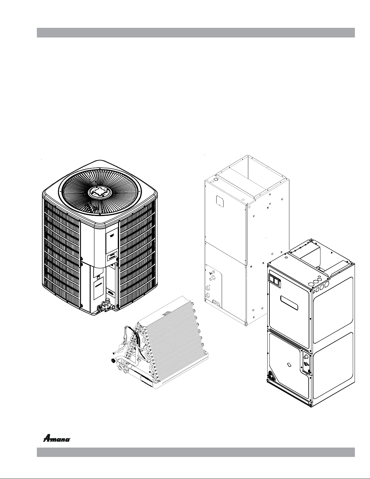
Service Instructions
ComfortNet™
ASXC, DSXC, and GSXC Condensing Units,
ASZC, DSZC and GSZC
with R-410A Refrigerant
Blowers, Coils, & Accessories
Split System Heat Pumps
This manual is to be used by qualified, professionally trained HVAC technicians only. Goodman
does not assume any responsibility for property damage or personal injury due to improper
service procedures or services performed by an unqualified person.
Copyright © 2015-2017 Goodman Manufacturing Company, L.P.
is a registered trademark of Maytag Corporation or its related companies and is used under license to Goodman Company, L.P., Houston, TX. All rights reserved.
RS6200007r14
December 2017
Page 2
IMPORTANT INFORMATION
Pride and workmanship go into every product to provide our customers with quality products. It is possible, however, that
during its lifetime a product may require service. Products should be serviced only by a qualified service technician who is
familiar with the safety procedures required in the repair and who is equipped with the proper tools, parts, testing instruments
and the appropriate service manual. REVIEW ALL SERVICE INFORMATION IN THE APPROPRIATE SERVICE MANUAL BEFORE
BEGINNING REPAIRS.
IMPORTANT NOTICES FOR CONSUMERS AND SERVICERS
RECOGNIZE SAFETY SYMBOLS, WORDS AND LABELS
WARNING
O
NLY PERSONNEL THAT HAVE BEEN TRAINED TO INSTALL, ADJUST, SERVICE OR
REPAIR (HEREINAFTER
MANUAL SHOULD SERVICE THE EQUIPMENT
BE RESPONSIBLE FOR ANY INJURY OR PROPERTY DAMAGE ARISING FROM
IMPROPER SERVICE OR SERVICE PROCEDURES
ASSUME RESPONSIBILITY FOR ANY INJURY OR PROPERTY DAMAGE WHICH MAY
RESULT
. IN
LICENSES TO SERVICE THE EQUIPMENT SPECIFIED IN THIS MANUAL, ONLY
LICENSED PERSONNEL SHOULD SERVICE THE EQUIPMENT
INSTALLATION, ADJUSTMENT, SERVICING OR REPAIR OF THE EQUIPMENT
SPECIFIED IN THIS MANUAL, OR ATTEMPTING TO INSTALL, ADJUST, SERVICE OR
REPAIR THE EQUIPMENT SPECIFIED IN THIS MANUAL WITHOUT PROPER
TRAINING MAY RESULT IN PRODUCT DAMAGE, PROPERTY DAMAGE, PERSONAL
INJURY OR DEATH
, “
SERVICE
”)
THE EQUIPMENT SPECIFIED IN THIS
. THE
MANUFACTURER WILL NOT
. IF
YOU SERVICE THIS UNIT, YOU
ADDITION, IN JURISDICTIONS THAT REQUIRE ONE OR MORE
. I
MPROPER
.
T
O PREVENT THE RISK OF PROPERTY DAMAGE, PERSONAL INJURY, OR DEATH,
DO NOT STORE COMBUSTIBLE MATER IALS OR USE GASOLINE OR OTHER
FLAMMABLE LIQUIDS OR VAPORS IN THE VICINITY OF THIS APPLIANC E.
To locate an authorized servicer, please consult your telephone book or the dealer from whom you purchased this product.
For further assistance, please contact:
CONSUMER INFORMA TION LINE
GOODMAN® BRAND PRODUCTS
TOLL FREE
1-877-254-4729 (U.S. only)
email us at: customerservice@goodmanmfg.com
fax us at: (713) 856-1821
(Not a technical assistance line for dealers.)
Outside the U.S., call 1-713-861-2500.
(Not a technical assistance line for dealers.) Your telephone company will bill you for the call.
is a registered trademark of Maytag Corporation or its related companies and is used under license to Goodman Company, L.P., Houston, TX. All rights reserved.
email us at: customerservice@goodmanmfg.com
AMANA® BRAND PRODUCTS
TOLL FREE
1-877-254-4729 (U.S. only)
fax us at: (713) 856-1821
(Not a technical assistance line for dealers.)
2
Page 3
IMPORTANT INFORMATION
SAFE REFRIGERANT HANDLING
While these items will not cover every conceivable situation, they should serve as a useful guide.
WARNING
REFRIGERANTS ARE H EAVIER T HAN AIR. THEY CAN "PUS H OUT" THE
OXYGEN IN YOUR LUNGS OR IN ANY ENCLOSED SPACE.
POSSI BLE DIFFI CULTY IN BRE ATHIN G OR DEATH:
EVER PURGE REFRIGERANT INTO AN ENCLOSED ROOM OR SPACE. BY
•
N
LAW, ALL REFRIGERANTS MUST BE RECLAIMED.
IF AN INDOOR LEAK IS SUSPECTED, THOROUGHLY VENTIL ATE THE AREA
•
BEFORE BEGINNING WORK.
IQUID REFRIGERANT CAN BE VERY COLD. TO AVOID POSSIBLE FROST-
•
L
BITE OR BL INDNESS, AVOID CONTACT W ITH REFR IGERANT AND WEAR
I
GLOVES AND GOGGLES.
SKIN OR EYES, SEEK MEDICAL HELP IMMEDIATELY.
A
LWAYS FOLLOW
•
AS POIS ONOUS GA S WILL BE PRODUC ED.
F LIQUID REFRIGERANT DOES CONTACT YOUR
EPA
REGULATIONS. NEVER BURN REFRIGERANT,
O AVO ID
T
WARNING
HE UNITED STATES ENVIRONME NTAL PROTECTION AGENCY ( "
T
HAS ISSUED VARIOUS REGULATIONS REGARDING THE INTRODUCTION AN D
DISPOSA L OF REFRI GERANTS INTRODUC ED INTO T HIS UNIT .
FOLLOW T HESE REGU LATIONS MAY HARM TH E ENVIRON MENT AND CAN
LEAD TO THE H IMPOSI TION O F SUBSTAN TIAL FIN ES.
MAY VARY BY JURISDICTION.
EPA OFFICE.
LOCAL
SHOULD QUEST IONS ARI SE, CO NTACT YOUR
THESE REGULATIONS
EPA
AILURE TO
F
WARNING
TO AVOID POSSIBLE EXPLOSION:
EVER APPL Y FLAME O R STEA M TO A REFR IGERAN T CYLINDE R. IF YOU
•
N
MUST HEA T A CYLIND ER FOR FAS TER CHARG ING, PARTI ALLY IMME RSE
IT IN WARM WATER.
NEVER FILL A CYLINDER MORE THAN 80% FULL OF LIQUID REFRIG ERANT.
•
NEVER ADD ANYTHING OTHER T HAN R-22 TO AN R-22 CYLINDER OR
•
R-410A TO AN R-410A CYLINDER. THE SERVICE EQUIPMENT USED MUST
BE LISTED OR CERTIFIED FOR THE TYPE OF REFRIGERANT USED.
TORE CYLIN DERS IN A COOL, DRY PL ACE. NEVER US E A CYLIND ER
•
S
AS A PLATFORM OR A ROLLER.
WARNING
TO AVOID POSSIBLE EXPLOSION, USE ONLY RETURNABLE (NOT DISPOSABLE)
SERVICE CYLINDERS WHEN REMOVING REFRIGERANT FROM A SYSTEM.
•
ENSURE THE CYLINDER IS FREE OF DAMA GE WHICH COULD LEAD TO A
LEAK OR EX PLOS ION.
•
")
ENSURE THE HYDROST ATIC TEST DATE DOES NO T EXCEED 5 YEARS.
•
ENSURE THE PRESSURE RATING MEETS OR EXCEEDS 400 LBS.
WHEN IN DOUBT, DO NOT USE CYLINDER.
WARNING
WARNING
SYSTEM CONTAMINANTS, IMPROPER SERVICE PROCEDURE AND/OR PHYSICAL
ABUSE AFFECTING HERMETIC COMPRESSOR ELE CTRICAL TERMINALS MAY
CAUSE DANGEROUS SYSTEM VENTING.
The successful development of hermetically sealed refrigeration compressors has completely sealed the compressor's
moving parts and electric motor inside a common housing,
minimizing refrigerant leaks and the hazards sometimes
associated with moving belts, pulleys or couplings.
Fundamental to the design of hermetic compressors is a
method whereby electrical current is transmitted to the
compressor motor through terminal conductors which pass
through the compressor housing wall. These terminals are
sealed in a dielectric material which insulates them from the
housing and maintains the pressure tight integrity of the
hermetic compressor. The terminals and their dielectric
embedment are strongly constructed, but are vulnerable to
careless compressor installation or maintenance procedures and equally vulnerable to internal electrical short
circuits caused by excessive system contaminants.
T
O AVOID POSSIBLE INJURY, EX PLOSION OR DEATH, PRACTICE SAFE
HANDLING OF RE FRIGERANTS.
In either of these instances, an electrical short between the
terminal and the compressor housing may result in the loss
of integrity between the terminal and its dielectric embedment. This loss may cause the terminals to be expelled,
thereby venting the vaporous and liquid contents of the
compressor housing and system.
A venting compressor terminal normally presents no danger
to anyone, providing the terminal protective cover is properly
in place.
If, however, the terminal protective cover is not properly in
place, a venting terminal may discharge a combination of
(a ) hot lubricating oil and refrigerant
(b ) flammable mixture (if system is contaminated
with air)
in a stream of spray which may be dangerous to anyone in the
vicinity. Death or serious bodily injury could occur.
Under no circumstances is a hermetic compressor to be
electrically energized and/or operated without having the
terminal protective cover properly in place.
See Service Section S-17 for proper servicing.
3
Page 4

PRODUCT IDENTIFICATION
s
ASXC 160241 AA
1 2 3 4,5 6 6 7 8,9
ComfortNet™
Brand
A - Ama na® bra nd Maj or/Mi nor Revi si on
D - Deluxe Goodman® brand
G - Goodman® brand
Type 1 - 208/230V Single-Phase 60 Hz
S 3 - 208/230V Three-Phase 60 Hz
Split Sys tem
4 - 460V Three-Phase 60 Hz
Type
C: Condenser R-22
H: Heat Pump R-22 024 - 2 Tons
X: Condenser R-410A 036 - 3 Tons
Z: Heat Pump R-410A 048 - 4 Tons
060 - 5 Tons
Communication Feature
C: 4-Wi re Communicati on Ready
SEER
16 - 16 SEER
18 - 18 SEER
Engineering
Voltage
Nominal Capacity
4
Page 5

PRODUCT IDENTIFICATION
A
=
ComfortNet™
CAP F 1824 A 6 A
1 2 3 4 5,6,7,8 9 10 11,12
Brand Engineering*
C Indoor Coi l
Unit Application 2 = R-22
A Upflow/Downflow Coi l
H Horizontal A-Coil
Horizontal Slab Coil
S
Coated Coils
T
Nominal Width for Gas Furnace
A = Fits 14" Furna ce Cabinet
B = Fits 17-1/2" Furnace Cabi net
C =
Fits 21" Furnace Cabinet
D = Fits 24-1/2" Furnace Cabinet
N
Does Not Apply (Horizontal Slab Coils
Major/Minor Revisions
Refrigerant Charge
4 = R-410A
6 = R-410A or R-22
Cabinet Finish
U Unpainted
PPainted
N Unpai nted Ca se
Expansion Device
FFlowrator
T 4 - 5 Tons
Expansi on Valve 4 - 5 Tons
1824 =
3030 =
3131 =
3636 =
3642 =
3743 =
4860 = Factory-Installed Non-Adjustable
4961 =
Nominal Capacity @ 13 SEER
1-1/2 - 2 Tons
2-1/2 Tons
2-1/2 Tons
3 Tons
3 - 3-1/2 Tons
3 - 3-1/2 Tons
5
Page 6

PRODUCT IDENTIFICATION
H
MB V C 12 00 A A 1
1,2 3 4 4 5,6 7 8 9
ComfortNet™
Brand
MB - Modular Blower 1: 208-230V/60Hz/1 P
Type A: First Seri es
Speed
V:
Communication Feature A: No Circui t Br eaker
C: 4-Wire Communication Ready
Airflow
12:
1200 CFM
16:
1600 CFM
20:
2000 CFM
B: Ci rcuit Breaker
Elect rical
Design Se ries
Circuit Breaker
Factory Heat
00 No Heat
6
Page 7

PRODUCT IDENTIFICATION
A V P T C 1830 1 6 AA
1 2 3 4 5 6,7,8,9 11 12 13,14
ComfortNet™
Brand
A Airhandler
Unit Application
Vari a bl e Sp eed Motor
V
Cabinet Finish
U: Unpa inted
P: Painted 1 208/240V, 1 Phase, 60 Hz
N: Uncas ed
Expansion Device
F: Fl owrator
T: Expansion Valve
Communications
C: 4-Wire Communi cati on Ready
Multi-Position & Downflow Applications
Ceiling Mount & Wall Mount Applications
Maj or/Mi nor Revi si ons
1830 = 1-1/2 to 2-1/2 Tons
3137 = 3 Tons
4260 = 3-1/2 to 5 Tons
Engineering*
Refrigerant Charge
No Di git = R-22 Onl y
6 = R-410A or R-22
Electrical
Nominal Capacity
7
Page 8
PRODUCT IDENTIFICATION
A
V
PTC18B1 4AA
1 2 3 4 5 6,7 8 9 10 11,12
ComfortNet™
Brand
A Si ngl e Piec e
Ai rhandl er
Unit Application
C Ceiling Mount PSC Motor 4 = R-410a
R Multi Position PSC Motor
S Multi Posi tion EEM Motor
W Wall Mount PSC/EEM Motor 1 208/240V, 1 Phase, 60 Hz
VMulti Position
Variable Speed Motor -
Communi cating
Cabinet Finish
U Unpainted
PPainted
NUncased
Expansion Device
FFlowrator 31 = 2 Tons
TExpansion Valve 33 = 1 1/2 - 2 Tons
Communications
ComfortNet
C
TM
Compatible
*Not used for inventory management
Nominal Capacity
Major/Minor Revisions
18 = 1-1/2 Tons
24 = 2 Tons
25 = 2 Tons
29 = 2 Tons
30 = 2-1/2 Tons
36 = 3 Tons
37 = 2 1/2 - 3 1/2 Tons
39 = 2 1/2 - 3 Tons
42 = 3-1/2 Tons
48 = 4 Tons
49 = 3 - 3 1/2 Tons
59 = 4 - 5 Tons
60 = 5 Tons
61 = 4 - 5 Tons
Engineering*
Refrige rant Charge
Electrical
Cabinet Width
B = 17-1/2"
C = 21"
D = 24-1/2"
All Airhandlers use DIRECT DRIVE MOTORS. Power supply is AC 208-230v, 60 hz, 1 phase.
8
Page 9
PRODUCT IDENTIFICATION
ASXC16
MANA® BRAND SPLIT
A
Model/Rev Description
ASXC160 **1AA
AS XC160601BA Use ZPS49 compress or.
AS XC160481BA Smart Coi l® coil s
AS XC160(24/36)1BB Wi ring diagram updat ed wit h notes .
AS XC160(48-60)1BB Motor changed t o Nidec.
Introduces Amana® brand 2-stage 16 SEER condensing units with R-410A,
communicati ng m o dels.
OMMUNICATING CONDENSERS R-410A 16 SEER
X-C
ASXC160 (2 4/36)1BC
ASXC160 (4 8- 60) 1BC
ASXC160 (2 4/36)1BD
ASXC160 (4 8- 60) 1BD
AS XC160(241, 481)B E Refrigerant charge reduction
AS XC160(24,36,48,60)1CA 16 SE ER 2-Stage AC Developm ent with improved performance.
Ultrat ec h® 2.0 c ompressor change.
Replaced P CB HR103 Communicating Heat P um p Control B oard wit h PCBHR104
Communicating Heat P um p Control Board.
ASXC18
MANA® BRAND SPLIT
A
Model/Rev Description
ASXC18**1AA
AS XC180(36/48/ 60)1AB Wi ring di agram updated wit h not es .
ASXC180 (3 6/48-60)1AC
Initial release of Amana® brand 2-st age 18 SEER condensing units with R-410A ,
communicati ng m o dels.
Replaced compressors ZP S 20K4EPFV230 with ZPS20K5E P F V130 and compressor
ZPS30K4EPFV230 with ZPS30K5EPFV130.
OMMUNICATING CONDENSERS R-410A 18 SEER
X-C
ASXC180 (3 6/48/60)1AD
ASXC180 48 1BB
Replaced P CB HR103 Communicating Heat P um p Control B oard wit h PCBHR104
Communicating Heat P um p Control Board.
[Design Improvement]: Updating shared data for 18 SEER, 2-stage, 4 ton AC in
com m unicating installat i ons. Releasi ng m inor revision for affec ted models
9
Page 10
PRODUCT IDENTIFICATION
GSXC16
OODMAN® BRAND SPLIT
G
Model / Re v Description
GSXC160( 24/36/48/60)1CA
OODMAN® BRAND SPLIT
G
Model / Rev Description
GSXC180( 24/36/48/60)1BA
GSXC180481BB
OMM UNICA T IN G CONDENSERS R-410A 16 SEER
X-C
16 SEER 2-Stage AC Development wi t h i m proved performan c e.
GSXC18
OMM UNICA T ING CONDEN SERS R-410A 18 SEER
X-C
18 SEER 2-Stage AC Development with improved performance.
[Design Improvement]: Updating shared data for 18 SEER, 2-stage, 4 ton AC in
communic a t i ng i nstall ations . Releasi n g m i no r revision for affect ed m odel s
10
Page 11
PRODUCT IDENTIFICATION
DSXC16
ELUXE SPLIT
D
Model/Rev Description
DSXC160**1AA
DSXC160(24/36)1AB Wiring diagram updat ed with notes.
DSXC160(24/36)1AC
DSXC160(48-60)1BC
DSXC160481BA Sm artCoil ® coils.
DSXC160601BA ZPS49K compress or.
DSXC160(48-60)1BB Motor c hanged t o Nidec.
DSXC160241AF
DSXC160481BE
Initial release of Goodman® Deluxe brand 2-st age 16 S E ER condensing units with R410A, communicating models.
Ult ratech® 2.0 compressor.
Refri gerant charge reduction
OMMUNICATING CONDENSERS R-410A 16 SEER
X-C
DSXC18
DELUXE SPLIT X-C
Model/Rev Description
DSXC18**1AA
DSXC180(36/48/60] 1AB W i ring di agram updat ed wit h not es.
DSXC18036AC
DSXC180(48-60)1AC Ult ratech® 2.0 compress or c hange.
Initial release of Goodm an® Deluxe brand 2-s tage 18 SEE R c ondens ing uni t s with R410A, communic ating models .
Replaced c om pres sors ZPS20K4E P F V230 with ZPS20K5E P F V 130 and c om pres s or
ZPS30K4EPFV230 with ZPS30K5EPFV130.
OMMUN ICATING CONDENSERS R-410A 18 SEER
11
Page 12
PRODUCT IDENTIFICATION
Model/Rev Description
ASZC160**1AA
MANA® BRAND SPLIT
A
Introduces A m ana ® brand 2-stage 16 SE ER heat pum p u ni ts with R-410A,
com municating m odel s.
OMMUNICATING HEAT PUMP R-410A 16 SEER
Z-C
ASZC16
ASZC160(24/36)1AB
ASZC160(48/60)1AB
ASZC160(24-48)1AC
ASZC160601BA
ASZC160(24-36])1AD
ASZC160601BB
ASZC160(24-36)1AE
AS ZC160481A E Ult rat e ch® 2. 0 compres sor change.
ASZC160[24/36/48/60]1C A
Sanhua ( RA NCO) reversing valves
Releas e of mod el s with accum ul ators and crankcase heaters.
Mot or changed t o Ni dec.
Replaced compres sors ZPS20K4EP F V 230 wit h ZPS20K 5E P F V 130 and com pres s or
ZPS30K4EPFV230 with ZPS30K5EPFV130.
Replac ed compres sors with Copeland's UltraTech™ 3 l i neup . Trans i tioned coils to 7mm.
Offers improved performance.
ASZC18
Model/Rev Description
ASZC180**1AA
MANA® BRAND SPLIT
A
Introduces A m ana ® brand 2-stage 18 SE ER heat pum p u ni ts with R-410A,
com municating m odel s.
OMMUNI CATING HEAT PUMPS R-410 A 18 SEER
Z-C
ASZC180601BC
ASZC180601BB
ASZC180(36/48/60)1A B Relea se of models with accum ul ators and crankcase heaters.
ASZC180(36-4)]1AC
ASZC180601BA
ASZC180361AD
ASZC180[24/36/48/60]1C A
Ult rat e ch® 2. 0 compres sor change.
Sanhua ( RA NCO) reversing valves
Replac ed compres sors with Copeland's UltraTech™ 3 l i neup . Trans i tioned c oils to 7mm.
Offers improved performance.
12
Page 13
PRODUCT IDENTIFICATION
GSZC16
OODMAN® BRAND SPLIT
G
Model/Re v Description
GSZC160[24/36/48/60]
OODMAN® BRAND SPLIT
G
Model/Rev Descripti on
GSZC180[24/36/48/60]
OMMUN ICATING HEAT PUMP R-410A 16 SEER
Z-C
Replaced c om pres s ors with Copeland's UltraTech™ 3 l ineup. Transit i oned c oi ls
to 7mm . O ffers improved performance.
GSZC18
OMMUNICATING HEAT PUMP R-410A 16 SEER
Z-C
Replac ed c om pressors wi t h Copel and's Ul t raTech™ 3 li neup. Transiti oned coils
to 7m m. Offers i m proved performance.
13
Page 14
PRODUCT IDENTIFICATION
DSZC16
ELUXE SPLIT
D
Model/Rev Description
DSZC16**1AA
DSZC160( 24 /36)1AB
DSZC160( 48 /60)1AB
DSZC160( 24 - 48) 1 AC
DSZC160601 BA
DSZC160( 24 - 48) ]1AD
DSZC160601 BB
DSZC160481 AE
DSZC160601 BC
DSZC160( 24 - 36) 1 AE
Initial release of Goodman® brand Deluxe 2-st age 16 S E ER heat pump units with R410A, communicating models.
Sanh ua (RANCO) revers i ng valves .
Release of models wi t h ac cumulators and crankcase heaters.
Ultrat ec h® 2.0 com pres sor change.
Replaced c om pres sors ZPS20K4E P F V230 with ZPS20K5E P F V 130 and c om pres s or
ZPS30K4EPFV230 with ZPS30K5EPFV130.
OMMUN ICATING HEA T PUMP R-410A 16 SEER
Z-C
DSZC18
DELUXE SPLIT Z-C
Model/Rev Description
DSZC18**1AA
Initial release of Goodm an® brand Delux e 2-s t age 18 S E E R heat pum p unit s with R410A, communic ating models .
OMMUN ICATING HEAT PUMP R-410A 18 SEER
DSZC180(36/ 48/ 60)1A B Sanhua (RANCO) reversing valves.
DSZC180361 AD
DSZC180( 36 - 48) 1 AC
DSZC180601 BA
DSZC160( 24 - 48) 1 AD
DSZC160601 BB
Replaced c om pres sors ZPS20K4E P F V230 with ZPS20K5E P F V 130 and c om pres s or
ZPS30K4EPFV230 with ZPS30K5EPFV130.
Release of models wi t h ac cumulators and crankcase heaters.
Ultrat ec h® 2.0 com pres sor change.
AVPTC****14
SINGLE PIECE AIR HANDLER MULTIPLE-POSITION VA RIA BLE SPEED
AINTED TXV WITH 4 -WIRE COMMUNICATING CON TROL
P
Model/Rev Description
AVPTC183014AA
AVPTC313714AA
AVPTC426014AA
AVPTC183014AB
AVPTC313714AB
AVPTC426014AB
Initial release of 13 SEER air handler with communicating control and serial
com m unicating indoor blower mot or.
Replaced P CBJA 10 c om m unicating air handler c ont rol board wit h P CB JA103.
14
Page 15

PRODUCT IDENTIFICATION
AVPTC**14
SINGLE PIECE AIR HANDLER MULTIPLE-POSITION VARIABLE SPEED
AINTED TXV WITH 4-WIRE COMMUNICATING CONTROL
P
Model/Re v Description
AVPTC24B14AA
AVPTC(30/36)C14AA
AVPTC(42/48/60)D14AA
AVPTC48C14AA Updated S&R and travel labels.
Initial release of 13 SEER air handler with communicating control and serial
comm uni cating indoor blower motor. Redes ign of AV PTC models to new ai r handler
cabinetry. Incorporated 4-way, mult-position body utilized on ARTP/ASPt mdoels.
AVPTC(42/48/60)14AB
AVPTC60D14AC Serial plate update
AVPTC24B14AC
AVPTC30C14AB
AVPTC25B14AA
AVPTC29B14AA
AVPTC31C14AA
AVPTC37B14AA
AVPTC37C14AA
AVPTC37D14AA
AVPTC49D14AA
AVPTC59C14AA
AVPTC59D14AA
AVPTC61D14AA
AVPTC33C14AA
AVPTC39C14AA
AVPTC49C14AA
AVPTC35B14AA Introducing 2.5 and 3 Ton Air Handler product lines.
Redesign of AVPTC models to new air handler cabinetry. Incorporated 4-way, mul t position body utilized on ARTP/ASPt mdoels.
Heater Kit ai rflow update.
AV PTC Effi cienc y Upgrades
The new A V P TC redesign will i ncorporat e t he upgrade blower, c oil pan and coi l design
int e nded to inc rease effici en cy and standard i ze production.
Upgrade the current AVPTC C-49 cabinets to include 1. quality improvements captured in
Ready15 design. 2.include redesi gned drain pan, Morrison blower hous i ng and Em ers on
NXT Booster Charge Adjustable TXV.
AVPTC[31,37,39,49,59]C14AB
AVPTC[37,59,61]D14AB
AVPTC[25,29, 37]B14AB
AVPTC33C14AB
AVPTC[31, 37,39,49,59]C14AC
AVPTC49D14AB
AVPTC[37,59,61]D14AB
AVPTC35B14AA
Revis ions because of New Heater kit s released
Air handler revisions due to us i ng an upgraded (thic ker with higher R value)
Quietflex wrapper insulation.
The SR plate format i s chang i ng from SR075 to SR099 and in ord er to track t hi s chan ge
a minor revision is nec essary.
15
Page 16
PRODUCT IDENTIFICATION
MBVC
ODULAR BLOWER AIR HAN DLER V-MULT I-POSITION VARIABL E-SPEED
M
OMMUNICAT ING REA D Y W/4-WIRES
C
Model/Rev Description
MBVC1200AA1-AA
MBVC1600AA1-AA
MBVC2000AA1-AA
MBVC1200AA1-AB
MBVC1600AA1-AB
MBVC2000AA1-AB
MBVC1200AA1-AC
MBVC1600AA1-AC
MBVC2000AA1-AC
MBVC1200AA1-AD
MBVC1600AA1-AD
MBVC2000AA1-AD
MBVC[1200,1600,2000]A A 1-A E Release of MBR/MBVC Models (M inor Revisions) for 11th St Plant. - Dayton to Houston
Introducti on of module blower with variabl e s peed blower motor wit h t he new
comm uni c at i ng c ont rol & s erial c om m unicating indoor blower motor.
Introducti on of a module blower with variable speed blower mot or wit h communic at ing
cont rol & s eri al c om m unicating indoor blower motor. Replac es exist ing E m ers on motors
(013M00111 & 013M00112).
Introducti on of a module blower with variable speed blower mot or wit h communic at ing
cont rol & s eri al c om m unicating indoor blower motor. Quali t y improvement t o us e 0.75"
Quiet Flex Insulation.
Introducti on of a module blower with variable speed blower mot or wit h communic at ing
cont rol & s eri al c om m unicating indoor blower motor. Introduc es a new Communic ating Air
Handler Control Board (PC).
MBVC[1200,1600,2000]AA1-AF
Add permanent s eali ng/ condensation-c ont rol upgrades t o all MB units and remove highvolt age knockout s
CAUF
INDOOR COIL A-UPFLOW/DOWNFLOW UNCASED FLOWRATOR
C-
Model/Rev Description
CAUF*****6AA Initial release of CAUF Dayton Upflow/ Downfl ow coil s .
CAUF*****6BA Burr Oak Louvered Fin released in place of the Wavy Fin.
CAUF****6*DA Replace d
CAUF*****6DB Drain pan material c hanged.
CAUF1824A6RDB
CAUF1824B6RDB
CAUF36***CA Redesign from 2 row to 3 row for performanc e im provement .
CAUF3030(A/B)6RDB
CAUF3030(C/D)6RDB
CAUF3131(B/C)6RDB
Manufact uring Loc at i on Change from Dayton t o Hous t on. Designated by "R".
Manufact uring Loc at i on Change from Dayton t o Hous t on. Designated by "R".
exi s ting copper coi ls and other ass ociated parts with aluminum components .
16
Page 17

PRODUCT IDENTIFICATION
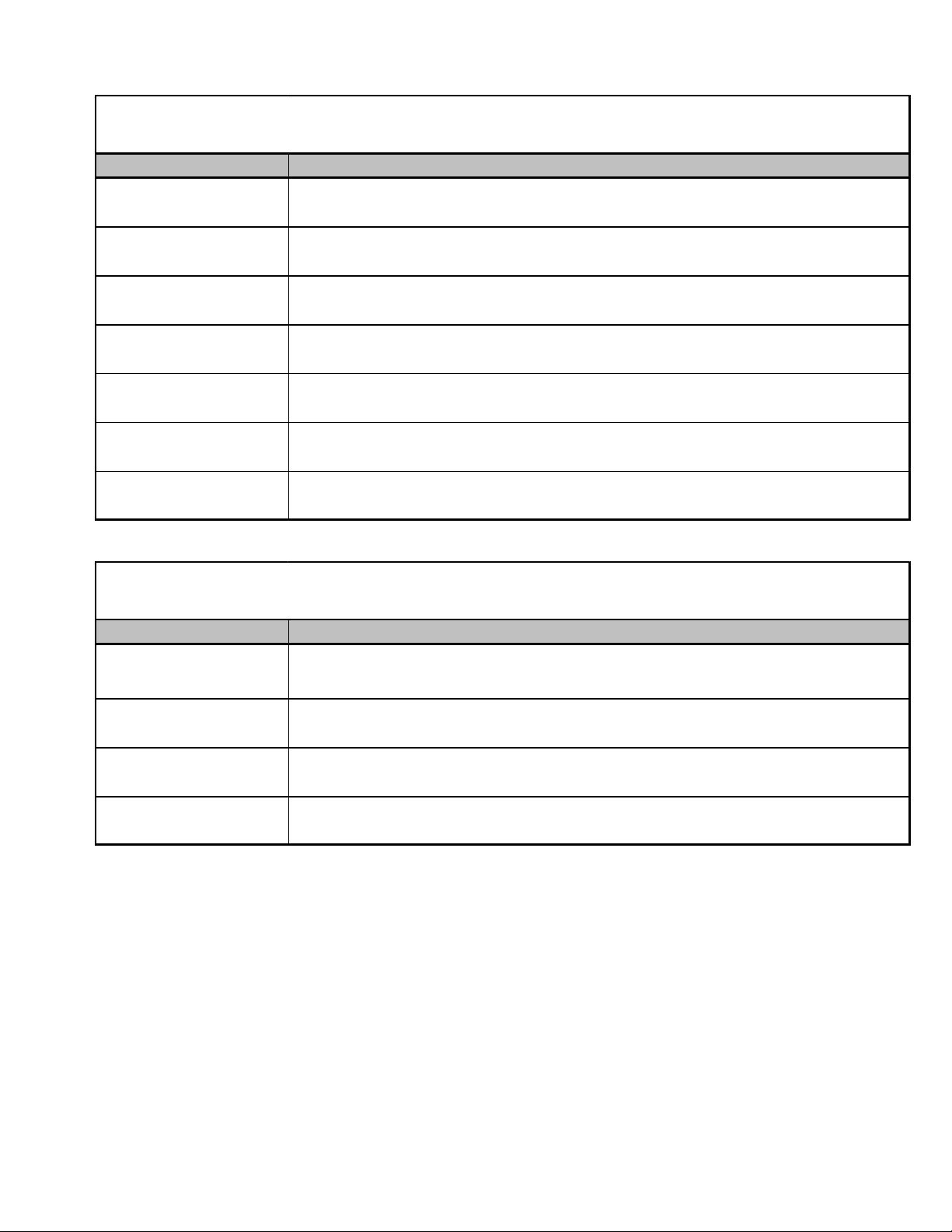
CHPF
-INDOOR COIL HORIZONTAL A-COIL PAINTED FLOWRATOR
C
Model/Rev Description
CHPF*****6AA Intial release of 13 S E E R CHPF horizont al A c oi l.
CHPF*****6BA
CHPF1824A6CA
CHPF2430B6CA
CHPF3636B6CA
CHPF3642C6CA
CHPF3642D6CA
CHPF3743C6BA
CHPF3743D6BA
CHPF4860D6DA
CHPF1824A6CB
CHPF2430B6CB
CHPF3636B6CB
CHPF3642C6CB
CHPF3642D6CB
CHPF3743C6BB
CHPF3743D6BB
CHPF4860D6DB
CHPF1824A6CC
CHPF2430B6CC
CHPF3636B6CC
CHPF3642C6CC
CHPF3642D6CC
CHPF3743C6BC
CHPF3743D6BC
CHPF4860D6DC
Released B urr Oak Louvered Fin in place of the Wavy F i n. The rows changed by one, (i. e.
4 row to 3 row; 3 row to 2 row) where appli cable.
Louvered fins. Replaced copper tube hairpins wi t h al umi num hairpins.
Drain pan material change to a Decabromodipheny l E t her free resin.
Change to prepainted wrappers
17
Page 18
PRODUCT IDENTIFICATION
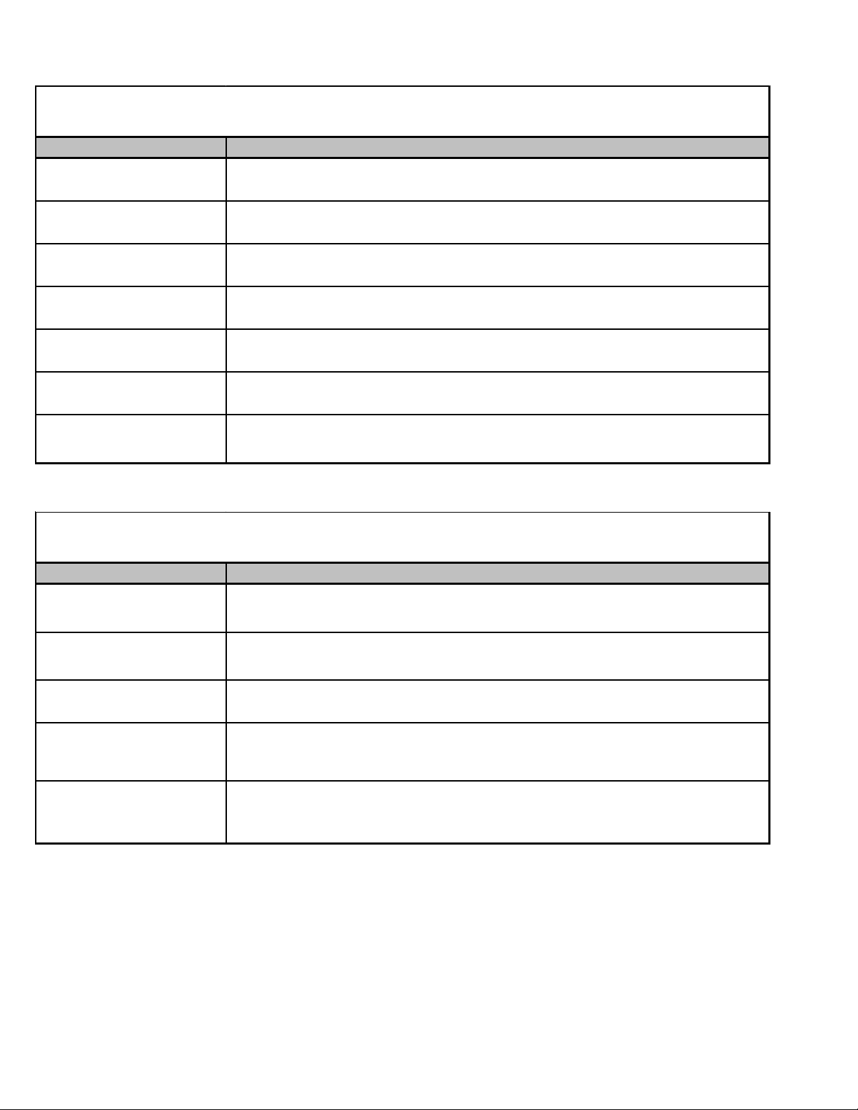
CAPF
INDOOR COIL A-UPFLOW/DOWNFLOW PAINTED FLOWRATOR
C-
Model/Rev Description
CAPF*****6A A Initial release of CAPF Dayt on Upflow/Downflow coils .
CAPF*****6B A Burr Oak Louvered Fin released in place of the Wavy F in.
CAPF36***CA Redesigned for performance improvement from 2 row t o 3 row.
CAPF* ****6DA Replaced exi sting c opper c oil s and other ass ociated parts with aluminum components .
CAPF*****6DB Drain pan mat erial c hanged.
CAPF182 4A6DC
CAPF182 4B6DC
CAPF182 4C 6D C
CAPF303 0A6DC
CAPF303 0B6DC
CAPF303 0C 6D C
CAPF303 0D 6D C
CAPF313 1B6DC
CAPF313 1C 6D C
CAPF313 7B6AB
CAPF363 6A6DC
CAPF363 6B6DC
CAPF363 6C 6D C
CAPF363 6D 6D C
CAPF364 2C 6D C
CAPF364 2D 6D C
CAPF374 3C 6D C
CAPF374 3D 6D C
CAPF486 0C 6D C
CAPF486 0D 6D C
CAPF496 1C 6D C
CAPF496 1D 6D C
Redesign t he wrapper for the CAPF t o provide increased eas e of ins tallati on.
C-
Model/Rev Description
CAPT3131B4BA
CAPT3131C4BA
CAPT3743C4AA
CAPT3743D4AA
CAPT4961C4AA
CAPT4961D4AA
CAPT3131B4AB
CAPT3131C4AB
CAPT3743C4AB
CAPT3743D4AB
CAPT4961C4AB
CAPT4961D4AB
18
INDOOR
CAPT
COIL
UPFLOW /DOWNFLOW PAINTED CASED FLOWRATOR W/TXV
A-
Initial release of coils with factory-installed, non-adjus table TXV . Single s t age A HRI ratings
for CAPT3131 NTC combinat i ons .
Initial release of single s t age A HRI ratings for CAPT3743 NTC c ombi nat i ons .
Initial release of single s t age A HRI ratings for CAPT4961C4 NTC com binations.
Redesign t he wrapper for the CAPT to provide inc reased ease of inst all at i on.
Page 19
PRODUCT IDENTIFICATION
CSCF
INDOOR COIL S-HORIZONTAL SLAB COIL C-UNPAINTED FLOWRATOR
C-
Model/Rev Description
CSCF*****6AA Initial release of 13 SEER CSCF horizontal slab coils.
CSCF*****6BA
CSCF1824N6BB
CSCF3036N6BB
CSCF3642N6CB
CSCF4860N6CB
CSCF1824N6CA
CSCF3036N6CA
CSCF3642N6CA
CSCF4860N6CA
Burr Oak Louvered F in releas ed i n place of the Wavy Fin. Rows reduc ed by one where
applicable.
Drain pan material changed.
Replaced c opper c oil s and other ass oc i at ed part s with alumi num components .
19
Page 20
ACCESSORIES
ComfortNet™
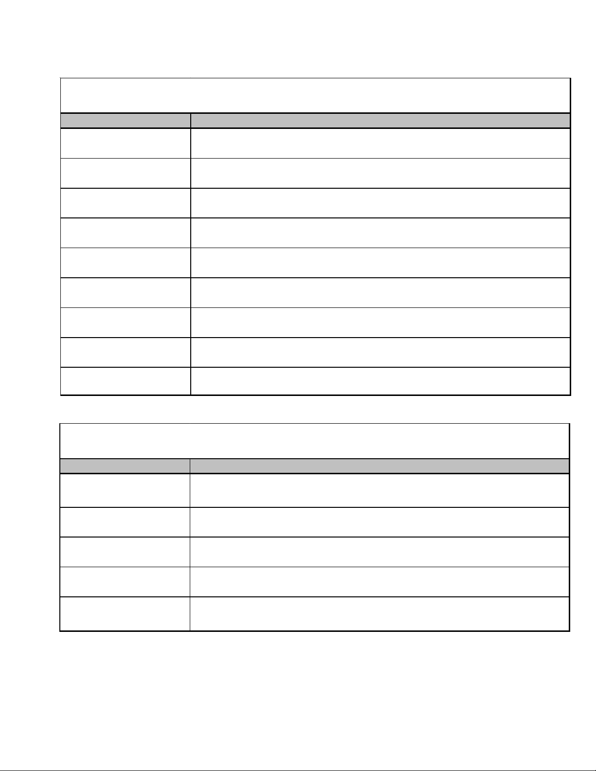
ASXC/DSXC 16
ASXC/DSXC/GSXC 18
Model Description
ABK-20 Anchor B racket Kit X X X X X X X X
ASXC16024
DSXC16024
ASXC16036
DSXC16036
ASXC16048
DSXC16048
ASXC16060
DSXC16060
ASXC18024
DSXC18024
GSXC18024
ASXC18036
DSXC18036
GSXC18036
ASXC18048
DSXC18048
GSXC18048
ASXC18060
DSXC18060
GSXC18060
TX2N4A TXV Kit
TX3N4 TXV Kit
TX5N4 TXV Kit
CSR-U-1 Hard-start Kit
CSR-U-2 Hard-start Kit
CSR-U-3 Hard-start Kit
1
FSK01A
LSK02*
B1141643
* Contains 20 brackets; four brackets needed to anchor unit to pad.
Installed on the indoor coil.
Available in 24V legacy mode only. This feature is integrated in the communicating mode.
This component is included in the CTK0*** communicating thermostat kit.
Freeze Prot ection Kit
Liquid Line Solenoid
Valve
3
24V Transformer
XX
XX
XX X X
XX
XX
XX X X
XXXXX X X X
XXXXX X X X
XXXXX X X X
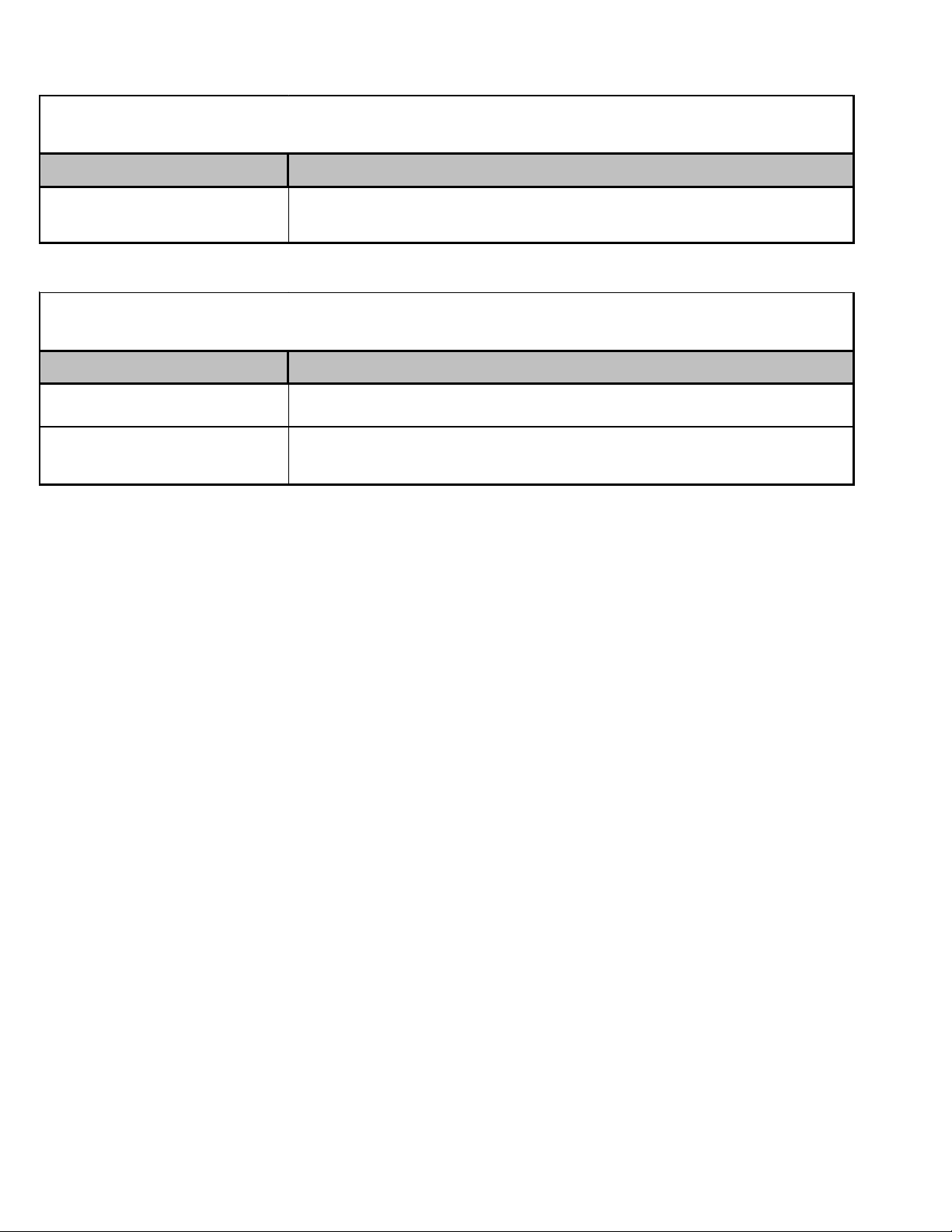
ASZC/DSZ C 16
ASZC/DSZ C 18
Model Description
ASZC16024
DSZC16024
ABK-20Anchor Bracket KitXXXXXXX
1
TX2N4
TX3N4
TX5N4
TXV Kit X
1
TXV Kit X X
1
TXV Kit X X X X
CSR- U-1 Hard -star t Kit X X X
CSR- U-2 Hard -star t Kit X X X X X X
CSR- U-3 Hard -star t Kit X X X X
2
FSK01A
LSK02*
OT18-60A
B1141643
Freeze Protection KitXXXXXXX
Liquid Line Solenoid
Valve
Outdoor Thermostat/
3
Lockout Thermostat
4
24V TransformerXXXXXXX
XXXXXXX
XXXXXXX
ASZC16036
DSZC16036
ASZC16048
DSZC16048
ASZC16060
DSZC16060
ASZC18036
DSZC18036
ASZC18048
DSZC18048
ASZC18060
DSZC18060
20
* Conta ins 20 bracke t s; four brack et s needed to ancho r unit to pad
1
Field -installed, non-bleed, ex p ans i on valve k i t - Condensing unit s and heap pumps wi t h reciprocat i ng c o mp res sors require t he
use of s t art -assist com ponent s when used in conjunct i on with an indoor coil using a non-bleed the rmal expansion valve
refrigerant
2
Insta ll ed on t he i ndoor c oi l
3
Available in 24V l egacy mode onl y. This feature is integrat ed i n t he c om m uni c ating mode. Requi red for heat pum p appl ications
where ambient t em pe rat ure fall bel ow 0 °F with 50% or higher relat i ve humidit y.
4
This c om ponent i s incl uded in the CTK 0*** c omm unic at ing t hermost at kit.
Page 21
ACCESSORIES
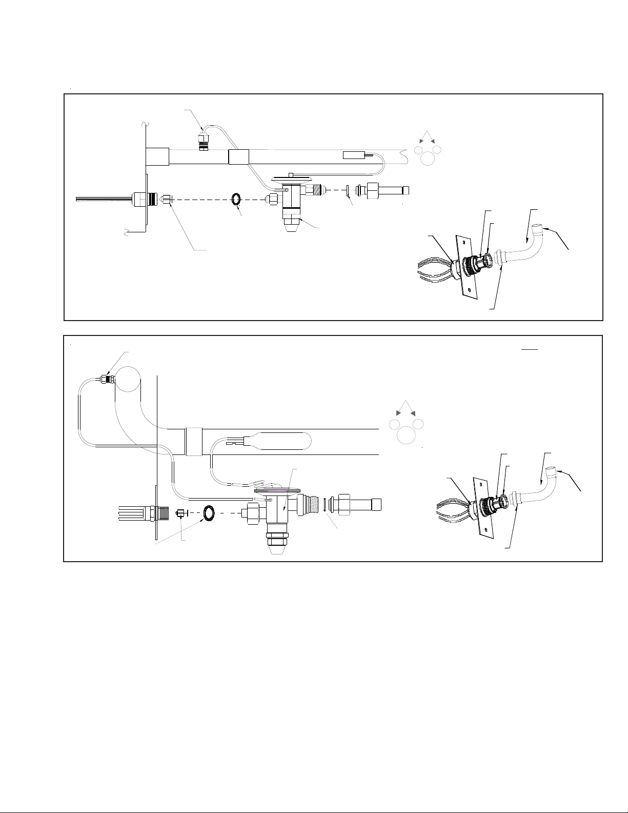
EXP ANSION VALVE KITS
1/4 FLARE CONNECTION
BULB TO BE LOCATED
AT 10 OR 2 O'CLOCK
For Applications requiring
a field installed access fitting
EVAPORATOR COIL
EVAPORATOR COIL
1/4' F L A RE
CONNECTION
SEAL SUPP L IE D W/ KIT
REMOVE BEFORE INSTALLI NG EXP ANS IO N VALVE
SUCTION LINE
BULB
EXPANSION VALVE
SUCTION LINE
EXPANSION VALVE
BULB
SEAL SUPPLIED W/ KIT
BULB TO BE LOCATED
AT 10 OR 2 O'CLOCK
DISTRIBUTOR
BODY
For Applications not requiring
a field installed access fitting
DISTRIBUTOR
BODY
7/8" NUT
PISTON
SEAL
PISTON
SEAL
TAILPIECE
3/8"SWEAT
TAILPIECE
3/8"SWEAT
SEAL SUPPLIED W/ KIT
REMO VE BEFORE
INSTALLING
EXPANSION VALVE
SEAL SUPPLIED W/ KIT
7/8" NUT
21
Page 22
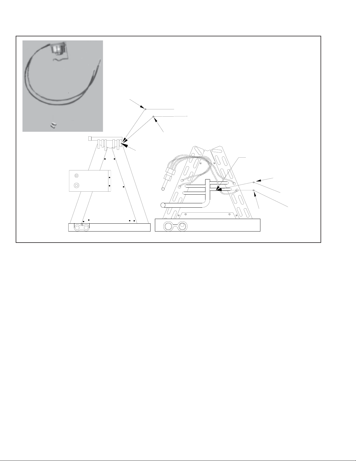
ACCESSORIES
Wire Nut
FSK01A
FREEZE THERMOSTAT
KIT
Y
k
c
a
l
B
k
c
a
l
B
Wire Nut
Y
Install Line
Thermostat
Here
Install Line
Thermostat
Here
B
l
a
c
B
l
Wire Nut
Wire Nut
Y
k
a
c
k
Y
22
Page 23
ACCESSORIES
BLOWER
ELECTRIC HEAT KIT
NO HEAT
MBVC1200 AA-1* *
MBVC1600 AA-1* *
MBVC2000 AA-1* *
X = A llowable combinations
- = Restricted combinations
-XXXXXX- - -
-XXXXXX- - -
-XXXXX- X- -
ELECTRIC HEAT KIT APPLICATIONS - MBVC
HKR-03*
^ = Circuit 1: Single P hase for A ir Handler Motor
Circuit 2: 3-Phase for HKR3 Heater Kits
HKR05-(C)'
HKR-06*
HKR-08(C)*
HKR-10(C)*
HKA-15C*
HK* SERIES ELETRIC HEA T KITS -
HKA-20C*
^HKR3-15*
^HKR3-20A
23
Page 24

ACCESSORIES
ELECTRIC HEAT KIT APPLICATIONS - A VPTC
MODELS HKR-03* HKR-05*/-05C* HKR-06* HKR-08*/-08C* HKR-10*/-10C* HKR-15C* HKR-20C* HKR-21C* HKA-15C* HKA-20C*
AVPTC183014A* X X X
AVPTC313714A* X X X
AVPTC426014A* X X X X X X X3 X3 X
* Revision level that may or may not be designated.
C Circuit breaker option.
NOTE:
When 8kW and 10kW heat kits are used with an AVPTC1830 and AVPTC3137, matched with 2- ton outdoor unit, see Note 1 below.
1
Set Heater Kit dip switches 9, 10 and 11 to 6kW setting (9-ON, 10-OFF,11-ON) to obtain 840 CFM.
2
This heater kit can only be used for ‘1000 CFM or higher’ applications.
3
This heater kit can only be used for ‘1200 CFM or higher’ applications.
1
X
1
X
1
X
1
X
--- --- --- --- ---
X 2 --- ---
2
X
X
3
X
24
Page 25
ACCESSORIES
p
p
p
p
p
AVPTC**14**
Heat Kit Applications
Type / Model 24B14-A* 30C14-A* 36C14-A* 48C14-A* 42D14-A*
HKSX03XC X X X
HKSX05XC XXXXXXX
HKSX06XC XXXXXXX
HKSX08XC XXXXXXX
HKSX10XC XXXXXXX
HKSX15XF* XXXXX
HKSX20XF* XXXXX
HKSC05XC XXXXXXX
HKSC08XC XXXXXXX
HKSC10XC XXXXXXX
HKSC15XA XXXXX
HKSC15XB XXXXX
HKSC15XF* XXXXX
HKSC19CA* X X
HKSC19CB* X X
HKSC20DA XXX
HKSC20DB XXX
HKSCX20XF* XXXXX
HKSC25DC* XX
* Revision level that may or may not be designated.
Refer to the minimum airflow requirements for each of the heat kits.
AVPTC
†
48D14-A*
††
60D14-A*
†††
†For m atch u p wi th a 2 ton outdoo r uni t: Hea ter ki t ap pli caƟon shall not exceed 10 kW.
Airflow for 5 kW u
††For ma tch u
Airflo w for 5 kW u
†††For ma tch u
Airflo w for 5 kW u
** 3 kW heater kit is not applicable for this indoor application.
to 10 kW hea ter ki ts s hall be s et to 850 cfm speed tap of ON-ON-ON.
wi th a 3 ton ou tdoo r uni t: Hea ter ki t applicaƟon shall not exceed 15 kW.
to 15 kW hea ter ki ts s hall be s et to 1400 cfm speed tap of ON-ON-OFF.
wi th a 3.5 ton ou tdoo r uni t: Hea ter ki t applicaƟon shall not exceed 20 kW.
to 20 kW hea ter ki ts s hall be s et to 1620 cfm speed tap of ON-ON-OFF
25
Page 26
ACCESSORIES
READY 15 AVPTC
Model AVPTC25B14 AVPTC29B14 AVPTC31C14 AVPTC33C14 AVPTC35B14 AVPTC39C14 AVPTC37B14 AVPTC37C14 AVPTC37D14 AVPTC49C14 AVPTC49D14 AVPTC59C14 AVPTC59D14 AVPTC61D14
HKSX03XC XX XX X
HKSX05XC XXXXXXXXXXXXXX
HKSX06XC XXXXXXXXXXXXXX
HKSX08XC XXXXXXXXXXXXXX
HKSX10XC XXXXXXXXXXXXXX
HKSC05XC XXXXXXXXXXXXXX
HKSC08XC XXXXXXXXXXXXXX
HKSC10XC XXXXXXXXXXXXXX
HKSC15XA XXXXXXXXXXX
HKSC15XB XXXXXXXXX XXXXX
HKSC15XF XXXXXXXX
HKSC19CA XXXX
HKSC19CB XXXXX
HKSC19CH X
HKSC20DA X
HKSC20DB XXX
HKSC20DH XX
HKSC20XF XXXX
HKSC25DA X
HKSC25DB X
26
Page 27
PRODUCT DESIGN
This section gives a basic description of cooling unit operation, its various components and their basic operation.
Ensure your system is properly sized for heat gain and loss
according to methods of the Air Conditioning Contractors
Association (ACCA) or equivalent.
CONDENSING UNIT
The condenser air is pulled through the condenser coil by a
direct drive propeller fan. This condenser air is then discharged out of the top of the cabinet. These units are
designed for free air discharge, so no additional resistance,
like duct work, shall be attached.
The suction and liquid line connections on present models
are of the sweat type for field piping with refrigerant type
copper. Front seating valves are factory installed to accept
the field run copper. The total refrigerant charge for a normal
installation is factory installed in the condensing unit.
ASXC, ASZC, DSXC, DSZC models are available in 2
through 5 ton sizes and use R-410A refrigerant. They are
designed for 208/230 volt single phase applications.
ASXC, ASZC, DSXC, DSZC R-410A model units use the
Copeland Scroll "Ultratech" Series compressors which are
specifically designed for R-410A refrigerant. These units also
have Copeland
ComfortAlert diagnostics are integrated into the unitary (UC)
control. These models are ComfortNetTM ready.
There are a number of design characteristics which are
different from the traditional reciprocating and/or scroll compressors.
"Ultractech" Series scroll compressors will not have a discharge thermostat. Some of the early model scroll compressors required discharge thermostat.
"Ultratech" Series scroll compressors use "POE" or
polyolester oil which is NOT compatible with mineral oil
based lubricants like 3GS. "POE" oil must be used if
additional oil is required.
The ASXC [16 & 18], ASZC [16 & 18], DSXC [16 & 18] and
DSZC [16 & 18] series split system units use a two-stage
scroll compressor. The two-step modulator has an internal
unloading mechanism that opens a bypass port in the first
compression pocket, effectively reducing the displacement
of the scroll. The opening and closing of the bypass port is
controlled by an internal electrically operated solenoid.
®
ComfortAlert diagnostics. The Copeland
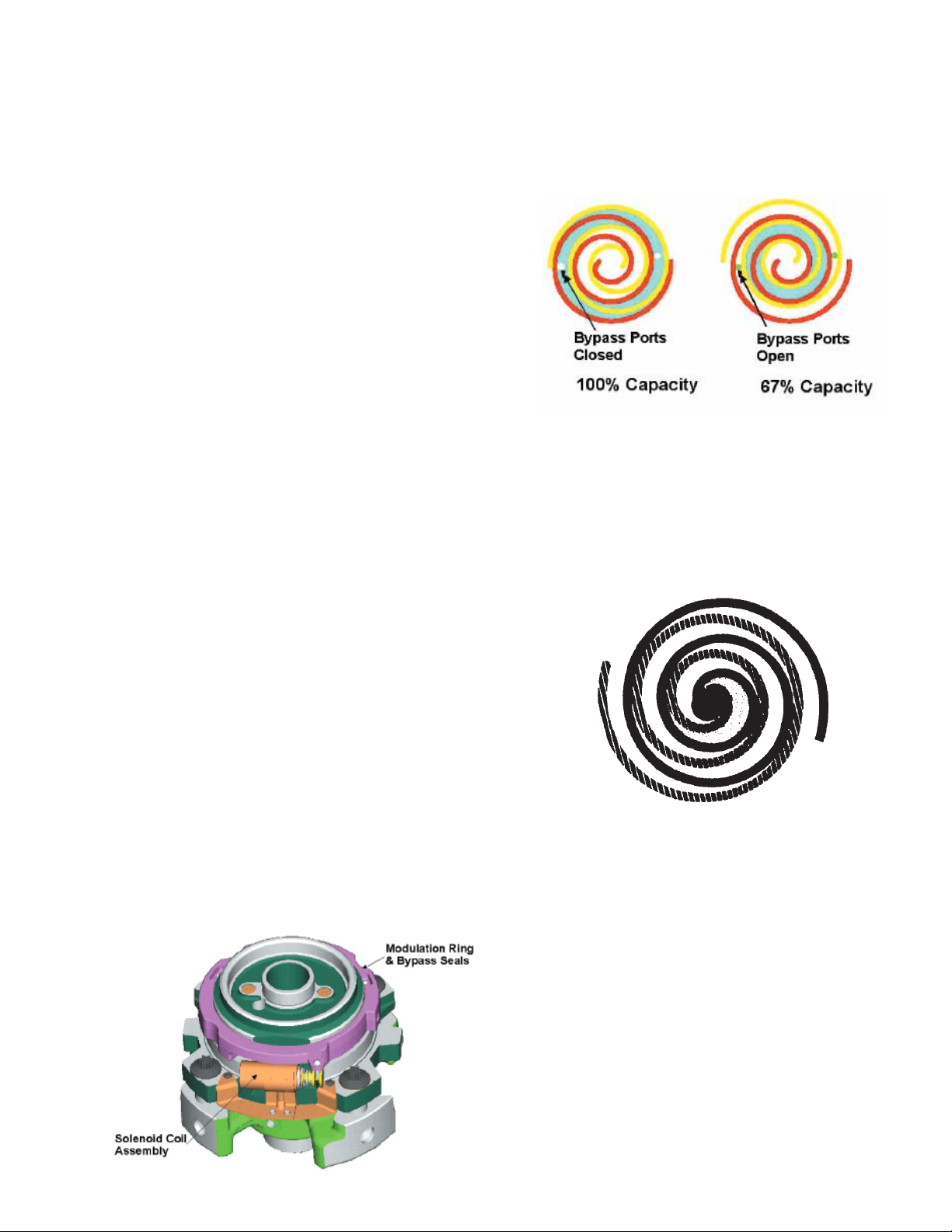
The ZPS two-step modulated scroll uses a single step of
unloading to go from full capacity to approximately 67%
capacity. A single speed, high efficiency motor continues to
run while the scroll modulates between the two capacity
steps.
FIGURE A
A scroll is an involute spiral which, when matched with a
mating scroll form as shown, generates a series of crescent
shaped gas pockets between the two members.
During compression, one scroll remains stationary (fixed
scroll) while the other form (orbiting scroll) is allowed to orbit
®
(but not rotate) around the first form.
As this motion occurs, the pockets between the two forms
are slowly pushed to the center of the two scrolls while
simultaneously being reduced in volume. When the pocket
reaches the center of the scroll form, the gas, which is now
at a high pressure, is discharged out of a port located at the
center.
During compression, several pockets are being compressed
simultaneously, resulting in a very smooth process. Both the
suction process (outer portion of the scroll members) and the
discharge process (inner portion) are continuous.
Some design characteristics of the Compliant Scroll compressor are:
• Compliant Scroll compressors are more tolerant of liquid
refrigerant.
NOTE: Even though the compressor section of a Scroll
compressor is more tolerant of liquid refrigerant, continued floodback or flooded start conditions may wash oil
from the bearing surfaces causing premature bearing
failure.
27
Page 28
PRODUCT DESIGN
• Compliant scroll compressors perform "quiet" shutdowns
that allow the compressor to restart immediately without
the need for a time delay. This compressor will restart
even if the system has not equalized.
NOTE: Operating pressures and amp draws may differ
from standard reciprocating compressors. This information can be found in the unit's Technical Information
Manual.
CAPACITY CONTROL - COMFORTNET
TM
MODELS
During the compression process, there are several pockets
within the scroll that are compressing gas. Modulation is
achieved by venting a portion of the gas in the first suction
pocket back to the low side of the compressor thereby
reducing the effective displacement of the compressor. See
Figure A. Full capacity is achieved by blocking these vents,
increasing the displacement to 100%. A solenoid in the
compressor, controlled by an external 24-volt ac signal,
moves the slider ring that covers and uncovers these vents.
The vent covers are arranged in such a manner that the
compressor operates somewhere around 67% capacity
when the solenoid is not energized and 100% capacity when
the solenoid is energized. The loading and unloading of the
two step scroll is done “on the fly” without shutting off the
motor between steps. See Figure C below. The unloaded
mode default was chosen for two reasons:
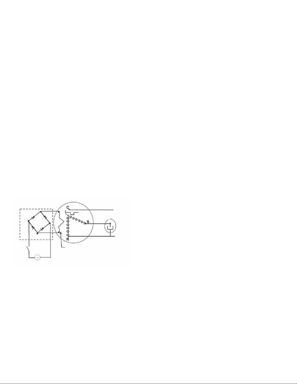
Molded Plug*
Line
Run Capacitor
Line
Internal Unloader
Coil
24 vdc
*Rectifier is integrated on the UC PC B
FIGURE C
1. It is expected that the majority of run hours will be in the
low capacity, unloaded mode.
2. It allows a simple two-stage thermostat to control capacity through the second stage in both cooling and possibly
heating if desired.
18 to 28 volt ac. The coil power requirement is 20 VA. The
external electrical connection is made with a molded plug
assembly. This plug is connected to the Communicating
Unitary Control PCB (UC PCB) which contains a full wave
rectifier to supply direct current to the unloader coil.
COILS AND BLOWER COILS
MBVC blower cabinets are designed to be used as a twopiece blower and coil combination and can be utilized with the
CAUF, CAPF and CAPT coils for upflow and downflow
applications. The CACF and CHPF coils are designed for
horizontal applications. This two-piece arrangement allows
for a variety of mix-matching possibilities providing greater
flexibility.
The MBVC blower cabinets use a variable speed motor that
maintains a constant airflow with a higher duct static. MBVC
blower cabinets are approved for applications with cooling
coils of up to 0.8 inches W.C. external static pressure. The
MBVC models allow airflow trimming of +/-10%.
All units are constructed with R-4.2 insulation. In areas of
extreme humidity (greater than 80% consistently), insulate
the exterior of the blower with insulation having a vapor barrier
equivalent to ductwork insulation, providing local codes
permit.
AVPTC Multi-Position Air Handler
AVPTC is a multi-position, variable-speed air handler used
with R-410A and are available in 2 to 5 ton sizes with optional
3 kW to 25kW electric heat kits available for field installation.
The AVPTC unit’s blower design includes a variable-speed
ECM motor and is compatible with heat pumps and variablecapacity cooling applications.
This appliance can be installed in the vertical or left horizontal
position without modification. The horizontal right and downflow
positions require product modification. This product is designed for zero inches (0 inches) clearance; however, adequate access for service or replacement must be considered without removing permanent structure. This unit can be
installed on a platform when deemed necessary.
In an attic installation a secondary drain pan must be provided
by the installer and placed under the entire unit with a
separate drain line properly sloped and terminated in an area
visible to the owner. This secondary drain pan is required in
the event that there is a leak or main drain blockage. Closed
cell insulation should be applied to the drain lines in unconditioned spaces where sweating may occur.
UNLOADER SOLENOID
A nominal 24-volt direct current coil activates the internal
unloader solenoid. The input control circuit voltage must be
28
Page 29

PRODUCT DESIGN
NOTE: AVPTC air handlers are factory-sealed to achieve a
2% or less leakage rate at 1.0" water gauge external duct
static pressure.
Communicating Unitary Control (UC) PCB
The Communicating System Unitary Control PCB is a microprocessor-based control for heat pump and air conditioning
condensing units with single-phase compressors up to 5 ton
capacity operating on standard residential or Delta and Wye
commercial power. The control incorporates the basic functionality of existing defrost controls, outdoor thermostats,
contactors, compressor staging controls, short cycle controls, line voltage monitors, Comfort Alert™ or CoreSense
Module (dependent upon which module you are using), two
speed condenser fan relays and the Active Protection component of enabled thermostats. The control is designed to
work as part of a fully communicating HVAC system with 4
wires. The control also supports legacy 24VAC thermostat
inputs for Y1, Y2, O and 24VAC outputs for RVS, W1, and L
for non-communicating systems. Outputs include compressor power, compressor stage select, and outdoor fan high
and outdoor fan low speed. System inputs include high/low
pressure switches, as well as thermistor inputs for outdoor
coil temperature and outdoor air temperature.
29
Page 30

SYSTEM OPERA TION
COOLING
The refrigerant used in the system is R-410A. It is a clear,
colorless, non-toxic and non-irritating liquid. R-410A is a
50:50 blend of R-32 and R-125. The boiling point at atmospheric pressure is -62.9°F.
A few of the important principles that make the refrigeration
cycle possible are: heat always flows from a warmer to a
cooler body. Under lower pressure, a refrigerant will absorb
heat and vaporize at a low temperature. The vapors may be
drawn off and condensed at a higher pressure and temperature to be used again.
The indoor evaporator coil functions to cool and dehumidify
the air conditioned spaces through the evaporative process
taking place within the coil tubes.
NOTE: The pressures and temperatures shown in the
refrigerant cycle illustrations on the following pages are for
demonstration purposes only. Actual temperatures and pressures are to be obtained from the "Expanded Performance
Chart".
Liquid refrigerant at condensing pressure and temperatures,
(270 psig and 122°F), leaves the outdoor condensing coil
through the drier and is metered into the indoor coil through
the metering device. As the cool, low pressure, saturated
refrigerant enters the tubes of the indoor coil, a portion of the
liquid immediately vaporizes. It continues to soak up heat and
vaporizes as it proceeds through the coil, cooling the indoor
coil down to about 48°F.
Heat is continually being transferred to the cool fins and tubes
of the indoor evaporator coil by the warm system air. This
warming process causes the refrigerant to boil. The heat
removed from the air is carried off by the vapor.
As the vapor passes through the last tubes of the coil, it
becomes superheated. That is, it absorbs more heat than is
necessary to vaporize it. This is assurance that only dry gas
will reach the compressor. Liquid reaching the compressor
can weaken or break compressor valves.
The compressor increases the pressure of the gas, thus
adding more heat, and discharges hot, high pressure superheated gas into the outdoor condenser coil.
In the condenser coil, the hot refrigerant gas, being warmer
than the outdoor air, first loses its superheat by heat transferred from the gas through the tubes and fins of the coil. The
refrigerant now becomes saturated, part liquid, part vapor and
then continues to give up heat until it condenses to a liquid
alone. Once the vapor is fully liquefied, it continues to give up
heat which subcools the liquid, and it is ready to repeat the
cycle.
HEATING
The heating portion of the refrigeration cycle is similar to the
cooling cycle. By energizing the reversing valve solenoid coil,
the flow of the refrigerant is reversed. The indoor coil now
becomes the condenser coil, and the outdoor coil becomes
the evaporator coil.
The check valve at the indoor coil will open by the flow of
refrigerant letting the now condensed liquid refrigerant bypass the indoor expansion device. The check valve at the
outdoor coil will be forced closed by the refrigerant flow,
thereby utilizing the outdoor expansion device.
COOLING CYCLE
For communicating room thermostat: When the room thermostat calls for either low stage cool or high stage cool,
appropriate commands are sent via the data 1 and data 2 lines
to the outdoor unit's UC control. The UC control energizes the
on-board compressor relay and the on-board outdoor fan
relay. The compressor high stage solenoid is energized if it
is a high stage call.
The UC control sends a fan command to the indoor unit (air
handler or furnace). The indoor unit operates the indoor
blower at the appropriate airflow level. The system operates
at the cooling level demanded by the thermostat.
When the thermostat is satisfied, appropriate commands are
sent to the UC control. The compressor relay and outdoor
fan relay is de-energized. The compressor high stage
solenoid is de-energized if it was energized. The UC control
sends an appropriate command to the indoor unit to deenergize the indoor blower motor.
If room thermostat fan status is set to be “on”, then indoor
blower would run continuously rather than cycling with the
compressor.
For heat pumps, the reversing valve is energized during the
cooling cycle. The call for cooling from the communicating
thermostat indicates to the control that the reversing valve is
to be energized during cooling operation.
HEATING CYCLE
For communicating room thermostat: When the room thermostat calls for either low stage heat or high stage heat,
appropriate commands are sent via the data 1 and data 2 lines
to the outdoor unit's UC control. The UC control energizes the
on-board compressor relay and the on-board outdoor fan
relay. The compressor high stage solenoid is energized if it
is a high stage call. The UC control sends a fan command
to the indoor unit (air handler or furnace). The indoor unit
operates the indoor blower at the appropriate airflow level.
The system operates at the cooling level demanded by the
thermostat.
When the thermostat is satisfied, appropriate commands are
sent to the UC control. The compressor relay and outdoor
fan relay is de-energized. The compressor high stage
solenoid is de-energized if it was energized. The UC control
sends an appropriate command to the indoor unit to deenergize the indoor blower motor.
30
Page 31

SYSTEM OPERA TION
DEFROST CYCLE - COMFORTNETTM MODELS
The defrosting of the outdoor coil is jointly controlled by the
UC PCB and the outdoor coil temperature (OCT) sensor.
The OCT sensor is clamped to a feeder tube entering the
outdoor coil. Defrost timing periods of 30, 60, 90 or 120
minutes may be selected via the dipswitch settings on the UC
PCB. In a communicating system, the defrost timing periods
can also be selected in the communicating thermostat user
menu. During operation, if the coil temperature is low enough
(approximately 31° F), the microprocessor will accumulate
the compressor run time. When the total compressor run
time reaches 30, 60, 90 or 120 minutes, and there is a call for
heat, the PCB will initiate a defrost cycle. When the
microprocessor detects the coil temperature to be high
enough (approximately 75 0F), or 10 minutes of maximum
defrost cycle time has elapsed, whichever occurs first, the
defrost cycle is terminated and the timing period is reset. The
field service personnel can also advance a heat pump to the
defrost cycle by simultaneously pressing the “TEST” button
and the “RECALL” button on the UC board.
Use the dipswitches to select defrost time interval (30, 60, 90
or 120 minutes) See chart below
31
Page 32

SYSTEM OPERA TION
COOLING CYCLE
Reversing Va lve
(Energized)
Indoor
Coil
HEATING CYCLE
Outdoor
Coil
Accumulator
Thermostatic
Expansion
Valve
Bi-Flow
Filter Dryer
Check Valve
32
Indoor
Coil
Reversing Va lve
(De-Energized)
Outdoor
Coil
Accumulator
Thermostatic
Expansion
Valve
Bi-Flow
Filter Dryer
Check Valve
Page 33

SYSTEM OPERA TION
EXPANSION VALVE/CHECK VALVE ASSEMBLY
IN COOLING OPERATION
Most expansion valves used in current Goodman/Amana
use an internally checked expansion valve.
This type of expansion valve does not require an external check valve as shown above.
However, the principle of operation is the same.
EXPANSION VALVE/CHECK VALVE ASSEMBLY
IN HEATING OPERATION
®
Brand Heat Pump products
33
Page 34

TROUBLESHOOTING CHART
COOLING/HP ANALYSIS CHART
Com plaint
PO SSIBLE CAUS E
DOTS IN ANALYSIS
GUIDE INDICATE
"POS S I BLE CAUS E"
Pow er Failure
Blow n Fuse
Loose Connection
Shorted or Broken Wires
Open Fan Overload
Faulty Thermostat
Faulty Transf ormer
Shorted or Open Capacitor
Internal Compressor Overload Open
Shorted or Grounded Compressor
Compressor Stuck
Faulty Compressor Contactor
Faulty Fan Relay
Open Control Circuit
Low Voltage
Faulty Evap. Fan Motor
Shorted or Grounded Fan Motor
Improper Cooling Anticipator
Shortage of Refrigerant
Restric ted Liquid Line
Open Element or Limit on Elec. Heater
Dirt y Air Filter
Dirty Indoor Coil
Not enough air across Indoor Coil
Too much air across Indoor Coil
Overcharge of Refr igerant
Dirty Outdoor Coil
Noncondensibles
Recirculation of Condens ing Air
Infiltration of Outdoor Air
Improperly Located Thermostat
Air Flow Unbalanced
System Undersized
Broken Internal Parts
Broken Valves
Inefficient Compressor
Wrong Type Expans ion Valve
Expansion Device Restricted
Oversized Expansion Valve
Undersized Expansion Valve
Expansion Valve Bulb Loose
Inoperative Expansion Valve
Loose Hold-dow n Bolts
Faulty Reversing Valve
Faulty Defros t Control
Faulty Defros t Thermostat
Flow rator Not Seating Properly
No Coolin g
SYMPTOM
System will not start
Compressor will not start - fan runs
Comp. and Cond. Fan will not start
Eva porator fan will not start
Condenser fan will not start
Compressor runs - goes off on overload
Compressor cycles o n overload
Unsatisfactory
Cooling/Heating
System runs continuously - little cooling/htg
Too cool and then too warm
•
•••
•••
••••••
••
••• •
••
• ••••
•
••
•••
•••
•
•
•••
••
••
••
••
•• •• •
♦♦
••• •
••• •
••• •
•• •
•• •
••
•• •
•••
••
••
••
•• ••
•
••• • ••
••• • •• •
••
••• • •
•• •
•
•
• Cooling or Heat ing Cycle (Heat Pump)
•••
System
Ope rating
Pressures
Not cool enough on warm days
Certain areas too cool, others too warm
Compressor is no isy
System runs - blows cold air in heating
Unit will not terminate de frost
Unit will not defrost
Low suction pr essure
Low head pressure
High suction pressure
High head pressure
♦
♦
♦
♦
♦
♦
♦
•
♦
••
♦
♦
••
♦
♦
♦
•
••
•
•
♦
••
•
♦♦♦ ♦♦♦
♦♦♦♦♦ ♦
♦♦♦♦♦♦♦
Heating Cycle Only (He a t Pum p)
♦
Test Method
Rem edy
See Service Procedure Ref.
Test Voltage S-1
Inspect Fuse Size & Type S-1
Inspect Connection - Tighten S-2, S-3
Test Circuits W ith Ohmmeter S-2, S-3
Test Continuity of Overload S-17A
Test Continuity of Thermos tat & Wiring S-3
Check Control Cir cuit with Voltmeter S-4
Test Capacitor S-15
Test Continuity of Overload S-17A
Test Motor Windings S-17B
Use Tes t Co rd S-1 7D
Tes t Continuity of Coi l & Contacts S-7, S - 8
Test Continuity of Coil And Contacts S-7
Test Control Circuit w ith Voltmeter S-4
Test Voltage S-1
Repair or Replac e S-16
Test Motor Windings S-16
Check Resistance of Anticipator S-3B
Test For Leaks, A dd Refrigerant S-101,103
Remove Restriction, Replace Restricted Part S-112
Test Heater Element and Controls S-26,S-27
Inspect Filter-Clean or Replace
Inspect Coil - Clean
Check Blow er Speed, Duct Static Press, Filter S-200
Reduce Blow er Speed S-200
Recover Part of Charge S-113
Inspect Coil - Clean
Recover Charge, Evacuate, Recharge S-114
Remove Obstruction to Air Flow
Check Window s, Doors, Vent Fans, Etc.
Relo c ate Thermostat
Readjust A ir V olume Dampers
Refigure Cooling Load
Replace Compressor S-115
Test Compressor Eff iciency S-104
Test Compressor Eff iciency S-104
Replace Valve S-110
Remove Restriction or Replace Expansion Device S-110
Replace Valve
Replace Valve
Tighten Bulb Bracket S-105
Check V alv e Ope ration S-110
Tighten Bolts
Replace Valve or Solenoid S-21, 122
Test Contr ol S-24
Test Defrost Thermostat S-25
Check Flowrator & Seat or Replace Flow rator S-111
34
Page 35

SERVICING TABLE OF CONTENTS
S-1 CHECKING VOLT AGE ................................................ 35
S-2 CHECKING WIRING ................................................... 35
S-3E CTK0*** COMFORTNETTM THERMOST A T..............35
S-4 CHECKING TRANSFORMER
AND CONTROL CIRCUIT ......................................48
S-6 CHECKING TIME DELAY RELA Y ...............................48
S-8A CHECKING UNITARY (UC) CONTROL
COMPRESSOR CONT ACTOR/RELA Y
CONTACTS .............................................................48
S-9 CHECKING HIGH AND LOW VOLT AGE
TO ECM MOTOR..........................................................49
S-10A COPELAND COMFORT ALER T™..............................49
S-12 CHECKING HIGH PRESSURE CONTROL...............63
S-13 CHECKING LOW PRESSURE CONTROL................63
S-14 CHECKING HIGH AND LOW PRESSURE SWITCH
VOLTAGE .................................................................63
S-15 CHECKING CAP ACITOR ...........................................63
S-15A RESISTANCE CHECK USING A DIGIT AL
MULTI-METER.........................................................63
S-15B CAPACITANCE CHECK USING A DIGIT AL
MUL TI-METER (IN CAP ACIT ANCE MODE).............64
S-16G CHECKING EMERSON ULTRATECH™
ECM MOTORS ........................................................64
S-16H ECM CFM ADJUSTMENTS A VPTC/MBVC .................67
S-17 CHECKING COMPRESSOR ..................................... 75
S-17A RESIST ANCE TEST...................................................75
S-17B GROUND TEST .........................................................75
S-17C UNLOADER TEST PROCEDURE ............................ 76
S-17D OPERA TION TEST.................................................... 77
S-18 TESTING CRANKCASE HEATER
(OPTIONAL ITEM) ...................................................77
S-21 CHECKING REVERSING V AL VE
AND SOLENOID .....................................................77
S-24 TESTING DEFROST CONTROL................................77
S-26 TESTING TEMPERA TURE SENSORS
(COMFORTNET READY MODELS ONL Y) .............78
S-40A AVPTC/MBVC ELECTRONIC
BLOWER/HEA TER CONTROL...............................78
S-60 ELECTRIC HEA TER (OPTIONAL ITEM) .................... 83
S-61A CHECKING HEATER LIMIT CONTROL(S) ................84
S-61BCHECKING HEATER FUSE LINK..............................84
(OPTIONAL ELECTRIC HEA TERS) ....................... 84
S-62 CHECKING HEA TER ELEMENTS ............................. 84
S-100 REFRIGERATION REP AIR PRACTICE..................... 84
S-101 LEAK TESTING
(NITROGEN OR NITROGEN-TRACED) ................ 85
S-102 EV
S-103 CHARGING.................................................................86
S-104 CHECKING COMPRESSOR EFFICIENCY................87
S-106 OVERFEEDING ..........................................................87
S-107 UNDERFEEDING ....................................................... 87
S-108 SUPERHEAT .............................................................. 87
S-109 CHECKING SUBCOOLING........................................87
S-1 10 CHECKING EXP ANSION V AL VE OPERA TION..........88
S-112 CHECKING RESTRICTED LIQUID LINE .................. 88
S-113 OVERCHARGE OF REFRIGERANT ..........................88
S-114 NON-CONDENSABLES ............................................. 88
S-115 COMPRESSOR BURNOUT .......................................91
S-120 REFRIGERANT PIPING .............................................91
S-203 SINGLE PIECE AIR HANDLER EXTERNAL
S-203A TWO PIECE AIR HANDLER EXTERNAL
ACUA TION .............................................................85
STATIC PRESSURE............................................92
STATIC PRESSURE............................................92
35
Page 36

SERVICING
S-1 CHECKING VOLTAGE
1. Remove outer case, control panel cover, etc., from unit
being tested.
With power ON:
WARNING
Line Voltage now present.
2. Using a voltmeter, measure the voltage across terminals
L1 and L2 of the contactor for the condensing unit or at the
field connections for the air handler or heaters.
ComfortNetTM Ready Condensing Units: Measure the
voltage across the L1 and L2 lugs on the unitary (UC)
control.
3. No reading - indicates open wiring, open fuse(s) no power
or etc., from unit to fused disconnect service. Repair as
needed.
4. With ample voltage at line voltage connectors, energize
the unit.
5. Measure the voltage with the unit starting and operating,
and determine the unit Locked Rotor Voltage. NOTE: If
checking heaters, be sure all heating elements are
energized.
Locked Rotor Voltage is the actual voltage available at
the compressor during starting, locked rotor, or a stalled
condition. Measured voltage should be above minimum
listed in chart below.
To measure Locked Rotor Voltage attach a voltmeter to
the run "R" and common "C" terminals of the compressor,
or to the T1 and T2 terminals of the contactor. Start the unit
and allow the compressor to run for several seconds, then
shut down the unit. Immediately attempt to restart the
unit while measuring the Locked Rotor Voltage.
ComfortNet Ready Condensing Units: To measure the
Locked Rotor Voltage, attach a voltmeter to the run "R"
and common "C" terminals of the compressor or across
the "R" and "C" lugs on the unitary (UC) control. Start the
unit and allow the compressor to run for several seconds,
then shut down the unit. Immediately attempt to restart
the unit while measuring the Locked Rotor Voltage.
6. Locked rotor voltage should read within the voltage tabulation as shown. If the voltage falls below the minimum
voltage, check the line wire size. Long runs of undersized
wire can cause low voltage. If wire size is adequate, notify
the local power company in regard to either low or high
voltage.
Unit Supply Voltage
Voltage Min. Max
208/230 197 253
460 414 506
NOTE: When operating electric heaters on voltages other
than 240 volts, refer to the System Operation section on
electric heaters to calculate temperature rise and air flow.
Low voltage may cause insufficient heating.
S-2 CHECKING WIRING
HIGH VOLTAGE!
Disconnect ALL power before servicing
or installing. Multiple power sources
may be pr es ent. Fa ilur e to do s o ma y
cause pro pe rty dam age , pe rs onal in jury
or death.
1. Check wiring visually for signs of overheating, damaged
insulation and loose connections.
2. Use an ohmmeter to check continuity of any suspected
open wires.
3. If any wires must be replaced, replace with comparable
gauge and insulation thickness.
S-3E CTK0*** COMFORTNETTM THERMOSTAT
COMFORTNET™ SYSTEM
The ComfortNet system (or CT system) is a system that
includes a ComfortNet compatible air handler/furnace/modular blower and air conditioner or heat pump with a CTK0*
thermostat. Any other system configurations are considered
invalid ComfortNet systems and must be connected as a
tradition (or legacy) system. The table below compares the
valid CT systems.
CT compatible Air Handler or
Modular Blo w er
CT compatible Air Handler or
Modular Blo w er
A ComfortNet heating/air conditioning system differs from a
legacy/traditional system in the manner in which the indoor
unit, outdoor unit and thermostat interact with one another. In
a traditional system, the thermostat sends commands to the
indoor and outdoor units via analog 24 VAC signals. It is a
one-way communication path in that the indoor and outdoor
units typically do not return information to the thermostat.
On the other hand, the indoor unit, outdoor unit, and thermostat comprising a ComfortNet system “communicate” digitally with one another. It is now a two-way communications
path. The thermostat still sends commands to the indoor and
outdoor units. However, the thermostat may also request and
receive information from both the indoor and outdoor units.
This information may be displayed on the CT thermostat. The
indoor and outdoor units also interact with one another. The
outdoor unit may send commands to or request information
from the indoor unit. This two-way digital communications
CT compatible
Air Conditioner
CT compatible
Heat Pump
Full CT system
benefits & features
Full CT system
benefits & features
36
Page 37

SERVICING
between the thermostat and subsystems (indoor/outdoor
unit) and between subsystems is the key to unlocking the
benefits and features of the ComfortNet system.
Two-way digital communications is accomplished using
only two wires. The thermostat and subsystem controls are
powered with 24 VAC Thus, a maximum of 4 wires between
the equipment and thermostat is all that is required to operate
the system.
AIRFLOW CONSIDERATIONS
Airflow demands are managed differently in a fully communicating system than they are in a legacy wired system. The
system operating mode (as determined by the thermostat)
determines which unit calculates the system airflow demand.
If the indoor unit is responsible for determining the airflow
demand, it calculates the demand and sends it to the ECM
motor. If the outdoor unit or thermostat is responsible for
determining the demand, it calculates the demand and
transmits the demand along with a fan request to the indoor
unit. The indoor unit then sends the demand to the ECM
motor. The following table lists the various ComfortNet™
systems, the operating mode, and airflow demand source.
For example, assume the system is an air conditioner
matched with an air handler. With a call for low stage cooling,
the air conditioner will calculate the system’s low stage
cooling airflow demand. The air conditioner will then send a
fan request along with the low stage cooling airflow demand
to the air handler. Once received, the air handler will send the
low stage cooling airflow demand to the ECM motor. The
ECM motor then delivers the low stage cooling airflow. The
table below lists the nominal high and low stage airflow for the
ComfortNet air conditioners and heat pumps.
CONTROL WIRING
NOTE: Refer to section Electrical Connections - High
Voltage Connections for 208/230 volt line connections to
the air conditioner or heat pump.
NOTE: A removable plug connector is provided with the
control to make thermostat wire connections. This plug
may be removed, wire connections made to the plug, and
replaced. It is
strongly recommended that you do not
connect multiple wires into a single terminal. Wire nuts
are recommended to ensure one wire is used for each
terminal. Failure to do so may result in intermittent
operation.
Typical 18 AWG thermostat wire may be used to wire the
system components. 150 feet is the maximum length of wire
recommended between indoor unit and outdoor unit, or
between indoor unit and thermostat.
CTK04 STANDARD WIRING SCHEME:
Two wires may be utilized between the indoor and outdoor
units. For this wiring scheme, only the data lines, 1 and 2,
are required between the indoor and outdoor units. A 40VA,
208/230 VAC to 24 VAC transformer must be installed in the
outdoor unit to provide 24 VAC power to the outdoor unit’s
electronic control. The “C” 24v common of the outdoor
transformer should be grounded to the equipment (earth)
ground. The transformer is included with the CTK0* kit. See
kit instructions for mounting and wiring instructions. Four
wires are required between the indoor unit and thermostat.
12RC
Thermostat
Models
*SZC160241 800 600 800 600
*SZC160361 1200 800 1200 800
*SZC160481 1550 1100 1550 1100
*SZC160601 1800 1210 1800 1210
*SZC180241 850 550 850 550
*SZC180361 1250 850 1250 850
*SZC180481 1750 1210 1750 1210
*SZC180601 1750 1210 1750 1210
Cooling Heating
High Low High Low
40VA Transformer (included in
CTK04 kit)
208/230 VAC
24 VAC
12RC
12RC
Note
: Recommended (Field Provided)
System Wiring
Air Handler/Furnace/PCB
AC/HP/ PCB
(Ground Indicator)
37
Page 38

SERVICING
g
(
1
2R
12RC
40VA Transformer
CTK0*** kit)
208/230 VAC
and Four Wires between Air Handler and Thermostat
included in
12
24 VAC
CTK04 System Wiring Using Three-Wires
between Air Handler and AC / HP
CTK 04 ALTERNATE WIRING SCHEME:
Three wires should be utilized between the indoor and outdoor
units. For this wiring scheme, two wires for the data lines, 1
and 2 are required and a wire connecting the common “C”
terminals between the indoor and outdoor units. This connects both commons to the same ground potential allowing
for better communication. A 40VA, 208/230 VAC to 24 VAC
transformer must be installed in the outdoor unit to provide
24 VAC power to the outdoor unit’s electronic control. The
transformer is included with the CTK0* kit. See kit instructions for mounting and wiring instructions. Four wires are
required between the indoor unit and thermostat.
C
RC
Thermostat
Modular Blower
Inte
rated Control Module
AC/H P Integrate d
Control Module
COMFORTNET™ SYSTEM ADVANCED FEATURES
The ComfortNet™ system permits access to additional
system information, advanced setup features, and advanced
diagnostic/troubleshooting features. These advanced features are organized into a menu structure. Refer to the
Installation and Start-Up instructions shipped with your
particular CTKO*** thermostat.
Diagnostics
Accessing the air handler’s diagnostics menu provides ready
access to the last six faults detected by the air handler.
Faults are stored most recent to least recent. Any consecutively repeated fault is stored a maximum of three times.
Example: A clogged return air filter causes the air handler’s
motor to repeatedly enter a limiting condition. The control will
only store this fault the first three consecutive times the fault
occurs.
NOTE: It is highly recommended that the fault history be
cleared after performing maintenance or servicing the air
handler.
38
Page 39

SERVICING
Network Troubleshooting
The ComfortNet™ system is a fully communicating system,
and thus, constitutes a network. Occasionally the need to
troubleshoot the network may arise. The integrated air
handler control has some on-board tools that may be used
to troubleshoot the network. These tools are: red communications LED, green receive (Rx) LED, and learn button.
Refer to the Communications Troubleshooting Chart and Air
Handler Diagnostic Codes below for error codes, possible
causes and corrective actionS.
COMMUNICATIONS TROUBLESHOOTING CHART
LED LED
Status
Off
1 Flash
Red
Communications
LED
2 Flashes
Off
1 Steady
Flash
Green Receive
LED
Rapid
Flashing
On Solid
Indication Possible Causes Corrective Action(s) Notes & Cautions
x Normal condition x None x None x None
x Communications
Failure
x Out-of-box reset x Control power up
x No power
x Communications
error
x No network found x Broken/ disconnected
x Normal network
traffic
x Data 1/ Data 2
miss-wire
x Communications
Failure
x Learn button
depressed
x No power to air
handler
x Open fuse
x Communications error
data wire(s)
x Air handler is installed
as a noncommunicating/
traditional system
x Control is “talking” on
network as expected
x Data 1 and data 2
wires reversed at air
handler, thermostat,
or ComfortNet™
compatible outdoor
AC/HP
x Short between data 1
and data 2 wires
x Short between data 1
or data 2 wires and R
(24VAC) or C (24VAC
common)
• Red communications LED – Indicates the status of the
network. The table below indicates the LED status and the
corresponding potential problem.
• Green receive communication LED – Indicates network
traffic. The table below indicates the LED status and the
corresponding potential problem.
• Learn button – Used to reset the network. Depress the
button for approximately 2 seconds to reset the network.
x Depress Learn Button
x Verify that bus BIAS
and TERM
dipswitches are in the
ON position.
x None x None
x Check fuses and
circuit breakers;
replace/reset
x Replace blown fuse
x Check for shorts in
low voltage wiring in
air handler/system
x Reset network by
depressing learn
button
x Check data 1/ data 2
voltages
x Check
communications
wiring (data 1/ data 2
wires)
x Check wire
connections at
terminal block
x Verify air handler
installation type (noncommunicating/
traditional or
communicating)
x Check data 1/ data 2
voltages
x None x None
x Check
communications
wiring (data 1/ data 2
wires)
x Check wire
connections at
terminal block
x Check data 1/ data 2
voltages
x Depress once
quickly for a powerup reset
x Depress and hold
for 2 seconds for
an out-of-box reset
x Turn power OFF
prior to repair
x Turn power OFF
prior to repair
x Verify wires at
terminal blocks are
securely twisted
together prior to
inserting into
terminal block
x Verify data1 and
data voltages as
described above
x Turn power OFF
prior to repair
x Verify wires at
terminal blocks are
securely twisted
together prior to
inserting into
terminal block
x Verify data1 and
data voltages as
described above
39
Page 40

SERVICING
7 S E GME NT LED
(characters will alternate)
( n o d i s p l a y) INTE R NAL CONTRO L FAULT / NO PO WER
On STANDBY, WAITING FOR INP UTS
Ec HEATER KIT TOO LARGE, TOO SMALL , OR NO MATCH
E5 FUSE O PE N
EF A UXIL IARY SWITCH OP EN
d0 DATA NOT ON NETWORK
d1 INVALID DATA ON N E TW O RK
d4 INVALID ME MORY CARD DATA
b0 BLOWER MOTOR NOT RUNNING
b1 BLOW E R MO TOR COMMUNICAT ION E R R O R
b2 BLOWER MOTOR HP MISMATCH
b3
b4 BLOWER MOTOR CURRE NT TRIP OR LOST ROTOR
b5 BLOWER MOTOR ROTOR LOCKED
b6 OVER/UNDER VOLTAGE TRIP OR OVER TEMPERATU RE TRI P
b7 INCOMPLETE PARAMETER SENT TO MOTOR
b9 LOW INDOOR AIRFLOW
C1 LOW STAGE COOL - LEGACY MODE ONLY
C2 HIGH STAGE COOL - LEGACY MODE ONLY
P1 L OW ST A GE HEAT PUMP HEAT - LEGACY MOD E ONLY
P2 HIGH STAGE HEAT PUMP HEAT - LEGACY MODE ONLY
h 1 EM ERG E NCY HEAT LOW - COM MUNIC A TING MODE ONL Y
h 2 EMERG E NC Y HEAT HIGH - CO M MUNICATING MOD E ONLY
F C FAN COOL - COMM UNICATING MO D E ONLY
F H FAN HEAT - COMMUNICATING MOD E ONLY
FFAN ONLY
H1 ELECTRIC HEAT LOW
H2 ELECTRIC HEAT HIGH
dF
BLOWER MOTOR OPERATING IN POWER, TEMP., OR SPEED
LIMIT
DEFROST - COMMUNICATING MODE ONLY
(Not e: d efro st is di s pla y e d as H1 in a lega c y setu p)
DES CRIPTION OF CONDITION
40
GREE N CFM LED - EA CH FLASH REP RES ENTS 100CFM (USE FOR AIRFLOW APPRO XIMATIO N
ONLY) - EXAMPLE: 8 FLASHES = 800CFM
0140A00070-A
Page 41

SERVICING
Notes & Cautions
PCBJA101- PCBJA102 AIR HANDLER DIAGNOSTIC CODES
Corrective Actions
Possible Causes
ComfortNet ™
Thermostat Only
x Normal operation x None x Normal operation
None None
Message Code
model.
x Turn power OFF prior to repair.
x Use memory card for the specific
settings
x Verify electric heat dipswitch
x Verify the installed electric
dipswitches is too large for heater
kits in shared data set
x Heater kit selected via
Ec
LARGE
HTR TOO
turning power ON. Memory card
x Insert memory card BEFORE
heater is valid for the air handler.
Check nameplate or
model.
turning power ON. Memory card
may be removed after data is
loaded.
memory card.
may be removed after data is
loaded.
memory card.
data is loaded.
x Turn power OFF prior to repair.
x Use memory card for the specific
settings
x Verify electric heat dipswitch
x Verify the installed electric
dipswitches is too small for heater
kits in shared data set
x Heater kit selected via
Ec
SMALL
HTR TOO
x Insert memory card BEFORE
heater is valid for the air handler.
x Turn power OFF before removing
x Error code will be cleared once
Specification Sheet applicable to
your model* for allowable heater
kit(s).
for the specific model. Re-
populate data using correct
memory card if required.
x Verify shared data set is correct
x
Check nameplate or
Specification Sheet applicable to
your model* for allowable heater
kit(s).
x Turn power OFF before removing
x Verify shared data set is correct
for the specific model. Re-
populate data using correct
x Error code will be cleared once
data is loaded.
x Turn power OFF prior to repair.
memory card if required.
x Verify electric heat dipswitch
x Heater kit selected via
Ec
NO HTR
model.
x Use memory card for the specific
settings
x Verify the installed electric
dipswitches is doesn’t match
heater kits in shared data set
MATCH
turning power ON. Memory card
x Insert memory card BEFORE
heater is valid for the air handler.
Check nameplate or
may be removed after data is
loaded.
memory card.
data is loaded.
x Turn power OFF before removing
x Error code will be cleared once
Specification Sheet applicable to
your model* for allowable heater
kit(s).
for the specific model. Re-
populate data using correct
x Verify shared data set is correct
x Turn power OFF prior to repair.
x Replace fuse with 3-amp
voltage wiring
memory card if required.
x Short in low voltage wiring x Locate and correct short in low
Not
Displayed
Not
Displayed
automotive type
module fuse with 3A automotive
fuse.
x Turn power OFF prior to repair.
x Replace integrated control
power to air handler and
integrated control module.
x Assure 208/230 volt and 24 volt
x Check integrated control module
24 volt wire improperly
connected or loose
x Manual disconnect switch OFF or
x Blown fuse or circuit breaker
EE
FAULT
INTERNAL
x Replace integrated control
fuse (3A). Replace if necessary.
x Integrated control module has an
module with correct replacement
x Check for possible shorts in
internal fault
part
Discharge” section of manual.
x Read precautions in “Electrostatic
208/230 volt and 24 volt circuits.
Repair as necessary.
x Replace bad integrated control
module.
Fault Description
LED Codes
Diagnostic/Status
Symptoms of Abnormal Operation
(Communicating & Non-communicating
dipswitches is too large
for heater kits specified
x Normal operation
x Heater kit selected via
in shared data set
x Heater kit selected via
dipswitches is too small
for heater kits specified
in shared data set
x Heater kit selected via
dipswitches does not
heater kits specified in
shared data set
x Open Fuse
to air handler or no 24
volt power to integrated
control module
breaker
module has an internal
x No 208/230 volt power
x Blown fuse or circuit
fault.
x Integrated control
ON
1 Flash
1 Flash
1 Flash
5 Flashes
None
Thermostat)
W1 or Auxiliary/Emergency heat
provides the indicated error code.
icon illuminated
x LED display is ON continuously
x Electric heaters fail to energize on a call for
x Integrated control module LED display
x ComfortNet thermostat “Call for Service”
Handler” message
x ComfortNet thermostat scrolls “Check Air
x Electric heat airflow is higher than
expected on a call for W1 or
Auxiliary/Emergency heat
provides the indicated error code.
x Integrated control module LED display
x Electric heat airflow is higher than
expected on a call for W1 or
Auxiliary/Emergency heat
provides the indicated error code.
x Integrated control module LED display
provides the indicated error code.
Power”
provides no signal.
icon illuminated
x No air handler operation.
x Integrated control module LED display
x ComfortNet thermostat displays “Battery
x Air handler fails to operate
x Integrated control module LED display
x ComfortNet thermostat “Call for Service”
Handler” message
x ComfortNet thermostat scrolls “Check Air
41
Page 42

SERVICING
PCBJA101- PCBJA102 AIR HANDLER DIAGNOSTIC CODES
Notes & Cautions
repair
specific model.
BEFORE turning power
ON. Memory card may be
removed after data is
loaded.
x Turn power OFF prior to
x Use memory card for the
x Insert memory card
x Turn power OFF before
removing memory card.
x Error code will be cleared
repair
specific model.
BEFORE turning power
ON. Memory card may be
removed after data is
loaded.
removing memory card.
once data is loaded.
x Turn power OFF prior to
x Use memory card for the
x Insert memory card
x Turn power OFF before
x Error code will be cleared
once data is loaded.
Corrective Actions
for the specific model. Re-
populate data using correct
x Populate shared data set using
memory card.
memory card if required.
x Verify shared data set is correct
Possible Causes
has been rejected by integrated
shared data.
x Air handler does not contain any
d0
x Shared data set on memory card
d4
control module
ComfortNet ™
Thermostat Only
Fault Description
LED Codes
Diagnostic/Status
NO NET
Message Code
x Data not yet on network.
9 Flashes
Thermostat)
DATA
INVALID
MC DATA
data.
x Invalid memory card
11 Flashes
Symptoms of Abnormal Operation
42
provides indicated error code.
icon illuminated.
(Communicating & Non-communicating
x Air handler fails to operate.
x Integrated control module LED display
x ComfortNet thermostat “Call for Service”
Handler” message.
x ComfortNet thermostat scrolls “Check Air
operation.
provides indicated error code.
icon illuminated.
x Operation different than expected or no
x Integrated control module LED display
x ComfortNet thermostat “Call for Service”
Handler” message.
x ComfortNet thermostat scrolls “Check Air
Page 43

SERVICING
PCBJA101- PCBJA102 AIR HANDLER DIAGNOSTIC CODES
Notes & Cautions
repair
with correct replacement
x Replace circulator motor
part.
x Turn power OFF prior to
x Turn power OFF prior to
repair
with correct replacement
part.
x Replace circulator motor
x Replace integrated control
module with correct
replacement part.
x Turn power OFF prior to
repair
replacement part.
specific model
BEFORE turning power
ON. Memory card may be
removed after data is
loaded.
x Replace motor with correct
x Use memory card for the
x Insert memory card
x Turn power OFF before
removing memory card.
x Error code will be cleared
once shared data and
motor horse power match.
x Turn power OFF prior to
repair.
x Turn power OFF prior to
repair.
Corrective Actions
connection.
Replace if necessary.
connection.
x Tighten or correct wiring
Replace if necessary.
x Check circulator blower motor.
x Tighten or correct wiring
Replace if necessary.
x Check circulator blower motor.
x Check integrated control module.
x Verify circulator blower motor
horse power is the same
specified for the specific air
handler model. Replace is
necessary.
for the specific model. Re-
populate data using correct
memory card if required.
x Verify shared data set is correct
x Check filters for blockage.
Clean filters or remove
obstruction.
Remove obstruction. Verify all
registers are fully open.
sized for system. Resize/replace
ductwork if necessary.
installation requirements.
grills/registers, duct system, and
air handler/coil air inlet/outlet for
x Check ductwork for blockage.
x Verify ductwork is appropriately
x See "Installation Instructions" for
blockages.
x Check filters, filter
Possible Causes
circulator motor power leads or
circulator motor power leads
disconnected.
x Loose wiring connection at
b0
x Failed circulator blower motor.
x Loose wiring connection at
b1
circulator motor control leads.
x Failed circulator blower motor.
x Failed integrated control module.
b2
x Incorrect circulator blower motor
in air handler.
integrated control module.
x Incorrect shared data set in
x Blocked filters.
b3
change in speed or torque, sudden
blockage of air handler/coil air
inlet or outlet.
filters, very restrictive ductwork,
blockage of air handler/coil air
x Restrictive ductwork.
x Undersized ductwork.
x High ambient temperatures.
x Abnormal motor loading, sudden
b4
inlet or outlet.
x High loading conditions, blocked
ComfortNet ™
Thermostat Only
Fault Description
LED Codes
Diagnostic/Status
Message Code
Thermostat)
MOTOR
NOT RUN
is not running when it
should be running.
x Circulator blower motor
6 Flashes
COMM
MOTOR
module has lost
communications with
x Integrated control
6 Flashes
circulator blower motor.
MOTOR
MISMATCH
horse power in shared
data set does not match
x Circulator blower motor
6 Flashes
circulator blower motor
LIMITS
MOTOR
horse power.
x Circulator blower motor
6 Flashes
is operating in a power,
temperature, or speed
limiting condition.
TRIPS
MOTOR
senses a loss rotor
control.
x Circulator blower motor
6 Flashes
x Circulator blower motor
senses high current.
Symptoms of Abnormal Operation
provides indicated error code.
icon illuminated.
Handler” message.
provides indicated error code.
icon illuminated.
(Communicating & Non-communicating
x Air handler fails to operate.
x Integrated control module LED display
x ComfortNet thermostat “Call for Service”
x ComfortNet thermostat scrolls “Check Air
x Air handler fails to operate.
x Integrated control module LED display
x ComfortNet thermostat “Call for Service”
Handler” message.
x ComfortNet thermostat scrolls “Check Air
provides indicated error code.
icon illuminated.
x ComfortNet thermostat “Call for Service”
Handler” message.
x ComfortNet thermostat scrolls “Check Air
x Air handler fails to operate.
x Integrated control module LED display
performance.
x Air handler operates at reduced
provides b3 error code.
x Airflow delivered is less than expected.
x Integrated control module LED display
provides indicated error code.
icon illuminated.
x ComfortNet thermostat “Call for Service”
Handler” message.
x ComfortNet thermostat scrolls “Check Air
x Air handler fails to operate.
x Integrated control module LED display
43
Page 44

SERVICING
PCBJA101- PCBJA102 AIR HANDLER DIAGNOSTIC CODES
Notes & Cautions
repair
replacement part.
x Turn power OFF prior to
x Replace motor with correct
x Replace wheel with correct
replacement part.
x Turn power OFF prior to
repair.
x Turn power OFF prior to
repair.
replacement part(s).
x Replace with correct
x Use memory card for the
repair.
specific model.
x Turn power OFF prior to
Corrective Actions
Verify line voltage to blower is
within the range specified on the
air handler rating plate.
obstructions. Remove and
repair/replace wheel/motor if
necessary.
shaft rotation and motor.
Replace motor if necessary.
x Check circulator blower for
x Check power to air handler.
x Check circulator blower motor
installation requirements.
Verify control is populated with
correct shared data set. See data
x See "Installation Instructions" for
errors above for details.
x Check integrated control module.
x Check for locked rotor condition
(see error code above for
details).
x Check filters for blockage.
Clean filters or remove
obstruction.
Remove obstruction. Verify all
registers are fully open.
sized for system. Resize/replace
x Check ductwork for blockage.
ductwork if necessary.
x Verify ductwork is appropriately
Possible Causes
handler.
housing.
bearings.
x Obstruction in circulator blower
x Seized circulator blower motor
x Failed circulator blower motor.
b5
x High AC line voltage to air
b6
handler.
x Low AC line voltage to air
x High ambient temperatures.
x Error with integrated control
b7
module.
condition.
x Motor has a locked rotor
b9
x Blocked filters.
x Restrictive ductwork.
x Undersized ductwork.
ComfortNet ™
Thermostat Only
Fault Description
LED Codes
Diagnostic/Status
Symptoms of Abnormal Operation
(Communicating & Non-communicating
ROTOR
Message Code
MTR LCKD
fails to start 10
x Circulator blower motor
6 Flashes
Thermostat)
x Air handler fails to operate.
x Integrated control module LED display
consecutive times.
provides indicated error code.
Service” icon illuminated.
x ComfortNet™ thermostat “Call for
x ComfortNet thermostat scrolls “Check Air
Handler” message.
VOLTS
MOTOR
shuts down for over or
under voltage condition.
x Circulator blower motor
6 Flashes
provides indicated error code.
x Air handler fails to operate.
x Integrated control module LED display
shuts down due to over
x Circulator blower motor
icon illuminated.
x ComfortNet thermostat “Call for Service”
temperature condition on
x ComfortNet thermostat scrolls “Check Air
power module.
Handler” message.
MOTOR
PARAMS
does not have enough
information to operate
x Circulator blower motor
6 Flashes
provides indicated error code.
x Air handler fails to operate.
x Integrated control module LED display
properly.
x Motor fails to start 40
icon illuminated.
x ComfortNet thermostat “Call for Service”
consecutive times.
x ComfortNet thermostat scrolls “Check Air
Handler” message.
LOW ID
x Airflow is lower than
6 Flashes
x Air handler operates at reduced
AIRFLOW
demanded.
performance or operates on low stage
when high stage is expected.
provides indicated error code.
x Integrated control module LED display
44
Page 45

SERVICING
PCBJA104 AIR HANDLER DIAGNOSTIC CODES
Notes & Cautions
Corrective Actions
Possible Causes
repair.
the specific model.
BEFORE turning power
ON. Memory card may
be removed after data is
loaded.
removing memory card.
x Turn power OFF prior to
x Use memory card for
x Insert memory card
settings
heater is valid for the air
handler blower. Check
nameplate or Specification
Sheet applicable to your
x Verify electric heat dipswitch
x Verify the installed electric
dipswitches is too large for
heater kits in shared data set
x Heater kit selected via
x Normal operation x None x Normal operation
EC
model* for allowable heater
x Turn power off before
kit(s).
correct for the specific model.
Re-populate data using
x Verify shared data set is
repair.
the specific model.
BEFORE turning power
ON. Memory card may
be removed after data is
loaded.
x Turn power OFF prior to
x Use memory card for
x Insert memory card
correct memory card if
required.
settings
heater is valid for the air
handler blower. Check
nameplate or Specification
x Verify electric heat dipswitch
x Heater kit selected via
EC
x Verify the installed electric
dipswitches is too small for
heater kits in shared data set
Sheet applicable to your
removing memory card.
x Turn power off before
model* for allowable heater
kit(s).
correct for the specific model.
Re-populate data using
x Verify shared data set is
repair.
the specific model.
BEFORE turning power
ON. Memory card may
be removed after data is
loaded.
removing memory card.
x Turn power OFF prior to
x Use memory card for
x Insert memory card
correct memory card if
required.
settings
heater is valid for the air
handler blower. Check
nameplate or Specification
Sheet applicable to your
x Verify electric heat dipswitch
x Heater kit selected via
EC
dipswitches is doesn’t match
x Verify the installed electric
heater kits in shared data set
model* for allowable heater
x Turn power off before
kit(s).
correct for the specific model.
Re-populate data using
x Verify shared data set is
correct memory card if
required.
service.
x Turn power OFF prior to
service
x Check overflow pan and
evaporation coil.
x High water level in the
EF
ComfortNet™
Thermostat Only
Message Code
Fault Description
Codes
Characters
Will Alternate
7-Segment LED
None None
LARGE
HTR TOO
dipswitches is too
large for heater kits
specified in shared
x Normal operation
x Heater kit selected via
data set
EC
ON
SMALL
HTR TOO
dipswitches is too
small for heater kits
specified in shared
x Heater kit selected via
EC
MATCH
NO HTR
data set
x Heater kit selected via
EC
dipswitches does not
heater kits specified in
shared data set
Fault
Aux Alarm
x Aux switch open
EF
Symptoms of Abnormal Operation
(Legacy & ComfortNet™ Thermostat)
x LED display is ON continuously
x Electric heaters fail to energize on a
call for W1 or Auxiliary/Emergency heat
x Integrated control module LED display
provides the indicated error code.
Service” icon illuminated
x ComfortNet™ thermostat “Call for
“Check Air Handler” message
x ComfortNet™ thermostat scrolls
expected on a call for W1 or
Auxiliary/Emergency heat
x Electric heat airflow is higher than
provides the indicated error code.
x Integrated control module LED display
expected on a call for W1 or
Auxiliary/Emergency heat
x Electric heat airflow is higher than
provides the indicated error code.
x Integrated control module LED display
x Integrated control module LED display
EF error code.
x ComfortNet™ thermostat “Call for
Service”.
45
Page 46

SERVICING
repair.
x Turn power OFF prior to
x Replace integrated
PCBJA104 AIR HANDLER DIAGNOSTIC CODES
repair
the specific model.
BEFORE turning power
ON. Memory card may
be removed after data is
loaded.
cleared once data is
loaded.
control module fuse with
3A automotive fuse.
control module with
correct replacement part
“Electrostatic Discharge”
section of manual.
x Turn power OFF prior to
x Use memory card for
x Replace integrated
x Read precautions in
x Insert memory card
x Error code will be
x Turn power off before
removing memory card
x Turn power OFF prior to
repair
x Use memory card for
the specific model.
BEFORE turning power
ON. Memory card may
be removed after data is
x Insert memory card
loaded.
x Error code will be
cleared once data is
loaded.
x Turn power OFF prior to
repair
x Use memory card for
the specific model.
BEFORE turning power
ON. Memory card may
be removed after data is
loaded.
cleared once data is
loaded.
x Insert memory card
x Error code will be
x Turn power off before
removing memory card
Possible Causes Corrective Actions Notes & Cautions
ComfortNet™
Thermostat Only
Fault Description
Message Code
volt power to air handler
blower and integrated control
x Assure 208/230 volt and 24
or 24 volt wire improperly
connected or loose
x Manual disconnect switch OFF
EE
FAULT
INTERNAL
to air handler blower
or no 24 volt power to
x No 208/230 volt power
module.
module fuse (3A). Replace if
x Check integrated control
an internal fault
x Blown fuse or circuit breaker
x Integrated control module has
integrated control
module
x Blown fuse or circuit
necessary.
208/230 volt and 24 volt
x Check for possible shorts in
breaker
module has an internal
x Integrated control
circuits. Repair as necessary.
x Replace bad integrated
fault.
using memory card.
control module.
x Populate shared data set
contain any shared data.
x Air handler blower does not
d0
DATA
NO NET
network.
x Data not yet on
set using memory card.
x Populate correct shared data
contain an appropriate shared
data set.
x Air handler blower does not
d1
DATA
INVALID
network.
x Invalid data on
x Verify shared data set is
x Shared data set on memory
d4
INVALID
x Invalid memory card
correct for the specific model.
card has been rejected by
MC DATA
data.
Re-populate data using
correct memory card if
required.
integrated control module
46
Codes
No Display
Characters
Will Alternate
7-Segment LED
Symptoms of Abnormal Operation
x Air handler blower fails to operate
x Integrated control module LED display
(Legacy & ComfortNet™ Thermostat)
provides no signal.
x ComfortNet™ thermostat “Call for
Service” icon illuminated
x ComfortNet™ thermostat scrolls
“Check Air Handler” message
d0
x Air handler blower fails to operate.
d1
provides indicated error code.
Service” icon illuminated.
x Integrated control module LED display
“Check Air Handler” message.
x ComfortNet™ thermostat “Call for
x ComfortNet™ thermostat scrolls
provides indicated error code.
Service” icon illuminated.
x Air handler blower fails to operate.
x Integrated control module LED display
“Check Air Handler” message.
x ComfortNet™ thermostat “Call for
x ComfortNet™ thermostat scrolls
d4
x Operation different than expected or no
operation.
provides indicated error code.
Service” icon illuminated.
x Integrated control module LED display
“Check Air Handler” message.
x ComfortNet™ thermostat “Call for
x ComfortNet™ thermostat scrolls
Page 47

SERVICING
PCBJA104 AIR HANDLER DIAGNOSTIC CODES
Notes & Cautions
Corrective Actions
Possible Causes
x Turn power OFF prior to
x Tighten or correct wiring
x Loose wiring connection at
b0
repair
x Replace circulator motor
connection.
x Check circulator blower
circulator motor power leads
or circulator motor power
with correct
replacement part.
motor. Replace if necessary.
leads disconnected.
x Failed circulator blower motor.
x Turn power OFF prior to
x Tighten or correct wiring
x Loose wiring connection at
b1
repair
x Replace circulator motor
connection.
x Check circulator blower
circulator motor control leads.
x Failed circulator blower motor.
with correct
replacement part.
motor. Replace if necessary.
x Check integrated control
module.
x Failed integrated control
control module with
x Replace integrated
module. Replace if
necessary.
correct replacement
part.
x Turn power OFF prior to
x Verify circulator blower motor
x Incorrect circulator blower
b2
repair
x Replace motor with
horse power is the same
specified for the specific air
motor in air handler blower.
x Incorrect shared data set in
correct replacement
part.
x Use memory card for
handler blower model.
Replace is necessary.
x Verify shared data set is
integrated control module.
the specific model
x Insert memory card
correct for the specific model.
Re-populate data using
BEFORE turning power
correct memory card if
required.
ON. Memory card may
be removed after data is
loaded.
cleared once shared
x Error code will be
data and motor horse
power match.
x Turn power off before
removing memory card
x Turn power OFF prior to
x Check filters for blockage.
x Blocked filters.
b3
repair.
Clean filters or remove
obstruction.
x Restrictive ductwork.
x Undersized ductwork.
x Check ductwork for blockage.
x High ambient temperatures.
Remove obstruction. Verify
all registers are fully open.
x Verify ductwork is
appropriately sized for
system. Resize/replace
ductwork if necessary.
for installation requirements.
x See "Installation Instructions"
repair.
x Turn power OFF prior to
grills/registers, duct system,
x Check filters, filter
sudden change in speed or
x Abnormal motor loading,
b4
and air handler blower/coil air
inlet/outlet for blockages.
torque, sudden blockage of air
handler blower/coil air inlet or
outlet.
blocked filters, very restrictive
x High loading conditions,
ductwork, blockage of air
handler blower/coil air inlet or
outlet.
ComfortNet™
Thermostat Only
MOTOR
Message Code
NOT RUN
Fault Description
motor is not running
x Circulator blower
b0
Codes
Characters
Will Alternate
7-Segment LED
when it should be
running.
COMM
MOTOR
x Integrated control
b1
module has lost
MOTOR
MISMATCH
communications with
circulator blower
motor.
x Circulator blower
b2
motor horse power in
shared data set does
not match circulator
blower motor horse
power.
LIMITS
MOTOR
motor is operating in a
x Circulator blower
b3
power, temperature, or
speed limiting
condition.
TRIPS
MOTOR
x Circulator blower
b4
motor senses a loss
rotor control.
motor senses high
current.
x Circulator blower
Symptoms of Abnormal Operation
(Legacy & ComfortNet™ Thermostat)
provides indicated error code.
x Air handler blower fails to operate.
x Integrated control module LED display
Service” icon illuminated.
“Check Air Handler” message.
provides indicated error code.
Service” icon illuminated.
x ComfortNet™ thermostat “Call for
x ComfortNet™ thermostat scrolls
x Air handler blower fails to operate.
x Integrated control module LED display
“Check Air Handler” message.
x ComfortNet™ thermostat “Call for
x ComfortNet™ thermostat scrolls
provides indicated error code.
Service” icon illuminated.
x Air handler blower fails to operate.
x Integrated control module LED display
“Check Air Handler” message.
x ComfortNet™ thermostat “Call for
x ComfortNet™ thermostat scrolls
performance.
x Air handler blower operates at reduced
provides b3 error code.
x Airflow delivered is less than expected.
x Integrated control module LED display
provides indicated error code.
Service” icon illuminated.
x Air handler blower fails to operate.
x Integrated control module LED display
“Check Air Handler” message.
x ComfortNet™ thermostat “Call for
x ComfortNet™ thermostat scrolls
47
Page 48

SERVICING
Notes & Cautions
Corrective Actions
repair
x Turn power OFF prior to
obstructions. Remove and
x Check circulator blower for
x Replace motor with
repair/replace wheel/motor if
correct replacement
part.
necessary.
x Check circulator blower motor
shaft rotation and motor.
x Replace wheel with
correct replacement
Replace motor if necessary.
part.
PCBJA104 AIR HANDLER DIAGNOSTIC CODES
repair.
x Turn power OFF prior to
blower. Verify line voltage to
blower is within the range
x Check power to air handler
specified on the air handler
blower rating plate.
for installation requirements.
x See "Installation Instructions"
x Turn power OFF prior to
x Check integrated control
repair.
x Replace with correct
module. Verify control is
populated with correct shared
replacement part(s).
x Use memory card for
data set. See data errors
above for details.
x Check for locked rotor
the specific model.
BEFORE turning power
ON.
removed after data is
loaded
removing memory card.
x Insert memory card
x Memory card may be
condition (see error code
above for details).
x Turn power off before
x Turn power OFF prior to
x Check filters for blockage.
repair.
Clean filters or remove
obstruction.
x Check ductwork for blockage.
Remove obstruction. Verify
all registers are fully open.
x Verify ductwork is
appropriately sized for
system. Resize/replace
ductwork if necessary.
Possible Causes
blower housing.
x Obstruction in circulator
b5
ComfortNet™
Thermostat Only
Message Code
MTR
LCKD
Fault Description
motor fails to start 10
x Circulator blower
b5
Codes
Characters
Will Alternate
7-Segment LED
bearings.
x Seized circulator blower motor
x Failed circulator blower motor.
ROTOR
consecutive times.
x High AC line voltage to air
b6
VOLTS
MOTOR
x Circulator blower
b6
handler blower.
motor shuts down for
hander blower.
x Low AC line voltage to air
over or under voltage
condition.
x High ambient temperatures.
x Circulator blower
motor shuts down due
to over temperature
condition on power
module.
module.
x Error with integrated control
b7
MOTOR
PARAMS
motor does not have
x Circulator blower
b7
condition.
x Motor has a locked rotor
enough information to
operate properly.
Motor fails to start 40
consecutive times.
x Blocked filters.
x Restrictive ductwork.
x Undersized ductwork.
b9
LOW ID
AIRFLOW
demanded.
x Airflow is lower than
b9
48
Symptoms of Abnormal Operation
(Legacy & ComfortNet™ Thermostat)
provides indicated error code.
x Air handler blower fails to operate.
x Integrated control module LED display
Service” icon illuminated.
“Check Air Handler” message.
x ComfortNet™ thermostat “Call for
x ComfortNet™ thermostat scrolls
provides indicated error code.
Service” icon illuminated.
x Air handler blower fails to operate.
x Integrated control module LED display
“Check Air Handler” message.
x ComfortNet™ thermostat “Call for
x ComfortNet™ thermostat scrolls
provides indicated error code.
Service” icon illuminated.
x Air handler blower fails to operate.
x Integrated control module LED display
“Check Air Handler” message.
x ComfortNet™ thermostat “Call for
x ComfortNet™ thermostat scrolls
x Air handler blower operates at reduced
performance or operates on low stage
when high stage is expected.
provides indicated error code.
x Integrated control module LED display
Page 49
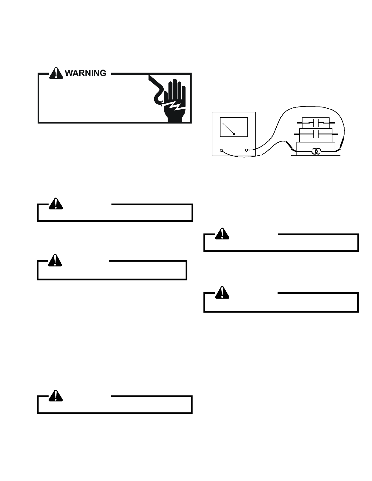
SERVICING
S-4 CHECKING TRANSFORMER AND CON-
TROL CIRCUIT
HIGH VOLT AGE!
Disconnect ALL power before servicing
or installing. Multiple power sources
may be present. Failure to do so may
cause property damage, personal injury
or death.
A step-down transformer (208/240 volt primary to 24 volt secondary) is provided with each indoor unit. This allows ample
capacity for use with resistance heaters. The outdoor sections do not contain a transformer (see note below).
TM
NOTE: ComfortNet
optional 240VAC to 24VAC transformer installed. This transformer provides 24VAC power to the unitary (UC) control in
some communicating system installation scenarios.
ready condensing units may have an
WARNING
Disconnect ALL power before servicing.
1. Remove control panel cover, or etc., to gain access to
transformer.
With power ON:
3. Using an ohmmeter, check for continuity across terminals 3 and 1, and 4 and 5.
4. Apply 24 volts to terminals H1 and H2. Check for
continuity across other terminals - should test continuous. If not as above - replace.
NOTE: The time delay for the contacts to make will be
approximately 20 to 50 seconds and to open after the coil is
de-energized is approximately 40 to 90 seconds.
OHMMETER
TESTING COIL CIRCUIT
S-8A CHECKING UNITARY (UC) CONTROL
COMPRESSOR CONTACTOR/RELAY
CONTACTS
WARNING
Disconnect ALL power before servicing.
WARNING
Line Voltage now present.
2. Using a voltmeter, check voltage across secondary voltage side of transformer (R to C).
3. No voltage indicates faulty transformer, bad wiring, or bad
splices.
4. Check transformer primary voltage at incoming line voltage connections and/or splices.
5 If line voltage available at primary voltage side of trans-
former and wiring and splices good, transformer is inoperative. Replace.
S-6 CHECKING TIME DELAY RELAY
Time delays are used in electric heaters to sequence in
multiple electric heaters.
WARNING
Disconnect ALL power before servicing.
1. Tag and disconnect all wires from male spade connections of relay.
2. Using an ohmmeter, measure the resistance across
terminals H1 and H2. Should read approximately 150
ohms.
1. Connect voltmeter to lugs (L2) and (C).
2. With power ON, provide a call for cool or heat pump to
energize the on-board compressor contactor/relay.
WARNING
Line Voltage now present.
3. Measure voltage across on-board compressor contactor/
relay contacts.
A. No voltage indicates the contacts are closed and the
contactor/relay is functioning properly.
B. A reading of approximately half of the supply voltage
(example: 115VAC for 230VAC) indicates the relay is
open. Replace UC control if relay does not close.
NOTE: The unitary (UC) control has a built-in short cycle
delay. Ensure short cycle delay has elapsed before making
voltage measurements.
49
Page 50

SERVICING
S-9 CHECKING HIGH AND LOW VOLTAGE TO
ECM MOTOR
HIGH VOLT AGE!
Disconnect ALL power before servicing
or installing. Multiple power sources
may be present. Failure to do so may
cause property damage, personal injury
or death.
1. Measure voltage between black and brown motor
leads. This should measure 208/230 volts depending
on your power supply.
2. If voltage is present proceed to check fan relay
contacts and voltage.
CHECKING FAN RELAY CONTACTS - ECM FAN MOTOR
1. Disconnect fan motor harness from plug on the UC
board.
2. Energize the system in low stage and check voltage:
• Pin 5(Blue wire) to Pin 3(Yellow wire) =
24VAC
3. Energize the system in high stage and check voltage:
• Pin 5(Blue wire) to Pin 3(Yellow wire) =
24VAC
• Pin 5(Blue wire) to Pin 1(White wire) = 24
VAC.
CHECKING RELAY CONTACTS - PSC FAN MOTOR
HIGH VOLT AGE!
Disconnect ALL power before servicing
or installing. Multiple power sources
may be present. Failure to do so may
cause property damage, personal injury
or death.
1. Disconnect the motor leads from 6-circuit fan motor wire
harness.
2. Connect a voltmeter between circuit 3 and circuits 2 (low
speed) or 1 (high speed).
NOTE: Circuit 3 is connected directly to L2.
3. Energize the system at low or high stage.
WARNING
Line V oltage now present.
4. The measured voltage between circuit 3 and circuits 2 or
1 should be approximately 0VAC, which indicates the
relay contacts are closed. A voltage measurement of
approximately 115VAC indicates the relay is open. Replace the control if the relay checks open when it should
be closed.
S-10A COPELAND COMFORT ALERTTM -
UNITARY (UC) CONTROL DIAGNOSTICS
Applies to ASXC, ASZC, and DSZC 2-stage models
4. If voltage is present at these pins plug harness into
plug on PC board and check voltages at motor to test
for broken wires.
5. If all voltages are present motor is defective and
needs to be replaced.
50
HIGH VOL TAGE!
Disconnect ALL power before servicing
or installing. Multiple power sources
may be present. Failure to do so may
cause pr ope rty dam age , pe rs onal inju ry
or death.
The Copeland Comfort AlertTM diagnostics are fully integrated
into the unitary (UC) control. The UC control and integraged
Comfort Alert™ diagnostics provide around-the-clock monitoring for common electrical problems, compressor defects
and broad system faults. If a problem is detected, LED
indicators flash the proper alert codes to help you quickly
pinpoint the problem.
The diagnostic tables on following pages provide detailed
information regarding the system symptons, indicators (LED
and thermostat), potential problem(s), and corrective actions. The diagnostic information applies to systems wired
as 24VAC traditional (legacy) systems and systems wired as
communicating systems with the CTK0* communicating
thermostat.
Page 51

SERVICING
to repair .
consecutive normal
• Tu rn po w er OFF prior
• Fault will clear after 30
PCBHR101-103
PBBGR101-102
cycles.
cycling 24VAC to
control.
• Faul t may be cleared by
replacement part(s).
• Replace w ith correct
to repair .
replacement part(s).
• Tu rn po w er OFF prior
• Replace w ith correct
to repair .
cycling 24VAC to
control.
• Tu rn po w er OFF prior
• M u st cl ear fault by
replacement part(s).
• Replace w ith correct
C o rrective Actions Notes & Cautions
Poss ible Cause s
ComfortNet™
Th ermostat Only
Fault
D escription
charge; adjust as
needed.
li qui d li ne;
repair/repl ace as
needed.
motor; repair/replace
• Veri f y re frige ran t
• C heck for rest ricte d
failu re.
• Restri c tion in liquid lin e.
01 • Low refrigerant charge.
FAU LT
• Low Side Fault. LOW SIDE
presen t;
extremely low.
• Indoor blo wer m ot o r
• Indoor t hermos tat set
call
OFF if no
as needed.
• Check indoor blow er
charge; adjust as
needed.
li qui d li ne;
repair/repl ace as
needed.
motor; repair/replace
th e r mo stat settin g.
• Veri f y re frige ran t
• Check indoor
• C heck for rest ricte d
failu re.
• L ow refrig eran t charge.
• Restri c tion in liquid lin e.
LPS OPEN 01
CO Trip.
• Low Pressure
presen t;
extremely low.
• Indoor blo wer m ot o r
• Indoor t hermos tat set
call
OFF if no
as needed.
switc h; re pai r / rep lace
• Check indoor blow er
as needed.
• Chec k low pressure
charge; adjust as
needed.
li qui d li ne;
repair/repl ace as
needed.
motor; repair/replace
th e r mo stat settin g.
• Veri f y re frige ran t
• Check indoor
• C heck for rest ricte d
failu re.
• L ow refrig eran t charge.
• Restri c tion in liquid lin e.
01
LPS
LOCKOU T
(3 Trips).
• LPC O Lock o ut
presen t;
extremely low.
• Indoor blo wer m ot o r
• Indoor t hermos tat set
call
OFF if no
as needed.
switc h; re pai r / rep lace
as needed.
• Check indoor blow er
• Chec k low pressure
th e r mo stat settin g.
• Check indoor
Dia gnostic/ Status LED Codes
OFF 1 Fl ash OFF ON if call
Green Yellow Red Red Y1 Mes sage Code
Symp toms of A bno rma l Oper ation
(Legacy & Com fo r tNet™ Th er mo s t at)
trips with average run time betw een
trips greater th an 3 ho urs.
and outdoor fan operating at low speed
dia gno s t ic/s t at us LED’s di splay the
• V e r y lon g run ti me.
• Four consecutive com pressor protect or
• Comp res sor operating at h igh speed
in dicated code.
• Integrated control module
ON 1 Flash O FF O N if call
dia gno s t ic/s t at us LED’s di splay the
• Compress or and outdoor fan are off.
in dicated code.
• Therm o stat demand is present.
• Integrated control module
O N 1 Flash ON ON if call
same thermostat demand.
dia gno s t ic/s t at us LED’s di splay the
in dicated code.
S ervice” icon ill um inated.
“Check Air Conditioner” or “Check
• Compress or and outdoor fan are off.
• Low pressure switch trip 3 times within
• Therm o stat demand is present.
• Integrated control module
• ComfortNet™ t hermos tat “Call for
H eat P ump ” m es sage.
• Comfo rtNet™ thermo stat scrolls
51
Page 52

SERVICING
to re pair .
cons e c ut ive nor m al
• Turn power OFF p ri or
cycles.
• Fault will clear after 4
PCBHR101-103
PBBGR101-102
cyc li ng 24 VAC to
control.
• Fault may be cleared by
r eplacement part(s).
• Replace with correct
to re pair .
r eplacement part(s).
• Turn power OFF p ri or
• Replace with correct
to re pair .
cyc li ng 24 VAC to
control.
• Turn power OFF p ri or
• Must clear fault by
r eplacement part(s).
• Replace with correct
to re pair .
cons e c ut ive nor m al
cycles.
cyc li ng 24 VAC to
control.
• Turn power OFF p ri or
• Fault will clear after 4
• Fault may be cleared by
r eplacement part(s).
• Replace with correct
Co rrective Act io ns Not es & Cautions
ComfortNet™
Fault
con denser coil.
m otor; repair/replace
as ne eded.
moto r wiring;
r epair/replace as
needed.
m otor capaci to r;
r eplace as neede d.
con denser coil.
m otor; repair/replace
as ne eded.
moto r wiring;
r epair/replace as
needed.
m otor capaci to r;
r eplace as neede d.
con denser coil.
m otor; repair/replace
as ne eded.
moto r wiring;
r epair/replace as
needed.
m otor capaci to r;
r eplace as neede d.
thermostat w irin g;
r epair/replace as
needed.
r elay operation;
r eplace control as
• Check and clean
• Check outdoor fan
• Check outdoor fan
Po ssible Causes
• O utdoor fan not running.
02 • Blocked condenser coil.
Thermostat Onl y
FAULT
Message Code
Description
• H igh Side Faul t HIGH SIDE
call
present;
OFF if no
• Check outdoor fan
• Check and clean
• Check outdoor fan
• Check outdoor fan
• Blo cked condenser coil.
• O utdoor fan not running.
HPS OP EN 02
CO Trip
• High Pressure
call
present;
OFF if no
• Check outdoor fan
• Check and clean
• Check outdoor fan
• Check outdoor fan
• O utdoor fan not running.
02 • Blocked condenser coil.
HPS
LOCKOUT
(3 Trips)
• HP CO Lo ckout
call
present;
OFF if no
• Check outdoor fan
• Check thermostat and
demand.
• Faulty compressor relay.
03 • Intermittent thermostat
CYCLE
• Short Cycling CMPR SHRT
call
present;
OFF if no
needed.
• Check compressor
52
OFF ON if call
Flashes
Diagnostic/Status LED Codes
OFF 2
Green Yellow Red Red Y1
Symptom s of Abnormal Operation
trips with average run time betw een
trips great er than 1 minute and less th an
15 minutes.
switc hes are closed.
diagnostic/ stat us LED’s display the
(Legacy & Comfort Net™ Thermostat)
• F ou r cons e c ut ive com pre s so r prot ec to r
• Lo w pressure and hi gh pressure
indicated co de.
• Integrated control module
OFF ON if call
Flashes
ON 2
diagnostic/ stat us LED’s display the
• Compressor and outdoor fan are off.
indicated co de.
• Thermostat d emand is present.
• Integrated control module
ON ON i f call
Flashes
ON 2
same thermostat demand.
diagnostic/ stat us LED’s display the
• Compressor and outdoor fan are off.
• Low pressure swi tch tri p 3 times within
indicated co de.
• Thermostat d emand is present.
• Integrated control module
OFF ON if call
Flashes
OFF 3
Service” icon il luminated.
“Check Air Co nditioner” or “Check
Heat Pump” message.
minut es each.
switc hes are closed.
diagnostic/ stat us LED’s display the
• ComfortNet™ thermostat “Call for
• C om f ort Net™ the r m os ta t sc r o lls
• Run ti me for last 4 cycles is less than 3
• Compressor pro tector has not tripped.
• Lo w pressure and hi gh pressure
indicated co de.
• Integrated control module
Page 53

SERVICING
to re pai r.
cyc li ng 24 VAC to
• Turn pow er OFF prior
con trol.
• Must clear fault by
PCBHR101-103
PBBGR101-102
to re pai r.
cyc li ng 24 VAC to
con trol.
r eplacemen t part(s).
• Replace with correct
to re pai r.
normal cycle.
cyc li ng 24 VAC to
con trol.
• Turn pow er OFF prior
• Fault will clear after 1
• Fau lt may be cleared by
r eplacemen t part(s).
• Replace with correct
to re pai r.
normal cycle.
cyc li ng 24 VAC to
con trol.
r eplacemen t part(s).
• Turn pow er OFF prior
• Turn pow er OFF prior
• Fault will clear after 1
• Fau lt may be cleared by
• Replace with correct
• Must clear fault by
r eplacemen t part(s).
• Replace with correct
Co rrective Actions Not es & Cautions
Po s sible Causes
ComfortNet™
Thermostat Onl y
Fault
operation;
repair/replace as
needed.
r eplace as needed.
repair/replace as
needed.
w ithin ra nge on rating
pl ate; contact local
u tility i s out of ran ge.
and fuses.
repair/replace as
needed.
repair/replace as
needed.
• Check compressor
04 • Compressor bearings are
Message Code
Description
• Lo cked Rot or LOCKED
• Check run capacitor;
• Check wiring;
• Verify li ne voltage is
wiring.
capacitor.
seized.
• F a i le d com pr e ss or r un
ROTOR
present;
OFF i f no
• L ow li ne volt age .
• Faulty run capacitor
call
• Check circuit brea kers
• C he ck wir i ng to un it;
• Check compressor;
w ir e d to c ontrol.
protector.
• Compressor not properly
• Fa iled compressor
05 • Power is disconnected.
CIRCUIT
• Open Circuit OPEN
call
present;
OFF i f no
wiring; repair/replace
• Check compressor
repair/replace as
needed.
r eplace as needed.
repair/replace as
as ne eded.
• Check compressor;
• Check run capacitor;
capacitor.
is open.
• F a i le d com pr e ss or r un
O PEN S TAR T 06 • Compressor start windi ng
Circuit
• Open Start
call
present;
OFF i f no
needed.
• Check wiring;
w ir e d to c ontrol.
wiring.
• Faulty compressor wiring.
• Compressor not properly
• Faulty run capacitor
repair/replace as
needed.
r eplace as needed.
repair/replace as
• Check compressor;
• Check run capacitor;
capacitor.
is open.
• F a i le d com pr e ss or r un
06 • Compressor start winding
LOCK
O PEN S TAR T
Circui t L ockout
• Open Start
call
present;
OFF i f no
needed.
• Check wiring;
w ir e d to c ontrol.
wiring.
• Faulty compressor wiring.
• Compressor not properly
• Faulty run capacitor
ON ON if call
Flashes
Diagno stic/ Status LED Codes
OFF 4
Green Yellow Red Red Y1
Symptoms of Abnormal Operation
(Legacy & Comfort Net™ Thermos tat)
consec ut ive ti m es .
than 15 seconds.
diagnostic/stat us LED’s display the
indicat ed code.
• C om pre s so r and ou tdo o r fan are off.
• Co m pressor protec tor trips fo ur
• Average run time between trips is less
• Integrated control module
Service” icon illu minated.
• ComfortNet™ thermostat “Call for
OFF ON if call
Flashes
OFF 5
“C he ck Air Co nd it io ner ” or “Che c k
Heat Pump” message.
gre a ter tha n 4 hour s.
switches are c lo sed .
diagnostic/stat us LED’s display the
indicat ed code.
• ComfortNet™ thermostat scrolls
• C om pre s so r and ou tdo o r fan are off fo r
• Lo w pressure and high press ure
• Integrated control module
Service” icon illu minated.
• ComfortNet™ thermostat “Call for
OFF ON if call
Flashes
OFF 6
“C he ck Air Co nd it io ner ” or “Che c k
Heat Pump” message.
switches are c lo sed .
diagnostic/stat us LED’s display the
indicat ed code.
• ComfortNet™ thermostat scrolls
• C om pre s so r and ou tdo o r fan are off.
• Lo w pressure and high press ure
• Integrated control module
Service” icon illu minated.
• ComfortNet™ thermostat “Call for
ON ON if call
Flashes
OFF 6
“Check Air Conditioner” or “Check
Heat Pump” message.
switches are c lo sed .
t imes with 5 minute de lay between eac h
det ection.
diagnostic/stat us LED’s display the
indicat ed code.
Service” icon illu minated.
“C he ck Air Co nd it io ner ” or “Che c k
• ComfortNet™ thermostat scrolls
• C om pre s so r and ou tdo o r fan are off.
• Lo w pressure and high press ure
• Open start circuit h as been detected 4
• Integrated control module
• ComfortNet™ thermostat “Call for
Heat Pump” message.
• ComfortNet™ thermostat scrolls
53
Page 54

SERVICING
to repair .
normal cy c le.
• Turn po wer OFF p rio r
• Fault will clear after 1
• Fault may be cleared by
PCBHR101-103
PBBGR101-102
to repair .
cycling 24V AC to
cont rol .
cycling 24V AC to
cont rol .
replacem ent part(s).
• Turn po wer OFF p rio r
• Replace with corr ect
• Mu st clear fault by
replacem ent part(s).
• Replace with corr ect
to repair .
voltage less than 185
• Turn po wer OFF p rio r
VAC.
• Control detects line
to repair .
voltage greater than 255
• Turn po wer OFF p rio r
VAC.
• Control detects line
Corrective Actions No tes & Cautions
Possible Causes
ComfortNet™
T hermo stat O n l y
Fault
repair/replace as
ne eded.
repair/replace as
• Check compressor;
open.
Messa ge Code
OPEN RUN 07 • Com pr ess or run w i ndi ng i s
Des cript ion
Circuit
• O pe n Run
present;
ne eded.
• Check wiring;
w i red t o cont rol.
• Com pr e s sor not pro pe r l y
• Faulty compress or wiring.
call
OFF if no
• Check compressor;
07 • Com pr ess or run w i ndi ng i s
OPEN RUN
• O pe n Run
repair/replace as
ne eded.
repair/replace as
ne eded.
• Check wiring;
open.
w i red t o cont rol.
• Com pr e s sor not pro pe r l y
• Faulty compress or wiring.
LOCK
Circuit Lockout
call
present;
OFF if no
and fuses.
conn e c ted to p ower
supply as specified on
rating plate.
volt age condition;
con ta c t loc a l ut ilit y if
ne eded.
volt age condition;
con ta c t loc a l ut ilit y if
ne eded.
conn e c ted to p ower
supply as specified on
rating plate.
volt age condition;
con ta c t loc a l ut ilit y if
• Verify unit is
08 • Low line voltage. • Check circuit breakers
VOLT
LOW LINE
Voltage
• Low Line
present;
OFF if no
• Correct lo w line
• Hig h line voltage. • C or r e c t hi gh line
08
HIGH LINE
• High Line
call
• Verify unit is
VOLT
Voltage
call
present;
OFF if no
ne eded.
• Correct lo w line
54
OFF ON if call
Fl ash es
Diagnostic/Status LED Codes
OFF 7
Green Yellow Red Red Y1
Symp tom s of Abnorm al Op era tion
(Legacy & ComfortNet™ Thermostat)
switches are closed.
diagnostic/status LED’s display the
indicated code.
• Compressor and outdoor fan are off.
• Low pressure and high pressure
• Integrated control module
Servic e ” i c o n il luminate d.
• ComfortNet™ therm ostat “Call for
ON ON if call
Fl ash es
OFF 7
“Check Air Con ditioner” or “Check
Heat Pump” message.
switches are closed.
times with 5 minute delay between each
detection.
diagnostic/status LED’s display the
indicated code.
• ComfortNet™ therm ostat scrolls
• Compressor and outdoor fan are off.
• Low pressure and high pressure
• Open run circuit has been detected 4
• Integrated control module
Servic e ” i c o n il luminate d.
• ComfortNet™ therm ostat “Call for
OFF ON if call
Fl ash es
OFF 8
“Check Air Con ditioner” or “Check
Heat Pump” message.
to be operating normally.
(c ompress or a nd ou tdo or fa n off).
diagnostic/status LED’s display the
• ComfortNet™ therm ostat scrolls
• Air cond itioner/heat pump may appear
• Compressor protector may be o pen
indicated code.
• Integrated control module
OFF ON if call
Fl ash es
ON 8
to be operating normally.
• Air cond itioner/heat pump may appear
• Compressor protector may be o pen
(compre ss or a nd outdoor fan off).
diagnostic/status LED’s display the
indicated code.
• Integrated control module
Page 55

SERVICING
to rep air .
• Turn power O F F p rior
• Fault will clear if
PCBHR101-103
PBBGR101-102
second ary voltag e rises
above 2 1V AC .
rep la cement par t(s ).
to rep air .
normal cy cle.
cycling 24V AC t o
con tro l.
• Replace with co rrect
• Turn power O F F p rior
• Fault will clear af ter 1
• Fault may be cleared by
rep la cement par t(s ).
• Replace with co rrect
Corrective Actions Notes & Ca uti ons
Possible Causes
ComfortNet™
T herm o stat Only
Message Code
Fa ul t
D escription
voltage conditio n .
• Transformer o verloaded.
VOLT
OFF i f no
replace if nee ded.
• Check transformer;
• Low l ine voltage.
call
• Check f use.
• Corr ect low se condary
vo ltage less than 18 V AC.
09 • Control detects secondary
LO W
SECOND
Voltage
• Low Pi lot
present;
repair/ replace as
needed.
repair/ replace as
needed.
• Check compressor;
• Check wiring;
start win dings .
• No current through run or
Not
Not di splayed
• Comp Protector
is ope n.
• Compressor run w inding
• Compress or not pr ope rly
displ ayed
Open
call
present;
OFF i f no
replace as needed.
• Check run capacitor;
w ired t o control.
capacitor.
• Faulty compressor wiring.
• F ailed com p ressor run
wiring.
• Faulty run capacitor
OFF ON if call
Fl ashes
Diagnost ic/Status LED Codes
OFF 9
G reen Yell ow Red Red Y 1
Sym pto m s of Abn ormal O p eration
(Legacy & ComfortN et™ Thermostat)
to be opera ting normally.
diagnostic/status LED ’s dis play the
• Air conditioner/heat pum p m ay appear
i ndicated code.
• Integ rated control m odule
OFF ON ON ON if call
• Com pres so r i s off .
• Integ rated control m odule
diagnostic/status LED ’s dis play the
i ndicated code.
55
Page 56

SERVICING
PCBHR104/PCBHR105
7 SEGMENT LED
(DS2)
0 n Standby
0 1 Low Pressure CO Trip
0 1 Low Side Fault
0 2 High Pressure CO Trip
0 2 High Side Fault
0 3 Short Cycling
0 4 Locked Rotor
0 5 Open Circuit
0 6 Open Start Circuit
0 7 Open Run Circuit
0 8 No Line Voltage
0 9 Low Pilot Voltage
88 Power Up
A 2 Outdoor Air Temp Sensor Fault
A 3 Outdoor Coil Tem p Sensor Fault *
b 0 No Indoor Airflow
b 9 Inadequate Airflow
C 3 Cool Mode Short Cycle Timer
C 1 Low Cool
C 2 High Cool
dF Defrost *
d t Max Defrost Time *
d E Forced Defrost *
d 0 Data not yet on N e twork
d 1 Invalid Data on Netw ork
d 2 System Mis-Match
d 3 Configuration Mis-Match
d 4 Invalid Memory Card Data
E E Board Misoperation
E 5 Open Fuse
F t Fiel d Test Mode
H 8 High Line Voltage
L 1 LPCO Lockout (3 Trips)
L 2 HPCO Lockout (3 Trips)
L 6 Open Start Circuit Lockout
L 7 Open Run Circuit Lockout
L 8 Low Line Voltage
P 3 Heat Mode Short Cycle Timer *
P 1 Low Heat *
P 2 High Heat *
P 0 Comp Protector Open
Pd Pump Down
7 S EGME NT LE D
(DS1)
DE SCRIPTION O F COND ITIO N
56
* CODE USED ON HEAT P UM P MODELS ONLY
NOTE 1: DS1, DS2 AND DS3 ARE LABELED ON THE CONTROL ABOVE EACH 7
SEGMENT LED DISPLAY
NOTE 2: 7 SEGMENT LED DISPLAY DS3 IS NOT USED
0140M00407-A
Page 57
SERVICING
3YMPTOMSOF
!BNORMAL/PERATION
,EGACY#OMFORT.ET
4HERMOSTAT
sIntegrated control
module diagnostic/status
LED display shows the
indicated code.
s#OMFORT.ETTHERMOSTAT
displays ‘---‘ in the
temperature display area.
sHeat pump fails to operate
in heating mode.
sIntegrated control
module diagnostic/status
LED display shows the
indicated code.
s#OMFORT.ETTHERMOSTAT
displays error message.
sAir conditioner/heat pump
fails to operate.
sIntegrated control
module diagnostic/status
LED display shows the
indicated code.
sAir conditioner/heat pump
fails to operate.
sIntegrated control
module diagnostic/status
LED display shows the
indicated code.
sAir conditioner/heat pump
fails to operate.
sIntegrated control
module diagnostic/status
LED display shows the
indicated code.
s#OMFORT.ETTHERMOSTAT
displays error message.
s Air conditioner/heat
pump operates at reduced
performance.
sAir conditioner/heat pump
operating at low stage
when expected to operate
at high stage.
sIntegrated control
module diagnostic/status
LED display shows the
indicated code.
3934%-42/5",%3(//4).'
5.)4!29$)!'./34)##/$%3
$IAGNOSTIC3TATUS
,%$$ISPLAY#ODES
$IGIT $IGIT $IGIT -ESSAGE #ODE
",!.+ A 2 sOutdoor air
",!.+ A3s Outdoor coil
",!.+ E5s Open fuse ",/7.
",!.+ EEs Board mis-
",!.+ b0s Circulator
",!.+ b9s Airflow is
&AULT
$ESCRIPTION
temp sensor
fault
temp sensor
fault
operation
blower motor
is not running
when it
should be
running.
lower than
demanded
#OMFORT.ET
4HERMOSTAT/NLY
AIR
3%.3/2
FLT
COIL
3%.3/2
FLT
FUSE
).4%2.!,
FAULT
MOTOR
./425.
LOW ID
AIRFLOW
4-
A2 s Shorted sensor.
A3 sShorted sensor
E5 s Short in low
EE sCompressor
b0 sIndoor blower
b9 sIndoor blower
0OSSIBLE
#AUSES
sOpen sensor.
sSensor
disconnected.
sSensor out of
range.
sOpen sensor.
sSensor.
disconnected.
sSensor out of
range.
voltage wiring.
relay contacts
welded.
motor problem.
sCommunications
error between
indoor and
outdoor unit.
motor problem
s
Blocked filters.
sRestrictive/
undersized
ductwork
sIndoor/ outdoor
unit miss-match.
PCBHR104
#ORRECTIVE
!CTIONS
sCheck sensor
connection.
sReplace open/
shorted sensor.
sCheck sensor
connection.
sReplace open/
shorted sensor.
sLocate and
correct short
in low voltage
wiring.
sReplace control. sTurn power OFF prior
sCheck indoor
blower motor.
sCheck indoor
blower motor
wiring.
sCheck indoor unit
control.
sRepair/ replace
any faulty wiring.
sRepair/ replace
indoor blower
motor or control.
sCheck indoor
blower motor.
sCheck filters;
clean/replace as
needed.
sCheck ductwork;
resize as needed.
sVerify indoor and
outdoor units are
properly matched.
.OTES
#AUTIONS
sTurn power OFF prior
to repair.
sReplace with correct
replacement part.
sTurn power OFF prior
to repair.
sReplace with correct
replacement part.
sTurn power OFF prior
to repair.
sReplace fuse with
3-amp automotive type.
to repair
sReplace with correct
replacement part.
sTurn power OFF prior
to repair.
sApplies only to fully
communicating system
USING#OMFORT.ET
thermostat.
sReplace with correct
replacement part.
sTurn power OFF prior
to repair.
sApplies only to fully
communicating system
USING#OMFORT.ET
thermostat.
sReplace with correct
replacement part. See
specification sheet(s)
for airflow requirements
and maximum external
static pressure.
sSee specification
sheets for approved
system matches.
57
Page 58
SERVICING
3YMPTOMSOF
!BNORMAL/PERATION
,EGACY#OMFORT.ET
4HERMOSTAT
sAir conditioner/heat pump
fails to operate.
sIntegrated control
module diagnostic/status
LED display shows the
indicated code.
s#OMFORT.ETTHERMOSTAT
displays error message.
sAir conditioner/heat pump
fails to operate.
sIntegrated control
module diagnostic/status
LED display shows the
indicated code.
s#OMFORT.ETTHERMOSTAT
displays error message.
sAir conditioner/heat pump
fails to operate.
sAir conditioner/heat pump
operating at reduced
performance.
sAir conditioner/heat pump
operating at low stage
when expected to operate
at high stage.
sIntegrated control
module diagnostic/status
LED display shows the
indicated code.
s#OMFORT.ETTHERMOSTAT
displays error message.
5.)4!29$)!'./34)##/$%3
$IAGNOSTIC3TATUS
,%$$ISPLAY#ODES &AULT
$IGIT $IGIT $IGIT -ESSAGE #ODE
",!.+ d0sData not yet
",!.+ d1sInvalid Data
",!.+ d2s System
$ESCRIPTION
ON.ETWORK
ON.ETWORK
Mis-Match
#OMFORT.ET4-
4HERMOSTAT/NLY 0OSSIBLE
./.%4
DATA
).6!,)$
DATA
).6!,)$
SYSTEM
d0 sAir conditioner/
d1 s Air conditioner/
d2 sAir conditioner/
#AUSES
heat pump is
wired as part of
a communicating
system and
integrated control
module does
not contain any
shared data.
heat pump is
wired as part of
a communicating
system and
integrated control
module contains
invalid shared
data or network
data is invalid for
the integrated
control module.
heat pump is
wired as part of
a communicating
system and
outdoor unit
requires airflow
greater than
indoor unit’s
airflow capability.
sShared data is
incompatible
with the system
or missing
parameters.
#ORRECTIVE
!CTIONS
sVerify
system type
(communicating
or legacy)
sPopulate shared
data using
memory card
sWire system as
legacy system
sVerify
system type
(communicating
or legacy).
sPopulate correct
shared data using
memory card.
sWire system as
legacy system.
sVerify system type
(communicating
or legacy).
sVerify shared
data is correct
for your specific
model; repopulate data if
required.
sWire system as
legacy system.
PCBHR104
.OTES
#AUTIONS
sTurn power OFF prior
to repair.
sUse memory card for
your specific model.
sInsert memory card
BEFORE turning power
/.-EMORYCARDMAY
be removed after data
is loaded. Turn power
OFF before removing
memory card.
sError code will
be cleared once
data is loaded.
Applies only to fully
communicating system
USING#OMFORT.ET
thermostat.
58
Page 59

SERVICING
5.)4!29$)!'./34)##/$%3
3YMPTOMSOF
!BNORMAL/PERATION
,EGACY#OMFORT.ET
4HERMOSTAT
$IAGNOSTIC3TATUS
,%$$ISPLAY#ODES &AULT
$ESCRIPTION
#OMFORT.ET4-
4HERMOSTAT/NLY 0OSSIBLE
#AUSES
#ORRECTIVE
!CTIONS
.OTES
#AUTIONS
$IGIT $IGIT $IGIT -ESSAGE #ODE
s Air conditioner/heat pump
fails to operate.
sIntegrated control module
diagnostic/status LED
display shows the indicated
code.
s#OMFORT.ETTHERMOSTAT
displays error message.
",!.+ d3s Configuration
Mis-match
).6!,)$
#/.&)'
d3 sShared data sent
to integrated
control module
does not match
hardware
configuration.
sVerify
system type
(communicating
or legacy).
sVerify shared
data is correct
for your specific
model; repopulate data if
required.
sWire system as
legacy system.
sTurn power OFF prior
to repair.
sUse memory card for
your specific model.
sInsert memory card
BEFORE turning power
/.-EMORYCARDMAY
be removed after data
is loaded. Turn power
OFF before removing
memory card.
sError code will
be cleared once
data is loaded.
Applies only to fully
communicating system
USING#OMFORT.ET
thermostat.
sAir conditioner/heat pump
fails to operate.
sIntegrated control
module diagnostic/status
LED display shows the
indicated code.
s#OMFORT.ETTHERMOSTAT
displays error message.
",!.+ d4s Invalid
Memory
Card Data
).6!,)$
MC DATA
d4 sShared data on
memory card has
been rejected.
sVerify
system type
(communicating
or legacy).
sVerify shared
data is correct
for your specific
model; repopulate data if
required.
sWire system as
legacy system.
sTurn power OFF prior
to repair.
sUse memory card for
your specific model.
sInsert memory card
BEFORE turning power
/.-EMORYCARDMAY
be removed after data
is loaded. Turn power
OFF before removing
memory card.
sError code will be
cleared once data is
loaded.
s Very long run time.
sFour consecutive
compressor protector
trips with average run
time between trips greater
than 3 hours.
sCompressor operating at
high speed and outdoor fan
operating at low speed
sIntegrated control
module diagnostic/status
LED display shows the
indicated code.
",!.+ 01s Low Side
Fault
LOW SIDE
FAULT
01 s Low refrigerant
charge.
sRestriction in
liquid line.
sIndoor blower
motor failure.
sIndoor
thermostat set
extremely low.
sVerify refrigerant
charge; adjust as
needed.
sCheck for
restricted liquid
line; repair/
replace as
needed.
sCheck indoor
blower motor;
repair/replace as
needed.
sCheck indoor
thermostat setting.
sTurn power OFF prior
to repair.
sFault will clear after 30
consecutive normal
cycles.
sFault may be cleared
by cycling 24VAC to
control.
sReplace with correct
replacement part(s).
sCompressor and outdoor
fan are off.
sThermostat demand is
present.
sIntegrated control
module diagnostic/status
LED display shows the
indicated code.
",!.+ 01s Low Pressure
Cut Out Trip
,03/0%. 01 s Low refrigerant
charge.
sRestriction in
liquid line.
sIndoor blower
motor failure.
sIndoor
thermostat set
extremely low.
sVerify refrigerant
charge; adjust as
needed.
sCheck for
restricted liquid
line; repair/
replace as
needed.
sCheck indoor
blower motor;
repair/replace as
needed.
sCheck low
pressure switch;
repair/replace as
needed.
sCheck indoor
thermostat setting.
sTurn power OFF prior
to repair.
sReplace with correct
replacement part(s).
PCBHR104
59
Page 60

SERVICING
Compressor and outdoor
f
Low pressure switch
trip 3 times within same
thermostat demand.
Thermostat demand is
present.
Integrated control
module diagnostic/status
LED display shows the
indicated code.
displays error message.
Four consecutive
compressor protector trips
with average run time
between trips greater than
1 minute and less than 15
minutes.
Low pressure and high
pressure switches are
closed.
Integrated control
module diagnostic/status
LED display shows the
indicated code.
Compressor and outdoor
f
Thermostat demand is
present.
Integrated control
module diagnostic/status
LED display shows the
indicated code.
Compressor and outdoor
f
Low pressure switch
trip 3 times within same
thermostat demand.
Thermostat demand is
present.
Integrated control
module diagnostic/status
LED display shows the
indicated code.
displays error message.
.
.
.
Digit 3 Digit 2 Digit 1
L1Low Pressure
02High Side
02High
L2High
Cut Out
Lockout
(3 T rips)
Fault
Pressure
Cut Out
Trip
Pressure
Cut Out
Lockout
(3 T rips)
LPS 01 Low refrigerant
HIGH SIDE
FAULT
HPS 02 Blocked
charge.
Restriction in
liquid line.
Indoor blower
motor failure.
Indoor
thermostat set
extremely low.
02 Blocked
condenser coil.
Outdoor fan not
running.
02 Blocked
condenser coil.
Outdoor fan not
running.
condenser coil.
Outdoor fan not
running.
Verify refrigerant
charge; adjust as
needed.
Check for
restricted liquid
line; repair/replace
as needed.
Check indoor
blower motor;
repair/replace as
needed.
Check low
pressure switch;
repair/replace as
needed.
Check indoor
thermostat setting.
Check and clean
condenser coil.
Check outdoor
fan motor; repair/
replace as
needed.
Check outdoor
fan motor wiring;
repair/replace as
needed.
Check outdoor
fan motor
capacitor; replace
as needed.
Check and clean
condenser coil.
Check outdoor
fan motor; repair/
replace as
needed.
Check outdoor
fan motor wiring;
repair/replace as
needed.
Check outdoor
fan motor
capacitor; replace
as needed.
Check and clean
condenser coil.
Check outdoor
fan motor; repair/
replace as
needed.
Check outdoor
fan motor wiring;
repair/replace as
needed.
Check outdoor
fan motor
capacitor; replace
as needed.
PCBHR104
Turn power OFF prior
to repair.
Must clear fault by
cycling 24VAC to
control.
Replace with correct
replacement part(s).
Turn power OFF prior
to repair.
Fault will clear after 4
consecutive normal
cycles.
Fault may be cleared
by cycling 24VAC to
control.
Replace with correct
replacement part(s).
Turn power OFF prior
to repair.
Replace with correct
replacement part(s).
Turn power OFF prior
to repair.
Must clear fault by
cycling 24VAC to
control.
Replace with correct
replacement part(s).
60
Page 61

SERVICING
1
PCBHR104
Digit 3 Digit 1Digit 2
Run time for last 4 cycles
is less than 3 minutes
each.
Compressor protector has
not tripped.
Low pressure and high
pressure switches are
closed.
Integrated control
module diagnostic/status
LED display shows the
indicated code.
Compressor and outdoor
f
Compressor protector trips
four consecutive times.
Average run time between
trips is less than 15
seconds.
Integrated control
module diagnostic/status
LED display shows the
indicated code.
displays error message.
Compressor and outdoor
f
4 hours.
Low pressure and high
pressure switches are
closed.
Integrated control
module diagnostic/status
LED display shows the
indicated code.
displays error message.
Compressor and outdoor
f
Low pressure and high
pressure switches are
closed.
Integrated control
module diagnostic/status
LED display shows the
indicated code.
displays error message.
.
or greater than
.
03Short Cycling CMPR
04Locked Rotor
05Open Circuit
06Open Start
Circuit
SHRT
CYCLE
ROTOR
CIRCUIT
START
03 Intermittent
thermostat
demand.
Faulty
compressor
relay.
Compressor
04
bearings are
seized.
Failed
compressor run
capacitor.
Faulty run
capacitor wiring.
Low line voltage.
05
Power is
disconnected.
Failed
compressor
protector.
Compressor not
properly wired to
control.
06
Compressor start
winding is open.
Failed
compressor run
capacitor.
Faulty run
capacitor wiring.
Compressor not
properly wired to
control.
Faulty
compressor
wiring.
Check thermostat
and thermostat
wiring; repair/
replace as
needed.
Check
compressor
relay operation;
replace control as
needed.
Check
compressor
operation; repair/
replace as
needed.
Check run
capacitor; replace
as needed.
Check wiring;
repair/replace as
needed.
Verify line voltage
is within range
on rating plate;
contact local
utility is out of
range.
Check circuit
breakers and
fuses.
Check wiring
to unit; repair/
replace as
needed.
Check
compressor;
repair/replace as
needed
Check
compressor
wiring; repair/
replace as
needed.
Check
compressor;
repair/replace as
needed.
Check run
capacitor; replace
as needed.
Check wiring;
repair/replace as
needed.
Turn power OFF prior
to repair.
Fault will clear after 4
consecutive normal
cycles.
Fault may be cleared
by cycling 24VAC to
control.
Replace with correct
replacement part(s).
Minimum compressor
runt time is changed
from 30 seconds to 3
minutes.
Turn power OFF prior
to repair.
Must clear fault by
cycling 24VAC to
control.
Replace with correct
replacement part(s).
Turn power OFF prior
to repair.
Fault will clear after
normal cycle.
Fault may be cleared
by cycling 24VAC to
control.
Replace with correct
replacement part(s).
Turn power OFF prior
to repair.
Fault will clear after 1
normal cycle.
Fault may be cleared
by cycling 24VAC to
control.
Replace will correct
replacement part(s).
61
Page 62

SERVICING
PCBHR104
Digit 3 Digit 2 Digit 1
Compressor and outdoor
f
Low pressure and high
pressure switches are
closed.
Open start circuit has been
detected 4 times with 5
minute delay between each
detection.
Integrated control
module diagnostic/status
LED display shows the
indicated code.
displays error message.
Compressor and outdoor
f
Low pressure and high
pressure switches are
closed.
Integrated control
module diagnostic/status
LED display shows the
indicated code.
displays error message.
.
.
Compressor and outdoor
f
Low pressure and high
pressure switches are
closed.
Open run circuit has been
detected 4 times with 5
minute delay between
each detection.
Integrated control
module diagnostic/status
LED display shows the
indicated code.
displays error message.
Air conditioner/heat
pump may appear to be
operating normally.
Compressor protector may
be open (compressor and
outdoor f
Integrated control
module diagnostic/status
LED display shows the
indicated code.
.
L6Open Start
Circuit
Lockout
07Open Run
Circuit
L7Open Run
Circuit
Lockout
L8Low Line
Voltage
START
VOLT
06 Compressor start
winding is open.
Failed
compressor run
capacitor.
Faulty run
capacitor wiring.
Compressor not
properly wired
to control.
Faulty
compressor
wiring.
07 Compressor run
winding is open.
Compressor not
properly wired
to control.
Faulty
compressor
wiring.
07 Compressor run
winding is open.
Compressor not
properly wired
to control.
Faulty
compressor
wiring.
Low line voltage. Check circuit
08
Check
compressor;
repair/replace as
needed.
Check run
capacitor; replace
as needed.
Check wiring
repair/replaced
as needed.
Check
compressor;
repair/replace as
needed.
Check wiring;
repair/replace as
needed.
Check compressor; repair/replace as needed.
Check wiring;
repair/replace as
needed.
breakers and
fuses.
Verify unit is
connected to
power supply
rating plate.
Correct low line
voltage condition;
contact local
utility if needed.
Turn power OFF prior
to repair
Must clear fault by
cycling 24VAC to
control.
Replace with correct
replacement part(s).
Turn power OFF prior
to repair.
Fault will clear after 1
normal cycle.
Fault may be cycling
24VAC to control.
Replace with correct
replacement part(s).
Turn power OFF prior
to repair.
Must clear fault by cycling 24VAC to control.
Replace with correct
replacement part(s).
Turn power OFF prior
to repair.
Control detects line
voltage less than
185 VA C.
Fault will clear if line
voltage increases
above 185 VAC.
62
Page 63

SERVICING
PCBHR104
Air conditioner/heat
pump may appear to be
operating normally.
Compressor protector
may be open (compressor
and outdoor f
Integrated control
module diagnostic/status
LED display shows the
indicated code.
Air conditioner/heat
pump may appear to be
operating normally.
Integrated control
module diagnostic/status
LED display shows the
indicated code.
Integrated control
module diagnostic/status
LED display shows the
indicated code.
Air conditioner/heat
pump may appear to be
operating normally.
Compressor protector
may be open (compressor
and outdoor f
Integrated control
module diagnostic/status
LED display shows the
indicated code.
.
Digit 3
Digit 1Digit 2
H8High Line
Voltage
09Low Pilot
Voltage
P0Comp
Protector
Open
08
08
VOLT
LOW
VOLT
displayed displayed through run or
VOLT AGE
High line
voltage
Control detects
09
secondary
voltage less
than 18 VAC.
Transformer
overloaded.
Low line voltage.
start windings.
Compressor
run winding is
open.
Compressor not
properly wired to
control.
Faulty
compressor
wiring.
Failed
compressor run
capacitor.
Faulty run
capacitor wiring.
08 Check circuit
Correct high line
voltage condition;
contact local utility
if needed.
Verify unit is
connected to power
on rating plate.
Check fuse.
Correct low secondary voltage condition.
Check transformer;
replace if needed.
Check compressor;
repair/replace as
needed.
Check wiring; repair/
replace as needed.
Check run capacitor; replace as
needed.
breaker and fuses.
Verify unit is connected to power
on rating plate.
Turn power OFF prior
to repair.
Control detects line
voltage greater than
255 VA C.
Fault will clear if line
voltage decreases
below 255 VAC.
T urn power OFF prior to
repair.
Fault will clear if
secondary voltage rises
above 21V AC.
Replace with correct
replacement part(s).
Turn power OFF prior
to repair.
Fault will clear after 1
normal cycle.
Fault may be cleared
by cycling 24VAC to
control.
Replace with correct
replacement part(s).
Turn power OFF prior
to repair.
Control detects line
voltage less than
185 VA C.
Fault will clear if line
voltage increases
above 185 VAC.
63
Page 64

SERVICING
3YMPTOMSOF
!BNORMAL/PERATION
,EGACY#OMFORT.ET
4HERMOSTAT
sIntegrated control
module diagnostic/status
LED display shows the
indicated code.
s#OMFORT.ETTHERMOSTAT
displays ‘---‘ in the
temperature display area.
sHeat pump fails to operate
in heating mode.
sIntegrated control
module diagnostic/status
LED display shows the
indicated code.
s#OMFORT.ETTHERMOSTAT
displays error message.
sAir conditioner/heat pump
fails to operate.
sIntegrated control
module diagnostic/status
LED display shows the
indicated code.
sAir conditioner/heat pump
fails to operate.
sIntegrated control
module diagnostic/status
LED display shows the
indicated code.
sAir conditioner/heat pump
fails to operate.
sIntegrated control
module diagnostic/status
LED display shows the
indicated code.
s#OMFORT.ETTHERMOSTAT
displays error message.
s Air conditioner/heat
pump operates at reduced
performance.
sAir conditioner/heat pump
operating at low stage
when expected to operate
at high stage.
sIntegrated control
module diagnostic/status
LED display shows the
indicated code.
3934%-42/5",%3(//4).'
5.)4!29$)!'./34)##/$%3
$IAGNOSTIC3TATUS
,%$$ISPLAY#ODES
$IGIT $IGIT $IGIT -ESSAGE #ODE
",!.+ A 2 sOutdoor air
",!.+ A3s Outdoor coil
",!.+ E5s Open fuse ",/7.
",!.+ EEs Board mis-
",!.+ b0s Circulator
",!.+ b9s Airflow is
&AULT
$ESCRIPTION
temp sensor
fault
temp sensor
fault
operation
blower motor
is not running
when it
should be
running.
lower than
demanded
#OMFORT.ET
4HERMOSTAT/NLY
AIR
3%.3/2
FLT
COIL
3%.3/2
FLT
FUSE
).4%2.!,
FAULT
MOTOR
./425.
LOW ID
AIRFLOW
4-
A2 s Shorted sensor.
A3 s Shorted sensor
E5 s Short in low
EE sCompressor
b0 sIndoor blower
b9 sIndoor blower
0OSSIBLE
#AUSES
sOpen sensor.
sSensor
disconnected.
sSensor out of
range.
sOpen sensor.
sSensor.
disconnected.
sSensor out of
range.
voltage wiring.
relay contacts
welded.
motor problem.
sCommunications
error between
indoor and
outdoor unit.
motor problem
s
Blocked filters.
sRestrictive/
undersized
ductwork
sIndoor/ outdoor
unit miss-match.
PCBHR105
#ORRECTIVE
!CTIONS
sCheck sensor
connection.
sReplace open/
shorted sensor.
sCheck sensor
connection.
sReplace open/
shorted sensor.
sLocate and
correct short
in low voltage
wiring.
sReplace control. sTurn power OFF prior
sCheck indoor
blower motor.
sCheck indoor
blower motor
wiring.
sCheck indoor unit
control.
sRepair/ replace
any faulty wiring.
sRepair/ replace
indoor blower
motor or control.
sCheck indoor
blower motor.
sCheck filters;
clean/replace as
needed.
sCheck ductwork;
resize as needed.
sVerify indoor and
outdoor units are
properly matched.
.OTES
#AUTIONS
sTurn power OFF prior
to repair.
sReplace with correct
replacement part.
sTurn power OFF prior
to repair.
sReplace with correct
replacement part.
sTurn power OFF prior
to repair.
sReplace fuse with
3-amp automotive type.
to repair
sReplace with correct
replacement part.
sTurn power OFF prior
to repair.
sApplies only to fully
communicating system
USING#OMFORT.ET
thermostat.
sReplace with correct
replacement part.
sTurn power OFF prior
to repair.
sApplies only to fully
communicating system
USING#OMFORT.ET
thermostat.
sReplace with correct
replacement part. See
specification sheet(s)
for airflow requirements
and maximum external
static pressure.
sSee specification
sheets for approved
system matches.
64
Page 65

SERVICING
5.)4!29$)!'./34)##/$%3
3YMPTOMSOF
!BNORMAL/PERATION
,EGACY#OMFORT.ET
4HERMOSTAT
$IAGNOSTIC3TATUS
,%$$ISPLAY#ODES &AULT
$ESCRIPTION
#OMFORT.ET4-
4HERMOSTAT/NLY 0OSSIBLE
#AUSES
#ORRECTIVE
!CTIONS
.OTES
#AUTIONS
$IGIT $IGIT $IGIT -ESSAGE #ODE
sAir conditioner/heat pump
fails to operate.
sIntegrated control
module diagnostic/status
LED display shows the
indicated code.
s#OMFORT.ETTHERMOSTAT
displays error message.
",!.+ d0sData not yet
ON.ETWORK
./.%4
DATA
d0 sAir conditioner/
heat pump is
wired as part of
a communicating
system and
integrated control
module does
not contain any
shared data.
sVerify
system type
(communicating
or legacy)
sPopulate shared
data using
memory card
sWire system as
legacy system
sTurn power OFF prior
to repair.
sUse memory card for
your specific model.
sInsert memory card
BEFORE turning power
/.-EMORYCARDMAY
be removed after data
is loaded. Turn power
OFF before removing
memory card.
sError code will
be cleared once
data is loaded.
Applies only to fully
communicating system
USING#OMFORT.ET
thermostat.
sAir conditioner/heat pump
fails to operate.
sIntegrated control
module diagnostic/status
LED display shows the
indicated code.
s#OMFORT.ETTHERMOSTAT
displays error message.
",!.+ d1sInvalid Data
ON.ETWORK
).6!,)$
DATA
d1 s Air conditioner/
heat pump is
wired as part of
a communicating
system and
integrated control
module contains
invalid shared
data or network
data is invalid for
the integrated
control module.
sVerify
system type
(communicating
or legacy).
sPopulate correct
shared data using
memory card.
sWire system as
legacy system.
sTurn power OFF prior
to repair.
sUse memory card for
your specific model.
sInsert memory card
BEFORE turning power
/.-EMORYCARDMAY
be removed after data
is loaded. Turn power
OFF before removing
memory card.
sError code will
be cleared once
data is loaded.
Applies only to fully
communicating system
USING#OMFORT.ET
thermostat.
sAir conditioner/heat pump
fails to operate.
sAir conditioner/heat pump
operating at reduced
performance.
sAir conditioner/heat pump
operating at low stage
when expected to operate
at high stage.
sIntegrated control
module diagnostic/status
LED display shows the
indicated code.
s#OMFORT.ETTHERMOSTAT
displays error message.
",!.+ d2s System
Mis-Match
).6!,)$
SYSTEM
d2 sAir conditioner/
heat pump is
wired as part of
a communicating
system and
outdoor unit
requires airflow
greater than
indoor unit’s
airflow capability.
sShared data is
incompatible
with the system
or missing
parameters.
sVerify system type
(communicating
or legacy).
sVerify shared
data is correct
for your specific
model; repopulate data if
required.
sWire system as
legacy system.
sTurn power OFF prior
to repair.
sUse memory card for
your specific model.
sInsert memory card
BEFORE turning power
/.-EMORYCARDMAY
be removed after data
is loaded. Turn power
OFF before removing
memory card.
sError code will
be cleared once
data is loaded.
Applies only to fully
communicating system
USING#OMFORT.ET
thermostat.
PCBHR105
65
Page 66

SERVICING
3YMPTOMSOF
!BNORMAL/PERATION
,EGACY#OMFORT.ET
4HERMOSTAT
s Air conditioner/heat pump
fails to operate.
sIntegrated control module
diagnostic/status LED
display shows the indicated
code.
s#OMFORT.ETTHERMOSTAT
displays error message.
sAir conditioner/heat pump
fails to operate.
sIntegrated control
module diagnostic/status
LED display shows the
indicated code.
s#OMFORT.ETTHERMOSTAT
displays error message.
s Very long run time.
sFour consecutive
compressor protector
trips with average run
time between trips greater
than 3 hours.
sCompressor operating at
high speed and outdoor fan
operating at low speed
sIntegrated control
module diagnostic/status
LED display shows the
indicated code.
sCompressor and outdoor
fan are off.
sThermostat demand is
present.
sIntegrated control
module diagnostic/status
LED display shows the
indicated code.
5.)4!29$)!'./34)##/$%3
$IAGNOSTIC3TATUS
,%$$ISPLAY#ODES &AULT
$IGIT $IGIT $IGIT -ESSAGE #ODE
",!.+ d3s Configuration
",!.+ d4s Invalid
",!.+ 01s Low Side
",!.+ 01s Low Pressure
$ESCRIPTION
Mis-match
Memory
Card Data
Fault
Cut Out Trip
#OMFORT.ET4-
4HERMOSTAT/NLY 0OSSIBLE
).6!,)$
#/.&)'
).6!,)$
MC DATA
LOW SIDE
FAULT
,03/0%. 01 s Low refrigerant
d3 sShared data sent
d4 sShared data on
01 s Low refrigerant
#AUSES
to integrated
control module
does not match
hardware
configuration.
memory card has
been rejected.
charge.
sRestriction in
liquid line.
sIndoor blower
motor failure.
sIndoor
thermostat set
extremely low.
charge.
sRestriction in
liquid line.
sIndoor blower
motor failure.
sIndoor
thermostat set
extremely low.
#ORRECTIVE
!CTIONS
sVerify
system type
(communicating
or legacy).
sVerify shared
data is correct
for your specific
model; repopulate data if
required.
sWire system as
legacy system.
sVerify
system type
(communicating
or legacy).
sVerify shared
data is correct
for your specific
model; repopulate data if
required.
sWire system as
legacy system.
sVerify refrigerant
charge; adjust as
needed.
sCheck for
restricted liquid
line; repair/
replace as
needed.
sCheck indoor
blower motor;
repair/replace as
needed.
sCheck indoor
thermostat setting.
sVerify refrigerant
charge; adjust as
needed.
sCheck for
restricted liquid
line; repair/
replace as
needed.
sCheck indoor
blower motor;
repair/replace as
needed.
sCheck low
pressure switch;
repair/replace as
needed.
sCheck indoor
thermostat setting.
PCBHR105
.OTES
#AUTIONS
sTurn power OFF prior
to repair.
sUse memory card for
your specific model.
sInsert memory card
BEFORE turning power
/.-EMORYCARDMAY
be removed after data
is loaded. Turn power
OFF before removing
memory card.
sError code will
be cleared once
data is loaded.
Applies only to fully
communicating system
USING#OMFORT.ET
thermostat.
sTurn power OFF prior
to repair.
sUse memory card for
your specific model.
sInsert memory card
BEFORE turning power
/.-EMORYCARDMAY
be removed after data
is loaded. Turn power
OFF before removing
memory card.
sError code will be
cleared once data is
loaded.
sTurn power OFF prior
to repair.
sFault will clear after 30
consecutive normal
cycles.
sFault may be cleared
by cycling 24VAC to
control.
sReplace with correct
replacement part(s).
sTurn power OFF prior
to repair.
sReplace with correct
replacement part(s).
66
Page 67

SERVICING
Compressor and outdoor
f
Low pressure switch
trip 3 times within same
thermostat demand.
Thermostat demand is
present.
Integrated control
module diagnostic/status
LED display shows the
indicated code.
displays error message.
Four consecutive
compressor protector trips
with average run time
between trips greater than
1 minute and less than 15
minutes.
Low pressure and high
pressure switches are
closed.
Integrated control
module diagnostic/status
LED display shows the
indicated code.
Compressor and outdoor
f
Thermostat demand is
present.
Integrated control
module diagnostic/status
LED display shows the
indicated code.
Compressor and outdoor
f
Low pressure switch
trip 3 times within same
thermostat demand.
Thermostat demand is
present.
Integrated control
module diagnostic/status
LED display shows the
indicated code.
displays error message.
.
.
.
Digit 3 Digit 2 Digit 1
L1Low Pressure
02High Side
02High
L2High
Cut Out
Lockout
(3 T rips)
Fault
Pressure
Cut Out
Trip
Pressure
Cut Out
Lockout
(3 T rips)
LPS 01 Low refrigerant
HIGH SIDE
FAULT
HPS
charge.
Restriction in
liquid line.
Indoor blower
motor failure.
Indoor
thermostat set
extremely low.
02 Blocked
condenser coil.
Outdoor fan not
running.
02 Blocked
condenser coil.
Outdoor fan not
running.
02 Blocked
condenser coil.
Outdoor fan not
running.
Verify refrigerant
charge; adjust as
needed.
Check for
restricted liquid
line; repair/replace
as needed.
Check indoor
blower motor;
repair/replace as
needed.
Check low
pressure switch;
repair/replace as
needed.
Check indoor
thermostat setting.
Check and clean
condenser coil.
Check outdoor
fan motor; repair/
replace as
needed.
Check outdoor
fan motor wiring;
repair/replace as
needed.
Check outdoor
fan motor
capacitor; replace
as needed.
Check and clean
condenser coil.
Check outdoor
fan motor; repair/
replace as
needed.
Check outdoor
fan motor wiring;
repair/replace as
needed.
Check outdoor
fan motor
capacitor; replace
as needed.
Check and clean
condenser coil.
Check outdoor
fan motor; repair/
replace as
needed.
Check outdoor
fan motor wiring;
repair/replace as
needed.
Check outdoor
fan motor
capacitor; replace
as needed.
PCBHR105
Turn power OFF prior
to repair.
Must clear fault by
cycling 24VAC to
control.
Replace with correct
replacement part(s).
Turn power OFF prior
to repair.
Fault will clear after 4
consecutive normal
cycles.
Fault may be cleared
by cycling 24VAC to
control.
Replace with correct
replacement part(s).
Turn power OFF prior
to repair.
Replace with correct
replacement part(s).
Turn power OFF prior
to repair.
Must clear fault by
cycling 24VAC to
control.
Replace with correct
replacement part(s).
67
Page 68

SERVICING
1
PCBHR105
Digit 3 Digit 1Digit 2
Run time for last 4 cycles
is less than 3 minutes
each.
Compressor protector has
not tripped.
Low pressure and high
pressure switches are
closed.
Integrated control
module diagnostic/status
LED display shows the
indicated code.
Compressor and outdoor
f
Compressor protector trips
four consecutive times.
Average run time between
trips is less than 15
seconds.
Integrated control
module diagnostic/status
LED display shows the
indicated code.
displays error message.
Compressor and outdoor
f
4 hours.
Low pressure and high
pressure switches are
closed.
Integrated control
module diagnostic/status
LED display shows the
indicated code.
displays error message.
Compressor and outdoor
f
Low pressure and high
pressure switches are
closed.
Integrated control
module diagnostic/status
LED display shows the
indicated code.
displays error message.
.
or greater than
.
03Short Cycling CMPR
04Locked Rotor
05Open Circuit
06Open Start
Circuit
SHRT
CYCLE
ROTOR
CIRCUIT
START
03 Intermittent
thermostat
demand.
Faulty
compressor
relay.
Compressor
04
bearings are
seized.
Failed
compressor run
capacitor.
Faulty run
capacitor wiring.
Low line voltage.
05
Power is
disconnected.
Failed
compressor
protector.
Compressor not
properly wired to
control.
06
Compressor start
winding is open.
Failed
compressor run
capacitor.
Faulty run
capacitor wiring.
Compressor not
properly wired to
control.
Faulty
compressor
wiring.
Check thermostat
and thermostat
wiring; repair/
replace as
needed.
Check
compressor
relay operation;
replace control as
needed.
Check
compressor
operation; repair/
replace as
needed.
Check run
capacitor; replace
as needed.
Check wiring;
repair/replace as
needed.
Verify line voltage
is within range
on rating plate;
contact local
utility is out of
range.
Check circuit
breakers and
fuses.
Check wiring
to unit; repair/
replace as
needed.
Check
compressor;
repair/replace as
needed
Check
compressor
wiring; repair/
replace as
needed.
Check
compressor;
repair/replace as
needed.
Check run
capacitor; replace
as needed.
Check wiring;
repair/replace as
needed.
Turn power OFF prior
to repair.
Fault will clear after 4
consecutive normal
cycles.
Fault may be cleared
by cycling 24VAC to
control.
Replace with correct
replacement part(s).
Minimum compressor
runt time is changed
from 30 seconds to 3
minutes.
Turn power OFF prior
to repair.
Must clear fault by
cycling 24VAC to
control.
Replace with correct
replacement part(s).
Turn power OFF prior
to repair.
Fault will clear after
normal cycle.
Fault may be cleared
by cycling 24VAC to
control.
Replace with correct
replacement part(s).
Turn power OFF prior
to repair.
Fault will clear after 1
normal cycle.
Fault may be cleared
by cycling 24VAC to
control.
Replace will correct
replacement part(s).
68
Page 69

SERVICING
PCBHR105
Digit 3 Digit 2 Digit 1
Compressor and outdoor
f
Low pressure and high
pressure switches are
closed.
Open start circuit has been
detected 4 times with 5
minute delay between each
detection.
Integrated control
module diagnostic/status
LED display shows the
indicated code.
displays error message.
Compressor and outdoor
f
Low pressure and high
pressure switches are
closed.
Integrated control
module diagnostic/status
LED display shows the
indicated code.
displays error message.
.
.
Compressor and outdoor
f .
Low pressure and high
pressure switches are
closed.
Open run circuit has been
detected 4 times with 5
minute delay between
each detection.
Integrated control
module diagnostic/status
LED display shows the
indicated code.
displays error message.
Air conditioner/heat
pump may appear to be
operating normally.
Compressor protector may
be open (compressor and
outdoor f
Integrated control
module diagnostic/status
LED display shows the
indicated code.
L6Open Start
Circuit
Lockout
07Open Run
Circuit
L7Open Run
Circuit
Lockout
L8Low Line
Voltage
START
VOLT
06 Compressor start
winding is open.
Failed
compressor run
capacitor.
Faulty run
capacitor wiring.
Compressor not
properly wired
to control.
Faulty
compressor
wiring.
07 Compressor run
winding is open.
Compressor not
properly wired
to control.
Faulty
compressor
wiring.
07 Compressor run
winding is open.
Compressor not
properly wired
to control.
Faulty
compressor
wiring.
Low line voltage. Check circuit
08
Check
compressor;
repair/replace as
needed.
Check run
capacitor; replace
as needed.
Check wiring
repair/replaced
as needed.
Check
compressor;
repair/replace as
needed.
Check wiring;
repair/replace as
needed.
Check compressor; repair/replace as needed.
Check wiring;
repair/replace as
needed.
breakers and
fuses.
Verify unit is
connected to
power supply
rating plate.
Correct low line
voltage condition;
contact local
utility if needed.
Turn power OFF prior
to repair
Must clear fault by
cycling 24VAC to
control.
Replace with correct
replacement part(s).
Turn power OFF prior
to repair.
Fault will clear after 1
normal cycle.
Fault may be cycling
24VAC to control.
Replace with correct
replacement part(s).
Turn power OFF prior
to repair.
Must clear fault by cycling 24VAC to control.
Replace with correct
replacement part(s).
Turn power OFF prior
to repair.
Control detects line
voltage less than
185 VA C.
Fault will clear if line
voltage increases
above 185 VAC.
69
Page 70

SERVICING
PCBHR105
Air conditioner/heat
pump may appear to be
operating normally.
Compressor protector
may be open (compressor
and outdoor f
Integrated control
module diagnostic/status
LED display shows the
indicated code.
Air conditioner/heat
pump may appear to be
operating normally.
Integrated control
module diagnostic/status
LED display shows the
indicated code.
Integrated control
module diagnostic/status
LED display shows the
indicated code.
Air conditioner/heat
pump may appear to be
operating normally.
Compressor protector
may be open (compressor
and outdoor f
Integrated control
module diagnostic/status
LED display shows the
indicated code.
.
Digit 3
Digit 1Digit 2
H8High Line
Voltage
09Low Pilot
Voltage
P0Comp
Protector
Open
08
08
09
08
High line
voltage
Control detects
secondary
voltage less
than 18 VAC.
Transformer
overloaded.
Low line voltage.
start windings.
Compressor
run winding is
open.
Compressor not
properly wired to
control.
Faulty
compressor
wiring.
Failed
compressor run
capacitor.
Faulty run
capacitor wiring.
VOLT
LOW
VOLT
displayed displayed through run or
VOLT AGE
Correct high line
voltage condition;
contact local utility
if needed.
Verify unit is
connected to power
on rating plate.
Check fuse.
Correct low secondary voltage condition.
Check transformer;
replace if needed.
Check compressor;
repair/replace as
needed.
Check wiring; repair/
replace as needed.
Check run capacitor; replace as
needed.
Check circuit
breaker and fuses.
Verify unit is connected to power
on rating plate.
Turn power OFF prior
to repair.
Control detects line
voltage greater than
255 VA C.
Fault will clear if line
voltage decreases
below 255 VAC.
T urn power OFF prior to
repair.
Fault will clear if
secondary voltage rises
above 21V AC.
Replace with correct
replacement part(s).
Turn power OFF prior
to repair.
Fault will clear after 1
normal cycle.
Fault may be cleared
by cycling 24VAC to
control.
Replace with correct
replacement part(s).
Turn power OFF prior
to repair.
Control detects line
voltage less than
185 VA C.
Fault will clear if line
voltage increases
above 185 VAC.
70
Page 71

SERVICING
S-12 CHECKING HIGH PRESSURE CONTROL
HIGH VOL TAGE!
Disconnect ALL power before servicing
or installing. Multiple power sources
may be present. Failure to do so may
cause pr ope rty dam age , pe rs onal inju ry
or death.
The high pressure control capillary senses the pressure in
the compressor discharge line. If abnormally high condensing pressures develop, the contacts of the control open,
breaking the control circuit before the compressor motor
overloads. This control is automatically reset.
1. Using an ohmmeter, check across terminals of high
pressure control, with wire removed. If not continuous,
the contacts are open.
2. Attach a gauge to the dill valve port on the base valve.
With power ON:
WARNING
Line Voltage now present.
3. Start the system and place a piece of cardboard in front
of the condenser coil, raising the condensing pressure.
4. Check pressure at which the high pressure control cutsout. If it cuts-out at 610 PSIG ± 10 PSIG, it is operating
normally (See causes for high head pressure in Service
Problem Analysis Guide). If it cuts out below this
pressure range, replace the control.
mately 50 PSIG for heat pumps and 95 PSIG for air conditioners.
Test for continuity using a VOM and if not as above, replace
the control.
S-14 CHECKING HIGH AND LOW PRESSURE
SWITCH VOLTAGE
The HPC and LPC are wired in series so output at both
switches should be the same when switches are closed
voltage reading should be 6.5vdc or 8.0vac. NOTE: the
Discharge Thermostat is wired in series with the HPC if DT
is open you will read input voltage on the HPC and no voltage
on the output of HPC or LPC.
S-15 CHECKING CAPACITOR
CAPACITOR, RUN
A run capacitor is wired across the auxiliary and main
windings of a single phase permanent split capacitor motor.
The capacitors primary function is to reduce the line current
while greatly improving the torque characteristics of a motor.
This is accomplished by using the 90° phase relationship
between the capacitor current and voltage in conjunction with
the motor windings, so that the motor will give two phase
operation when connected to a single phase circuit. The
capacitor also reduces the line current to the motor by
improving the power factor.
The line side of this capacitor is marked with "COM" and is
wired to the line side of the circuit.
S-15A RESISTANCE CHECK USING A DIGITAL
MULTI-METER
S-13 CHECKING LOW PRESSURE CONTROL
The low pressure control senses the pressure in the suction
line and will open its contacts on a drop in pressure. The low
pressure control will automatically reset itself with a rise in
pressure.
The low pressure control is designed to cut-out (open) at
approximately 21 PSIG for heat pumps and 55 PSIG for air
conditioners. It will automatically cut-in (close) at approxi-
HIGH VOLTAGE!
Disconnect ALL power before servicing
or installing. Multiple power sources
may be present. Failure to do so may
cause property damage, personal injury
or death.
Check for Digital Test
1. Set the meter on Ohm range (Set it at lease 1000 Ohm
=1k).
WARNING
Discharge capacitor through a 20 to 30 OHM
resistor before han dling.
2. Connect the Meter leads to the Capacitor terminals.
3. Digital meter will show a reading momentarily (Figure 1).
Note the reading.
71
Page 72

SERVICING
Figure 1 Figure 2
4. Reading will immediately return to the OL = (Open Line)
(Figure 2). Every attempt of Step 2 will show the same
result as was in step 4 and Step 5. This indicates that the
capacitor is good.
5. If there is no Change, then capacitor is dead and must be
replaced.
Check for Analog Meter
A. Good Condition - indicator swings to zero and slowly
returns to infinity. (Start capacitor with bleed resistor will
not return to infinity. It will still read the resistance of the
resistor).
B. Shorted - indicator swings to zero and stops there replace.
C. Open - no reading - replace. (Start capacitor would
read resistor resistance.)
S-15B CAPACITANCE CHECK USING A DIGI-
TAL MULTI-METER (IN CAPACITANCE
MODE)
WARNING
Discharge capacitor through a 20 to 30 OHM
resistor before handling.
NOTE: You can do this test with a multi-meter if you
have a Capacitance meter on your multi-meter.
4. If the reading is near to the actual value of the capacitor
(i.e. the printed value on the capacitor). The capacitor is
good. (Note that the reading may be less than the actual
printed value of the capacitor).
5. If you read a significantly lower capacitance or none at
all, then capacitor is dead and must be replaced.
S-16G CHECKING EMERSON ULTRATECH
TM
ECM MOTORS
DESCRIPTION
The AVPTC and MBVC models utilize an Emerson, 4-wire
variable speed ECM blower motor. The ECM blower motor
provides constant CFM.
The motor is a serially communicating variable speed motor.
Only four wires are required to control the motor: +Vdc,
Common, Receive, and Transmit.
The +Vdc and Common wires provide power to the motor's
low voltage control circuits.
GENERAL CHECKS/CONSIDERATIONS
1. Check power supply to the air handler or modular blower.
Ensure power supply is within the range specified on
rating plate. See section S-1.
2. Check motor power harness. Ensure wires are continuous and make good contact when seated in the connectors. Repair or replace as needed.
3. Check motor control harness. Ensure wires are continuous and make good contact when seated in the connectors. Repair or replace as needed.
4. Check thermostat and thermostat wiring. Ensure thermostat is providing proper cooling/heating/continuous
fan demands. Repair or replace as needed.
5. Check blower wheel. Confirm wheel is properly seated on
motor shaft. Set screw must be on shaft flat and torqued
to 165 in-lbs minimum. Confirm wheel has no broken or
loose blades. Repair or replace as needed.
6. Ensure motor and wheel turn freely. Check for interference between wheel and housing or wheel and motor.
Repair or replace as needed.
7. Check housing for cracks and/or corrosion. Repair or
replace as needed.
1. Remove the capacitor from the circuit.
2. Now Select "Capacitance" on your multi-meter.
3. Now connect the capacitor terminals to the multi-meter
leads.
72
Page 73

SERVICING
8. Check motor mounting bracket. Ensure mouting bracket
is tightly secured to the housing. Ensure bracket is not
cracked or broken.
Emerson UltraCheck-EZTM Diagnostic Tool
The Emerson UltraCheck-EZTM diaganostic tool may be used
to diagnose the ECM motor.
HIGH VOLTAGE!
Disconnect ALL power before servicing
or installing. Multiple power sources
may be present. Failure to do so may
cause property damage, personal injury
or death.
To use the diagnostic tool, perform the following steps:
1. Disconnect power to the air handler.
2. Disconnect the 4-circuit control harness from the motor.
3. Plug the 4-circuit connector from the diagnostic tool into
the motor control connector.
4. Connect one alligator clip from the diagnostic tool to a
ground source.
5. Connect the other alligator clip to a 24VAC source.
NOTE: The alligator clips are NOT polarized.
NOTE: The UltraCheck-EZTM diagnostic tool is equipped
with a nonreplaceable fuse. Connecting the tool to a source
other than 24VAC could damage the tool and cause the fuse
to open. Doing so will render the diagnostic tool inoperable.
6. Turn on power to air handler or modular blower.
WARNING
Line Voltage now present.
Power
Button
OFF OFF
ON B linking Rotating
ON OFF Rotating
ON Blinking
ON OFF
Green
LED
Motor
Actio n
Not
Rotating
Not
Rotating
Not
Rotating
Indica tion(s)
Confirm 24VAC to
UltraCheck -EZ
If 24V A C is c onfirm e d,
diagnost ic tool is
inoperable.
M otor and cont rol/end
bell are func tioning
properly.
Replace motor
cont rol/end bell.
Check m otor (see
Motor Chec ks below).
Replace motor
cont rol/end bell; verify
motor (see Motor
Check s below).
TM
tool.
9. Depress the orange power button to turn off motor.
10. Disconnect power. Disconnect diagnostic tool.
11. Reconnect the 4-wire harness from control board to
motor.
Electrical Checks - High Voltage Power Circuits
HIGH VOLT AGE!
Disconnect ALL power before servicing
or installing. Multiple power sources
may be present. Failure to do so may
cause property damage, personal injury
or death.
7. Depress the orange power button on the diagnostic tool
to send a run signal to the motor. Allow up to 5 seconds
for the motor to start.
NOTE: If the orange power button does not illuminate when
depressed, the tool either has an open fuse or is not properly
connected to a 24VAC source.
8. The green LED on the diagnostic tool will blink indicating
communications between the tool and motor. See table
below for indications of tool indicators and motor actions.
Replace or repair as needed.
1. Disconnect power to air handler or modular blower.
2. Disconnect the 5-circuit power connector to the ECM
motor.
3. Turn on power to air handler or modular.
WARNING
Line Voltage now present.
4. Measure voltage between pins 4 and 5 on the 5-circuit
connector. Measured voltage should be the same as the
supply voltage to the air handler or modular.
73
Page 74

SERVICING
1
2
3
4
5
5. Measure voltage between pins 4 and 3. Voltage should
be approximately half of the voltage measured in step 4.
6. Measure voltage between pins 5 and 3. Voltage should
be approximately half of the voltage measured in step 4.
7. If no voltage is present, check supply voltage to air handler
or modular blower. See section S-1.
8. Disconnect power to air handler or modular blower.
Reconnect the 5-circuit power harness disconnected in
step 2.
Electrical Checks - Low Voltage Control Circuits
1. Turn on power to air handler or modular.
Lines 1 and 2 will be connected
for 12OVAC Power Connector
}
applications only
Gnd
AC Line Connection
AC Line Connection
3. Remove the blower assembly from the air handler or
modular blower.
4. Remove the (3) screws securing the control/end bell to
the motor. Separate the control/end bell. Disconnect
the 3-circuit harness from the control/end bell to remove
the control/end bell from the motor.
5. Inspect the NTC thermistor inside the control/end bell
(see figure below). Replace control/end bell if thermistor
is cracked or broken.
WARNING
Line Voltage now present.
2. Check voltage between pins on the 4-wire motor control
harness between themotor and control board.
3. Voltage on pins should read:
Pins 1 to 4 = 3.3vdc
Pins 1 to 2 = 3.3vdc
Pins 3 to 4 = 15vdc
Motor Control/End Bell Checks
HIGH VOLTAGE!
Disconnect ALL power before servicing
or installing. Multiple power sources
may be present. Failure to do so may
cause property damage, personal injury
or death.
1. Disconnect power to air handler or modular blower.
NOTE: Motor contains capacitors that can hold a charge for
several minutes after disconnecting power. Wait 5 minutes
after removing power to allow capacitors to discharge.
2. Disconnect the motor control harness and motor power
harness.
6. Inspect the large capacitors inside the control/end bell
(see figure below). Replace the control/end bell if any of
the capacitors are bulging or swollen.
7. Locate the 3-circuit connector in the control/end bell.
Using an ohmmeter, check the resistance between each
terminal in the connector. If the resistance is 100 Ω or
greater, the control/end bell is functioning properly.
Replace the control/end bell if the resistance is lower
than 100 Ω.
8. Reassemble motor and control/end bell in reverse of
disassembly. Replace blower assembly into air handler
or modular blower.
74
Page 75

SERVICING
Motor Checks
HIGH VOLTAGE!
Disconnect ALL power before servicing
or installing. Multiple power sources
may be present. Failure to do so may
cause property damage, personal injury
or death.
Tap A
OFF
ON
1
2
Cooling Airflow Speed Tap (* indicates factory setting)
1
2
Tap B
OFF
ON
1
2
Tap C
OFF
ON
Tap D*
OFF ON
1
2
1. Disconnect power to air handler or modular blower.
NOTE: Motor contains capacitors that can hold a charge for
several minutes after disconnecting power. Wait 5 minutes
after removing power to allow capacitors to discharge.
2. Disassemble motor as described in steps 2 through 4
above.
3. Locate the 3-circuit harness from the motor. Using an
ohmmeter, measure the resistance between each motor
phase winding. The resistance levels should be equal.
Replace the motor if the resistance levels are unequal,
open circuited or short circuited.
4. Measure the resistance between each motor phase
winding and the motor shell. Replace the motor if any
phase winding is short circuited to the motor shell.
5. Reassemble motor and control/end bell in reverse of
disassembly. Replace blower assembly into air handler
or modular blower.
S-16H ECM CFM ADJUSTMENTS AVPTC/MBVC
This section references the operation characteristics of the
AVPTC/MBVC models. The MBVC models utilize an
integrated air handler control. The air handler control
provides ECM blower motor control and includes all
dipswitches necessary to set up the cooling, heat pump and
electric airflow characteristics.
The control has three banks of dipswitches: a bank for
cooling airflow and trim adjustment, a bank for selecting one
of (4) enhancement profiles and enabling dehumidification,
and a bank for selecting the installed electric heater kit size.
Adjustments are made by selecting the appropriate ON/
OFF combinations of the dipswitches. The dipswitches
along with their functions are shown in the figures below.
Cooling Airflow Dipswitches - Used to set the desired
cooling airflow
Airflow Adjust Dipswitches - Used to adjust the airflow +/10%
Normal*
OFF
ON
3
4
Airflow Adjust Taps (* indicates factory sett ing)
3
4
+10%
OFF
ON
3
4
-10%
OFF
ON
Normal
OFF ON
3
4
Ramping Profile Dipswitches - Used to select a comfort
profile for the cooling mode.
Tap A*
OFF ON
5
6
Cooling Airflow Ramping Profiles (* indicates factory
Tap B
OFF ON
5
6
5
6
setting)
Tap C
OFF ON
Tap D
OFF ON
5
6
Dehumidification Disable/Enable Dipswitch - Reduces cooling airflow by ~ 15% when enabled AND when used with a
humidistat (such as DEHUM1). Airflow is reduced when a
call for cooling is present and the humidistat is open.
OFF ON
7
8
DEHUM
Unused
Move to the ON position to
enable dehumidification
Electric Heater Airflow - Airflow for installed electric heaters
is set by adjusting the dipswitches to the appropriate heater
size.
75
Page 76

SERVICING
10
11
21 kW*
OFF
9
ON
20 kW
OFF ON
9
10
11
15 kW
OFF ON
9
10
11
10 kW
OFF ON
9
10
11
Electric Heating Airflow (* indicates factory setting)
8 kW
OFF
ON
9
10
11
10
11
9
6 kW
OFF
ON
5 kW
OFF ON
9
10
11
10
11
3 kW
OFF
ON
9
Electric Heating Airflow (* indicates factory se tting)
The table on the following page indicates the airflow that
corresponds to the available dipswitch settings.
76
Page 77

SERVICING
MBVC Airflow Table
Speed Selection Dip Switches
Cool Adjust Profile
Selection Selecti o n Selection
Switches Switch es Switches
TAP 1 2 3 4 5 6
A OFF OFF OFF OFF OFF OFF
B ON OFF ON OFF ON OFF
C OFF ON OFF ON OFF ON
D ON ON ON ON ON ON
Profiles Pre-Run Short-Run OFF Delay
A ------- -------- 60 sec/100%
B ------- 30 sec/5 0 % 60 sec/100%
C ------- 7.5 min/82% 60 sec/100%
D 30 s ec/50% 7.5 min/82% 30 sec/50%
To s et airflow:
(1) Select m o del and desired
high stage co o li ng airflow. Deter mine the coor espo nding tap
( A, B, C, or D ). Set dip switches 1 and 2 to the appropriate
ON / OFF positions. (2) Select model and inst alled elect r ic
heater size. Set switches 9, 10 , and 11 to the appropriate
ON/OFF positions. (3) Selec t the airflow adj ustm ent f actor tap
A and D are 0%; Tap B is +10%; Tap C -10%. Set dip switches 3
and 4 to the appropriat e ON / OFF positions .
Select desired Comf ort Mode prof ile
To set Comfo rt Mode:
(see prof il es abo ve). Set switc hes 5 and 6 to the approriat e
ON / O FF po sit i o n s .
0140A00045
Htr Kw 9 10 11 MBVC1200* MBVC16000* MBVC2000*
3 ON ON ON 600 800 800
5 ON ON OFF 600 800 800
6 ON OFF ON 635 800 800
8 ON OFF OFF 740 1000 1000
10 OFF ON ON 1000 1000 1200
15 OFF ON OFF 1400 1500 1500
20 OFF OFF ON NR NR 2000
Model Tap Low Stage High Stage
Cool Cool
A 40 0 600
MBVC12 0 0
*
B 540 800
C 670 1000
D 800 1200
A 670 100 0
MBVC16 0 0
*
B 800 1200
C 940 1400
D 10 70 1600
A 800 120 0
MBVC200 0
*
B 1070 1600
C 1200 1800
D 1340 2000
77
Page 78

BLOWER PERFORMANCE DATA
MODEL
M B VC1200
M B VC1600
M B VC2000
^ Factory setting
HTR kW MBVC1200* MBVC1600* MBVC2000*
3 600 800 800
5 600 800 800
6 635 800 800
8 740 1000 1000
10 1000 1000 1200
15 1400 1500 1500
20 NR NR 2000
21
^ Factory setting
LOW STAGE
COOL
400 600 OFF
540 800 ON
670 1000 OFF
800 1200 ON
670 1000 OFF
800 1200 ON
940 1400 OFF
1070 1600 ON
800 1200 OFF
1070 1600 ON
1200 1800 OFF
1340 2000 ON
NR NR NR ON^ ON^ ON^
HIGH STAGE
COOL
COOL SELECTION
SWITCHES
1234 5 6
OFF
OFF
ON
ON
OFF
OFF
ON
ON
OFF
OFF
ON
ON
SWITCH9SWITCH10SWITCH
ON ON ON
ON ON OFF
ON OFF ON
ON OFF OFF
OFF ON ON
OFF ON OFF
OFF OFF ON
ADJUST SELECTION
SWITCHES
OFF
ON
OFF
ON
OFF
ON
OFF
ON
OFF
ON
OFF
ON
OFF
OFF
ON
ON
OFF
OFF
ON
ON
OFF
OFF
ON
ON
11
PRO FILE SELECTIO N
SWITCHES
OFF
ON
OFF
ON
OFF
ON
OFF
ON
OFF
ON
OFF
ON
OFF
OFF
ON
ON
OFF
OFF
ON
ON
OFF
OFF
ON
ON
Locate the blower speed selection DIP switches on the integrated control module. Select the desired “cooling”
speed tap by positioning switches 1 and 2 appropriately. Select the desired "adjust" tap by positioning switches
3 and 4 appropriatly. Refer to the following Dipswitches - Cooling Airflow and Airflow Adjust Taps figure for switch
positions and their corresponding taps. Verify CFM by counting the number of times the green CFM LED blinks.
Normal*
OFF OFF OFF OFFON ON ON ON
3
4
Air flow Adjust Taps (*indicates factory setting)
+10%
3
4
-10% N ormal
3
4
3
4
Dip Switches - Cooling Airflow and
Airflow Adjust Taps
Thermostat "Fan Only" Mode
During"Fan Only" operations, the CFM output is 30% of the maximum CFM capability.
CFM Trim Adjust
Minor adjustments can be made through the dipswitch combination of 3-4.
78
Page 79

SERVICING
Speed Selection Dip Switches
Cool
Selec tion
Switches
Tap 1 2
AOFFOFF
BONOFF
COFFON
DONON
TO SET AIRFL OW :
1.Select appropriate m odel from Cooling/Heat P ump Airflow Table.
Based on desired Airflow for your ap plication select corresponding tap
(A,B,C or D). Set dip switches 1 & 2 to the appropriate ON/O FF
positions.
2. Select appropriate Airflow adjustment factor for application
(0%. +10%, -10%). Set dip switches 3 & 4 to the appropriate ON/OFF
positions.
3. If installed with Heater Kit:
Using El ectric H eat Airflow Table , set dip switches 9, 10 and 11 to the
appropriate O N/OFF positions based on H eater kit installed.
If installed without Heater Kit:
Ensure dip switches 9, 10 and 11 are set to a valid heater kit selection.
Example: The only valid heater k its for AVPTC183014* applications
are 3, 5, 6, 8 and 1 0 kW .
Failure to do so will result in a Heater Kit error code.
TO SET COMFORT MODE:
Select desired Comfort Mode profile (see profiles above). Set switches
5 and 6 to the approp riate ON/OF F positions.
Profiles 5 6
Pre-R un Sh ort-Run Off Delay
AOFFOFF
------- ------- 60 sec/100%
------- 30 sec/50% 60 sec/100%
BONOFF
COFFON
------- 7.5 mins/82% 60 sec/100%
30 sec/50% 7.5 mins/82% 30 sec/50%
DONON
TRIM
0%
+ 10%
- 10%
0%
AVPTC Airflow Table
Adj ust
Selection
Switches
34
OFF OFF
ON OF F
OFF ON
ON ON
Profile
Sel ection
Switches
Cooling/Heat Pump Airflow Tab le
Model
Tap
Low
Stage
Cool
High
Stage
Cool
A 420 630
AVPTC183014*
B 560 840
C 700 1040
A 410 610
AVPTC313714*
B 560 830
C 700 1040
D 830 1240
A 810 1210
AVPTC426014*
B 940 1410
C10501560
D12101800
NOTE: Airflow dat a shown applies to non-communicating mode operation only. For a fully
comm u nicatin g s ystem , plea se see the ou tdoor unit 's ins tall a tion instructions for coo ling and heat
pum p ai r flow d a ta.
See ComfortNet™ System - Airflow Consideration section for details.
Electric He at Airflow Table
Htr kW 9 10 11
AVPTC
183014*
AVPTC
313714*
AVPTC
426014*
3 ONONON630610600
5 ON ON OFF 730 710 680
6 ON OFF ON 840 840 790
8 ON OFF OFF 1080 1060 990
10 OFF ON ON 1270 1260 1190
15 O FF ON OFF NR 1470 1390
20 OFF OFF ON NR NR 1580
21 OFF OFF OFF NR NR 1580
NOTE: Airflow data shown appli es to t he emergency heat mode ( elec tric heat only) in ei ther non comm u nicatin g m od e operation or full y communicati ng mode oper ati on .
NOTE: When 8kW and 10kW heat kits are used with an
AVPTC1830 and AVPTC313, matched with 2-ton outdoor
unit, see Note 1below.
1 Set Heater Kit dip switches 9, 10 and 11 to 6kW setting
(9-ON, 10-OFF, 11-ON) to obtain 840 CFM.
79
Page 80

SERVICING
Speed Selection Dip Switches
Cool Adjust Profile
Selection Selection Selection
Switches Switches Switches
TAP S1 S2 S3 S4 S5 S6
A OFF OFF OFF OFF OFF OFF
B ON OFF ON OFF ON OFF
C OFF ON OFF ON OFF ON
D ON ON ON ON ON ON
Profiles Pre-Run Short-Run OFF Delay
A ------- -------- 60 sec/100%
B ------- 30 sec/50% 60 sec/100%
C ------- 7.5 min/82% 60 sec/100%
D 30 sec/50% 7.5 min/82% 30 sec/50%
To set A irflow:
Airflow. Determ ine the corresponding tap (A, B, C, D). Set dip
switches S1 and S2 to the appropriate ON / OF F positions.
(2) Select mod el an d ins tal l ed e lec tr ic heater size. Set dip
switches S9, S10, and S11 to t he a ppropriate ON / OFF positions.
(3) If airflow adj ustment is required set Trim Enab l e Switch to
ON (OFF = 0% Trim) and set S3 and S4 to appropriate ON / OFF
positions. Tap A is +5%,Tap B is -5%, Tap C is +10%, Tap D is
-10%.
To Set Comfort mode:
profiles above). Set dip switches S5 and S6 to appropriate ON /
OFF positions.
Dehumidification:
airflow will be reduced to 85% of nomin al value during cool call
when Dehum command is presen t . To disable, set S7 to OFF.
Continuous Fan Speed:
one of 4 continuous fan speeds, Tap A is 25%. Tap B is 50%, Tap
C is 75%, Tap D is 100%.
Notes:
1. Airflow data shown applies to legacy mode o pe rat ion only.
For a fully communicating system, please see the outdoor
unit's installation instructions for c ooling and heat pump
airflow data. See
section for details.
2. Airflow blink codes are approxi mations of actual airflow.
(1) Select model and desired High Stag e Coolin g
Select desired Comfort Mode Profile (see
T o enable, set dip switch S7 to ON. Cooling
Use dip switches S12 and S13 to select
ComfortN et System-Airflow Consideration
Continuous
Fan
Speed
S12
OFF
ON
OFF
ON
S13
OFF
OFF
ON
ON
S8
Cooling/Hea t Pump Airflow Table
Model Spe ed tap
A
AVPTC24B14**
B
C
D
A
AVPTC30C14**
B
C
D
A
AVPTC36C14**
B
C
D
A
AVPTC48C14**
B
C
D
A
AVPTC42D14**
B
C
D
A
AVPTC48D14**
B
C
D
A
AVPTC60D14**
B
C
D
NOTE: Airflow blink codes are approximations of actual airflow. Airflows
provided are at 0.3 static.
Low stage
(CFM)
410 610
565 835
660 970
765 1125
440 610
605 835
740 1020
885 1225
500 725
700 1000
930 1330
1120 1600
500 725
700 1000
930 1330
1120 1600
560 800
763 1090
994 1420
1225 1750
900 1350
1035 1550
1140 1700
1200 1800
1210 1610
1365 1815
1450 1920
1525 2025
High stage
(CFM)
80
Page 81

SERVICING
READY 15 AVPTC AIRFLOW TABLES
Speed Selection Dip Switches
Cool Adjust Profile
Selection Selection Selection
Switches Switches Switches
TAP S1 S2 S3 S4 S5 S6
A OFF OFF OFF OFF OFF OFF
B ON OFF ON OFF ON OFF
C OFF ON OFF ON OFF ON
D ON ON ON ON ON ON
Profiles Pre-Run Short-Run OFF Delay
A ------- -------- 60 sec/100%
B ------- 30 sec/50% 60 sec/100%
C ------- 7.5 min/82% 60 sec/100%
D 30 sec/50% 7.5 min/82% 30 sec/50%
To set A irflow:
Airflow. Determ ine the corresponding tap (A, B, C, D). Set dip
switches S1 and S2 to the appropriate ON / OFF positions.
(2) Select model and installed electric heater size. Set dip
switches S9, S10, and S11 to the appropriate ON / OFF positions.
(3) If airflow adjustment is required set Trim Enable Switch to
ON (OFF = 0% Trim) and set S3 and S4 to appropriate ON / OFF
positions. Tap A is +5%,Tap B is -5%, Tap C is +10%, Tap D is
-10%.
To Set Comfort mode:
profiles above). Set dip switches S5 and S6 to appropriate ON /
OFF positions.
Dehumidification:
airflow will be reduced to 85% of nominal value during cool call
when Dehum command is present. To disable, set S7 to OFF.
Continuous Fan Speed:
one of 4 continuous fan speeds,Ta p A is 25%. T ap B is 50%, Tap
C is 75%, Tap D is 100%.
Notes:
1. Airflow data shown applies to legacy mode operation only.
For a fully communicating sy stem, ple as e see the outdoor
unit's installation instructions for cooling and heat pump
airflow data. See
section for details.
2. Airflow blink codes are approximations of actual airflow.
(1) Select model and desired High Stage Cooling
Select desired Comfort Mode Profile (see
To enable, set dip switch S7 to ON. Cooling
Use dip switches S12 and S13 to select
ComfortNet System-Airflow Consideration
Continuous
Fan
Speed
S12
OFF
ON
OFF
ON
S13
OFF
OFF
ON
ON
S8
Cooling/Heat Pump Airflow Table
MODEL
AVPTC25B14
AV PTC29B14 AVPTC37B14
AV PTC31C14 A VP TC37C14
AVPTC33C14
AVPTC39C14
AVPTC49C14
AVPTC59C14
AVPTC37D14
AVPTC59D14
AVPTC49D14
AVPTC61D14
Tap Low Stage High Stage
A 445 650
B 600 855
C 690 980
D 745 1085
A 375 610
B 545 795
C 630 930
D 740 1085
A 590 880
B 705 1055
C 845 1265
D 910 1360
A 450 675
B 520 780
C 660 985
D 750 1115
A 665 990
B 770 1150
C 815 1215
D 910 1360
A 710 1060
B 745 1115
C 880 1315
D 975 1455
A 610 875
B 810 1225
C 940 1410
D10701595
A 605 900
B 725 1080
C 820 1225
D 940 1405
A10401445
B12601790
C13301890
D13951990
A 820 1195
B 895 1320
C 995 1460
D10561530
A10801630
B12101820
C12801925
D13502025
81
Page 82

SERVICING
ELECTRIC HEAT AIRF LOW TABLE
Htr kW 9 10 11 AVPTC24B14A* AVPTC30C14A* AVPTC 3 6C14A* AVPTC48C14*
3 ON ON ON
5 ON ON OFF
6 ON OFF ON
8 ON OFF OFF
10 OFF ON ON
15 OFF ON OFF NR NR
19* NR NR
OFF OFF ON
20 NR NR 1500 1500 1800
550 600
NR NR 850** NR NR
650 700 850 850 1250 1250 1250
700 750 900 900 1300 1300 1300
800 875 1000 1000 1500 1500 1500
850 950 1200 1200 1550 1550 1550
1440 1440 1720 1720 1780
1500 1500 NR
AVPTC42D14A*
21 or 25* OFFOFFOFFNRNRNRNRNR
NOTE: Airflow data shown applies to the electric heat only in either legacy mode or communicating mode operation.
* Within thermostat user menu, CTK0* communicating thermostat will display 20 kW for OFF-OFF-ON dip switch selection and
21 kW for OFF- OFF-OFF dip switch selection.
NR- Not rated
+
For match up with a 2 ton outdoor unit: Heater kit application shall not exceed 10 kW.
Airflow for 5 kW up to 10 kW heater kits shall be set to 850 cfm speed tap of ON-ON-ON.
++
For match up with a 3 ton outdoor unit: Heater kit application shall not exceed 15 kW.
Airflow for 5 kW up to 15 kW heater kits shall be set to 1300 cfm speed tap of ON-OFF-ON.
+++
For match up with a 3.5 ton outdoor unit: Heater kit application shall not exceed 20 kW.
Airflow for 5 kW up to 20 kW heater kits shall be set to 1500 cfm speed tap of ON-OFF-OFF
** 3 kW heater kit is not applicable for this indoor application.
+
AVPTC48D14A*++AVPTC60D14A*
+++
NR NR
1815 1850
1850 1850
DIP SWITCH SETTING & AIRFLOW TABLE FOR ELECTRIC HEAT
HTR KW S9 S10 S11
3 ON ON ON 550 550 600 550
5 ON ON OFF 650 650 700 650 850 850 1170 1170 1240 1240 1250 1250
6 ON OFF ON 700 700 750 700 900 900 1170 1170 1240 1240 1300 1300
8 ON OFF OFF 800 800 875 800 1000 1000 1170 1170 1240 1240 1500 1500
10 OFF ON ON 850 875 950 875 1170 1170 1170 1170 1240 1240 1550 1550
15 OFF ON OFF 875 875 950 1050 1345 1345 1345 1345 1520 1520 1720 1780
19* OFF OFF ON 1345 1345 1345 1345
20 OFF OFF ON 1520 1520 1850
21 OFF OFF OFF
25* OFF OFF OFF 1850
Note: Airflow data s hown a pplies to the el ectric heat only in either legacy mode or communicating mode operation
* Within thermostat user menu CTK0* communicati ng thermostat will displa y 20KW for OFF- OFF- ON dip switch s election,
21kW for OFF-OFF-OFF dip swi th selecti on.
NR - Not Rated
†† For match up wi th a 3 ton outdoor uni t:
Airflow for 5 kW up to 15 kW heater kits shall be set to 1300 cfm speed tap of ON-OFF-ON.
††† For matc h up wi th a 3.5 to n outdoor u nit: Hea ter ki t applica Ɵon s hal l no t exceed 2 0 kW.
Airflow for 5 kW up to 20 kW heater kits shall be set to 1500 cfm speed tap of ON-OFF-OFF.
AVPTC25B14 AVPTC29B14 AVPTC33C14 AVPTC37B14
AVPTC31C14
AVPTC37C14
AVPTC39C14 AVPTC49C14 AVPTC59C14 AVPTC37D14 AVPTC59D14 AVPTC49D14 ƚƚ AVPTC61D14 ƚƚƚ
82
Page 83

SERVICING
S-17 CHECKING COMPRESSOR
WARNING
Hermetic compressor electrical terminal venting can
be dangerous. When insulating mat erial whic h
supports a hermeti c compresso r or electr ical t erminal
suddenly disintegrates due to physical abuse or as a
result of an electrical short between the terminal and
the compressor housing, the terminal may be
expelled, venting the vapor an d liquid contents of the
compres sor ho us ing an d sy stem .
If the compressor terminal PROTECTIVE COVER and
gasket (if required) are not properly in place and secured,
there is a remote possibility if a terminal vents, that the
vaporous and liquid discharge can be ignited, spouting
flames several feet, causing potentially severe or fatal
injury to anyone in its path.
This discharge can be ignited external to the compressor
if the terminal cover is not properly in place and if the
discharge impinges on a sufficient heat source.
Ignition of the discharge can also occur at the venting
terminal or inside the compressor, if there is sufficient
contaminant air present in the system and an electrical
arc occurs as the terminal vents.
Ignition cannot occur at the venting terminal without the
presence of contaminant air, and cannot occur externally
from the venting terminal without the presence of an
external ignition source.
Therefore, proper evacuation of a hermetic system is
essential at the time of manufacture and during servicing.
To reduce the possibility of external ignition, all open
flame, electrical power, and other heat sources should be
extinguished or turned off prior to servicing a system.
If the following test indicates shorted, grounded or open
windings, see procedures S-19 for the next steps to be
taken.
S-17A RESISTANCE TEST
Each compressor is equipped with an internal overload.
The line break internal overload senses both motor
amperage and winding temperature. High motor temperature or amperage heats the disc causing it to open,
breaking the common circuit within the compressor on
single phase units.
Heat generated within the compressor shell, usually due
to recycling of the motor, high amperage or insufficient
gas to cool the motor, is slow to dissipate. Allow at least
three to four hours for it to cool and reset, then retest.
Fuse, circuit breaker, ground fault protective device, etc.
has not tripped -
HIGH VOLTAGE!
Disconnect ALL power before servicing
or installing. Multiple power sources
may be present. Failure to do so may
cause property damage, personal injury
or death.
1. Remove the leads from the compressor terminals.
See warnings S-17 before removing compressor
terminal cover.
2. Using an ohmmeter, test continuity between terminals
S-R, C-R, and C-S, on single phase units.
C
OHMMETER
TESTING COMPRESSOR WINDINGS
If either winding does not test continuous, replace the
compressor.
NOTE: If an open compressor is indicated, allow ample time
for the internal overload to reset before replacing compressor.
S
COMP
R
S-17B GROUND TEST
If fuse, circuit breaker, ground fault protective device, etc.,
has tripped, this is a strong indication that an electrical
problem exists and must be found and corrected. The circuit
protective device rating must be checked, and its maximum
rating should coincide with that marked on the equipment
nameplate.
With the terminal protective cover in place, it is acceptable
to replace the fuse or reset the circuit breaker ONE TIME
ONLY to see if it was just a nuisance opening. If it opens
again, DO NOT continue to reset.
A Meghometer should not be used to determine good or bad
compressors. There is not an industry recognized specification for mega ohm values for small tonnage compressors.
Scroll compressors can have the motor winding end-turns in
the oil, which can produce a lower resistance reading to
ground. The insulation type is the same for scroll and
reciprocating compressors.
Disconnect all power to unit, making sure that all power
legs are open.
83
Page 84

SERVICING
1. DO NOT remove protective terminal cover. Disconnect
the three leads going to the compressor terminals at the
nearest point to the compressor.
2. Identify the leads and using an ohmmeter on the R x
10,000 scale or the highest resistance scale on your
ohmmeter check the resistance between each of the
three leads separately to ground (such as an unpainted
tube on the compressor).
3. If a ground is indicated, then carefully remove the
compressor terminal protective cover and inspect for
loose leads or insulation breaks in the lead wires.
4. If no visual problems indicated, carefully remove the
leads at the compressor terminals.
5. Carefully retest for ground, directly between compressor
terminals and ground.
6. If ground is indicated, replace the compressor. The
resistance reading should be infinity. If there is any
reading on meter, there is some continuity to ground and
compressor should be considered defective.
OHMMETER
WARNING
Damage can occur to the glass embedded terminals if
the leads are not pro perly removed. This can result in
terminal and hot oil discharging.
S-17C UNLOADER TEST PROCEDURE
Unloader Test Procedure with Comfort Alert™-Unitary
(UC) Control Diagnostics
If you suspected that the unloader is not working, the
following methods may be used to verify operation.
1. Operate the system and measure compressor amperage. Cycle the unloader on and off at ten second
intervals by appling and removing Y2 voltage to the
module. Wait five seconds after power is applied to Y2
before taking a reading. An increase in compressor
amperage should be observed when switching from partload to full-load and a reduction in compressor amperage
should be observed when changing from full-load to partload. The percent change in current depends on the
operating conditions and voltage.
2. If Step 1 does not give the expected results remove the
solenoid plug from the compressor and with the unit
running and the thermostat calling for Y2 to be energized
test the voltage output at the plug with a dc voltmeter.
The reading should be 4 to 18 VDC for Comfort Alert. If
not, unplug the harness from the module and check
voltage at the "High" pins of the module. The module will
not power the unloader solenoid if the compressor is not
running.
3. If the correct DC voltage is at the control circuit molded
plug measure the unloader coil resistance. Shut off
power and remove the control circuit molded plug from
the compressor and measure te unloader solenoid coil
resistance. If the coil resistance is infinite, zero, or
grounded, the compressor must be replaced.
84
Page 85

SERVICING
Y
S-17D OPERATION TEST
If the voltage, capacitor, overload and motor winding test fail
to show the cause for failure:
HIGH VOLTAGE!
Disconnect ALL power before servicing
or installing. Multiple power sources
may be present. Failure to do so may
cause property damage, personal injury
or death.
1. Remove unit wiring from disconnect switch and wire a
test cord to the disconnect switch.
NOTE: The wire size of the test cord must equal the line wire
size and the fuse must be of the proper size and type.
2. With the protective terminal cover in place, use the three
leads to the compressor terminals that were disconnected at the nearest point to the compressor and
connect the common, start and run clips to the respective leads.
3. Connect good capacitors of the right MFD and voltage
rating into the circuit as shown.
4. With power ON, close the switch.
WARNING
Line Voltage now present.
A.If the compressor starts and continues to run, the cause
for failure is somewhere else in the system.
B.If the compressor fails to start - replace.
COPELAND COMPRESSOR
03 A 12345 L
EAR
S-18 TESTING CRANKCASE HEATER (OP-
TIONAL ITEM)
The crankcase heater must be energized a minimum of four
(4) hours before the condensing unit is operated.
Crankcase heaters are used to prevent migration or accumulation of refrigerant in the compressor crankcase during the
off cycles and prevents liquid slugging or oil pumping on start
up.
A crankcase heater will not prevent compressor damage due
to a floodback or over charge condition.
MONTH
SERIAL
NUMBER
PLANT
WARNING
Disconnect ALL power before servicing.
1. Disconnect the heater lead in wires.
2. Using an ohmmeter, check heater continuity - should
test continuous. If not, replace.
NOTE: The positive temperature coefficient crankcase heater
is a 40 watt 265 voltage heater. The cool resistance of the
heater will be approximately 1800 ohms. The resistance will
become greater as the temperature of the compressor shell
increases.
S-21 CHECKING REVERSING VALVE AND
SOLENOID
Occasionally the reversing valve may stick in the heating or
cooling position or in the mid-position.
When stuck in the mid-position, part of the discharge gas
from the compressor is directed back to the suction side,
resulting in excessively high suction pressure. An increase
in the suction line temperature through the reversing valve
can also be measured. Check operation of the valve by
starting the system and switching the operation from COOLING to HEATING cycle.
If the valve fails to change its position, test the voltage (24V)
at the valve coil terminals, while the system is on the
COOLING cycle.
All heat pumps and ComfortNetTM heat pumps wired in
legacy - If no voltage is registered at the coil terminals,
check the operation of the thermostat and the continuity of
the connecting wiring from the "O" terminal of the thermostat
to the unit.
ComfortNet heat pumps only - Check voltage (24VAC) at
the non-insulated terminal E22 on the UC control board
(RVS on silkscreen) and "C" terminal on the 7-pin or 4-pin
connector on the UC control
If voltage is registered at the coil, tap the valve body lightly
while switching the system from HEATING to COOLING,
etc. If this fails to cause the valve to switch positions, remove
the coil connector cap and test the continuity of the reversing
valve solenoid coil. If the coil does not test continuous replace it.
If the coil test continuous and 24 volts is present at the coil
terminals, the valve is inoperative - replace it.
S-24 TESTING DEFROST CONTROL
LEGACY MODELS:
COMFORTNETTM UNITS:
To check the defrost control for proper sequencing, proceed
as follows: With power ON; unit not running.
1. Set thermostat to call for heating.
85
Page 86

SERVICING
2. Press TEST and RECALL buttons simultaneously for
approximately 3 seconds, then release them. System
should go into defrost immediately.
3. Using VOM check for voltage across terminals "C & O".
Meter should read 24 volts (skip this step if system a fully
communicating system)
4. Visually inspect to see that the frost is gradually melting
on the coil and the compressor is running.
5. Using VOM check for voltage across "W2 & C" terminals
on the board. You should read 24 volts.
6. If not as above, replace control board.
7. Set thermostat to off position and disconnect power
before removing any jumpers or wires.
S-26 TESTING TEMPERATURE SENSORS
(COMFORTNET READY MODELS ONLY)
The ASXC and DSXC ComfortNet ready air conditioner
models are factory equipped with an outdoor air temperature (OAT) sensor. The OAT sensor allows the outdoor air
temperature to be displayed on the CTK0* thermostat when
used with the ASXC and DSXC models.
The ASZC and DSZC ComfortNet ready heat pump models
are equipped with both an outdoor air temperature (OAT)
sensor and an outdoor coil temperature (OCT) sensor. The
OAT provides the balance point temperature in heat pump
systems (air handler w/electric heat + heat pump) and dual
fuel systems. The OCT sensor is provides the outdoor coil
temperature and is used in determining defrost cycles.
To check either the outdoor air or outdoor coil temperature
sensors:
HIGH VOLTAGE!
Disconnect ALL po wer before servicing
or installing. Multiple power sources
may be pre s ent. Fai lur e to do s o m ay
cause pro pe rt y da ma ge, pe r son al inj ur y
or death.
1. Disconnect power to the air conditioner or heat pump.
2. Disconnect the sensor from the unitary (UC) control.
3. Connect an ohmmeter across the sensor terminals. The
ohmmeter should read be 10kΩ, +/-10%, at 75°F.
Replace the sensor if the sensor is open, shorted, or
outside the valid resistance range.
Ohm Reading of Communicating Outdoor Unit Sensors
T, °F RW@ T T, °F RW@T T, °F RW @T T, °F RW@T T, °F RW@ T
-40 336,000 5 72,9 40 50 19,903 95 6,530 140 2,4 88
-31 242,700 14 55,3 19 59 15,714 104 5,327 149 2,0 83
-22 177,000 23 42,3 24 68 12,493 113 4,370 158 1,7 52
-13 130,400 32 32,6 54 77 10,000 122 3,603 167 1,4 80
-4 97,060 41 25,396 86 8,0 56 134 2,986 176 1,2 55
S-40A AVPTC/MBVC ELECTRONIC BLOWER/
HEATER CONTROL
Description
The AVPTC and MBVC models utilize an electronic control
that provides ECM blower motor control and control of up to
two electric heat sequencers. The control has thermostat
inputs for up to two stages of cooling, two stages of electric
heat, reversing valve, and dehumidification. Control input is
24VAC.
All dipswitches necessary to setup cooling, heat pump, and
electric heat airflow are fully integrated into the control.
Dehumidification is enabled/disabled via an on-board
dipswitch.
Features
The new air handler control includes advanced diagnostic
features with fault recall, estimated CFM display via onboard LED, and ComfortNetTM ready. Diagnostics includes
heater kit selection diagnostics, open fuse, internal control
fault, data errors, and blower motor faults. Data errors are
not included in the fault recall list. Diagnostic error codes are
displayed on a single red LED.
The estimated CFM is displayed as a flashing green LED.
The LED flashes once for each 100 CFM.
The AVPTC/MBVC air handlers may be used in a fully
communicating ComfortNet system when matched with a
compatiable outdoor unit and the CTK0* thermostat. A fully
communicating system offers advanced setup and diagnostic features.
Basic Operation
The air handler control receives thermostat inputs either from
a standard 24VAC thermostat or the CTK0* ComfortNet
thermostat. For cooling and heat pump operation, the
control operates the variable speed blower motor at the
demand as determined from the thermostat input(s). If a
demand for electric heat is received, the control will provide
a 24VAC output for up to two electric heat sequencers.
86
Page 87

SERVICING
Troubleshooting
Motor Control Circuits
HIGH VOL TAGE!
Disconnect ALL power before servicing
or installing. Multiple power sources
may be pre sent. Fai lure to do s o may
cause property damage, personal injury
or death.
1. Turn on power to air handler or modular.
WARNING
Line Voltage now presen t.
2. Check voltage between pins 1 and 4 at the 4-wire motor
connector on the control board. See Electrical Checks -
Low Voltage Control Circuits section (S-16H).
Electric Heat Sequencer Outputs
Communications (Applies only to Systems with Compatible
ComfortNet
The integrated air handler control has some on-board tools
that may be used to troubleshoot the network. These tools
are: red communications LED, green receive (Rx) LED, and
learn button. These are described below
a. Red communications LED – Indicates the status of the
network. Refer to the Network Troubleshooting Chart for
the LED status and the corresponding potential problem.
b. Green receive LED – Indicates network traffic. Refer to the
Network Troubleshooting Chart for the LED status and the
corresponding potential problem.
c. Learn button – Used to reset the network. Depress the
button for approximately 2 seconds to reset the network.
Voltages between the two data lines and between each data
line and common may be used to determine if the network
is operating properly.
Do the following to measure the voltages on the communications data lines.
TM
Outdoor Unit and CTK0*Thermostat)
WARNING
Line Voltage now present.
HIGH VOLT AGE!
Disconnect ALL power before servicing
or installing. Multiple power sources
may be pre sent . Fai lure to do s o m ay
cause pro per ty dam age , pe rs on al in ju ry
or deat h.
1. Turn on power to air handler or modular blower.
WARNING
Line Voltage now present.
2. Disconnect the 4-circuit harness connecting the control
to the electric heater kit.
3. Provide a thermostat demand for low stage auxiliary heat
(W1). Measure the voltage between circuits 1 and 3 at
the on-board electric heat connector. Voltage should
measure 24VAC. Replace control if no voltage is present.
NOTE: Allow for any built-in time delays before making
voltage measurements. Any electric heater faults that are
present may prevent the heater output from energizing.
Verify that no heater faults are present before making
voltage measurements.
4. Provide a thermostat demand for high stage auxiliary heat
(W1 + W2). Measure the voltage between circuits 1 and
3 at the on-board electric heat connector. Measure the
voltage between circuits 2 and 3 at the on-board electric
heat connector. Voltage should measure 24VAC. Replace control if no voltage is present.
Data Line Voltage Troubleshooting and Bias
Switches
Proper data voltage is essential to robust and reliable communication on the ComfortNet™ system. Any wiring issues
must be corrected for good communication.
• Poor wiring connections at the terminal blocks
• Low voltage wires that are shorted, grounded or
broken.
• Communicating wires that are not connected to the
proper terminals at the connector.
• 24 volt common outside and inside are not at the
same ground potential
• Bias dip switch setting conflicts between indoor
board and outdoor board.
• It is STRONGLY recommended that you do not
connect multiple wires into a single terminal on the
wiring connector
• Wire nuts are recommended to connect multiple
wires to connector ensuring one wire is used for each
terminal.
• Failure to do so may result in intermittent operation.
• Typical 18 AWG thermostat wire may be used to wire
the system components. One hundred feet is the
maximum length of wire between indoor and outdoor
units or between indoor unit and thermostat.
• When outdoor transformer is used and there at least
three thermostat wires running to the outdoor unit
87
Page 88

SERVICING
use one of the extra wires to connect the two 24 volt
commons together. This will ensure both 24 volt
commons are at the same ground potential.
• When outdoor transformer is used and there are only
two thermostat wires running to the outdoor unit
ground the 24 volt common “C” of the outdoor
transformer to a chassis ground (earth0 ground. This
is not as good as the third wire but it is better than
leaving the outdoor 24 volt common floating.
If this does not resolve communication issues Bias switch
issues will need to be checked.
Note: Only one unit should control bias on the system.
• Air Handler or Furnace should never have their bias
switches moved.
• Indoor bias switches are always in the
• A/C and Heat Pump bias switches can be moved.
• Thermostats do not have bias switches.
• It may be necessary to move bias switches on the
outdoor unit to achieve proper bias. If the switches
need to be moved both switches must be moved.
Checking Bias Voltage:
Remove communicating wires from outdoor board and
thermostat and check voltage at the indoor board.
1. DC voltage from C to data 1 should read approximately 1.9vdc or 2.8vdc for some furnaces. (Figure 1)
2. DC voltage from C to data 2 should read approximately 1.3vdc. or 2.2vdc for some furnaces . (Figure
2)
3. Difference in voltage should be .6vdc.
Figure 1
“ON” position
Figure 2
Reconnect communicating wires from outdoor
board check voltage again
1. Check voltage from C to data 1 and C to Data 2 if the
voltage is different than the original reading listed
above. The outdoor bias switches must be turned to
off.
2. Turn power off at outdoor unit and unplug the low
voltage connector.
3. Remove the plastic film covering the switches with
screwdriver or knife.
4. Turn both switches to “off” position.
5. Plug in connector and turn on power and check DC
voltage between C and data 1 and C and data 2.
Difference should be .6vdc.
SEQUENCE OF OPERATION
AVPTC/MBVC with ASXC/DSXC Condenser and CTK0*
Communicating Themostat
The AVPTC or MBVC air handle/modular blower matched
with an ASXC or DSXC condensing unit and CTK0* communicating thermostat constitute a network. The three components, or subsystems, making up the system communicate
with one another with information passed between all three
components. This leads to a somewhat non-traditional
manner in which the system components receive commands
for system operation. All system commands are routed from
the component through the network to the appropriate destination component.
NOTE: The individual subsystems will cease operation if the
request for operation is NOT refreshed after 5 minutes. This
is a built-in safe guard to prevent the possibility of runaway
operation.
1.0 Cooling Operation - Low and High Stage Cool
1.1 The CTK0* thermostat sends a request for low stage
cooling through the network to the unitary (UC) control in
the condenser. The UC control receives the command
and processes any compressor and fan delays.
1.2 The UC control sends a request for low stage fan speed
88
Page 89

SERVICING
to the air handler/modular blower. The blower energizes
the ECM blower motor at the appropriate speed.
1.3 The condenser energizes the compressor and condenser fan motor at the appropriate low stage speeds.
1.4 The system operates at low stage cooling.
1.5 If the thermostat demand cannot be met on low stage
cooling, the CTK0* thermostat sends a request for high
stage cooling to the condenser. The condenser in turn
sends a request for high stage fan speed to the air
handler/modular blower. The blower increases the blower
speed to the high stage cooling speed.
1.6 The condenser's unitary control energizes the high stage
compressor solenoid and switches the condenser fan
motor to high speed.
1.7 The system operates at high stage cooling.
1.8 Once the thermostat demand is satisfied, the CTK0*
thermostat commands the UC control to end cooling
operation. The condenser de-energizes the
compressorand condenser fan motor. The UC control
continues providing a fan request until any cooling blower
OFF delays have expired.
2.0 Heating Operation - Auxiliary/Emergency Heat
2.1 The CTK0* thermostat sends a request for emergency
heat to the air handler/modular blower.
2.2 The air handler control energizes the ECM blower motor
at the emergency heat speed. The electric heat sequencer outputs are also energized, thus energizing the
electric heaters.
2.3 The system operates at emergency heat.
2.4 Once the thermostat demand is satisfied, the CTK0*
thermostat commands the air handler/modular blower to
end emergency heat operation. The air handler control
de-energizes the electric heat sequencer outputs. The
ECM blower motor remains energized until any blower
OFF delay timing has expired.
3.0 Continuous Fan Operation
3.1 With a demand for continuous fan operation, the CTK0*
thermostat sends a fan request to the integrated air
handler control along with a fan demand. The control
energizes the variavble speed ECM motor at fan demand
provided by the thermostat. The fan demand provided by
the thermostat will be 30%, 50%,or 70% of the air
handler's maximum airflow capability. The continuous
fan demand is set from the thermostat as low, medium,
or high.
3.2 If the thermostat demand for continuous fan is removed,
the CTK0* thermostat commands the integrated air
handler control to end continuous fan operation. The
integrated AH control immediately de-energizes the
ECM blower motor.
AVPTC/MBVC with ASZC/DSZC Heat Pump and CTK0*
Communicating Themostat
The AVPTC or MBVC air handle/modular blower matched
with an ASZC or DSZC condensing unit and CTK0* commu-
nicating thermostat constitute a network. The three components, or subsystems, making up the system communicate
with one another with information passed between all three
components. This leads to a somewhat non-traditional
manner in which the system components receive commands
for system operation. All system commands are routed from
the component through the network to the appropriate destination component.
NOTE: Communicating heat pump systems are designed to
utilize a balance point temperature. The balance point
temperature in part controls heat pump operation. If the
outdoor temperature is below the balance point, the heat
pump is disable and only electric heat is available for heating.
The balance point temperature is set via the CTK0* thermostat in the advanced installer's configuration menu.
The CTK0* thermostat also allows the user to disable the
electric heaters in the air handler/modular blower depending
on the outdoor temperature. The electric heaters are disabled
If the outdoor temperature is above the set point. All heating
is supplied by the heat pump.
The outdoor air temperature is aquired from the outdoor air
temperature (OAT) sensor included with the ASZC/DSZC
heat pump models. Faults with the sensor will affect heating
operation.
NOTE: The individual subsystems will cease operation if the
request for operation is NOT refreshed after 5 minutes. This
is a built-in safe guard to prevent the possibility of runaway
operation.
1.0 Cooling Operation - Low and High Stage Cool
1.1 The CTK0* thermostat sends a request for low stage
cooling through the network to the unitary (UC) control in
the heat pump. The UC control receives the command
and processes any compressor and fan delays.
1.2 The UC control sends a request for low stage fan speed
to the air handler/modular blower. The blower energizes
the ECM blower motor at the appropriate speed.
1.3 The heat pump energizes the compressor and condenser
fan motor at the appropriate low stage speeds. The
reversing valve is also energized.
1.4 The system operates at low stage cooling.
1.5 If the thermostat demand cannot be met on low stage
cooling, the CTK0* thermostat sends a request for high
stage cooling to the heat pump. The heat pump in turn
sends a request for high stage fan speed to the air
handler/modular blower. The AH control increases the
blower speed to the high stage cooling speed.
1.6 The heat pump's unitary control energizes the high stage
compressor solenoid and switches the condenser fan
motor to high speed. The reversing valve remains
energized.
1.7 The system operates at high stage cooling.
1.8 Once the thermostat demand is satisfied, the CTK0*
thermostat commands the UC control to end cooling
operation. The heat pump de-energizes the compressor,
condenser fan motor, and reversing valve. The UC control
89
Page 90

SERVICING
continues providing a fan request until any cooling blower
OFF delays have expired.
2.0 Heating Operation
Outdoor Temperature Above the Heat Pump Balance
Point
2.1 The CTK0* thermostat sends a request for the outdoor air
temperature to the heat pump. The heat pump returns an
outdoor air temperature that is above the balance point
temperature. Heat pump heating is enabled.
2.2 The CTK0* thermostat sends a request for low stage heat
pump heating to the unitary (UC) control in the heat
pump. The UC control receives the command and
processes any compressor and fan delays.
2.3 The UC control sends a request for low stage fan speed
to the air handler/modular blower. The blower energizes
the ECM blower motor at the appropriate speed.
2.4 The condenser energizes the compressor and condenser fan motor at the appropriate low stage speeds.
2.5 The system operates at low stage heat pump heating.
2.6 If the thermostat demand cannot be met on low stage
heat pump heating, the CTK0* thermostat sends a
request for high stage heat pump heating to the heat
pump. The heat pump in turn sends a request for high
stage fan speed to the air handler/modular blower. The
AH control increases the blower speed to the high stage
heat pump heating speed.
2.7 The heat pump's unitary control energizes the high stage
compressor solenoid and switches the condenser fan
motor to high speed.
2.8 The system operates at high stage heat pump heating.
2.9 If the thermostat demand cannot be met on high stage
heat pump heating, the CTK0* thermostat sends a
request for auxiliary heat to the air handler/modular
blower.
2.10 Upon receiving a demand for auxiliary heat, the air
handler control determines the appropriate airflow for
high stage heat pump + auxiliary heat operation and
operates the ECM blower motor at that airflow demand.
The air handler control determines which airflow demand
is greatest and applies that demand when operating the
ECM blower motor.
2.11 The system operates at high stage heat pump heating
plus auxiliary heat.
2.12 Once the thermostat demand is satisfied, the CTK0*
thermostat commands the heat pump to end heat pump
heating operation. The compressor and outdoor fan
motor are de-energized.
The air handler/modular blower is commanded to end
auxiliary heat operation. The air handler control deenergizes the electric heat sequencer outputs. The ECM
blower motor remains energized until any blower OFF
delay timing has expired.
Outdoor Temperature Below the Heat Pump Balance
Point
2.1 The CTK0*** thermostat sends a request for the outdoor
air temperature to the heat pump. The heat pump returns
an outdoor air temperature that is below the balance point
temperature. Heat pump heating is disabled.
2.2 The CTK0*** thermostat sends a request for auxiliary
heat to the air handler/modular blower.
2.2 The air handler control energizes the ECM blower motor
at the auxiliary heat speed. The electric heat sequencer
outputs are also energized, thus energizing the electric
heaters.
2.3 The system operates at auxiliary heat.
2.4 Once the thermostat demand is satisfied, the CTK0*
thermostat commands the air handler/modular blower to
end auxiliary heat operation. The air handler control deenergizes the electric heat sequencer outputs. The ECM
blower motor remains energized until any blower OFF
delay timing has expired.
3.0 Continuous Fan Operation
3.1 With a demand for continuous fan operation, the CTK0*
thermostat sends a fan request to the integrated air
handler control along with a fan demand. The
controladjustable via the CTK0* thermostat. The compressor delay is intended to eliminate compressor noise
during the reversing valve shift.) The compressor will
energized (or re-energized) at high stage.
3.2 If the thermostat demand for continuous fan is removed,
the CTK0* thermostat commands the integrated air
handler control to end continuous fan operation. The
integrated AH control immediately de-energizes the
ECM blower motor.
4.0 Defrost Operation
4.1 While the system is operating in heat pump heating (see
2.0 Heating Operation), the control in the outdoor unit
may determines that a defrost cycle is needed. Upon
determing that a defrost cycle is needed, the UC control
de-energizes the condensor fan motor and energizes the
reversing valve.
4.2 The compressor may be de-energized for a short delay
during the reversing valve shift. (The delay period is
adjustable via the CTK0* thermostat. The compressor
delay is intended to eliminate compressor noise during
the reversing valve shift.) The compressor will energize
(or re-energize) at high stage.
4.3 The UC control sends a request for defrost operation to
the integrated air handler control. The air handler control
energizes the electric heat sequencer outputs and operates the ECM blower model at the electric heat speed.
4.4 Once the defrost cycle is terminated, the heat pump
commands the air handler/modular blower to end defrost
operation.
4.5 The system returns to heat pump heating operation that
was in effect prior to the defrost cycle.
90
Page 91

SERVICING
5.0 Emergency Heat Operation
5.1 The CTK0* thermostat sends a request for emergency
heat to the air handler/modular blower.
5.2 The air handler control energizes the ECM blower motor
at the emergency heat speed. The electric heat sequencer outputs are also energized, thus energizing the
electric heaters.
5.3 The system operates at emergency heat.
5.4 Once the thermostat demand is satisfied, the CTK0*
thermostat commands the air handler/modular blower to
end emergency heat operation. The air handler control
de-energizes the electric heat sequencer outputs. The
ECM blower motor remains energized until any blower
OFF delay timing has expired. energizes the variavble
speed ECM motor at fan demand provided by the thermostat. The fan demand provided by the thermostat will be
30%, 50%,or 70% of the air handler's maximum airflow
capability. The continuous fan demand is set from the
thermostat as low, medium, or high.
S-60 ELECTRIC HEATER (OPTIONAL ITEM)
Optional electric heaters may be added, in the quantities
shown in the specifications section, to provide electric
resistance heating. Under no condition shall more heaters
than the quantity shown be installed.
The low voltage circuit in the air handler is factory wired and
terminates at the location provided for the electric heater(s).
A minimum of field wiring is required to complete the installation.
Other components such as a Heating/Cooling Thermostat
and Outdoor Thermostats are available to complete the
installation.
The system CFM can be determined by measuring the static
pressure external to the unit. The installation manual
supplied with the blower coil, or the blower performance table
in the service manual, shows the CFM for the static measured.
Alternately, the system CFM can be determined by operating
the electric heaters and indoor blower WITHOUT having the
compressor in operation. Measure the temperature rise as
close to the blower inlet and outlet as possible.
If other than a 240V power supply is used, refer to the BTUH
CAPACITY CORRECTION FACTOR chart below.
BTUH CAPACITY CORRECTION FACTOR
SUPPLY VOLTAGE 250 230 220 208
MULTIPLICATION FACTOR 1.08 .92 .84 .75
EXAMPLE: Five (5) heaters provide 24.0 KW at the rated
240V. Our actual measured voltage is 220V, and our
measured temperature rise is 42°F. Find the actual CFM:
Answer: 24.0KW, 42°F Rise, 240 V = 1800 CFM from the
TEMPERATURE RISE chart on the right.
Heating output at 220 V = 24.0KW x 3.413 x .84 = 68.8
MBH.
Actual CFM = 1800 x .84 Corr. Factor = 1400 CFM.
NOTE: The temperature rise table is for sea level installa-
tions. The temperature rise at a particular KW and CFM will
be greater at high altitudes, while the external static pressure
at a particular CFM will be less.
TEMP ERATURE RISE (°F) @ 240V
CFM
60016253851---70014223343---800 12 19 29 38 57 - - -
900 11 17 26 34 51 - - 1000 10 15 23 30 46 - - 1100 9 14 21 27 41 55 - 1200 8 13 19 25 38 50 - 1300 7 12 18 23 35 46 - 1400 7 11 16 22 32 43 54 65
1500 6 10 15 20 30 40 50 60
1600 6 9 14 19 28 38 47 57
1700 6 9 14 18 27 36 44 53
1800 5 8 13 17 25 34 42 50
1900 5 8 12 16 24 32 40 48
2000 5 8 12 15 23 30 38 45
2100 5 7 11 14 22 29 36 43
2200 4 7 11 14 21 27 34 41
2300 4 7 10 13 20 26 33 39
HTRKW3.0KW4.7KW6.0KW7.0KW9.5KW14.2KW19.5KW21.0
BTUH 10200 16200 20400 23800 32400 48600 66500 71600
3.0 kW4.8 kW7.2 kW9.6 kW14.4 kW19.2 kW24.0 kW28.8
kW
ELECTRIC HEATER CAPACITY BTUH
KW
FORMULAS:
Heating Output = KW x 3413 x Corr. Factor
Actual CFM = CFM (from table) x Corr. Factor
BTUH = KW x 3413
BTUH = CFM x 1.08 x Temperature Rise (T)
CFM = KW x 3413
1.08 x T
T = BTUH
CFM x 1.08
91
Page 92

SERVICING
S-61A CHECKING HEATER LIMIT CONTROL(S)
Each individual heater element is protected with a limit
control device connected in series with each element to
prevent overheating of components in case of low airflow. This
limit control will open its circuit at approximately 150°F.
HIGH VOLT AGE!
Disconnect ALL power before servicing
or installing. Multiple power sources
may be present. Failure to do so may
cause property damage, personal injury
or death.
1. Remove the wiring from the control terminals.
2. Using an ohmmeter, test for continuity across the normally closed contacts. No reading indicates the control
is open - replace if necessary.
IF FOUND OPEN - REPLACE - DO NOT WIRE AROUND.
S-61B CHECKING HEATER FUSE LINK
(OPTIONAL ELECTRIC HEATERS)
Each individual heater element is protected with a one time
fuse link which is connected in series with the element. The
fuse link will open at approximately 333°.
WARNING
Disconnect ALL power before servicing.
1. Remove heater element assembly so as to expose fuse
link.
2. Using an ohmmeter, test across the fuse link for continuity - no reading indicates the link is open. Replace as
necessary.
NOTE: The link is designed to open at approximately 333°F.
DO NOT WIRE AROUND - determine reason for failure.
S-62 CHECKING HEATER ELEMENTS
WARNING
Disconnect ALL power before servicing.
1. Disassemble and remove the heating element.
2. Visually inspect the heater assembly for any breaks in
the wire or broken insulators.
3. Using an ohmmeter, test the element for continuity - no
reading indicates the element is open. Replace as
necessary.
S-100 REFRIGERATION REPAIR PRACTICE
DANGER
Always remove the refrigerant charge in a proper
manner before applying heat to the system.
When repairing the refrigeration system:
HIGH VOLT AGE!
Disconnect ALL power before servicing
or installing. Multiple power sources
may be present. Failure to do so may
cause property damage, personal injury
or death.
1. Never open a system that is under vacuum. Air and
moisture will be drawn in.
2. Plug or cap all openings.
3. Remove all burrs and clean the brazing surfaces of the
tubing with sand cloth or paper. Brazing materials do not
flow well on oxidized or oily surfaces.
4. Clean the inside of all new tubing to remove oils and pipe
chips.
5. When brazing, sweep the tubing with dry nitrogen to
prevent the formation of oxides on the inside surfaces.
6. Complete any repair by replacing the liquid line drier in the
system, evacuate and charge.
BRAZING MATERIALS
IMPORTANT NOTE: Torch heat required to braze tubes of
various sizes is proportional to the size of the tube. Tubes of
smaller size require less heat to bring the tube to brazing
temperature before adding brazing alloy. Applying too much
heat to any tube can melt the tube. Service personnel must
use the appropriate heat level for the size of the tube being
brazed.
NOTE: The use of a heat shield when brazing is recommended
to avoid burning the serial plate or the finish on the unit. Heat
trap or wet rags should be used to protect heat sensitive
components such as service valves and TXV valves.
Copper to Copper Joints - Sil-Fos used without flux (alloy
of 15% silver, 80% copper, and 5% phosphorous). Recommended heat 1400°F.
Copper to Steel Joints - Silver Solder used without a flux
(alloy of 30% silver, 38% copper, 32% zinc). Recommended
heat - 1200°F.
92
Page 93

SERVICING
S-101 LEAK TESTING (NITROGEN OR NITRO-
GEN-TRACED)
WARNING
To avoid the risk of fire or explosion, never use
oxygen, high pressure air or flammable gases for leak
testing of a refrigeration system.
WARNING
To avoid possible explosion, the line from the
nitrogen cylinder m ust include a pressure regulator
and a pressure relief valve. The pressure relief valve
must be set to open at no more than 150 psig.
Pressure test the system using dry nitrogen and soapy water
to locate leaks. If you wish to use a leak detector, charge the
system to 10 psi using the appropriate refrigerant then use
nitrogen to finish charging the system to working pressure,
then apply the detector to suspect areas. If leaks are found,
repair them. After repair, repeat the pressure test. If no leaks
exist, proceed to system evacuation.
S-102 EVACUATION
WARNING
REFRIGERA NT U NDER PR ESSUR E!
Failure to follow proper procedures may cause
property damage, pe rsonal injury or death.
a vacuum gauge to give a true reading of the vacuum in the
system.
NOTE: Never use the Scroll compressor as a vacuum pump
or run when under a high vacuum. Motor damage could occur.
Condensing unit liquid and suction valves are closed to
contain the charge within the unit. The unit is shipped with the
valve stems closed and caps installed. Do not open valves
until the system is evacuated.
1. Connect the vacuum pump with 250 micron capability to the service valves.
2. Evacuate the system to 250 microns or less using
suction and liquid service valves. Using both valves
is necessary as some compressors create a mechanical seal separating the sides of the system.
3. Close pump valve and hold vacuum for 10 minutes.
Typically pressure will rise during this period.
4. If the pressure rises to 1000 microns or less and
remains steady the system is considered leak free;
proceed to startup.
5. If pressure rises above 1000 microns but holds
steady below 2000 microns, moisture and/or noncondensibles may be present or the system may
have a small leak.
6. Return to step 2: If the same result is encountered
check for leaks as previously indicated and repair
as necessary then repeat evacuation.
7. If pressure rises above 2000 microns, a leak is
present. Check for leaks as previously indicated and
repair as necessary then repeat evacuation.
WARNING
Do not front seat the service valve(s) with the
compressor open, with the suction line of the
comprssor closed or severely restricted.
IMPORTANT NOTE: Because of the potential damage to
compressors, do not allow suction pressure at service valve
to drop below 20 PSIG when pumping unit system down for
repair. Outdoor section, depending on line set length and
amount of charge in system, may not be able to hold the
entire system charge.
This is the most important part of the entire service procedure.
The life and efficiency of the equipment is dependent upon the
thoroughness exercised by the serviceman when evacuating
air (non-condensables) and moisture from the system. Air in
a system causes high condensing temperature and pressure, resulting in increased power input and reduced performance. Moisture chemically reacts with the refrigerant oil to
form corrosive acids. These acids attack motor windings and
parts, causing breakdown. The equipment required to thoroughly evacuate the system is a high vacuum pump, capable
of producing a vacuum equivalent to 250 microns or less and
LOW SIDE
GAUGE
AND V ALVE
800 PSI
RATED
HOSES
UNIT SERVICE
VALVE PORTS
TO
HIGH SIDE
GAUGE
AND V ALVE
VACUUM PUMP
ADAPTER
VACUUM PUMP
EVACUATION
CHARGING
CYLINDER
AND SCALE
93
Page 94

SERVICING
S-103 CHARGING
WARNING
REFRIGERANT UNDE R PRESSURE!
* Do not overcharge sy stem w ith refrigerant.
* Do not operate unit in a vacuum or at negative
pressure.
Failure to follow proper procedures may cause
property damage, personal injury or death.
CAUTION
Use refrigerant certified to AHRI standards. Used
refrigera nt may cause compressor da mage and is
not covered u nder the warranty. Most portable
machines cannot clean used refrigerant t o meet
AHRI standards.
Damage to the unit caused by operating the
compressor with the suction valve closed is
not covered under the warranty and may
cause serious compre ssor damage.
Charge the system with the exact amount of refrigerant. Refer
to the specification section or check the unit nameplates for
the correct refrigerant charge. An inaccurately charged system will cause future problems.
NOTE: R410A should be drawn out of the storage container
or drum in liquid form due to its fractionation properties, but
should be “Flashed” to its gas state before entering the
system. There is commercially available restriction devices
that fit into the system charging hose set to accomplish this.
DO NOT charge liquid R410A into the compressor.
NOTE: Power must be supplied to the 18 SEER outdoor units
containing ECM motors before the power is applied to the
indoor unit. Sending a low voltage signal without high voltage
power present at the outdoor unit can cause malfunction of
the control module on the ECM motor.
Adequate refrigerant charge for the matching evaporator coil
or air handler and 15 feet of line set is supplied with the
condensing unit. If using evaporator coils or air handlers other
than HSVTC coil it may be necessary to add or remove
refrigerant to attain proper charge. If line set exceeds 15 feet
in length, refrigerant should be added at .6 ounces per foot of
liquid line.
NOTE: The outdoor temperature should be 60°F or higher
when charging the unit.Charge should always be checked
using subcooling when using TXV equipped indoor coil to
verify proper charge. Open the suction service valve first!
If the liquid service valve is opened first, oil from the compressor may be drawn into the indoor coil TXV, restricting
refrigerant flow and affecting operation of the system.
When opening valves with retainers, open each valve only
until the top of the stem is 1/8" from the retainer. To avoid loss
of refrigerant, DO NOT apply pressure to the retainer. When
opening valves without a retainer remove service valve cap and
insert a hex wrench into the valve stem and back out the stem
by turning the hex wrench counterclockwise. Open the valve
until it contacts the rolled lip of the valve body.
NOTE: These are not back-seating valves. It is not necessary
to force the stem tightly against the rolled lip.
After the refrigerant charge has bled into the system, open the
liquid service valve. The service valve cap is the secondary
seal for the valve and must be properly tightened to prevent
leaks. Make sure cap is clean and apply refrigerant oil to
threads and sealing surface on inside of cap. Tighten cap
finger-tight and then tighten additional 1/6 of a turn (1 wrench
flat) to properly seat the sealing surfaces.
EXPANSION VALVE SYSTEM
NOTE: Units matched with indoor coils equipped with non-
adjustable TXV should be charged by subcooling only.
NOTE: The TXV should NOT be adjusted at light load
conditions 55º to 60ºF. Use the following guidelines and
methods to check unit operation and ensure that the refrigerant charge is within limits. Charge the unit on low stage.
Units Equipped with Adjustable Expansion
Valves should be charged by Subcooling and
Superheat adjusted only if necessary.
1. Purge gauge lines. Connect service gauge manifold to
base-valve service ports. Run the system in low stage at least
10 minutes to allow pressure to stabilize.
2. Temporarily install a thermometer on the liquid line at the
liquid line service valve and 4-6" from the compressor on the
suction line. Ensure the thermometer makes adequate contact and is insulated for best possible readings. Use liquid line
temperature to determine subcooling and vapor temperature
to determine superheat.
3. Check subcooling and superheat. Systems with TXV
application should have a subcooling of 5 to 7°F and superheat of 7 to 9 °F.
a. If subcooling and superheat are low, adjust TXV to 7 to
9 ºF superheat, and then check subcooling.
NOTE: To adjust superheat, turn the valve stem clockwise to
increase and counter clockwise to decrease.
b. If subcooling is low and superheat is high, add charge
to raise subcooling to 5 to 7 °F then check superheat.
c. If subcooling and superheat are high, adjust TXV valve
to 7 to 9 ºF superheat, then check subcooling.
d. If subcooling is high and superheat is low, adjust TXV
valve to 7 to 9 ºF superheat and remove charge to lower
the subcooling to 5 to 7 ºF.
94
Page 95

SERVICING
NOTE: Do NOT adjust the charge based on suction
pressure unless there is a gross undercharge.
4. Disconnect manifold set, installation is complete.
SUBCOOLING FORMULA = SATURATED LIQUID
TEMP. - LIQUID LINE TEMP.
NOTE: Check the Schrader ports for leaks and
tighten valve cores if necessary. Install caps fingertight.
HEAT PUMP - HEATING CYCLE
The proper method of charging a heat pump in the heat mode
is by weight with the additional charge adjustments for line
size, line length, and other system components. For best
results on outdoor units with TXVs, superheat should be 25°F at 4-6" from the compressor. Make final charge adjustments in the cooling cycle.
S-104 CHECKING COMPRESSOR EFFICIENCY
The reason for compressor inefficiency is broken or damaged
scroll flanks on Scroll compressors, reducing the ability of the
compressor to pump refrigerant vapor.
The condition of the scroll flanks is checked in the following
manner.
1. Attach gauges to the high and low side of the system.
2. Start the system and run a "Cooling Performance Test.
If the test shows:
a. Below normal high side pressure.
b. Above normal low side pressure.
c. Low temperature difference across coil.
d. Low amp draw at compressor.
And the charge is correct. The compressor is faulty - replace
the compressor.
S-106 OVERFEEDING
Overfeeding by the expansion valve results in high suction
pressure, cold suction line, and possible liquid slugging of the
compressor.
If these symptoms are observed:
1. Check for an overcharged unit by referring to the cooling
performance charts in the servicing section.
2. Check the operation of the power element in the valve as
explained in S-110 Checking Expansion Valve Operation.
3. Check for restricted or plugged equalizer tube.
S-107 UNDERFEEDING
Underfeeding by the expansion valve results in low system
capacity and low suction pressures.
If these symptoms are observed:
1. Check for a restricted liquid line or drier. A restriction will
be indicated by a temperature drop across the drier.
2. Check the operation of the power element of the valve as
described in S-110 Checking Expansion Valve Operation.
S-108 SUPERHEAT
The expansion valves are factory adjusted to maintain 7 to 9
degrees superheat of the suction gas. Before checking the
superheat or replacing the valve, perform all the procedures
outlined under Air Flow, Refrigerant Charge, Expansion Valve
- Overfeeding, Underfeeding. These are the most common
causes for evaporator malfunction.
CHECKING SUPERHEAT
Refrigerant gas is considered superheated when its temperature is higher than the saturation temperature corresponding
to its pressure. The degree of superheat equals the degrees
of temperature increase above the saturation temperature at
existing pressure. See Temperature - Pressure Chart on
following pages.
CAUTION
To prevent personal injury, carefully connect and
disconnect manifold gauge hoses. Escaping liquid
refrigerant can cause burns. Do not vent refrigerant
to atmosp here. Recover during system repair
or final unit disposal.
1. Run system at least 10 minutes to allow pressure to
stabilize.
2. For best results, temporarily install a thermometer on the
liquid line at the liquid line service valve and 4-6" from the
compressor on the suction line. Ensure the thermometer
makes adequate contact and is insulated for best possible readings. Use liquid line temperature to determine
sub-cooling and vapor temperature to determine superheat.
NOTE: An optional method is to locate the thermometer
at the suction line service valve. Ensure the thermometer
makes adequate contact and is insulated for best
possible readings.
3. Refer to the superheat table provided for proper system
superheat. Add charge to lower superheat or recover
charge to raise superheat.
Superheat Formula = Suct. Line Temp. - Sat. Suct. Temp.
EXAMPLE:
a. Suction Pressure = 143
b. Corresponding Temp. °F. = 50
c. Thermometer on Suction Line = 61°F.
To obtain the degrees temperature of superheat, subtract
50.0 from 61.0°F.
The difference is 11° Superheat. The 11° Superheat would fall
in the ± range of allowable superheat.
S-109 CHECKING SUBCOOLING
Refrigerant liquid is considered subcooled when its temperature is
lower than the saturation temperature corresponding to its pressure.
The degree of subcooling equals the degrees of temperature
decrease below the saturation temperature at the existing pressure.
95
Page 96

SERVICING
1. Attach an accurate thermometer or preferably a thermocouple type temperature tester to the liquid line as it
leaves the condensing unit.
2. Install a high side pressure gauge on the high side (liquid)
service valve at the front of the unit.
3. Record the gauge pressure and the temperature of the
line.
4. Review the technical information manual or specification
sheet for the model being serviced to obtain the design
subcooling.
5. Compare the hi-pressure reading to the "Required Liquid
Line Temperature" chart (page 108). Find the hi-pressure
value on the left column. Follow that line right to the
column under the design subcooling value. Where the two
intersect is the required liquid line temperature.
Alternately you can convert the liquid line pressure gauge
reading to temperature by finding the gauge reading in
Temperature - Pressure Chart and reading to the left, find
the temperature in the °F. Column.
6. The difference between the thermometer reading and
pressure to temperature conversion is the amount of
subcooling.
Add charge to raise subcooling. Recover charge to lower
subcooling.
Subcooling Formula = Sat. Liquid Temp. - Liquid Line
Temp.
EXAMPLE:
a. Liquid Line Pressure = 417
b. Corresponding Temp. °F. = 120°
c. Thermometer on Liquid line = 109°F.
To obtain the amount of subcooling subtract 109°F from
120°F.
The difference is 11° subcooling. See the specification sheet
or technical information manual for the design subcooling
range for your unit.
S-110 CHECKING EXPANSION VALVE OPERA-
TION
1. Remove the remote bulb of the expansion valve from the
suction line.
2. Start the system and cool the bulb in a container of ice
water, closing the valve. As you cool the bulb, the suction
pressure should fall and the suction temperature will rise.
3. Next warm the bulb in your hand. As you warm the bulb,
the suction pressure should rise and the suction temperature will fall.
4. If a temperature or pressure change is noticed, the
expansion valve is operating. If no change is noticed, the
valve is restricted, the power element is faulty, or the
equalizer tube is plugged.
5. Capture the charge, replace the valve and drier, evacuate
and recharge.
S-112 CHECKING RESTRICTED LIQUID LINE
When the system is operating, the liquid line is warm to the
touch. If the liquid line is restricted, a definite temperature
drop will be noticed at the point of restriction. In severe cases,
frost will form at the restriction and extend down the line in the
direction of the flow.
Discharge and suction pressures will be low, giving the
appearance of an undercharged unit. However, the unit will
have normal to high subcooling.
Locate the restriction, replace the restricted part, replace
drier, evacuate and recharge.
S-113 OVERCHARGE OF REFRIGERANT
An overcharge of refrigerant is normally indicated by an
excessively high head pressure.
An evaporator coil, using an expansion valve metering device,
will basically modulate and control a flooded evaporator and
prevent liquid return to the compressor.
An evaporator coil, using a capillary tube metering device,
could allow refrigerant to return to the compressor under
extreme overcharge conditions. Also with a capillary tube
metering device, extreme cases of insufficient indoor air can
cause icing of the indoor coil and liquid return to the compressor, but the head pressure would be lower.
There are other causes for high head pressure which may be
found in the "Service Problem Analysis Guide."
If other causes check out normal, an overcharge or a system
containing non-condensables would be indicated.
If this system is observed:
1. Start the system.
2. Remove and capture small quantities of gas from the
suction line dill valve until the head pressure is reduced to
normal.
3. Observe the system while running a cooling performance
test. If a shortage of refrigerant is indicated, then the
system contains non-condensables.
S-114 NON-CONDENSABLES
If non-condensables are suspected, shut down the system
and allow the pressures to equalize. Wait at least 15
minutes. Compare the pressure to the temperature of the
coldest coil since this is where most of the refrigerant will be.
If the pressure indicates a higher temperature than that of the
coil temperature, non-condensables are present.
Non-condensables are removed from the system by first
removing the refrigerant charge, replacing and/or installing
liquid line drier, evacuating and recharging.
96
Page 97

SERVICING
12
14
16
18
20
22
24
26
28
30
32
34
36
38
40
42
44
46
48
50
52
54
56
58
60
62
64
66
68
70
72
74
76
78
80
82
84
86
88
90
92
94
96
98
°F
-37.7
-34.7
-32.0
-29.4
-36.9
-24.5
-22.2
-20.0
-17.9
-15.8
-13.8
-11.9
-10.1
-8.3
-6.5
-4.5
-3.2
-1.6
0.0
1.5
3.0
4.5
5.9
7.3
8.6
10.0
11.3
12.6
13.8
15.1
16.3
17.5
18.7
19.8
21.0
22.1
23.2
24.3
25.4
26.4
27.4
28.5
29.5
30.5
31.2
32.2
33.2
34.1
35.1
35.5
36.9
PSIG
100
102
104
106
108
110
112
PSIG
114.0
116.0
118.0
120.0
122.0
124.0
126.0
128.0
130.0
132.0
134.0
136.0
138.0
140.0
142.0
144.0
146.0
148.0
150.0
152.0
154.0
156.0
158.0
160.0
162.0
164.0
166.0
168.0
170.0
172.0
174.0
176.0
178.0
180.0
182.0
184.0
186.0
188.0
190.0
192.0
194.0
196.0
198.0
200.0
202.0
204.0
206.0
208.0
210.0
212.0
214.0
Pressure vs. Temperature Chart
R-410A
°F
37.8
38.7
39.5
40.5
41.3
42.2
43.0
43.8
44.7
45.5
46.3
47.1
47.9
48.7
49.5
50.3
51.1
51.8
52.5
53.3
54.0
54.8
55.5
56.2
57.0
57.7
58.4
59.0
59.8
60.5
61.1
61.8
62.5
63.1
63.8
64.5
65.1
65.8
66.4
67.0
67.7
68.3
68.9
69.5
70.1
70.7
71.4
72.0
72.6
73.2
73.8
PSIG
216.0
218.0
220.0
222.0
224.0
226.0
228.0
230.0
232.0
234.0
236.0
238.0
240.0
242.0
244.0
246.0
248.0
250.0
252.0
254.0
256.0
258.0
260.0
262.0
264.0
266.0
268.0
270.0
272.0
274.0
276.0
278.0
280.0
282.0
284.0
286.0
288.0
290.0
292.0
294.0
296.0
298.0
300.0
302.0
304.0
306.0
308.0
310.0
312.0
314.0
316.0
°F
74.3
74.9
75.5
76.1
76.7
77.2
77.8
78.4
78.9
79.5
80.0
80.6
81.1
81.6
82.2
82.7
83.3
83.8
84.3
84.8
85.4
85.9
86.4
86.9
87.4
87.9
88.4
88.9
89.4
89.9
90.4
90.9
91.4
91.9
92.4
92.8
93.3
93.8
94.3
94.8
95.2
95.7
96.2
96.6
97.1
97.5
98.0
98.4
98.9
99.3
99.7
PSIG
318.0
320.0
322.0
324.0
326.0
328.0
330.0
332.0
334.0
336.0
338.0
340.0
342.0
344.0
346.0
348.0
350.0
352.0
354.0
356.0
358.0
360.0
362.0
364.0
366.0
368.0
370.0
372.0
374.0
376.0
378.0
380.0
382.0
384.0
386.0
388.0
390.0
392.0
394.0
396.0
398.0
400.0
402.0
404.0
406.0
408.0
410.0
412.0
414.0
416.0
418.0
°F
100.2
100.7
101.1
101.6
102.0
102.4
102.9
103.3
103.7
104.2
104.6
105.1
105.4
105.8
106.3
106.6
107.1
107.5
107.9
108.3
108.8
109.2
109.6
110.0
110.4
110.8
111.2
111.6
112.0
112.4
112.6
113.1
113.5
113.9
114.3
114.7
115.0
115.5
115.8
116.2
116.6
117.0
117.3
117.7
118.1
118.5
118.8
119.2
119.6
119.9
120.3
PSIG
420.0
422.0
424.0
426.0
428.0
430.0
432.0
434.0
436.0
438.0
440.0
442.0
444.0
446.0
448.0
450.0
452.0
454.0
456.0
458.0
460.0
462.0
464.0
466.0
468.0
470.0
472.0
474.0
476.0
478.0
480.0
482.0
484.0
486.0
488.0
490.0
492.0
494.0
496.0
498.0
500.0
502.0
504.0
506.0
508.0
510.0
512.0
514.0
516.0
518.0
520.0
°F
120.7
121.0
121.4
121.7
122.1
122.5
122.8
123.2
123.5
123.9
124.2
124.6
124.9
125.3
125.6
126.0
126.3
126.6
127.0
127.3
127.7
128.0
128.3
128.7
129.0
129.3
129.7
130.0
130.3
130.7
131.0
131.3
131.6
132.0
132.3
132.6
132.9
133.3
133.6
133.9
134.0
134.5
134.8
135.2
135.5
135.8
136.1
136.4
136.7
137.0
137.3
PSIG
522.0
524.0
526.0
528.0
530.0
532.0
534.0
536.0
538.0
540.0
544.0
548.0
552.0
556.0
560.0
564.0
568.0
572.0
576.0
580.0
584.0
588.0
592.0
596.0
600.0
604.0
608.0
612.0
616.0
620.0
624.0
628.0
632.0
636.0
640.0
644.0
648.0
652.0
656.0
660.0
664.0
668.0
672.0
676.0
680.0
684.0
688.0
692.0
696.0
°F
137.6
137.9
138.3
138.6
138.9
139.2
139.5
139.8
140.1
140.4
141.0
141.6
142.1
142.7
143.3
143.9
144.5
145.0
145.6
146.2
146.7
147.3
147.9
148.4
149.0
149.5
150.1
150.6
151.2
151.7
152.3
152.8
153.4
153.9
154.5
155.0
155.5
156.1
156.6
157.1
157.7
158.2
158.7
159.2
159.8
160.3
160.8
161.3
161.8
*Based on ALLIED SIGNAL Data
97
Page 98

SERVICING
REQUIRED LIQUID LINE TEMPERATURE
LIQUID PRESSURE
AT SERVICE VALVE (PSIG) 8 10 12 14 16 18
189 58 56 54 52 50 48
195 60 58 56 54 52 50
202 62 60 58 56 54 52
208 64 62 60 58 56 54
215 66 64 62 60 58 56
222 68 66 64 62 60 58
229 70 68 66 64 62 60
236 72 70 68 66 64 62
243 74 72 70 68 66 64
251 76 74 72 70 68 66
259 78 76 74 72 70 68
266 80 78 76 74 72 70
274 82 80 78 76 74 72
283 84 82 80 78 76 74
291 86 84 82 80 78 76
299 88 86 84 82 80 78
308 90 88 86 84 82 80
317 92 90 88 86 84 82
326 94 92 90 88 86 84
335 96 94 92 90 88 86
345 98 96 94 92 90 88
354 100 98 96 94 92 90
364 102 100 98 96 94 92
374 104 102 100 98 96 94
384 106 104 102 100 98 96
395 108 106 104 102 100 98
406 110 108 106 104 102 100
416 112 110 108 106 104 102
427 114 112 110 108 106 104
439 116 114 112 110 108 106
450 118 116 114 112 110 108
462 120 118 116 114 112 110
474 122 120 118 116 114 112
486 124 122 120 118 116 114
499 126 124 122 120 118 116
511 128 126 124 122 120 118
REQUIRED SUBCOOLING TEMPERATURE (°F)
98
Page 99

SERVICING
CHECKING COMPRESSOR EFFICIENCY
The reason for compressor inefficiency is broken or damaged
scroll flanks on Scroll compressors, reducing the ability of the
compressor to pump refrigerant vapor. The condition of the
scroll flanks is checked in the following manner.
1. Attach gauges to the high and low side of the system.
2. Start the system and run a “Cooling Performance Test. If
the test shows:
a. Below normal high side pressure.
b. Above normal low side pressure.
c. Low temperature difference across coil.
d. Low amp draw at compressor.
And the charge is correct. The compressor is faulty
– replace the compressor.
S-115 COMPRESSOR BURNOUT
When a compressor burns out, high temperature develops
causing the refrigerant, oil and motor insulation to decompose forming acids and sludge.
If a compressor is suspected of being burned-out, attach a
refrigerant hose to the liquid line dill valve and properly remove
and dispose of the refrigerant.
NOTICE
Violation of EPA regulations may result in fines
or other penalties.
Now determine if a burn out has actually occurred. Confirm
by analyzing an oil sample using a Sporlan Acid Test Kit, AK3 or its equivalent.
Remove the compressor and obtain an oil sample from the
suction stub. If the oil is not acidic, either a burnout has not
occurred or the burnout is so mild that a complete clean-up
is not necessary.
If acid level is unacceptable, the system must be cleaned by
using the clean-up drier method.
CAUTION
Do no t allow th e slud ge o r oil to co ntac t the skin .
Severe bu rns may result.
NOTE: The Flushing Method using R-11 refrigerant is no
longer approved by Amana® Brand Heating-Cooling.
Suction Line Drier Clean-Up Method
The POE oils used with R410A refrigerant is an excellent
solvent. In the case of a burnout, the POE oils will remove any
burnout residue left in the system. If not captured by the
refrigerant filter, they will collect in the compressor or other
system components, causing a failure of the replacement
compressor and/or spread contaminants throughout the
system, damaging additional components.
Install a field supplied suction line drier. This drier should be
installed as close to the compressor suction fitting as
possible. The filter must be accessible and be rechecked for
pressure drop after the system has operated for a time. It may
be necessary to use new tubing and form as required.
NOTE: At least twelve (12) inches of the suction line
immediately out of the compressor stub must be discarded
due to burned residue and contaminates.
1. Remove compressor discharge line strainer.
2. Remove the liquid line drier and expansion valve.
3 Purge all remaining components with dry nitrogen or
carbon dioxide until clean.
4. Install new components including liquid line drier.
5. Braze all joints, leak test, evacuate, and recharge system.
6. Start up the unit and record the pressure drop across the
drier.
7. Continue to run the system for a minimum of twelve (12)
hours and recheck the pressure drop across the drier.
Pressure drop should not exceed 6 PSIG.
8. Continue to run the system for several days, repeatedly
checking pressure drop across the suction line drier. If
the pressure drop never exceeds the 6 PSIG, the drier has
trapped the contaminants. Remove the suction line drier
from the system.
9. If the pressure drop becomes greater, then it must be
replaced and steps 5 through 9 repeated until it does not
exceed 6 PSIG.
NOTICE: Regardless, the cause for burnout must be determined and corrected before the new compressor is started.
S-120 REFRIGERANT PIPING
The piping of a refrigeration system is very important in
relation to system capacity, proper oil return to compressor,
pumping rate of compressor and cooling performance of the
evaporator.
POE oils maintain a consistent viscosity over a large temperature range which aids in the oil return to the compressor;
however, there will be some installations which require oil
return traps. These installations should be avoided whenever
possible, as adding oil traps to the refrigerant lines also
increases the opportunity for debris and moisture to be
introduced into the system. Avoid long running traps in
horizontal suction line.
99
Page 100

SERVICING
ALUMINUM INDOOR COIL CLEANING
(Qualified Servicer Only)
This unit is equipped with an aluminum tube evaporator coil.
The safest way to clean the evaporator coil is to simply flush
the coil with water. This cleaning practice remains as the
recommended cleaning method for both copper tube and
aluminum tube residential cooling coils.
An alternate cleaning method is to use one of the products
listed in the technical publication TP-109 (shipped in the
literature bag with the unit) to clean the coils. The cleaners
listed are the only agents deemed safe and approved for use
to clean round tube aluminum coils. TP-109 is available on the
web site in Partner Link > Service Toolkit.
NOTE: Ensure coils are rinsed well after use of any chemical
cleaners.
Air Handler Static Pressure Readings
S-203 SINGLE PIECE AIR HANDLER EXTERNAL
STATIC PRESSURE
To determine proper airflow, proceed as follows:
1. Using a Inclined Manometer or Magnehelic gauge ,
measure the static pressure of the return duct at the inlet of
the air handler, this will be a negative pressure ( for example
-.30"wc)
2. Measure the static pressure of the supply duct at the outlet
of the air handler, this should be a positive pressure (for
example .20"wc).
3. Add the two readings together (for example -.30"wc +
.20"wc = .50"wc total external static pressure.
NOTE: Both readings may be taken simultaneously and read
directly on the manometer if so desired.
4. Consult proper air handler airflow chart for quantity of air
(CFM) at the measured external static pressure.
S-203A TWO PIECE AIR HANDLER EXTERNAL
STATIC PRESSURE
To determine proper airflow, proceed as follows:
1. Using a Inclined Manometer or Magnehelic gauge, measure the static pressure between the outlet of the evaporator
coil and the inlet of the air handler, this will be a negative
pressure ( for example -.30"wc)
2. Measure the static pressure of the supply duct at the outlet
of the unit, this should be a positive pressure (for example
.20"wc).
3. Add the two readings together (for example -.30"wc +
.20"wc = .50"wc total static pressure.
NOTE: Both readings may be taken simultaneously and read
directly on the manometer if so desired.
4. Consult proper air handler airflow chart for quantity of air
(CFM) at the measured external static pressure.
Supply Static
+.20”wc
100
Return Static
-.30”wc
 Loading...