

Page 1
UPFLOW/DOWNFLOW
COILS INSTALLATION INSTRUCTIONS
1. Important Safety Instructions
The following symbols and labels are used throughout this manual
to indicate immediate or potential safety hazards. It is the owner’s
and installer’s responsibility to read and comply with all safety
information and instructions accompanying these symbols. Failure
to heed safety information increases the risk of personal injury,
property damage, and/or product damage.
WARNING
WARNING
WARNING
WARNING
NOTE: This unit should be installed in a manner so that
it is not accessible to the general public.
2. Shipping Inspection
This equipment is approved for use with R32 refrigerant only. Upon
receiving the product, inspect it for damage from shipment. Shipping
damage, and subsequent investigation is the responsibility of the
are correct prior to installation. The distributor or manufacturer
will not accept claims from dealers for transportation damage or
installation of incorrectly shipped units.
2.1 Handling
Use caution when transporting/carrying unit. Do not carry unit
with hooks or sharp object. The preferred method of carrying
the unit after arrival at the job site is to carry by two-wheel
hand truck from the back or sides or by hand by carrying at the
cabinet corners. Take proper precautions when carrying unit to
avoid any damage to the piping.
3. Codes & Regulations
This product is designed and manufactured to comply with national
codes such as ASHRAE 15, ASHRAE 15.2, IAPMO Uniform
Mechanical Code, ICC, International Mechanical Code, or CSA
B52. The product shall be installed in accordance with national
wiring regulations. Installation in accordance with such codes
and/or prevailing local codes/regulations is the responsibility
of the installer. Compliance with national gas regulations shall
be observed. The manufacturer assumes no responsibility for
equipment installed in violation of any codes or regulations.
The United States Environmental Protection Agency (EPA)
has issued various regulations regarding the introduction and
disposal of refrigerants. Failure to follow these regulations
may harm the environment and can lead to the imposition of
Should you have any questions please contact
IO-4012C
07/2024
19001 Kermier Rd., Waller, TX 77484
© 2023-2024 Daikin Comfort Technologies Manufacturing, L.P.
www.daikincomfort.com • www.goodmanmfg.com • www.amana-hac.com
® is a registered trademark of Maytag Corporation or its related companies and is used under
license. All rights reserved.
Page 2
4. Replacement Parts
Inspect the unit to verify all required components are present
and intact. Report any missing components immediately to
the manufacturer or to the distributor. Make sure to include
the full product model number and serial number when
reporting and/or obtaining service parts. Replacement parts
for this product are available through your contractor or
local distributor. For the location of your nearest distributor
consult the white business pages, the yellow page section of
the local telephone book or contact:
HOMEOWNER SUPPORT
DAIKIN COMFORT TECHNOLOGIES
MANUFACTURING, L.P.
19001 KERMIER ROAD
WALLER, TEXAS 77484
855-770-5678
5. Pre-Installation Instructions
The appliance shall be installed in accordance with national
wiring regulations. This product was tested at an external
static pressure of 0.66 WC. None of the components in this
product line are designed or approved to be suitable for
outdoor use.
of unit to maintain the required 24” minimum clearance for
service.
Follow one of the 3 scenarios below to determine where the
R32 sensor needs to be connected to:
Scenario 1: Amana® Brand / Goodman / Daikin Furnace
PCB with R32 sensor compatibility.
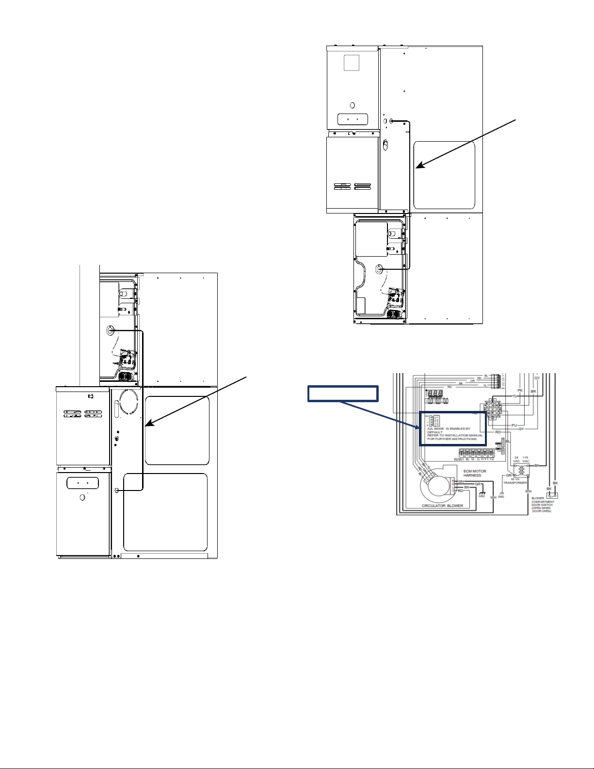
The leak detection sensor must be wired directly to the
furnace. Follow routing diagram as shown in Figures 4 or
5 depending on orientation of install. This wiring is intended
to be passed through the access hole on the furnace. If a
hole must be cut into the furnace, ensure that the wiring is
well protected from mechanical damage and that the hole is
free from burrs or sharp edges. Utilize a protective coating
for all exposed metallic edges to prevent corrosion. Verify
that the A2L function (this is required for R32 integration)
is enabled on the furnace board PCB. Refer to the furnace
IO for further instruction on how to toggle this function
described on the furnace IO must be completed before
the unit is commissioned. If the test is not successful, call
1-855-DAIKIN1, option 3, for further assistance.
Scenario 2: Amana® Brand / Goodman / Daikin Furnace or
Modular Blower PCB with no R32 sensor compatibility.
The leak detection sensor must be wired directly to the NonA2L Furnace Integration Kit and installed as a pass-through
to the non-A2L furnace control board. For instructions on
how to correctly wire the Non-A2L Furnace Integration Kit
refer to the kit IO.
This appliance is equipped with a leak detection sensor
which must be wired through the connector on the furnace
PCB or Non-A2L Furnace Integration Kit.
The R32 Sensor must be installed and powered for service.
Ensure that the grommet is installed through the access
panel knockout hole. Sensor bracket assemblies are
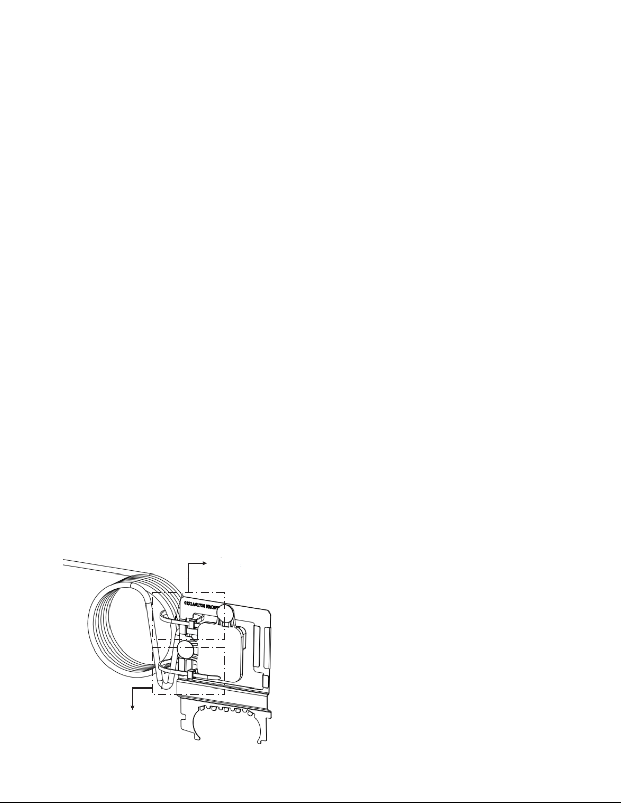
shipped with two zip ties, one of which is designed for strain
relief. The zip tie shown in Figure 1, detail A, must be kept
attached to the sensor bracket assy. Detail B highlights the
zip tie that must be cut during installation in order to release
the wire bundle.
B
A
Scenario 3: All other OEM Furnaces.
The availability of mitigation mode, or equivalent, must be
checked through the furnace model manufacturer IO. Please
follow relevant instructions to disable mitigation mode, or
equivalent. Once this step is complete follow instructions of
scenario 2. If mitigation mode, or equivalent, is present but
can't be disabled the furnace must be replaced. If mitigation
mode, or equivalent, is not available follow the instructions
on scenario 2.
Under no circumstance should the system be charged with
refrigerant at a capacity greater than the refrigerant charge
listed on the serial plate. This value indicates refrigerant
charge at or above 30% GREATER than the intended
charge with the longest line-sets.
If additional charge is required, you must contact Daikin
Comfort’s Homeowner Support Line.
5.1 Preparation
Keep this document with the unit. Carefully read all
instructions for the installation prior to installing product.
Make sure each step or procedure is understood and
any special considerations are taken into account before
starting installation. Assemble all tools, hardware and
supplies needed to complete the installation. Some items
may need to be purchased locally. Make sure everything
needed to install the product is on hand before starting.
Figure 1 - Isometric view of sensor bracket assy (back view)
2
Page 3
5.2 Clearances
Consult all appropriate regulatory codes prior to
to physical damage (i.e. a garage) it is advised to install a
protective barrier to prevent such damage. Always install
foot) is allowed.
Further, any joints made in the installation between
parts of the refrigerating system must be accessible for
maintenance purposes.
NOTE: Furnace application requires that the installer
MUST review and strictly follow ALL furnace installation
clearance guidelines. Failure to do so may result in
property / equipment damage, personal injury or death.
CONSULT ALL APPROPRIATE REGULATORY CODES
WHEN DETERMINING FINAL CLEARANCES.
WARNING
The entire system (combination of indoor and outdoor
sections) must be manufacturer approved and Air Conditioning, Heating, and Refrigeration Institute (AHRI) listed.
NOTE: Installation of unmatched systems is not
permitted.
7. Application Information
WARNING
°
Coils are designed for indoor installation only and must be
installed downstream (discharge air) of the furnace. The
orientations.
8. Condensate Drain Piping
cause damage, a secondary drain pan must be provided by
the installer and placed under the entire unit with a separate
drain line properly sloped and terminated in an area visible
to the owner. This secondary drain pan can provide extra
protection to the area under the unit should the primary
expressed in our product warranty, we will not be liable for
any damages, structural or otherwise due to the failure to
follow this installation requirement.
Condensate drain connections are located in the drain
pan at the bottom of the coil/enclosure assembly. Use the
the enclosure for external connections. The connectors
must be hand tightened to a torque of no more than 37
in-lbs. to prevent damage to the drain pan connection. An
insertion depth between .36 to .49 inches (3-5 turns) should
be expected at this torque. Insulate PVC drain lines/pipes
Foil-Mastic Sealant tape is the preferred wrapping material.
1. Ensure drain pan hole is NOT obstructed.
2.
space, it may be necessary to insulate the condensate
similar material.
A secondary condensate drain connection, now called for
by many building codes, has been provided. Pitch the drain
support to drain line to prevent bowing. Install a condensate
trap in the primary drain line to ensure proper drainage. If the
secondary drain line is required, run the line separately from
the primary drain and end it where condensate discharge
can be easily seen.
CAUTION
WARNING
3
Page 4
9. Plastic Drain Pan Application
2” MIN.
3” MIN.
C, D CHASSIS WITH 90%
C, D CHASSIS WITH 80%
WARNING
NOTE: Water coming from the secondary line means the
coil primary drain is plugged and needs immediate attention.
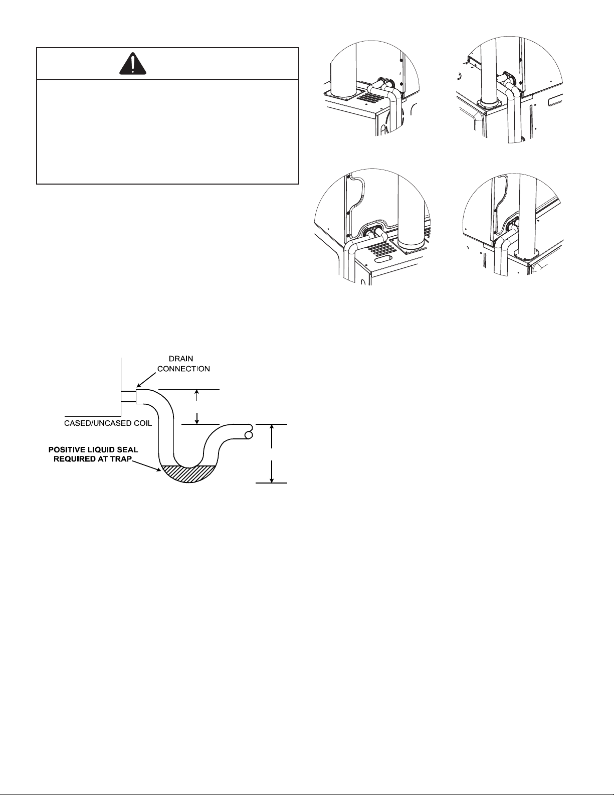
Install a trap in the drain line below the bottom of the drain
pan (Figure 2). If using a copper drain line, solder a short
piece of pipe, minimum 6” length, to the connector before
drain connection. Using a wet rag or heatsink material on
the short piece to protect the plastic drain pan, complete
the drain line installation. Use Figure 3 as a template for
interference with vent piping.
A, B CHASSIS W
ITH 80%
A, B CHASSIS W ITH 90%
Figure 3
Refer to Table 3 for minimum conditioned room area
requirements.
Figure 2
The appliance shall be stored so as to prevent mechanical
damage from occurring.
R32 sensor fault codes should be referenced through the
corresponding R32 equipped furnace or accessory IO
manuals. It is the installer’s responsibility to ensure that
mitigation mode is operational.
Sensor is not intended for service or repair. If the sensor is
not functioning properly, mitigation mode will engage and
the sensor must be replaced by removing the old sensor
from the bracket and re-installing with new push-pins
and a zip-tie. The R32 sensor shall only be replaced with
replacement part can be determined through the homeowner
support line provided earlier in this document.)
• 18 AWG
• 1.58mm insulation thickness or protected from
damage
If the sensor used in this unit must be routed through the
Non-A2L Furnace Integration Kit, then reference the NonA2L Furnace Integration Kit installation manual for further
instructions.
4
Page 5
For any and all accessories which may become a potential
ignition source, they must be installed to our accessory
control board. Ensure that any additional wiring from the
cased coil is done so as to protect from damage and wear,
brazed or disconnected for service. If a zone control system
is installed in the ductwork attached to this system, the zone
controller must be powered through a zoning kit to ensure
that the zoning dampers actuate during mitigation mode.
accessory control kit part number.
Check that wiring will not be subject to wear, corrosion,
excessive pressure, vibration, sharp edges or any other
sources such as compressors or fans.
WIRE
WIRE
A2L Sensor Input
Typical Design for Refrigerant Detection Sensor connectors.
Figure 6
5
Page 6

11. Refrigerant Lines
CAUTION
WARNING
WARNING
11.1 Standing Pressure Test (Recommended before
vacuum)
Using dry nitrogen or dry helium, pressurize the system to
460 PSIG. Allow the pressure to stabilize and hold for 15
Minutes (minimum). The system is considered leak-free
if the pressure does not drop below 460 PSIG. If, after 15
Minutes, the pressure drops below 460 PSIG, it implies a
leak in the system. Proceed with identifying and sealing
the leak and repeating the Standing Pressure Test. Leak
test the system using dry nitrogen or dry helium and
soapy water to identify leaks. No refrigerant shall be used
for pressure testing to detect leaks. Proceed to system
evacuation using the Deep Vacuum Method.
11.2 Deep Vacuum Method
The Deep Vacuum Method requires a vacuum pump
air and moisture. The Triple Evacuation Method is
detailed in the Service Manual for this product model as
an alternative. To expedite the evacuation procedure, it is
recommended that the Schrader Cores be removed from
the service valves using a core-removal tool.
WARNING
NOTE: Refrigerant tubing must be routed to allow adequate
access for servicing and maintenance of the unit.
Doing so may result in damage to the tubing joints. Always
use clean gloves for handling coil assemblies.
Follow standards related to ASHRAE 15, ASHRAE 15.2,
IAPMO Uniform Mechanical Code, ICC International
Mechanical Code or CSA B52 during any installation. Piping
must be accessible for inspection prior to being covered or
enclosed in compliance with national and local codes.
The indoor equipment and pipes must be securely mounted
and guarded such that accidental rupture of equipment
cannot occur from such events as moving furniture or
reconstruction activities. Field-made refrigerant joints
indoors shall be tightness tested. The test method shall have
a sensitivity of 5 grams per year of refrigerant or better under
a pressure of at least 0.25 times the maximum allowable
pressure. No leak shall be detected (Should be leak tight).
Field pipework must be pressure tested with an inert gas and
then vacuum tested prior to refrigerant charging according
to the following requirements:
1. Connect the vacuum pump, micron gauge, and
vacuum-rated hoses to both service valves. Evacuation
must use both service valves to eliminate system
mechanical seals.
2. Evacuate the system to less than 500 microns.
3. Isolate the pump from the system and hold the vacuum
for 10 minutes (minimum). Typically, pressure will rise
slowly during this period. If the pressure rises to less
than 1000 microns and remains steady, the system is
considered leak-free; proceed to system charging and
startup.
4. If pressure rises above 1000 microns but holds steady
below 2000 microns, non-condensable air or moisture
may remain, or a small leak may be present. Return to
step 2: If the same result is achieved, check for leaks and
repair. Repeat the evacuation procedure.
5. If pressure rises above 2000 microns, a leak is
present. Check for leaks and repair them. Then, repeat
the evacuation procedure.
11.3 Tubing Size/Length
the condenser/heat pump. Give special consideration
to minimizing the length of refrigerant tubing when
installing coils. Refer to Remote Cooling/Heat Pump
Technical Publication TP-110* Long Line Set Application
for guidelines for line lengths over 80’. Leave a minimum
3” straight in line set from braze joints before any bends.
6
Page 7
11.4 Tubing Preparation
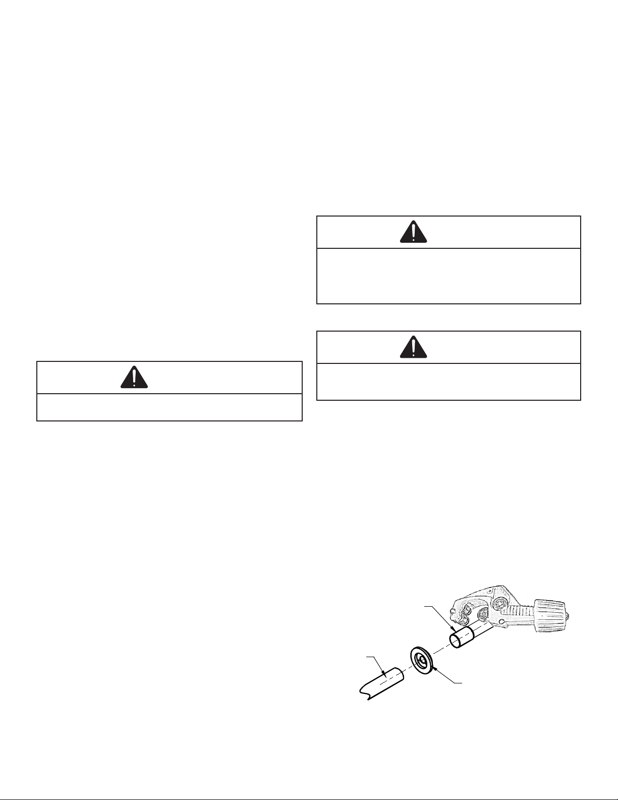
SUCTION
LINE SET
SUCTION
TUBE
RUBBER
GROMMET
All cut ends are to be round, burr free, and cleaned. Any
other condition increases the chance of a refrigerant
leak. Use a pipe cutter to remove the closed end of the
spun closed suction line.
Installation of pipe-work must be kept to a minimum. Pipework including piping material, pipe routing and installation
must be protected from physical damage and shall not
be installed in an unventilated space. Equipment piping
in any occupied space shall be installed in such a way to
protect against accidental damage in operation and service.
Precautions must be taken to avoid excessive vibration
or pulsation to refrigeration piping. Protection devices,
danger of water collecting and freezing in relief pipes or the
accumulation of dirt and debris. Steel pipes and components
shall be protected against corrosion with a rustproof coating
before applying any insulation. Any solenoid valves and
piping in the refrigerant systems must be so designed
and installed to minimize the likelihood of hydraulic shock
damaging the system. Solenoid valves must not block in
liquid refrigerant unless adequate relief is provided to the
refrigerant system’s low pressure side. Provisions must be
made for expansion and contraction of long runs of piping.
WARNING
11.5 Brazing
Braze joints should be made only with the connections
provided external to the cabinet. Do not alter the cabinet
nor braze inside the cabinet. To avoid overheating after
brazing, quench all brazed joints with water or a wet rag.
This system must be charged with R32 refrigerant in
order to operate safely.
When breaking into the refrigerant circuit to make repairs
– or for any other purpose – conventional procedures
it is important that best practice be followed, since
shall be adhered to:
refrigerants purging shall be achieved by breaking the
vacuum in the system with oxygen-free nitrogen and
to a vacuum (optional for R32). This process shall be
repeated until no refrigerant is within the system (optional
used, the system shall be vented down to atmospheric
pressure to enable work to take place.
The outlet for the vacuum pump shall not be close to
any potential ignition sources, and ventilation shall be
available.
CAUTION
11.6 Tubing Connections for TXV Version
WARNING
TXV models come with factory installed adjustable TXV
with the bulb permanently located on the suction tube.
1. Remove coil access panel and rubber grommets.
2.
pressure indicates possible leak.
3. Reinstall the Coil Access Panel & rubber grommets.
4. Remove the spin closure on both the liquid and
suction tubes using a tubing cutter. DO NOT USE
A CUTTING METHOD THAT WOULD RESULT IN
THE GENERATION OF COPPER SHAVINGS OR
COPPER DUST.
1. Safely remove refrigerant following local and national
regulations;
2. Evacuate;
3. Purge the circuit with inert gas;
4. Evacuate;
5.
6. Open the circuit.
Figure 7A
7
Page 8
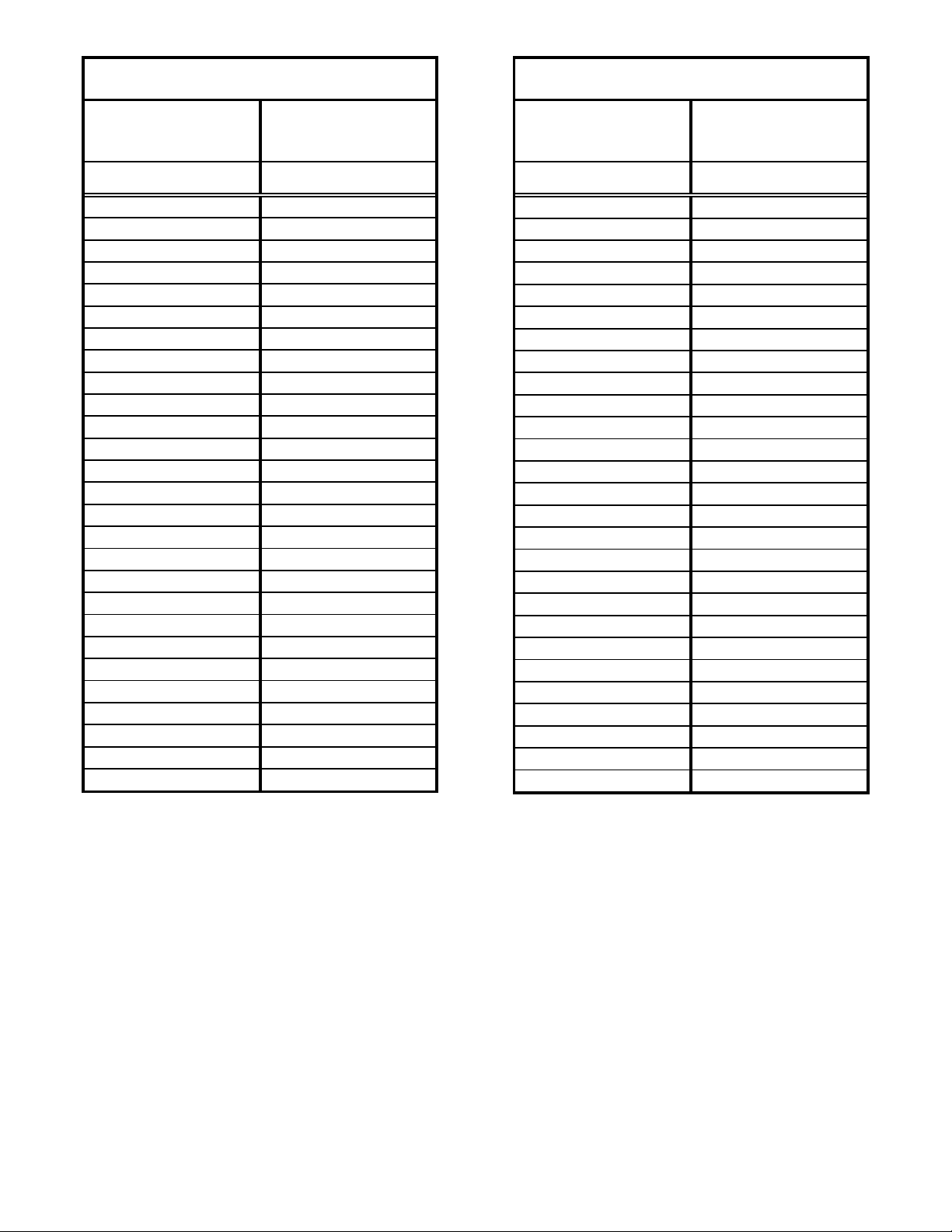
Suction Pressure
52
2.06
54
3.51
56
4.94
58
6.33607.69
62
9.03
64
10.34
66
11.62
68
12.88
70
14.12
72
15.34
74
16.53
76
17.70
78
18.86
80
19.99
85
22.75
90
25.41
95
27.97
100
30.44
110
35.16
120
39.59
130
43.79
140
47.76
150
51.55
160
55.17
170
58.64
Saturated Suction Pressure
Temperature Chart
210
71.23
220
74.11
225
75.50
235
78.25
245
80.91
255
83.50
265
86.03
275
88.48
285
90.86
295
93.19
305
95.46
325
99.85
355
106.08
375
110.02
405
115.65
415
117.46
425
119.24
435
120.98
445
122.70
475
127.68
500
131.65
525
135.48
550
139.17
575
142.73
600
146.17
625
149.50
Saturated Liquid Pressure
Temperature Chart
Saturated Suction
Temperature ºF
Suction Pressure
Saturated Liquid
Temperature ºF
PSIG R32
50 0.57
PSIG R32
200 68.25
Table 1
Table 2
8
Page 9
CC
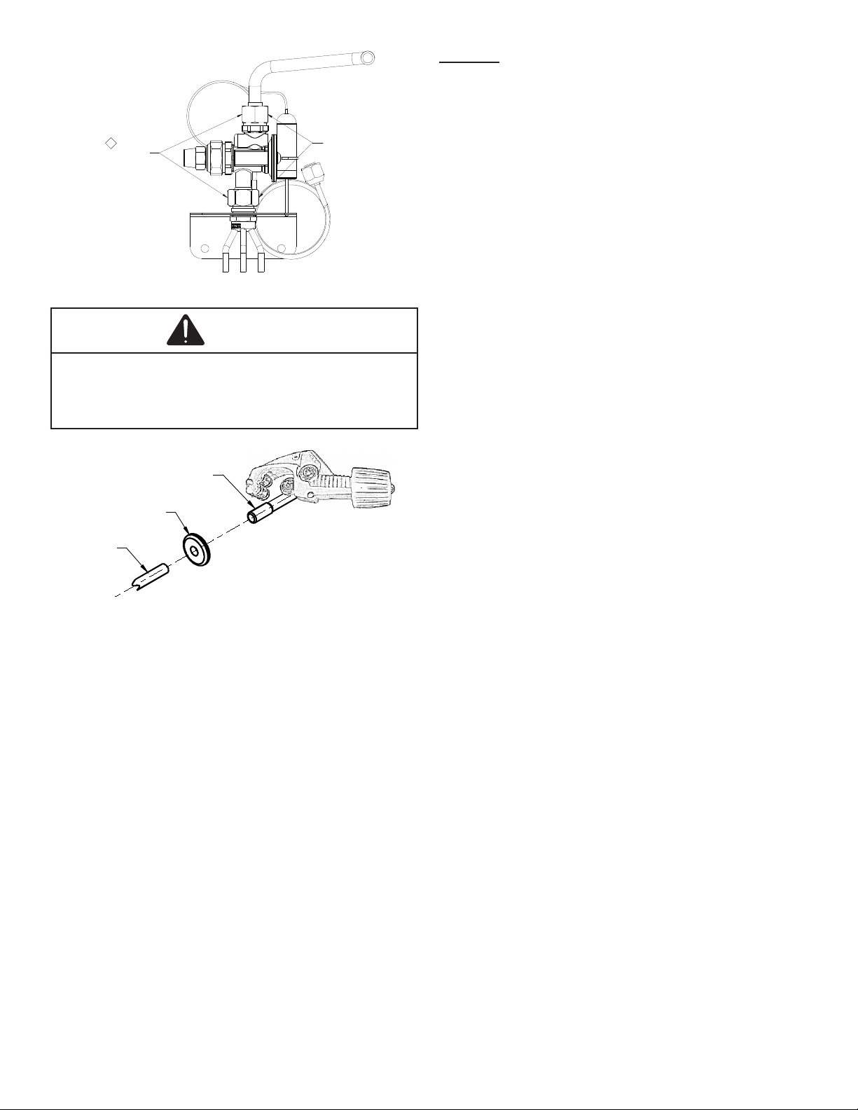
LIQUID
LINE SET
LIQUID
LINE
RUBBER
GROMMET
TORQUE 180-240 IN-LBS
ENSURE THAT SEAL
WASHERS STAY
IN POSITION
CAUTION
24 hours depending on indoor temperature and humidity.
Before checking superheat run the unit in cooling for 10
minutes or until refrigerant pressures stabilize. Use the
following guidelines and methods to check unit operation
and ensure that the refrigerant charge is within limits. NOTE:
Charge two stage units on low stage.
In addition to conventional charging procedures, the
following requirements shall be followed:
1.
does not occur when using charging equipment. Hoses
or lines shall be as short as possible to minimize the
amount of refrigerant contained in them.
2. A2L refrigerant cylinders shall be kept in an appropriate
position according to the instructions.
3. Ensure that the refrigeration system is grounded prior
to charging the system with refrigerant.
4. Label the system when charging is complete (if not
already).
5.
refrigerating system.
Prior to recharging the system, it shall be pressure-tested
with the appropriate purging gas. The system shall be leaktested on completion of charging but prior to commissioning.
A follow up leak test shall be carried out prior to leaving the
site.
Figure 7C
5. Insert liquid line set into liquid tube expansion and
slide grommet about 18” away from braze joint.
6. Insert suction line set into suction tube expansion and
slide insulation and grommet about 18” away from
braze joint.
7. Braze suction and liquid line joints.
11.7 Thermal Expansion Valve System Adjustment
The following information for the indoor unit should be
if necessary.
1. Total static pressure is .5” WC or less.
2.
3.
Sheet for Indoor Unit.
4.
in Service Manual.
5. The outdoor temperature must be 60°F or higher.
6. Set the room thermostat to COOL, fan switch to AUTO
7. Set the temperature control well below room
temperature.
Superheat adjustments should not be made until indoor
ambient conditions have stabilized. This could take up to
1. Purge gauge lines. Connect service gauge manifold to
base-valve service ports.
2. Temporarily install a thermometer on the liquid line at the
liquid line service valve and 4-6” from the compressor
on the suction line. Ensure the thermometer makes
adequate contact and is insulated for best possible
readings. Use liquid line temperature to determine
subcooling and vapor temperature to determine
superheat.
3. If subcooling and superheat are low, adjust TXV
Outdoor Installation and Instruction manual.
a. If subcooling is low and superheat is high, add
charge to raise subcooling 8°F +/- 1°F then, check
superheat.
b. If subcooling and superheat are high, adjust TXV
Outdoor Installation and Instruction manual.
4. After adjustments are complete reinstall cap on
adjustment stem and tighten 1/6 turn.
5. Remove gauges and check the Schrader ports for
leaks and tighten valve cores if necessary. Install caps
For optimum system performance subcool and superheat
and Instruction manual. Outdoor should be matched with
approved AHRI combination, other approved system shall
have subcooling set to 8°F ± 1°F and superheat set to 12°F
± 1°F.
9
Page 10
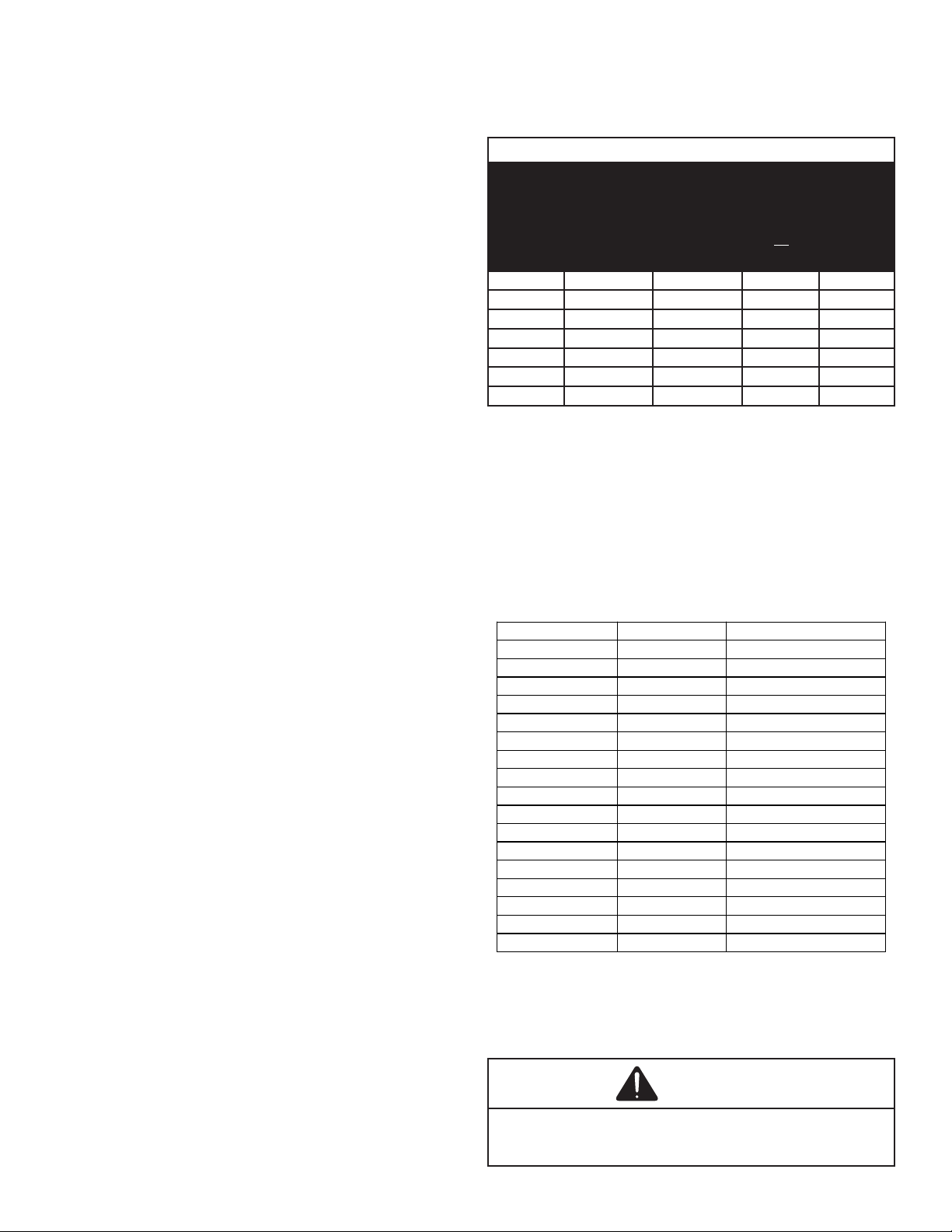
NOTE: The minimum time between TXV adjustments shall
Altit ude Adjustment Factor (AF)
1.00At sea levelAt sea level
1.021~6601~200
1.03660~1320200~400
1.051320~1970400~600
1.071970~2630600~800
1.092630~3290800~1000
1.113290~39401000~1200
1.133940~46001200~1400
1.154600~52501400~1600
1.175250~59101600~1800
1.195910~65701800~2000
1.216570~72202000~2200
1.247220~78802200~2400
1.267880~85402400~2600
1.298540~91902600~2800
1.319190~98502800~3000
1.349850~105003000~3200
be 20 minutes.
NOTE: In situations where the TXV must be removed and
replaced or re-installed into the system, the TXV should be
TXV. No more than 20 ft-lb torque should be applied to the
joints of the TXV.
NOTE: Do NOT adjust the charge based on suction pressure
unless there is a gross undercharge.
12. Altitude adjustment factor to calculate
min room area.
The Indoor equipment mitigation requirements, as seen on
table 3, are calculated at sea level.
3
m
hr
Conditioned
Room Area
(m²)
Conditioned
Room Area
(ft²)
11.8 Piston Charge Instructions
If the unit is not equipped with a TXV metering device
follow the steps below:
1. Ensure the piston size present on the unit is rated for
use with the outdoor matchup as shown on the piston
kit chart. If it does not match, replace the provided
piston with the piston size listed on the piston kit chart.
2. For optimum system performance, superheat should
with respective AHRI outdoor matchup.
11.9 Leak Detection
Under no circumstances shall potential sources of ignition
be used in the searching for or detection of refrigerant leaks.
shall be removed/extinguished. If a leakage of refrigerant is
found which requires brazing, all of the refrigerant shall be
valves) in a part of the system remote from the leak.
1.5T Match-up 13.26 142.68 437.43 257.46
2.0T Match-up 13.47 145.03 444.63 261.70
2.5T Match-up 14.46 155.60 477.05 280.78
3.0T Match-up 17.27 185.87 569.85 335.40
3.5T Match-up 18.91 203.49 623.87 367.20
4.0T Match-up 20.32 218.77 670.69 394.75
5.0T Match-up 20.87 224.64 688.70 405.35
It is the installer’s responsibility to verify that actuation
of mitigation procedures are operational with minimum
Table 3
on the Serial Plate by the corresponding altitude adjustment
factor shown below. This table is provided as a reference.
Adjusted room area (Amin adj) is the product of the minimum
factor AF, as shown in below formula
Amin adj = Amin (serial plate) * AF
The following leak detection methods have been deemed
acceptable, provided proper care is taken in their
implementation:
1. Electronic leak detectors rated for use with R32
refrigerant. Ensure the detection equipment is
calibrated in a refrigerant-free area and that the leak
detector itself is not a potential source of ignition. Leak
detection equipment shall be set at a value of no more
then 0.075 kg/m³.
2.
containing chlorine are avoided as the chlorine may
react with the refrigerant and corrode the pipe-work.
13. Supply Duct Connection
10
Table 4 - A_min altitude correction factor.
WARNING
Page 11
For appliances using A2L REFRIGERANTS, connected via
an air duct system to one or more rooms, the supply and
return air shall be directly ducted to the space. Open areas
such as false ceilings shall not be used as a return air duct
The air extraction opening from the room shall be located
mounted units, it shall be as low as practicable. The air
from the air intake openings to prevent re-circulation to the
space.
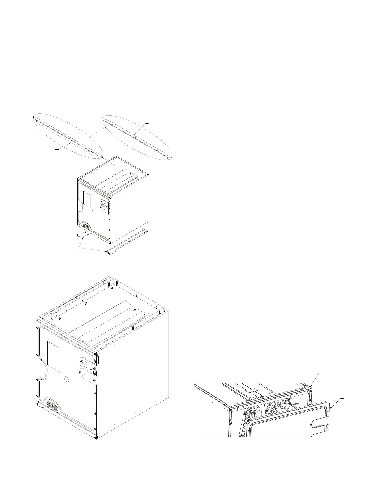
FLANGE UNFOLDED UP
FLANGE BENT DOWN
14. Furnace to Coil Attachment
Refer to the Furnace IO manual for further instruction. Attach
and furnace combination are not similar in depth and width,
openings.
1. Using the hardware and brackets provided, attach the
coil to the furnace then attach the plenum to the coil. Using
tape or mastic seal between the coil and furnace and the coil
and plenum.
15. Filler Plates
Filler plates are supplied on all 17.5, 21, & 24.5 inch chassis
to be used for adapting the unit to a furnace one size smaller.
If the plenum and furnace openings are the same size, the
distributor. (See Figure 9)
• 14 inch chassis - CLDUCTFLGA
• 17.5 inch chassis - CLDUCTFLGB
• 21 inch chassis - CLDUCTFLGC
• 24.5 inch chassis - CLDUCTFLGD
FILLER PLATE
Figure 8
16. Return Ductwork
DO NOT TERMINATE THE RETURN DUCTWORK
IN AN AREA THAT CAN INTRODUCE TOXIC OR
OBJECTIONABLE FUMES/ODORS INTO THE
DUCTWORK.
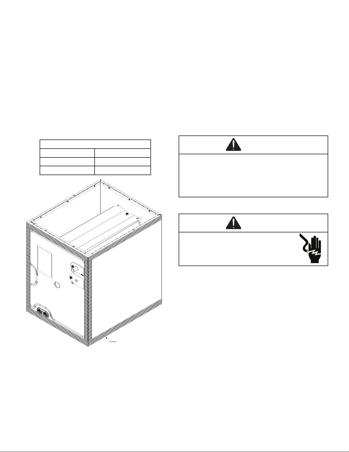
17. Sealing Along The Panel Gap
To prevent cabinet sweating and
joining surfaces between the coil, gas furnace, duct work
and panels. See Figure 11.
18. Removing Coil from Cabinet
In an event of removing taller coils from cabinet to service
or replace; remove access panel, remove top tie rail to allow
the coils to slide out of the cabinet.
After service or replacement slide the coil back in the cabinet
and secure the top tie rail and re-install access panel.
See Figure 10.
TOP TIE
Figure 9
PANEL
11
Page 12
the only models approved to be used with this unit. They
can be purchased from the distributors. The use of the
accessory control kit is optional for the installation of this
models. Maximum UV lamp diameter to be used per delta
plate knockout design is 1.375” to reduce the possibility of
air leak.
The power source must be installed external of the unit.
Ensure that the wiring is routed through the access panel
knockout with the grommet included. The magnetic door
switch must be installed to avoid any accidental Ultraviolet
exposure during service.
manual for additional details.
It has been determined that many coil cleaners and drain
pan tablets contain corrosive chemicals that can be harmful
time application of these corrosive chemicals can cause
premature aluminum evaporator coil failure. Any cleaners
that contain corrosive chemicals including, but not limited
to, chlorine and hydroxides, should not be used.
An alternate cleaning method is to use one of the products
listed in TP-109* to clean the coils. The cleaners listed are
the only agents deemed safe and approved for use to clean
round tube aluminum coils. TP-109 is also available on the
web site in Partner Link > Service Toolkit.
NOTE: Ensure coils are rinsed well after use of any chemical
cleaners.
Lamp
UC18S15-24 UCP-16013
UC18S15-24B UCP-16012
APPLY INSULATION TAPE
Figure 11
R32 sensor must be removed from the unit before
applying coil cleaners to avoid damage and contamination.
Reassemble the R32 sensor back to the unit after done
with coil cleaning process. This unit is equipped with an
aluminum tube evaporator coil. The safest way to clean the
cleaning practice remains as the recommended cleaning
method for both copper tube and aluminum tube residential
evaporator coils.
WARNING
21. Start-Up Procedure
WARNING
• Prior to start-up, ensure that all electrical wires are
properly sized and all connections are properly
tightened.
• All panels must be in place and secured. For air tight
application, gasket must be positioned at prescribed
locations to achieve 1.4% leakage.
• Tubing must be leak free.
• Condensate line must be trapped and pitched to allow
for drainage.
• Low voltage wiring is properly connected.
• Auxiliary drain is installed when necessary and
pitched to allow for drainage.
• Unit is protected from vehicular or other physical
damage.
• Return air is not obtained from, nor are there any
return air duct joints that are unsealed in, areas where
or products of combustion such as carbon monoxide
(CO), which may cause serious personal injury or
death.
• Ensure that the equipped R32 sensor is wired to
the furnace PCB and that there are no sources of
potential ignition within the system.
12
Page 13
the furnace IO or the Non-A2L Integration Kit IO must be
completed.
22. Refrigerant Recovery
When removing refrigerant from a system, either for
servicing or decommissioning, it is recommended good
practice that all refrigerants are removed safely. When
transferring refrigerant into cylinders, ensure that only
appropriate refrigerant recovery cylinders are employed.
Ensure that the correct number of cylinders for holding the
total system charge are available. All cylinders to be used
are designated for the recovered refrigerant and labeled
for that refrigerant (i.e. special cylinders for the recovery of
refrigerant). Cylinders shall be complete with pressure-relief
Empty recovery cylinders are evacuated and, if possible,
cooled before recovery occurs.
The recovery equipment shall be in good working order
with a set of instructions concerning the equipment that
is at hand and shall be suitable for the recovery of the
be consulted. In addition, a set of calibrated weighing scales
shall be available and in good working order. Hoses shall be
complete with leak-free disconnect couplings and in good
condition. The recovered refrigerant shall be processed
according to local legislation in the correct recovery cylinder,
and the relevant waste transfer note arranged. Do not mix
refrigerants in recovery units and especially not in cylinders.
•
• Wait 15 minutes. Some devices in the outdoor unit or
in programmable thermostats will prevent compressor
operation for awhile, and then reset automatically. Also,
some power companies will install devices which shut
you wait several minutes, the unit may begin operation
on its own.
• Check the electrical panel for tripped circuit breakers or
failed fuses. Reset the circuit breakers or replace fuses
as necessary.
• Check the disconnect switch near the indoor furnace or
•
it has not been covered on the sides or the top. Remove
any obstructions that can be safely removed. If the unit
clean it.
• Check for blockage of the indoor air inlets and outlets.
by objects (rugs, curtains or furniture).
•
• Listen for any unusual noise(s), other than normal
operating noise, that might be coming from the outdoor
unit. If you hear unusual noise(s) coming from the unit,
If compressors or compressor oils are to be removed,
ensure that they have been evacuated to an acceptable
remain within the lubricant. The compressor body shall not
accelerate this process. When oil is drained from a system,
it shall be carried out safely.
13
Page 14
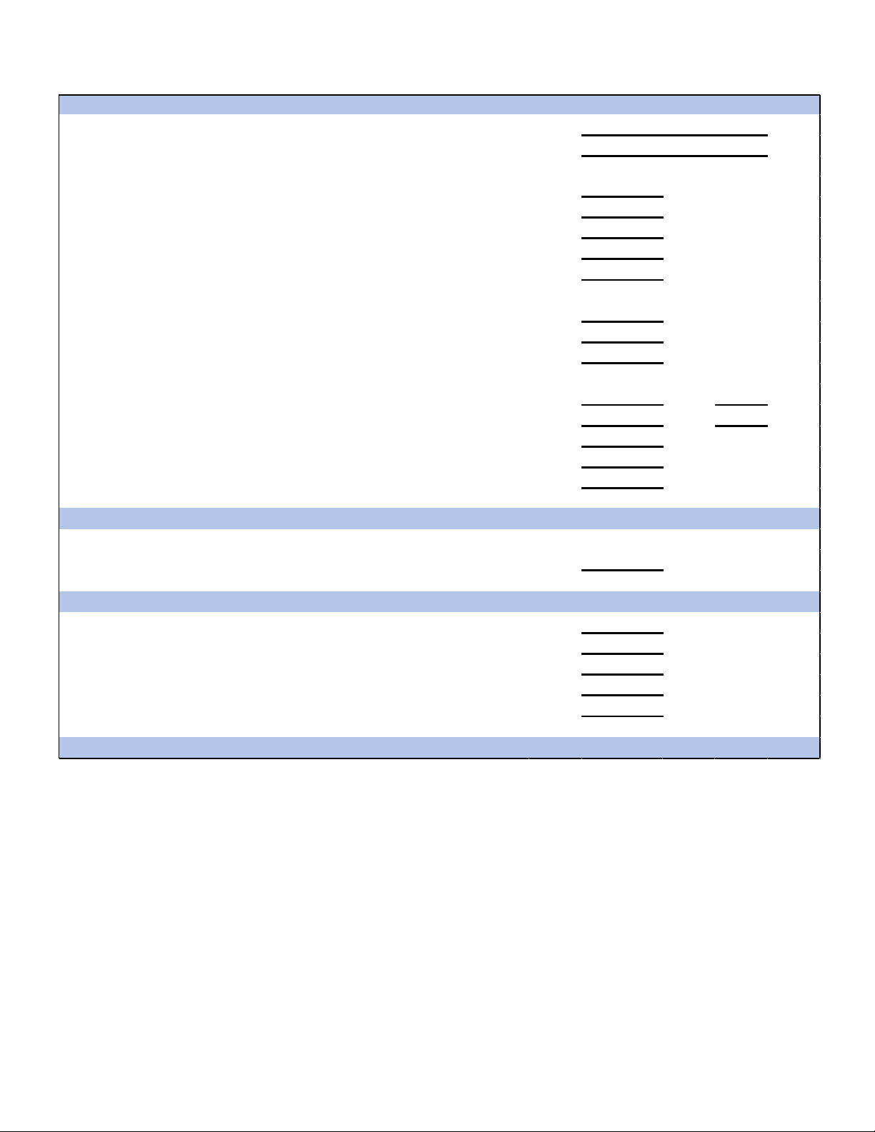
Air Handler / Coil
Model Number
Serial Number
Cooling Supply Air Temperature (Dry bulb / Wet bulb)
24. Start-Up Checklist
Line Voltage (Measure L1 and L2 Voltage) L1 - L2
Secondary Voltage (Measure Transformer Output Voltage) R - C
Blower Amps
Heat Strip 1 - Amps
Heat Strip 2 - Amps
Return Air Sta�c Pressure IN. W.C.
Supply Air Sta�c Pressure IN. W.C.
Total External Sta�c Pressure (Ignoring +/- from the reading above, add total here) IN. W.C.
Return Air Temperature (Dry bulb / Wet bulb)
Hea�ng Supply Air Temperature DB °F
Temperature Rise DB °F
Delta T (Difference between Supply and Return Temperatures) DB °F
ELECTRICAL
BLOWER EXTERNAL STATIC PRESSURE
TEMPERATURES
DB °F WB °F
DB °F WB °F
Air Handler / Coil - (Inverter Matched)
INVERTER AH / COIL ONLY
Check EEV and EEV wiring is secure (no adjustment required)
Addi�onal Checks
Check wire rou�ngs for any rubbing
Check product for proper draining
Check screw �ghtness on blower wheel
Check factory wiring and wire connec�ons
Check product for proper clearances as noted by installa�on instruc�ons
°F to °C formula: (°F - 32) divided by 1.8 = °C °C to °F formula: (°C mul�plied by 1.8) + 32 = °F
14
Page 15

15
Page 16
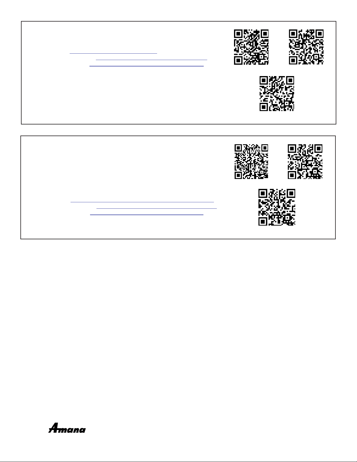
CUSTOMER FEEDBACK
We are very interested in all product comments.
Daikin Products: (https://daikincomfort.com/contact-us)
Goodman® Brand Products: (http://www.goodmanmfg.com/about/contact-us).
Amana® Brand Products: (http://www.amana-hac.com/about-us/contact-us).
You can also scan the QR code on the right for the product brand you
purchased to be directed to the feedback page.
PRODUCT REGISTRATION
Thank you for your recent purchase. Though not required to get the
protection of the standard warranty, registering your product is a relatively
short process, and entitles you to additional warranty protection, except that
failure by California, Florida, and Quebec residents to register their product
does not diminish their warranty rights. The duration of warranty coverages in
For Product Registration, please register as follows:
Daikin Products: (https://daikincomfort.com/owner-support/product-registration).
Goodman® Brand products: (https://www.goodmanmfg.com/product-registration).
Amana® Brand products: (http://www.amana-hac.com/product-registration).
You can also scan the QR code on the right for the product brand you purchased
to be directed to the Product Registration page.
DAIKIN
AMANA® BRAND
DAIKIN
AMANA® BRAND
GOODMAN® BRAND
GOODMAN® BRAND
NOTE: SPECIFICATIONS AND PERFORMANCE DATA LISTED HEREIN ARE SUBJECT TO CHANGE WITHOUT NOTICE
19001 Kermier Rd., Waller, TX 77484
© 2023-2024 Daikin Comfort Technologies Manufacturing, L.P.
www.daikincomfort.com • www.goodmanmfg.com • www.amana-hac.com
®
is a registered trademark of Maytag Corporation or its related companies and is used
under license. All rights reserved.
16
 Loading...