

Goodman GSH140181AA, ASH130181AA, GSH100903AB, GSH140181AB, ASH130181AB Service Instructions Manual
...Page 1
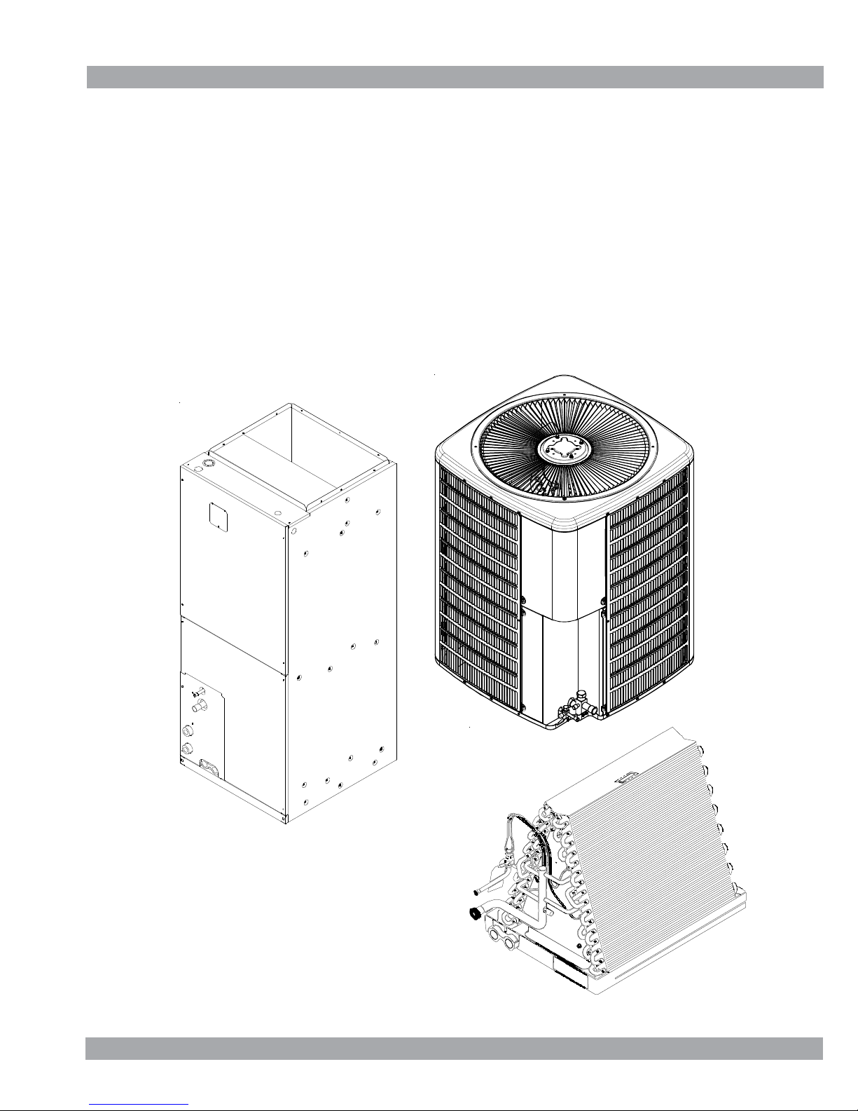
Service Instructions
Split System Air Conditioners,
Split System Heat Pumps
with R-22 Refrigerant
Blowers, Coils, & Accessories
This manual is to be used by qualified, professionally trained HVAC
technicians only. Goodman does not assume any responsibility for
property damage or personal injury due to improper service
procedures or services performed by an unqualified person.
Copyright © 2005 - 2009 Goodman Manufacturing Company, L.P.
RT6100004r13
May 2009
Page 2

This manual is for the follow model numbers
GSH100903AA GSH140181AA ASH130181AA
GSH100903AB GSH140181AB ASH130181AB
GSH100904AA GSH140241AA ASH130181AC
GSH100904AB GSH140241AB ASH130241AA
GSH101203AA GSH140241AC ASH130241AB
GSH101203AB GSH140301AA ASH130241AC
GSH101204AA GSH140301AB ASH130241AD
GSH101204AB GSH140301AC ASH130301AA
GSH140361AA ASH130301AB
GSH130181AC GSH140361AB ASH130301AC
GSH130181BA GSH140361AC ASH130301AD
GSH130191AC GSH140361AD ASH130361AA
GSH130241AC GSH140361AE ASH130361AB
GSH130241BA GSH140361AF ASH130361AC
GSH130251AC GSH140421AA ASH130361AD
GSH130251AE GSH140421AB ASH130601AC
GSH130301AC GSH140421AC ASH130421AA
GSH130301BA GSH140421AD ASH130421AB
GSH130311AC GSH140481AA ASH130421AC
GSH130311AE GSH140481AB ASH130481AA
GSH130361AC GSH140481AC ASH130481AB
GSH130361AD GSH140481AD ASH130481AC
GSH130361BA GSH140601AA ASH130601AA
GSH130361BB GSH140601AB ASH130601AB
GSH130363AC GSH140601AC
GSH130363AD GSH140601AE VSH130181AA
GSH130421AC VSH130191AA
GSH130421AD VSH130241AA
GSH130421AE VSH130251AA
GSH130481AC VSH130301AA
GSH130481AD VSH130311AA
GSH130483AC VSH130361AA
GSH130483AD VSH130421AA
VSH130481AA
VSH130601AA
Page 3

This manual contain the following
IMPORTANT INFORMATION
MODEL IDENTIFICATION
AIR HANDLER/COIL IDENTIFICATION
ACCESSORIES
PRODUCT DESIGN
SYSTEM OPERATION
TROUBLESHOOTING CHART
SERVICING TABLE OF CONTENTS
SERVICING TABLE OF CONTENTS
ACCESSORIES WIRING DIAGRAMS
WIRING FOR HEAT PUMP OR AIR CONDITIONING
PARTS DIAGRAM FOR HEAT PUMP OR AIR CONDITIONING
Page 4
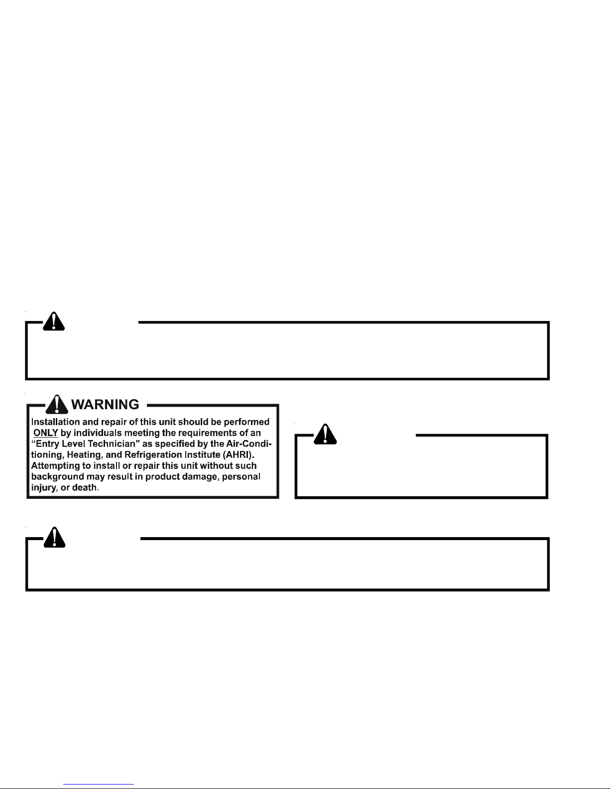
TABLE OF CONTENTS
IMPORTANT INFORMATION .........................2 - 3
MODEL IDENTIFICATION............................4 - 15
AIR HANDLER/COIL IDENTIFICATION ............15
ACCESSORIES......................................... 16 - 20
PRODUCT DESIGN ................................. 21 - 22
SYSTEM OPERATION ..............................23 - 27
TROUBLESHOOTING CHART .........................28
SERVICING TABLE OF CONTENTS ................29
SERVICING .................................................30 - 60
ACCESSORIES WIRING DIAGRAMS ........61 - 69
IMPORTANT INFORMATION
Pride and workmanship go into every product to provide our customers with quality products. It is possible, however,
that during its lifetime a product may require service. Products should be serviced only by a qualified service technician
who is familiar with the safety procedures required in the repair and who is equipped with the proper tools, parts, testing
instruments and the appropriate service manual. REVIEW ALL SERVICE INFORMATION IN THE APPROPRIATE
SERVICE MANUAL BEFORE BEGINNING REPAIRS.
IMPORTANT NOTICES FOR CONSUMERS AND SERVICERS
RECOGNIZE SAFETY SYMBOLS, WORDS AND LABELS
WARNING
This unit should not be connected to, or used in conjunction with, any devices that are not design certified for use with
this unit or have not been tested and approved by Goodman. Serious property damage or personal injury, reduced unit
performance and/or hazardous conditions may result from the use of devices that have not been approved or certified by
Goodman.
WARNING
To prevent the risk of property damage, personal
injury, or death, do not store combustible materials or
use gasoline or other flammable liquids or vapors
in the vicinity of this appliance.
WARNING
Good ma n will not be respo nsible for any injury or prop erty dam age arising from imprope r service or service
procedures. If you perform service o n your own product, you assum e responsibility for any personal inju ry or property
dam age wh ich may result.
To locate an authorized servicer, please consult your telephone book or the dealer from whom you purchased this
product. For further assistance, please contact:
CONSUMER INFORMA TION LINE
GOODMAN® BRAND PRODUCTS
TOLL FREE 1-877-254-4729 (U.S. only)
email us at: customerservice@goodmanmfg.com
fax us at: (713) 856-1821
(Not a technical assistance line for dealers.)
email us at: hac.consumer.affairs@amanahvac.com
CONSUMER INFORMATION LINE
AMANA® BRAND PRODUCTS
TOLL FREE 1-877-254-4729 (U.S. only)
fax us at: (931) 438- 4362
(Not a technical assistance line for dealers.)
Outside the U.S., call 1-713-861-2500. (Not a technical assistance
line for dealers.) Your telephone company will bill you for the call.
2
Outside the U.S., call 1-931-433-6101. (Not a technical assistance
line for dealers.) Your telephone company will bill you for the call.
Page 5
IMPORTANT INFORMATION
SAFE REFRIGERANT HANDLING
While these items will not cover every conceivable situation, they should serve as a useful guide.
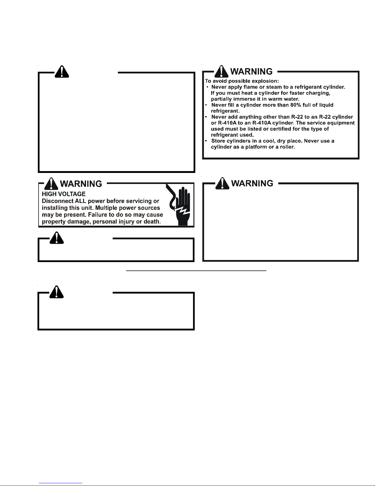
WARNING
Refrige rants are heavier than ai r. T hey can "push out"
the oxygen in your lungs or in any enclosed space.To
avoid possible difficulty in breathing or death:
•
Never purge refrigerant into an enclosed room or
space. By law, all refrigerants must be reclaimed.
•
If an in door leak is suspec ted, t horo ughl y vent ilat e
th e ar ea b ef ore b egi nn i ng w or k.
• Liqui d ref ri ge ra nt can be ver y co l d. To av oi d pos si ble
frostbit e or blind ness , avoi d co ntac t wi th re fri geran t
and wear gloves and goggles. If li quid refrigerant
does cont act your skin or eyes , s eek me dica l hel p
immediate ly.
• Always follow EPA regulations. Never burn refrig erant, as poisonous gas will be produced.
To avoid possible explosion, us e only returnable (not
disposable) service cylinders when removing refrigerant from a s yst em.
• Ensure the cy linder is free of damage which could
lead to a leak or explosion.
• Ensure the hydrostatic test date does no t exceed
WARNING
To avoid possible injury, explosion or death, practice
safe handling of refrigerants.
5 years.
• Ensure the pressure rating meets or exceeds 400
lbs.
When in doubt, do not use cylinder.
WARNING
System contamina nts, improper se rvice procedure
and/or physical abuse affecting hermetic com pressor
electrical terminals may cause dangerous s ystem
venting.
The successful development of hermetically sealed refrigeration compressors has completely sealed the compressor's
moving parts and electric motor inside a common housing,
minimizing refrigerant leaks and the hazards sometimes
associated with moving belts, pulleys or couplings.
Fundamental to the design of hermetic compressors is a
method whereby electrical current is transmitted to the
compressor motor through terminal conductors which pass
through the compressor housing wall. These terminals are
sealed in a dielectric material which insulates them from the
housing and maintains the pressure tight integrity of the
hermetic compressor. The terminals and their dielectric
embedment are strongly constructed, but are vulnerable to
careless compressor installation or maintenance procedures and equally vulnerable to internal electrical short
circuits caused by excessive system contaminants.
In either of these instances, an electrical short between the
terminal and the compressor housing may result in the loss
of integrity between the terminal and its dielectric embedment. This loss may cause the terminals to be expelled,
thereby venting the vaporous and liquid contents of the
compressor housing and system.
A venting compressor terminal normally presents no danger
to anyone, providing the terminal protective cover is properly
in place.
If, however, the terminal protective cover is not properly in
place, a venting terminal may discharge a combination of
(a ) hot lubricating oil and refrigerant
(b ) flammable mixture (if system is contaminated
with air)
in a stream of spray which may be dangerous to anyone in the
vicinity. Death or serious bodily injury could occur.
Under no circumstances is a hermetic compressor to be
electrically energized and/or operated without having the
terminal protective cover properly in place.
See Service Section S-17 for proper servicing.
3
Page 6
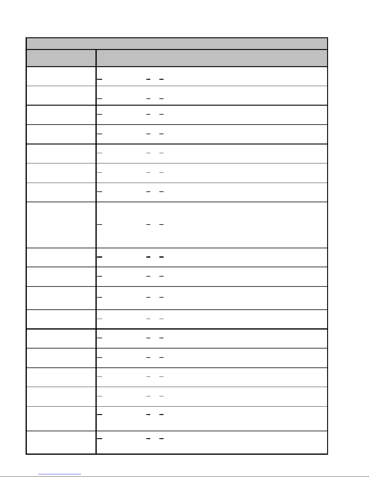
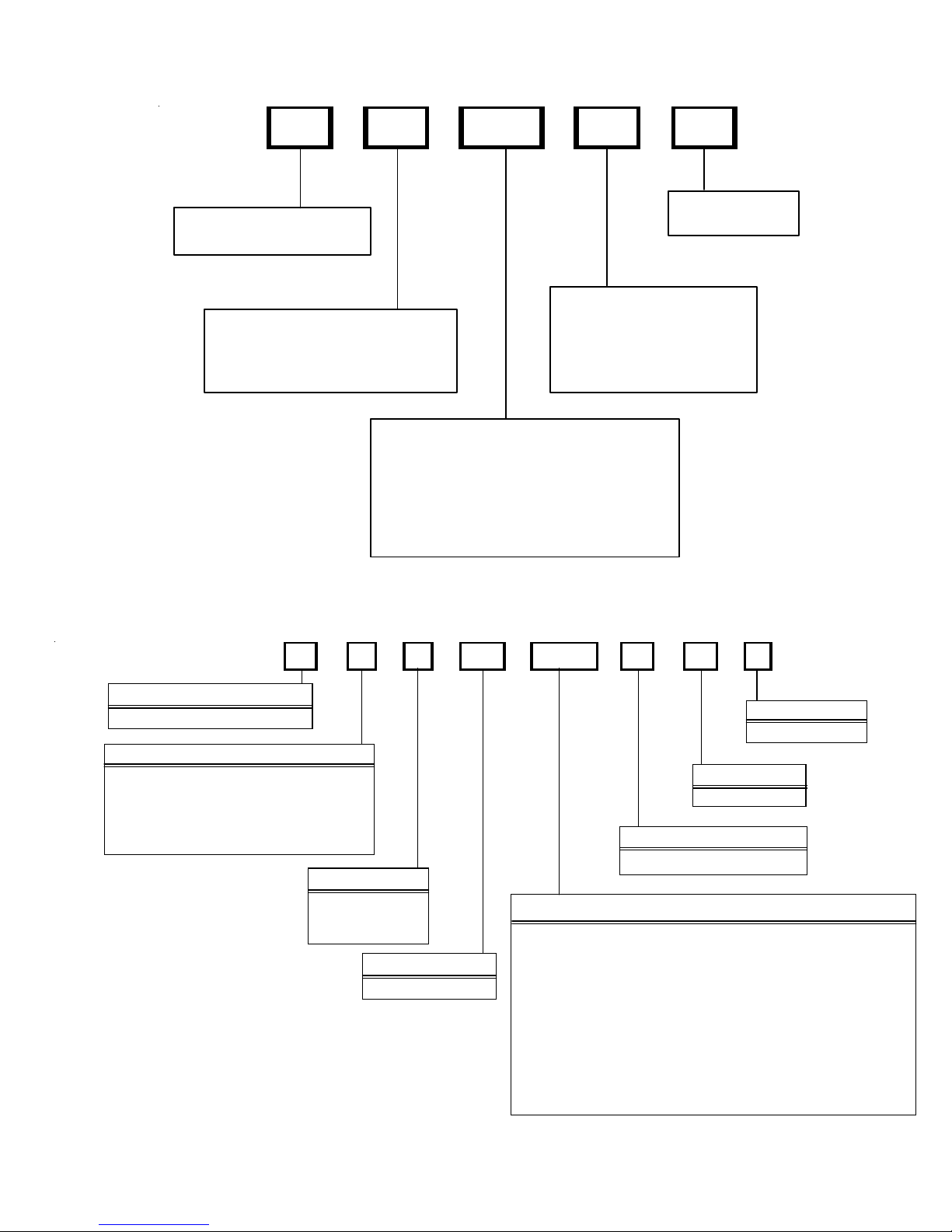
PRODUCT IDENTIFICATION
Split System Air Conditioners R-22
Model # Description
GSC13018-241AA
GSC13036-481AA
GSC1 303 6,48*AA
GSC130**1AB
GSC1 303 6,48*AB
GSC1 3048* AC
GSC13018- 30AC
GSC1301 8,24, 301AD
GS C1300421AC, 484AC
GS C1 3018 , 24, 301 A E
GSC130 48 1, 48 3 AE/A F
GSC130363AE/AF
GSC130361DE/DD
o odman® Br and Split Co ndenser 13 Seer condensi ng units . Init ial release . 26 " chassis
G
G
o odman® Br and Split Co ndenser 13 Seer condensi ng units . Init ial release . 29 " chassis
o odman® Br and Split Co ndenser 13 S eer co ndensing units.
G
Introduce s new 13 SEER AC 3 P H R- 22 Goodm an M odels
G
o odman® Br and Split Co ndenser 13 S eer co ndensing units. Move locat ion of screw
hole.
o odman® Br and Split Co ndenser 13 S eer co ndensing units. Int r oduces new models
G
due to the replacement of 8-pole fan motors with 6-pole.
G
o odman® Br and Split Co ndenser 13 S eer co ndensing units. Move locat ion of screw
hole.
o odman® Br and Split Co ndenser 13 S eer co ndensing units. Release M odels
G
contai ning the br oad oc ean motor 0131M00 06 0
G
o odman® Br and Split Co ndenser 13 S eer co ndensing units. Remo v e 1 hairpin from
coil.
o odman® Br and Split Co ndenser 13 S eer co ndensing units. Release Models contain
GSC1 3048* AD
GSC130481AG
GSC130181BA
GSC130361BA
GSC130361BA
GSC130361BB
GSC130361DF
GSC13024-301CA
GSC130241DA
GSC13036 1FA
GSC130363BA
GSC130301DA
G
the broad ocean motor 0131M 00061
G
o odman® Br and Split Co ndenser 13 S eer co ndensing units. Int r oduces new models
with Bristol compressors.
o odman® Br and Split Co ndenser 13 Seer condensi ng units . Co nver s ion of existin g
G
mod e ls us i ng 3/ 8" dia m e t er tube c oi ls t o 5 mm c o il s.
G
o odman® Br and Split Co ndenser 13 Seer condensi ng units . Init ial release . 35 "
chassis.
o odman® Br and Split Co ndenser 13 S eer co ndensing units. Release M odel wi th
G
Cop eland Scr oll Compressor .
G
o odman® Br and Split Co ndenser 13 S eer co ndensing units. Int r oduces new models
due to the replacement of 8-pole fan motors with 6-pole.
o odman® Br and Split Co ndenser 13 S eer co ndensing units. Int r oduces new models
G
with Bristol compressors.
G
o odman® Br and Split Co ndenser 13 S eer co ndensing units. Int r oduces mo dels wit h
reduced chas sis size from the cur rent 29x3 2.5 to 26x32
o odman® Br and Split Co ndenser 13 S eer co ndensing units. Release of Goodman 13
G
SEER Condensers, with 5 mm coils; compressor change:CR18K7-PFV-230; reduced
refrigerant charge.
o odman® Br and Split Co ndenser 13 Seer condensi ng units . Co nver t s from 3/ 8" to
G
5mm. 2.5 & 3 to n units hav e new coil sl ab height and ne w lo uv er panels . 2.5 - sma ll
chas s is; 3 ton medium chassis.
4
Page 7
PRODUCT IDENTIFICATION
Split System Air Conditioners R-22
M ode l # Des c ri ptio n
o odm an® Br and Split Condenser 14 Seer condensing units. Intr oduces Goodman®
GSC14 0**1AA
GSC14 0**1AB
GSC140**1AC
GSC140**1AD
GSC14018-421BA
G
Brand 1 4 Seer AC R-2 2 models.
G
o odm an® Br and Split Condenser 14 Seer condensing units. New rev isions hav e screw
locations m ov ed in the top pa nel, bas e pans, l ouv ers , an d c ont r ol b ox c ov er s .
o odm an® Br and Split Condenser 14 Seer condensing units. Relea se models
G
cont aining th e B ro ad Ocea n m otor 013 1 M00060 and 0131M000 61
G
o odm an® Br and Split Condenser 14 Seer condensing units. Revise c ondenser coils by
remov ing (1) hairpin. Reducing r efrigerant quanti ties by 6 ounces.
o odm an® Br and Split Condenser 14 Seer condensing units. Conver s ion of existing
G
models using 3/8" d iameter tube coils to 5 mm coils.
Split System Air Conditioners R-22
M ode l # Des c ri ptio n
A
ASC130**1AA
ASC130**1AB
ASC130**1AC
ASC1301**1AD
ASC130601BD
mana® Brand Split Condenser 13 Seer condensing units. Initial release new models of
Amana® Brand Deluxe 13 S eer AC R-22 c onditioners.
mana® Brand Split Condenser 13 Seer condensing units. Move location of screw hole.
A
A
mana® Brand Split Condenser 13 Seer condensing units. Introduces horizontal style
louvers.
mana® Br and Split Co ndenser 13 Se er condensing unit s . Re mo v e 1 hairpin fro m coil.
A
Sp ec ial Hi gh Fe atu re S p lit X Co nd en ser 14 See r conde ns in g uni t s.
hai rpin fr om coil. Reduce refrigerant quantities by 6 ounces.
Split System Air Conditioners R-22
M ode l # Des c ri ptio n
V
VSC13018-601AA
alue Split Condenser 13 Seer condensing units. Introduces Value 13 Seer AC R-22
models. 2 year part & 5 y ear com pressor warra nty in B ahama Bei ge.
. Remove 1
5
Page 8
PRODUCT IDENTIFICATION
Split System Heat Pumps R-22
M ode l # De sc r iption
GSH10***AA
GSH10***AB
GSH13***AA
GSH13**1AB
GSH13**1AC
GSH13036-48*AD
GSH13018-301BA
GSH130421AE
o odm an® Brand Sp lit Hea t Pum p 10 Se er heat pump units. Initial releas e.
G
o odm an® Brand Spl it Heat P um p 10 S eer heat pump unit s. S c rew location s
G
mov ed in th e to p panel, ba se pans, lo uv er s , and co ntrol box cov er s . .
o odm an® Brand Sp lit Hea t Pum p 13 Se er heat pump units. Initial releas e.
G
o odm an® Brand Spl it Heat P um p 13 S eer heat pump unit s. Revis ion
G
intr oduces the f ollowing new models due to the rep lacement of 8-pole fa n mo to r s
wi th 6-pole and screw locations mov ed in t he t op panel, bas e pans, l ouv ers , an d
control box covers.
o odm an® Brand Spl it Heat P um p 13 S eer heat pump unit s. Cont ain Broad
G
Oce an m otors S c re w locat ions moved in the top pane l, base pans, louvers, and
control box covers. .
G
o odm an® Brand Spl it Heat P um p 13 S eer heat pump unit s. I ntroduces m odels
that contain the broad ocean motor
o odm an® Brand Spl it Heat P um p 13 S eer heat pump unit s. Reducti on in
G
chass is size from medium to smal l.
o odm an® Brand Spl it Heat P um p 13 S eer heat pump unit s. Repl a ces V 10
G
rever s ing valve with V 6 r ev er sing v alve.
GSH13048*AG
GSH13036*BA/BB
GSH140**1AA
GSH140**1AB
GSH1 40* *1AC
GSH140361AF,
GSH140421-48AD
GSH140601AE
o odm an® Brand Spl it Heat P um p 13 S eer heat pump unit s. I ntroduces
G
model with Bristol Compressors.
G
o odm an® Brand Spl it Heat P um p 13 S eer heat pump unit s. I m pr ov ements to
increase MOP values on 3 ton units.
o odm an® Brand Spl it Heat P um p 14 S eer heat pump unit s. I nitial re lease.
G
G
o odm an® Brand Spl it Heat P um p 14 S eer heat pump unit s. S c rew location s
mov ed in th e to p panel, ba se pans, lo uv er s , and co ntrol box cov er s .
o odm an® Brand Spl it Heat P um p 14 S eer heat pump unit s. Releases
G
models wit h the Broad Ocean mot or .
G
o odm an® Brand Spl it Heat P um p 14 S eer heat pump unit s. Releases
models tha t replace TXV & co mp ens ato r with flowrator & ac cu mulator.
6
Page 9
PRODUCT IDENTIFICATION
Split System Heat Pump s R-22
Model # D e scr ip t ion
A
ASH130**1AA
ASH130**1AB
ASH130**1AC
Model # D e scr ip t ion
VSH13 18-601AA
mana® Bran d Split Heat Pump 13 Seer heat pump units. Initial release new
mode ls of Amana® Br and D e lux e 13 S eer R-22 heat pum ps .
mana® Bran d Split Heat Pump 13 Seer heat pump units. New revisions have
A
scr ew locations moved in the top panel, b ase pans, louvers, an d cont rol box
covers.
A
mana® Bran d Split Heat Pump 13 Seer heat pump units. New revisions have
horizon tal style louv ers.
Split System Heat Pump s R-22
V
alue Split He at Pump 13 Seer h eat pum p units . Introd uc es Value 13 Se er HP R-
22 mode ls. 2 year parts & 5 ye ar compressor wa rranty i n Bahama Beige.
7
Page 10
PRODUCT IDENTIFICATION
Single Piec e Air Ha ndl e r s
Model # Description
Singl e P i ec e R Multi-Position PSC Motor Unpainte d Flowrater Introduc t i on of new 13
ARUF****16AA
ARUF364216AB
ARUF486016AB
ARUF364216AC
ARUF****16BA
ARUF****1BA
A
SE E R A i r Handler Model s. All M odel s will be suitable for us e with R-22 and R-410A
Singl e P i ec e R Multi-Position PSC Motor Unpainte d Flowrater. Revision replac es the
A
current s pot wel ded blower hous i ng wit h the same cinched or cri m ped des i gn used on
the 80% furnace l i ne.
Singl e P i ec e R Multi-Position PSC Motor Unpainte d Flowrater. Revision replac es the
A
current s pot wel ded blower hous i ng wit h the same cinched or cri m ped des i gn used on
the 80% furnace l i ne.
Singl e P i ec e R Multi-Position PSC Motor Unpainte d Flowrater. Revision replac es the
A
current s pot wel ded blower hous i ng wit h the same cinched or cri m ped des i gn used on
the 80% furnace l i ne.
Singl e P i ec e R Multi-Position PSC Motor Unpainte d Flowrater. Revi s i on replaces all
A
ARUFc oi l s using wavy fin wit h l ouver enhanced fin.
Singl e P i ec e R Multi-Position PSC Motor Unpainte d Flowrater Introduc at i on of R-22
A
Only A i r Handlers .
ARPF****16AA
ARPF364216AB
ARPF486016AB
ARPF****16BA
ARPF****1BA
ADPF****16AA
ADPF364216AB
ADPF486016AB
Singl e P i ec e R Multi-Position PSC Motor Painted Flowrater Introduc at i on of new 13
A
SE E R A i r Handler Model s. All M odel s will be suitable for us e with R-22 and R-410A
Singl e P i ec e R Multi-Position PSC Motor Painted Flowrater. Revision replac es the
A
current s pot wel ded blower hous i ng wit h the same cinched or cri m ped des i gn used on
the 80% furnace l i ne.
Singl e P i ec e R Multi-Position PSC Motor Painted Flowrater. Revision replac es the
A
current s pot wel ded blower hous i ng wit h the same cinched or cri m ped des i gn used on
the 80% furnace l i ne.
Singl e P i ec e R Multi-Position PSC Motor Painted Flowrater. Revision replac es all
A
ARPF coils using wavy fin with louver enhanced fin.
Singl e P i ec e R Multi-Position PSC Motor Painted Flowrater. Introduc ation of R-22
A
Only A i r Handlers .
Singl e P i ec e Downflow PSC Mot or Unpainted Flowrater. Introduc at i on of new 13
A
SE E R A i r Handler Model s. All M odel s will be suitable for us e with R-22 and R-410A
Singl e P i ec e Downflow PSC Mot or Unpainted Flowrater. Revi s i on replaces the current
A
spot wel ded blower hous i ng wit h the same c i nched or crimped des i gn us ed on t he 80%
furnace line.
Singl e P i ec e Downflow PSC Mot or Unpainted Flowrater. Revi s i on replaces the current
A
spot wel ded blower hous i ng wit h the same c i nched or crimped des i gn us ed on t he 80%
furnace line.
Singl e P i ec e Downflow PSC Mot or Unpainted Flowrater. Revi s i on replaces the current
A
ADPF304216AC
ADPF****1BA
spot wel ded blower hous i ng wit h the same c i nched or crimped des i gn us ed on t he 80%
furnace line.
Singl e P i ec e Downflow PSC Mot or Unpainted Flowrater Revision replaces all
A
ARPF coils using wavy fin with louver enhanced fin.
8
Page 11
PRODUCT IDENTIFICATION
-
S ing le Pie ce Air Ha n dl ers
Mode l # Description
Single Piece E Mult i-P os ition Vari able-Speed Painted Flowrator. Introducation of
A
AEPF****16AA
AEPF****16BA
AEPF****16BB
AEPF****16CA
AEPF****1BA
new 13 SE E R Air Handler M odels. A ll M odels w il l be s uitable for us e wit h R- 22 and
R-410A
Single Piece E Mult i-P os ition Vari able-Speed Painted Flowrator. Revision
A
introduces new models add ing low er kw hit ki ts on the S &R plate
Single Piece E Mult i-P os ition Vari able-Speed Painted Flowrator. Revision
A
replaces t he c ur r ent spo t welded blower housing w ith t he same c inch ed o r crimped
design use d on the 80% fu r n ac e l i ne.
A
Single Piece E Mult i-P os ition Vari able-Speed Painted Flowrator. Revision
replaces all ARP Fcoils us i ng wavy fin w ith louver enhanc ed fin.
Single Piece E Mult i-P os ition Vari able-Speed Painted Flowr at or Intr o ducti o n of R
A
22 O nly Air Han dlers.
AEPF313716AA
ASPF313716AA
ASPF****16AA
ASPF****16BA
AWUF****1AA
AWUF****16AA
AWUF3005-101AA
AWUF****1BA
AWUF370**16AA
(ASPF)
(AEPF)
. Introduction of
A
Single Piece E Mult i-P os ition Vari able-Speed Painted Flowrator
Sin gle Piece S Mult i -Position EEM mo tor Painted Flowrator
3-Ton Air Handle r units wi th 3-row co i l.
Single Piece S Multi-Position EEM mot or Painted Flowrator. Introduces new
A
ASPF Air H andlers
Single Piece S Multi-Position EEM mot or Painted Flowrator. Revision introuces
A
modi fied ASPF control scheme, to ensur e blower operation duri ng and after call for
hea t on units wi th heat k it s and r eplacing wav y fi n with louver enhance d fin on coi l
Single Piece Ai r Handler Wal l Mount Unpainted Flo wrator. Introduc es 13 SEER
A
Dayto n wall mount air ha ndlers
Single Piece Ai r Handler Wal l Mount Unpainted Flo wrator. Introduc es 13 SEER
A
Dayton wall mount air handlers. All Models will be suitable for use with R-22 and R410A
Single Piece Ai r Handler Wal l Mount Unpainted Flo wrator. Introduc es 13 SEER
A
Dayton wall moun t air handlers using a Burr Oak Louvered Fin coil.
A
Single Piece Ai r Handler Wal l Mount Unpainted Flowrat o r . Revision replace s
cur r ent wavey fin design wit h new louv ered fin design
Single Piece Ai r Handler Wal l Mount Unpainted Flowrator. Introduction of
A
AWUF37 Air Handl er s for use wit h R- 22 and R410A .
and
A
AWUF****16BA
ACNF****1AA
ACNF****16 AA
ACNF****1BA
AH**-1*
Single Piece Ai r Handler Ceiling Mount N Un ca s ed Flow rater. Rev ision has
A
louv er fins & replaces copper tu be hairpi ns with aluminum hairpins.
A
Single Piece Ai r Handler Ceiling Mount N Un ca s ed Flow rater. Rev ision re lease
all models of 13 SEE R Dayt on u n c ase d ai r handler s.
Single Piece Ai r Handler Ceiling Mount N Un ca s ed Flow rater. Rev ision re lease
A
all models of 13 SEER Dayton u n c as ed air handlers.All M odels w ill be s uitable for
use with R-22 and R-410A
Single Piece Ai r Handler Ceiling Mount N Un ca s ed Flow rater. Rev ision repla c es
A
cur r ent wavey fin design wit h new louv ered fin design
A
Single Piece Ai r Handler Hydronic Air Hand ler. Revision replaces the time dela y
r e lay in the AH a i r ha ndl ers w i th the UTE C t ime del ay co ntr ol bo ard.
9
Page 12
PRODUCT IDENTIFICATION
A
MBR/MBE Air Handlers
Mo del # Description
odular Blower R Multi- P os iti on P S C M otor. Introduc es module blo wer wit h P S C
MBR****AA-1AA
MBE****AA-1AA
MBE****AA-1BA
Mo del # Description
CAUF*****6AA
CAUF*****6BA
M
b l ower m o t o r .
M
odular Blower E Multi- Pos ition Variable-Speed . I ntrodu c es module blower wit h
variable speed blo wer m ot or .
odular Blower E Multi- Pos ition Variabl e- S peed .Revision in troduces new m odels
M
adding lower kw hit kits on the S&R plate
Evaporator Coils
C
Indoor Coil A Upfl ow/Downflow Uncased Flowrator. In troduces 13 SEER CAUF
Dayton Upflow/Downflow coils.
Indoor Coil A Upfl ow/Downflow Uncased Flo wrator. Revision releases Burr Oak
C
Lou v er ed F in in pl ac e of th e Wavy Fin current ly in pr oducti on.
CAPF*****6AA
CAPF*****6BA
CAPF/CAUF36***CA
CHPF*****6AA
CHPF*****6BA
CHPF1824A6CA
CHPF2430B6CA
CHPF3636B6CA
CHPF3642C6CA
CHPF3642D6CA
CHPF3743C6BA
CHPF3743D6BA
CHPF4860D6D
CSCF*****6AA
Indoor Coil A Upfl ow/Downflow Painted Flowrator. Introduces 13 SEER CAPF
C
Dayton Upflow/Downflow coils.
C
Indoor Coil A Upfl ow/Downflow Painted Flow rator. Rev ision releases Burr Oa k
Lou v er ed F in in pl ac e of th e Wavy Fin current ly in produ c tion.
Indoor Coil A Upfl ow/Downflow [Painted or Uncased] Flowrator. Revision
C
redesigns for pe rfor m ance impr ovement from 2 row to 3 row.
C
Indoor Coil Horizontal A Coil Painte d Flowrator. Release 13 SEER CHPF
horizon tal A coil.
C
Indoor Coil Horizontal A Coil Painte d Flowrator. Release 13 SEER CHPF
horizon tal A coil. Rev is ion rele as es Bur r O ak Louvered Fin in place of the Wavy
Fin c ur rently in product ion. T he rows chang e by one, (i . e. 4 r ow to 3 row; 3 row t o
2 row) where appl ic able.
Indoor Coil Horizontal A Coil Painte d Fl owr ato r . 13 S EER CHPF hor izontal A
C
coil, revision has louver fins & replaces copper tu be hairpins with a luminum
hairpins.
Indoor Coil S Horizontal Slab Coil C Upainted Flowrator. Release 13 SEER
C
CSCF slab hor izontal coil.
Indoor Coil S Horizontal Slab Coil C Upainted Flow rator. Revi sion r eleases Bur r
C
CSCF*****6BA
10
Oak Louvered Fin in place of the Wavy Fin currently in production. The rows
change by one, ( i. e. 4 row to 3 r ow; 3 r ow t o 2 r ow) where app lic able .
Page 13
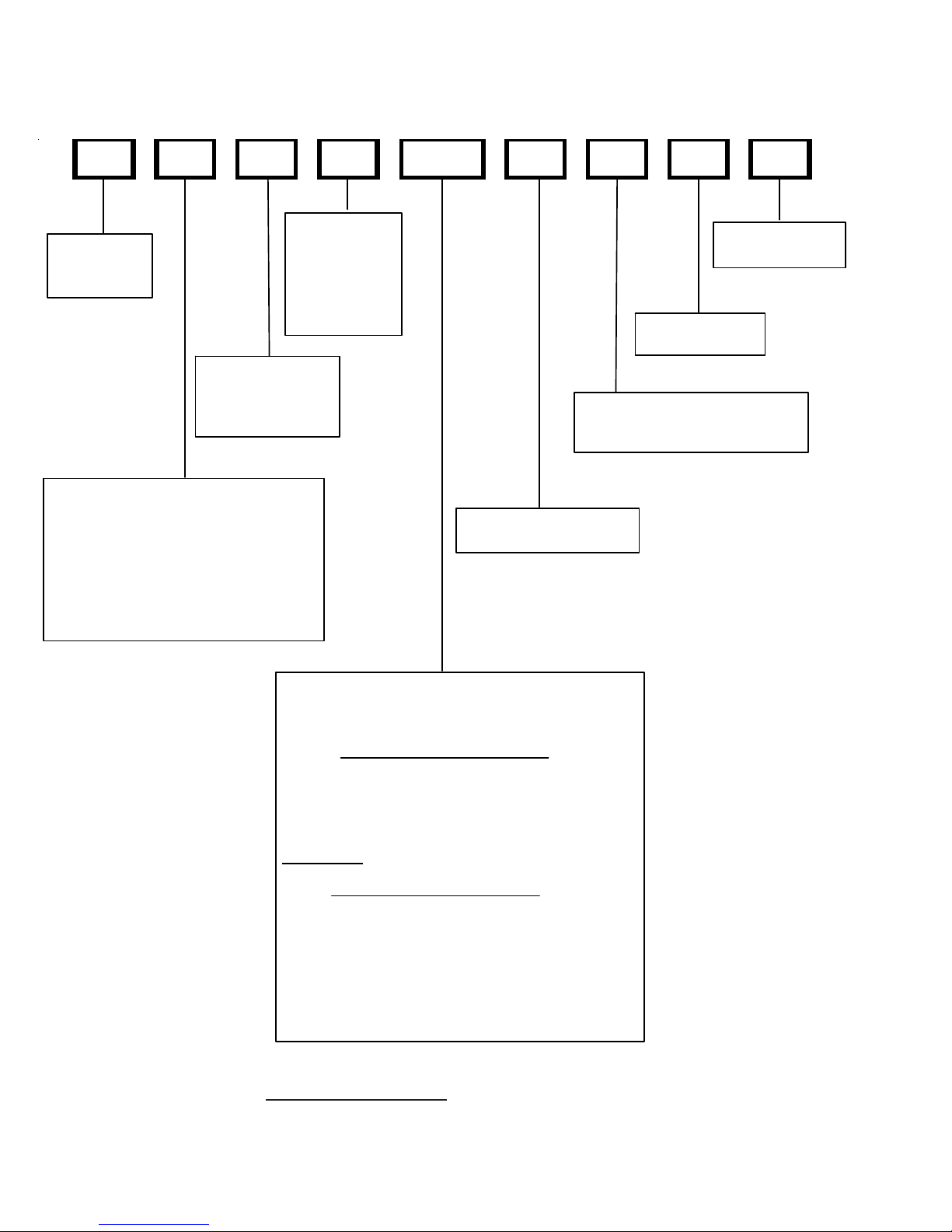
PRODUCT IDENTIFICATION
p
GSC140361AA
BR A ND:
G: Goodm a n
Amana
A: Amana
V: Val ue
®
®
Brand Dist inctio ns
®
Brand
Brand /
PRODU CT
CATE GORY:
S: Split System
UNIT TYPE:
C: Condense r R-22
H: Heat Pum p R-22
SEER:
10 : 10 SE E R
13 : 13 SE E R
14 : 14 SE E R
NOMINAL
CA PACITY :
018: 1.5 Tons
024: 2 Tons
030: 2.5 Tons
036: 3 Tons
042: 3.5 Tons
048: 4 Tons
060: 5 Tons
MINOR
REVIS ION:
A: Initial Releas e
MAJOR
REVISION:
A: I n itial Re lea s e
ELEC TRICAL:
1: 208-230V/1ph/60H z
3: 208-230v/3ph/60H z
4: 460v/3ph/60H z
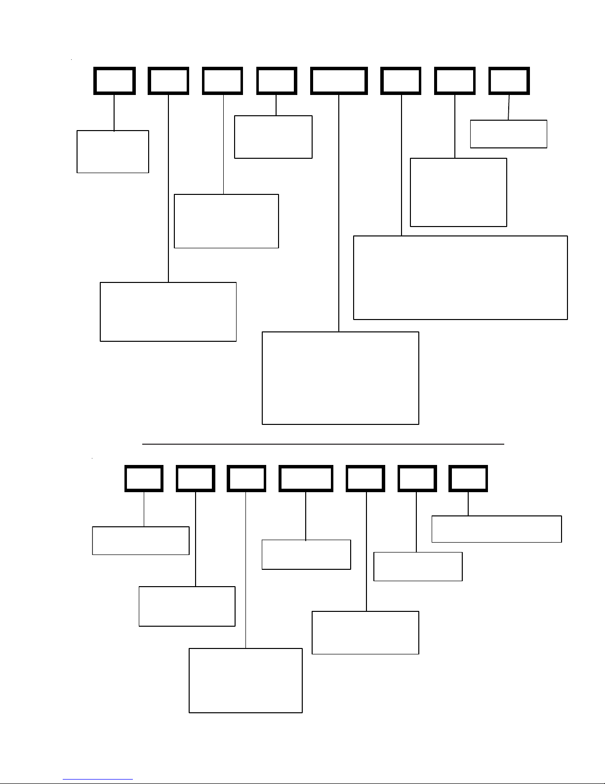
CPKF036 2 A
PROD UCT CATE GOR Y :
C : Split System
UNIT TYPE:
E: Commercial Air Con ditioner
K: Air Cojd itioner
P: Heat Pum
REVISION:
A: Re vision
ELECT RICAL:
1: 208- 230V/1ph/60Hz
2: 220- 240V/1ph/50 Hz
3: 208-23 0v /3ph/60 Hz
4: 308/415V /3 ph/ 50Hz
NOMINAL CAPACITY:
018: 1 .5 Ton s 048: 4 Tons
024: 2 Tons 060: 5 Tons
030: 2 .5 Ton s 070: 5 Tons
036: 3 Tons 090: 7.5 T ons
042: 3 .5 Ton s 120: 1 0 Tons
11
Page 14
PRODUCT IDENTIFICATION
p
p
C KF 036 2 A
P R O D UCT CATEGORY :
C : Split Sy s tem
UNIT TYPE:
E: Co m mercial Air Conditioner
K: Air Cojditioner
P: Heat Pum
NOMINAL CAPACITY:
018: 1.5 T ons 048: 4 Tons
024: 2 Tons 060: 5 Tons
030: 2.5 T ons 070: 5 Tons
036: 3 Tons 090: 7.5 T ons
042: 3.5 T ons 120: 1 0 Tons
REVISION:
A: Re vision
ELECTRICAL:
1: 20 8- 230V/1ph/60Hz
2: 22 0- 240V/1ph/50 Hz
3: 20 8- 230v/3ph/60Hz
4: 30 8/415V/3 ph/50Hz
CKL0362A
PRODUC T CATE GO R Y :
C : Split Sys tem
UNIT TYPE:
E: Commercial Air Conditione r
K: Air Cojditioner
P: Heat Pum
REVISION:
A: Revi sion
ELECTRICAL:
1: 20 8-23 0V /1ph/60 Hz
2: 22 0-24 0V /1ph/5 0 Hz
3: 20 8-23 0v /3ph/60 Hz
4: 308/415V/3ph/50Hz
NOMINAL CAP ACITY:
018: 1.5 Tons 04 8: 4 Tons
024: 2 Tons 060: 5 Tons
030: 2.5 Tons 07 0: 5 Tons
036: 3 Tons 090: 7.5 Tons
042: 3.5 Tons 120: 10 Tons
12
Page 15
PRODUCT IDENTIFICATION
A
A
A
A
A
A
p
C E 120 5 A
PRODUCT CATEGOR Y:
C : Split Syst em
UNIT TYPE:
E: Comm ercial Air Conditioner
K: Air Cojdit ioner
P: Heat Pum
N OMINA L CAPACI TY:
018: 1.5 Tons 048: 4 Tons
024: 2 Tons 060: 5 Tons
030: 2.5 Tons 070: 5 Tons
036: 3 Tons 090: 7.5 Tons
042: 3.5 Tons 120: 10 Tons
REVISION :
A: Revision
ELECTRICAL:
1: 208-230V/1ph/60Hz
2: 220-240V/1ph/50 Hz
3: 208-230v/3ph/60Hz
4: 308/ 415V /3ph /50Hz
THIS NOMENCLATURE IS TO BE USED TRHOUGH JULY 2006
R U F 3642 1
Product Type
: Single Piece Air Handler
Application
C: Ceiling Mo un t P S C Mo to r
D: Downflow PSC Motor
E: Multi-Position Variable Speed Motor
R: Multi-Position PSC Motor
W: Wall Mount PSC Motor
Cabinet Finish
U: Unpainted
P: Painted
N: Uncased
Expansion Device
F: Flowrater
Nominal Capacity Range @ 13 SEER
Multi-Position & Downflow Applications
3642: 3 - 3 1/2 tons
1830: 1 1/2 - 3 1/2 tons
1729: 1 1/2 - 2 1/2 Tons 10 SEER (for export systems)
Ceiling Mount & Wall Mount Applications
1805: Nominal Cool ing Capacity
Electric Heat kw - 1 1/2 tons Cooling/5 kw Electric Heat
2405: Nominal Cool ing Capacity
Electric Heat kw - 2 Tons Cooling/5 kw Electric Heat
3608: Nominal Cool ing Capacity
Electric Heat kw - 3 Tons Cooling/8 kw Electric Heat
Minor Revisi on
: Initial Release
Major Revision
: Initial Release
Electrical
1: 208/230V, 1 Phase, 60 Hz
13
Page 16
PRODUCT IDENTIFICATION
THIS NOMENCLATURE IS TO BE USED AFTER JULY 2006
A W U F 3642 1 6 A A
EXP ANSION
PRODUCT
TYPE:
A: Air Han dler
CABINE T FINISH:
U: U npainted
P: Pa ited
N: Uncased
APPLICATION
C: Ceiling Mount PSC M otor
D: Downflow PSC Motor
E: Mul ti-Position Varible-Speed Motor
S: Energy-Efficient Mo tor
R: Multi-Position PSC Motor
T: Coated Coils
W: Wall M o unt PS C Motor
DEVICE:
F: Flowrater
T: TXV
(Expansion
Device)
MINOR
R EVISION*
MAJOR
REVISION*
R EFRIG ERANT C H ARG E:
No Digit: R-22 Only
6 : R-410A or R-22
ELECTRICA L:
1: 208-230V/1ph/60Hz
NOMINA L CAPA CITY RANGE:
@ 13 SEER
Dedicat ed Application
36 36: 3 T o ns
Multi-Posit ion & Dow nfl ow A ppli cations
31 37: 3 T o ns
3642: 3 - 3 1/2 Tons
1830: 1 1/2 - 3 1/2 Tons
@10 S E E R
1729: 1 1/2 - 2 1/2 Tons (for expo r t sys tems)
Ceiling Mount & Wall Mount Applications
(Nominal Cooling Capacity/Ele c tric Heat kW)
1805: 1 1/2 Tons Cooling / 5 kW Electric Heat
2 4 05: 2 Tons Co o lin g / 5 k W Ele ctr i c He at
3 6 08: 3 Tons Co o lin g / 8 k W Ele ctr i c He at
3 7 05: 3 Tons Co o lin g / 5 k W Ele ctr i c He at
3 7 08: 3 Tons Co o lin g / 8 k W Ele ctr i c He at
All Airhandlers use DIRECT DRIVE MOTORS. Power supply is AC 208-230v, 60 hz, 1 phase.
14
Page 17
PRODUCT IDENTIFICATION
r
C A P F 1824 A 6 A
PRODUCT
TYPE:
C: Indoor Coil
A PPLICATION
A: U pfl ow /Downflo w Coil
H: Horizontal A Coil
S: Horizontal Slab Coil
EXPANSION
DEVICE:
F: Flowrate
CAB INE T FINIS H:
U: Unpai n t ed
P: Pai nted
N: Unp ainted Case
REVISION
A: Revision
REFRIGERANT
CHARGE:
6: R-410A or R-22
2: R- 22
4: R- 41 0a
NOMINAL WIDT H FOR GAS F URNAC E
A : Fits 14" Furnace Cabinet
B: Fits 17 1/2" Furnace Cabinet
C: Fits 21" Fu r nac e C abi ne t
D: Fits 24 1/2" Furnace Cabinet
N: Does Not Apply ( Hor izontal Slab Coils)
NOMINAL CAPACITY RANGE
@ 13 SEER
18 24 : 1 1/2 to 2 T on s
30 30 : 2 1/2 To ns
36 36 : 3 Ton s
3642: 3 to 3 1/2 T ons
48 60 : 4 & 5 Ton s
MB R 8 00 A A 1
DESIGN SERIES:
MB: Modular Blower
MOTOR TYPE:
R: Consta nt Speed
E: Variable Speed
FACTORY HE AT
0 0: No Heat
AIRFLOW DE LI V E RE D
08: 800 CFM
12: 1200 CFM
16: 1600 CFM
20: 2000 CFM
ELECTRI CA L SUPPLY:
1 : 208-23 0V /60hZ/1 ph
DESIGN SERI ES
A: First Series
CIRCUIT BREAKER
A : No Cir c uit B r eak er
B: C irc uit B rea k er
MODEL MFG. #
MBR0800 MBR0800
MBR1200 MBR1200
MBR1600 MBR1600
MBR2000 MBR2000
MBE1200 MBE1200
MBE1600 MBE1600
MBE2000 MBE2000
15
Page 18
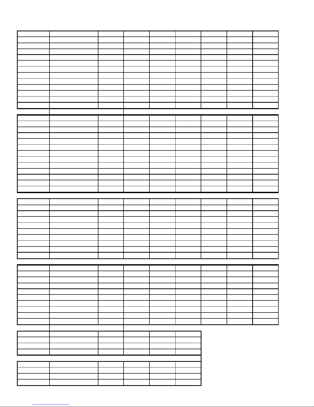
ACCESSORIES
X X X
X X
X X
t
X X X
X X
X X X
t
X X
A
t
X X X
X X
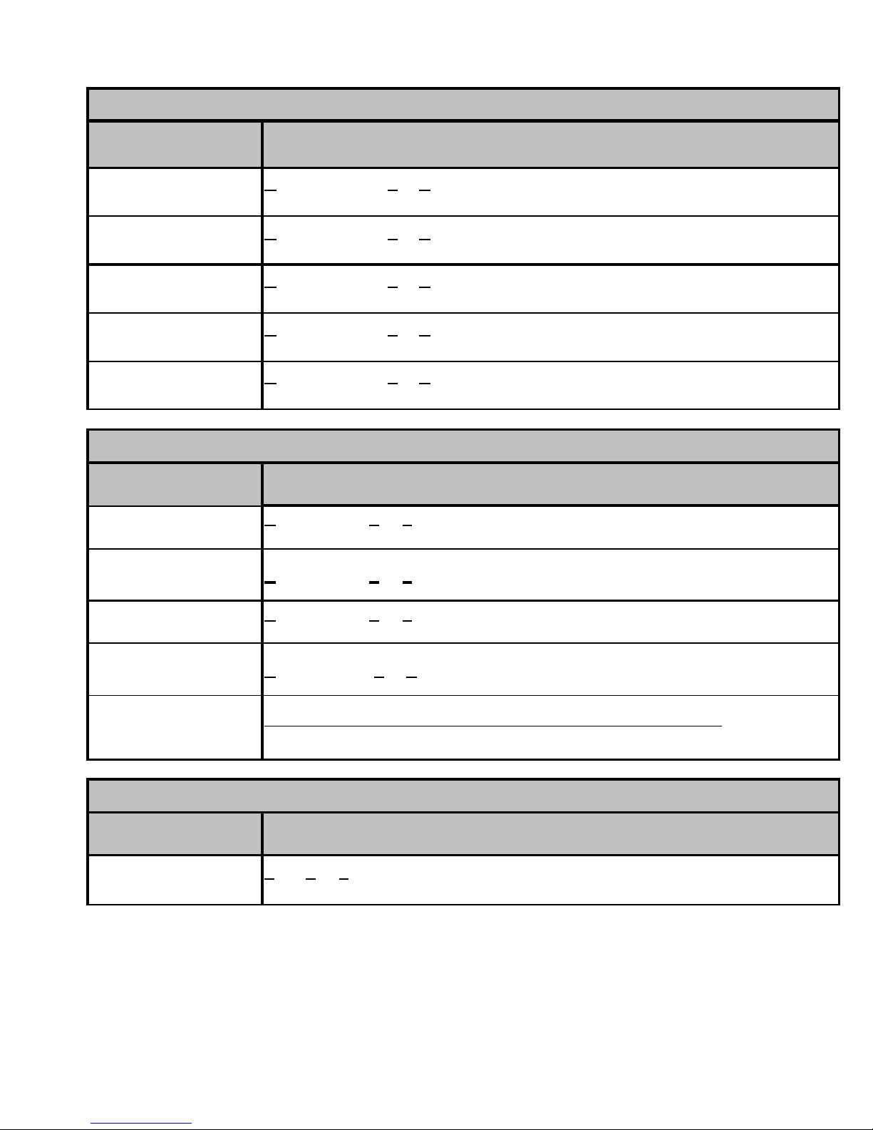
Mo del
AFE18-60A
OT18-60A
FSK01A*
ASC01
TX2N2*
TX3N2*
TX5N2*
OT18-60A
OT/EHR18-60
CSR-U-1
CSR-U-2
CSR-U-3
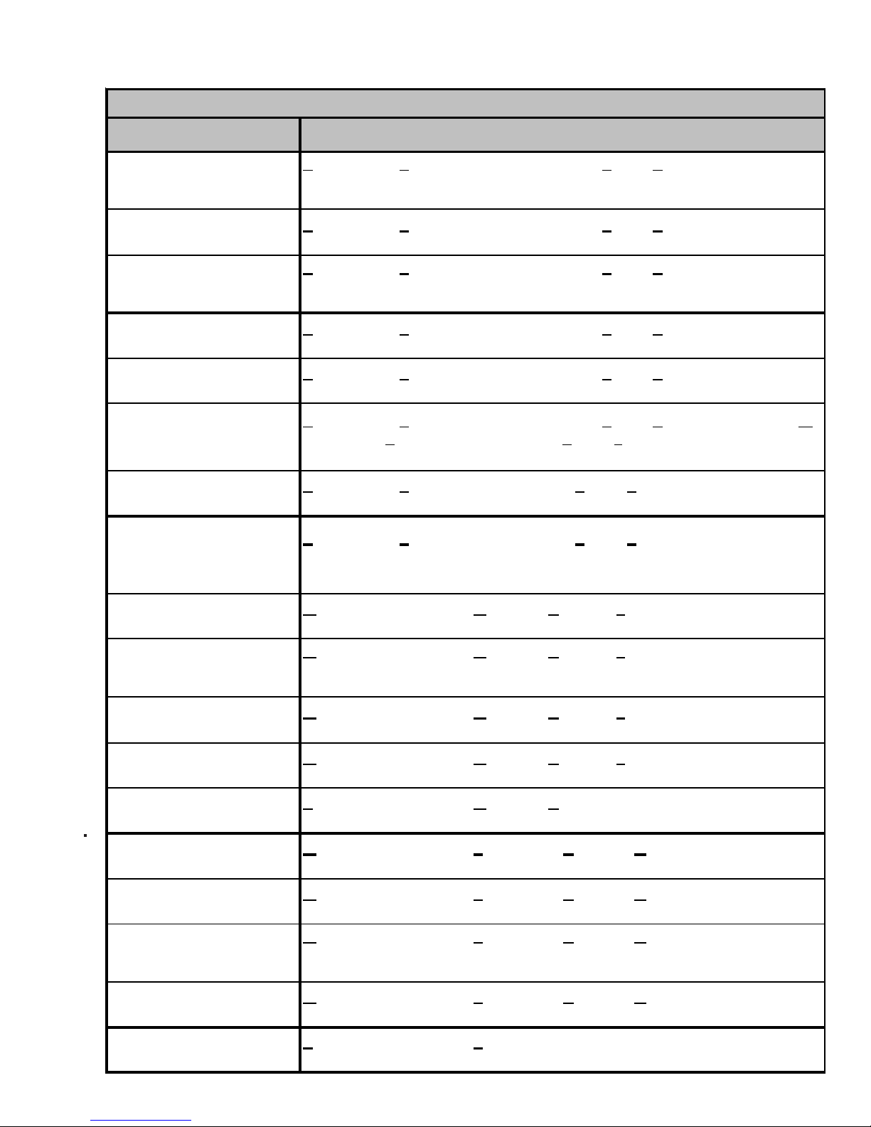
Descript ion G/ VSH13018 G /VSH13024 G/VSH 1 3030 G /VSH 13 036 G/VSH13042 G/VSH13048 G/VSH13060
All Fuel Kit
Outdoor Thermostat
Freeze Pr ote ct ion Ki t
Anti Short Cycle Kit
TXV Kit
TXV Kit
TXV Kit
Outdoor Lockout Stat
Emer ge ncy H eat relay kit
Hard Start Kit
Hard Start Kit
Hard Start Kit
X
X
X
X
X
X
X
X
X
X
X
X
X
X
X
X
X
X
X
x --- --- --- --- --- --x X
X
--- --- --- ---
X
X
X
X
X
X
X
X
X
--- --- ---
--- --- --- --- ---
X
X
X
X
X
--- --- ---
X
X
X
X
X
X
--- --- ---
X
X
X
X
X
X
X
X
X
X
Mo del
AFE18-60A
OT18-60A
FSK01A*
ASC01
TX2N2*
TX3N2*
TX5N2*
OT18-60A
OT/EHR18-60
CSR-U-1
CSR-U-2
CSR-U-3
Model
OT18-60A
FSK01A*
ASC01
TX2N2*
TX3N2*
TX5N2*
CSR-U-1
CSR-U-2
CSR-U-3
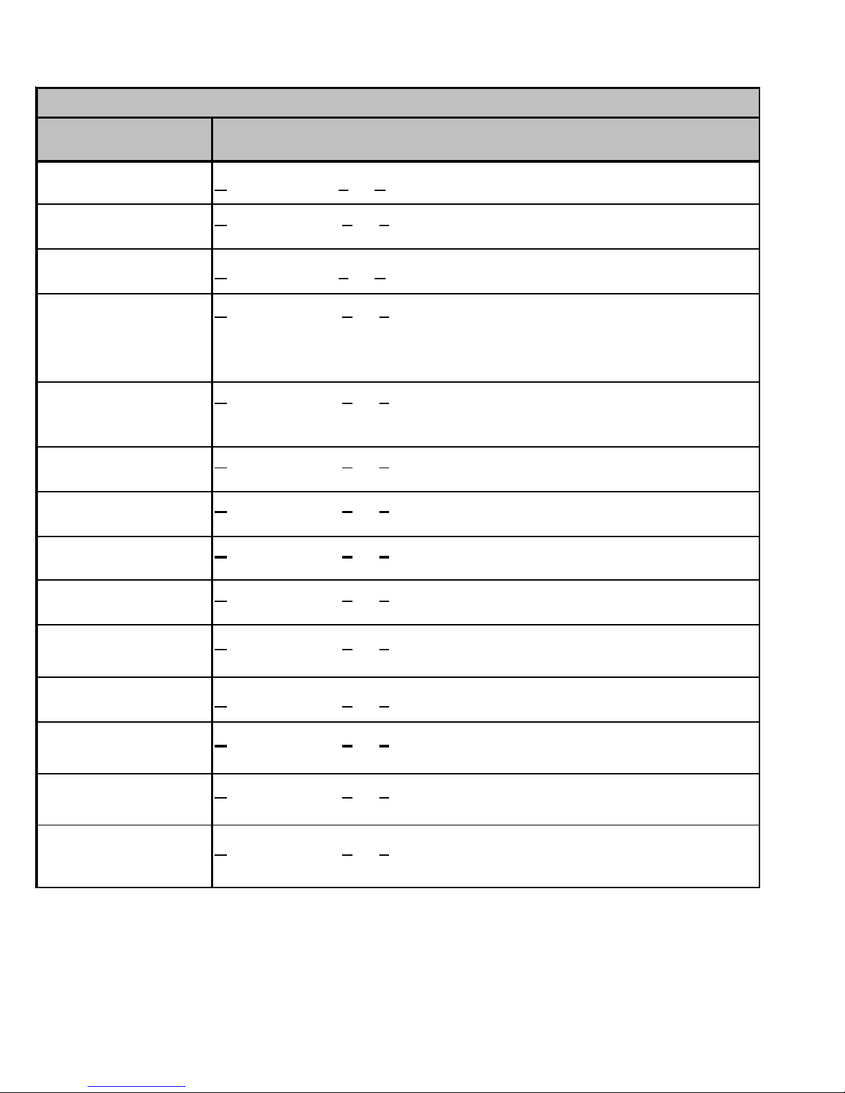
Descr iption A SH13018 ASH1 3024 ASH13030 ASH13036 AS H13042 A SH 13048 ASH13060
All Fuel Kit
Outdoor Thermosta
Freeze Pr ote ct ion Ki t
Anti Short Cycle Kit
TXV Kit
TXV Kit
TXV Kit
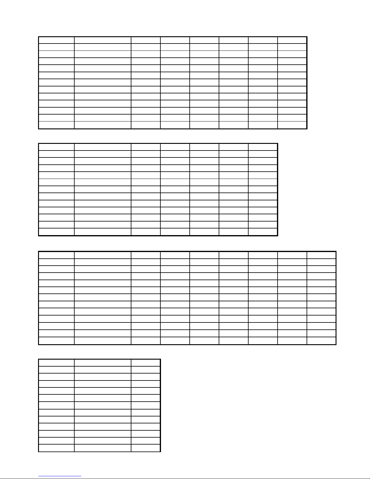
Outdoor Lockout Stat
Emer ge ncy H eat relay kit
Hard Start Kit
Hard Start Kit
Hard Start Kit
Description ASC 13018 ASC13024 ASC13030 ASC13036 ASC13042 AS C 13 048 ASC13060
Outdoor Thermosta
Freeze Pr ote ct ion Ki t
Anti Short Cycle Kit
TXV Kit
TXV Kit
TXV Kit
Hard Start Kit
Hard Start Kit
Hard Start Kit
X
X
X
X
X
X
X
X
X
X
X
X
X
X
X
X
X
X
X
x --- --- --- --- --- --x X
X
--- --- --- ---
X
X
X
X
X
X
--- --- ---
--- --- --- --- ---
X
X
X
X
X
--- --- ---
X
X
X
X
X
X
--- --- ---
X
X
X
--- --- --- --- --- --- ---
X
X
X
X
X
X
X
X
X
X
X
X
X
--- --- --- --- --- ---
x x x x --- --- ---
--- --- --- ---
X
--- --- ---
X
X
X
X
--- --- ---
--- --- --- --- ---
X
X
X
X
X
X
X
X
X
X
X
X
X
X
X
X
X
Model
OT18-60A
FSK01A*
ASC01
TX2N2*
TX3N2*
TX5N2*
CSR-U-1
CSR-U-2
CSR-U-3
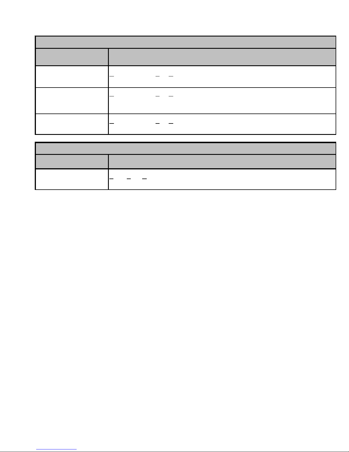
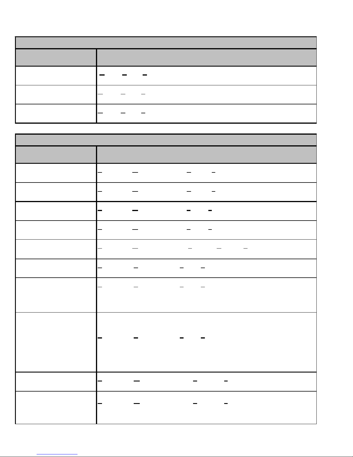
Model Description GSC100903 GSC100904 GSC101203 GSC101204
FSK01A*
ASC01
OT/EHR18-60
Model Description GSH100903 GSH100904 GSH101203 GSH101204
FSK01A*
ASC01
OT/EHR18-60
Descript ion G/ VSC13018 G /VSC13024 G/VSC 1 3030 G /VSC 13 036 G/VSC13042 G/VSC13048 G/VSC13060
Outdoor Thermostat
Freeze Pr ote ct ion Ki t
nti Short Cycle Ki
TXV Kit
TXV Kit
TXV Kit
Hard Start Kit
Hard Start Kit
Hard Start Kit
Freeze Pr ote ct ion Ki t
Anti Short Cycle Kit
Emer ge ncy H eat relay kit
Freeze Pr ote ct ion Ki t
Anti Short Cycle Kit
Emer ge ncy H eat relay kit
16
--- --- --- --- --- --- ---
X
X
X
X
X
X
X
X
--- --- --- --- --- ---
x x x x --- --- ---
--- --- --- ---
X
--- --- ---
X
X
X
X
--- --- ---
--- --- --- --- ---
X
X
X
X
X
xxxx
xxxx
--- --- --- ---
*Installed on indoor coil.
xxxx
xxxx
--- --- --- ---
X
X
X
X
X
Page 19
ACCESSORIES
Model
AFE18-60A
OT18-60A
FSK01A*
ASC01
TX2N2*
TX3N2*
TX5N2*
OT18-60A Outdoor Lockout Stat
OT/EHR18-60
CSR-U-1 Hard Start Kit
CSR-U-2
CSR-U-3 Hard Start Kit
Description
All Fuel Kit
Outdoor Thermostat
Freeze Protection Kit
Anti Short Cycle Kit
TXV Kit
TXV Kit
TXV Kit
Emergency Heat relay kit
Hard Start Kit
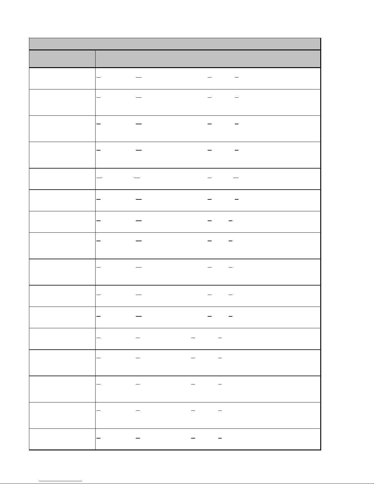
CPKF24 CPKF36 CPKF42 CPKF48 CPKF60 CPKF61
xxxxxx
xxxxxx
xxxxxx
xxxxxx
--- --- --- --- --- --x x --- --- --- ---
--- ---
xxxx
xxxxxx
xxxxxx
x x --- --- --- ---
---xxxxx
--- --- --- x x x
Model
AFE18-60A
OT18-60A
FSK01A* Freeze Protection Kit
ASC01
TX2N2*
TX3N2*
TX5N2*
OT18-60A
OT/EHR18-60
CSR-U-1
CSR-U-2
CSR-U-3
Model
AFE18-60A
OT18-60A
FSK01A*
ASC01
TX2N2*
TX3N2*
TX5N2*
OT18-60A
OT/EHR18-60
CSR-U-1
CSR-U-2
CSR-U-3
Description
All Fuel Kit
Outdoor Thermostat
Anti Short Cycle Kit
TXV Kit
TXV Kit
TXV Kit
Outdoor Lockout Stat
Emergency Heat relay kit
Hard Start Kit
Hard Start Kit
Hard Start Kit
Description
All Fuel Kit
Outdoor Thermostat
Freeze Protection Kit
Anti Short Cycle Kit
TXV Kit
TXV Kit
TXV Kit
Outdoor Lockout Stat
Emergency Heat relay kit
Hard Start Kit
Hard Start Kit
Hard Start Kit
CKF24 CKF36 CKF48 CKF60 CKF70
--- --- --- --- ---
--- --- --- --- --xxxxx
xxxxx
--- --- --- --- --x x --- --- ---
--- ---
xx
---
--- --- --- --- ---
--- --- --- --- --x x --- --- ---
--- x x x ---
--- --- x x ---
CKL18 CKL24 CKL30 CKL36 CKL42 CKL49 CKL60
--- --- --- --- --- --- ---
--- --- --- --- --- --- --xxxxxxx
xxxxxxx
x --- --- --- --- --- --xxxx---------
--- --- --- --- x x x
--- --- --- --- --- --- ---
--- --- --- --- --- --- --xxxx---------
--- --- --- x x x x
--- --- --- --- --- x x
Model
AFE18-60A
OT18-60A
FSK01A*
ASC01
TX2N2*
TX3N2*
TX5N2*
OT18-60A
OT/EHR18-60
CSR-U-1
CSR-U-2
CSR-U-3
Description
All Fuel Kit
Outdoor Thermostat
Freeze Protection Kit
Anti Short Cycle Kit
TXV Kit
TXV Kit
TXV Kit
Outdoor Lockout Stat
Emergency Heat relay kit
Hard Start Kit
Hard Start Kit
Hard Start Kit
CE120
---
--x
x
---
---
---
---
---
---
---
---
17
Page 20
ACCESSORIES
A
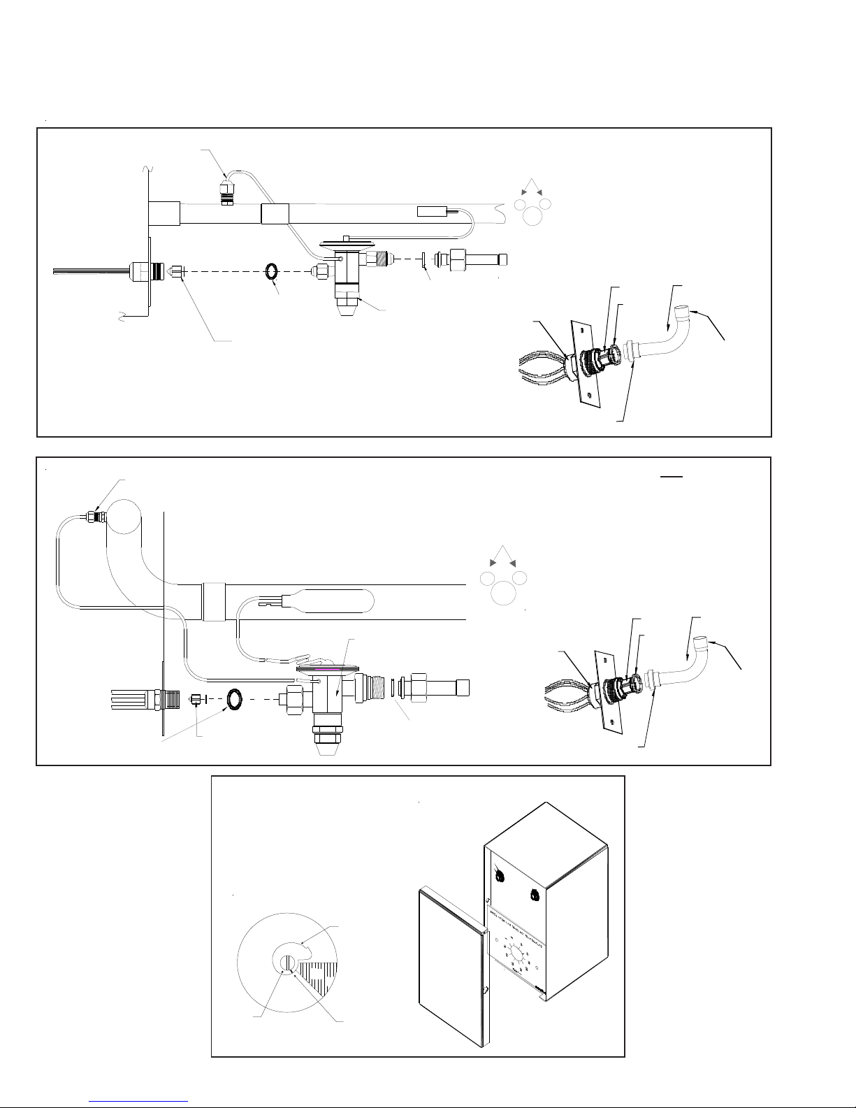
EXP ANSION VALVE KITS
1/4 FLARE CONNECTION
BULB TO BE LOCATED
AT 10 OR 2 O'CLOCK
For Applications requiring
a field installed access fitting
EVAPORATOR COIL
EVAPORATOR COIL
1/4' FLARE
CONNECTION
SEAL SUPP L IE D W/ KIT
REMOVE BEFORE INSTALLI NG EXP ANS IO N VALVE
SUCTION LINE
BULB
EXPANSION VALVE
SUCTION LINE
EXPAN SION VALVE
BULB
SEAL SUPPLIED W/ KIT
BULB TO BE LOCATED
AT 10 OR 2 O'CLOCK
DISTRIBUTOR
BODY
For Applications not requiring
a field installed access fitting
DISTRIBUTOR
BODY
7/8" NUT
PISTON
SEAL
PISTON
SEAL
TAILPIECE
3/8"SWEAT
TAILPIECE
3/8"SWEAT
REMOVE BEFORE
SEAL SUPPLIED W/ KIT
INSTALLING
EXPANSION VALVE
OUTDOOR THERMOSTAT &
EMERGENCY HEAT RELAY
315º
Set Point
djustmen t
Screw
18
SEAL SUPPLIED W/ KIT
OT/EHR18-60
OT18-60
Thermostat
Dial
(Turn Clockwise)
COLD
DEAD
DIAL
45º
WARM
Set Point
Indicato r
Mark
(Shown @ Oº F)
(Turn Counterclockwise)
7/8" NUT
Page 21
ACCESSORIES
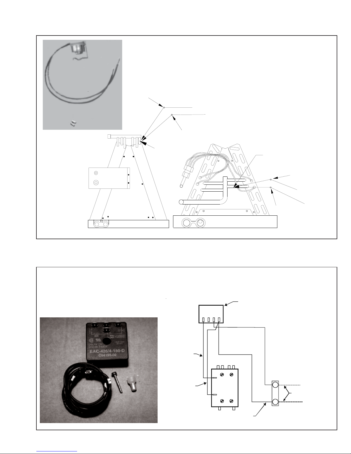
Y
Wire Nut
FSK01A
FREEZE THERMOSTAT
KIT
Y
k
c
a
l
B
k
c
a
l
B
Wire Nut
Y
Install L ine
Thermostat
Here
ASC01A
ANTI-SHORT -CYCLE CONTROL KIT
Y1Y2R1
R2
Install Line
Thermostat
Wire Nut
SHOR T CYCLE
PROTECTOR
Here
B
l
a
c
k
B
l
a
c
Wire Nut
Y
k
Y
ELLOW 1
BLACK 1
CONTACTOR
T2 T1
L2
L1
BLACK 1
Y
THERMOSTAT
WIRE
C
UNIT
TERMINAL
BOARD
19
Page 22
ACCESSORIES
COIL MODEL TX2N2 TXV KIT TX3N2 TXV KIT TX5N2 TXV KIT FSK01A FREEZE PROTECTION KIT
CA*F030B4* --- X --- X
CA*F036B4* --- X --- X
CA*F042C4* --- --- X X
CA*F048C4* --- --- X X
CA*F057D4* --- --- X X
CA*F060D4* --- --- X X
CHPF030A4* --- X --- X
CHPF036B4* --- X --- X
CHPF042A4* --- --- X X
CHPF048D4* --- --- X X
CHPF060D4* --- --- X X
CH36FCB --- X --- X
CH48FCB --- --- X X
CH60FCB --- --- X X
CA*F18246* X X --- X
CA*F30306* --- X --- X
CA*F36426* --- X X X
CHPF18246* X --- X X
CHPF30306* --- --- X X
CHPF36426* --- --- X X
CSCF1824N6* X --- --- X
CSCF303N6* --- X --- X
CSCF3642N6* --- X X X
COIL ACCESSORIES
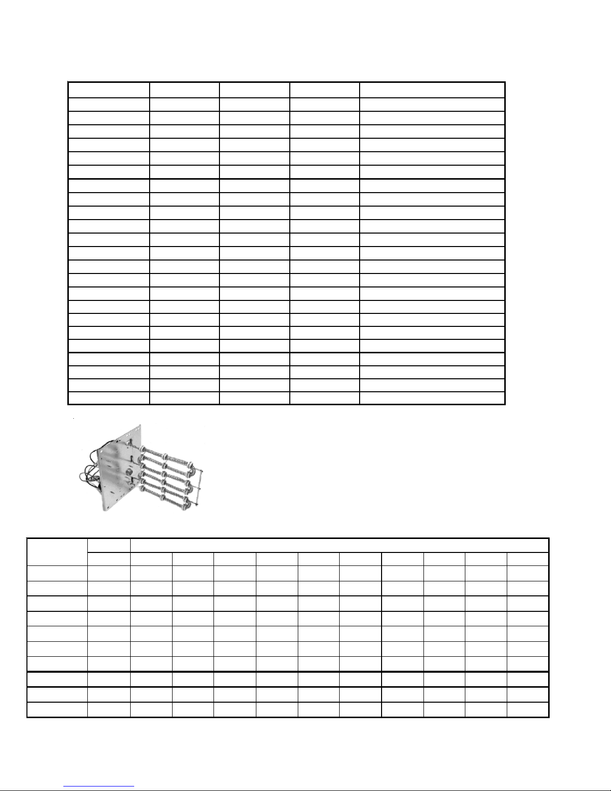
HKR SERIES ELECTRIC HEA T KITS
ELECTRIC HEAT KIT APPLICATIONS
MBR & MBE
BLOWER
MBR0800AA-1AA - X X X X X
MBR1200AA-1AA- XXXXXXXXXX
MBR1600AA-1AA- XXXXXXXXXX
MBR2000AA-1AA- XXXXXXXXXX
MBE1200AA-1AA - - - - X X X - - - MBE1600AA-1AA - - - - - X X - - - MBE2000AA-1AA - - - - - X X X - - MBE1200AA-1BA - X X X X X X - - - MBE1600AA-1BA - X X X X X X - - - MBE2000AA-1BA - X X X X X X X - - -
X = Allowable combinations ^ = Circuit 1: Single Phase for Air Handler Motor * = Revision level that my or may not be designated
- = Restricted combinations Circuit 2: 3-Phase for HKR3 Heater Kits C = Circuit Breaker option
NO HEAT HKR-03* HKR05-(C)' HKR-06* HKR-08(C)* HKR-10(C)* HKR-15(C)* HKR-20(C)* HKR-21(C)* ^HKR3-15* ^HKR3-20A
ELE CTRIC HEAT KIT
20
Page 23

PRODUCT DESIGN
This section gives a basic description of cooling unit operation, its various components and their basic operation.
Ensure your system is properly sized for heat gain and loss
according to methods of the Air Conditioning Contractors
Association (ACCA) or equivalent.
CONDENSING UNIT
These units are designed for free air discharge. Condensed
air is pulled through the condenser coil by a direct drive
propeller fan and then discharged from the cabinet top. The
unit requires no additional resistance (i.e. duct work) and
should not be added.
The GSH13, GSH14, ASH13 and VSH13 Heat Pump condensing units are designed for 208-230 dual voltage single
phase applications. The GSH13 3 ton model is available in
230V, 3 phase applications. The GSH13 4 and 5 ton models
are available for 230V, 3-phase and 460V, 3-phase applications.
The units range in size from 1.5 to 5-ton and have a rating of
13 and 14 SEER. SEER efficiency is dependent upon the unit
and its components. Refer to the "Technical Information"
manual of the unit you are servicing for further details.
The GSC13, GSC14 and ASC13 and VSC13 Condensing
Units are made in 1.5 through 5 ton sizes. They are designed
for 208-240 volt single phase applications. The GSC13 3 ton
model is available in 230V, 3 phase applications. The GSC13
4 and 5 ton models are available for 230V, 3-phase and 460V,
3-phase applications.
Suction and Liquid Line Connections
All units come equipped with suction and liquid valves
designed for connection to refrigerant-type copper. Front
seating valves are factory-installed to accept the field-run
copper. The total refrigerant charge needed for a normal
operation is also factory-installed. For additional refrigerant
line set information, refer to the "Technical Information"
manual of the unit you are servicing.
Compressors
GSC13, VSC13, GSH13 and VSH13 use a mix of reciprocating and scroll compressors, except for the VSC130181AA
which uses a rotary compressor. The ASC13 and ASH13 use
the Copeland Scroll® Compressor. There are a number of
design characteristics which differentiate the scroll compressor from the reciprocating compressor. One is the scroll. A
scroll is an involute spiral which, when matched with a mating
scroll form, generates a series of crescent-shaped gas
pockets between the members (see following illustration).
During compression, one scroll remains stationary while the
other form orbits. This motion causes the resulting gas
pocket to compress and push toward the center of the scrolls.
When the center is reached, the gas is discharged out a port
located at the compressor center.
GSC130361D* and GSC130481AG use Bristol® BENCHMARK™ compressors, the most advanced compressors in
the industry today. The BENCHMARK™ reciprocating compressor can be recognized by a “J” in the fourth character of
the compressor model number. Innovative mechanical design and gas management make the BENCHMARK™ compressor very efficient and remarkably quiet. The sound
content (frequency) delivers exceptional acoustical characteristics and the virtually round housing design is compact
and also helps to reduce the overall sound and vibration.
GSC130181BA use Panasonic® rotary compressors.
COILS AND BLOWER COILS
MBR/MBE blower cabinets are designed to be used as a twopiece blower and coil combination. MBR/MBE blower sections can be attached to cased evaporator coil. This twopiece arrangement allows for a variety of mix-matching
possibilities providing greater flexibility. The MBE blower
cabinet uses a variable speed motor that maintains a constant airflow with a higher duct static.
It is approved for applications with cooling coils of up to 0.8
inches W.C. external static pressure and includes a feature
that allows airflow to be changed by +15%. The MBR blower
cabinet uses a PSC motor. It is approved for applications with
cooling coils of up to 0.5 inches W.C. external static
pressure.
The MBR/MBE blower cabinets with proper coil matches can
be positioned for upflow, counterflow, horizontal right or
horizontal left operation. All units are constructed with R-4.2
insulation. In areas of extreme humidity (greater than 80%
consistently), insulate the exterior of the blower with insulation having a vapor barrier equivalent to ductwork insulation,
providing local codes permit.
The CAPX/CHPX coils are equipped with a thermostatic
expansion valve that has a built-in internal check valve for
refrigerant metering. The CACF/CAPF/CHPF coils are
equipped with a fixed restrictor orifice.
21
Page 24

PRODUCT DESIGN
The coils are designed for upflow, counterflow or horizontal
application, using two-speed direct drive motors on the
CACF/CAPF/CHPX models and BPM (Brushless Permanent
Magnet) or ECM motors on the MBE models.
The ARUF is a multi-position air handler (upflow/horizontal or
downflow) and is equipped with a flowrator for cooling and heat
pump applications. Because of its seamless copper tubing
and aluminum fins, there are fewer leaks. The steel cabinet
of the ARUF is fully insulated and rust resistant. Thermal
expansion kits for air conditioning and heat pump applications are available.
ARPF*B 2 to 5 ton air handlers are dedicated for downflow
operation and are approved for modular homes. Flowrater.
transformer and blower time delay are on all standard ARPF
units. Both the ARUF and ARPF have direct-drive multispeed motors.
AEPF is a multi-position, variable-speed air handler and can
be used with R-410A or R-22 (models ending in 1/16). The
unit's blower design includes a variable-speed DC motor and
is compatible with heat pumps and variable-capacity cooling
applications.
ASPF is a multi-position air handler that can be used with R410A or R-22 and it features a X-13 motor. This motor is a
constant torque motor with very low power consumption and
it is energized by a 24V signal. The X-13 features an
integrated control module and is compatible with heat pumps
and cooling applications.
22
Page 25

SYSTEM OPERA TION
COOLING
The refrigerant used in the system is R-22. It is a clear,
colorless, non-toxic, non-irritating, and non-explosive liquid.
The chemical formula is CHCLF
atmospheric pressure is -41.4°F.
A few of the important principles that make the refrigeration
cycle possible are: heat always flows from a warmer to a
cooler body, under lower pressure a refrigerant will absorb
heat and vaporize at a low temperature, the vapors may be
drawn off and condensed at a higher pressure and temperature to be used again.
The indoor evaporator coil functions to cool and dehumidify
the air conditioned spaces through the evaporative process
taking place within the coil tubes.
NOTE: The pressures and temperatures shown in the
refrigerant cycle illustrations on the following pages are for
demonstration purposes only. Actual temperatures and pressures are to be obtained from the "Expanded Performance
Chart."
Liquid refrigerant at condensing pressure and temperatures,
(270 psig and 122°F), leaves the outdoor condensing coil
through the drier and is metered into the indoor coil through
the metering device. As the cool, low pressure, saturated
refrigerant enters the tubes of the indoor coil, a portion of the
liquid immediately vaporizes. It continues to soak up heat and
vaporizes as it proceeds through the coil, cooling the indoor
coil down to about 48°F.
Heat is continually being transferred to the cool fins and tubes
of the indoor evaporator coil by the warm system air. This
warming process causes the refrigerant to boil. The heat
removed from the air is carried off by the vapor.
As the vapor passes through the last tubes of the coil, it
becomes superheated, that is, it absorbs more heat than is
necessary to vaporize it. This is assurance that only dry gas
will reach the compressor. Liquid reaching the compressor
can weaken or break compressor valves.
The compressor increases the pressure of the gas, thus
adding more heat, and discharges hot, high pressure superheated gas into the outdoor condenser coil.
In the condenser coil, the hot refrigerant gas, being warmer
than the outdoor air, first loses its superheat by heat transferred from the gas through the tubes and fins of the coil. The
refrigerant now becomes saturated, part liquid, part vapor and
then continues to give up heat until it condenses to a liquid
alone. Once the vapor is fully liquefied, it continues to give up
heat which subcools the liquid, and it is ready to repeat the
cycle.
. The boiling point, at
2
The check valve at the indoor coil will open by the flow of
refrigerant letting the now condensed liquid refrigerant bypass the indoor expansion device. The check valve at the
outdoor coil will be forced closed by the refrigerant flow,
thereby utilizing the outdoor expansion device.
The restrictor orifice used with the CA*F, CHPF coils and the
AR*F air handler will be forced onto a seat when running in
the cooling cycle, only allowing liquid refrigerant to pass
through the orifice opening. In the heating cycle it will be
forced off the seat allowing liquid to flow around the restrictor.
A check valve is not required in this circuit.
COOLING CYCLE
When the contacts of the room thermostat close making
terminals R to Y & G, the low voltage circuit of the transformer
is completed. Current now flows through the magnetic holding coils of the compressor contactor (CC) and fan relay
(RFC).
This draws in the normally open contact CC, starting the
compressor and condenser fan motors. At the same time
contacts RFC close starting the indoor fan motor.
When the thermostat is satisfied, it opens its contacts,
breaking the low voltage circuit, causing the compressor
contactor and indoor fan relay to open, shutting down the
system.
If the room thermostat fan selector switch should be set on
the "on" position, then the indoor blower would run continuous
rather than cycling with the compressor.
Heat pumps energize the reversing valve thorough the "O"
circuit in the room thermostat. Therefore the reversing valve
remains energized as long as the thermostat subbase is in
the cooling position. The only exception to this is during
defrost.
DEFROST CYCLE
The defrosting of the outdoor coil is jointly controlled by the
defrost timing board, defrost (30/60) control, and compressor
run time.
HEATING CYCLE
The reversing valve on the heat pump models is energized in
the cooling cycle through the "O" terminal on the room
thermostat.
These models have a 24 volt reversing valve coil. When the
thermostat selector switch is set in the cooling position, the
"O" terminal on the thermostat is energized all the time.
Care must be taken when selecting a room thermostat. Refer
to the installation instructions shipped with the product for
approved thermostats.
HEATING
The heating portion of the refrigeration cycle is similar to the
cooling cycle. By energizing the reversing valve solenoid coil,
the flow of the refrigerant is reversed. The indoor coil now
becomes the condenser coil, and the outdoor coil becomes
the evaporator coil.
23
Page 26
SYSTEM OPERA TION
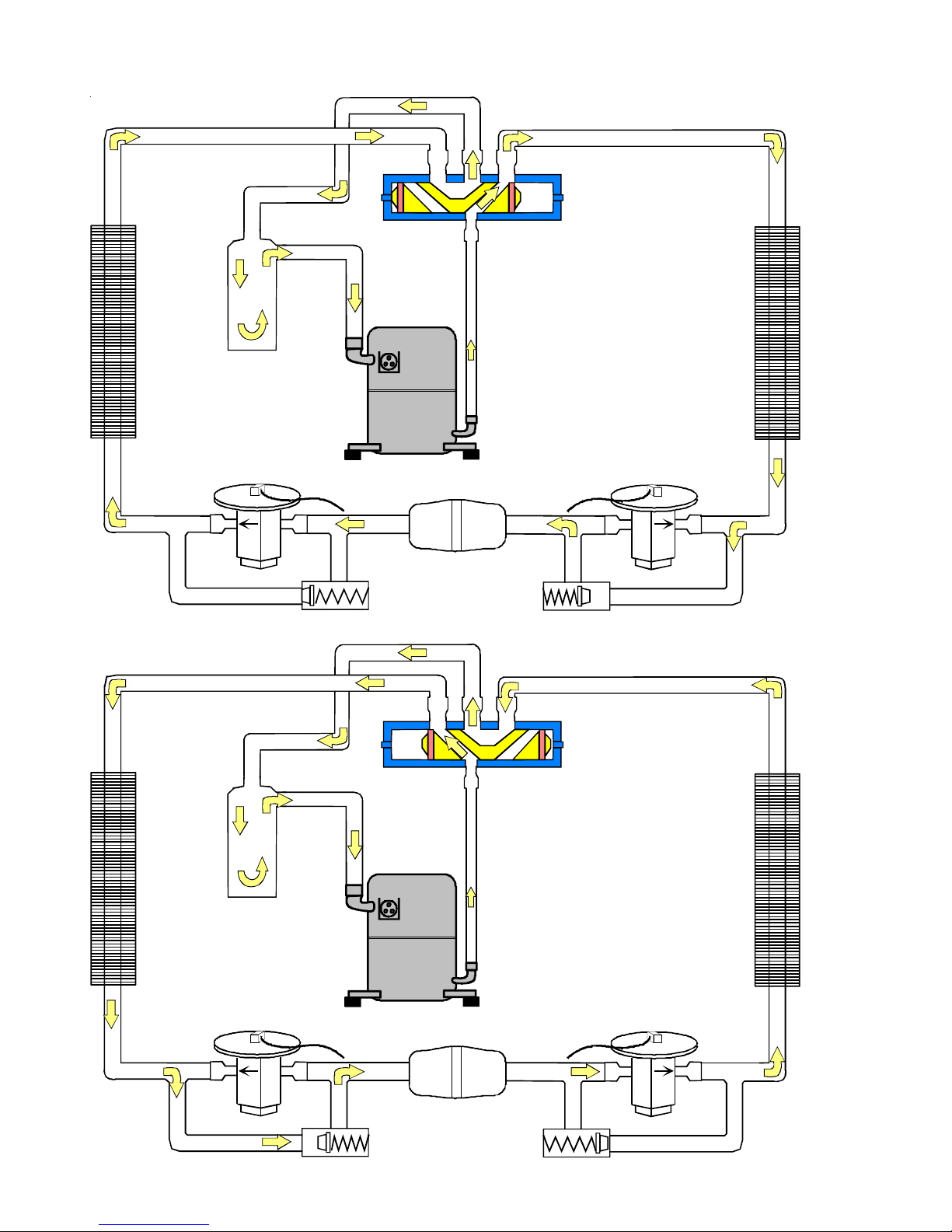
COOLING CYCLE
Reversing Valve
(Energized)
Indoor
Coil
HEATING CYCLE
Outdoor
Coil
Accumulator
Thermostatic
Expansion
Valve
Bi-Flow
Filter Dryer
Check Valve
Indoor
Coil
Accumulator
24
Reversing Valve
(De-Energized)
Outdoor
Coil
Thermostatic
Expansion
Valve
Bi-Flow
Filter Dryer
Check Valve
Page 27
SYSTEM OPERA TION
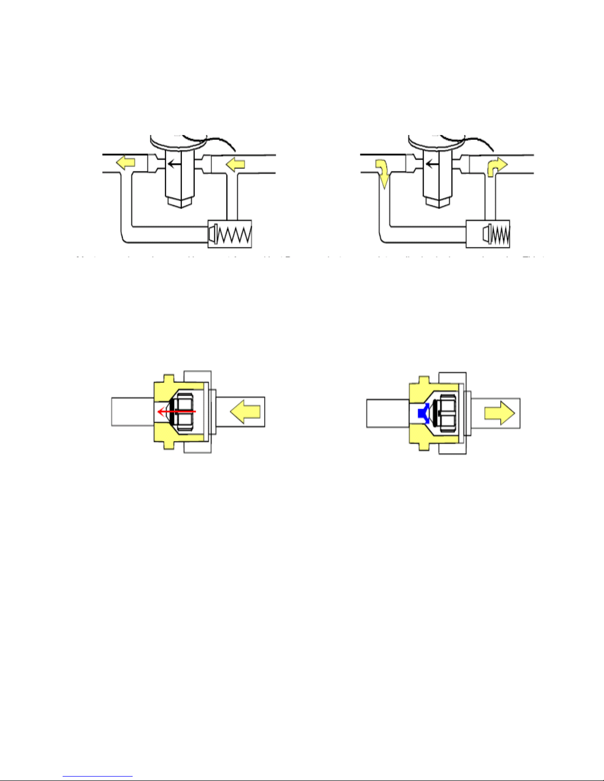
EXPANSION VALVE/CHECK VALVE ASSEMBLY
IN COOLING OPERATION
Most expansion valves used in current Amana
use an internally checked expansion valve.
This type of expansion valve does not require an external check valve as shown above.
However, the principle of operation is the same.
RESTRICTOR ORIFICE ASSEMBLY
IN COOLING OPERATION
EXPANSION VALVE/CHECK VALVE ASSEMBLY
IN HEATING OPERATION
®
Brand Heat Pump products
RESTRICTOR ORIFICE ASSEMBLY
IN HEATING OPERATION
In the cooling mode, the orifice is pushed into its
seat, forcing refrigerant to flow through the metered
hole in the center of the orifice.
In the heating mode, the orifice moves back off its
seat, allowing refrigerant to flow unmetered around
the outside of the orifice.
25
Page 28
SYSTEM OPERA TION
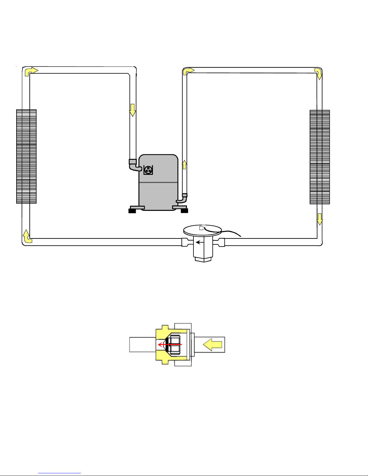
COOLING CYCLE - CONDENSING UNIT
Indoor
Coil
Outdoor
Coil
Thermostatic
Expansion
Valve
In the cooling mode, the orifice is pushed into its
seat, forcing refrigerant to flow through the metered
26
hole in the center of the orifice.
Page 29
SYSTEM OPERA TION
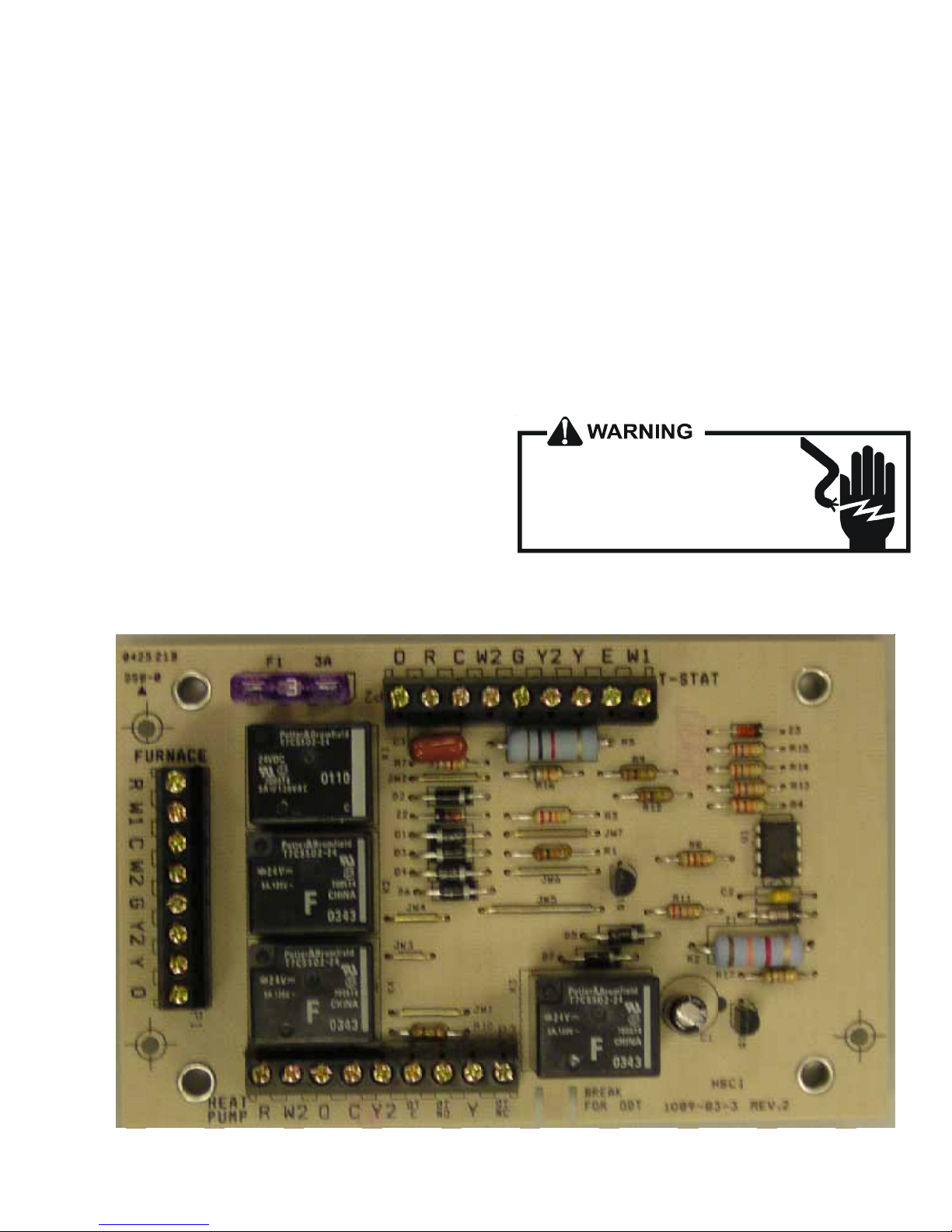
AFE18-60A CONTROL BOARD
DESCRIPTION
The AFE18 control is designed for use in heat pump applications where the indoor coil is located above/downstream of a
gas or fossil fuel furnace. It will operate with single and two
stage heat pumps and single and two stage furnaces. The
AFE18 control will turn the heat pump unit off when the
furnace is turned on. An anti-short cycle feature is also
incorporated which initiates a 3 minute timed off delay when
the compressor goes off. On initial power up or loss and
restoration of power, this 3 minute timed off delay will be
initiated. The compressor won’t be allowed to restart until the
3 minute off delay has expired. Also included is a 5 second
de-bounce feature on the “Y, E, W1 and O” thermostat inputs.
These thermostat inputs must be present for 5 seconds
before the AFE18 control will respond to it.
An optional outdoor thermostat, OT18-60A, can be used with
the AFE18 to switch from heat pump operation to furnace
operation below a specific ambient temperature setting, i.e.
break even temperature during heating. When used in this
manner, the “Y” heat demand is switched to the “W1” input
to the furnace by the outdoor thermostat and the furnace is
used to satisfy the first stage “Y” heat demand. On some
controls, if the outdoor thermostat fails closed in this position
during the heating season, it will turn on the furnace during
the cooling season on a “Y” cooling demand. In this
situation, the furnace produces heat and increases the
indoor temperature thereby never satisfying the cooling
demand. The furnace will continue to operate and can only
be stopped by switching the thermostat to the off position or
removing power to the unit and then replacing the outdoor
thermostat. When the AFE18 receives a “Y” and “O”
input from the indoor thermostat, it recognizes this as a
cooling demand in the cooling mode. If the outdoor thermostat is stuck in the closed position switching the “Y” demand
to the “W1” furnace input during the cooling mode as
described above, the AFE18 won’t allow the furnace to
operate. The outdoor thermostat will have to be replaced to
restore the unit to normal operation.
HIGH VOLTAGE!
Disconnect ALL power before servicing
or installing. Multiple power sources
may be present. Failure to do so may
cause property damage, personal injury
or death.
27
Page 30
TROUBLESHOOTING CHART
COOLING/HP ANALYSIS CHART
Complaint
POSSIBLE CAUSE
DOTS IN ANALYSIS
GUIDE INDICATE
"POSSIBLE CAUSE"
Power Failure
Blown Fuse
Unbalanced Power, 3PH
Loose Connection
Shorted or Broken Wires
Open Fan Overload
Faulty Thermostat
Faulty Transformer
Shorted or Open Capacitor
Internal Compressor Overload Open
Shorted or Grounded Compressor
Compressor Stuck
Faulty Compressor Contactor
Faulty Fan Relay
Open Control Circuit
Low Voltage
Faulty Evap. Fan Motor
Shorted or Grounded Fan Motor
Improper Cooling Anticipator
Shortage of Refrigerant
Restricted Liquid Line
Open Element or Limit on Elec. Heater
Dirty Air Filter
Dirty Indoor Coil
Not enough air across Indoor Coil
Too much air across Indoor Coil
Overcharge of Refrigerant
Dirty Outdoor Coil
Noncondensibles
Recirculation of Condensing Air
Infiltration of Outdoor Air
Improperly Located Thermostat
Air Flow Unbalanced
System Undersized
Broken Internal Parts
Broken Valves
Inefficient Compressor
Wrong Type Expansion Valve
Expansion Device Restricted
Oversized Expansion Valve
Undersized Expansion Valve
Expansion Valve Bulb Loose
Inoperative Expansion Valve
Loose Hold-down Bolts
Faulty Reversing Valve
Faulty Defrost Control
Faulty Defrost Thermostat
Flowrator Not Seating Properly
No Cooling Unsatisfactory Cooling/Heating
SYMPTOM
System will not start
Compressor will not start - fan runs
Comp. and Cond. Fan will not start
Evaporator fan will not start
Condenser fan will not start
Compressor runs - goes off on overload
Compressor cycles on overload
System runs continuously - little cooling/htg
Too cool and then too warm
Not cool enough on warm days
•
•••
•••
•••
••••••
••
••• •
••
• ••••
•
••
•••
•••
•
•
•••
••
••
••
••
•• •• •
♦♦
••• •
••• •
••• •
•• •
•• •
••
•• •
•••
••
••
••
•• ••
•
••• • ••
••• • •• •
••
••• • •
•• •
•
•
•
Cooling or Heating Cycle (Heat Pump) ♦
•••
System
Operating
Pressures
Certain areas too cool, others too warm
Compressor is noisy
System runs - blows cold air in heating
Unit will not terminate defrost
Unit will not defrost
Low suction pressure
Low head pressure
High suction pressure
High head pressure
Test Voltage S-1
Inspect Fuse Size & Type S-1
Test Voltage S-1
Inspect Connection - Tighten S-2, S-3
Test Circuits With Ohmmeter S-2, S-3
Test Continuity of Overload S-17A
Test Continuity of Thermostat & Wiring S-3
Check Control Circuit with Voltmeter S-4
Test Capacitor S-15
♦
♦
♦
♦
♦
♦
•
♦
••
♦
♦
••
••
•
♦♦♦ ♦♦♦
♦♦♦♦♦ ♦
♦♦♦♦♦♦♦
Heating Cycle Only (Heat Pump)
Test Continuity of Overload S-17A
Test Motor Windings S-17B
Use Test Cord S-17D
Test Continuity of Coil & Contacts S-7, S-8
Test Continuity of Coil And Contacts S-7
Test Control Circuit with Voltmeter S-4
Test Voltage S-1
Repair or Replace S-16
♦
Test Motor Windings S-16
Check Resistance of Anticipator S-3B
Test For Leaks, Add Refrigerant S-101,103
Remove Restriction, Replace Restricted Part S-112
Test Heater Element and Controls S-26,S-27
Inspect Filter-Clean or Replace
♦
Inspect Coil - Clean
♦
Check Blower Speed, Duct Static Press, Filter S-200
♦
Reduce Blower Speed S-200
•
Recover Part of Charge S-113
••
Inspect Coil - Clean
•
Recover Charge, Evacuate, Recharge S-114
•
Remove Obstruction to Air Flow
Check Windows, Doors, Vent Fans, Etc.
Relocate Thermostat
Readjust Air Volume Dampers
Refigure Cooling Load
Replace Compressor S-115
Test Compressor Efficiency S-104
Test Compressor Efficiency S-104
Replace Valve S-110
♦
Remove Restriction or Replace Expansion Device S-110
Replace Valve
Replace Valve
Tighten Bulb Bracket S-105
Check Valve Operation S-110
Tighten Bolts
Replace Valve or Solenoid S-21, 122
Test Control S-24
Test Defrost Thermostat S-25
Check Flowrator & Seat or Replace Flowrator S-111
Test Method
Remedy
See Service Procedure Ref.
28
Page 31

SERVICING
TABLE OF CONTENTS
S-1 Checking Voltage.......................................... 30
S-2 Checking Wiring............................................30
S-3 Checking Thermostat, Wiring & Anticipator .. 30
S-3A Thermostat & Wiring ..................................... 30
S-3B Cooling Anticipator ........................................ 31
S-3C Heating Anticipator........................................ 31
S-3D Checking Encoded Thermostats ................... 31
S-4 Checking Transformer & Control Circuit ....... 32
S-5 Checking Cycle Protector ............................. 32
S-6 Checking Time Delay Relay.......................... 32
S-7 Checking Contactor and/or Relays................ 33
S-8 Checking Contactor Contacts .......................33
S-9 Checking Fan Relay Contact ........................ 33
S-10 Copeland Comfort™ Alert Diagnostics .......... 3 4
S-11 Checking Loss of Charge Protector............... 36
S-15 Checking Capacitor....................................... 36
S-15A Resistance Check......................................... 37
S-15B Capacitance Check....................................... 3 7
S-16A Checking Fan & Blower Motor
Windings (PSC Motors) ............................... 37
S-16B Checking Fan & Blower Motor (ECM Motors) 3 8
S-16C Checking ECM Motor Windings .................... 41
S-16D ECM CFM Adjustments................................ 41
S-16E Checking GE X13™ Motors .......................... 42
S-17 Checking Compressor Windings ................... 43
S-17A Resistance Test............................................ 43
S-17B Ground Test .................................................. 43
S-17D Operation Test .............................................. 44
S-18 Testing Crankcase Heater (optional item) .....4 4
S-21 Checking Reversing Valve Solenoid .............. 44
S-24 Testing Defrost Control.................................. 44
S-25 Testing Defrost Thermostat ........................... 4 5
S-40 MBR & AR*F Electronic Blower Time Delay..45
S-41 MBE & AEPF with Single Speed
Air Conditioning............................................ 47
S-41A MBE & AEPF with Single Speed
Heat Pumps................................................. 47
S-60 Electric Heater (optional item)....................... 4 9
S-61A Checking Heater Limit Control(S).................. 50
S-61B Checking Heater Fuse Line........................... 50
S-62 Checking Heater Elements ........................... 5 0
S-100 Refrigeration Repair Practice......................... 50
S-101 Leak Testing .................................................5 1
S-102 Evacuation ....................................................51
S-103 Charging........................................................ 52
S-104 Checking Compressor Efficiency .................. 53
S-105A Piston Kit Chart ............................................ 53
S-105B Thermostatic Expansion Valve...................... 53
S-106 Overfeeding ...................................................54
S-107 Underfeeding ................................................. 54
S-108 Superheat ..................................................... 54
S-109 Checking Subcooling .................................... 55
S-110 Checking Expansion Valve Operation ........... 55
S-111 Fixed Orifice Restriction Devices .................. 56
S-112 Checking Restricted Liquid Line.................... 56
S-113 Refrigerant Overcharge .................................. 56
S-114 Non-condensables ........................................ 56
S-115 Compressor Burnout .....................................56
S-120 Refrigerant Piping.......................................... 57
S-122 Replacing Reversing Valve ............................ 59
S-202 Duct Static Pressure
& Static Pressure Drop Across Coils ............ 59
S-203 Air Handler External Static ........................... 5 9
S-204 Coil Static Pressure Drop ............................. 60
HIGH VOLTAGE!
DISCONNECT ALL POWER BEFORE SERVICING OR INSTALLING THIS
UNIT. MULTIPLE POWER SOURCES MAY BE PRESENT. F AILURE TO
DO SO MAY CAUSE PROPERTY DAMAGE, PERSONAL INJURY OR DEA T H.
29
Page 32

SERVICING
S-1 CHECKING VOLTAGE
1. Remove outer case, control panel cover, etc., from unit
being tested.
With power ON:
WARNING
Line Voltage now present.
S-2 CHECKING WIRING
2. Using a voltmeter, measure the voltage across terminals
L1 and L2 of the contactor for the condensing unit or at the
field connections for the air handler or heaters.
3. No reading - indicates open wiring, open fuse(s) no power
or etc., from unit to fused disconnect service. Repair as
needed.
4. With ample voltage at line voltage connectors, energize
the unit.
5. Measure the voltage with the unit starting and operating,
and determine the unit Locked Rotor Voltage. NOTE: If
checking heaters, be sure all heating elements are
energized.
Locked Rotor Voltage is the actual voltage available at
the compressor during starting, locked rotor, or a stalled
condition. Measured voltage should be above minimum
listed in chart below.
To measure Locked Rotor Voltage attach a voltmeter to
the run "R" and common "C" terminals of the compressor,
or to the T1 and T2 terminals of the contactor. Start the unit
and allow the compressor to run for several seconds, then
shut down the unit. Immediately attempt to restart the
unit while measuring the Locked Rotor Voltage.
6. Lock rotor voltage should read within the voltage tabulation as shown. If the voltage falls below the minimum
voltage, check the line wire size. Long runs of undersized
wire can cause low voltage. If wire size is adequate, notify
the local power company in regard to either low or high
voltage.
REMOTE CONDENSING UNITS
BLOWER COILS
VOLTAGE MIN. MAX.
208/230 198 253
115 104 127
1. Check wiring visually for signs of overheating, damaged
insulation and loose connections.
2. Use an ohmmeter to check continuity of any suspected
open wires.
3. If any wires must be replaced, replace with comparable
gauge and insulation thickness.
S-3 CHECKING THERMOSTAT, WIRING, AND
ANTICIPATOR
THERMO ST AT WIRE SIZ ING CHA RT
LENGTH OF RUN
25 fe et 18
50 fe et 16
75 fe et 14
100 fe et 14
125 fe et 12
150 fe et 12
M IN. COPPER WI RE
GAUGE (AWG)
S-3A THERMOSTAT AND WIRING
WARNING
Line Voltage now present.
With power ON, thermostat calling for cooling
1. Use a voltmeter to check for 24 volts at thermostat wires
C and Y in the condensing unit control panel.
2. No voltage indicates trouble in the thermostat, wiring or
external transformer source.
3. Check the continuity of the thermostat and wiring. Repair
or replace as necessary.
Indoor Blower Motor
With power ON:
NOTE: When operating electric heaters on voltages other
than 240 volts, refer to the System Operation section on
electric heaters to calculate temperature rise and air flow.
Low voltage may cause insufficient heating.
30
WARNING
Line Voltage now present.
1. Set fan selector switch at thermostat to "ON" position.
2. With voltmeter, check for 24 volts at wires C and G.
3. No voltage indicates the trouble is in the thermostat or
wiring.
Page 33

SERVICING
4. Check the continuity of the thermostat and wiring. Repair
or replace as necessary.
Resistance Heaters
1. Set room thermostat to a higher setting than room
temperature so both stages call for heat.
2. With voltmeter, check for 24 volts at each heater relay.
Note: BBA/BBC heater relays are DC voltage.
3. No voltage indicates the trouble is in the thermostat or
wiring.
4. Check the continuity of the thermostat and wiring. Repair
or replace as necessary.
NOTE: Consideration must be given to how the heaters are
wired (O.D.T. and etc.). Also safety devices must be checked
for continuity.
S-3B COOLING ANTICIPATOR
The cooling anticipator is a small heater (resistor) in the
thermostat. During the "off" cycle, it heats the bimetal
S-3D TROUBLESHOOTING ENCODED TWO STAGE COOLING THERMOSTATS OPTIONS
element helping the thermostat call for the next cooling cycle.
This prevents the room temperature from rising too high
before the system is restarted. A properly sized anticipator
should maintain room temperature within 1 1/2 to 2 degree
range.
The anticipator is supplied in the thermostat and is not to be
replaced. If the anticipator should fail for any reason, the
thermostat must be changed.
S-3C HEATING ANTICIPATOR
The heating anticipator is a wire wound adjustable heater
which is energized during the "ON" cycle to help prevent
overheating of the conditioned space.
The anticipator is a part of the thermostat and if it should fail
for any reason, the thermostat must be replaced. See the
following tables for recommended heater anticipator setting
in accordance to the number of electric heaters installed.
Troubleshooting Encoded Two Stage Cooling Thermostats Options
T
E
S
T
TEST FUNCTION SIGNAL OUT SIGNAL FAN
INDICATION
INPUT
FROM
THERMOSTAT
POWER
TO
THERMOSTAT
S1 +
* S1 - *
S1 + -
S2 +
S2 -
S2 + -
S3 +
* S3 - *
* S3 + - *
R + -
COM
NOTES:
1.) THE TEST SPADE CAN BE CONNECTED TO ANY OTHER TEST SPADE ON EITHER BOARD.
2.) THE + LED WILL BE RED AND WILL LIGHT TO INDICATE + HALF CYCLES.
THE - LED WILL BE GREEN AND WILL LIGHT TO INDICATE - HALF CYCLES.
BOTH RED AND GREEN ILLUMINATED WILL INDICATE FULL CYCLES DENOTED BY + - .
3.) SIGNAL OUT CONDITION FOR W1 , W2 HEATER WILL BE AFFECTED BY OT1 PJ4 AND OT2 PJ2
JUMPERS AND OUTDOOR THERMOSTATS ATTACHED. THE TABLE ABOVE ASSUMES OT1 PJ4 IS
REMOVED AND OT2 PJ2 IS MADE WITH NO OUTDOOR THERMOSTATS ATTACHED.
LOW SPEED COOL
* LO SPEED COOL *
HI SPEED COOL
LO SPEED HEAT
O
LO SPEED HEAT
HI SPEED HEAT
G
N/A
N/A
24 VAC
GND
YCON +
* YCON - *
YCON + -
W1 HEATER
ED -
( FUTURE USE )
W1 HEATER
W2 HEATER
NONE
N/A
N/A
R TO T'STAT
COM TO T'STAT
Y1
* Y / Y2 HI *
Y / Y2
W / W1
O
W / W1
EM / W2
G
N/A
N/A
R
C1 , C2
* ERROR CONDITION ( DIODE ON THERMOSTAT BA CKWARDS )
SEE NOTE 3
SEE NOTE 3
* ERROR CONDITION ( S3 CAN ONLY READ + )
* ERROR CONDITION ( S3 CAN ONLY READ + )
The chart above provides troubleshooting for either version of the encoded thermostat option. This provides diagnostic
information for the GMC CHET18-60 or a conventional two cool / two stage heat thermostat with IN4005 diodes added as called
out in the above section.
A test lead or jumper wire can be added from the test terminal to any terminal on the B13682-74 or B13682-71 variable speed
terminal board and provide information through the use of the LED lights on the B13682-71 VSTB control. Using this chart,
a technician can determine if the proper input signal is being received by the encoded VSTB control and diagnose any
problems that may be relayed to the output response of the B13682-74 VSTM control.
31
Page 34

SERVICING
S-4 CHECKING TRANSFORMER
AND CONTROL CIRCUIT
A step-down transformer (208/240 volt primary to 24 volt secondary) is provided with each indoor unit. This allows ample
capacity for use with resistance heaters. The outdoor sections do not contain a transformer.
With power ON:
WARNING
Line Voltage now present.
1. Apply 24 VAC to terminals R1 and R2.
2. Should read 24 VAC at terminals Y1 and Y2.
3. Remove 24 VAC at terminals R1 and R2.
4. Should read 0 VAC at Y1 and Y2.
5. Reapply 24 VAC to R1 and R2 - within approximately
three (3) to four (4) minutes should read 24 VAC at Y1 and
Y2.
If not as above - replace relay.
WARNING
Disconnect ALL power before servicing.
1. Remove control panel cover, or etc., to gain access to
transformer.
With power ON:
WARNING
Line Voltage now present.
2. Using a voltmeter, check voltage across secondary voltage side of transformer (R to C).
3. No voltage indicates faulty transformer, bad wiring, or bad
splices.
4. Check transformer primary voltage at incoming line voltage connections and/or splices.
5 If line voltage available at primary voltage side of trans-
former and wiring and splices good, transformer is inoperative. Replace.
S-5 CHECKING CYCLE PROTECTOR
Some models feature a solid state, delay-on make after break
time delay relay installed in the low voltage circuit. This
control is used to prevent short cycling of the compressor
under certain operating conditions.
The component is normally closed (R1 to Y1). A power
interruption will break circuit (R1 to Y1) for approximately three
minutes before resetting.
S-6 CHECKING TIME DELAY RELAY
Time delay relays are used in some of the blower cabinets to
improve efficiency by delaying the blower off time. Time
delays are also used in electric heaters to sequence in
multiple electric heaters.
WARNING
Disconnect ALL power before servicing.
1. Tag and disconnect all wires from male spade connections of relay.
2. Using an ohmmeter, measure the resistance across
terminals H1 and H2. Should read approximately 150
ohms.
3. Using an ohmmeter, check for continuity across terminals 3 and 1, and 4 and 5.
4. Apply 24 volts to terminals H1 and H2. Check for
continuity across other terminals - should test continuous. If not as above - replace.
NOTE: The time delay for the contacts to make will be
approximately 20 to 50 seconds and to open after the coil is
de-energized is approximately 40 to 90 seconds.
OHMMETER
1. Remove wire from Y1 terminal.
2. Wait for approximately four (4) minutes if machine was
running.
32
TESTING COIL CIRCUIT
Page 35

SERVICING
S-7 CHECKING CONTACTOR AND/OR RELAYS
WARNING
HIGH VOLTAGE!
Disconnect ALL power before servicing or installing.
Multiple power sources may be present. Failure to do
so may cause property dama ge, p ersonal injur y
or death.
The compressor contactor and other relay holding coils are
wired into the low or line voltage circuits. When the control
circuit is energized, the coil pulls in the normally open
contacts or opens the normally closed contacts. When the
coil is de-energized, springs return the contacts to their
normal position.
NOTE: Most single phase contactors break only one side of
the line (L1), leaving 115 volts to ground present at most
internal components.
1. Remove the leads from the holding coil.
2. Using an ohmmeter, test across the coil terminals.
If the coil does not test continuous, replace the relay or
contactor.
S-8 CHECKING CONTACTOR CONTACTS
T2
CC
VOLT/OHM
METER
Ohmmeter for testing holding coil
Voltmete r f o r te st in g con ta cts
TESTING COMPRESSOR CONTACTOR
S-9 CHECKING FAN RELAY CONTACTS
T1
L1L2
WARNING
DISCONNECT ELECTRICAL POWER SUPPLY.
Disconnect Electrical Power Supply:
1. Disconnect the wire leads from the terminal (T) side of the
contactor.
2. With power ON, energize the contactor.
WARNING
Line Voltage now present.
3. Using a voltmeter, test across terminals.
A. L2 - T1 - No voltage indicates CC1 contacts open.
If a no voltage reading is obtained - replace the contactor.
1. Disconnect wires leads from terminals 2 and 4 of Fan
Relay Cooling and 2 and 4, 5 and 6 of Fan Relay Heating.
2. Using an ohmmeter, test between 2 and 4 - should read
open. Test between 5 and 6 - should read continuous.
3. With power ON, energize the relays.
WARNING
Line Voltage now present.
4
OHMMETER
TESTING FAN RELAY
4. Using an ohmmeter, test between 2 and 4 - should read
continuous . Test between 5 and 6 - should read open.
5. If not as above, replace the relay.
2
5
3
1
33
Page 36

SERVICING
S-10 COPELAND COMFORT ALERT™
DIAGNOSTICS
Applies to ASC13 & ASH13
Comfort Alert™ is self-contained with no required external
sensors and is designed to install directly into the electrical
box of any residential condensing unit that has a Copeland
Scroll™ compressor inside.
Once attached, Comfort Alert™ provides around-the-clock
monitoring for common electrical problems, compressor
defects and broad system faults. If a glitch is detected, an
LED indicator flashes the proper alert codes to help you
quickly pinpoint the problem. See Diagnostic Table on
following page.)
34
Page 37

SERVICING
DIAGNOSTICS TABLE
Status LED Status LED Description Status LED Troubleshooting Information
Green “POWER” M odule has power
Red “TRIP”
Yellow “ALERT” Long Run Time
Flash Code 1
Yellow “ALERT” System Pressure Trip
Flash Code 2
Yellow “ALERT” Short Cycling
Flash Code 3
Yellow “ALERT” Locked Rotor
Flash Code 4
Yellow “ALERT” Open Circuit
Flash Code 5
Yellow “ALERT” Open Start Circuit
Flash Code 6
Yellow “ALERT” Open Run Circuit
Flash Code 7
Yellow “ALERT” Welded Contactor
Flash Code 8
Yellow “ALERT” Low Voltage
Flash Code 9
• Flash Code number corresponds to a number of LED flashes, followed by a pause and then repeated
• TRIP and ALERT LEDs flashing at same time means control circuit voltage is too low for operation.
• Reset ALERT Flash code by removing 24VAC power from module
• Last ALERT Flash code is displayed for 1 minute after module is powered on.
Thermostat demand signal 1. Compressor protector is open
Y1 is present, but the 2. Outdoor unit power disconn ect is open
compressor is not 3. Compressor circuit breaker or fuse(s) is open
running 4. Broken wire or connector is not making contact
Compressor is 2. Evaporator blower is not running
running ext remely 3. Evaporator coil is frozen
long run cycles 4. Faulty metering device
Discharge or suction 2. Condenser co il poor air circulation (dirty, blocked, damaged)
pressure out of limits or 3. Co ndenser fan is not running
compressor overloaded 4. Return air duct has substantial leakage
Compressor is running 2. Time delay relay or control board defective
only briefly 3. If high pressure switch present go to Flash Code 2 information
Current only in run circuit 2. Open circuit in compressor start wiring or connections
Current only in start circuit 2. Compressor run winding is damaged
Compressor always runs 2. Thermostat demand signal not connected to module
Control circuit < 17VAC 2. Low line voltage (contact utility if voltage at disconnect is low)
Supply voltage is present at module terminals
5. Low pressure switch open if present in system
6. Compressor contactor has failed open
1. Low refrigerant charge
5. Condenser coil is dirty
6. Liquid line restriction (filter drier blocked if present in sy stem)
7. Thermostat is malfunc tioning
1. High head pressure
5. If low pressure switch present in system,
check Flash Code 1 information
1. Thermostat demand sign al is intermittent
4. If low pressure switch present go to Flash Code 1 information
1. Run capaci tor has failed
2. Low line voltage ( c ontact utility if voltage at disc onnect is low)
3. Excessive liquid refrigerant in compressor
4. Compre ssor bearings are seized
1. Outdoor unit power disconnect is open
2. Compre ssor circuit breaker or fuse(s) is open
3. Compressor contactor has failed open
4. High press ure switch is open and requires manual reset
5. Open circ uit in compressor supply wiring or connections
6. Unusually long compressor protector reset time
due to extreme ambient temperature
7. Compressor windings are damaged
1. Run capaci tor has failed
3. Compressor start win ding is damaged
1. Open circuit in compressor run wiring or connections
1. Compressor contactor has failed closed
1. Control circuit transformer is overloaded
35
Page 38

SERVICING
S-11 CHECKING LOSS OF CHARGE PROTECTOR
(Heat Pump Models)
The loss of charge protector senses the pressure in the liquid
line and will open its contacts on a drop in pressure. The low
pressure control will automatically reset itself with a rise in
pressure.
The low pressure control is designed to cut-out (open) at
approximately 7 PSIG. It will automatically cut-in (close) at
approximately 25 PSIG.
Test for continuity using a VOM and if not as above, replace
the control.
S-15 CHECKING CAPACITOR
CAPACITOR, RUN
A run capacitor is wired across the auxiliary and main
windings of a single phase permanent split capacitor motor.
The capacitors primary function is to reduce the line current
while greatly improving the torque characteristics of a motor.
This is accomplished by using the 90° phase relationship
between the capacitor current and voltage in conjunction with
the motor windings, so that the motor will give two phase
operation when connected to a single phase circuit. The
capacitor also reduces the line current to the motor by
improving the power factor.
The line side of this capacitor is marked with "COM" and is
wired to the line side of the circuit.
CAPACITOR, START
SCROLL COMPRESSOR MODELS
In most cases hard start components are not required on
Scroll compressor equipped units due to a non-replaceable
check valve located in the discharge line of the compressor.
However, in installations that encounter low lock rotor voltage, a hard start kit can improve starting characteristics and
reduce light dimming within the home. Only hard start kits
approved by Amana
"Kick Start" and/or "Super Boost" kits are not approved start
assist devices.
The discharge check valve closes off high side pressure to the
compressor after shut down allowing equalization through the
scroll flanks. Equalization requires only about ½ second.
To prevent the compressor from short cycling, a Time Delay
Relay (Cycle Protector) has been added to the low voltage
circuit.
RELAY, START
A potential or voltage type relay is used to take the start
capacitor out of the circuit once the motor comes up to speed.
This type of relay is position sensitive. The normally closed
contacts are wired in series with the start capacitor and the
relay holding coil is wired parallel with the start winding. As
the motor starts and comes up to speed, the increase in
voltage across the start winding will energize the start relay
holding coil and open the contacts to the start capacitor.
Two quick ways to test a capacitor are a resistance and a
capacitance check.
36
®
brand or Copeland should be used.
START
CAPACITO R
VIOLET 20
YELLOW 12
M
M
N
R
A
O
E
F
C
H
RUN
CAPACITOR
RED 10
START
RELAY
ORANGE 5
T2 T1
L1L2
CONTACTOR
HARD START KIT WIRING
S-15A RESISTANCE CHECK
1. Discharge capacitor and remove wire leads.
WARNING
Discharge capacitor through a 20 to 30 OHM
resistor before handling.
OHMMETER
CAPACITOR
TESTING CAPACITOR RESISTANCE
2. Set an ohmmeter on its highest ohm scale and connect
the leads to the capacitor -
A. Good Condition - indicator swings to zero and slowly
returns to infinity. (Start capacitor with bleed resistor will
not return to infinity. It will still read the resistance of the
resistor).
Page 39

SERVICING
B. Shorted - indicator swings to zero and stops there replace.
C. Open - no reading - replace. (Start capacitor would
read resistor resistance.)
S-15B CAPACITANCE CHECK
Using a hookup as shown below, take the amperage and
voltage readings and use them in the formula:
VOLTMETER
15 AMP
FUSE
AMMETER
1. Remove the motor leads from its respective connection
points and capacitor (if applicable).
2. Check the continuity between each of the motor leads.
3. Touch one probe of the ohmmeter to the motor frame
(ground) and the other probe in turn to each lead.
If the windings do not test continuous or a reading is obtained
from lead to ground, replace the motor.
S-16B CHECKING FAN AND BLOWER MOTOR
(ECM MOTORS)
An ECM is an Electronically Commutated Motor which offers
many significant advantages over PSC motors. The ECM
has near zero rotor loss, synchronous machine operation,
variable speed, low noise, and programmable air flow. Because of the sophisticated electronics within the ECM
motor, some technicians are intimated by the ECM motor;
however, these fears are unfounded. GE offers two ECM
motor testers, and with a VOM meter, one can easily perform
basic troubleshooting on ECM motors. An ECM motor
requires power (line voltage) and a signal (24 volts) to
operate. The ECM motor stator contains permanent magnet.
As a result, the shaft feels "rough" when turned by hand. This
is a characteristic of the motor, not an indication of defective
bearings.
CAPACITOR
TESTING CAPACITANCE
WARNING
Discharge capacitor through a 20 to 30 OHM
resistor before handling.
Capacitance (MFD) = 2650 X Amperage
Voltage
S-16A CHECKING FAN AND BLOWER MOTOR
WINDINGS (PSC MOTORS)
The auto reset fan motor overload is designed to protect the
motor against high temperature and high amperage conditions by breaking the common circuit within the motor, similar
to the compressor internal overload. However, heat generated within the motor is faster to dissipate than the compressor, allow at least 45 minutes for the overload to reset, then
retest.
WARNING
Line Voltage now present.
1. Disconnect the 5-pin connector from the motor.
2. Using a volt meter, check for line voltage at terminals #4
& #5 at the power connector. If no voltage is present:
3. Check the unit for incoming power See section S-1.
4. Check the control board, See section S-40.
5. If line voltage is present, reinsert the 5-pin connector and
remove the 16-pin connector.
6. Check for signal (24 volts) at the transformer.
7. Check for signal (24 volts) from the thermostat to the "G"
terminal at the 16-pin connector.
8. Using an ohmmeter, check for continuity from the #1 &
#3 (common pins) to the transformer neutral or "C"
thermostat terminal. If you do not have continuity, the
motor may function erratically. Trace the common circuits, locate and repair the open neutral.
9. Set the thermostat to "Fan-On". Using a voltmeter,
check for 24 volts between pin # 15 (G) and common.
10.Disconnect power to compressor. Set thermostat to call
for cooling. Using a voltmeter, check for 24 volts at pin #
6 and/or #14.
11.Set the thermostat to a call for heating. Using a voltmeter, check for 24 volts at pin #2 and/or #11.
37
Page 40

SERVICING
A
1
2
3
4
Lines 1 and 2 will be connected
for 12OVAC Power Connector
}
applications only
Gnd
AC Line Connection
4. Using an ohmmeter, check the motor windings for
continuity to ground (pins to motor shell). If the ohmmeter indicates continuity to ground, the motor is defective
and must be replaced.
5. Using an ohmmeter, check the windings for continuity
(pin to pin). If no continuity is indicated, the thermal limit
(over load) device may be open. Allow motor to cool and
retest.
5
OUT - OUT +
DJUST +/-
Y1 Y/Y2
COOL
DELAY
COMMON2
W/W1
COMMON1 O (REV VALVE)
AC Line Connection
816
7
15
G (FAN)
6
14
5
13
EM Ht/W2
4
12
24 Vac (R)
3
11
HEAT
2
10
BK/PWM (SPEED)
19
16-PIN ECM HARNESS CONNECTOR
If you do not read voltage and continuity as described, the
problem is in the control or interface board, but not the motor.
If you register voltage as described , the ECM power head is
defective and must be replaced.
S-16C CHECKING ECM MOTOR WINDINGS
1. Disconnect the 5-pin and the 16-pin connectors from the
ECM power head.
2. Remove the 2 screws securing the ECM power head and
separate it from the motor.
3. Disconnect the 3-pin motor connector from the power
head and lay it aside.
3-pin m otor
connector
16-pin
connector
5-pin
connector
S-16D ECM CFM ADJUSTMENTS
MBE MOTOR
This section references the operation characteristics of the
MBE model motor only. The ECM control board is factory
set with the dipswitch #4 in the “ON” position and all other
dipswitches are factory set in the “OFF” position. When
MBE is used with 2-stage cooling units, dipswitch #4
should be in the "OFF" position.
For most applications, the settings are to be changed
according to the electric heat size and the outdoor unit
selection.
The MBE product uses a General Electric ECMTM motor.
This motor provides many features not available on the
traditional PSC motor. These features include:
• Improved Efficiency
• Constant CFM
• Soft Start and Stop
• Improved Humidity Control
MOTOR SPEED ADJUSTMENT
Each ECM™ blower motor has been preprogrammed for
operation at 4 distinct airflow levels when operating in
Cooling/Heat Pump mode or Electric Heat mode. These 4
distinct levels may also be adjusted slightly lower or higher
if desired. The adjustment between levels and the trim
adjustments are made by changing the dipswitch(s) either
to an "OFF" or "ON" position.
38
Page 41

SERVICING
(
y
)
g
I
d
t
d
i
l
gg
d?
Ch
k
f
l
i
fl
(t
h
l
t
t
ity)
Check
for
undercharged
condition
Check
and
plug
leaks
in
return
ducts
cabinet
I
t
t
N
t
U
i
g
th
g
t
/
t
l
d
l
id
ll
d
t
ti
d
y
d
t
d
lt
y
y
g
g
g
y
y
y
different
- Turn power OFF prior to repa ir .
Wait 5 minutes after
disconnecting power before
opening motor.
- Handle electronic motor/control with care.
- Check 230 Vac power at motor.
- Check low voltage (24 Vac R to C) at motor.
- Check low voltage co nnections
(G, Y, W, R, C) at motor.
- Check for unseated pins in connectors
on motor harness .
- Test with a temporary jumper between R - G.
-
---- ---- ----
- Manual disconnect switch off or
door switch open.
- Blown fuse or ci rcuit breaker.
- 24 Vac wires miswired.
- Unseated pins in wiring
harness connectors.
- Bad motor/control module.
- Moisture present in motor or control module.
Troubleshooting Chart for ECM Variable Speed Air Circulator Blower Motors
- This is normal start-up for
variable speed mo tor.
Symptom Fault Description(s) Possible Causes Corrective Action Cautions and No tes
- Motor rocks
slightly
when starting.
- No movement.
- Motor won't
start.
have completel
- Turn power OFF prior to repa ir .
Wait 5 minutes after
disconnecting power before
opening motor.
- Handle electronic motor/control with care.
- Check for loos e motor mount.
- Make sure blower wheel is tight on shaft.
- Perform mot or/control replacement chec k,
ECM motors only.
- Turn power OFF prior to repa ir .
- Check line voltage for variation or "sag".
- Check low voltage co nnections
(G, Y, W, R, C) at
motor, unseated pins in motor
harness connect ors.
- Check-out system controls - Thermostat.
- Perform Moisture Check.*
- Turn power OFF prior to repa ir .
- Does removing panel or filter
reduce "puffing"?
- Check/replace filter.
- Check/correct duct restrictions.
- Adjust to correct blower speed setting.
.
.
capac
look alike, different modules ma
,
en
a
h the
oo muc
ow
r
modes. Even thou
ow a
or
e harnesses with "dr i p loop" under motor.
ec
-
s.
resu
e
uce unexpec
rammed for specific operatin
pro
pro
ma
.- Arran
---- ---- ----
es an
are factor
warran
CHART CONTINUED ON NEXT PAGE
uc
pro
s a
- Incorrect or dirty filter(s).
- Incorrect s upply or return ductwork.
- Variation in 230 Vac to motor.
- Unseated pins in wiring harness
connectors.
- Erratic CFM command from
"BK" terminal.
- Improper thermostat connection or set ting.
- Loose motor mount.
- Blower wheel not tight on motor shaft.
- Bad motor/control module.
- Moisture present in motor/control module.
- Incorrect blower speed setting.
equipment manufacturer
e vo
u
mo
ro
con
or
. -
or as recommended b
e
- "Hunts" or "puf fs" at
- It is normal for motor to
oscillate with
- Motor rocks,
but won't start.
no load on shaft.
- Varies up and down
or intermittent.
high CFM (speed).
u
n p
ra
e
ensa
s con
-
*Moisture Check
- Motor
oscillates up &
down while
being tested
off of blower.
- Motor starts,
but runs
erratically.
- Connectors a re oriented "down"
mo
e wron
n
s
e:
o
an
You must use the correct replacement control/motor module since the
mpor
functionality. The ECM variable speed motors are c
-
Note:
39
Page 42

SERVICING
(
y
)
g
I
d
t
d
i
l
gg
d?
Ch
k
f
l
i
fl
(t
h
l
t
t
ity)
Check
for
undercharged
condition
Check
and
plug
leaks
in
return
ducts
cabinet
I
t
t
N
t
U
i
g
th
g
t
/
t
l
d
l
id
ll
d
t
ti
d
y
d
t
d
lt
y
y
g
g
g
y
y
y
different
- Turn power OFF prior to repair.
Wait 5 minutes after
disconnecting power bef ore
opening motor.
- Handle electronic motor/control
with care.
- Turn power OFF prior to repair.
Wait 5 minutes after
disconnecting power bef ore
opening motor.
- Handle electronic motor/control
- Check low voltage (Thermostat)
wires and connections .
- Verify fan is not in delay mode -
wait until delay com plete.
- Perform mot or /control replacement
check, ECM motors only.
- Is fan in delay m ode? - wait until delay time complete.
- Perform mot or /control replacement check , ECM
motors only.
CHART CONTINUED FROM PREVIOUS PAGE
- 24 Vac wires mis wir ed or loose.
- "R" missing/not connected at motor.
- Fan in delay mode.
- "R" missing/not connected at motor.
- Fan in delay mode.
Troubleshooting Chart for ECM Variable Speed Air Circulator Blower Motors
40
Symptom Fault Description(s) Possible Causes Corrective Action Cautions and Notes
- Stays at low CFM despit e
system call for cool
or heat CFM.
- Stays at high CF M.
- Motor starts,
but runs
erratically.
have completel
with care.
- Turn power OFF prior to repair.
- Check for Triac switched t'stat
or solid state rel ay .
- Turn power OFF prior to repair.
- Check/replace filter.
- Check/correct duct restrictions.
- Adjust to corr ec t blower speed setting.
- Check for loose b lower ho us ing,
- Turn power OFF prior to repair.
panels, etc.
- Check for air whist ling thru seams in
ducts, cabi nets or panels.
- Check for cabine t/duct deformation.
- Turn power OFF prior to repair.
- Does removing panel or filter
reduce "puffing"?
- Check/replace filter.
- Turn power OFF prior to repair.
Wait 5 minutes after
disconnecting power bef ore
opening motor.
- Handle electronic motor/control
with care.
.
.
capac
look alike, different modules ma
,
en
a
h the
oo muc
ow
r
modes. Even thou
ow a
or
e harnesses with "drip loop" under motor.
ec
-
- Check/correct duct restrictions.
- Adjust to corr ec t blower speed setting.
- Replace motor and per form
Moisture Check.*
s.
resu
e
uce unexpec
rammed for specific operatin
pro
pro
ma
.- Arran
es an
are factor
warran
uc
pro
s a
- Current leakage from controls
into G, Y, or W.
- High static creating high blower speed.
- Incorrect s upply or return ductwork.
- Incorrect or dirty filter(s).
- Incorrect blower speed setting.
- Loose blower housing, panels, etc.
- High static c reating high blower
speed.
- Air leaks in ductwork, cabinets,
or panels.
- High static creating high blower speed.
- Incorrect or dirty filter(s).
- Incorrect s upply or return ductwork.
- Incorrect blower speed setting.
- Moisture in mo tor/control module.
equipment manufacturer
e vo
u
mo
ro
con
or
. -
or as recommended b
e
- Blower won't shut off.
- Air noise.
- Noisy blower or cabinet.
- "Hunts" or "puffs" at
high CFM (speed).
- Motor failure or
malfunction has
occurred and moisture
is present.
u
n p
ra
e
ensa
s con
*Moisture Check
-
- Evidence of
- Excessive
noise.
Moisture.
- Connectors are oriented "down"
mo
e wron
n
s
e:
o
an
You must use the correct replacement control/motor module since the
mpor
-
functionality. The ECM variable speed motors are c
Note:
Page 43

SERVICING
DIPSWITCH FUNCTIONS
The MBE air handler motor has an electronic control that
contains an eight (8) position dip switch. The function of
these dipswitches are shown in Table 1.
Dipswitch Number Function
1
2
3
4
5
6
7
8
Table 1
CFM DELIVERY
Tables 2, 2A and 3, 3A show the CFM output for dipswitch
combinations 1-2, 5-6 and 7-8.
Electric Heat Operation
Model Switch 1 Swi tch 2 CFM
OFF OFF 1,200
MBE1200
ON
OFF
ON
OFF OFF 1,600
MBE1600
ON
OFF
ON
OFF
MBE2000
ON
OFF ON 1,600
ON
T able 2
Elec tric H ea t
N/A
Indoor Thermostat
Cooling & Heat Pump CFM
CFM Trim Adjust
OFF
ON
ON
OFF
ON
ON
OFF
OFF
ON
1,000
800
600
1,400
1,200
1,000
2,000
1,800
1,200
Dipswitch 1/2 & 7/8
AEPF 1830
Heating
Element
(kw)
UP TO 10 OFF OFF OFF OFF 1100 1210
UP TO 10 ON OFF OFF OFF 890 935
5 OFF ON OFF OFF 700 770
AEPF3036 / 31 37 / 4260
Heating
Element
(kw)
UP TO 20 OFF OFF OFF OFF 2050 2150
UP TO 20 ON OFF OFF OFF 1 7 5 0 1 8 35
UP TO 1 5 OFF ON OFF OFF 160 0 1680
UP TO 10 ON ON OFF OFF 1200 1260
UP TO 10 ON ON OF F ON 1020 1 070
Switch
Position
1278
Switch
Position
1278
Switch
Position
Switch
Position
Emergency
Backup
Emergency
Backup
T able 3
Dipswitch 5/6 & 7/8
AEPF 1830
Switch
Position
5 6 7 8 Cooling Heat Pum p
OFF OFF OFF OFF 1100 1100
ON OFF OFF OFF 800 800
OFF ON OFF OFF 600 600
AEPF3036 / 3137 / 4260
Switch
Position
5 6 7 8 Cooling Heat Pum p
OFF OFF OFF OFF 1800 1800
ON OFF OFF OFF 1580 1580
OFF ON OFF OFF 1480 1480
ON ON OFF OFF 1200 1200
ON ON OFF ON 1020 1020
Swi tch
Position
Swi tch
Position
Indoor Airflow
Indoor Airflow
Table 3A
Hea t Pump
Wit h Backup
Hea t Pump
Wit h Backup
Cooling/Heat Pump Operation
Model Switch 5 Switch 6 CFM
OFF OFF 1,200
MBE1200
ON
OFF
OFF
ON
OFF OFF 1,600
MBE1600
ON
OFF
OFF
ON
MBE2000
OFF
ON
OFF ON 1 ,200
OFF
OFF
ON
Table 2A
ON
ON
ON
ON
ON
1,000
800
600
1,400
1,200
1,000
1,600
1,400
1,000
THERMOSTA T “FAN ONL Y” MODE
During Fan Only Operations, the CFM output is 30% of the
cooling setting.
CFM TRIM ADJUST
Minor adjustments can be made through the dip switch
combination of 7-8. Table 4 shows the switch position for
this feature.
NOTE: The airflow will not make the decreasing adjustment
in Electric Heat mode.
CFM Switch 7 Switch 8
+10% ON OFF
-1 5 % O F F O N
Table 4
41
Page 44

SERVICING
HUMIDITY CONTROL
When using a Humidstat (normally closed), cut jumper PJ6
on the control board. The Humidstat will only affect cooling
airflow by adjusting the Airflow to 85%.
TWO STAGE HEA TING
When using staged electric heat, cut jumper PJ4 on the
control board.
S-16E CHECKING GE X13TM MOTORS
The GE X13TM Motor is a one piece, fully encapsulated, 3
phase brushless DC (single phase AC input) motor with ball
bearing construction. Unlike the ECM 2.3/2.5 motors, the GE
X13TM features an integral control module.
S-17 CHECKING COMPRESSOR
WARNING
Hermetic compressor electrical terminal venting can
be dangerous. When insulatin g material which
supports a hermetic compressor or electrical terminal
suddenly disintegr ates due to physical abuse o r as a
result of an electrical short between the term inal and
the compressor housing, the terminal m ay be
expelled, venting th e vapor and liquid conten ts of the
compressor housing and system.
Note: The GE TECMate will not currently operate the GE
TM
X13
motor.
1. Using a voltmeter, check for 230 volts to the motor
connections L and N. If 230 volts is present, proceed to
step 2. If 230 volts is not present, check the line voltage
circuit to the motor.
2. Using a voltmeter, check for 24 volts from terminal C to
either terminal 1, 2, 3, 4, or 5, depending on which tap is
being used, at the motor. If voltage present, proceed to
step 3. If no voltage, check 24 volt circuit to motor.
3. If voltage was present in steps 1 and 2, the motor has
failed and will need to be replaced.
Note: When replacing motor, ensure the belly band is
between the vents on the motor and the wiring has the
proper drip loop to prevent condensate from entering the
motor.
High Voltage
Connections
3/16"
C
123
LGN
4
5
Low Voltage Connections
1/4”
If the compressor terminal PROTECTIVE COVER and gasket
(if required) are not properly in place and secured, there is a
remote possibility if a terminal vents, that the vaporous and
liquid discharge can be ignited, spouting flames several feet,
causing potentially severe or fatal injury to anyone in its path.
This discharge can be ignited external to the compressor if
the terminal cover is not properly in place and if the discharge
impinges on a sufficient heat source.
Ignition of the discharge can also occur at the venting terminal
or inside the compressor, if there is sufficient contaminant air
present in the system and an electrical arc occurs as the
terminal vents.
Ignition cannot occur at the venting terminal without the
presence of contaminant air, and cannot occur externally
from the venting terminal without the presence of an external
ignition source.
Therefore, proper evacuation of a hermetic system is essential at the time of manufacture and during servicing.
To reduce the possibility of external ignition, all open flame,
electrical power, and other heat sources should be extinguished or turned off prior to servicing a system.
If the following test indicates shorted, grounded or open
windings, see procedures S-19 for the next steps to be taken.
S-17A RESISTANCE TEST
Each compressor is equipped with an internal overload.
The line break internal overload senses both motor amperage
and winding temperature. High motor temperature or amperage heats the disc causing it to open, breaking the common
circuit within the compressor on single phase units.
Heat generated within the compressor shell, usually due to
recycling of the motor, high amperage or insufficient gas to
cool the motor, is slow to dissipate. Allow at least three to
four hours for it to cool and reset, then retest.
Fuse, circuit breaker, ground fault protective device, etc. has
not tripped -
GE X13TM MOTOR CONNECTIONS
42
Page 45

SERVICING
1. Remove the leads from the compressor terminals.
See warnings S-17 before removing compressor
terminal cover.
2. Using an ohmmeter, test continuity between terminals SR, C-R, and C-S, on single phase units or terminals T2,
T2 and T3, on 3 phase units.
HI-POT
COMPRESSOR GROUND TEST
3. If a ground is indicated, then carefully remove the compressor terminal protective cover and inspect for loose
leads or insulation breaks in the lead wires.
4. If no visual problems indicated, carefully remove the leads
at the compressor terminals.
WARNING
Damage can occur to the glass embed ded terminals if
the leads are not properly removed. This can result in
terminal and hot oil discharging.
C
OHMMETER
TESTING COMPRESSOR WINDINGS
If either winding does not test continuous, replace the
compressor.
NOTE: If an open compressor is indicated, allow ample time
for the internal overload to reset before replacing compressor.
S
COMP
R
S-17B GROUND TEST
If fuse, circuit breaker, ground fault protective device, etc.,
has tripped, this is a strong indication that an electrical
problem exists and must be found and corrected. The circuit
protective device rating must be checked, and its maximum
rating should coincide with that marked on the equipment
nameplate.
With the terminal protective cover in place, it is acceptable to
replace the fuse or reset the circuit breaker ONE TIME ONLY
to see if it was just a nuisance opening. If it opens again, DO
NOT continue to reset.
Disconnect all power to unit, making sure that all power
legs are open.
1. DO NOT remove protective terminal cover. Disconnect
the three leads going to the compressor terminals at the
nearest point to the compressor.
2. Identify the leads and using a Megger, Hi-Potential
Ground Tester, or other suitable instrument which puts
out a voltage between 300 and 1500 volts, check for a
ground separately between each of the three leads and
ground (such as an unpainted tube on the compressor).
Do not use a low voltage output instrument such as a voltohmmeter.
Carefully retest for ground, directly between compressor
terminals and ground.
5. If ground is indicated, replace the compressor.
S-17D OPERATION TEST
If the voltage, capacitor, overload and motor winding test fail
to show the cause for failure:
1. Remove unit wiring from disconnect switch and wire a test
cord to the disconnect switch.
NOTE: The wire size of the test cord must equal the line wire
size and the fuse must be of the proper size and type.
2. With the protective terminal cover in place, use the three
leads to the compressor terminals that were disconnected at the nearest point to the compressor and
connect the common, start and run clips to the respective
leads.
3. Connect good capacitors of the right MFD and voltage
rating into the circuit as shown.
4. With power ON, close the switch.
WARNING
Line Voltage now present.
43
Page 46

SERVICING
Y
A.If the compressor starts and continues to run, the cause
for failure is somewhere else in the system.
B.If the compressor fails to start - replace.
COPELAND COMPRESSOR
03 A 12345 L
EAR
S-18 TESTING CRANKCASE HEATER
(OPTIONAL ITEM)
The crankcase heater must be energized a minimum of four
(4) hours before the condensing unit is operated.
Crankcase heaters are used to prevent migration or accumulation of refrigerant in the compressor crankcase during the
off cycles and prevents liquid slugging or oil pumping on start
up.
A crankcase heater will not prevent compressor damage due
to a floodback or over charge condition.
Disconnect ALL power before servicing.
1. Disconnect the heater lead in wires.
2. Using an ohmmeter, check heater continuity - should test
continuous. If not, replace.
NOTE: The positive temperature coefficient crankcase heater
is a 40 watt 265 voltage heater. The cool resistance of the
heater will be approximately 1800 ohms. The resistance will
become greater as the temperature of the compressor shell
increases.
S-21 CHECKING REVERSING VALVE
AND SOLENOID
Occasionally the reversing valve may stick in the heating or
cooling position or in the mid-position.
When stuck in the mid-position, part of the discharge gas
from the compressor is directed back to the suction side,
resulting in excessively high suction pressure. An increase
in the suction line temperature through the reversing valve can
also be measured. Check operation of the valve by starting
the system and switching the operation from COOLING to
HEATING cycle.
If the valve fails to change its position, test the voltage (24V)
at the valve coil terminals, while the system is on the
COOLING cycle.
If no voltage is registered at the coil terminals, check the
operation of the thermostat an the continuity of the connecting wiring from the "O" terminal of the thermostat to the unit.
MONTH
WARNING
SERIAL
NUMBER
PLANT
If voltage is registered at the coil, tap the valve body lightly
while switching the system from HEATING to COOLING, etc.
If this fails to cause the valve to switch positions, remove the
coil connector cap and test the continuity of the reversing
valve solenoid coil. If the coil does not test continuous replace it.
If the coil test continuous and 24 volts is present at the coil
terminals, the valve is inoperative - replace it.
S-24 TESTING DEFROST CONTROL
To check the defrost control for proper sequencing, proceed
as follows: With power ON; unit not running.
1. Jumper defrost thermostat by placing a jumper wire
across the terminals "DFT" and "R" at defrost control
board.
2. Connect jumper across test pins on defrost control board.
3. Set thermostat to call for heating. System should go into
defrost within 21 seconds.
4. Immediately remove jumper from test pins.
5. Using VOM check for voltage across terminals "C & O".
Meter should read 24 volts.
6. Using VOM check for voltage across fan terminals DF1
and DF2 on the board. You should read line voltage (208230 VAC) indicating the relay is open in the defrost mode.
7. Using VOM check for voltage across "W2 & C" terminals
on the board. You should read 24 volts.
8. If not as above, replace control board.
9. Set thermostat to off position and disconnect power
before removing any jumpers or wires.
NOTE: Remove jumper across defrost thermostat before
returning system to service.
S-25 TESTING DEFROST THERMOSTAT
1. Install a thermocouple type temperature test lead on the
tube adjacent to the defrost control. Insulate the lead
point of contact.
2. Check the temperature at which the control closes its
contacts by lowering the temperature of the control. Part
# 0130M00009P which is used on 2 and 2.5 ton units
should close at 34°F ± 5°F. Part # 0130M00001P which
is used on 3 thru 5 ton units should close at 31°F ± 3°F.
3. Check the temperature at which the control opens its
contacts by raising the temperature of the control. Part #
0130M00009P which is used on 2 and 2.5 ton units
should open at 60°F ± 5°F. Part # 0130M00001P which
is used on 3 thru 5 ton units should open at 75°F ± 6°F.
4. If not as above, replace control.
44
Page 47

SERVICING
S-40 AR*F & MBR ELECTRONIC BLOWERS
TIME DELAY RELAY
The MBR contains an Electronic Blower Time Delay Relay
board, B1370735. This board provides on/off time delays for
the blower motor in cooling and heat pump heating demands
when “G” is energized.
During a cooling or heat pump heating demand, 24Vac is
supplied to terminal “G” of the EBTDR to turn on the blower
motor. The EBTDR initiates a 7 second delay on and then
energizes it’s onboard relay. The relay on the EBTDR board
closes it’s normally open contacts and supplies power to the
blower motor. When the “G” input is removed, the EBTDR
initiates a 65 second delay off. When the 65 seconds delay
expires the onboard relay is de-energized and it’s contacts
open and remove power from the blower motor.
During an electric heat only demand, “W1” is energized but
“G” is not. The blower motor is connected to the normally
closed contacts of the relay on the EBTDR board. The other
side of this set of contacts is connected to the heat sequencer on the heater assembly that provides power to the
first heater element. When “W1” is energized, the sequencer
will close it’s contacts within 10 to 20 seconds to supply
power to the first heater element and to the blower motor
through the normally closed contacts on the relay on the
EBTDR. When the “W1” demand is removed, the sequencer
opens it contacts within 30 to 70 seconds and removes power
from the heater element and the blower motor.
The EBTDR also contains a speedup terminal to reduce the
delays during troubleshooting of the unit. When this terminal
is shorted to the common terminal, “C”, on the EBTDR board,
the delay ON time is reduced to 3 seconds and the delay OFF
time is reduced to 5 second.
Two additional terminals, M1 and M2, are on the EBTDR
board. These terminals are used to connect the unused leads
from the blower motor and have no affect on the board’s
operation.
SEQUENCE OF OPERATION
This document covers the basic sequence of operation for a
typical application with a mercury bulb thermostat. When a
digital/electronic thermostat is used, the on/off staging of the
auxiliary heat will vary. Refer to the installation instruc-
tions and wiring diagrams provided with the MBR and
AR*F for specific wiring connections and system configuration.
AR*F & MBR
WITH SINGLE STAGE CONDENSERS
1.0 Cooling Operation
1.1 On a demand for cooling, the room thermostat energizes
“G” and “Y” and 24Vac is supplied to “Y” at the condensing
unit and the “G” terminal on the EBTDR board.
1.2 The compressor and condenser fan are turned on and
after a 7 second on delay, the relay on the EBTDR board
is energized and the blower motor starts.
1.3 When the cooling demand “Y” is satisfied, the room
thermostat removes the 24Vac from “G” and “Y”.
1.4 The compressor and condenser fan are turned off and after
a 65 second delay off, the relay on the EBTDR board is deenergized and the blower is turned off.
2.0 Heating Operation
2.1 On a demand for heat, the room thermostat energizes
“W1” and 24Vac is supplied to heat sequencer, HR1, on
the heater assembly.
2.2 The contacts M1 and M2 will close within 10 to 20
seconds and turn on heater element #1. The normally
closed contacts on the EBTDR are also connected to
terminal M1. When M1 and M2 close, the blower motor
will be energized thru the normally closed contacts on the
EBTDR board. At the same time, if the heater assembly
contains a second heater element, HR1 will contain a
second set of contacts, M3 and M4, which will close to
turn on heater element #2.
Note: If more than two heater elements are on the heater
assembly, it will contain a second heat sequencer, HR2,
which will control the 3rd and 4th heater elements if available.
If the first stage heat demand, “W1” cannot be satisfied by the
heat pump, the temperature indoors will continue to drop. The
room thermostat will then energize “W2” and 24Vac will be
supplied to HR2 on the heater assembly. When the “W2”
demand is satisfied, the room thermostat will remove the
24Vac from HR2. The contacts on HR2 will open between 30
to 70 seconds and heater elements #3 and #4 will be turned
off. On most digital/electronic thermostats, “W2” will
remain energized until the first stage demand “W1” is
satisfied and then the “W1” and “W2” demands will be
removed.
2.3 When the “W1” heat demand is satisfied, the room
thermostat will remove the 24Vac from HR1. Both set of
contacts on the relay opens within 30 to 70 seconds and
turn off the heater element(s) and the blower motor.
AR*F & MBR
WITH SINGLE STAGE HEAT PUMPS
3.0 Cooling Operation
On heat pump units, when the room thermostat set to the
cooling mode, 24Vac is supplied to “O” which energizes the
reversing valve. As long as the thermostat is set for cooling,
the reversing valve will be in the energized position for cooling.
3.1 On a demand for cooling, the room thermostat energizes
“G” and “Y” and 24Vac is supplied to “Y” at the heat pump
and the “G” terminal on the EBTDR board.
3.2 The heat pump turned on in the cooling mode and after a
7 second on delay, the relay on the EBTDR board is
energized and the blower motor starts.
3.3 When the cooling demand is satisfied, the room thermostat removes the 24Vac from “G” and “Y”.
3.4 The heat pump is turned off and after a 65 second delay
off, the relay on the EBTDR board is de-energized and the
blower motor is turned off.
45
Page 48

SERVICING
4.0 Heating Operation
On heat pump units, when the room thermostat set to the
heating mode, the reversing valve is not energized. As long
as the thermostat is set for heating, the reversing valve will be
in the de-energized position for heating except during a
defrost cycle. Some installations may use one or more
outdoor thermostats to restrict the amount of electric heat
that is available above a preset ambient temperature. Use of
optional controls such as these can change the operation of
the electric heaters during the heating mode. This sequence
of operation does not cover those applications.
4.1 On a demand for first stage heat with heat pump units, the
room thermostat energizes “G” and “Y” and 24Vac is
supplied to “Y” at the heat pump unit and the “G” terminal
on the EBTDR board. The heat pump is turned on in the
heating mode and the blower motor starts after a 7 second
on delay.
4.2 If the first stage heat demand cannot be satisfied by the
heat pump, the temperature indoors will continue to drop.
The room thermostat will then energize terminal “W2’ for
second stage heat and 24Vac will be supplied to heat
sequencer HR1 on the heater assembly.
4.3 HR1 contacts M1 and M2 will close will close within 10
to 20 seconds and turn on heater element #1. At the
same time, if the heater assembly contains a second
heater element, HR1 will contain a second set of contacts, M3 and M4, which will close and turn on heater
element #2. The blower motor is already on as a result
of terminal “G” on the EBTDR board being energized for
the first stage heat demand.
Note: If more than two heater elements are on the heater
assembly, it will contain a second heat sequencer, HR2,
which will control the 3rd and 4th heater elements if available.
If the second stage heat demand, “W2” cannot be satisfied by
the heat pump, the temperature indoors will continue to drop.
The room thermostat will then energize “W3” and 24Vac will
be supplied to HR2 on the heater assembly. When the “W3”
demand is satisfied, the room thermostat will remove the
24Vac from HR2. The contacts on HR2 will open between 30
to 70 seconds and heater elements #3 and #4 will be turned
off. On most digital/electronic thermostats, “W3” will
remain energized until the first stage heat demand “Y”
is satisfied and then the “G”, “Y”, “W2” and “W3”
demands will be removed.
4.4 As the temperature indoors increase, it will reach a point
where the second stage heat demand, “W2”, is satisfied.
When this happens, the room thermostat will remove the
24Vac from the coil of HR1. The contacts on HR1 will
open between 30 to 70 seconds and turn off both heater
element(s). The heat pump remains on along with the
blower motor because the “Y” demand for first stage heat
will still be present.
4.5 When the first stage heat demand “Y” is satisfied, the
room thermostat will remove the 24Vac from “G” and “Y”.
The heat pump is turned off and the blower motor turns off
after a 65 second off delay.
5.0 Defrost Operation
On heat pump units, when the room thermostat is set to the
heating mode, the reversing valve is not energized. As long
as the thermostat is set for heating, the reversing valve will be
in the de-energized position for heating except during a
defrost cycle.
5.1 The heat pump will be on and operating in the heating
mode as described the Heating Operation in section 4.
5.2 The defrost control in the heat pump unit checks to see
if a defrost is needed every 30, 60 or 90 minutes of heat
pump operation depending on the selectable setting by
monitoring the state of the defrost thermostat attached to
the outdoor coil.
5.3 If the temperature of the outdoor coil is low enough to
cause the defrost thermostat to be closed when the
defrost board checks it, the board will initiate a defrost
cycle.
5.4 When a defrost cycle is initiated, the contacts of the
HVDR relay on the defrost board open and turns off the
outdoor fan. The contacts of the LVDR relay on the
defrost board closes and supplies 24Vac to “O” and “W2”.
The reversing valve is energized and the contacts on HR1
close and turns on the electric heater(s). The unit will
continue to run in this mode until the defrost cycle is
completed.
5.5 When the temperature of the outdoor coil rises high
enough to causes the defrost thermostat to open, the
defrost cycle will be terminated. If at the end of the
programmed 10 minute override time the defrost thermostat is still closed, the defrost board will automatically
terminate the defrost cycle.
5.6 When the defrost cycle is terminated, the contacts of the
HVDR relay will close to start the outdoor fan and the
contacts of the LVDR relay will open and turn off the
reversing valve and electric heater(s). The unit will now be
back in a normal heating mode with a heat pump demand
for heating as described in the Heating Operation in
section 4.
S-41 AEP* & MBE WITH SINGLE STAGE CON-
DENSERS
AEP* & MBE ELECTRONIC BLOWER TIME DELAY RELA Y
SEQUENCE OF OPERATION
This document covers the basic sequence of operation for a
typical application with a mercury bulb thermostat. When a
digital/electronic thermostat is used, the on/off staging of the
auxiliary heat will vary. Refer to the installation instructions
and wiring diagrams provided with the MBE for specific wiring
connections, dip switch settings and system configuration.
46
Page 49

SERVICING
AEP* & MBE WITH SINGLE STAGE CONDENSERS
When used with a single stage condenser, dip switch #4
must be set to the on position on the VSTB inside the MBE.
The “Y” output from the indoor thermostat must be connected
to the yellow wire labeled “Y/Y2” inside the wire bundle
marked “Thermostat” and the yellow wire labeled “Y/Y2”
inside the wire bundle marked “Outdoor Unit” must be
connected to “Y” at the condenser. The orange jumper wire
from terminal “Y1” to terminal “O” on the VSTB inside the
MBE must remain connected.
1.0 Cooling Operation
1.1 On a demand for cooling, the room thermostat energizes
“G” and “Y” and 24Vac is supplied to “G” and “Y/Y2” of the
MBE unit. The VSTB inside the MBE will turn on the
blower motor and the motor will ramp up to the speed
programmed in the motor based on the settings for dip
switch 5 and 6. The VSTB will supply 24Vac to “Y” at the
condenser and the compressor and condenser are turned
on.
1.2 When the cooling demand is satisfied, the room thermostat removes the 24Vac from “G” and “Y”. The MBEand
AEP* remove the 24Vac from “Y’ at the condenser and the
compressor and condenser fan are turned off. The blower
motor will ramp down to a complete stop based on the
time and rate programmed in the motor.
2.0 Heating Operation
2.1 On a demand for heat, the room thermostat energizes
“W1” and 24Vac is supplied to terminal “E/W1” of the
VSTB inside the MBEand AEP* units. The VSTB will turn
on the blower motor and the motor will ramp up to the
speed programmed in the motor based on the settings for
dip switch 1 and 2. The VSTB will supply 24Vac to heat
sequencer HR1 on the electric heater assembly.
2.2 HR1 contacts M1 and M2 will close within 10 to 20
seconds and turn on heater element #1. At the same
time, if the heater assembly contains a second heater
element, HR1 will contain a second set of contacts, M3
and M4, which will close and turn on heater element #2.
Note: If more than two heater elements are on the heater
assembly, it will contain a second heat sequencer, HR2,
which will control the 3rd and 4th heater elements if
available. For the 3rd and 4th heater elements to
operate on a second stage heat demand, the PJ4
jumper on the VSTB inside the MBE and AEP* must
be cut. With the PJ4 jumper cut, the VSTB will run the
blower motor on low speed on a “W1” only demand. If the
first stage heat demand, “W1” cannot be satisfied by the
heat pump, the temperature indoors will continue to drop.
The room thermostat will then energize “W2” and 24Vac
will be supplied to HR2 on the heater assembly and the
blower motor will change to high speed. When the “W2”
demand is satisfied, the room thermostat will remove the
24Vac from “W2” and the VSTB will remove the 24Vac
from HR2. The contacts on HR2 will open between 30 to
70 seconds and heater elements #3 and #4 will be turned
off and the blower motor will change to low speed. On
most digital/electronic thermostats, “W2” will remain energized until the first stage demand “W1” is
satisfied and then the “W1” and “W2” demands will
be removed.
2.3 When the “W1” heat demand is satisfied, the room
thermostat will remove the 24Vac from “E/W1” and the
VSTB removes the 24Vac from HR1. The contacts on
HR1 will open between 30 to 70 seconds and turn off the
heater element(s) and the blower motor ramps down to a
complete stop.
S-41A AEP* & MBE WITH SINGLE STAGE HEAT
PUMPS
When used with a single stage heat pump, dip switch #4 must
be set to the ON position on the VSTB inside the MBE. The
“Y” output from the indoor thermostat must be connected to
the yellow wire labeled “Y/Y2” inside the wire bundle marked
“Thermostat” and the yellow wire labeled “Y/Y2” inside the
wire bundle marked “Outdoor Unit” must be connected to “Y”
at the heat pump. The orange jumper wire from terminal
“Y1” to terminal “O” on the VSTB inside the MBE must
be removed.
3.0 Cooling Operation
On heat pump units, when the room thermostat is set to the
cooling mode, 24Vac is supplied to terminal “O” of the VSTB
inside the MBE unit. The VSTB will supply 24Vac to “O” at
the heat pump to energize the reversing valve. As long as the
thermostat is set for cooling, the reversing valve will be in the
energized position for cooling.
3.1 On a demand for cooling, the room thermostat energizes
“G” and “Y” and 24Vac is supplied to terminals “G” and “Y/
Y2” of the MBE unit. The VSTB will turn on the blower
motor and the motor will ramp up to the speed programmed in the motor based on the settings of dip switch
5 and 6. The VSTB will supply 24Vac to “Y” at the heat
pump.
3.2 The heat pump is turned on in the cooling mode.
3.3 When the cooling demand is satisfied, the room thermo-
stat removes the 24Vac from “G” and “Y/Y2” of the MBE
and the VSTB removes the 24Vac from “Y” at the heat
pump. The heat pump is turned off and the blower motor
will ramp down to a complete stop based on the time and
47
Page 50

SERVICING
rate programmed in the motor.
4.0 Heating Operation
On heat pump units, when the room thermostat is set to the
heating mode, the reversing valve is not energized. As long
as the thermostat is set for heating, the reversing valve will be
in the de-energized position for heating except during a
defrost cycle. Some installations may use one or more
outdoor thermostats to restrict the amount of electric heat
that is available above a preset ambient temperature. Use of
optional controls such as these can change the operation of
the electric heaters during the heating mode. This sequence
of operation does not cover those applications.
4.1 On a demand for first stage heat with heat pump units, the
room thermostat energizes “Y” and “G” and 24Vac is
supplied to “G” and “Y/Y2” of the MBE. The VSTB will turn
on the blower motor and the motor will ramp up to the
speed programmed in the motor based on the settings of
dip switch 1 and 2. The VSTB will supply 24Vac to “Y” at
the heat pump and the heat pump is turned on in the
heating mode.
4.2 If the first stage heat demand cannot be satisfied by the
heat pump, the temperature indoors will continue to drop.
The room thermostat will then energize terminal “W2” for
second stage heat and 24Vac will be supplied to “E/W1”
of the MBE. The VSTB will supply 24Vac to heat
sequencer, HR1, on the electric heater assembly.
4.3 HR1 contacts M1 and M2 will close within 10 to 20
seconds and turn on heater element #1. At the same
time, if the heater assembly contains a second heater
element, HR1 will contain a second set of contacts, M3
and M4, which will close to turn on heater element #2.
Note: If more than two heater elements are on the heater
assembly, it will contain a second heat sequencer, HR2,
which will control the 3rd and 4th heater elements if available.
For the 3rd and 4th heater elements to operate on a third
stage heat demand, the PJ4 jumper on the VSTB inside
the MBE and AEP* must be cut. If the second stage heat
demand, “W2”, cannot be satisfied by the heat pump, the
temperature indoors will continue to drop. The room thermostat will then energize “W3” and 24Vac will be supplied to “W/
W2” of the MBE. The VSTB will supply 24Vac to HR2 on the
electric heater assembly. When the “W3” demand is satisfied, the room thermostat will remove the 24Vac from “W/W2”
of the MBE and AEP*. The contacts on HR2 will open
between 30 to 70 seconds and heater elements #3 and #4 will
be turned off. On most digital/electronic thermostats,
“W3” will remain energized until the first stage demand “Y” is satisfied and then the “G”, “Y”, “W2” and
“W3” demands will be removed.
4.4 As the temperature indoors increase, it will reach a point
where the second stage heat demand, “W2”, is satisfied.
When this happens, the room thermostat will remove the
24Vac from “E/W1” of the MBE. The contacts on HR1 will
open between 30 to 70 seconds and turn off both heater
element(s). The heat pump remains on along with the
blower motor because the “Y” demand for first stage heat
will still be present.
4.5 When the first stage heat demand “Y” is satisfied, the
room thermostat will remove the 24Vac from “G” and “Y/
Y2” of the MBE and AEP*. The VSTB removes the 24Vac
from “Y” at the heat pump and the heat pump is turned off.
The blower motor will ramp down to a complete stop
based on the time and rate programmed in the motor
control.
5.0 Defrost Operation
On heat pump units, when the room thermostat is set to the
heating mode, the reversing valve is not energized. As long
as the thermostat is set for heating, the reversing valve will be
in the de-energized position for heating except during a
defrost cycle.
5.1 The heat pump will be on and operating in the heating
mode as described the Heating Operation in section 4.
5.2 The defrost control in the heat pump unit checks to see
if a defrost is needed every 30, 60 or 90 minutes of heat
pump operation depending on the selectable setting by
monitoring the state of the defrost thermostat attached to
the outdoor coil.
5.3 If the temperature of the outdoor coil is low enough to
cause the defrost thermostat to be closed when the
defrost board checks it, the board will initiate a defrost
cycle.
5.4 When a defrost cycle is initiated, the contacts of the
HVDR relay on the defrost board open and turns off the
outdoor fan. The contacts of the LVDR relay on the
defrost board closes and supplies 24Vac to “O” and “W2”.
The reversing valve is energized and the contacts on HR1
close and turns on the electric heater(s). The unit will
continue to run in this mode until the defrost cycle is
completed.
5.5 When the temperature of the outdoor coil rises high
enough to causes the defrost thermostat to open, the
defrost cycle will be terminated. If at the end of the
programmed 10 minute override time the defrost thermostat is still closed, the defrost board will automatically
terminate the defrost cycle.
5.6 When the defrost cycle is terminated, the contacts of the
HVDR relay on the defrost board will close to start the
outdoor fan and the contacts of the LVDR relay will open
and turn off the reversing valve and electric heater(s). The
unit will now be back in a normal heating mode with a heat
pump demand for heating as described in the Heating
Operation in section 4.
S-60 ELECTRIC HEATER (OPTIONAL ITEM)
Optional electric heaters may be added, in the quantities
shown in the specifications section, to provide electric
resistance heating. Under no condition shall more heaters
than the quantity shown be installed.
The low voltage circuit in the air handler is factory wired and
terminates at the location provided for the electric heater(s).
A minimum of field wiring is required to complete the instal-
48
Page 51

SERVICING
lation.
Other components such as a Heating/Cooling Thermostat
and Outdoor Thermostats are available to complete the
installation.
The system CFM can be determined by measuring the static
pressure external to the unit. The installation manual
supplied with the blower coil, or the blower performance table
in the service manual, shows the CFM for the static measured.
Alternately, the system CFM can be determined by operating
the electric heaters and indoor blower WITHOUT having the
compressor in operation. Measure the temperature rise as
close to the blower inlet and outlet as possible.
If other than a 240V power supply is used, refer to the BTUH
CAPACITY CORRECTION FACTOR chart below.
BTUH CAPACITY CORRECTION FACTOR
SUPPLY VOLTAGE 250 230 220 208
MULTIPLICATION FACTOR 1.08 .92 .84 .75
EXAMPLE: Five (5) heaters provide 24.0 KW at the rated
240V. Our actual measured voltage is 220V, and our
measured temperature rise is 42°F. Find the actual CFM:
Answer: 24.0KW, 42°F Rise, 240 V = 1800 CFM from the
TEMPERATURE RISE CHART, Table 5.
Heating output at 220 V = 24.0KW x 3.413 x .84 = 68.8
MBH.
Actual CFM = 1800 x .84 Corr. Factor = 1400 CFM.
NOTE: The temperature rise table is for sea level installa-
tions. The temperature rise at a particular KW and CFM will
be greater at high altitudes, while the external static pressure
at a particular CFM will be less.
TEMPERATURE RISE (F°) @ 240V
CFM
600 25 38 51 - - - 700 22 33 43 - - - 800 19 29 38 57 - - -
900 17 26 34 51 - - 1000 15 23 30 46 - - 1100 14 21 27 41 55 - 1200 13 19 25 38 50 - 1300 12 18 23 35 46 - 1400 11 16 22 32 43 54 65
1500 10 15 20 30 40 50 60
1600 9 14 19 28 38 47 57
1700 9 14 18 27 36 44 53
1800 8 13 17 25 34 42 50
1900 8 12 16 24 32 40 48
2000 8 12 15 23 30 38 45
2100 7 11 14 22 29 36 43
2200 7 11 14 21 27 34 41
2300 7 10 13 20 26 33 39
4.8
KW
7.2KW9.6KW14.4KW19.2KW24.0KW28.8
KW
Table 5
ELECTRIC HEATER CAPACITY BTUH
HTRKW3.0KW4.7KW6.0KW7.0KW9.5KW14.2KW19.5KW21.0
KW
BTUH 10200 16200 20400 23800 32400 48600 66500 71600
Table 6
FORMULAS:
Heating Output = KW x 3413 x Corr. Factor
Actual CFM = CFM (from table) x Corr. Factor
BTUH = KW x 3413
BTUH = CFM x 1.08 x Temperature Rise (T)
CFM = KW x 3413
1.08 x T
T = BTUH
CFM x 1.08
S-61A CHECKING HEATER LIMIT CONTROL(S)
Each individual heater element is protected with a limit
control device connected in series with each element to
prevent overheating of components in case of low airflow. This
limit control will open its circuit at approximately 150°F.
49
Page 52

SERVICING
1. Remove the wiring from the control terminals.
2. Using an ohmmeter, test for continuity across the normally closed contacts. No reading indicates the control
is open - replace if necessary.
IF FOUND OPEN - REPLACE - DO NOT WIRE AROUND.
S-61B CHECKING HEATER FUSE LINK
(OPTIONAL ELECTRIC HEATERS)
Each individual heater element is protected with a one time
fuse link which is connected in series with the element. The
fuse link will open at approximately 333°.
WARNING
Disconnect ALL power before servicing.
1. Remove heater element assembly so as to expose fuse
link.
2. Using an ohmmeter, test across the fuse link for continuity - no reading indicates the link is open. Replace as
necessary.
NOTE: The link is designed to open at approximately 333°F.
DO NOT WIRE AROUND - determine reason for failure.
S-62 CHECKING HEATER ELEMENTS
WARNING
Disconnect ALL power before servicing.
1. Disassemble and remove the heating element.
2. Visually inspect the heater assembly for any breaks in
the wire or broken insulators.
3. Using an ohmmeter, test the element for continuity - no
reading indicates the element is open. Replace as
necessary.
WARNING
Disconnect ALL power before servicing.
1. Never open a system that is under vacuum. Air and
moisture will be drawn in.
2. Plug or cap all openings.
3. Remove all burrs and clean the brazing surfaces of the
tubing with sand cloth or paper. Brazing materials do not
flow well on oxidized or oily surfaces.
4. Clean the inside of all new tubing to remove oils and pipe
chips.
5. When brazing, sweep the tubing with dry nitrogen to
prevent the formation of oxides on the inside surfaces.
6. Complete any repair by replacing the liquid line drier in the
system, evacuate and charge.
BRAZING MATERIALS
IMPORTANT NOTE: Torch heat required to braze tubes of
various sizes is proportional to the size of the tube. Tubes of
smaller size require less heat to bring the tube to brazing
temperature before adding brazing alloy. Applying too much
heat to any tube can melt the tube. Service personnel must
use the appropriate heat level for the size of the tube being
brazed.
NOTE: The use of a heat shield when brazing is recommended
to avoid burning the serial plate or the finish on the unit. Heat
trap or wet rags should be used to protect heat sensitive
components such as service valves and TXV valves.
Copper to Copper Joints - Sil-Fos used without flux (alloy
of 15% silver, 80% copper, and 5% phosphorous). Recommended heat 1400°F.
Copper to Steel Joints - Silver Solder used without a flux
(alloy of 30% silver, 38% copper, 32% zinc). Recommended
heat - 1200°F.
S-101 LEAK TESTING
(NITROGEN OR NITROGEN-TRACED)
WARNING
To avoid the risk of fire or explosion, never use
oxygen, high pressure air or flammable gases for leak
testing of a refrigeration system.
S-100 REFRIGERATION REPAIR PRACTICE
DANGER
Always remove the refrigerant charge in a proper
manner before applying heat to the system.
When repairing the refrigeration system:
50
Page 53

SERVICING
A
WARNING
R-22
MANIFOLD
To avoid possible explosion, the line from the
nitrogen cylinder m ust include a pressure regulator
and a pressure relief valve. The pressure relief valve
LOW SIDE
GAUGE
ND VALVE
HIGH SIDE
GAUGE
AND VALVE
must be set to open at no more than 150 psig.
800 PSI
Pressure test the system using dry nitrogen and soapy water
to locate leaks. If you wish to use a leak detector, charge the
system to 10 psi using the appropriate refrigerant then use
nitrogen to finish charging the system to working pressure,
RATED
HOSES
CHARGING
CYLINDER
AND SCALE
then apply the detector to suspect areas. If leaks are found,
repair them. After repair, repeat the pressure test. If no leaks
exist, proceed to system evacuation.
S-102 EVACUATION
{
TO
UNIT SERVICE
VALVE PORTS
VACUUM PUMP
VACUUM PUMP
ADAPTER
WARNING
REFRIGERA NT U NDER PR ESSUR E!
Failure to follow proper procedures may cause
property damage, pe rsonal injury or death.
This is the most important part of the entire service procedure.
The life and efficiency of the equipment is dependent upon the
thoroughness exercised by the serviceman when evacuating
air (non-condensables) and moisture from the system.
Air in a system causes high condensing temperature and
pressure, resulting in increased power input and reduced
performance.
Moisture chemically reacts with the refrigerant oil to form
corrosive acids. These acids attack motor windings and
parts, causing breakdown.
The equipment required to thoroughly evacuate the system is
a high vacuum pump, capable of producing a vacuum equivalent to 25 microns absolute and a thermocouple vacuum
gauge to give a true reading of the vacuum in the system
NOTE: Never use the system compressor as a vacuum pump
or run when under a high vacuum. Motor damage could occur.
3. If the vacuum pump is working properly, close the valve to
the vacuum thermocouple gauge and open the high and
low side valves to the high vacuum manifold set. With the
valve on the charging cylinder closed, open the manifold
valve to the cylinder.
4. Evacuate the system to at least 29 inches gauge before
opening valve to thermocouple vacuum gauge.
5. Continue to evacuate to a maximum of 250 microns.
Close valve to vacuum pump and watch rate of rise. If
vacuum does not rise above 1500 microns in three to five
minutes, system can be considered properly evacuated.
6. If thermocouple vacuum gauge continues to rise and
levels off at about 5000 microns, moisture and noncondensables are still present. If gauge continues to rise
a leak is present. Repair and re-evacuate.
7. Close valve to thermocouple vacuum gauge and vacuum
WARNING
pump. Shut off pump and prepare to charge.
Do not front seat the service valve(s) with the
compressor open, with the suction line of the
comprssor closed or severely restricted.
S-103 CHARGING
EVACUATION
1. Connect the vacuum pump, vacuum tight manifold set
with high vacuum hoses, thermocouple vacuum gauge
and charging cylinder as shown.
2. Start the vacuum pump and open the shut off valve to the
high vacuum gauge manifold only. After the compound
gauge (low side) has dropped to approximately 29 inches
of vacuum, open the valve to the vacuum thermocouple
gauge. See that the vacuum pump will blank-off to a
maximum of 25 microns. A high vacuum pump can only
produce a good vacuum if its oil is non-contaminated.
WARNING
REFRIGERANT UNDE R PRESSURE!
* Do not overcharge sy stem w ith refrigerant.
* Do not operate unit in a vacuum or at negative
pressure.
Failure to follow proper procedures may cause
property damage, personal injury or death.
51
Page 54

SERVICING
CAUTION
Use refrige rant certified to AHRI standards. Used
refrigerant may cause compressor damage and will
void the warr an t y. Most portabl e machines cannot
clean use d re f ri gerant to meet AHRI standards .
CAUTION
Operating the com pressor with the suction valve
closed will void the warranty and cause serious
compressor damage.
Charge the system with the exact amount of refrigerant.
Refer to the specification section or check the unit name-
plates for the correct refrigerant charge.
An inaccurately charged system will cause future problems.
1. When using an ambient compensated calibrated charging cylinder, allow liquid refrigerant only to enter the high
side.
2. After the system will take all it will take, close the valve
on the high side of the charging manifold.
3. Start the system and charge the balance of the refrigerant through the low side. DO NOT charge in a liquid
form.
4. With the system still running, close the valve on the charging cylinder. At this time, you may still have some liquid
refrigerant in the charging cylinder hose and will definitely
have liquid in the liquid hose. Reseat the liquid line core.
Slowly open the high side manifold valve and transfer the
liquid refrigerant from the liquid line hose and charging
cylinder hose into the suction service valve port. CAREFUL: Watch so that liquid refrigerant does not enter the
compressor.
5. With the system still running, reseat the suction valve
core, remove hose and reinstall both valve core caps.
6. Check system for leaks.
NOTE: This charging procedure can only be done in the
cooling mode of operation. (Early production "a" models
only.) All models with compressor process tube access
valve can be processed in heating cycle if this valve is
used.
When charging a remote condensing unit with a non-matching evaporator coil, or a system where the charge quantity is
unknown, alternate charging methods must be used. These
systems must be charged according to subcooling or superheat.
SYSTEM SUPERHEAT
Ambient Condenser
Inlet Temp.
(°F Drybulb)
115
100
95 555
90 71218
85 5 101720
80 5 122126
75 5 10172529
70 5 14202832
65 13 19 26 32 35
60
Return Air Temperature
(°F Drybulb)
65 70 75 80 85
3
55
17 25 30 33 37
Table 7
Coils having flow control restrictors should be charged to
match the System Superheat chart above. Coils with thermostatic expansion valves (TXV's) should be charged by subcooling. See "Checking Subcooling and Superheat" sections in this manual.
Due to their design, Scroll compressors are inherently more
tolerant of liquid refrigerant.
NOTE: Even though the compressor section of a Scroll compressor is more tolerant of liquid refrigerant, continued floodback or flooded start conditions may wash oil from the bearing surfaces causing premature bearing failure.
If a restriction is located, replace the restricted part, replace
drier, evacuate and recharge.
S-104 CHECKING COMPRESSOR EFFICIENCY
The reason for compressor inefficiency is broken or damaged suction and/or discharge valves, or scroll flanks on Scroll
compressors, reducing the ability of the compressor to pump
refrigerant vapor.
The condition of the valves or scroll flanks is checked in the
following manner.
1. Attach gauges to the high and low side of the system.
2. Start the system and run a "Cooling Performance Test.
If the test shows:
a. Below normal high side pressure.
b. Above normal low side pressure.
c. Low temperature difference across coil.
d. Low amp draw at compressor.
and the charge is correct. The compressor is faulty - replace
the compressor. NOTE: THIS TEST CANNOT BE DONE IN
THE HEATING MODE
Verification of proper rotation of Scroll Compressors is made
as follows.
52
Page 55

SERVICING
NOTE: The compressor may run backwards (noisy opera-
tion) for 1 or 2 seconds at shutdown. This is normal and
does not harm the compressor.
1. Install gauges and verify that the suction pressure drops
while the discharge pressure increases.
2. Listen for normal compressor sound levels. Reverse rotation results in elevated or unusual sound levels.
3. Reverse rotation will result in substantially reduced amp
draw from tabulated values.
To correct improper rotation, switch any two power supply
leads at the outdoor unit contactor.
The 3 phase Scroll Compressors are direction of rotation sensitive. They will rotate in either direction depending on the
phasing of the power. There is no negative impact on durability caused by operating 3 phase compressors in reversed
rotation. The compressors internal protector will trip, de-energizing the compressor. Continued operation of 3 phase scroll
compressors with the rotation reversed will contribute to compressor failure. All 3 phase scroll compressors should be
checked for correct phase rotation.
S-105A PISTON KIT CHART FOR ASC13,
GSC13, VSC13, GSC14, ASH13, GSH13,
VSH14, GSH14 UNITS
Air Conditioners
G/VSC130181A* .055
GSC130181B* .055
G/VSC130241A*
GSC130241C* G/VSH130241A* .061
AC30, AC NF24
AWB24/AWUF24
# All other ARI Matches .061 G/VSH130301A* .068
G/VSC130301A* / D* GSH130301B* .070
GSC130303A* G/VSH130311A* .065
AC36, AC NF30
AWB 36, AWUF36
# All ot her ARI Matches
G/VSC130361A* G/VSH130481A* .084
GSC130363A* / B*
AWB 36, AWUF36
# All ot her ARI Matches
GSC130361B* / F*
G/VSC130421A* .078 ASH130241A* .062
G/VSC130481A .082
GS C1 304 83A */ 4A * .0 82
G/VSC130601A* .093 ASH130421A* .082
GS C1 306 03A */ 4A * .0 93
ASC130181A* .055
ASC130241A* .061 GSH140361A* .076
ASC130301A* .065 GSH140421A* .078
ASC130361A* .071 GSH140481A* .088
ASC130421A* .078
ASC130481A* .082
ASC130601A* .093
GSC140181A* .053
GSC140241A* .061
GSC140301A* .067
GSC140361A* .074
GSC140421A* .078
GSC140481A* .084
GSC140601A* .096
GSC140181B* .055
GSC140241B* .062
GSC140301B* .067
GSC140361B* .073
GSC140421B* .080
Orifice
Size
.059
.059
.059
.065
.068
.065
.071
.071
.074
.071
Heat Pumps
G/VSH130181A* .052
GSH130181B* .055
G/VSH130191A* .052
GSH130241B* .061
G/VSH130251A* .061
G/VSH130361A* .073
GSH1303613A*/1B* .082
G/VSH130421A* .082
GSH1304813A*/ 4A* .084
G/VSH130601A* .093
GSH1306013A*/ 4A* .093
ASH130181A* .052
ASH130301A* .065
ASH130361A* .073
ASH130481A* .084
ASH130601A* .093
Orifice
Size
S-105B THERMOSTATIC EXPANSION VALVE
The expansion valve is designed to control the rate of liquid
refrigerant flow into an evaporator coil in exact proportion to
the rate of evaporation of the refrigerant in the coil. The
amount of refrigerant entering the coil is regulated since the
valve responds to temperature of the refrigerant gas leaving
the coil (feeler bulb contact) and the pressure of the refrigerant
in the coil. This regulation of the flow prevents the return of
liquid refrigerant to the compressor.
The illustration below shows typical heat pump TXV/check
valve operation in the heating and cooling modes.
53
Page 56

SERVICING
COOLING HEATING
THERMOSTATIC EXPANSION VALVES
Some TXV valves contain an internal check valve thus
eliminating the need for an external check valve and bypass
loop. The three forces which govern the operation of the valve
are: (1) the pressure created in the power assembly by the
feeler bulb, (2) evaporator pressure, and (3) the equivalent
pressure of the superheat spring in the valve.
0% bleed type expansion valves are used on indoor and
outdoor coils. The 0% bleed valve will not allow the system
pressures (High and Low side) to equalize during the shut
down period. The valve will shut off completely at approximately 100 PSIG.
30% bleed valves used on some other models will continue
to allow some equalization even though the valve has shut-off
completely because of the bleed holes within the valve. This
type of valve should not be used as a replacement for a 0%
bleed valve, due to the resulting drop in performance.
The bulb must be securely fastened with two straps to a clean
straight section of the suction line. Application of the bulb to
a horizontal run of line is preferred. If a vertical installation
cannot be avoided, the bulb must be mounted so that the
capillary tubing comes out at the top.
THE VALVES PROVIDED BY GOODMAN ARE DESIGNED
TO MEET THE SPECIFICATION REQUIREMENTS FOR
OPTIMUM PRODUCT OPERATION. DO NOT USE SUB-
STITUTES.
S-106 OVERFEEDING
Overfeeding by the expansion valve results in high suction
pressure, cold suction line, and possible liquid slugging of the
compressor.
If these symptoms are observed:
1. Check for an overcharged unit by referring to the cooling
performance charts in the servicing section.
2. Check the operation of the power element in the valve as
explained in S-110 Checking Expansion Valve Operation.
3. Check for restricted or plugged equalizer tube.
S-107 UNDERFEEDING
Underfeeding by the expansion valve results in low system
capacity and low suction pressures.
If these symptoms are observed:
1. Check for a restricted liquid line or drier. A restriction will
be indicated by a temperature drop across the drier.
2. Check the operation of the power element of the valve as
described in S-110 Checking Expansion Valve Operation.
S-108 SUPERHEAT
The expansion valves are factory adjusted to maintain 12 to
18 degrees superheat of the suction gas. Before checking
the superheat or replacing the valve, perform all the procedures outlined under Air Flow, Refrigerant Charge, Expansion Valve - Overfeeding, Underfeeding. These are the most
common causes for evaporator malfunction.
CHECKING SUPERHEAT
Refrigerant gas is considered superheated when its temperature is higher than the saturation temperature corresponding
to its pressure. The degree of superheat equals the degrees
of temperature increase above the saturation temperature at
existing pressure. See Temperature - Pressure Chart Table
7.
1. Attach an accurate thermometer or preferably a thermocouple type temperature tester to the suction line at a
point at least 6" from the compressor.
2. Install a low side pressure gauge on the suction line service valve at the outdoor unit.
3. Record the gauge pressure and the temperature of the
line.
4. Convert the suction pressure gauge reading to temperature by finding the gauge reading in Temperature - Pressure Chart and reading to the left, find the temperature in
the °F. Column.
5. The difference between the thermometer reading and pressure to temperature conversion is the amount of superheat.
EXAMPLE:
a. Suction Pressure = 84
b. Corresponding Temp. °F. = 50
c. Thermometer on Suction Line = 63°F.
To obtain the degrees temperature of superheat subtract 50.0
from 63.0°F.
The difference is 13° Superheat. The 13° Superheat would
fall in the ± range of allowable superheat.
SUPERHEAT ADJUSTMENT
The expansion valves used on Amana® brand coils are
factory set and are not field adjustable. If the superheat
setting becomes disturbed, replace the valve.
On systems using capillary tubes or flow control restrictors,
superheat is adjusted in accordance with the "DESIRED
SUPERHEAT vs. OUTDOOR TEMP" chart as explained in
section S-103 CHARGING.
54
Page 57

SERVICING
Temp.
°F.
-40
-38
-36
-34
-32
-30
-28
-26
-24
-22
-20
-18
-16
-14
-12
-10
-8
-6
-4
-2
0
2
4
6
8
10
12
14
16
18
20
22
24
26
28
30
32
34
36
38
40
42
44
46
48
50
52
54
56
58
Gauge Pressure
(PSIG) Freon-22
0.61
1.42
2.27
3.15
4.07
5.02
6.01
7.03
8.09
9.18
10.31
11.48
12.61
13.94
15.24
16.59
17.99
19.44
20.94
22.49
24.09
25.73
27.44
29.21
31.04
32.93
34.88
36.89
38.96
41.09
43.28
45.53
47.85
50.24
52.70
55.23
57.83
60.51
63.27
66.11
69.02
71.99
75.04
78.18
81.40
84.70
88.10
91.5
95.1
98.8
Temp.
°F.
60
62
64
65
68
70
72
74
76
78
80
82
84
86
88
90
92
94
96
96
100
102
104
106
108
110
112
114
116
118
120
122
124
126
128
130
132
134
136
136
140
142
144
146
158
150
152
154
156
158
160
Gauge Pressure
(PSIG) Freon-22
102.5
106.3
110.2
114.2
118.3
122.5
126.8
131.2
135.7
140.5
145.0
149.5
154.7
159.8
164.9
170.1
175.4
180.9
186.5
192.1
197.9
203.8
209.9
216.0
222.3
228.7
235.2
241.9
248.7
255.6
262.6
269.7
276.9
284.1
291.4
298.8
306.3
314.0
321.9
329.9
338.0
346.3
355.0
364.3
374.1
384.3
392.3
401.3
411.3
421.8
433.3
S-109 CHECKING SUBCOOLING
Refrigerant liquid is considered subcooled when its temperature is lower than the saturation temperature corresponding
to its pressure. The degree of subcooling equals the degrees
of temperature decrease below the saturation temperature at
the existing pressure.
1. Attach an accurate thermometer or preferably a thermocouple type temperature tester to the liquid line as it
leaves the condensing unit.
2. Install a high side pressure gauge on the high side (liquid)
service valve at the front of the unit.
3. Record the gauge pressure and the temperature of the
line.
4. Convert the liquid line pressure gauge reading to temperature by finding the gauge reading in Temperature - Pressure Chart and reading to the left, find the temperature in
the °F. Column.
5. The difference between the thermometer reading and
pressure to temperature conversion is the amount of
subcooling.
EXAMPLE:
a. Liquid Line Pressure = 260
b. Corresponding Temp. °F. = 120°
c. Thermometer on Liquid line = 109°F.
To obtain the amount of subcooling subtract 109°F from 120°F.
The difference is 11° subcooling. The normal subcooling
range is 9° - 13° subcooling for heat pumps units, 14 to 18 for
straight cool units.
S-110 CHECKING EXPANSION VALVE
OPERATION
1. Remove the remote bulb of the expansion valve from the
suction line.
2. Start the system and cool the bulb in a container of ice
water, closing the valve. As you cool the bulb, the suction
pressure should fall and the suction temperature will rise.
3. Next warm the bulb in your hand. As you warm the bulb,
the suction pressure should rise and the suction temperature will fall.
4. If a temperature or pressure change is noticed, the
expansion valve is operating. If no change is noticed, the
valve is restricted, the power element is faulty, or the
equalizer tube is plugged.
5. Capture the charge, replace the valve and drier, evacuate
and recharge.
55
Page 58

SERVICING
S-111 CAPILLARY TUBES/RESTRICTOR ORIFICES
The capillary tubes/restrictor orifices used in conjunction with
the indoor and outdoor coil, are a predetermined length and
bore (I.D.).
They are designed to control the rate of liquid refrigerant flow
into an evaporator coil.
The amount of refrigerant that flows through the capillary tube/
restrictor orifice is regulated by the pressure difference
between the high and low sides of the system.
In the cooling cycle when the outdoor air temperature rises,
the high side condensing pressure rises. At the same time,
the cooling load on the indoor coil increases, causing the low
side pressure to rise, but at a slower rate.
Since the high side pressure rises faster when the temperature increases, more refrigerant flows to the evaporator,
increasing the cooling capacity of the system.
When the outdoor temperature falls, the reverse takes place.
The condensing pressure falls, and the cooling loads on the
indoor coil decrease, causing less refrigerant flow.
A strainer is placed on the entering side of the tubes to prevent
any foreign material from becoming lodged inside the capillary tubes.
If a restriction should become evident, proceed as follows:
1. Capture the refrigerant charge.
2. Remove the capillary tubes/restrictor orifice or tube strainer
assembly. and replace.
3. Replace liquid line drier, evacuate and recharge.
Discharge and suction pressures will be low, giving the
appearance of an undercharged unit. However, the unit will
have normal to high subcooling.
Locate the restriction, replace the restricted part, replace
drier, evacuate and recharge.
S-113 OVERCHARGE OF REFRIGERANT
An overcharge of refrigerant is normally indicated by an
excessively high head pressure.
An evaporator coil, using an expansion valve metering device,
will basically modulate and control a flooded evaporator and
prevent liquid return to the compressor.
An evaporator coil, using a capillary tube metering device,
could allow refrigerant to return to the compressor under
extreme overcharge conditions. Also with a capillary tube
metering device, extreme cases of insufficient indoor air can
cause icing of the indoor coil and liquid return to the compressor, but the head pressure would be lower.
There are other causes for high head pressure which may be
found in the "Service Problem Analysis Guide."
If other causes check out normal, an overcharge or a system
containing non-condensables would be indicated.
If this system is observed:
1. Start the system.
2. Remove and capture small quantities of gas from the
suction line dill valve until the head pressure is reduced to
normal.
3. Observe the system while running a cooling performance
test. If a shortage of refrigerant is indicated, then the
system contains non-condensables.
Capillary Tubes/Orifice Assembly
CHECKING EQUALIZATION TIME
During the "OFF" cycle, the high side pressure bleeds to the
low side through the capillary tubes/restrictor orifices. Check
equalization time as follows:
1. Attach a gauge manifold to the suction and liquid line dill
valves.
2. Start the system and allow the pressures to stabilize.
3. Stop the system and check the time it takes for the high
and low pressure gauge readings to equalize.
If it takes more than seven (7) minutes the capillary tubes/
restrictor orifices are inoperative. Replace, install a liquid line
drier, evacuate and recharge.
S-112 CHECKING RESTRICTED LIQUID LINE
When the system is operating, the liquid line is warm to the
touch. If the liquid line is restricted, a definite temperature
drop will be noticed at the point of restriction. In severe cases,
frost will form at the restriction and extend down the line in the
direction of the flow.
S-114 NON-CONDENSABLES
If non-condensables are suspected, shut down the system
and allow the pressures to equalize. Wait at least 15
minutes. Compare the pressure to the temperature of the
coldest coil since this is where most of the refrigerant will be.
If the pressure indicates a higher temperature than that of the
coil temperature, non-condensables are present.
Non-condensables are removed from the system by first
removing the refrigerant charge, replacing and/or installing
liquid line drier, evacuating and recharging.
S-115 COMPRESSOR BURNOUT
When a compressor burns out, high temperature develops
causing the refrigerant, oil and motor insulation to decompose forming acids and sludge.
If a compressor is suspected of being burned-out, attach a
refrigerant hose to the liquid line dill valve and properly remove
and dispose of the refrigerant.
56
Page 59

SERVICING
NOTICE
Violation of EPA regulations may result in fines
or other penalties.
Now determine if a burn out has actually occurred. Confirm
by analyzing an oil sample using a Sporlan Acid Test Kit, AK3 or its equivalent.
Remove the compressor and obtain an oil sample from the
suction stub. If the oil is not acidic, either a burnout has not
occurred or the burnout is so mild that a complete clean-up
is not necessary.
If acid level is unacceptable, the system must be cleaned by
using the clean-up drier method.
CAUTION
Do no t allow th e slud ge o r oil to co ntac t the skin .
Severe bu rns may result.
NOTE: The Flushing Method using R-11 refrigerant is no
longer approved by Goodman Company, L.P.
Suction Line Drier Clean-Up Method
Use AMANA® brand part number RF000127 suction line filter
drier kit. This drier should be installed as close to the
compressor suction fitting as possible. The filter must be
accessible and be rechecked for a pressure drop after the
system has operated for a time. It may be necessary to use
new tubing and form as required.
NOTE: At least twelve (12) inches of the suction line
immediately out of the compressor stub must be discarded
due to burned residue and contaminates.
1. Remove compressor discharge line strainer.
2. Remove the liquid line drier and expansion valve.
3 Purge all remaining components with dry nitrogen or
carbon dioxide until clean.
4. Install new components including liquid line drier.
5. Braze all joints, leak test, evacuate, and recharge system.
6. Start up the unit and record the pressure drop across the
drier.
7. Continue to run the system for a minimum of twelve (12)
hours and recheck the pressure drop across the drier.
Pressure drop should not exceed 6 PSIG.
8. Continue to run the system for several days, repeatedly
checking pressure drop across the suction line drier. If
the pressure drop never exceeds the 6 PSIG, the drier has
trapped the contaminants. Remove the suction line drier
from the system.
9. If the pressure drop becomes greater, then it must be
replaced and steps 5 through 9 repeated until it does not
exceed 6 PSIG.
NOTICE: Regardless, the cause for burnout must be determined and corrected before the new compressor is started.
S-120 REFRIGERANT PIPING
The piping of a refrigeration system is very important in
relation to system capacity, proper oil return to compressor,
pumping rate of compressor and cooling performance of the
evaporator.
This long line set application guideline applies to all AHRI
listed R22 air conditioner and heat pump split system
matches of nominal capacity 18,000 to 60,000 Btuh. This
guideline will cover installation requirements and additional
accessories needed for split system installations where the
line set exceeds 50 feet in actual length.
Additional Accessories:
1. Crankcase Heater- a long line set application can
critically increase the charge level needed for a system.
As a result, the system is very prone to refrigerant
migration during its off-cycle and a crankcase heater will
help minimize this risk. A crankcase heater is recommended for any long line application (50 watt minimum).
2. TXV Requirement: All line set applications over 50 ft will
require a TXV.
3. Hard Start Assist- increased charge level in long line
applications can require extra work from the compressor
at start-up. A hard start assist device may be required to
overcome this.
4. Liquid Line Solenoid - A long line set application can
critically increase the charge level needed for a system.
As a result, the system is very prone to refrigerant
migration during its off-cycle and a liquid line solenoid will
help minimize this. A liquid line solenoid is recommended
for any long line application on straight cooling units.
Tube Sizing:
1. In long line applications, the “equivalent line length” is the
sum of the straight length portions of the suction line plus
losses (in equivalent length) from 45 and 90 degree
bends. Select the proper suction tube size based on
equivalent length of the suction line (see Tables 9 &
10) and recalculated system capacity.
Equivalent length = Length horizontal + Length vertical +
Losses from bends (see Table 11)
2. For any residential split system installed with a long
line set, the liquid line size must never exceed 3/8".
Limiting the liquid line size to 3/8" is critical since an
increased refrigerant charge level from having a larger
liquid line could possibly shorten a compressor’s lifespan.
3. Single Stage Condensing Unit: The maximum length
of tubing must not exceed 150 feet.
• 50 feet is the maximum recommended vertical differ-
ence between the condenser and evaporator when the
evaporator is above the condenser. Equivalent length is
not to exceed 150 feet.
• The vertical difference between the condenser and
evaporator when the evaporator is below the condenser
can approach 150 feet, as long as the equivalent length
does not exceed 150 feet.
57
Page 60

SERVICING
• The distance between the condenser and evaporator in
a completely horizontal installation in which the indoor
and outdoor unit do not differ more than 10 feet in
vertical distance from each other can approach 150
feet, as long as the equivalent length does not exceed
150 feet.
4. Two-Stage Condensing Unit: The maximum length of
tubing must not exceed 75 feet here indoor coil is located
above the outdoor unit.
NOTE: When the outdoor unit is located above the
indoor coil, the maximum vertical rise must not exceed
25 feet. If the maximum vertical rise exceeds 25 feet,
premature compressor failure will occur due to inadequate oil return.
5. Vibration and Noise: In long line applications, refrigerant
tubing is highly prone to transmit noise and vibration to the
structure it is fastened to. Use adequate vibration-isolating hardware when mounting line set to adjacent structure.
Most refrigerant tubing kits are supplied with 3/8"-thick
insulation on the vapor line. For long line installations over 50
feet, especially if the line set passes through a high ambient
temperature, ½”-thick suction line insulation is recommended
to reduce loss of capacity. The liquid line should be insulated
if passing through an area of 120°F or greater. Do not attach
the liquid line to any non-insulated portion of the suction line.
Table 9 lists multiplier values to recalculate system-cooling
capacity as a function of a system’s equivalent line length (as
calculated from the suction line) and the selected suction
tube size. Table 10 lists the equivalent length gained from
adding bends to the suction line. Properly size the suction
line to minimize capacity loss.
REFRIGERANT LINE LENGTH (Ft)
Cond
Unit
Tons Suct Liq Suct Liq Suct Liq
1 1/2 5/8 1/4 3/4 3/8 3/4 3/8
2 5/81/43/43/83/43/8
2 1/2 3/4 3/8 3/4* 3/8 7/8 3/8
3 3/4 3/8 3/4** 3/8 7/8** 3/8
3 1/2 3/4 3/8 7/8** 3/8 1 1/8 3/8
4 7/8 3/8 1 1/8 3/8 1 1/8 3/8
5 7/8 3/8 1 1/8 3/8 1 1/8 3/8
0-24 25-49 50-74***
Line Diameter (In. OD)
Nominal
capacity
18,000 3/4
24,000 3/4
30,000 3/4
36,000
42,000
48,000
60,000
Btuh
Vapor line
diameter
(in.)
3/4
7/8
3/4
7/8
1-1/8
3/4
7/8
1-1/8
7/8
1-1/8
EQUIVALENT LINE LENGTH (FT)
50
.99 .97 .96 .95 .95
1 .99 .99 .98 .97
.98 .97 .96 .95 .94
.93 .90 .86 .83 .79
.98 .96 .94 .92 .90
.93 .90 .87 .83 .80
.97 .96 .94 .93 .92
1 1 .99 .99 .98
.90 .86 .82 .78 N/R
.96 .94 .93 .91 .89
1 1 .99 .99 .98
.93 .91 .89 .86 .84
.99 .98 .98 .97 .97
75
100
125
150
Table 10
NOTE: For a condenser with a liquid valve tube connection
less than 3/8" diameter, use 3/8" liquid line tubing for a line
set greater than 25 feet.
TABLE 11. LOSSES FROM SUCTION LINE ELBOWS
(EQUIVALENT LENGTH, FT .)
Type of elbow fitting
90° short radius 1.7 2 2.3
90° long radius 1.5 1.7 1.6
45° 0.7 0.8 1
3/4 7/8 1-1/8
I.D. (in.)
Table 11
Installation Requirements
1. In a completely horizontal installation with a long line set
where the evaporator is at the same altitude as (or slightly
below) the condenser, the line set should be sloped
towards the evaporator. This helps reduce refrigerant
migration to the condenser during a system’s off-cycle.
2. For a system installation where the evaporator is above
the condenser, an inverted vapor line trap should be
installed on the suction line just before the inlet to the
evaporator (see Fig 6). The top of the inverted loop must
be slightly above the top of the evaporator coil and can be
created simply by brazing two 90° long radius elbows
together, if a bending tool is unavailable. Properly support
and secure the inverted loop to the nearest point on the
indoor unit or adjacent structure.
Table 9
*7/8" required for full ratings
**1 1/8" required for full ratings
***Lines greater than 74 feet in length or vertical elevation changes more than 50 feet, refer to the long
line set.
T ABLE 10. CAPACITY MUL TIPLIERS AS A FUNCTION OF
SUCTION LINE SIZE & EQUIV ALENT LENGTH
58
Fig 6. Evaporator unit with inverted vapor loop
Page 61

SERVICING
3. An oil trap is required at the evaporator only if the
condenser is above the evaporator. Preformed oil
traps are available at most HVAC supply houses, or oil
traps may be created by brazing tubing elbows together
(see diagram below). Remember to add the equivalent
length from oil traps to the equivalent length calculation
of the suction line. For example, if you construct an oil
trap using two 45° elbows, one short and one long 90°
elbow in a ¾” diameter suction line, the additional
equivalent length would be 0.7+ 0.7+1.7+1.5, which
equals 4.6 feet (refer to table 9).
Oil Trap Co n str u c tion
Long Radius Street Ell
45 °
Ell
45°
Street
Ell
Short Radius
Street Ell
Follow the charging procedures in the outdoor unit I/O manual
to ensure proper superheat and sub-cooling levels, especially
on a system with a TXV installed in the indoor unit. Heat
pumps should be checked in both heating and cooling mode
for proper charge level. This guideline is meant to provide
installation instructions based on most common long line set
applications. Installation variables may affect system operation.
NO ADDITIONAL COMPRESSOR OIL IS NEEDED FOR
LONG LINE SET APPLICATIONS
ON RESIDENTIAL SPLIT SYSTEMS.
S-122 REVERSING VALVE REPLACEMENT
Remove the refrigerant charge from the system.
When brazing a reversing valve into the system, it is of
extreme importance that the temperature of the valve does
not exceed 250° F. at any time.
Wrap the reversing valve with a large rag saturated with water.
"Re-wet" the rag and thoroughly cool the valve after each
brazing operation of the four joints involved. The wet rag
around the reversing valve will eliminate conducting of heat to
the valve body when brazing the line connection.
The use of a wet rag sometimes can be a nuisance. There are
commercial grades of heat absorbing paste that may be
substituted.
After the valve has been installed leak test, evacuate and
recharge.
Fig 7. Oil Trap
4. Low voltage wiring. Verify low voltage wiring size is
adequate for the length used since it will be increased in
a long line application.
System Charging
R22 condensers are factory charged for 15 feet of line set. To
calculate the amount of extra refrigerant (in ounces) needed
for a line set over 15 feet, multiply the additional length of line
set by 0.6 ounces. Note for the formula below, the linear feet
of line set is the actual length of liquid line (or suction line,
since both should be equal) used, not the equivalent length
calculated for the suction line.
Extra refrigerant needed =
(Linear feet of line set – 15 ft) x X oz/ft.
Where X = 0.6 for 3/8" liquid tubing
Remember, for condensers with a liquid valve connection
less than 3/8" diameter, 3/8" liquid tubing is required for a
line set longer than 25 feet.
S-202 DUCT STATIC PRESSURES AND/OR
STATIC PRESSURE DROP
ACROSS COILS
This minimum and maximum allowable duct static pressure
for the indoor sections are found in the specifications section.
Tables are also provided for each coil, listing quantity of air
(CFM) versus static pressure drop across the coil.
Too great an external static pressure will result in insufficient
air that can cause icing of the coil. Too much air can cause
poor humidity control and condensate to be pulled off the
evaporator coil causing condensate leakage. Too much air
can also cause motor overloading and in many cases this
constitutes a poorly designed system.
59
Page 62

SERVICING
S-203 AIR HANDLER EXTERNAL STATIC
To determine proper air movement, proceed as follows:
1. Using a draft gauge (inclined manometer), measure the
static pressure of the return duct at the inlet of the unit,
(Negative Pressure).
2. Measure the static pressure of the supply duct, (Positive
Pressure).
3. Add the two readings together.
TOTAL EXTERNAL STATIC
NOTE: Both readings may be taken simultaneously and read
directly on the manometer if so desired.
4. Consult proper table for quantity of air.
If external static pressure is being measured on a furnace to
determine airflow, supply static must be taken between the
"A" coil and the furnace.
S-204 COIL STATIC PRESSURE DROP
1. Using a draft gauge (inclined manometer), connect the
positive probe underneath the coil and the negative probe
above the coil.
2. A direct reading can be taken of the static pressure drop
across the coil.
3. Consult proper table for quantity of air.
STATIC PRESSURE DROP
If the total external static pressure and/or static pressure drop
exceeds the maximum or minimum allowable statics, check
for closed dampers, dirty filters, undersized or poorly laid out
duct work.
w
lo
F
ir
A
TOTAL EXTERNAL STATIC
60
Page 63

ACCESSORIES WIRING DIAGRAMS
HIGH VOLTAGE!
DISCONNECT ALL POWER BEFORE SERVICING OR INSTALLING THIS
UNIT. MULTIPLE POWER SOURCES MAY BE PRESENT. FAILURE TO
DO SO MAY CAUSE PROPERTY DAMAGE, PERSONAL INJURY OR DEATH.
ALL FUEL SYSTEM AFE18-60A CONTROL BOARD
POWER SUPPLY
INPUT
FURNACE DEMAND
OUTPUT
BLOW ER FAN DEMAN D
OUTPUT
POWER SUPPLY INPUT
(COMMON)
SECOND STAGE FURNACE
DEMAND OUTPUT
COMPRESSOR OUTPUT
SECOND STAGE
COMPRESSOR OUTPUT
REVERSING VALVE
OUTPUT
POWER SUPPLY OUT
TO THERMOSTAT
CALL FOR
REVERSING VALVE
CALL FOR
COMPRESSOR
CALL FOR
EMERGENCY HEAT
CALL FOR
BLOW ER FAN
CALL FOR
FURN AC E HEAT
POWER SUPPLY COMMON
OUT TO THERMOSTA T
CALL FOR 2ND STAGE
FURN AC E HEAT
CALL FOR 2ND STAGE
COMPRESSOR
POWER SUPPLY OUT
TO HP CONTROL
HP CALL FOR FUR NACE
(DURING DEFROST)
REVERSING
VALVE OUTPUT
COMPRESSOR
CONTACTOR OUTPUT
POWER SUPPLY COMMON
OUT TO HP CONTROL
ODT (OUTDOOR
THERMOSTAT)
2ND STAGE COMPRESSOR
DEMAND OUTPUT
F
U
R
N
A
C
E
T
H
E
R
M
O
S
T
A
T
H
E
A
T
P
U
M
P
R
W1
G
C
W2
Y
Y2
O
R
O
Y
E
G
W1
C
W2
Y2
R
W2
O
Y
C
OT-NO
OT-NC
OT-C
Y2
P1-8
P1-7
P1-4
P1-6
P1-5
P1-2
P1-3
P1-1
P2-2
P2-1
P2-7
P2-8
P2-5
P2-9
P2-3
P2-4
P2-6
P3-9
P3-8
P3-7
P3-2
P3-6
P3-3
P3-1
P3-4
P3-5
24VAC
24VAC
F1
3A
C
C
24VAC
C
POWER
SUPPLY
1.0K
6.8K
6.8K
+5VDC
E/W1
O
Y
+VDC
+5VDC
+VDC
K1
K2
Q1
MICROPROCESSOR
24VAC
+VDC
K4
Q2
W1-FURN
W2-HP
G-STAT
G-FURN
Y2-HP
Y2-STAT
Y2-FURN
Y-STAT
Y-FURN
Y-HP
K3
BREAK F OR O DT
1 2
ALL FUEL SYSTEM CONTROL BOARD - AFE18-60A
This wiring diagram is for reference only. Not all wiring is as shown above.
Refer to the appropriate wiring diagram for the unit being serviced.
(For use with Heat Pumps in conjunction with 80% or 90% Single-Stage or Two-Stage Furnaces)
61
Page 64

ACCESSORIES WIRING DIAGRAMS
HIGH VOLTAGE!
DISCONNECT ALL POWER BEFORE SERVICING OR INSTALLING THIS
UNIT. MULTIPLE POWER SOURCES MAY BE PRESENT. FAILURE TO
DO SO MAY CAUSE PROPERTY DAMAGE, PERSONAL INJURY OR DEATH.
10kw and Below, One Stage Electric Heat
From Air Handler
E
LU
B
CGW2 R
BLUE
21
WHITE
13
42
BROWN
BLACK
RED
EN
E
HITE
W
GR
ED
R
C
G
W2
EMERGENCY
HEAT
RELAY
3
1
42
THERMOSTAT
OT/EHR18-60
15kw and Above, Two Stage Electric Heat
BLUE
21
WHITE
BROWN
BLACK
RED
CRW2OY
R
BL
E
U
D
E
ORANGE
WHI
T
E
Y
EL
L
O
W
From Outdoor Unit
From Air Handler
OWN
TE
I
R
BLUE
GREEN
CGW2 R
B
WH
W3
E
Indoor Thermostat
R
O
Y
SEE NOTE
RED
C
G
W2
EMERGENCY
HEAT
RELAY
THERMOSTAT
OT/EHR18-60
Note:
When us ing a Thermost at with only one
stage for el ect ri c hea t (W2) , tie wh it e an d
brown wires from air handler together.
Typical Wiring Schematics for OT/EHR18-60 (Outdoor Thermostat & Emergency Heat Relay).
This wiring diagram is for reference only. Not all wiring is as shown above.
Refer to the appropriate wiring diagram for the unit being serviced.
62
CRW2OY
R
B
E
L
U
D
E
OR
W
HIT
E
YE
L
A
LOW
N
G
E
From Outdoor Unit
E
Indoor Thermostat
R
O
Y
Page 65

ACCESSORIES WIRING DIAGRAMS
HIGH VOLTAGE!
DISCONNECT ALL POWER BEFORE SERVICING OR INSTALLING THIS
UNIT. MULTIPLE POWER SOURCES MAY BE PRESENT. FAILURE TO
DO SO MAY CAUSE PROPERTY DAMAGE, PERSONAL INJURY OR DEATH.
15kw and Above with Two OT/EHR18- 60 ' s, Two Stage Electric H eat and Two Stage Therm ostat
From Air Handler
OT/EHR18-60 #1
2
13
42
1
BLUE
WHITE
BROWN
BLACK
RED
EEN
HITE
R
BLUE
G
CGW2 R
BROWN
W
W3
D
RE
C
G
W2
W3
EMERGENC Y
HEAT
RELAY
THERMOSTAT
OT/EHR18-60 #2
3
2
1
4
EMERGENC Y
HEAT
RELAY
2
1
THERMOSTAT
BLUE
WHITE
BROWN
BLACK
RED
CRW2OY
R
B
E
L
D
UE
WHITE
ORANGE
Y
E
L
LOW
From Outdoor Unit
E
Indoor Thermostat
R
O
Y
Typical Wiring Schematics for OT/EHR18-60 (Outdoor Thermostat & Emergency Heat Relay).
This wiring diagram is for reference only. Not all wiring is as shown above.
Refer to the appropriate wiring diagram for the unit being serviced.
63
Page 66

ACCESSORIES WIRING DIAGRAMS
HIGH VOLTAGE!
DISCONNECT ALL POWER BEFORE SERVICING OR INSTALLING THIS
UNIT. MULTIPLE POWER SOURCES MAY BE PRESENT. FAILURE TO
DO SO MAY CAUSE PROPERTY DAMAGE, PERSONAL INJURY OR DEATH.
FL
FL
FL
FL
BL
YL
RD
BK
BK
L2L1 L1 L2
208/240 VOLTS
EM
LO
HI
SEE NOTE 1
3
TL
HTR1
HTR2
HTR3
HTR4
BK
M1
M2
RD
BK
TL
RD
TL
YL
TL
BL
BK
1
PU
RD
BL
M3
M7
M5
M6
M4
M8
R1
R2
YL
BL
BK
RD
2
3
RD
BL
4
5
BR
6
WH
7
8
9
L2
2
PLM
PLF
EBTDR
COM
2
NO
3
NC
M1
M2
PLM
PLF
FL
TLHTR2
FL
HTR1 TL
BK
RD
M1M2M3
R
RD
BK
BK
RD
L2L1
L2
L1
RD
BK
2
1
2
1
BK
RD
RD
BK
BK
BL
M4
WH
1
2
RD
3
PU
4
5
6
7
8
9
EQUIPMENT GROUND
USE COPPER OR ALUMINUM WIRE
GRD
3
4 5 678 9
3
4 5WH67489
PU
BR
BL
SEE
NOTE
BK
RD
L1
FL
FL
FL
YL
L2 L 1 L2
TL
HTR1
HTR2
HTR3
BK
M1
M2
BK
RD
BK
TL
RD
TL
RD
M3
M1
M4
M2
R1
YL
BK
RD
BK
1
YL
BL
R2
2
PU
3
RD
BL
4
5
BR
6
WH
7
8
9
L1
1
PLM
1
PLF
RC
1
2
FL
HTR1
TL
BK
BK
L1 L2
BK
M1
R
M2
BK
BK
RD
BL
WH
1
2
RD
3
PU
4
5
6
7
8
9
ONE (1) ELEMENT ROWS TWO (2) ELEMENT ROWS THREE (3) ELEMENT ROWS FOUR (4) ELEMENT ROWS
NOTE: WHEN INSTALLING HEATER KIT, ENSURE SPEED TAP DOES NOT EXCEED MINIMUM BLOWER SPEED (MBS) SPECIFIED FOR THE AIRHANDLER/HEAT ER
KIT COMBINATION ON THIS UNIT'S S&R PLA TE. AFTER INSTALLING OPTIONAL HEAT KIT, MARK AN "X" IN THE PROVIDED ABOVE.
MARK ACCORDING TO NUMBER OF HEATER ELEMENT ROWS INSTALLED. NO MARK INDICATES NO HEAT KIT INSTALLED.
TERMINAL BLOCK SHOW N
FOR 50HZ MO DELS ONLY
WH
RD GR
BL
BR
SR
SEE
NOTE
2
BR
WH
TR
GR
RD
BL
R
XFMR-R
RD
XFMR-C
C
BL
SPEEDUP
COPPER OR ALUMINUM
POWER SUPPLY
(SEE RATING PLATE )
USE MIN. 75°C FIELD WIRE
THREE SPEED MOTOR WIRING
(SE LE C T M ODEL S ONLY)
IF REP L AC E M ENT O F THE OR IGINAL WIRE S
SUPPLIED WITH THIS ASSEMBLY IS NECESSARY,
USE WIRE THAT CONFORMS TO THE
NATIONAL ELECTRIC CODE.
G
EBTDR
SEE NOTE 3
SEE NOTE 5
K1
COM
K1
M1
RD
NO
NC
M2
SEE
NOTE
R G
BK
PU
RD
BK
PU
3
(M1) RD LOW
BL
(M2)
MEDIUM
(COM) BK
(TR 1)
PU
HIGH
PU
BR
RC
C
EM
3 SPEED
BL
1 2
5
24V
RD
3
4
RD
SEE NOTE 1
240
TR
BL
RC
RD
COLOR CODE
BK
BLACK
RD
RED
YELLOW
BLYLBLUE
COMPONENT CODE
EVAPORATOR MOTOR
EM
RUN CAPACITOR
RC
STRAI N RELIEF
PU
BK
RD
BR
EM
BR
SR
RRELAY
ELECTRONIC BLOWER TIME
EBTDR
Notes:
1) Red wires to be on transformer terminal "3" for 240 volts and on terminal "2" for 208 volts.
2) See c omposite wiring diagrams in installation instructions
for proper low voltage wiring connections.
3) Confirm speed tap selected is appropriate for appl ication. If speed tap needs
to be changed, connect appropriate motor wire (Red for low, Blue for medium,
and Black for high speed) on "COM" connection of the EBTDR.
Inactive motor wires should be connected to "M1 or M2" on EBTDR.
4) Brow n and white wires are used with Heat Kits only.
5)
EBTDR has a 7 second on delay when "G" is energized and a 65 second off
delay when "G" is de-energized.
DELAY RELAY
EBTDR
24V
4
5
5
WH6BR
GR
GREEN
PU
PURPLE
BR
BROWN
WHITEWH
C
4
PLF
BL
WIRING CODE
FACT ORY WIRING
HIGH VOLTAGE
LOW VOLTAGE
FIELD WIRI NG
HIGH VOLTAGE
LOW VOLTAGE
TR
TRANSFORMER
FEMALE PLUG CONNECTOR
PLF
MALE PLUG CONNECTOR
PLM
FL FUSE LINK
THERMAL LIMIT
TL
HTR HEAT ELEMENTS
EBTDR
GR
NOTE 2
0140M00037
Typical Wiring Schematic ADPF, ARPF, ARUF with Electric Heat.
This wiring diagram is for reference only. Not all wiring is as shown above.
Refer to the appropriate wiring diagram for the unit being serviced.
64
Page 67

ACCESSORIES WIRING DIAGRAMS
HIGH VOLTAGE!
DISCONNECT ALL POWER BEFORE SERVICING OR INSTALLING THIS
UNIT. MULTIPLE POWER SOURCES MAY BE PRESENT. FAILURE TO
DO SO MAY CAUSE PROPERTY DAMAGE, PERSONAL INJURY OR DEATH.
HTR2
FL HTR3
FL HTR4 TL
BL
Y
Y
TL
BK
BL
BL
M5
M6
M7
RS2
M8
W
PC
BK
1
2
R
3
PU
R
BL
BR
BL
4
BR
5
6
W
R
R
208/240
BK
TR
R
14
24V
2
35
BL
BL
PU
EBTDR
R
BL
G
R
XFMR-R
XFMR-C
R
NO
K1
COM
K1
C
NC
SPEEDUP
M1
L1 L2
L1 L2
EQUIPMENT GROUND
USE COPPER OR ALUMINUM WIRE
7
Y
BL
8
BK
R
9
G
W
BRSRPK
BL
Typical Wiring Schematic MBR Blower with Electric Heat.
This wiring diagram is for reference only. Not all wiring is as shown above.
Refer to the appropriate wiring diagram for the unit being serviced.
65
Page 68

ACCESSORIES WIRING DIAGRAMS
A
HIGH VOLTAGE!
DISCONNECT ALL POWER BEFORE SERVICING OR INSTALLING THIS
UNIT. MULTIPLE POWER SOURCES MAY BE PRESENT. FAILURE TO
DO SO MAY CAUSE PROPERTY DAMAGE, PERSONAL INJURY OR DEATH.
R
BK
6
W1
PJ4
W1
FL
FL
HTR2
FL
HTR3
FL
HTR4
BL
BK
M1
Y
M2
BK
R
L2L1 L1 L2
TO LOW VOLTAGE
TERMINAL BOARD
PL2
YCON
IN4005
DIODE
Y1YY2
SEE NOTE 1
F A CT O R Y WI R I NG
HIGH VOL T AG E
LOW VOLTAGE
FIELD W IRIN G
HIGH VOL T AG E
LOW VOLTAGE
THERM AL LIMIT
TL
HEAT ELEMENT
HTR
RELAY
R
TLHTR1
TL
TL
TL
R
M3
M4
R1
Y
BL
BK
R
NOTE DIODE
ON VSTB
W
BK
Y
BL
PU
M5
M6
SEE
NOTE 4
G
*SEE N OTE 7
IRING CODE
R
BL
M7
M8
R2
W
1
PL1
1PL2
4
C
BK
1
2
3
R
BL
4
5
BR
6
7
8
9
PL2
01 40A0 0000 P
FL
TL
HTR1
BK
BK
1
2
R
PU
BK
L1 L 2
M1
R
M2
BK
BK
BL
W
R
3
4
5
6
7
8
9
ONE (1) ELEMEN T RO WS TWO (2) ELEMENT ROWS THREE (3) ELEMENT ROWS FOUR (4) EL EMEN T ROWS
AFTER INSTALLING OPTIO N AL HEAT KIT, MARK AN "X" IN THE PROVIDED ABOVE.
* SEE NOTE 7
LOW VOLTAGE
FIELD CON NEC TION
BOX
PN. B1368270 REV. A
J1
R
YCON
HUM
PJ6
DS1
COPPER
POWER SUPPLY
(SEE RATING PLATE)
CONTROLS SHOWN WITH UTILITIES IN "ON" POSITION AND THERMOSTAT IN "OFF" POSITION.
IF REPLACEMENT OF THE ORIGINAL W IRES SUPPLIED WITH THIS ASSEMBLY IS NECESSARY, USE 105°C . WIRE. SIZE TO CONFORM TO THE NATIONA L ELECTRIC CODE.
CONDE NSER
OT2
OT1
COM W 2OED
W1
HEATPUMP
W2
PJ2
PJ4
HEATER
W1
W2
W
24 VAC
CR
BR
BL
R
Y1
J3J2
TO
CONDENSER
W/W2
OTC OT1 COT2OE\W1
OUTDO OR
THERMOST
TS
R Y1 G
Y/Y2
HUMIDISTAT
HUM
Y
BL
O
BR
BL
YCON
R
Y
R
W
BR
R
PU
G
THERMOSTAT
W1
O
C
W2
W2 R
O
BL
BR
BR
Y
EQUIPMENT GROUND
FL
TL
HTR2
FL
TL
HTR1
BK
R
M1M2M3
R
R
BK
BK
R
L2L1
MARK ACCORDING TO NUMBER OF HEATER ELEMENT ROWS INSTALLED
R
BK
BK
BL
M4
W
1
2
R
3
PU
4
5
6
7
8
9
NO MARK INDICATES NO HEAT KIT INSTALLED
BK
R
L1
FL
FL
FL
Y
L2 L1 L2
TL
HTR1
BK
TL
R
HTR2
TL
HTR3
Y
R
BK
M1
M2
BK
BL
M3
M1
M4
M2
R2
R1
R
Y
BK
R
TO
Y1C
Y/Y2
O
G
BL
PUW
O
RYG
R
BL
BR
W
USE COPPER WIRE
BK
1R23
PL1
PL2
SEE NOTE 8
4567 89
312
456789
BK
BL
R
R
BR
W
BK
R
EM
TR
240
4
208
COM
1
2
3
BL
R
24V
5
BL
G
N
OTES:
1. FOR HEAT PUMP APPLICATIONS REMOV E ORANGE JUMPER WIRE BETWEEN O & Y1.
2. FOR TWO STAGE ELECTRIC HEAT APPLICATIONS CUT PJ4. (USE ONLY ON 15 & 20 KW MODELS).
3. FOR OUTDOOR THERMOSTAT OPERATION OF SECOND STAGE HEAT, CUT PJ2 & ADD OT18-60 TO OTC & OT2.
4. FOR SINGLE STAGE COOLING APPLICATIONS CONNECT THERMOSTAT TO Y/Y2 ONL Y,
TAPE OR REMOVE Y1 CONNECTI ON. CONNECT CONDENSING UNIT TO YCON & C.
5. W HEN HUMIDSTAT IS PROVIDED CUT PJ6. THERMOSTAT OPENS ON HUMIDITY RISE.
6. RED WIRES TO BE ON TRANSFORMER TERMINAL 3 FOR 240 VOLTS AND ON TER MINAL 2 FOR 208 VOLTS.
7. SEE COMPOSITE WIRING D IA GRAMS IN INS TALLATION INSTRUCTIONS FOR PROPER LOW VOLTAGE
CONNECTIONS AND DETAILS ON COMPATIBLE THERMOSTATS AND THEIR CONNECTIONS.
8. DISCARD ORIGINAL "PL1" PLUG CONNECTOR WHEN INSTALLING OPTIONAL HEAT KIT.
SEE NOTE 5
PJ6
HUM
R
SEE NOTE 3
PL1
PL2
5 PL2
W2
PJ2
2OT1
PJ2,PJ4,PJ6
W WHITE
R
Y
BL
EM
PL
FL FUSE LINK
BK
1
2
PU
3
R
BL
4
5
BR
6
W
7
8
9
2
2
EM
2
3
1
TR
5
24 VOL T
4
OT
OT
O
C
SEE NOTE 2
COLOR COD E
BLACKBK
RED
YELLOW
BLUE
EVAPORATOR MOTOR
PLUG
PROGRAM JUMPER
GREENG
PU PURPLE
BROWNBR
ORANGE
0
PINK
PK
COMP
VARIABLE SPEED TRANSFORMERVSTB TR
TERMINAL BOARD
208/240 VOL TS
W2W E
ONENT CODE
Typical Wiring Schematic AEPF with Electric Heat.
This wiring diagram is for reference only. Not all wiring is as shown above.
Refer to the appropriate wiring diagram for the unit being serviced.
66
Page 69

ACCESSORIES WIRING DIAGRAMS
HIGH VOLTAGE!
DISCONNECT ALL POWER BEFORE SERVICING OR INSTALLING THIS
UNIT. MULTIPLE POWER SOURCES MAY BE PRESENT. FAILURE TO
DO SO MAY CAUSE PROPERTY DAMAGE, PERSONAL INJURY OR DEATH.
L2L1
BL
R
4
24V
BL
5
G
TR
BL
1
240
R
BK
Y
PN. B1368270 REV. A
R
BK
BK
R
W
0
R
R
BK
1
TLHTR2
HTR1 TL
BR
4
2
68
BL
PU
BK
R
HKR Heat Kit
8 9
7
6
4 5
31
R
2
BK
PL 1
O
Y/Y2
G
Y1C
R
TO
THERMOSTAT
W2
W1
W2
O
C
TO
YCON
R
CONDENSER
456789
312
PL2
O
PK
G
Y
R
BL
BR
W
BR
O
BL
Y
R
208
BL
R
J1
2
W
CONDENSER
YCON
OT1
OT2
HUM
W/W2
COMW2O
W1
BR
3
COM
O
HEATPUMP
OTC OT1 COT2OE\W1
W2
BR
OUTDOOR
R
THERMOSTATS
ED
PJ4
PJ2
PJ6
HEATER
W1
R
BK
EM
W
BR
W
BR
BL
R
PK
G
Y
R
BL
HUMIDISTAT
G
W2
O
24 VAC
W
RY1
CR
HUM
Y/Y2
Y1
R
BL
BR
J3J2
DS1
VSTB
Refer to the appropriate wiring diagram for the unit being serviced.
Blower Section
Typical Wiring Schematic MBE Blower with Electric Heat.
This wiring diagram is for reference only.
Not all wiring is as shown above.
67
Page 70

ACCESSORIES WIRING DIAGRAMS
A
HIGH VOLTAGE!
DISCONNECT ALL POWER BEFORE SERVICING OR INSTALLING THIS
UNIT. MULTIPLE POWER SOURCES MAY BE PRESENT. FAILURE TO
DO SO MAY CAUSE PROPERTY DAMAGE, PERSONAL INJURY OR DEATH.
FL
HTR1
TL
BK
BK
L1 L2
M1
R
M2
BK
BK
PU
BL
WH
RD
ONE (1) E LEMENT ROWS TWO (2) ELEMENT ROWS THREE (3) ELEMENT ROWS FOUR (4) ELEMENT ROWS
NOTE: WH EN INSTALLI NG HEATE R KI T, ENSU R E SPEED TAP D OES NOT EXCEED MINIMUM BLOWER SPEED (MBS) SPECIFIED FOR THE AIRHANDLER/HEAT ER
RD
RD
BL
GR
RD
XFMR-R
COM
R
EBTDR
XFMR-C
C
GR
COPPER OR ALUMINUM
POWER SUPPLY
(SEE RA T ING PLATE )
USE MIN. 75°C F IELD WIRE
IF REPLACEMENT OF THE ORIGINAL W IRES
SUPPLIED WITH THIS ASSEMBLY IS NECESSARY ,
USE WIRE THAT CONFORMS TO THE
NATIONAL ELECTRIC CODE .
NO NC
G
BL
FL
TLHTR2
FL
PLM
RD
SEE
NOTE 3
PLF
HTR1 TL
BK
RD
R
BK
L2L1
L1
BK
1
1
BK
RD
RD
BL
BK
1
2
RD
3
4
5
6
7
8
9
KIT C OMBINATION ON THIS UNIT'S S&R PLATE. AFTER INSTALLING OPTION AL HEAT KIT , MARK AN "X" IN THE PROVIDED ABOVE.
MARK ACCORDING T O NUMBER OF HEA T E R ELEMENT ROWS INSTALLED. NO MARK INDICATES NO HEA T KIT INSTALLED.
TERMINAL BLOCK SHOWN
SEE NOTE 2
RCG W1W2 Y2Y1 O
FOR 50HZ MODELS ONLY
BR
WH
41 32 5DH
BL
CR
RD
RD
BL
GR
4
17
A B
BL
RD
M1M2M3
RD
BK
L2
RD
2
2
RD
M4
RD
GRD
3
3
BK
BK
1 2 3
C
5
BL
RD
BK
BK
1
2
RD
PU
3
BL
4
5
6
WH
7
8
9
EQUIPMENT GROUND
USE COPPER OR ALUMINUM WIRE
4 5 678 9
4 5WH6789
BR
BL
24V
RD
4
RD
SEE NO TE 1
240
TR
BL
BK
RD
SEE
NOTE 4
BL
21 43 5
EM
NC GL
FL
TL
HTR1
BK
FL
HTR2
TL
RD
FL
HTR3
TL
RD
YL
BK
M1
M3
M4
M2
RD
R1
BK
BK
RD
YL
RD
L1
L2 L1 L2
BK
1
YL
M1
M2
BK
2
PU
3
BL
RD
BL
4
R2
5
BR
6
WH
7
8
9
208/240 VOLTS
L1
1
PLM
1
PLF
EM
C LGN
1
TR
4
SEE NOTE 1
2
3
24V
6
B
5
4
5
PLF
W2R W1C G 4Y1 OY2 1DH 32 5
COLOR C O DE
GR
GREEN
BK
BLACK
PU
RD
RED
BR
YELLOW
BLYLBLUE
COM PONENT CODE
EVAPORATOR MOTOR
EM
TER MINA L BO ARD
TB
RELAY
R
CR CO NTROL RELAY
EBTDR
ELECTRONI C BLOWER TIME
DELAY RELAY
Notes:
1) Red wires to b e on transformer terminal "3" for 240 volts and on terminal " 2" for 208 v olts.
2) See composite wiring diagrams in installati on instructions
for proper l ow voltage wiring connections.
3) Confirm speed tap selected is a ppropriate for application . If speed tap needs
to be changed, co nnect red wire from termi nal 4 of CR relay t o appropriate tap
at TB
4) Brown and white wires are used with Heat Kits only.
PURPLE
BROWN
WHITEWH
FACTO RY WIRING
HIGH VOL TAGE
LOW VOL TAGE
FIELD WIRI NG
HIGH VOL TAGE
LOW VOL TAGE
TR
PLF
PLM
FL FUSE LINK
TL THERMAL LIMIT
HTR HEAT ELEMENTS
L2
2
PLM
2
PLF
WIRING CODE
TRANSFORMER
FEMALE PLUG CONNECTOR
MALE PL UG CONNECTOR
RD
BK
L2L1 L1 L2
CR
7 4
FL
TL
HTR1
BK
FL
HTR2
TL
RD
FL
HTR3
TL
YL
FL
TL
HTR4
BL
BK
1
PU
BL
BK
RD
M5
M1
M3
YL
M4
M2
M6
R1
BK
RD
YL
BL
BK
RD
XFMR-R
R
XFMR-C
C
2
3
BL
RD
M7
BL
4
M8
R2
5
BR
6
WH
7
8
9
COM
EBTDR
NO NC
G
1
2
EM
3
4
C
5
0140A00034
Typical Wiring Schematic ASPF****16A* with Electric Heat.
This wiring diagram is for reference only. Not all wiring is as shown above.
Refer to the appropriate wiring diagram for the unit being serviced.
68
Page 71

ACCESSORIES WIRING DIAGRAMS
HIGH VOLTAGE!
DISCONNECT ALL POWER BEFORE SERVICING OR INSTALLING THIS
UNIT. MULTIPLE POWER SOURCES MAY BE PRESENT. FAILURE TO
DO SO MAY CAUSE PROPERTY DAMAGE, PERSONAL INJURY OR DEATH.
This wiring diagram is for reference only. Not all wiring is as shown above.
Refer to the appropriate wiring diagram for the unit being serviced.
Typical Wiring Schematic ASPF****16B* with Electric Heat.
69
Page 72

TECHNICAL MANUTECHNICAL MANU
TECHNICAL MANU
TECHNICAL MANUTECHNICAL MANU
ALAL
AL
ALAL
GSH 10 SEER
Split System Heat Pump
(Shipped Without Refrigerant Charge)
• Refer to Service Manual RS6100004 for installation, operation, and troubleshooting information.
• All safety information must be followed as provided in the Service Manual.
• Refer to the appropriate Parts Catalog for part number information.
• Models listed on page 3.
This manual is to be used by qualified, professionally trained HVAC technicians only. Goodman
does not assume any responsibility for property damage or personal injury due to improper
service procedures or services performed by an unqualified person.
Copyright © 2011 Goodman Manufacturing Company, L.P.
RT6212009
March 2011
1
Page 73

PRODUCT IDENTIFICATION
A
The model number is used for positive identification of component parts used in manufacturing. Please use this number
when requesting service or parts information.
G S H 10 120 3 A C
BRAND :
G: Goodman
(Stand ard
Feature Set)
S: Goodman
Deluxe
V: Value
P RODUCT
FAMILY:
S: Split System
SEER:
SEER Rating
PRODUCT
TYPE:
C: Condenser R-22
X: Condenser R- 41 0A
H: Heat Pump R-22
Z: Heat Pump R-410A
MINOR
REVISION:
C: Initial Release
(w/o Ref rigerant)
MA JOR
REVISION:
: Initial Release
NOMINAL
CAP ACIT Y :
120: 10 Tons
ELECTRICAL:
1: 208-230V/1ph/60Hz
3: 208-230v/3ph/60Hz
4: 460v/3ph/60Hz
WARNING
WARNING
WARNING
arising from improper service or service procedures. If
you install or perform service on this unit, you assume
responsibility for any personal injury or property damage
which may result. Many jurisdictions require a license to
install or service heating and air conditioning equipment.
2
Disconnect ALL power before servicing or installing this unit. Multiple power
sources may be present. Failure to do so may cause property damage, personal
injury or death.
Goodman will not be responsible
for any injury or property damage
WARNING
HIGH VOLTAGE!
WARNING
WARNING
individuals meeting (at a minimum) the requirements of
an "entry level technician" as specified by the Air-Conditioning, Heating, and Refrigeration Institute (AHRI). Attempting to install or repair this unit without such background may result in product damage, personal injury or
death.
Installation and repair of this unit
should be performed
ONLY by
Page 74

PRODUCT IDENTIFICATION
The model number is used for positive identification of component parts used in manufacturing. Please use this number
when requesting service or parts information.
GSH101203AC
* Indicates minor revision & is not used for order entry or inventory management
WARNING
WARNING
WARNING
WARNING
Serious property damage, personal injury, reduced unit
performance and/or hazardous conditions may result
from the use of such non-approved devices.
The United States Environmental Protection Agency (“EPA”) has issued various regulations regarding the introduction and disposal of refrigerants introduced into this unit. Failure to follow
these regulations may harm the environment and can lead to the imposition of substantial fines.
These regulations may vary by jurisdiction. Should questions arise, contact your local EPA office.
Do not connect or use any device
that is not design certified by
Goodman for use with this unit.
WARNING
WARNING
do not store combustible materials or use gasoline or
other flammable liquids or vapors in the vicinity of this
appliance.
To prevent the risk of property
damage, personal injury, or death,
3
Page 75

PRODUCT DESIGN
The GSH101203 units are shipped with a nitrogen holding
charge only and are available in 208/230v 3-phase.
The starting charge for the 10 ton unit should be 15 lbs. of R-
22. The length of line set, indoor unit airflow, condensing unit
location and number of tubing fittings will have an impact on
final unit charge amount. Turn the electrical power on, and let
the system run. Wait for the refrigerant pressures to stabilize.
At stabilized cooling conditions and with an outdoor
temperature of 60°F or higher, the system should have from
9°F to 13°F subcooling.
These units are designed for free air discharge. Air is drawn
through the outdoor coil by a propeller fan, and is discharged
vertically out the top of the unit. No additional restriction
(ductwork) shall be applied.
All units come equipped with suction and liquid valves
designed for connection to refrigerant-type copper. Non-back
seating valves are factory installed to accept the field run
copper.
Systems should be properly sized by heat gain and loss
calculations made according to methods of the Air Conditioning Contractors Association (ACCA) or equivalent. It is
the contractors responsibility to ensure the system has adequate capacity to heat or cool the conditioned space.
Some GSH10 heat pump units use Copeland Compliant
Scroll compressors. There are a number of design characteristics which are different from the scroll compared to the
traditional reciprocating compressor.
Due to their design, Scroll compressors are inherently more
tolerant of liquid refrigerant.
Note: Even though the compressor section of a Scroll compressor is more tolerant of liquid refrigerant, continued
floodback or flooded start conditions may wash oil from the
bearing surfaces causing premature bearing failure.
These Scroll compressors use white oil which is compatible
with 3GS. 3GS oil may be used if additional oil is required.
GSH10 model heat pumps do not use a reversing relay to
energize the reversing valve. The reversing valve is energized
in the cooling cycle through the "O" terminal on the room
thermostat.
This unit is for outdoor installation only. Refer to minimum
figure for clearances from the sides of the unit to full walls
and other objects.
NOTE: This unit cannot be completely enclosed. At least
one side must be unrestricted.
These clearances will help avoid air recirculation. If installing
two or more units at the same location, allow at least 24
inches between units. If only one side is restricted (for example, against the outside wall of a house), the unit may be
placed as close as 8" to that one wall.
NOT
RECOMMENDED
B B B
AA AAA
AA
A
®
C
AA
AA
C
AA
CC
B
AA
Minimum Air f low Clea r ance s
M ode l Ty pe A B C AA
Light Commercial
12" 12" 18" 24"
Special consideration must be given to location of the
condensing unit(s) in regard to structures, obstructions,
other units, and any/all other factors that may interfere with
air circulation. Where possible, the top of the unit should be
completely unobstructed; however, if vertical conditions require
placement beneath an obstruction there should be a
minimum of 60 inches between the top of the unit and
the obstruction(s). The specified dimensions meet
requirements for air circulation only. Consult all appropriate
regulatory codes prior to determining final clearances.
Another important consideration in selecting a location for
the unit(s) is the angle to obstructions. Either side adjacent
the valves can be placed toward the structure provided the
side away from the structure maintains minimum service
clearance.
Corner installations are strongly discouraged.
DO NOT locate the unit:
* Directly under a vent termination for a gas appliance.
* Within 3 feet of a clothes drier vent
* Where the refreezing of defrost water would create
a hazard
* Where water may rise into the unit.
OK!
OK!
OK!
OK!
OK!
OK!
4
Page 76

PRODUCT DIMENSIONS
W
D
H
Model Dimensions - W x D x H
GSH10120 3AC 35 ½ x 35½ x 41½
5
Page 77

HEAT PUMP SPECIFICATIONS
GSH101203AC
Cooling Capacity, BTUH 110,000
Compressor
R.L. Amps 30.1
L.R. Amps 225
Loss of Charge Pressure Switch
Open / Close 7 PSIG/25 PSIG
Condenser Fan Motor
Horsepower 1
F.L. Amps 5.6
Liquid Line, Inches O.D. ⅝"
GSH101203AC
Suction Line, Inches O.D. 1⅛"
Refrigerant Charge 30
Design Subcooling Cooling (°F) 9 +
3
Power Supply 208/230-60-3
Minimum Circuit Ampacity
(1)
Maximum Overcurrent Device
(2)
43.2
70
Electrical Conduit Size
Power Supply (Inches) ½" or ¾"
Approximate Shipping Weight 296
(1)
Wire size should be determined in accordance with National Electrical Codes. Extensive wire runs will require larger wire sizes.
(2)
Maximum Overcurrent Protection: Must use fuses or HACR-type Circuit Breakers of the same size as noted.
NOTES:
* Always check the S&R plate for electrical data on the unit being installed.
* Installer will need to supply 7/8" to 1 1/8" adapters for suction line connections.
* Unit is charged with refrigerant for 15' of 3/8" liquid line. System charge must be adjusted per Installation Instructions Final Charge Procedure.
* Installation of these units that require a TXV Kit to be installed on the indoor coil: PLEASE NOTE: THE SPECIFIED TXV IS DETERMINED BY THE OUTDOOR UNIT
NOT THE INDOOR COIL
6
Page 78

COOLING PERFORMANCE DATA
COOLING OPERATION
GSH101203AC
EXPANDED PERFOR MANCE DATA
75 80 68 72 79 84 70 75 81 87
0.54 0.35 0.83 0.74 0.56 0.36 0.84 0.75 0.57 0.37
109226.7 117229.0 93109.5 95865.5 103765.4 111367.5 86248.8 88801.8 96119.5 103161.5
0.72
100911.1
Outdoor Ambient Temperature
Entering Indoor Wet Bulb Temperature
255 266 252 271 287 299 279 300 317 330
9.98 10.30 9.86 10.07 10.39 10.73 10.19 10.41 10.75 11.10
28.4 29.4 28.6 29.2 30.2 31.2 30.2 30.9 31.9 33.0
16389 11317 21420 19727 16160 11159 20008 18426 15095 10423
9.67
27.6
20007
241
0.55 0.35 0.84 0.75 0.57 0.37 0.85 0.76 0.57 0.37
16486 11384 21547 19843 16255 11224 20126 18535 15184 10484
110330.0 118413.1 94050.0 96833.9 104813.5 112492.5 87120.0 89698.8 97090.4 104203.6
69
0.72
20125
101930.4
76 81 69 73 80 85 71 76 83 88
258 269 256 275 290 303 282 304 321 335
28.7 29.8 28.9 29.6 30.5 31.6 30.5 31.2 32.2 33.4
10.09 10.41 9.96 10.18 10.50 10.85 10.30 10.52 10.87 11.22
9.78
27.9
245
0.58 0.37 0.89 0.80 0.60 0.39 0.90 0.81 0.61 0.39
14308 9880 18700 17222 14108 9742 17468 16086 13178 9099
114191.6 122557.6 97341.8 100223.1 108482.0 116429.7 90169.2 92838.2 100488.6 107850.7
70
0.77
17466
105498.0
78 83 70 75 81 87 72 77 84 90
263 275 261 281 296 309 288 310 327 341
29.2 30.3 29.4 30.1 31.0 32.2 31.1 31.8 32.8 34.0
10.25 10.59 10.12 10.34 10.68 11.03 10.47 10.70 11.04 11.41
71
249
9.93
28.4
65 75 85 95 105 115
S/T 0.64 0.54 0.37 - 0.67 0.56 0.39 - 0.68 0.57 0.40 - 0.71 0.59 0.41 - 0.73 0.61 0.42 - 0.74 0.62 0.43 -
MODEL: GSH101203A C / AR120*
MBh 103604.7 107383.7 117652.8 - 101195.3 104886.4 114916.7 - 98785.9 102389.1 112180.6 - 96376.5 99891.8 109444.5 - 91557.7 94897.2 103972.3 - 84811.3 87904.8 96311.2 -
IDB*Airflow 596367715963677159636771596367715963677159636771
AMPS 21.6 22.1 22.8 - 23.2 23.7 24.5 - 25.1 25.7 26.5 - 26.7 27.3 28.2 - 28.3 29.0 29.9 - 29.9 30.6 31.6 -
Delta T 18418 15943 12101 - 18644 16138 12249 - 18663 16154 12261 - 18794 16268 12348 - 18531 16040 12175 - 17310 14983 11372 -
3325 KW 7.86 8.02 8. 26 - 8.44 8.61 8.88 - 8.95 9.13 9.42 - 9.40 9.60 9.90 - 9.78 9.99 10.31 - 10.11 10.33 10.66 -
S/T 0.65 0.54 0.38 - 0.67 0.56 0.39 - 0.69 0.58 0.40 - 0.71 0.60 0.41 - 0.74 0.62 0.43 - 0.75 0.62 0.43 -
MBh 104651.3 108468.4 118841.3 - 102217.5 105945.8 116077.5 - 99783.8 103423.3 113313.8 - 97350.0 100900.8 110550.0 - 92482.5 95855.8 105022.5 - 85668.0 88792.7 97284.0 -
HI PR 153 164 174 - 171 184 195 - 195 210 221 - 222 239 252 - 250 269 284 - 276 297 314 -
LO PR 56 59 64 - 59 62 68 - 61 65 71 - 64 68 74 - 67 71 78 - 69 74 81 -
AMPS 21.9 22.3 23.0 - 23.5 24.0 24.8 - 25.4 26.0 26.8 - 27.0 27.6 28.5 - 28.6 29.3 30.2 - 30.2 31.0 31.9 -
Delta T 18527 16037 12172 - 18754 16233 12321 - 18773 16249 12333 - 18905 16364 12420 - 18640 16135 12246 - 17411 15071 11439 -
70 3373 KW 7.94 8.10 8.34 - 8.52 8.70 8.97 - 9.04 9.23 9.52 - 9.49 9.70 10.00 - 9.88 10.09 10.42 - 10.22 10. 44 10.77 -
S/T 0.69 0.58 0.40 - 0.72 0.60 0.41 - 0.73 0.61 0.42 - 0.76 0.63 0.44 - 0.79 0.66 0.45 - 0.79 0.66 0.46 -
MBh 108314.0 112264.8 123000.7 - 105795.1 109653.9 120140.2 - 103276.2 107043.1 117279.7 - 100757.3 104432.3 114419.3 - 95719.4 99210.7 108698.3 - 88666.4 91900.4 100688.9 -
HI PR 155 167 176 - 174 187 197 - 197 213 224 - 225 242 256 - 253 272 288 - 280 301 318 -
LO PR 56 60 65 - 59 63 69 - 62 66 72 - 65 69 75 - 68 72 79 - 70 75 82 -
HI PR 158 170 179 - 177 191 201 - 201 217 229 - 229 247 261 - 258 278 293 - 285 307 324 -
AMPS 22.2 22.7 23.4 - 23.9 24.4 25.2 - 25.8 26.4 27.2 - 27.5 28.1 29.0 - 29.1 29.8 30.8 - 30.8 31.5 32.5 -
Delta T 16080 13918 10564 - 16276 14089 10693 - 16293 14103 10704 - 16408 14202 10780 - 16178 14004 10629 - 15112 13080 9928 -
4275 KW 8.06 8.22 8. 47 - 8.65 8.83 9.11 - 9.18 9.38 9.67 - 9.65 9.85 10.17 - 10.04 10.26 10.59 - 10.38 10.61 10.95 -
S/T 0.73 0.65 0.49 0.32 0.76 0.68 0.51 0.33 0.78 0.69 0.53 0.34 0.80
MBh 105360.8 108479.4 117418.7 126021.2 102910.5 105956.7 114688.0 123090.4 100460.3 103433.9 111957.4 120159.7 98010.0
LO PR 57 61 67 - 61 64 70 - 63 67 73 - 66 70 77 - 69 74 81 - 72 76 83 -
Delta T 21290 19607 16062 11091 21551 19847 16258 11226 21573 19867 16275 11238 21725
AMPS 21.8 22.3 23.0 23.7 23.4 24.0 24.7 25.5 25.3 25.9 26.7 27.6 26.9
3325 KW 7.92 8.08 8. 32 8.58 8.50 8.68 8.95 9.23 9.02 9.21 9.50 9.80 9.47
HI PR 154 166 175 183 173 186 197 205 197 212 224 233 224
S/T 0.74 0.66 0.50 0.32 0.77 0.68 0.52 0.33 0.78 0.70 0.53 0.34 0.81
MBh 106425.0 109575.2 118604.8 127294.1 103950.0 107026.9 115846.5 124333.8 101475.0 104478.7 113088.3 121373.5 99000.0
LO PR 56 60 65 69 59 63 69 73 62 66 72 76 65
Delta T 21415 19722 16156 11156 21678 19964 16354 11293 21700 19984 16371 11304 21852
AMPS 22.0 22.5 23.2 24.0 23.7 24.2 25.0 25.8 25.6 26.2 27.0 27.9 27.2
75 3373 KW 8.00 8.16 8.41 8.67 8.59 8. 77 9.04 9.32 9.11 9.30 9. 60 9.90 9.57
HI PR 156 168 178 185 175 189 199 208 199 215 227 236 227
S/T 0.78 0.70 0.53 0.34 0.81 0.73 0.55 0.35 0.83 0.75 0.56 0.36 0.86
MBh 110149.9 113410.3 122755.9 131749.4 107588.3 110772.9 119901.1 128685.5 105026.6 108135.4 117046.3 125621.5 102465.0
LO PR 57 60 66 70 60 64 70 74 62 66 72 77 66
Delta T 18587 17117 14022 9682 18814 17327 14194 9801 18833 17344 14208 9811 18966
HI PR 159 172 181 189 179 193 203 212 203 219 231 241 232
AMPS 22.4 22.9 23.6 24.4 24.1 24.6 25.4 26.3 26.0 26.6 27.5 28.4 27.7
LO PR 58 62 67 72 61 65 71 76 64 68 74 79 67
4275 KW 8.12 8.29 8. 54 8.80 8.72 8.91 9.18 9.47 9.26 9.45 9.75 10.06 9.72
Shaded area is ACCA (TVA) conditions IDB: Entering Indoor Dry Bulb Temperature K W=Total system power AMPS=outdoor unit amps (comp.+fan)
7
Page 79

COOLING PERFORMANCE DATA
COOLING OPERATION
82 69 74 81 86 72 76 83 89
20328
272 258 278 293 306 285 307 324 338
30.0 29.1 29.8 30.8 31.9 30.8 31.5 32.5 33.7
10.50 10.04 10.26 10.59 10.94 10.39 10.61 10.96 11.32
16242 24052 23050 20043 16015 22466 21530 18722 14959
77
261
29.0
10.17
0.51 0.92 0.86 0.70 0.53 0.93 0.87 0.71 0.53
117590.0 95722.0 97812.0 104500.0 111710.5 88668.8 90604.8 96800.0 103479.2
0.68
110000.0
GSH101203AC
EXPANDED PERFOR MANCE DATA
Outdoor Ambient Temperature
Entering Indoor Wet Bulb Temperature
65 75 85 95 105 115
S/T 0.80 0.75 0.61 0.46 0.83 0.78 0.63 0.47 0.85 0.80 0.65 0.49 0.88 0.82 0.67 0.50 0.91 0.86 0.70 0.52 0.92 0.86 0.70 0.53
MBh 107233.8 109575.2 117067.5 125145.2 104740.0 107026.9 114345.0 122234.8 102246.2 104478.7 111622.5 119324.5 99752.4 101930.4 108900.0 116414.1 94764.8 96833.9 103455.0 110593.4 87782.1 89698.8 95832.0 102444.4
AMPS 22.0 22.5 23.2 24.0 23.6 24.2 24.9 25.8 25.5 26.1 26.9 27.9 27.2 27.8 28.7 29.7 28.8 29.5 30.4 31.5 30.4 31.1 32.1 33.3
Delta T 23766 22775 19805 15824 24057 23054 20047 16018 24081 23078 20067 16034 24251 23240 20209 16147 23911 22915 19926 15921 22335 21404 18612 14871
S/T 0.81 0.76 0.62 0.46 0.84 0.79 0.64 0.48 0.86 0.81 0.66 0.49 0.89 0.83
MBh 108317.0 110682.0 118250.0 126409.3 105798.0 108108.0 115500.0 123469.5 103279.0 105534.0 112750.0 120529.8 100760.0 102960.0
HI PR 156 168 177 185 175 188 199 207 199 214 226 236 227 244 257 268 255 274 290 302 282 303 320 334
LO PR 57 60 66 70 60 64 70 74 62 66 72 77 65 70 76 81 68 73 80 85 71 75 82 88
AMPS 22.2 22.7 23.4 24.2 23.9 24.4 25.2 26.1 25.8 26.4 27.2 28.2 27.5 28.1
Delta T 23906 22910 19921 15917 24198 23190 20165 16112 24223 23213 20186 16128 24393 23377
HI PR 158 170 179 187 177 191 201 210 202 217 229 239 230 247
S/T 0.86 0.81 0.66 0.49 0.89 0.84 0.68 0.51 0.91 0.86 0.70 0.52 0.94 0.89 0.72 0.54 1.00 0.92 0.75 0.56 1.00 0.93 0.75 0.56
MBh 112108.1 114555.9 122388.8 130833.6 109500.9 111891.8 119542.5 127790.9 106893.8 109227.7 116696.3 124748.3 104286.6 106563.6 113850.0 121705.7 99072.3 101235.4 108157.5 115620.4 91772.2 93776.0 100188.0 107101.0
LO PR 57 61 67 71 61 65 70 75 63 67 73 78 66 70
HI PR 161 173 183 191 181 194 205 214 206 221 234 244 234 252 266 277 263 283 299 312 291 313 331 345
AMPS 22.6 23.1 23.8 24.6 24.3 24.8 25.6 26.5 26.3 26.9 27.7 28.7 28.0 28.6 29.5 30.6 29.7 30.3 31.3 32.4 31.3 32.1 33.1 34.3
Delta T 20748 19883 17290 13815 21002 20127 17502 13984 21023 20147 17519 13998 21171 20289 17643 14097 21306 20005 17396 13899 19736 18686 16249 12983
S/T 0.84 0.81 0.73 0.59 0.87 0.84 0.76 0.62 0.89 0.86 0.78 0.63 0.92 0.89 0.80 0.65 0.96 0.92 0.83 0.68 0.96 0.93 0.84 0.68
MBh 109106.9 111218.8 116482.2 124269.1 106569.5 108632.3 113773.3 121379.2 104032.2 106045.8 111064.4 118489.2 101494.8 103459.4 108355.5 115599.2 96420.1 98286.4 102937.7 109819.2 89315.4 91044.2 95352.8 101727.3
LO PR 59 62 68 72 62 66 72 77 64 68 75 80 68 72 78 84 71 75 82 88 73 78 85 91
AMPS 22.2 22.7 23.3 24.2 23.8 24.4 25.1 26.0 25.7 26.3 27.2 28.1 27.4 28.0 28.9 30.0 29.1 29.7 30.7 31.8 30.7 31.4 32.4 33.6
Delta T 25350 24934 23568 20399 25660 25239 23856 20649 25686 25265 23880 20669 25867 25443 24049 20815 25505 25087 23712 20524 23824 23433 22149 19171
S/T 0.85 0.82 0.74 0.60 0.88 0.85 0.77 0.62 0.90 0.87 0.79 0.64 0.93 0.90 0.81 0.66 0.97 0.93 0.84 0.68 0.97 0.94 0.85 0.69
MBh 110209.0 112342.2 117658.8 125524.4 107646.0 109729.6 114922.5 122605.2 105083.0 107117.0 112186.3 119686.0 102520.0 104504.4 109450.0 116766.9 97394.0 99279.2 103977.5 110928.5 90217.6 91963.9 96316.0 102754.8
HI PR 157 169 179 187 177 190 201 209 201 216 228 238 229 246 260 271 257 277 292 305 284 306 323 337
LO PR 57 61 66 71 60 64 70 75 63 67 73 78 66 70 77 82 69 74 80 86 72 76 83 89
AMPS 22.4 22.9 23.6 24.4 24.1 24.6 25.4 26.3 26.0 26.6 27.5 28.4 27.7 28.4 29.3 30.3 29.4 30.1 31.0 32.2 31.1 31.8 32.8 34.0
Delta T 25499 25081 23706 20519 25812 25388 23997 20770 25838 25414 24021 20791 26020 25593 24190 20938 25655 25235 23852 20645 23964 23571 22279 19284
S/T 0.90 0.87 0.79 0.64 0.93 0.90 0.81 0.66 0.96 0.93 0.83 0.68 0.99 0.95 0.86 0.70 1.00 0.99 0.89 0.73 1.00 1.00 0.90 0.73
MBh 114066.3 116274.2 121776.8 129917.7 111413.6 113570.2 118944.8 126896.4 108760.9 110866.1 116112.8 123875.1 106108.2 108162.1 113280.8 120853.7 100802.8 102754.0 107616.7 114811.0 93375.2 95182.6 99687.1 106351.3
HI PR 159 172 181 189 179 193 203 212 204 219 231 241 232 249 263 275 261 281 296 309 288 310 327 341
LO PR 58 62 67 72 61 65 71 76 64 68 74 79 67 71 78 83 70 75 81 87 72 77 84 90
HI PR 163 175 185 193 183 196 207 216 208 223 236 246 236 254 269 280 266 286 302 315 294 316 334 348
AMPS 22.8 23.3 24.0 24.8 24.5 25.1 25.8 26.7 26.5 27.1 27.9 28.9 28.2 28.9 29.8 30.8 29.9 30.6 31.6 32.7 31.6 32.3 33.4 34.6
Delta T 22131 21768 20575 17809 22402 22034 20827 18027 22425 22057 20848 18045 22583 22212 20995 18172 21678 21901 20701 17918 20081 20457 19336 16736
LO PR 59 63 69 73 62 66 73 77 65 69 75 80 68 73 79 84 71 76 83 88 74 79 86 91
3325 KW 7.98 8.14 8. 39 8.65 8.57 8.75 9.02 9.30 9.09 9. 28 9.57 9.88 9.55 9.75 10.06 10.39 9.94 10.15 10.48 10.82 10.27 10.50 10.84 11.20
IDB*Airflow 596367715963677159636771596367715963677159636771
MODEL: GSH101203A C / AR120*
8
4275 KW 8.18 8.35 8. 61 8.87 8.79 8.98 9.26 9.55 9.33 9. 53 9.83 10.15 9.80 10.01 10.34 10.67 10.21 10.43 10.77 11.12 10.55 10.79 11.14 11.51
80 3373 KW 8.06 8.22 8.47 8.74 8.66 8. 84 9.11 9.40 9.18 9.38 9. 67 9.98 9.65 9.86
3325 KW 8.04 8.20 8. 45 8.72 8.64 8.82 9.09 9.38 9.16 9. 35 9.65 9.96 9.62 9.83 10.14 10.47 10. 02 10.24 10.56 10.91 10.36 10. 58 10.93 11.29
85 3373 KW 8.12 8.29 8.54 8.81 8.72 8. 91 9.18 9.47 9.26 9.45 9. 75 10.07 9.73 9.94 10.25 10.59 10.13 10.35 10.68 11.03 10.47 10.70 11.05 11.41
4275 KW 8.25 8.42 8. 67 8.94 8.86 9.05 9.33 9.63 9.40 9. 60 9.91 10.23 9.88 10.10 10.42 10.76 10.29 10.51 10.85 11.21 10.64 10.87 11.23 11.60
Shaded area is AHRI Rating Conditions IDB: Entering Indoor Dry Bulb Temperature KW=Total system power AMPS=outdoor unit amps (comp.+fan)
Page 80

HEATING PERFORMANCE DATA
GSH101203AC
EXPANDED PERFORMANCE DATA
MODEL: GSH101203AC / AR120 HEA TING OPE R AT ION
Outdoor Ambient Temperature
65 60 55 50 47 45 40 35 30 25 20 17 15 10 5 0 -5 -10
MBh 12570 0.0 1 19000. 0 112 000. 0 10470 0.0
Delta T 34506.0 32666.8 30745.2 28741.3 27451.1 26600.1 24706.0 22784.4 20.5 18.9 17.4 16.5 15.9 14.2 12.6 11.0 9.4 7.7
KW 9. 58 9.40 9 .2 1 9.03 8.93 8.85 8. 67 8.49 9. 48 9. 26 9.05 8. 93 8. 84 8. 62 8. 41 8. 20 7.98 7. 77
AMPS 33. 3 31 .0 29.1 27. 4 26.5 26. 0 24.6 23.4 22.5 21. 6 20. 6 20.2 19 .9 19 .0 17.8 16 .9 15 .7 14.3
COP 3840. 54 3706. 53 3557 .68 339 3.08 32 79.04 3 205.15 3037. 22 2861. 28 2. 31 2. 18 2.05 1. 97 1. 91 1. 76 1. 60 1. 43 1.25 1. 06
EER 13123. 1 12665 .2 1215 6.6 115 94.2 11 204. 5 1 095 2.0 103 78.2 977 7. 0 7 .9 7. 4 7.0 6. 7 6. 5 6.0 5. 5 4.9 4. 3 3.6
HI P R 189 1 82 17 5 167 163 160 1 54 1 48 141 1 35 130 126 1 24 119 1 15 110 106 1 03
LO PR 67 62 58 53 50 4 8 45 40 36 32 28 26 25 21 18 15 14 11
High pressure is measured at the suction service valve ( the larger valve). AMPS = Outdoor unit amps (comp.+fan)
Low pressure is measured at the gauge port connection. KW = Total system power
Calculations are based on nominal CFM and 70 °F indoor dry bulb.
100000.0
96900.0 90000.0 83000.0 74.8 69.0 63.5 60.0 57.8 51.8 46.0 40.1 34.2 28.0
*Note: Shaded area is AHRI Rating Conditions at 47° outdoor ambient temperature
All data based upon listed indoor dry bulb temperature. .00 inches external static pressure on coil of outdoor section. Indoor air cubic feet per
minute (CFM) as listed in the Performance Data Sheets:
If conditions vary from this, results will change as follows:
1. As indoor dry bulb temperatures increase, a slight increase will
occur in indoor air temperature drop (Delta T). Low and high side
pressures and power will not change.
2. As indoor CFM decreases, a slight increase will occur in indoor
temperature drop (Delta T). A slight decrease will occur in low and
high side pressures and power.
PERFORMANCE TEST
A properly operating unit should be within plus or minus 2 degrees of
the subcooling value shown in the Heat Pump Specifications.
A properly operating unit should be within plus or minus 3 degrees of
the typical (Delta T) value shown.
A properly operating unit should be within plus or minus 7 PSIG of the HI
PR shown.
A properly operating unit should be within plus or minus 3 PSIG of the LO
PR shown.
A properly operating unit should be within plus or minus 3 Amps of the
typical value shown.
9
Page 81

WIRING DIAGRAMS
L3
C
T3
GSH101203AC
HIGH VOLTAGE!
DISCONNECT ALL POWER BEFORE SERVICING OR INSTALLING THIS
UNIT. MULTIPLE POWER SOURCES MAY BE PRESENT. FAILURE TO
DO SO MAY CAUSE PROPERTY DAMAGE, PERSONAL INJURY OR DEATH.
C
L2
C
T2
L2
SEE RATING PLATE
OUTDOOR POWER SUPPLY
IO
T1
C
L1
NOTE 1
LVJB
OYC
R
W2
ORYLBL
RD
WH
FC
L3
COMP
L1
COLOR CODE
BK -- ------- ------ BLACK
BL ----------- ---- B LUE
BR --------- ------ BROW N
OR --------------- ORANG E
PU --------- ------ PURPL E
BL
X
U
A
IO
CMR
1
3
RD --------------- RED
WH -------------- WHITE
YL ----------- ---- YE LLOW
YL/BK ---------- YELLOW WITH BLACK
HASH M ARKS
CH
N
I
A
M
CM
WIRING CODE
FAC TORY WIRING
HIGH VOLTAGE
LOW VOLTAGE
C
Y
DC
DFT
W2
DFT
LVD R
R
OPTIONAL HIGH VOLTAGE
FIELD WIRING
HIGH VOLTAGE
LOW VOLTAGE
C
RVC
CMR
ORO
BR
HPS
LPS
COMPONENT CODE
Y
SUPPLY
W2
O
DF2
HVDR
DF1
R
C --- ----------- - CONTACTOR
CH ------------- CRANKCASE HEATER
CM -------- ---- OU TDOOR FAN M OTOR
COMP -------- COMPRESSOR
DC ------------- DEFROST CONTROL
DFT ----------- DE FROST THE RMOSTAT
NOTES:
1) TO INDOOR UNIT LOW VOLTAGE
INDOOR POWER
FC ------------- FAN CAPACITOR
HVDR -------- HIGH VOLTAGE D EFROST R ELAY
IO -- ----------- - INTERNA L OV ERLOAD
LPS ----- ------- LOW PR ESSURE SW ITCH
LVDR --------- LOW VOLTAGE DEFROST RELAY
USE N.E.C. CLASS 2 WIRE
TERMINAL BLO CK & INDOOR
THERMOSTAT.
LVJB --------- - LOW VOLTAGE J UNCTION B OX
RVC ----------- REVERSING VALVE COIL
CMR ----------- CONDENSER MOTOR RELAY
HPS ----------- HIGH PRESSURE SWITCH
0140R00093
CONTROLS SHOWN WITH THERMOSTAT IN ’OFF’ POSITION.
3
CMR
2
BK
1
RD
BK
RD
DF1
DF2
HVD
R
CONTROL BOX
DC
LVD R
DFT
R
R
W2
O
O
C Y
RD
RD
RD
RD
WH
OR
YL BK
BL
YL
RD
C
L3YL
T3
RD
RD
BK
BK
BL
BK
BL
BK
L2
T2
BK
T1
L1
YL/BK
BL
FC
USE COPPER
PU
BK
RVC
BK
YLRD
YL/BK
BK
BK
CONDUCTORS ONLY
EQUIPMENT GROUND
YL/BK
DFT
RD
RD
L3
COMP
L1
BK
BR
PU
BK
HPS
YL
LPS
YL/BK
BK
L2
AUX
MAIN
CH
BK
CM
IO
Wiring is subject to change. Always refer to the wiring diagram on the unit for the most up-to-date wiring.
10
Page 82

TECHNICAL MANUTECHNICAL MANU
TECHNICAL MANU
TECHNICAL MANUTECHNICAL MANU
ALAL
AL
ALAL
GSH/VSH 13 SEER
Split System Heat Pump
• Refer to Service Manual RS6100004 for installation, operation, and troubleshooting information.
• All safety information must be followed as provided in the Service Manual.
• Refer to the appropriate Parts Catalog for part number information.
• Models listed on page 3.
This manual is to be used by qualified, professionally trained HVAC technicians only. Goodman
does not assume any responsibility for property damage or personal injury due to improper
service procedures or services performed by an unqualified person.
Copyright © 2006-2008 Goodman Manufacturing Company, L.P.
RT6212003 Rev. 6
March 2009
1
Page 83

PRODUCT IDENTIFICATION
The model number is used for positive identification of component parts used in manufacturing. Please use this number
when requesting service or parts information.
GSH130361AA
BR AN D :
G: Good man
(Standard
Feature Set
Models)
S: Goodman
Deluxe
(High
Feature Set
Models)
V: Value
S: Split Syst em
®
®
PROD UCT
FAMI LY:
PRODUCT
TYPE:
C: Con de nser R-22
X: Condenser R-410A
H: Hea t Pu mp R-22
Z: Heat Pu m p R- 410A
SEER
RATING:
SEER Rating
NOMINAL
CAPACITY:
024: 2 Tons
036: 3 Tons
042: 3.5 T ons
048: 4 Tons
060: 5 Tons
MINOR
REVISION:
A: Initial
Release
MAJ OR
REVISION:
A: Ini tial
Release
VOLTAGE:
1: 208-230v/1ph/60Hz
2. 208-230v/3ph/60Hz
3. 460V/3ph/60Hz
018: 1.5 Tons
WARNING
WARNING
WARNING
arising from improper service or service procedures. If
you install or perform service on this unit, you assume
responsibility for any personal injury or property damage
which may result. Many jurisdictions require a license to
install or service heating and air conditioning equipment.
2
Disconnect ALL power before servicing or installing this unit. Multiple power
sources may be present. Failure to do so may cause property damage, personal
injury or death.
Goodman will not be responsible
for any injury or property damage
WARNING
HIGH VOLTAGE!
WARNING
WARNING
individuals meeting the requirements of an "entry level
technician" as specified by the Air-Conditioning, Heating,
and Refrigeration Institute (AHRI). Attempting to install
or repair this unit without such background may result
in product damage, personal injury or death.
Installation and repair of this unit
should be performed
ONLY by
Page 84

PRODUCT IDENTIFICATION
The model number is used for positive identification of component parts used in manufacturing. Please use this number
when requesting service or parts information.
GSH130181A*
GSH130191A*
GSH130241A*
GSH130251A*
GSH130301A*
GSH130311A*
GSH130361A*
GSH130421A*
GSH130481A*
GSH130601A*
GSH130363A*
GSH130483A*
GSH130603A*
GSH130484A*
GSH130604A*
VSH130181A*
VSH130191A*
VSH130241A*
VSH130251A*
VSH130301A*
VSH130311A*
VSH130361A*
VSH130421A*
VSH130481A*
VSH130601A*
GSH130181B*
GSH130241B*
GSH130301B*
GSH130361B*
* Indicates minor revision & is not used for order entry or inventory management
WARNING
WARNING
WARNING
WARNING
Serious property damage, personal injury, reduced unit
performance and/or hazardous conditions may result
from the use of such non-approved devices.
The United States Environmental Protection Agency (“EPA”) has issued various regulations regarding the introduction and disposal of refrigerants introduced into this unit. Failure to follow
these regulations may harm the environment and can lead to the imposition of substantial fines.
These regulations may vary by jurisdiction. Should questions arise, contact your local EPA office.
Do not connect or use any device
that is not design certified by
Goodman for use with this unit.
WARNING
WARNING
do not store combustible materials or use gasoline or
other flammable liquids or vapors in the vicinity of this
appliance.
To prevent the risk of property
damage, personal injury, or death,
3
Page 85

PRODUCT DESIGN
CONDENSING UNIT
GSH/VSH13 SEER heat pump models are available in 1 1/2
through 5 ton sizes. They are designed for 208/230 volt single
phase applications. GSH13 3, 4 and 5 ton models are also
available for 208/230V 3 phase. Additionally, GSH13 4 and 5
ton units are available for 460V 3 phase applications.
These units are designed for free air discharge. Air is drawn
through the outdoor coil by a propeller fan, and is discharged
vertically out the top of the unit. No additional restriction
(ductwork) shall be applied.
All units come equipped with suction and liquid valves
designed for connection to refrigerant-type copper. Non-back
seating valves are factory installed to accept the field run
copper. The total refrigerant charge for a normal installation
is factory installed in the condensing unit. This charge is for
the matching evaporator coil and a 15 foot refrigerant line set.
Systems should be properly sized by heat gain and loss
calculations made according to methods of the Air Conditioning Contractors Association (ACCA) or equivalent. It is
the contractors responsibility to ensure the system has adequate capacity to heat or cool the conditioned space.
GSH/VSH13 units use a mix of reciprocating and scroll compressors. There are a number of design characteristics which
are different from the scroll compared to the traditional reciprocating compressor.
Due to their design, Scroll compressors are inherently more
tolerant of liquid refrigerant.
Note: Even though the compressor section of a Scroll compressor is more tolerant of liquid refrigerant, continued
floodback or flooded start conditions may wash oil from the
bearing surfaces causing premature bearing failure.
These Scroll compressors use white oil which is compatible
with 3GS. 3GS oil may be used if additional oil is required.
GSH/VSH13 model heat pumps do not use a reversing relay
to energize the reversing valve. The reversing valve is energized in the cooling cycle through the "O" terminal on the
room thermostat.
This unit is for outdoor installation only. Refer to minimum
figure for clearances from the sides of the unit to full walls
and other objects.
NOTE: This unit cannot be completely enclosed. At least
one side must be unrestricted.
These clearances will help avoid air recirculation. If installing
two or more units at the same location, allow at least 24
inches between units. If only one side is restricted (for example, against the outside wall of a house), the unit may be
placed as close as 8" to that one wall.
DO NOT locate the unit:
* Directly under a vent termination for a gas appliance.
* Within 3 feet of a clothes drier vent
* Where the refreezing of defrost water would create
a hazard
* Where water may rise into the unit.
NOT
RECOMMENDED
B
OK!
OK!
B B B
AA AAA
C
AA
A
AA
AA
C
AA
AA
OK!
OK!
OK!
OK!
CC
Minimum Airflow Clearance
Model Type A B C AA
Residential
Li ght Commercial
10" 10" 18" 20"
12" 12" 18" 24"
4
Page 86

PRODUCT DIMENSIONS
H
W
D
Model Dimensions - W x D x H
GSH130181A* 29 x 29 x 32¼
GSH130191A* 29 x 29 x 32¼
GSH130241A* 29 x 29 x 34¾
GSH130251A* 29 x 29 x 34¾
GSH130301A* 29 x 29 x 34¼
Model Dimensions - W x D x H
VSH130181A* 26 x 26 x 32¼
VSH130191A* 29 x 29 x 34¼
VSH130241A* 26 x 26 x 32¼
VSH130251A* 29 x 29 x 34¾
VSH130301A* 26 x 26 x 34¼
VSH130311A* 29 x 29 x 34¼
VSH130361A* 29 x 29 x 38¼
VSH130421A* 29 x 29 x 32¼
VSH130481A* 29 x 29 x 34¼
VSH130601A* 35½ x 35½ x 34¼
GSH130311A* 29 x 29 x 34¼
GSH130361A* 29 x 29 x 38¼
GSH130361B* 29 x 29 x 32¼
GSH130421A* 29 x 29 x 32¼
GSH130481A* 29 x 29 x 34¼
GSH130601A* 35½ x 35½ x 34¼
GSH130181B* 26 x 26 x 32¼
GSH130241B* 26 x 26 x 32¼
GSH130301B* 26 x 26 x 34¼
GSH130361B* 29 x 29 x 32¼
Model Dimensions - W x D x H
GSH130363A* 29 x 29 x 38¼
GSH130483A* 29 x 29 x 34¼
GSH130603A* 35½ x 35½ x 34¼
GSH130484A* 29 x 29 x 34¼
GSH130604A* 35½ x 35½ x 34¼
5
Page 87

HEAT PUMP SPECIFICATIONS GSH130[18-60]1A*
GSH130181A*
Cooling Capacity, BTUH 18,000 18,000 23,000 23,000 28,000 28,000
Compressor
R.L. Amps 6.2 9.0 10.1 10.9 10.8 12.2
L.R. A m p s 34 41 51 54 60 63
Loss of Charge Pressure Switch
Open / Close 7 PSIG/25 PSIG 7 PSIG/25 PSIG 7 PSIG/25 PSIG 7 PSIG/25 PSIG 7 PSIG/25 PSIG 7 PSIG/2 5 PSIG
Condenser F a n M otor
Horsepower 1/6 1/6 1/6 1/6 1/6 1/6
F.L. Amps 1.5 1 .5 1.5 1.5 1.5 1.5
Liquid Li ne, Inches O.D. 3 /8" 3/ 8" 3/8" 3/8 " 3/8" 3/8"
Su ction Line, Inches O.D. 3/4" 3/ 4" 3/4" 3/4 " 3/4" 3/4 "
Refrigerant Charge 127 115 106 117 153 153
Design Subcooling Cooling (°F) 9 +
Po wer S upply 208/230-60-1 208/230-60- 1 208/230-60-1 208/ 230-60-1 208/230- 60-1 2 08/230-6 0-1
Minimum Circuit Ampacity
Maximum Overcurrent De vice
Electrical Conduit Size
Po wer Supply (Inches) 1/2 or 3/4 1/2 or 3/4 1/2 or 3/4 1/2 or 3/4 1/2 or 3/4 1/2 or 3/4
Approximate Shipping Weight 193 193 198 207 199 199
(1)
(2)
39 + 39 + 39 + 39 + 39 + 3
9.3 12.7 14.2 15.1 15 16.7
15 20 20 20 20 20
GSH130191A*
GSH130241A*
GSH130251A*
GSH130301A*
GSH130311A*
GSH130361A*
Cooling Capacity, BTUH 35,000 40,000 45,000 55,500
Compressor
R.L. Amps 12.2 16.5 17.9 25.0
L.R. Amps 73 95 104 148
Loss of Char ge Pres s ur e Switc h
Open / Close 7 PSIG/25 PSIG 7 PSIG/25 PSIG 7 PSIG/25 PSIG 7 PSIG/25 PSIG
Con d enser Fan Mot o r
Horsepower 1/4 1/4 1/4 1/6
F.L. Amps 1.6 1.6 1.6 1.1
Liqui d Line, Inche s O. D . 3/ 8 " 3/8" 3/ 8" 3/ 8"
Su c t i on Line, In c h es O .D. 7 /8" 7/ 8 " 7/8" 7/ 8"
Refrigerant Charge 188 213 223 233
Desi gn S ubcooling Cool ing (°F) 9 +
Power Supply 208/230-60-1 208/230-60-1 208/230-60-1 208/230-60-1
Minim um Circuit Ampacity
Maximum Ove rcurrent Device
Elect r ic al Conduit Siz e
Powe r Su pply (I nc hes) 1/2 or 3/4 1/2 or 3/4 1/2 or 3/4 1/2 or 3/4
Approximate Shippi ng Wei g ht 207 219 225 266
(1)
(2)
39 + 39 + 39 + 3
16.9 22.3 24 32.3
20 30 40 50
GSH130421A*
GSH130481A*
GSH130601A*
(1)
Wire size should be determined in
accordance with National Electrical
Codes. Extensive wire runs will require larger wire sizes.
(2)
Maximum Overcurrent Protection:
Must use fuses or HACR-type Circuit Breakers of the same size as
noted.
NOTES:
* Always check the S&R plate for electrical
data on the unit being installed.
* Installer will need to supply 7/8" to 1 1/
8" adapters for suction line connections.
* Unit is charged with refrigerant for 15' of
3/8" liquid line. System charge must be
adjusted per Installation Instructions Final Charge Procedure.
* Installation of these units that require a
TXV Kit to be installed on the indoor coil:
PLEASE NOTE: THE SPECIFIED TXV IS
DETERMINED BY THE OUTDOOR UNIT
NOT THE INDOOR COIL
6
Page 88

HEAT PUMP SPECIFICATIONS GSH130[18-36]1B*
GSH130181B*
Cooling Capacit y , BTUH 18,000 23,0 00 28,0 00 35,0 00
Compressor
R.L. Amps 6.2 9.2 10.8 12.2
L.R. Amps 35 43 60 73
Loss of Charge Pressure Switch
Open / Close 7 PSIG/25 PSIG 7 PSIG/25 PSIG 7 PSIG/25 PSIG 7 PSIG/25 PSIG
Condenser Fan Motor
Horsepower 1/6 1/6 1/6 1/4
F.L. Amp s 1.1 1.1 1.1 1.5
Liquid Line, Inches O.D. 3/8" 3/8" 3/8" 3/8"
Suction Line, Inches O.D. 3/4" 3/4" 3/4" 7/8"
Refrigerant Charge 127 122 130 188
Desi gn S ubcooling Cooling (°F) 9 +
Power Supply 208/230-60-1 208/230-60-1 208/230-60-1 208/230-60-1
Minimum Circuit Ampacity
Maximum Overcurrent Device
Electrical Conduit Siz e
Power Supply (Inche s) 1/2 or 3/4 1/2 or 3/4 1/2 or 3/4 1/2 or 3/4
Appro x im at e Shipping Wei ght 177 177 185 207
(1)
Wire size should be determined in accordance with National Electrical Codes. Extensive wire runs will require larger wire sizes.
(2)
Maximum Overcurrent Protection: Must use fuses or HACR-type Circuit Breakers of the same size as noted.
(1)
(2)
39 + 39 + 39 + 3
8.9 12.6 14.6 17
15 20 20 25
GSH130241B*
GSH130301B*
GSH130361B*
NOTES:
* Always check the S&R plate for electrical data on the unit being installed.
* Installer will need to supply 7/8" to 1 1/8" adapters for suction line connections.
* Unit is charged with refrigerant for 15' of 3/8" liquid line. System charge must be adjusted per Installation Instructions Final Charge Procedure.
* Installation of these units that require a TXV Kit to be installed on the indoor coil: PLEASE NOTE: THE SPECIFIED TXV IS DETERMINED BY THE OUTDOOR UNIT
NOT THE INDOOR COIL
7
Page 89

HEAT PUMP SPECIFICATIONS
GSH130[36-60]3*
GSH130[48-60]4*
GSH130363A*
Cooling C apacity , BTUH 3 5,000 45,000 55,50 0 45,000 55,500
Compressor
R.L. Amps 8.3 12.4 17.3 5.8 6.7
L.R. Amps 48.0 88.0 123.0 44.0 49.5
Loss of Charge Pr essure Switch
Open / Close 7 PSIG / 25 PSIG 7 PSIG/25 PSIG 7 PSIG/25 PSIG 7 PSIG / 25 PSIG 7 PSIG/25 PSIG
Condenser Fan Motor
Horsepower 1/4 1/4 1/6 1/4 1/6
F.L. Amps 1.6 1.6 1.1 0.8 0.6
Liquid Line, In c h es O .D. 3/8" 3 / 8 " 3 /8" 3/8" 3 /8"
Suction Line, Inches O.D. 7/8" 7/8" 7/8" 7/8" 7/8"
Refriger an t Charge 188 223 233 22 3 233
Des ign Su bcooling Cooli ng (°F ) 9 +
Power Supply 208/230-60-3 208/230-60-3 208/230-60-3 460/60/3 460/60/3
Minimum Cir cui t Ampac it y
Maximum Overcurrent Device
Electrical Conduit Size
P ower Supply (In c hes ) 1/2 or 3/4 1/2 or 3/4 1/ 2 or 3/4 1 /2 or 3/4 1/2 or 3/4
Ap pr ox imat e S hipping Weight 207 22 5 266 22 5 266
(1)
(2)
39 + 39 + 39 + 39 + 3
12.0 17 .2 22.7 8.0 9.0
20 20 40 15 15
GSH130483A*
GSH130603A*
GSH130484A*
GSH130604A*
(1)
Wire size should be determined in accordance with National Electrical Codes. Extensive wire runs will require larger wire sizes.
(2)
Maximum Overcurrent Protection: Must use fuses or HACR-type Circuit Breakers of the same size as noted.
NOTES:
* Always check the S&R plate for electrical data on the unit being installed.
* Installer will need to supply 7/8" to 1 1/8" adapters for suction line connections.
* Unit is charged with refrigerant for 15' of 3/8" liquid line. System charge must be adjusted per Installation Instructions Final Charge Procedure.
* Installation of these units that require a TXV Kit to be installed on the indoor coil: PLEASE NOTE: THE SPECIFIED TXV IS DETERMINED BY THE OUTDOOR UNIT
NOT THE INDOOR COIL
8
Page 90

HEAT PUMP SPECIFICATIONS VSH130[18-60]1A*
VSH130181A*
Cooling Capacity, BTUH 18,000 18, 000 23,000 23,000 28,000 28,000
Compress or
R.L. Amps 6.2 9.0 10.1 10.9 10.8 12.2
L.R. Amps 34 41 51 54 60 63
Loss of Char ge Press ur e Switc h
Open / Clos e 7 PS IG/25 PSIG 7 PSIG/2 5 P S IG 7 PSI G/25 PSIG 7 PS IG /25 PSIG 7 PSIG/25 PS IG 7 PSIG/25 P S IG
Condenser Fan M otor
Horsepower 1/6 1/6 1/6 1/6 1/6 1/6
F.L. Amps 1. 5 1.5 1.5 1.5 1.5 1.5
Liqui d Line, I n c hes O.D. 3 /8" 3 / 8 " 3/ 8" 3/ 8 " 3/8" 3 /8"
Su c t i on Line, In c h e s O. D . 3 / 4 " 3/ 4 " 3/ 4" 3/4" 3/ 4" 3/4"
Refrigerant Charge 127 115 106 117 153 153
Design Subc oo ling Coolin g (°F) 9 +
Power Supply 208/230-60-1 208/230-60-1 208/230-60-1 208/230-60-1 208/230-60-1 208/230- 60-1
Minim um Circuit Ampacity
Maximum Overcurrent Device
Elect r ic al Conduit Siz e
Powe r Su pply (I nc hes) 1/2 or 3/4 1/2 or 3/ 4 1/2 or 3/ 4 1/2 or 3/4 1/2 or 3/4 1/2 or 3/ 4
Approximate S hipping Weight 193 193 198 207 19 9 199
(1)
(2)
39 + 39 + 39 + 39 + 39 + 3
9.3 12.7 14.2 15.1 15 16.7
15 20 20 20 20 20
VSH130191A*
VSH130241A*
VSH130251A*
VSH130301A*
VSH130311A*
VSH130361A*
Cooling Capacity, BTUH 35,000 40,000 45,000 55,500
Compress or
R.L. Amps 12.2 16.5 17.9 25.0
L.R. Amps 73 95 104 148
Loss of Char ge Press ure Switc h
Op e n / Clo se 7 PSIG/ 2 5 PSIG 7 PS IG/25 PSIG 7 PSIG/25 P SIG 7 PSIG /25 P SIG
Condenser Fan M otor
Horsepower 1/4 1/4 1/4 1/6
F.L. Amps 1. 6 1.6 1.6 1.1
Liquid Line , I n c hes O. D . 3 /8" 3 /8" 3/8" 3/8"
Su c t i on Line, In c hes O.D. 7/8" 7/ 8 " 7/ 8" 7/8"
Refrigerant Charge 188 213 223 233
Desi gn Subcooling C ooling (°F) 9 +
Power Supply 208/230-60-1 208/230-60-1 208/230-60-1 208/230-60-1
Minim um Circuit Ampacity
Maximum Overcurrent Device
Elect r ic al Conduit Size
Powe r Su pply (I nc hes) 1/2 or 3/4 1/2 or 3/4 1/2 or 3/4 1/2 or 3/4
Approximate S hipping Weight 207 219 225 26 6
(1)
(2)
39 + 39 + 39 + 3
16.9 22.3 24 32.3
20 30 40 50
VSH130421A*
VSH130481A*
VSH130601A*
(1)
Wire size should be determined in
accordance with National Electrical
Codes. Extensive wire runs will require larger wire sizes.
(2)
Maximum Overcurrent Protection:
Must use fuses or HACR-type Circuit Breakers of the same size as
noted.
NOTES:
* Always check the S&R plate for electrical
data on the unit being installed.
* Installer will need to supply 7/8" to 1 1/
8" adapters for suction line connections.
* Unit is charged with refrigerant for 15' of
3/8" liquid line. System charge must be
adjusted per Installation Instructions Final Charge Procedure.
* Installation of these units that require a
TXV Kit to be installed on the indoor coil:
PLEASE NOTE: THE SPECIFIED TXV IS
DETERMINED BY THE OUTDOOR UNIT
NOT THE INDOOR COIL
9
Page 91

COOLING PERFORMANCE DATA
r
GSH130181A*
COOLING OPERATION
16 11 21 20 16 11 20 18 15 10
20
Outdoor Ambient Temperatu re
Entering Indoor Wet Bulb Temperature
AMPS=outdoor unit amps (comp.+fan)
EXPANDED PERFORM ANCE DATA
65 75 85 95 105 115
S/T 0.74 0.62 0.43 - 0.76 0.64 0.44 - 0.78 0.65 0.45 - 0.81 0.67 0.47 - 0.84 0.70 0.49 - 0.85 0.71 0.49 -
MBh 17.6 18.3 20.0 - 17.2 17.9 19.6 - 16.8 17.4 19.1 - 16.4 17.0 18.6 - 15.6 16.2 17.7 - 14.4 15.0 16.4 -
MODEL: GSH130181A * / ARUF32-00*-1* / ARUF18241A*
IDB Airflow 59 63 67 71 59 63 67 71 59 63 67 71 59 63 67 71 59 63 67 71 59 63 67 71
HI PR 137 147 156 - 154 165 175 - 175 188 199 - 199 214 226 - 224 241 255 - 248 266 281 -
AMPS 4.8 4.9 5.1 - 5.2 5.3 5.5 - 5.6 5.7 5.9 - 6.0 6.1 6.3 - 6.4 6.5 6.7 - 6.7 6.9 7.1 -
Delta T 18 15 12 - 18 16 12 - 18 16 12 - 18 16 12 - 18 15 12 - 17 14 11 -
675 KW 1.26 1.29 1.33 - 1.36 1.39 1.43 - 1.44 1.47 1.52 - 1.51 1.55 1.59 - 1.57 1.6 1 1.66 - 1.63 1.66 1.72 -
10
S/T 0.70 0.59 0.41 - 0.73 0.61 0.42 - 0.75 0.62 0.43 - 0.77 0.64 0.45 - 0.80 0.67 0.46 - 0.81 0.67 0.47 -
MBh 17.1 17.7 19.4 - 16.7 17.3 19.0 - 16.3 16.9 18.5 - 15.9 16.5 18.1 - 15.1 15.7 17.2 - 14.0 14.5 15.9 -
LO PR 63 67 73 - 66 70 77 - 69 73 80 - 72 77 84 - 76 81 88 - 78 83 91 -
Delta T 18 16 12 - 19 16 12 - 19 16 12 - 19 16 12 - 19 16 12 - 17 15 11 -
S/T 0.68 0.57 0.39 - 0.70 0.59 0.41 - 0.72 0.60 0.42 - 0.74 0.62 0.43 - 0.77 0.64 0.45 - 0.78 0.65 0.45 -
MBh 15.8 16.4 17.9 - 15.4 16.0 17.5 - 15.1 15.6 17.1 - 14.7 15.2 16.7 - 14.0 14.5 15.9 - 12.9 13.4 14.7 -
HI PR 136 146 154 - 152 164 173 - 173 186 197 - 197 212 224 - 222 239 252 - 245 264 279 -
AMPS 4.8 4.9 5.0 - 5.1 5.2 5.4 - 5.6 5.7 5.9 - 5.9 6.1 6.3 - 6.3 6.4 6.7 - 6.7 6.8 7.1 -
LO PR 62 66 72 - 66 70 76 - 68 72 79 - 72 76 83 - 75 80 87 - 78 83 90 -
70 600 KW 1.26 1.28 1.32 - 1.35 1.38 1.42 - 1.43 1.46 1.50 - 1.50 1.5 3 1.58 - 1.56 1.60 1.65 - 1.61 1.65 1.70 -
HI PR 132 142 150 - 148 159 168 - 168 181 191 - 191 206 217 - 215 232 245 - 238 256 270 -
AMPS 4.6 4.7 4.9 - 5.0 5.1 5.3 - 5.4 5.5 5.7 - 5.8 5.9 6.1 - 6.1 6.3 6.5 - 6.5 6.6 6.9 -
Delta T 19 16 12 - 19 16 12 - 19 16 12 - 19 17 13 - 19 16 12 - 18 15 12 -
LO PR 60 64 70 - 64 68 74 - 66 70 77 - 69 74 81 - 73 77 84 - 75 80 87 -
525 KW 1.23 1.25 1.29 - 1.32 1.34 1.38 - 1.40 1.42 1.47 - 1.47 1.50 1.54 - 1.52 1.5 6 1.61 - 1.58 1.61 1.66 -
S/T 0.84 0.75 0.57 0.36 0.87 0.78 0.59 0.38 0.89 0.80 0.60 0.39 0.92 0.82 0.62 0.40 0.95 0.85 0.65 0.42 0.96 0.86 0.65 0.42
MBh 17.9 18.5 20.0 21.5 17.5 18.0 19.5 21.0 17.1 17.6 19.1 20.5 16.7 17.2 18.6 20.0 15.9 16.3 17.7 19.0 14.7 15.1 16.4 17.6
Delta T20 191511211916112119161121191611211916 1119 181510
675 KW 1.27 1.30 1.34 1.38 1.37 1.40 1.44 1.49 1.45 1.48 1.53 1.58 1.53 1.56 1.61 1.66 1.59 1.62 1.67 1.73 1.64 1.68 1.73 1.79
HI PR 138 149 157 164 155 167 177 184 177 190 201 209 201 217 229 238 226 244 257 268 250 269 284 296
AMPS 4.8 4.9 5.1 5.3 5.2 5.3 5.5 5.7 5.7 5.8 6.0 6.2 6.0 6.2 6.4 6.6 6.4 6.6 6.8 7.0 6.8 7.0 7.2 7.5
S/T 0.80 0.71 0.54 0.35 0.83 0.74 0.56 0.36 0.85 0.76 0.57 0.37 0.88 0.78 0.59 0.38 0.91 0.8 1 0.62 0.40 0.92 0.82 0.62 0.40
MBh 17.4 17.9 19.4 20.8 17.0 17.5 19.0 20.3 16.6 17.1 18.5 19.9 16.2 16.7 18.1 19.4 15.4 15.8 17.2 18.4 14.3 14.7 15.9 17.1
LO PR 63 67 74 78 67 71 78 83 70 74 81 86 73 78 85 90 77 81 89 95 79 84 92 98
Delta T21 201611222016112220161122
75 600 KW 1.27 1.29 1.33 1.37 1.36 1.39 1.43 1.47 1.44 1.47 1.52 1.57 1.51 1.55 1.59 1.65 1.58 1.61 1.66 1.71 1.63 1.66 1.72 1.77
HI PR 137 147 156 162 154 166 175 182 175 188 199 207 199 214 226 236 224 241 255 266 248 266 281 293
AMPS 4.8 4.9 5.1 5.2 5.2 5.3 5.5 5.7 5.6 5.7 5.9 6.1 6.0 6.1 6.3 6.6 6.4 6.5 6.7 7.0 6.7 6.9 7.1 7.4
S/T 0.77 0.69 0.52 0.34 0.80 0.71 0.54 0.35 0.82 0.73 0.55 0.36 0.84 0.76 0.57 0.37 0.88 0.78 0.59 0.38 0.88 0.79 0.60 0.38
MBh 16.1 16.5 17.9 19.2 15.7 16.2 17.5 18.8 15.3 15.8 17.1 18.3 15.0 15.40 16.7 17.9 14.2 14.6 15.8 17.0 13.2 13.5 14.7 15.7
LO PR 63 67 73 78 66 70 77 82 69 73 80 85 72 77 84 89 76 81 88 94 78 83 91 97
Delta T22 201611222017112220171122201712222016 1120 191511
525 KW 1.24 1.26 1.30 1.34 1.33 1.35 1.40 1.44 1.41 1.44 1.48 1.53 1.48 1.51 1.56 1.61 1.54 1.57 1.62 1.67 1.59 1.62 1.68 1.73
HI PR 133 143 151 158 149 161 170 177 170 183 193 201 193 208 220 229 217 234 247 258 240 258 273 285
AMPS 4.7 4.8 4.9 5.1 5.0 5.1 5.3 5.5 5.5 5.6 5.8 6.0 5.8 6.0 6.2 6.4 6.2 6.3 6.5 6.8 6.5 6.7 6.9 7.2
LO PR 61 65 71 75 64 68 75 79 67 71 78 83 70 75 81 87 73 78 85 91 76 81 88 94
Shaded area is ACC A (T VA) co nditions IDB: Entering Indoor Dry Bulb Tempe rature KW=Total system powe
High and low pressures are measured at the liquid and suction service valves.
Page 92

COOLING PERFORMANCE DATA
y
p
r
GSH130181A*
COOLING OPERATION
16 24 23 20 16 22 21 19 15
19.2 15.7 16.0 17.1 18.3 14.5 14.8 15.8 16.9
0.55 1.00 0.94 0.76 0.57 1.00 0.94 0.77 0.57
20
18. 0
0.73
Out door Amb ient Tempera ture
Entering I ndoor Wet Bulb Temperature
90 77 81 89 95 79 84 92 98
6.6 6.4 6.6 6.8 7.0 6.8 7.0 7.2 7.5
239 226 244 257 268 250 269 284 296
1.66 1.59 1.62 1.67 1.73 1.64 1.68 1.73 1.79
85
6.4
229
1.61
AMPS=outd oor unit amps (comp.+fan)
owe
stem
EXP AND ED PE RF O RM ANCE DAT A
65 75 85 95 105 11 5
S/T 0.92 0.86 0.70 0.52 0.95 0.89 0.73 0.54 1.00 0.92 0.74 0.56 1.00 0.94 0.77 0.57 1.00 1.00 0.80 0.60 1.00 1.00 0.80 0.60
MBh 18.3 18.7 19.9 21.3 17.8 18.2 19. 5 20.8 17. 4 17.8 19.0 20.3 17.0 17.4 18.5 19.8 16.1 16.5 17.6 18.8 14.9 15.3 16 .3 17.4
Delta T23 2219152322191524221915232219162222191520211814
MODEL: GSH130181A* / ARUF32-00*-1* / ARUF18241A*
IDB*Airflow 59 6367715963677159636771596367715963677159636771
HI PR 14 0 150 159 166 157 169 178 186 178 192 203 211 203 219 231 241 229 246 260 271 253 272 287 29 9
AMPS 4.9 5.0 5.2 5.3 5.3 5. 4 5.6 5.8 5.7 5.8 6.0 6.3 6. 1 6.2 6.4 6.7 6.5 6.6 6.8 7.1 6.9 7.0 7.2 7.5
LO PR 64 68 74 79 68 72 78 84 70 75 82 87 74 78 86 91 77 82 90 96 80 85 93 99
675 KW 1.28 1.31 1.35 1.39 1.38 1.41 1.45 1.50 1.46 1.4 9 1.54 1. 59 1.54 1.57 1.62 1.67 1. 60 1.64 1.69 1.74 1.66 1.69 1.75 1.8 0
S/T 0.88 0.82 0.67 0.50 0.91 0.85 0.69 0.52 0.93 0.87 0.71 0.53 0.96 0.90
MBh 17.7 18.1 19.4 20.7 17.3 17.7 18. 9 20.2 16. 9 17.3 18.5 19.7 16.5 16.8
Delta T24 23201624232016242320162423
80 600 KW 1.27 1.30 1.34 1.38 1.37 1.40 1.44 1.49 1.45 1.48 1.53 1.58 1.53 1.56
HI PR 13 8 149 157 164 155 167 177 184 177 190 201 209 201 217
AMPS 4.8 4.9 5.1 5.3 5.2 5. 3 5.5 5.7 5.7 5.8 6.0 6.2 6. 0 6.2
S/T 0.84 0.79 0.64 0.48 0.88 0.82 0.67 0.50 0.90 0.84 0.69 0.51 0.93 0.87 0.71 0.53 0.96 0.90 0.73 0.55 0.97 0.91 0.74 0.55
MBh 16.4 16.7 17.9 19.1 16.0 16.3 17. 4 18.6 15. 6 15.9 17.0 18.2 15.2 15.6 16.6 17.8 14.5 14.8 15.8 16.9 13.4 13.7 14 .6 15.6
LO PR 63 67 74 78 67 71 78 83 70 74 81 86 73 78
Delta T24 2320162423201625232016252421162423201623221915
525 KW 1.25 1.27 1.31 1.35 1.34 1.36 1.41 1.45 1.42 1.4 5 1.49 1. 54 1.49 1.52 1.57 1.62 1. 55 1.58 1.63 1.69 1.60 1.64 1.69 1.7 4
HI PR 13 4 145 153 159 151 162 171 179 171 184 195 203 195 210 222 231 220 236 250 260 243 261 276 28 8
AMPS 4.7 4.8 5.0 5.1 5.1 5. 2 5.4 5.6 5.5 5.6 5.8 6.0 5. 9 6.0 6.2 6.4 6.2 6.4 6.6 6.8 6.6 6.8 7.0 7.2
LO PR 61 65 71 76 65 69 75 80 67 72 78 83 71 75 82 88 74 79 86 92 77 82 89 95
S/T 0.96 0.93 0.84 0.68 1.00 0.96 0.87 0.70 1.00 0.99 0.89 0.72 1.00 1.00 0.92 0.75 1.00 1.00 0.95 0.77 1.00 1.00 0.96 0.78
MBh 18.6 18.9 19.8 21.2 18.1 18.5 19. 4 20.7 17. 7 18.1 18.9 20.2 17.3 17.6 18.4 19.7 16.4 16.7 17.5 18.7 15.2 15.5 16 .2 17.3
Delta T24 2423202524232024242320242423202223232021212118
675 KW 1.29 1.32 1.36 1.40 1.39 1.42 1.46 1.51 1.48 1.5 1 1.55 1. 60 1.55 1.58 1.63 1.69 1. 61 1.65 1.70 1.76 1.67 1.71 1.76 1.8 2
HI PR 14 1 152 160 167 158 171 180 188 180 194 205 214 205 221 233 243 231 249 262 274 255 275 290 30 2
AMPS 4.9 5.0 5.2 5.4 5.3 5. 4 5.6 5.8 5.8 5.9 6.1 6.3 6. 1 6.3 6.5 6.7 6.5 6.7 6.9 7.2 6.9 7.1 7.3 7.6
S/T 0.92 0.89 0.80 0.65 0.95 0.92 0.83 0.67 0.98 0.94 0.85 0.69 1.00 0.97 0.88 0.71 1.00 1.00 0.91 0.74 1.00 1.00 0.92 0.74
MBh 18.0 18.4 19.3 20.5 17.6 18.0 18. 8 20.1 17. 2 17.5 18.4 19.6 16.8 17.1 17.9 19.1 15.9 16.2 17.0 18.2 14.8 15.0 15 .8 16.8
LO PR 65 69 75 80 68 73 79 84 71 75 82 88 74 79 87 92 78 83 91 97 81 86 94 100
Delta T25 2524202625242126252421262524212425242123232219
85 600 KW 1.28 1.31 1.35 1.39 1.38 1.41 1.45 1.50 1.46 1.49 1.54 1.59 1.54 1.57 1.62 1.67 1. 60 1.64 1.69 1.74 1.66 1.69 1.75 1.80
HI PR 14 0 150 159 166 157 169 178 186 178 192 203 211 203 219 231 241 229 246 260 271 253 272 287 29 9
AMPS 4.9 5.0 5.2 5.3 5.3 5. 4 5.6 5.8 5.7 5.8 6.0 6.3 6. 1 6.2 6.4 6.7 6.5 6.6 6.8 7.1 6.9 7.0 7.2 7.5
S/T 0.89 0.85 0.77 0.63 0.92 0.89 0.80 0.65 0.94 0.91 0.82 0.66 0.97 0.94 0.85 0.69 1.00 0.97 0.88 0.71 1.00 0.98 0.89 0.72
MBh 16.6 17.0 17.8 19.0 16.3 16.6 17. 4 18.5 15. 9 16.2 16.9 18.1 15.5 15.8 16.5 17.6 14.7 15.0 15.7 16.8 13.6 13.9 14 .5 15.5
LO PR 64 68 74 79 68 72 78 84 70 75 82 87 74 78 86 91 77 82 90 96 80 85 93 99
Delta T26 2524212626242126262421262624212626242124242320
525 KW 1.26 1.28 1.32 1.36 1.35 1.38 1.42 1.46 1.43 1.4 6 1.50 1. 55 1.50 1.53 1.58 1.63 1. 56 1.60 1.65 1.70 1.61 1.65 1.70 1.7 6
HI PR 13 6 146 154 161 152 164 173 180 173 186 197 205 197 212 224 234 222 239 252 263 245 264 278 29 0
AMPS 4.7 4.9 5.0 5.2 5.1 5. 2 5.4 5.6 5.6 5.7 5.9 6.1 5. 9 6.1 6.3 6.5 6.3 6.4 6.7 6.9 6.7 6.8 7.0 7.3
LO PR 62 66 72 77 66 70 76 81 68 72 79 84 72 76 83 88 75 80 87 93 78 83 90 96
High and low pressures are measured at the l iquid and suction service valves.
Shaded area is AHRI Rating Conditi ons IDB: Entering Indoor Dry Bul b Temperature KW=T otal s
11
Page 93

COOLING PERFORMANCE DATA
y
r
GSH130181B*
COOL ING OPER ATIO N
15 10 19 18 15 10 18 17 14 9
18.1 19.4 15.4 15.8 17.2 18.4 14.3 14.7 15.9 17.1
0.58 0. 37 0.89 0.80 0.60 0.39 0.90 0.81 0.61 0. 39
18
16.7
0.77
Outdoor Ambient Temperature
Entering Indoor Wet Bulb Temperature
84 90 76 81 88 94 79 84 91 97
6.1 6.4 6.2 6.3 6.5 6.8 6.5 6.7 6.9 7.2
224 233 222 238 252 263 245 263 278 290
1.55 1. 60 1.53 1.57 1.62 1.67 1.58 1.62 1.67 1. 72
77
5.9
212
1.51
AMPS=outdoor unit amps (comp.+fan)
stem powe
EXPANDED PERFORMANCE DATA
65 75 85 95 105 115
S/T 0.72 0.60 0.42 - 0.75 0.63 0.43 - 0.77 0.64 0.44 - 0.79 0.66 0.46 - 0.82 0.69 0.48 - 0.83 0.69 0.48 -
MBh 17.6 18.3 20.0 - 17.2 17.9 19.6 - 16.8 17.4 19.1 - 16.4 17.0 18.6 - 15.6 16.2 17.7 - 14.4 15.0 16.4 -
MODEL: GSH130181B* / AR*F182416** Design Sub cooling 9 ±3 °F @ the liqu id service valve, AHRI 95 tes t con ditions
IDB Airflow 59 63 67 71 59 63 67 71 59 63 67 71 59 63 67 71 59 63 67 71 59 63 67 71
AMPS 4.7 4.8 4.9 - 5.0 5.1 5.3 - 5.4 5.6 5.8 - 5.8 5.9 6.1 - 6.2 6.3 6.5 - 6.5 6.7 6.9 -
Delta T 16 14 11 - 16 14 11 - 16 14 11 - 16 14 11 - 16 14 11 - 15 13 10 -
731 KW 1.24 1.26 1.30 - 1.33 1.35 1.40 - 1.41 1.43 1.48 - 1.48 1.51 1.55 - 1.53 1.57 1.61 - 1.58 1.62 1.67 -
12
S/T 0.69 0.58 0.40 - 0.71 0.60 0.41 - 0.73 0.61 0.42 - 0.76 0.63 0.44 - 0.79 0.66 0.45 - 0.79 0.66 0.46 -
MBh 17.1 17.7 19.4 - 16.7 17.3 19.0 - 16.3 16.9 18.5 - 15.9 16.5 18.1 - 15.1 15.7 17.2 - 14.0 14.5 15.9 -
HI PR 135 146 154 - 152 164 1 73 - 173 186 1 9 6 - 197 212 224 - 221 238 252 - 245 263 278 -
LO PR 63 67 73 - 66 71 77 - 69 73 80 - 72 77 84 - 76 8 1 88 - 79 84 91 -
Delta T 17 14 11 - 17 15 11 - 17 15 11 - 17 15 11 - 17 15 11 - 16 14 10 -
HI PR 134 144 152 - 150 162 1 71 - 171 184 1 9 4 - 195 210 221 - 219 236 249 - 242 261 275 -
AMPS 4.6 4.7 4.9 - 5.0 5.1 5.3 - 5.4 5.5 5.7 - 5.8 5.9 6.1 - 6.1 6.3 6.5 - 6.5 6.6 6.9 -
LO PR 62 66 72 - 66 70 76 - 68 73 79 - 72 76 83 - 75 8 0 87 - 78 83 90 -
70 650 KW 1.23 1.25 1.29 - 1.32 1.34 1.38 - 1.40 1.42 1.47 - 1.46 1.49 1.54 - 1.52 1.55 1.60 - 1.57 1.61 1.66 -
HI PR 130 140 148 - 146 157 1 66 - 166 179 1 8 9 - 189 203 215 - 213 229 242 - 235 253 267 -
AMPS 4.5 4.6 4.7 - 4.8 5.0 5.1 - 5.3 5.4 5.6 - 5.6 5.7 5.9 - 6.0 6.1 6.3 - 6.3 6.5 6.7 -
Delta T 17 15 11 - 17 15 11 - 17 15 11 - 17 15 11 - 17 15 11 - 16 14 10 -
LO PR 60 64 70 - 64 68 74 - 66 70 77 - 70 74 81 - 73 7 8 85 - 75 80 88 -
569 KW 1.20 1.23 1.26 - 1.29 1.31 1.35 - 1.36 1.39 1.43 - 1.43 1.46 1.50 - 1.49 1.52 1.56 - 1.53 1.57 1.62 -
S/T 0.67 0.56 0.38 - 0.69 0.58 0.40 - 0.71 0.59 0.41 - 0.73 0.61 0.42 - 0.76 0.63 0.44 - 0.76 0.64 0.44 -
MBh 15.8 16.4 17.9 - 15.4 16.0 17.5 - 15.1 15.6 17.1 - 14.7 15.2 16.7 - 14.0 14.5 15.9 - 12.9 13.4 14.7 -
S/T 0.82 0.74 0.56 0.36 0.85 0.76 0.58 0.37 0.87 0.78 0.59 0.38 0.90 0.81 0.61 0.39 0.94 0.84 0.63 0.41 0.94 0.84 0.64 0.41
MBh 17.9 18.5 20.0 21.5 17.5 18.0 19.5 21.0 17.1 17.6 19.1 20.5 16.7 17.2 18.6 20.0 15.9 16.3 17.7 19.0 14.7 15.1 16.4 17.6
Delta T19 171410 191714101917141019171410191714101716139
731 KW 1.25 1.27 1.31 1.35 1.34 1.37 1.41 1.45 1.42 1.45 1.49 1.54 1.49 1.52 1.56 1.61 1.55 1.58 1.63 1.68 1.60 1.63 1.68 1.74
HI PR 137 147 155 162 154 165 174 182 175 188 198 207 199 214 226 2 36 2 24 241 254 265 247 266 281 293
AMPS 4.7 4.8 5.0 5.1 5.1 5.2 5.4 5.5 5.5 5.6 5.8 6.0 5.9 6.0 6.2 6.4 6.2 6.4 6.6 6.8 6.6 6.8 7.0 7.2
S/T 0.78 0.70 0.53 0.34 0.81 0.73 0.55 0.35 0.83 0.75 0.56 0.36 0.86
MBh 17.4 17.9 19.4 20. 8 17.0 17.5 19.0 20. 3 16.6 17.1 18.5 19.9 16.2
LO PR 63 67 74 78 67 71 78 83 70 74 81 86 73 78 85 91 77 82 89 95 79 84 92 9 8
Delta T19 181510 201815102018151020
75 650 KW 1.24 1.26 1.30 1.34 1.33 1.35 1 .40 1.44 1.41 1.44 1.48 1.53 1.48
HI PR 135 146 154 161 152 164 173 180 173 186 196 205 197
AMPS 4.7 4.8 4.9 5.1 5.0 5.1 5.3 5.5 5.4 5.6 5.8 6.0 5.8
S/T 0.76 0.68 0.51 0.33 0.78 0.70 0.53 0.34 0.80 0.72 0.54 0.35 0.83 0.74 0.56 0.36 0.86 0.77 0.58 0.37 0.87 0.78 0.59 0.38
MBh 16.1 16.5 17.9 19. 2 15.7 16.2 17.5 18.8 15.3 15.8 17.1 18.3 15.0 15.40 16.7 17.9 14.2 14.6 15.8 17.0 13.2 13.5 14.7 15.7
LO PR 63 67 73 78 66 71 77 82 69 73 80 85 72
Delta T20 181510 2018151020181510201815102018151018171410
569 KW 1.21 1.24 1.27 1.31 1.30 1.32 1.36 1.40 1.37 1.40 1.44 1.49 1.44 1.47 1.52 1.56 1.50 1.53 1.58 1.63 1.55 1.58 1.63 1.68
HI PR 131 141 149 156 147 159 168 175 168 180 191 199 191 206 217 2 26 2 15 231 244 255 237 255 270 281
AMPS 4.5 4.6 4.8 5.0 4.9 5.0 5.2 5.4 5.3 5.4 5.6 5.8 5.7 5.8 6.0 6.2 6.0 6.2 6.4 6.6 6.4 6.5 6.7 7.0
LO PR 61 65 71 75 64 68 75 80 67 71 78 83 70 75 82 87 74 78 86 91 76 81 88 9 4
High and low pressures are measured at the l iquid and suction ser vice valves.
Shaded area is ACCA (T VA) cond itions IDB: Ent er i ng Indoor Dry Bulb Temperatur e KW =Total s
Page 94

COOLING PERFORMANCE DATA
y
p
r
GSH130181B*
COOL ING OPER ATION
1. 61 1.55 1. 58 1.63 1. 68 1.60 1.63 1.68 1.74
1.57
91 77 82 89 95 79 84 92 98
6.4 6.2 6.4 6.6 6.8 6.6 6.8 7.0 7.2
236 224 241 254 265 247 2 66 281 293
85
6.2
226
15 22 21 18 14 20 19 17 13
19.2 15.7 16.0 17.1 18.3 14.5 14.8 15.8 1 6.9
0. 54 0.98 0. 92 0.75 0. 56 0.99 0.93 0.75 0.56
18
18.0
0.72
Outdoor Ambient Temperature
Entering Indoor Wet Bulb Temperature
AMPS=outdoor unit amps (comp.+fan)
owe
stem
EXPANDED P ERFO R M ANCE DA TA
65 75 85 95 105 115
S/T 0.90 0.85 0.69 0.51 0.93 0.88 0.71 0.53 0.96 0.90 0.73 0.55 1.00 0.93 0.75 0.56 1.00 0.96 0.78 0.59 1.00 0.97 0.79 0.59
MBh 18.3 18.719.921.317.818.219.520.817.417.819.020.317.017.418.519.816.116.517.618.814.915.316.317.4
Delta T21 201714 2120171421201714212018142020171419191613
MODEL: GSH130181B* / AR*F182416* * Design Subcoolin g 9 ±3 °F @ the liquid service valve, AHRI 95 tes t con ditions
IDB*Airflow 596367715963677159636771596367715963677159636771
HI PR 138 149 157 164 155 167 176 184 176 1 90 200 209 201 216 228 238 2 26 243 257 268 250 269 284 2 96
AMPS 4.7 4.9 5.0 5.2 5.1 5.2 5.4 5.6 5.5 5.7 5.9 6.1 5.9 6.1 6.3 6.5 6.3 6.4 6.7 6.9 6.7 6.8 7.0 7.3
LO PR 64 68 74 79 68 72 79 84 70 75 82 87 74 7 9 86 91 77 82 90 96 80 85 93 99
731 KW 1.26 1.28 1.32 1.36 1.35 1.38 1.42 1.46 1.43 1.46 1.50 1.55 1.50 1.53 1.58 1.63 1.56 1.59 1.64 1.69 1.61 1.64 1.7 0 1.75
S/T 0.86 0.81 0.66 0.49 0.89 0.84 0 .68 0.51 0.91 0.86 0.70 0.52 0.94 0.88
MBh 17.7 18.1 19.4 20. 7 17.3 17.7 18.9 20.2 16 .9 17.3 18.5 19.7 16.5 16.8
Delta T22 211814 22211815222118152221
80 650 KW 1.25 1.27 1.31 1.35 1.34 1.37 1 .41 1.45 1.42 1.45 1.49 1.54 1.49 1.52
HI PR 137 147 155 162 154 165 174 182 175 1 88 198 207 199 214
AMPS 4.7 4.8 5.0 5.1 5.1 5.2 5.4 5.5 5.5 5.6 5.8 6.0 5.9 6.0
S/T 0.83 0.78 0.63 0.47 0.86 0.81 0.66 0.49 0.88 0.83 0.67 0.50 0.91 0.85 0.69 0.52 0.94 0.89 0.72 0.54 0.95 0.89 0.73 0.54
MBh 16.4 16.717.919.116.016.317.418.615.615.917.018.215.215.616.617.814.514.815.816.913.413.714.615.6
LO PR 63 68 74 78 67 71 78 83 70 74 81 86 73 78
Delta T22 211815 2221181522211915222119152221181521201714
569 KW 1.22 1.24 1.28 1.32 1.31 1.33 1.37 1.42 1.38 1.41 1.46 1.50 1.45 1.48 1.53 1.58 1.51 1.54 1.59 1.64 1.56 1.59 1.6 4 1.69
HI PR 133 143 151 157 149 160 169 177 169 1 82 192 201 193 208 219 229 2 17 234 247 257 240 258 272 2 84
AMPS 4.6 4.7 4.8 5.0 4.9 5.1 5.2 5.4 5.3 5.5 5.7 5.9 5.7 5.8 6.0 6.3 6.1 6.2 6.4 6.7 6.4 6.6 6.8 7.0
LO PR 62 65 71 76 65 69 76 80 68 72 78 84 71 7 6 82 88 74 79 86 92 77 82 89 95
MBh 18.6 18.919.821.218.118.519.420.717.718.118.920.217.317.618.419.716.416.717.518.715.215.516.217.3
S/T 0.95 0.91 0.82 0.67 0.98 0.95 0.85 0.69 1.00 0.97 0.87 0.71 1.00 1.00 0.90 0.73 1.00 1.00 0.94 0.76 1.00 1.00 0.94 0.77
Delta T22 222118 2222211822222118222221182121211819191917
731 KW 1.27 1.29 1.33 1.37 1.36 1.39 1.43 1.47 1.44 1.47 1.51 1.56 1.51 1.54 1.59 1.64 1.57 1.60 1.65 1.71 1.62 1.66 1.7 1 1.77
HI PR 140 150 159 165 157 169 178 186 178 1 92 202 211 203 218 231 240 2 28 246 259 271 252 271 287 2 99
AMPS 4.8 4.9 5.1 5.2 5.2 5.3 5.4 5.6 5.6 5.7 5.9 6.1 6.0 6.1 6.3 6.5 6.3 6.5 6.7 7.0 6.7 6.9 7.1 7.4
LO PR 65 69 75 80 68 73 79 85 71 76 83 88 75 79 87 92 78 83 91 97 81 86 94 100
Delta T23 232119 2323221923232219232322192323221921212017
85 650 KW 1.26 1.28 1.32 1.36 1.35 1.38 1.42 1.46 1.43 1.46 1.50 1.55 1.50 1.53 1.58 1.63 1.56 1.59 1.64 1.69 1.61 1.64 1.70 1.75
HI PR 138 149 157 164 155 167 176 184 176 1 90 200 209 201 216 228 238 2 26 243 257 268 250 269 284 2 96
AMPS 4.7 4.9 5.0 5.2 5.1 5.2 5.4 5.6 5.5 5.7 5.9 6.1 5.9 6.1 6.3 6.5 6.3 6.4 6.7 6.9 6.7 6.8 7.0 7.3
S/T 0.90 0.87 0.79 0.64 0.93 0.90 0.81 0.66 0.96 0.92 0.83 0.68 0.99 0.95 0.86 0.70 1.00 0.99 0.89 0.73 1.00 1.00 0.90 0.73
MBh 18.0 18.419.320.517.618.018.820.117.217.518.419.616.817.117.919.115.916.217.018.214.815.015.816.8
LO PR 64 68 74 79 68 72 79 84 70 75 82 87 74 7 9 86 91 77 82 90 96 80 85 93 99
MBh 16.6 17.017.819.016.316.617.418.515.916.216.918.115.515.816.517.614.715.015.716.813.613.914.515.5
S/T 0.87 0.84 0.76 0.61 0.90 0.87 0.78 0.64 0.92 0.89 0.80 0.65 0.95 0.92 0.83 0.67 0.99 0.95 0.86 0.70 1.00 0.96 0.87 0.71
Delta T23 232219 2423221924232219242322192423221922222018
569 KW 1.23 1.25 1.29 1.33 1.32 1.34 1.38 1.43 1.39 1.42 1.47 1.51 1.46 1.49 1.54 1.59 1.52 1.55 1.60 1.65 1.57 1.60 1.6 6 1.71
HI PR 134 144 152 159 150 162 171 178 171 1 84 194 203 195 210 221 231 2 19 236 249 260 242 261 275 2 87
AMPS 4.6 4.7 4.9 5.0 5.0 5.1 5.3 5.4 5.4 5.5 5.7 5.9 5.8 5.9 6.1 6.3 6.1 6.3 6.5 6.7 6.5 6.6 6.8 7.1
LO PR 62 66 72 77 66 70 76 81 68 73 79 84 72 7 6 83 89 75 80 87 93 78 83 90 96
High a nd low pressures are measured at the liquid and suction service valves.
Shaded area is AHRI Ratin g Conditions IDB: Entering Indoor Dry Bulb Temperature KW =Total s
13
Page 95

COOLING PERFORMANCE DATA
y
r
GSH130191A*
COOLING OPERATION
17 12 22 20 17 11 20 19 15 11
18.1 19.4 15.4 15.8 17.2 18.4 14.3 14.7 15.9 17.1
0.61 0.39 0.93 0.83 0.63 0.40 0.94 0.84 0.6 3 0.41
20
16.7
0.80
Outdoor Ambient Temperature
Entering Indoor Wet Bulb Temperature
1.55 1.60 1.53 1.56 1.61 1.66 1.58 1.61 1.6 6 1.71
1.50
5.25.35.25.35.45.65.55.65.75.9
5.0
82 87 74 79 86 91 76 81 89 95
225 234 222 239 253 264 246 265 279 291
75
213
AMPS=outdoor unit amps (comp.+fan)
stem powe
EXP ANDED PE RF O RM AN CE DA TA
65 75 85 95 105 115
S/T 0.75 0.63 0.44 - 0.78 0.65 0.45 - 0.80 0.67 0.46 - 0.82 0.69 0.48 - 0.86 0.71 0.50 - 0.86 0.72 0.50 -
MBh 17.6 18.3 20.0 - 17.2 17.9 19.6 - 16.8 17.4 19.1 - 16.4 17.0 18.6 - 15.6 16.2 17.7 - 14.4 15.0 16.4 -
MODEL: GSH130191A* / AWUF18XX1A* Design Subcoo ling 9 ± 3 °F @ the liquid service valve, AHRI 95 te st cond itions
ID B Airflow 59 63 67 71 59 63 67 71 59 63 67 71 59 63 67 71 59 63 67 71 59 63 67 71
HI PR 136 146 15 5 - 15 3 164 17 3 - 174 1 8 7 1 9 7 - 19 8 21 3 2 25 - 2 2 2 2 39 2 5 3 - 246 264 27 9 -
AMPS 4.0 4.1 4.2 - 4.3 4.4 4.5 - 4.6 4.7 4.9 - 4.9 5.0 5.2 - 5.2 5.3 5.4 - 5.4 5.6 5.7 -
Delta T 18 16 12 - 18 1 6 12 - 18 16 12 - 18 16 12 - 18 1 6 12 - 17 15 11 -
675 KW 1.25 1.27 1. 31 - 1.33 1.36 1.40 - 1.41 1.44 1.48 - 1.47 1.50 1.55 - 1.53 1.56 1.61 - 1.58 1.61 1.66 -
14
S/T 0.72 0.60 0.41 - 0.74 0.62 0.43 - 0.76 0.64 0.44 - 0.79 0.66 0.46 - 0.82 0.68 0.47 - 0.82 0.69 0.48 -
MBh 17.1 17.7 19.4 - 16.7 17.3 19.0 - 16.3 16.9 18.5 - 15.9 16.5 18.1 - 15.1 15.7 17.2 - 14.0 14.5 15.9 -
LO PR 61 65 71 - 65 69 75 - 67 71 78 - 70 75 82 - 74 79 86 - 76 81 89 -
Delta T 19 16 12 - 19 1 6 13 - 19 17 13 - 19 17 13 - 19 1 6 12 - 18 15 12 -
S/T 0.69 0.58 0.40 - 0.72 0.60 0.41 - 0.73 0.61 0.43 - 0.76 0.63 0.44 - 0.79 0.66 0.46 - 0.79 0.66 0.46 -
MBh 15.8 16.4 17.9 - 15.4 16.0 17.5 - 15.1 15.6 17.1 - 14.7 15.2 16.7 - 14.0 14.5 15.9 - 12.9 13.4 14.7 -
HI PR 135 145 15 3 - 15 1 163 17 2 - 172 1 8 5 1 9 5 - 19 6 21 1 2 22 - 2 2 0 2 37 2 5 0 - 243 262 27 7 -
AMPS 4.0 4.1 4.2 - 4.3 4.4 4.5 - 4.6 4.7 4.8 - 4.9 5.0 5.1 - 5.1 5.2 5.4 - 5.4 5.5 5.7 -
LO PR 61 64 70 - 64 68 74 - 66 71 77 - 70 74 81 - 73 78 85 - 76 80 88 -
70 600 KW 1.24 1.26 1.30 - 1.32 1.35 1.39 - 1.40 1.43 1.47 - 1.46 1.49 1.54 - 1.52 1.55 1.60 - 1.57 1.60 1.65 -
HI PR 131 141 14 8 - 14 7 158 16 7 - 167 1 7 9 1 8 9 - 19 0 20 4 2 16 - 2 1 4 2 30 2 4 3 - 236 254 26 8 -
AMPS 3.9 4.0 4.1 - 4.2 4.3 4.4 - 4.5 4.6 4.7 - 4.7 4.8 5.0 - 5.0 5.1 5.3 - 5.3 5.4 5.5 -
Delta T 19 17 13 - 19 1 7 13 - 19 17 13 - 20 17 13 - 19 1 7 13 - 18 16 12 -
LO PR 59 62 68 - 62 66 72 - 64 69 75 - 68 72 79 - 71 75 82 - 73 78 85 -
525 KW 1.22 1.24 1. 27 - 1.30 1.32 1.36 - 1.37 1.39 1.43 - 1.43 1.46 1.50 - 1.48 1.51 1.56 - 1.53 1.56 1.61 -
S/T 0.85 0.76 0.58 0.37 0.89 0.79 0.60 0.39 0.91 0.81 0 .61 0.40 0.94 0.84 0.63 0.41 0.97 0.87 0.66 0.42 0.98 0.88 0.66 0.43
MBh 17.94 18.47 19.99 21.45 17.52 18. 04 19.53 20.96 17.10 17.61 19.06 20.46 16.69 17.18 18.60 19.96 15.85 16.32 17 .67 18.96 14.68 15.12 16.36 17.56
Delta T21 191611 21 1916 11 21191611 2120 16112119161120181510
675 KW 1.26 1.28 1.32 1.36 1.34 1.37 1.41 1.45 1.42 1.45 1.49 1.53 1.49 1.52 1.56 1.61 1.54 1.57 1.62 1.67 1.59 1.62 1.67 1.72
HI PR 137 148 15 6 1 63 15 4 166 175 183 17 5 1 8 9 199 208 20 0 2 15 2 27 2 37 22 5 2 42 25 5 2 66 248 267 28 2 294
AMPS 4.1 4.1 4.3 4.4 4.3 4.4 4.6 4.7 4.7 4.8 4.9 5.1 4.9 5.0 5.2 5.4 5.2 5.3 5.5 5.7 5.5 5.6 5.8 6.0
S/T 0.82 0.73 0.55 0.35 0.84 0.76 0.57 0.37 0.87 0.77 0.59 0.38 0.89
MBh 17.4 17.9 19.4 20.8 17.0 17.5 19.0 20.3 16.6 17.1 18.5 19.9 16.2
LO PR 62 66 72 76 65 69 76 81 68 72 79 84 71 76 83 88 75 79 87 92 77 82 90 95
Delta T22201611222017112220171122
HI PR 136 146 155 161 153 164 173 181 174 187 197 206 198
AMPS 4.0 4.1 4.2 4.4 4.3 4.4 4.5 4.7 4.6 4.7 4.9 5.0 4.9
75 600 KW 1.25 1.27 1.31 1.35 1.33 1.36 1.40 1.44 1.41 1.44 1.48 1.52 1.47
S/T 0.79 0.70 0.53 0.34 0.81 0.73 0.55 0.35 0.84 0.75 0 .57 0.36 0.86 0.77 0.58 0.38 0.89 0.80 0.61 0.39 0.90 0.81 0.61 0.39
MBh 16.1 16.5 17.9 19.2 15.7 16.2 17.5 18.8 15.3 1 5.8 17.1 18.3 15.0 15.40 16.7 17.9 14.2 14.6 15.8 17.0 13.2 13.5 14.7 15.7
LO PR 61 65 71 76 65 69 75 80 67 71 78 83 71
Delta T22 201712 22 2117 12 22211712 2321 17122220171221191611
525 KW 1.22 1.25 1.28 1.32 1.31 1.33 1.37 1.41 1.38 1.40 1.45 1.49 1.44 1.47 1.51 1.56 1.50 1.53 1.57 1.62 1.54 1.57 1.62 1.67
HI PR 132 142 15 0 1 56 14 8 159 168 176 16 8 1 8 1 191 200 19 2 2 06 2 18 2 27 21 6 2 32 24 5 2 56 238 257 27 1 283
AMPS 3.9 4.0 4.1 4.3 4.2 4.3 4.4 4.5 4.5 4.6 4.7 4.9 4.8 4.9 5.0 5.2 5.0 5.2 5.3 5.5 5.3 5.4 5.6 5.8
LO PR 59 63 69 73 63 67 73 77 65 69 76 81 68 73 79 85 72 76 83 89 74 79 86 92
Shaded area is ACCA (TVA) conditions IDB: Entering I ndoor Dry Bulb Temperature KW=Tota l s
High and low pre ssures are measured at the liquid and suction servic e val ves.
Page 96

COOLING PERFORMANCE DATA
y
r
GSH130191A*
COOLING OPERATION
16 24 23 20 16 22 22 19 15
19.2 15.7 16.0 17.1 18.3 14.5 14.8 15.8 16.9
0.56 1.00 0.95 0. 78 0.58 1.00 0.96 0.78 0.59
21
18.0
0.75
Outdoor Ambient Temperature
Entering Indoor Wet Bulb Temperature
88 75 79 87 92 77 82 90 95
5.4 5.2 5.3 5.5 5.7 5.5 5.6 5.8 6.0
237 225 242 255 266 248 267 282 294
1.61 1.54 1.57 1. 62 1.67 1.59 1.62 1.67 1.72
83
5.2
227
1.56
AMPS=outdoor unit amps (comp.+fan)
stem powe
EXPANDED PERF O RMANCE DA T A
65 75 85 95 105 115
S/T 0.94 0.88 0.72 0.53 1.00 0.91 0.74 0.55 1.00 0 .93 0 .76 0.57 1.00 0.96 0.78 0.59 1.00 1.00 0.81 0.61 1.00 1.00 0.82 0.61
MBh 18.3 18.7 19.9 21.3 17.8 18.2 19.5 20.8 17.4 17.8 19.0 20.3 17.0 17.4 18.5 19.8 16.1 16.5 17.6 18.8 14.9 15.3 16.3 17.4
MODEL: GSH130191A* / AWUF18XX1A * Design Su bcoolin g 9 ±3 °F @ the liquid s ervice valve, AHRI 95 test conditions
IDB*Airflow 59 636771 59 6367 71 596367 71 596367 715963677159636771
Delta T23 221916 24 2320 16 24232016 2323 20 162222201620211815
675 KW 1.27 1.29 1.33 1.37 1.35 1.38 1.42 1.46 1.43 1.46 1.50 1.55 1.50 1.53 1.57 1.62 1.55 1.59 1.63 1.68 1.60 1.64 1.69 1.74
HI PR 139 149 158 165 156 168 177 185 177 191 201 210 202 217 229 239 227 244 258 269 251 270 285 297
AMPS 4.1 4.2 4.3 4.4 4.4 4.5 4.6 4.7 4.7 4.8 4.9 5.1 5.0 5.1 5.2 5.4 5.3 5.4 5.5 5.7 5.5 5.7 5.8 6.0
LO PR 62 66 72 77 66 70 77 81 68 73 80 85 72 77 84 89 75 80 88 93 78 83 91 96
S/T 0.89 0.84 0.68 0.51 0.93 0.87 0.71 0.53 0.95 0 .89 0 .73 0.54 0.98 0.92
MBh 17.7 18.1 19.4 20.7 17.3 17.7 18.9 20.2 16.9 17.3 18.5 19.7 16.5 16.8
Delta T2423201625242016252421162524
80 600 KW 1.26 1.28 1.32 1.36 1.34 1.37 1.41 1.45 1.42 1.45 1.49 1.53 1.49 1.52
HI PR 137 148 156 163 154 166 175 183 175 189 199 208 200 215
AMPS 4.1 4.1 4.3 4.4 4.3 4.4 4.6 4.7 4.7 4.8 4.9 5.1 4.9 5.0
S/T 0.86 0.81 0.66 0.49 0.89 0.84 0.68 0.51 0.92 0 .86 0 .70 0.52 0.95 0.89 0.72 0.54 0.98 0.92 0.75 0.56 0.99 0.93 0.76 0.56
MBh 16.4 16.7 17.9 19.1 16.0 16.3 17.4 18.6 15.6 15.9 17.0 18.2 15.2 15.6 16.6 17.8 14.5 14.8 15.8 16.9 13.4 13.7 14.6 15.6
LO PR 62 66 72 76 65 69 76 81 68 72 79 84 71 76
Delta T25 242116 25 2421 17 25242117 2524 21 172524211723221915
525 KW 1.23 1.25 1.29 1.33 1.31 1.34 1.38 1.42 1.39 1.41 1.46 1.50 1.45 1.48 1.52 1.57 1.51 1.54 1.58 1.63 1.55 1.59 1.63 1.68
HI PR 133 143 151 158 150 161 170 177 170 183 193 202 194 209 220 230 218 235 248 258 241 259 274 285
AMPS 4.0 4.0 4.2 4.3 4.2 4.3 4.4 4.6 4.5 4.6 4.8 4.9 4.8 4.9 5.1 5.2 5.1 5.2 5.4 5.5 5.4 5.5 5.6 5.8
LO PR 60 64 70 74 63 67 73 78 66 70 76 81 69 73 80 85 72 77 84 90 75 80 87 93
S/T 0.98 0.95 0.86 0.69 1.00 0.98 0.89 0.72 1.00 1 .00 0 .91 0.74 1.00 1.00 0.94 0.76 1.00 1.00 0.97 0.79 1.00 1.00 0.98 0.80
MBh 18.6 18.9 19.8 21.2 18.1 18.5 19.4 20.7 17.7 18.1 18.9 20.2 17.3 17.6 18.4 19.7 16.4 16.7 17.5 18.7 15.2 15.5 16.2 17.3
Delta T25 242320 25 2523 20 24252320 2424 24 202223232021212219
675 KW 1.28 1.30 1.34 1.38 1.36 1.39 1.43 1.47 1.44 1.47 1.51 1.56 1.51 1.54 1.58 1.63 1.57 1.60 1.65 1.70 1.62 1.65 1.70 1.75
HI PR 140 151 159 166 157 169 179 186 179 193 203 212 204 219 232 242 229 247 260 272 253 273 288 300
AMPS 4.1 4.2 4.3 4.5 4.4 4.5 4.6 4.8 4.7 4.8 5.0 5.1 5.0 5.1 5.3 5.5 5.3 5.4 5.6 5.8 5.6 5.7 5.9 6.1
S/T 0.94 0.90 0.82 0.66 0.97 0.94 0.85 0.69 1.00 0 .96 0 .87 0.70 1.00 0.99 0.90 0.73 1.00 1.00 0.93 0.75 1.00 1.00 0.94 0.76
MBh 18.0 18.4 19.3 20.5 17.6 18.0 18.8 20.1 17.2 17.5 18.4 19.6 16.8 17.1 17.9 19.1 15.9 16.2 17.0 18.2 14.8 15.0 15.8 16.8
LO PR 63 67 73 78 67 71 77 82 69 74 80 86 73 77 84 90 76 81 88 94 79 84 91 97
Delta T26 252421 26 2624 21 26262421 2626 25 212425242123232320
HI PR 139 149 158 165 156 168 177 185 177 191 201 210 202 217 229 239 227 244 258 269 251 270 285 297
AMPS 4.1 4.2 4.3 4.4 4.4 4.5 4.6 4.7 4.7 4.8 4.9 5.1 5.0 5.1 5.2 5.4 5.3 5.4 5.5 5.7 5.5 5.7 5.8 6.0
85 600 KW 1.27 1.29 1.33 1.37 1.35 1.38 1.42 1.46 1.43 1.46 1.50 1.55 1.50 1.53 1.57 1.62 1.55 1.59 1.63 1.68 1.60 1.64 1.69 1.74
S/T 0.90 0.87 0.79 0.64 0.94 0.90 0.82 0.66 0.96 0 .93 0 .84 0.68 0.99 0.96 0.86 0.70 1.00 0.99 0.90 0.73 1.00 1.00 0.90 0.73
MBh 16.6 17.0 17.8 19.0 16.3 16.6 17.4 18.5 15.9 16.2 16.9 18.1 15.5 15.8 16.5 17.6 14.7 15.0 15.7 16.8 13.6 13.9 14.5 15.5
LO PR 62 66 72 77 66 70 77 81 68 73 80 85 72 77 84 89 75 80 88 93 78 83 91 96
Delta T26 262421 27 2625 21 27262521 2726 25 222626252124242320
525 KW 1.24 1.26 1.30 1.34 1.32 1.35 1.39 1.43 1.40 1.43 1.47 1.51 1.46 1.49 1.54 1.58 1.52 1.55 1.60 1.64 1.57 1.60 1.65 1.70
HI PR 135 145 153 160 151 163 172 179 172 185 195 204 196 211 222 232 220 237 250 261 243 262 276 288
AMPS 4.0 4.1 4.2 4.3 4.3 4.4 4.5 4.6 4.6 4.7 4.8 5.0 4.9 5.0 5.1 5.3 5.1 5.2 5.4 5.6 5.4 5.5 5.7 5.9
LO PR 60 64 70 75 64 68 74 79 66 71 77 82 70 74 81 86 73 78 85 90 76 80 88 94
High and low pre ssures are measured at the liquid and su ction service valves.
Shaded area is AHRI Rating Conditions IDB: Entering Indoor Dry Bulb Temperature KW=Total s
15
Page 97

COOLING PERFORMANCE DATA
y
r
GSH130241A*
COOLING OPERATION
15 11 20 19 15 11 19 17 14 10
23. 1 24.8 19.7 20.2 21.9 23.5 18.2 18.8 20.3 21.8
0.60 0.38 0.92 0.82 0.62 0.40 0.92 0.83 0.63 0.4 0
19
21.3
0.79
Out door Amb ient Tempera ture
Entering Indoor Wet Bulb Temperature
82 87 74 78 86 91 76 81 89 94
8.1 8.4 8.2 8.4 8.6 9.0 8.6 8.8 9.1 9.5
227 237 225 242 255 266 248 267 282 294
2.06 2.13 2.04 2.08 2.15 2.22 2.10 2.15 2.22 2.2 9
75
7.9
215
2.00
AMPS=outd oor unit a mps (comp.+f an)
stem powe
EXP AND ED PERF O RM ANCE DATA
65 75 85 95 105 115
S/T 0.74 0.62 0.43 - 0.77 0.64 0.45 - 0.79 0.66 0.46 - 0.81 0.68 0.47 - 0.85 0.71 0.49 - 0.85 0.71 0.49 -
MBh 22.5 23.4 25.6 - 22.0 22.8 25. 0 - 21.5 22.3 24.4 - 21.0 21.7 23.8 - 19.9 20.6 22.6 - 18.4 19.1 21.0 -
MODEL: GSH13024-1A* / ARUF 32-00*-1* / ARUF182 41A*
IDB Air flow 59 63 67 71 59 63 67 71 59 63 67 71 59 63 67 71 59 63 67 71 59 63 67 71
AMPS 6.1 6.3 6.5 - 6.6 6.8 7.0 - 7.2 7.4 7.6 - 7.7 7.9 8.1 - 8.2 8.4 8.6 - 8.6 8.8 9.1 -
Delta T 17 14 11 - 17 15 11 - 17 15 11 - 17 15 11 - 17 15 11 - 16 14 10 -
923 KW 1.64 1.67 1.72 - 1.76 1.79 1.8 5 - 1.86 1.90 1.96 - 1.96 2.00 2.06 - 2.04 2.08 2.15 - 2.10 2.15 2.22 -
16
S/T 0.71 0.59 0.41 - 0.73 0.61 0.42 - 0.75 0.63 0.44 - 0.78 0.65 0.45 - 0.81 0.67 0.47 - 0.81 0.68 0.47 -
MBh 21.9 22.7 24.8 - 21.4 22.2 24. 3 - 20.9 21.6 23.7 - 20.4 21.1 23.1 - 19.3 20.0 22.0 - 17.9 18.6 20.3 -
HI PR 13 7 148 156 - 154 166 17 5 - 175 189 199 - 200 215 227 - 224 242 255 - 248 267 282 -
LO PR 61 65 71 - 64 69 75 - 67 71 78 - 70 75 82 - 74 78 86 - 76 81 89 -
Delta T 17 15 11 - 18 15 12 - 18 15 12 - 18 15 12 - 17 15 11 - 16 14 11 -
HI PR 13 6 146 154 - 153 164 17 3 - 173 187 197 - 198 213 224 - 222 239 253 - 246 264 279 -
AMPS 6.1 6.2 6.4 - 6.6 6.7 6.9 - 7.1 7.3 7.5 - 7.6 7.8 8.0 - 8.1 8.3 8.6 - 8.6 8.8 9.1 -
LO PR 60 64 70 - 64 68 74 - 66 71 77 - 70 74 81 - 73 78 85 - 75 80 88 -
70 820 KW 1.62 1.66 1.71 - 1.74 1.78 1.83 - 1.8 5 1.89 1.95 - 1.94 1.98 2.04 - 2.02 2.06 2.13 - 2.09 2.13 2.20 -
HI PR 13 2 142 150 - 148 159 16 8 - 168 181 191 - 192 206 218 - 216 232 245 - 238 256 271 -
AMPS 5.9 6.1 6.2 - 6.4 6.5 6.7 - 6.9 7.1 7.3 - 7.4 7.6 7.8 - 7.9 8.1 8.3 - 8.3 8.5 8.8 -
Delta T 18 15 12 - 18 15 12 - 18 15 12 - 18 16 12 - 18 15 12 - 17 14 11 -
LO PR 59 62 68 - 62 66 72 - 64 68 75 - 68 72 78 - 71 75 82 - 73 78 85 -
718 KW 1.59 1.62 1.67 - 1.70 1.74 1.7 9 - 1.80 1.84 1.90 - 1.89 1.93 2.00 - 1.97 2.01 2.08 - 2.04 2.08 2.15 -
S/T 0.68 0.57 0.40 - 0.71 0.59 0.41 - 0.73 0.61 0.42 - 0.75 0.63 0.43 - 0.78 0.65 0.45 - 0.78 0.65 0.45 -
MBh 20.2 20.9 22.9 - 19.7 20.4 22. 4 - 19.3 20.0 21.9 - 18.8 19.5 21.3 - 17.8 18.5 20.3 - 16.5 17.1 18.8 -
S/T 0.84 0.75 0.57 0.37 0.87 0.78 0.59 0.38 0.90 0.80 0.61 0.39 0.93 0.83 0.63 0.40 0.96 0.86 0.65 0.42 0.97 0.87 0.66 0.42
MBh 22.92 23.60 25.54 27.41 22.39 23. 05 24.9 5 26.78 21.8 5 22.50 24.36 26.1 4 21.32 21.95 23.76 25.50 20.25 20.85 22.57 24.23 18.76 19.32 20.91 22.44
Delta T19 181510201815102018151020181510191815101817149
923 KW 1.65 1.68 1.73 1.79 1.77 1.81 1.86 1.92 1.88 1.9 2 1.98 2.04 1.97 2.01 2.08 2.15 2.05 2.10 2.16 2.24 2.12 2.17 2.24 2.3 1
HI PR 13 9 149 158 164 156 167 177 184 177 190 201 210 202 217 229 239 227 244 258 269 251 270 285 29 7
AMPS 6.2 6.3 6.5 6.8 6.7 6.8 7.1 7.3 7.2 7.4 7.7 7.9 7.7 7.9 8.2 8.5 8.2 8.4 8.7 9.0 8.7 8.9 9.2 9.6
S/T 0.80 0.72 0.54 0.35 0.83 0.75 0.56 0.36 0.86 0.77 0.58 0.37 0.88
MBh 22.3 22.9 24.8 26.6 21.7 22.4 24.2 26.0 21.2 21.8 23.6 25.4 20.7
LO PR 62 66 72 76 65 69 76 81 68 72 79 84 71 76 83 88 74 79 86 92 77 82 89 95
Delta T20 181510201915112019151120
75 820 KW 1.64 1.67 1.72 1.77 1.76 1.79 1.8 5 1.91 1.8 6 1.90 1.96 2.02 1.96
HI P R 137 148 156 163 15 4 166 17 5 18 3 175 1 89 1 99 2 0 8 200
AMPS 6.1 6.3 6.5 6.7 6.6 6.8 7.0 7.3 7.2 7.4 7.6 7.9 7.7
S/T 0.78 0.69 0.53 0.34 0.80 0.72 0.54 0.35 0.82 0.74 0.56 0.36 0.85 0.76 0.58 0.37 0.88 0.79 0.60 0.38 0.89 0.80 0.60 0.39
MBh 20.5 21.1 22.9 24.6 20.1 20.7 22.4 24.0 19.6 20.2 21.8 23.4 19.1 19.67 21.3 22.9 18.2 18.7 20.2 21.7 16.8 17.3 18.7 20.1
LO PR 61 65 71 75 64 69 75 80 67 71 78 83 70
Delta T20 1915112119161121191611211916112119161119181410
718 KW 1.60 1.63 1.68 1.73 1.72 1.75 1.80 1.86 1.82 1.8 6 1.91 1.98 1.91 1.95 2.01 2.08 1.99 2.03 2.09 2.16 2.05 2.10 2.17 2.2 4
HI PR 13 3 143 151 158 149 161 170 177 170 183 193 201 194 208 220 229 218 234 247 258 241 259 273 28 5
AMPS 6.0 6.1 6.3 6.5 6.4 6.6 6.8 7.1 7.0 7.2 7.4 7.7 7.5 7.6 7.9 8.2 7.9 8.1 8.4 8.7 8.4 8.6 8.9 9.2
LO PR 59 63 69 73 63 67 73 77 65 69 75 80 68 73 79 84 72 76 83 88 74 79 86 92
Shaded area is ACCA (TVA) conditions IDB: Entering Indoor Dr y Bulb Temperat ure KW=T otal s
High and low pressures are measured a t the liquid and suction ser vice valves.
Page 98

COOLING PERFORMANCE DATA
r
GSH130241A*
COOLING OPERATION
15 22 22 19 15 21 20 18 14
0.55 1.00 0.94 0.77 0.57 1.00 0.95 0.77 0.58
24.6 20.0 20.5 21.9 23.4 18.5 18.9 20.2 21.6
19
0.74
23.0
Out door Amb ient Temperature
Entering Indoor Wet Bulb Temperature
88 74 79 86 92 77 82 89 95
8.5 8.2 8.4 8.7 9.0 8.7 8.9 9.2 9.6
239 227 244 258 269 251 270 285 297
2.15 2.05 2.10 2.16 2.24 2.12 2.17 2.24 2.31
83
8.2
229
2.08
AMPS= outdoor unit amps (comp.+fan)
EXP ANDED PE RF ORM AN CE DATA
65 75 85 95 105 115
S/T 0.93 0.87 0.71 0 .53 0.96 0.90 0.73 0.55 1.00 0.92 0.75 0.56 1.00 0.95 0.78 0.58 1.00 1.00 0.80 0.60 1.00 1.00 0.81 0.61
MBh 23.33 23.84 25.47 27.22 22.79 23.28 24.87 26.59 22.24 22.73 24.28 25.96 21.70 22.17 23.69 25.32 20.62 21.07 22.51 24.06 19.10 19.51 20.85 22.29
MODEL: GSH130241A* / ARUF32-00*-1* / ARUF18241A*
IDB*Airflow 59 6367715963677159636771596367715963677159636771
Delta T22 2118142221181522211815222118152121181419191713
923 KW 1.66 1.69 1.75 1.80 1.78 1.82 1.88 1.94 1.89 1.93 1.99 2.06 1.99 2.03 2.10 2.16 2. 07 2.11 2.18 2.25 2.14 2.19 2.26 2.33
HI PR 14 0 151 159 166 157 169 179 186 179 192 203 212 204 219 231 241 229 246 260 271 253 272 288 30 0
AMPS 6.2 6.4 6.6 6.8 6.7 6.9 7.1 7.4 7.3 7.5 7.7 8.0 7.8 8.0 8.3 8.6 8.3 8.5 8.8 9.1 8.8 9.0 9.3 9.7
LO PR 62 66 72 77 66 70 76 81 68 73 79 85 72 76 83 89 75 80 87 93 78 83 90 96
S/T 0.88 0.83 0.67 0 .50 0.91 0.86 0.70 0.52 0.94 0.88 0.72 0.54 0.97 0.91
MBh 22.6 23.1 24.7 26.4 22.1 22.6 24.2 25.8 21.6 22.1 23.6 25.2 21.1 21.5
Delta T22 21191523221915232219152322
HI PR 13 9 149 158 164 156 167 177 184 177 190 201 210 202 217
AMPS 6.2 6.3 6.5 6.8 6.7 6.8 7.1 7.3 7.2 7.4 7.7 7.9 7.7 7.9
80 820 KW 1.65 1.68 1.73 1.79 1.77 1.81 1.8 6 1.92 1.88 1.92 1.98 2.04 1.97 2.01
S/T 0.85 0.80 0.65 0 .49 0.88 0.83 0.67 0.50 0.90 0.85 0.69 0.52 0.93 0.88 0.71 0.53 0.97 0.91 0.74 0.55 0.98 0.92 0.75 0.56
MBh 20.9 21.4 22.8 24.4 20.4 20.9 22.3 23.8 19.9 20.4 21.8 23.3 19.4 19.9 21.2 22.7 18.5 18.9 20.2 21.6 17.1 17.5 18.7 20.0
LO PR 62 66 72 76 65 69 76 81 68 72 79 84 71 76
Delta T23 2219152322191523221915232219152322191521211814
718 KW 1.61 1.64 1.69 1.74 1.73 1.76 1.82 1.88 1.83 1.87 1.93 1.99 1.92 1.97 2.03 2.09 2. 00 2.05 2.11 2.18 2.07 2.12 2.18 2.25
HI PR 13 5 145 153 159 151 162 172 179 172 185 195 203 196 210 222 232 220 237 250 261 243 262 276 28 8
AMPS 6.0 6.2 6.4 6.6 6.5 6.7 6.9 7.1 7.0 7.2 7.5 7.7 7.5 7.7 8.0 8.3 8.0 8.2 8.5 8.8 8.5 8.7 9.0 9.3
LO PR 60 64 69 74 63 67 73 78 66 70 76 81 69 73 80 85 72 77 84 89 75 79 87 92
S/T 0.97 0.94 0.84 0 .69 1.00 0.97 0.88 0.71 1.00 0.99 0.90 0.73 1.00 1.00 0.93 0.75 1.00 1.00 0.96 0.78 1.00 1.00 0.97 0.79
MBh 23.74 24.19 25.34 27.03 23.18 23.63 24.75 26.40 22.63 23.07 24.16 25.78 22.08 22.51 23.57 25.15 20.98 21.38 22.39 23.89 19.43 19.81 20.74 22.13
Delta T23 2321182323221923232219222222192121211919202017
HI PR 14 1 152 161 168 159 171 180 188 181 194 205 214 206 221 234 244 231 249 263 274 256 275 290 30 3
AMPS 6.3 6.4 6.6 6.9 6.8 7.0 7.2 7.5 7.4 7.6 7.8 8.1 7.9 8.1 8.3 8.7 8.4 8.6 8.9 9.2 8.9 9.1 9.4 9.8
923 KW 1.67 1.71 1.76 1.81 1.80 1.84 1.89 1.95 1.91 1.95 2.01 2.07 2.00 2.05 2.11 2.18 2. 09 2.13 2.20 2.27 2.16 2.20 2.28 2.35
S/T 0.93 0.89 0.81 0 .65 0.96 0.93 0.84 0.68 0.98 0.95 0.86 0.69 1.00 0.98 0.88 0.72 1.00 1.00 0.92 0.74 1.00 1.00 0.93 0.75
MBh 23.0 23.5 24.6 26.2 22.5 22.9 24.0 25.6 22.0 22.4 23.5 25.0 21.4 21.9 22.9 24.4 20.4 20.8 21.7 23.2 18.9 19.2 20.1 21.5
LO PR 63 67 73 78 66 71 77 82 69 73 80 85 72 77 84 90 76 81 88 94 79 84 91 97
Delta T24 2422192424221924242319242423202323221921222118
85 820 KW 1.66 1.69 1.75 1.80 1.78 1.82 1.8 8 1.94 1.89 1.93 1.99 2.06 1.99 2.03 2.10 2.16 2.07 2.11 2.18 2.25 2.14 2.19 2.26 2.33
HI PR 14 0 151 159 166 157 169 179 186 179 192 203 212 204 219 231 241 229 246 260 271 253 272 288 30 0
AMPS 6.2 6.4 6.6 6.8 6.7 6.9 7.1 7.4 7.3 7.5 7.7 8.0 7.8 8.0 8.3 8.6 8.3 8.5 8.8 9.1 8.8 9.0 9.3 9.7
S/T 0.89 0.86 0.78 0 .63 0.92 0.89 0.81 0.65 0.95 0.91 0.83 0.67 0.98 0.94 0.85 0.69 1.00 0.98 0.88 0.72 1.00 0.99 0.89 0.72
MBh 21.3 21.7 22.7 24.2 20.8 21.2 22.2 23.7 20.3 20.7 21.7 23.1 19.8 20.2 21.1 22.5 18.8 19.2 20.1 21.4 17.4 17.7 18.6 19.8
LO PR 62 66 72 77 66 70 76 81 68 73 79 85 72 76 83 89 75 80 87 93 78 83 90 96
Delta T24 2423202524232025242320252423202424232022222118
718 KW 1.62 1.66 1.71 1.76 1.74 1.78 1.83 1.89 1.85 1.89 1.95 2.01 1.94 1.98 2.04 2.11 2. 02 2.06 2.13 2.20 2.09 2.13 2.20 2.27
HI PR 13 6 146 154 161 152 164 173 181 173 187 197 206 197 213 224 234 222 239 252 263 245 264 279 29 1
AMPS 6.1 6.2 6.4 6.6 6.6 6.7 6.9 7.2 7.1 7.3 7.5 7.8 7.6 7.8 8.0 8.3 8.1 8.3 8.6 8.9 8.6 8.8 9.1 9.4
LO PR 60 64 70 75 64 68 74 79 66 71 77 82 70 74 81 86 73 78 85 90 75 80 88 93
Shaded area is AHRI Rating Conditions IDB: Entering Indoor Dry Bul b T emperature KW=Total system powe
High and low pressures are measured at the liquid and suction service valves.
17
Page 99

COOLING PERFORMANCE DATA
COOLING OPERATION
GSH130241B*
EXPANDED PERFORMANCE DATA
15 10 19 18 15 10 18 17 14 9
23.1 24.8 19.7 20.2 21.9 23.5 18.2 18.8 20.3 21.8
0.60 0.38 0.92 0.82 0.62 0.40 0.92 0.83 0.63 0.4 0
18
21.3
0.79
Outdoor Ambient Temperature
Entering Indoor Wet Bulb Temperature
83 88 75 79 87 92 77 82 90 95
7.7 8.0 7.8 8.0 8.2 8.5 8.2 8.4 8.7 9.1
232 242 229 247 261 272 253 273 288 300
2.01 2.07 1.98 2.03 2.09 2.16 2.05 2.09 2.16 2.2 3
76
7.5
219
1.95
65 75 85 95 105 115
S/T 0.74 0.62 0.43 - 0.77 0.64 0.45 - 0.79 0.66 0.46 - 0.81 0.68 0.47 - 0.85 0.71 0.49 - 0.85 0.71 0.49 -
MBh 22.5 23.4 25.6 - 22.0 22.8 25. 0 - 21.5 22.3 24.4 - 21.0 21.7 23.8 - 19.9 20.6 22.6 - 18. 4 19.1 21.0 -
MOD E L: GSH130241B* / AR* F1 82416** Desi g n Subcool ing 9 ±3 °F @ the liquid service valve , A HRI 95 test condition s
IDB Airflow 59 63 67 71 59 63 67 71 59 63 67 71 59 63 67 71 59 63 67 71 59 63 67 71
HI PR 140 151 159 - 157 169 179 - 179 193 203 - 204 219 232 - 229 247 261 - 253 273 288 -
AMPS 5.8 6.0 6.2 - 6.3 6.4 6.7 - 6.8 7.0 7.2 - 7.3 7.5 7.7 - 7.8 8. 0 8.2 - 8.2 8.4 8.7 -
Delta T 16 14 11 - 16 14 11 - 16 14 11 - 16 14 11 - 16 14 11 - 15 13 10 -
956 KW 1.59 1.63 1.68 - 1.71 1.75 1.80 - 1.81 1.85 1.91 - 1.91 1.95 2.01 - 1.98 2.03 2.09 - 2.05 2.09 2.16 -
S/T 0.71 0.59 0.41 - 0.73 0.61 0.42 - 0.75 0.63 0.44 - 0.78 0.65 0.45 - 0.81 0.67 0.47 - 0.81 0.68 0.47 -
MBh 21.9 22.7 24.8 - 21.4 22.2 24. 3 - 20.9 21.6 23.7 - 20.4 21.1 23.1 - 19.3 20.0 22.0 - 17. 9 18.6 20.3 -
LO PR 62 66 72 - 65 69 76 - 68 72 79 - 71 76 83 - 75 79 87 - 77 82 90 -
Delta T 17 15 11 - 17 15 11 - 17 15 11 - 17 15 11 - 17 15 11 - 16 14 10 -
70 850 KW 1.58 1.61 1.66 - 1.7 0 1.73 1.79 - 1.80 1.84 1.90 - 1.89 1.93 1.99 - 1.97 2.0 1 2.07 - 2.03 2.08 2.14 -
18
HI PR 139 149 158 - 156 168 177 - 177 191 201 - 202 217 229 - 227 244 258 - 251 270 285 -
AMPS 5.8 5.9 6.1 - 6.2 6.4 6.6 - 6.8 6.9 7.2 - 7.2 7.4 7.7 - 7.7 7. 9 8.1 - 8.2 8.4 8.6 -
LO PR 61 65 71 - 65 69 75 - 67 71 78 - 70 75 82 - 74 79 86 - 76 81 89 -
HI PR 135 145 153 - 151 163 172 - 172 185 195 - 196 211 222 - 220 237 250 - 243 262 276 -
AMPS 5.6 5.7 5.9 - 6.1 6.2 6.4 - 6.6 6.7 7.0 - 7.0 7.2 7.4 - 7.5 7. 7 7.9 - 7.9 8.1 8.4 -
Delta T 17 15 11 - 17 15 11 - 17 15 11 - 17 15 11 - 17 15 11 - 16 14 11 -
LO PR 59 63 69 - 63 67 73 - 65 69 76 - 68 73 79 - 72 76 83 - 74 79 86 -
744 KW 1.55 1.58 1.62 - 1.66 1.69 1.74 - 1.76 1.79 1.85 - 1.85 1.88 1.94 - 1.92 1.96 2.02 - 1.98 2.03 2.09 -
S/T 0.68 0.57 0.40 - 0.71 0.59 0.41 - 0.73 0.61 0.42 - 0.75 0.63 0.43 - 0.78 0.65 0.45 - 0.78 0.65 0.45 -
MBh 20.2 20.9 22.9 - 19.7 20.4 22. 4 - 19.3 20.0 21.9 - 18.8 19.5 21.3 - 17.8 18.5 20.3 - 16. 5 17.1 18.8 -
S/T 0.84 0.75 0.57 0.37 0.87 0.78 0.59 0.38 0.90 0.80 0.61 0.39 0.93 0.83 0.63 0.40 0.96 0.86 0.65 0.42 0.97 0.87 0.66 0.42
MBh 22.92 23.60 25.54 27.41 22.39 23.05 24.95 26.78 21.85 22.50 24.36 26.14 21.32 21.95 23.76 25.50 20.25 20. 85 22.57 24.23 18.76 19.32 20.91 22.44
Delta T19 17141019171410191714101917 1410191714101716139
956 KW 1.61 1.64 1.69 1.74 1.72 1.76 1.81 1.87 1.83 1.87 1.93 1.99 1.92 1.96 2.02 2.09 2.00 2.04 2.11 2.18 2.07 2.11 2.18 2.25
HI PR 142 152 161 168 159 171 181 188 181 195 205 214 206 222 234 244 232 249 263 275 256 275 291 303
AMPS 5.9 6.0 6.2 6.4 6.3 6.5 6.7 7. 0 6.9 7.1 7.3 7.6 7. 4 7.5 7.8 8.1 7.8 8.0 8.3 8.6 8.3 8.5 8.8 9.1
S/T 0.80 0.72 0.54 0.35 0.83 0.75 0.56 0.36 0.86 0.77 0.58 0.37 0.88
MBh 22.3 22.9 24.8 26.6 21.7 22.4 24.2 26.0 21.2 21.8 23.6 25.4 20.7
L O PR 62 66 72 77 66 70 76 81 68 73 79 85 72 76 83 89 75 80 87 93 78 83 91 96
Delta T19 181510201815102018151020
75 850 KW 1.60 1.63 1.68 1.73 1.71 1.75 1.80 1.86 1.81 1.85 1.91 1.97 1.91
HI PR 140 151 159 166 157 169 179 187 179 193 203 212 204
AMPS 5.8 6.0 6.2 6.4 6.3 6.4 6.7 6. 9 6.8 7.0 7.2 7.5 7. 3
S/T 0.78 0.69 0.53 0.34 0.80 0.72 0.54 0.35 0.82 0.74 0.56 0.36 0.85 0.76 0.58 0.37 0.88 0.79 0.60 0.38 0.89 0.80 0.60 0.39
MBh 20.5 21.1 22.9 24.6 20.1 20.7 22.4 24.0 19.6 20.2 21.8 23.4 19.1 19.67 21.3 22.9 18.2 18.7 20.2 21.7 16. 8 17.3 18.7 20.1
L O PR 62 66 72 76 65 69 76 81 68 72 79 84 71
Delta T20 18151020181510201815102019 15102018151019171410
HI PR 136 146 155 161 153 164 173 181 174 187 197 206 198 213 225 234 222 239 253 264 246 265 279 291
AMPS 5.7 5.8 6.0 6.2 6.1 6.3 6.5 6. 7 6.6 6.8 7.0 7.3 7. 1 7.3 7.5 7.8 7.6 7.7 8.0 8.3 8.0 8.2 8.5 8.8
L O PR 60 64 70 74 63 67 73 78 66 70 76 81 69 73 80 85 72 77 84 89 75 80 87 93
744 KW 1.56 1.59 1.64 1.69 1.67 1.71 1.76 1.81 1.77 1.81 1.86 1.92 1.86 1.90 1.96 2.02 1.94 1.98 2.04 2.11 2.00 2.04 2.11 2.18
Shaded area is ACCA (TVA) conditions IDB: Entering Indoor Dry Bulb Temperature KW= Total syste m power AMPS=ou tdoor unit amps (comp.+fan)
High and l ow pre ssur es are measured a t the liquid and suction service val ves.
Page 100

COOLING PERFORMANCE DATA
COOLING OPERATION
GSH130241B*
EXPANDED PERFORMANCE DATA
15 22 21 18 14 20 19 17 14
24.6 20.0 20.5 21.9 23.4 18.5 18.9 20.2 21.6
0.55 1.00 0.94 0.77 0.57 1.00 0.95 0.77 0.58
18
23.0
0.74
Outdoor Ambient Temperature
Entering Indoor Wet Bulb Temperature
89 75 80 88 93 78 83 91 96
8.1 7.8 8.0 8.3 8.6 8.3 8.5 8.8 9.1
244 232 249 263 275 256 275 291 303
2.09 2.00 2.04 2.11 2.18 2.07 2.11 2.18 2.25
84
7.8
234
2.02
65 75 85 95 105 115
S/T 0.93 0.87 0.71 0.53 0.96 0.90 0.73 0.55 1.00 0.92 0.75 0.56 1.00 0.95 0.78 0.58 1.00 1.00 0.80 0.60 1.00 1.00 0.81 0.61
MBh 23.33 23.84 25.47 27.22 22.79 23.28 24.87 26.59 22.24 22.73 24.28 25.96 21.70 22.17 23.69 25.32 20.62 21.07 22 .51 24.06 19.10 19.51 20.85 22.29
MOD E L: GSH130241B* / AR* F1 82416** Desi g n Subcool ing 9 ±3 °F @ the liquid service valve , A HRI 95 test condition s
IDB*Airflow 59 63677159636771596367715963 67715963677159636771
Delta T21 20171421201814212018142120 18142020171418191613
956 KW 1.62 1.65 1.70 1.75 1.74 1.77 1.83 1.89 1.84 1.88 1.94 2.00 1.94 1.98 2.04 2.11 2.02 2.06 2.12 2.19 2.08 2.13 2.20 2.27
HI PR 143 154 163 170 161 173 182 190 183 197 208 216 208 224 236 247 234 252 266 277 259 278 294 306
AMPS 5.9 6.1 6.3 6.5 6.4 6.6 6.8 7. 0 7.0 7.1 7.4 7.6 7. 4 7.6 7.9 8.2 7.9 8. 1 8.4 8.7 8.4 8.6 8.9 9.2
L O PR 63 67 73 78 67 71 77 82 69 74 80 86 73 77 84 90 76 81 88 94 79 84 91 97
S/T 0.88 0.83 0.67 0.50 0.91 0.86 0.70 0.52 0.94 0.88 0.72 0.54 0.97 0.91
MBh 22.6 23.1 24.7 26.4 22.1 22.6 24.2 25.8 21.6 22.1 23.6 25.2 21.1 21.5
Delta T22 21181422211815222118152221
80 850 KW 1.61 1.64 1.69 1.74 1.73 1.76 1.81 1.87 1.83 1.87 1.93 1.99 1.92 1.96
AMPS 5.9 6.0 6.2 6.4 6.3 6.5 6.7 7. 0 6.9 7.1 7.3 7.6 7. 4 7.5
S/T 0.85 0.80 0.65 0.49 0.88 0.83 0.67 0.50 0.90 0.85 0.69 0.52 0.93 0.88 0.71 0.53 0.97 0.91 0.74 0.55 0.98 0.92 0.75 0.56
MBh 20.9 21.4 22.8 24.4 20.4 20.9 22.3 23.8 19.9 20.4 21.8 23.3 19.4 19.9 21.2 22.7 18.5 18.9 20.2 21.6 17.1 17.5 18.7 20.0
HI PR 142 152 161 168 159 171 181 188 181 195 205 214 206 222
L O PR 62 66 72 77 66 70 76 81 68 73 79 85 72 76
Delta T22 21181522211915222119152222 19152221181521201714
744 KW 1.57 1.60 1.65 1.70 1.69 1.72 1.77 1.83 1.79 1.82 1.88 1.94 1.88 1.91 1.97 2.04 1.95 1.99 2.06 2.12 2.02 2.06 2.13 2.19
HI PR 137 148 156 163 154 166 175 183 175 189 199 208 200 215 227 237 225 242 255 266 248 267 282 294
AMPS 5.7 5.9 6.0 6.3 6.2 6.3 6.5 6. 8 6.7 6.9 7.1 7.4 7. 2 7.3 7.6 7.9 7.6 7. 8 8.1 8.4 8.1 8.3 8.6 8.9
L O PR 60 64 70 75 64 68 74 79 66 71 77 82 70 74 81 86 73 78 85 90 76 80 88 94
S/T 0.97 0.94 0.84 0.69 1.00 0.97 0.88 0.71 1.00 0.99 0.90 0.73 1.00 1.00 0.93 0.75 1.00 1.00 0.96 0.78 1.00 1.00 0.97 0.79
MBh 23.74 24.19 25.34 27.03 23.18 23.63 24.75 26.40 22.63 23.07 24.16 25.78 22.08 22.51 23.57 25.15 20.98 21.38 22 .39 23.89 19.43 19.81 20.74 22.13
Delta T22 22211822222118222221182122 21182021211819191917
956 KW 1.63 1.66 1.72 1.77 1.75 1.79 1.84 1.90 1.86 1.90 1.96 2.02 1.95 1.99 2.06 2.12 2.03 2.08 2.14 2.21 2.10 2.15 2.22 2.29
HI PR 145 156 164 171 162 175 184 192 184 198 210 219 210 226 239 249 236 254 269 280 261 281 297 309
AMPS 6.0 6.1 6.3 6.6 6.5 6.6 6.8 7. 1 7.0 7.2 7.4 7.7 7. 5 7.7 7.9 8.2 8.0 8. 2 8.5 8.8 8.5 8.7 9.0 9.3
S/T 0.93 0.89 0.81 0.65 0.96 0.93 0.84 0.68 0.98 0.95 0.86 0.69 1.00 0.98 0.88 0.72 1.00 1.00 0.92 0.74 1.00 1.00 0.93 0.75
MBh 23.0 23.5 24.6 26.2 22.5 22.9 24.0 25.6 22.0 22.4 23.5 25.0 21.4 21.9 22.9 24.4 20.4 20.8 21.7 23.2 18.9 19.2 20.1 21.5
L O PR 64 68 74 79 67 71 78 83 70 74 81 86 73 78 85 91 77 82 89 95 79 85 92 98
Delta T23 23211923232219232322192323 22192222221920212017
85 850 KW 1.62 1.65 1.70 1.75 1.74 1.77 1.83 1.89 1.84 1.88 1.94 2.00 1.94 1.98 2.04 2.11 2.02 2.06 2.12 2.19 2.08 2.13 2.20 2.27
HI PR 143 154 163 170 161 173 182 190 183 197 208 216 208 224 236 247 234 252 266 277 259 278 294 306
AMPS 5.9 6.1 6.3 6.5 6.4 6.6 6.8 7. 0 7.0 7.1 7.4 7.6 7. 4 7.6 7.9 8.2 7.9 8. 1 8.4 8.7 8.4 8.6 8.9 9.2
S/T 0.89 0.86 0.78 0.63 0.92 0.89 0.81 0.65 0.95 0.91 0.83 0.67 0.98 0.94 0.85 0.69 1.00 0.98 0.88 0.72 1.00 0.99 0.89 0.72
MBh 21.3 21.7 22.7 24.2 20.8 21.2 22.2 23.7 20.3 20.7 21.7 23.1 19.8 20.2 21.1 22.5 18.8 19.2 20.1 21.4 17.4 17.7 18.6 19.8
L O PR 63 67 73 78 67 71 77 82 69 74 80 86 73 77 84 90 76 81 88 94 79 84 91 97
Delta T23 23221924232219242322192424 22192323221922222018
744 KW 1.58 1.61 1.66 1.71 1.70 1.73 1.79 1.84 1.80 1.84 1.89 1.95 1.89 1.93 1.99 2.05 1.97 2.01 2.07 2.14 2.03 2.08 2.14 2.21
HI PR 139 149 158 165 156 168 177 185 177 191 201 210 202 217 229 239 227 244 258 269 251 270 285 297
AMPS 5.8 5.9 6.1 6.3 6.2 6.4 6.6 6. 8 6.8 6.9 7.2 7.4 7. 2 7.4 7.7 7.9 7.7 7. 9 8.1 8.5 8.2 8.4 8.6 9.0
L O PR 61 65 71 76 65 69 75 80 67 71 78 83 70 75 82 87 74 79 86 91 76 81 89 94
Shaded area is AHRI Rating Conditions IDB: Entering Indoor Dry Bulb Temp erature KW=Total system power AMPS=outdoor unit amps (comp.+fan)
High and low pressures are measured at the li quid an d suction service valves.
19
 Loading...