

Goodman GSH140181AA, ASH130181AA, GSH100903AB, GSH140181AB, ASH130181AB Service Instructions Manual
...
Service Instructions
Split System Air Conditioners,
Split System Heat Pumps
with R-22 Refrigerant
Blowers, Coils, & Accessories
This manual is to be used by qualified, professionally trained HVAC
technicians only. Goodman does not assume any responsibility for
property damage or personal injury due to improper service
procedures or services performed by an unqualified person.
Copyright © 2005 - 2009 Goodman Manufacturing Company, L.P.
RT6100004r13
May 2009

This manual is for the follow model numbers
GSH100903AA GSH140181AA ASH130181AA
GSH100903AB GSH140181AB ASH130181AB
GSH100904AA GSH140241AA ASH130181AC
GSH100904AB GSH140241AB ASH130241AA
GSH101203AA GSH140241AC ASH130241AB
GSH101203AB GSH140301AA ASH130241AC
GSH101204AA GSH140301AB ASH130241AD
GSH101204AB GSH140301AC ASH130301AA
GSH140361AA ASH130301AB
GSH130181AC GSH140361AB ASH130301AC
GSH130181BA GSH140361AC ASH130301AD
GSH130191AC GSH140361AD ASH130361AA
GSH130241AC GSH140361AE ASH130361AB
GSH130241BA GSH140361AF ASH130361AC
GSH130251AC GSH140421AA ASH130361AD
GSH130251AE GSH140421AB ASH130601AC
GSH130301AC GSH140421AC ASH130421AA
GSH130301BA GSH140421AD ASH130421AB
GSH130311AC GSH140481AA ASH130421AC
GSH130311AE GSH140481AB ASH130481AA
GSH130361AC GSH140481AC ASH130481AB
GSH130361AD GSH140481AD ASH130481AC
GSH130361BA GSH140601AA ASH130601AA
GSH130361BB GSH140601AB ASH130601AB
GSH130363AC GSH140601AC
GSH130363AD GSH140601AE VSH130181AA
GSH130421AC VSH130191AA
GSH130421AD VSH130241AA
GSH130421AE VSH130251AA
GSH130481AC VSH130301AA
GSH130481AD VSH130311AA
GSH130483AC VSH130361AA
GSH130483AD VSH130421AA
VSH130481AA
VSH130601AA

This manual contain the following
IMPORTANT INFORMATION
MODEL IDENTIFICATION
AIR HANDLER/COIL IDENTIFICATION
ACCESSORIES
PRODUCT DESIGN
SYSTEM OPERATION
TROUBLESHOOTING CHART
SERVICING TABLE OF CONTENTS
SERVICING TABLE OF CONTENTS
ACCESSORIES WIRING DIAGRAMS
WIRING FOR HEAT PUMP OR AIR CONDITIONING
PARTS DIAGRAM FOR HEAT PUMP OR AIR CONDITIONING
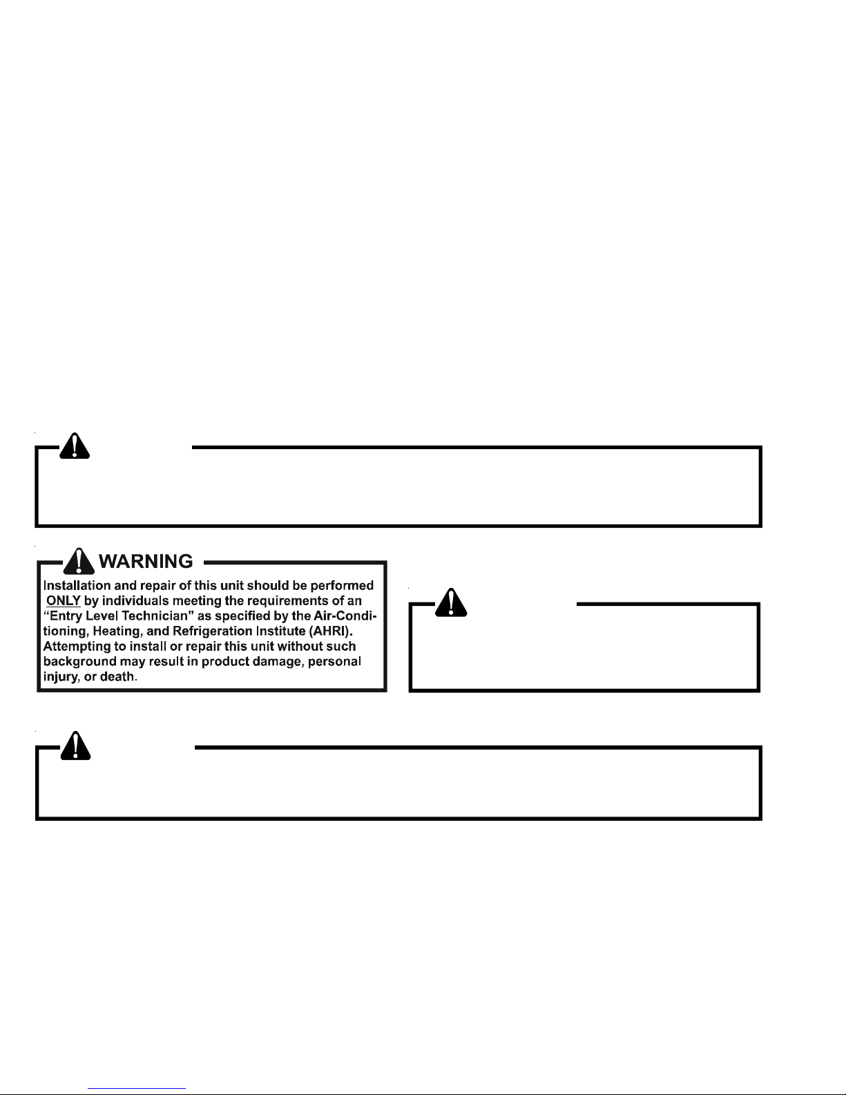
TABLE OF CONTENTS
IMPORTANT INFORMATION .........................2 - 3
MODEL IDENTIFICATION............................4 - 15
AIR HANDLER/COIL IDENTIFICATION ............15
ACCESSORIES......................................... 16 - 20
PRODUCT DESIGN ................................. 21 - 22
SYSTEM OPERATION ..............................23 - 27
TROUBLESHOOTING CHART .........................28
SERVICING TABLE OF CONTENTS ................29
SERVICING .................................................30 - 60
ACCESSORIES WIRING DIAGRAMS ........61 - 69
IMPORTANT INFORMATION
Pride and workmanship go into every product to provide our customers with quality products. It is possible, however,
that during its lifetime a product may require service. Products should be serviced only by a qualified service technician
who is familiar with the safety procedures required in the repair and who is equipped with the proper tools, parts, testing
instruments and the appropriate service manual. REVIEW ALL SERVICE INFORMATION IN THE APPROPRIATE
SERVICE MANUAL BEFORE BEGINNING REPAIRS.
IMPORTANT NOTICES FOR CONSUMERS AND SERVICERS
RECOGNIZE SAFETY SYMBOLS, WORDS AND LABELS
WARNING
This unit should not be connected to, or used in conjunction with, any devices that are not design certified for use with
this unit or have not been tested and approved by Goodman. Serious property damage or personal injury, reduced unit
performance and/or hazardous conditions may result from the use of devices that have not been approved or certified by
Goodman.
WARNING
To prevent the risk of property damage, personal
injury, or death, do not store combustible materials or
use gasoline or other flammable liquids or vapors
in the vicinity of this appliance.
WARNING
Good ma n will not be respo nsible for any injury or prop erty dam age arising from imprope r service or service
procedures. If you perform service o n your own product, you assum e responsibility for any personal inju ry or property
dam age wh ich may result.
To locate an authorized servicer, please consult your telephone book or the dealer from whom you purchased this
product. For further assistance, please contact:
CONSUMER INFORMA TION LINE
GOODMAN® BRAND PRODUCTS
TOLL FREE 1-877-254-4729 (U.S. only)
email us at: customerservice@goodmanmfg.com
fax us at: (713) 856-1821
(Not a technical assistance line for dealers.)
email us at: hac.consumer.affairs@amanahvac.com
CONSUMER INFORMATION LINE
AMANA® BRAND PRODUCTS
TOLL FREE 1-877-254-4729 (U.S. only)
fax us at: (931) 438- 4362
(Not a technical assistance line for dealers.)
Outside the U.S., call 1-713-861-2500. (Not a technical assistance
line for dealers.) Your telephone company will bill you for the call.
2
Outside the U.S., call 1-931-433-6101. (Not a technical assistance
line for dealers.) Your telephone company will bill you for the call.
IMPORTANT INFORMATION
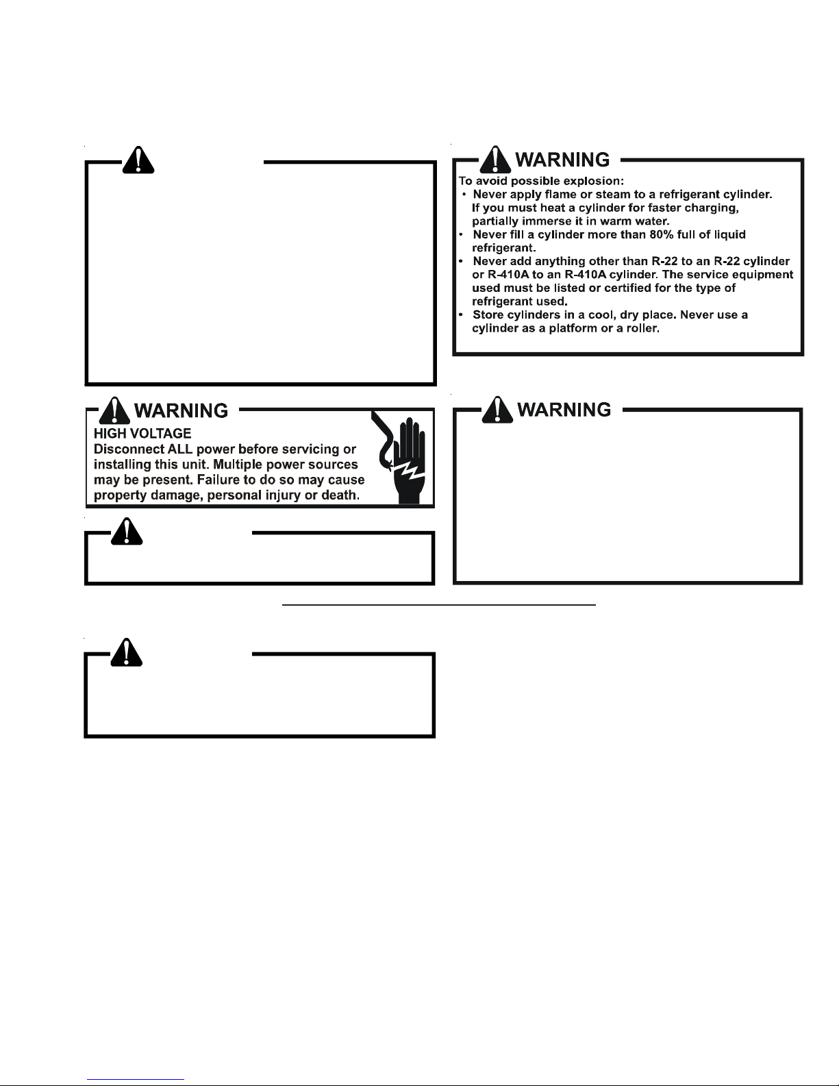
SAFE REFRIGERANT HANDLING
While these items will not cover every conceivable situation, they should serve as a useful guide.
WARNING
Refrige rants are heavier than ai r. T hey can "push out"
the oxygen in your lungs or in any enclosed space.To
avoid possible difficulty in breathing or death:
•
Never purge refrigerant into an enclosed room or
space. By law, all refrigerants must be reclaimed.
•
If an in door leak is suspec ted, t horo ughl y vent ilat e
th e ar ea b ef ore b egi nn i ng w or k.
• Liqui d ref ri ge ra nt can be ver y co l d. To av oi d pos si ble
frostbit e or blind ness , avoi d co ntac t wi th re fri geran t
and wear gloves and goggles. If li quid refrigerant
does cont act your skin or eyes , s eek me dica l hel p
immediate ly.
• Always follow EPA regulations. Never burn refrig erant, as poisonous gas will be produced.
To avoid possible explosion, us e only returnable (not
disposable) service cylinders when removing refrigerant from a s yst em.
• Ensure the cy linder is free of damage which could
lead to a leak or explosion.
• Ensure the hydrostatic test date does no t exceed
WARNING
To avoid possible injury, explosion or death, practice
safe handling of refrigerants.
5 years.
• Ensure the pressure rating meets or exceeds 400
lbs.
When in doubt, do not use cylinder.
WARNING
System contamina nts, improper se rvice procedure
and/or physical abuse affecting hermetic com pressor
electrical terminals may cause dangerous s ystem
venting.
The successful development of hermetically sealed refrigeration compressors has completely sealed the compressor's
moving parts and electric motor inside a common housing,
minimizing refrigerant leaks and the hazards sometimes
associated with moving belts, pulleys or couplings.
Fundamental to the design of hermetic compressors is a
method whereby electrical current is transmitted to the
compressor motor through terminal conductors which pass
through the compressor housing wall. These terminals are
sealed in a dielectric material which insulates them from the
housing and maintains the pressure tight integrity of the
hermetic compressor. The terminals and their dielectric
embedment are strongly constructed, but are vulnerable to
careless compressor installation or maintenance procedures and equally vulnerable to internal electrical short
circuits caused by excessive system contaminants.
In either of these instances, an electrical short between the
terminal and the compressor housing may result in the loss
of integrity between the terminal and its dielectric embedment. This loss may cause the terminals to be expelled,
thereby venting the vaporous and liquid contents of the
compressor housing and system.
A venting compressor terminal normally presents no danger
to anyone, providing the terminal protective cover is properly
in place.
If, however, the terminal protective cover is not properly in
place, a venting terminal may discharge a combination of
(a ) hot lubricating oil and refrigerant
(b ) flammable mixture (if system is contaminated
with air)
in a stream of spray which may be dangerous to anyone in the
vicinity. Death or serious bodily injury could occur.
Under no circumstances is a hermetic compressor to be
electrically energized and/or operated without having the
terminal protective cover properly in place.
See Service Section S-17 for proper servicing.
3
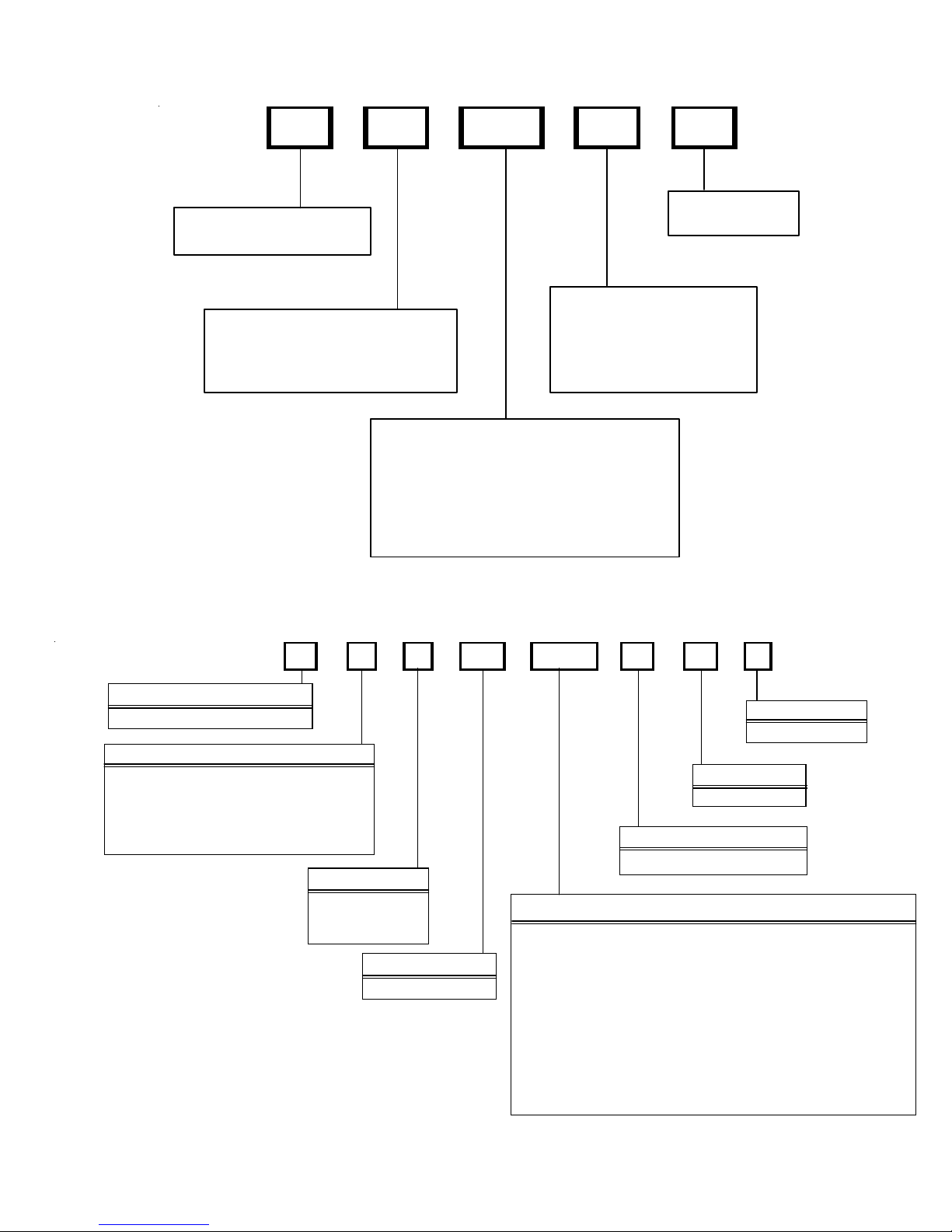
PRODUCT IDENTIFICATION
Split System Air Conditioners R-22
Model # Description
GSC13018-241AA
GSC13036-481AA
GSC1 303 6,48*AA
GSC130**1AB
GSC1 303 6,48*AB
GSC1 3048* AC
GSC13018- 30AC
GSC1301 8,24, 301AD
GS C1300421AC, 484AC
GS C1 3018 , 24, 301 A E
GSC130 48 1, 48 3 AE/A F
GSC130363AE/AF
GSC130361DE/DD
o odman® Br and Split Co ndenser 13 Seer condensi ng units . Init ial release . 26 " chassis
G
G
o odman® Br and Split Co ndenser 13 Seer condensi ng units . Init ial release . 29 " chassis
o odman® Br and Split Co ndenser 13 S eer co ndensing units.
G
Introduce s new 13 SEER AC 3 P H R- 22 Goodm an M odels
G
o odman® Br and Split Co ndenser 13 S eer co ndensing units. Move locat ion of screw
hole.
o odman® Br and Split Co ndenser 13 S eer co ndensing units. Int r oduces new models
G
due to the replacement of 8-pole fan motors with 6-pole.
G
o odman® Br and Split Co ndenser 13 S eer co ndensing units. Move locat ion of screw
hole.
o odman® Br and Split Co ndenser 13 S eer co ndensing units. Release M odels
G
contai ning the br oad oc ean motor 0131M00 06 0
G
o odman® Br and Split Co ndenser 13 S eer co ndensing units. Remo v e 1 hairpin from
coil.
o odman® Br and Split Co ndenser 13 S eer co ndensing units. Release Models contain
GSC1 3048* AD
GSC130481AG
GSC130181BA
GSC130361BA
GSC130361BA
GSC130361BB
GSC130361DF
GSC13024-301CA
GSC130241DA
GSC13036 1FA
GSC130363BA
GSC130301DA
G
the broad ocean motor 0131M 00061
G
o odman® Br and Split Co ndenser 13 S eer co ndensing units. Int r oduces new models
with Bristol compressors.
o odman® Br and Split Co ndenser 13 Seer condensi ng units . Co nver s ion of existin g
G
mod e ls us i ng 3/ 8" dia m e t er tube c oi ls t o 5 mm c o il s.
G
o odman® Br and Split Co ndenser 13 Seer condensi ng units . Init ial release . 35 "
chassis.
o odman® Br and Split Co ndenser 13 S eer co ndensing units. Release M odel wi th
G
Cop eland Scr oll Compressor .
G
o odman® Br and Split Co ndenser 13 S eer co ndensing units. Int r oduces new models
due to the replacement of 8-pole fan motors with 6-pole.
o odman® Br and Split Co ndenser 13 S eer co ndensing units. Int r oduces new models
G
with Bristol compressors.
G
o odman® Br and Split Co ndenser 13 S eer co ndensing units. Int r oduces mo dels wit h
reduced chas sis size from the cur rent 29x3 2.5 to 26x32
o odman® Br and Split Co ndenser 13 S eer co ndensing units. Release of Goodman 13
G
SEER Condensers, with 5 mm coils; compressor change:CR18K7-PFV-230; reduced
refrigerant charge.
o odman® Br and Split Co ndenser 13 Seer condensi ng units . Co nver t s from 3/ 8" to
G
5mm. 2.5 & 3 to n units hav e new coil sl ab height and ne w lo uv er panels . 2.5 - sma ll
chas s is; 3 ton medium chassis.
4
PRODUCT IDENTIFICATION
Split System Air Conditioners R-22
M ode l # Des c ri ptio n
o odm an® Br and Split Condenser 14 Seer condensing units. Intr oduces Goodman®
GSC14 0**1AA
GSC14 0**1AB
GSC140**1AC
GSC140**1AD
GSC14018-421BA
G
Brand 1 4 Seer AC R-2 2 models.
G
o odm an® Br and Split Condenser 14 Seer condensing units. New rev isions hav e screw
locations m ov ed in the top pa nel, bas e pans, l ouv ers , an d c ont r ol b ox c ov er s .
o odm an® Br and Split Condenser 14 Seer condensing units. Relea se models
G
cont aining th e B ro ad Ocea n m otor 013 1 M00060 and 0131M000 61
G
o odm an® Br and Split Condenser 14 Seer condensing units. Revise c ondenser coils by
remov ing (1) hairpin. Reducing r efrigerant quanti ties by 6 ounces.
o odm an® Br and Split Condenser 14 Seer condensing units. Conver s ion of existing
G
models using 3/8" d iameter tube coils to 5 mm coils.
Split System Air Conditioners R-22
M ode l # Des c ri ptio n
A
ASC130**1AA
ASC130**1AB
ASC130**1AC
ASC1301**1AD
ASC130601BD
mana® Brand Split Condenser 13 Seer condensing units. Initial release new models of
Amana® Brand Deluxe 13 S eer AC R-22 c onditioners.
mana® Brand Split Condenser 13 Seer condensing units. Move location of screw hole.
A
A
mana® Brand Split Condenser 13 Seer condensing units. Introduces horizontal style
louvers.
mana® Br and Split Co ndenser 13 Se er condensing unit s . Re mo v e 1 hairpin fro m coil.
A
Sp ec ial Hi gh Fe atu re S p lit X Co nd en ser 14 See r conde ns in g uni t s.
hai rpin fr om coil. Reduce refrigerant quantities by 6 ounces.
Split System Air Conditioners R-22
M ode l # Des c ri ptio n
V
VSC13018-601AA
alue Split Condenser 13 Seer condensing units. Introduces Value 13 Seer AC R-22
models. 2 year part & 5 y ear com pressor warra nty in B ahama Bei ge.
. Remove 1
5
PRODUCT IDENTIFICATION
Split System Heat Pumps R-22
M ode l # De sc r iption
GSH10***AA
GSH10***AB
GSH13***AA
GSH13**1AB
GSH13**1AC
GSH13036-48*AD
GSH13018-301BA
GSH130421AE
o odm an® Brand Sp lit Hea t Pum p 10 Se er heat pump units. Initial releas e.
G
o odm an® Brand Spl it Heat P um p 10 S eer heat pump unit s. S c rew location s
G
mov ed in th e to p panel, ba se pans, lo uv er s , and co ntrol box cov er s . .
o odm an® Brand Sp lit Hea t Pum p 13 Se er heat pump units. Initial releas e.
G
o odm an® Brand Spl it Heat P um p 13 S eer heat pump unit s. Revis ion
G
intr oduces the f ollowing new models due to the rep lacement of 8-pole fa n mo to r s
wi th 6-pole and screw locations mov ed in t he t op panel, bas e pans, l ouv ers , an d
control box covers.
o odm an® Brand Spl it Heat P um p 13 S eer heat pump unit s. Cont ain Broad
G
Oce an m otors S c re w locat ions moved in the top pane l, base pans, louvers, and
control box covers. .
G
o odm an® Brand Spl it Heat P um p 13 S eer heat pump unit s. I ntroduces m odels
that contain the broad ocean motor
o odm an® Brand Spl it Heat P um p 13 S eer heat pump unit s. Reducti on in
G
chass is size from medium to smal l.
o odm an® Brand Spl it Heat P um p 13 S eer heat pump unit s. Repl a ces V 10
G
rever s ing valve with V 6 r ev er sing v alve.
GSH13048*AG
GSH13036*BA/BB
GSH140**1AA
GSH140**1AB
GSH1 40* *1AC
GSH140361AF,
GSH140421-48AD
GSH140601AE
o odm an® Brand Spl it Heat P um p 13 S eer heat pump unit s. I ntroduces
G
model with Bristol Compressors.
G
o odm an® Brand Spl it Heat P um p 13 S eer heat pump unit s. I m pr ov ements to
increase MOP values on 3 ton units.
o odm an® Brand Spl it Heat P um p 14 S eer heat pump unit s. I nitial re lease.
G
G
o odm an® Brand Spl it Heat P um p 14 S eer heat pump unit s. S c rew location s
mov ed in th e to p panel, ba se pans, lo uv er s , and co ntrol box cov er s .
o odm an® Brand Spl it Heat P um p 14 S eer heat pump unit s. Releases
G
models wit h the Broad Ocean mot or .
G
o odm an® Brand Spl it Heat P um p 14 S eer heat pump unit s. Releases
models tha t replace TXV & co mp ens ato r with flowrator & ac cu mulator.
6
PRODUCT IDENTIFICATION
Split System Heat Pump s R-22
Model # D e scr ip t ion
A
ASH130**1AA
ASH130**1AB
ASH130**1AC
Model # D e scr ip t ion
VSH13 18-601AA
mana® Bran d Split Heat Pump 13 Seer heat pump units. Initial release new
mode ls of Amana® Br and D e lux e 13 S eer R-22 heat pum ps .
mana® Bran d Split Heat Pump 13 Seer heat pump units. New revisions have
A
scr ew locations moved in the top panel, b ase pans, louvers, an d cont rol box
covers.
A
mana® Bran d Split Heat Pump 13 Seer heat pump units. New revisions have
horizon tal style louv ers.
Split System Heat Pump s R-22
V
alue Split He at Pump 13 Seer h eat pum p units . Introd uc es Value 13 Se er HP R-
22 mode ls. 2 year parts & 5 ye ar compressor wa rranty i n Bahama Beige.
7
PRODUCT IDENTIFICATION
Single Piec e Air Ha ndl e r s
Model # Description
Singl e P i ec e R Multi-Position PSC Motor Unpainte d Flowrater Introduc t i on of new 13
ARUF****16AA
ARUF364216AB
ARUF486016AB
ARUF364216AC
ARUF****16BA
ARUF****1BA
A
SE E R A i r Handler Model s. All M odel s will be suitable for us e with R-22 and R-410A
Singl e P i ec e R Multi-Position PSC Motor Unpainte d Flowrater. Revision replac es the
A
current s pot wel ded blower hous i ng wit h the same cinched or cri m ped des i gn used on
the 80% furnace l i ne.
Singl e P i ec e R Multi-Position PSC Motor Unpainte d Flowrater. Revision replac es the
A
current s pot wel ded blower hous i ng wit h the same cinched or cri m ped des i gn used on
the 80% furnace l i ne.
Singl e P i ec e R Multi-Position PSC Motor Unpainte d Flowrater. Revision replac es the
A
current s pot wel ded blower hous i ng wit h the same cinched or cri m ped des i gn used on
the 80% furnace l i ne.
Singl e P i ec e R Multi-Position PSC Motor Unpainte d Flowrater. Revi s i on replaces all
A
ARUFc oi l s using wavy fin wit h l ouver enhanced fin.
Singl e P i ec e R Multi-Position PSC Motor Unpainte d Flowrater Introduc at i on of R-22
A
Only A i r Handlers .
ARPF****16AA
ARPF364216AB
ARPF486016AB
ARPF****16BA
ARPF****1BA
ADPF****16AA
ADPF364216AB
ADPF486016AB
Singl e P i ec e R Multi-Position PSC Motor Painted Flowrater Introduc at i on of new 13
A
SE E R A i r Handler Model s. All M odel s will be suitable for us e with R-22 and R-410A
Singl e P i ec e R Multi-Position PSC Motor Painted Flowrater. Revision replac es the
A
current s pot wel ded blower hous i ng wit h the same cinched or cri m ped des i gn used on
the 80% furnace l i ne.
Singl e P i ec e R Multi-Position PSC Motor Painted Flowrater. Revision replac es the
A
current s pot wel ded blower hous i ng wit h the same cinched or cri m ped des i gn used on
the 80% furnace l i ne.
Singl e P i ec e R Multi-Position PSC Motor Painted Flowrater. Revision replac es all
A
ARPF coils using wavy fin with louver enhanced fin.
Singl e P i ec e R Multi-Position PSC Motor Painted Flowrater. Introduc ation of R-22
A
Only A i r Handlers .
Singl e P i ec e Downflow PSC Mot or Unpainted Flowrater. Introduc at i on of new 13
A
SE E R A i r Handler Model s. All M odel s will be suitable for us e with R-22 and R-410A
Singl e P i ec e Downflow PSC Mot or Unpainted Flowrater. Revi s i on replaces the current
A
spot wel ded blower hous i ng wit h the same c i nched or crimped des i gn us ed on t he 80%
furnace line.
Singl e P i ec e Downflow PSC Mot or Unpainted Flowrater. Revi s i on replaces the current
A
spot wel ded blower hous i ng wit h the same c i nched or crimped des i gn us ed on t he 80%
furnace line.
Singl e P i ec e Downflow PSC Mot or Unpainted Flowrater. Revi s i on replaces the current
A
ADPF304216AC
ADPF****1BA
spot wel ded blower hous i ng wit h the same c i nched or crimped des i gn us ed on t he 80%
furnace line.
Singl e P i ec e Downflow PSC Mot or Unpainted Flowrater Revision replaces all
A
ARPF coils using wavy fin with louver enhanced fin.
8
PRODUCT IDENTIFICATION
-
S ing le Pie ce Air Ha n dl ers
Mode l # Description
Single Piece E Mult i-P os ition Vari able-Speed Painted Flowrator. Introducation of
A
AEPF****16AA
AEPF****16BA
AEPF****16BB
AEPF****16CA
AEPF****1BA
new 13 SE E R Air Handler M odels. A ll M odels w il l be s uitable for us e wit h R- 22 and
R-410A
Single Piece E Mult i-P os ition Vari able-Speed Painted Flowrator. Revision
A
introduces new models add ing low er kw hit ki ts on the S &R plate
Single Piece E Mult i-P os ition Vari able-Speed Painted Flowrator. Revision
A
replaces t he c ur r ent spo t welded blower housing w ith t he same c inch ed o r crimped
design use d on the 80% fu r n ac e l i ne.
A
Single Piece E Mult i-P os ition Vari able-Speed Painted Flowrator. Revision
replaces all ARP Fcoils us i ng wavy fin w ith louver enhanc ed fin.
Single Piece E Mult i-P os ition Vari able-Speed Painted Flowr at or Intr o ducti o n of R
A
22 O nly Air Han dlers.
AEPF313716AA
ASPF313716AA
ASPF****16AA
ASPF****16BA
AWUF****1AA
AWUF****16AA
AWUF3005-101AA
AWUF****1BA
AWUF370**16AA
(ASPF)
(AEPF)
. Introduction of
A
Single Piece E Mult i-P os ition Vari able-Speed Painted Flowrator
Sin gle Piece S Mult i -Position EEM mo tor Painted Flowrator
3-Ton Air Handle r units wi th 3-row co i l.
Single Piece S Multi-Position EEM mot or Painted Flowrator. Introduces new
A
ASPF Air H andlers
Single Piece S Multi-Position EEM mot or Painted Flowrator. Revision introuces
A
modi fied ASPF control scheme, to ensur e blower operation duri ng and after call for
hea t on units wi th heat k it s and r eplacing wav y fi n with louver enhance d fin on coi l
Single Piece Ai r Handler Wal l Mount Unpainted Flo wrator. Introduc es 13 SEER
A
Dayto n wall mount air ha ndlers
Single Piece Ai r Handler Wal l Mount Unpainted Flo wrator. Introduc es 13 SEER
A
Dayton wall mount air handlers. All Models will be suitable for use with R-22 and R410A
Single Piece Ai r Handler Wal l Mount Unpainted Flo wrator. Introduc es 13 SEER
A
Dayton wall moun t air handlers using a Burr Oak Louvered Fin coil.
A
Single Piece Ai r Handler Wal l Mount Unpainted Flowrat o r . Revision replace s
cur r ent wavey fin design wit h new louv ered fin design
Single Piece Ai r Handler Wal l Mount Unpainted Flowrator. Introduction of
A
AWUF37 Air Handl er s for use wit h R- 22 and R410A .
and
A
AWUF****16BA
ACNF****1AA
ACNF****16 AA
ACNF****1BA
AH**-1*
Single Piece Ai r Handler Ceiling Mount N Un ca s ed Flow rater. Rev ision has
A
louv er fins & replaces copper tu be hairpi ns with aluminum hairpins.
A
Single Piece Ai r Handler Ceiling Mount N Un ca s ed Flow rater. Rev ision re lease
all models of 13 SEE R Dayt on u n c ase d ai r handler s.
Single Piece Ai r Handler Ceiling Mount N Un ca s ed Flow rater. Rev ision re lease
A
all models of 13 SEER Dayton u n c as ed air handlers.All M odels w ill be s uitable for
use with R-22 and R-410A
Single Piece Ai r Handler Ceiling Mount N Un ca s ed Flow rater. Rev ision repla c es
A
cur r ent wavey fin design wit h new louv ered fin design
A
Single Piece Ai r Handler Hydronic Air Hand ler. Revision replaces the time dela y
r e lay in the AH a i r ha ndl ers w i th the UTE C t ime del ay co ntr ol bo ard.
9
PRODUCT IDENTIFICATION
A
MBR/MBE Air Handlers
Mo del # Description
odular Blower R Multi- P os iti on P S C M otor. Introduc es module blo wer wit h P S C
MBR****AA-1AA
MBE****AA-1AA
MBE****AA-1BA
Mo del # Description
CAUF*****6AA
CAUF*****6BA
M
b l ower m o t o r .
M
odular Blower E Multi- Pos ition Variable-Speed . I ntrodu c es module blower wit h
variable speed blo wer m ot or .
odular Blower E Multi- Pos ition Variabl e- S peed .Revision in troduces new m odels
M
adding lower kw hit kits on the S&R plate
Evaporator Coils
C
Indoor Coil A Upfl ow/Downflow Uncased Flowrator. In troduces 13 SEER CAUF
Dayton Upflow/Downflow coils.
Indoor Coil A Upfl ow/Downflow Uncased Flo wrator. Revision releases Burr Oak
C
Lou v er ed F in in pl ac e of th e Wavy Fin current ly in pr oducti on.
CAPF*****6AA
CAPF*****6BA
CAPF/CAUF36***CA
CHPF*****6AA
CHPF*****6BA
CHPF1824A6CA
CHPF2430B6CA
CHPF3636B6CA
CHPF3642C6CA
CHPF3642D6CA
CHPF3743C6BA
CHPF3743D6BA
CHPF4860D6D
CSCF*****6AA
Indoor Coil A Upfl ow/Downflow Painted Flowrator. Introduces 13 SEER CAPF
C
Dayton Upflow/Downflow coils.
C
Indoor Coil A Upfl ow/Downflow Painted Flow rator. Rev ision releases Burr Oa k
Lou v er ed F in in pl ac e of th e Wavy Fin current ly in produ c tion.
Indoor Coil A Upfl ow/Downflow [Painted or Uncased] Flowrator. Revision
C
redesigns for pe rfor m ance impr ovement from 2 row to 3 row.
C
Indoor Coil Horizontal A Coil Painte d Flowrator. Release 13 SEER CHPF
horizon tal A coil.
C
Indoor Coil Horizontal A Coil Painte d Flowrator. Release 13 SEER CHPF
horizon tal A coil. Rev is ion rele as es Bur r O ak Louvered Fin in place of the Wavy
Fin c ur rently in product ion. T he rows chang e by one, (i . e. 4 r ow to 3 row; 3 row t o
2 row) where appl ic able.
Indoor Coil Horizontal A Coil Painte d Fl owr ato r . 13 S EER CHPF hor izontal A
C
coil, revision has louver fins & replaces copper tu be hairpins with a luminum
hairpins.
Indoor Coil S Horizontal Slab Coil C Upainted Flowrator. Release 13 SEER
C
CSCF slab hor izontal coil.
Indoor Coil S Horizontal Slab Coil C Upainted Flow rator. Revi sion r eleases Bur r
C
CSCF*****6BA
10
Oak Louvered Fin in place of the Wavy Fin currently in production. The rows
change by one, ( i. e. 4 row to 3 r ow; 3 r ow t o 2 r ow) where app lic able .
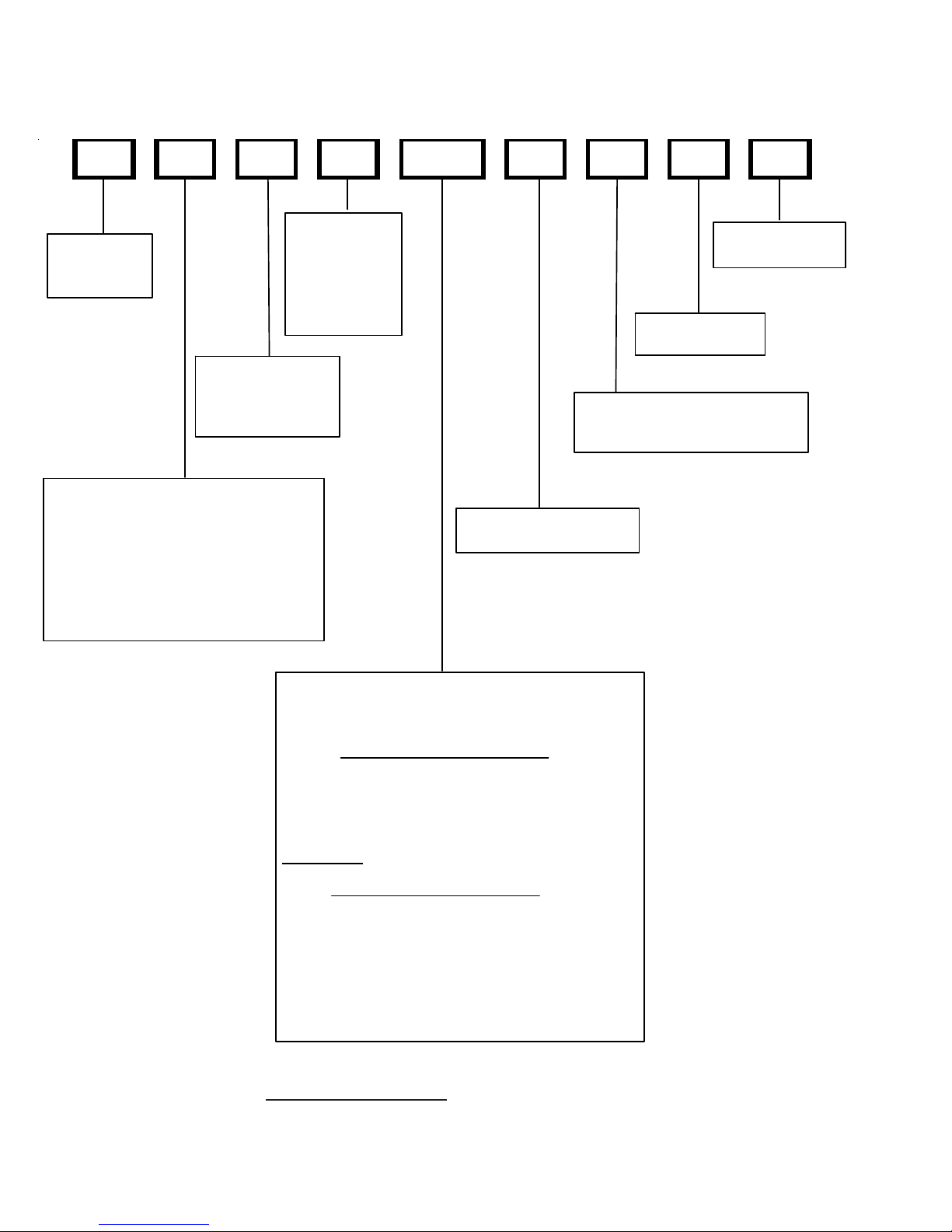
PRODUCT IDENTIFICATION
p
GSC140361AA
BR A ND:
G: Goodm a n
Amana
A: Amana
V: Val ue
®
®
Brand Dist inctio ns
®
Brand
Brand /
PRODU CT
CATE GORY:
S: Split System
UNIT TYPE:
C: Condense r R-22
H: Heat Pum p R-22
SEER:
10 : 10 SE E R
13 : 13 SE E R
14 : 14 SE E R
NOMINAL
CA PACITY :
018: 1.5 Tons
024: 2 Tons
030: 2.5 Tons
036: 3 Tons
042: 3.5 Tons
048: 4 Tons
060: 5 Tons
MINOR
REVIS ION:
A: Initial Releas e
MAJOR
REVISION:
A: I n itial Re lea s e
ELEC TRICAL:
1: 208-230V/1ph/60H z
3: 208-230v/3ph/60H z
4: 460v/3ph/60H z
CPKF036 2 A
PROD UCT CATE GOR Y :
C : Split System
UNIT TYPE:
E: Commercial Air Con ditioner
K: Air Cojd itioner
P: Heat Pum
REVISION:
A: Re vision
ELECT RICAL:
1: 208- 230V/1ph/60Hz
2: 220- 240V/1ph/50 Hz
3: 208-23 0v /3ph/60 Hz
4: 308/415V /3 ph/ 50Hz
NOMINAL CAPACITY:
018: 1 .5 Ton s 048: 4 Tons
024: 2 Tons 060: 5 Tons
030: 2 .5 Ton s 070: 5 Tons
036: 3 Tons 090: 7.5 T ons
042: 3 .5 Ton s 120: 1 0 Tons
11
PRODUCT IDENTIFICATION
p
p
C KF 036 2 A
P R O D UCT CATEGORY :
C : Split Sy s tem
UNIT TYPE:
E: Co m mercial Air Conditioner
K: Air Cojditioner
P: Heat Pum
NOMINAL CAPACITY:
018: 1.5 T ons 048: 4 Tons
024: 2 Tons 060: 5 Tons
030: 2.5 T ons 070: 5 Tons
036: 3 Tons 090: 7.5 T ons
042: 3.5 T ons 120: 1 0 Tons
REVISION:
A: Re vision
ELECTRICAL:
1: 20 8- 230V/1ph/60Hz
2: 22 0- 240V/1ph/50 Hz
3: 20 8- 230v/3ph/60Hz
4: 30 8/415V/3 ph/50Hz
CKL0362A
PRODUC T CATE GO R Y :
C : Split Sys tem
UNIT TYPE:
E: Commercial Air Conditione r
K: Air Cojditioner
P: Heat Pum
REVISION:
A: Revi sion
ELECTRICAL:
1: 20 8-23 0V /1ph/60 Hz
2: 22 0-24 0V /1ph/5 0 Hz
3: 20 8-23 0v /3ph/60 Hz
4: 308/415V/3ph/50Hz
NOMINAL CAP ACITY:
018: 1.5 Tons 04 8: 4 Tons
024: 2 Tons 060: 5 Tons
030: 2.5 Tons 07 0: 5 Tons
036: 3 Tons 090: 7.5 Tons
042: 3.5 Tons 120: 10 Tons
12
PRODUCT IDENTIFICATION
A
A
A
A
A
A
p
C E 120 5 A
PRODUCT CATEGOR Y:
C : Split Syst em
UNIT TYPE:
E: Comm ercial Air Conditioner
K: Air Cojdit ioner
P: Heat Pum
N OMINA L CAPACI TY:
018: 1.5 Tons 048: 4 Tons
024: 2 Tons 060: 5 Tons
030: 2.5 Tons 070: 5 Tons
036: 3 Tons 090: 7.5 Tons
042: 3.5 Tons 120: 10 Tons
REVISION :
A: Revision
ELECTRICAL:
1: 208-230V/1ph/60Hz
2: 220-240V/1ph/50 Hz
3: 208-230v/3ph/60Hz
4: 308/ 415V /3ph /50Hz
THIS NOMENCLATURE IS TO BE USED TRHOUGH JULY 2006
R U F 3642 1
Product Type
: Single Piece Air Handler
Application
C: Ceiling Mo un t P S C Mo to r
D: Downflow PSC Motor
E: Multi-Position Variable Speed Motor
R: Multi-Position PSC Motor
W: Wall Mount PSC Motor
Cabinet Finish
U: Unpainted
P: Painted
N: Uncased
Expansion Device
F: Flowrater
Nominal Capacity Range @ 13 SEER
Multi-Position & Downflow Applications
3642: 3 - 3 1/2 tons
1830: 1 1/2 - 3 1/2 tons
1729: 1 1/2 - 2 1/2 Tons 10 SEER (for export systems)
Ceiling Mount & Wall Mount Applications
1805: Nominal Cool ing Capacity
Electric Heat kw - 1 1/2 tons Cooling/5 kw Electric Heat
2405: Nominal Cool ing Capacity
Electric Heat kw - 2 Tons Cooling/5 kw Electric Heat
3608: Nominal Cool ing Capacity
Electric Heat kw - 3 Tons Cooling/8 kw Electric Heat
Minor Revisi on
: Initial Release
Major Revision
: Initial Release
Electrical
1: 208/230V, 1 Phase, 60 Hz
13
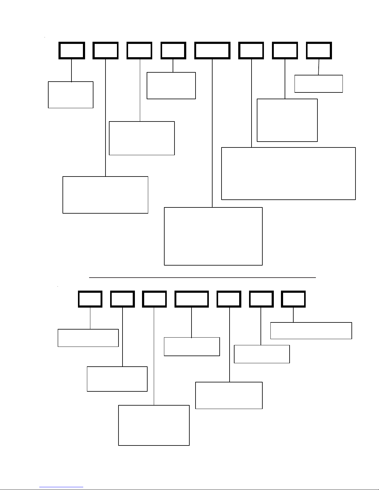
PRODUCT IDENTIFICATION
THIS NOMENCLATURE IS TO BE USED AFTER JULY 2006
A W U F 3642 1 6 A A
EXP ANSION
PRODUCT
TYPE:
A: Air Han dler
CABINE T FINISH:
U: U npainted
P: Pa ited
N: Uncased
APPLICATION
C: Ceiling Mount PSC M otor
D: Downflow PSC Motor
E: Mul ti-Position Varible-Speed Motor
S: Energy-Efficient Mo tor
R: Multi-Position PSC Motor
T: Coated Coils
W: Wall M o unt PS C Motor
DEVICE:
F: Flowrater
T: TXV
(Expansion
Device)
MINOR
R EVISION*
MAJOR
REVISION*
R EFRIG ERANT C H ARG E:
No Digit: R-22 Only
6 : R-410A or R-22
ELECTRICA L:
1: 208-230V/1ph/60Hz
NOMINA L CAPA CITY RANGE:
@ 13 SEER
Dedicat ed Application
36 36: 3 T o ns
Multi-Posit ion & Dow nfl ow A ppli cations
31 37: 3 T o ns
3642: 3 - 3 1/2 Tons
1830: 1 1/2 - 3 1/2 Tons
@10 S E E R
1729: 1 1/2 - 2 1/2 Tons (for expo r t sys tems)
Ceiling Mount & Wall Mount Applications
(Nominal Cooling Capacity/Ele c tric Heat kW)
1805: 1 1/2 Tons Cooling / 5 kW Electric Heat
2 4 05: 2 Tons Co o lin g / 5 k W Ele ctr i c He at
3 6 08: 3 Tons Co o lin g / 8 k W Ele ctr i c He at
3 7 05: 3 Tons Co o lin g / 5 k W Ele ctr i c He at
3 7 08: 3 Tons Co o lin g / 8 k W Ele ctr i c He at
All Airhandlers use DIRECT DRIVE MOTORS. Power supply is AC 208-230v, 60 hz, 1 phase.
14
PRODUCT IDENTIFICATION
r
C A P F 1824 A 6 A
PRODUCT
TYPE:
C: Indoor Coil
A PPLICATION
A: U pfl ow /Downflo w Coil
H: Horizontal A Coil
S: Horizontal Slab Coil
EXPANSION
DEVICE:
F: Flowrate
CAB INE T FINIS H:
U: Unpai n t ed
P: Pai nted
N: Unp ainted Case
REVISION
A: Revision
REFRIGERANT
CHARGE:
6: R-410A or R-22
2: R- 22
4: R- 41 0a
NOMINAL WIDT H FOR GAS F URNAC E
A : Fits 14" Furnace Cabinet
B: Fits 17 1/2" Furnace Cabinet
C: Fits 21" Fu r nac e C abi ne t
D: Fits 24 1/2" Furnace Cabinet
N: Does Not Apply ( Hor izontal Slab Coils)
NOMINAL CAPACITY RANGE
@ 13 SEER
18 24 : 1 1/2 to 2 T on s
30 30 : 2 1/2 To ns
36 36 : 3 Ton s
3642: 3 to 3 1/2 T ons
48 60 : 4 & 5 Ton s
MB R 8 00 A A 1
DESIGN SERIES:
MB: Modular Blower
MOTOR TYPE:
R: Consta nt Speed
E: Variable Speed
FACTORY HE AT
0 0: No Heat
AIRFLOW DE LI V E RE D
08: 800 CFM
12: 1200 CFM
16: 1600 CFM
20: 2000 CFM
ELECTRI CA L SUPPLY:
1 : 208-23 0V /60hZ/1 ph
DESIGN SERI ES
A: First Series
CIRCUIT BREAKER
A : No Cir c uit B r eak er
B: C irc uit B rea k er
MODEL MFG. #
MBR0800 MBR0800
MBR1200 MBR1200
MBR1600 MBR1600
MBR2000 MBR2000
MBE1200 MBE1200
MBE1600 MBE1600
MBE2000 MBE2000
15
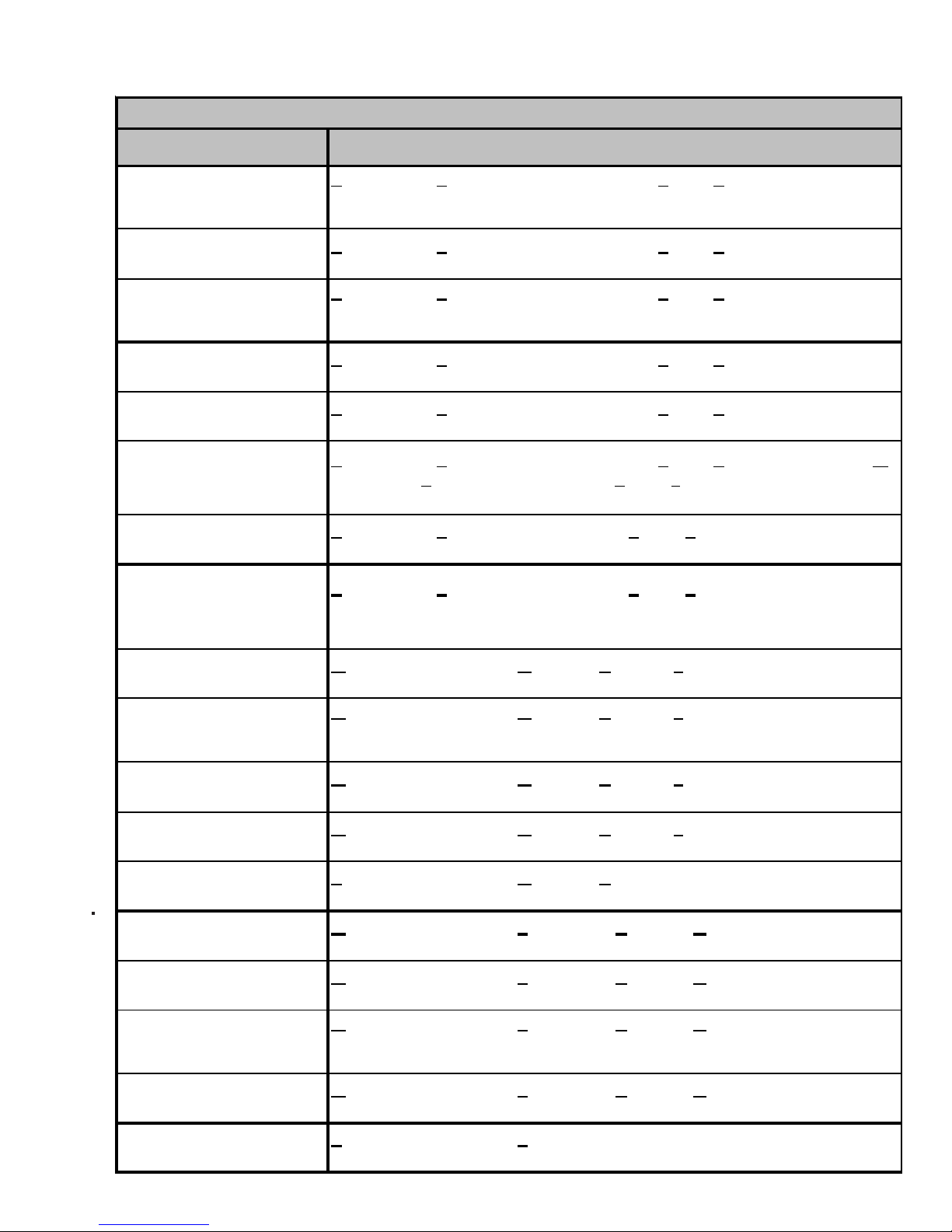
ACCESSORIES
X X X
X X
X X
t
X X X
X X
X X X
t
X X
A
t
X X X
X X
Mo del
AFE18-60A
OT18-60A
FSK01A*
ASC01
TX2N2*
TX3N2*
TX5N2*
OT18-60A
OT/EHR18-60
CSR-U-1
CSR-U-2
CSR-U-3
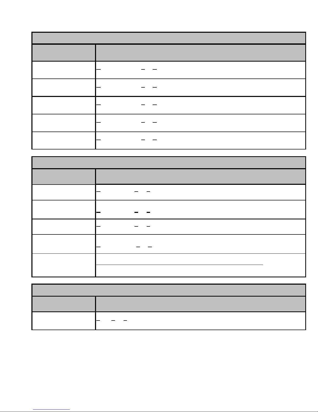
Descript ion G/ VSH13018 G /VSH13024 G/VSH 1 3030 G /VSH 13 036 G/VSH13042 G/VSH13048 G/VSH13060
All Fuel Kit
Outdoor Thermostat
Freeze Pr ote ct ion Ki t
Anti Short Cycle Kit
TXV Kit
TXV Kit
TXV Kit
Outdoor Lockout Stat
Emer ge ncy H eat relay kit
Hard Start Kit
Hard Start Kit
Hard Start Kit
X
X
X
X
X
X
X
X
X
X
X
X
X
X
X
X
X
X
X
x --- --- --- --- --- --x X
X
--- --- --- ---
X
X
X
X
X
X
X
X
X
--- --- ---
--- --- --- --- ---
X
X
X
X
X
--- --- ---
X
X
X
X
X
X
--- --- ---
X
X
X
X
X
X
X
X
X
X
Mo del
AFE18-60A
OT18-60A
FSK01A*
ASC01
TX2N2*
TX3N2*
TX5N2*
OT18-60A
OT/EHR18-60
CSR-U-1
CSR-U-2
CSR-U-3
Model
OT18-60A
FSK01A*
ASC01
TX2N2*
TX3N2*
TX5N2*
CSR-U-1
CSR-U-2
CSR-U-3
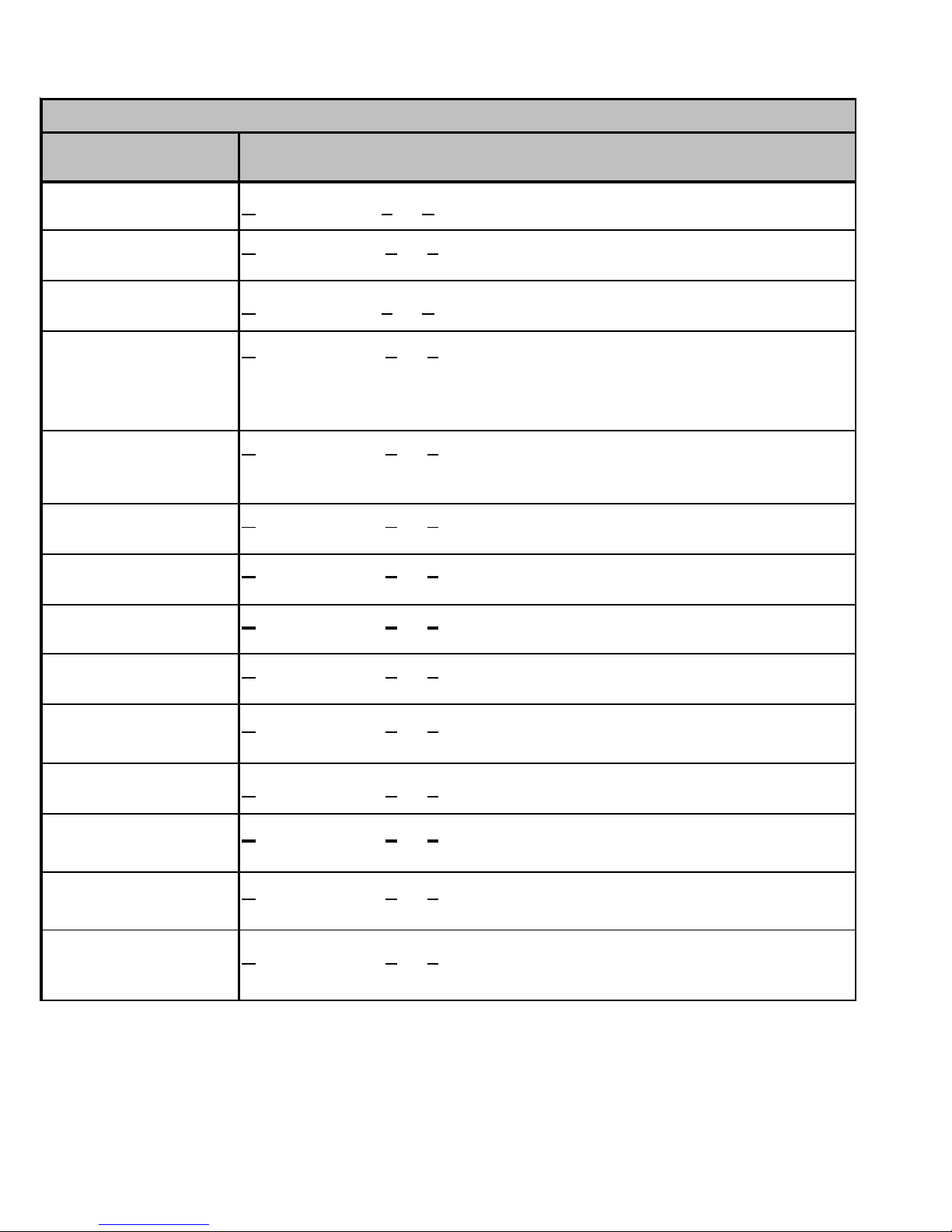
Descr iption A SH13018 ASH1 3024 ASH13030 ASH13036 AS H13042 A SH 13048 ASH13060
All Fuel Kit
Outdoor Thermosta
Freeze Pr ote ct ion Ki t
Anti Short Cycle Kit
TXV Kit
TXV Kit
TXV Kit
Outdoor Lockout Stat
Emer ge ncy H eat relay kit
Hard Start Kit
Hard Start Kit
Hard Start Kit
Description ASC 13018 ASC13024 ASC13030 ASC13036 ASC13042 AS C 13 048 ASC13060
Outdoor Thermosta
Freeze Pr ote ct ion Ki t
Anti Short Cycle Kit
TXV Kit
TXV Kit
TXV Kit
Hard Start Kit
Hard Start Kit
Hard Start Kit
X
X
X
X
X
X
X
X
X
X
X
X
X
X
X
X
X
X
X
x --- --- --- --- --- --x X
X
--- --- --- ---
X
X
X
X
X
X
--- --- ---
--- --- --- --- ---
X
X
X
X
X
--- --- ---
X
X
X
X
X
X
--- --- ---
X
X
X
--- --- --- --- --- --- ---
X
X
X
X
X
X
X
X
X
X
X
X
X
--- --- --- --- --- ---
x x x x --- --- ---
--- --- --- ---
X
--- --- ---
X
X
X
X
--- --- ---
--- --- --- --- ---
X
X
X
X
X
X
X
X
X
X
X
X
X
X
X
X
X
Model
OT18-60A
FSK01A*
ASC01
TX2N2*
TX3N2*
TX5N2*
CSR-U-1
CSR-U-2
CSR-U-3
Model Description GSC100903 GSC100904 GSC101203 GSC101204
FSK01A*
ASC01
OT/EHR18-60
Model Description GSH100903 GSH100904 GSH101203 GSH101204
FSK01A*
ASC01
OT/EHR18-60
Descript ion G/ VSC13018 G /VSC13024 G/VSC 1 3030 G /VSC 13 036 G/VSC13042 G/VSC13048 G/VSC13060
Outdoor Thermostat
Freeze Pr ote ct ion Ki t
nti Short Cycle Ki
TXV Kit
TXV Kit
TXV Kit
Hard Start Kit
Hard Start Kit
Hard Start Kit
Freeze Pr ote ct ion Ki t
Anti Short Cycle Kit
Emer ge ncy H eat relay kit
Freeze Pr ote ct ion Ki t
Anti Short Cycle Kit
Emer ge ncy H eat relay kit
16
--- --- --- --- --- --- ---
X
X
X
X
X
X
X
X
--- --- --- --- --- ---
x x x x --- --- ---
--- --- --- ---
X
--- --- ---
X
X
X
X
--- --- ---
--- --- --- --- ---
X
X
X
X
X
xxxx
xxxx
--- --- --- ---
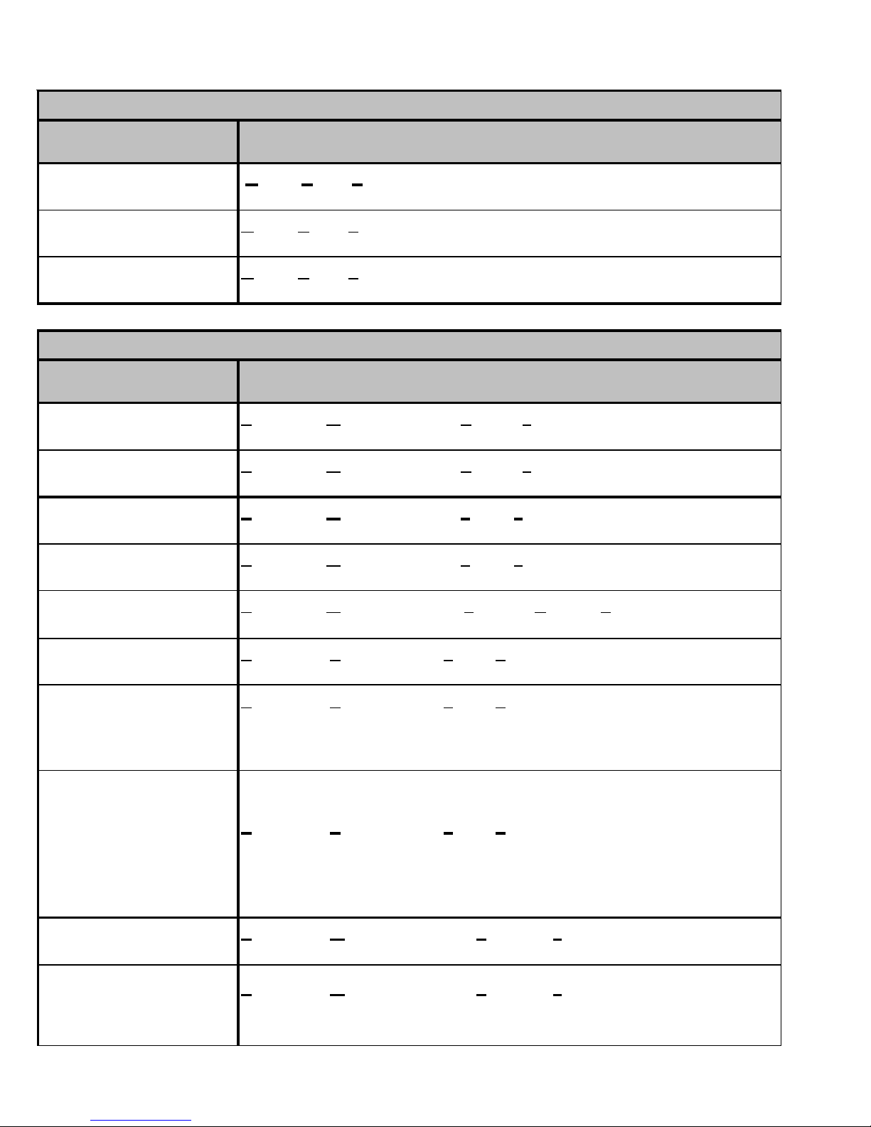
*Installed on indoor coil.
xxxx
xxxx
--- --- --- ---
X
X
X
X
X
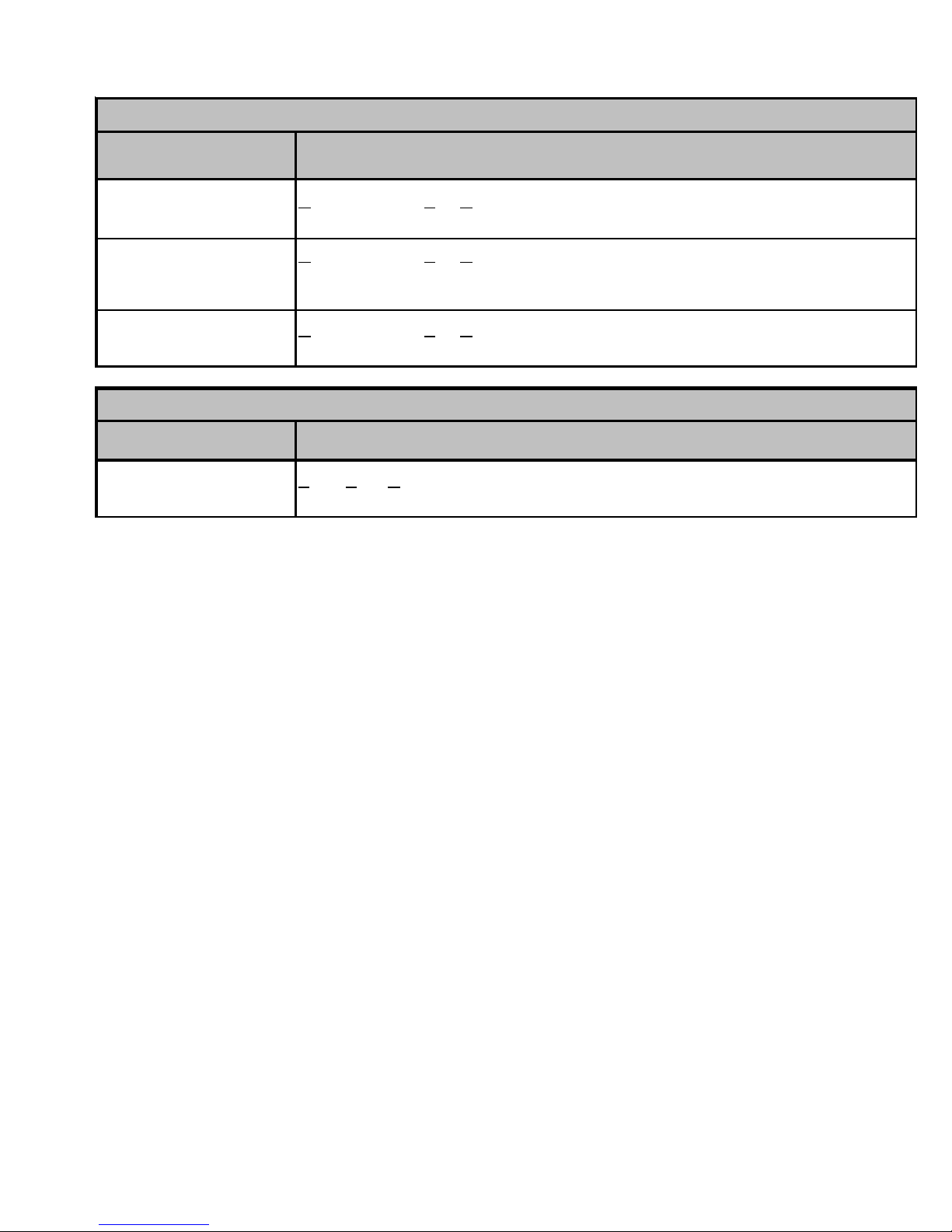
ACCESSORIES
Model
AFE18-60A
OT18-60A
FSK01A*
ASC01
TX2N2*
TX3N2*
TX5N2*
OT18-60A Outdoor Lockout Stat
OT/EHR18-60
CSR-U-1 Hard Start Kit
CSR-U-2
CSR-U-3 Hard Start Kit
Description
All Fuel Kit
Outdoor Thermostat
Freeze Protection Kit
Anti Short Cycle Kit
TXV Kit
TXV Kit
TXV Kit
Emergency Heat relay kit
Hard Start Kit
CPKF24 CPKF36 CPKF42 CPKF48 CPKF60 CPKF61
xxxxxx
xxxxxx
xxxxxx
xxxxxx
--- --- --- --- --- --x x --- --- --- ---
--- ---
xxxx
xxxxxx
xxxxxx
x x --- --- --- ---
---xxxxx
--- --- --- x x x
Model
AFE18-60A
OT18-60A
FSK01A* Freeze Protection Kit
ASC01
TX2N2*
TX3N2*
TX5N2*
OT18-60A
OT/EHR18-60
CSR-U-1
CSR-U-2
CSR-U-3
Model
AFE18-60A
OT18-60A
FSK01A*
ASC01
TX2N2*
TX3N2*
TX5N2*
OT18-60A
OT/EHR18-60
CSR-U-1
CSR-U-2
CSR-U-3
Description
All Fuel Kit
Outdoor Thermostat
Anti Short Cycle Kit
TXV Kit
TXV Kit
TXV Kit
Outdoor Lockout Stat
Emergency Heat relay kit
Hard Start Kit
Hard Start Kit
Hard Start Kit
Description
All Fuel Kit
Outdoor Thermostat
Freeze Protection Kit
Anti Short Cycle Kit
TXV Kit
TXV Kit
TXV Kit
Outdoor Lockout Stat
Emergency Heat relay kit
Hard Start Kit
Hard Start Kit
Hard Start Kit
CKF24 CKF36 CKF48 CKF60 CKF70
--- --- --- --- ---
--- --- --- --- --xxxxx
xxxxx
--- --- --- --- --x x --- --- ---
--- ---
xx
---
--- --- --- --- ---
--- --- --- --- --x x --- --- ---
--- x x x ---
--- --- x x ---
CKL18 CKL24 CKL30 CKL36 CKL42 CKL49 CKL60
--- --- --- --- --- --- ---
--- --- --- --- --- --- --xxxxxxx
xxxxxxx
x --- --- --- --- --- --xxxx---------
--- --- --- --- x x x
--- --- --- --- --- --- ---
--- --- --- --- --- --- --xxxx---------
--- --- --- x x x x
--- --- --- --- --- x x
Model
AFE18-60A
OT18-60A
FSK01A*
ASC01
TX2N2*
TX3N2*
TX5N2*
OT18-60A
OT/EHR18-60
CSR-U-1
CSR-U-2
CSR-U-3
Description
All Fuel Kit
Outdoor Thermostat
Freeze Protection Kit
Anti Short Cycle Kit
TXV Kit
TXV Kit
TXV Kit
Outdoor Lockout Stat
Emergency Heat relay kit
Hard Start Kit
Hard Start Kit
Hard Start Kit
CE120
---
--x
x
---
---
---
---
---
---
---
---
17
ACCESSORIES
A
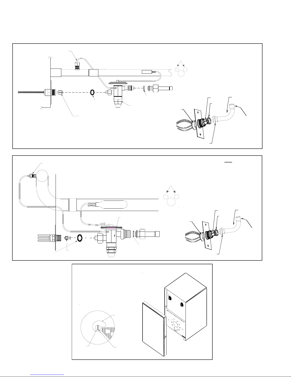
EXP ANSION VALVE KITS
1/4 FLARE CONNECTION
BULB TO BE LOCATED
AT 10 OR 2 O'CLOCK
For Applications requiring
a field installed access fitting
EVAPORATOR COIL
EVAPORATOR COIL
1/4' FLARE
CONNECTION
SEAL SUPP L IE D W/ KIT
REMOVE BEFORE INSTALLI NG EXP ANS IO N VALVE
SUCTION LINE
BULB
EXPANSION VALVE
SUCTION LINE
EXPAN SION VALVE
BULB
SEAL SUPPLIED W/ KIT
BULB TO BE LOCATED
AT 10 OR 2 O'CLOCK
DISTRIBUTOR
BODY
For Applications not requiring
a field installed access fitting
DISTRIBUTOR
BODY
7/8" NUT
PISTON
SEAL
PISTON
SEAL
TAILPIECE
3/8"SWEAT
TAILPIECE
3/8"SWEAT
REMOVE BEFORE
SEAL SUPPLIED W/ KIT
INSTALLING
EXPANSION VALVE
OUTDOOR THERMOSTAT &
EMERGENCY HEAT RELAY
315º
Set Point
djustmen t
Screw
18
SEAL SUPPLIED W/ KIT
OT/EHR18-60
OT18-60
Thermostat
Dial
(Turn Clockwise)
COLD
DEAD
DIAL
45º
WARM
Set Point
Indicato r
Mark
(Shown @ Oº F)
(Turn Counterclockwise)
7/8" NUT
ACCESSORIES
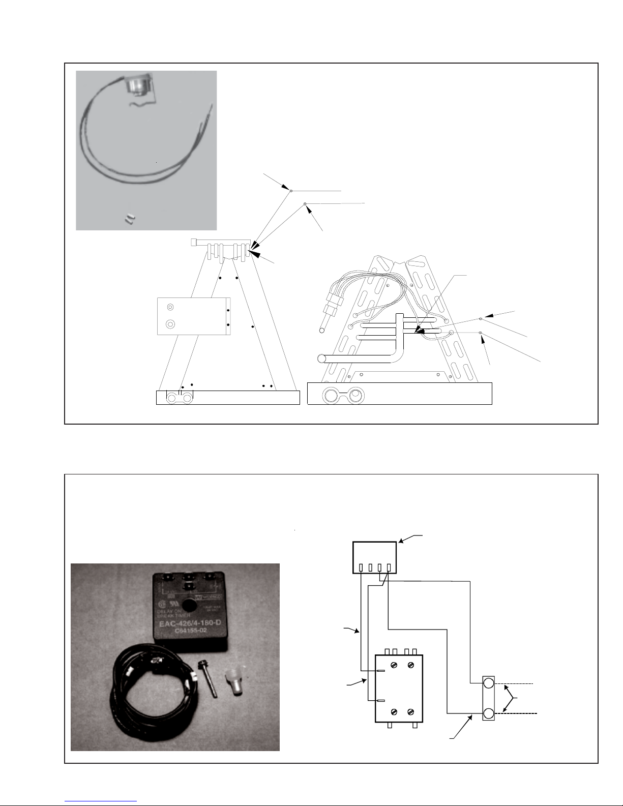
Y
Wire Nut
FSK01A
FREEZE THERMOSTAT
KIT
Y
k
c
a
l
B
k
c
a
l
B
Wire Nut
Y
Install L ine
Thermostat
Here
ASC01A
ANTI-SHORT -CYCLE CONTROL KIT
Y1Y2R1
R2
Install Line
Thermostat
Wire Nut
SHOR T CYCLE
PROTECTOR
Here
B
l
a
c
k
B
l
a
c
Wire Nut
Y
k
Y
ELLOW 1
BLACK 1
CONTACTOR
T2 T1
L2
L1
BLACK 1
Y
THERMOSTAT
WIRE
C
UNIT
TERMINAL
BOARD
19
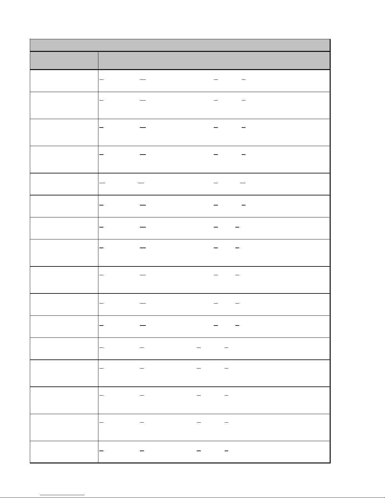
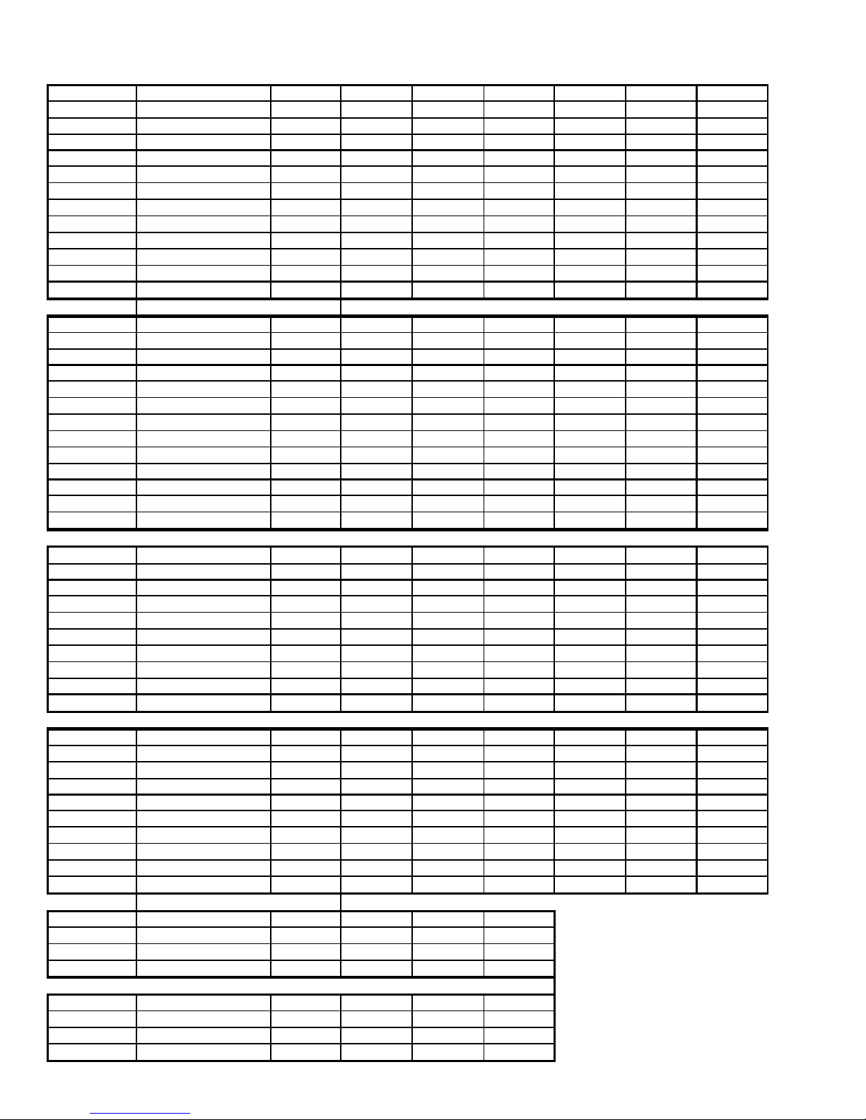
ACCESSORIES
COIL MODEL TX2N2 TXV KIT TX3N2 TXV KIT TX5N2 TXV KIT FSK01A FREEZE PROTECTION KIT
CA*F030B4* --- X --- X
CA*F036B4* --- X --- X
CA*F042C4* --- --- X X
CA*F048C4* --- --- X X
CA*F057D4* --- --- X X
CA*F060D4* --- --- X X
CHPF030A4* --- X --- X
CHPF036B4* --- X --- X
CHPF042A4* --- --- X X
CHPF048D4* --- --- X X
CHPF060D4* --- --- X X
CH36FCB --- X --- X
CH48FCB --- --- X X
CH60FCB --- --- X X
CA*F18246* X X --- X
CA*F30306* --- X --- X
CA*F36426* --- X X X
CHPF18246* X --- X X
CHPF30306* --- --- X X
CHPF36426* --- --- X X
CSCF1824N6* X --- --- X
CSCF303N6* --- X --- X
CSCF3642N6* --- X X X
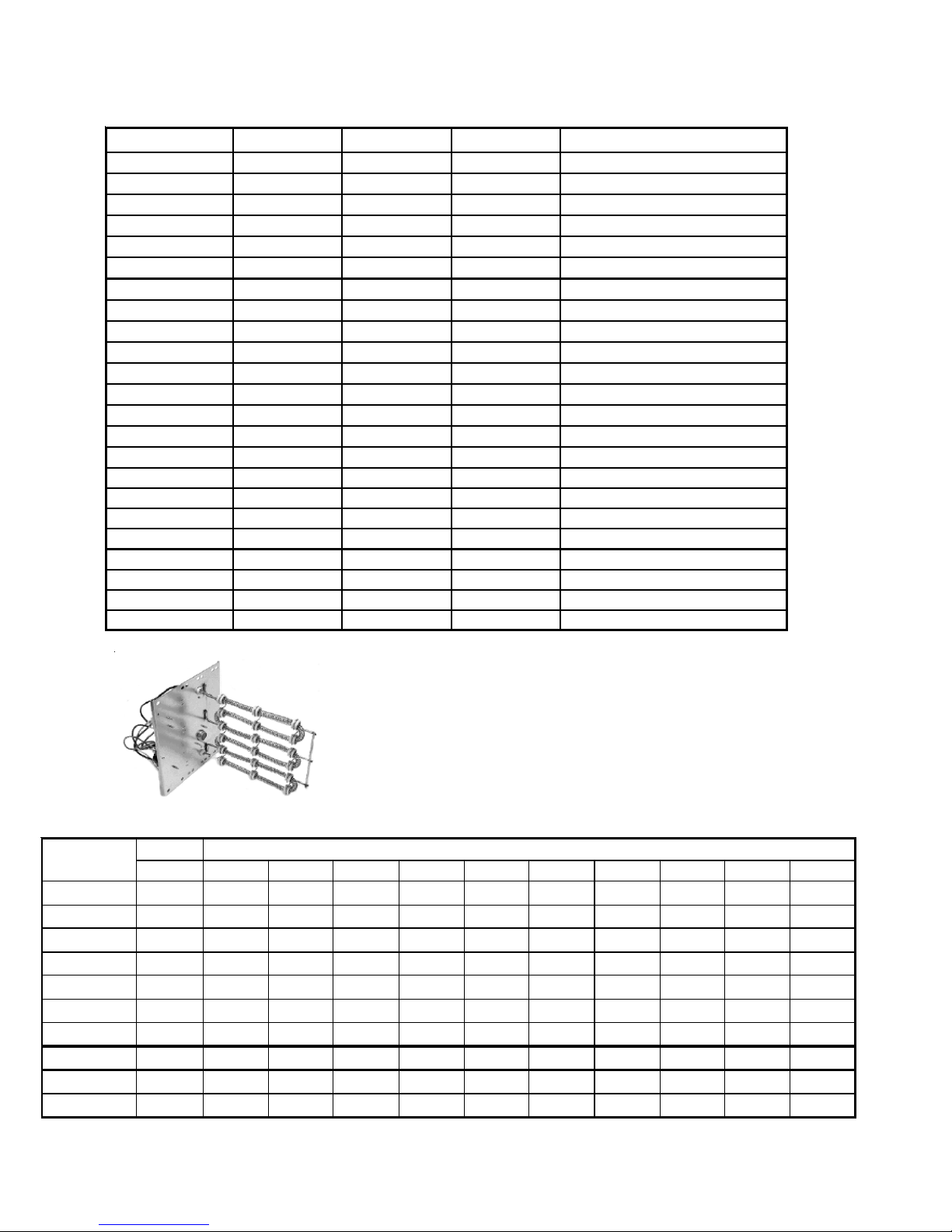
COIL ACCESSORIES
HKR SERIES ELECTRIC HEA T KITS
ELECTRIC HEAT KIT APPLICATIONS
MBR & MBE
BLOWER
MBR0800AA-1AA - X X X X X
MBR1200AA-1AA- XXXXXXXXXX
MBR1600AA-1AA- XXXXXXXXXX
MBR2000AA-1AA- XXXXXXXXXX
MBE1200AA-1AA - - - - X X X - - - MBE1600AA-1AA - - - - - X X - - - MBE2000AA-1AA - - - - - X X X - - MBE1200AA-1BA - X X X X X X - - - MBE1600AA-1BA - X X X X X X - - - MBE2000AA-1BA - X X X X X X X - - -
X = Allowable combinations ^ = Circuit 1: Single Phase for Air Handler Motor * = Revision level that my or may not be designated
- = Restricted combinations Circuit 2: 3-Phase for HKR3 Heater Kits C = Circuit Breaker option
NO HEAT HKR-03* HKR05-(C)' HKR-06* HKR-08(C)* HKR-10(C)* HKR-15(C)* HKR-20(C)* HKR-21(C)* ^HKR3-15* ^HKR3-20A
ELE CTRIC HEAT KIT
20

PRODUCT DESIGN
This section gives a basic description of cooling unit operation, its various components and their basic operation.
Ensure your system is properly sized for heat gain and loss
according to methods of the Air Conditioning Contractors
Association (ACCA) or equivalent.
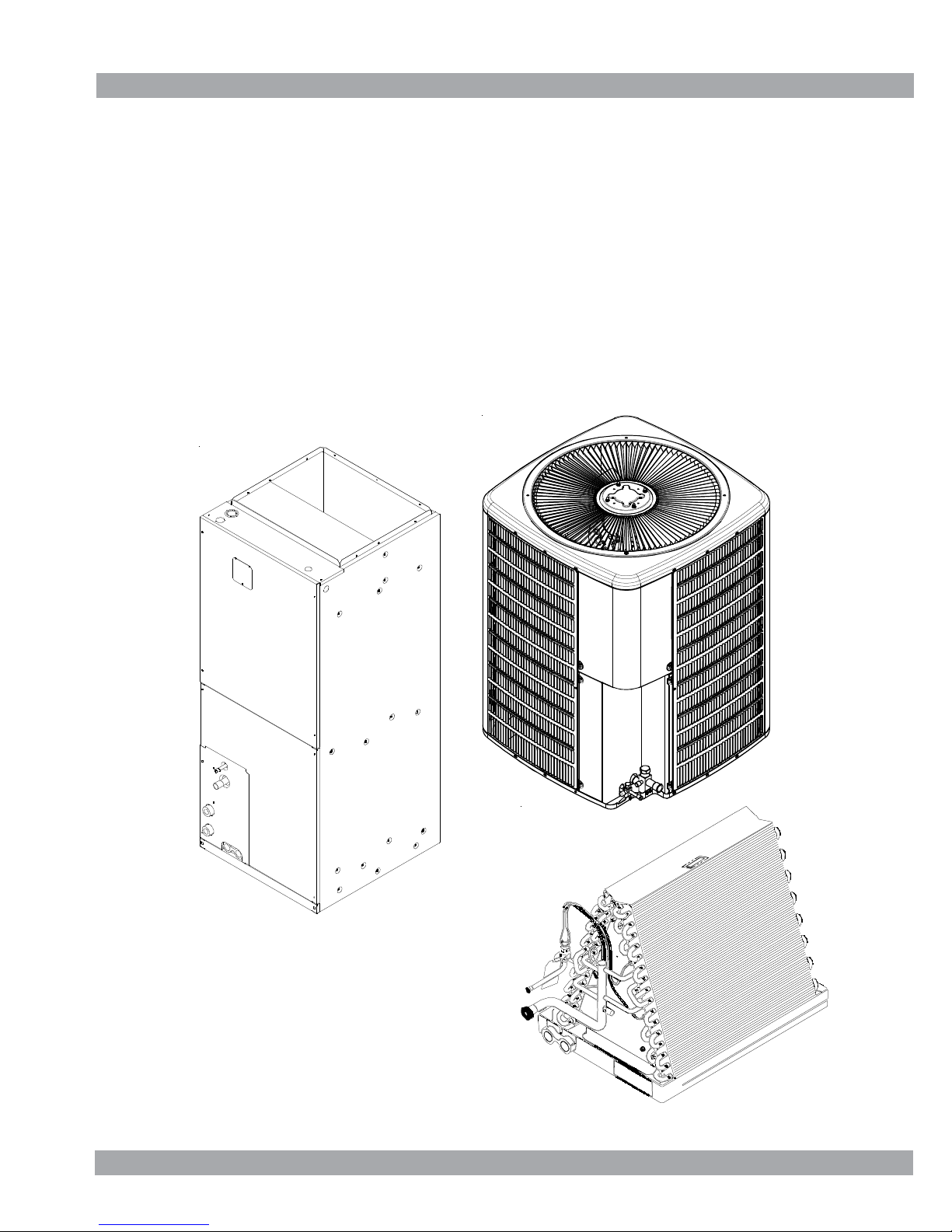
CONDENSING UNIT
These units are designed for free air discharge. Condensed
air is pulled through the condenser coil by a direct drive
propeller fan and then discharged from the cabinet top. The
unit requires no additional resistance (i.e. duct work) and
should not be added.
The GSH13, GSH14, ASH13 and VSH13 Heat Pump condensing units are designed for 208-230 dual voltage single
phase applications. The GSH13 3 ton model is available in
230V, 3 phase applications. The GSH13 4 and 5 ton models
are available for 230V, 3-phase and 460V, 3-phase applications.
The units range in size from 1.5 to 5-ton and have a rating of
13 and 14 SEER. SEER efficiency is dependent upon the unit
and its components. Refer to the "Technical Information"
manual of the unit you are servicing for further details.
The GSC13, GSC14 and ASC13 and VSC13 Condensing
Units are made in 1.5 through 5 ton sizes. They are designed
for 208-240 volt single phase applications. The GSC13 3 ton
model is available in 230V, 3 phase applications. The GSC13
4 and 5 ton models are available for 230V, 3-phase and 460V,
3-phase applications.
Suction and Liquid Line Connections
All units come equipped with suction and liquid valves
designed for connection to refrigerant-type copper. Front
seating valves are factory-installed to accept the field-run
copper. The total refrigerant charge needed for a normal
operation is also factory-installed. For additional refrigerant
line set information, refer to the "Technical Information"
manual of the unit you are servicing.
Compressors
GSC13, VSC13, GSH13 and VSH13 use a mix of reciprocating and scroll compressors, except for the VSC130181AA
which uses a rotary compressor. The ASC13 and ASH13 use
the Copeland Scroll® Compressor. There are a number of
design characteristics which differentiate the scroll compressor from the reciprocating compressor. One is the scroll. A
scroll is an involute spiral which, when matched with a mating
scroll form, generates a series of crescent-shaped gas
pockets between the members (see following illustration).
During compression, one scroll remains stationary while the
other form orbits. This motion causes the resulting gas
pocket to compress and push toward the center of the scrolls.
When the center is reached, the gas is discharged out a port
located at the compressor center.
GSC130361D* and GSC130481AG use Bristol® BENCHMARK™ compressors, the most advanced compressors in
the industry today. The BENCHMARK™ reciprocating compressor can be recognized by a “J” in the fourth character of
the compressor model number. Innovative mechanical design and gas management make the BENCHMARK™ compressor very efficient and remarkably quiet. The sound
content (frequency) delivers exceptional acoustical characteristics and the virtually round housing design is compact
and also helps to reduce the overall sound and vibration.
GSC130181BA use Panasonic® rotary compressors.
COILS AND BLOWER COILS
MBR/MBE blower cabinets are designed to be used as a twopiece blower and coil combination. MBR/MBE blower sections can be attached to cased evaporator coil. This twopiece arrangement allows for a variety of mix-matching
possibilities providing greater flexibility. The MBE blower
cabinet uses a variable speed motor that maintains a constant airflow with a higher duct static.
It is approved for applications with cooling coils of up to 0.8
inches W.C. external static pressure and includes a feature
that allows airflow to be changed by +15%. The MBR blower
cabinet uses a PSC motor. It is approved for applications with
cooling coils of up to 0.5 inches W.C. external static
pressure.
The MBR/MBE blower cabinets with proper coil matches can
be positioned for upflow, counterflow, horizontal right or
horizontal left operation. All units are constructed with R-4.2
insulation. In areas of extreme humidity (greater than 80%
consistently), insulate the exterior of the blower with insulation having a vapor barrier equivalent to ductwork insulation,
providing local codes permit.
The CAPX/CHPX coils are equipped with a thermostatic
expansion valve that has a built-in internal check valve for
refrigerant metering. The CACF/CAPF/CHPF coils are
equipped with a fixed restrictor orifice.
21

PRODUCT DESIGN
The coils are designed for upflow, counterflow or horizontal
application, using two-speed direct drive motors on the
CACF/CAPF/CHPX models and BPM (Brushless Permanent
Magnet) or ECM motors on the MBE models.
The ARUF is a multi-position air handler (upflow/horizontal or
downflow) and is equipped with a flowrator for cooling and heat
pump applications. Because of its seamless copper tubing
and aluminum fins, there are fewer leaks. The steel cabinet
of the ARUF is fully insulated and rust resistant. Thermal
expansion kits for air conditioning and heat pump applications are available.
ARPF*B 2 to 5 ton air handlers are dedicated for downflow
operation and are approved for modular homes. Flowrater.
transformer and blower time delay are on all standard ARPF
units. Both the ARUF and ARPF have direct-drive multispeed motors.
AEPF is a multi-position, variable-speed air handler and can
be used with R-410A or R-22 (models ending in 1/16). The
unit's blower design includes a variable-speed DC motor and
is compatible with heat pumps and variable-capacity cooling
applications.
ASPF is a multi-position air handler that can be used with R410A or R-22 and it features a X-13 motor. This motor is a
constant torque motor with very low power consumption and
it is energized by a 24V signal. The X-13 features an
integrated control module and is compatible with heat pumps
and cooling applications.
22

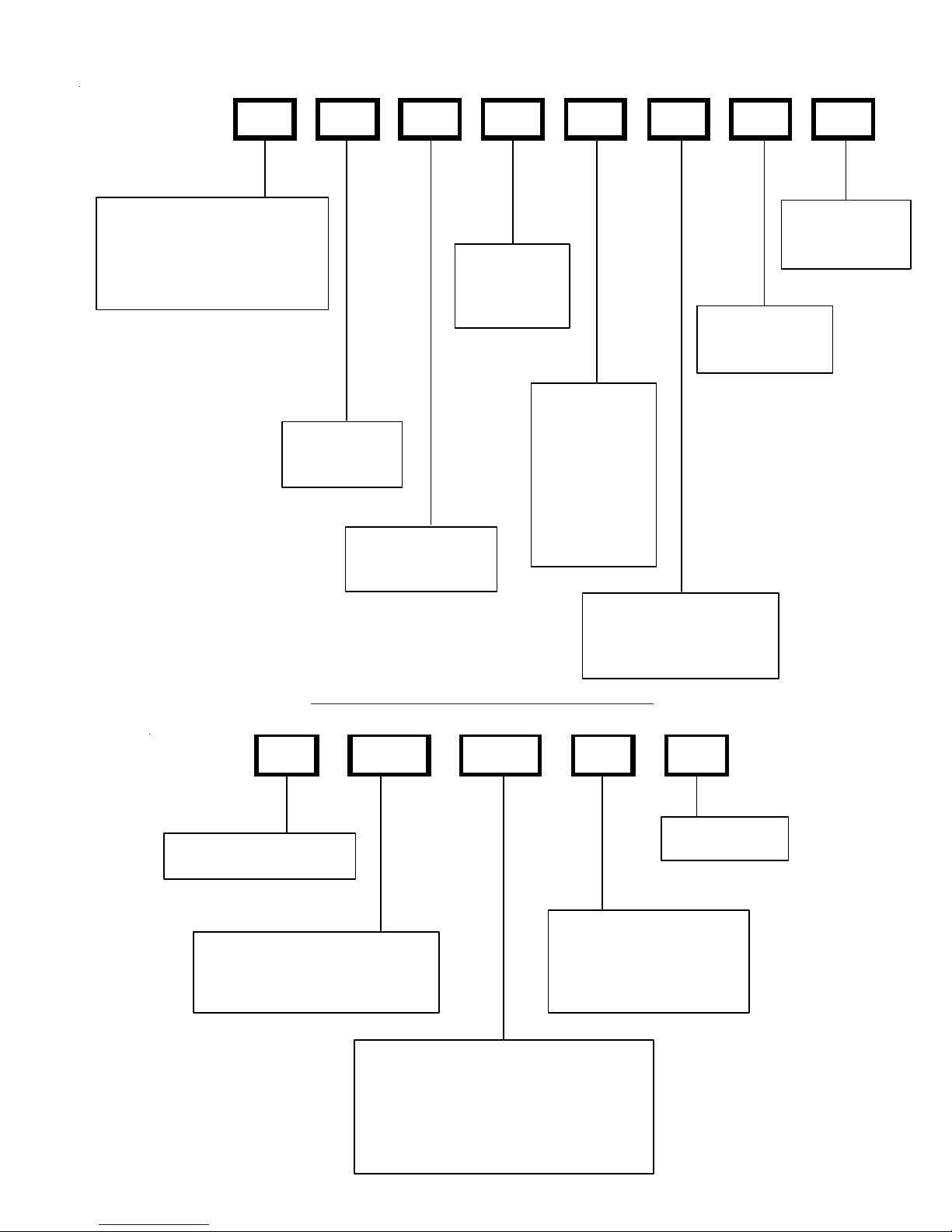
SYSTEM OPERA TION
COOLING
The refrigerant used in the system is R-22. It is a clear,
colorless, non-toxic, non-irritating, and non-explosive liquid.
The chemical formula is CHCLF
atmospheric pressure is -41.4°F.
A few of the important principles that make the refrigeration
cycle possible are: heat always flows from a warmer to a
cooler body, under lower pressure a refrigerant will absorb
heat and vaporize at a low temperature, the vapors may be
drawn off and condensed at a higher pressure and temperature to be used again.
The indoor evaporator coil functions to cool and dehumidify
the air conditioned spaces through the evaporative process
taking place within the coil tubes.
NOTE: The pressures and temperatures shown in the
refrigerant cycle illustrations on the following pages are for
demonstration purposes only. Actual temperatures and pressures are to be obtained from the "Expanded Performance
Chart."
Liquid refrigerant at condensing pressure and temperatures,
(270 psig and 122°F), leaves the outdoor condensing coil
through the drier and is metered into the indoor coil through
the metering device. As the cool, low pressure, saturated
refrigerant enters the tubes of the indoor coil, a portion of the
liquid immediately vaporizes. It continues to soak up heat and
vaporizes as it proceeds through the coil, cooling the indoor
coil down to about 48°F.
Heat is continually being transferred to the cool fins and tubes
of the indoor evaporator coil by the warm system air. This
warming process causes the refrigerant to boil. The heat
removed from the air is carried off by the vapor.
As the vapor passes through the last tubes of the coil, it
becomes superheated, that is, it absorbs more heat than is
necessary to vaporize it. This is assurance that only dry gas
will reach the compressor. Liquid reaching the compressor
can weaken or break compressor valves.
The compressor increases the pressure of the gas, thus
adding more heat, and discharges hot, high pressure superheated gas into the outdoor condenser coil.
In the condenser coil, the hot refrigerant gas, being warmer
than the outdoor air, first loses its superheat by heat transferred from the gas through the tubes and fins of the coil. The
refrigerant now becomes saturated, part liquid, part vapor and
then continues to give up heat until it condenses to a liquid
alone. Once the vapor is fully liquefied, it continues to give up
heat which subcools the liquid, and it is ready to repeat the
cycle.
. The boiling point, at
2
The check valve at the indoor coil will open by the flow of
refrigerant letting the now condensed liquid refrigerant bypass the indoor expansion device. The check valve at the
outdoor coil will be forced closed by the refrigerant flow,
thereby utilizing the outdoor expansion device.
The restrictor orifice used with the CA*F, CHPF coils and the
AR*F air handler will be forced onto a seat when running in
the cooling cycle, only allowing liquid refrigerant to pass
through the orifice opening. In the heating cycle it will be
forced off the seat allowing liquid to flow around the restrictor.
A check valve is not required in this circuit.
COOLING CYCLE
When the contacts of the room thermostat close making
terminals R to Y & G, the low voltage circuit of the transformer
is completed. Current now flows through the magnetic holding coils of the compressor contactor (CC) and fan relay
(RFC).
This draws in the normally open contact CC, starting the
compressor and condenser fan motors. At the same time
contacts RFC close starting the indoor fan motor.
When the thermostat is satisfied, it opens its contacts,
breaking the low voltage circuit, causing the compressor
contactor and indoor fan relay to open, shutting down the
system.
If the room thermostat fan selector switch should be set on
the "on" position, then the indoor blower would run continuous
rather than cycling with the compressor.
Heat pumps energize the reversing valve thorough the "O"
circuit in the room thermostat. Therefore the reversing valve
remains energized as long as the thermostat subbase is in
the cooling position. The only exception to this is during
defrost.
DEFROST CYCLE
The defrosting of the outdoor coil is jointly controlled by the
defrost timing board, defrost (30/60) control, and compressor
run time.
HEATING CYCLE
The reversing valve on the heat pump models is energized in
the cooling cycle through the "O" terminal on the room
thermostat.
These models have a 24 volt reversing valve coil. When the
thermostat selector switch is set in the cooling position, the
"O" terminal on the thermostat is energized all the time.
Care must be taken when selecting a room thermostat. Refer
to the installation instructions shipped with the product for
approved thermostats.
HEATING
The heating portion of the refrigeration cycle is similar to the
cooling cycle. By energizing the reversing valve solenoid coil,
the flow of the refrigerant is reversed. The indoor coil now
becomes the condenser coil, and the outdoor coil becomes
the evaporator coil.
23
SYSTEM OPERA TION
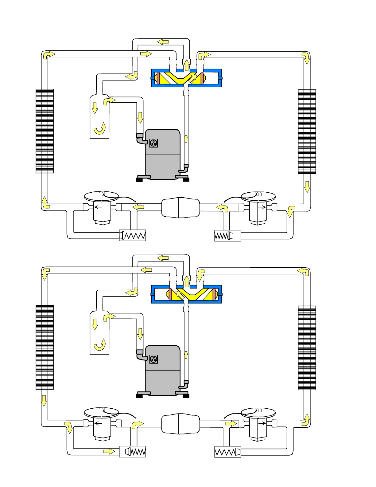
COOLING CYCLE
Reversing Valve
(Energized)
Indoor
Coil
HEATING CYCLE
Outdoor
Coil
Accumulator
Thermostatic
Expansion
Valve
Bi-Flow
Filter Dryer
Check Valve
Indoor
Coil
Accumulator
24
Reversing Valve
(De-Energized)
Outdoor
Coil
Thermostatic
Expansion
Valve
Bi-Flow
Filter Dryer
Check Valve
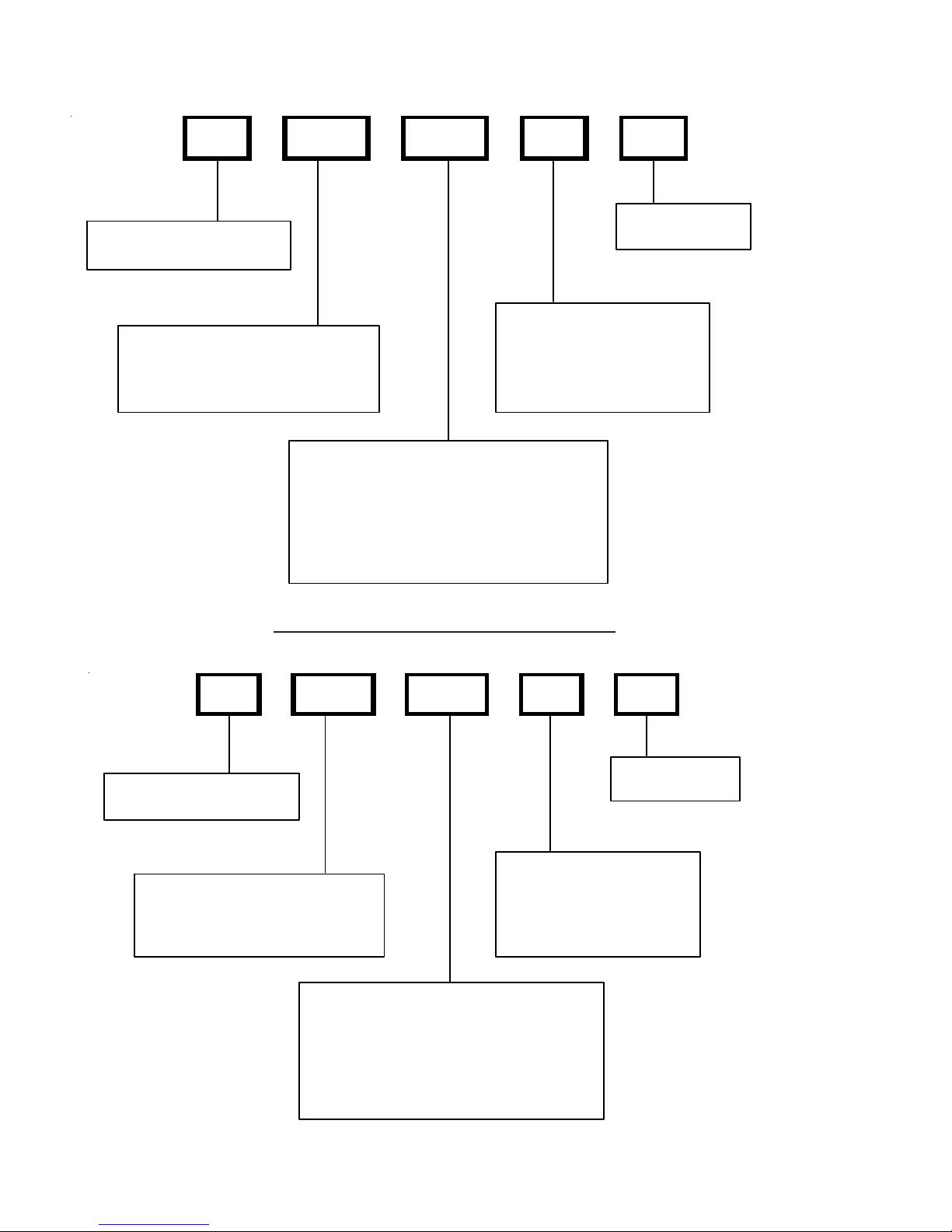
SYSTEM OPERA TION
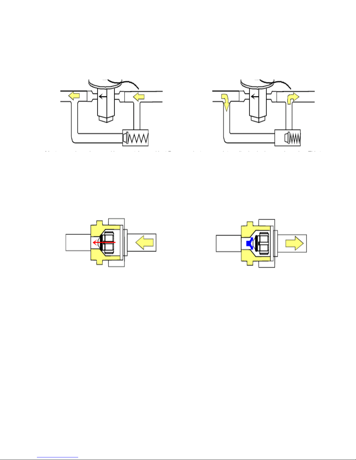
EXPANSION VALVE/CHECK VALVE ASSEMBLY
IN COOLING OPERATION
Most expansion valves used in current Amana
use an internally checked expansion valve.
This type of expansion valve does not require an external check valve as shown above.
However, the principle of operation is the same.
RESTRICTOR ORIFICE ASSEMBLY
IN COOLING OPERATION
EXPANSION VALVE/CHECK VALVE ASSEMBLY
IN HEATING OPERATION
®
Brand Heat Pump products
RESTRICTOR ORIFICE ASSEMBLY
IN HEATING OPERATION
In the cooling mode, the orifice is pushed into its
seat, forcing refrigerant to flow through the metered
hole in the center of the orifice.
In the heating mode, the orifice moves back off its
seat, allowing refrigerant to flow unmetered around
the outside of the orifice.
25
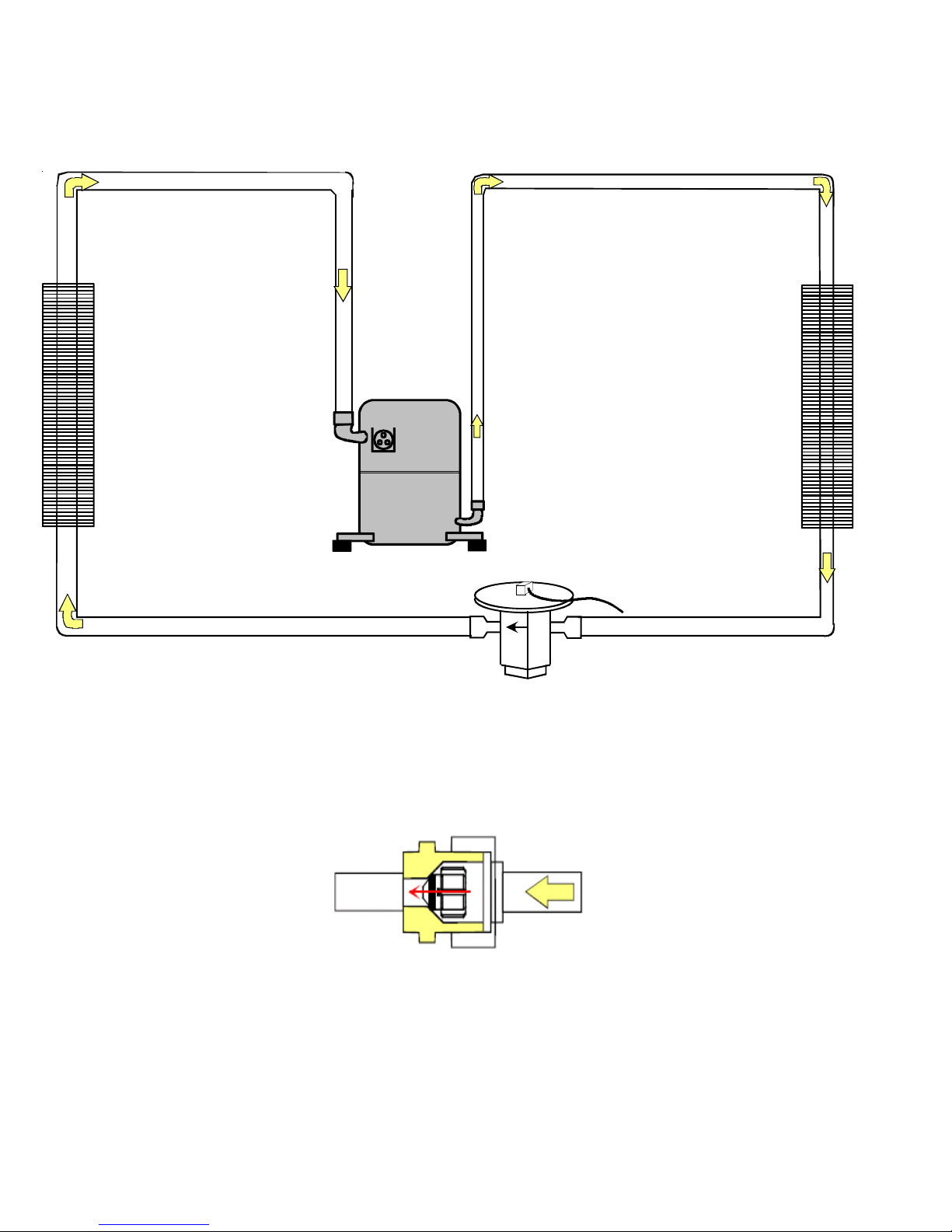
SYSTEM OPERA TION
COOLING CYCLE - CONDENSING UNIT
Indoor
Coil
Outdoor
Coil
Thermostatic
Expansion
Valve
In the cooling mode, the orifice is pushed into its
seat, forcing refrigerant to flow through the metered
26
hole in the center of the orifice.
SYSTEM OPERA TION
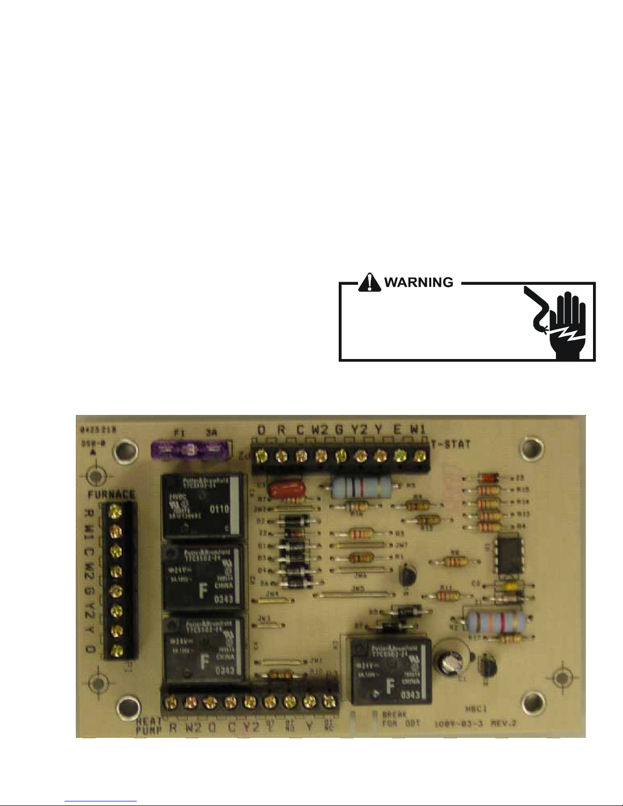
AFE18-60A CONTROL BOARD
DESCRIPTION
The AFE18 control is designed for use in heat pump applications where the indoor coil is located above/downstream of a
gas or fossil fuel furnace. It will operate with single and two
stage heat pumps and single and two stage furnaces. The
AFE18 control will turn the heat pump unit off when the
furnace is turned on. An anti-short cycle feature is also
incorporated which initiates a 3 minute timed off delay when
the compressor goes off. On initial power up or loss and
restoration of power, this 3 minute timed off delay will be
initiated. The compressor won’t be allowed to restart until the
3 minute off delay has expired. Also included is a 5 second
de-bounce feature on the “Y, E, W1 and O” thermostat inputs.
These thermostat inputs must be present for 5 seconds
before the AFE18 control will respond to it.
An optional outdoor thermostat, OT18-60A, can be used with
the AFE18 to switch from heat pump operation to furnace
operation below a specific ambient temperature setting, i.e.
break even temperature during heating. When used in this
manner, the “Y” heat demand is switched to the “W1” input
to the furnace by the outdoor thermostat and the furnace is
used to satisfy the first stage “Y” heat demand. On some
controls, if the outdoor thermostat fails closed in this position
during the heating season, it will turn on the furnace during
the cooling season on a “Y” cooling demand. In this
situation, the furnace produces heat and increases the
indoor temperature thereby never satisfying the cooling
demand. The furnace will continue to operate and can only
be stopped by switching the thermostat to the off position or
removing power to the unit and then replacing the outdoor
thermostat. When the AFE18 receives a “Y” and “O”
input from the indoor thermostat, it recognizes this as a
cooling demand in the cooling mode. If the outdoor thermostat is stuck in the closed position switching the “Y” demand
to the “W1” furnace input during the cooling mode as
described above, the AFE18 won’t allow the furnace to
operate. The outdoor thermostat will have to be replaced to
restore the unit to normal operation.
HIGH VOLTAGE!
Disconnect ALL power before servicing
or installing. Multiple power sources
may be present. Failure to do so may
cause property damage, personal injury
or death.
27
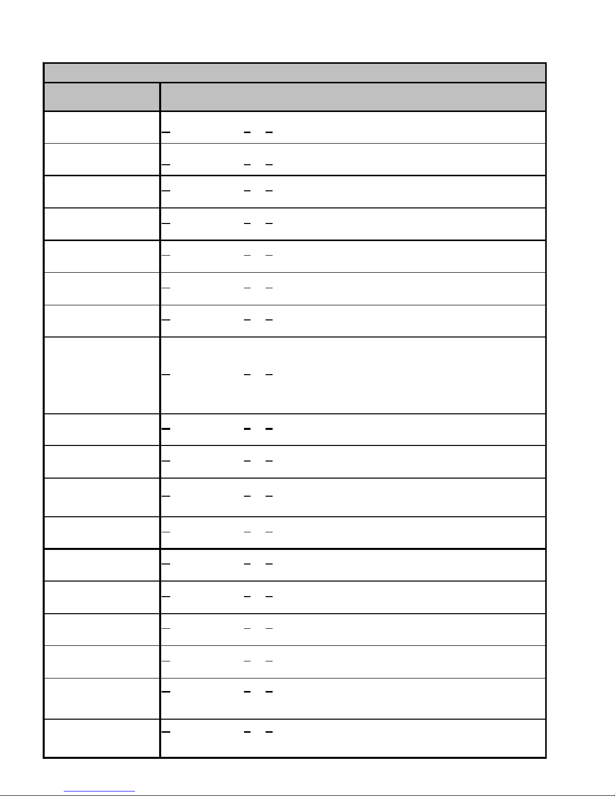
TROUBLESHOOTING CHART
COOLING/HP ANALYSIS CHART
Complaint
POSSIBLE CAUSE
DOTS IN ANALYSIS
GUIDE INDICATE
"POSSIBLE CAUSE"
Power Failure
Blown Fuse
Unbalanced Power, 3PH
Loose Connection
Shorted or Broken Wires
Open Fan Overload
Faulty Thermostat
Faulty Transformer
Shorted or Open Capacitor
Internal Compressor Overload Open
Shorted or Grounded Compressor
Compressor Stuck
Faulty Compressor Contactor
Faulty Fan Relay
Open Control Circuit
Low Voltage
Faulty Evap. Fan Motor
Shorted or Grounded Fan Motor
Improper Cooling Anticipator
Shortage of Refrigerant
Restricted Liquid Line
Open Element or Limit on Elec. Heater
Dirty Air Filter
Dirty Indoor Coil
Not enough air across Indoor Coil
Too much air across Indoor Coil
Overcharge of Refrigerant
Dirty Outdoor Coil
Noncondensibles
Recirculation of Condensing Air
Infiltration of Outdoor Air
Improperly Located Thermostat
Air Flow Unbalanced
System Undersized
Broken Internal Parts
Broken Valves
Inefficient Compressor
Wrong Type Expansion Valve
Expansion Device Restricted
Oversized Expansion Valve
Undersized Expansion Valve
Expansion Valve Bulb Loose
Inoperative Expansion Valve
Loose Hold-down Bolts
Faulty Reversing Valve
Faulty Defrost Control
Faulty Defrost Thermostat
Flowrator Not Seating Properly
No Cooling Unsatisfactory Cooling/Heating
SYMPTOM
System will not start
Compressor will not start - fan runs
Comp. and Cond. Fan will not start
Evaporator fan will not start
Condenser fan will not start
Compressor runs - goes off on overload
Compressor cycles on overload
System runs continuously - little cooling/htg
Too cool and then too warm
Not cool enough on warm days
•
•••
•••
•••
••••••
••
••• •
••
• ••••
•
••
•••
•••
•
•
•••
••
••
••
••
•• •• •
♦♦
••• •
••• •
••• •
•• •
•• •
••
•• •
•••
••
••
••
•• ••
•
••• • ••
••• • •• •
••
••• • •
•• •
•
•
•
Cooling or Heating Cycle (Heat Pump) ♦
•••
System
Operating
Pressures
Certain areas too cool, others too warm
Compressor is noisy
System runs - blows cold air in heating
Unit will not terminate defrost
Unit will not defrost
Low suction pressure
Low head pressure
High suction pressure
High head pressure
Test Voltage S-1
Inspect Fuse Size & Type S-1
Test Voltage S-1
Inspect Connection - Tighten S-2, S-3
Test Circuits With Ohmmeter S-2, S-3
Test Continuity of Overload S-17A
Test Continuity of Thermostat & Wiring S-3
Check Control Circuit with Voltmeter S-4
Test Capacitor S-15
♦
♦
♦
♦
♦
♦
•
♦
••
♦
♦
••
••
•
♦♦♦ ♦♦♦
♦♦♦♦♦ ♦
♦♦♦♦♦♦♦
Heating Cycle Only (Heat Pump)
Test Continuity of Overload S-17A
Test Motor Windings S-17B
Use Test Cord S-17D
Test Continuity of Coil & Contacts S-7, S-8
Test Continuity of Coil And Contacts S-7
Test Control Circuit with Voltmeter S-4
Test Voltage S-1
Repair or Replace S-16
♦
Test Motor Windings S-16
Check Resistance of Anticipator S-3B
Test For Leaks, Add Refrigerant S-101,103
Remove Restriction, Replace Restricted Part S-112
Test Heater Element and Controls S-26,S-27
Inspect Filter-Clean or Replace
♦
Inspect Coil - Clean
♦
Check Blower Speed, Duct Static Press, Filter S-200
♦
Reduce Blower Speed S-200
•
Recover Part of Charge S-113
••
Inspect Coil - Clean
•
Recover Charge, Evacuate, Recharge S-114
•
Remove Obstruction to Air Flow
Check Windows, Doors, Vent Fans, Etc.
Relocate Thermostat
Readjust Air Volume Dampers
Refigure Cooling Load
Replace Compressor S-115
Test Compressor Efficiency S-104
Test Compressor Efficiency S-104
Replace Valve S-110
♦
Remove Restriction or Replace Expansion Device S-110
Replace Valve
Replace Valve
Tighten Bulb Bracket S-105
Check Valve Operation S-110
Tighten Bolts
Replace Valve or Solenoid S-21, 122
Test Control S-24
Test Defrost Thermostat S-25
Check Flowrator & Seat or Replace Flowrator S-111
Test Method
Remedy
See Service Procedure Ref.
28
 Loading...