

Goodman GSASD-10, GSASD-11, GSASD-12, GSASD-18, ASASD-10 Installation, Operation And Service Instructions
...
INSTALLATION, OPERATION AND
SERVICE INSTRUCTIONS
MODELS
GSASD-10, GSASD-11, GSASD-12, GSASD-18
ASASD-10, ASASD-1 1, ASASD-12, ASASD-18
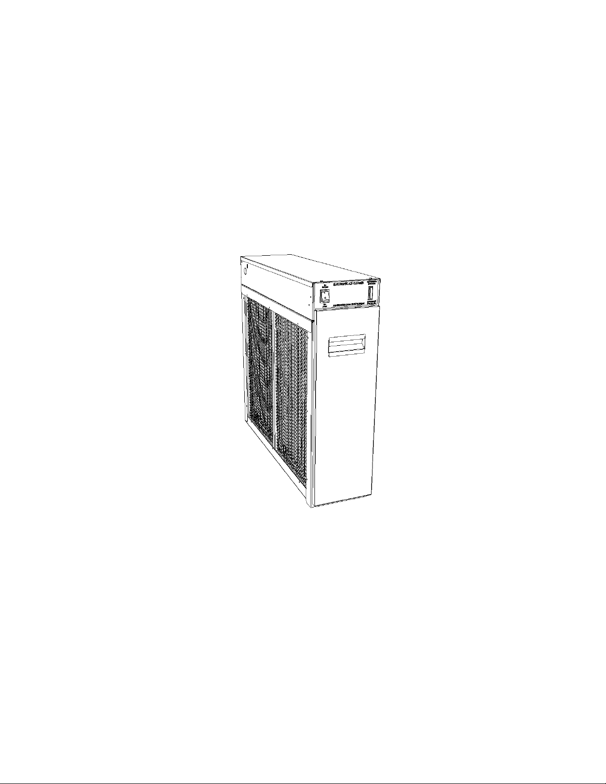
ELECTRONIC AIR CLEANERS
IMPORTANT: PLEASE READ MANUAL BEFORE OPERATING UNIT
Features
•
Lifetime Filter System never needs replacing
• Electronically removes dust, mites, pollen, pet dander, tobacco smoke, cooking smoke
and grease, mold, fungi, bacteria, viruses and more, down to 0.01 micron
• Dual Voltage, Aluminum Collecting Cells are durable and easy to maintain
• Cell Guide ensures proper placement of collecting cells
• Activated Carbon Filters remove unpleasant odors
• Electronic Air Proving Switch for quick wiring
• Dual Indicator Lights show Air Cleaner is working at a glance
• Galvanized Steel Cabinet for solid vertical or horizontal installation
• Durable Scratch-Resistant powder coat paint finish resists corrosion
FOR QUESTIONS REGARDING INSTALLATION, OPERATION & SERVICE,
CALL THE AIR CLEANER HOTLINE TOLL-FREE
1-800-267-8305
IMPORTANT: Please read entire instructions before
installing the Electronic Air Cleaner.
CONTENTS
SAFETY CONSIDERATIONS 2
WHAT THE ELECTRONIC AIR CLEANER DOES 2
BENEFITS 2
HOW IT WORKS 2
SPECIFICATIONS 3
COMPONENTS 3
INSTALLATION 3-5
Static Pressure 3
Location 3
Installation Location With Humidifier 4
Installation Location With Air Conditioner 4
Electronic Air Cleaner Installation 5
Wiring 5
SYSTEM CHECK 5
OPERATION 6
WHITE DUST 6
MAINTENANCE 6
Cell and Prefilter Cleaning 6
Activated Carbon Filter Replacement 6
SERVICE 7-10
Quick Check 7
Testing For High Voltage At Power Board 7
Measuring High Voltage At Power Board 7
Replacing Performance Light 7
Replacing A Power Board 8
Testing Air Proving Switch (APS) 8
Replacing An Air Proving Switch (APS) 8
Testing The 24 V Transformer 8
Replacing The 24 V Transformer 8
Setting Voltage Of Power Board 9
Setting Voltage Without High Voltage Meter 9
Testing For Voltage At The Cell 9
Testing Cell For Bad Contacts 9
Testing Cell With An Ohmmeter
Removing Power Box
Replacing A Tungsten Ionizing Wire 10
EXPLODED VIEW 10
PARTS LIST 11
TROUBLESHOOTING GUIDE 12
WARRANTY 15
10
Before beginning any installation or modification, be
certain that the main line electrical disconnect switch is
in OFF position. Electric shock could result. Tag
disconnect switch with suitable warning labels.
Installation and servicing of Electronic Air
Cleaners can be hazardous. Only trained and
qualified service personnel should install, repair, or
service Electronic Air Cleaners.
Homeowners or untrained personnel can perform
the basic maintenance functions of cleaning and
replacing filters.
When working on air cleaning equipment,
observe precautions in the manual, labels attached to
the unit, and other safety precautions that may apply.
Follow all safety codes. Wear safety glasses and
work gloves.
WHAT THE ELECTRONIC AIR CLEANER DOES
Your High Efficiency Electronic Air Cleaner has been
designed to remove atmospheric and household dust,
coal dust, insecticide dust, mites, pollen, mold spores,
fungi, bacteria, viruses, pet dander, cooking smoke and
grease, tobacco smoke particles, and more down to .01
micron (.01 micron = 1/2,540,000 of an inch).
• Helps provide relief for allergy or asthma suffering.
• Helps prevent damaging black dust from staining
walls and furnishings, reducing the amount of time
and money spent cleaning and redecorating.
• Helps eliminate unpleasant odors (with use of Carbon
Filters).
• Helps protect heating/cooling equipment, prolonging
the operating efficiency.
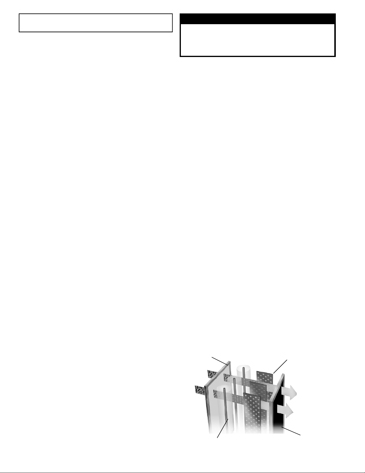
The High Efficiency Electronic Air Cleaner operates
on the principle of electrostatic precipitation. Millions of
airborne pollutants are carried through the return air ducts
of the heating/cooling system and treated through four
stages of filtration.
9
The prefilters (2) remove all large visible particles
such as lint. Smaller particles then pass through a two-
stage electrostatic collecting cell (2). First, particles are
given a powerful positive electrical charge by the ionizing
wires. Second, charged part icles move into the collecting
2 Prefilter
WARNING
BENEFITS
HOW IT WORKS
4 Collecting Cell Plates
Certified for shock and electrical fire hazard only.
1 Dirty Air
SAFETY CONSIDERATIONS
Read and follow instructions carefully. Follow all local
electrical codes during installation. All wiring must
conform to local and national electrical codes. Improper
wiring or installation may damage Air Cleaner.
Understand the signal words WARNING and
CAUTION which are present in the Owner’s Manual.
WARNING and CAUTION signifies a hazard which
could result in property damage, personal injury or death.
3 Ionizing Section
Fig. 1
6 Clean Air to Heating/
Cooling System
5 Carbon Filters (3)
(optional)
2
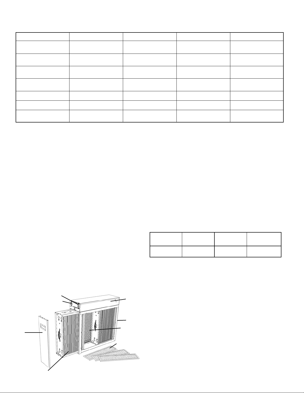
Table 1 — SPECIFICATIONS
MODEL GSASD-10 GSASD-11 GSASD-12 GSASD-18
House Size Area <2400 ft²
<222.96 m²
Airflow up to 1200 CFM
up to 2040 m³/hr
Duct Size 16 x 20 in
40.5 x 51.0 cm
Unit Weight 35 lbs
15.9 kg
Input Voltage 120 V 60 Hz 120 V 60 Hz 120 V 60 Hz 120 V 60 Hz
Power Consumption 30 Watts 30 Watts 30 Watts 30 Watts
Upgrades Included Carbon Filters
Air Switch
area where they are attracted to a series of grounded
plates. Pollutants are held in this section like a magnet
until washed away during cleaning. Lastly, clean air
passes over activated carbon filters (3) for odor removal.
The Electronic Air Cleaner, available in four models
with air flow capacities of up to 1200, 1400 and 2000
CFM (2040, 2380 and 3400 m³/hr), is adaptable to all
residential forced air heating or cooling systems.
COMPONENTS
Cabinet: Constructed of heavy gauge galvanized steel
to resist corrosion and provide trouble-free installation.
Holes are provided to facilitate mounting to the ductwork
or air handling equipment.
Power Box: Removable. Contains the power switch,
performance indicator light, safety interlock switch, high
voltage power board, air proving switch and high voltage
<3000 ft²
<278.70 m²
up to 1400 CFM
up to 2380 m³/hr
16 x 25 in
40.5 x 63.5 cm
37 lbs
16.8 kg
Carbon Filters
Air Switch
<3000 ft²
<278.70 m²
up to 1400 CFM
up to 2380 m³/hr
20 x 20 in
51.0 x 51.0 cm
37 lbs
16.8 kg
Carbon Filters
Air Switch
APS will detect airflow (fan on) and energize the Air
Cleaner.
Collecting Cells: Consist of an ionizing section and a
plate section. The arrow on the cell must point toward the
system fan.
Prefilters: Constructed of aluminum mesh, to prevent
lint and large particles from entering the collecting cells.
Carbon Filters: Remove odors. Must be replaced every
six months - not washable. Maximum of (3) carbon filters
can be used at same time.
INSTALLATION
Static Pressure
The static pressure drop across the Air Cleaner will
vary with CFM and whether the optional carbon filters
have been installed in the unit.
contacts.
The power board is uniquely equipped with a variable
resistor (potentiometer) to adjust high voltage output.
Output has been pre-set for optimum efficiency. As
voltage varies in extreme conditions of dryness, humidity
or proximity to hydro towers, raising or lowering
100% Air Flow
No Carbon
0.158 0.250 0.030 0.060
100% Air Flow
With Carbon
40% Air Flow
No Carbon
Table 2 — Pressure Drop (Inches WC)
potentiometer allows for proper voltage output.
Air Proving Switch (APS): Integrated. Automatically
cycles Air Cleaner on and off with the system fan. The
Performance Indicator Light
ON/OFF Switch
Power Box
Location
The Air Cleaner must only be installed in the return
air duct, as close to the fan compartment as possible.
This location provides the most even airflow across the
collecting cells and allows the Air Cleaner to keep the
system motor and blower clean. The installation can be
vertical or horizontal. When choosing a location, there
Cabinet
Prefilters (2)
Door
Activated Carbon
Filters (3)
must be adequate room to wire the Air Cleaner and
remove prefilters, collecting cells and power box for
maintenance.
Note: Once Air Cleaner has been installed, do not allow
the placement of any device such as a new hot water
heater, water softener, gas pipe, or electrical cable to be
put 2 ft. in front of or within 6 in. (15 cm) from top of Air
Cleaner, in order to allow removal of filters and Air
Cleaner parts, which are necessary for maintenance or
Collecting Cells (2)
Fig. 2
servicing.
>3000 ft²
>278.70 m²
up to 2000 CFM
up to 3400 m³/hr
20 x 25 in
51.0 x 63.5 cm
41 lbs
18.6 kg
Carbon Filters
Air Switch
40% Air Flow
With Carbon
3
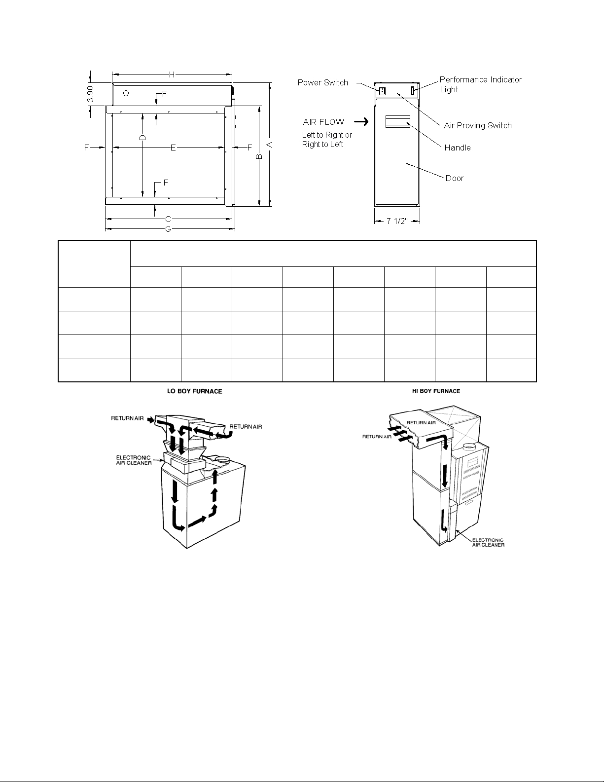
Fig. 3 — DIMENSIONS
MODEL
GSASD-10
GSASD-11
GSASD-12
GSASD-18
DIMENSIONS — in (cm)
A B C D E F G H
19.8
(50.4)
19.8
(50.4)
24.7
(62.8)
24.7
(62.8)
15.9
(40.5)
15.9
(40.5)
20.8
(52.9)
20.8
(52.9)
23.2
(58.9)
26.1
(66.3)
21.2
(53.9)
25.8
(65.4)
13.1
(33.3)
13.6
(34.6)
18.0
(45.7)
18.0
(45.7)
20.7
(52.5)
24.1
(61.2)
18.7
(47.5)
23.3
(59.1)
1.3
(3.2)
1.0
(2.5)
1.3
(3.2)
1.3
(3.2)
23.7
(60.2)
26.6
(67.7)
21.7
(55.2)
26.3
(66.8)
21.2
(53.9)
25.8
(65.4)
21.2
(53.9)
25.8
(65.4)
Fig. 4 — AIR CLEANER INSTALLATION LOCATION
Allow 24 in (600 mm) clearance for cleaning air cleaner. Allow 6 in. (150 mm) clearance for power box removal.
Installation Location With Humidifier
A humidifier should be installed in the furnace warm
air duct. However, it may be installed in the return duct
without causing problems to the Air Cleaner. Care must
be taken to ensure that the humidifier does not leak, as
this may cause arcing and a mineral deposit to build up
on the collecting cells.
An atomizing type humidifier should be installed
downstream from the Air Cleaner. If the atomizing type
humidifier is installed upstream, high humidity, salts and
minerals may decrease the efficiency of the collecting
cells and cause service problems.
If the atomizing type humidifier must be installed
upstream, the following precautions should be taken:
1. Atomizing type humidifier must be installed as far
from the Air Cleaner as possible.
2. Collecting cells must be washed frequently to prevent
a mineral deposit build-up.
Installation Location With Air Conditioner
Whenever possible, the Air Cleaner should be
installed upstream of the cooling coil. This location will
clean the air before it reaches the evaporator coil.
4
Electronic Air Cleaner Installation
1. Remove existing equipment filter. Thoroughly clean
fan compartment and ductwork where Air Cleaner is
to be installed.
2. Open access door. Slide filters and collecting cells
out of cabinet.
3. Place cabinet in ductwork. Holes are provided to
attach cabinet to ductwork or equipment. If the
adjoining ductwork is flanged, install the screws so
that the screw heads are inside the cabinet. This will
help prevent damage to prefilter and carbon filters
during removal for cleaning. Never put screws or
rivets into the removable power box.
When the air duct does not fit the Air Cleaner
opening, a gradual transition is recommended to
reduce air turbulence though the air Air Cleaner and
to increase its efficiency. There should not be more
than 20º of expansion used on each side of the
transition fitting. Do not reduce ductwork to a smaller
Air Cleaner or it will increase the velocity of airflow.
4. If the Air Cleaner is installed adjacent to an elbow or
angle fitting, turning vanes are recommended to
improve air distribution across the collecting cells.
5. After the Air Cleaner has been installed, seal seams
airtight with duct tape or caulking to prevent dust
from entering the system.
6. Replace the prefilters in the track on the air entering
side. Place the carbon filters evenly spaced in the
track on the air exiting side. The collecting cells are
placed between the tracks, with the arrow on cell
pointing towards the fan. The cell handle may need
to be repositioned if the airflow is in a different
direction than the left to right set up. The handle
should face the door. Close access door.
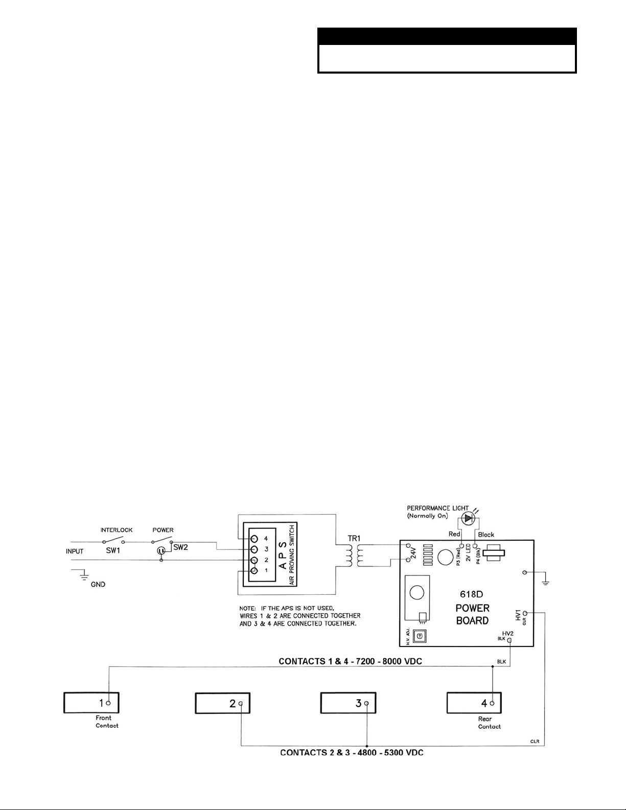
Wiring
WARNING
Electrical shock can cause injury or death. Be certain
main line disconnect switch is off before wiring.
Wiring should only be performed by qualified personnel
only. All wiring must comply with all applicable codes and
standards. The voltage of the power source must match
the voltage indicated on the Air Cleaner. The Air Cleaner
must operate ONLY when the system fan is running.
Make sure the Air Cleaner is properly grounded.
If the air cleaner is equipped with a cord and plug,
the air cleaner can be plugged into an outlet within 6 feet
of the unit. Do not use an extension cord if the outlet is
too far away. Have an electrician wire in a new outlet
closer to the air cleaner.
If the air cleaner is not equipped with a cord, then
wire the Air Cleaner directly to a 120 V power source,
preferably to the same source that is supplying power to
the furnace or air handler. The APS will power the Air
Cleaner when there is sufficient airflow to activate the
sensor. See Fig 5.
Note: The power switch will be lit even if there is no
airflow.
If the unit is to be wired to the EAC contacts on the
system module, check that there is sufficient voltage to
the EAC contacts with the fan operating in all conditions.
Some systems do not power the contacts on low speed.
SYSTEM CHECK
Perform the following system check before operation.
1. Replace prefilters, collecting cells and carbon filters.
Close access door.
2. Turn Air Cleaner power switch ON. Ensure system
fan is operating. Both the power switch light and
performance indicator light should be lit. The power
switch light indicates the Air Cleaner has unit voltage.
The performance indicator light shows that the Air
Cleaner is operating.
Fig. 5 — Air Cleaner Schematic (with Air Proving Switch)
5
 Loading...