

Page 1
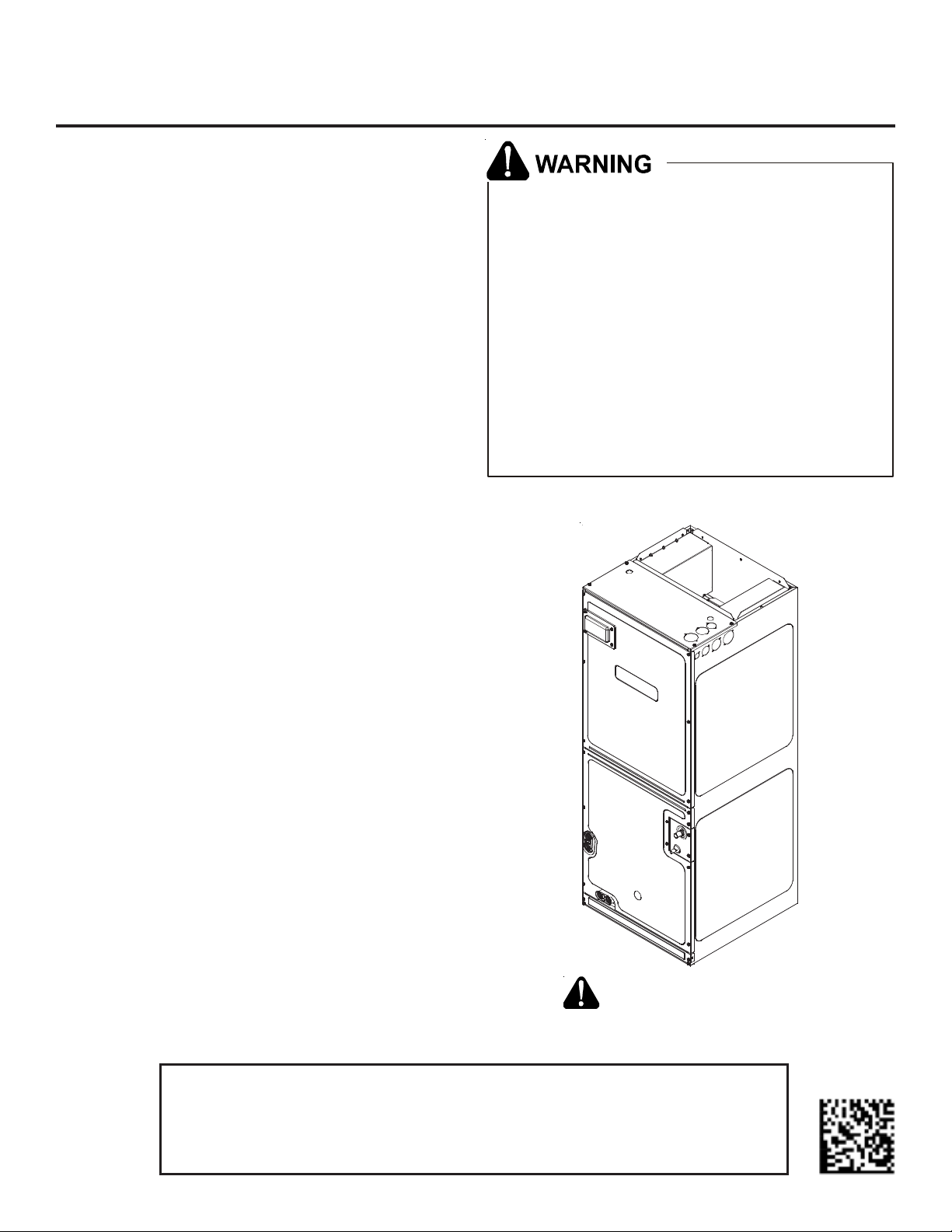
ARUF**14** / ASPT**14**
AIR HANDLERS INSTALLATION & OPERATING INSTRUCTIONS
Contents
1 Important Safety Instructions................................... 1
2 Shipping Inspection ............................................... 3
2.1 Parts.............................................................3
2.2 Handling ........................................................3
3 Codes & Regulations .............................................. 3
4 Replacement Parts ................................................ 3
5 Pre-Installation Considerations ................................ 3
5.1 Preparation.....................................................3
5.2 System Matches................................................3
5.3 Interconnecting Tubing .......................................3
5.4 Clearances......................................................3
5.5 Horizontal Applications ......................................3
6 Installation Location ............................................. 4
6.1 Upflow Installation ...........................................4
6.2 Horizontal Left Installation .................................4
6.3 Horizontal Right Installation / Downflow Installation ..4
7 Refrigerant Lines .................................................. 6
7.1 Tubing Size .....................................................6
7.2 Tubing Preparation ............................................6
7.3 Special Instructions ...........................................6
7.4 Tubing Connections for Flowrator Model ..................8
7.5 Tubing Connections for TXV Models ........................8
7.6 ASPT**14** Models with Non-Adjustable TXV .............8
7.7 Thermal Expansion Valve System Adjustment ............9
8 Condensate Drain Lines ......................................... 10
9 Ductwork........................................................... 11
9.1 Return Ductwork ............................................ 11
10 Return Air Filters ............................................... 11
11 Electric Heat..................................................... 11
12 Electrical and Control Wiring ................................ 12
12.1 Building Electrical Service Inspection .................. 12
12.2 Wire Sizing .................................................. 12
12.3 Maximum Overcurrent Protection (MOP) .............. 12
12.4 Electrical Connections – Supply Voltage................ 12
12.4.1 Air Handler Only (Non-Heat Kit Models) ...... 14
12.4.2 Air Handler - Non-Circuit Breaker Heat Kits . 14
12.4.3 Air Handler With Circuit Breaker Heat Kit ... 14
12.5 Low Voltage Connections ................................. 14
12.5.1 Thermostats ....................................... 14
12.6 Speed Tap Adjustment .................................... 14
13 Achieving 1.4% Low Leakage Rate .........................14
14 Start-Up Procedure............................................. 15
15 Regular Maintenance........................................... 15
16 Airflow Data ..................................................... 16
17 Air Handler Low Voltage Connections ...................... 18
18 Wiring Diagrams................................................. 19
Only personnel that have been trained to install,
adjust, service or repair (hereinafter, “service”) the
equipment specified in this manual shou ld service
the equipment. The man u fa cturer will not be
responsible for any injury or property damage aris ing
from improper service or service procedures. If you
service this un it, you assume responsibility for any
injury or property damage which may result. In
addition, in jurisdictions that require one or more
licenses to service the equipment specified in this
manual, only licensed personnel should service the
equipment. Improper installation, adjustment,
servicing or repair of the equipment specified in this
manual, or attempting t o install, adjust, service or
repair the equipment specified in this manual without
proper t raining may result in product damage,
propert y damage, personal injury or death.
IO-901G
12/2017
RECOGNIZE THIS SYMBOL
AS A SAFETY PRECAUTION.
Keep this literature in a safe place for future reference.
ATTENTION INSTALLING PERSONNEL
Prior to installation, thoroughly familiarize yourself with this Installation Manual.
Observe all safety warnings. During installation or repair, caution is to be observed.
It is your responsibility to install the product safely and to educate the customer on its safe use.
Page 2
HIGH VOLTAGE!
Disconnect ALL power before ser vicing.
Multiple power sources may be present.
Failure to do so may cause property damage,
personal injur y or death.
To prevent the risk of property damage, personal
injury , or dea th, do not store comb ustible m aterials or
use gasoline or other flammable liquids or vapors in
the vicin ity of this unit.
This product is factory-shipped for use with
208/240/1/60 electrical power supply.
DO NOT
reconfigure this air handler to operate with any other
power supply.
When installing or servicing this equipment, safety
clothing, including hand and eye protection, is
strongly recommended. If installing in an area that has
special safety requirements (hard hats, etc.), bserve
o
these requirements.
To avoid property damage, personal injury or death
due to electrical shock, this unit MUST have an
uninterrupted, unbroken
electrical ground. The
electrical ground circuit may consist of an
appropriately sized electrical wire connecting the
ground lug in the unit control box to the building
electrical service panel.
Other meth ods of gro unding ar e p ermit te d i f pe rfo rmed
in accordance with the National Electric Code
(NEC) /Amer ican National Stan dards I nsti tute
(ANSI)/ Nati onal Fire P rotec tion A ssocia tion (NFP A) 70
and local /s ta te c ode s. I n Canada, e le ctr ica l gro undi ng
is to be in accordance with t he Cana di an El ec tri c C ode
(CSA) C22.1.
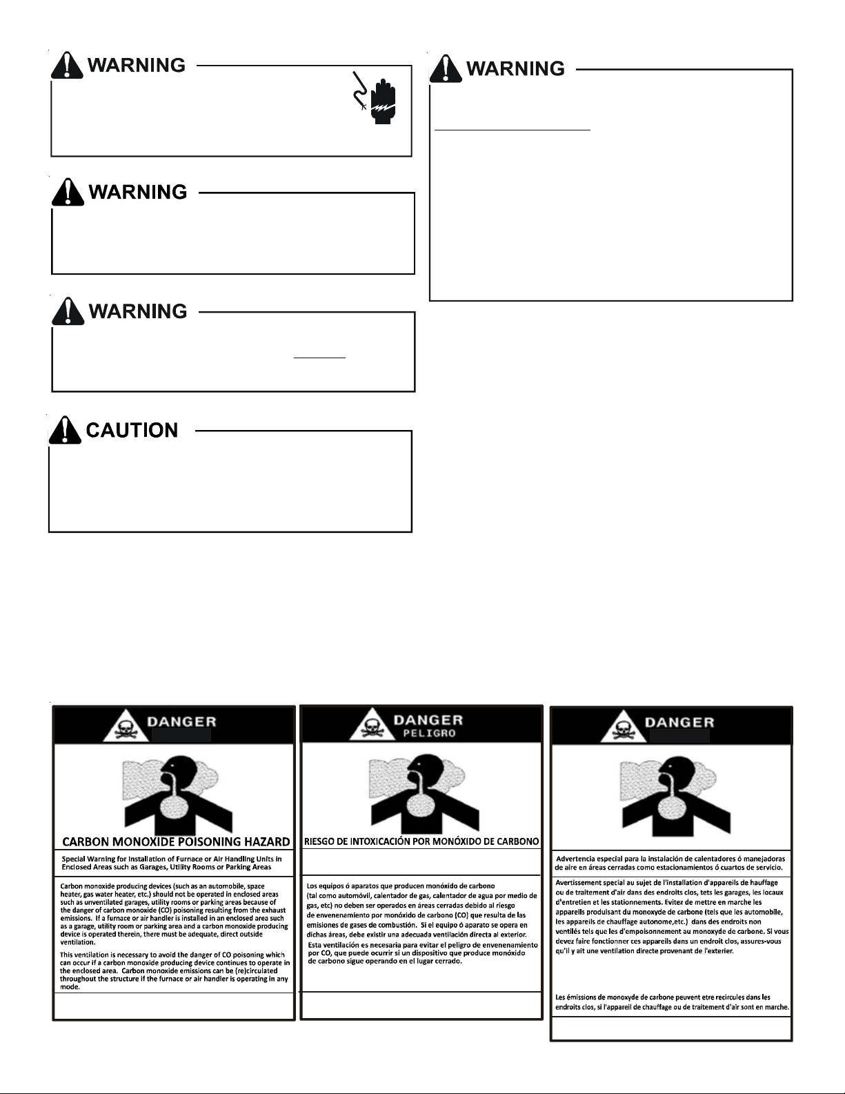
1 Important Safety Instructions
The following symbols and labels are used throughout this
manual to indicate immediate or potential safety hazards.
It is the owner’s and installer’s responsibility to read and
comply with all safety information and instructions accompanying these symbols. Failure to heed safety information
increases the risk of personal injury, property damage, and/
or product damage.
CO can cause serious illness including perm anent bra in
damag e or death.
B10259-216
Advertenci a e spe cia l p ara la instalación de calentadores ó ma nejadoras
de aire en áreas cerradas como estacionamientos ó cuartos de servic io.
Las emis ion es de monóxido de carbono puede n c irc ula r a través
del aparat o c uando se opera en cualquier modo.
El monóx i do de carbono pued e causar enfermedades severas
como daño cerebral permanente ó muerte.
B10259-216
2
RISQUE D'E MPO ISO N NEM EN T AU
Cett e v entilation est nécessaire pour év iter le danger d'intoxication
au CO pouvant survenir si un appareil produisant du monoxyde
de carbon e continue de fonctionner au sei n de l a zone confin é e .
Le monoxyde de
des
dommages permanents au cerveau et meme la mort.
carbone peut causer des maladies graves telles que
MONOXYDE DE CARBONE
B10259-216
Page 3

2 Shipping Inspection
Always transport the unit upright; laying the unit on its side
or top during transit may cause equipment damage. The
installer should inspect the product upon receipt for shipping damage and subsequent investigation is the responsibility of the carrier. The installer must verify the model
number, specifications, electrical characteristics, and accessories are correct prior to installation. The distributor
or manufacturer will not accept claims from dealers for
transportation damage or installation of incorrectly shipped
units.
2.1 Parts
Also inspect the unit to verify all required components
are present and intact. Report any missing components
immediately to the manufacturer or to the distributor.
Use only factory authorized replacement parts (see Section 5). Make sure to include the full product model
number and serial number when reporting and/or obtaining service parts.
2.2 Handling
Use caution when transporting/carrying the unit. Do not
move unit using shipping straps. Do not carry unit with
hooks or sharp objects. The preferred method of carrying the unit after arrival at the job site is to carry via
a two-wheel hand truck from the back or sides or via
hand by carrying at the cabinet corners.
3 Codes & Regulations
This product is designed and manufactured to comply with
applicable national codes. Installation in accordance with
such codes and/or prevailing local codes/regulations is the
responsibility of the installer. The manufacturer assumes
no responsibility for equipment installed in violation of any
codes or regulations.
The United States Environmental Protection Agency (EPA)
has issued various regulations regarding the introduction
and disposal of refrigerants. Failure to follow these regulations may harm the environment and can lead to the
imposition of substantial fines. Should you have any ques-
tions please contact the local office of the EPA and/or refer to EPA’s website www.epa.gov.
4 Replacement Parts
When reporting shortages or damages, or ordering repair
parts, give the complete product model and serial numbers
as stamped on the product. Replacement parts for this
product are available through your contractor or local distributor. For the location of your nearest distributor consult the white business pages, the yellow page section of
the local telephone book or contact:
5 Pre-Installation Considerations
5.1 Preparation
Keep this document with the unit. Carefully read all
instructions for the installation prior to installing product. Make sure each step or procedure is understood
and any special considerations are taken into account
before starting installation. Assemble all tools, hardware and supplies needed to complete the installation.
Some items may need to be purchased locally. Make
sure everything needed to install the product is on hand
before starting.
5.2 System Matches
The entire system (combination of indoor and outdoor
sections) must be manufacturer approved and Air-Conditioning, Heating, and Refrigeration Institute (AHRI)
listed. NOTE: Installation of unmatched systems is not
permitted.
5.3 Interconnecting Tubing
Give special consideration to minimize the length of
refrigerant tubing when installing air handlers. Refer
to Remote Cooling/Heat Pump Service Manual
RS6200006, and TP-107 Long Line Set Application R410A for tubing guidelines. If possible, allow adequate
length of tubing such that the coil may be removed (for
inspection or cleaning services) from the cabinet without disconnecting the tubing.
5.4 Clearances
The unit clearance from a combustible surface may be
0". However, service clearance must take precedence.
A minimum of 24" in front of the unit for service clearance is required. Additional clearance on one side or
top will be required for electrical wiring connections.
Consult all appropriate regulatory codes prior to determining final clearances. When installing this unit in
an area that may become wet (such as crawl spaces),
elevate the unit with a sturdy, non-porous material. In
installations that may lead to physical damage (i.e. a
garage) it is advised to install a protective barrier to
prevent such damage. Always install units such that a
positive slope in condensate line (1/4" per foot) is allowed.
5.5 Horizontal Applications
If installed above a finished living space, a secondary
drain pan (as required by many building codes), must
be installed under the entire unit and its condensate
drain line must be routed to a location such that the
user will see the condensate discharge.
HOMEOWNER SUPPORT
GOODMAN MANUFACTURING COMPANY, L.P.
19001 KERMIER ROAD
WALLER, TEXAS 77484
(877) 254-4729
3
Page 4
6 Installation Location
D
E
NOTE: These air handlers are designed for indoor installa-
tion only.
The ARUF**14** and ASPT**14** product lines may be installed
in one of the upflow, downflow, horizontal left or horizontal right orientations as shown in Figures 2, 3, 4 and 5. The
unit may be installed in upflow or horizontal left orientation as shipped (refer to specific sections for more information).
No field modifications are mandatory. However, to obtain
maximum efficiency, the horizontal drip shield, side drain
pan and drain pan extension can be removed.
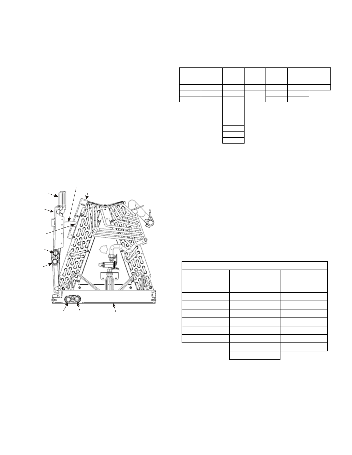
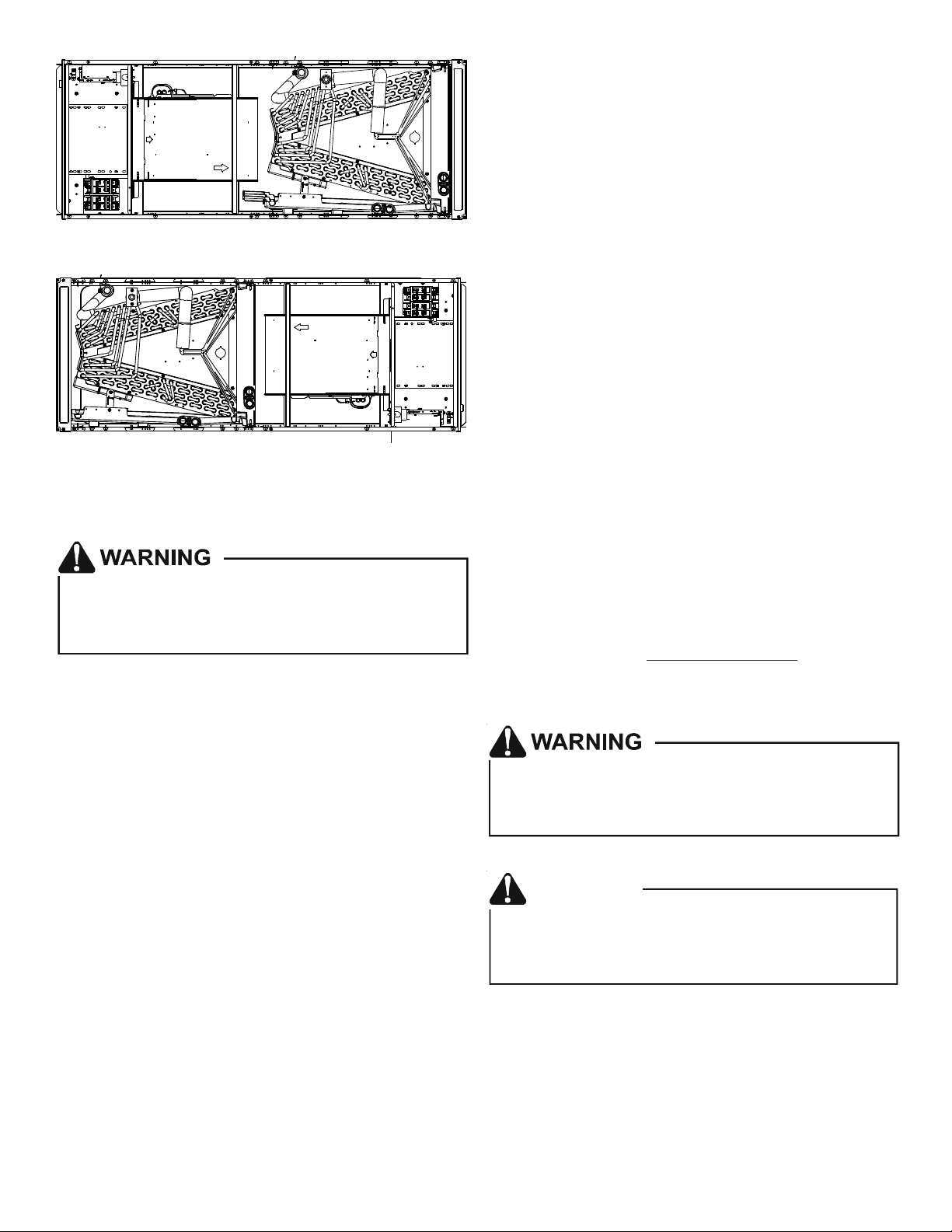
Side Drain Pan and Extension Removal: Refer to Figure 1,
remove the two (2) screws that secure the drip shield support brackets to the condensate collectors (front and back).
Unsnap the side drain pan from the bottom drain pan using
a screw driver or any small lever. The side drain pan, drip
shield brackets and the drain pan extension may now be
removed. From Figure 1, drain port labeled (A) is the primary drain for this application and condensate drain line
must be attached to this drain port. Drain port (a) is for the
secondary drain line (if used).
rip Pan
xtension
Side
Drain
Pan
Screw
Drip Shield Bracket
Drip Shield
In applications where the air handler is installed in the horizontal left position, and the return air environment see
humidity levels above 65% relative humidity coupled with
total external static levels above 0.5” e.s.p., a condensate
kit is available for field application. Kit nomenclature can
be found in Table 1.
Kit
CMK0014
Condensate
Kit
CMK0008
Condensate
ARUF25B14 ARUF31B14 ARUF37C14 ARUF47D14 ARUF61D14 ASPT33C14 ASPT49C14
ARUF29B14 ASPT29B14 ARUF37D14 ASPT49D14 ASPT39C14
ASPT25B14 ASPT37B14 ARUF43C14 ASPT61D14
CMK0009
Condensate
Kit
CMK0010
Condensate
Kit
ARUF43D14
ARUF49C14
ARUF49D14
ASPT37C14
ASPT47C14
ASPT47D14
ASPT59C14
CMK0011
Condensate
Kit
CMK0012
Condensate
Kit
CMK0013
Condensate
Kit
CONDENSATE KIT
Table 1
6.3 Horizontal Right Installation / Downflow
Installation
When installing unit in the downflow position the appropriate (DFK) downflow kit is required to prevent “coil pan
sweating”. The DFK kit is not supplied with the air handler
and is available through your local distributor. See Table 2
for the correct DFK and follow the instructions provided for
installation.
Side drain pan extension must be removed in the downflow
and horizontal right applications for all models except:
ARUF47D14**, ARUF61D14**, ASPT61D14**, ASPT49D14**.
b
B
A
Pna
Main Drain Pan
SIDE DRAIN PAN REMOVAL
Figure 1
6.1 Upflow Installation
No field modifications are mandatory.
6.2 Horizontal Left Installation
No field modifications are permissible for this application.
Install unit as shown in Figure 4.
Remove red plugs from side drain pan before connecting
condensate drain pipes. Use removed plug to close drain
ports on vertical drain pan. The bottom right drain connection in side drain pan is the primary drain for this application and condensate drain line must be attached to this
drain connection. The bottom left drain connection in side
drain pan is for the secondary drain line (if used).
Refer to Figure 6 and 7 for the location of the components referenced in the following steps.
MODEL LIST FOR DOWNFLOW KIT
DFK-B
DOWNFLOW KIT
ARUF25B14** ARUF37C14** ARUF37D14**
ARUF29B14** ARUF43C14** ARUF43D14**
ARUF31B14** ARUF49C14** ARUF47D14**
ASPT25B14** ASPT33C14** ARUF49D14**
ASPT29B14** ASPT37C14** ARUF61D14**
ASPT35B14** ASPT39C14** ASPT61D14**
ASPT37B14** ASPT47C14** ASPT47D14**
1. Before inverting the air handler, remove blower access panel and coil access panel. The coil access panel
and tubing panel may remain screwed together during
this procedure. Remove and retain the seven (7) screws
securing the coil access panel to the cabinet and the
six (6) screws securing the blower access panel to the
cabinet.
DFK-C
DOWNFLOW KIT
DFK-D
DOW NFLOW KIT
ASPT49C14** ASPT49D14**
ASPT59C14**
DOWNFLOW KIT
Table 2
4
Page 5
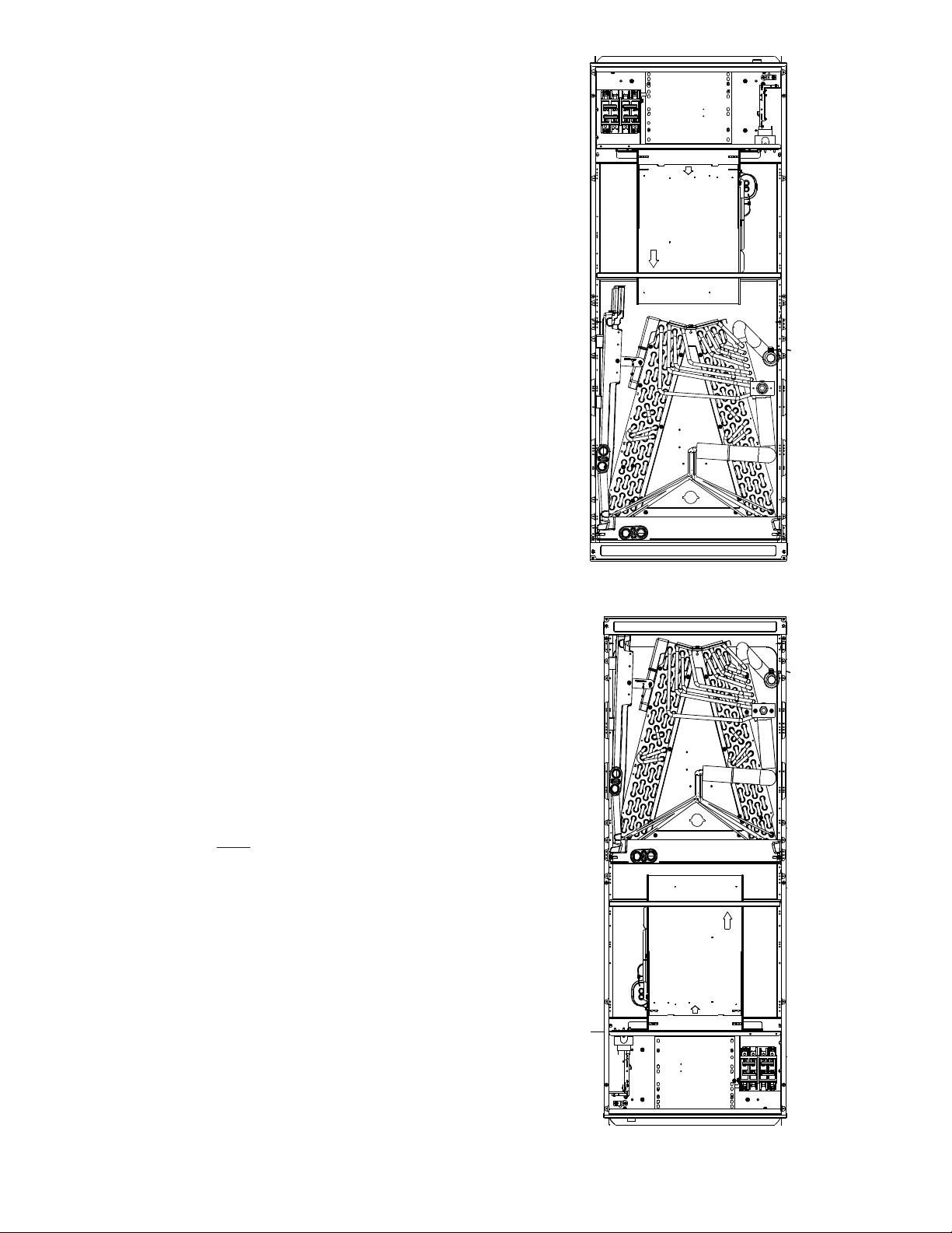
2. Slide the coil assembly out from the cabinet. Use the
drain pan to pull the assembly from the cabinet.
NOTE: DO NOT USE MANIFOLDS OR FLOWRATOR TO
PULL THE COIL ASSEMBLY OUT. FAILURE TO DO SO
MAY RESULT IN BRAZE JOINT DAMAGE AND LEAKS.
3. Removal of the center support is required on units with
21" wide cabinet. Remove and retain the two (2) screws
that secure the center support to the cabinet. Remove
the center support.
4. Position the unit in the downflow position.
5. Using the drain pan to hold the coil assembly, slide the
coil assembly back into the cabinet on the downflow
brackets as shown in Figure 8.
6. Reinstall the center support (if removed) using the two
(2) screws removed in Step 5.
7. Reinstall the coil access panels and reinstall blower
access panel removed in Step 1 as shown in Figure 9.
8. Drain Connections for Horizontal Right Installation
a. The bottom right drain connection in side drain pan
is the primary drain for this application and condensate drain line must be attached to this drain
connection. The bottom left drain connection is
for the secondary drain line (if used).
b. Remove red plugs from side drain pan before con-
necting condensate drain pipes. Use removed plug
to close drain ports on vertical drain pan.
UPFLOW
Figure 2
9. Drain Connections for Downflow Installation
a. The bottom left drain connection in the vertical
drain pan is the primary drain for this application
and condensate drain line must be attached to this
drain connection. The bottom right drain connection is for the secondary drain line (if used).
b. Remove red plugs from vertical drain pan before
connecting condensate drain pipes.
NOTE: If removing only the coil access panel from the unit,
the filter access panel must be removed first. Failure
to do so will result in panel damage.
DOWNFLOW
Figure 3
5
Page 6
HORIZONTAL LEFT
Figure 4
HORIZONTAL RIGHT
Figure 5
7 Refrigerant Lines
This product i s factory-shipped with R410A and dry
nitrogen mixture gas under pressu re. Use appr opria te
service tools and follow these instructions to prevent
injury .
NOTE: Refrigerant tubing must be routed to allow adequate
access for servicing and maintenance of the unit.
7.1 Tubing Size
For the correct tubing size, follow the specification for
the condenser/heat pump.
7.2 Tubing Preparation
All cut ends are to be round, burr free, and clean. Failure to follow this practice increases the chances for
refrigerant leaks. The suction line is spun closed and
requires tubing cutters to remove the closed end.
NOTE: To prevent possible damage to the tubing joints,
do not handle coil assembly with manifold or flowrator
tubes. Always use clean gloves when handling coil assemblies.
7.3 Special Instructions
Units without a factory installed TXV come equipped
with a flowrator piston for refrigerant expansion. For
most installations with matching applications, no
change to the flowrator piston is required. However,
in mix-matched applications, a flowrator piston
change may be required. See the piston kit chart (provided in the literature packet) or consult your local
distributor for details regarding mix-matched
flowrator piston sizing. If the mix-match application
requires a different flowrator piston size, change the
flowrator piston in the flowrator body on the indoor
coil before installing the coil and use the procedure
in section 7.4.
NOTE: The use of a heat shield is strongly recommended
when brazing to avoid burning the serial plate or the
finish of the unit. Heat trap or wet rags must be used
to protect heat sensitive components such as service
valves and TXV valves sensing bulb.
Do not install the air handler in a location that violates the
instructions provided with the condenser. If the unit is
located in an unconditioned area with high ambient
temperature and/or high humidity, the air handler may be
subject to nuisance sweating of the air handler cabinet.
On these installations, a wrap of 2" fiberglass insulation
with a vapor barrier is recommended.
A quenching cloth is strongly recommended to prevent
scorching or marring of the equipment finish when
brazing close to the painted surfaces. Use brazing
alloy of 5% minimum silver content.
CAUTION
Applying too much heat to any tube can melt the tube. Torch
heat required to braze tubes of various sizes must be
proportional to th e s ize of th e tube. S er vice p er sonn el mu st
use the appropriate heat level for the size of the tube being
brazed.
6
Page 7
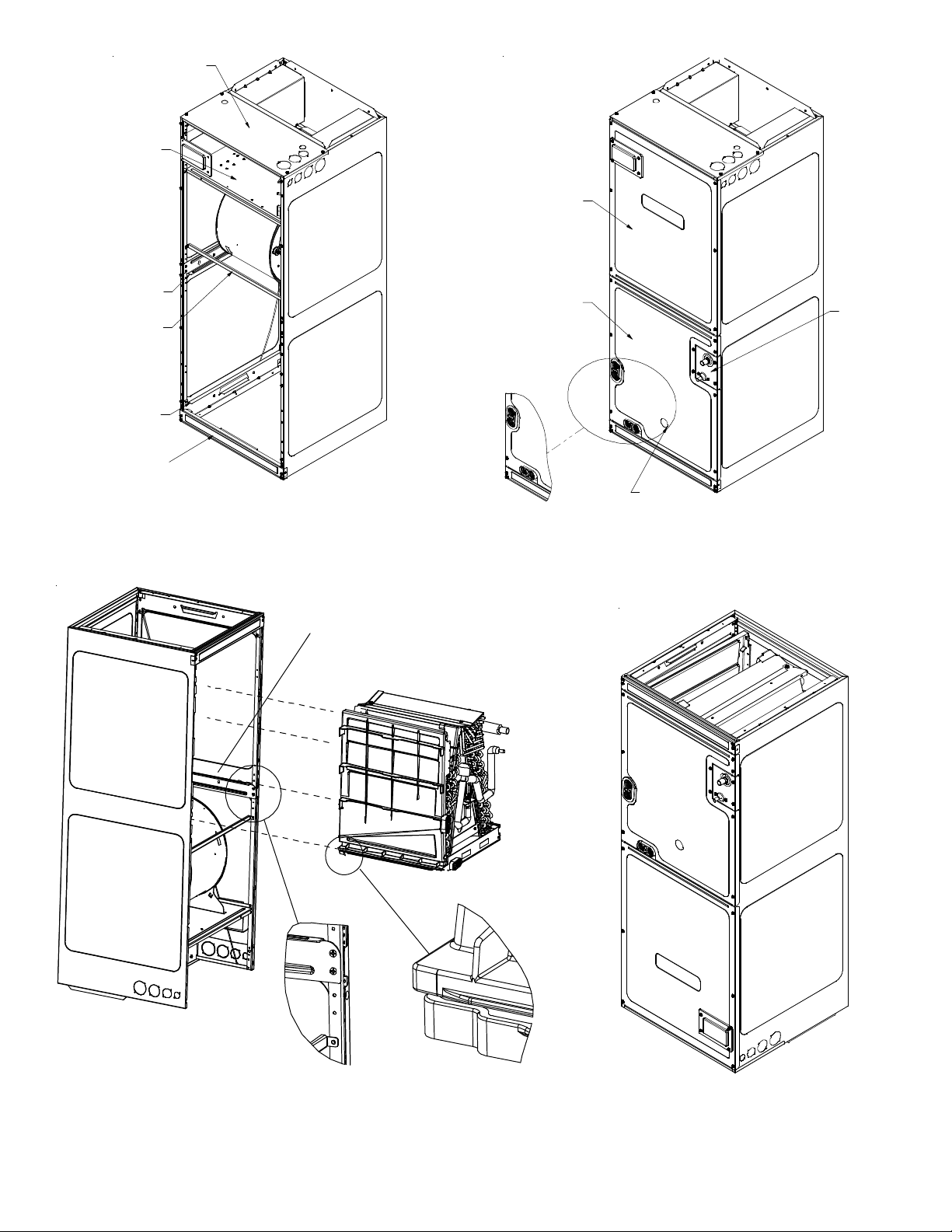
Upper Tie Plate
Control
Deck
Blower
Access
Panel
Downflow
Bracket
Center
Support
Filter
Bracket
Filter
Access
Panel
INTERNAL PART TERMINOLOGY
Figure 6
Coil slides
on the downflow bracket
Coil
Access
Panel
UV
Knockout
EXTERNAL PART TERMINOLOGY
Figure 7
Tubing
Panel
IMPORTANT NOTE:
Ensure coil slides on the rails along the groove provided on the drain pan side
walls. Failure to do so will result in improper condensate drainage.
COIL INSTALLATION FOR DOWNFLOW
Figure 8
7
ACCESS PANEL CONFIGURATION FOR DOWNFLOW
OR HORIZONTAL RIGHT
Figure 9
Page 8
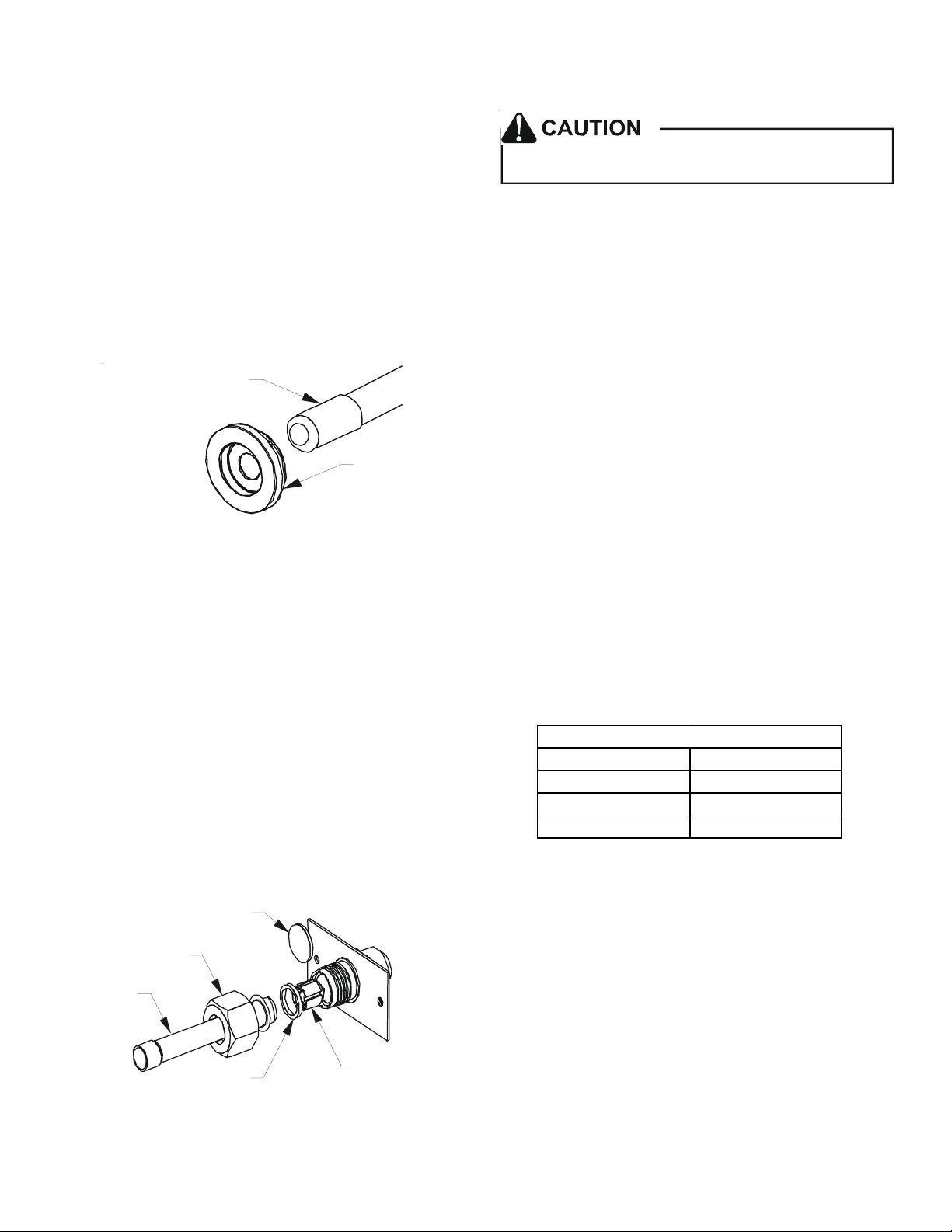
7.4 Tubing Connections for Flowrator Model
1. Loosen the 13/16 nut 1 TURN ONLY to allow high pressure tracer gas to escape. No gas indicates a possible
leak.
9. Torque the 13/16 nut to 7-25 ft-lbs. or tighten 1/6
turn.
2. After the gas has been expelled, remove the nut and
discard the black or brass cap plastic seal.
3. Remove the flowrator piston to verify it is the correct
size for the outdoor unit being installed and then replace the piston (changing size, if needed). See piston
kit chart in the literature kit for appropriate piston
size.
4. Remove the spin closure on the suction line using a
tube cutter and deburr the tube.
SUCTION LINE
WITH SPIN CLOSURE
RUBBER
GROMMET
SUCTION SPUN END AND GROMMET
Figure 10
5. Insert the suction line into the connection, slide the
insulation and the rubber grommet at least 18" away
from the braze joint.
6. Remove the tailpiece clamped to the exterior of the
cabinet or in the literature kit packet and slide the
13/16 nut into place.
Excessive torque can cause orifices to stick. Use the
proper torque settings when tightening orifices.
7.5 Tubing Connections for TXV Models
TXV models come with factory installed TXV with the
bulb pre-installed on the vapor tube.
1. Remove refrigerant tubing panel or coil (lower) access
panel.
2. Remove access valve fitting cap and depress the valve
stem in access fitting to release pressure. No pressure
indicates possible leak.
3. Replace the refrigerant tubing panel.
4. Remove the spin closure on both the liquid and suction
tubes using a tubing cutter.
5. Insert liquid line set into liquid tube expansion and
slide grommet about 18" away from braze joint.
6. Insert suction line set into suction tube expansion and
slide insulation and grommet about 18" away from braze
joint.
7. Braze joints. Quench all brazed joints with water or a
wet rag upon completion of brazing.
7.6 ASPT**14** Models with Non-Adjustable TXV
ASPT air handlers equipped with Parker non-adjustable TXV
should be charged by subcooling only.
7. Braze tailpiece to the line set liquid tube and braze
suction line connection. Quench all brazed joints with
a damp rag upon completion of brazing. Do not allow
water to enter the inside of the tubing.
8. AFTER THE TAILPIECE HAS COOLED, confirm position
of the white Teflon® seal and hand tighten the 13/16
nut.
PLASTIC or BRASS CAP
13/16” NUT
TAILPIECE
WHITE
TEFLON SEAL
TAILPIECE JOINT
Figure 11
PISTON
Models
ASPT25B14** ASPT47D14**
ASPT29B14** ASPT47C14**
ASPT37B14** ASPT49D14**
ASPT37C14** ASPT59C14**
Table 3
See section 7.7 for detailed information on adjusting the
thermal expansion valve.
8
Page 9
7.7 Thermal Expansion Valve System Adjustment
Run the system at Cooling for 10 minutes until refrigerant
pressures stabilize. Use the following guidelines and methods to check unit operation and ensure that the refrigerant
charge is within limits. Charge the unit on low stage.
1. Purge gauge lines. Connect service gauge manifold to
base-valve service ports.
2. Temporarily install a thermometer on the liquid line
at the liquid line service valve and 4-6" from the compressor on the suction line. Ensure the thermometer
makes adequate contact and is insulated for best possible readings. Use liquid line temperature to determine subcooling and vapor temperature to determine
superheat.
3. Check subcooling and superheat. Systems with TXV application should have a subcooling of 7 to 9ºF and superheat of 7 to 9 ºF.
a. If subcooling and superheat are low, adjust TXV to
7 to 9 ºF superheat, then check subcooling.
NOTE: To adjust superheat, turn the valve stem clockwise
to increase and counter clockwise to decrease.
b. If subcooling is low and superheat is high, add charge
to raise subcooling to 7 to 9ºF then check superheat.
c. If subcooling and superheat are high, adjust TXV
valve to 7 to 9 ºF superheat, then check subcooling.
d. If subcooling is high and superheat is low, adjust
TXV valve to 7 to 9 ºF superheat and remove charge to
lower the subcooling to 7 to 9ºF.
NOTE: Do NOT adjust the charge based on suction pressure
unless there is a gross undercharge.
4. Disconnect manifold set, installation is complete.
NOTE: Check the Schrader ports for leaks and tighten valve
cores if necessary. Install caps finger-tight.
SUBCOOL FORMULA =
SAT. LIQUID LINE TEMP. - LIQUID LINE TEMP.
SUPERHEAT FORMULA =
SUCT. LINE TEMP. - SAT. SUCT. TEMP.
NOTE: Expansion valve system in ASPT models are already
tuned for 16 SEER single stage Heat Pump, adjustment of
Expansion valve system is required in case subcool, superheat
does not match to Section 7.6.3 above or when these models
are installed with any other outdoor models.
SATURATED SUCTION PRESSURE
TEMPER AT UR E CH AR T
SUCTION PRESSURE
PSIG R- 22 R- 410A
50 26 1
52 28 3
54 29 4
56 31 6
58 32 7
60 34 8
62 35 10
64 37 11
66 38 13
68 40 14
70 41 15
72 42 16
74 44 17
76 45 19
78 46 20
80 48 21
85 50 24
90 53 26
95 56 29
100 59 31
110 64 36
120 69 41
130 73 45
140 78 49
150 83 53
160 86 56
170 90 60
SATURATED SUCTION
9
Page 10

SATURATED LIQUID PRESSURE
TEMPER ATURE CHART
LIQUID PRESSURE
PSIG R-22 R- 410A
200 101 70
210 105 73
220 108 76
225 110 78
235 113 80
245 116 83
255 119 85
265 121 88
275 124 90
285 127 92
295 130 95
305 133 97
325 137 101
355 144 108
375 148 112
405 155 118
415 157 119
425 n/a 121
435 n/a 123
445 n/a 125
475 n/a 130
500 n/a 134
525 n/a 138
550 n/a 142
575 n/a 145
600 n/a 149
625 n/a 152
SATURATED LIQUID
TEMPER ATURE ºF
separately from the primary drain and end it where condensate discharge can be easily seen.
NOTE: Water coming from secondary line means the coil
primary drain is plugged and needs immediate attention.
CAUTION
If secondary drain is not installed, the secondary
access must be plugged.
Insulate drain lines located inside the building or above a
finished living space to prevent sweating. Install a condensate trap to ensure proper drainage.
NOTE: When units are installed above ceilings, or in other
locations where damage from condensate overflow may
occur, it is MANDATORY to install a field fabricated auxiliary
drain pan under the coil cabinet enclosure.
The installation must include a “P” style trap that is located as close as is practical to the evaporator coil. See
Figure 12 for details of a typical condensate line “P” trap.
NOTE: Units operating in high static pressure applications
may require a deeper field constructed “P” style trap than
is shown in Figure 12 to allow proper drainage and prevent
condensate overflow.
Drain
Connection
Air Handler
POSITI VE LIQUID
SEAL REQUIRED
AT TRAP
2" MIN.
3" MIN.
NOTE: Units matched with indoor coils equipped with nonadjustable TXV should be charged by subcooling only.
8 Condensate Drain Lines
The coil drain pan has a primary and a secondary drain with
3/4" NPT female connections. The connectors required are
3/4" NPT male, either PVC or metal pipe, and should be
hand tightened to a torque of no more than 37 in-lbs. to
prevent damage to the drain pan connection. An insertion
depth of approximately 3/8” to 1/2” (3-5 turns) should be
expected at this torque.
1. Ensure drain pan hole is not obstructed.
2. To prevent potential sweating and dripping on to finished space, it may be necessary to insulate the condensate drain line located inside the building. Use
Armaflex® or similar material.
A secondary condensate drain connection has been provided
for areas where the building codes require it. Pitch all drain
lines a minimum of 1/4" per foot to provide free drainage.
Provide required support to the drain line to prevent bowing. If the secondary drain line is required, run the line
Figure 12
NOTE: Trapped lines are required by many local codes. In
the absence of any prevailing local codes, please refer to
the requirements listed in the Uniform Mechanical Building
Code.
A drain trap in a draw-through application prevents air from
being drawn back through the drain line during fan operation thus preventing condensate from draining, and if connected to a sewer line to prevent sewer gases from being
drawn into the airstream during blower operation.
Use of a condensate removal pump is permitted when necessary. This condensate pump should have provisions for
shutting off the control voltage should a blocked drain occur. A trap must be installed between the unit and the condensate pump.
IMPORTANT NOTE: The evaporator coil is fabricated with
oils that may dissolve styrofoam and certain types of plastics.
Therefore, a removal pump or float switch must not contain
any of these materials.
10
Page 11

Tip: Priming the “P” trap may avoid improper draining at
the initial installation and at the beginning of the cooling
season.
9 Ductwork
This air handler is designed for a complete supply and return ductwork system.
Do not operate this product without all the ductwork
attached.
NOTE: For installations not indicated above the following
formula is to be used:
TR = (kW x 3412) x (Voltage Correction) / (1.08XCFM)
Where: TR = Temperature Rise
kW = Heater Kit Actual kW
3412 = Btu per kW
VC* = .96 (230 Supply Volts)
= .92 (220 Supply Volts)
= .87 (208 Supply Volts)
1.08 = Constant
CFM = Measured Airflow
To ensure correct system performance, the ductwork is to
be sized to accommodate 350-450 CFM per ton of cooling
with the static pressure not to exceed 0.5" in w.c. Refer to
ACCA Manual D, Manual S and Manual RS for information on
duct sizing and application. Flame retardant ductwork is
to be used and sealed to the unit in a manner that will
prevent leakage.
NOTE: A downflow application with electric heat must have
an L-shaped sheet metal supply duct without any outlets or
registers located directly below the heater.
9.1 Return Ductwork
DO NOT LOCATE THE RETURN DUCTWORK IN AN AREA
THAT CAN INTRODUCE TOXIC, OR OBJECTIONABLE
FUMES/ODORS INTO THE DUCTWORK. The return
ductwork is to be connected to the air handler bottom (upflow configuration).
10 Return Air Filters
Each installation must include a return air filter. This filtering may be performed at the air handler using the factory filter rails or externally such as a return air filter grille.
When using the factory filter rails, a nominal 16x20x1”,
20x20x1” or 24x20x1” (actual dimension must be less than
23-½”x20”) filter can be installed on a B, C and D cabinet
respectively (the cabinet size is the seventh letter of the
model number).
11 Electric Heat
Refer to the installation manual provided with the electric
heat kit for the correct installation procedure. All electric
heat must be field installed. If installing this option, the
ONLY heat kits that are permitted to be used are the HKS
series. Refer to the air handler unit’s Serial and Rating plate
or the HKS specification sheets to determine the heat kits
compatible with a given air handler. No other accessory
heat kit besides the HKS series may be installed in these air
handlers.
The heating mode temperature rise is dependent upon the
system airflow, the supply voltage, and the heat kit size
(kW) selected. Use data provided in Tables 4, 5, AND 6 to
determine the temperature rise (°F).
*VC (Voltage Correction)
NOTE: The Temperature Rise Tables can also be used to
estimate the air handler airflow delivery. When using these
tables for this purpose set the room thermostat to maximum
heat and allow the system to reach steady state conditions.
Insert two thermometers, one in the return air and one in
the supply air. The temperature rise is the supply air
temperature minus the room air temperature. Using the
temperature rise calculated, CFM can be estimated from
the TR formula above. See Service Manual for more
information.
HEAT KIT NOMINAL kW
CFM
3568101519/2025
800 1219233137
1000 9 1519253044
1200 8 12152125374962
1400 7 11131821324253
1600 6 9 12 15 19 28 37 46
1800 5 8 10 14 16 25 33 41
2000 5 7 9 12 15 22 30 37
230/1/60 SUPPLY VOLTAGE - TEMP. RISE °F
Table 4
HEAT KIT NOMINAL kW
CFM
3568101519/2025
800 1118223035
1000 9 14 18 24 28 42
1200 7 12 15 20 24 35 47 59
1400 6 10 13 17 20 30 40 51
1600 6 9 111518273544
1800 5 8 101316243139
2000 4 7 9 12 14 21 28 35
11
220/1/60 SUPPLY VOLTAGE - TEMP. RISE °F
Table 5
Page 12

CFM
HEAT KIT NOMINA L k W
3568101519/2025
800 1017212833
1000 8 13 17 22 27 40
1200 7 11 14 19 22 33 45 56
1400 6 10 12 16 19 29 38 48
1600 5 8 101417253342
1800 5 7 9 12 15 22 30 37
2000 4 7 8 11 13 20 27 33
208/1/60 SUPPLY VOLTAGE - TEMP. RISE °F
Table 6
12 Electrical and Control Wiring
IMPORTANT: All routing of electrical wiring must be made
through provided electrical knockouts. Do not cut, puncture or alter the cabinet for electrical wiring.
HIGH VOLTAGE!
Disconnect ALL power before servicing.
Multiple power sources may be present.
Failure to do so may cause property damage,
personal injury or death.
12.1 Building Electrical Service Inspection
This unit is designed for single-phase electrical supply
only. DO NOT OPERATE ON A THREE-PHASE POWER
SUPPLY. Measure the power supply to the unit. The
supply voltage must be measured and be in agreement
with the unit nameplate power requirements and within
the range shown.
12.2 Wire Sizing
Wire size is important to the operation of your equipment. Use the following check list when selecting the
appropriate wire size for your unit.
• Wire used must carry the Minimum Circuit Ampac-
ity (MCA) listed on the unit’s Series and Rating Plate.
• Refer to the NEC (USA) or CSA (Canada) for wire sizing. The unit MCA for the air handler and the optional electric heat kit can be found on the unit Series and Rating Plate.
• Wire must be sized to allow no more than a 2% volt-
age drop from the building breaker/fuse panel to
the unit.
• Wires with different insulation temperature rating
have varying ampacities - be sure to check the temperature rating used.
HIGH VOLTAG E!
T o avoid prope rty dama ge , persona l injury or death
due to el ect rical shock, this unit MU S T have an
uninterrupted, unbroken
electrical ground circuit may consist of an
appro pri at ely sized electrical wire co nnecting the
ground lug in the unit control box to the building
electrical service panel.
Other methods of grounding are permit ted if perform ed
in accordance with the National Electric Code
(NEC) /Americ an Nation al Standar ds Institut e
(ANSI)/National Fire Protection Association (NFP A) 70
and local/state codes. In Canada, electrical grounding
is to be in ac co rda nce w ith th e C ana dian Elec tric Cod e
(CSA) C22.1.
electrical ground. The
Refer to the latest edition of the National Electric
Code or in Canada the Canadian Electric Code when
determining the correct wire size.
12.3 Maximum Overcurrent Protection (MOP)
Every installation must include an NEC (USA) or CEC
(Canada) approved overcurrent protection device.
Also, check with local or state codes for any special
regional requirements.
Protection can be in the form of fusing or HACR style
circuit breakers. The Series and Rating Plate provides the maximum overcurrent device permissible.
NOTE: Fuses or circuit breakers are to be sized larger
than the equipment MCA but not to exceed the MOP.
12
Page 13

MODEL
3 5 6 8 10 15 19 20 25
ARU F25B 14 715 715 715 715 950
ARU F29B 14 715 715 715 715 950
ARU F31B 14 715 715 715 715 875
ARUF37C14 1170 1170 1170 1170 1345 1345
ARUF43C14 1170 1170 1170 1170 1345 1345
ARUF49C14 1170 1170 1170 1170 1340 1430
ARUF37D14 1 170 1170 1170 1170 1345 1345
ARUF43D14 1 170 1170 1170 1170 1345 1345
ARUF47D14 1 170 1170 1170 1170 1345 1345
ARUF49D14 1 240 1240 1240 1240 1520 1520
ARUF61D14 1 590 1590 1590 1590 1715 1715 1715
HEATER KIT (KW)
MINIMUM CFM REQUIRED FOR HEATER KITS
Table 7
Model
HEATER KIT (KW)
3 5 6 8 10 15 19 20 25
ASPT2 5B14 715 715 715 715 850
ASPT2 9B14 715 715 715 715 875 1050
ASPT3 5B14 715 715 715 715 875 1050
ASPT3 7B14 715 715 715 715 875 1050
ASPT3 3C14 715 715 715 715 875 875
ASPT3 7C14 1170 1170 1170 1170 1345 1345
ASPT3 9C14 1170 1170 1170 1170 1345 1345
ASPT4 7C14 1170 1170 1170 1170 1345 1345
ASPT4 9C14 1170 1170 1170 1170 1345 1345
ASPT5 9C14 1170 1170 1170 1170 1345 1345
ASPT4 7D14 1240 1240 1240 1240 1520 1520
ASPT4 9D14 1590 1590 1590 1590 1715 1715 1715
ASPT6 1D14 1590 1590 1590 1590 1715 1715 1715
MINIMUM HEATER KIT AIRFLOW
Table 8
Nominal Input Minimum Voltage Maximum Voltage
208-240 197 253
ELECTRICAL VOLTAGE
Table 9
13
Page 14

12.4 Electrical Connections – Supply Voltage
FIRE HAZARD!
To avoid the risk of property damage, personal injury
or fire, use only copper conductors.
IMPORTANT NOTE: USE COPPER CONDUCTORS ONLY.
Knockouts are provided on the air handler top panel and
sides of the cabinet to allow for the entry of the supply
voltage conductors, as shown in Figure 13. If the knockouts
on the cabinet sides are used for electrical conduit, an
adapter ring must be used in order to meet UL1995 safety
requirements. An NEC or CEC approved strain relief is to be
used at this entry point. Some codes/municipalities require
the supply wire to be enclosed in conduit. Consult your
local codes.
Top of
Cabinet
Side of
Cabinet
12.5 Low Voltage Connections
Several combinations of low voltage schemes are possible, depending on the presence of a heat kit and
whether the heat kit is single-stage or multi-stage,
whether the outdoor section is an air conditioner or
heat pump, and whether the outdoor section is singlestage or two-stage. The 24V-control voltage connects
the air handler to the room thermostat and condenser.
Low voltage wiring must be copper conductors. A minimum of 18AWG must be used for installations up to
100 feet. Low voltage wiring must be connected
through the top of the cabinet or either side. See the
“Thermostat Wiring” section of this manual for typical low voltage wiring connections.
12.5.1 Thermostats
Second-stage heat can be accomplished by a multistage heating thermostat or the addition of an outdoor thermostat as shown in wiring schematics on page
19. Follow the thermostat manufacturer’s instructions for installation.
12.6 Speed Tap Adjustment
ARUF**14** air handlers have multi-speed PSC motors.
The color of the wire coming from the motor to the
“COM” terminal on the control board defines at which
speed the motor will operate. Black wire is high speed,
blue wire is medium speed and red wire is low speed.
To change speeds, remove the wire attached to the
“COM” terminal on the control board, and swap it
with the wire (on terminal “M1” or “M2”) with the
color that will give the desired speed.
KNOCK-OUT FOR ELECTRICAL CONNECTIONS
Figure 13
12.4.1 Air Handler Only (Non-Heat Kit Models)
The building supply connects to the stripped black
and red wires contained in the air handler electrical
compartment cavity. A ground screw is also contained
in this area. Attach the Supply wires to the air handler conductors as shown in the unit wiring diagram
using appropriately sized solderless connectors or
other NEC or CEC approved means.
12.4.2 Air Handler - Non-Circuit Breaker Heat
Kits
A terminal block is provided with the HKS kit to attach the power supply and air handler connections.
Follow the HKS Installation Manual and wiring diagram
for complete wiring details.
12.4.3 Air Handler With Circuit Breaker Heat Kit
The air handler has a plastic cover on the upper access panel that will require either one or both sections to be removed to allow the heat kit circuit
breaker(s) to be installed. The circuit breakers have
lugs for power supply connection. See the HKS Installation Instructions for further details.
ASPT**14** air handlers feature energy efficient blower
motors. The motors run at a constant torque with very
low power consumption and are energized by 24 VAC.
Adjust the CFM by changing the 24 VAC leads to the
desired speed tap on the terminal block. The ASPT
blower motor speeds are programmed to deliver adequate airflow at rated external static pressure and
with 60 second off time delay. For details, refer to
the specification sheet applicable to your model.
NOTE: In some models, not all speed taps are allowable for
certain electric heat applications. Refer to Table 5 for
minimum speed.
14
Page 15

13 Achieving 1.4% Low Leakage Rate
Ensure all the gaskets remain intact on all surfaces as shipped
with the unit. These surfaces are areas between the upper
tie plate and blower access panel, blower access and coil
access panels, and between the coil access and filter access
panels. Ensure upon installation, that the plastic breaker
cover is sitting flush on the blower access panel and all access panels are flush with each other and the cabinet. With
these requirements satisfied, the unit achieves less than 1.4%
airflow leakage when tested in accordance with ASHRAE Standard 193.
14 Start-Up Procedure
15 Regular Maintenance
The only item required to be maintained on a regular basis
by the user is the circulating air filter(s). Filter should be
cleaned or replaced regularly, typically once per month. A
certified service technician must perform all other services.
IMPORTANT NOTE: If thumb screws are used to access the
filter, ensure the washer installed on the screw behind the
access panel remains in place after re-installation.
HIGH VOLTAGE!
Disconnect ALL power before servicing or
installing this unit. Multiple power sources may
be present. Failure to do so may cause property
damage, personal injury or death.
• Prior to start-up, ensure that all electrical wires are
properly sized and all connections are properly tightened.
• All panels must be in place and secured. For Air Tight
application, gasket must be positioned at prescribed
locations to achieve 1.4% leakage.
• Tubing must be leak free.
• Condensate line must be trapped and pitched to allow for drainage.
• Low voltage wiring is properly connected.
• Auxiliary drain is installed when necessary and pitched
to allow for drainage.
• Unit is protected from vehicular or other physical damage.
• Return air is not obtained from, nor are there any return air duct joints that are unsealed in, areas where
there may be objectionable odors, flammable vapors
or products of combustion such as carbon monoxide
(CO), which may cause serious personal injury or death.
15
Page 16

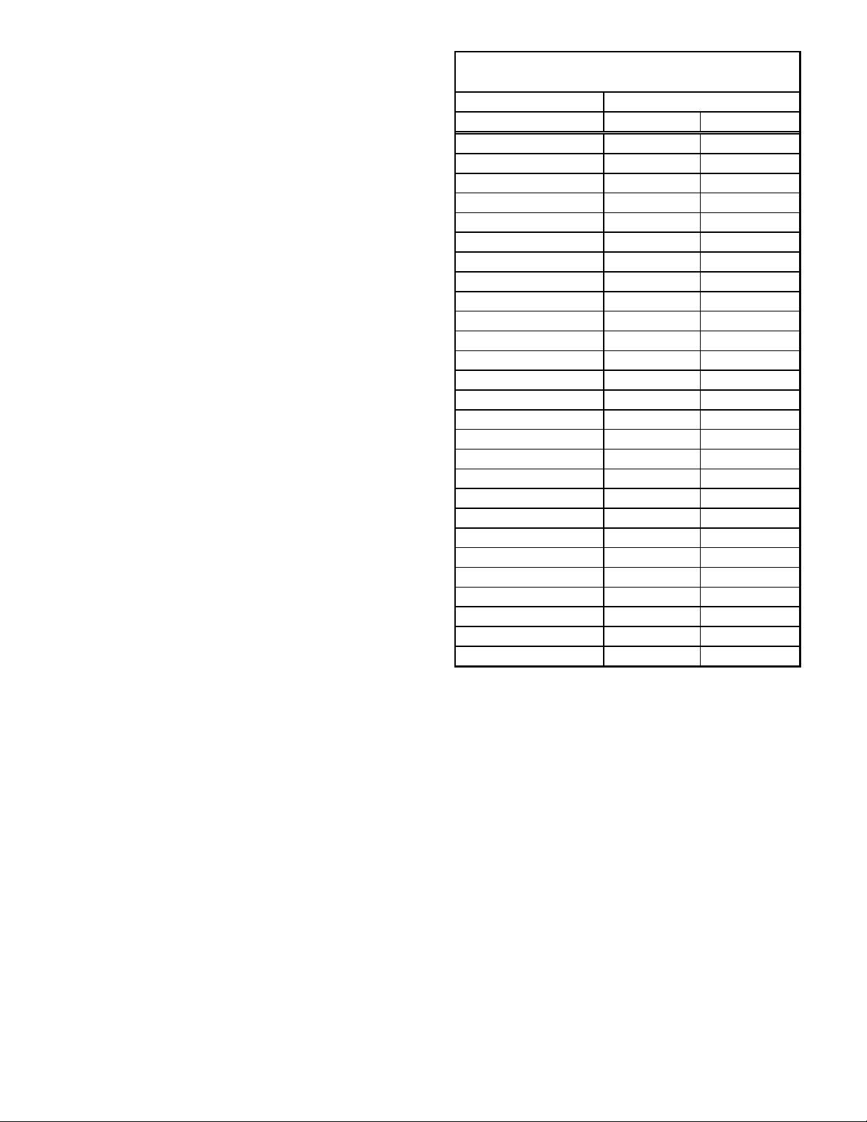
16 Airflow Data
Model
ARUF25B14
ARUF29B14
ARUF31B14
ARUF37C14
ARUF43C14
ARUF49C14
ARUF37D14
ARUF43D14
ARUF47D14
ARUF49D14
ARUF61D14
Notes
1. Airf low data indicated is at 230V without air filter in place.
2. The ch ar t is for i nfor mat io n on l y . F o r sat isf ac to r y o p er ati on , ex ter n al stat ic pr e ssur e m u st n o t ex c eed v alu e sho w n o n
3. Use the CFM adjustment factors of 0.98 for horizontal left and 0.96 f or horizontal rig ht & downflow orientations
Blower
Speed
LOW 650 620 595 540 490 420 275
MED 885 865 825 815 750 690 560
HIGH 1255 1225 11 30 1090 965 925 800
LOW 650 620 595 540 490 420 275
MED 885 865 825 815 750 690 560
HIGH 1255 1225 11 30 1090 965 925 800
LOW 660 625 595 560 500 430 330
MED 930 905 865 820 765 700 590
HIGH 1235 1185 11 30 1060 990 910 825
LOW 1120 1085 1040 1000 940 875 800
MED 1425 1385 13 45 1285 1220 1145 1060
HIGH 1625 1575 15 20 1460 1375 1295 1200
LOW 1120 1085 1040 1000 940 875 800
MED 1425 1385 13 45 1285 1220 1145 1060
HIGH 1625 1575 15 20 1460 1375 1295 1200
LOW 1295 1255 1225 1175 1120 1055 970
MED 1535 1485 14 20 1370 1295 1215 1130
HIGH 1755 1680 15 90 1515 1425 1340 1250
LOW 1155 1115 1070 1015 955 89 5 840
MED 1505 1470 14 30 1375 1300 1210 1105
HIGH 1785 1735 16 80 1625 1555 1440 1330
LOW 1410 1360 1290 1210 1120 1010 920
MED 1610 1540 14 70 1390 1300 1190 1060
HIGH 1900 1830 17 40 1645 1540 1420 1280
LOW 1420 1370 1310 1240 1125 1045 960
MED 1625 1585 15 15 1435 1350 1235 1095
HIGH 1930 1890 18 20 1735 1635 1505 1355
LOW 1410 1360 1290 1210 1120 1010 920
MED 1610 1540 14 70 1390 1300 1190 1060
HIGH 1900 1830 17 40 1645 1540 1420 1280
LOW 1530 1500 1460 1405 1350 1280 115 5
MED 1950 1885 18 30 1785 1745 1670 1595
HIGH 2235 2170 21 00 2030 1965 1915 1825
0.1 0.2 0.3 0.4 0.5 0.6 0.7
Static Pressure (i n w.c) Airfl o w (CFM)
AIRFLOW DATA (CFM) - Table 10
16
Page 17

j
p
y
Model Blower Speed
T1 640 585 580 545 510 490 410 340 280
A SP T25B 14A A
A SP T29B 14A A
A SP T35B 14A A
A SP T37B 14A A
A SP T33C 14A A
A SP T37C 14A A
A SP T39C 14A A
A SP T47C 14A A
A SP T49C 14A A
A SP T59C 14A A
A SP T47D 14A A
A SP T49D 14A A
A SP T61D 14A
T2 800 765 725 700 670 645 595 565 490
T3 840 805 800 760 740 700 670 625 580
T4 985 950 920 885 850 815 800 760 725
T5 1475 1440 1400 1375 1335 1305 1270 1240 1150
T1 595 590 565 530 505 455 380 305 260
T2 790 775 745 705 665 625 585 515 445
T3 865 820 790 770 735 695 645 595 530
T4 1015 980 955 925 880 840 795 770 720
T5 1505 1465 1430 1410 1385 1350 1315 1285 1220
T1 875 845 845 825 795 780 730 680 630
T2 985 945 925 915 905 880 845 795 760
T3 1070 1025 990 985 980 960 940 905 860
T4 1245 1205 1170 1135 1115 1115 1100 1090 1035
T5 1310 1275 1230 1190 1155 1135 1085 1080 1040
T1 1025 985 945 910 875 830 795 735 690
T2 1150 1105 1065 1025 995 950 915 870 825
T3 1240 1200 1160 1120 1085 1050 1010 970 925
T4 1425 1400 1355 1320 1290 1250 1215 1180 1145
T5 1490 1455 1415 1390 1355 1320 1285 1250 1205
T1 865 685 615 540 480 410 335 270 215
T2 935 880 820 785 720 660 600 550 490
T3 1110 1050 1000 955 905 855 795 760 710
T4 1360 1310 1260 1220 1180 1135 1095 1055 1010
T5 1560 1515 1475 1435 1395 1370 1330 1295 1260
T1 980 935 895 860 825 800 755 710 665
T2 1125 1075 1045 1000 965 930 880 845 820
T3 1235 1190 1155 1120 1085 1045 1005 965 920
T4 1485 1450 1425 1390 1355 1315 1275 1230 1190
T5 1565 1535 1510 1480 1240 1390 1365 1320 1280
T1 865 685 615 540 480 410 335 270 215
T2 935 880 820 785 720 660 600 550 490
T3 1110 1050 1000 955 905 855 795 760 710
T4 1360 1310 1260 1220 1180 1135 1095 1055 1010
T5 1560 1515 1475 1435 1395 1370 1330 1295 1260
T1 955 895 855 840 780 735 675 615 560
T2 1100 1050 1005 965 925 870 815 770 705
T3 1205 1160 1120 1075 1035 990 940 885 830
T4 1445 1410 1365 1320 1275 1235 1190 1140 1095
T5 1525 1480 1435 1400 1360 1320 1275 1230 1180
T1 1325 1280 1240 1200 1160 1115 1065 1025 990
T2 1465 1420 1380 1355 1315 1280 1245 1195 1155
T3 1510 1470 1430 1395 1355 1330 1290 1250 1210
T4 1600 1565 1530 1490 1460 1425 1390 1365 1295
T5 1690 1660 1625 1590 1555 1525 1490 1400 1255
T1 1370 1330 1295 1255 1215 1180 1140 1100 1060
T2 1535 1500 1465 1430 1405 1370 1335 1300 1210
T3 1680 1645 1615 1575 1545 1510 1440 1330 1205
T4 1905 1855 1780 1690 1605 1515 1425 1330 1205
T5 1940 1855 1775 1700 1605 1505 1420 1320 1205
T1 1055 1015 950 895 830 785 730 680 620
T2 1210 1165 1110 1070 1015 960 900 840 785
T3 1335 1290 1250 1205 1145 1100 1050 980 910
T4 1625 1580 1530 1495 1455 1405 1350 1295 1230
T5 1720 1670 1625 1580 1540 1490 1435 1390 1325
T1 1485 1435 1380 1320 1265 1200 1230 1015 930
T2 1570 1525 1480 1430 1370 1315 1235 1155 1035
T3 1680 1600 1570 1555 1475 1430 1360 1280 1185
T4 1800 1765 1715 1670 1625 1590 1510 1465 1390
T5 2215 2160 2120 2085 2040 2000 1970 1930 1865
T1 1545 1495 1440 1390 1335 1260 1180 1105 1045
T2 1705 1655 1605 1555 1505 1445 1380 1330 1275
A
T3 1850 1805 1760 1710 1665 1615 1555 1500 1445
T4 2095 2055 2020 1980 1935 1890 1845 1800 1755
T5 2260 2205 2195 2160 2120 2075 2030 1990 1945
Static P ressure (in w.c.) A irflow (C FM)
0.1 0.2 0.3 0.4 0.5 0.6 0.7 0.8 0.9
Notes
1. Airflow data indicated is at 230V without air fi lter in
2. The chart is for informa tion onl
3. U se the CFM ad
ustment fac tors of 0.98 for horizontal left and 0.96 for horizontal right & downflow orientations.
. For satisfactory operation, external static pressure must n ot exceed value sh own on rating plate. Th e shaded area
lace.
ASPT AIRFLOW DATA (CFM) - Table 11
17
Page 18

17 Air Handler Low Voltage Connections
The following composite wiring diagrams detail various configurations in which the air handlers can be used. Examples
include single-stage cooling and heat pump with single or two-stage electric heating. All these configurations can be
applied with convenient connections to outdoor thermostat applications.
The following sections are detailed:
• Single-Stage Cooling
• Heat Pump
Each diagram details the connections between room thermostat and the air handlers, and the connections between the
air handlers and the Condensing Unit (or Heat Pump) with optional connections to Outdoor Thermostats. For each
configuration, refer to the explanation of the proper jumper(s) to remove for the corresponding blower speed that will
result in the programmed fixed speed ECM motor.
IMPORTANT: WHEN MATCHING THE ASPT AIR HANDLERS TO A SINGLE SPEED COOLING OR HEAT
PUMP UNIT, REMEMBER TO CONNECT “Y” FROM THE THERMOSTAT TO THE “Y2” ON THE LOW
VOLTAGE TERMINAL BOARD.
Any equivalent thermostat can be used in place of the manufacturer’s thermostat part number.
18
Page 19

WARNING
HIGH VOLTAGE!
MULTIPLE POWER SOURCES MAY BE PRESENT. FAILURE TO DO SO
MAY CAUSE PROPERTY DAMAGE, PERSONAL INJURY OR DEATH.
DISCO NNECT ALL POWER BEFORE SERVICING.
Low Voltage Wiring for ARUF Air Handlers
ROOM THERMOSTAT
WY
GR
#18 GA. 4 WIRES WITH
COOLING 3 WIRES WITHOUT
ARUF UNIT
R
G
W
Y
CONTACTOR
COIL
TO CON DENSING
UNIT 2 4 V. CONNE CTIONS
#18 GA. 2 WIRES
Low Voltage Wiring Diagram for Cooling Unit with optional heat kit 10KW and below
RED
GREEN
WHITE
BLUE
W2
ARUF UNIT
#18 GA. 4 WIRE WI TH
COO LING 3 WI R E WITHO UT
RED
GREEN
WHITE
#18 GA. 2 WIRES
CONTACTOR
COIL
CONDENSING
UNIT 2 4V. CONNEC TIO N S
BROWN
BLUE
Low Voltage Wiring Diagram for Cooling Unit with optional heat kit 15KW and above
Wiring is subject to change. Always refer to the wiring diagram on the unit for the most up-to-date wiring.
19
Page 20

WARNING
ARUF
10 KW & BELOW
HEAT PUMP
CW2OYR
B
R
I
HIGH VOLTAGE!
DISCO NNECT ALL POWER BEFORE SERVICING.
MULTIPLE POWER SOURCES MAY BE PRESENT. FAILURE TO DO SO
MAY CAUSE PROPERTY DAMAGE, PERSONAL INJURY OR DEATH.
Low Voltage Wiring for ARUF Air Handlers
TYPICAL H/P
ROOM THERMOSTAT
YOC GRE
R
W2
R
R
#18 GA. 7 WIRE
AR UNIT
R
RED
#18 GA. 5 WIRE
(OPTIONAL)
OUTDOOR THERMOST AT
CLOSE ON TEMPERATURE FALL
ARUF
ABOVE 10 KW
HEAT PUMP
W2
C
B
YO R
R
R
I
Y
O
W
BL
ROOM THERMOSTAT
Y CO
R
Y
O
W
NOTE
TYPICAL H/P
W2
NOTE
RGE
BR
G
BR
W
BL
R
G
NOTE
G
GREEN
W
WHITE
BL
BLUE
#18 GA. 6 WIRE NEEDED WHEN OT IS USED
#18 GA. 7 WIRE
AR UNIT
RED
R
GREEN
G
WHITE
W
BROWN
BR
BL
BL
#18 GA. 5 WIRE
(OPTIONAL)
OUTDOOR THERMOST AT
CLOSE ON TEMPERATURE FALL
BL
#18 GA. 7 WIRE NEEDED WHEN TWO OT'S ARE USED
BLUE
Wiring is subject to change. Always refer to the wiring diagram on the unit for the most up-to-date wiring.
20
Page 21

WARNING
HIGH VOLTAGE!
DISCO NNECT ALL POWER BEFORE SERVICING.
MULTIPLE POWER SOURCES MAY BE PRESENT. FAILURE TO DO SO
MAY CAUSE PROPERTY DAMAGE, PERSONAL INJURY OR DEATH.
#18 GA. 4 WIRES WITH COOLING
3 WIRES WITHOUT
YW
GR
AIR HANDLER
C
RD
GR
WH
R
G
W1
W2
Y1
Y2
O
TB
YL
BL
TO CONDENSING UNIT
24V CONNECTION
YL
YL
BL
COOLING UNIT WITH OPTIONAL HEAT KITS OF 10 kW AND BELOW
#18 GA. 5 WIRES WI T H COOLING
4 WIRES WITHOUT
W2
BR
YL
BL
YGW
YL
CONDENSING UNIT
24V CONNECTION
R
BR
RD
GR
WH
BR
YL
YL
BL
AIR HANDLER
C
R
G
W1
W2
Y1
Y2
O
TB
COOLING UNIT WITH OPTIONAL HEAT KITS OF 15 kW AND ABOVE
AND ROOM TH E RMOST AT WITH TWO ST A GES OF H EAT
NOTES:
1) OUTDOOR THERMOSTAT (OT-1) SHOULD BE THE FIRST
TO CLOSE AND THE LAST TO OPEN.
2) JUMPER W1 AND W2 TOGETHER IF OT-2 IS NOT USED.
3) REMOVE WIRE WHEN USING OUTDOOR THERMOSTAT.
NOMENCLATURE:
OT - OUTDOOR THERMOSTAT (OPTIONAL)
EHR - EMERGENCY HEAT RELAY (OPTIONAL)
Wiring is subject to change. Always refer to the wiring diagram on the unit for the most up-to-date wiring.
21
COLOR CODES
RD - RED
YL - YELLOW
BL - BLUE
BR - BROWN
OR - ORANGE
WH - WHITE
Page 22

WARNING
HIGH VOLTAGE!
DISCO NNECT ALL POWER BEFORE SERVICING.
MULTIPLE POWER SOURCES MAY BE PRESENT. FAILURE TO DO SO
MAY CAUSE PROPERTY DAMAGE, PERSONAL INJURY OR DEATH.
#18 GA. 7 WIRE
W2
YC
O
R Y O
W2
GC R
E
AIR HANDLER
GR
BR
BR
RD
WH
YL
OR
BL
BL
YL
C
R
G
W1
W2
Y1
Y2
O
TB
RD
YL
OR
WH
BL
YL
BL
WH
WH
HEAT PUMP UNIT WITH OPTIONAL HEAT KITS OF 10 kW AND BELOW
#18 GA. 7 WIRE
W2
YC
O
R Y O
W2
GC R
E
AIR HANDLER
BR
RD
GR
YL
WH
OR
RD
BL
RD
WH
C
R
G
W1
W2
Y1
Y2
O
TB
WH
RD
YL
OR
BL
YL
OR
OR
GR
WH
BL
WH
OR
BR
HEAT PUMP UNIT WITH OPTIO NA L HEAT KITS O F 15 kW AND A B O VE
NOTES:
1) OUTDOOR THERMOSTAT (OT-1) SHOULD BE THE FIRST
TO CLOSE AND THE LAST TO OPEN.
2) JUMPER W1 AND W2 TOGETHER IF OT-2 IS NOT USED.
3) REMOVE WIRE WHEN USING OUTDOOR THERMOSTAT.
NOMENCLATURE:
OT - OUTDOOR THERMOSTAT (OPTIONAL)
EHR - EMERGENCY HEAT RELAY (OPTIONAL)
Wiring is subject to change. Always refer to the wiring diagram on the unit for the most up-to-date wiring.
22
COLOR CODES
RD - RED
YL - YELLOW
BL - BLUE
BR - BROWN
OR - ORANGE
WH - WHITE
Page 23

WARNING
C
T
P
R
C
P
C
R R
M
L
L
G
T
R
ELECTRONIC BLOWER TIME DELAY RELAY
HIGH VOLTAGE!
MULTIPLE POWER SOURCES MAY BE PRESENT. FAILURE TO DO SO
MAY CAUSE PROPERTY DAMAGE, PERSONAL INJURY OR DEATH.
DISCO NNECT ALL POWER BEFORE SERVICING.
SYSTEM
TRANSFORME
24 VAC
OPTIONAL
SPEEDU
TSTA
XFMR-
K1
PARK TER M INA
M1
120/240VA
MOTO
B13707-35
XFMR-
WIRING DIAGRA
K1
FOR USE WITH
HEAT KI
SPEEDU
The Electronic Blower Time Delay Relay provides power to the blower motor with a delay of 7
seconds after 24VAC is applied to “G”. After 24VAC is removed from “G”, the blower motor
output is de-energized after a delay of 65 seconds.
Normal Time Delays 60Hz 50Hz
Turn On Delay 7.0 SEC.±1% 8.4 SEC. .±1%
Turn Off Delay 65.0 SEC.±1% 78.0 SEC. .±1%
N E UTRA
Field test mode: Shorting the “speedup” quick connect to “C” decrease times as follows:
Speedup Time s 60Hz 50Hz
Turn On Delay 3.0 SEC.±1% 3.6 SEC. .±1%
Turn Off Delay 5.0 SEC.±1% 6.0 SEC. .±1%
Field test mode is cancelled when the “speedup” quick connect to “C” short is removed.
Wiring is subject to change. Always refer to the wiring diagram on the unit for the most up-to-date wiring.
23
Page 24

18 Wiring Diagrams
COPPER POWERSUPPLY
(USERATING PLATE)
USE MIN.75° C FIELD WIRE
0140A00630-A
PLM
PLF
TR
FACTOR YWIRIN G
FIELD WIRING
NOTE
S:
1. RED WIRES TO BE ON TRANSFORMER TER MINAL"3" FOR 240 VOLTS ANDON
TERMINAL "2" FOR 208 VOLTS.
2.SEE C OMPL ETEWIRING DIAG R AMS ININSTALLATION INSTRUCTIONSFOR
PRO PERLO W VOLTAGE WIRING CON NECTION S.
3. "CONFIRM SPEED TAPSELECTION ISAPPROPRIATE FOR APPLICATION. IF
SPEED TAP NEEDS T O BE CHAN GED, CONNECT PURPLEW IRE FROM TERMINAL7
OF CR (TERMINAL 4 OF ALTERN ATE) R ELAY TO APPROPRIATE TAP AT TB”
4. BROWN AND WHITEWIRES ARE USED FOR HEAT KITS ONLY.
5. FUSE: 3A,250V, 3AG AT OSTYLE FUSE. OPTIONAL FUSE 3 AMP CARTRIDGE.
6. LOW VOLTAGE FIELD WIRING TO BEN.E.C CLASS 2WIRES.
RELAY
EVAPORATOR MOTOR
TERMINAL BOARD
R
EM
TB
BK
RD
BLYLBLUE
BLACK
RED
YELLOW
COMPONENT COD E
BROWN
PURPLE
GREEN
PU
BR
GR
FEMALE PLUG CONNECTOR
MALE PLUG CONNECTO R
TRANSFORMER
HIGH VOLTAGE
LOW VOLTA GE
HIGH VOLTA GE
LOW VOLTA GE
PLF
2
COLOR CODE
TR
65 PLM
4
4
24V
5
1
23
EM
W
IRING COD E
208/240 VOLTS
1
1
PLF
PLM
L1
PLM
2
L2
IF REPLACEMENT OF T HE ORI GINALWIRES
SUPPLIEDW ITH THIS ASSEMBLY IS NECESSARY,
USE WIRE THA T CONFORMS T O THE NATIONAL
ELECTRIC C ODE.
FL
FUSE LINK
TL
THERMAL LIMIT
CR
CONTROL RELAY
WHITEWH
LG
N
W2R W1C G 4Y1 OY2 1DH 325
A
B
1
C
EM
2
4
3
5
4
7
CR
1
SEE NOTE 1
U
S
E
C
O
P
P
E
R
W
I
R
E
E
Q
U
I
P
M
E
N
T
G
R
O
U
N
D
B
L
E
M
Y
L
B
L
5
B
K
C
B
K
P
L
F
B
K
1
R
D
2
3
2
4
0
2
4
V
4
123
T
R
R
D
B
L
B
R
4
5
W
H
6
7
8
9
P
L
M
G
R
D
1
2
3
4
5
6
7
8
9
A
B
1
7
4
C
R
S
E
E
N
O
T
E
S
2
&
6
21435
NCG
L
R
D
P
U
B
L
B
R
W
H
B
L
R
D
G
R
R
D
o
r
B
K
B
L
R
D
B
K
R
D
W
2
R
W
1
C
G4Y1O
Y
2
1
D
H
325
R
D
o
r
B
K
P
U
B
R
W
H
O
R
W
H
W
H
B
L
G
R
R
D
o
r
B
K
B
L
L
2
L
1
SEE
NOTE 1
SEE
NOTE 4
1
3
542
ALTERNATE CONTROL RELAY
B
L
P
U
R
D
G
R
W
H
B
L
1
3
2
4
CR
5
ALTERNATE HEAT RELAY
GRND
GROUND
S
E
E
N
O
T
E
S
2
&
6
F
U
S
E
F
U
S
E
TB
TB
ARUF**14**
IF REPLACEMENT OF THE ORIGINAL WIRES
SUPPLIED WITH THIS ASSEMBLY IS NECESSARY
USE WIRE THAT CONFORMS TO THE
NATIONAL ELECTRIC CODE.
NOTES:
1) RED WIRES TO BE ON TRANSFORMER TERMINAL "3" FOR 240 VOLTS
AND ON TERMINAL "2" FOR 208 VOLTS.
2) SEE COMPOSITE WIRING DIAGRAMS IN INSTALLATION INSTRUCTIONS
FOR PROPER LOW VOLTAGE WIRING CONNECTIONS.
3) CONFIRM SPEED TAP SELECTED IS APPROPRIATE FOR APPLICATION.
IF SPEED TAP NEEDS TO BE CHANGED, CONNECT APPROPRIATE
MOTOR WIRE (RED FOR LOW, BLUE FOR MEDIUM, AND BLACK FOR
HIGH SPEED) ON "COM" CONNECTION OF THE EBTDR.
INACTIVE MOTOR WIRES MUST BE CONNECTED TO "M1 OR M2"
ON EBTDR.
4) BROWN AND WHITE WIRES ARE USED WITH HEAT KITS ONLY.
5) EBTDR HAS A 7 SECOND ON DELAY WHEN "G" IS ENERGIZED
AND A 65 SECOND OFF DELAY WHEN "G" IS DE-ENERGIZED.
6) LOW VOLTAGE FIELD WIRING TO BE N.E.C CLASS 2 WIRES.
WARNING
SEE NOTES 2 & 6
WH
BL
RD GR
GR
RD
BL
XFMR-R
RD
XFMR-C
BL
COPPER POWER SUPPLY
(SEE RATING PLATE)
USE MIN. 75C FIELD WIRE
THREE SPEED MOTOR WIRING
HIGH VOLTAGE!
DISCO NNECT ALL POWER BEFORE SERVICING.
MULTIPLE POWER SOURCES MAY BE PRESENT. FAILURE TO DO SO
MAY CAUSE PROPERTY DAMAGE, PERSONAL INJURY OR DEATH.
TERMINAL BLOCK SHOWN
FOR 50HZ MODELS ONLY
BR
SR
BR
WH
SEE NOTE 5
G
EBTDR
R
K1
K1
C
M1
SPEEDUP
BK
(SELECT MODELS ONLY)
SEE NOTE 3
COM
M2
NO
NC
SEE
NOTE 3
PLF
PLM
PU
(COM) RD
(M2)
(M1)
(TR 1)
PU
L1
L2
RD
BK
2
1
23
1
PU
BK
RD
BK
RD
PU
RD
LOW
BL
MEDIUM
BK
HIGH
PU
BR
3 SPEED
RC
GRD
3
C
EM
4
4
BL
12
24V
5
BL
EQUIPMENT GROUND
USE COPPER WIRE
5 67
5WH67
BR
NOTE 4
RD
SEE NOTE 1
3
240
TR
4
BL
RD
RD
RC
BR
BR
SEE
8 9
89
PU
BK
EM
EBTDR
BK
RD
YL
BL
EM
RC
SR
R
EBTDR
COLOR COD
COMPONENT
L1
PLF
1
PLM
1
RC
1
TR
R
4
RD
E
BLACK
GR
RED
YELLOW
BLUE
GREEN
PU
PURPLE
BROWN
BR
WHITEWH
CODE
EVAPORATOR MOTOR
RUN CAPACITOR
STRAIN RELIEF
RELAY
ELECTRONIC BLOWER
TIME DELAY RELAY
EM
2
24V
WH6BR
3
5
5
208/240
VOLTS
4
PLF
3
NC
M1
HI
M2
LO
SEE NOTE 1
BL
CODE
W
IRING
FACTORY WIRING
HIGH VOLTAGE
LOW VOLTAGE
FIELD WIRING
HIGH VOLTAGE
LOW VOLTAGE
TRANSFORMER
TR
FEMALE PLUG CONNECTOR
PLF
PLM
MALE PLUG CONNECTOR
FL
FUSE LINK
TL
THERMAL LIMIT
EBTDR
COM
EBTDR
PLF
PLM
NO
L2
2
2
GC
GR
0140A00242-A
ASPT**14**
Wiring is subject to change. Always refer to the wiring diagram on the unit for the most up-to-date wiring.
24
Page 25

WARNING
3-Phase Heat Kit
HIGH VOLTAGE!
MULTIPLE POWER SOURCES MAY BE PRESENT. FAILURE TO DO SO
MAY CAUSE PROPERTY DAMAGE, PERSONAL INJURY OR DEATH.
DISCO NNECT ALL POWER BEFORE SERVICING.
Wiring is subject to change. Always refer to the wiring diagram on the unit for the most up-to-date wiring.
25
Page 26

AIR HANDLER
AIR HANDLER HOMEOWNER’S ROUTINE MAINTENANCE RECOMMENDATIONS
REPLACE OR CLEAN FIL TER
IMPORTANT NOTE: Never operate unit without a filter installed as dust and lint will build up on internal parts resulting in
loss of efficiency, equipment damage and possible fire.
An indoor air filter must be used with your comfort system. A properly maintained filter will keep the indoor coil of your
comfort system clean. A dirty coil could cause poor operation and/or severe equipment damage.
Your air filter or filters could be located in your furnace, in a blower unit, or in “filter grilles” in your ceiling or walls. The
installer of your air conditioner or heat pump can tell you where your filter(s) are, and how to clean or replace them.
Check your filter(s) at least once a month. When they are dirty, replace or clean as required. Disposable type filters
should be replaced. Reusable type filters may be cleaned.
You may want to ask your dealer about high efficiency filters. High efficiency filters are available in both electronic and
non-electronic types. These filters can do a better job of catching small airborne particles.
MOTORS
Indoor and outdoor fan motors are permanently lubricated
and do not require additional oiling.
ALUMINUM INDOOR COIL CLEANING
(QUALIFIED SERVICER ONLY)
This unit is equipped with an aluminum tube evaporator
coil. The safest way to clean the evaporator coil is to simply flush the coil with water. This cleaning practice remains as the recommended cleaning method for both copper tube
and aluminum tube residential evaporator coils.
It has been determined that many coil cleaners and drain pan tablets contain corrosive chemicals that can be harmful to
aluminum tube and fin evaporator coils. Even a one-time application of these corrosive chemicals can cause premature
aluminum evaporator coil failure. Any cleaners that contain corrosive chemicals including, but not limited to, chlorine
and hydroxides, should not be used.
An alternate cleaning method is to use one of the products listed in TP-109* to clean the coils. The cleaners listed are the
only agents deemed safe and approved for use to clean round tube aluminum coils. TP-109 is also available on the web
site in Partner Link > Service Toolkit.
NOTE: Ensure coils are rinsed well after use of any chemical cleaners.
BEFORE YOU CALL YOUR SERVICER
• Check the thermostat to confirm that it is properly
set.
• Wait 15 minutes. Some devices in the outdoor unit or
in programmable thermostats will prevent compressor operation for awhile, and then reset automatically. Also, some power companies will install devices which shut off air conditioners for several minutes on hot days. If you wait several minutes, the
unit may begin operation on its own.
• Check the electrical panel for tripped circuit breakers or failed fuses. Reset the circuit breakers or replace fuses
as necessary.
• Check the disconnect switch near the indoor furnace or blower to confirm that it is closed.
• Check for obstructions on the outdoor unit . Confirm that it has not been covered on the sides or the top. Remove
any obstruction that can be safely removed. If the unit is covered with dirt or debris, call a qualified servicer to
clean it.
• Check for blockage of the indoor air inlets and outlets. Confirm that they are open and have not been blocked by
objects (rugs, curtains or furniture).
• Check the filter. If it is dirty, clean or replace it.
• Listen for any unusual noise(s), other than normal operating noise, that might be coming from the outdoor unit. If
you hear unusual noise(s) coming from the unit, call a qualified servicer.
26
Page 27

This page left blank intentionally.
27
Page 28

CUSTOMER FEEDBACK
We are very interested in all product comments.
Please fill out the feedback form on one of the following links:
Daikin Products: (https://daikincomfort.com/contact-us)
Goodman® Brand Products: (http://www.goodmanmfg.com/about/contact-us).
Amana® Brand Products: (http://www.amana-hac.com/about-us/contact-us).
You can also scan the QR code on the right for the product brand you purchased
to be directed to the feedback page.
PRODUCT REGISTRATION
Thank you for your recent purchase. Though not required to get the protection of the
standard warranty, registering your product is a relatively short process, and entitles you to
additional warranty protection, except that failure by California and Quebec residents to
register their product does not diminish their warranty rights.
For Product Registration, please register as follows:
Daikin Products:
(https://daikincomfort.com/owner-support/product-registration).
Goodman® Brand products: (https://www.goodmanmfg.com/product-registration).
Amana® Brand products: (http://www.amana-hac.com/product-registration).
You can also scan the QR code on the right for the product brand you purchased
to be directed to the Product Registration page.
NOTE: SPECIFICATIONS AND PERFORMANCE DATA LISTED HEREIN ARE SUBJECT TO CHANGE WITHOUT NOTICE
Visit our website at www.daikincomfort.com, www.goodmanmfg.com or www.amana-hac.com for information on:
• Products
• Warranties
• Customer Services
• Parts
• Contractor Program and Training
• Financing Options
5151 San Felipe, Suite 500, Houston, TX 77056
© 2014-2017 Goodman Manufacturing Company, L.P.
is a registered trademark of Maytag Corporation or its related companies and is used under license. All rights reserved.
DAIKIN
GOODMAN® BRAND
AMANA® BRAND
GOODMAN® BRAND
DAIKIN
AMANA® BRAND
28
 Loading...