

Page 1
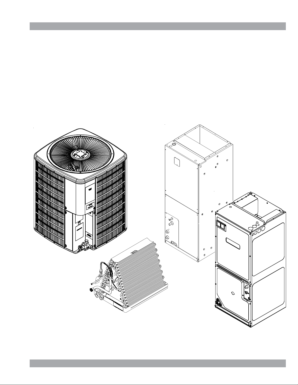
Service Instructions
ANX, SSX, ASX, GSX, DSX, ASXC, DSXC
Condensing Units,
ANZ, SSZ, ASZ, GSZ, DSZ, ASZC, DSZC, VSX, VSZ
Split System Heat Pumps
with R-410A Refrigerant
Blowers, Coils, & Accessories
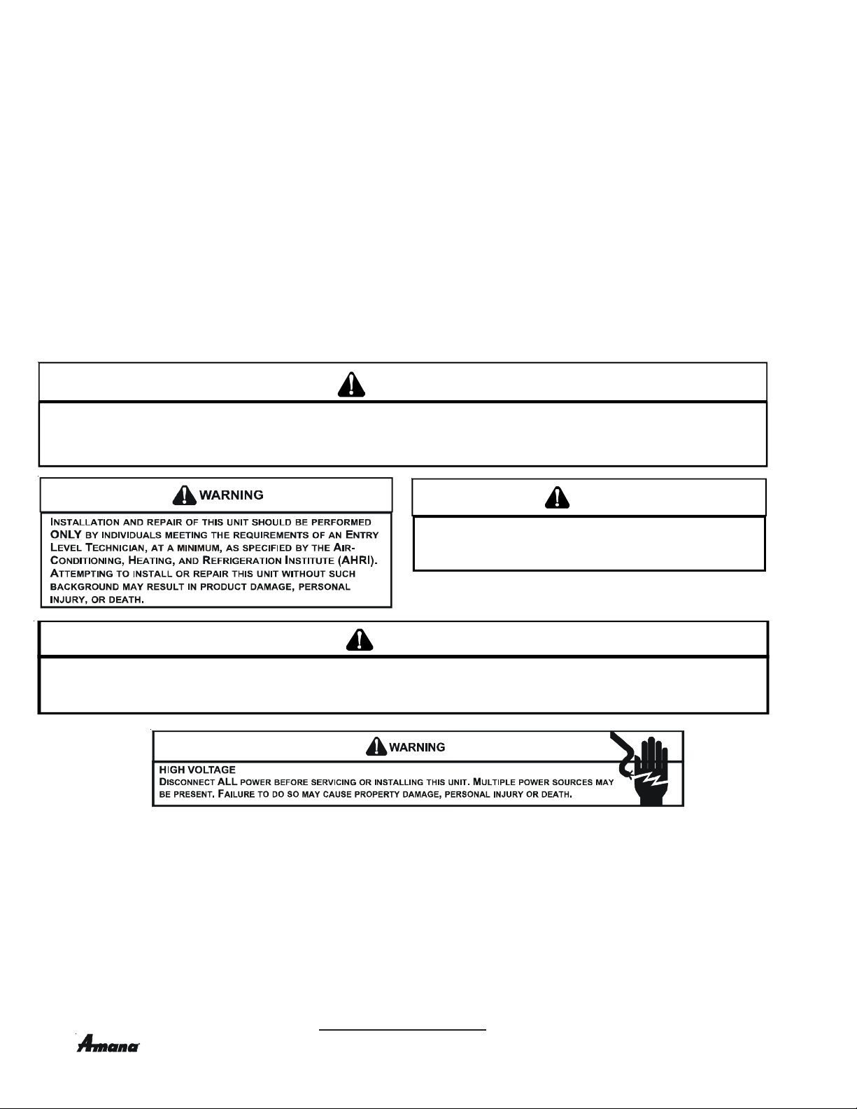
This manual is to be used by qualified, professionally trained HVAC technicians only. Goodman
does not assume any responsibility for property damage or personal injury due to improper
service procedures or services performed by an unqualified person.
Copyright © 2006 - 2015 Goodman Manufacturing Company, L.P.
RS6200006r61
January 2015
Page 2
IMPORTANT INFORMATION
IMPORTANT INFORMATION ............................................... 2 - 3
PRODUCT IDENTIFICATION............................................ 4 - 32
PRODUCT IDENTIFICATION (LIGHT COMMERCIAL)...33 - 34
ACCESSORIES (LIGHT COMMERCIAL) ............................... 35
ACCESSORIES ...............................................................36 - 56
PRODUCT DESIGN ........................................................57 - 59
SYSTEM OPERATION .....................................................60 - 64
TROUBLESHOOTING CHART .............................................. 65
SERVICE TABLE OF CONTENTS ......................................... 66
SERVICING .................................................................. 66 - 168
ACCESSORIES WIRING DIAGRAMS ......................... 169- 179
WIRING DIAGRAMS..........................................................180 -321
Pride and workmanship go into every product to provide our customers with quality products. It is possible, however, that
during its lifetime a product may require service. Products should be serviced only by a qualified service technician who is
familiar with the safety procedures required in the repair and who is equipped with the proper tools, parts, testing instruments
and the appropriate service manual. REVIEW ALL SERVICE INFORMATION IN THE APPROPRIATE SERVICE MANUAL BEFORE
BEGINNING REPAIRS.
IMPORTANT NOTICES FOR CONSUMERS AND SERVICERS
RECOGNIZE SAFETY SYMBOLS, WORDS AND LABELS
WARNING
THIS UNIT SHOULD NOT BE CONNECTED TO. OR USED I N CONJUNCTI ON WITH, ANY DEVICES THAT ARE NOT DESI GN CERTIFI ED FOR USE WITH THIS UNIT OR HAVE NOT BE EN
TESTED AND APPROVED BY
FROM THE USE OF DEVICES THAT HAVE NOT BEEN APPROVED OR CERTI FED BY
OODMAN. SERIOUS PROPERTY DAMAGE OR PERSONAL INJURY, REDUCED UNIT PERFORMANCE AND/OR HAZARDOUS CONDITIONS MAY RESULT
G
OODMAN.
G
WARNING
T
O PREV ENT THE RI SK OF PR OPERT Y DAMA GE, PE RSO NAL IN JURY, OR DE ATH,
DO NOT STORE COMBUSTIBLE MATERIALS OR USE GASOLINE OR OTHER
FLAMMABLE LIQUIDS OR VAPORS IN THE VICINITY OF THIS APPLIANCE.
WARNING
OODMA N W ILL NOT BE R ESPONSIBLE FOR A NY IN JURY O R PRO PERTY DAMAGE ARI SING FRO M IMPR OPER SERVICE O R SER VICE P ROCEDU RES.
G
IF YO U INSTALL OR PE RFORM SERVIC E ON THIS UNIT, YOU ASSUME RE SPONSIBILITY FOR ANY PERSON AL INJURY OR P ROPERTY DA MAGE WH ICH
MAY RESULT.
ANY JURISDICTIONS REQUIRE A LICENSE TO INSTALL OR SERVICE HEATING AND AIR CONDITIONING EQUIPMENT.
M
To locate an authorized servicer, please consult your telephone book or the dealer from whom you purchased this product.
For further assistance, please contact:
CONSUMER INFORMA TION LINE
GOODMAN® BRAND PRODUCTS
TOLL FREE
1-877-254-4729 (U.S. only)
email us at: customerservice@goodmanmfg.com
fax us at: (713) 856-1821
(Not a technical assistance line for dealers.)
email us at: customerservice@goodmanmfg.com
AMANA® BRAND PRODUCTS
TOLL FREE
1-877-254-4729 (U.S. only)
fax us at: (713) 856-1821
(Not a technical assistance line for dealers.)
Outside the U.S., call 1-713-861-2500.
(Not a technical assistance line for dealers.) Your telephone company will bill you for the call.
is a registered trademark of Maytag Corporation or its related companies and is used under license to Goodman Company, L.P., Houston, TX. All rights reserved.
2
Page 3
IMPORTANT INFORMATION
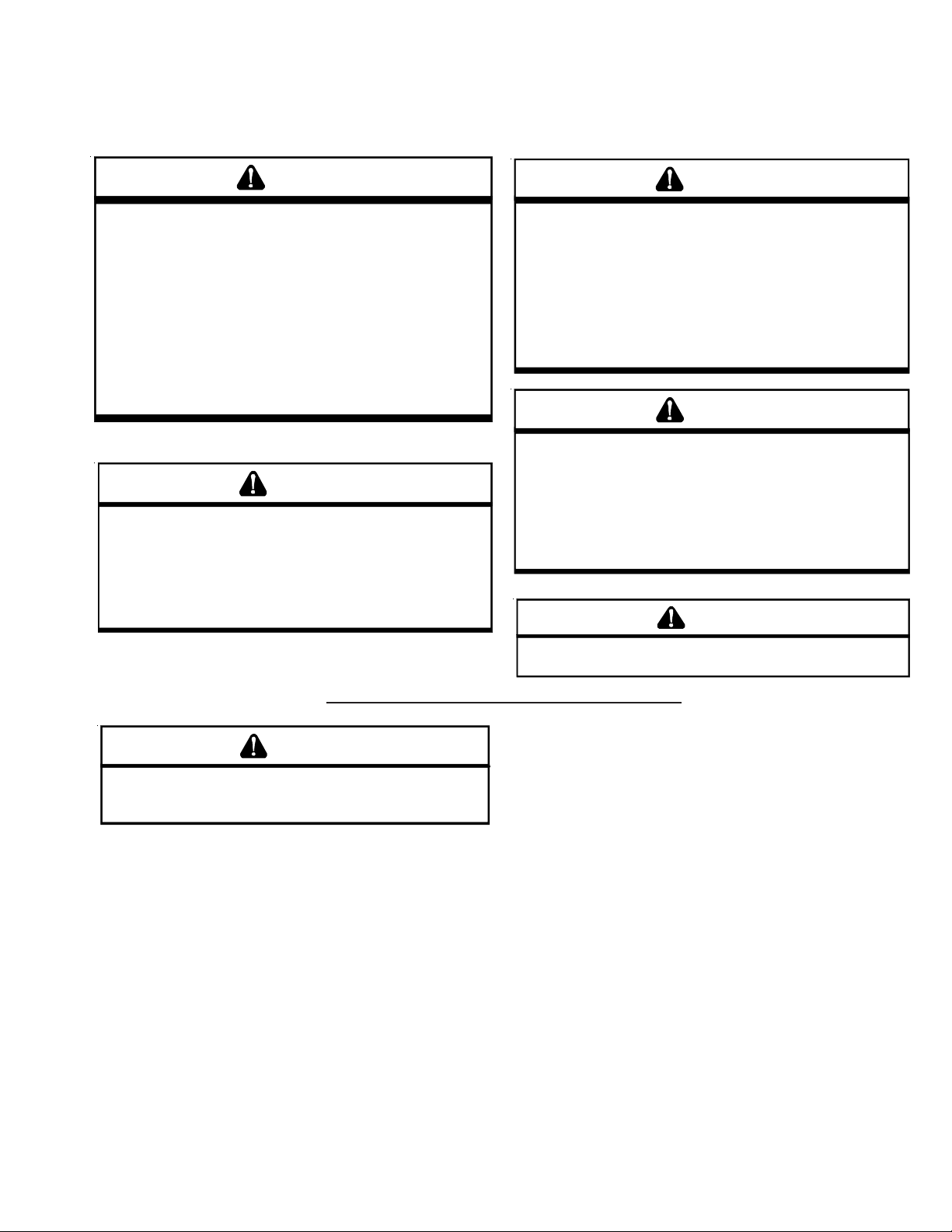
SAFE REFRIGERANT HANDLING
While these items will not cover every conceivable situation, they should serve as a useful guide.
WARNING
EFRIGERANTS ARE HEAVIER THAN AIR. THEY CAN "P USH OUT" TH E
R
OXYGEN IN YOUR LUNGS OR IN ANY ENCLOSED SPAC E.
POSSIBL E DI FFI CULT Y IN BR EAT HING O R DEA TH:
EVER PUR GE REFRIG ERANT INT O AN ENCLO SED ROOM OR SPACE. BY
•
N
LAW, ALL REF RIGERANTS MUST BE REC LAIMED.
F AN INDOOR LEAK IS SUSPECTED, THOROUGHLY VENTILATE THE AREA
•
I
BEFORE BEGINNING WORK.
IQUI D REFRIGE RANT CAN BE VERY COLD . TO AVOID POSSIBLE FROST-
•
L
BITE OR BLINDNESS, AVOID CONTACT W ITH REFRIGERANT AND WEAR
GLOVES AND GOGGLES.
SKI N OR E YES, S EEK M EDI CA L HE LP IMME DI AT ELY .
LWAYS FOLLOW
•
A
AS POISON OUS GAS WI LL BE PRODUC ED.
IF LIQUID REFRIGERANT DOES CONTACT YOUR
REGULA TIONS . NEVER BURN REFRIGERAN T,
EPA
O AVO ID
T
WARNING
HE UNITED STATES ENVIRONMENTAL PROTECTION AGENCY ("
T
HAS ISS UED VARI O US RE G ULAT ION S R EGAR DING THE I NTR OD UCTI ON AND
DISPO SAL OF RE FRI GERANTS INTR ODUCED INTO T HIS U NIT.
FOLLO W THESE REGULAT IONS M AY HAR M THE E NVIRON MENT AND CAN
LEAD TO THEH IMPOSITION OF SUBSTANTIAL FINES.
MAY VARY BY JURISDICTION.
EPA
OFFICE.
LOCAL
HOULD QU ESTIONS ARISE , CONT ACT YO UR
S
HESE REGULATIONS
T
EPA
AILURE TO
F
WARNING
TO AVOID POSSIBLE EXPLOSION:
• NEVER APPLY FLAME OR STEAM TO A REFRIGERANT CYLINDER. IF YOU
MUST H EAT A CYLIN DER FOR FAS TER CHARG ING, PAR TIALLY IMME RSE
IT IN W ARM WATER.
• NEVER FILL A CYLINDER MORE THAN 80% FULL OF LIQUID REFRIGERANT.
NEVER ADD ANYTHING OTHER TH AN R-22 TO AN R-22 CYLINDER OR
•
R-410A TO AN R-410A CYLIND ER. THE SERVICE EQUIPMENT USED MUST
BE LISTED OR CERTIFIED FOR THE TYPE OF REFRIGERANT USED.
TORE CYLINDERS IN A COOL, DRY PLACE. NEVER USE A CYLINDER
•
S
AS A PL ATFORM OR A ROL LER.
WARNING
O AVOID POSSI BLE EXP LOSI ON, US E ONLY R ETURNAB LE ( NOT DIS POSA BLE)
T
SERVICE CYLINDERS WHEN REMOVING REFRIGERANT FROM A SYSTEM.
•
NSURE THE CY LINDER IS FREE OF DAMAGE WHI CH COULD LEAD TO A
E
LEAK OR EXPLOSION.
•
NSURE THE HYD ROSTATI C TES T DATE D OES NOT EXCEE D 5 YEA RS.
")
E
•
NSURE THE PRESSURE RATING MEETS OR EXCEEDS 400 LBS.
E
HEN IN DOUBT, DO NOT USE CYLINDER.
W
WARNING
WARNING
YSTEM CONTAMINANT S, IMPROPER SERVICE PROCEDU RE AND/OR PHYSICAL
S
ABUSE AFFECTING HE RMETIC COMPRESSOR ELECTRICAL TERMINALS MAY
CAUSE DANGEROUS SYSTEM VENTING.
The successful development of hermetically sealed refrigeration compressors has completely sealed the compressor's
moving parts and electric motor inside a common housing,
minimizing refrigerant leaks and the hazards sometimes
associated with moving belts, pulleys or couplings.
Fundamental to the design of hermetic compressors is a
method whereby electrical current is transmitted to the
compressor motor through terminal conductors which pass
through the compressor housing wall. These terminals are
sealed in a dielectric material which insulates them from the
housing and maintains the pressure tight integrity of the
hermetic compressor. The terminals and their dielectric
embedment are strongly constructed, but are vulnerable to
careless compressor installation or maintenance procedures and equally vulnerable to internal electrical short
circuits caused by excessive system contaminants.
T
O AVOID POSSIBLE INJURY, EXPLOSION OR DEATH, PRACTICE SAFE
HANDLING OF REFRIGERAN TS.
In either of these instances, an electrical short between the
terminal and the compressor housing may result in the loss
of integrity between the terminal and its dielectric embedment. This loss may cause the terminals to be expelled,
thereby venting the vaporous and liquid contents of the
compressor housing and system.
A venting compressor terminal normally presents no danger
to anyone, providing the terminal protective cover is properly
in place.
If, however, the terminal protective cover is not properly in
place, a venting terminal may discharge a combination of
(a ) hot lubricating oil and refrigerant
(b ) flammable mixture (if system is contaminated
with air)
in a stream of spray which may be dangerous to anyone in the
vicinity. Death or serious bodily injury could occur.
Under no circumstances is a hermetic compressor to be
electrically energized and/or operated without having the
terminal protective cover properly in place.
See Service Section S-17 for proper servicing.
3
Page 4
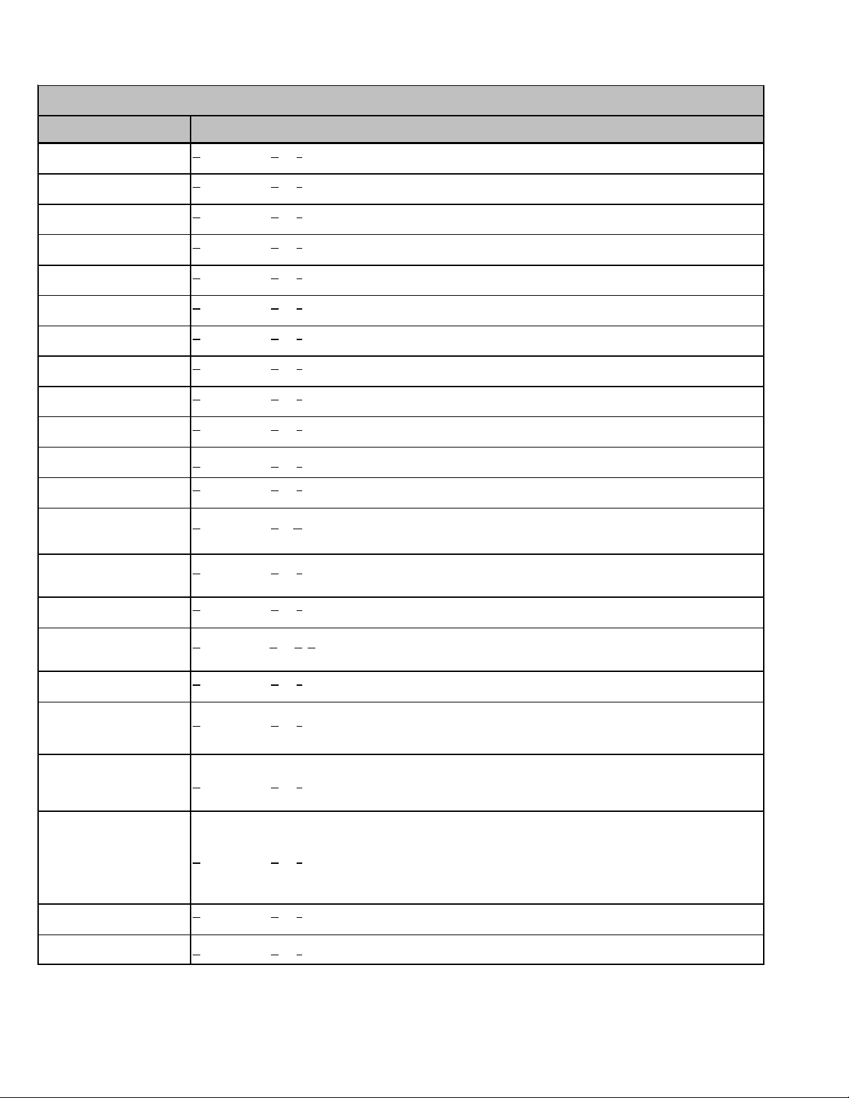
PRODUCT IDENTIFICATION
Spli t Syst em Heat Pumps R410A
Mode l # Description
A
ASZ130**1AA
ASZ130**1AB
ASZ130[18, 36-60]1AB
ASZ130[24-30]1AC
ASZ130[18, 36-60]1AC
ASZ130[24-30]1AD
ASZ130[18, 36-60]1AD
ASZ130[24-30]1AE
ASZ130241BA
ASZ130181AF
ASZ130[24-30]1AG
ASZ130481AF
ASZ140**1AA
ASZ140**1AB
ASZ140**1AC A
mana® Brand Split Z R410A heat pump 13 Seer heat pump unit s. Initial releas e of Amana® Brand 13 SEER Heat
Pump R410A.
mana® Brand Split Z R410A heat pump 13 Seer heat pump unit s. Introduces new revisions wit h im porved circuiting
A
for effective defrost .
A
mana® B rand Split Z R410A heat pump 13 Seer heat pump units. Introduces m odels containing c rankcase heater,
CCH switch and upgraded defrost control.
A
mana® B rand Split Z R410A heat pump 13 Seer heat pump units. Relocat i on of low pressure switch from liquid line
to suction line as a compressor safeguard to prevent low press ure from entering.
mana® B rand Split Z R410A heat pump 13 Seer heat pump units. Initial release of models using singl e s peed P S C
A
motors; rem oval of low ambient temperature switch.
A
mana® B rand Split Z R410A heat pump 13 Seer heat pump units. Release of 2 Ton models, c onverting from 3/8" to
5mm condenser coils
A
mana® Brand Split Z R410A heat pump 13 Seer heat pump unit s. Current reversing valve change from Dunan to
new SanHua reversing valve
mana® Brand Split Z R410A heat pump 13 Seer heat pump unit s. Current Ranco reversing valve 0151M00020
A
replaced by SanHua 0151R00070 reversing valve
A
mana® B rand Split Z R410A heat pump 14 S eer heat pump unit s. Init ial release of A mana® B rand 14 SEER Heat
Pump R410A.
mana® B rand Split Z R410A heat pump 14 S eer heat pump unit s. Introduces new revisi ons have screw loc ati ons
A
moved in the top panel, base pans, louvers, and control box covers .
mana® B rand Split Z R410A heat pump 14 S eer heat pump unit s. New revisions have horizontal style louvers.
ASZ140[18, 42-48]1AD
ASZ140[24-36, 60]1AE
ASZ140361AF
ASZ140421AD
ASZ140[48-60]1AE
ASZ140[18, 30, 36]1AF
ASZ140241AG
ASZ14[42, 48, 60]1AE
ASZ140241AF
ASZ140[18,30,36]1AG
ASZ140241AH
ASZC160[42,48,60]1AF
ASZ140361BA
ASZ140[18, 30]1AH
ASZ140241AJ
ASZ140[42-60]1AG
ASZ140[ 18, 30]1AJ
ASZ140241AK
ASZ140[42-60]1AH
ASZ140361BB
ASZ140181AL
ASZ140241AM
ASZ140301AL
ASZ140361BC
ASZ140381AB
ASZ140[42-60]1AK
ASZ140381AA
ASZ140[18-30]1BA A
Amana® Brand Split Z R410A heat pump 14 Seer heat pump units. Adds new s t eel m uffler, and suc tion tubes
w/shock loop.
A
mana® B rand Split Z R410A heat pump 14 S eer heat pump unit s. New revisions replace TXV & c ompens at or wit h
flowrato r & accum u lator.
mana® B rand Split Z R410A heat pump 14 S eer heat pump unit s. New revisions wil l have Sanhua (RANCO)
A
revers i n g valves.
A
mana® B rand Split Z R410A heat pump 14 S eer heat pump unit s. A F revision has the smaller B 1227315 reversi ng
valve.
A
mana® brand Split Z Communic ati ng heat pum p, 14 Seer R410A heat pum p unit s. Introduces A m ana 14 S E E R
heat pumps with accumul ators, c rank c ase heaters, and upgraded defrost control.
A
mana® B rand Split Z R410A heat pump 14 S eer heat pump unit s. Init ial release of A mana® B rand 14 SEER Heat
Pump R410A, with reduced chassis s i ze from large to medium.
A
mana® B rand Split Z R410A heat pump 14 Seer heat pump units. Relocat i on of low pressure switch from liquid line
to suction line as a compressor safeguard to prevent low press ure from entering.
Amana® Brand Split Z R410A heat pump 14 Seer heat pump unit s.
Amana® Brand Split Z R410A heat pump 14 Seer heat pump unit s. Revision made for design improvement.
mana® B rand Split Z R410A heat pump 14 Seer heat pump units. 35" c hassis with 6-channel flowrator and ZP29K5
A
compressor.
mana® B rand Split Z R410A heat pump 14 Seer heat pump units. Updating ratings and agency information.
4
Page 5
PRODUCT IDENTIFICATION
Split System Heat Pumps R410A
Model # Description
A
ASZ160**1AA
ASZ160**1AB
ASZ160**1AC
ASZ160**1AD
ASZ160241AD
ASZ160[36-60]AE
ASZ160[24, 36]1AF
ASZ160[48, 60]1AF
ASZ160[24,36,48,60]1KA A
ASZ180**1AB
ASZ180[36, 48, 60]1AC
mana® Brand Split Z R410A heat pump 16 Seer heat pump units. Initial release of Amana® Brand 16
SEER Heat Pump R410A.
mana® Brand Split Z R410A heat pump 16 Seer heat pump units. Introduces new revis ions have screw
A
locations m oved in the top panel, base pans, louvers , and control box c overs .
A
mana® Brand Split Z R410A heat pump 16 Seer heat pump units. New revis ions have horizontal s t y le
louvers.
A
mana® Brand Split Z R410A heat pump 16 Seer heat pump units. New revis ions added Muffl er and
standardized TXV, Compensat or using the AS Z18 Seer weldment.
mana® Brand Split Z R410A heat pump 16 Seer heat pump units. A dds new st eel muffler, and suction
A
tubes w/s hock l oop.
mana® Brand Split Z R410A heat pump 16 Seer heat pump units. New revisions will have Sanhua
A
(RANCO) reversing valves.
mana® Brand Split Z R410A heat pump 16 Seer heat pump units.
A
mana® Brand Split Z R410A heat pump 18 Seer heat pump units. Initial release of Amana® Brand 18
SEER Heat Pump R410A.
mana® Brand Split Z R410A heat pump 18 Seer heat pump units. New revisions will have Sanhua
A
(RANCO) reversing valves.
Split System Heat Pumps R410A
Model # Description
ANZ130[18-60]1AA
ANZ130[18/24/30]1AB
ANZ130481AB
A
mana® Brand Split S y s t em B ase Heat P ump, 13 Seer R-410A units.
A
mana® Brand Split S y s t em B ase Heat P ump, 13 Seer R-410A units. Current reversi ng valve c hange from
Dunan to new SanHua reversing valve
A
mana® Brand Split S y s t em B ase Heat P ump, 13 Seer R-410A units. Current Ranco reversing valve
0151M00020 replaced by SanHua 0151R00070 reversi ng val ve
5
Page 6
PRODUCT IDENTIFICATION
Split System Heat Pumps R410A
Mo d e l # Descr iptio n
mana® brand Split Z Communi cating heat pump, 16 S eer R410 A heat pump units. I ntroduc es Go odm an 2-
ASZC160**1AA
A SZC 16 0[2 4, 36 ]1A B
A SZC 16 0[4 8, 60 ]1A B
ASZC160[24-48]1AC
ASZC160601BA
ASZC160[24-36]1AD
ASZC160601BB
ASZC160[24-36]1AE
ASZC160481AE
ASZX180601BC
ASZC180**1AA
ASZC180[36, 48, 60]1AB
ASZC180[36-48]1AC
ASZC180601BA
ASZC180361AD
ASZC180481AD
ASZX180601BB
A
stage 16 SEER heat pumps wi th R-410A, com municating models.
mana® brand Split Z Communicating heat pump, 16 Seer R410A heat pump units. New revisions will have
A
Sanhua (R ANC O) revers i ng v alves.
A
mana® brand Split Z Communic ating heat pump, 16 Seer R410A h eat pump units. Introduces A ma na 2-
stage 16 SE ER heat pumps with accumulators and crankca s e heaters.
A
mana® brand Split Z Communic ating heat pump, 16 Seer R410A heat pump units. Change motor to Nidec.
mana® brand Split Z Communi cating heat pump, 16 S eer R410 A heat pump units. I New revis ion rep laces
A
existing compressor ZPS20K4EPFV230 to ZPS20 K5EPFV130 & existing compressor ZPS30K4EPFV230 to
ZPS30K5EPFV130.
mana® brand Split Z Communicating heat pump, 18 Seer R410A heat pump units. Introduces Ul tratech
A
2.0®.
A
mana® brand Split Z Communi cating heat pump, 18 S eer R410 A heat pump units. I ntroduc es Go odm an 2-
stage 16 SEER heat pumps wi th R-410A, com municating models.
mana® brand Split Z Communi cating heat pump, 18 S eer R410 A heat pump units. I ntroduc es Amana 2-
A
stage 16 SE ER heat pumps with accumulators and crankca s e heaters.
mana® brand Split Z Communicating heat pump, 18 Seer R410A heat pump units. New revisions will have
A
Sanhua (R ANC O) revers i ng v alves.
A
mana® brand Split Z Communicating heat pump, 18 Seer R410A heat pump units. New revisions will have
Sanhua (R ANC O) revers i ng v alves.
mana® brand Split Z Communicating heat pump, 18 Seer R410A heat pump units. Introduces Ul tratech
A
2.0®.
6
Page 7
PRODUCT IDENTIFICATION
Split System Heat Pumps R410A
Model # Descript io n
D
DSZ160**1AA
DSZ160241AC
DSZ16036, 48, 60]1AB
DSZ180**1AA
DSZ180[36, 48 , 6 0]1AB
DSZC16**1AA
DSZC 160[ 24, 36] 1AB
DSZC 160[ 48, 60] 1AB
DSZC160[24-48]1AC
DSZC160601BA
eluxe Spl it Z Heat Pump 16 Seer heat pum p units. Intro duce s Good m an 2- st age 16 SEE R heat pumps with
R-410A.
D
eluxe Split Z Heat P ump 16 Seer heat pum p uni ts. Goodman 2-stag e 16 S EER heat pumps with R-410A .
New revisions will have Sanhua (RANCO) reversing valves.
eluxe Spl it Z Heat Pump 18 Seer heat pum p units. Intro duce s Good m an 2- st age 18 SEE R heat pumps with
D
R-410A.
D
eluxe Split Z Heat P ump 18 Seer heat pum p uni ts. Goodman 2-stag e 18 S EER heat pumps with R-410A .
New revisions will have Sanhua (RANCO) reversing valves.
D
eluxe Split Z Commun icating heat pum p, 16 Seer R410A heat pump units. Intr oduces Goodman 2 -stage 16
SEER heat pu mps w it h R- 41 0A, co mmuni cating mo de l s.
D
eluxe Split Z Co mmunic ating hea t pump, 16 Se er R41 0A heat pump units. G oodman 2-stage 16 SEER
he at pu m ps wi th R-410A, communic ating mod els . New revi sions wi ll hav e Sanhua ( RANC O) rever sing
valves.
D
eluxe Split Z Commun icating heat pum p, 16 Seer R410A heat pump units. Intr oduces Goodman 2 -stage 16
SEE R heat pumps with accumulators and crankcase hea ters.
DSZC160[24-48]1AD
DSZC160601BB
DSZC160[24-36]1AE
DSZC160481AE
DSZC160601BC
DSZC18**1AA
DSZC180[36, 48, 60]1AB
DSZC180[36-48]1AC
DSZC180601BA
DSZC180361AD
DSZC160[24-48]1AD
DSZC160601BB
D
eluxe Spl it Z Commun icating heat pum p, 16 Seer R410A heat pump units. Intr oduces Ultratech 2.0®
compressor changes.
eluxe Spl it Z Commun icating hea t pump, 16 Se er R41 0A heat pump units. New r evision replaces exis ting
D
compr essor ZPS20K4EPFV230 to Z PS20K5E PFV130 & existing compressor ZPS30K 4EPFV2 30 to
D
eluxe Split Z Commun icating heat pum p, 16 Seer R410A heat pump units. Intr oduces Ultratech 2.0®
compressor changes.
D
eluxe Split Z Commun icating heat pum p, 18 Seer R410A heat pump units. Intr oduces Goodman 2 -stage 18
SEER heat pu mps w it h R- 41 0A, co mmuni cating mo de l s.
D
eluxe Split Z Co mmunic ating hea t pump, 18 Se er R41 0A heat pump units. G oodman 2-stage 18 SEER
heat pum ps with R - 410A, communicating mod els. New revisions w ill have S anhua (R ANCO) re versing
valves.
eluxe Spl it Z Commun icating heat pum p, 18 Seer R410A heat pump units. Intr oduces Goodman 2 -stage 18
D
SEE R heat pumps with accumulators and crankcase hea ters.
D
eluxe Split Z Commun icating heat pum p, 18 Seer R410A heat pump units. New revision replaces existin g
compr essor ZPS20K4EPFV230 to Z PS20K5E PFV130 & existing compressor ZPS30K 4EPFV2 30 to
ZPS30K5EPFV130.
D
eluxe Spl it Z Commun icating heat pum p, 16 Seer R410A heat pump units. Intr oduces Ultratech 2.0®
compressor changes.
7
Page 8
PRODUCT IDENTIFICATION
Split Syst em Heat Pumps R410A
Model # Description
GSZ13**1AA G
GSZ13**1AB
GSZ13**3AA
GSZ13**4AA
GSZ130 [24 & 30 ]1A C
GSZ130 [24 & 36 ]1B A
GSZ130241CA
GSZ130241CB
GSZ130[18, 42-60]1AC
GSZ130301AD
GSZ130361BB
GSZ130[18,42,48,60]1AD
GSZ130301AE
GSZ130[36,48,60{3,4]AB
GSZ130[48,60{3,4]AB
GSZ130[18,42,48]1AF
GSZ130301AG
GSZ130[36,48]3AD
GSZ130484AC
oodman Split Z R410A Heat Pump 13 Seer heat pump units. Initi al release with Regal Beloit m otor.
oodman Split Z R410A Heat Pump 13 Seer heat pump units. Initi al release with B road Ocean motor.
G
oodman Split Z R410A Heat Pump 13 Seer heat pump units. Introduces new revi s i ons wit h im proved
G
circuiting for effecti ve defrost.
G
oodman Split Z R410A Heat Pump 13 Seer heat pump units. Initi al release of models wit h 5mm Sm art
Coil™.
Goodman Split Z R410A Heat Pump 13 Seer heat pump units. Release of 2 Ton models with a
compress or c hange from ZP 21K5E P FV130 t o ZP20K5EPF V130.
oodman Split Z R410A Heat Pump 13 Seer heat pump units. 2 Ton models changing from the current
G
four pi ec e louver as s em bly , t o a two piece louver pl us a c orner post on Goodman and value series 26" and
29" chassis.
oodman Split Z R410A Heat Pump 13 Seer heat pump units. Introduces m odels c ont aining c rankc as e
G
heater, CCH switch and upgraded defrost control.
oodman Split Z R410A Heat Pump 13 Seer heat pump units. Relocation of low pres s ure swit c h from
G
liquid line to suction li ne as a com press or safeguard to prevent low pressure from entering.
oodman Split Z R410A Heat Pump 13 Seer heat pump units. Changing from the c urrent four piece louver
G
ass embly , t o a two piece louver pl us a c orner post on Goodman and value series 26" and 29" chas s is .
GSZ130361BC
GSZ130 [42 & 48 ]1A E
GSZ130361BD
GSZ130421AF
GSZ130 [36 & 48 ]3A C
GSZ14**1AA G
GSZ130481AG
GSZ130483AE
GSZ130484AD
oodman Split Z R410A Heat Pump 13 Seer heat pump units. Release of models with new 6 pole
G
motor/fan combinati on.
oodman Split Z R410A Heat Pump 13 Seer heat pump units. Models wit h new 6 pole motor/fan
G
combinati on. Changing from the current four pi ece l ouver as s embly, t o a two piece louver plus a corner
post on G oodm an and value series 26" and 29" chassis.
oodman Split Z R410A Heat Pump 13 Seer heat pump units. Release of two piece louver plus corner
G
post on 26" and 29" chas s is with compressor changing from ZP36K 5EP F V130 to ZP34K5EP F V130.
oodman Split Z R410A Heat Pump 13 Seer heat pump units. Release of 3 phase models with new 6
G
pole motor.
oodman Split Z R410A Heat Pump 14 Seer heat pump units. Initial release of 14 SEER models.
oodman Split Z R410A Heat Pump 13 Seer heat pump units. Current Ranco reversing valve 0151M00020
G
replaced by SanHua 0151R00070 reversing valve
8
Page 9
PRODUCT IDENTIFICATION
Split System Heat Pumps R410A
Mode l # Description
pecial High Feature Split Z R410A heat pump 14 Seer heat pump units. Initial release of Goodman 14 SEER Heat
SSZ140**1AA
SSZ140**1AB
SSZ140**1AC S
S
Pump R410A.
pecial High Feature Split Z R410A heat pump 14 Seer heat pump units. Introduces new revisions have screw
S
locat i ons m oved in the top panel, base pans, l ouvers, and control box covers.
pecial High Feature Split Z R410A heat pump 14 Seer heat pump units. Models contain Broad Ocean mot ors .
SSZ140181AC
SSZ140241AF
SSZ140301AD
SSZ140361AF
SSZ140421AD
SSZ140[48-60]1AD
SSZ140[18, 30, 42-60]1AE
SSZ140241AH
SSZ14036]1AG
SSZ140[18,30,42-60]1AF
SSZ140241AJ
SSZ160361AH
SSZ140[18 & 30]1A H
SSZ140241AL
SSZ140361BB
SSZ140[18 & 30]1A J
SSZ140[19,25,31,37]1AC
SSZ140241AM
SSZ140361BC
SSZ140381AB
SSZ140[42-60]1AH
SSZ140241AG
SSZ140[18-60]1AD S
SSZ140361AF
SSZ140421AD
SSZ140[48-60]1AD
SSZ140381AA
SSZ140[18-30]1BA S
pecial High Feature Split Z R410A heat pump 14 Seer heat pump units. Introduces new revisions adding mufflers to
S
the dis charge line.
pecial High Feature Split Z R410A heat pump 14 Seer heat pump units. New revisions replace TXV & compensator
S
with flowrator & acc um ulat or; adds m ufflers on SSZ14036`, 421, 481, 601.
pecial High Feature Split Z R410A heat pump 14 Seer heat pump uni ts. New revisions will have Sanhua (RA NCO)
S
reversing valves.
pecial High Feature Split Z R410A heat pump 14 Seer heat pump units. Introduces m odels containing an
S
accumulator, c rankcase heater, and upgraded defros t cont rol.
pecial High Feature Split Z R410A heat pump 14 Seer heat pump units. Changing from the current four piece louver
S
assembly, to a two piece louver plus a corner post on Goodman and value s eries 26" and 29" chassi s .
pecial High Feature Split Z R410A heat pump 14 Seer heat pump units. Revision made for design im provement.
S
pecial High Feature Split Z R410A heat pump 14 Seer heat pump units . AG revision has the s m aller B1227315
S
reversing valve.
pecial High Feature Split Z R410A heat pump 14 Seer heat pump units. Relocat i on of low pressure switch from
liquid li ne to sucti on li ne as a c om pressor safeguard to prevent low pressure from entering.
pecial High Feature Split Z R410A heat pump 14 Seer heat pump units. Initial release of Goodman 14 SEER Heat
S
Pump R410A, with reduced chassis size from large to medium.
pecial High Feature Split Z R410A heat pump 14 Seer heat pump units. 35" chassis with 6-channel flowrator and
S
ZP29K5 compressor.
pecial High Feature Split Z R410A heat pump 14 Seer heat pump units. Updating ratings and agency information.
SSZ160**1AA
SSZ160**1AB
SSZ160[24-48]1AC
SSZ160601AD
SSZ160**1AC
SSZ160241AF
SSZ160[36, 48]1AD
SSZ160601AE
SSZ160241AG
SSZ160[36-48]1AE
SSZ160601BA
SSZ160241AH
SSZ160601BB
pecial High Feature Split Z R410A heat pump 16 Seer heat pump units. Initial release of Goodman 16 SEER Heat
S
Pump R410A.
pecial High Feature Split Z R410A heat pump 16 Seer heat pump units. Introduces new revisions have screw
S
locat i ons m oved in the top panel, base pans, l ouvers, and control box covers.
pecial High Feature Split Z R410A heat pump 16 Seer heat pump units. Introduces new revisions adding mufflers to
S
the dis charge line.
pecial High Feature Split Z R410A heat pump 16 Seer heat pump units.Introduces m odels containing the Broad
S
Ocean motor and added Muffler and standardized TXV, Compens ator us ing the ASZ18 Seer weldment to the
SSZ160601AC.
pecial High Feature Split Z R410A heat pump 16 Seer heat pump units.New revis ions will have Sanhua (RANCO)
S
reversing valves.
pecial High Feature Split Z R410A heat pump 16 Seer heat pump units.Introduces m odels containing an
S
accumulator, c rankcase heater, and upgraded defros t cont rol.
pecial High Feature Split Z R410A heat pump 16 Seer heat pump units. Changing from the current four piece louver
S
assembly, to a two piece louver plus a corner post on Goodman and value s eries 26" and 29" chassi s .
pecial High Feature Split Z R410A heat pump 16 Seer heat pump units. Introduces Ultr atech® c ompressor
S
changes.
9
Page 10
PRODUCT IDENTIFICATION
Split System Heat Pumps R410A
Mode l # Description
alue Split Z heat pump, 13 Seer R410A heat pump units. Introduces Value Line 13 SEER heat pumps
VSZ13**1AA
VSZ130[24 & 30]1AB
VSZ130[24 & 36]1BA
V
with R-410 A .
alue Split Z heat pump, 13 Seer R410A heat pump units. Introduces new revisi ons wit h improved
V
ci r cuiting for effect i ve defrost .
V
alue Split Z heat pump, 13 Seer R410A heat pump units. Initial release of models with 5mm S mart
Coil™.
VSZ130[18, 42, 48]1AB
VSZ130241BB
VSZ130301AC
VSZ130181AE
VSZ130[24 & 36]1BC
VSZ130301AE
VSZ130[18, 42 & 48]1AD
VSZ130361BD
VSZ130301AF
VSZ130481AE
VSZ130[18, 42-60]1AC
VSZ130301AD
VSZ130421AF
VSZ130241CA
VSZ130241CB
VSZ130181AF
VSZ130241BD
VSZ130301AG
alue Split Z heat pump, 13 Seer R410A heat pump units. Introduces m odels c ontaining c rankc as e heater,
V
CCH swi t ch and upgr ade d defrost cont ro l .
V
alue Split Z heat pump, 13 Seer R410A heat pump units. Changing from the current four piece louver
ass embly , to a two piece louver plus a corner post on Goodman and value series 26" and 29" c hass is.
alue Split Z heat pump, 13 Seer R410A heat pump units. Release of single phase models wit h new 6
V
pole motor.
alue Split Z heat pump, 13 Seer R410A heat pump units. S ingle phase models with new 6 pole motor.
V
Changing from the c urrent four piece louver as s embl y , to a t wo piece louver plus a corner post on
Goodman and value series 26" and 29" chassis.
V
alue Split Z heat pump, 13 Seer R410A heat pump units. Reloc ati on of low pressure swit c h from liquid
line to suction line as a compres sor s afeguard to prevent low pressure from entering.
V
alue Split Z heat pump, 13 Seer R410 heat pump units. Release of two piece louver plus corner post on
26" and 29" chassi s wit h com press or changing from ZP36K5EP FV 130 to ZP34K5EPFV 130.
V
alue Split Z heat pump, 13 Seer R410A heat pump units. Release of 2 Ton models wit h a compressor
change from ZP21K5EPFV130 to ZP20K5EPFV130.
V
alue Split Z heat pump, 13 Seer R410A heat pump units. 2 Ton models changing from the current four
piece louver ass embl y , t o a two piece louver plus a corner post on Goodman and value series 26" and 29"
chass i s.
alue Split Z heat pump, 13 Seer R410A heat pump units. Current reversing valve change from Dunan to
V
new SanHua reversing val ve
10
VSZ130481AF
alue Split Z heat pump, 13 Seer R410A heat pump units. Current Ranco reversing val ve 0151M00020
V
replaced by SanHua 0151R00070 reversing valve
Page 11
PRODUCT IDENTIFICATION
Split System Ai r Conditioners R410A
Model # Description
GSX130**1AA
GSX13061[1/3/4]AA
GSX130363AB
GSX130**1AB
GSX130[42 & 48]1BB
GSX130[42 & 48]1BC
GSX130483AB
GSX130483AC
GSX130181EA
GSX130181EB
GSX130**1BA
GSX130**3AA
GSX130**4AA
GSX130484AB
GSX130601BB
GSX130603AB
GSX130604AB
GSX130301BB
oodman Split
G
410A Condens e rs wi t h Regal Beloi t m otors
oodman Split
G
410A Co ndensers that suppl ement our c urrent 5 ton models.
oodman Split
G
Goodm an's c ur rent 5 ton mod el s c han gi ng from the c urrent four piece louver ass em bl y, t o a t wo
piec e lou ver plus a c or ner post on G oodm an an d value se ries 26" and 29" ch as sis.
oodman Spli
G
410A Co ndensers with B road Ocean mo tors.
oodman Spli
G
mot or/fan co mb in at i on.
oodman Spli
G
louver ass em bl y , to a t wo pi ec e louver plus a c or ner pos t on Goodm an and value se ries 26" and
29" chass is.
oodman Spli
G
pole m ot or .
oodman Spli
G
curr ent four piece louver ass embly, to a two piece l ouver plus a co rner post on Go odman and
va l ue s eri es 26" and 29" chas sis.
oodman Spli
G
Rechi Compressor.
oodman Split
G
410A Condens e rs , usi ng S m artCoil® co ils. Unit s wil l ha ve new louver s becaus e uni t s are
sm al l er. Pis t o n s i ze c hange . Ot he r c om p onent s unc h anged.
oodman Split
G
410A Condens e rs , cha ngi ng from t he c u rrent four piec e l ouver assembl y , to a t w o pie c e l ouver
plus a c or ner post on Goodman and value seri es 26" and 29" chass i s.
oodman Split
G
replacing the fan motor to -294 and fan blade to - 18 on GS X130301BA models .
Condens e r 13 S eer c o nden s i ng un its. Introduct i on of Good m an 13 SEER R-
X
Condens e r 13 S eer c o nden s i ng un its. Introduct i on of Good m an 13 SEER R-
X
Condens e r 13 S eer c o nden s i ng un its. Condens e rs that s upp le m ent
X
Condens e r 13 S eer c o nden s i ng un its. Introduct i on of Good m an 13 SEER R-
t X
Condens e r 13 S eer c o nden s i ng un its. Release of model s wit h new 6 pol e
t X
Condens e r 13 S eer c o nden s i ng un its. Changin g from t h e c ur rent four pi ec e
t X
Condens e r 13 S eer c o nden s i ng un its. Release of 3 phas e m ode l wi t h new 6
t X
Condens e r 13 S eer c o nden s i ng un its. 3 phas e mo del c han gi ng from the
t X
Condens e r 13 S eer c o nden s i ng un its. Introduct i on of 1. 5 t o n c ond enser wit h
t X
Condens e r 13 S eer c o nden s i ng un its. Introduct i on of Good m an 13 SEER R-
X
Condens e r 13 S eer c o nden s i ng un its. Introduct i on of Good m an 13 SEER R-
X
Condens e r 13 S eer c o nden s i ng un its. 13 SEER R-410A Condensers:
X
11
Page 12
PRODUCT IDENTIFICATION
Split Syst em A i r Conditi oner s R410A
Model # Description
Condenser 13 Seer c ondens i ng uni t s. 13 S EER R-410A Condensers:
X
Condenser 13 Seer c ondens i ng uni t s. Introduc t ion of Goodman 1.5 ton 13
X
Condenser 13 Seer c ondens i ng uni t s. 13 S EER R-410A Condensers:
X
Condenser 13 Seer c ondens i ng uni t s. Introduc t ion of Goodman 1.5 ton 13
X
Condenser 13 Seer c ondens i ng uni t s. Introduc t ion of Rev ED. This involves
X
Condenser 13 Seer c ondens i ng uni t s. Introduc t ion of Goodman 2.5 ton units
X
Condenser 13 Seer c ondens i ng uni t s. Introduc t ion of Goodman 3 ton
X
Condenser 13 Seer c ondens i ng uni t s. Changing from the current four piece
X
GSX1 30301BC
GSX1 30181CA
GSX1 30361CA
GSX13 0[18-36]1DA
GSX1 30181ED
GSX13031DB
GSX1 30361EA
GSX1 30361EB
GSX1 30371AA
GSX1 4**1AA
GSX140[18-19]1KA
GSX140[24-25]1KA
GSX140[30-31]1KA
GSX140[36-37]1KA
GSX140[42, 48, 60]1KA
oodman Split
G
changing from t he c urrent four piec e louver assembl y, to a two piec e louver plus a corner post
on Goodman and val ue s e ries 26" and 29" chassis.
oodman Split
G
SE E R R-410A Condensers with rotar y compressor.
oodman Split
G
replacing c urrent c ompress or wit h com press or ZP29K5EP FV 130.
oodman Split
G
SE E R R-410A Condensers conversion to 23" c has sis for the 1.5 - 3 ton models.
oodman Split
G
changing from 4 leg Rec hi Compressor 50N382XV-ZAKM to 3 Leg Rec hi Com pressor
50N382XV-5AKM and c hange in S ucti on li ne Ass y from 0210R01608 to 0210R01406. This
minor rev change als o would i nclude revi s ing quantity of both Gromm et (60140209) & S crew
(0163M00186) from 4 pcs to 3pcs .
oodman Split
G
with im proved coil circuit assembly for greater capacity/efficiency and the creati on of a new
disc harge tubing as sem bl y.
oodman Split
G
conversion from 29" chassis to 26".
oodman Split
G
louver assembl y, to a two piec e louver plus a corner post on G oodman and value series 26" and
29" chassis.
oodman Split X condens ing units , 13 Seer R410A condensing units. Introduc t ion of 2.5 13
G
SE ER Condensers wit h im proved deci bel rati ngs for Canadian market.
oodman Split X 14 Seer Condensing units. Introducti on of Goodman 14 SEER R-410A
G
models.
oodman Split X 14 Seer Condensing units. Introduc i ng the Goodman 14 SE ER standard
G
condens er 5mm architec ture with updat ed scroll compress ors.
12
GSX 150[18-60 ]AA
GSX 160**1FA
GSX 160611FA
GSX1 60[18-61]1FB
oodman Split X 15 Seer Condensing units. Init i al release of models with coil and TVX.
G
Replacing the current A S X/SSX14 lineup.
oodman Split X 16 Seer Condensing units. Init i al release of the Goodman 15 SEER AC
G
R410A Condensers.
oodman Split X 16 Seer Condensing units. Set up of new high capac i ty 5 ton models that will
G
supplem ent t he current GS X160601 models.
oodman Split X 16 Seer Condensing units. M i nor revision for GSX16s to inc lude ball valves
G
0151R00045 and 0151R00046.
Page 13
PRODUCT IDENTIFICATION
Split System Air Conditioners R410A
Model # Descr ipti on
pecial High Feature Split X Condenser 14 Seer condensing units. Initial release of Goodman
SSX140 **1AA
SSX140 **1AB
SSX14018, 241AC
SSX140 301AC
SSX140 36-601AC
SSX140 421AD
S
14 SEER AC 410A.
S
pecial High Feature Split X Condenser 14 Seer condensing units. Revis i ons have screw
locati ons m oved in the top panel, bas e pans , louvers, and control box covers .
S
pecial High Feature Split X Condenser 14 Seer condensing units. Revised condenser coils by
removing [ 1] haripi n.
S
pecial High Feature Split X Condenser 14 Seer condensing units. M odel c ont ains t he B road
Ocean motor 0131M00060
pecial High Feature Split X Condenser 14 Seer condensing units. M odels contain the Broad
S
Ocean motor 0131M00061
S
pecial High Feature Split X Condenser 14 Seer condensing units. Introduces SSX140421A in
29" base p an
SSX140 [18-24]1BA
SSX140 [30-36]1BA
SSX140 421CA
SSX140 [18-36]1BC
SSX140 421CC
SSX140 [18-36]1BD
SSX140 421CD
SSX140 481BB
SSX140 601AG
SSX140 421BA
SSX140 30-421AE
SSX140 [18-48]1BA
SSX140 42-481CA
SSX140 [18-36]1BB
SSX140 421CB
SSX1 40601AF
SSX160 **1AA
SSX160 **1AB
pecial High Feature Split X Condenser 14 Seer condensing units. Converts 1.5 - 3.5 ton
S
condenser coil t ubes from 3/8" t ube diamet er to 5m m t ube diameter.
pecial High Feature Split X Condenser 14 Seer condensing units. Changing from the current
S
four pi ec e l ouver assem bly, to a two piece louver plus a corner post on Goodman and val ue
series 26" and 29" chassis.
S
pecial High Feature Split X Condenser 14 Seer condensing units. Revision m a de for design
improvement.
S
pecial High Feature Split X Condenser 14 Seer condensing units. Revision for SSZ140421B *
in 29 base pan and it will the reduce t he unit charge from 180 oz. to 170 oz. and replace the 1/4
hp outdoor unit motor with 1/6 hp mot or.
S
pecial High Feature Split X Condenser 14 Seer condensing units. Revised condenser coils by
removing [ 1] haripi n.
pecial High Feature Split X Condenser 14 Seer condensing units. Introducti on of Goodman 14
S
SEE R R-410A Condensers, using S m artCoil ® Coils.
Special High Feat ure Split X Condenser 14 S eer condensi ng units. Relocat i on of low pressure
switc h from liquid l ine t o s uc tion line as a c ompressor safeguard to prevent low press ure from
entering.
pecial High Feature Split X Condenser 16 Seer condensing units. Introduces Goodman 16
S
SEE R AC 410A
pecial High Feature Split X Condenser 16 Seer condensing units. New revisions have sc rew
S
locati ons m oved in the top panel, bas e pans , louvers, and control box covers .
SSX160 **1AB
SSX160 591AA
SSX160[24, 36, 48]1B A
SSX160[30 & 42]1A A
SSX160[24 & 36]1B C
SSX160[30 & 42]1A B
SSX160 601BA
SSX1 60[24,36,60]1BB
pecial High Feature Split X Condenser 16 Seer condensing units. New revisions have sc rew
S
locati ons m oved in the top panel, bas e pans , louvers, and control box covers .
Special High Feat ure Split X Condenser 16 S eer condensi ng units. New revis ions have
Smart Coil® coils .
pecial High Feature Split X Condenser 16 Seer condensing units. Changing from the current
S
four pi ec e l ouver assem bly, to a two piece louver plus a corner post on Goodman and val ue
series 26" and 29" chassis.
S
pecial High Feature Split X Condenser 16 Seer condensing units. New "B A " revision models
use ZPS49K compressor.
pecial High Feature Split X Condenser 16 Seer condensing units. Reloc ati on of low pressure
S
switc h from liquid l ine t o s uc tion line as a c ompressor safeguard to prevent low press ure from
entering.
13
Page 14
PRODUCT IDENTIFICATION
Split System Air Conditioners R410A
Model # Description
eluxe Split X Condenser 16 Seer condensi ng unit s . Introduc es Goodman 2-stage, 16
DSX160**1AA
DSX160[ 24 & 36]1B A
DSX160241BC
DSX180**1AA
DSXC16**1AA
DSXC160[ 24, 36]1AB
DSXC160[ 24, 36]1AC
D
SEER condensing units with R-410A.
eluxe Split X Condenser 16 Seer condensi ng unit s . Goodman 2-s t age, 16 SEER
D
condens ing uni ts with R-410A. Convers i on of 2 & 3 ton models t o S mart Coil ® Coils .
eluxe Split X Condenser 16 Seer condensi ng unit s . Goodman 2-s t age, 16 SEER
D
condens ing uni ts with R-410A. Introduces Ult rat ec h® 2.0 c om pres s or changes .
eluxe Split X Condenser 18 Seer condensi ng unit s . Introduc es Goodman 2-stage, 18
D
SEER condensing units with R-410A.
D
eluxe Split X Communi c at i ng condens i ng unit s , 16 Seer R410A heat pump unit s .
Introduces Goodman 2-stage 16 SEER c ondensing units with R-410A, communicating
models.
eluxe Split X Communi c at i ng condens i ng unit s , 16 Seer R410A heat pump unit s .
D
New revisi on updates wiri ng diagram with not es .
eluxe Split X Communi c at i ng condens i ng unit s , 16 Seer R410A heat pump unit s .
D
Introduces Ult rat ech® 2. 0 c ompres s or c hanges .
DSXC160481BA
DSXC160601BA
DSXC160[48-60]1BB
DSXC160[48-60]1BC
DSXC18**1AA
DSXC180[ 36, 48, 60]AB
DSXC18036AC
DSXC180[48-60]AC
eluxe Split X Condenser 16 Seer condensi ng unit s . Goodman 2-s t age, 16 SEER
D
condens ing uni ts with R-410A, usi ng S mart Coil® c oi ls.
eluxe Split X Communi c at i ng condens i ng unit s , 16 Seer R410A heat pump unit s .
D
Introduces Goodman 2-stage 16 SEER c ondensing units with R-410A, communicating
models. New " BA" revison models use ZPS49K compressor.
eluxe Split X Communi c at i ng condens i ng unit s , 16 Seer R410A heat pump unit s .
D
Introduces Goodman 2-stage 16 SEER c ondensing units with R-410A, communicating
models. Changes m otor to Nidec.
eluxe Split X Communi c at i ng condens i ng unit s , 16 Seer R410A heat pump unit s .
D
Introduces Goodman 2-stage 16 SEER c ondensing units with R-410A, communicating
models. Introduc es Ultratech 2.0 c om pres sor.
eluxe Split X Communi c at i ng condens i ng unit s , 18 Seer R410A c ondensi ng unit s.
D
Introduces Goodman 2-stage 18 SEER c ondensing units with R-410A, communicating
models.
D
eluxe Split X Communi c at i ng condens i ng unit s , 18 Seer R410A c ondensi ng unit s.
New revisi on updates wiri ng diagram with not es .
D
eluxe Split X Communi c at i ng condens i ng unit s , 18 Seer R410A c ondensi ng unit s.
New revisi on replac es exi sting c om pres sor ZPS20K 4E P FV 230 to ZPS 20K 5EP F V 130
& exi sting c om pres s or ZPS30K4E P F V230 t o ZPS30K 5E P FV 130.
eluxe Split X Communi c at i ng condens i ng unit s , 18 Seer R410A c ondensi ng unit s.
D
Introduces Ult rat ech 2. 0.
14
Page 15
PRODUCT IDENTIFICATION
Split S ystem Air Con d itioners R 4 10A
Model # Description
VS X130[18-48]1AA
VS X130611AA
VS X130301AB
VS X130301AC
VS X130[42-48]1AB
VS X130[42-48]1AC
VS X130181BA
VS X130181EA
VS X130181EB
VS X130181ED
VS X130241BA
VS X130361BA
VS X130361EB
VS X130601BA
VS X130601BB
VS X130421BA
VS X130481BA
VS X130[18-36]1DA
VS X130301DB
VS X130301EA
VS X130241EA
VS X130371AA
Value Split X condens ing units, 13 S eer R410A c ondensing units . Introduces Value
Line 13 SEER c ondens ing units with R-410A.
V
alue Split X condens ing units, 13 S eer R410A c ondensing units . S upplem ents the 5
ton m odel G SX130611 to enhance perform ance.
V
alue Split X condens ing units, 13 S eer R410A c ondensing units : replacing the fan
m otor to -294 and fan blade to -18 on the VSX130301AA.
alue Split X condens ing units, 13 S eer R410A c ondensing units : c hanging from the
V
current four piece louver as s em bly, t o a two piec e louver plus a corner post on
Goodm an and value series 26" and 29" c hass is .
V
alue Split X condens ing units, 13 S eer R410A c ondensing units : replacing
with 6-pole motor and Copeland c om press or.
alue Split X condens ing units, 13 S eer R410A c ondensing units : c hanging from the
V
current four piece louver as s em bly, t o a two piec e louver plus a corner post on
Goodm an and value series 26" and 29" c hass is .
V
alue Split X condens ing units, 13 S eer R410A c ondensing units . Introduces Value
Line 13 SEER 1. 5 ton c ondensing units w ith R-410A, w ith rotary c om press ors
alue Split X condens ing units, 13 S eer R410A c ondensing units . Introduction of 1.5
V
ton c ondens er with Rechi Com pres s or.
V
alue Split X condens ing units, 13 S eer R410A c ondensing units . Introduction of Rev
ED . This involves c hanging from 4 leg Rechi Com press or 50N382XV-ZAKM to 3 Leg
Rechi Com press or 50N382XV-5AK M and change in Suc tion line Assy from
0210R01608 to 0210R01406. This m inor rev c hange als o would include revising
quantity of both Gromm et (60140209) & S c rew (0163M00186) from 4pc s to 3pcs .
V
alue Split X condens ing units, 13 S eer R410A c ondensing units . Introduces Value
Line 13 SEER 2. 0 ton c ondensing units w ith R-410A, w ith alum inum c oils, alum inum
m anifolds w/exis ting s c roll com press or.
V
alue Split X c ondensinb units 13 S eer R410A condensing units . 13 SE E R R-410A
Condensers: replacing c urrent com press or with c om press or ZP29K 5E P FV 130.
V
alue Split X c ondensinb units 13 S eer R410A condensing units . 13 SE E R R-410A
Condensers: c hanging from the current four piece louver as s embly, to a two piece
louver plus a corner post on Goodman and value series 26" and 29" chass is .
V
alue Split X condens ing units, 13 S eer R410A c ondensing units . Introduces Value
Line 13 SEE R condens ing units with R-410A, us ing Sm artCoil® c oils.
alue Split X condens ing units, 13 S eer R410A c ondensing units . Changing from the
V
current four piece louver as s em bly, t o a two piec e louver plus a corner post on
Goodm an and value series 26" and 29" c hass is .
V
alue Split X condens ing units, 13 S eer R410A c ondensing units . Introduction of Value
Line 3.5 and 4 ton 13 SEE R c ondens ing units with reciprocat ing compress or.
alue Split X condens ing units, 13 S eer R410A c ondensing units . Introduction of Value
V
Line 3.5 and 4 ton 13 SEE R Condensers c onvers ion to 23" c has s is for the 1.5 - 3 ton
m odels.
V
alue Split X condens ing units, 13 S eer R410A c ondensing units . Introduction of Value
Line 2.5 13 SEE R Condensers with im proved coil c ircuit assem bly for greater
capac ity /effic iency and the creation of a new disc harge tubing assem bly.
V
alue Split X condens ing units, 13 S eer R410A c ondensing units . Introduction of Value
Line 3 Ton 13 SE E R Condens ers release of 3 ton models c onvert ing from 29" c has s is
to 26" chassis.
V
alue Split X condens ing units, 13 S eer R410A c ondensing units . Introduction of Value
Line 2.0 Ton 13 SE E R C ondensers with Rec hi Com press or, c onverting 23" chas s is t o
26" c has s is
V
alue Split X condens ing units, 13 S eer R410A c ondensing units . Introduction of Value
Line 2.5 13 S E E R Condens ers with im proved dec ibel ratings for Canadian market.
VS X130241EB
V
alue Split X condens ing units, 13 S eer R410A c ondensing units . Change m ade due
to all 3 compress or wires yellow, red and black changing from 40" to 45".
15
Page 16
PRODUCT IDENTIFICATION
Split Syste m A ir Conditioners R410A
Model # Description
VSX140[ 18-19]1AA
VSX140[ 24-25]1AA
VSX140[ 30-31]1AA
VSX140[ 36-37]1AA
VSX140[ 42, 48, 60] 1A A
Model # Description
ANX130[18-24]1AA
alue Split X condens ing units , 14 Seer R410A c ondens ing units . Introducing the 14
V
SE E R s t andard c ondenser 5mm archi tecture with updat ed s c roll compres s ors .
Split System Ai r Conditione rs R410A
mana® Brand S p lit System B ase Condenser. 13 Seer R-410A condens ing unit. Launc h of
A
theTier 1.5T & 2. 0T mod els. To be launched wit h 26" c ha sis t o a c comm o dat e ho riz on tal sty l e
louvers.
ANX130[30-61]1AA
mana® Brand S p lit System B ase Condenser. 13 Seer R-410A condens ing unit.
A
Split Syst e m A i r Condi ti one rs R410A
Model # Description
A
mana® Brand S pli t Syst em B as e Conde ns er. 14 S eer R-410A c on dens i ng unit. Introducing the
ANX140[18-60]1AA
®
Amana
Brand 14 S E E R s t anda rd c ondens e r 5mm arc h it ec ture wit h upda t ed s c rol l
compressors.
16
Page 17
PRODUCT IDENTIFICATION
A
A
Split System Air Conditioners R410A
Model # Description
mana® Brand Split X Condenser 13 S eer condens i ng uni ts. Ini t i al rel ease new models of
ASX130**1AA
ASX130611AA
ASX130**1BA
ASX130**1CB
ASX130181DA
ASX140181DA
ASX130181DB
ASX130[24-48]1CD
ASX130601CC
ASX130[24-48]1CC
ASX130601CB
ASX130361DA
ASX140**1AA
ASX140**1AB
ASX140**1AC
ASX14018-361AD
ASX140421AD
ASX14018-361BA
ASX140[42-48]1CA
ASX140[18-30]1BA
ASX140[42-48]1CA
ASX140[18-36]1CB
ASX140421DB
ASX140601BB
ASX140[24-36]1CC
ASX140421DC
ASX140481CB
ASX140601BC
ASX140181DB
ASX140[24-36]1CD
ASX140421DD
ASX140481CC
ASX140601BD
ASX150[18-60]AA
SX140181DD
ASX140[24-36]1CE
ASX140421DE
ASX140481CE
SX140601BE
ASX140[18-19]1KA
ASX140[24-25]1KA
ASX140[30-31]1KA
ASX140[36-37]1KA
AS X140[42, 48, 60]1KA
A
®
Brand Del ux e 13 SEER AC R410A conditioners .
Amana
mana® Brand Split X Condenser 13 Seer condensing units. Introduction of Amana® brand 13
A
SEER R-410A Conden s ers that suppl em ent our current 5 ton model s.
mana® Brand Split X Condenser 13 Seer condensing units. Introduction of Amana® Brand 13
A
SEER R-410A Conden s ers, us i ng S m art Coi l
sm al l er. Piston s ize cha nge; other com po nents unc h anged.
mana® Brand Split X Condenser 13 S eer condens in g uni ts. Rel ocati on of low pressure switch
A
from liquid line t o s ucti on l i ne as a com pressor s afeguard to prevent low pressure from enteri ng .
mana® Brand Split X Condenser 13 S eer condens i ng uni ts. Ini t i al release of m odel s going
A
from 2-sp eed fan to ne w 266 fan mo to r; rem oval of low pressure swi tch.
mana® Brand Split X Condenser 13 S eer condens i ng uni ts. Chan ges inc l ude addi ng l ow
A
pressure switch 01 3M 00082 , updating wiri ng di agram .
mana® Brand Split X Condenser 13 S eer condens i ng uni ts. Ini t i al release of m odel s usi ng
A
si ngl e speed PS C m ot ors; rem oval of low pressure swi t ch and low am bien t temperat ure s w itch
and relay.
mana® Brand Split X Condenser 13 Seer condensing units. Releas e of 3 t on m od els
A
con verting from 29" chas s i s to 26" chassi s.
mana® Brand Split X Condenser 14 S eer condens i ng uni ts. Ini t i al rel ease new models of
A
®
Brand Del ux e 14 SEER AC R410A conditioners .
Amana
mana® Brand Split X Condenser 14 S eer condens in g uni ts. New revision s have screw
A
loc ations m oved in the t op panel, bas e pans, lo uvers, and c o ntrol box covers.
mana® Brand Split X Condenser 14 S eer condens i ng uni ts. The new revisions have horizont al
A
st yle louvers.
mana® Brand Split X Condenser 14 S eer condens i ng uni ts. Revised condens e r co i ls by
A
removing (1) hairpin. Reduce R410A qua nt i ty by 6 ounces
mana® Brand Split X Condenser 14 S eer condens i ng uni ts. Int rodu ces A S X140421A i n 29"
A
bas e pan
mana® Brand Split Condenser 14 Seer cond ens i n g units. Converts 1.5 - 3.5 ton con dens e r c o i l
A
tubes from 3/8" tube di am eter to 5m m t ub e diam eter.
mana® Brand Split X Condenser 14 Seer condensing units. Introduction of Amana® Brand 14
A
SEER R-410A Conden s ers, us i ng S m art Coi l
mana® Brand Split X Condenser 14 S eer condens in g uni ts. Rel ocati on of low pressure switch
A
from liquid line t o s ucti on l i ne as a com pressor s afeguard to prevent low pressure from enteri ng .
mana® Brand Split X Condenser 14 S eer condens i ng uni ts. Ini t i al release of m odel s usi ng
A
si ngl e speed PS C m ot ors; rem oval of low pressure swi t ch and low am bien t temperat ure s w itch
and relay.
mana® Brand Split X Condenser 14 S eer condens i ng uni ts. Revisi on adds l o w pres sure swi tch
A
into models.
mana® Brand Split X Condenser 15 S eer condens i ng uni ts. Ini tial rel eas e of m odel s wit h c oi l
A
and TVX. Repla cing the current ASX/SS X14 lineup.
mana® Brand Split X Condenser 14 S eer condens i ng uni ts. Revisi on ma de for des i gn
A
improvement.
mana® Brand Split X Condenser 14 S eer condens i ng uni ts. Int roducing t he Amana® B rand
A
14 SE ER sta ndard condens er 5m m arc hitec ture with upda t e d s croll c om presso rs .
®
coil s. Uni t s will have new louvers sinc e uni t s are
®
coils..
17
Page 18
PRODUCT IDENTIFICATION
g
Sp lit Syst em Air Conditio ne rs R410A
Model # Description
A
ASX160**1AB
ASX160**1AC
ASX160**1FA
ASX160611FA
ASX160[24-60]1BA
ASX160[24 & 36]1CA
ASX180**1AB
Model # Description
ASXC160**1AA
ASXC160601BA
ASXC160481BA
mana® Bran d Split X Condenser 16 Seer conden sing units. New revisions have screw lo cations
moved in the top panel, base pans, louv ers, an d c ont rol box c ov ers.
A
mana® Bran d Split X Condenser 16 Seer condensing units. T he n ew re visions have horizont a l
s ty le louvers.
A
mana® Bran d Split X Condenser 16 Seer condensing units. T he n ew re vision ha s singl e speed
outdoor fan.
A
mana® Bran d Split X Condenser 16 Seer condensing units. Set up of new high capaci ty 5 t o n
models that w ill supplement the current ASX160601 models.
A
mana® Bran d Split X Condenser 16 Seer condensing units.Ne w revision upda tes wir i ng diagram
with notes .
A
mana® Bran d Split X Condenser 16 Seer condensing units. Introduct i on of 1 6 SEER R-410A
Condensers. Convers ion of 2 & 3 t o n m odels to Smar tC oil® coi l s .
A
mana® Bran d Split X Condenser 18 Seer condensing units. Initia l release new model s of
Amana® Brand Deluxe 16 SEER AC R410A conditioners.
Spli t Syst e m A i r Condi t i oner s R410 A
mana® brand Split X Communicati ng condens ing units, 16 Seer R410A. Int roduces Amana
A
brand 2-s tage 16 S EER c onde nsing uni ts wi th R-410A, communicating models.
mana® brand Split X Communicati ng condens ing units, 16 Seer R410A heat pump units.
A
Introduc es A man a
models. New "BA" revisions us e ZPS49 c om pressor .
A
mana® brand Split X Communicati ng condens ing units, 16 Seer R410A cond ensing uni ts.
Introduc t ion of Am ana
SmartCoil
®
coils
®
brand 2-s tage 16 S EER c o ndensing uni ts with R-410A , com municating
®
brand 16 SEER condensing units wi th R-410A. New revisions have
®
ASXC160[24, 36 ]1BB
ASXC160[48-60]1BB
ASXC160[24, 36 ]1BC
ASXC160[48-60]1BC
ASXC18**1AA
AS XC180[36, 48, 60] 1AB
ASXC180361AC
ASXC180[48-60]1AC
ASXC180[48-60]1AC
A
mana® brand Split X Communicati ng condens ing units, 16 Seer R410A cond ensing uni ts.
New revision updates wiring di agra m w ith not es.
mana® brand Split X Communicati ng condens ing units, 16 Seer R410A cond ensing uni ts.
A
Changes motor t o Nidec.
mana® brand Split X Communicati ng condens ing units, 16 Seer R410A cond ensing uni ts.
A
Introduc es Ult rat ec h
mana® brand Split X Communicati ng condens ing units, 18 Seer R410A cond ensing uni ts.
A
Introduc es A man a
®
2.0 c omp res s or c hanges .
®
brand 2-s tage 16 S EER c o ndensing uni ts with R-410A , com municating
models.
mana® brand Split X Communicati ng condens ing units, 18 Seer R410A cond ensing uni ts.
A
New revision updates wiring di agra m w ith not es.
A
mana® brand Split X Communicati ng condens ing units, 18 Seer R410A cond ensing uni ts.
New revis i on repl ac es ex i s t in
c om p ressor ZP S 20K4EPFV230 to ZPS20K5EP FV130 & existing
compress o r ZPS30K4E PFV23 0 to ZPS30K5EPFV130.
A
mana® brand Split X Communicati ng condens ing units, 18 Seer R410A cond ensing uni ts.
Introduc es Ult rat ec h
®
2.0 c omp res s or c hanges .
18
Page 19
PRODUCT IDENTIFICATION
Single Piece A i r Handlers
Model # Description
Si ngle Piec e Air Handler Ceiling Mount N Uncased Flowrater. Revision rel ease al l models
ACN F****1AA
ACN F****16AA
ACN F****1AB A
ACN F****1BA
ACN F****16DA
ADPF****16AA
ADPF364216AB
ADPF486016AB
ADPF304216AC
A
of 1 3 SEER Dayton u ncase d air handlers.
Si ngle Piec e Air Handler Ceiling Mount N Uncased Flowrater. Revision rel ease al l models
A
of 1 3 SEER Dayton u ncase d air handlers.All Models will be suitable f or use w/R-22
& R-410A
Si ngle Piec e Air Handler Ceiling Mount N Uncased Flowrater. Drain pan material change.
Si ngle Piec e Air Handler Ceiling Mount N Uncased Flowrater. Revi sion replaces current
A
wavey fin design with new louvered fin design
Si ngle Piec e Air Handler Ceiling Mount N Uncased Flowrater. Conver sion of existing
A
c opper coils, manifol ds, hairpins, flowrator s, 90° flowrat or stub to alumi num. Conversion of
copper 3/8" return bends to aluminum 5/16" return bends. All Models will be s
Si ngle Piec e Downfl ow PS C Motor Unpainted Flowrater. Introduc tion of new 13 SEE R Air
A
Handler Models . All Models wi ll be sui table for use with R-22 and R-410A.
Si ngle Piec e Downfl ow PS C Motor Unpainted Flowrater. Revis ion repl aces the c urrent
A
spot welded blower hous ing with the same cinched or crimped desi gn used on the 80%
furnace line.
Si ngle Piec e Downfl ow PS C Motor Unpainted Flowrater. Revis ion repl aces the c urrent
A
spot welded blower hous ing with the same cinched or crimped desi gn used on the 80%
furnace line.
Si ngle Piec e Downfl ow PS C Motor Unpainted Flowrater. Revis ion repl aces the c urrent
A
spot welded blower hous ing with the same cinched or crimped desi gn used on the 80%
furnace line.
ADPF****1BA
ADPF182416CA
ADPF486016CA
AEPF****16AA
AEPF****16BA
AEPF****16BB
AEPF****16CA
AEPF****1BA
AEPF313716AA
ASPF313716AA
Si ngle Piec e Downfl ow PS C Motor Unpainted Flowrater Revision replaces all ARPFcoils
A
using wavy fin with louver enhanced fin.
Si ngle Piec e Downfl ow PS C Motor Unpainted Flowrater. Rev ision replaces existing air
A
handler copper coils and other associated parts with aluminum components.
A
Si ngle Piec e E Multi-Position Variable-Speed Painted Flowrator. Introducation of new 13
SEER Air Handler Models. All Models will be suitable for use with R-22 and R-410A
Si ngle Piec e E Multi-Position Variable-Speed Painted Flowrator. Revision introdu ces new
A
models adding lower kw hit kits on the S&R plate
Si ngle Piec e E Multi-Position Variable-Speed Painted Flowrator. Revision replaces the
A
current spot welded blower housing with the same cinched or crimped design used on the
80% furnace line.
Si ngle Piec e E Multi-Position Variable-Speed Painted Flowrator. Revision repl aces all
A
ARPFcoils using wavy fin with louver enhanced fin.
Si ngle Piec e E Multi-Position Variable-Speed Painted Flowrator Introduction
A
of R-22 Only Air Handlers .
Si ngle Piec e E Multi-Position Variable-Speed Painted Flowrator (AEPF) and A Single
A
Piece S
Handler units with 3-row coil.
Multi-Position EEM motor Painted Flowrator (ASPF). Introduction of 3-Ton Air
19
Page 20
PRODUCT IDENTIFICATION
Single Piece Air Handlers
Model # Description
Si ng le Piece R Multi-Position PSC Motor Unpainted Flowrat er Int rodu c t i on of new Ai r
ARUF172916AA
A24-00-2RCA
ARUF****16AA
ARUF364216AB
ARUF486016AB
ARUF364216AC
ARUF****16BA
ARUF****1BA
ARUF****16CA
ARUF***14AA
ARUF***14AA
ARUF***14AB
ARUF18B14AB
ARUF24B14BA
ARUF36C14BA
ARUF42C14AB
ARUF24B14BB A
ARUF24B14CA A
A
Handler M odels with all aluminum evaporator coils. Conversion includes coil s, manifold,
hairpi n, flowrators , 3/8" return bend to 5/16" a luminu m return bends.
Si ng le Piece R Multi-Position PSC Motor Unpainted Flowrat er Int rodu c t i on of new 13
A
SEER Air Handler Models. All Models will be suitable for use with R-22 and R-410A
A
Si ng le Piece R Multi-Position PSC Motor Unpainted Flowrater.Revision replaces the
curren t s pot wel ded blower housin g with the s ame cinched or c r imped design used on the
80% furnace lin e.
Si ng le Piece R Multi-Position PSC Motor Unpainted Flowrater.Revision replaces the
A
curren t s pot wel ded blower housin g with the s ame cinched or c r imped design used on the
80% furnace lin e.
Si ng le Piece R Multi-Position PSC Motor Unpainted Flowrater.Revision replaces the
A
curren t s pot wel ded blower housin g with the s ame cinched or c r imped design used on the
80% furnace lin e.
Single Piece R Mult i-Position PSC Motor Unpainted Flowrater. Revision replaces all
A
ARUFcoil s using wavy fi n with louver enhanced fin.
Si ng le Piece R Multi-Position PSC Motor Unpainted Flowrat er Int rodu c a t ion of R-22 Only
A
Ai r Ha ndlers .
Si ng le Piece R Multi-Position PSC Motor Unpainted Flowrater. Re vis ion replaces
A
exi sting air handler copper coil s and o ther associated part s with al uminum com ponents.
Si ng le Piece R Multi-Position PSC Motor Unpainted Flowrator, R-410A only. Init ial
A
release of the redes igned ai r handlers.
Si ng le Piece R Multi-Position PSC Motor Unpainted Flowrator, R-410A only. Init ial
A
releas e of the redesigned air handlers manufactured at the Houston furnace facility.
Si ng le Piece R Multi-Position PSC Motor Unpainted Flowrat or, R-410A on ly . 2 & 3 t on
A
coi l replacem ent. 2 ton rep laced w/3 row/16" tall ; 3 t on replaced with 18" tal l coil. 3.5 ton
model bl ow er mo t or c han ges from 10X8 to 10X10.
Si ng le Piece R Multi-Position PSC Motor Unpainted Flowrat or, R-410A on ly . Chan gi ng 16
Tall, 3 Row, 6 Cir Coil As sembl y to 14 Tall, 3 Row , 6 Cir Coil Assembly.
Si ng le Piece R Multi-Position PSC Motor Unpainted Flowrat or, R-410A on ly . Rel ea s e
ARUF2 4B14 CA model to meet A HRI requireme nts
20
ARUF30C14BA
ARUF36C14BB
ARUF42C14AC
ARUF36C14BC
ARUF30B14AC
ARUF30C14BB
ARUF42C14AD
ARUF[48-60]D14AC
ARPF364216AB
ARPF486016AB
ARPF****16BA
ARPF****1BA
ARPF****16CA
ARPT***14AA
ARPT***14AB
ARPT[18-36]B14AC
ARPT[36-60]D14AC
Si ng le Piece R Multi-Position PSC Motor Unpainted Flowrat or, R-410A on ly . Converts th e
A
exi sting ARUF30B, 17.5 inc h wide models to a n ARUF30C, 21 i nch wide model .
Si ng le Piece R Multi-Position PSC Motor Unpainted Flowrat or, R-410A on ly . The
A
aluminum models changes the RBs, COs, and coil slabs to 9mm br aze joints.
Si ng le Piece R Multi-Position PSC Motor Unpainted Flowrat or, R-410A on ly . Revis i ons
A
are made due t o c ha nge s ma de on s eri al pl at e.
A
Si ng le Piece R Multi-Position PSC Motor Painted Flowrater. Revision replaces the
curren t s pot wel ded blower ho using with the s a me c inched or crimped design used on the
80% furnace lin e.
Si ng le Piece R Multi-Position PSC Motor Painted Flowrater. Revision replaces the
A
curren t s pot wel ded blower ho using with the s a me c inched or crimped design used on the
80% furnace lin e.
Si ng le Piece R Multi-Position PSC Motor Painted Flo wrat er . Revisi on repl aces al l
A
ARP F coils using wavy fin wit h louver enhanc ed fin.
Si ng le Piece R Multi-Position PSC Motor Painted Flowrater. Introducation of R-22 O nly
A
Ai r Ha ndlers .
Si ng le Piece R Multi-Position PSC Motor Painted Flo wrat er . Revisi on repl aces exis t i n g
A
air handl er c opp er c oi ls and ot her associat e d part s wi t h al um i num c om pon ents.
Si ng le Piece R Multi-Position PSC Motor Painted Flo wrat or , TXV, R-410A onl y. Ini t ia l
A
release of the new air handlers.
Si ng le Piece R Multi-Position PSC Motor Painted Flo wrat or , TXV, R-410A onl y. Ini t ia l
A
releas e of the air handlers manufact ured at the Houston furnace facility.
A
Si ng le Piece R Multi-Position PSC Motor Painted Flo wrat or , TXV, R-410A onl y.
Revisions are made due to changes m ade on serial pl at e.
Page 21
PRODUCT IDENTIFICATION
A
Single Piece Air Handlers
Mode l # Description
Single Piece S Multi-Position EEM m otor Painted Flowrator. Introduces new ASPF Air
ASPF****16AA
ASPF****16BA
ASPF****16CA
ASPF****16DA
ASPF****16EA
ASPT[24/36/48/60 ]* 14
A
Handlers
Single Piece S Multi-Position EEM m otor Painted Flowrator. Revision introduces m odified
A
SPF c ont rol s c hem e , t o e ns ure blowe r operati on du ring and a fter ca ll for heat on units wit h
heat kits and replac ing wavy fin wit h louver enhanced fin on coil
Single Piece S Multi-Position EEM m otor Painted Flowrator. R evision replaces ex is t ing
A
air handler copper coils and other associated parts with aluminum com ponents.
Single Piece S Multi-Position EEM m otor Painted Flowrator. Revision introduces and
A
replac es Re gal-B eliot X-13 mot or wit h E m ers o n S elec Tec h mot or.
Single Piece S Multi-Position EEM m otor Painted Flowrator. R evision replaces ex is t ing
A
air handler copper coils and other associated parts with aluminum com ponents and
replac es Re gal-B eliot X-13 mot or wit h E m ers o n S elec Tec h mot or.
Single Piece S Multi-Position EEM m otor Painted txv. Revision introduces new
A
generation ASPT air handlers.
ASPT36C14AB
ASPT[48/60]D14AB
ASPT48D14AC
ASPT24B14AC
ASPT30C14AB
ASPT36C14AC
ASPT[42-48]C14AA
ASPT42D14AB
ASPT48D14AD
ASPT60D14AC
ASUF29B14AA
ASUF39C14AA
ASUF49C14AA
ASUF59D14AA
ASUF49C14AB
ASUF59D14AB
ASUF59D14AC
ASUF59D14AD
Single Piece S Multi-Position EEM m otor Painted txv. Revision updates 9mm return bend
A
coil changes to the new generation of A S PT air handlers. Thes e revisions cover the
ASPT36C, ASPT48D, and ASPT60D models.
Single Piece S Multi-Position EEM m otor Painted t x v. Programm ed B roa d O c ea n M ot or.
A
This revision will allow the supplier to prog ram the motor instead of furnace plant, thus
eliminating any programm ing installing iss ues. The programm ed label will be provided by
supplier.
Single Piece S Multi-Position EEM m otor Painted txv. Introduction with 2+ 2coil slab
A
assy . These models are required to meet higher tonnage ratings in Cabinet.
Single Piece S Multi-Position EEM m otor Painted txv. Nidec Pre-programmed M otor. This
A
revision will allow the Nidec m otor to be program med by the supplier instead of
program m in g at t he furnace pl ant , th us eliminat ing an y program ming instal ling is s ue s.
Single Piece Air Handler S Energy Effic ient Motor Unpainte d Flowrato r. Re leas es
A
AS UF29B14 and AS UF39C14 to add to the midd efficiency ranges that the product line
offers. Inco rporates t he s mart fram e c hasis with E E M (X-13) style moto rs and piston ty pe
flowrators.
Single Piece Air Handler S Energy Effic ient Motor Unpainte d Flowrator. Introduces a
A
mid-range efficiency air handler with X-13 m otor & fixed orifice flowrator.
Single Piece Air Handler S Energy Effic ient Motor Unpainte d Flowrato r. Re vision upda te s
A
the 9mm return bends in the coil t ubing assembly on the AS UF air handlers. These
revisions cover the AS UF49C14 and ASUF59D14.
Single Piece Air Handler S Energy Effic ient Motor Unpainte d Flowrato r. This revis ion
A
c reates a four row, pis to n, 9 m m ret urn be nd c oil, whi ch will c reat e a n ew S & R plat es and
Travel lab el. It w ill als o redu c e poron gas k et qty (pt # 0154 A 0000 5) from 10 ft t o 7 ft similar
to all other D chas sis air handlers.
Single Piece Air Handler S Energy Effic ient Motor Unpainte d Flowrator. Nidec P re-
A
program m ed Motor. This revision will allow the Nidec motor to be programmed by the
supplier instead of programm ing at the furnace plant, thus eliminating any program m ing
ins ta lling is s ue s.
Single Piece Air Handler S Energy Effic ient Motor Unpainte d Flowrator. Programmed
ASUF29B14AB
ASUF39C14AB
ASUF49C14AC
A
Broa d O c ean Mot or. This revision will al low t he s upp lier to p rogram th e m o tor ins te ad of
furnace pla nt , thu s elim i natin g any program ming instal ling is s ue s. The program med label
will be provided by s up plier.
21
Page 22
PRODUCT IDENTIFICATION
Si n g le Piece Air Handlers
Model # Description
AVPT C 183014AA
AVPT C 313714AA
AVPT C 426014AA
AVPT C24B14AA
AVPT C30C14AA
AVPT C36C14AA
AVPT C42D14AA
AVPT C48D14AA
AVPT C60D14AA
AVPT C48C14AA
AVPT C42D14AB
AVPT C48D14AB
AVPT C60D14AB
AVPT C 183014AB
AVPT C 313714AB
AVPT C 426014AB
AVPT C60D14AC
Single Pi ece V Multi-Position Variable-Speed Painted T TXV Flowrator Communicating
A
ready w/4-wires. Introduction of new 13 SEER Ai r Handler Models with the new
comm unicat i ng cont rol & s erial c omm unic at ing indoor blower m ot or.
Single Pi ece V Multi-Position Variable-Speed Painted T TXV Flowrator Communicating
A
ready w/4-wires. Redesign of the current AVPTC models to new air handl er cabinetry
incoporating he new 4-way , mult i -posit i on painted body utili z ed on the ARPT/AS P T models.
Single Pi ece V Multi-Position Variable-Speed Painted T TXV Flowrator Communicating
A
ready w/4-wires. Minor revis ion c hange to S& R labels and Travel labels .
Single Pi ece V Multi-Position Variable-Speed Painted T TXV Flowrator Communicating
A
ready w/4-wires. Redesign of the current AVPTC models to new air handl er cabinetry
incoporating he new 4-way , mult i -posit i on painted body utili z ed on the ARPT/AS P T models.
Single Pi ece V Multi-Position Variable-Speed Painted T TXV Flowrator Communicating
A
ready w/4-wires. Introduces a new Com m unicating Air Handler Cont rol B oard (PCBJA103)
which will be replacing the production P CBJA10.
Single Pi ece V Multi-Position Variable-Speed Painted T TXV Flowrator Communicating
A
ready w/4-wires. Revis ions are made due to changes made on serial plate.
AVPT C24B14AC
AVPT C30C14AB
Single Pi ece V Multi-Position Variable-Speed Painted T TXV Flowrator Communicating
A
ready w/4-wires. Revis ions are made to update Heater kit airflow .
22
Page 23
PRODUCT IDENTIFICATION
Single Piece Air Handlers
Model # Description
Single Piece A ir Handler Wall M oun t Unpainted Flowrator. Introduces 13 S EER Dayton
AW UF****16A A
AWUF3005-101AA
A WUF ****1BA
AWUF370**16AA
AW UF****16B A
A
wall mount air handlers . A ll M odels will be suitable for use with R-22 and R-410A
Single Piece A ir Handler Wall M oun t Unpainted Flowrator. Introduces 13 S EER Dayton
A
wall mount air handlers us ing a Burr Oak Louvered Fin coil.
Single Piece A ir Handler Wall M oun t Unpainted Flowrato r. Revision replac e s c urrent
A
wavey fin design with new louvered fin design
Single Piece A ir Handler Wall M oun t Unpainted Flowrator. Introduc tion of A WUF 37 Air
A
Handle rs for use with R-22 an d R410 A.
Single Piece A ir Handler Ceiling Mount N Uncas ed Flowrat er. R evision has louver fins &
A
replac es c opp er tu be hairpins wit h al um i num hairp ins .
AWUF180316BA
AWUF240316BA
AWUF300316BA
AWUF310516AA
AWUF310816AA
AW UF 321016AA
AWUF300316BB
AWUF300516BB
AWUF300816BB
AWUF301016BB
AWUF360516BB
AWUF360816BB
AWUF361016BB
AW UF18 F (31 , 51,81)6AA
AWUF24F(11,31,51,81)6A A
AW UF30 F (11 , 51,81)6AA
A W UF31F(51,81 )6AA
AWUF32F116AA
AW UF36 F (11 , 51,81)6AA
A W UF37(11 ,51 , 8 1 )6AA
Single Piece A ir Handler Wall M oun t Unpainted Flowrator. A WUF 3K W Heater
A
Introduction. Introduction of 3K W heater in the AW UF air handlers
Single Piece A ir Handler Wall M oun t Unpainted Flowrator.
A
Introduc ti on o f higher 14 S E ER AWUF series air-hand lers
Single Piece A ir Handler Wall M oun t Unpainted Flowrator. The AWUF30/36 are currently
A
16x 20x1. This revision u s es 1 8x 2 0x 1 filter.
Single Piece A ir Handler Wall M oun t Unpainted Flowrator. A dding a drain pan water
A
sensor switc h to all AW UF products.
23
Page 24
PRODUCT IDENTIFICATION
p
MBR/ M BE Air Han dle rs
Model # Descrip tio n
odular Blower R Multi-Position PSC Motor. Introduces module blo wer with PSC blower
MBR****AA-1AA
MBR****AA-1AB
MBE****AA-1AA
MBE****AA-1BA
M
motor.
odular Blower R Multi-Position PSC Motor. Quality improvement t o use 0 .75" Quiet Flex
M
Insulat ion.
odular Blower E Multi-Position Var iable- Speed. Introduces module blower with variable
M
speed blower motor.
odular Blower E Multi-Position Var iable- Speed.Revision introduces new models adding lower
M
kw hit kits on th e S&R plate
MBVC1200AA1-AA
MBVC1600AA1-AA
MBVC2000AA1-AA
MBVC1200AA1-AB
MBVC1600AA1-AB
MBVC2000AA1-AB
MBVC1200AA1-AC
MBVC1600AA1-AC
MBVC2000AA1-AC
MBVC1200AA1-AD
MBVC1600AA1-AD
MBVC2000AA1-AD
odular Blower V Multi-Position Var iab le-Speed Communic ating ready w/4-w ires. Intr oducti on
M
of module blower with variable speed blower motor with the new communicating control &
serial communicating indoor blower motor.
M
odular Blower V Multi-Position Var iab le-Speed Communic ating ready w/4-w ires. Module
blower with var iable speed blower motor with communicating control & serial communicating
indoor blower motor. Replaces existing Emerson motors (013M00111 & 013M0 0112)
M
odular Blower V Multi-Position Var iab le-Speed Communic ating ready w/4-w ires. Module
blower with var iable speed blower motor with communicating control & serial communicating
indoor blower motor. Quality improvement to use 0.75" Quiet Flex Insulation.
M
odular Blower V Multi-Position Var iab le-Speed Communic ating ready w/4-w ires. Module
blower with var iable speed blower motor with communicating control & serial communicating
indoor blower motor. Introduces a new Comm unicating Air Handler Control Board (PCBJA103)
whi c h w ill be re
lacing the production PCBJ A101.
24
Page 25
PRODUCT IDENTIFICATION
Model # Description
Indoor Coil A Upflow/ Downflow Uncas ed Flowrator. Introduces CAUF Day t on
CAUF*****6AA
CAUF*****6BA
CAUF****6*DA
CAUF*****6DB
CAPF *****6AA
CAPF *****6BA
CAPF/ CA UF 36***CA
CAPF *****6DA
C
Upflow/Downflow coils .
Indoor Coil A Upflow/ Downflow Uncas ed Flowrator. Revision releases B urr Oak Louvered
C
Fin in place of the Wavy Fin currently in production.
Indoor Coil A Upflow/ Downflow [Painted or Uncas ed] Flowrator. Revision replaces ex is t ing
C
copper coils and other assoc iat ed parts with alumi num c om ponents.
Indoor Coil A Upflow/ Downflow [Painted or Uncas ed] Flowrator. Drain pan material
C
change.
Indoor Coil A Upflow/ Downflow Painted Flowrator. Introduces CA P F Dayton
C
Upflow/Downflow coils .
Indoor Coil A Upflow/ Downflow Painted Flowrator. Revis ion releases B urr Oak Louvered
C
Fin in place of the Wavy Fin currently in production.
Indoor Coil A Upflow/ Downflow [Painted or Uncas ed] Flowrator. Revision redesigns for
C
performanc e im provem ent from 2 row to 3 row.
Indoor Coil A Upflow/ Downflow [Painted or Uncas ed] Flowrator. Revision replaces ex is t ing
C
copper coils and other assoc iat ed parts with alumi num c om ponents.
CAPF *****6DB
CHPF*****6AA
CHPF*****6BA
CAP T3131B4BA
CAP T3131C4BA
CAP T3743C4AA
CAP T3743D4AA
CAP T4961C4AA
CAP T4961D4AA
CHPF1824A6CB
CHPF2430B6CB
CHPF3636B6CB
CHPF3642C6CB
CHPF3642D6CB
CHPF3743C6BB
CHPF3743D6BB
CHPF4860D6DB
Indoor Coil A Upflow/ Downflow [Painted or Uncas ed] Flowrator. Drain pan material
C
change.
Indoor Coil Horizontal A Coil Painted Flowrator. Release 13 SEE R CHPF horizont al A
C
coil.
Indoor Coil Horizontal A Coil Painted Flowrator. Release 13 SEE R CHPF horizont al A
C
coil. Revis ion releases B urr Oak Louvered Fin in place of the Wavy Fin currently in
production. The rows c hange by one, (i.e. 4 row to 3 row; 3 row to 2 row) where appli
Indoor Coil A Upflow/ Downflow [Painted] TXV. Introduction of coils with factory installed,
C
non adjustable TXV. Development of single st age AHRI ratings for CAPT3131 NTC
com binations.
Indoor Coil A Upflow/ Downflow [Painted] TXV . Developm ent of single stage AHRI ratings
C
for CA P T3743, NTC c om binations.
Indoor Coil A Upflow/ Downflow [Painted] TXV . Developm ent of single stage AHRI ratings
C
for CA P T4961C4, NTC c ombinat ions .
Indoor Coil Horizontal A Coil Painted Flowrator. 13 SEE R CHPF horizontal A c oi l. Drain
C
pan material change.
25
Page 26
PRODUCT IDENTIFICATION
Evaporator Coils
M odel # Descr iption
C
CSCF*****6AA
CSCF*****6BA
CSCF1824N6BB
CSCF3036N6BB
CSCF3642N6CB
CSCF4860N6CB
CSCF1824N6CA
CSCF3036N6CA
CSCF3642N6CA
CSCF4860N6CA
CTPF*****6AA
CTPF1824*6AB
CTPF3030*6AB
CTPF3131*6AB
CTPF3636*6AC
CTPF3642*6AB
CTPF4860*6AB
CTUF1824*6AA
CTUF3030*6AA
CTUF3131*6AA
CTUF3636*6AA
CTUF3642*6AA
CTUF4860*6AA
CTUF1824*6AB
CTUF3030*6AB
CTUF3131*6AB
CTUF3636*6AC
CTUF3642*6AB
CTUF4860*6AB
Indoor Coil S Horizon tal Slab Coil C Upainted Flo wrator. Release 13 SEER CS CF slab
horizontal coil.
C
Indoor Coil S Horizon tal Slab Coil C Upainted Flowrator. Revision releases Burr Oak
Lo uvered Fin in place of the Wavy Fin curre ntly in production. The rows change by one, ( i.e. 4
row to 3 ro w; 3 ro w to 2 row) where ap plicable.
Indoor Coil S Horizon tal Slab Coil C Upainted Flowrator. Drain pan materi al change .
C
C
Indoor Coil S Horizon tal Slab Coil C Upainted Flo wrator. Release 13 SEER CS CF slab
horizontal coil. Converting copper coils, maifolds, h aripins, flowrators to alu minu m coils.
C
Indoor Coil T Coated Painted Flowrator. Initial release of coated coils.
C
Indoor Coil T Coated Painted Flowrator. Drain pan material change.
C
Indoor Coil T Coated Unpainted Flowrator. Initial release.
C
Indoor Coil T Coated Unpainted Flowrator. Initial release.
26
Page 27
PRODUCT IDENTIFICATION
A
A
T
SSZ14361AA
BRAND:
G: Goodman
(Standard
Feature Set)
S: Goodman®
(High
Feature Set)
A: Aman a®
Brand
Deluxe
D: Deluxe
Goodman®
V: Value Line
S: Sp l it System
®
PRO DUCT
FAMILY:
PRO DUCT
X: Condenser R-410A
Z: Heat Pu m p R-410A
TYPE:
SEER:
SEER Rating
NOMINAL
CAP ACI T Y:
018: 1.5 Tons
024: 2 Tons
030: 2.5 Tons
036/ 8: 3 Tons
042: 3.5 Tons
048: 4 Tons
059: 5 Tons
060: 5 Tons
ELECTRICAL:
1: 208-230 V, 1ph, 60Hz
2: 220-240 V, 1ph, 50Hz
3: 208-230 V, 3ph, 60Hz
4: 460 V, 3ph, 60Hz
5: 380-420 V, 3ph, 50 H z
MINOR
REVISION:
A: I nitial Release
MAJOR
REVISION:
A: I nitial Release
BRAND :
A: A mana®
Brand
Deluxe
N Z 13 18 1
SEER:
SEER R ating
NOMINAL
CAPA CITY:
PRODUCT
FAMILY:
N: Split System
PRODUC
TYPE:
X: Co nden s er R-410 A
Z: Heat Pump R-410A
018: 1.5 Tons
024: 2 Tons
030: 2.5 Tons
036: 3 Tons
042: 3.5 Tons
048: 4 Tons
059: 5 Tons
060: 5 Tons
061: 5 Tons
ELECTRICAL:
1: 208- 230 V, 1ph, 60Hz
2: 220- 240 V, 1ph, 50Hz
3: 208- 230 V, 3ph, 60Hz
4: 460 V, 3ph, 60Hz
5: 380-420 V, 3 ph, 50 Hz
A
MINOR
REVISION:
A: Initial Release
MAJOR
REVISION:
A: Initial Rel ease
27
Page 28
PRODUCT IDENTIFICATION
A S X C 16 024 1 A A
ComfortNet™
BRAND:
A: Amana®
Brand
Deluxe
D: Deluxe
Go odm an®
PR ODUCT
FAMILY:
S: Split Sy st em
COMMUNICATION
FEATURE:
C: 4 -wire
Communication
Ready
PRODUCT TYPE:
C: Condens er R-22
H: Heat Pump R-22
X: Condenser R-410A
Z: Heat P ump R-410A
SEER:
SEER Rating
NOMI NAL
CAPACITY:
024: 2 Tons
036: 3 Tons
048: 4 Tons
060: 5 Tons
MINOR
REVISION:
A: Ini tial Relea s e
MAJOR
REVISION:
A: Initia l Rel ease
ELECTRICAL:
1: 208-230V/1ph/60Hz
3: 208-230v/3ph/60Hz
4: 460v/3ph/60Hz
28
Page 29
PRODUCT IDENTIFICATION
C A P F 1824 A 6 A
PRODUCT
TYPE:
C: In door Coil
APPLICATION
A: Upf low/D ownf low Coil
H: Hori zontal A Coil
S: Horiz ontal Sl a b Coil
T: Coated Coil
EXPANSION
DEVICE:
F: Flowrater
CABINET FINISH:
U: Unpaint ed
P: Painted
N: Unpainted Case
NOMI NAL CAPACI TY RANGE
@ 13 SEER
1824: 1 1/2 to 2 Tons
3030: 2 1/2 Tons
3636: 3 Tons
3642: 3 to 3 1/ 2 Tons
REVISION
A: Revision
REFRIGERANT
CHARGE:
6: R- 410A or R-2 2
2: R- 22
4: R- 410A
NOMINAL WI DTH FOR GAS FURNACE
A: Fits 14" Furnace Cabinet
B: Fits 17 1/2" Furnace Cab inet
C: Fits 21 " Furnace Cabi net
D: Fits 24 1/2 " Furnace Ca bi net
N: Does Not Apply (Horizontal Slab Coils)
374 3: 3 t o 3 1/2 Tons
4860: 4 & 5 To ns
4961: 4 & 5 To ns
C A P T 3131 B 4 A
EXPAN SION
PRODUCT
TYPE:
C: Indoor Coi l
CABINET FINISH:
P: Pai n ted
APPLICATION
A: Upflow/Downflow Coil
DEVICE:
T: Factory installed
non-adjusta ble
TXV
NOMINAL CA P ACIT Y RA NGE
@ 13 SEER
31 31: 2 1/2 Tons
37 43: 3 to 3 1/2 T ons
3743: 3 to 3 1/2 Tons
49 61: 4 & 5 Tons
REFRIGERANT
CHARGE:
4: R-410A
N OMINAL WIDTH FOR GAS FU RNAC E
B: Fits 17 1/ 2" Fu r nace Cabinet
C: Fi ts 21" F urnace C abinet
D: Fits 24 1/2" Furnace Cabinet
REVISION
A: Revi sion
29
Page 30
PRODUCT IDENTIFICATION
MB R 8 00 A A 1
DESIGN SERIES:
MB: M odular
Bl ower
MOTOR TYPE:
R: Const ant Speed
E: Variable S peed
AIRFLO W DELIV ERED
08: 800 CFM
12: 1200 CFM
16: 1600 CFM
20: 2000 CFM
FACTO RY HEAT
00: No Heat
ELECTRICAL SUPPLY:
1: 208-230V /60hZ/1 ph
DESIGN SERIES
A: First Series
CIRCUIT BREAKER
A: No Circuit B reaker
B: Circuit B reak er
ComfortNet™
M B V C 12 00 A A 1
DESIGN SERIES:
M B: M odular B lower
MOTOR TYPE:
V: V ariable Speed
COMM UNICATION
F EATURE:
C: 4-wire
Com municat ion
Ready
AIRLOW DELIV ERED:
12: 1200 CF M
16: 1600 CF M
20: 2000 CF M
FACTORY HEAT:
00: No Heat
CIRCUIT BREAKER:
A: No Circuit B reaker
B: Circuit Break er
DESIGN SERIES:
A: First Series
ELECT RI CAL SU P PL Y:
1: 208-230V/60HZ/1 phase
30
Page 31

PRODUCT IDENTIFICATION
A W U F 3642 1 6 A A
EXPANSION
PRODUCT
TYPE:
A: Air Handler
CABINET FINISH:
U: Unp ai nted
P: Pain te d
N: Uncas e d
APPLICATION
C: Ceiling Mount PSC Motor
D: Downflow PS C Motor
E: Mul ti-P osi tion V arible S peed Mot or
S: Energy-Efficient Motor
R: Multi-Posi tion PSC Motor
T: Coated Coils
W: Wall M ount PSC Mot or
F: Flowrater
T: TXV
DEVICE:
(Expansion
Device)
ELECTRICAL:
1: 208-240V/1p h/60Hz
NOMI NAL CAPACITY RANGE:
@ 13 SEER
Dedic ated A ppli cat ion
3636: 3 To ns
MINOR
REVISION*
MAJOR
REVISION*
REFRIGERANT CHARGE:
No Digit: R-22 Only
6: R-410A or R-22
Mul t i -P osition & Down flow Appl i cat i ons
3137: 3 Tons
3642: 3 - 3 1/2 Tons
1830: 1 1/2 - 3 1 /2 Tons
@10 SEER
1729: 1 1/2 - 2 1 /2 Tons (for export sys tems)
All Airhandlers use DIRECT DRIVE MOTORS. Power supply is AC 208-240v, 60 hz, 1 phase.
Ceil ing Mo unt & W al l Mount Appl ic at ions
(Nominal Cooling Capac ity /Elec tric Heat k W)
1803: 1 1/2 Tons Cooling / 3 kW Electric Heat
1805: 1 1/2 Tons Cooling / 5 kW Electric Heat
2405: 2 Tons Cooling / 5 kW Electric Heat
3608: 3 Tons Cooling / 8 kW Electric Heat
3105: 1.5 - 2. 5 Tons Cooling / 5kW Electric Heat
3210: 2 - 2.5 Tons Cooling / 10kW E lectric Heat
3705: 3 Tons Cooling / 5 kW Electric Heat
3708: 3 Tons Cooling / 8 kW Electric Heat
3710: 3 Tons Coolin g / 10 kW El ec tri c Hea t
An "F" in the model number denotes a
Factory Instal led Float Switch is prese nt
31
Page 32

PRODUCT IDENTIFICATION
ARUF18B14AA
ARUF**14** / ARPT**14**/
ASPT**14**
PRODUCT
TYPE:
A: Air Handler
CABINET
FINISH:
P: Painte d
U: Unpainted
APPLICATION:
R: M u lti-Position PS C M otor
S: Energy Efficient Motor
EXPANSION
DEV ICE:
F: Flowrater
T: TX V
(Ex pansion
Device)
MINOR
REVISION*
MAJOR
REVISION*
REFRIGERANT
CHARGE:
4: R-410A only
ELECTRICAL:
1 : 208-2 30V / 1ph/60Hz
CABI NET
WIDT H
B: 17.5"
C : 21"
D : 24. 5"
NOM IN AL CA PA CI TY
RANGE
18: 1-1/ 2 Tons
24: 2 To ns
30: 2-1/ 2 Tons
36: 3 To ns
42: 3-1/ 2 Tons
48: 4 To ns
60: 5 Tons
Airhandlers use DIRECT DRIVE MOTORS. Power supply is AC 208-230v, 60 hz, 1 phase.
32
Page 33

PRODUCT IDENTIFICATION
8
AV P T C 18B 14AA
123456,7891011,12
Brand Engineering*
A Single-Piece Major/Minor Revisions
Airhandler *Not used for inv ent ory manage ment
Unit Application R ef rigeran t C har ge
C Ceiling Mount PSC Motor 4=R-410a
DDownflow PSC Motor
E Mul ti Position Variable-Sp eed Motoe Electrical
R Multi Position PSC Motoe 1 208/2 40V, 1 Pha se, 60 Hz
S M ulti Position EEM Motor
W Wal l Moun t PSC/EE M Mot or
V Multi Position Var iable-Speed Motor-Commuminacating
ComfortNet™
Cabinet Finish Cabinet Width
UUnpainted B17
PPainted C21"
NUncased D24
E xpa ns ion De vi ce N o min a l Capacit y @ 13S EER
FFlowrator 18 1
TExpansion Device 24 2 Tons 42 3
Communic ations 60 5 Tons
CComfortNet
TM
Comp atib le
1/2
1/2
2
30
Tons 36 3 Tons
Tons
4
1/2
Tons
4 Tons
1/2"
1/2"
All Airhandlers use DIRECT DRIVE MOTORS. Power supply is AC 208-230v, 60 hz, 1 phase.
33
Page 34

PRODUCT IDENTIFICATION
Split System Air Conditioners R410A - L IGH T COMMERCIAL
Model # Descript ion
LIGHT COMMERCIAL
GSX11090*AA
GSX11120*AA
GSX111203AB
GSX110903AB
GSX111204AB
GSX110904AB
oodman Split X Condenser 11 Seer condensing units. Introduction of Goodman Light
G
Comm ercial 11 SEER, R-410A Condensers.
G
oodman Split X Condenser 11 Seer, 208- 23 0V and 460V 3 Phase condensing units with
new ball valve /brac ket s, suc tion tube/ass embly and panel w/off set.
Spl it Syst e m He at P ump s R4 10 A - LIG H T COMME RC I AL
Model # Descript ion
GSZ11090*AA
GSZ11120*AA
GSZ110903AB
GSZ111203AB
GSZ110904AB
GSZ111204AB
G
oodman Split Z R410A Heat Pump 11 Seer R410A heat pump units. Introduction of
Goodman Light Commercial 11 SEER, R-410A Heat Pumps.
G
oodman Split Z R410A Heat Pump 11 Seer, 208-230V and 46 0V 3 Phase R410A hea t
pump unit s with new ball valve/brackets, suction tube/ assembl y and panel w/offs et.
Single Piece Air Handlers - LIGHT COMM E RCIAL
Model # Descript ion
AR0904A
AR1204A
A
Single Piece R Mu lti -P osit ion PSC Motor. Intr o duc atio n of new 7.5 & 10 Ton Air Ha ndl er
Models, for use with GSX11 and GSZ11 Light Commercial Models.
34
Page 35

PRODUCT IDENTIFICATION
G S X 11 090 3 A A
BRA ND:
G: Goodman
(St andar d
Feature Set)
®
SEER:
SEER Rating
LIGHT COMMERCIAL
MINOR
REVISION:
A: Initial Rel eas e
PRODUCT
FAMILY:
S: Split System
PRODUCT
TYPE:
X: Condenser R-410A
Z: He at Pu mp R-410A
GSX110903AA
GSX110904AA
GSX111203AA
GSX111204AA
NOMINAL
CA PACI TY:
0 90: 7.5 Ton s
1 20: 10 To ns
ELECTRICAL:
3: 208-230v/3ph/60Hz
4: 460v/3 ph/ 60Hz
GSZ110903AA
GSZ110904AA
GSZ111203AA
GSZ111204AA
MAJOR
REVISION :
A: Initial Rel eas e
AR Nominal Cooling Capacity
Model Series
AR
09 04 - 90, 000 Bt uh (7 1/ 2 To ns)
120 4 - 120,000 Btuh (10 Tons )
For use with GSX/GSZ11 Light Commercial models only.
35
Page 36

ACCESSORIES
LIGHT COMMERCIAL
GSX11
Model Description GSX110903 GSX110904 GSX111203 GSX111204
FSK01A *
ASC01
LAKT-01
LSK03*
Freeze Protection Kit x x x x
Anti Short Cycle Kit x x x x
Low Ambient Kit x x x x
Liquid Line Solenoid Kit x x x x
GSZ11
Model Description GS Z11 0903 GSZ 110904 GSZ111203 GSZ111204
FSK01A *
ASC01
OT-EHR 18-60
LAKT-01
LSK03*
Freeze Protection Kit x x x x
Anti Short Cycle Kit x x x x
Emergency Heat Relay Kit --- --- --- -- Low Ambient Kit x x x x
Liquid Line Solenoid Kit x x x x
ELECTRIC HEATER KITS
AHK D
Model
AHKD15-3 15 208-230/3/60 1 56 60
AHKD15-4 15 460/3/60 1 55 30
AHKD20-3 20 208-230/3/60 2 59 70
AHKD20-4 20 460/3/60 2 57 35
AHKD30-3 30 208-230/3/60 2 60 10 0
AHKD30-4 30 460/3/60 2 58 50
Nominal
kW
Electrical
Characteristics
Stages
Weight
(lbs.)
Overcurrent
Protection
Max.
NOTES:
• AR Series Air Handlers do not have factory installed electric heat. Purchased as an accessory, these are the ONLY
heater kits that can be used with the AR Series.
• The electrical characteristics of the air handler, electric heater kits and building power supply must be compatible.
36
Page 37
ACCESSORIES
ASX13
Model Description
ABK-20
1
Anchor Bracket Kit XXXXXX X
ASX13
018*
ASX13
024*
ASX13
030*
ASX13
036*
ASX13
042*
ASX13
048*
ASX13
060*/061*
ASC01Anti-Short Cycle Kit XXXXXX X
CSR-U-1 Hard-start Kit X X X X
CSR-U-2 Hard-start Kit X X
CSR-U-3 Hard-start Kit XX
FSK01A
2
Freeze Protection Kit X X X X X X X
LSK02A Liquid Line Solenoid Kit X X X X X X X
TX2N4A³ TXV Kit X X
TX3N4
TX5N4
3
3
TXV Kit X X
TXV Kit XX X
G/VSX13
Model Description
ABK-20
ABK-21
1
4
Anchor Bracket Kit XXXXXX X
Anchor Bracket Kit XXXX
G/VSX13
018*
ASC01Anti-Short Cycle Kit XXXXXX X
CSR-U-1 Hard-start Kit X X X X
CSR-U-2 Hard-start Kit X X
CSR-U-3 Hard-start Kit XX
FSK01A
1
Freeze Protection Kit X X X X X X X
LSK02A Liquid Line Solenoid Kit X X X X X X X
TX2N4A³ TXV Kit X X
TX3N4
TX5N4
2
2
TXV Kit X X
TXV Kit XX X
CSB-15 Sound Blanket Kit X X X
CSB-16 Sound Blanket Kit X X X X
G/VSX13
024*
G/VSX13
030*
G/VSX13
036*
G/VSX13
042*
G/VSX13
048*
G/VSX 13060*
GSX 13061*
GSX13 Three-phase m odels
Model Description
ABK-20
1
Anchor Bracket Kit XXXXX
GSX13
0363*
ASC01Anti-Short Cycle Kit XXXXX
FSK01A
2
Freeze Protection Kit X X X X X
LSK02A Liquid Line Solenoid Kit X X X X X
TX3N4
TX5N4
3
3
TXV Kit X
TXV Kit X X X X
CSB-15 Sound Blanket Kit X X X X
CSB-16 Sound Blanket Kit X
LAKT01Low Ambient Kit XXXXX
0163R00002 Crankcase Heater Kit X
0163R00003 Crankcase Heater Kit X X
0163R00004 Crankcase Heater Kit X X
GSX13
0483*
GSX13
0484*
GSX 130
[60/61]3*
GSX130
[60/61]4*
1
Contains 20 brackets; four
brackets needed to anchor unit
to pad
2
Installed on indoor coil.
3
Field-installed, non-bleed, expansion valve kit - Condensing
units and heat pumps with reciprocating compressors require the use of start-assist components when used in conjuntion
with an indoor coil using a nonbleed thermal expansion valve
refrigerant.
4
For use on the GSX13 & VSX13
23" chassis only. Contains 20
brackets; four brackets needed
to anchor unit to pad.
37
Page 38
ACCESSORIES
1
1
ASX14
Model Description
ABK-20
1
Anchor Bracket Kit XXXXXXX
ASX14
018
ASC01Anti-Short Cycle Kit XXXXXXX
CSR-U -1 H ard -st ar t Kit
XXXX
CSR-U -2 H ard -st ar t Kit
CSR-U -3 H ard -st ar t Kit
FSK01A
Freeze Protection Kit X X X X X X X
LSK0 2 A Liquid Line Solenoid Kit X X X X X X X
TX2N4A TXV Kit
XX
TX3N4 TXV Kit
TX5N4 TXV Kit
GSX14
Model Description
ABK-20
1
Anchor Bracket Kit XXXXXXX
ASC01 Anti-Short Cycle Kit
CSR-U -1 H ard -st ar t Kit
CSR-U -2 H ard -st ar t Kit
CSR-U -3 H ard -st ar t Kit
FSK01A
Freeze Protection Kit X X X X X X X
LSK0 2 A Liquid Line Solenoid Kit X X X X X X X
TX2N4A TXV Kit
TX3N4 TXV Kit
TX5N4 TXV Kit
CSB-14 Sound Blanket Kit
CSB-16 Sound Blanket Kit
GSX14
018
XXXXXXX
XXXX
XX
XXXXX
SSX14
ASX14
024
GSX14
024
ASX14
030
ASX14
036
XX
XX
GSX14
030
GSX14
036
XX
XX
ASX14
042
ASX14
048
ASX14
060
XX
XXX
GSX14
042
GSX14
048
GSX14
060
XX
XXX
XX
Model Description
ABK-20
1
Anchor Bracket Kit XXXXXXX
SSX14
018
SSX 14
024
SSX14
030
SSX14
036
SSX14
042
SSX14
048
SSX 14
060
ASC01Anti-Short Cycle Kit XXXXXXX
CSR-U -1 H ard -st ar t Kit X X X X
CSR-U -2 H ard -st ar t Kit X X
CSR-U -3 H ard -st ar t Kit XX
FSK01A
1
Freeze Protection Kit X X X X X X X
LSK0 2 A Liquid Line Solenoid Kit X X X X X X X
TX2N4A TXV Kit X X
2
TX3N4
2
TX5N4
1 Install ed on indoor coil
2
Require for hea t pump applications w here ambient temperatures fall below 0°F with 50% or higher rela tive humidy.
TXV Kit X X
TXV Kit XXX
38
Page 39

ACCESSORIES
SSX16
Model Description
ABK-20
1
Anchor Bracket Kit XXXXXX
ASC01 Anti-S h ort Cycle Kit
CSR-U-1 Hard-star t Kit
SSX16
024*
XXXXXX
XXX
CSR-U-2 Hard-star t Kit
CSR-U-3 Hard-star t Kit
FSK01A
1
Fre e ze Protect io n K it
XXXXXX
LSK02ALiquid Line Solenoid Kit XXXXXX
TX2N4A TXV Kit
X
TX3N4 TXV Kit
TX5N4 TXV Kit
1
Installed on indoor coil
2
Required for heat pump appli cations where am bi ent temperatures fall below 0°F with 50% or higher rel ative humidy.
ASX16/DSX16
Model Description
ABK-20
1
Anchor Bracket Kit XXXXXX
ASC01Anti-Short Cycle Kit XXXXXX
CSR-U-1 Hard-star t Kit X X X
CSR-U-2 Hard-star t Kit X X
CSR-U-3 Hard-star t Kit XX
FSK01A
1
Fre e ze Protect io n K it
LSK02ALiquid Line Solenoid Kit XXXXXX
TX2N4A TXV Kit X
TX3N4 TXV Kit X X
TX5N4TXV Kit XXX
1
Installed on indoor coil
2
Required for heat pump appli cations where am bi ent temperatures fall below 0°F with 50% or higher rel ative humidy.
A/DSX16
024*
XXXXXX
SSX16
030*
SSX16
036*
XX
XX
A/DSX16
030*
A/DSX16
036*
SSX16
042*
SSX16
048*
SSX16
060*
XX
XXX
A/DSX16
042*
A/DSX16
048*
A/DSX16
060*
ASX/GSX16 (Rev F or Later)
Model Description
A/GSX16
018F*
ABK-20Anchor Bracket Kit XXXXXXXX
ASC01Anti-Short Cycle Kit XXXXXXXX
CSR-U-1 Hard-star t Kit X X X X
CSR-U-2 Hard-star t Kit X X
CSR-U-3 Hard-star t Kit XXX
FSK01AFreeze Protection Kit XXXXXXXX
LSK02ALiquid Line Solenoid Kit XXXXXXXX
TXV-30 Fixed TXV Kit X X X
TXV-42 Fixed TXV Kit X X
TXV-48 Fixed TXV Kit X
TXV-60 Fixed TXV Kit XX
1
Installed on indoor coil
2
Required for heat pump appli cations where am bi ent temperatures fall below 0°F with 50% or higher rel ative humidy.
A/GSX16
024F*
A/GSX16
030F*
A/GSX16
036F*
A/GSX16
042F*
A/GSX16
048F*
A/GSX16
060F*
A/GSX16
061F*
39
Page 40

ACCESSORIES
1
2
ASX/DSX18
Model Description
ABK-20
1
Anchor Bracket Kit X X X
ASC01 Anti -Sh ort Cycl e Kit
CSR-U-1 Hard-start Kit
A/DSX18
036*
XXX
X
A/DSX18
048*
/DSX18
060*
CSR-U-2 Hard-start Kit X
CSR-U-3 Hard-start Kit X X
FSK01A
1
Freeze Protection Kit X X X
LSK02A Liquid Line Solenoi d Kit X X X
TX2N4A TXV Kit
TX3N4 TXV Kit X
TX5N4 TXV Kit X X
Installed on indoor coil
Required fo r heat pump applications where ambient temperatures fall below 0°F with 50% or higher relativ e humidy.
40
Page 41

ACCESSORIES
ComfortNet™
ASXC/DSXC 16
ASXC/DSXC 18
Model Description
ABK-20Anchor Bracket KitXXXXXXX
TX2N4A TXV Kit X
TX3N4 TXV Kit X X
TX5N4 TXV Kit X X X X
CSR-U-1 Har d-s tart Kit X
CSR-U-2 Har d-s tart Kit X
CSR-U-3 Har d-s tart Kit X X X X
1
FSK01A
LSK02
B1141643
* Contains 20 brackets; four bra ckets needed to anchor unit to pad.
In stall ed on the indoor c oil.
Available in 24V legacy mode only. This feature is integrated in the communicating mode.
This component i s includ ed in the CTK0*** comm unic ati ng thermostat k i t.
Freeze Protection Kit
Liquid Line Soleno id
Valve
3
24V Tr ansformer
ASXC1 6024
DSXC16024
XX
XX
XX
ASXC16036
DSXC16036
X
ASXC1 6048
DSXC16048
XXXXX
XXXXX
XXXXX
ASXC16060
DSXC16060
ASXC18036
DSXC18036
X
ASXC18048
DSXC18048
ASXC18060
DSXC18060
41
Page 42
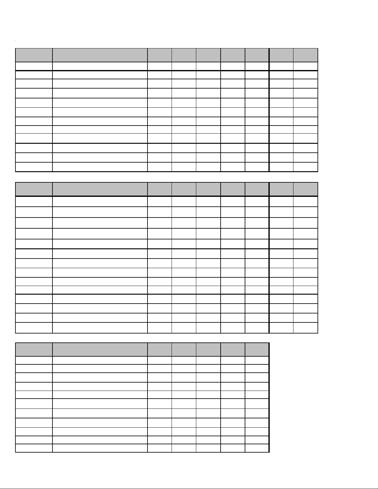
ACCESSORIES
ASZ13
Model Description
ASZ13
018
AFE18-60AAll-Fuel Kit XXXXXXX
ASC01 Anti-Short Cycle Kit XXXXXXX
4
CSR-U-1
CSR-U-2
CSR-U-3
FSK01A
2
Hard-start Kit XXXX
4
Hard-start Kit X X
4
Hard-start Kit XX
Freeze Protection Kit XXXXXXX
LSK02ALiquid Line Solenoid Kit XXXXXX X
OT/EHR18-60Emergency Heat Relay kit XXXXXXX
3
OT18-60A
TX2N4A
4
TX3N4
4
TX5N4
4
Outdoor Thermostat w/Lockout StatXXXXXXX
TXV Kit X X
TXV Kit X X
TXV Kit XXX
GSZ13
Model Description
AFE18-60AAll-Fuel Kit XXXXXXX
G/VSZ13
018
ASZ13
024
G/VSZ13
024
ASZ13
030
G/VSZ13
030
ASZ13
036
G/VSZ13
036
ASZ13
042
G/VSZ13
042
ASZ13
048
G/VSZ13
048
ASZ13
060
G/VSZ13
060
ASC01 Anti-Short Cycle Kit XXXXXXX
CS B-15 Sound Blanket XXX
CS B-16 Sound Blanket X X X X
4
CSR-U-1
CSR-U-2
CSR-U-3
FSK01A
2
Hard-start Kit XXXX
4
Hard-start Kit X X
4
Hard-start Kit XX
Freeze Protection Kit XXXXXXX
LSK02ALiquid Line Solenoid Kit XXXXXX X
OT/EHR18-60Emergency Heat Relay kit XXXXXXX
3
OT18-60A
5
TX2N4A
5
TX3N4
5
TX5N4
GSZ13 Thre e-phase mod els
Model Description
AFE18-60AAll-Fuel Kit XXXXX
ASC01 Anti-Short Cycle Kit XXXXX
2
FSK01A
LSK02ALiquid Line Solenoid Kit XXXXX
OT/EHR18-60Emergency Heat Relay kit XXXXX
OT18-60A
5
TX3N4
5
TX5N4
CSB-15Sound Blanket Kit XXXX
CS B-16 Sound Blanket Kit X
LAKT01Low Ambient Kit XXXXX
Outdoor Thermostat w/Lockout StatXXXXXXX
TXV Kit X X
TXV Kit X X
TXV Kit XXX
1
GSZ13
036*
GSZ13
048*
GSZ13
048*
GSZ13
060*
Freeze Protection Kit XXXXX
3
Outdoor Thermostat w/Lockout StatXXXXX
TXV Kit X X
TXV Kit X X X
GSZ13
060*
Contains 20 brackets; four brackets
needed to anchor unit to pad
2
Installed on indoor coil.
3
Required for heat pump applications
where ambient temperatures fall below
0°F with 50% or higher relative humidity.
4
Condensing units & heat pumps with reciprocating compressors require the use
of start-assist components when used in
conjuntion with an indoor coil using a nonbleed expansion valve refrigerant metering device.
5
Field-installed, non-bleed, expansion
valve kit - Condensing units and heat
pumps with reciprocating compressors
require the use of start-assist components when used in conjuntion with an
indoor coil using a non-bleed thermal expansion valve refrigerant.
42
Page 43

ACCESSORIES
SSZ14
Model Description
SSZ14
018*
AFE18-60AAll-Fuel Kit XXXXXXX X
CSR -U -1 Har d -s t ar t K it X X X X X
CSR -U -2 Har d -s t ar t K it X X X
CSR -U -3 Har d -s t ar t K it XX
FSK01A
1
Freeze Protection Kit XXXXXXX X
LSK02ALiquid Line Solenoid Kit XXXXXXX X
2
OT18-60A
Outdoor Thermostat XXXXXX X X
OT/EHR18-60Emergency Heat Relat Kit XXXXXXX X
TX2N4A³ TXV Kit X X
TX3N4³ TXV Kit X X X
TX5N4³
TXV Kit XX X
ASZ14
Model Description
AFE18-60AAll-Fuel Kit XXXXXXX X
CSR -U -1 Har d -s t ar t K it X X X X X
CSR -U -2 Har d -s t ar t K it X X X
CSR -U -3 Har d -s t ar t K it XX
FSK01A
1
Freeze Protection Kit XXXXXXX X
LSK02ALiquid Line Solenoid Kit XXXXXXX X
2
OT18-60A
Outdoor Thermostat XXXXXX X X
OT/EHR18-60Emergency Heat Relat Kit XXXXXXX X
TX2N4A³ TXV Kit X X
TX3N4³ TXV Kit X X X
TX5N4³
TXV Kit XX X
ASZ14
018*
GSZ14
Model Description
AFE18-60AAll-Fuel Kit XXXXXXX
CSR -U -1 Har d -s t ar t K it X X X X
CSR -U -2 Har d -s t ar t K it X X
CSR -U -3 Har d -s t ar t K it XX
FSK01A
1
Freeze Protection Kit XXXXXXX
LSK02ALiquid Line Solenoid Kit XXXXXXX
2
OT18-60A
Outdoor Thermostat XXXXXX X
OT/EHR18-60Emergency Heat Relat Kit XXXXXXX
TX2N4A³ TXV Kit X X
TX3N4³ TXV Kit X X
TX5N4³
TXV Kit XXX
CSB-15 Sound Blanket Kit X X X
CSB-16 Sound Blanket Kit X X X X
1
Installed on indoor coil
2
Required for heat pump applications where ambient temperatures fall below 0°F with 50% or higher relative humidy.
GSZ14
018*
SSZ14
024*
ASZ14
024*
GSZ14
024*
SSZ14
030*
ASZ14
030*
GSZ14
030*
SSZ14
036*
ASZ14
036*
GSZ14
036*
SSZ14
038*
ASZ14
038*
GSZ14
042*
SSZ14
042*
ASZ14
042*
GSZ14
048*
SSZ14
048*
ASZ14
048*
GSZ14
060*
SSZ14
060*
ASZ14
060*
43
Page 44

ACCESSORIES
AS Z16/DS Z16
Model Description
A/DSZ16
024*
AFE18-60A All-Fue l Kit X X X X X X
CSR -U-1 Har d -st art K it X X X
CSR -U-2 Har d -st art K it X X
CSR -U-3 Har d -st art K it XX
FSK01A
1
Freeze Protection Kit X X X X X X
LSK02A Liqu id Line S o leno id Kit X X X X X X
O T /EHR 18-60 Emerg e n cy He at R e lay Kit X X X X X X
O T 18-60A² Ou t d o or T h e r mo st at w / Locko u t St at X X X X X X
TX 2N 4A TX V K it X
TX3N4 TX V Kit X X
TX5N4 TX V Kit XXX
1
Install ed on indoor coil
2
Required for heat pump applications where ambient temperatures fall below 0°F with 50% or higher relative humidy.
SSZ16
Model Description
AFE18-60A All-Fue l Kit X X X X X X
CSR -U-1 Har d -st art K it X X X
CSR -U-2 Har d -st art K it X X X X
CSR -U-3 Har d -st art K it XX
FSK01A
1
Freeze Protection Kit X X X X X X
LSK02A Liqu id Line S o leno id Kit X X X X X X
O T /EHR 18-60 Emerg e n cy He at R e lay Kit X X X X X X
O T 18-60A² Ou t d o or T h e r mo st at w / Locko u t St at X X X X X X
TX 2N 4A TX V K it X
TX3N4 TX V Kit X X
TX5N4 TX V Kit XXX
1
Install ed on indoor coil
2
Required for heat pump applications where ambient temperatures fall below 0°F with 50% or higher relative humidy.
SSZ16
024*
A/DSZ16
030*
SSZ16
030*
A/DSZ16
036*
SSZ16
036*
A/DSZ16
042*
SSZ16
042*
A/DSZ16
048*
SSZ16
048*
A/DSZ16
060*
SSZ16
060*
44
Page 45
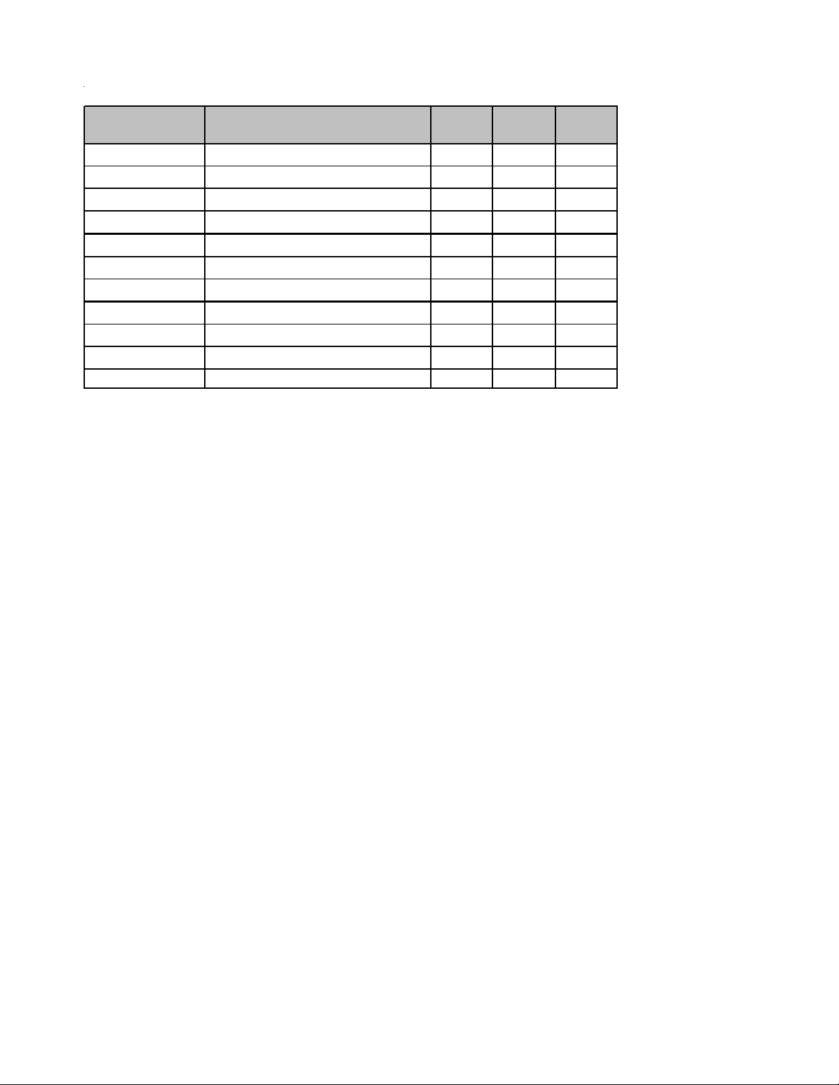
ACCESSORIES
0°F with 50%
refrigerant metering device
ASZ/DSZ18
Model Description
A/DSZ18
036*
AF E18- 6 0A All- Fu el K it X X X
CSR-U-1 Hard-start Kit X
CSR-U-2 Hard-start Kit X
CSR-U-3 Hard-start Kit X X
FSK01A
1
Freeze Protection Kit X X X
LSK02A Liquid Line Solenoid Kit X X X
OT /EHR18-60 Emerge n cy H e at Relay Kit X X X
OT18 -60A² Outd oor Thermostat w/ Lockout Stat X X X
TX2N4A³ TXV Kit
TX3N4³ TXV Kit X
TX5N4³ TXV Kit X X
1 In st alled on indoor coil
Require for heat pump applications where ambient temperatures fall below
2
³ Field-ins tall ed , non-b leed, expansi on valve kit — Condensing un its and he at pumps wit h reciproc ating com pres s ors require the use of
st a rt-assis t components when used in conjunction with an indoor coil using a non-bl eed thermal exp ans ion valve
.
A/DSZ18
048*
or higher relative humidy.
A/DSZ18
060*
45
Page 46
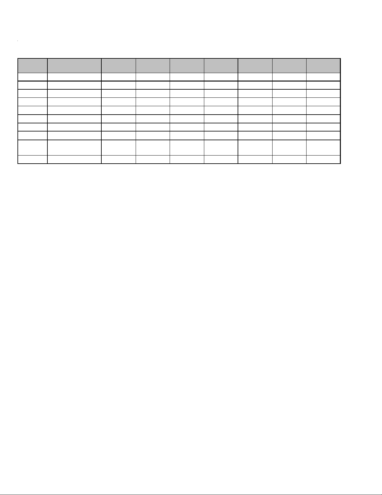
ACCESSORIES
ComfortNet™
ASZC/DSZC 16
ASZC/DSZC 18
Model Description
ABK-20Anchor Bracket KitXXXXXXX
1
TX2N4
TX3N4
TX5N4
TXV Kit X
1
TXV Kit X X
1
TXV Kit X X X X
ASZC16024
DSZC16024
CSR-U-1 Hard-start Kit X X X
CSR-U-2Hard-start Kit XXXX XX
CSR-U-3 Hard-start Kit X X X X
2
FSK01A
OT18-60A
B1141643
Freeze Protect ion Kit X X X X X X X
Ou td oor T h er m os tat /
3
L ockout Th erm ost at
4
24V TransformerXXXXXXX
* Contains 20 brackets; four brackets needed to ancho r unit to pad
1
Field-insta lled, non-bleed, expansion valve kit - Condensing units and heap pumps wit h reciprocating com pressors require the use
XXXXXXX
of sta rt-assist compo nents when used in conjuncti on with an indo or coil using a non-bleed thermal expansion valve ref rigerant
2
Instal led on the indoor coil
3
Available in 24V legacy mode only. This feature is integrated in the communicating mode. Required for heat pump applications
where ambient temperature fall b elow 0 °F with 5 0% or higher relative humidity.
4
Thi s comp one nt is inc lud ed in the CTK0* ** comm un icat ing ther mostat kit.
ASZC16036
DSZC16036
ASZC16048
DSZC16048
ASZC16060
DSZC16060
ASZC18036
DSZC18036
ASZC18048
DSZC18048
ASZC18060
DSZC18060
46
Page 47
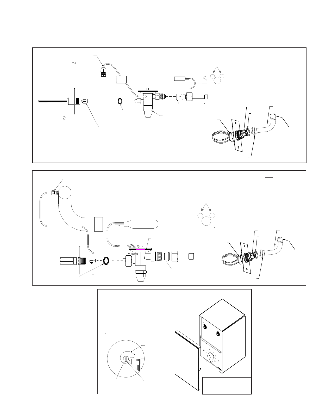
ACCESSORIES
A
EXPANSION VALVE KITS
1/4 FLARE CONNECTION
BULB TO BE LOCATED
AT 10 OR 2 O'CL OCK
For Applications requiring
a field installed access fitting
EVAPORATOR COIL
EVAPORATOR COIL
1/4' FLARE
CONNECTION
SEAL SUPPLIED W/ KIT
REMOVE BEFORE INST A LLING EXPANS ION VALV E
SUCTION LINE
BULB
EXPANSION VALVE
SUCTION LINE
EXPANSION VALVE
BULB
SEAL SUPPLIED W/ KIT
BULB TO BE LOCATED
AT 10 OR 2 O'CLOCK
DISTRIBUTOR
BODY
For Applications not requiring
a field installed access fitting
DISTRIBUTOR
BODY
7/8" NUT
PISTON
SEAL
PISTON
SEAL
TAILPIECE
3/8"SWEAT
TAILPIECE
3/8"SWEAT
SEAL SUPPLIED W/ KIT
7/8" NUT
SEAL SUPPLIED W/ KIT
REMOVE BEFORE
INSTALLING
EXPANSION VALVE
OT/EHR18-60
OUTDOOR THERMOSTAT &
EMERGENCY HEAT RELAY
OT18-60
Thermostat
DEAD
DIAL
45º
Dial
COLD
WARM
Set Point
Indicator
Mark
(Shown @ Oº F)
(Turn Clockwise)
(Turn Coun terclockw ise)
Not for use with
ComfortNet System
47
315º
Set Point
djustment
Screw
Page 48

ACCESSORIES
Y
Wire Nut
FSK01A
FREEZE THERMOSTAT
KIT
Y
k
c
a
l
B
k
c
a
l
B
Wire Nut
Y
Install Line
Thermostat
Here
ASC01A
ANTI-SHORT -CYCLE CONTROL KIT
SHO R T CYCLE
Y1Y2R1
R2
PROTECTOR
Install Line
Thermostat
Here
Wire Nut
B
l
a
c
Y
k
B
l
a
c
Wire Nut
k
Not for use with
ComfortNet System
Y
ELLOW 1
CONTACTOR
BLACK 1
T2 T1
L2
L1
BLACK 1
Y
THERMOSTAT
WIRE
C
UNIT
TERMINAL
BOARD
48
Page 49

ACCESSORIES
COIL ACCESSORIES
COIL MODEL
TX2N4A
TXV KIT
TX3N4
TX V KIT
TX5N4
TXV KIT
FSK01A FREEZE
PROTECTION KIT
CA*F 18246* XX
CA*F 30306* XX
CA*F 31316*
CA*F 36366*
CA*F 36426* XX X
CA*F 37436*
CA*F 48606*
CA*F 49616*
CHPF18246* XX
CHPF24306*
CHPF36366*
X
X
CHPF36426* XX
CHPF37436*
CHPF48606*
CSCF1824N6* XX
CSCF3036N6* XX
CSCF3642N6*
XX X
CSCF4860N6*
HK* SERIES ELETRIC HEA T KITS -
ELECTRIC HEAT KIT APPLICATIONS - MBR, MBE, MBVC
ELEC TRIC HEAT KIT
BLOWER
NO HEAT
MBR0800AA-1AA - XXXXX- -
MBR1200AA-1AA
MBR1600AA-1AA - XXXXXXXXX
MBR2000AA-1AA - XXXXXXXXX
MBE1200AA-1AA
MBE1600AA-1AA -----X----
MBE2000AA-1AA
MBE1200AA-1BA - XXXXX- - - -
MBE1600AA-1BA
MBE2000AA-1AA
MBVC1200AA-1**
MBVC1600AA-1**
MBVC2000AA-1**
-XXXXXXXXX
----XX----
-----X----
-XXXXX- - - -
-XXXXX- - - -
-XXXXXX- - -
-XXXXXX- - -
-XXXXX-X- -
HKR-03*
HKR05-(C)'
HKR-06*
HKR-08(C)*
HKR -10(C)*
HKA-15C*
HKA-20C*
^HKR3-15*
^HKR3-20A
X = Allowable combinations
- = Restricted combinations
^ = Circuit 1: Single Phase for Air Handler Motor
Circuit 2: 3-Phase for HKR3 Heater Kits
49
Page 50

ACCESSORIES
ELECTRIC HEAT KIT APPLICATIONS - ARPF
ARPF 1824
1/16
ARPF 1931
1/16
ARPF3030
1/16
ARPF3642
1/16
ARPF3743
1/16
ARPF 4860
1/16
HKR-03* XXXXXX
HKR-05*, HKR-05C* X X X X X X
HKR-06* XXXXXX
HKR-08*, HKR-08C* X
HKR-10*, HKR-10C* X
HKA-15C* X
1
1
2
HKA-20C* X
^ HKR3-15* X
^ HKR3-20* X
1
X
1
X
2
X
XXXX
1
X
2
X
2
2
2
XXX
3
X
3
X
3
X
3
X
3
X
3
X
3
X
3
X
X
X
X
X
* Revision level that may or may not be designated
C Circ ui t br eak er opt i on
^ Heat ki t required three-phas e power supply
1
Air handler must either be on medium or high speed
2
Air handler must be on high speed
3
For st atic pres sure of 0.6 or higher, air handler m ust be on m edium or high speed.
ELECTRIC HEAT KIT APPLICATIONS - ARUF
ARUF1729
1/16
HKR-03* XXXXXXX
HKR-05*, HKR-05 C* X X X X X X X
HKR-06* XXXXXXX
HKR-08*, HKR-08 C* X
HKR-10*, HKR-10 C* X
HKA-15C* X
1
1
2
HKA-20C* X
^ HKR3-15* X
^ HKR3-20* X
* Revision level that may or may not be designated
C Circuit breaker option
^ Heat kit required three-phase power supply
1
A ir handler must either be on medium or high speed
2
Air handler must be on high speed
3
For static pressure of 0.6 or higher, air handler must be on medium or high speed.
ARUF1824
1/16
1
X
1
X
2
X
ARUF1931
1/16
1
X
1
X
2
X
ARUF3030
1/16
ARUF3642
1/16
ARUF3743
1/16
ARUF4860
1/16
XXXX
1
X
2
X
2
2
2
XXX
3
X
3
X
3
X
3
X
3
X
3
X
3
X
3
X
X
X
X
X
50
Page 51

ACCESSORIES
*
*
*
HKR-03* X X X X
HKR-05*, HKR-05C* X X X X
HKR-06* X X X X
HRK-08*, HKR-08C* X
HKR-10*, HKR-10C*
HKA-15C*
HKA-20C*
^HKR3-15*
^HKR3-20*
*
Revision level that may or may not be designated
C Circuit Breaker option
^ Heat kit requires 3-phase power supply
ELECTRIC HEAT KIT APPLICATIONS - ADPF
ADPF182416 ADPF304216 ADPF486016 ADPF4486016
1
1
X
XX
-X
-X
-X
1
X
1
X
1
X
1
X
2
X
2
X
XX
XX
1
Air handler must be on speed tap 2, 3, 4 or 5
2
Air handler must be on speed tap 4 or 5
3
Air handler must be on speed tap 3, 4 or 5
ELECTRIC HEAT KIT APPLICATIONS - AEPF
X
X
1
X
1
X
AEPF183016 AEPF303616 AEPF313716 AEPF426016
HKR-05* , HKR-05C* X X
HRK-08* , HKR-08C X X X
HKR-10* , HKR-10C
HKA-15C* X
HKA-20C*
*
R evi s io n le ve l that may or may not be designa ted
C Circuit Breaker opti on
1
This heater kit can be used ONLY for 1000 CFM or higher applications
2
This heater kit can be used ONLY for 1200 CFM or higher applications
1
X
XXX
1
1
X
X
2
X
ELECTRIC HEAT KIT APPLICATIONS - AVPTC
MODELS
HKR-03*
HKR-05*/-05C
AVPTC183014A* X X X
AVPTC313714A* X X X
AVPTC426014A* X X X X X X
* Revision level that may or may not be designated.
C Circuit breaker option.
NOTE:
When 8kW and 10kW heat kits are used with an AVPTC1830 and AVPTC3137, matched with 2- ton outdoor unit, see Note 1 below.
1
Set Heater Kit dip switches 9, 10 and 11 to 6kW setting (9-ON, 10-OFF,11-ON) to obtain 840 CFM.
2
This heater kit can only be used for ‘1000 CFM or higher’ applications.
3
This heater kit can only be used for ‘1200 CFM or higher’ applications.
HKR-06*
HKR-08*/-08C
1
X
1X1X2
X
HKR-10*/ -10C
1
X
HKA-15C*
--- --X
X
HKA-20C*
3
51
Page 52

ACCESSORIES
ELECTRIC HEAT KIT APPLICATIONS - ASPF
ASPF183016 ASPF303616 ASPF313716 ASPF426016
HKR-03* X X X X
HKR-05*, HKR-05C* X X X X
HKR-06* X X X X
HRK-08*, HKR-08C* X
HKR-10*, HKR-10C*
+HKR3-15*
+HKR3-20*
HKA-15C*
HKA-20C*
*
Revision l evel that may or may not be designated
C Circu it Breaker option
+ Heat kit requires 3-phase power supply
1
Air handler must be on speed tap 2, 3, 4 or 5
2
Air handler must b e on speed tap 4 or 5
3
Air handler must b e on speed tap 3, 4 or 5
1
1
X
2
X
2
X
1
X
1
X
2
X
2
X
2
X
2
X
1
X
1
X
2
X
2
X
2
X
2
X
X
X
1
X
1
X
1
X
1
X
DRAIN PAN INSULATION KITS - ARUF**14**, ARPT**14**, ASPT**14** & ASUF**14**
MODEL LIS T F OR DOWNF LO W KI TS
DFK-B
Downflo w Ki t
ARUF18B14** AR UF30C14** ARUF48D14**
ARUF24B14** AR UF36C14** ARUF60D14**
ARUF30B14** AR UF42C14** ARPT36D 14**
ARPT18B14** ARPT36C14** ARPT4 2D14**
ARPT24B14** ASPT36C14** ARPT48D14**
ARPT30B14** ASPT42C14** ARPT60D14**
ASPT24B14** ASPT48C14 ** ASPT48D14**
52
DFK-C
Downflo w Ki t
ASU F49C14** ASPT60D 14**
DFK-D
Downflo w Ki t
ASUF59D14**
Page 53

ACCESSORIES
ARPT**14**
Heat Ki t A p pl i cat i o ns
Type / model 18B14-A* 24B14-A* 30B14-A* 36C14-A* 36D14-A* 42D14-A* 48D14-A* 60D14-A*
HKSX03XC* XXXXXXXX
HKSX05XC* XXXXXXXX
HKSX06XC* XXXXXXXX
HKSX08XC* XXXXXXXX
HKSX10XC* XXXXXXXX
HKSX15XF* XXXXX
HKSX20XF* XXXXX
HKSC05XC* XXXXXXXX
HKSC08XC* XXXXXXXX
HKSC10XC* XXXXXXXX
HKSC15XA* XXXXXX
HKSC15XB* XXXXXX
HKSC15XF* XXXXX
HKSC19CA* X
HKSC19CB* X
HKSC20DA* XXXX
HKSC20DB* XXXX
HKSC20XF* XXXXX
ARPT
53
Page 54

ACCESSORIES
ARUF**14**
Heat Ki t Ap p l ication s
Type / model 18B14-A * 24B14-B* 24B14-C* 30B14-A* 30C14-B* 36C14-B* 42C14-A* 48D14-A* 60D14-A*
HKSX03XC* XXXXXXXXX
HKSX05XC* XXXXXXXXX
HKSX06XC* XXXXXXXXX
HKSX08XC* XXXXXXXXX
HKSX10XC* XXXXXXXXX
HKSX15XF* XXXXX
HKSX20XF* XXXXX
HKSC05XC* XXXXXXXXX
HKSC08XC* XXXXXXXXX
HKSC10XC* XXXXXXXXX
HKSC15XA* XXXXXX
HKSC15XB* XXXXXX
ARUF
HKSC15XF* XXXXX
HKSC19CA* X X X
HKSC19CB* X X X
HKSC20DA* XX
HKSC20DB* XX
HKSC20XF* XXXXX
HKSC25DC* XXX
* Revision level that may or may not be designated
Refer to the minimum airflow requirements for each of the heat kits.
54
*ARUF
ARPT
18 715 715 715 715 950
24 715 715 715 715 950
30B 715 715 715 715 875 875
30C 1170 1170 1170 1170 1345 1345
36 1170 1170 1170 1170 1345 1345
42 1170 1170 1170 1170 1345 1345
48 1590 1590 1590 1590 1715 1715 1715
60 1590 1590 1590 1590 1715 1715 1715
Minimum CFM req uired for Heat er Kit s
3 5 6 8 1015192025
HEATER (k W)
Page 55

ACCESSORIES
ASUF**14**
Heat Kit A pp licati o ns
ASUF
Type / model 29B14-A* 39C14-A* 49C14-A* 59D14-A*
HKSX03XC* X X X X
HKSX05XC* X X X X
HKSX06XC* X X X X
HKSX08XC* X X X X
HKSX10XC* X X X X
HKSX15XF* X X X
HKSX20XF* X X X
HKSC05XC* X X X X
HKSC08XC* X X X X
HKSC10XC* X X X X
HKSC15XA* X X X
HKSC15XB* X X X
HKSC15XF* X X X
HKSC19CA* X X
HKSC19CB* X X
HKSC20DA* X
HKSC20DB* X
HKSC20XF* X X X
HKSC25DC* X
* Revision level that may or may not be designated.
Refer to the minimum airflow requirements for each of the heat kits.
ASUF
29 715 715 715 715 875
39 11 70 1170 1170 1170 1345 1345
49 11 70 1170 1170 1170 1345 1345
59 15 90 1590 1590 1590 1715 1715 1715
Minimum C F M requi red fo r Heater Kits
3 5 6 8 10 15 19 20 25
HEATE R (kW)
55
Page 56

ACCESSORIES
4
4
4
4
4
ASPT**14**
Heat Kit A p pli cat i o n s
Type / mode l 24B14-A* 30C14-A* 36C14-A* 42C14-A* 48C14-A* 42D 14-A* 48D14-A* 60D14-A*
HKSX03XC* XXXXXXXX
HKSX05XC* XXXXXXXX
HKSX06XC* XXXXXXXX
HKSX08XC* XXXXXXXX
HKSX10XC* XXXXXXXX
HKSX15XF* X X X X X X
HKSX20XF* X X X X X X
HKSC05XC* XXXXXXXX
HKSC08XC* XXXXXXXX
HKSC10XC* XXXXXXXX
HKSC15XA* X X X X X X
HKSC15XB* X X X X X X
HKSC15XF* X X X X X X
HKSC19CA* X X X
HKSC19CB* X X X
HKSC20DA* XXX
HKSC20DB* XXX
HKSC20XF* X X X X X X
HKSC25DC* XX
* Revision level that may or may not be designated.
Refer to the minimum airflow requirements for each of the heat kits.
ASP T
Heater (KW)
3 5 6 8 10 15 19 20 25
ASPT24B1
ASPT30C1
ASPT36C1
ASPT42C1
ASPT48C1
715 715 715 715 875 NR NR NR NR
730 715 715 715 950 NR NR NR NR
NR 1170 1170 1170 1170 1345 1345 1345 NR
NR 1170 1170 1170 1170 1345 1345 1345 NR
NR 1170 1170 1170 1170 1345 1345 1345 NR
ASPT42D1 N R 1590 1590 1590 1590 1715 NR 1715 NR
ASPT48D1 N R 1590 1590 1590 1590 1715 NR 1715 1715
ASPT60D1 N R 1590 1590 1590 1590 1715 NR 1715 1715
MIN IMUM CFM REQUIRED FOR HEATER KITS
56
Page 57

ACCESSORIES
p
p
p
p
p
AVPTC**14**
Heat Kit Applications
Type / M o del 24B14-A* 30C14-A* 36C14-A* 48C 14-A* 42D 14-A*
AVP TC
†
48D14-A*
††
60D14-A*
HKS X03XC X X X
HKSX05XC XXXXXXX
HKSX06XC XXXXXXX
HKSX08XC XXXXXXX
HKSX10XC XXXXXXX
HKSX15XF* XXXXX
HKSX20XF* XXXXX
HKSC05XC XXXXXXX
HKSC08XC XXXXXXX
HKSC10XC XXXXXXX
HKSC 15XA X X X X X
HKSC 15XB X X X X X
HKSC15XF* XXXXX
HKSC19CA* X X
HKSC19CB* X X
HKSC20DA XXX
HKSC 20DB XXX
HKSCX20XF* XXXXX
HKSC25DC* XX
* Revisio n level that may or may no t be design at ed.
Refer to the minimum airflo w requirements for each of the heat kits.
†††
†Fo r ma tch u p with a 2 ton outd oor un it: He ater kit ap pli caƟon shall not exceed 10 kW.
Ai rfl ow fo r 5 kW u
††For match u
Ai rfl ow fo r 5 kW u
†††For match u
Airfl ow for 5 kW u
** 3 kW heater kit is not applicable for this indoor application.
to 10 k W hea ter ki ts s ha ll be se t to 850 cfm speed tap of ON-ON-ON.
wi th a 3 ton outd oor un it: He a ter kit applicaƟ on shall not exceed 15 kW.
to 15 k W hea ter ki ts s ha ll be se t to 1400 cfm speed tap of ON-ON-OFF.
wi th a 3.5 ton outdoo r un it: Hea ter kit applicaƟon shall not exceed 20 kW.
to 20 kW h ea ter ki ts s ha ll be se t to 1620 cfm speed tap of ON-ON-OFF
Heater kit (Kw)
3 5 6 8 10 15 19 20 21 or 25
AVPTC24B14 550 650 700 800 850 NR NR NR NR
AVPTC30C14 600 700 750 875 950 NR NR NR NR
AVPTC36C14 NR 850 900 1000 1200 1440 1500 1500 NR
AVPTC48C14 NR 850 900 1000 1200 1440 1500 1500 NR
AVPTC42D14
AVPTC48D14
AVPTC60D14
†
††
†††
850** 1250 1300 1500 1550 1720 NR 1800 NR
NR 1250 1300 1500 1550 1720 NR 1815 1850
NR 1250 1300 1500 1550 1780 NR 1850 1850
MINIMUM CFM REQU IRED FOR HEATER KI TS, Se e note s be low
Note: Airflow data shown applies to the electric heat only in either legacy mode or communi cating mode operation
NR - Not rated
* Within thermostat user menu CTK0* communicating thermostat will display 20KW for OFF- OFF- ON dip switch selection,
21kW fo r
†For match up with a 2 ton outdoor unit: Heater kit applicaƟon shall not exceed 10 kW.
Airflow for 5 kW up to 10 kW heater kits shall be set to 850 cfm speed tap of ON-ON-ON.
††For match up with a 3 ton outdoor unit: Heater kit applicaƟon shall not exceed 15 kW.
Ai rflow for 5 kW up to 15 kW he a ter kits sha ll be s et to 1300 cfm s pe e d tap of ON-OFF-ON.
†††For match up with a 3.5 ton outdoor unit: Heater kit applicaƟon shall not exceed 20 kW.
Airfl ow for 5 kW up to 20 kW h eater kits s hall be se t to 1500 cfm spe ed ta p of ON-OFF-OFF
57
Page 58

PRODUCT DESIGN
This section gives a basic description of cooling unit operation, its various components and their basic operation.
Ensure your system is properly sized for heat gain and loss
according to methods of the Air Conditioning Contractors
Association (ACCA) or equivalent.
CONDENSING UNIT
The condenser air is pulled through the condenser coil by a
direct drive propeller fan. This condenser air is then discharged out of the top of the cabinet. These units are
designed for free air discharge, so no additional resistance,
like duct work, shall be attached.
The suction and liquid line connections on present models
are of the sweat type for field piping with refrigerant type
copper. Front seating valves are factory installed to accept
the field run copper. The total refrigerant charge for a normal
installation is factory installed in the condensing unit.
GSX, GSZ, ASX, ASZ, SSX, SSZ, DSX, DSZ, VSX, and VSZ
models are available in 1 1/2 through 5 ton sizes and use R410A refrigerant. They are designed for 208/230 volt single
phase applications.
GSX/GSZ *****2 models are available in 2 and 3 ton sizes and
use R-410A refrigerant. They are designed for 220/240 volt
single phase applications.
GSX/GSZ *****3 models are available in 3, 4, and 5 ton sizes
and use R-410A refrigerant. They are designed for 208/230
volt 3-phase applications.
GSX/GSZ *****4 models are available in 3, 4, and 5 ton sizes
and use R-410A refrigerant. They are designed for 380/420
volt 3-phase applications.
GSX/GSZ *****5 models are available in 3, 4, and 5 ton sizes
and use R-410A refrigerant. They are designed for 380/420
volt 3-phase applications.
ASX, ASZ, DSX and DSZ R-410A model units use the
Copeland Scroll "Ultratech" Series compressors which are
specifically designed for R-410A refrigerant. These units also
have Copeland
GSX, GSZ, SSX, SSZ, VSX, and VSZ R-410A model units,
except for GSX130181C*, VSX130181B*, VSX130241E*,
VSX130421B*, and VSX130481B*, use the Copeland Scroll
"Ultratech" Series compressors which are specifically designed for R-410A refrigerant.
ASXC, ASZC, DSXC, DSZC models are available in 2
through 5 ton sizes and use R-410A refrigerant. They are
designed for 208/230 volt single phase applications.
ASXC, ASZC, DSXC, DSZC R-410A model units use the
Copeland Scroll "Ultratech" Series compressors which are
specifically designed for R-410A refrigerant. These units also
have Copeland® ComfortAlert diagnostics. The Copeland
ComfortAlert diagnostics are integrated into the unitary (UC)
control. These models are ComfortNetTM ready.
There are a number of design characteristics which are
different from the traditional reciprocating and/or scroll compressors.
®
ComfortAlert diagnostics.
"Ultractech" Series scroll compressors will not have a discharge thermostat. Some of the early model scroll compressors required discharge thermostat.
"Ultratech" Series scroll compressors use "POE" or
polyolester oil which is NOT compatible with mineral oil
based lubricants like 3GS. "POE" oil must be used if
additional oil is required.
COILS AND BLOWER COILS - LEGACY
MODELS
MBR/MBE/MBVC blower cabinets are designed to be used
as a two-piece blower and coil combination. MBR/MBE/
MBVC blower sections can be attached to cased evaporator
coil. This two-piece arrangement allows for a variety of mixmatching possibilities providing greater flexibility. The MBE/
MBVC blower cabinets use a variable speed motor that
maintains a constant airflow with a higher duct static.
MBE/MBVC blower cabinests are approved for applications
with cooling coils of up to 0.8 inches W.C. external static
pressure. The MBE models includes a feature that allows
airflow to be changed by +10% or -15%. The MBVC models
allow airflow trimming of +/-10%.
The MBR blower cabinet uses a PSC motor. It is approved for
applications with cooling coils of up to 0.5 inches W.C.
external static pressure.
The MBR/MBE/MBVC blower cabinets with proper coil
matches can be positioned for upflow, counterflow, horizontal
right or horizontal left operation. All units are constructed with
R-4.2 insulation. In areas of extreme humidity (greater than
80% consistently), insulate the exterior of the blower with
insulation having a vapor barrier equivalent to ductwork
insulation, providing local codes permit.
The CAUF, CAPF and CAPT coils are designed for upflow and
counterflow applications. The CACF and CHPF coils are
designed for horizontal applications.
Communicating Unitary Control (UC) PCB
The Communicating System Unitary Control PCB is a microprocessor-based control for heat pump and air conditioning
condensing units with single-phase compressors up to 5 ton
capacity operating on standard residential or Delta and Wye
commercial power. The control incorporates the basic functionality of existing defrost controls, outdoor thermostats,
contactors, compressor staging controls, short cycle controls, line voltage monitors, Comfort Alert™ or CoreSense
Module (dependent upon which module you are using), two
speed condenser fan relays and the Active Protection component of enabled thermostats. The control is designed to
work as part of a fully communicating HVAC system with 4
®
wires. The control also supports legacy 24VAC thermostat
inputs for Y1, Y2, O and 24VAC outputs for RVS, W1, and L
for non-communicating systems. Outputs include compressor power, compressor stage select, and outdoor fan high
and outdoor fan low speed. System inputs include high/low
pressure switches, as well as thermistor inputs for outdoor
coil temperature and outdoor air temperature.
58
Page 59

PRODUCT DESIGN
The ASX & ASXC [16 & 18], ASZ & ASZC [16 & 18], DSX &
DSXC [16 & 18] and DSZ & DSZC [16 & 18] series split
system units use a two-stage scroll compressor. The twostep modulator has an internal unloading mechanism that
opens a bypass port in the first compression pocket, effectively reducing the displacement of the scroll. The opening
and closing of the bypass port is controlled by an internal
electrically operated solenoid.
The ZPS/ZRS two-step modulated scroll uses a single step
of unloading to go from full capacity to approximately 67%
capacity. A single speed, high efficiency motor continues to
run while the scroll modulates between the two capacity
steps.
FIGURE A
A scroll is an involute spiral which, when matched with a
mating scroll form as shown, generates a series of crescent
shaped gas pockets between the two members.
During compression, one scroll remains stationary (fixed
scroll) while the other form (orbiting scroll) is allowed to orbit
(but not rotate) around the first form.
As this motion occurs, the pockets between the two forms
are slowly pushed to the center of the two scrolls while
simultaneously being reduced in volume. When the pocket
reaches the center of the scroll form, the gas, which is now
at a high pressure, is discharged out of a port located at the
center.
During compression, several pockets are being compressed
simultaneously, resulting in a very smooth process. Both the
suction process (outer portion of the scroll members) and the
discharge process (inner portion) are continuous.
Some design characteristics of the Compliant Scroll compressor are:
• Compliant Scroll compressors are more tolerant of liquid
refrigerant.
NOTE: Even though the compressor section of a Scroll
compressor is more tolerant of liquid refrigerant, continued floodback or flooded start conditions may wash oil
from the bearing surfaces causing premature bearing
failure.
• "Ultratech" Series scroll compressors use "POE" or
polyolester oil which is NOT compatible with mineral oil
based lubricants like 3GS. "POE" oil must be used if
additional oil is required.
• Compliant scroll compressors perform "quiet" shutdowns
that allow the compressor to restart immediately without
the need for a time delay. This compressor will restart
even if the system has not equalized.
NOTE: Operating pressures and amp draws may differ
from standard reciprocating compressors. This information can be found in the unit's Technical Information
Manual.
59
Page 60
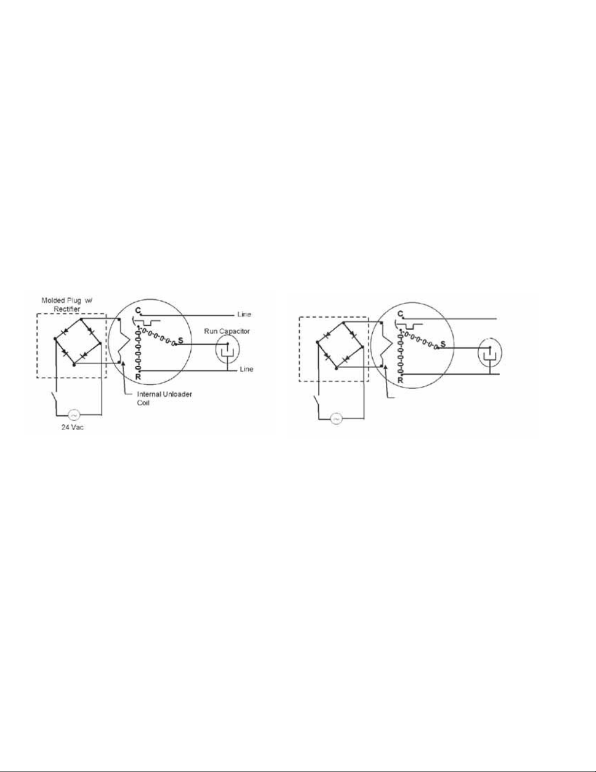
PRODUCT DESIGN
CAPACITY CONTROL - LEGACY MODELS
During the compression process, there are several pockets
within the scroll that are compressing gas. Modulation is
achieved by venting a portion of the gas in the first suction
pocket back to the low side of the compressor thereby
reducing the effective displacement of the compressor. See
Figure A. Full capacity is achieved by blocking these vents,
increasing the displacement to 100%. A solenoid in the
compressor, controlled by an external 24-volt ac signal,
moves the slider ring that covers and uncovers these vents.
The vent covers are arranged in such a manner that the
compressor operates somewhere around 67% capacity when
the solenoid is not energized and 100% capacity when the
solenoid is energized. The loading and unloading of the two
step scroll is done “on the fly” without shutting off the motor
between steps. See Figure B below. The unloaded mode
default was chosen for two reasons:
CAPACITY CONTROL - COMFORTNET
TM
MODELS
During the compression process, there are several pockets
within the scroll that are compressing gas. Modulation is
achieved by venting a portion of the gas in the first suction
pocket back to the low side of the compressor thereby
reducing the effective displacement of the compressor. See
Figure A. Full capacity is achieved by blocking these vents,
increasing the displacement to 100%. A solenoid in the
compressor, controlled by an external 24-volt ac signal,
moves the slider ring that covers and uncovers these vents.
The vent covers are arranged in such a manner that the
compressor operates somewhere around 67% capacity when
the solenoid is not energized and 100% capacity when the
solenoid is energized. The loading and unloading of the two
step scroll is done “on the fly” without shutting off the motor
between steps. See Figure C below. The unloaded mode
default was chosen for two reasons:
Molded Plug*
Line
Run Capacitor
FIGURE B
1. It is expected that the majority of run hours will be in the
low capacity, unloaded mode.
2. It allows a simple two-stage thermostat to control capacity through the second stage in both cooling and possibly
heating if desired.
UNLOADER SOLENOID
A nominal 24-volt direct current coil activates the internal
unloader solenoid. The input control circuit voltage must be
18 to 28 volt ac. The coil power requirement is 20 VA. The
external electrical connection is made with a molded plug
assembly. This plug is connected to the Comfort Alert™ or
CoreSense™ Module (dependent upon which module you are
using) which contains a full wave rectifier to supply direct
current to the unloader coil.
Line
Internal Unloader
Coil
24 VAC
*Rectifier is i n teg rated on the UC PCB
FIGURE C
1. It is expected that the majority of run hours will be in the
low capacity, unloaded mode.
2. It allows a simple two-stage thermostat to control capacity through the second stage in both cooling and possibly
heating if desired.
UNLOADER SOLENOID
A nominal 24-volt direct current coil activates the internal
unloader solenoid. The input control circuit voltage must be
18 to 28 volt ac. The coil power requirement is 20 VA. The
external electrical connection is made with a molded plug
assembly. This plug is connected to the Communicating
Unitary Control PCB (UC PCB) which contains a full wave
rectifier to supply direct current to the unloader coil.
60
Page 61

SYSTEM OPERA TION
COOLING
The refrigerant used in the system is R-410A. It is a clear,
colorless, non-toxic and non-irritating liquid. R-410A is a
50:50 blend of R-32 and R-125. The boiling point at atmospheric pressure is -62.9°F.
A few of the important principles that make the refrigeration
cycle possible are: heat always flows from a warmer to a
cooler body. Under lower pressure, a refrigerant will absorb
heat and vaporize at a low temperature. The vapors may be
drawn off and condensed at a higher pressure and temperature to be used again.
The indoor evaporator coil functions to cool and dehumidify
the air conditioned spaces through the evaporative process
taking place within the coil tubes.
NOTE: The pressures and temperatures shown in the
refrigerant cycle illustrations on the following pages are for
demonstration purposes only. Actual temperatures and pressures are to be obtained from the "Expanded Performance
Chart".
Liquid refrigerant at condensing pressure and temperatures,
(270 psig and 122°F), leaves the outdoor condensing coil
through the drier and is metered into the indoor coil through
the metering device. As the cool, low pressure, saturated
refrigerant enters the tubes of the indoor coil, a portion of the
liquid immediately vaporizes. It continues to soak up heat and
vaporizes as it proceeds through the coil, cooling the indoor
coil down to about 48°F.
Heat is continually being transferred to the cool fins and tubes
of the indoor evaporator coil by the warm system air. This
warming process causes the refrigerant to boil. The heat
removed from the air is carried off by the vapor.
As the vapor passes through the last tubes of the coil, it
becomes superheated. That is, it absorbs more heat than is
necessary to vaporize it. This is assurance that only dry gas
will reach the compressor. Liquid reaching the compressor
can weaken or break compressor valves.
The compressor increases the pressure of the gas, thus
adding more heat, and discharges hot, high pressure superheated gas into the outdoor condenser coil.
In the condenser coil, the hot refrigerant gas, being warmer
than the outdoor air, first loses its superheat by heat transferred from the gas through the tubes and fins of the coil. The
refrigerant now becomes saturated, part liquid, part vapor and
then continues to give up heat until it condenses to a liquid
alone. Once the vapor is fully liquefied, it continues to give up
heat which subcools the liquid, and it is ready to repeat the
cycle.
HEATING
The heating portion of the refrigeration cycle is similar to the
cooling cycle. By energizing the reversing valve solenoid coil,
the flow of the refrigerant is reversed. The indoor coil now
becomes the condenser coil, and the outdoor coil becomes
the evaporator coil.
The check valve at the indoor coil will open by the flow of
refrigerant letting the now condensed liquid refrigerant bypass the indoor expansion device. The check valve at the
outdoor coil will be forced closed by the refrigerant flow,
thereby utilizing the outdoor expansion device.
The restrictor orifice used with the CA*F, CHPF and CH**FCB
coils will be forced onto a seat when running in the cooling
cycle, only allowing liquid refrigerant to pass through the
orifice opening. In the heating cycle, it will be forced off the
seat allowing liquid to flow around the restrictor. A check valve
is not required in this circuit.
COOLING CYCLE
For legacy room thermostat: When the room thermostat calls
for cool, the contacts of the room thermostat close making
terminals R to Y1 & G (if thermostat calls for low stage cool),
or R to Y1, Y2 & G (if thermostat calls for high stage cool),
the low voltage circuit of the transformer is completed.
Current now flows through the magnetic holding coils of the
compressor contactor (CC) and fan relay (RFC). If thermostat
calls for high stage cool, the microprocessor on the UC board
will also energize the compressor high stage solenoid to run
the compressor at full capacity.
This draws in the normally open contact CC, starting the
compressor and condenser fan motors in either low or high
stage depending on the thermostat’s demand. At the same
time, contacts RFC close, starting the indoor fan motor.
When the thermostat is satisfied, it opens its contacts,
breaking the low voltage circuit, causing the compressor
contactor and indoor fan relay to open, shutting down the
system.
If the room thermostat fan selector switch should be set on
the “on” position, then the indoor blower would run continuously rather than cycling with the compressor.
GSZ, ASZ, SSZ, DSZ, and VSZ models energize the reversing valve thorough the "O" circuit in the room thermostat.
Therefore, the reversing valve remains energized as long as
the thermostat subbase is in the cooling position. The only
exception to this is during defrost.
For heat pumps, during cooling cycle the reversing valve is
energized as the room thermostat closes “O” terminal to R
and the microprocessor on the UC board responds to such a
condition by energizing the solenoid coil on the reversing
valve.
For communicating room thermostat: When the room thermostat calls for either low stage cool or high stage cool,
appropriate commands are sent via the data 1 and data 2 lines
to the outdoor unit's UC control. The UC control energizes the
on-board compressor relay and the on-board outdoor fan
relay. The compressor high stage solenoid is energized if it
is a high stage call.
The UC control sends a fan command to the indoor unit (air
handler or furnace). The indoor unit operates the indoor
blower at the appropriate airflow level. The system operates
at the cooling level demanded by the thermostat.
61
Page 62

SYSTEM OPERATION
When the thermostat is satisfied, appropriate commands are
sent to the UC control. The compressor relay and outdoor
fan relay is de-energized. The compressor high stage
solenoid is de-energized if it was energized. The UC control
sends an appropriate command to the indoor unit to deenergize the indoor blower motor.
If room thermostat fan status is set to be “on”, then indoor
blower would run continuously rather than cycling with the
compressor.
For heat pumps, the reversing valve is energized during a
cooling a cycle. The call for cooling from the communicating
thermostat indicates to the control that the reversing valve is
to be energized during cooling operation.
DEFROST CYCLE - LEGACY MODELS
The defrosting of the outdoor coil is jointly controlled by the
defrost control board and the defrost thermostat.
Solid State Defrost Control
During operation the power to the circuit board is controlled
by a temperature sensor, which is clamped to a return bend
(3/8" coils) or a feeder tube (5 mm coils) entering the outdoor
coil. Defrost timing periods of 30, 60, or 90 minutes may be
selected by connecting the circuit board jumper to 30, 60, or
90 respectively. Accumulation of time for the timing period
selected starts when the sensor closes (approximately 31°
F), and when the room thermostat calls for heat. At the end
of the timing period, the unit’s defrost cycle will be initiated
provided the sensor remains closed. When the sensor opens
(approximately 75° F), the defrost cycle is terminated and the
timing period is reset. If the defrost cycle is not terminated
due to the sensor temperature, a ten minute override interrupts the unit’s defrost period. The new upgraded defrost
control has a 12 minute override interrupt.
DEFROST CYCLE - COMFORTNETTM MODELS
The defrosting of the outdoor coil is jointly controlled by the
UC PCB and the outdoor coil temperature (OCT) sensor.
The OCT sensor is clamped to a feeder tube entering the
outdoor coil. Defrost timing periods of 30, 60, 90 or 120
minutes may be selected via the dipswitch settings on the UC
PCB. In a communicating system, the defrost timing periods
can also be selected in the communicating thermostat user
menu. During operation the microprocessor on the UC checks
coil temperature via the OCT sensor every 30, 60, 90, or 120
minutes when there is a call for heating. If by the time the
microprocessor checks the coil temperature, and it's low
enough (approximately 31°F), and if there is a call for heat
from the thermostat, the PCB will initiate a defrost. When the
microprocessor detects the coil temperature to be high
enough (approximately 75 0F), or 10 minutes of maximum
defrost cycle time has elapsed, whichever occurs first, the
defrost cycle is terminated and the timing period is reset. The
field service personnel can also advance a heat pump to the
defrost cycle by simultaneously pressing the “TEST” button
and the “RECALL” button on the UC board.
62
HEATING CYCLE
The reversing valve on the GSZ, SSZ, ASZ and DSZ models
is energized in the cooling cycle through the "O" terminal on
the room thermostat.
These models have a 24 volt reversing valve coil. When the
thermostat selector switch is set in the cooling position, the
"O" terminal on the thermostat is energized all the time.
Care must be taken when selecting a room thermostat. Refer
to the installation instructions shipped with the product for
approved thermostats.
HEATING CYCLE
For legacy room thermostat: When the room thermostat
calls for heat, the contacts of the room thermostat close
making terminals R to Y & G, the low voltage circuit of the
transformer is completed. Current now flows through the
magnetic holding coils of the compressor contactor (CC) and
fan relay (RFC).
This draws in the normally open contact CC, starting the
compressor condenser fan motors. At the same time,
contacts RFC close, starting the indoor fan motor.
When the thermostat is satisfied, it opens its contacts,
breaking the low voltage circuit, causing the compressor
contactor and indoor fan relay to open, shutting down the
system.
If the room thermostat fan selector switch should be set to
the “on” position, then the indoor blower would run continuously rather than cycling with the compressor.
For communicating room thermostat: When the room thermostat calls for either low stage heat or high stage heat,
appropriate commands are sent via the data 1 and data 2
lines to the outdoor unit's UC control. The UC control
energizes the on-board compressor relay and the on-board
outdoor fan relay. The compressor high stage solenoid is
energized if it is a high stage call. The UC control sends a
fan command to the indoor unit (air handler or furnace). The
indoor unit operates the indoor blower at the appropriate
airflow level. The system operates at the cooling level
demanded by the thermostat.
Page 63
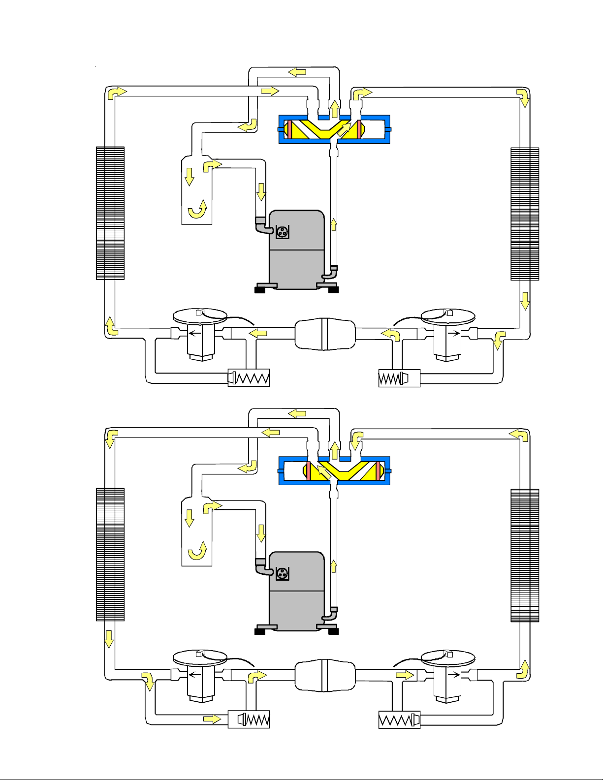
SYSTEM OPERA TION
COOLING CYCLE
Reversing Valve
(Energized)
Indoor
Coil
HEATING CYCLE
Outdoor
Coil
Accumulator
Thermostatic
Expansion
Valve
Bi-Flow
Filter Dryer
Check Valve
Indoor
Coil
Reversing Valve
(De-Energized)
Outdoor
Coil
Accumulator
Thermostatic
Expansion
Valve
Bi-Flow
Filter Dryer
Check Valve
63
Page 64

SYSTEM OPERATION
EXPANSION VALVE/CHECK VALVE ASSEMBLY
IN COOLING OPERATION
Most expansion valves used in current Amana
use an internally checked expansion valve.
This type of expansion valve does not require an external check valve as shown above.
However, the principle of operation is the same.
RESTRICTOR ORIFICE ASSEMBLY
IN COOLING OPERATION
EXPANSION VALVE/CHECK VALVE ASSEMBLY
IN HEATING OPERATION
®
Brand Heat Pump products
RESTRICTOR ORIFICE ASSEMBLY
IN HEATING OPERATION
In the cooling mode, the orifice is pushed into its
seat, forcing refrigerant to flow through the metered
hole in the center of the orifice.
64
In the heating mode, the orifice moves back off its
seat, allowing refrigerant to flow unmetered around
the outside of the orifice.
Page 65
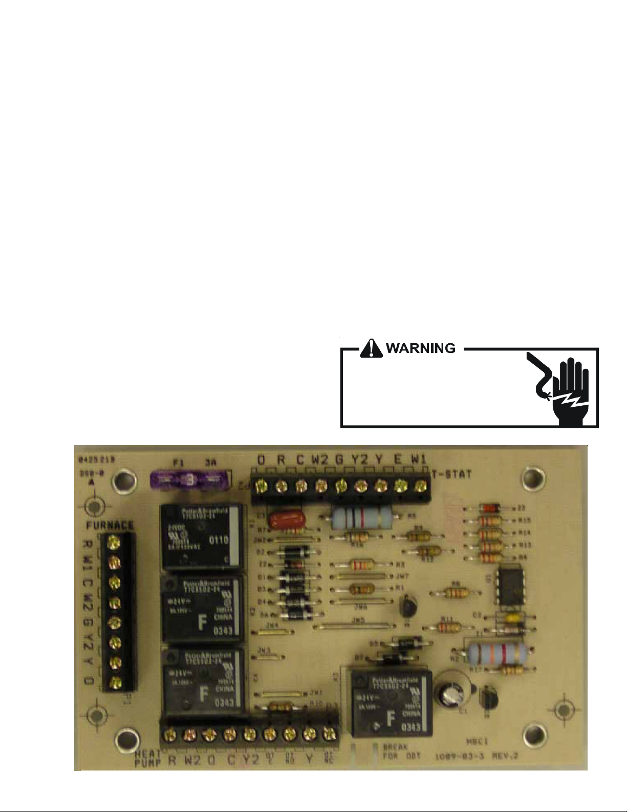
SYSTEM OPERA TION
When the thermostat is satisfied, appropriate commands are
sent to the UC control. The compressor relay and outdoor
fan relay is de-energized. The compressor high stage
solenoid is de-energized if it was energized. The UC control
sends an appropriate command to the indoor unit to deenergize the indoor blower motor.
AFE18-60A CONTROL BOARD
DESCRIPTION
The AFE18 control is designed for use in heat pump applications where the indoor coil is located above/downstream of a
gas or fossil fuel furnace. It will operate with single and two
stage heat pumps and single and two stage furnaces. The
AFE18 control will turn the heat pump unit off when the
furnace is turned on. An anti-short cycle feature is also
incorporated which initiates a 3 minute timed off delay when
the compressor goes off. On initial power up or loss and
restoration of power, this 3 minute timed off delay will be
initiated. The compressor won’t be allowed to restart until the
3 minute off delay has expired. Also included is a 5 second
de-bounce feature on the “Y, E, W1 and O” thermostat inputs.
These thermostat inputs must be present for 5 seconds
before the AFE18 control will respond to it.
An optional outdoor thermostat, OT18-60A, can be used with
the AFE18 to switch from heat pump operation to furnace
operation below a specific ambient temperature setting, i.e.
break even temperature during heating. When used in this
manner, the “Y” heat demand is switched to the “W1” input
to the furnace by the outdoor thermostat and the furnace is
used to satisfy the first stage “Y” heat demand. On some
controls, if the outdoor thermostat fails closed in this position
during the heating season, it will turn on the furnace during
the cooling season on a “Y” cooling demand. In this
situation, the furnace produces heat and increases the
indoor temperature thereby never satisfying the cooling
demand. The furnace will continue to operate and can only
be stopped by switching the thermostat to the off position or
removing power to the unit and then replacing the outdoor
thermostat. When the AFE18 receives a “Y” and “O”
input from the indoor thermostat, it recognizes this as a
cooling demand in the cooling mode. If the outdoor thermostat is stuck in the closed position switching the “Y” demand
to the “W1” furnace input during the cooling mode as
described above, the AFE18 won’t allow the furnace to
operate. The outdoor thermostat will have to be replaced to
restore the unit to normal operation.
HIGH VOLTAGE!
Disconnect ALL power before servicing
or installing. Multiple power sources
may be pres e nt. Fail ure to do so m ay
cause property da m a ge, personal injury
or death.
65
Page 66

TROUBLESHOOTING CHART
COOLING/HP ANALYSIS CHART
Com plaint
PO SS I BL E CAUSE
DOTS IN ANALYS I S
GUIDE I NDICAT E
"PO S SI BL E CAUSE"
Pow er Failure
Blown Fuse
Unbalan ced Pow er, 3PH
Loose Connection
Shorted or Broken Wires
Open Fan Overload
Faulty Thermos tat
Faulty Transformer
Shorted o r O pe n Capa citor
Internal Compressor Overload Open
Shorted or Grounded Compressor
Compressor Stuc k
Faulty Compres s or Contactor
Faulty Fan Relay
Open Contr ol Circuit
Low Voltage
Faulty Evap. Fan Motor
Shorted or Grounded Fan Motor
Improper Cooling Anticipator
Shor t a ge of Refriger a n t
Restricted Liquid Line
Open Element or Limit on Elec. Heater
Dirty Air Filter
Dirty Indoor Coil
Not enough air ac ross Indoor Coil
Too much air across Indoor Coil
Overc harge of Refrigerant
Dirty Outdoor Coil
Noncondensibles
Recirculation of Condensing Air
Infiltration of Outdoor Air
Improperly Located Thermostat
Air Flow Unbalanced
System Undersized
Br oke n Inter n al Parts
Broken Valves
Inefficient Compressor
Wrong Type Expansion Valve
Expansion Device Restricted
Overs ized Expansion Valve
Undersized Expans ion Valve
Expansion Valve Bulb Loose
Inoperative Expans ion Valve
Loose Hold-dow n Bolts
Faulty Reversing Valve
Faulty Defrost Contr ol
Faulty Defrost Thermos tat
Flow rator Not Seating Properly
No Cooling
SYMPTOM
System will not start
Compressor will not start - fan runs
Comp. and Cond. Fan will not start
Evaporator fan will not start
Condenser fan will not start
Compressor runs - goes off on overload
Compressor cycles on overload
Unsatisfactory
Cooling/Heating
System runs continuously - little cooling/htg
Too cool and then too warm
•
•••
•••
•••
••••••
••
••• •
••
• ••••
•
••
•••
•••
•
•
•••
••
••
••
••
•• •• •
♦♦
••• •
••• •
••• •
•• •
•• •
••
•• •
•••
••
••
••
•• ••
•
••• • ••
••• • •• •
••
••• • •
•• •
•
•
• Cooling or Heating Cycle (Heat Pu m p)
•••
System
Oper ating
Pressures
Not cool enough on warm days
Certain areas too cool, others too warm
Compressor is noisy
System runs - blows cold air in heating
Unit will not terminate defrost
Unit will not defrost
Low suction pressure
Low head pressure
High suction pressure
High head pressure
Test Voltage S-1
Inspect Fuse Size & Type S-1
Test Voltage S-1
Inspect Connection - Tighten S-2, S-3
Test Circ u its With Ohmmeter S-2, S-3
Test Continuity of Overload S-17A
Test Continuity of Thermostat & Wiring S-3
Check Control Circuit w ith Voltmeter S-4
Test Capacitor S-15
♦
♦
♦
♦
♦
♦
•
♦
••
♦
♦
••
••
•
♦♦♦ ♦♦♦
♦♦♦♦♦ ♦
♦♦♦♦♦♦♦
Heating Cycle Only (Heat Pum p)
♦
Test Continuity of Overload S-17A
Test Motor Windings S-17B
Use Test Cord S-17D
Test Continuity of Coil & Contacts S-7, S-8
Test Continuity of Coil And Contacts S-7
Test Control Circuit w ith Voltmeter S-4
Test Voltage S-1
Repair or Replace S-16
♦
Test Motor Windings S-16
Check Resistance of Anticipator S-3B
Test For Leaks, Add Refrigerant S-101,103
Remove Restriction, Replace Restricted Part S-112
Test Heater Element and Controls S-26,S-27
Inspect Filter-Clean or Replace
♦
Inspect Coil - Clean
♦
Check Blow er Speed, Duct Static Press, Filter S-200
♦
Reduce Blow er Speed S-200
•
Recover Part of Charge S-113
••
Inspect Coil - Clean
•
Recover Charge, Evacuate, Recharge S-114
•
Remove Obstruction to Air Flow
Check W indows, Doors, Vent Fans, Etc.
Relocate Thermostat
Readjust Air Volume Dampers
Refigure Cooling Load
Replace Compressor S-115
Test Compressor Efficiency S-104
Test Compressor Efficiency S-104
Replace V alve S-110
♦
Remove Restriction or Replac e Expansion Device S-110
Replace V alve
Replace V alve
Tighten Bulb Bracket S-105
Check Valve Operation S-110
Tighten Bo lts
Replace Valve or Solenoid S-21, 122
Test Control S-24
Test Defrost Thermostat S-25
Check Flow rator & Seat or Replace Flowrator S-111
Test M ethod
Re me d y
See Service Procedure Ref.
66
Page 67

SERVICING
TABLE OF CONTENTS
S-1 CHECKING VOLT AGE.............................................67
S-2 CHECKING WIRING ...............................................67
S-3 CHECKING THERMOST A T , WIRING,
AND ANTICIPA TOR .................................................67
S-3A THERMOST AT AND WIRING ..................................67
S-3B COOLING ANTICIPA TOR ........................................ 68
S-3C HEATING ANTICIPA TOR .........................................68
S-3E CTK0*** COMFORTNET™ THERMOSTAT ............68
S-4 CHECKING TRANSFORMER AND CONTROL
CIRCUIT.................................................................. 70
S-5 CHECKING CYCLE PROTECTOR .........................74
S-6 CHECKING TIME DELA Y RELA Y............................ 74
S-7 CHECKING CONT ACTOR AND/OR RELA YS.........74
S-8 CHECKING CONTACTOR CONTACTS..................74
S-8A CHECKING UNITARY (UC) CONTROL
COMPRESSOR CONTACTOR/RELAY
CONTACTS .............................................................75
S-9 CHECKING FAN RELA Y CONTACTS .....................75
S-10 COPELAND COMFORT ALERT™ ..........................76
S-10A COPELAND CORESENSE™
UNITA RY (UC) CONTROL DIAGNOSTICS ...........81
S-10B COPELAND CORESENSE™
DIAGNOSTICS 3-WIRE
MODLE.........................................................................95
S-11 CHECKING LOSS OF CHARGE PROTECTOR .....99
S-12 CHECKING HIGH PRESSURE CONTROL ...........99
S-13 CHECKING LOW PRESSURE CONTROL ............ 99
S-15 CHECKING CAPACITOR........................................99
S-15A RESIST ANCE CHECK..........................................100
S-15B CAPACITANCE CHECK ........................................100
S-16A CHECKING FAN AND BLOWER MOTOR
WINDINGS (PSC MOTORS).................................101
S-16B CHECKING FAN AND BLOWER MOTOR
(ECM MOTORS) ....................................................101
S-16C CHECKING ECM MOTOR WINDINGS .................104
S-16D ECM CFM ADJUSTMENTS MBE / AEPF ...............104
S-16F CHECKING HIGH EFFICIENCY MOTORS...........106
S-16E BLOWER PERFORMANCE DATA .........................106
S-16G CHECKING EMERSON ULTRA TECH
ECM MOTORS ......................................................107
S-16H ECM CFM ADJUSTMENTS A VPTC/MBVC ............109
S-17 CHECKING COMPRESSOR ................................124
S-17A RESIST ANCE TEST.............................................. 124
S-17B GROUND TEST ...................................................124
S-17C UNLOADER TEST PROCEDURE ........................125
S-17D OPERATION TEST ................................................125
TM
S-17E CHECKING 3-PHASE SCROLL COMPRESSOR
ROTA TION..............................................................126
S-18 TESTING CRANKCASE HEATER
(OPTIONAL ITEM) .................................................126
S-21 CHECKING REVERSING VAL VE AND SOLENOID126
S-24 TESTING DEFROST CONTROL ..........................126
S-25 TESTING DEFROST THERMOST AT .................... 127
S-26 TESTING TEMPERATURE SENSORS
(COMFORTNET READY MODELS ONL Y) ...........127
S-40 MBR/AR*F ELECTRONIC BLOWER
TIME DELAY RELAY .............................................. 127
S-40A A VPTC/MBVC ELECTRONIC
BLOWER/HEATER CONTROL.............................128
S-50 CHECKING HEATER LIMIT CONTROL(S)......... ..142
S-52 CHECKING HEATER ELEMENTS........................142
S-60 ELECTRIC HEATER (OPTIONAL ITEM)............... 143
S-61A CHECKING HEATER LIMIT CONTROL(S)...........143
S-61B CHECKING HEATER FUSE LINK
(OPTIONAL ELECTRIC HEA TERS)......................144
S-62 CHECKING HEATER ELEMENTS........................144
S-100 REFRIGERA TION REP AIR PRACTICE ................144
S-101 LEAK TESTING (NITROGEN
OR NITROGEN-TRACED).................................... 145
S-102 EVACUATION ........................................................145
S-103 CHARGING ...........................................................146
S-104 CHECKING COMPRESSOR EFFICIENCY..........146
S-105A PISTON CHART FOR
ASX13, ANX13, ANZ13, GSZ13, VSX13, SSX14,
ASX14, GSX14, ASZ13, GSZ13, GSZ14, VSZ13,
SSZ14, ASX16, GSX16, ASZ16 UNITS ..............147
S-105B THERMOST ATIC EXP ANSION VALVE ....................155
S-106 OVERFEEDING.....................................................155
S-107 UNDERFEEDING ................................................. 155
S-108 SUPERHEAT .........................................................155
S-109 CHECKING SUBCOOLING..................................158
S-109A TWO SPEED APPLICA TION .................................158
S-110 CHECKING EXP ANSION V AL VE OPERA TION .....159
S-11 1 FIXED ORIFICE RESTRICTOR DEVICES ...........159
S-112 CHECKING RESTRICTED LIQUID LINE .............159
S-113 OVERCHARGE OF REFRIGERANT .....................159
S-114 NON-CONDENSABLES .......................................160
S-115 COMPRESSOR BURNOUT .................................160
S-120
S-202 DUCT STATIC PRESSURES AND/OR
S-203 AIR HANDLER EXTERNAL ST ATIC ......................167
S-204 COIL ST ATIC PRESSURE DROP .........................168
REFRIGERANT PIPING........................................160
STA TIC PRESSURE DROP ACROSS COILS ......167
HIGH VOLTAGE!
Disconnect ALL power before se rvicing or instal ling. Multipl e power sources may be prese nt. Failure to
do so may cause prope rty dama ge, personal injury or dea th.
67
Page 68

SERVICING
7
4
S-1 CHECKING VOLTAGE
1. Remove outer case, control panel cover, etc., from unit
being tested.
With power ON:
WARNING
Line Voltage now present.
2. Using a voltmeter, measure the voltage across terminals
L1 and L2 of the contactor for the condensing unit or at the
field connections for the air handler or heaters.
ComfortNet
voltage across the L1 and L2 lugs on the unitary (UC)
control.
3. No reading - indicates open wiring, open fuse(s) no power
or etc., from unit to fused disconnect service. Repair as
needed.
4. With ample voltage at line voltage connectors, energize
the unit.
5. Measure the voltage with the unit starting and operating,
and determine the unit Locked Rotor Voltage. NOTE: If
checking heaters, be sure all heating elements are
energized.
Locked Rotor Voltage is the actual voltage available at
the compressor during starting, locked rotor, or a stalled
condition. Measured voltage should be above minimum
listed in chart below.
To measure Locked Rotor Voltage attach a voltmeter to
the run "R" and common "C" terminals of the compressor,
or to the T1 and T2 terminals of the contactor. Start the unit
and allow the compressor to run for several seconds, then
shut down the unit. Immediately attempt to restart the
unit while measuring the Locked Rotor Voltage.
ComfortNet Ready Condensing Units: To measure the
Locked Rotor Voltage, attach a voltmeter to the run "R"
and common "C" terminals of the compressor or across
the "R" and "C" lugs on the unitary (UC) control. Start the
unit and allow the compressor to run for several seconds,
then shut down the unit. Immediately attempt to restart
the unit while measuring the Locked Rotor Voltage.
6. Locked rotor voltage should read within the voltage tabulation as shown. If the voltage falls below the minimum
voltage, check the line wire size. Long runs of undersized
wire can cause low voltage. If wire size is adequate, notify
the local power company in regard to either low or high
voltage.
TM
Ready Condensing Units: Measure the
Unit Supply Vo ltage
Voltage Min. Max
208/230 19
460 41
253
506
NOTE: When operating electric heaters on voltages other
than 240 volts, refer to the System Operation section on
electric heaters to calculate temperature rise and air flow.
Low voltage may cause insufficient heating.
S-2 CHECKING WIRING
HIGH VOLT AGE!
Disconnect ALL power before servicing
or installing. Multiple power sources
may be present. Failure to do so may
cause pr ope rty dam age, pe rs onal inj ury
or death.
1. Check wiring visually for signs of overheating, damaged
insulation and loose connections.
2. Use an ohmmeter to check continuity of any suspected
open wires.
3. If any wires must be replaced, replace with comparable
gauge and insulation thickness.
S-3 CHECKING THERMOSTAT, WIRING, AND
ANTICIPATOR
THERMO STAT W IRE SIZ ING CHA RT
LENG T H O F RUN
25 feet 18
50 feet 16
75 feet 14
100 feet 14
125 feet 12
150 feet 12
MIN. COPPER WI RE
GAUGE (AWG)
ComfortNet Ready Models
1. Legacy Thermostat Wiring: The maximum wire length for
18 AWG thermostat wire is 100 feet.
2. Communicating Thermostat Wiring: The maximum wire
length for 18 AWG thermostat wire is 100 feet.
S-3A THERMOSTAT AND WIRING
WARNING
Line Voltage now present.
With power ON, thermostat calling for cooling
1. Use a voltmeter to check for 24 volts at thermostat wires
C and Y in the condensing unit control panel.
2. No voltage indicates trouble in the thermostat, wiring or
external transformer source.
3. Check the continuity of the thermostat and wiring. Repair
or replace as necessary.
68
Page 69

SERVICING
Indoor Blower Motor
With power ON:
systems and must be connected as a traditional (or legacy)
system. The table below compares the valid CT systems.
WARNING
Line Voltage now present.
1. Set fan selector switch at thermostat to "ON" position.
2. With voltmeter, check for 24 volts at wires C and G.
3. No voltage indicates the trouble is in the thermostat or
wiring.
4. Check the continuity of the thermostat and wiring. Repair
or replace as necessary.
Resistance Heaters
1. Set room thermostat to a higher setting than room
temperature so both stages call for heat.
2. With voltmeter, check for 24 volts at each heater relay.
Note: BBA/BBC heater relays are DC voltage.
3. No voltage indicates the trouble is in the thermostat or
wiring.
4. Check the continuity of the thermostat and wiring. Repair
or replace as necessary.
NOTE: Consideration must be given to how the heaters are
wired (O.D.T. and etc.). Also safety devices must be checked
for continuity.
S-3B COOLING ANTICIPATOR
The cooling anticipator is a small heater (resistor) in the
thermostat. During the "off" cycle, it heats the bimetal
element helping the thermostat call for the next cooling cycle.
This prevents the room temperature from rising too high
before the system is restarted. A properly sized anticipator
should maintain room temperature within 1 1/2 to 2 degree
range.
The anticipator is supplied in the thermostat and is not to be
replaced. If the anticipator should fail for any reason, the
thermostat must be changed.
S-3C HEATING ANTICIPATOR
The heating anticipator is a wire wound adjustable heater
which is energized during the "ON" cycle to help prevent
overheating of the conditioned space.
The anticipator is a part of the thermostat and if it should fail
for any reason, the thermostat must be replaced. See the
following tables for recommended heater anticipator setting
in accordance to the number of electric heaters installed.
S-3E CTK0*** COMFORTNETTM THERMOSTAT
OVERVIEW
The ComfortNet system (or CT system) is a system that
includes a ComfortNet compatible modular blower and air
conditioner or heat pump with a CTK0* thermostat. Any other
system configurations are considered invalid ComfortNet
CT compatible Air Handler or
Modular Blow er
CT compatible Air Handler or
Modular Blow er
A ComfortNet heating/air conditioning system differs from a
legacy/traditional system in the manner in which the indoor
unit, outdoor unit and thermostat interact with one another.
In a traditional system, the thermostat sends commands to
the indoor and outdoor units via analog 24 VAC signals. It
is a one-way communication path in that the indoor and
outdoor units typically do not return information to the
thermostat.
On the other hand, the indoor unit, outdoor unit, and thermostat comprising a ComfortNet system “communicate” digitally with one another. It is now a two-way communications
path. The thermostat still sends commands to the indoor
and outdoor units. However, the thermostat may also
request and receive information from both the indoor and
outdoor units. This information may be displayed on the CT
thermostat. The indoor and outdoor units also interact with
one another. The outdoor unit may send commands to or
request information from the indoor unit. This two-way digital
communications between the thermostat and subsystems
(indoor/outdoor unit) and between subsystems is the key to
unlocking the benefits and features of the ComfortNet system.
Two-way digital communications is accomplished using
only two wires. The thermostat and subsystem controls are
powered with 24 VAC Thus, a maximum of 4 wires between
the equipment and thermostat is all that is required to
operate the system.
CT compatible
Air Conditioner
CT compatible
Heat Pump
Full CT system
benefits & features
Full CT system
benefits & features
CTK0* WIRING
NOTE: A removable plug connector is provided with the
control to make thermostat wire connections. This plug may
be removed, wire connections made to the plug, and replaced.
It is strongly recommended that multiple wires into a single
terminal be twisted together prior to inserting into the plug
connector. Failure to do so may result in intermittent
operation.
Typical 18 AWG thermostat wire may be used to wire the
system components. However, communications reliability
may be improved by using a high quality, shielded, twisted
pair cable for the data transmission lines. In either case, 100
feet is the maximum length of wire between indoor unit and
outdoor unit, or between indoor unit and thermostat.
FOUR-WIRE INDOOR AND OUTDOOR WIRING
Typical wiring will consist of four wires between the indoor
unit and outdoor unit and between the indoor unit and
thermostat. The required wires are: (a) data lines, 1 and 2;
(b) thermostat “R” (24 VAC hot) and “C” (24 VAC common).
69
Page 70

SERVICING
g
g
g
(
1
2
R
C
CTK0*
Thermostat
• Touch and hold the Installer Config key for approximately 3 seconds to enter the Thermostat Options
Configuration menu.
• Touch and hold the Installer Config key again for
approximately 3 seconds to enter the Advanced Installer Configuration menu.
12RC
12RC
CT™ Compatible
Modular Blower
rated Control Module
Inte
CT™ Compatible AC/HP
Inte
rated Control Module
System Wiring Using Four-Wires
TWO-WIRE OUTDOOR, FOUR-WIRE INDOOR WIRING
Two wires only may be utilized between the indoor and
outdoor units. For this wiring scheme, only the data lines, 1
and 2, are required between the indoor and outdoor units. A
40VA, 208/230 VAC to 24 VAC transformer must be installed
in the outdoor unit to provide 24 VAC power to the outdoor
unit’s electronic control. The transformer is included with the
CTK0* kit. See kit instructions for mounting and wiring
instructions. Four wires are required between the indoor unit
and thermostat.
1
2R
C
CTK0*
Thermostat
Cle an Display
Installer
Config
Set Time
Schedule
Run
Set
Schedule
Upon entering the advanced menus, the Advanced Fault
Menu is displayed. The display will change to the Fault
Screen and indicate any faults that may be present in the
indoor or outdoor equipment. If a fault is present, the Fault
Screen will show the equipment and an error code with a
description of the fault. Touch _ or + keys to view the fault
status of any remaining equipment. The text “NO FAULTS”
will be scrolled if no errors are present.
40VA Transformer
CTK0*** kit)
208/230 VAC
12RC
included in
12
24 VAC
RC
CT Compatible
Modular Blower
rated Control Module
Inte
CT Compatible
AC/HP Integrated
Control Module
System Wiring using Two-Wires between Furnace and AC/
HP and Four-Wires between Furnace and Thermostat
COMFORTNET™ SYSTEM ADVANCED FEATURES
The ComfortNet system permits access to additional system
information, advanced setup features, and advanced diagnostic/troubleshooting features. These advanced features
are organized into a menu structure. The menus are accessed and navigated as described as follows.
ACCESSING AND NAVIGATING THE ADVANCED FEATURES
MENUS
The advanced system features are accessed using the
ComfortNet™ thermostat. These advanced features are
accessed as follows:
• On the CT thermostat Home Screen Display, touch the
Menu key to display additional key choices.
Call for Service
Menu
Advanced
Run
Schedu le
Call f or Servi ce
Menu
Advanced
Run
Schedu le
Touch the + or _ to step through the list of installed
equipment, including the thermostat. Touch the Installer
Config key to enter the submenus for the equipment displayed. The text “WORKING” will be displayed in the
scrolling display area while the data is being retrieved. The
first sub-menu is then displayed. See tables below for listing
of modular blower submenus.
Touch the + or _ to step through the list of submenus and
view settings. If a setting can be adjusted, _ and + keys
will appear. Use the _ or + keys to adjust the setting to the
desired value. Touch the + or _ to step to the next item.
“WORKING” will appear as the settings are being updated.
“DONE” will appear to indicate the change was accepted. If
the change is not accepted, the display will show “FAIL”
then revert to the Fault Screen.
Some parameters being displayed switch between the item
name and the item value. Touch the Hold key to momentarily
stop the display from switching.
70
Page 71

SERVICING
To exit an equipment submenu and revert back to the
equipment menus, touch the Menu key. Touch Menu again
to revert back to the Thermostat Options Menu. Touch the
Run Schedule key to step out of all menus and back to the
CT thermostat Home Screen Display.
S-4 CHECKING TRANSFORMER AND CON-
TROL CIRCUIT
HIGH VOL TAGE!
Disconnect ALL power before servicing
or installing. Multiple power sources
may be present. Failure to do so may
cause pr o perty damage , personal in ju r y
or death.
A step-down transformer (208/240 volt primary to 24 volt
secondary) is provided with each indoor unit. This allows
ample capacity for use with resistance heaters. The outdoor sections do not contain a transformer (see note below).
NOTE: ComfortNetTM ready condensing units may have
an optional 240VAC to 24VAC transformer installed. This
transformer provides 24VAC power to the unitary (UC) control in some communicating system installation scenarios.
WARNING
Disconnect ALL power before servicing.
1. Remove control panel cover, or etc., to gain access to
transformer.
With power ON:
WARNING
Line Voltage now present.
2. Using a voltmeter, check voltage across secondary
voltage side of transformer (R to C).
3. No voltage indicates faulty transformer, bad wiring, or
bad splices.
4. Check transformer primary voltage at incoming line
voltage connections and/or splices.
5 If line voltage available at primary voltage side of trans-
former and wiring and splices good, transformer is
inoperative. Replace.
71
Page 72

SERVICING
)
AVPTC AND MBVC ADVANCED USER MENUS
CONFIGURATION
Subme nu I tem In dication (for Disp la y Only; not User M odifiab le )
Electric Heat Size (HTR KW) Displays the size in kW of the selected electric heaters.
Mo tor HP (1/ 2, 3/4, or 1 MTR HP) Dis pl ays the indoo r blower moto r horsepower.
Heat O N Del ay (HT ON) Dis play s t he elec t ric h eat indoor blow er ON del ay .
Heat O F F D elay (HT OF F) Dis play s t he elec t ric h eat indoor blo wer OF F delay.
DIAGNOSTICS
Su bm e n u It em Indication/U s e r M od i fia ble Opti on s Commen t s
Fault 1 (FAULT #1) Mos t recent fault For displ ay only
Fault 2 (FAULT #2) Next most recent fault For display only
Fault 3 (FAULT #3) Next most recent fault For display only
Fault 4 (FAULT #4) Next most recent fault For display only
Fault 5 (FAULT #5) Next most recent fault For display only
Fault 6 (FAULT #6) Least recent fault For display only
Clear Faul t History (CLEAR) NO or YES Selecti ng “YES” clear s the fault
history
NOTE: Consecutivel y repeated faults are shown a maximum of 3 times
ID ENT IFIC ATION
Subme nu Item Indication (for Display Only; not Use r Modifiable )
Mo del Number (MO D NU M ) Dis play s th e m odel num ber
Serial Num ber (S E R N UM ) D is plays t he s e rial num b er (Optio nal)
Software (S O F TW A RE) D is plays th e appl ic at ion software revis i on
SET-UP
Submenu Item User Modifiable Options Comments
Heat Airflow Trim (HT
TRM
Submenu Item I ndication (for Di splay Only; not User Modifiabl e)
Mode (MODE) Displays the c urrent operat i ng m ode
CFM (CFM) Displays the airflow for the current operat ing mode
-10% to +10% in 2% increments,
defaul t is 0%
STATUS
Trims the electric heating airflow by the
selected amount.
72
Page 73
SERVICING
ASXC/ASZC AND DSXC/DSZC ADVANCED USER MENUS
CONFIGURATION
Su bm enu It em Ind icat io n (for Dis pl ay O nly; not Use r Modi fia bl e)
Number of AC S tages (CL STG) Displays the number of air conditioning stages; applies to AC and
N umber of HP Stages (HT STG) Dis pl ays the number of heat pump sta ge s; appli es to HP only.
AC Tonnage (TO NS) Displays the air conditio ni ng tonn age; applie s to AC and HP.
DIAGNOSTICS
Su bm e n u It em Indication/U s e r M od i fia ble Opti on s Commen t s
Fault 1 (FAULT #1) Mos t recent AC/HP fault For display only
Fault 2 (FAULT #2 ) Next most recen t AC/HP fault For display only
Fault 3 (FAULT #3 ) Next most recen t AC/HP fault For display only
Fault 4 (FAULT #4 ) Next most recen t AC/HP fault For display only
Fault 5 (FAULT #5 ) Next most recen t AC/HP fault For display only
Fault 6 (FAULT #6 ) Least recent AC/HP fault For di splay only
Clear Faul t History (CLEAR) NO or YES
NOTE: Consecutivel y repeated faults are shown a maximum of 3 times
Selecti ng “YES” cl ears the fault
history
IDENTIFICATION
Submenu Item Indicati on (for Display Onl y; not User Modifiab le)
Model Number (MOD NUM) Displays the air conditioner or heat pump model number
Serial Number (SER NUM) Displays the air conditioner or heat pump serial number (Optional)
Software (SOFTWARE) Displays the application software revision
SENSORS
Submenu Item User Modifiable Options Comments
Outdoor Air Temperature
(AIR TMP)
Outdoor Coil Temperature
(COIL TMP)
Displays the outdoor air
temperature
Displays th e outdo o r coil
temperature
Sens or may or may not be available on an
air conditioner. Check air conditioner
instructions for details.
Required for heat pump operation.
73
Page 74
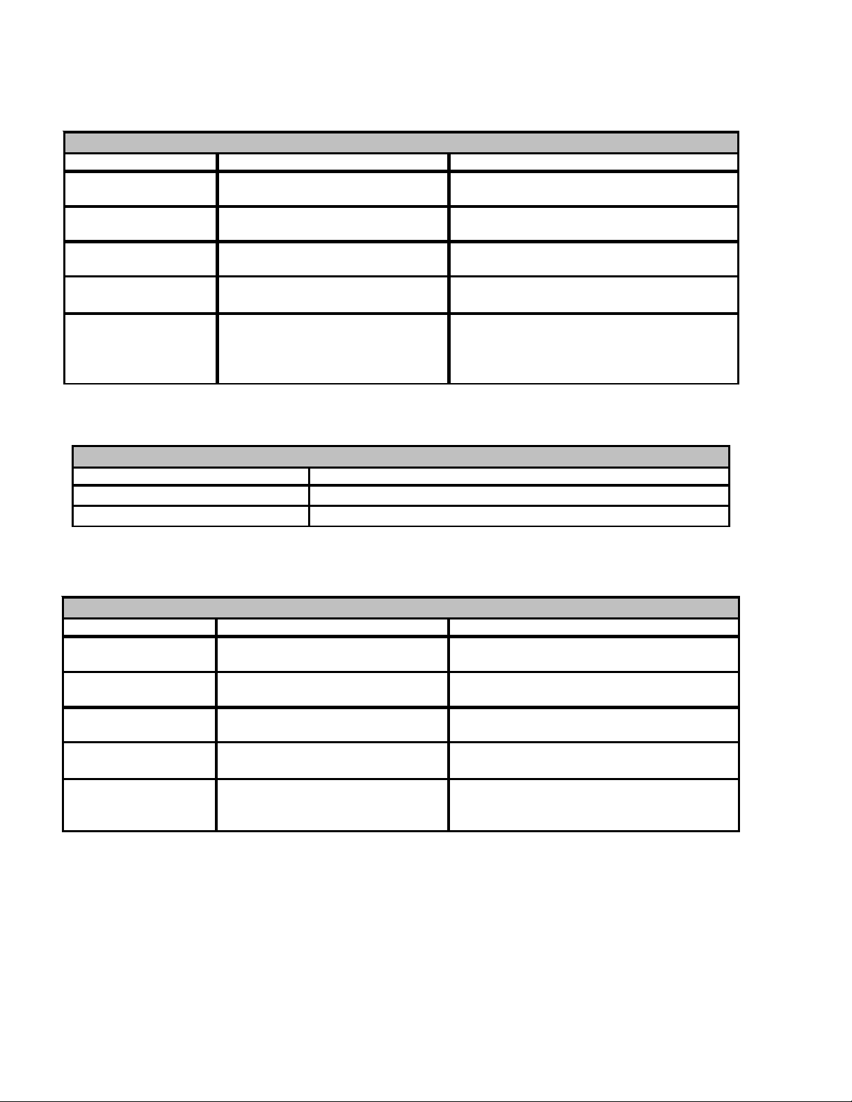
SERVICING
ASXC/ASZC AND DSXC/DSZC ADVANCED USER MENUS, CONT'D
COOL SET- U P
Subm enu Item U ser Modifiable Options Comments
Cool Airflow Trim
(C L TRM)
Cool Airflow Profile
(CL PRFL)
Cool ON Delay
(CL ON)
Co ol OFF De lay
(CL OFF)
Dehumidification Selec t
(DEHUM)
Submenu Item I ndica tion (for Displ ay Only; not User Modifiable)
Mode (MODE) Displays the current air conditioner operating mode
CF M (CFM) Displays the airflow for the current operating mode
-10% to +10% in 2% increm ents ,
default is 0%
A, B, C, or D, default is A Selects the airflow profi le; applies to air
5, 10, 20, or 30 seconds, default is
5 seconds
30, 60, 90, or 120 sec onds, def ault
is 30 s econds
ON or OFF (default is OFF) S electing "OFF" dis ables dehumi dification;
STATUS
Selects the airflow tri m amount; appl ies to air
conditioner only.
conditioner only.
Selects the indoor blower ON del ay; appli es
to ai r conditioner only.
Selects the indoor blower OFF delay; applies
to ai r conditioner only.
selecting "ON" enables dehumidi fication;
applies to air cond itioner only.
HEAT SET-UP
Submenu Item User Modifiable Options Comments
Heat Airf l ow Trim
(HT TRM)
Heat ON Delay
(H T ON)
Heat OFF D elay
(HT OFF)
De fr o st Inte r v a l
(DEFROST)
Compressor Delay
(CMP DLY)
-10% to +10% in 2% increment s,
default is 0%
5, 10, or 15 seconds , default is 5
seconds
30, 50, 70, or 90 sec onds, default
is 30 s econds
30, 60, 90, or 120 minutes , default
is 3 0 minute s.
0, 5, 15, or 30 seconds, default is 5
seconds
Selects the airflow tr im amount; applies to
h eat pump only.
Selects the indoor blower heat ON del ay;
appl ies to heat pump only.
Selects the indoor blower heat OFF delay;
appl ies to heat pump only.
Selects the time interval between defrosts;
appl ies to heat pump only.
Selects the compressor off t ime after a
reversin g val ve shift; applies to heat pump
only.
74
Page 75

SERVICING
S-5 CHECKING CYCLE PROTECTOR
Some models feature a solid state, delay-on make after break
time delay relay installed in the low voltage circuit. This
control is used to prevent short cycling of the compressor
under certain operating conditions.
The component is normally closed (R
interruption will break circuit (R
minutes before resetting.
1. Remove wire from Y1 terminal.
2. Wait for approximately four (4) minutes if machine was running.
With power ON:
to Y1) for approximately three
1
WARNING
Line Voltage now present.
1. Apply 24 VAC to terminals R1 and R2.
2. Should read 24 VAC at terminals Y1 and Y2.
3. Remove 24 VAC at terminals R1 and R2.
4. Should read 0 VAC at Y1 and Y2.
5. Reapply 24 VAC to R1 and R2 - within approximately
three (3) to four (4) minutes should read 24 VAC at Y1 and
Y2.
If not as above - replace relay.
S-6 CHECKING TIME DELAY RELAY
Time delay relays are used in some of the blower cabinets to
improve efficiency by delaying the blower off time. Time
delays are also used in electric heaters to sequence in
multiple electric heaters.
WARNING
Disconnect ALL power before servicing.
1. Tag and disconnect all wires from male spade connections of relay.
2. Using an ohmmeter, measure the resistance across
terminals H1 and H2. Should read approximately 150
ohms.
3. Using an ohmmeter, check for continuity across terminals 3 and 1, and 4 and 5.
4. Apply 24 volts to terminals H1 and H2. Check for
continuity across other terminals - should test continuous. If not as above - replace.
NOTE: The time delay for the contacts to make will be
approximately 20 to 50 seconds and to open after the coil is
de-energized is approximately 40 to 90 seconds.
to Y1). A power
1
OHMMETER
TESTING COIL CIRCUIT
S-7 CHECKING CONTACTOR AND/OR RELAYS
HIGH VOLTAG E!
Disconnect ALL power before servicing
or installing. Multiple power sources
may be present. Failure to do so may
cause pro per ty dam age , pe rs onal inju ry
or death.
The compressor contactor and other relay holding coils are
wired into the low or line voltage circuits. When the control
circuit is energized, the coil pulls in the normally open
contacts or opens the normally closed contacts. When the
coil is de-energized, springs return the contacts to their
normal position.
NOTE: Most single phase contactors break only one side of
the line (L1), leaving 115 volts to ground present at most
internal components.
NOTE: The compressor contactor/relay in ComfortNet
ready equipment is fully integrated into the unitary (UC)
control. The compressor contactor/relay coil on the UC
control is non-serviceable.
1. Remove the leads from the holding coil.
2. Using an ohmmeter, test across the coil terminals.
If the coil does not test continuous, replace the relay or
contactor.
TM
S-8 CHECKING CONTACTOR CONTACTS
WARNING
Disconnect ALL power before servicing.
SINGLE PHASE:
1. Disconnect the wire leads from the terminal (T) side of the
contactor.
2. With power ON, energize the contactor.
WARNING
Line Voltage now present.
75
Page 76
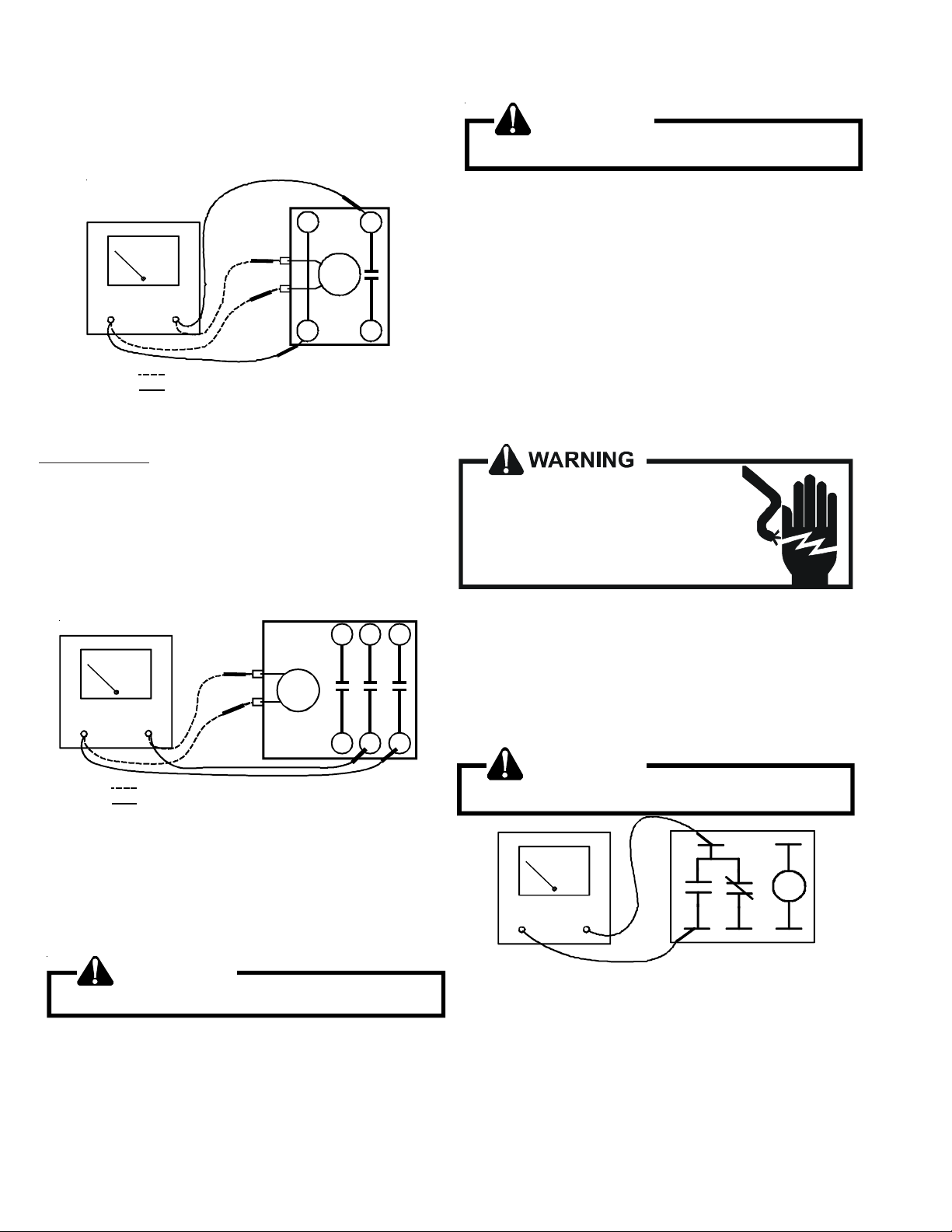
SERVICING
3. Using a voltmeter, test across terminals.
A. L2 - T1 - No voltage indicates CC1 contacts open.
If a no voltage reading is obtained - replace the contactor.
T2
VOLT/OHM
METER
Ohmmeter for testing holding coil
Voltmete r fo r te st in g contacts
TESTING COMPRESSOR CONTACTOR
(Single Phase)
THREE PHASE
Using a voltmeter, test across terminals:
A. L1-L2, L1-L3, and L2-L3 - If voltage is present,
proceed to B. If voltage is not present, check breaker
or fuses on main power supply..
B. T1-T2, T1-T3, and T2-T3 - If voltage readings are not
the same as in "A", replace contactor.
T1
CC
L1L2
WARNING
Line Voltage now present.
3. Measure voltage across on-board compressor contactor/
relay contacts.
A. No voltage indicates the contacts are closed and the
contactor/relay is functioning properly.
B. A reading of approximately half of the supply voltage
(example: 115VAC for 230VAC) indicates the relay is
open. Replace UC control if relay does not close.
NOTE: The unitary (UC) control has a built-in short cycle
delay. Ensure short cycle delay has elapsed before making
voltage measurements.
S-9 CHECKING FAN RELAY CONTACTS
HIGH VOLTAG E!
Disconnect ALL power before servicing
or installing. Multiple power sources
may be present. Failure to do so may
cause pro per ty dam age , pe rs onal inju ry
or death.
T3L3T2
CC
T1
VOLT/OHM
METER
L1
L2
Ohmmeter for testing holding coil
Voltmeter for testing contacts
TESTING COMPRESSOR CONTACTOR
(Three-phase)
S-8A CHECKING UNITARY (UC) CONTROL
COMPRESSOR CONTACTOR/RELAY
CONTACTS
WARNING
Disconnect ALL power before servicing.
1. Connect voltmeter to lugs (L2) and (C).
2. With power ON, provide a call for cool or heat pump to
energize the on-board compressor contactor/relay.
1. Disconnect wire leads from terminals 2 and 4 of Fan Relay
Cooling and 2 and 4, 5 and 6 of Fan Relay Heating.
2. Using an ohmmeter, test between 2 and 4 - should read
open. Test between 5 and 6 - should read continuous.
3. With power ON, energize the relays.
WARNING
Line Voltage now present.
4
OHMMETER
2
5
TESTING FAN RELAY
4. Using an ohmmeter, test between 2 and 4 - should read
continuous . Test between 5 and 6 - should read open.
5. If not as above, replace the relay.
FAN RELAY CONTACTS - UNITARY (UC) CONTROL
Applies to ASXC/ASZC and DSXC/DSZC Models
3
1
76
Page 77
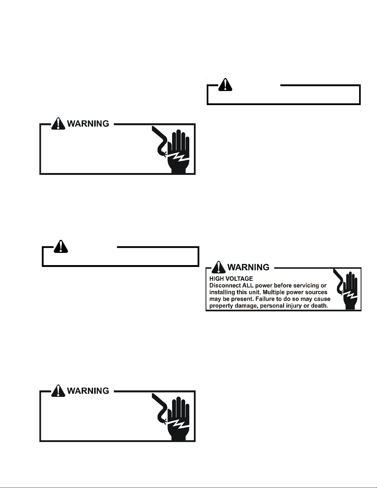
SERVICING
Condenser fan control for the ASXC/ASZC and DSXC/DSZC
models is fully integrated into the UC control. The control
supports one- or two-speed PSC condenser fan motors and
one- or two-speed ECM condenser fan motors.
The fan motor is controlled by two on-board relays. Connection to the fan motor is via a 6-circuit plug connector. Wiring
to the connector is dependant upon the type of condenser fan
motor used. See unit wiring diagram for details.
CHECKING RELAY CONTACTS - PSC FAN MOTOR
HIGH VOL TAGE!
Disconnect ALL power before servicing
or installing. Multiple power sources
may be present. Failure to do so may
cause pr o perty damage , personal in ju r y
or death.
1. Disconnect the motor leads from 6-circuit fan motor wire
harness.
2. Connect a voltmeter between circuit 3 and circuits 2 (low
speed) or 1 (high speed).
NOTE: Circuit 3 is connected directly to L2.
3. Energize the system at low or high stage.
WARNING
Line Voltage now present.
2. Connect a voltmeter between circuit 6 and circuits 3 (low
speed) or 1 (high speed).
NOTE: Circuit 6 is connected directly to 24VAC.
3. Energize the system at low or high stage.
WARNING
Line Voltage now present.
4. The measured voltage between circuit 6 and circuits 3 or
1 should be approximately 0VAC, which indicates the
relay contacts are closed. A voltage measurement of
approximately 24VAC indicates the relay is open. Replace the control if the relay checks open when it should
be closed. See notes and cautions below.
5. Circuit 5 is connected to 24VAC common. The measured
voltage between circuits 6 and 5 should be 24VAC.
NOTE: Ensure any ON delays have expired before making
voltage measurements
CAUTION: Prolonged operation with the condenser fan
motor disconnected will cause the high pressure switch to
trip.
S-10 COPELAND COMFORT ALERT™
DIAGNOSTICS - 3-WIRE MODULE
Applies to ASX /ASZ and DSX/DSZ units
4. The measured voltage between circuit 3 and circuits 2 or
1 should be approximately 0VAC, which indicates the
relay contacts are closed. A voltage measurement of
approximately 115VAC indicates the relay is open.
Replace the control if the relay checks open when it
should be closed. See notes and cautions below.
NOTE: Ensure any ON delays have expired before making
voltage measurements
CAUTION: Prolonged operation with the condenser fan
motor disconnected will cause the high pressure switch to
trip.
CHECKING RELAY CONTACTS - ECM FAN MOTOR
HIGH VOL TAGE!
Disconnect ALL power before servicing
or installing. Multiple power sources
may be present. Failure to do so may
cause pr o perty damage , personal in ju r y
or death.
Comfort Alert™ is self-contained with no required external
sensors and is designed to install directly into the electrical
box of any residential condensing unit that has a Copeland
Scroll™ compressor inside.
Once attached, Comfort Alert provides around-the-clock
monitoring for common electrical problems, compressor
defects and broad system faults. If a glitch is detected, an
LED indicator flashes the proper alert codes to help you
quickly pinpoint the problem. See Diagnostic Table: 3-Wire
Comfort Alert Module on previous page.)
1. Disconnect the motor leads from 6-circuit fan motor wire
harness.
77
Page 78
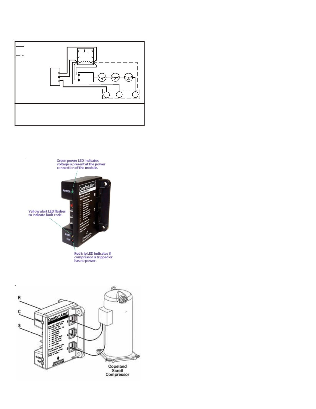
SERVICING
Bold line shows field
installed wiring
Dashed line shows thermostat
demand wiring in system without
HTCO, HPCO, CPCO, and ECB
CC
Comfort Alert
Diagnostics Module
Y
C
R
ECB
LOGIC
HTCO
LPCO HPCO
HTCO High Te mperature Cut Out Switch
HPCO High Pressure Cut Out Switch
LPCO Low Pressure Cut Out Switch
Schematic Abbreviation Descriptions
CC Compressor Contactor
ECB Electronic Control Board
(Defrost or Time Delay)
Wiring Schematic - 3-Wire Comfort Alert Module
Y1RC
78
Page 79
SERVICING
DIAGNOSTICS TABLE: 3-WIRE COMFORT ALERT™ MODULE
Status LED Status LED Description Status LED Troubleshooting Information
Green “P OWER” Module ha s power Supply voltage is present at module terminal s
Red “ T RIP” Thermostat dem and signal 1. Compressor protector is open
Y1 i s pres ent, but the 2. Outdoor uni t power disconnect i s open
com pressor i s not 3. Com pressor circ uit breaker or fus e(s) is open
running 4. Brok en wi re or conn ector is not m aking contact
5. Low pres s ure swit ch open if present i n system
6. Compressor contactor has failed open
Yellow “ ALERT” Long Run Time 1. Low refrigerant c harge
Flash Code 1 Compress or i s 2. Evaporator blower is not runni ng
running ex t rem el y 3. E vaporator c oi l i s frozen
long run cycles 4. Faulty metering device
5. Condenser coil i s dirty
6. Liquid line restriction (filter drier blocked if present in system)
7. Thermos t at is malfuncti oni ng
Yellow “ALERT” System Pressure Trip 1. High head pressure
Flash Code 2 Discharge or suc t i o n 2. Condenser coi l poor air c i rculation (dirty , bloc ked, dam aged)
pressure out of lim i t s or 3. Condenser fan is not running
com pressor overloaded 4. Return ai r duct has substant i al l eak age
5. If low pressure switch present in system,
chec k Flash Code 1 informati on
Yellow “ALERT” Short Cycling 1. Thermost at de mand signal is int erm ittent
Flash Code 3 Compress or i s running 2. Time del ay rel ay or control board defect i ve
only briefl y 3. If high pressure swit ch present go t o F l ash Code 2 informati on
4. If low pressure swit ch present go to Fl as h Code 1 i nformation
Yellow “ ALERT” Locked Rotor 1. Run c apacit or has fai l ed
Flash Code 4 2. Low line voltage (contact utility if voltage at dis c onnect i s l ow)
3. Excessive liquid refrigerant in compressor
4. Compressor beari ngs are sei z ed
Yellow “ALERT” Ope n Circuit 1. Outdoor unit power disconnec t is open
Flash Code 5 2. Compresso r c i rcuit break er or fus e(s) is open
3. Compressor contactor has failed open
4. Hig h pressure sw itch i s open and requires m anual reset
5. Open c i rcuit in compres sor s upply wiring or c onne c t ions
6. Unus ual l y long c om pres sor protec tor reset ti m e
due to ex t rem e am bi ent temperat ure
7. Compressor wi ndings are damaged
Yellow “ ALERT” Open Sta rt Circuit 1. Run capac i t or has failed
Flash Code 6 Current only in run circ ui t 2. Open ci rcuit in compres sor start wiri ng or c onnecti ons
3. Compressor start winding is damaged
Yellow “ ALERT” Open Run Circuit 1. Open circ uit in c om pressor run wiri ng or connect i ons
Flash Code 7 Current only in start ci rcuit 2. Compressor run winding i s damaged
Yellow “ ALERT” W e lded Contactor 1. Compressor contactor has failed cl osed
Flash Code 8 Compress or al ways runs 2. Thermos t at demand signal not connect ed t o m odul e
Yellow “ ALERT” Low Vol tage 1. Control circ uit transformer is overloaded
Flash Code 9 Control c i rc uit < 17V A C 2. Low line voltage (cont act utility if volt age at di sconnect is low)
• Flash Code number corresponds to a number of LED flashes, followed by a pause and then repeated
• TRIP and ALERT LEDs flashing at same time means control circuit voltage is too low for operation.
• Reset ALERT Flash code by removing 24V AC power from module
• Last ALERT Flash code is displayed for 1 minute after module is powered on.
79
Page 80

SERVICING
DIAGNOSTICS - 2-WIRE MODULE
Applies to ASX130[18-60]CA, ASX140[18-36]1CA,
ASX140421DA, and ASX140[48-60]1BA units
Comfort Alert™ is self-contained with no required external
sensors and is designed to install directly into the electrical
box of any residential condensing unit that has a Copeland
Scroll™ compressor inside.
Once attached, Comfort Alert™ provides around-the-clock
monitoring for common electrical problems, compressor
defects and broad system faults. If a glitch is detected, an
LED indicator flashes the proper alert codes to help you
quickly pinpoint the problem. See Diagnostic Table: 2-Wire
Comfort Alert™ Module on previous page.)
NOTE: The 2-wire Comfort Alert™ module does not provide
a diagnostic code 8, Welded Contactor. Additionally, the
2-wire module does not require a manual reset to clear
alert codes.
Bold line shows field
installed wiring
Dashed l ine shows thermostat
demand wiring in system without
HTCO, HPCO, CPCO, and ECB
Comfort Alert
Diagnostics Module
Y
C
HTCO High Temperature Cut Out Switch
HPCO High Pressure Cut Out Switch
LPCO Low Pressure Cut Out Switch
Schematic Abbreviation Descriptions
CC
ECB
LOGIC
CC Compressor Contactor
ECB Electronic Control Board
LPCO
HTCO
R
(Defrost or Time Delay)
HPCO
Wiring Schematic - 2-Wire Comfort Alert™ Module
Y1C
80
Page 81

SERVICING
DIAGNOSTICS TABLE: 2-WIRE COMFORT ALERT™ MODULE
Status LED Status LED De scription S tatus LED Troubleshooting Informa tion
Green “P OW ER” Module has pow e r
Red “TRI P”
Yellow “ALERT” Long Run Tim e
Flash Code 1
Yellow “ALERT” System Pre ssure Trip
Flash Code 2
Yellow “ALERT” Short Cycling
Flash Code 3
Yellow “ALERT” Locke d Rotor
Flash Code 4
Yellow “ALERT” Open Circuit
Flash Code 5
Yellow “ALERT” Open Start Circuit
Flash Code 6
Yellow “ALERT” Open Run Circuit
Flash Code 7
Yellow “ALERT” Low Voltage
Flash Code 9
Thermost at demand s ignal 1. Compress or protector is open
Y1 is present, but the 2. Outdoor unit power disc onnect is open
com press or is not 3. Compress or circuit breaker or fus e(s) is open
running 4. Broken wire or connector is not m ak ing contac t
Compress or is 2. Evaporator blower is not running
running extremely 3. Evaporator coil is frozen
long run cy c les 4. Faulty met ering device
Disc harge or suc tion 2. Condenser coil poor air circ ulation (dirty, block ed, dam aged)
pressure out of limits or 3. Condenser fan is not running
com press or overloaded 4. Return air duct has s ubs tantial leakage
Compress or is running 2. Time delay relay or control board defect ive
only briefly 3. If high pres sure swit ch present go to Flas h Code 2 inform ation
Current only in run circuit 2. O pen c ircuit in com press or start wiring or c onnec tions
Current only in st art circuit 2. Compress or run winding is damaged
Control circuit < 17V A C 2. Low line voltage (contact utility if voltage at disc onnect is low)
Supply voltage is present at module terminals
5. Low press ure switc h open if present in sy s tem
6. Compress or contac tor has failed open
1. Low refrigerant charge
5. Condenser coil is dirty
6. Liquid line restrict ion (filter drier blocked if present in s ys tem )
7. Thermost at is malfunctioning
1. High head pressure
5. If low press ure switc h present in sy s tem ,
check Flas h Code 1 information
1. Thermos t at dem and signal is int ermit tent
4. If low press ure switc h present go to Flash Code 1 info rmation
1. R un capa c i tor h as fail ed
2. Low line voltage (contact utility if voltage at disc onnect is low)
3. Ex c es s ive liquid refrigerant in compress or
4. Compress or bearings are seized
1. Outdoor unit power disc onnect is open
2. Compress or circuit breaker or fus e(s) is open
3. Compress or contac tor has failed open
4. High press ure switc h is open and requires manual reset
5. Open circuit in c om pressor s upply wiring or connect ions
6. Unusually long com press or protector reset time
due to extreme ambient tem perature
7. Compress or windings are damaged
1. R un capa c i tor h as fail ed
3. Compress or start winding is damaged
1. Open circuit in c om pressor run wiring or connections
1. Control circuit transformer is overloaded
• Flash Code number corresponds to a number of LED flashes, followed by a pause and then repeated
• TRIP and ALERT LEDs flashing at same time means control circuit voltage is too low for operation.
• Last ALERT Flash code is displayed for 1 minute after module is powered on.
81
Page 82

SERVICING
S-10A COPELAND COMFORT ALERTTM -
UNITARY (UC) CONTROL DIAGNOSTICS
Applies to ASXC, ASZC, DSXC, and DSZC models
HIGH VO LTAG E!
Disconnect ALL power before servicing
or installing. Multiple power sources
may be present. Failure to do so may
cause property damage, personal injury
or death.
The Copeland Comfort AlertTM diagnostics are fully integrated into the unitary (UC) control. The UC control and
integraged Comfort Alert™ diagnostics provide around-theclock monitoring for common electrical problems, compressor defects and broad system faults. If a problem is detected,
LED indicators flash the proper alert codes to help you
quickly pinpoint the problem.
The diagnostic tables on following pages provide detailed
information regarding the system symptons, indicators (LED
and thermostat), potential problem(s), and corrective actions. The diagnostic information applies to systems wired
as 24VAC traditional (legacy) systems and systems wired as
communicating systems with the CTK0* communicating
thermostat.
82
Page 83

SERVICING
to re p a ir.
consecutive normal
cycles.
cycling 24VAC to
control.
• Turn power OFF prior
• Fault will clear after 30
• Fault may be cleared b y
Co rrective Actions Notes & Cautions
Possible Causes
ComfortNe t™
Th ermostat Only
charge; adjust a s
needed.
li qui d lin e ;
• Verify refri gerant
• R estr iction in li quid l ine.
01 • Low refrigerant charge.
FAULT
repair/replace as
• Check for rest ricte d
failure.
extremely low .
• Ind oor blower m otor
• Indoor therm ostat set
replacement part(s).
• Replace with correct
needed.
mot o r; repa ir/replac e
as needed.
• Check indoor bl ower
to re p a ir.
replacement part(s).
• Turn power OFF prior
• Replace with correct
ther mo s tat se ttin g.
charge; adjust a s
needed.
li qui d lin e ;
repair/replace as
needed.
mot o r; repa ir/replac e
as needed.
switch; repair/replace
• Check indoor
• Verify refri gerant
• Check for rest ricte d
failure.
• Low refrigerant charge.
• R estr iction in li quid l ine.
• Ind oor blower m otor
LP S OPEN 01
• Check indoor bl ower
extremely low .
• Indoor therm ostat set
as needed.
• Check low pressure
to re p a ir.
cycling 24VAC to
control.
• Turn power OFF prior
• Must clear f aul t by
ther mo s tat se ttin g.
charge; adjust a s
• Check indoor
needed.
• Verify refri gerant
• Low refrigerant charge.
• R estr iction in li quid l ine.
• Ind oor blower m otor
01
LPS
LOCKOUT
replacement part(s).
• Replace with correct
li qui d lin e ;
repair/replace as
needed.
mot o r; repa ir/replac e
as needed.
switch; repair/replace
as needed.
• Check for rest ricte d
failure.
• Check indoor bl ower
• Check low pressure
extremely low .
• Indoor therm ostat set
ther mo s tat se ttin g.
• Check indoor
Fault
Description
• Low Side Fault. LO W SIDE
call
presen t;
OFF if no
D i ag n o sti c/Status L ED Codes
OFF 1 Flash OFF ON if call
Green Yellow Red Red Y1 Message Code
Symp toms of A b no rma l Oper ation
(Legacy & ComfortNet™ Thermo s tat)
trips with average run time b etween
trips greater th an 3 hours.
and out do or fan operating at low speed
dia gnosti c /s tatus LED ’s dis pl ay the
• Ve r y long ru n ti me.
• F ou r consecu tive com presso r protector
• Compressor operatin g at hi gh speed
in di ca te d co de.
• Integrated control module
• Low Pressure
ON 1 Flash OFF ON if cal l
• C ompressor and outdoor fan are off.
CO Trip.
call
presen t;
OFF if no
dia gnosti c /s tatus LED ’s dis pl ay the
in di ca te d co de.
• T h erm o stat deman d is present.
• Integrated control module
(3 Tri ps ).
• LPCO Lock out
call
presen t;
OFF if no
ON 1 Flash ON ON if call
same therm ostat demand.
dia gnosti c /s tatus LED ’s dis pl ay the
in di ca te d co de.
S ervice” icon illuminat ed.
“Check Air Conditi one r” or “Check
• C ompressor and outdoor fan are off.
• Lo w pressure switch trip 3 t imes within
• T h erm o stat deman d is present.
• Integrated control module
• ComfortNet™ t hermostat “Call for
Heat P ump ” m es sage.
• ComfortNet™ thermo stat scrolls
83
Page 84

SERVICING
to repair .
consecutive normal
• Turn power OFF prior
cycles.
• Fault w ill clear after 4
cyc li ng 24 VAC to
control.
• Fault may be cleared by
replacemen t part(s).
• Replace with correct
to repair .
replacemen t part(s).
• Turn power OFF prior
• Replace with correct
to repair .
cyc li ng 24 VAC to
control.
• Turn power OFF prior
• Must cl ear fault by
replacemen t part(s).
• Replace with correct
to repair .
consecutive normal
cycles.
cyc li ng 24 VAC to
control.
• Turn power OFF prior
• Fault w ill clear after 4
• Fault may be cleared by
replacemen t part(s).
• Replace with correct
Co rrective Actions Not es & Cautions
ComfortNet™
Fault
condens er coil.
m otor; repair/replace
as ne eded.
moto r wirin g;
r epair/re place as
needed.
m otor capacitor;
r eplace as needed.
condens er coil.
m otor; repair/replace
as ne eded.
moto r wirin g;
r epair/re place as
needed.
m otor capacitor;
r eplace as needed.
condens er coil.
m otor; repair/replace
as ne eded.
moto r wirin g;
r epair/re place as
• Ch eck and clean
• Check outdoo r fan
• Check outdoo r fan
Possible C auses
• Out doo r fan not running.
02 • Blocked condenser coil.
Thermostat Only
FAULT
Message Code
Description
• High Side Fault HI GH SIDE
call
present;
OFF if no
• Check outdoo r fan
• Ch eck and clean
• Check outdoo r fan
• Check outdoo r fan
• Blocked co nd enser coil.
• Out doo r fan not running.
HPS OPEN 02
CO Trip
• High P res s ure
call
present;
OFF if no
• Check outdoo r fan
• Ch eck and clean
• Check outdoo r fan
• Out doo r fan not running.
02 • Blocked condenser coil.
HPS
LOCKOUT
(3 Trips)
• HPCO Lockout
call
present;
OFF if no
needed.
• Check outdoo r fan
• Check outdoo r fan
th ermo stat wiring;
r epair/re place as
needed.
re lay operation;
r eplace control as
m otor capacitor;
r eplace as needed.
• Ch eck thermost at and
demand.
• Faulty compres sor rel ay.
03 • Intermittent thermostat
CYCLE
• Short Cy cling CMP R SHRT
call
present;
OFF if no
needed.
• Ch eck com pressor
84
OFF ON if call
Flashes
Di agno st ic/ S tat u s LED Code s
OFF 2
Green Yellow Red Red Y1
Symp t oms of A b no r mal Ope r at ion
trips with av erage run time bet ween
trips greater than 1 minute an d less tha n
15 min utes .
swit ches are closed.
diagnostic/status LED’s display the
( Legacy & ComfortNet™ Thermo stat)
• Fou r cons e cut i ve c om pres so r prot e cto r
• Low p ressure and hi gh pressure
indicated code.
• In tegrat ed control module
OFF ON if call
Flashes
ON 2
• Compressor and outdoor fan are off.
• T herm ostat dem and is present.
• In tegrat ed control module
diagnostic/status LED’s display the
indicated code.
ON ON if call
Flashes
ON 2
same thermost at demand.
• Compressor and outdoor fan are off.
• Low p ressure switch tr ip 3 times within
OFF ON if call
Flashes
OFF 3
diagnostic/status LED’s display the
indicated code.
Service” icon illuminated.
“Check Air Co nditioner” or “Check
Heat Pump” mes sage.
minutes each.
swit ches are closed.
diagnostic/status LED’s display the
• T herm ostat dem and is present.
• In tegrat ed control module
• ComfortNet™ thermostat “ Call for
• ComfortNet™ thermostat scrolls
• Run time f or last 4 cycles is les s than 3
• Compressor protector has not trip ped.
• Low p ressure and hi gh pressure
indicated code.
• In tegrat ed control module
Page 85

SERVICING
to r e p air .
cyc li ng 24 V AC to
• Turn power OFF prio r
control.
• M ust clear fault by
to r e p air .
normal cycle.
cyc li ng 24 V AC to
control.
replacement part(s).
• Replace with correct
• Turn power OFF prio r
• F ault will clear after 1
• Fault may be cleared b y
replacement part(s).
• Replace with correct
to r e p air .
normal cycle.
cyc li ng 24 V AC to
control.
• Turn power OFF prio r
• F ault will clear after 1
• Fault may be cleared b y
replacement part(s).
• Replace with correct
to r e p air .
cyc li ng 24 V AC to
control.
• Turn power OFF prio r
• M ust clear fault by
replacement part(s).
• Replace with correct
Co rrective Actions Notes & Cautions
ComfortNet™
Fault
operation;
rep a ir/ r ep lace as
needed.
replace as needed.
rep a ir/ r ep lace as
needed.
• Ch eck compressor
Possible Causes
04 • Compre ssor be arings are
Thermostat Only
Message Co de
Description
• L ocked Rotor LOCKED
• Ch eck run capac itor;
• Ch eck wiring;
seized.
capacitor.
wiri ng.
• Fai le d com pr e ssor r u n
• Faulty run capacitor
• Low li n e vo lt a ge .
ROTO R
call
present;
OFF if no
w ith in range on rati ng
• Verify li ne v oltage is
and fuses .
rep a ir/ r ep lace as
needed.
rep a ir/ r ep lace as
needed.
wiring; repair/rep lace
as ne eded.
rep a ir/ r ep lace as
needed.
replace as needed.
rep a ir/ r ep lace as
plate; contact local
u tility is out of range.
• Ch eck circui t br eakers
• Chec k wir i ng to un i t;
• Ch eck compressor;
• Ch eck compressor
protector.
w ir ed to cont r ol .
• Failed compressor
• Compressor not properly
05 • Power i s di scon nec ted .
CIRCUIT
• Open Circ uit OPEN
call
present;
OFF if no
• Ch eck compressor;
• Ch eck run capac itor;
is open.
capacitor.
• Fai le d com pr e ssor r u n
OPEN STA RT 0 6 • Compressor s tart wi nding
Circuit
• Open Start
call
present;
OFF if no
needed.
• Ch eck wiring;
wiri ng.
w ir ed to cont r ol .
• Faulty run capacitor
• Compressor not properly
• Faulty com pres sor wiri ng .
rep a ir/ r ep lace as
needed.
replace as needed.
repair/re place as
• Ch eck compressor;
• Ch eck run capac itor;
is open.
capacitor.
• Fai le d com pr e ssor r u n
06 • Compress or start windi ng
LOCK
OPEN STA RT
Circ ui t Lockout
• Open Start
call
present;
OFF if no
needed.
• Ch eck wiring;
wiri ng.
w ir ed to cont r ol .
• Faulty run capacitor
• Compressor not properly
• Faulty com pres sor wiri ng .
ON ON if call
Flashes
Di agn o st ic/ S t at us L ED C od e s
OFF 4
Green Yellow Red Red Y1
Symp toms of A b nor mal Oper at i on
(Legacy & ComfortNet™ Thermo stat)
cons e c ut ive ti m es .
than 15 seconds.
diagnostic/ status LE D’s disp lay the
indicated co de.
• Compressor and outdoor fan are off.
• Compressor protector trips four
• A ver age ru n time b etween trips is less
• Integrated cont r ol m odu le
Service” icon il luminated.
• Comf ortNet™ thermostat “Call for
OFF ON if call
Flashes
OFF 5
“Check Air Conditio ner” or “Check
Heat P ump” message.
gre a te r tha n 4 ho ur s.
swit ches are closed.
diagnostic/ status LE D’s disp lay the
indicated co de.
• ComfortNet™ thermostat scro lls
• Compressor and outdoor fan are o ff for
• Low pressure and high pressure
• Integrated cont r ol m odu le
Service” icon il luminated.
• Comf ortNet™ thermostat “Call for
OFF ON if call
Flashes
OFF 6
“Check Air Conditio ner” or “Check
Heat P ump” message.
swit ches are closed.
diagnostic/ status LE D’s disp lay the
indicated co de.
• ComfortNet™ thermostat scro lls
• Compressor and outdoor fan are off.
• Low pressure and high pressure
• Integrated cont r ol m odu le
Service” icon il luminated.
• Comf ortNet™ thermostat “Call for
ON ON if call
Flashes
OFF 6
“Check Air Conditio ner” or “C heck
Heat P ump” message.
swit ches are closed.
times with 5 minute delay between each
detection.
diagnostic/ status LE D’s disp lay the
indicated co de.
Service” icon il luminated.
“Check Air Conditio ner” or “Check
• ComfortNet™ thermostat scro lls
• Compressor and outdoor fan are off.
• Low pressure and high pressure
• O pen start circuit has been detected 4
• Integrated cont r ol m odu le
• Comf ortNet™ thermostat “Call for
Heat P ump” message.
• ComfortNet™ thermostat scro lls
85
Page 86

SERVICING
to repair.
norm al cycle.
• Turn po wer OFF prior
• Fault will clear af ter 1
• Fault may be cleared by
cyclin g 24VAC to
cont rol.
rep la cem ent part(s ).
• Replace with co rrect
to repair.
cyclin g 24VAC to
cont rol.
• Turn po wer OFF prior
• Must clea r fau lt by
rep la cem ent part(s ).
• Replace with co rrect
to repair.
voltage less th an 185
• Turn po wer OFF prior
VAC.
• Control detects line
to repair.
voltage greater than 255
• Turn po wer OFF prior
VAC.
• Control detects line
Corrective Actions Notes & Cautions
Possi ble Causes
ComfortNet™
T hermo stat Only
Fault
repair/replace as
needed.
repair/replace as
• Check compres sor;
open.
Message Code
OPEN RUN 07 • Compr e ssor r un win di ng is
D escription
Circuit
• O pe n R un
present;
needed.
• Check wi r ing;
wi re d to control .
• C ompr e s s or not pro p er l y
• Faulty compressor wiring.
call
OFF if no
• Check compres sor;
07 • Com pr e ssor r un winding is
OPEN RUN
• O pe n R un
repair/replace as
needed.
repair/replace as
needed.
• Check wi r ing;
open.
wi re d to control .
• C ompr e s s or not pro p er l y
• Faulty compressor wiring.
LOCK
Circu it L o c kou t
call
present;
OFF if no
and fuses.
connect ed to power
supply as specified on
rating plate.
• Verify unit is
08 • Low line voltage. • Check circuit breakers
VOLT
LOW LI NE
Voltage
• Low Line
call
present;
OFF if no
voltage condition;
• Correct low l ine
voltage condition;
contact local ut il ity if
needed.
connect ed to power
supply as specified on
rating plate.
voltage condition;
contact local ut il ity if
contact local ut il ity if
needed.
• High lin e vo lt age. • C or r e ct high line
08
HIGH LINE
• High L ine
• Verify unit is
VOLT
Voltage
call
present;
OFF if no
needed.
• Correct low l ine
86
Di agnostic /St atus L E D C ode s
G reen Yellow Red Red Y 1
Symp toms of Abnormal Operation
(Legacy & ComfortN e t™ Thermostat)
OFF ON if call
Fl ash es
OFF 7
switches are closed .
di a gno s t ic/status LED ’ s disp l ay t h e
• Compressor and outdoor fan are off.
• Low pressure and high pressure
indicated code.
• Integrated con trol m odule
ON ON if call
Fl ash es
OFF 7
Service” icon illumi nated.
“Check Air Conditioner” or “Ch eck
Heat Pump” mes sa ge.
switches are closed .
times with 5 mi nute delay between each
detecti on.
di a gno s t ic/status LED ’ s disp l ay t h e
indicated code.
• ComfortNet™ the rmostat “Call for
• Com fortNet™ thermostat scrolls
• Compressor and outdoor fan are off.
• Low pressure and high pressure
• Open run circuit has been detected 4
• Integrated con trol m odule
Service” icon illumi nated.
• ComfortNet™ the rmostat “Call for
OFF ON if call
OFF 8
“Check Air Conditioner” or “Ch eck
Heat Pump” mes sa ge.
• Com fortNet™ thermostat scrolls
• A i r co nditione r /he a t pump may ap pe a r
Fl ash es
to be operatin g normally.
(compressor a nd out door fan off).
di a gno s t ic/status LED ’ s disp l ay t h e
• Compressor protector may be open
indicated code.
• Integrated con trol m odule
OFF ON if call
Fl ash es
ON 8
to be operatin g normally.
(compressor a nd out door fan off).
di a gno s t ic/status LED ’ s disp l ay t h e
• A i r co nditione r /he a t pump may ap pe a r
• Compressor protector may be open
indicated code.
• Integrated con trol m odule
Page 87

SERVICING
second ary voltage rises
to repair.
• Fau lt will clear if
• T urn po w e r O F F p rio r
Corrective Actions Notes & Cautions
Possible Causes
ComfortNet™
T h er mo s tat O nl y
Mess age Code
voltage condition.
• Check f use.
• Correct low second ary
• Check trans f ormer;
voltage less than 18 VAC.
• T ransforme r overloaded .
• Low line voltage.
09 • Control detects secon dary
LO W
VO L T
SECOND
rep la c ement pa r t(s).
above 2 1V AC .
replace if nee ded.
• Replace wit h correct
• T urn po w e r O F F p rio r
repair/replace as
• Check compressor;
start windings.
• No current through run or
Not
displa ye d
Not displayed
• Faul t may be cleared by
• Fau lt will clear after 1
needed.
repair/replace as
needed.
• Check wiring;
is ope n.
• Compressor run winding
w ired to control.
• Compressor not properl y
cycling 2 4V AC to
norm al cycle.
to repair.
rep la c ement pa r t(s).
con trol.
• Replace wit h correct
replace as needed.
• Check r un capacitor;
capacitor.
• F a ulty com p re sso r wi ring .
• F a iled co m p ressor ru n
wiri ng .
• F aulty run capacitor
Fault
D escriptio n
Di a gn o s tic/ Status L E D Codes
Sy mp to m s of Abnormal Opera tion
(Lega cy & Comfo rtN et™ Th ermostat)
• Low P ilo t
OFF ON if call
OFF 9
G reen Yell ow Red Red Y 1
• Air conditioner/heat pum p may appear
Voltage
call
present;
OFF i f no
Fl ash es
to be operating normally.
diagnostic/status LED’s display the
i ndicated code.
• Integrated con trol m odule
Open
• Com p Protector
present;
OFF ON ON ON if call
• Com pressor i s of f.
• Integrated con trol m odule
call
OFF i f no
diagnostic/status LED’s display the
i ndicated code.
87
Page 88
SERVICING
3YMPTOMSOF
!BNORMAL/PERATION
,EGACY#OMFORT.ET
4HERMOSTAT
sIntegrated control
module diagnostic/status
LED display shows the
indicated code.
s#OMFORT.ETTHERMOSTAT
displays ‘---‘ in the
temperature display area.
sHeat pump fails to operate
in heating mode.
sIntegrated control
module diagnostic/status
LED display shows the
indicated code.
s#OMFORT.ETTHERMOSTAT
displays error message.
sAir conditioner/heat pump
fails to operate.
sIntegrated control
module diagnostic/status
LED display shows the
indicated code.
sAir conditioner/heat pump
fails to operate.
sIntegrated control
module diagnostic/status
LED display shows the
indicated code.
sAir conditioner/heat pump
fails to operate.
sIntegrated control
module diagnostic/status
LED display shows the
indicated code.
s#OMFORT.ETTHERMOSTAT
displays error message.
s Air conditioner/heat
pump operates at reduced
performance.
sAir conditioner/heat pump
operating at low stage
when expected to operate
at high stage.
sIntegrated control
module diagnostic/status
LED display shows the
indicated code.
3934%-42/5",%3(//4).'
5.)4!29$)!'./34)##/$%3
$IAGNOSTIC3TATUS
,%$$ISPLAY#ODES
$IGIT $IGIT $IGIT -ESSAGE #ODE
",!.+ A 2 s Outdoor air
",!.+ A3sOutdoor coil
",!.+ E5sOpen fuse ",/7.
",!.+ EEsBoard mis-
",!.+ b0sCirculator
",!.+ b9sAirflow is
&AULT
$ESCRIPTION
temp sensor
fault
temp sensor
fault
operation
blower motor
is not running
when it
should be
running.
lower than
demanded
#OMFORT.ET
4HERMOSTAT/NLY
AIR
3%.3/2
FLT
COIL
3%.3/2
FLT
FUSE
).4%2.!,
FAULT
MOTOR
./425.
LOW ID
AIRFLOW
4-
A2 sShorted sensor.
A3 s Shorted sensor
E5 sShort in low
EE sCompressor
b0 s Indoor blower
b9 s Indoor blower
0OSSIBLE
#AUSES
sOpen sensor.
sSensor
disconnected.
sSensor out of
range.
sOpen sensor.
sSensor.
disconnected.
sSensor out of
range.
voltage wiring.
relay contacts
welded.
motor problem.
sCommunications
error between
indoor and
outdoor unit.
motor problem
Blocked filters.
s
sRestrictive/
undersized
ductwork
sIndoor/ outdoor
unit miss-match.
PCBHR104
#ORRECTIVE
!CTIONS
sCheck sensor
connection.
sReplace open/
shorted sensor.
sCheck sensor
connection.
sReplace open/
shorted sensor.
sLocate and
correct short
in low voltage
wiring.
sReplace control. sTurn power OFF prior
sCheck indoor
blower motor.
sCheck indoor
blower motor
wiring.
sCheck indoor unit
control.
sRepair/ replace
any faulty wiring.
sRepair/ replace
indoor blower
motor or control.
sCheck indoor
blower motor.
sCheck filters;
clean/replace as
needed.
sCheck ductwork;
resize as needed.
sVerify indoor and
outdoor units are
properly matched.
.OTES
#AUTIONS
sTurn power OFF prior
to repair.
sReplace with correct
replacement part.
sTurn power OFF prior
to repair.
sReplace with correct
replacement part.
sTurn power OFF prior
to repair.
sReplace fuse with
3-amp automotive type.
to repair
sReplace with correct
replacement part.
sTurn power OFF prior
to repair.
sApplies only to fully
communicating system
USING#OMFORT.ET
thermostat.
sReplace with correct
replacement part.
sTurn power OFF prior
to repair.
sApplies only to fully
communicating system
USING#OMFORT.ET
thermostat.
sReplace with correct
replacement part. See
specification sheet(s)
for airflow requirements
and maximum external
static pressure.
sSee specification
sheets for approved
system matches.
88
Page 89

SERVICING
5.)4!29$)!'./34)##/$%3
3YMPTOMSOF
!BNORMAL/PERATION
,EGACY#OMFORT.ET
4HERMOSTAT
$IAGNOSTIC3TATUS
,%$$ISPLAY#ODES &AULT
$ESCRIPTION
#OMFORT.ET4-
4HERMOSTAT/NLY 0OSSIBLE
#AUSES
#ORRECTIVE
!CTIONS
.OTES
#AUTIONS
$IGIT $IGIT $IGIT -ESSAGE #ODE
sAir conditioner/heat pump
fails to operate.
sIntegrated control
module diagnostic/status
LED display shows the
indicated code.
s#OMFORT.ETTHERMOSTAT
displays error message.
",!.+ d0sData not yet
ON.ETWORK
./.%4
DATA
d0 sAir conditioner/
heat pump is
wired as part of
a communicating
system and
integrated control
module does
not contain any
shared data.
sVerify
system type
(communicating
or legacy)
sPopulate shared
data using
memory card
sWire system as
legacy system
sTurn power OFF prior
to repair.
sUse memory card for
your specific model.
sInsert memory card
BEFORE turning power
/.-EMORYCARDMAY
be removed after data
is loaded. Turn power
OFF before removing
memory card.
sError code will
be cleared once
data is loaded.
Applies only to fully
communicating system
USING#OMFORT.ET
thermostat.
sAir conditioner/heat pump
fails to operate.
sIntegrated control
module diagnostic/status
LED display shows the
indicated code.
s#OMFORT.ETTHERMOSTAT
displays error message.
",!.+ d1sInvalid Data
ON.ETWORK
).6!,)$
DATA
d1 s Air conditioner/
heat pump is
wired as part of
a communicating
system and
integrated control
module contains
invalid shared
data or network
data is invalid for
the integrated
control module.
sVerify
system type
(communicating
or legacy).
sPopulate correct
shared data using
memory card.
sWire system as
legacy system.
sTurn power OFF prior
to repair.
sUse memory card for
your specific model.
sInsert memory card
BEFORE turning power
/.-EMORYCARDMAY
be removed after data
is loaded. Turn power
OFF before removing
memory card.
sError code will
be cleared once
data is loaded.
Applies only to fully
communicating system
USING#OMFORT.ET
thermostat.
sAir conditioner/heat pump
fails to operate.
sAir conditioner/heat pump
operating at reduced
performance.
sAir conditioner/heat pump
operating at low stage
when expected to operate
at high stage.
sIntegrated control
module diagnostic/status
LED display shows the
indicated code.
s#OMFORT.ETTHERMOSTAT
displays error message.
",!.+ d2s System
Mis-Match
).6!,)$
SYSTEM
d2 s Air conditioner/
heat pump is
wired as part of
a communicating
system and
outdoor unit
requires airflow
greater than
indoor unit’s
airflow capability.
sShared data is
incompatible
with the system
or missing
parameters.
sVerify system type
(communicating
or legacy).
sVerify shared
data is correct
for your specific
model; repopulate data if
required.
sWire system as
legacy system.
sTurn power OFF prior
to repair.
sUse memory card for
your specific model.
sInsert memory card
BEFORE turning power
/.-EMORYCARDMAY
be removed after data
is loaded. Turn power
OFF before removing
memory card.
sError code will
be cleared once
data is loaded.
Applies only to fully
communicating system
USING#OMFORT.ET
thermostat.
PCBHR104
89
Page 90

SERVICING
3YMPTOMSOF
!BNORMAL/PERATION
,EGACY#OMFORT.ET
4HERMOSTAT
s Air conditioner/heat pump
fails to operate.
sIntegrated control module
diagnostic/status LED
display shows the indicated
code.
s#OMFORT.ETTHERMOSTAT
displays error message.
sAir conditioner/heat pump
fails to operate.
sIntegrated control
module diagnostic/status
LED display shows the
indicated code.
s#OMFORT.ETTHERMOSTAT
displays error message.
s Very long run time.
sFour consecutive
compressor protector
trips with average run
time between trips greater
than 3 hours.
sCompressor operating at
high speed and outdoor fan
operating at low speed
sIntegrated control
module diagnostic/status
LED display shows the
indicated code.
sCompressor and outdoor
fan are off.
sThermostat demand is
present.
sIntegrated control
module diagnostic/status
LED display shows the
indicated code.
5.)4!29$)!'./34)##/$%3
$IAGNOSTIC3TATUS
,%$$ISPLAY#ODES &AULT
$IGIT $IGIT $IGIT -ESSAGE #ODE
",!.+ d3sConfiguration
",!.+ d4s Invalid
",!.+ 01sLow Side
",!.+ 01sLow Pressure
$ESCRIPTION
Mis-match
Memory
Card Data
Fault
Cut Out Trip
#OMFORT.ET4-
4HERMOSTAT/NLY 0OSSIBLE
).6!,)$
#/.&)'
).6!,)$
MC DATA
LOW SIDE
FAULT
,03/0%. 01 s Low refrigerant
d3 s Shared data sent
d4 sShared data on
01 sLow refrigerant
#AUSES
to integrated
control module
does not match
hardware
configuration.
memory card has
been rejected.
charge.
sRestriction in
liquid line.
sIndoor blower
motor failure.
sIndoor
thermostat set
extremely low.
charge.
sRestriction in
liquid line.
sIndoor blower
motor failure.
sIndoor
thermostat set
extremely low.
PCBHR104
#ORRECTIVE
!CTIONS
sVerify
system type
(communicating
or legacy).
sVerify shared
data is correct
for your specific
model; repopulate data if
required.
sWire system as
legacy system.
sVerify
system type
(communicating
or legacy).
sVerify shared
data is correct
for your specific
model; repopulate data if
required.
sWire system as
legacy system.
sVerify refrigerant
charge; adjust as
needed.
sCheck for
restricted liquid
line; repair/
replace as
needed.
sCheck indoor
blower motor;
repair/replace as
needed.
sCheck indoor
thermostat setting.
sVerify refrigerant
charge; adjust as
needed.
sCheck for
restricted liquid
line; repair/
replace as
needed.
sCheck indoor
blower motor;
repair/replace as
needed.
sCheck low
pressure switch;
repair/replace as
needed.
sCheck indoor
thermostat setting.
.OTES
#AUTIONS
sTurn power OFF prior
to repair.
sUse memory card for
your specific model.
sInsert memory card
BEFORE turning power
/.-EMORYCARDMAY
be removed after data
is loaded. Turn power
OFF before removing
memory card.
sError code will
be cleared once
data is loaded.
Applies only to fully
communicating system
USING#OMFORT.ET
thermostat.
sTurn power OFF prior
to repair.
sUse memory card for
your specific model.
sInsert memory card
BEFORE turning power
/.-EMORYCARDMAY
be removed after data
is loaded. Turn power
OFF before removing
memory card.
sError code will be
cleared once data is
loaded.
sTurn power OFF prior
to repair.
sFault will clear after 30
consecutive normal
cycles.
sFault may be cleared
by cycling 24VAC to
control.
sReplace with correct
replacement part(s).
sTurn power OFF prior
to repair.
sReplace with correct
replacement part(s).
90
Page 91

SERVICING
Compressor and outdoor
f
.
Low pressure switch
trip 3 times within same
thermostat demand.
Thermostat demand is
present.
Integrated control
module diagnostic/status
LED display shows the
indicated code.
displays error message.
L1Low Pressure
Cut Out
Lockout
(3 T rips)
LPS 01 Low refrigerant
charge.
Restriction in
liquid line.
Indoor blower
motor failure.
Indoor
thermostat set
extremely low.
Verify refrigerant
charge; adjust as
needed.
Check for
restricted liquid
line; repair/replace
as needed.
Check indoor
blower motor;
repair/replace as
needed.
Check low
pressure switch;
repair/replace as
needed.
Check indoor
thermostat setting.
Turn power OFF prior
to repair.
Must clear fault by
cycling 24VAC to
control.
Replace with correct
replacement part(s).
Four consecutive
compressor protector trips
with average run time
between trips greater than
1 minute and less than 15
minutes.
Low pressure and high
pressure switches are
closed.
Integrated control
module diagnostic/status
LED display shows the
indicated code.
02High Side
Fault
HIGH SIDE
FAULT
02 Blocked
condenser coil.
Outdoor fan not
running.
Check and clean
condenser coil.
Check outdoor
fan motor; repair/
replace as
needed.
Check outdoor
fan motor wiring;
repair/replace as
needed.
Check outdoor
fan motor
capacitor; replace
as needed.
Turn power OFF prior
to repair.
Fault will clear after 4
consecutive normal
cycles.
Fault may be cleared
by cycling 24VAC to
control.
Replace with correct
replacement part(s).
Compressor and outdoor
f
.
Thermostat demand is
present.
Integrated control
module diagnostic/status
LED display shows the
indicated code.
02High
Pressure
Cut Out
Trip
02 Blocked
condenser coil.
Outdoor fan not
running.
Check and clean
condenser coil.
Check outdoor
fan motor; repair/
replace as
needed.
Check outdoor
fan motor wiring;
repair/replace as
needed.
Check outdoor
fan motor
capacitor; replace
as needed.
Turn power OFF prior
to repair.
Replace with correct
replacement part(s).
Compressor and outdoor
f
.
Low pressure switch
trip 3 times within same
thermostat demand.
Thermostat demand is
present.
Integrated control
module diagnostic/status
LED display shows the
indicated code.
displays error message.
L2High
Pressure
Cut Out
Lockout
(3 T rips)
HPS
02 Blocked
condenser coil.
Outdoor fan not
running.
Check and clean
condenser coil.
Check outdoor
fan motor; repair/
replace as
needed.
Check outdoor
fan motor wiring;
repair/replace as
needed.
Check outdoor
fan motor
capacitor; replace
as needed.
Turn power OFF prior
to repair.
Must clear fault by
cycling 24VAC to
control.
Replace with correct
replacement part(s).
Digit 3 Digit 2 Digit 1
PCBHR104
91
Page 92
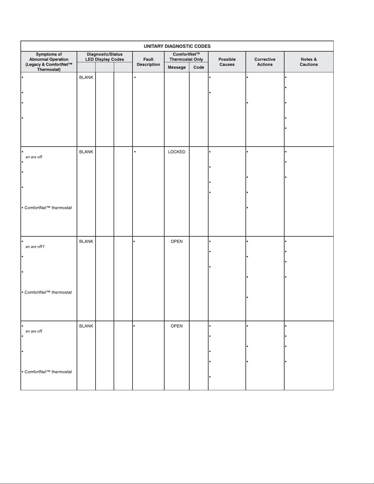
SERVICING
1
PCBHR104
Digit 3 Digit 1Digit 2
Run time for last 4 cycles
is less than 3 minutes
each.
Compressor protector has
not tripped.
Low pressure and high
pressure switches are
closed.
Integrated control
module diagnostic/status
LED display shows the
indicated code.
Compressor and outdoor
f
Compressor protector trips
four consecutive times.
Average run time between
trips is less than 15
seconds.
Integrated control
module diagnostic/status
LED display shows the
indicated code.
displays error message.
Compressor and outdoor
f
4 hours.
Low pressure and high
pressure switches are
closed.
Integrated control
module diagnostic/status
LED display shows the
indicated code.
displays error message.
Compressor and outdoor
f
Low pressure and high
pressure switches are
closed.
Integrated control
module diagnostic/status
LED display shows the
indicated code.
displays error message.
.
or greater than
.
03Short Cycling CMPR
04Locked Rotor
05Open Circuit
06Open Start
Circuit
SHRT
CYCLE
ROTOR
CIRCUIT
START
03 Intermittent
thermostat
demand.
Faulty
compressor
relay.
04
Compressor
bearings are
seized.
Failed
compressor run
capacitor.
Faulty run
capacitor wiring.
Low line voltage.
05
Power is
disconnected.
Failed
compressor
protector.
Compressor not
properly wired to
control.
06
Compressor start
winding is open.
Failed
compressor run
capacitor.
Faulty run
capacitor wiring.
Compressor not
properly wired to
control.
Faulty
compressor
wiring.
Check thermostat
and thermostat
wiring; repair/
replace as
needed.
Check
compressor
relay operation;
replace control as
needed.
Check
compressor
operation; repair/
replace as
needed.
Check run
capacitor; replace
as needed.
Check wiring;
repair/replace as
needed.
Verify line voltage
is within range
on rating plate;
contact local
utility is out of
range.
Check circuit
breakers and
fuses.
Check wiring
to unit; repair/
replace as
needed.
Check
compressor;
repair/replace as
needed
Check
compressor
wiring; repair/
replace as
needed.
Check
compressor;
repair/replace as
needed.
Check run
capacitor; replace
as needed.
Check wiring;
repair/replace as
needed.
Turn power OFF prior
to repair.
Fault will clear after 4
consecutive normal
cycles.
Fault may be cleared
by cycling 24VAC to
control.
Replace with correct
replacement part(s).
Minimum compressor
runt time is changed
from 30 seconds to 3
minutes.
Turn power OFF prior
to repair.
Must clear fault by
cycling 24VAC to
control.
Replace with correct
replacement part(s).
Turn power OFF prior
to repair.
Fault will clear after
normal cycle.
Fault may be cleared
by cycling 24VAC to
control.
Replace with correct
replacement part(s).
Turn power OFF prior
to repair.
Fault will clear after 1
normal cycle.
Fault may be cleared
by cycling 24VAC to
control.
Replace will correct
replacement part(s).
92
Page 93
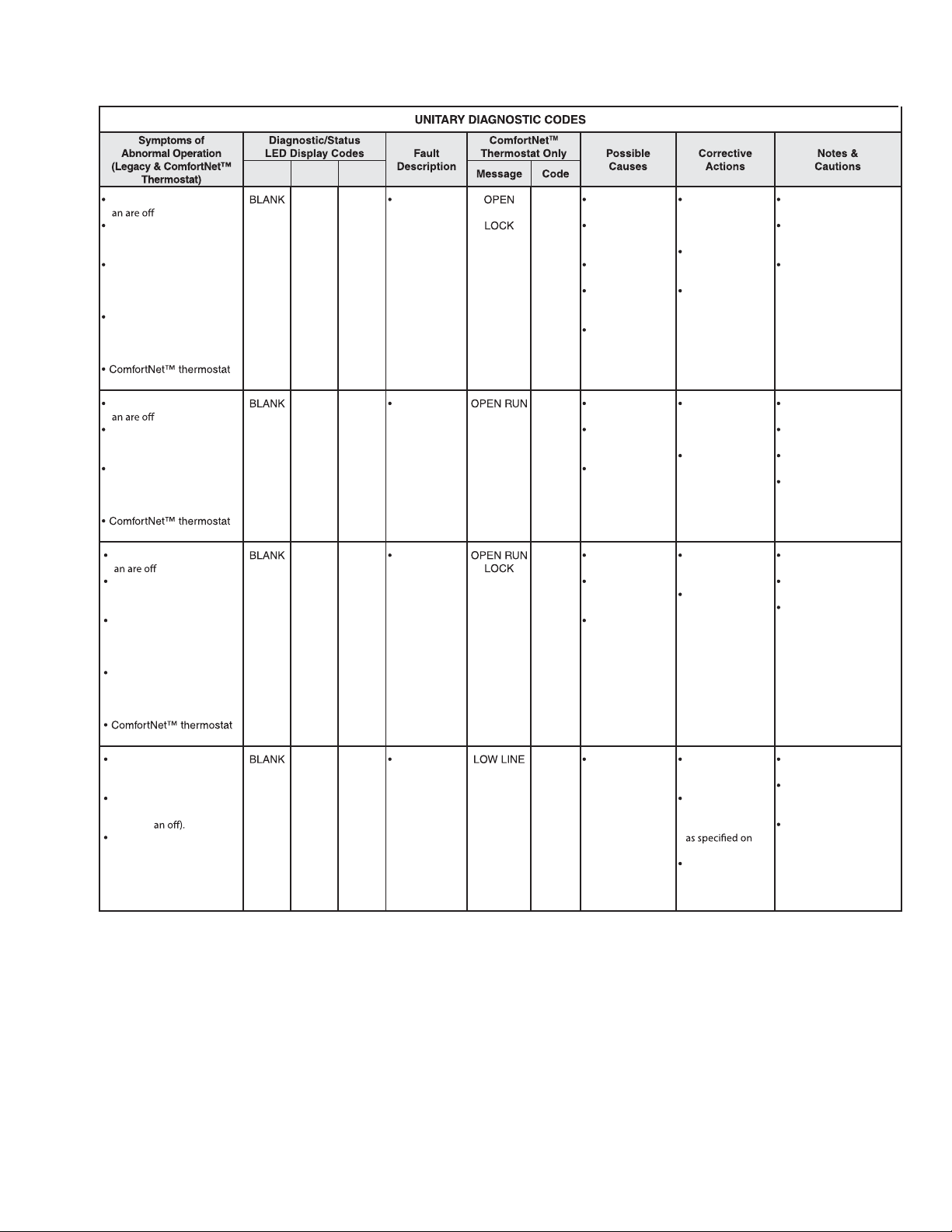
SERVICING
Compressor and outdoor
f .
Low pressure and high
pressure switches are
closed.
Open start circuit has been
detected 4 times with 5
minute delay between each
detection.
Integrated control
module diagnostic/status
LED display shows the
indicated code.
displays error message.
L6Open Start
Circuit
Lockout
START
06 Compressor start
winding is open.
Failed
compressor run
capacitor.
Faulty run
capacitor wiring.
Compressor not
properly wired
to control.
Faulty
compressor
wiring.
Check
compressor;
repair/replace as
needed.
Check run
capacitor; replace
as needed.
Check wiring
repair/replaced
as needed.
Turn power OFF prior
to repair
Must clear fault by
cycling 24VAC to
control.
Replace with correct
replacement part(s).
Compressor and outdoor
f
.
Low pressure and high
pressure switches are
closed.
Integrated control
module diagnostic/status
LED display shows the
indicated code.
displays error message.
07Open Run
Circuit
07 Compressor run
winding is open.
Compressor not
properly wired
to control.
Faulty
compressor
wiring.
Check
compressor;
repair/replace as
needed.
Check wiring;
repair/replace as
needed.
Turn power OFF prior
to repair.
Fault will clear after 1
normal cycle.
Fault may be cycling
24VAC to control.
Replace with correct
replacement part(s).
Compressor and outdoor
f .
Low pressure and high
pressure switches are
closed.
Open run circuit has been
detected 4 times with 5
minute delay between
each detection.
Integrated control
module diagnostic/status
LED display shows the
indicated code.
displays error message.
L7Open Run
Circuit
Lockout
07 Compressor run
winding is open.
Compressor not
properly wired
to control.
Faulty
compressor
wiring.
Check compressor; repair/replace as needed.
Check wiring;
repair/replace as
needed.
Turn power OFF prior
to repair.
Must clear fault by cycling 24VAC to control.
Replace with correct
replacement part(s).
Air conditioner/heat
pump may appear to be
operating normally.
Compressor protector may
be open (compressor and
outdoor f
Integrated control
module diagnostic/status
LED display shows the
indicated code.
L8Low Line
Voltage
VOLT
08
Low line voltage. Check circuit
breakers and
fuses.
Verify unit is
connected to
power supply
rating plate.
Correct low line
voltage condition;
contact local
utility if needed.
Turn power OFF prior
to repair.
Control detects line
voltage less than
185 VA C.
Fault will clear if line
voltage increases
above 185 VAC.
Digit 3 Digit 2 Digit 1
PCBHR104
93
Page 94

SERVICING
PCBHR104
Air conditioner/heat
pump may appear to be
operating normally.
Compressor protector
may be open (compressor
and outdoor f
Integrated control
module diagnostic/status
LED display shows the
indicated code.
Air conditioner/heat
pump may appear to be
operating normally.
Integrated control
module diagnostic/status
LED display shows the
indicated code.
Integrated control
module diagnostic/status
LED display shows the
indicated code.
Air conditioner/heat
pump may appear to be
operating normally.
Compressor protector
may be open (compressor
and outdoor f
Integrated control
module diagnostic/status
LED display shows the
indicated code.
.
Digit 3
Digit 1Digit 2
H8High Line
Voltage
09Low Pilot
Voltage
P0Comp
Protector
Open
08
08
09
08
High line
voltage
Control detects
secondary
voltage less
than 18 VAC.
Transformer
overloaded.
Low line voltage.
start windings.
Compressor
run winding is
open.
Compressor not
properly wired to
control.
Faulty
compressor
wiring.
Failed
compressor run
capacitor.
Faulty run
capacitor wiring.
VOLT
LOW
VOLT
displayed displayed through run or
VOLT AGE
Correct high line
voltage condition;
contact local utility
if needed.
Verify unit is
connected to power
on rating plate.
Check fuse.
Correct low secondary voltage condition.
Check transformer;
replace if needed.
Check compressor;
repair/replace as
needed.
Check wiring; repair/
replace as needed.
Check run capacitor; replace as
needed.
Check circuit
breaker and fuses.
Verify unit is connected to power
on rating plate.
Turn power OFF prior
to repair.
Control detects line
voltage greater than
255 VA C.
Fault will clear if line
voltage decreases
below 255 VAC.
T urn power OFF prior to
repair.
Fault will clear if
secondary voltage rises
above 21V AC.
Replace with correct
replacement part(s).
Turn power OFF prior
to repair.
Fault will clear after 1
normal cycle.
Fault may be cleared
by cycling 24VAC to
control.
Replace with correct
replacement part(s).
Turn power OFF prior
to repair.
Control detects line
voltage less than
185 VA C.
Fault will clear if line
voltage increases
above 185 VAC.
94
Page 95

SERVICING
PCBHR104
7 SEGMENT LED
(DS2)
0 n Standby
0 1 Low Pressure CO Trip
0 1 Low Side Fault
0 2 High Pressure CO Trip
0 2 High Side Fault
0 3 Short Cycling
0 4 Locked Rotor
0 5 Open Circuit
0 6 Open Start Circuit
0 7 Open Run Circuit
0 8 No Line Voltage
0 9 Low Pilot Voltage
88 Power Up
A 2 Outdoor Air Temp Sensor Fault
A 3 Outdoor Coil Temp Sensor Fault *
b 0 No Indoor Airflow
b 9 I nadequate Airflow
C 3 Cool Mode Short Cycle Timer
C 1 Low Cool
C 2 High Cool
dF Defrost *
d t Max Defrost Time *
d E Forced Defrost *
d 0 Data not yet on Network
d 1 Invalid Data on Netw ork
d 2 System Mis-Match
d 3 Configuration Mis-Match
d 4 Inv alid Memory Card Data
E E Board Misoperation
E 5 Open Fuse
F t Fiel d Test Mode
H 8 High Line Voltage
L 1 LPCO Lockout (3 Trips)
L 2 HPCO Lockout (3 Trips)
L 6 Open Start Circuit Lockout
L 7 Open R un Circuit Lockout
L 8 Low Line Voltage
P 3 Heat Mode Short Cycle Timer *
P 1 Low Heat *
P 2 High Heat *
P 0 Comp Pr otector Open
Pd Pump Down
7 S EG MENT LED
(DS1)
DESCRIPTION OF CONDITION
* CODE USED ON HEAT PUMP MODELS ONLY
NOTE 1: DS1 , DS2 A ND DS3 ARE LAB EL E D ON THE CONTROL ABOVE EA CH 7
SEGMENT LED DISPLAY
NOTE 2: 7 SEGMENT LED DISPLAY DS3 IS NOT USED
0140M00407-A
95
Page 96

SERVICING
S-10B COPELAND CORESENSE™
DIAGNOSTICS - 3-WIRE MODULE
Applies to ASX /ASZ and DSX/DSZ units
The CoreSense™ module is self-contained with no required
external sensors and works with any residential condensing
unit that has a Copeland Scroll™ compressor inside.
Once attached, CoreSense provides around-the-clock monitoring for common electrical problems, compressor defects
and broad system faults. If a glitch is detected, an LED
indicator flashes the proper alert codes to help you quickly
pinpoint the problem. See Diagnostic Table: 3-Wire
CoreSense™ Module on following pages.)
Wiring Schematic - 3-Wire CoreSense™ Alert Module
Reset
Switch
One
Current
Sensor
Run/Alert
LED
Trip/Lock-Out
Red LED
Protection
Output
Data Port
DIAGNOSTICS - 2-WIRE MODULE
Applies to ASX130[18-60]CA, ASX140[1836]1CA, ASX140421DA, and ASX140[48-60]1BA
units
Indoor
Unit
HTCO High Temperature Cut Out Switch
HPCO High Pressure Cut Out Switch
LPCO Low Pressure Cut Out Switch
C
Y
Schematic Abbreviation Descriptions
CC Compressor Contactor
ECB Electronic Control Board
(Defrost or Time Delay)
The CoreSense™ module is self-contained with no required
external sensors and works with any residential condensing
unit that has a Copeland Scroll™ compressor inside.
Once attached, CoreSense™ provides around-the-clock
monitoring for common electrical problems, compressor
defects and broad system faults. If a glitch is detected, an
LED indicator flashes the proper alert codes to help you
quickly pinpoint the problem. See Diagnostic Table: 2-Wire
Comfort Alert™ Module on following pages.)
Schematic Abbreviation Descriptions
HTCO High Temperature Cut Out Switch
HPCO High Pressure Cut Out Switch
LPCO Low Pressure Cut Out Switch
CC Compressor Contactor
ECB Electronic Contr ol Board
(Defrost or T im e Delay)
Wiring Schematic - 2-Wire CoreSense™ Module
96
Page 97

SERVICING
DIAGNOSTICS TABLE: CORESENSE™ MODULE
Flash code number corresponds to the number of LED flashes, followed by a pause and then repeated.
TRIP and ALERT LEDs flashing at the same time mean control circuit voltage is too low for operation.
97
Page 98

SERVICING
DIAGNOSTICS TABLE: CORESENSE™ MODULE (cont.)
Flash code number corresponds to the number of LED flashes, followed by a pause and then repeated.
TRIP and ALERT LEDs flashing at the same time mean control circuit voltage is too low for operation.
98
Page 99

SERVICING
Table 1 - Quick Reference Table
99
Page 100

SERVICING
S-11 CHECKING LOSS OF CHARGE PROTEC-
TOR
(Heat Pump Models)
The loss of charge protectors senses the pressure in the
liquid line and will open its contacts on a drop in pressure. the
low pressure control will automatically reset itself with a rise
in pressure.
The low pressure control is designed to cut-out (open) at
approximately 21 PSIG. It will automatically cut-in (close) at
approximately 50 PSIG.Test for continuity using a VOM and
if not as above, replace the control.
S-12 CHECKING HIGH PRESSURE CONTROL
HIGH VOLTAGE!
Disconnect A LL power before servicing
or installing. Multiple power sources
may be present. Failure to do so may
cause pr o pe r ty da m a ge , pe r s on al in ju ry
or death.
The high pressure control capillary senses the pressure in the
compressor discharge line. If abnormally high condensing
pressures develop, the contacts of the control open, breaking
the control circuit before the compressor motor overloads.
This control is automatically reset.
1. Using an ohmmeter, check across terminals of high
pressure control, with wire removed. If not continuous,
the contacts are open.
2. Attach a gauge to the dill valve port on the base valve.
With power ON:
WARNING
Line Voltage now present.
3. Start the system and place a piece of cardboard in front
of the condenser coil, raising the condensing pressure.
4. Check pressure at which the high pressure control cutsout. If it cuts-out at 610 PSIG ± 10 PSIG, it is operating
normally (See causes for high head pressure in Service
Problem Analysis Guide). If it cuts out below this pressure
range, replace the control.
S-13 CHECKING LOW PRESSURE CONTROL
The low pressure control senses the pressure in the suction
line and will open its contacts on a drop in pressure. The low
pressure control will automatically reset itself with a rise in
pressure.
The low pressure control is designed to cut-out (open) at
approximately 21 PSIG for heat pumps and 55 PSIG for air
conditioners. It will automatically cut-in (close) at approximately 50 PSIG for heat pumps and 95 PSIG for air
conditioners.
Test for continuity using a VOM and if not as above, replace
the control.
S-15 CHECKING CAPACITOR
CAPACITOR, RUN
A run capacitor is wired across the auxiliary and main
windings of a single phase permanent split capacitor motor.
The capacitors primary function is to reduce the line current
while greatly improving the torque characteristics of a motor.
This is accomplished by using the 90° phase relationship
between the capacitor current and voltage in conjunction
with the motor windings, so that the motor will give two phase
operation when connected to a single phase circuit. The
capacitor also reduces the line current to the motor by
improving the power factor.
The line side of this capacitor is marked with "COM" and is
wired to the line side of the circuit.
CAPACITOR, START
SCROLL COMPRESSOR MODELS
In most cases hard start components are not required on
Scroll compressor equipped units due to a non-replaceable
check valve located in the discharge line of the compressor.
However, in installations that encounter low lock rotor voltage, a hard start kit can improve starting characteristics and
reduce light dimming within the home. Only hard start kits
approved by Amana® brand or Copeland should be used.
"Kick Start" and/or "Super Boost" kits are not approved start
assist devices.
The discharge check valve closes off high side pressure to
the compressor after shut down allowing equalization through
the scroll flanks. Equalization requires only about 1/2 second.
To prevent the compressor from short cycling, a Time Delay
Relay (Cycle Protector) has been added to the low voltabe
circuit.
100
 Loading...