

Page 1
Air-Cooled Scroll Compressor Units
ACZ010BS – ACZ 039BS Condensing Units
AGZ010BS – AGZ 034BS Chillers
AGZ010BM – AGZ 034BM Chillers with Remote Evaporators
10 to 40 Tons (35 to 140 kW)
60 Hertz
R-407C
Catalog
CAT 616
Page 2
Table of Contents
y
Introduction. .............................................................................3
Features and Benefits ..............................................................4
Design Features . .......................................................................5
ACZ Condensing Unit Performance . ...................................11
AGZ Chiller Selection Procedure .........................................15
AGZ Chiller Performance Data ...........................................21
Pressure Drop Curves............................................................24
Sound Data .............................................................................25
Electrical Data........................................................................29
Physical Data . .........................................................................36
Dimensions & Weights...........................................................42
Application Data ....................................................................47
Optional Features...................................................................52
Product Specification.............................................................54
Manufactured in an ISO certified facilit
Document Number: Catalog ACZ-AGZB1-1
Initial Issue: October 2007
Revision Date: March 2012
Replaces: June 2011
© 2013 Daikin Applied. Illustrations and data cover the Daikin product at the time of publication and we reserve the right to make
changes in design and construction at anytime without notice. ™® The following are trademarks or registered trademarks of
their respective companies: BACnet from ASHRAE; LONMARK, LonTalk, LONWORKS, and the LONMARK logo are managed,
granted and used by LONMARK International under a license granted by Echelon Corporation; Compliant Scroll from Copeland
Corporation; ElectroFin from AST ElectroFin Inc.; Modbus from Schneider Electric; FanTrol, MicroTech II, Open Choices, and
SpeedTrol from Daikin.
2 Catalog 616
Page 3
Introduction
This catalog covers air-cooled, single circuit, R-407C, scroll compressor chillers and
condensing units as follows:
ACZ 010BS – ACZ 039BS condensing units, 10 to 39 tons
AGZ 010BS – AGZ 034BS packaged chillers, 10 to 34 tons
AGZ 010BM – AGZ 034BM chiller with remote, 10 to 34 tons, matching water cooler, shipped
separately for field installation, usually indoors
These units utilize a single refrigerant circuit using a set of tandem scroll compressors. They
continue Daikin’s legacy of high quality, high efficiency, latest technology and quiet operation.
These features make the ACZ and AGZ the best overall value in air-cooled units available today.
Latest Control Technology
These units have the latest control technology through utilization of Daikin’s MicroTech II
microprocessor. Integrating with your building automation system is easy with the Daikin’s Open
Choices feature using LONMARK, BACnet or Modbus network communication, requiring only
the addition of a small communication module to the unit controller.
Compact Size
Our reputation for compact designs with small footprints to minimize space requirements continues to be
a primary feature.
Quiet Operation
The ACZ and AGZ units further enhance Daikin’s reputation for low operating sound levels to
make these units “neighborhood friendly”.
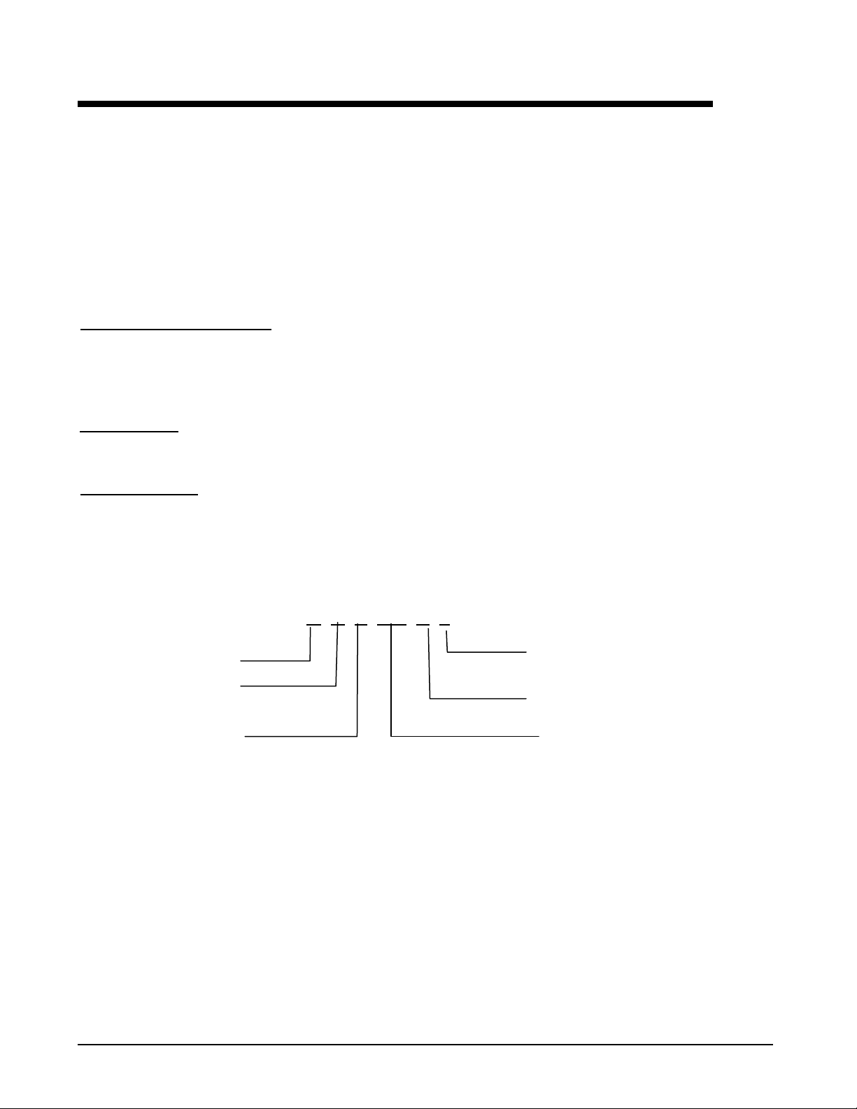
NOMENCLATURE
A C Z 010 B S
Air-cooled
C = Condensing Unit
G = Packaged Chiller
Scroll Compressor Nominal Capacity (Tons)
S = Standard Unit
M = Remote Evaporator
Vintage
Catalog 616
3
Page 4

Features and Benefits
ACZ-AGZ, Single Circuit Units
Great values also come in small packages. The ACZ and AGZ units have a single refrigerant circuit with
capacities from 10 to over 34 tons. Customer benefits include high efficiency operation, low sound levels,
efficient and reliable scroll compressor technology, and MicroTech II controls.
High Efficiency Operation
These units operate at high efficiency with IPLVs up to 14.6 EER. Through the use of tandem scroll
compressors and the latest control technology, excellent part load performance occurs. With a single
compressor running, the entire unit’s condenser surface is utilized, lowering condenser pressure and
reducing power input.
Quiet Operation
ACZ and AGZ units have low sound ratings through the use of scroll compressors. These compressors are
housed in a sheet metal enclosure to further reduce the levels. All units have a sound power rating of 90
dBA or less. For additional sound attenuation, optional acoustic blankets are also available. See page 25
re information regarding our low sound levels.
o
for m
Superior Control with MicroTech II
They have the MicroTech II controller providing control strategies expected of much larger units.
Building Automation System Integration
The MicroTech II controller allows for easy BAS integration through our Open Choice feature using
ONMARK, BACnet or Modbus communications. This is another advanced feature typical of larger units.
L
Figure 1, Model ACZ 033, 30-ton Condensing Unit
4 Catalog 616
Page 5

Design Features
The Daikin air-cooled, scroll compressor units are a product of Daikin’s commitment to offer
quiet, reliable, energy efficient equipment. These units incorporate high quality compressors,
state-of-the-art coil design, and innovative packaging.
Construction
Factory assembled and mounted on a heavy-gauge steel channel base. The base rails, supports and cabinetry are
powder-coat painted. The base distributes the unit weight for roof loading. Varied and convenient installation is
possible by virtue of the unit's small footprint.
Compressors
Copeland’s Compliant Scroll tandem compressors are used. These rugged hermetic compressors are
constructed with an integral cast iron frame, cast iron scrolls, three Teflon impregnated bearings, and three oil
filtration devices for each compressor.
Using Copeland's Compliant Scroll tandem compressors provides two steps of capacity modulation. One
compressor can run alone, depending on the load of the system, utilizing the entire unit’s condenser surface,
which results in excellent part-load efficiency. The refrigerant circuit has specially designed oil and gas
equalization lines to control oil migration.
The design also offers radial and axial compliance (no tip seals), a large internal volume for liquid handling, a
removable suction screen, and a rotary dirt trap and oil screen. In addition, the compressor is self-compensating
for wear, handles liquid and debris, and inherently yields the highest efficiency for its class.
This well protected compressor includes a solid-state motor protection module, 4 individual motor-winding
sensors, a patented internal discharge temperature probe, and a patented shutdown feature that prevents reverse
rotation. An internal discharge check valve helps prevent shutdown noise and comes standard with high and
low pressure taps with Schrader valves, a sight glass, an oil level adjustment valve, and an off cycle crankcase
heater.
Units are available in 60 Hertz electrical voltage configurations from 208 to 575 volt operating at 3500 rpm.
Condenser Coils
Condenser coils have internally enhanced seamless copper tubes arranged in a staggered row pattern. The
coils are mechanically expanded into Daikin lanced and rippled aluminum fins with full fin collars. A variety
of optional coil material and coatings are available for corrosive atmospheres. The external condenser coils are
fitted with a protective wire mesh guard as standard equipment.
Condenser Fans and Motors
Multiple direct-drive, dynamically balanced, propeller fans operate in formed venturi openings at low tip
speeds for maximum efficiency and minimum noise and vibration. A heavy-gauge vinyl-coated fan guard
protects each fan.
Each condenser fan motor is heavy-duty, 3-phase, Totally Enclosed Air Over (TEAO) with permanently
lubricated ball bearings and inherent overload protection. SpeedTrol option includes a single-phase motor with
fan speed control on the lead fan.
Evaporator
Stainless steel, brazed plate evaporators are used on the AGZ units. They have counter-flow operation and very
high efficiencies.
Catalog 616
5
Page 6
Electrical Control Center
Operating and equipment protection controls and motor starting components are separately housed in a
centrally located, weather-resistant control panel with hinged and tool-locked doors. In addition to the
MicroTech II controller described in the next sections, the following components are housed in the panel:
Standard single-point, terminal block connection
Control, input, and output terminal block
Control transformer
Phase voltage monitor with under/over voltage and phase reversal protection
Fan contactors with short circuit protective devices
The standard FanTrol head pressure control system controls refrigerant discharge pressure by fan
staging. The FanTrol system cycles condenser fans based on discharge pressure and outdoor temperature and
is designed for operation down to 35°F (1.7°C).
Optional SpeedTrol™ control using both fan cycling and fan speed control on the lead fan per circuit and
allows operation to 0°F (-18°C) outdoor temperature.
Mechanical high pressure cutout
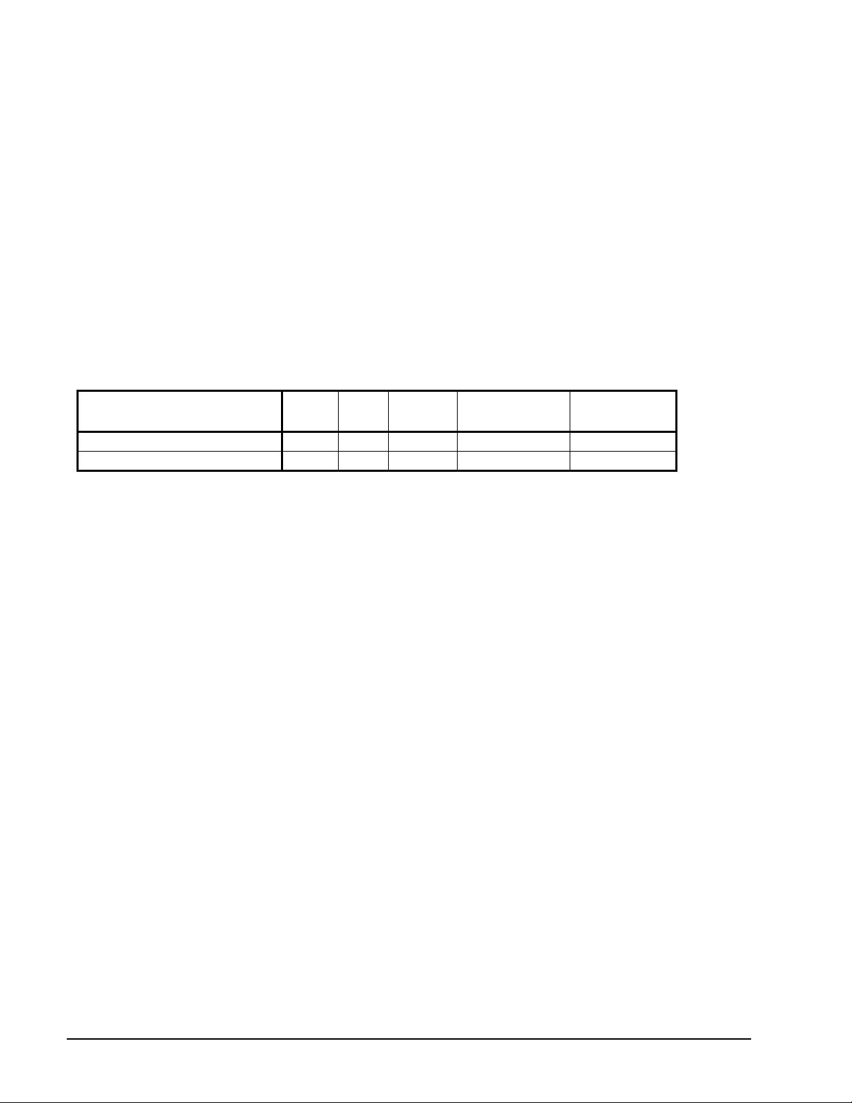
Power connections are per following table:
Power Connection
ACZ 010-039, Single-Point Connection Std. Opt Not Avail. Opt. Opt.
AGZ 010-034 Single Point Connection Std. Opt Not Avail. Opt. Opt.
Power
Block
Disc.
Swt.
Comp.
Circuit
Breakers
Definitions:
1. Power Block: An electrical device to directly accept field wiring without any disconnecting means.
2. Disconnect Switch: A molded case switch that accepts field wiring and disconnects main power to the
entire unit or each main power supply if the multi-point power supply option is selected. This option does
not provide overcurrent protection.
3. Unit Circuit Breaker with High Interrupting Capacity: A molded case circuit breaker acting as the
main disconnect switch with short circuit current rating (formally known as “withstand”). One circuit
breaker is provided. The circuit breaker provides overcurrent protection for the power supply.
4. Control Panel High Short Circuit Current Rating: (Previously known as “withstand rating”). The
entire control panel is designed for short circuit current rating. In the event of a short circuit, the damage
is contained within the control panel enclosure.
High Interr
Disconnect Switch
Current Rating
High Short Circuit
Current Rating w/
Disconnect Switch
Control System
The MicroTech II
systems available today on this class of equipment. This powerful, user-friendly control system provides
the flexibility and performance needed for either stand-alone unit operation or the controller can be easily
tied into your building automation system of choice using Daikin’s exclusive Open Choices feature that
allows you to choose from open standard protocols such as BACnet, Modbus, and LonTalk to
communicate easily with the building automation system that best meets your facility requirements. These
optional communications modules are available factory-installed or can be easily field installed.
MicroTech II’s state-of-the-art design will not only permit the unit to run more efficiently, but will also
simplify troubleshooting if a system failure occurs. Every MicroTech II controller is programmed and tested
prior to shipment.
Operator-friendly
The MicroTech II control menu structure is separated into four distinct categories that provide the operator or
service technician with a full description of current unit status, control parameters, and alarms. Security
protection helps prevent unauthorized changing of the setpoints and control parameters.
MicroTech II continuously performs self-diagnostic checks, pressures and protection devices, monitoring
system temperatures, and it will automatically shutdown a compressor, or the entire unit, if a fault occurs. The
6 Catalog 616
advanced DDC unit controller surpasses all other microprocessor-based unit control
Page 7

cause of the shutdown will be retained in memory and can be easily displayed in English or metric units for
operator review.
The MicroTech II unit controller can also retain and display the time that the fault occurred and the operating
conditions that were present at the time of the fault, an extremely useful feature for troubleshooting. In
addition to displaying alarm diagnostics, the MicroTech II controller also provides the operator with a
warning of pre-alarm conditions. Alarm notification data can also be passed on to your BAS through an
optional communications module.
Staging
On ACZ condensing units, temperature control for the system is provided by the installer through a field
supplied temperature controller. The field-supplied staging signals are provided to the MicroTech II controller
which correspondingly activates and deactivates the scroll compressors. The temperature controller is
required to close normally-open 24 volt contacts on a demand for cooling. These closure signals are field
wired to the terminal strip (TB2) in the condensing unit. Refer to the typical field wiring diagram on page 34
wo control stages are required:
for details.
Lead/lag is automatic and switched based on operating hours and compressor starts.
T
Equipment Protection
The unit is protected in two ways: (1) by alarms that shut the unit down and require manual reset to restore
unit operation and (2) by limit alarms that reduce unit operation in response to some out-of-limit condition.
Shut down alarms can activate a remote alarm signal. Limit alarms activate a signal on the controller.
Shutdown Alarms
High condenser pressure
No chilled water flow
Motor protection sy
Phase voltage protection (Optional on ACZ-B and
Outside am
Sensor failures
Limit Ala
rms
Condenser pressure stage down, unloads unit at high dischar
Low am
Low evaporator pressure hold, holds stage #1 until pressure rises
Low evaporator pressure unload, shuts off stage #2
bient temp
bient lockout, shuts off unit at low ambient temp
stem
AGZ-B)
erature
ge pressures
eratures
Unit Enable Selection
Enables unit operation from either local keypad, digital input, or BAS
Unit Mode Selection
Selects standard cooling, or test operation mode
Digital Inputs
Unit off switch
Remote start/stop
Flow switch
Digital Outputs
Shutdown alarm; field wired, activates on an alarm condition, off when alarm is cleared
Evaporator pump or air handler fan motor; field wired, starts when unit is set to start
Catalog 616
7
Page 8
Condenser fan control
The MicroTech II controller provides control of condenser fans. The controller stages condenser fans based
on discharge pressure.
Building Automation System (BAS) Interface
The following BAS standard protocols are supported through Daikin’s Open Choices option:
BACnet/IP
BACnet MS/TP
BACnet Ethernet
L
onTalk
Modbus
The following functions are generally available depending on the application and protocol in use:
Enable/disable operation
Select operating mode
Set the network limit variable
Read all digital and analog inputs and outputs
Read operating mode and status
Send a description of each alarm when it occurs
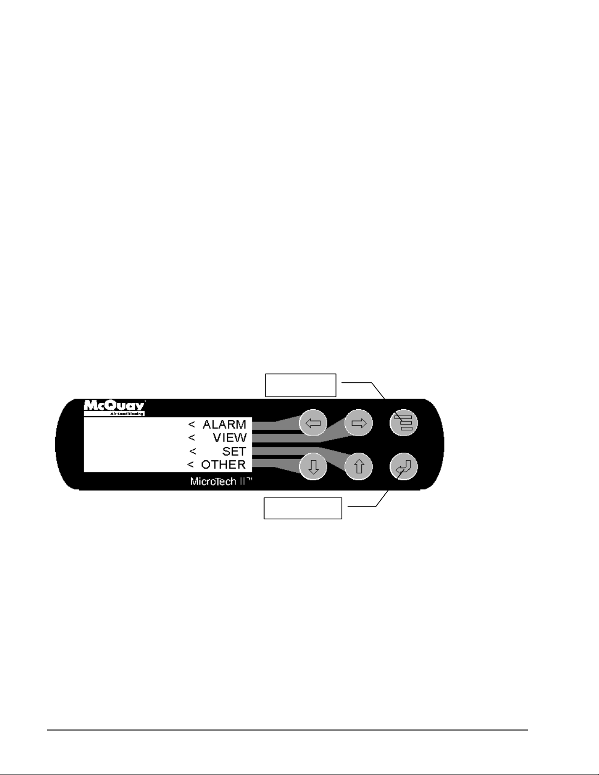
Keypad/Display
A 4-line by-20 character/line liquid crystal display and 6-key keypad is mounted on the unit controller. Its
layout is shown in
1Figure 2.
Figure 2, MicroTech II
Keypad
Menu Button
"Enter" Button
The four arrow buttons (UP, DOWN, LEFT, RIGHT) have three modes of use.
Scroll between data screens as indicated by the arrows (default mode).
Select a specific data screen in a hierarchical fashion using dynamic labels on the right side of the display
(this mode is entered by pressing the MENU button).
Change field values in edit mode.
8 Catalog 616
Page 9
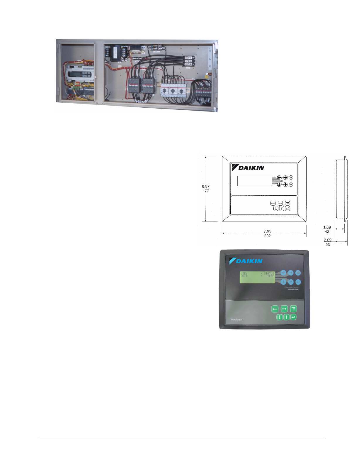
Figure 3, ACZ/AGZ-B Control Panel
Optional Remote Interface Panel
The ACZ/AGZ units can be individually equipped with a
remote user interface. It provides convenient access to
unit diagnostics and control adjustments, remote from
the condensing unit panel. A separate panel is required
for each chiller on a job site.
Each remote user interface is similar to its unit-mounted
counterpart and offers the same functionality, including:
Touch-sensitive keypad with a 4 line by 20-character
display format
Digital display of messages in English language
All operating conditions, system alarms, control
parameters
Figure 4, Remote Interface Panel Dimensions
Features
Can be wired up to 1,640 feet (500 m
unit for flexibility in placing each rem
eters) from the
ote user interface
within your building.
The main control is isolated from the remote user interface
wiring so that wiring problems are less likely to damage the
unit user interface.
Can be placed on a desk or surface or recessed wall mounted.
Benefits
Allows y
ou to access the user interface for each unit from
one location, inside the building.
Users need to learn one format because the rem
ote user
interface is identical to the unit-mounted version.
No additional field commissioning is required for the remote user interface.
Can be retrofit after unit installation.
All the BAS communications options are still available with the remote interface panel.
Cable and Wiring Recommendations
No more than 1,640 feet (500 m
eters) of wiring can be used to connect the remote user interface to the unit.
Power: AWG 22 twisted pair cable.
Communications: Belden 9841 or equal AWG 22 twisted pair.
A separate small communication terminal board is used at the unit and at the remote panel.
Catalog 616
9
Page 10
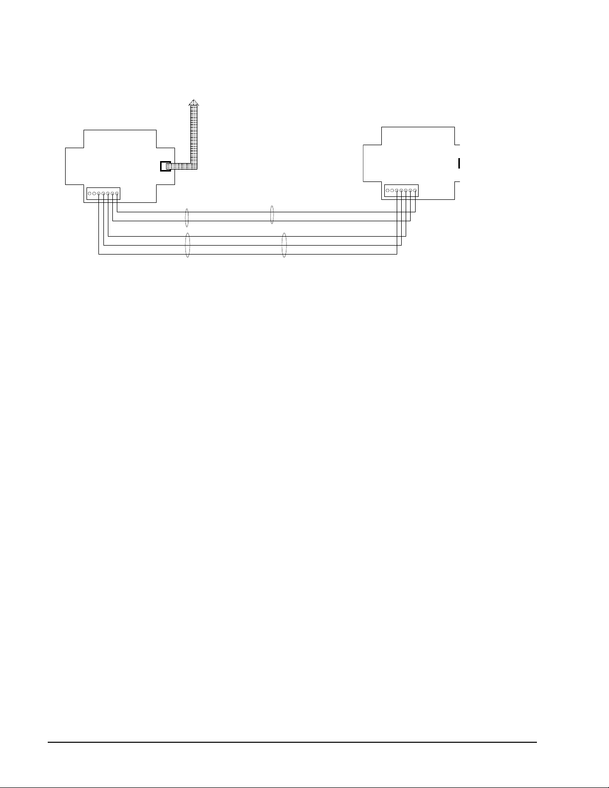
Figure 5, Remote User Interface Wiring Diagram
p
D
A
r
pLAN
cable
Chiller Terminal Board
0 1 2 3 4 5 6
sc
pLAN phone style
cable to J10 of
Display Terminal Board
chiller Unit control
Note:
Maximum distance between terminal
blocks is 1640 feet (500 m)
A
0 1 2 3 4 5 6
sc
Power is supplied through
30 Vdc +
Power Common
RX+/Tx+
Rx-/Tx-
Shield
AWG22 twist ed pair cable
Communications cable is
Belden 9841 or equivalent
WG22 twisted pai
10 Catalog 616
Page 11
ACZ Condensing Unit Performance
Selection Procedure
ACZ condensing units are selected in conjunction with some kind of evaporator equipment. The ACZ ratings
are based on saturated suction temperature at the compressor inlet and on ambient air dry-bulb temperature. For
a system selection, the ACZ condensing unit is usually selected first, and then the line loss added to the
condensing unit saturated suction temperature to determine the saturated evaporating temperature. This
temperature is then used for the selection of the evaporator, whether it is a DX cooling coil or water heat
exchanger. The pipe size can be determined from procedures and data in the Refrigerant Piping Section. For
selection purposes, the tubing size is based on a pressure equivalent of a two-degree F line loss (equal to about
3-psi pressure drop).
uired job capacity by
The correction for altitude found in Table 1 is applied, if applicable, by dividing the re
the correction factor to ascertain the necessary unit capacity in the Capacity Tables.
R-407C NOTE: R-407C is an azeotrope and as such has a glide characteristic. An evaporator mid-point
temperature will be about four-degrees higher than the dew point temperature. For example, an R-22 evaporator
selected at a 40F evaporating temperature would be comparable to 44F with R-407C.
Selection example, Inch-Pound units
Given:
200 Mbh job requirement 95°F ambient temperature
40F saturated suction temperature 2,000 foot altitude
R-22
1. To select the correct size unit, correct for altitude by dividing the required capacity by
factor found in T
200 Mbh required / 0.986 factor = 202 Mbh corrected requirem
2. From Table 2 on the following page, an ACZ 020 at th
unit power input of 20.0 kW
3.
Correct for altitude:
Capacity: 202.5 Mbh x 0.986 = 200 Mbh
Power: 20.0 kW x 1.009 = 20.2 kW
EER: 10.1 EER x 0.986/1.009 = 9.9 EER
4. An evaporator would be selected at 42F saturated evaporating temperature.
able 1.
ent.
e given conditions will produce 202.5 Mbh with a
and a unit EER of 10.1.
q
the correction
Selection example-SI units
Use the same procedure as for Inch-Pounds but use SI tables and units.
Application Adjustment Factors
Altitude Correction Factors
Performance tables are based at sea level. Elevations other than sea level affect the performance of the unit.
The decreased air density will reduce condenser capacity, consequently reducing the unit's performance.
Table 1, Altitude Correction Factors
Altitude Capacity Power
Sea Level 1.000 1.000
2000 ft (610 m) 0.986 1.009
4000 ft (1220) m 0.973 1.021
6000 ft (1830) m 0.959 1.031
Catalog 616
11
Page 12
ACZ Performance Data
Table 2, R-407C, I-P Units, 60 Hz
Suction
ACZ
Dewpoint
Unit
Size
010
013
016
020
025
028
033
039
NOTES:
1. Ratings based on R-407C, and sea level altitude.
2.
3. KWi and EER are for the entire unit, including compressors, fan motors and control power.
4. Rated in accordance with ARI Standard 365-2002.
Temp
(F)
30 1.8 85.6 8.2 10.4 84.4 8.6 9.9 79.7 9.2 8.7 74.9 10.0 7.5 70.2 10.8 6.5
35 1.8 95.1 8.3 11.4 92.8 8.7 10.7 88.0 9.4 9.4 83.2 10.1 8.2 77.3 10.9 7.1
40 1.8 104.7 8.6 12.2 102.3 8.9 11.5 96.3 9.5 10.2 91.6 10.3 8.9 85.6 11.1 7.7
45 1.8 114.2 8.7 13.2 111.8 9.0 12.5
50 1.8 124.9 8.9 14.1 122.5 9.2 13.4 116.5 9.9 11.8 109.4 10.6 10.3 103.5 11.5 9.0
55 1.8 135.6 9.2 14.8 133.2 9.5 14.0 126.1 10.1 12.5 120.1 10.9 11.0 113.0 11.7 9.6
30 1.8 112.4 11.1 10.2 108.8 11.6 9.4 103.9 12.5 8.3 97.9 13.7 7.1 91.9 15.0 6.1
35 1.8 125.7 11.4 11.1 122.1 11.8 10.3 116.0 12.9 9.0 110.0 14.0 7.8 102.7 15.3 6.7
40 1.8 140.2 11.6 12.1 136.6 12.1 11.3 130.5 13.1 10.0 123.3 14.2 8.7 116.0 15.6 7.4
45 1.8 155.9 12.0 13.0 152.3 12.4 12.2
50 1.8 171.6 12.3 13.9 168.0 12.8 13.2 159.5 13.8 11.5 152.3 15.0 10.2 142.6 16.3 8.8
55 1.8 188.6 12.6 14.9 184.9 13.2 14.0 176.5 14.1 12.5 166.8 15.3 10.9 157.1 16.7 9.4
30 1.8 154.7 16.1 9.6 150.9 16.8 9.0 143.4 18.3 7.8 136.0 20.1 6.8 128.5 21.9 5.9
35 1.8 170.9 16.4 10.4 165.9 17.1 9.7 158.4 18.5 8.5 149.7 20.3 7.4 140.9 22.2 6.3
40 1.8 187.1 16.7 11.2 183.3 17.4 10.6 174.6 18.9 9.2 165.9 20.7 8.0 155.9 22.6 6.9
45 1.8 205.8 17.0 12.1 200.8 17.7 11.3
50 1.8 225.8 17.4 13.0 220.8 18.1 12.2 209.5 19.6 10.7 199.6 21.4 9.3 187.1 23.3 8.0
55 1.8 247.0 17.8 13.8 242.0 18.5 13.0 229.5 20.1 11.4 218.3 21.9 10.0 205.8 23.7 8.7
30 1.8 178.1 17.3 10.3 174.5 18.0 9.7 165.0 19.7 8.4 155.4 21.5 7.2 145.8 23.4 6.2
35 1.8 196.0 17.7 11.1 191.3 18.4 10.4 181.7 20.1 9.0 170.9 21.9 7.8 160.2 23.9 6.7
40 1.8 215.2 18.1 11.9 210.4 18.8 11.2 198.4 20.6 9.6 187.7 22.5 8.4 175.7 24.4 7.2
45 1.8 235.5 18.5 12.7 229.5 19.4 11.9
50 1.8 255.8 19.1 13.4 249.8 19.9 12.6 236.7 21.5 11.0 223.5 23.4 9.6 210.4 25.4 8.3
55 1.8 278.5 19.6 14.2 271.4 20.4 13.3 257.0 22.0 11.7 242.7 24.0 10.1 228.3 26.1 8.8
30 2.7 238.0 23.4 10.2 233.1 24.3 9.6 220.9 26.5 8.3 207.4 28.7 7.2 193.9 31.3 6.2
35 2.7 262.6 23.9 11.0 256.5 24.9 10.3 243.0 27.0 9.0 229.5 29.4 7.8 214.7 32.0 6.7
40 2.7 288.4 24.4 11.8 281.0 25.5 11.0 267.5 27.7 9.7 251.5 30.0 8.4 235.6 32.6 7.2
45 2.7 315.4 25.1 12.6 308.0 26.1 11.8
50 2.7 344.8 25.8 13.3 336.2 26.8 12.5 319.0 29.0 11.0 300.6 31.3 9.6 282.2 34.0 8.3
55 2.7 374.3 26.5 14.1 365.7 27.6 13.3 347.3 29.7 11.7 327.6 32.1 10.2 308.0 34.9 8.8
30 2.7 261.5 26.9 9.7 255.3 28.0 9.1 241.8 30.3 8.0 227.0 33.0 6.9 212.2 35.9 5.9
35 2.7 288.6 27.6 10.5 281.2 28.7 9.8 266.4 31.1 8.6 250.4 33.8 7.4 234.4 36.6 6.4
40 2.7 315.8 28.3 11.1 308.4 29.4 10.5 292.3 31.9 9.2 275.1 34.5 8.0 257.8 37.5 6.9
45 2.7 345.4 29.1 11.9 336.7 30.2 11.1
50 2.7 376.2 30.0 12.5 367.6 31.1 11.8 349.1 33.5 10.4 329.3 36.3 9.1 308.4 39.3 7.8
55 2.7 409.5 30.9 13.3 399.7 32.0 12.5 378.7 34.4 11.0 357.7 37.2 9.6 335.5 40.3 8.3
30 2.7 307.8 30.9 10.0 300.8 32.3 9.3 285.7 35.4 8.1 269.5 38.8 7.0 253.2 42.3 6.0
35 2.7 339.2 31.8 10.7 331.0 33.1 10.0 313.6 36.2 8.7 296.2 39.6 7.5 278.8 43.3 6.4
40 2.7 371.7 32.6 11.4 362.4 34.0 10.7 343.8 37.2 9.2 325.2 40.5 8.0 305.5 44.3 6.9
45 2.7 405.4 33.6 12.1 396.1 35.0 11.3
50 2.7 441.4 34.6 12.8 430.9 36.0 12.0 410.0 39.2 10.5 387.9 42.7 9.1 364.7 46.5 7.8
55 2.7 479.7 35.7 13.5 468.1 37.1 12.6 444.8 40.3 11.0 420.5 43.8 9.6 394.9 47.7 8.3
30 2.7 382.2 42.1 9.1 372.8 43.8 8.5 353.0 47.6 7.4 330.9 51.6 6.4 306.4 55.8 5.5
35 2.7 420.6 43.2 9.7 410.1 45.0 9.1 388.0 48.9 7.9 363.5 53.1 6.9 337.9 57.4 5.9
40 2.7 460.2 44.6 10.3 448.6 46.4 9.7 424.1 50.3 8.4 398.5 54.5 7.3 370.5 59.0 6.3
45 2.7 501.0 46.0 10.9 488.2 47.9 10.2
50 2.7 544.1 47.6 11.4 531.3 49.4 10.8 502.2 53.4 9.4 473.0 57.8 8.2 440.4 62.5 7.1
55 2.7 590.7 49.2 12.0 575.6 51.1 11.3 544.1 55.1 9.9 511.5 59.6 8.6 477.7 64.3 7.4
Interpolation is allowed; extrapolation is not permitted. Consult the local Daikin sales office for performance outside the cataloged
ratings.
Fan &
Control
Power
(kW)
75 85 95 105 115
Unit
PWR
Unit
Unit
Mbh
kWi
EER
PWR
Mbh
Ambient Air Temperature (F)
Unit
Unit
kWi
EER
PWR
Mbh
kWi
105.8 9.7 10.9
145.0 13.4 10.8
192.1 19.3 10.0
217.6 21.0 10.4
292.0 28.2 10.4
319.5 32.6 9.8
376.3 38.1 9.9
462.6 51.8 8.9
Unit
Unit
PWR
Unit
EER
Mbh
kWi
99.9 10.4 9.6 93.9 11.3 8.3
136.6 14.6 9.4 129.3 15.9 8.1
182.1 21.0 8.7 170.9 22.9 7.5
205.6 22.9 9.0 192.5 24.9 7.7
276.1 30.7 9.0 258.9 33.4 7.8
302.2 35.4 8.5 282.5 38.4 7.4
355.4 41.6 8.5 334.5 45.4 7.4
434.6 56.2 7.7 405.5 60.6 6.7
EER
Unit
Mbh
PWR
kWi
Unit
EER
12 Catalog 616
Page 13
Table 3, R-407C, SI, 60 Hz
ACZ
Unit
Size
010
013
016
020
025
028
033
039
NOTES:
1.
2.
3.
Suction
Dewpoint
Temp
(C)
-1
11
13
-1
11
13
-1
11
13
-1
11
13
-1
11
13
-1
11
13
-1
11
13
-1
11
13
Fan &
Control
Power
(kW)
2
5
8
2
5
8
2
5
8
2
5
8
2
5
8
2
5
8
2
5
8
2
5
8
Ratings based on R-407C and sea level altitude.
Interpolation is allowed; extrapolation is not permitted. Consult the local Daikin sales office for performance outside the
cataloged ratings.
KWi and COP are for the entire unit, including compressors, fan motors and control power.
Unit
kW
1.8 25.1 7.6 3.3 23.9 8.3 2.9 22.7 8.8 2.6 21.3 9.6 2.2 19.8 10.5 1.9
1.8 27.9 7.8 3.6 26.6 8.4 3.2 25.3 9.0 2.8 23.8 9.8 2.4 22.2 10.7 2.1
1.8 30.9 7.9 3.9 29.5 8.6 3.4 28.0 9.2 3.0 26.4 10.0 2.6 24.7 10.9 2.3
1.8 34.1 8.1 4.2 32.5 8.8 3.7
1.8 37.5 8.4 4.5 35.7 9.0 4.0 34.1 9.6 3.6 32.2 10.4 3.1 30.2 11.3 2.7
1.8 39.9 8.5 4.7 38.0 9.1 4.2 36.3 9.7 3.7 34.2 10.6 3.2 32.1 11.5 2.8
1.8 32.8 10.2 3.2 31.1 11.2 2.8 29.7 12.1 2.5 27.9 13.3 2.1 26.0 14.7 1.8
1.8 37.1 10.5 3.5 35.3 11.4 3.1 33.7 12.4 2.7 31.7 13.6 2.3 29.5 15.0 2.0
1.8 41.7 10.8 3.8 39.7 11.8 3.4 37.9 12.7 3.0 35.8 13.9 2.6 33.4 15.3 2.2
1.8 46.6 11.2 4.1 44.4 12.2 3.6
1.8 51.8 11.6 4.5 49.4 12.5 4.0 47.2 13.4 3.5 44.6 14.6 3.0 41.8 16.0 2.6
1.8 55.3 11.9 4.7 52.8 12.8 4.1 50.5 13.6 3.7 47.7 14.8 3.2 44.8 16.3 2.7
1.8 45.4 14.9 3.0 43.0 16.4 2.6 41.2 17.6 2.3 38.8 19.5 2.0 36.3 21.4 1.7
1.8 50.5 15.3 3.3 47.9 16.6 2.9 45.8 18.0 2.5 43.2 19.8 2.2 40.5 21.7 1.9
1.8 55.9 15.6 3.6 53.2 17.0 3.1 50.8 18.3 2.8 48.0 20.1 2.4 44.9 22.1 2.0
1.8 61.9 15.9 3.9 58.7 17.3 3.4
1.8 68.3 16.3 4.2 64.9 17.8 3.7 62.1 19.1 3.2 58.6 20.9 2.8 54.9 23.0 2.4
1.8 72.7 16.6 4.4 69.2 18.1 3.8 66.2 19.3 3.4 62.5 21.3 2.9 58.4 23.2 2.5
1.8 52.5 15.9 3.3 49.7 17.5 2.8 47.3 18.9 2.5 44.3 20.8 2.1 41.3 22.8 1.8
1.8 58.1 16.3 3.6 55.1 17.9 3.1 52.5 19.4 2.7 49.3 21.3 2.3 46.0 23.3 2.0
1.8 64.2 16.8 3.8 60.8 18.4 3.3 57.9 19.9 2.9 54.4 21.8 2.5 50.8 23.8 2.1
1.8 70.6 17.3 4.1 66.9 18.9 3.5
1.8 77.4 17.8 4.3 73.3 19.4 3.8 69.9 20.9 3.3 65.6 22.8 2.9 61.3 25.0 2.4
1.8 82.0 18.1 4.5 77.8 19.8 3.9 74.1 21.3 3.5 69.6 23.2 3.0 65.0 25.4 2.6
2.7 69.9 21.7 3.2 66.4 23.6 2.8 63.3 25.5 2.5 59.3 27.9 2.1 55.0 30.5 1.8
2.7 77.6 22.2 3.5 73.7 24.2 3.0 70.2 26.1 2.7 65.9 28.5 2.3 61.3 31.3 2.0
2.7 85.9 22.8 3.8 81.5 24.9 3.3 77.7 26.7 2.9 72.9 29.2 2.5 68.0 32.0 2.1
2.7 94.6 23.5 4.0 89.8 25.5 3.5
2.7 103.7 24.2 4.3 98.4 26.2 3.8 94.0 28.1 3.3 88.3 30.6 2.9 82.4 33.4 2.5
2.7 110.1 24.8 4.4 104.5 26.7 3.9 99.6 28.6 3.5 93.7 31.2 3.0 87.5 33.9 2.6
2.7 76.8 24.9 3.1 72.9 27.2 2.7 69.4 29.3 2.4 64.8 32.0 2.0 59.9 35.0 1.7
2.7 85.1 25.7 3.3 80.8 27.9 2.9 77.0 30.1 2.6 72.1 32.8 2.2 66.8 35.9 1.9
2.7 94.0 26.4 3.6 89.3 28.7 3.1 85.1 30.8 2.8 79.8 33.7 2.4 74.1 36.8 2.0
2.7 103.4 27.3 3.8 98.2 29.5 3.3
2.7 113.5 28.2 4.0 107.7 30.5 3.5 102.6 32.6 3.1 96.3 35.5 2.7 89.7 38.7 2.3
2.7 120.3 28.9 4.2 114.1 31.1 3.7 108.8 33.2 3.3 102.1 36.1 2.8 95.2 39.3 2.4
2.7 90.5 28.5 3.2 85.8 31.4 2.7 81.9 34.1 2.4 77.1 37.5 2.1 72.0 41.2 1.7
2.7 100.2 29.4 3.4 95.2 32.3 2.9 90.8 34.9 2.6 85.5 38.4 2.2 79.9 42.2 1.9
2.7 110.6 30.2 3.7 105.1 33.2 3.2 100.3 35.9 2.8 94.3 39.5 2.4 88.2 43.3 2.0
2.7 121.5 31.2 3.9 115.5 34.2 3.4
2.7 133.1 32.3 4.1 126.4 35.2 3.6 120.8 38.1 3.2 113.6 41.7 2.7 106.2 45.7 2.3
2.7 141.0 33.1 4.3 134.0 36.1 3.7 128.0 38.8 3.3 120.4 42.5 2.8 112.6 46.6 2.4
2.7 112.4 38.9 2.9 106.7 42.5 2.5 101.4 45.8 2.2 94.5 50.0 1.9 86.9 54.3 1.6
2.7 124.4 40.1 3.1 117.9 43.8 2.7 112.2 47.1 2.4 104.8 51.4 2.0 96.6 55.9 1.7
2.7 137.0 41.5 3.3 129.9 45.3 2.9 123.6 48.7 2.5 115.5 53.1 2.2 106.7 57.7 1.8
2.7 150.4 42.9 3.5 142.5 46.8 3.0
2.7 164.4 44.6 3.7 155.7 48.5 3.2 148.1 52.0 2.8 138.5 56.5 2.4 128.4 61.3 2.1
2.7 174.0 45.7 3.8 164.8 49.6 3.3 156.7 53.1 2.9 146.6 57.7 2.5 135.9 62.7 2.2
Ambient Air Temperature (F)
24C 30C 35C 41C 47C
PWR
Unit
Unit
PWR
Unit
Unit
PWR
Unit
Unit
PWR
Unit
Unit
kWi
COP
kW
kWi
COP
kW
31.0 9.4 3.1
42.5 13.0 3.1
56.3 18.7 2.9
63.8 20.4 3.0
85.6 27.3 3.0
93.6 31.7 2.8
110.3 36.9 2.8
135.6 50.2 2.6
kWi
COP
kW
kWi
COP
29.2 10.2 2.9 27.4 11.1 2.5
40.1 14.2 2.8 37.4 15.6 2.4
53.2 20.5 2.6 49.7 22.5 2.2
59.9 22.2 2.7 55.9 24.4 2.3
80.4 29.9 2.7 75.0 32.7 2.3
87.8 34.5 2.5 81.7 37.7 2.2
103.8 40.5 2.6 97.0 44.5 2.2
126.8 54.7 2.3 117.4 59.5 2.0
kW
PWR
kWi
Unit
COP
Catalog 616
13
Page 14

ACZ Part Load Data
Table 4, IP Units, 60Hz
R-407C Part Load Data
Suct
ACZ
Unit
% Load
Size
100 95.0 45.0 105.8 9.7 10.9
010B
013B
016B
020B
025B
028B
033B
039B
NOTES:
1. Certified according to ARI Standard 365-2002.
2. The 100 percent load, 95F, performance data is for information only and is not a factor in calculating a condensing unit IPLV
100 80.0 50.0 123.7 9.0 13.8
100 95.0 45.0 145.0 13.4 10.8
100 80.0 50.0 169.8 12.5 13.6
100 95.0 45.0 192.1 19.3 10.0
100 80.0 50.0 223.3 17.7 12.6
100 95.0 45.0 217.6 21.0 10.4
100 80.0 50.0 252.8 19.4 13.0
100 95.0 45.0 292.0 28.2 10.4
100 80.0 50.0 340.5 26.4 12.9
100 95.0 45.0 319.5 32.6 9.8
100 80.0 50.0 371.9 30.5 12.2
100 95.0 45.0 376.3 38.1 9.9
100 80.0 50.0 436.2 35.2 12.4
100 95.0 45.0 462.6 51.8 8.9
100 80.0 50.0 537.7 48.4 11.1
Outdoor
Air
Temp
53 80.0 50.0 63 4.2 12.5
53 80.0 50.0 87 6.5 13.3
53 80.0 50.0 116 8.6 13.4
53 80.0 50.0 132 9.5 13.9
53 80.0 50.0 177 12.6 14.0
53 80.0 50.0 197 14.7 13.4
53 80.0 50.0 231 16.7 13.8
53 80.0 50.0 285 21.9 13.0
Dew
Point
Temp
(F)
Cap.
Mbh
Power
kWi
EER IPLV
13.0
13.4
13.0
13.5
13.6
13.0
13.2
12.2
.
14 Catalog 616
Page 15

AGZ Chiller Selection Procedure
F
Packaged Chiller, Model BS
Selection with Inch-Pound (I-P) units
Table 13 and Table 14 cover the range of leaving evaporator water temperatures and outside ambient
temperatures included under ARI Standard 550/590-2003. The tables are based on a 10 degree F (5.5 degree
C) temperature drop through the evaporator. Adjustment factors for applications having other than a 10 degree
5 degree C) drop can be found in Table 7. The minimum leaving chilled water temperature
F (5.
setpoint without glycol is 40°F (4C). For brine selections, see Table 5 through Table 6 for glycol
adjustment factors. Ratings are based on a 0.0001 ft2 x hr x F/Btu fouling factor in the evaporator at sea level
operation. For other fouling factors, different Delta-Ts, or altitude correction factors see Table 7. For
applications outside the catalog ratings contact your local Daikin sales representative.
Selection example
20 tons minimum requirement
95°F ambient temperature
48 gpm, 54F to 44°F chilled water
0.0001 evaporator fouling factor
1. From Table 13, an AGZ 020B at the given conditions will produce 21.5 tons with a unit kW
and a unit EER of 8.9.
2. Use the following formula to calculate any unknown elements.
tons
24
(water only)
gpm =
input of 29.0
3. Determine the evaporator pressure drop. Using Figure 7 on page, enter at 48 gpm and follow up to the
AGZ 020B line intersect. Read horizontally to obtain an evaporator pressure drop of 5.9 feet of water.
ote the allowable minimum and maximum flows.
N
Selection example using ethylene glycol
20 tons minimum requirement
95°F ambient air temperature
54°F - 44°F chilled water temperature
0.0001 evaporator fouling factor
Protect from freezing down to 0°F
1. From Table 5, select an ethylene glycol concentration of 40% to protect against freezing at 0°F.
2. At 40%
GPM = 1.132, pressure drop = 1.557
3. Select the AGZ 020B from Table 13 and correct with 40% ethylene glycol factors.
4. Correct capacity
5. Correct comp
6. Calculate chilled water flow:
Gly
ethylene gly
ressor kW = 0.992 X 29.0 kW = 28.8 kW
col flow (at 40% solution) = 1.132 X 48.0 gpm = 54.3 gpm
col, the adjustment factors are: Capacity =0.980, kW = 0.992,
= 0.980 X 21.5 tons = 21.1 tons
= capacity) corrected(at flowWater
tons
24×0.20
gpm 48 =
°10
F
Determine the evaporator pressure drop. Using Figure 7, enter at 20 gpm (water) and follow up to the AGZ
020B line intersect.
pressure drop for 40% solution = 1.557 x 5.9 feet = 9.2 feet for ethylene glycol.
Catalog 616
Read horizontally to obtain an evaporator pressure drop of 5.9 feet. Correct the
15
Page 16

Selection example, SI Units
The selection procedure for Metric units is identical to English except that metric data and tables are used.
Remote Evaporator, Model BM
Inch-Pound (I-P) Units
Since the AGZ-BM units always include a specific remote evaporator, packaged chiller ratings are used.
The ratings are based on leaving chilled water temperature and ambient air temperature with correction for
the effect of the interconnecting refrigerant piping.
Table 13 and Table 14 cover the range of leaving evaporator water temperatures and outside
ambient temperatures included under ARI 550/590-2003. The tables are based on a 10-degree F (5.5degree C) temperature drop through the evaporator. Adjustment factors for applications having other than
a 10-degree F (5.5-degree C) drop can be found in Table 7. The minimum leaving chilled water
temperature setpoint without glycol is 40°F (4C). For brine selections, see Table 5 or Table 6 for
glycol adjustment factors. Ratings are based on a 0.0001 ft2 x hr x F/Btu fouling factor in the evaporator
at sea level operation. For other fouling factors, different Delta-Ts, or altitude correction factors see Table
7. For applications outside the catalog ratings, contact your local Daikin sales representative.
The length and configuration of the field installed interconnecting refrigerant piping will affect the system
capacity. Derates based on equivalent length of line are given in Table 12.
The steps for selecting an AGZ-BM are as follows:
1. Add 3% to the required cooling capacity (to approximate the effect of the correction factors to be
determined) and make a preliminary unit selection from Table 13 and Table 14.
2. Divide the required capacity
Table 6, altitude, chilled water Delta T, or fouling factor from Table 7, and refrigerant piping derate
from Table 12 as explained in step 3 below.
3. Determ
summing the equivalent feet (from table 10) of
all the fittings (use a sketch of the piping
layout) and adding the sum of these fitting
losses to the actual linear feet of tubing. This
will equal the total equivalent feet. (To use the
equivalent feet table 10, start with the unit
suction connection size from table 13 and
correct if required.)
4. If the unit rated capacity in the tables is less
than the corrected required capacity, redo the
selection with the next larger unit. In most
cases the line size will be the unit connection
size. If the selection is satisfactory, correct the
power (if applicable) and determine water
pressure drop. Selection example
English Units
ine the suction line size by first
Given: 20 tons required capacity
95°F ambient temperature
Cool 48 gpm from 54F to 44°F
0.0001 evaporator fouling factor
2,000 foot altitude
by the appropriate capacity correction factors: glycols from Table 5 or
Figure 6, Sample Piping Layout
B
16 Catalog 616
Page 17

1. Add 3% to the required capacity for approximate derate: 20 x 1.03 = 20.6 tons. From Table 13 an AGZ020B at the given conditions will produce 21.5 tons with a unit kW
input of 29.0 and a unit EER of 8.9.
2. Determine derate factors:
Altitude correction from Ta
ble 7:
0.998 Capacity, 1.009 Power
3. Piping correction:
Assume 1 5/8” suction line based on line size in Tab le 11.
90 S
(3)
Plus actual linear feet 70 ft
tandard ells 3 x 4 ft =12 ft
Total Equivalent Feet 82 ft
This puts it between 1 5/8” and 2 1/8” line size.
Check Table 9 and find that 1 5/8” is maximum size for oil carry.
This m
eans that the 1 5/8 riser will be satisfactory
, but with a slightly higher pressure drop.
The capacity correction factor from Table 12 is between 0.97 and 0.98. Use 0.975.
of the
4. The corrected capacity
the 20 ton requirem
ent.
AGZ is: 21.5 tons x 0.998{altitude} x 0.98{piping} = 21.0 tons
5. Correct the unit power required: 29.0 kW x 1.009{altitude} = 29.3 kW
.
This satisfies
6. Calculate the unit EER based on the correct capacity and power:
EER = (21 tons x 12,000)/ (29.3 kW x 1,000) = 8.6
7. Determine the evaporator pressure drop. Enter the pressure drop curves, (Figure 7) at 48 gpm
and read up to
AGZ 020, read over to pressure drop of 5.9 ft.
Selection example, SI Units
The selection procedure for Metric units is identical to English except that metric data and tables are used.
Catalog 616
17
Page 18

Application Adjustment Factors
Ethylene and Propylene Glycol Factors
AGZ units can operate with a leaving chilled fluid temperature range of 20°F (-6°C) to 60°F (10°C). A
glycol solution is required when leaving chilled fluid temperature is below 40°F (4.6°C). The use of glycol
will reduce the performance of the unit depending on concentration.
Altitude Correction Factors
Performance tables are based at sea level. Elevations other than sea level affect the performance of the unit.
The decreased air density will reduce condenser capacity consequently reducing the unit's performance. For
performance at elevations other than sea level refer to Table 7.
Evaporator Temperature Drop Factors
Performance tables are based on a 10°F (5°C) temperature drop through the evaporator. Adjustment factors
for applications with temperature ranges from 6°F to 16°F (3.3°C to 8.9°C) are in Table 3. Temperature
drops outside this 6°F to 16°F (3.3°C to 8.9°C) range can affect the control system's capability to maintain
acceptable control and are not recommended.
The maximum water temperature that can be circulated through the evaporator in a non-operating mode is
100°F (37.8°C).
Table 5, Ethylene Glycol Factors
% E.G.
10
20
30
40
50
Freeze Point
°F °C
26 -3.3 0.998 0.998 1.036 1.097
18 -7.8 0.993 0.997 1.060 1.226
7 -13.9 0.987 0.995 1.092 1.369
-7 -21.7 0.980 0.992 1.132 1.557
-28 -33.3 0.973 0.991 1.182 1.791
Capacity Power Flow PD
T
able 6, Propylene Glycol Factors
% P.G.
10
20
30
40
50
NOTE: Ethylene and propylene glycol ratings are outside the scope of ARI Standard 550/590-2003 certification program.
18 Catalog 616
Freeze Point
°F °C
26 -3.3 0.995 0.997 1.016 1.100
19 -7.2 0.987 0.995 1.032 1.211
9 -12.8 0.978 0.992 1.057 1.380
-5 -20.6 0.964 0.987 1.092 1.703
-27 -32.8 0.952 0.983 1.140 2.251
Capacity Power Flow PD
Page 19

Fouling Factor
Performance tables are based on water with a fouling factor of
As fouling is increased, performance decreases. For performance at other than 0.0001 (0.0176) fouling factor
refer to Table 7. Foreign matter in the chilled water system will adversely af
the evaporator and could increase the pressure drop and reduce the water flow. Maintain proper water
treatment to provide optimum unit operation.
Table 7, Capacity and Power Derates
Chilled Water
Altitude
Sea
Level
2000 feet
4000 feet
6000 feet
Delta T
°F °C Cap. Power Cap. Power Cap. Power Cap. Power
6 3.3 0.978 0.993 0.975 0.991 0.963 0.987 0.940 0.980
8 4.4 0.989 0.996 0.986 0.994 0.973 0.990 0.950 0.983
10 5.6 1.000 1.000 0.996 0.999 0.984 0.994 0.961 0.987
12 6.7 1.009 1.003 1.005 1.001 0.993 0.997 0.969 0.990
14 7.7 1.018 1.004 1.014 1.003 1.002 0.999 0.978 0.991
16 8.9 1.025 1.007 1.021 1.006 1.009 1.001 0.985 0.994
6 3.3 0.977 1.001 0.973 1.000 0.961 0.996 0.938 0.989
8 4.4 0.987 1.006 0.984 1.004 0.971 1.000 0.948 0.993
10 5.6 0.998 1.009 0.995 1.007 0.982 1.003 0.959 0.996
12 6.7 1.007 1.011 1.004 1.010 0.991 1.006 0.967 0.998
14 7.7 1.014 1.014 1.011 1.013 0.998 1.009 0.974 1.001
16 8.9 1.022 1.016 1.018 1.014 1.005 1.010 0.981 1.003
6 3.3 0.973 1.011 0.970 1.010 0.957 1.006 0.935 0.998
8 4.4 0.984 1.014 0.980 1.013 0.968 1.009 0.945 1.001
10 5.6 0.995 1.019 0.991 1.017 0.979 1.013 0.955 1.005
12 6.7 1.004 1.021 1.000 1.020 0.987 1.016 0.964 1.008
14 7.7 1.011 1.024 1.007 1.023 0.994 1.018 0.971 1.011
16 8.9 1.018 1.027 1.014 1.026 1.002 1.021 0.978 1.014
6 3.3 0.969 1.021 0.966 1.020 0.954 1.016 0.931 1.008
8 4.4 0.980 1.026 0.977 1.024 0.964 1.020 0.942 1.013
10 5.6 0.989 1.029 0.986 1.027 0.973 1.023 0.950 1.015
12 6.7 0.998 1.033 0.995 1.031 0.982 1.027 0.959 1.020
14 7.7 1.007 1.036 1.004 1.034 0.991 1.030 0.967 1.022
16 8.9 1.014 1.037 1.011 1.036 0.998 1.031 0.974 1.024
0.0001 (0.0176) 0.00025 (0.044) 0.00075 (0.132) 0.00175 (0.308)
22
per ARI 550/590-2003.
)/0176.0(/0001.0
kWCmorBTUFhrft
fect the heat transfer capability of
Fouling Factor
Table 8, Equivalent Feet for Fittings
Fitting Type 7/8 1 1/8 1 3/8 1 5/8 2 1/8 2 5/8 3 1/8
Elbows
90 Standard
90 Long Radius
90 Street
45 Standard
45 Street
180 Bend
Tees
Full Size
Reducing
Valves
Globe Valve, Open
Gate Valve, Open
Angle Valve, Open
Catalog 616
2.0 2.6 3.3 4.0 5.0 6.0 7.5
1.4 1.7 2.3 2.6 3.3 4.1 5.0
3.2 4.1 5.6 6.3 8.2 10 12
0.9 1.3 1.7 2.1 2.6 3.2 4.0
1.5 2.1 3.0 3.4 4.5 5.2 6.4
3.2 4.1 5.6 6.3 8.2 10 12
1.4 1.7 2.3 2.6 3.3 4.1 5.0
2.0 2.6 3.3 4.0 5.0 6.0 7.5
22 29 38 43 55 69 84
0.9 1.0 1.5 1.8 2.3 2.8 3.2
9.0 12 15 18 24 29 35
19
Page 20

Table 9, Maximum Line Size (R-407C) For Oil Carry Up a Suction Riser
Unit Size
Line Size 1 1/8 1 3/8 1 5/8 1 5/8 1 5/8 2 1/8 2 1/8
AGZ
010
AGZ
013
AGZ
017
AGZ
020
AGZ
025
AGZ
029
AGZ
034
Table 10, Recommended Liquid Line Size, R-407C
AGZ-BM
Unit Model
AGZ 01
AGZ 013
AGZ 016
AGZ 020
AGZ 025
AGZ 029
AGZ 034
Connection
Size
At Unit
7/8" 7/8 " 7/8 " 7/8 " 7/8 " 7/8 "
7/8" 7/8 " 7/8 " 7/8 " 7/8 " 7/8 "
7/8" 7/8 " 7/8 " 7/8 " 7/8 " 7/8 "
7/8" 7/8 " 7/8 " 7/8 " 7/8 "
7/8" 7/8 " 7/8 " 7/8 "
7/8" 7/8 " 7/8 "
7/8" 7/8 "
Up to Up to Up to Up to Up to
50 Equiv. Ft 75 Equiv. Ft 100 Equiv. Ft 125 Equiv. Ft 150 Equiv. Ft
Recommended Liquid Line Size
1 1/8 " 1 1/8 "
1 1/8 " 1 1/8 " 1 1/8 "
1 1/8 " 1 1/8 " 1 1/8 " 1 1/8 "
Table 11, Recommended Suction Line Size, R-407C
Unit Model
AGZ 010AM
AGZ 013AM
AGZ 016AM
AGZ 020AM
AGZ 025AM
AGZ 029AM
AGZ 034AM
Note: For horizontal and vertical downflow only.
Connection
Size
At Unit
1 1/8”
1 1/8” 1 3/8"
1 5/8"
1 5/8"
1 5/8"
2 1/8" 2 1/8" 2 1/8" 2 1/8" 2 1/8"
2 1/8" 2 1/8" 2 1/8"
Up to Up to Up to Up to Up to
50 Equiv. Ft 75 Equiv. Ft 100 Equiv. Ft 125 Equiv. Ft 150 Equiv. Ft
1 1/8”
1 5/8" 1 5/8" 1 5/8"
1 5/8" 1 5/8"
1 5/8"
Recommended Suction Line Sizes
1 3/8" 1 3/8"
1 5/8" 1 5/8" 1 5/8" 1 5/8"
2 1/8" 2 1/8" 2 1/8"
2 1/8" 2 1/8" 2 1/8" 2 1/8"
2 5/8" 2 5/8" 2 5/8"
1 5/8" 1 5/8"
2 1/8" 2 1/8"
1 1/8 "
2 5/8"
Table 12, Refrigerant Piping Derates
Unit Capacity Loss Factor Due to Refrigerant Piping
Model At Unit 50 Equiv. Ft 75 Equiv. Ft 100 Equiv. Ft 125 Equiv. Ft 150 Equiv. Ft
AGZ 010AM
AGZ 013AM
AGZ 016AM
AGZ 020AM
AGZ 025AM
AGZ 029AM
AGZ 034AM
1.0 0.98 0.98 0.97
1.0 0.98
1.0
1.0
1.0
1.0 0.99 0.98 0.97 0.96
1.0 0.99 0.98
0.99 0.98 0.98
0.98 0.97
0.98
0.98 0.98 0.97 0.96
0.98 0.98 0.97
0.99 0.99 0.98 0.97
0.98 0.97 0.97
0.98 0.97
0.99 0.98
0.98
20 Catalog 616
Page 21

AGZ Chiller Performance Data
Table 13, Performance Data, R-407C, IP Units, 60 Hz
AGZ
Unit
Size
010 2.3
013 2.3
017 2.3
020 3.2
025 3.2
029 3.2
034 3.2
NOTES:
1. Ratings based on R-407C, evaporator fouling factor of 0.0001, evaporator water flow of 2.4 gpm/ton and sea level altitude.
2. KW input is for the entire unit including compressors, fan motors and control power.
3. Interpolation is allowed; extrapolation is not permitted. Consult the local Daikin sales office for performance outside the
4. For LWT below 40°F please refer to Application Considerations.
5. Use anti-freeze below 42.0F.
Fan &
Control
Power
(kW)
cataloged ratings.
LWT
(F)
Tons
42 10.2 10.8 11.4 9.8 11.7 10.1 9.4 12.8 8.8 9.0 14.1 7.7 8.5 15.4 6.6
44 10.7 10.9 11.8 10.2 11.8 10.4
46 11.1 11.0 12.2 10.7 11.9 10.8 10.2 13.0 9.4 9.7 14.3 8.2 9.3 15.7 7.1
48 11.5 11.1 12.5 11.1 12.0 11.1 10.6 13.1 9.7 10.1 14.4 8.4 9.6 15.8 7.3
50 12.0 11.1 13.0 11.5 12.1 11.4 11.0 13.2 10.0 10.5 14.5 8.7 10.0 15.9 7.5
42 14.0 14.7 11.5 13.5 16.0 10.1 12.9 17.5 8.9 12.3 19.2 7.7 11.7 21.0 6.7
44 14.6 14.9 11.8 14.0 16.2 10.4
46 15.2 14.9 12.2 14.5 16.3 10.7 13.9 17.8 9.4 13.3 19.5 8.2 12.6 21.4 7.1
48 15.7 15.1 12.4 15.2 16.5 11.0 14.4 18.0 9.6 13.7 19.8 8.3 13.1 21.6 7.3
50 16.3 15.2 12.8 15.7 16.6 11.3 15.0 18.1 9.9 14.2 19.9 8.6 13.5 21.7 7.5
42 16.2 17.0 11.4 15.6 18.5 10.1 14.9 20.2 8.8 14.2 22.1 7.7 13.5 24.3 6.7
44 16.9 17.1 11.8 16.2 18.7 10.4
46 17.4 17.2 12.1 16.7 18.7 10.7 16.0 20.5 9.3 15.3 22.5 8.1 14.5 24.6 7.1
48 18.0 17.4 12.4 17.4 18.9 11.0 16.6 20.7 9.6 15.8 22.7 8.3 15.0 24.9 7.2
50 18.6 17.0 13.1 17.9 18.5 11.6 17.2 20.2 10.2 16.4 22.1 8.9 15.6 24.3 7.7
42 21.2 22.2 11.5 20.4 24.2 10.1 19.5 26.4 8.9 18.6 28.9 7.7 17.7 31.7 6.7
44 22.0 22.4 11.8 21.1 24.4 10.4
46 22.7 22.5 12.1 21.9 24.5 10.7 20.9 26.8 9.3 19.9 29.4 8.1 18.9 32.2 7.0
48 23.6 22.8 12.4 22.7 24.8 11.0 21.7 27.1 9.6 20.7 29.7 8.4 19.7 32.6 7.2
50 24.4 23.1 12.7 23.4 25.1 11.2 22.4 27.5 9.8 21.4 30.1 8.5 20.3 33.0 7.4
42 23.3 24.4 11.5 22.4 26.5 10.2 21.5 29.0 8.9 20.5 31.7 7.7 19.5 34.9 6.7
44 24.2 24.6 11.8 23.2 26.8 10.4
46 25.1 25.0 12.1 24.1 27.1 10.7 23.0 29.6 9.3 21.9 32.5 8.1 20.9 35.6 7.0
48 25.9 25.2 12.4 24.9 27.5 10.9 23.8 30.0 9.5 22.7 32.8 8.3 21.6 36.0 7.2
50 27.0 25.5 12.7 26.0 27.7 11.3 24.8 30.3 9.8 23.6 33.2 8.5 22.4 36.3 7.4
42 28.5 29.9 11.5 27.4 32.4 10.1 26.2 35.5 8.9 25.0 38.7 7.8 23.8 42.6 6.7
44 29.6 30.1 11.8 28.4 32.8 10.4
46 30.7 30.5 12.1 29.4 33.2 10.6 28.1 36.2 9.3 26.9 39.6 8.1 25.5 43.5 7.0
48 31.6 30.7 12.4 30.5 33.5 10.9 29.1 36.6 9.5 27.8 40.0 8.3 26.4 44.0 7.2
50 32.7 31.1 12.6 31.4 33.8 11.2 30.1 37.0 9.8 28.7 40.5 8.5 27.3 44.4 7.4
42 35.1 37.4 11.3 33.7 40.6 10.0 32.2 44.4 8.7 30.7 48.6 7.6 29.2 53.4 6.6
44 36.3 37.7 11.5 34.9 41.1 10.2
46 37.5 38.2 11.8 36.0 41.5 10.4 34.4 45.4 9.1 32.8 49.7 7.9 31.1 54.6 6.9
48 38.8 38.5 12.1 37.3 42.0 10.6 35.6 45.9 9.3 33.9 50.2 8.1 32.2 55.2 7.0
50 40.1 39.0 12.4 38.6 42.3 10.9 36.9 46.4 9.5 35.2 50.8 8.3 33.4 55.7 7.2
75 85 95 105 115
Unit
PWR
Unit
Unit
kWi
EER
Tons
Ambient Air Temperature (F)
PWR
Unit
Unit
PWR
kWi
EER
Tons
kWi
9.8 12.9 9.1
13.4 17.7 9.1
15.5 20.4 9.1
20.2 26.6 9.1
22.2 29.3 9.1
27.2 35.8 9.1
33.3 44.9 8.9
Unit
Unit
PWR
Unit
Unit
EER
Tons
kWi
EER
Tons
9.4 14.2 8.0 8.9 15.5 6.9
12.8 19.4 7.9 12.2 21.2 6.9
14.8 22.3 8.0 14.0 24.5 6.9
19.3 29.2 7.9 18.3 32.0 6.9
21.3 32.2 7.9 20.2 35.2 6.9
25.9 39.2 7.9 24.7 43.0 6.9
31.7 49.2 7.7 30.2 53.9 6.7
PWR
kWi
Unit
EER
Catalog 616
21
Page 22

SI Units
Table 14, Performance Data, R-407C, SI Units, 60 Hz
Fan &
AGZ
Control
Unit
Power
Size
(kW)
010 2.3
013 2.3
017 2.3
020 3.2
025 3.2
029 3.2
034 3.2
NOTES:
1. Ratings based on R-407C, evaporator fouling factor of 0.0176, 5.6C evaporator delta-T, and sea level altitude.
2. KW input is for the entire unit including compressors, fan motors and control power.
Interpolation is allowed; extrapolation is not permitted. Consult the loc
3.
cataloged ratings.
4. For LWT below 5.0°C please refer to Application Considerations.
LWT
(C)
6.0 35.9 10.8 3.3 34.7 11.7 3.0 33.2 12.8 2.6 31.9 14.1 2.3 30.6 15.4 2.0
7.0 37.3 10.9 3.4 35.9 11.8 3.0
8.0 38.7 11.0 3.5 37.4 11.9 3.1 35.8 13.0 2.7 34.4 14.3 2.4 32.9 15.7 2.1
9.0 40.0 11.1 3.6 38.7 12.0 3.2 37.2 13.1 2.8 35.6 14.4 2.5 34.0 15.8 2.1
10.0 41.5 11.1 3.7 40.1 12.1 3.3 38.4 13.2 2.9 36.8 14.5 2.5 35.3 15.9 2.2
6.0 49.2 14.7 3.3 47.5 16.0 3.0 45.6 17.5 2.6 43.8 19.2 2.3 41.9 21.0 2.0
7.0 50.9 14.9 3.4 49.1 16.2 3.0
8.0 52.8 14.9 3.5 50.9 16.3 3.1 48.8 17.8 2.7 46.8 19.5 2.4 44.8 21.4 2.1
9.0 54.4 15.1 3.6 52.6 16.5 3.2 50.5 18.0 2.8 48.3 19.8 2.4 46.2 21.6 2.1
10.0 56.2 15.2 3.7 54.3 16.6 3.3 52.1 18.1 2.9 49.9 19.9 2.5 47.7 21.7 2.2
6.0 56.7 17.0 3.3 54.8 18.5 3.0 52.5 20.2 2.6 50.5 22.1 2.3 48.3 24.3 2.0
7.0 58.8 17.1 3.4 56.6 18.7 3.0
8.0 60.4 17.2 3.5 58.4 18.7 3.1 55.9 20.5 2.7 53.7 22.5 2.4 51.4 24.6 2.1
9.0 62.3 17.4 3.6 60.3 18.9 3.2 58.0 20.7 2.8 55.4 22.7 2.4 53.0 24.9 2.1
10.0 64.4 17.0 3.8 62.3 18.5 3.4 59.7 20.2 3.0 57.3 22.1 2.6 54.8 24.3 2.3
6.0 74.4 22.2 3.4 71.8 24.2 3.0 68.8 26.4 2.6 66.0 28.9 2.3 63.3 31.7 2.0
7.0 76.6 22.4 3.4 73.9 24.4 3.0
8.0 79.1 22.5 3.5 76.3 24.5 3.1 73.3 26.8 2.7 70.3 29.4 2.4 67.2 32.2 2.1
9.0 81.6 22.8 3.6 79.0 24.8 3.2 76.0 27.1 2.8 72.7 29.7 2.4 69.4 32.6 2.1
10.0 84.2 23.0 3.7 81.3 25.1 3.2 78.0 27.5 2.8 74.8 30.1 2.5 71.6 33.0 2.2
6.0 81.8 24.4 3.3 78.9 26.5 3.0 75.7 29.0 2.6 72.8 31.7 2.3 69.6 34.9 2.0
7.0 84.4 24.6 3.4 81.4 26.8 3.0
8.0 87.2 25.0 3.5 84.2 27.1 3.1 80.8 29.6 2.7 77.6 32.5 2.4 74.1 35.6 2.1
9.0 89.7 25.2 3.6 86.8 27.5 3.2 83.4 30.0 2.8 79.8 32.8 2.4 76.3 36.0 2.1
10.0 93.3 25.5 3.7 90.1 27.7 3.3 86.5 30.3 2.9 82.8 33.2 2.5 79.3 36.3 2.2
6.0 99.9 29.8 3.4 96.5 32.6 3.0 92.5 35.5 2.6 88.9 38.9 2.3 85.0 42.7 2.0
7.0 103.2 30.1 3.4 99.4 32.8 3.0
8.0 106.6 30.4 3.5 102.9 33.2 3.1 98.7 36.2 2.7 94.7 39.7 2.4 90.7 43.5 2.1
9.0 109.6 30.8 3.6 106.1 33.6 3.2 102.0 36.7 2.8 97.6 40.1 2.4 93.2 44.0 2.1
10.0 113.1 31.0 3.6 109.3 33.8 3.2 104.8 37.0 2.8 100.5 40.4 2.5 96.2 44.4 2.2
6.0 122.9 37.9 3.2 118.6 41.3 2.9 113.8 45.1 2.5 109.3 49.4 2.2 104.6 54.2 1.9
7.0 126.5 37.7 3.4 121.9 41.1 3.0
8.0 130.2 38.7 3.4 125.7 42.2 3.0 120.6 46.1 2.6 115.7 50.5 2.3 110.7 55.4 2.0
9.0 133.9 39.2 3.4 129.6 42.6 3.0 124.6 46.6 2.7 119.1 51.0 2.3 113.9 56.0 2.0
10.0 138.6 39.6 3.5 133.9 43.1 3.1 128.4 47.1 2.7 123.2 51.6 2.4 117.9 56.6 2.1
25 30 35 40 45
Unit
PWR
Unit
Unit
PWR
kW
kWi
COP
kW
kWi
Ambient Air Temperature (C)
Unit
Unit
PWR
Unit
COP
kW
kWi
COP
34.5 12.9 2.7
47.2 17.7 2.7
54.5 20.4 2.7
71.0 26.6 2.7
78.2 29.3 2.7
95.6 35.8 2.7
117.2 44.9 2.6
al Daikin sales office for performance outside the
Unit
PWR
Unit
kW
kWi
COP
33.2 14.2 2.3 31.7 15.5 2.0
45.4 19.4 2.3 43.4 21.2 2.0
52.3 22.3 2.3 50.0 24.5 2.0
68.3 29.2 2.3 65.3 32.0 2.0
75.2 32.2 2.3 71.9 35.2 2.0
91.9 39.2 2.3 87.9 43.0 2.0
112.6 49.2 2.3 107.6 53.9 2.0
Unit
kW
PWR
kWi
Unit
COP
22 Catalog 616
Page 23

AGZ Part Load Data
Table 15, R-22 and R-407C, IP Units, 60Hz
R-407C
AGZ
Unit
Size
010
013
017
020
025
029
034
NOTE: Certified according to ARI Standard 550/590-2003.
% Load
100.0 9.8 12.9 9.1
75.0 7.4 7.4 11.9
50.0 4.9 4.2 14.0
25.0 2.5
100.0 13.4 17.7 9.1
75.0 10.1 10.1 12.0
50.0 6.7 5.7 14.1
25.0 3.4
100.0 15.5 20.4 9.1
75.0 11.6 11.5 12.1
50.0 7.7 6.5 14.3
25.0 3.9
100.0 20.2 26.6 9.1
75.0 15.1 14.5 12.5
50.0 10.1 8.1 15.0
25.0 5.0
100.0 22.2 29.3 9.1
75.0 16.7 16.0 12.5
50.0 11.1 8.9 15.0
25.0 5.6
100.0 27.2 35.8 9.1
75.0 20.4 19.7 12.4
50.0 13.6 11.2 14.5
25.0 6.8
100.0 33.3 44.9 8.9
75.0 25.0 24.6 12.2
50.0 16.7 13.9 14.4
25.0 8.3
Capacity
Tons
Power
kWi
2.0
2.7
3.0
3.8
4.2
5.3
6.6
EER IPLV
13.2
15.0
13.3
15.1
13.4
15.3
14.0
16.0
14.0
16.0
13.7
15.5
13.5
15.2
Catalog 616
23
Page 24

A
A
A
A
Pressure Drop Curves
Figure 7, AGZ 010B – 034B, Evaporator Pressure Drops
AGZ 010
GZ 020
GZ 025
GZ 029
GZ 034
AGZ 017
AGZ 013
AGZ Unit
Model
AGZ 010B
AGZ 013B
AGZ 017B
AGZ 020B
AGZ 025B
AGZ 029B
AGZ 034B
Inch-Pound S.I. Inch-Pound S.I. Inch-Pound S.I.
gpm DP ft. lps DP kpa gpm DP ft. lps DP kpa gpm DP ft. lps DP kpa
15 2.3 0.9 6.9 24 5.7 1.5 17.0 39 14.8 2.5 44.1
20 1.6 1.3 4.8 32 4.0 2.0 11.9 53 10.5 3.3 31.3
24 1.7 1.5 5.1 38 4.3 2.4 12.8 64 11.2 4.0 33.4
31 2.6 1.9 7.7 49 6.2 3.1 18.5 82 16.3 5.2 48.6
34 2.0 2.2 6.0 55 4.8 3.5 14.3 91 12.7 5.7 37.8
43 2.2 2.7 6.6 68 5.3 4.3 15.8 113 14.1 7.1 42.0
51 2.2 3.2 6.6 82 5.3 5.2 15.8 136 14.2 8.6 42.3
Minimum Nominal Maximum
24 Catalog 616
Page 25

Sound Data
AGZ/ACZ Units
Table 16, Sound Pressure, w/o Sound Insulation
Model
-- 010B
010B 013B
013B 016B
017B 020B
020B 025B
025B 028B
029B 033B
034B 039B
Note: Data at:
1. 30 feet (9m) from side of unit.
2. Q=2, unit on a flat roof or ground with no adjacent wall.
3. Octave band readings are flat dB, overall is “A” weighted.
ACZ Unit
Model
63 125 250 500 1000 2000 4000 8000
52 52 52 54 48 46 44 42 55
52 52 52 54 48 46 44 42 55
53 54 54 55 48 47 45 42 56
58 56 55 53 52 50 48 48 57
58 57 56 54 52 50 48 48 58
58 58 56 55 52 50 48 48 58
59 59 61 58 54 53 51 50 61
61 62 63 59 55 54 53 51 63
Table 17, Sound Power, w/o Sound Insulation
Model
-- 010B
010B 013B
013B 016B
017B 020B
020B 025B
025B 028B
029B 033B
034B 039B
Note: Octave band readings are flat dB, overall is “A” weighted.
ACZ Unit
Model
Octave Band at Center Frequency (per ARI Standard 370) AGZ Unit
63 125 250 500 1000 2000 4000 8000
79 79 79 81 75 73 71 69 82
79 79 79 81 75 73 71 69 82
80 81 81 82 75 74 72 69 83
85 83 82 80 79 77 75 75 84
85 84 83 81 79 77 75 75 85
85 85 83 82 79 77 75 75 85
86 86 88 85 81 80 78 77 88
88 89 90 86 82 81 80 78 90
Octave Band at Center Frequency AGZ Unit
Overall
A-Weighted
Overall
A-Weighted
Table 18, Sound Pressure w/ Sound Insulation
Model
-- 010B
010B 013B
013B 016B
017B 020B
020B 025B
025B 028B
029B 033B
034B 039B
Notes: Data at:
1. 30 feet (9m) from side of unit.
2. Q=2, unit on a flat roof or ground with no adjacent wall.
3. Octave band readings are flat dB, overall is “A” weighted.
ACZ Unit
Model
63 125 250 500 1000 2000 4000 8000 A-Weighted
n/a n/a n/a n/a n/a n/a n/a n/a n/a
n/a n/a n/a n/a n/a n/a n/a n/a n/a
52 53 51 53 47 45 43 41 54
52 53 53 54 47 45 44 42 55
53 54 54 55 48 46 45 43 56
54 54 54 55 48 46 45 43 56
54 54 55 56 49 47 46 43 57
55 55 56 57 50 48 47 43 58
Octave Band at Center Frequency Overall AGZ Unit
Table 19, Sound Power w/ Sound insulation
Model
-- 010B
010B 013B
013B 016B
017B 020B
020B 025B
025B 028B
029B 033B
034B 039B
Note: Octave band readings are flat dB, overall is “A” weighted.
ACZ Unit
Model
Octave Band at Center Frequency (per ARI Standard 370) Overall AGZ Unit
63 125 250 500 1000 2000 4000 8000 A-Weighted
n/a n/a n/a n/a n/a n/a n/a n/a n/a
n/a n/a n/a n/a n/a n/a n/a n/a n/a
79 80 78 80 74 72 70 68 81
79 80 80 81 74 72 71 69 82
80 81 81 82 75 73 72 70 83
81 81 81 82 75 73 72 70 83
81 81 82 83 76 74 73 70 84
82 82 83 84 77 75 74 70 85
Catalog 616
25
Page 26

Quiet Operation
Sound levels can be as important as unit cost and efficiency, and must be addressed before the start of any
development program. Efforts by Daikin’s Design Engineers to design units that are sensitive to the sound
requirements of the market, combined with inherently quiet scroll compressors, have paid off.
Background Information
Sound is a vibration in an elastic medium and is essentially a pressure and particle displacement phenomena.
A vibrating body produces compression waves, and as the waves are emitted from the vibrating body,
molecules are ultimately compressed. These values are transmitted through gas, liquid, solidanything
which is elastic or viscous.
The sound data provided in this section is presented with both sound pressure and sound power levels. Sound
power is the total sound energy radiated by a source per unit of time integrated over the surface through
which the sound is radiated. Sound power is a calculated quantity and cannot be measured directly like sound
pressure. Sound power is not dependent on the surrounding environment or distance from the source, as is
sound pressure.
Sound pressure varies with the distance from the source and is dependent on its surroundings. For example, a
brick wall located 10 feet from a unit will affect the sound pressure measurements differently than a brick
wall at 20 feet. Sound pressure is measured in decibels (dB), which is a dimensionless ratio (on a logarithmic
scale) between measured sound pressure and a reference sound pressure level.
Sound Pressure Levels - Full Load
All sound pressure tables give the overall "A" weighted sound pressure levels which are considered typical of
what can be measured in a free field with a hand held sound meter, in the absence of any nearby reflective
surfaces. The sound pressure levels are measured at 30 feet (10 meters) from the side of the unit at 100% unit
load and ARI conditions. 95°F (35°C) ambient air temperature and 50F suction temperature.
Sound Power Levels
Acoustical consultants can require sound power octave band data to perform a detailed acoustical analysis.
The tables present sound power levels per ARI Standard 370, “Sound Rating of Large Outdoor Refrigerating
and Air Conditioning Equipment”. These standards were developed to establish uniform methods of
determining the sound power radiated by large outdoor and indoor equipment. The aforementioned methods
are based on providing sound power levels by octave band and the overall ‘A’ weighted value. Measurements
are taken over a prescribed area around the unit and the data is mathematically calculated to give the sound
power, dB. Sound power can be thought of as basic sound level emanating from the unit without
consideration of distance or obstructions.
Sound Reduction due to Distance from the Unit
The distance between a source of sound and the location of the sound measurement plays an important role in
minimizing sound problems. The equation below can be used to calculate the sound pressure level at any
distance if the sound power is known. Results for typical distances are tabulated in Table 19. Another way of
determ
dimensionless number that compensates for the type of sound reflection from the source. For example, a unit
sitting on a flat roof or ground with no other reflective surfaces or attenuation due to grass, snow, etc.,
between source and receiver: Q=2.
ining the effect of distance is to work from sound pressure only. “Q”, the directionality factor, is a
26 Catalog 616
Page 27

Figure 8, "Q" Definition, Plan View, Unit Located in Center
Uniform Spherical Radiation
Q=1 no reflecting surface
Sound pressure can be calculated at any
Uniform Hemispherical Radiation
Q=2 single reflecting surface
distance from the unit if the sound power is known.
Uniform Radiation over ¼ of sphere
Q=4 two reflecting surfaces
Lp=Lw-(20 log r) + (10 log Q) - .5
Lp = sound pressure r = distance from unit in feet
Lw = sound power Q = directionality factor
With Q=1
, Unit suspended in space (theoretical condition), the equation simplifies to:
Lp = Lw – (20)(log r) –0.5
With Q=2
, for a unit sitting on a flat roof or ground with no adjacent vertical wall as a reflective surface,
the equation simplifies to:
Lp = Lw – (20)(log r) + 2.5
With Q=4
for a unit sitting on a flat roof or ground with one adjacent vertical wall as a reflective surface,
the equation simplifies to:
Lp = Lw – (20)(log r) + 5.5
The equations are reduced to table form in Table 19 for various distances and the two most usual cases of
“Q” type of location.
able 20, dB Conversion of Sound Power to Pressure for Distance
T
Distance from Sound
Source
ft. (m)
30 (9) 27.1 24.0
50 (15) 31.6 28.5
75 (23) 35.1 32.0
100 (30) 37.6 34.5
150 (46) 41.1 38.0
200 (61) 43.6 40.5
300 (91) 47.6 44.0
dB Reduction from Sound Power at the Source to
Sound Pressure at Referenced Distance
Q=
2 Q=4
Catalog 616
27
Page 28

Figure 9, Sound Pressure Attenuation Due to Distance from Unit
Sound Pressure Reduction - Low Ambient Conditions
Unit operation at a lower ambient temperature than 95°F (35C) will also result in lower sound pressure
levels. The sound pressure level will decrease 1 dBA for ambient temperatures between 85F and 94°F
(29.4C and 34.4C), 2 dBA for ambient temperatures between 75F and 84°F (23.9C and 28.9C), and 3
dBA for ambient temperatures between 65F and 74°F (18.3C and 23.3C).
Optional Acoustic Packages
For sound-critical applications, optional acoustical blankets can be factory-installed on each compressor.
They are also available for retrofit field installation.
28 Catalog 616
Page 29

Electrical Data
Field Wiring
Wiring must comply with all applicable codes and ordinances. Warranty is void if wiring is not in accordance
with specifications. Copper wire is required for all power lead terminations at the unit.
ACZ-B and AGZ-B units have single-point power connection. A single field supplied fused disconnect is
required or it can be supplied as a factory-mounted option. The control transformer is factory mounted.
ACZ/AGZ-B units are rated to 115F (46C) maximum operating ambient air temperature as standard. There
is no high ambient option of vents or fans.
Electrical Data, R-407C
Table 20, AGZ/ACZ-B, Electrical Data, R-407C
AGZ
Unit
Size
-- 010B
010B 013B
013B
017B 020B
020B 025B
025B 028B
029B 033B
034B 039B
NOTE: See page 533for all Electrical Data notes.
ACZ
Unit
Size
016B
Volts
208
230
460
575
208
230
460
575
208
230
460
575
208
230
460
575
208
230
460
575
208
230
460
575
208
230
460
575
208
230
460
575
Minimum
Circuit
Ampacity
(MCA)
45
45
22
19
58
54
27
22
77
77
39
30
82
80
41
33
113
113
51
41
129
129
61
51
148
139
72
58
187
182
85
73
Quantity
Power Supply
Field Wire
Wire
Gauge
75C
3 8 AWG 1 1.00 (25)
3 8 AWG 1 1.00 (25)
3 10 AWG 1 1.00 (25)
3 10 AWG 1 1.00 (25)
3 6 AWG 1 1.00 (25)
3 6 AWG 1 1.00 (25)
3 10 AWG 1 1.00 (25)
3 10 AWG 1 1.00 (25)
3 4 AWG 1 1.00 (25)
3 4 AWG 1 1.00 (25)
3 8 AWG 1 1.00 (25)
3 10 AWG 1 1.00 (25)
3 4 AWG 1 1.00 (25)
3 4 AWG 1 1.00 (25)
3 8 AWG 1 1.00 (25)
3 10 AWG 1 1.00 (25)
3 2 AWG 1 1.25 (32)
3 2 AWG 1 1.25 (32)
3 6 AWG 1 1.00 (25)
3 8 AWG 1 1.00 (25)
3 1 AWG 1 1.25 (32)
3 1 AWG 1 1.25 (32)
3 6 AWG 1 1.00 (25)
3 6 AWG
3 1/0 AWG 1 1.50 (38)
3 1/0 AWG 1 1.50 (38)
3 4 AWG 1 1.00 (25)
3 6 AWG 1 1.00 (25)
3 3/0 AWG 1 2.00 (51)
3 3/0 AWG 1 2.00 (51)
3 4 AWG 1 1.00 (25)
3 4 AWG
Hub (Conduit
Connection)
Quantity
Nominal
Size
In. (mm)
1 1.00 (25)
1 1.00 (25)
Recommended Maximum
Field Fuse
or Breaker Size
50 50
50 50
25 25
20 20
70 70
60 70
30 35
25 25
90 100
90 100
45 50
35 40
110 110
90 100
50 50
40 40
125 150
125 150
60 60
50 50
150 175
150 175
70 80
60 60
175 200
175 175
80 100
80 80
250 250
250 250
100 110
100 100
Catalog 616
29
Page 30

Table 21, AGZ/ACZ-B, Compressor & Condenser Fan Motor Amp Draw, R-407C
Rated Load Amps Locked Rotor Amps
AGZ
ACZ
Unit
Size
010B 013B
013B 016B
017B 020B
020B 025B
025B 028B
029B 033B
034B 039B
NOTE: See page 533 for all Electrical Data notes.
Unit
Size
-- 010B
Volts
208
230
460
575
208
230
460
575
208
230
460
575
208
230
460
575
208
230
460
575
208
230
460
575
208
230
460
575
208
230
460
575
Compressors Compressors
No. 1 No. 2
14.8 14.8
14.8 14.8
7.1 7.1
5.8 5.8
20.3 20.3
18.6 18.6
9.2 9.2
7.4 7.4
28.8 28.8
28.8 28.8
14.7 14.7
10.8 10.8
31.2 31.2
30.1 30.1
15.5 15.5
12.1 12.1
42.3 42.3
42.3 42.3
18.6 18.6
14.6 14.6
49.4 49.4
49.4 49.4
23.1 23.1
19.2 19.2
57.9 57.9
53.8 53.8
28.2 28.2
22.4 22.4
75.0 75.0
73.1 73.1
34.0 34.0
28.8 28.8
F.L. Amps
Fan
Motor
(Each)
5.8 2 21.4 91 91
5.8 2 23.7 91 91
2.8 2 10.7 50 50
2.5 2 11.0 37 37
5.8 2 21.4 156 156
5.8 2 23.7 156 156
2.8 2 10.7 75 75
2.5 2 11.0 54 54
5.8 2 21.4 195 195
5.8 2 23.7 195 195
2.8 2 10.7 95 95
2.5 2 11.0 80 80
5.8 2 21.4 225 225
5.8 2 23.7 225 225
2.8 2 10.7 114 114
2.5 2 11.0 80 80
5.8 3 21.4 245 245
5.8 3 23.7 245 245
2.8 3 10.7 125 125
2.5 3 11.0 100 100
5.8 3 21.4 300 300
5.8 3 23.7 300 300
2.8 3 10.7 150 150
2.5 3 11.0 109 109
5.8 3 21.4 340 340
5.8 3 23.7 340 340
2.8 3 10.7 173 173
2.5 3 11.0 132 132
5.8 3 21.4 505 505
5.8 3 23.7 505 505
2.8 3 10.7 225 225
2.5 3 11.0 180 180
No. of
Fan
Mtrs
L.R.Amps
Fan
Motor
(Each) No. 1 No. 2
Across-The-Line
30 Catalog 616
Page 31

Table 22, AGZ/ACZ-B, Field Wiring Data, R-407C
AGZ
Unit
Size
ACZ
Unit
Size
Volts
Standard Power Block Terminal
Maximum
Terminal Amps
208 175 14 AWG – 2/0
-- 010B
230 175
460 175
575 175
208 175
010B 013B
230 175
460 175
575 175
208 175
013B 016B
230 175
460 175
575 175
208 175
017B 020B
230 175
460 175
575 175
208 175
020B 025B
230 175
460 175
575 175
208 175
025B 028B
230 175
460 175
575 175
208 175
029B 033B
230 175
460 175
575 175
208 335 6 AWG – 400 kcmil
034B 039B
230 335 6 AWG – 400 kcmil
460 175 14 AWG – 2/0
575 175 14 AWG – 2/0
NOTES:
1.
High Interruptor or HSCCR Circuit Breakers are not available in these sizes.
2. See page
533 for all Electrical Data notes.
Wiring to
Connector Wire
Range
Disconnect
(Copper Wire Only)
14 AWG – 2/0 60 14 AWG – 1 AWG 70 10 AWG - 1/0
14 AWG – 2/0 60 14 AWG – 1 AWG 35 10 AWG - 1/0
14 AWG – 2/0 60 14 AWG – 1 AWG 30 10 AWG - 1/0
14 AWG – 2/0 60
14 AWG – 2/0 60 14 AWG – 1 AWG 80 10 AWG - 1/0
14 AWG – 2/0 60 14 AWG – 1 AWG 40 10 AWG - 1/0
14 AWG – 2/0 60 14 AWG – 1 AWG 35 10 AWG - 1/0
14 AWG – 2/0 100
14 AWG – 2/0 100
14 AWG – 2/0 60 14 AWG – 1 AWG 60 10 AWG - 1/0
14 AWG – 2/0 60 14 AWG – 1 AWG 50 10 AWG - 1/0
14 AWG – 2/0 100
14 AWG – 2/0 100
14 AWG – 2/0 60 14 AWG – 1 AWG 70 10 AWG - 1/0
14 AWG – 2/0 60 14 AWG – 1 AWG 50 10 AWG - 1/0
14 AWG – 2/0 125
14 AWG – 2/0 125
14 AWG – 2/0 60 14 AWG – 1 AWG 80 10 AWG - 1/0
14 AWG – 2/0 60 14 AWG – 1 AWG 70 10 AWG - 1/0
14 AWG – 2/0 225
14 AWG – 2/0 225
14 AWG – 2/0 100
14 AWG – 2/0 60
14 AWG – 2/0 225
14 AWG – 2/0 225
14 AWG – 2/0 100
14 AWG – 2/0 100
Optional Disconnect Switch
Wiring to
Connector Wire
Size
60
Range
(Copper Wire Only)
14 AWG – 1 AWG
14 AWG – 1 AWG
8 AWG - 1/0
8 AWG - 1/0
8 AWG - 1/0
8 AWG - 1/0
3 AWG – 3/0
3 AWG - 3/0
2 AWG - 4/0
2 AWG - 4/0
8 AWG - 1/0
14 AWG – 1 AWG
2 AWG - 4/0
2 AWG - 4/0
8 AWG - 1/0
8 AWG - 1/0
225
225
100
100
2 AWG - 4/0
2 AWG - 4/0
8 AWG - 1/0
8 AWG - 1/0
Wiring to High Interrupt
or HSCCR Circuit Breaker
Max.
Amps
Connector Wire
Range
(Copper Wire Only)
70 10 AWG - 1/0
90 10 AWG - 1/0
125 3 AWG - 3/0
125 3 AWG - 3/0
125 3 AWG - 3/0
125 3 AWG - 3/0
175 6 AWG - 350 kcmil
175 6 AWG - 350 kcmil
200 6 AWG - 350 kcmil
200 6 AWG - 350 kcmil
100 10 AWG - 1/0
80 10 AWG - 1/0
225 6 AWG - 350 kcmil
225 6 AWG - 350 kcmil
125 3 AWG - 3/0
90 10 AWG - 1/0
N/A Note 1
N/A Note 1
150 6 AWG - 350 kcmil
125 3 AWG - 3/0
Catalog 616
31
Page 32

Notes for Electrical Data:
1. Unit wire size ampacity (MCA) is equal to 125% of the largest compressor-motor RLA plus 100% of
RLA of all other loads in the circuit.
2. The control transformer is furnished and no separate 115V power supply is required.
3. For a separate 115V control circuit power supply, use 10 amps for all unit sizes.
4. Recommended power lead wire sizes for 3 conductors per conduit are based on 100% conductor
ampacity in accordance with NEC. Voltage drop has not been included. Therefore, it is recommended that
power leads be kept short. All terminal block connections must be made with copper wire.
5. “Recommended Fuse Sizes” are selected at approximately 175% of the largest compressor RLA, plus
100% of the RLA of all other loads in the circuit.
6. “Maximum Fuse or breaker size” is selected at approximately 225% of the largest compressor RLA, plus
100% of all other loads in the circuit.
7. The recommended power lead wire sizes are based on an ambient temperature of 86°F (30°C). Ampacity
correction factors must be applied for other ambient temperatures. Refer to the National Electrical Code
Handbook.
8. The unit must be electrically grounded according to national and local electrical codes.
Voltage Limitations:
Within 10 percent of nameplate rating
Important: Voltage unbalance not to exceed 2% with a resultant current unbalance of 6 to 10 times the
voltage unbalance per NEMA MG-1, 1998 Standard. This is an important restriction that must be adhered to.
Notes for “Compressor and Condenser Fan Amp Draw”:
1. Compressor RLA values are for wiring sizing purposes only but may not reflect normal operating current
draw at rated capacity.
2. Fan motor FLA values are approximate fan motor amp values at rated voltage.
Notes for “Field Wiring Data”
1. Requires a single disconnect to supply electrical power to the unit. This power supply must either be
fused or use a circuit breaker.
2. All field wiring to unit power block or optional non-fused disconnect switch must be copper.
3. All field wire size values given in table apply to 75°C rated wire per NEC.
Circuit Breakers
The circuit breaker used in the High Short Circuit panel option may have a higher trip rating than the unit
Maximum Overload Protection (MOP) value shown on the unit nameplate. The circuit breaker is installed as
a service disconnect switch and does not function as branch circuit protection, mainly that the protection
device must be installed at the point of origin of the power wiring. The breaker (disconnect switch) is
oversized to avoid nuisance trips at high ambient temperature conditions.
32 Catalog 616
Page 33

Figure 10, Typical ACZ Single-Point Connection Field Wiring
A
A
A
A
R
UNIT MAIN
TERMINAL
BLOCK
GND LUG
3 PHASE
POWER
SUPPLY
DISCONNECT
(BY OTHERS)
TO COMPRESSOR(S)
AND FAN MOTORS
NOTE: ALL FIELD WIRING
TO BE INSTALLED AS NEC
CLASS 1 WIRING SYSTEM
WITH CONDUCTOR RATED
600 VOLTS
N
120VAC
CONTROL POWER
FACTORY SUPPLIED ALAR M
ALARM BELL
OPTION
FUSED CONTROL
CIRCUIT
TRANSFORMER
DISCONNECT
(BY OTHERS)
10A
FUSE
(BY OTHERS)
LIQUID LINE SOLENOID
120 VAC 1.0 AMP MAX
SV1
SV5
HOT GAS BYPASS SOLENOID
120 VAC 1.0 AMP MAX
DX EVAP. FAN PUMP RELAY
(BY OTHERS)
120 VAC 1.0 AMP MAX
FIELD WIRED
LARM BELL RELAY
120
VAC
TB1
TB1-20
1
2
13
16
14
12
17
11
17
CONTROL
CIRCUIT
FUSE
N
120 VAC
120 VAC
120 VAC
120 VAC
GND
EMOTE STOP
SWITCH
(BY OTHERS)
Catalog 616
TIME
CLOCK
EVAP. FLOW SWITCH
---MANDATORY–(BY OTHERS)
OFF
UTO
ON
MANUAL
NOR. OPEN PUMP AUX.
CONTACTS (OPTIONAL)
STAGE 1 NOR. OPEN CONTACTORS
STAGE 2 NOR. OPEN CONTACTORS
TB2
25
35
26
36
22
31
23
J5-ID7
33
28
J5-ID8
34
IF REMOTE STOP CONTROL
IS USED, REMO VE LEAD 843
843
FROM TERM. 2 5 TO 35.
DWG. 330539401 REV.0B
LARM BELL
RELAY
COM NO
BELL
12
LARM BELL OPTION
33
Page 34

Figure 11, AGZ 010B through AGZ 034B, Typical Field Wiring Diagram
B
A
G
G
UNIT MAIN
TERMINAL
BLOCK
GND LUG
TO COMPRESSOR(S)
AND FAN MOTORS
3 PHASE
POWER
SUPPLY
DISCONNECT
(BY OTHERS)
NOTE: ALL FIELD WIRING
TO BE INSTALLED AS NEC
CLASS 1 WIRING SYSTEM
WITH CONDUCTOR RATED
600 VOLTS
120VAC
CONTROL POWER
SEPARATE EVAP.
HEATER POWER
FIELD WIRED
FACTORY SUPPLIED ALARM
ALARM
BELL
OPTION
REMOTE STOP
SWITCH
(BY OTHERS)
ICE MODE
SWITCH
(BY OTHERS)
FIELD WIRED
ALARM BELL RELAY
CHW FLOW SWITCH
N
120VAC
(BY OTHERS)
HOT GAS BYPASS SOLENOID
TIME
CLOCK
---MANDATORY–(BY OTHERS)
4-20MA FOR
CHW RESET
(BY OTHERS)
FUSED CONTROL
CIRCUIT
TRANSFORMER
DISCONNECT
(BY OTHERS)
(BY OTHERS)
DISCONNECT
(BY OTHERS)
N
LIQUID LINE SOLENOID
120 VAC 1.0 AMP MAX
SV1
SV5
120 VAC 1.0 AMP MAX
CHW PUMP RELAY
(BY OTHERS)
120 VAC 1.0 AMP MAX
AUTO
ON
MANUAL
NOR. OPEN PUMP AUX.
CONTACTS (OPTIONAL)
AUTO
ON
MANUAL
+
-
FUSE
OFF
10A
OFF
10A
FUSE
(BY OTHERS)
24VAC
120
VAC
TB1
TB2
1
2
6
15
13
16
14
12
17
11
17
25
843
35
22
31
26
36
22
33
34
28
38
TB1-20
FUSE
MJ
MJ
CONTROL
CIRCUIT
120 VAC
120 VAC
GZ REMOTE EVAP ONLY
120 VAC
N
120 VAC
GND
IF REMOTE STOP
CONTROL IS USED,
REMOVE LEAD 843
FROM TERM. 25 TO 35.
GND
IF SEPARATE EVAPORATOR
HEATER POWER OPTION
IS USED - REMOVE
MECHANICAL JUMPER
BETWEEN TB1-5 AND TB1-6
& TB1-15 AND TB1-16.
ALARM BELL
RELAY
COM NO
BELL
12
ALARM BELL OPTION
FIELD WIRIN
Note: See control and pow
FACTORY WIRIN
er wiring diagrams on unit control panel for specific unit information.
LABEL DWG. 330538401 REV.0
34 Catalog 616
Page 35

Physical Data
AGZ-BS, R-407C
Table 23, Physical Data, AGZ 010BS through 017BS, Packaged, R-407C
PHYSICAL DATA
BASIC DATA
Unit Capacity @ ARI Conditions (1), Tons (kW) 10.0 (36.2) 13.7 (48.2) 15.8 (55.6)
Number Of Refrigerant Circuits 1 1 1
Unit Operating Charge, R-407C, Lb. (kg) 22.0 (10.0) 24.0 (10.9) 31.0 (14.1)
Cabinet Dimensions, LxWxH, In. 73.6 x 46.3 x 50.8 73.6 x 46.3 x 50.8 73.6 x 46.3 x 50.8
Cabinet Dimensions, LxWxH, (mm) (1869) x (1176) x (1289) (1869) x (1176) x (1289) (1869) x (1176) x (1289)
Unit Operating Weight, Lb. (kg) 1095 (498) 1190 (541) 1300 (591)
Unit Shipping Weight, Lb. (kg) 1085 (493) 1170 (532) 1280 (582)
Add'l Weight If Copper Finned Coils, Lb. (kg)
COMPRESSORS
Type Scroll Scroll Scroll
Nominal Horsepower 6.0 / 6.0 7.5 / 7.5 9.0 / 9.0
Oil Charge Per Compressor of a Tandem Set, oz. (g) 60 (1701) 85 (2410) 110 (3119)
CAPACITY REDUCTION STEPS - PERCENT OF COMPRESSOR DSPLACEMENT
Standard Staging 0 – 50 – 100 0 – 50 – 100 0 – 50 – 100
CONDENSERS - HIGH EFFICIENCY FIN AND TUBE TYPE WITH INTEGRAL SUBCOOLING
Coil Face Area, One of Two Sides, Sq. Ft. (M2) 30.3 (2.8) 30.3 (2.8) 30.3 (2.8)
Finned Height x Finned Length, In. 84 x 52 84 x 52 84 x 52
Finned Height x Finned Length, (mm) (2134) x (1321) (2134) x (1321) (2134) x (1321)
Fins Per Inch x Rows Deep: 16 x 2 [16 x 2] 16 x 2 [16 x 2] 16 x 3 [16 x 3]
Pumpdown Capacity Lb. (kg) 35.3 (16.0) 35.3 (16.0) 52.9 (24.0)
CONDENSER FANS - DIRECT DRIVE PROPELLER TYPE
Number Of Fans - Fan Diameter, In. (mm) 2 – 26 (660) 2 – 26 (660) 2 – 26 (660)
Number Of Motors - HP (kW) 2 – 1.0 (0.75) 2 – 1.0 (0.75) 2 – 1.0 (0.75)
Fan And Motor RPM, 60 Hz 1140 1140 1140
60 Hz Total Unit Airflow, CFM (l/s) 13950 (6584) 13950 (6584) 12000 (5664)
DIRECT EXPANSION EVAPORATOR - BRAZED PLATE-TO-PLATE
Connection Size Victaulic, In. (mm) 2 (51) 2 (51) 2 (51)
Water Volume, Gallons (L) 0.9 (3.6) 1.7 (6.3) 2.0 (7.6)
Maximum Refrigerant Working Pressure, psig (kPa) 450 (3103) 450 (3103) 450 (3103)
Maximum Water Pressure, psig (kPa) 350 (2413) 350 (2413) 350 (2413)
NOTE: Nominal capacity based on 95°F ambient air and 54°F/44°F water range.
010B 013B 017B
176 (80.0)
[176 (80.0)]
AGZ MODEL NUMBER
176 (80.0)
[176 (80.0)]
264 (120.0)
[264 (120.0)]
Catalog 616
35
Page 36

Table 24, Physical Data, AGZ 020BS through 034BS, Packaged, R-22/R-407c
PHYSICAL DATA
BASIC DATA
Unit Capacity @ ARI Conditions (1), Tons (kW) 20.6 (72.4) 22.7 (79.8) 27.7 (97.5) 34.0 (119.5)
Number Of Refrigerant Circuits 1 1 1 1
Unit Operating Charge, Lb. (kg)
Cabinet Dimensions, LxWxH, In. 106.2x 46.3 x 50.8 106.2x 46.3 x 50.8 106.2x 46.3 x 58.8 106.2x 46.3 x 58.8
Cabinet Dimensions, LxWxH, (mm)
Unit Operating Weight, Lbs. (kg) 1590 (723) 1635 (743) 1830 (832) 2315 (1052)
Unit Shipping Weight, Lbs. (kg) 1570 (714) 1610 (732) 1800 (818) 2270 (1032)
Add'l Weight If Copper Finned Coils, Lb. (kg)
R-22 and [R-407C]
COMPRESSORS
Type Scroll Scroll Scroll Scroll
Nominal Horsepower 12.0 / 12.0 13.0 / 13.0 15.0 / 15.0 20.0 / 20.0
Oil Charge Per Compressor of a Tandem Set,
oz. (g)
CAPACITY REDUCTION STEPS - PERCENT OF COMPRESSOR DISPLACEMENT
Standard Staging 0 –50 - 100 0 – 50 – 100 0 – 50 – 100 0 – 50 – 100
CONDENSERS - HIGH EFFICIENCY FIN AND TUBE TYPE WITH INTEGRAL SUBCOOLING
Coil Face Area, One of Two Sides, Sq. Ft. (M2) 49.0 (4.6) 49.0 (4.6) 58.3 (5.4) 58.3 (5.4)
Finned Height x Finned Length, In. 84 x 84 84 x 84 100 x 84 100 x 84
Finned Height x Finned Length, (mm) (2134) x (2134) (2134) x (2134) (2545 ) x (2134) (2545 ) x (2134)
Fins Per Inch x Rows Deep: R22 and [R407C]
Pumpdown Capacity, R-22 and [R-407C]
Lb. (kg)
CONDENSER FANS - DIRECT DRIVE PROPELLER TYPE
Number Of Fans - Fan Diameter, In. (mm) 3 – 26 (660) 3 – 26 (660) 3 – 26 (660) 3 – 26 (660)
Number Of Motors - HP (kW) 3 – 1.0 (0.75) 3 – 1.0 (0.75) 3 – 1.0 (0.75) 3 – 1.0 (0.75)
Fan And Motor RPM, 60 Hz 1140 1140 1140 1140
60 Hz Total Unit Airflow, CFM (l/s) 20925 (9877) 20925 (9877) 19800 (9346) 19800 (9346)
DIRECT EXPANSION EVAPORATOR - BRAZED PLATE-TO-PLATE
Connection Size Victaulic, In. (mm) 2 (51) 2 (51) 2 (51) 2 (51)
Water Volume, Gallons (L) 2.2 (8.2) 3.0 (11.5) 4.0 (15.1) 5.6 (21.0)
Max. Refrigerant Working Pressure, psig (kPa) 450 (3103) 450 (3103) 450 (3103) 450 (3103)
Maximum Water Pressure, psig (kPa) 350 (2413) 350 (2413) 350 (2413) 350 (2413)
NOTE: Nominal capacity based on 95°F ambient air and 54°F/44°F water range.
020B 025B 029B 034B
34.0 (15.4)
[38.0 (17.3)]
(2697) x (1176) x
(1289)
284 (129)
[426 (194)]
110 (3119) 110 (3119) 110 (3119) 158 (4479)
16 x 2 [16 x 3] 16 x 3 [16 x 3] 16 x 3 [16 x 3] 16 x 3 [16 x 3]
56.9 (25.9)
[85.4 (38.8)]
AGZ MODEL NUMBER
42.0 (19.1) 47.0 (21.3) 50.0 (22.7)
(2697) x (1176) x
(1289)
426 (194)
[426 (194)]
85.4 (38.8) 101.6 (46.2) 101.6 (46.2)
(2697) x (1176) x
(1493)
508 (231)
[508 (231)]
(2697) x (1176) x
(1493)
508 (231)
[508 (231)]
36 Catalog 616
Page 37

ACZ-BS, R-22/R-407C
Table 25, Physical Data, ACZ 010BS through 020BS, R-22/R-407C
PHYSICAL DATA
BASIC DATA
Number Of Refrigerant Circuits 1 1 1 1
Operating Charge, R-22/R-407C, Lb. (kg), Note 22.0 (10.0) 22.0 (10.0) 24.0 (10.9) 31.0 (14.1)
Cabinet Dimensions, LxWxH, In. 73.6 x 46.3 x 50.8 73.6 x 46.3 x 50.8 73.6 x 46.3 x 50.8 73.6 x 46.3 x 50.8
Cabinet Dimensions, LxWxH, (mm)
Unit Operating Weight, Lbs. (kg) 1015 (461) 1015 (461) 1090 (495) 1190 (541)
Unit Shipping Weight, Lbs. (kg) 1000 (454) 1000 (454) 1065 (484) 1150 (523)
Add'l Weight If Copper Finned Coils, Lb. (kg)
R-22 and [R-407C]
COMPRESSORS
Type Scroll Scroll Scroll Scroll
Nominal Horsepower 4.0 / 4.0 6.0 / 6.0 7.5 / 7.5 9.0 / 9.0
Oil Charge Per Compressor of a Tandem Set,
oz. (g)
CAPACITY REDUCTION STEPS - PERCENT OF COMPRESSOR DISPLACEMENT
Standard Staging 0 – 50 – 100 0 – 50 – 100 0 – 50 – 100 0 – 50 – 100
CONDENSERS - HIGH EFFICIENCY FIN AND TUBE TYPE WITH INTEGRAL SUBCOOLING
Coil Face Area,Sq. Ft. (M2) 30.3 (2.8) 30.3 (2.8) 30.3 (2.8) 30.3 (2.8)
Finned Height x Finned Length, In. 84 x 52 84 x 52 84 x 52 84 x 52
Finned Height x Finned Length, (mm) (2134) x (1321) (2134) x (1321) (2134) x (1321) (2134) x (1321)
Fins Per Inch x Rows Deep: R-22 and R-407C
Pumpdown Capacity lb. (kg) 35.3 (16.0) 35.3 (16.0) 35.3 (16.0) 50.3 (22.8)
CONDENSER FANS - DIRECT DRIVE PROPELLER TYPE
Number Of Fans - Fan Diameter, In. (mm) 2 – 26 (660) 2 – 26 (660) 2 – 26 (660) 2 – 26 (660)
Number Of Motors - HP (kW) 2 – 1.0 (0.75) 2 – 1.0 (0.75) 2 – 1.0 (0.75) 2 – 1.0 (0.75)
Fan And Motor RPM, 60 Hz 1140 1140 1140 1140
Total Unit Airflow, CFM (l/s), 60 Hz 13950 (6584) 13950 (6584) 13950 (6584) 12000 (5664)
Note: Operating charge is for the condensing unit only. Refrigerant lines and evaporator charge must be added.
010B 013B 016B 020B
(1869) x (1176) x
(1289)
176 (80.0)
[176 (80.0)]
57 (1616) 60 (1701) 140 (3969) 140 (3969)
16 x 2 16 x 2 16 x 2 16 x 3
ACZ MODEL NUMBER
(1869) x (1176) x
(1289)
176 (80.0)
[176 (80.0)]
(1869) x (1176) x
(1289)
176 (80.0)
[176 (80.0)]
(1869) x (1176) x
(1289)
264 (120.0)
[264 (120.0)]
Catalog 616
37
Page 38

Table 26, Physical Data, ACZ 025BS through 039BS, R-22/R-407C
PHYSICAL DATA
BASIC DATA
Number Of Refrigerant Circuits 1 1 1 1
Operating Charge, R-22/R-407C, Lb. (kg), Note 34.0 (15.4) 36.0 (16.3) 47.0 (21.3) 50.0 (22.7)
Cabinet Dimensions, LxWxH, In. 106.2x 46.3 x 50.8 106.2x 46.3 x 50.8 106.2x 46.3 x 58.8 106.2x 46.3 x 58.8
Cabinet Dimensions, LxWxH, (mm)
Unit Operating Weight, Lbs. (kg) 1470 (667) 1490 (676) 1760 (799) 1960 (890)
Unit Shipping Weight, Lbs. (kg) 1580 (717) 1600 (726) 1890 (858) 2090 (949)
Add'l Weight If Copper Finned Coils, Lb. (kg)
COMPRESSORS
Type Scroll Scroll Scroll Scroll
Nominal Horsepower 12.0 / 12.0 13.0 / 13.0 15.0 / 15.0 20.0 / 20.0
Oil Charge Per Compressor of a Tandem Set,
oz. (g)
CAPACITY REDUCTION STEPS - PERCENT OF COMPRESSOR DISPLACEMENT
Standard Staging 0 – 50 - 100 0 – 50 – 100 0 – 50 – 100 0 – 50 – 100
CONDENSERS - HIGH EFFICIENCY FIN AND TUBE TYPE WITH INTEGRAL SUBCOOLING
Coil Face Area,Sq. Ft. (M2) 49.0 (4.6) 49.0 (4.6) 58.3 (5.4) 58.3 (5.4)
Finned Height x Finned Length, In. 84 x 84 84 x 84 100 x 84 100 x 84
Finned Height x Finned Length, (mm) (2134) x (2134) (2134) x (2134) (2545 ) x (2134) (2545 ) x (2134)
Fins Per Inch x Rows Deep: R-22 and R-407C 16 x 2 16 x 2 16 x 3 16 x 3
Pumpdown Capacity lb. (kg) 53.1 (24.0) 53.1 (24.0) 90.7 (41.1) 92.8 (42.0)
CONDENSER FANS - DIRECT DRIVE PROPELLER TYPE
Number Of Fans - Fan Diameter, In. (mm) 3 – 26 (660) 3 – 26 (660) 3 – 26 (660) 3 – 26 (660)
Number Of Motors - HP (kW) 3 – 1.0 (0.75) 3 – 1.0 (0.75) 3 – 1.0 (0.75) 3 – 1.0 (0.75)
Fan And Motor RPM, 60 Hz 1140 1140 1140 1140
Total Unit Airflow, CFM (l/s), 60 Hz 20925 (9877) 20925 (9877) 19800 (9346) 19800 (9346)
Note: Operating charge is for the condensing unit only. Refrigerant lines and evaporator charge must be added.
025B 028B 033B 039B
(2697) x (1176) x
(1289)
350 (159)
[426 (194)]
110 (3119) 110 (3119) 110 (3119) 158 (4479)
ACZ MODEL NUMBER
(2697) x (1176) x
(1289)
426 (194)
[426 (194)]
(2697) x (1176) x
(1493)
435 (197)
[435 (197)]
(2697) x (1176) x
(1493)
435 (197)
[435 (197)]
38 Catalog 616
Page 39

AGZ-BM, R-22/R-407C
Table 27, Physical Data, AGZ 010BM through 017BM, Remote Evaporator, R-22/R-407C
PHYSICAL DATA
BASIC DATA
Unit Capacity @ ARI Conditions (1), Tons (kW) 10.0 (36.2) 13.7 (48.2) 15.8 (55.6)
Number Of Refrigerant Circuits 1 1 1
Unit Operating Charge, Lb. (kg) 13 (5.9) 14 (5.3) 17 (7.7)
Cabinet Dimensions, LxWxH, In. 73.6 x 46.3 x 50.8 73.6 x 46.3 x 50.8 73.6 x 46.3 x 50.8
Cabinet Dimensions, LxWxH, (mm) (1869) x (1176) x (1289) (1869) x (1176) x (1289) (1869) x (1176) x (1289)
Unit Operating Weight, Lb. (kg) 950 (431) 1276 (579) 1278 (580)
Unit Shipping Weight, Lb. (kg) 1025 (465) 1350 (613) 1363 (619)
Add'l Weight If Copper Finned Coils, Lb. (kg)
R-22 and [R-407C]
COMPRESSORS
Type Scroll Scroll Scroll
Nominal Horsepower 6.0 / 6.0 7.5 / 7.5 9.0 / 9.0
Oil Charge Per Compressor of a Tandem Set, oz. (g) 60 (1701) 85 (2410) 110 (3119)
CAPACITY REDUCTION STEPS - PERCENT OF COMPRESSOR DSPLACEMENT
Standard Staging 0 – 50 – 100 0 – 50 – 100 0 – 50 – 100
CONDENSERS - HIGH EFFICIENCY FIN AND TUBE TYPE WITH INTEGRAL SUBCOOLING
Coil Face Area, One of Two Sides, Sq. Ft. (M2) 30.3 (2.8) 30.3 (2.8) 30.3 (2.8)
Finned Height x Finned Length, In. 84 x 52 84 x 52 84 x 52
Finned Height x Finned Length, (mm) (2134) x (1321) (2134) x (1321) (2134) x (1321)
Fins Per Inch x Rows Deep: R-22 and [R-407C] 16 x 2 [16 x 2] 16 x 2 [16 x 2] 16 x 3 [16 x 3]
Pumpdown Capacity Lb. (kg) 35.3 (16.0) 35.3 (16.0) 52.9 (24.0)
CONDENSER FANS - DIRECT DRIVE PROPELLER TYPE
Number Of Fans - Fan Diameter, In. (mm) 2 – 26 (660) 2 – 26 (660) 2 – 26 (660)
Number Of Motors - HP (kW) 2 – 1.0 (0.75) 2 – 1.0 (0.75) 2 – 1.0 (0.75)
Fan And Motor RPM, 60 Hz 1140 1140 1140
60 Hz Total Unit Airflow, CFM (l/s) 13950 (6584) 13950 (6584) 12000 (5664)
010B 013B 017B
176 (80.0)
[176 (80.0)]
AGZ MODEL NUMBER
176 (80.0)
[176 (80.0)]
264 (120.0)
[264 (120.0)]
REMOTE DIRECT EXPANSION EVAPORATOR - BRAZED PLATE-TO-PLATE
Water Connection Size Victaulic, In. (mm) 2 (51) 2 (51) 2 (51)
Water Volume, Gallons (L) 0.9 (3.6) 1.7 (6.3) 2.0 (7.6)
Liquid Line Conn. Braze, inches 1.125 1.125 1.125
Suction Line Conn. Braze, Inches 2.125 2.125 2.125
Temperature Sensor Conn. NPT, Inches 0.75 0.75 0.75
Dry Weight, lbs (kg) 50 (22) 75 (34) 87 (39)
Operating Weight, lbs (kg) 58 (26) 88 (40) 109 (49)
Maximum Refrigerant Working Pressure, psig (kPa) 450 (3103) 450 (3103) 450 (3103)
Maximum Water Pressure, psig (kPa) 450 (3103) 450 (3103) 450 (3103)
Vent and Drain Conn. Field Field Field
NOTE: Nominal capacity based on 95°F ambient air and 54°F/44°F water range and does not take field-installed lines into account.
Catalog 616
39
Page 40

Table 28, Physical Data, AGZ 020BM through 034BM, Remote Evaporator, R-22/R-407C
PHYSICAL DATA
BASIC DATA
Unit Capacity @ ARI Conditions (1), Tons (kW) 20.6 (72.4) 22.7 (79.8) 27.7 (97.5) 34.0 (119.5)
Number Of Refrigerant Circuits 1 1 1 1
Unit Operating Charge, Lb. (kg)
Cabinet Dimensions, LxWxH, In. 106.2x 46.3 x 50.8 106.2x 46.3 x 50.8 106.2x 46.3 x 58.8 106.2x 46.3 x 58.8
Cabinet Dimensions, LxWxH, (mm)
Unit Operating Weight, Lbs. (kg) 1459 (662) 1478 (671) 1622 (737) 1817 (825)
Unit Shipping Weight, Lbs. (kg) 1558 (707) 1576 (716) 1719 (780) 1914 (869)
Add'l Weight If Copper Finned Coils, Lb. (kg)
R-22 and [R-407C]
COMPRESSORS
Type Scroll Scroll Scroll Scroll
Nominal Horsepower 12.0 / 12.0 13.0 / 13.0 15.0 / 15.0 20.0 / 20.0
Oil Charge Per Compressor of a Tandem Set,
oz. (g)
CAPACITY REDUCTION STEPS - PERCENT OF COMPRESSOR DISPLACEMENT
Standard Staging 0 –50 - 100 0 – 50 – 100 0 – 50 – 100 0 – 50 – 100
CONDENSERS - HIGH EFFICIENCY FIN AND TUBE TYPE WITH INTEGRAL SUBCOOLING
Coil Face Area, One of Two Sides, Sq. Ft. (M2) 49.0 (4.6) 49.0 (4.6) 58.3 (5.4) 58.3 (5.4)
Finned Height x Finned Length, In. 84 x 84 84 x 84 100 x 84 100 x 84
Finned Height x Finned Length, (mm) (2134) x (2134) (2134) x (2134) (2545 ) x (2134) (2545 ) x (2134)
Fins Per Inch x Rows Deep:
Pumpdown Capacity, R-22 and [R-407C]
Lb. (kg)
CONDENSER FANS - DIRECT DRIVE PROPELLER TYPE
Number Of Fans - Fan Diameter, In. (mm) 3 – 26 (660) 3 – 26 (660) 3 – 26 (660) 3 – 26 (660)
Number Of Motors - HP (kW) 3 – 1.0 (0.75) 3 – 1.0 (0.75) 3 – 1.0 (0.75) 3 – 1.0 (0.75)
Fan And Motor RPM, 60 Hz 1140 1140 1140 1140
60 Hz Total Unit Airflow, CFM (l/s) 20925 (9877) 20925 (9877) 19800 (9346) 19800 (9346)
020B 025B 029B 034B
34.0 (15.4)
[38.0 (17.3)]
(2697) x (1176) x
(1289)
284 (129)
[426 (194)]
110 (3119) 110 (3119) 110 (3119) 158 (4479)
16 x 2 [16 x 3] 16 x 3 [16 x 3] 16 x 3 [16 x 3] 16 x 3 [16 x 3]
56.9 (25.9)
[85.4 (38.8)]
AGZ MODEL NUMBER
42.0 (19.1) 47.0 (21.3) 50.0 (22.7)
(2697) x (1176) x
(1289)
426 (194)
[426 (194)]
85.4 (38.8) 101.6 (46.2) 101.6 (46.2)
(2697) x (1176) x
(1493)
508 (231)
[508 (231)]
(2697) x (1176) x
(1493)
508 (231)
[508 (231)]
REMOTE DIRECT EXPANSION EVAPORATOR - BRAZED PLATE-TO-PLATE
Connection Size Victaulic, In. (mm) 2 (51) 2 (51) 2 (51) 2 (51)
Water Volume, Gallons (L) 2.2 (8.2) 3.0 (11.5) 4. 0 (15.1) 5.6 (21.0)
Liquid Line Conn. Braze, inches 1.125 1.125 1.375 1.375
Suction Line Conn. Braze, Inches 2.125 2.125 2.125 2.125
Temperature Sensor Conn. NPT, Inches 0.75 0.75 0.75 0.75
Dry Weight, lbs (kg) 92 (42) 124 (56) 156 (71) 211 (96)
Operating Weight, lbs (kg) 110 (50) 148 (67) 188 (85) 255 (116)
Max. Refrigerant Working Pressure, psig (kPa) 450 (3103) 450 (3103) 450 (3103) 450 (3103)
Maximum Water Pressure, psig (kPa) 450 (3103) 450 (3103) 450 (3103) 450 (3103)
Drain and Vent Connections Field Field Field Field
NOTE: Nominal capacity based on 95°F ambient air and 54°F/44°F water range and does not take field-installed lines into account.
40 Catalog 616
Page 41

A
A
CZ039
9
Dimensions & Weights
ACZ-BS Dimensions
Figure 12, ACZ 010BS - 020BS (See page 546 for additional dimensions and weights)
M4
M2
L2L4
ACCESS
PAN EL
M3
NOTE:
ISOLATOR MOUNTING HOLE LOCATIONS
ARE ON BOTTOM SURFACE OF BASE R
FORKLIFT SLOTS (FOR LIFTING) ARE LOC
IN THE BASE RAILS WHICH RUN THE LENGTH
OF THE UNIT.
Figure 13,
M4
73.80
46.18
49.06
L1
M1
ILS.
5.17
L1, L2L3, L4
TED
21.18
X
9.19
4.56
5.06
8.86
.875
POWER ENTRY
KNOCKOUT
(OTHER SIDE)
HOT GAS
BYPASS
SUCTION
18.84
LIQUID
L2
ELECTRICAL
20.79
4.00
MOUNTING HOLES
DIA. 1.00 INCH
QTY. 4
M2
CONTROL
KNOCKOUT
24.57
L3
ACZ025BS - 039BS (See page
L4
CONTROL BOX
ACCESS DOORS
.875
ACCESS
DOOR
Z
31.15
MOUNTING
HOLES
46.42
ALL DIMENSIONS ARE IN DECIMAL INCHES
R3319872 00
546 for additional dimensions and weights)
7.64
2-FAN ACZ-B
B
REV.DRAWING NUMBER
ACCESS
PAN EL
POWER
ENTRY
Y
NONE
51.00
SCALE
M3
NOTE:
L3
ISOLATOR MOUNTING HOLE LOCATIONS
ARE ON BOTTOM SURFACE OF BASE RAILS.
FORKLIFT SLOTS (FOR LIFTING) ARE LOCATED
IN THE BASE RAILS WHICH RUN THE LENGTH
OF THE UNIT.
49.06 49.06
Catalog 616
106.23
.875
POWER ENTRY
KNOCKOUT
(OTHER SIDE)
84.95
L1
M1
5.17
HOT GAS BYPASS
.875
CONTROL
ELECTRICAL
KNOCKOUT
D
2.67
SUCTION
C
9.19
L1,L2L3,L4
21.18
X
LIQUID
5.06
8.86
DIM. A = ACZ025-028 = 24.6"
DIM. B = ACZ025-028 = 40.2"
DIM. C = ACZ025-033 = 18.8"
DIM. D = ACZ025-033 = 4.5"
B
A
20.79
ACZ033-039 = 33.0"
ACZ033-039 = 48.7"
ACZ039 = 12.6"
= 7.5"
A
CONTROL PANEL
ACCESS DOORS
ACCESS
DOOR
31.10
MOUNTING
HOLES
46.38
POWER
ENTRY
ACZ025-028 =51
ACZ033-039 = 5
Y
Z
7.64
3-FAN ACZ-B
ALL DIMENSIONS ARE IN DECIMAL INCHES
B
R3319873 00
REV.DRAWING NUMBER
SCALE
NONE
41
Page 42

3.00
A
AGZ-BS Dimensions
Q
A
S
M4
Figure 14, AGZ 010BS - 017BS (See page 646 for additional dimensions and weights)
L4
L2
M2
ACCESS
PAN EL
3.00
QTY. 2
EVAP.
INLET
31.70
M3
M4
L3
46.18
49.06
73.80
AGZ 020BS - 034BS, (See page
L4
NOTE:
ISOLATOR MOUNTING HOLE LOCATIONS
ARE ON BOTTOM SURFACE OF BASE RAILS.
FORKLIFT SLOTS (FOR LIFTING) ARE LOCATED
IN THE BASE RAILS WHICH RUN THE LENGTH
OF THE UNIT.
Figure 15,
M1
L1
EVAP.
OUTLET
CONTROL BOX
5.17
2.61
L1, L2L3, L4
21.18
X
.875
POWER ENTRY
KNOCKOUT
(OTHER SIDE)
CONTROL
ELECTRICAL
KNOCKOUT
40.18
24.57
4.00
MOUNTING HOLES
DIA. 1.00 INCH
TY. 4
M2
L2
.875
ACCESS DOORS
ACCESS
31.15
MOUNTING
HOLES
46.42
DOOR
Y
646 for additional dimensions and weights)
14.66
Z
7.64
11. 27
POWER
ENTRY
51.00
AGZ-B 2- FAN
LL DIMENSIONS ARE IN DECIMAL INCHE
R3319870 0A
SCALE
B
NONE
REV.DRAWING N UMBER
ACCESS
PAN EL
QTY.2
EVAP.
INLET
L3
M3 M1
NOTE:
ISOLATOR MOUNTING HOLE LOCATIONS
ARE ON BOTTOM SURFACE OF BASE RAILS.
FORKLIFT SLOTS (FOR LIFTING) ARE LOCATED
IN THE BASE RAILS WHICH RUN THE LENGTH
OF THE UNIT.
L1
5.17
L1, L2L3, L4
X
49.06 49.06
84.95
106.23
21.18
.875
POWER ENTRY
KNOCKOUT
(OTHER SIDE)
.875
CONTROL
ELECTRICAL
KNOCKOUT
B
2.67
A
DIM. A = AGZ020-025 = 24.6"
AGZ029-034 = 33.0"
DIM. B = AGZ020-025 = 40.2"
AGZ029-034 = 48.7"
31.70
11. 27
EVAP.
OUTLET
CONTROL PANEL
ACCESS DOORS
Y
14.66
ACCESS
DOOR
POWER
ENTRY
AGZ020-025 =51
AGZ029-034 = 59
Z
31.10
MOUNTING
HOLES
46.38
7.64
LL DIMENSIONS ARE IN DECIMAL INCHES
R3319871 0A
3-FAN AGZ-B
B
SCALE
REV.DRAWING NUMBER
NONE
42 Catalog 616
 Loading...