

Goodman AMVM960603BX, GMVM960603BX, GMVM960805CX, AMVM961005DX, GMVM961005DX Installation Instructions Manual
...Page 1
I
NSTALLATION INSTRUCTIONS FOR
M
ODULATING
*MVM96 & *CVM96
GAS F
URNACE
(Type FSP CATEGORY IV Direct or Non Direct Vent Air Furnace)
Installer: Affix all manuals adjacent to the unit.
These furnaces comply with requirements embodied in the American National Standard / National Standard of Canada ANSI Z21.47·CSA-2.3
Gas Fired Central Furnaces.
RECOGNIZE THIS SYMBOL AS A SAFETY PRECAUTION.
ATTENTION INSTALLING PERSONNEL
As a professional installer you have an obligation to know the product better than the customer. This includes all
safety precautions and related items.
Prior to actual installation, thoroughly familiarize yourself with this Instruction Manual. Pay special attention to all
safety warnings. Often during installation or repair it is possible to place yourself in a position which is more
hazardous than when the unit is in operation.
Remember, it is your responsibility to install the product safely and to know it well enough to be able to instruct a
customer in its safe use.
Safety is a matter of common sense...a matter of thinking before acting. Most dealers have a list of specific good
safety practices...follow them.
The precautions listed in this Installation Manual are intended as supplemental to existing practices. However, if
there is a direct conflict between existing practices and the content of this manual, the precautions listed here
take precedence.
*NOTE: Please contact your distributor
or our website for the applicable
Specification Sheet referred to in this manual.
IO-406E
05/13
5151 San Felipe Suite 500
Houston, TX 77056
www.goodmanmfg.com • www.amana-hac.com
© 2011 - 2013 Goodman Manufacturing Company, L.P.
Page 2

T ABLE OF CONTENTS
SAFETY CONSIDERATIONS ...................................... 4
S
HIPPING INSPECTION............................................ 5
E
LECTROSTATIC DISCHARGE (ESD)
P
RECAUTIONS ....................................................... 5
T
O THE INSTALLER ................................................ 5
I
MPORTANT NOTE TO THE OWNER REGARDING
PRODUCT WARRANTY ......................................... 6
Product Description ............................................... 6
F
EATURES ............................................................ 6
Product Application ................................................ 7
Location Requirements & Considerations ......... 8
C
LEARANCES AND ACCESSIBILITY ............................ 9
E
XISTING FURNACE REMOVAL ................................9
T
HERMOSTAT LOCATION ........................................10
Combustion & Ventilation Air
Requirements .............................................. 10
Installation Positions ...........................................13
Horizontal Applications & Considerations .......14
F
URNACE SUSPENSION ........................................ 14
D
RAIN TRAP AND LINES ....................................... 14
L
EVELING .......................................................... 14
A
LTERNATE ELECTRICAL AND
GAS LINE CONNECTIONS.................................. 14
D
RAIN PAN ........................................................ 14
F
REEZE PROTECTION...........................................14
Propane Gas/High Altitude Installations ........... 14
Vent/Flue Pipe & Combustion Air Pipe .............. 15
D
UAL CERTIFICATION: NON-DIRECT/DIRECT VENT ....15
M
ATERIALS AND JOINING METHODS ...................... 15
P
ROPER VENT/FLUE AND COMBUSTION AIR
PIPING PRACTICES .......................................... 17
T
ERMINATION LOCATIONS ..................................... 17
S
PECIAL VENTING REQUIREMENTS FOR
INSTALLATIONS IN CANADA ................................ 19
S
TANDARD FURNACE CONNECTIONS ................................ 19
C
OMBUSTION AIR PIPE .................................................19
A
LTERNATE FURNACE CONNECTIONS ...............................20
N
ON-DIRECT VENT (SINGLE PIPE) PIPING.......................21
D
IRECT VENT (DUAL PIPE) PIPING ................................. 22
V
ENT/INTAKE TERMINATIONS FOR
INSTALLATION OF MULTIPLE
DIRECT VENT FURNACES .................................. 23
C
ONCENTRIC VENT TERMINA TION ........................... 23
S
IDE WALL VENT KIT ........................................... 24
Condensate Drain Lines & Drain Trap..................... 24
S
TANDARD RIGHT OR LEFT SIDE
DRAIN HOSE CONNECTIONS .............................24
U
PRIGHT INSTALLATIONS-TRAP
RIGHT SIDE ...............................................24
ON
U
PRIGHT INST ALLA TIONS-TRAP
LEFT SIDE .................................................25
ON
H
ORIZONTA L INSTALLATIONS .................................... 26
Electrical Connections............................................. 27
W
IRING HARNESS ................................................. 28
115 V
OLT LINE CONNECTIONS ................................. 28
J
UNCTION BOX RELOCATION ................................... 28
24 V
OLT THERMOSTA T WIRING ................................ 28
S
INGLE-STAGE HEATING
THERMOSTAT APPLICATION ................................ 29
24 V
OLT DEHUMIDISTA T WIRING .............................. 30
F
OSSIL FUEL APPLICA TIONS .................................... 30
L
INE VOLT AGE ACCESSORIES
(ELECTRONIC AIR CLEANER AND HUMIDIFIER) ..... 30
24 V
OLT HUMIDIFIER ............................................. 31
Gas Supply and Piping ............................................ 31
H
IGH ALTITUDE DERATE .......................................... 31
P
ROPANE GAS CONVERSION ................................... 31
G
AS PIPING CONNECTIONS ..................................... 31
P
ROPANE GAS TANKS AND PIPING ............................ 34
Circulating Air & Filters ........................................... 34
D
UCT WORK - AIR FLOW ....................................... 34
C
HECKING DUCT STA TIC ......................................... 35
B
OTTOM RETURN AIR OPENING
[UPFLOW MODELS] ........................................ 35
F
ILTERS - READ THIS SECTION
BEFORE INSTALLING THE RETURN AIR DUCT WORK ..... 36
U
PRIGHT INSTALLA TIONS ......................................... 36
H
ORIZONTA L INSTALLATIONS .................................... 37
Startup Procedure & Adjustment ............................ 37
H
EA TING OPERATION WITH CTK01 THERMOSTAT
(COMMUNICATING)...........................................38
H
EATING OPERATION WITH
CTK02** & CTK03** THERMOSTAT
(MODULATING COMMUNICATING) ....................... 38
H
EAT ANTICIPATO R SETTING .................................. 38
C
ONDENSATE DRAIN TRAP PRIMING ...................... 38
F
URNACE OPERATION ..........................................38
G
AS SUPPLY PRESSURE MEASUREMENT ............... 39
G
AS MANIFOLD PRESSURE MEASUREMENT ........... 40
G
AS INPUT RATE MEASUREMENT
(NATURAL GAS ONLY).....................................40
T
EMPERATURE RISE ............................................41
C
IRCULATOR BLOWER SPEEDS ................................ 41
B
LOWER HEA T OFF DELAY TIMINGS .......................... 43
ComfortNet™ System .............................................. 43
O
VERVIEW .......................................................... 43
A
IRFLOW CONSIDERA TIONS ..................................... 43
2
Page 3

T ABLE OF CONTENTS
DIP Switches ............................................................ 45
N
ETWORK TROUBLESHOOTING .................................. 46
S
YSTEM TROUBLESHOOTING .................................... 46
F
AULT RECALL SEQUENCE ...................................... 46
F
AULT CLEAR SEQUENCE: ...................................... 4 7
Normal Sequence of Operation ............................... 47
P
OWER UP ......................................................... 47
H
EA TING MODE .................................................... 47
C
OOLING MODE.................................................... 48
F
AN ONL Y MODE .................................................. 48
Operational Checks ................................................. 48
Safety Circuit Description........................................ 48
F
URNACE CONTROL BOARD .................................... 48
P
RIMARY LIMIT..................................................... 48
A
UXILIARY LIMIT ................................................... 48
R
OLLOUT LIMIT .................................................... 48
P
RESSURE SWITCHES ............................................ 49
F
LAME SENSOR.................................................... 49
Troubleshooting....................................................... 49
E
LECTROSTATIC DISCHARGE (ESD) PRECAUTIONS ....... 49
D
IAGNOSTIC CHART............................................... 49
R
ESETTING FROM LOCKOUT .................................... 49
Maintenance ............................................................. 49
A
NNUAL INSPECTION .............................................. 50
F
ILTERS .............................................................. 50
B
URNERS ............................................................ 50
I
NDUCED DRAFT AND CIRCULATOR BLOWERS ............... 50
C
ONDENSATE TRAP AND DRAIN SYSTEM
(QUALIFIED SERVICER ONLY) ............................... 50
F
LAME SENSOR (QUALIFIED SERVICER ONLY) ............. 50
Before Leaving an Installation ................................. 51
Repair and Replacement Parts ................................ 51
T roubleshooting Codes ........................................... 52
Wiring Diagram ........................................................ 58
Special Instructions for Products Installed
in the State of Massachusetts ........................ 59
3
Page 4
WARNING
G
OODMANWILLNOTBERESPO NSIBLEFORANYINJURYORPROPERTY
DAMAGEARISINGFROMIMPROPERSERVICEORSERVICEPROCEDURES
I
FYOUINSTALLORPERFORMSERVICEONTHISUNIT,YOUASSUME
RESPO NSIBILITYFORANYPERSONALINJURYORPROPERTYDAMAGE
WHICHMAYRESU LT
INSTALLORSERVICEHEATINGANDAIRCONDITIONINGEQUIPMEN T
.M
ANYJURISDICTIO N SREQUIREALICENSETO
.
WARNING
TO
.
PREVENTPERSONALINJURYORDEATHDUETOIMPROPER
INSTALLATION,ADJUSTMENT,ALTERA TI O N,SERVICEORMAINTENANCE
REFERTOTHISMANUAL
INFORMATIO N,CONSU LTAQUALIFIEDINSTALLER,SERVICERAGENCYOR
THEGASSUPPLIER
.FOR
ADDITIONALASSISTANCEOR
.
,
SAFETY CONSIDERATIONS
Adhere to the following warnings and cautions when installing, adjusting, altering, servicing, or operating the furnace. T o
ensure proper installation and operation, thoroughly read this
manual for specifics pertaining to the installation and application of this product.
This furnace is manufactured for use with natural gas. It may
be field converted to operate on L.P. gas by using the appropriate L.P. conversion kit listed in the PROPANE GAS/HIGH
ALTITUDE INST ALLATIONS section of this manual
Install this furnace only in a location and position as specified
in LOCATION REQUIREMENTS & CONSIDERATIONS sec-
tion and INST ALLATION POSITIONS section of this manual.
Provide adequate combustion and ventilation air to the furnace as specified in COMBUSTION & VENTILATION AIR
REQUIREMENTS section of this manual.
Combustion products must be discharged to the outdoors.
Connect this furnace to an approved vent system only, as
specified in VENT/FLUE PIPE & COMBUSTION AIR PIPE
section of this manual.
Never test for gas leaks with an open flame. Use a commercially available soap solution made specifically for the detection of leaks to check all connections, as specified in GAS
SUPPLY AND PIPING section of this manual.
Always install a furnace to operate within the furnace’s intended temperature-rise range with a duct system which has
external static pressure within the allowable range, as specified on the furnace rating plate and OPERATIONAL CHECKS
section of these instructions.
When a furnace is installed so that supply ducts carry air
circulated by the furnace to areas outside the space containing the furnace, the return air shall also be handled by duct(s)
sealed to the furnace casing and terminating outside the space
containing the furnace.
WARNING
IF
THEINFORMATIONINTHESEINSTRUCTION SISNOTFOLLOWED
EXACTLY,AFIREOREXPLOSIONMAYRESU LTCAUSINGPROPERTY
,
DAMAGE
PERSONALINJURYORLOSSOFLIFE
DO
NOTSTOREORUSEGASOLINEOROTHERFLAMMABLEVAPORSAND
LIQUIDSINTHEVICINITYOFTHISORANYOTHERAPPLIANCE
.
.
WHATTODOIFYOUSMELLGAS:
ONOTTRYTOLIGHTANYAPPLIANCE
D
ONOTTOUCHANYELECTRICALSWITCH;DONOTUSEANYPHONE
D
INYOURBUILDING
MMEDIATELYCALLYOURGASSUPPLIERFROMANEIGHBOR’S
I
PHONE
.F
FYOUCANNOTREACHYOURGASSUPPLIER,CALLTHEFIRE
I
DEPARTMENT
NSTALLATIONANDSERVICEMUSTBEPERFORMEDBYAQUALIFIED
I
INSTALLER,SERVICEAGENCYORTHEGASSUPPLIER
.
OLLOWTHEGASSUPPLIER’SINSTRU CTIONS
.
.
.
.
WARNING
T
HISPRODUCTCONTAI NSORPRODUCESACHEMICALORCHEMICALS
WHICHMAYCAUSESERIOUSILLNESSORDEATHANDWHICHARE
KNOWNTOTHESTATEOFCALIFORNIATOCAUSECANCER,BIRTH
DEFECTSOROTHERREPRODUCTIVEHARM
.
WARNING
H
EATINGUNITSHOULDNOTBEUTILIZEDWITHOUTREASONABLE
ROUT INE,INSPECTION,MAINTENANCEANDSUPERVISION
BUILDINGINWHICHANYSUCHDEVICEISLOCATEDWILLBEVACAN T
CARESHOULDBETAKENTHATSUCHDEVICEISROUT INELYINSPECTED
MAINTAINEDANDMONITORED.INTHEEVENTTHATTHEBUILDING
MAYBEEXPOSEDTOFREEZINGTEMPERATURESANDWILLBEVACAN T
ALLWATER‐BEARINGPIPESSHOULDBEDRAINED,THEBUILDINGSHOULD
BEPROPERLYWINTERIZED,ANDTHEWATERSOURCECLOSED.INTHE
EVENTTHATTHEBUILDINGMAYBEEXPOSEDTOFREEZING
TEMPERATURESANDWILLBEVACAN T,ANYHYDR ONICCOILUNITS
SHOULDBEDRAINEDASWELLAND,INSUCHCASE,ALTERNATIVEHEAT
SOURCESSHOULDBEUTILIZED
.
.IF
THE
,
,
,
,
WARNING
A gas-fired furnace for installation in a residential garage must
be installed as specified in the LOCATION REQUIREMENTS
AND CONSIDERA TIONS section of this manual.
This furnace may be used as a construction site heater only if
certain conditions are met. These conditions are listed in the
PRODUCT APPLICATION section of this manual.
TO
PREVENTPOSSIBLEPROPERTYDAMAGE,PERSONALINJURYOR
DEATHDUETOELECTRICALSHOCK,THEFURNACEMUSTBELOCATEDTO
PROTECTTHEELECTRICALCOMPONENTSFROMWATER
4
.
Page 5
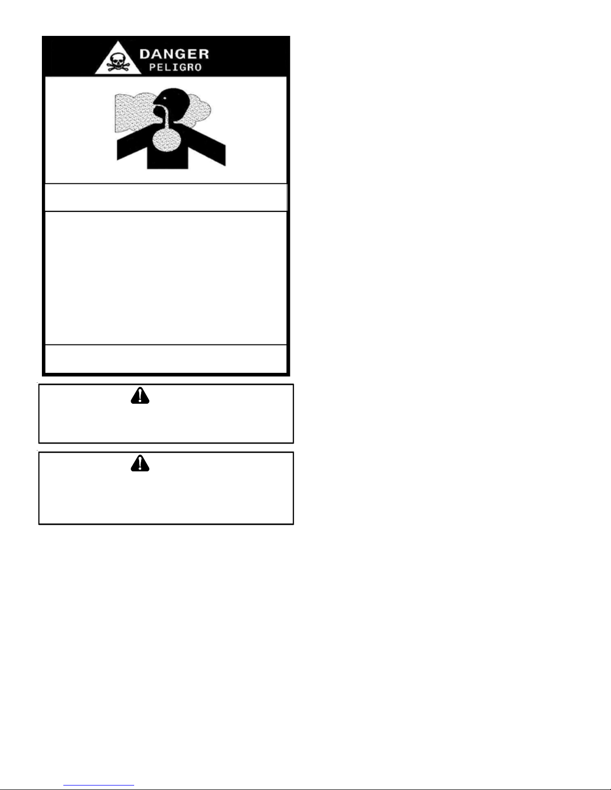
CARBON MONOX IDE POI SONING HAZARD
Spec ial Warnin g f o r In s t a l lat ion of Fur na c e or A ir Ha n dl i n g Un it s in
Enclosed Areas such as Garages, Utility Rooms or Parking Areas
Carbon monoxide prod uc ing devi ces (such as an autom obile, space
heater, g as water heater , etc.) should no t be operated in enclosed areas
such as unventilated garages, utility rooms or parking areas because of
the danger of carbon monoxide (CO) poisoning resulting from the exhaust
emissio ns. If a furnace or air handler is instal led in an enclosed area such
as a garage, utility room or par king area and a carbo n monoxide producing
device is operated there in, there must be adequate, dire ct outside
ventilation.
This ventilation is necessary to avoid the danger of CO poisoning which
can occur if a carbon monoxide producing de vi ce continues to operate in
the enclosed area. Carb on monoxide em issions can be (re)circulated
through out the structure if the furnace or air handler is operating in any
mode.
CO can cause serious illness including permanent brain damage or death.
B10259-216
-
WARNING
S
HOULDOVERHEAT INGOCCURORTHEGASSUPPLYFAILTOSHUTOFF
TURNOFFTHEMANUALGASSHUTOFFVALVEEXTERNALTOTHE
FURNACEBEFORETURNINGOFFTHEELECTRICALSUPPLY
.
,
WARNING
P
OSSIBLEPROPERTYDAMAGE,PERSONALINJURYORDEATHDUETO
FIRE,EXPLOSION,SMOKE,SOOT,COND E NSATION,ELECTRICALSHOCK
ORCARBO NMONOXIDEMAYRESU LTFROMIMPROPERINSTALLATION
REPAIROPERATION,ORMAINTENANCEOFTHISPRODUCT
.
,
SHIPPING INSPECTION
All units are securely packed in shipping containers tested according to International Safe Transit Association specifications.
The carton must be checked upon arrival for external damage. If
damage is found, a request for inspection by carrier’s agent must
be made in writing immediately .
The furnace must be carefully inspected on arrival for damage and
bolts or screws which may have come loose in transit. In the event
of damage the consignee should:
1. Make a notation on delivery receipt of any visible damage
to shipment or container .
2. Notify carrier promptly and request an inspection.
3. With concealed damage, carrier must be notified as soon
as possible - preferably within five days.
4. File the claim with the following support documents within
a nine month statute of limitations.
• Original or certified copy of the Bill of Lading, or indemnity
bond.
• Original paid freight bill or indemnity in lieu thereof.
• Original or certified copy of the invoice, showing trade
and other discounts or reductions.
• Copy of the inspection report issued by carrier’s
representative at the time damage is reported to carrier .
The carrier is responsible for making prompt inspection of damage
and for a thorough investigation of each claim. The distributor or
manufacturer will not accept claims from dealers for transportation
damage.
ELECTROSTATIC DISCHARGE (ESD) PRECAUTIONS
NOTE: Discharge body’s static electricity before touching unit.
An electrostatic discharge can adversely affect electrical components.
Use the following precautions during furnace installation and servicing to protect the integrated control module from damage. By
putting the furnace, the control, and the person at the same electrostatic potential, these steps will help avoid exposing the integrated control module to electrostatic discharge. This procedure
is applicable to both installed and non-installed (ungrounded) furnaces.
1. Disconnect all power to the furnace. Do not touch the
integrated control module or any wire connected to the
control prior to discharging your body’s electrostatic charge
to ground.
2. Firmly touch a clean, unpainted, metal surface of the
furnaces near the control. Any tools held in a person’s
hand during grounding will be discharged.
3. Service integrated control module or connecting wiring
following the discharge process in step 2. Use caution not
to recharge your body with static electricity; (i.e., do not
move or shuffle your feet, do not touch ungrounded objects,
etc.). If you come in contact with an ungrounded object,
repeat step 2 before touching control or wires.
4. Discharge your body to ground before removing a new
control from its container. Follow steps 1 through 3 if
installing the control on a furnace. Return any old or new
controls to their containers before touching any ungrounded
object.
TO THE INSTALLER
Before installing this unit, please read this manual thoroughly to
familiarize yourself with specific items which must be adhered to,
including but not limited to: unit maximum external static pressure, gas pressures, BTU input rating, proper electrical connections, circulating air temperature rise, minimum or maximum CFM,
and motor speed connections.
5
Page 6
IMPORTANT NOTE TO THE OWNER REGARDING PRODUCT WAR-
RANTY
Y our warranty certificate is supplied as a separate document
with the unit installed by your contractor. Read the limited
warranty certificate carefully to determine what is and is not
covered and keep the warranty certificate in a safe place. If
you are unable to locate the warranty certificate please contact your installing contractor or contact customer service (877254-4729) to obtain a copy .
T o receive the Lifetime Heat Exchanger Limited Warranty (good
for as long as you own your home) and the 10-year Parts
Limited Warranty , online registration must be completed within
60 days of installation. Online registration is not required in
California or Quebec. Complete warranty details are available
from your local dealer or, for Goodman
www.goodmanmfg.com, and for Amana® brand products, visit
www.amana-hac.com.
To register your Goodman
www.goodmanmfg.com and click “W arranty Registration”. Complete the registration as prompted.
T o register your Amana® brand unit, go to www .amana-hac.com
and click on “Warranty Registration”. Complete the registration as prompted.
Product limited warranty certificates for models currently in production can be viewed at www.goodmanmfg or www.amanahac.com. If your model is not currently in production or does not
appear on the website, please contact your installing contractor or
contact customer service at (877-254-4729) to obtain a copy of
your warranty certificate.
Each product overview page contains a Product Warranty link; by
clicking on it you will be able to view the limited warranty coverage
for that specific product. T o view warranty registration information,
click on the Product Warranty text on the left navigation panel on
the home page of each website. The Online Product Registration
pages are located in this same section.
WARNING
®
brand products, visit
®
brand unit, go to
However, this reduces the benefit s of the ComfortNet system as
the enhancements will only apply to the furnace.
The modulating furnace operation is based off of negative pressure created by the draft inducer . The furnace control board
receives commands from the room thermostat. The furnace
control board then controls the RPM of the (3 phase) inducer
by varying the frequency and voltage to the inducer . This is
known as variable frequency drive (VFD). The inducer , pressure switches, and gas valve are linked by pneumatic tubing.
The gas valve modulates based on this negative pressure.
*
*
26
9
8
7
10
11
3
12
33
13
15
14
17
16
18
19
20
21
26
27
23
25
10
11
6
5
7
4
3
*
*
2
1
*
*
*
*
*
31
18
19
20
28
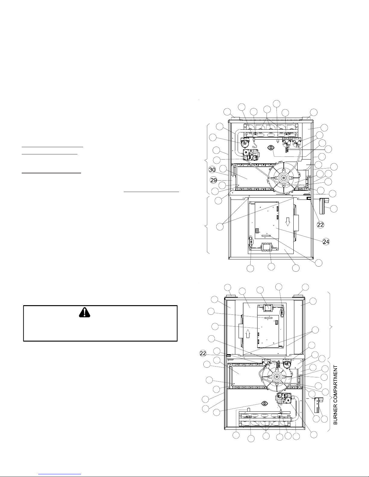
BLOWER COMPARTMENT BURNER COMPARTMENT
23
UPFLOW/HORIZONTAL
5
27
32
25
TO
PREVENTPROPERTYDAMAGE,PERSONALINJURYORDEATHDUETO
FIRE,DONOTINSTALLTHISFURNACEINAMOBILEHOME,TRAILER,OR
RECREATIONALVEHICLE
P
RODUCT DESCRIPTION
.
FEATURES
This furnace is a part of the ComfortNet™ family of products. The
CTK0* thermostat kit allows this furnace to be installed as part of
a digitally communicating system. The ComfortNet system provides automatic airflow configuration, enhanced setup features,
and enhanced diagnostics. It also reduces the number of thermostat wires to a maximum of four. It may be also installed as p art of
a non-communicating system using a standard 24 V AC thermostat.
This product may be installed with the ComfortNet thermostat and
a non-ComfortNet compatible single stage air conditioning unit.
6
20
13
17
18
33
24
3
31
19
12
9
COUNTERFLOW/HORIZONTAL
8
7
28
3
15
29
18
20
2
6
7
1
4
14
BLOWER COMPARTMENT
16
30
19
21
Page 7

1 Gas V alve
2 Gas Line Entrance (Alternate)
3 Pressure Switch(es)
4 Gas Manifold
5 Combustion Air Intake Connection
6 Hot Surface Igniter
7 Rollout Limit
8 Burners
9 Flame Sensor
10 Flue Pipe Connection
11 Flue Pipe
12 Primary Limit
13 Gas Line Entrance
14 Flue Pipe Connection (Alternate)
15 Rubber Elbow
16 Variable-Speed Induced Draft Blower
17 Electrical Connection Inlets (Alternate)
18 Coil Front Cover Pressure Tap
19 Coil Front Cover Drain Port
20 Drain Line Penetrations
21 Drain Trap
22 Blower Door Interlock Switch
23 Inductor (Not All Models)
24 Two-Stage Integrated Control Module
(with fuse and diagnostic LED)
25 24 Volt Thermostat Connections
26 Transformer (40 VA)
27 ECM Variable Speed Circulator Blower
28 Auxiliary Limit
29 Junction Box
30 Electrical Connection Inlets
31 Coil Front Cover
32 Combustion Air Inlet Pipe (*CVM96 only)
33 "H" Fitting
P
RODUCT APPLICA TION
This furnace is primarily designed for residential home-heating applications. It is NOT designed or certified for use in mobile homes,
trailers or recreational vehicles. Neither is it designed or certified
for outdoor applications. The furnace must be installed indoors
(i.e., attic space, crawl space, or garage area provided the garage
area is enclosed with an operating door).
This furnace can be used in the following non-industrial commercial applications:
Schools, Office buildings, Churches, Retail stores,
Nursing homes, Hotels/motels, Common or office areas
In such applications, the furnace must be installed with the following stipulations:
• It must be installed per the installation instructions
provided and per local and national codes.
• It must be installed indoors in a building constructed on
site.
• It must be part of a ducted system and not used in a free
air delivery application.
• It must not be used as a “make-up” air unit.
• It must be installed as a two-pipe system.
• All other warranty exclusions and restrictions apply This
furnace is an ETL dual-certified appliance and is
appropriate for use with natural or propane gas (NOTE: If
using propane, a propane conversion kit is required).
Dual certification means that the combustion air inlet pipe is OPTIONAL and the furnace can be vented as a:
Non-direct vent (single pipe) central forced air furnace in
which combustion air is taken from the installation area
or from air ducted from the outside or ,
Direct vent (dual pipe) central forced air furnace in which
all combustion air supplied directly to the furnace burners
through a special air intake system outlined in these
instructions.
This furnace may be used as a construction site heater ONL Y if
all of the following conditions are met:
• The vent system is permanently installed per these
installation instructions.
• A room thermostat is used to control the furnace. Fixed
jumpers that provide continuous heating CANNOT be
used and can cause long term equipment damage.
• Return air ducts are provided and sealed to the furnace.
• A return air temperature range between 60ºF (16ºC) and
80ºF (27ºC) is maintained.
• Air filters are installed in the system and maintained during
construction replaced as appropriate during construction,
and upon completion of construction.
• The input rate and temperature rise are set per the furnace
rating plate.
• 100% outside air is provided for combustion air
requirements during construction. T emporary ducting can
be used.
NOTE: Do not connect the temporary duct directly to the
furnace. The duct must be sized for adequate combustion
and ventilation in accordance with the latest edition of
the National Fuel Gas Code NFP A 54/ANSI Z223.1 or
CAN/CSA B149.1 Installation Codes.
• The furnace heat exchanger , components, duct system,
air filters and evaporator coils are thoroughly cleaned
following final construction clean up.
• All furnace operating conditions (including ignition, input
rate, temperature rise and venting) are verified according
to these installation instructions.
NOTE: The Commonwealth of Massachusetts requires that the
following additional requirements must also be met:
• Gas furnaces must be installed by a licensed plumber or
gas fitter.
• A T -handle gas cock must be used.
• If the unit is to be installed in an attic, the passageway to
and the service area around the unit must have flooring.
To ensure proper furnace operation, install, operate and
maintain the furnace in accordance with these installation
and operation instructions, all local building codes and ordinances. In their absence, follow the latest edition of the Na-
tional Fuel Gas Code (NFP A 54/ANSI Z223.1), and/or CAN/CSA
7
Page 8
B149.1 Installation Codes, local plumbing or waste water codes,
and other applicable codes.
A copy of the National Fuel Gas Code (NFP A 54/ANSI Z223.1)
can be obtained from any of the following:
American National Standards Institute
1430 Broadway
New Y ork, NY 10018
National Fire Protection Association
1 Batterymarch Park
Quincy , MA 02269
CSA International
8501 East Pleasant V alley
Cleveland, OH 44131
The rated heating capacity of the furnace should be greater than or
equal to the total heat loss of the area to be heated. The total heat
loss should be calculated by an approved method or in accordance with “ASHRAE Guide” or “Manual J-Load Calculations” published by the Air Conditioning Contractors of America.
A copy of the CAN/CSA B149.1 Installation Codes can also be
obtained from:
CSA International
178 Rexdale Boulevard
Etobicoke, Ontario, Canada M9W 1R3
L
OCATION REQUIREMENTS
& C
ONSIDERA TIONS
Follow the instructions listed below and the guidelines provided in
the Combustion and Ventilation Air Requirements section when
selecting a furnace location.
WARNING
TO
PREVENTPOSSIBLEEQUIPM EN TDAMAGE,PROPERTYDAMAGE
PERSONALINJURYORDEATH,THEFOLLOWINGBULLETPOINTSMUSTBE
OBSERVEDWHENINSTALLINGTHISUNIT
.
,
WARNING
P
OSSIBLEPROPERTYDAMAGE,PERSONALINJURYORDEATHDUETO
FIRE,EXPLOSION,SMOKE,SOOT,COND E NSATION,ELECTRICALSHOCK
ORCARBO NMONOXIDEMAYRESU LTFROMIMPROPERINSTALLATION
REPAIROPERATION,ORMAINTENANCEOFTHISPRODUCT
.
,
• Centrally locate the furnace with respect to the proposed
or existing air distribution system.
• Ensure the temperature of the return air entering the
furnace is between 55°F and 100°F when the furnace is
heating.
• Provide provisions for venting combustion products
outdoors through a proper venting system. Special
consideration should be given to vent/flue pipe routing
and combustion air intake pipe when applicable. Refer
to V ent/Flue Pipe and Combustion Air Pipe -T ermination
Locations for appropriate termination locations and to
determine if the piping system from furnace to termination
can be accomplished within the guidelines given. NOTE:
The length of flue and/or combustion air piping can be a
limiting factor in the location of the furnace.
• Locate the furnace so condensate flows downwards to
the drain. Do not locate the furnace or its condensate
drainage system in any area subject to below freezing
temperatures without proper freeze protection. Refer to
Condensate Drain Lines and T rap for further details.
• Ensure adequate combustion air is available for the
furnace. Improper or insufficient combustion air can
expose building occupants to gas combustion products
that could include carbon monoxide. Refer to
Combustion and Ventilation Air Requirements.
• Set the furnace on a level floor to enable proper
condensate drainage. If the floor becomes wet or damp
at times, place the furnace above the floor on a concrete
base sized approximately 1-1/2" larger than the base of
the furnace. Refer to the Horizontal Applications and
Considerations for leveling of horizontal furnaces.
• Ensure upflow or horizontal furnaces are not installed
directly on carpeting, or any other combustible material.
The only combustible material allowed is wood.
• A special accessory subbase must be used for upright
counterflow unit installations over any combustible
material (including wood). Refer to subbase instructions
for installation details. (NOTE: A subbase will not be
required if an air conditioning coil is located beneath the
furnace between the supply air opening and the
combustible floor.
• Exposure to contaminated combustion air will result in
safety and performance-related problems. Do not install
the furnace where the combustion air is exposed to the
following substances:
permanent wave solutions
chlorinated waxes or cleaners
chlorine-based swimming pool chemicals
water softening chemicals
deicing salts or chemicals
carbon tetrachloride
halogen type refrigerants
cleaning solutions (such as perchloroethylene)
printing inks
paint removers
varnishes
hydrochloric acid
cements and glues
antistatic fabric softeners for clothes dryers
and masonry acid washing materials
• Isolate a non-direct furnace from an area contaminated
by any of the above substances. This protects the
non-direct vent furnace from airborne contaminants. T o
ensure that the enclosed non-direct vent furnace has an
adequate supply of combustion air, air must be ducted
in from a nearby uncontaminated room or from outdoors.
Refer to the Combustion and Ventilation Air Requirements
for details.
8
Page 9
• If the furnace is used in connection with a cooling
unit, install the furnace upstream or in parallel with
the cooling coil. Premature heat exchanger failure
will result if the cooling coil is placed upstream of the
furnace.
For vertical (upflow or downflow) applications, the
minimum cooling coil width shall not be less than
furnace width minus 1”. Additionally , a coil inst alled
above an upflow furnace or under a counterflow furnace
may be the same width as the furnace or may be one
size larger than the furnace. Example: a “C” width
coil may be installed with a “B” width furnace.
For upflow applications, the front of the coil and furnace
must face the same direction.
• If the furnace is installed in a residential garage, position
the furnace so that the burners and ignition source are
located not less than 18 inches (457 mm) above the
floor. Protect the furnace from physical damage by
vehicles.
• If the furnace is installed horizontally , ensure the access
doors are not on the “up/top” or “down/bottom” side of the
furnace.
• Do not connect this furnace to a chimney flue that serves
a separate appliance designed to burn solid fuel.
• On Counterflow Installations, the air conditioning coil must
be downstream on the supply (positive) side of the furnace
heat exchanger.
• Counterflow Installation over a noncombustible floor.
Before setting the furnace over the plenum opening, ensure
the surface around the opening is smooth and level. A
tight seal should be made between the furnace base and
floor by using a silicone rubber caulking compound or
cement grout.
• Counterflow Installation over a combustible floor. If
installation over a combustible floor becomes necessary ,
use an accessory subbase (see Specification Sheet
applicable for your model for details.) A special accessory
subbase must be used for upright counterflow unit
installations over any combustible material including wood.
Refer to subbase instructions for installation details. Follow
the instructions with the subbase for proper installation.
Do not install the furnace directly on carpeting, tile, or
other combustible material other than wood flooring.
(NOTE: The subbase will not be required if an air
conditioning coil is installed between the supply air
opening on the furnace and the floor.)
CLEARANCES AND ACCESSIBILITY
• In all cases, accessibility clearance must take precedence over
clearances from the enclosure where accessibility clearances
are greater.
*CVM96* MINIMUM CLEARANCE TO COMBUST IBLE MATERIALS
(INCHES)
POSITION SIDES REAR FRONT BOTTOM FLUE TOP
Downflow 0" 0" 3" NC 0" 1"
Horizontal 6" 0" 3" C 0" 6"
C = If placed on combustible floor, floor MUS T be wood only.
NC = For installation on non-combustible floors only. A combustible subbase
must be used for installations on combustible flooring.
NOTES:
• For servicing or cleaning, a 24” front clearance is required.
• Unit connections (electrical, flue and drain) may necessitate
greater clearances than the minimum clearances listed above.
• In all cases, accessibility clearance must take precedence over
clearances from the enclosure where accessibility clearances
are greater.
Installations must adhere to the clearances to combustible materials to which this furnace has been design certified. The minimum
clearance information for this furnace is provided on the unit’s clearance label. These clearances must be permanently maintained.
Clearances must also accommodate an installation’s gas, electrical, and drain trap and drain line connections. NOTE: In addition
to the required clearances to combustible materials, a minimum of
24 inches service clearance must be available in front of the unit.
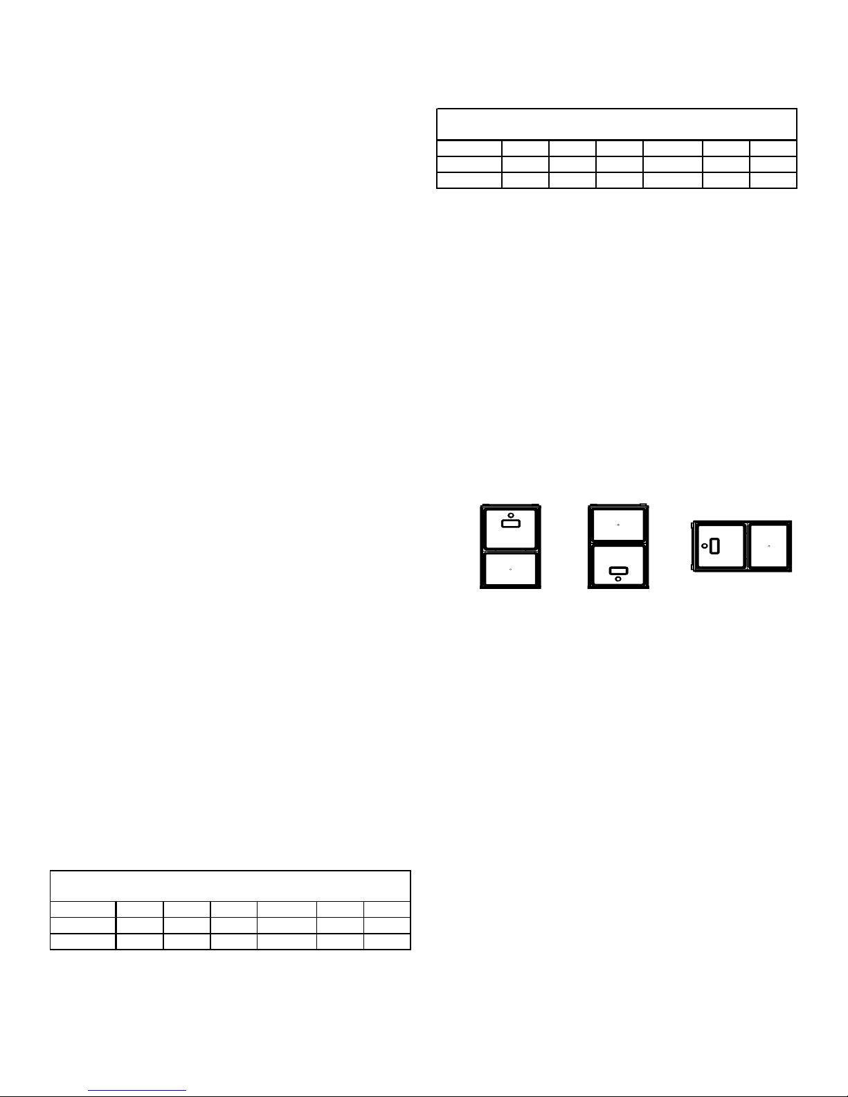
TOP
TOP
SIDE SIDE SIDE
BOTTOM
BOTTOM
Upflow Counterflow Horizontal
EXISTING FURNACE REMOVAL
NOTE: When an existing furnace is removed from a venting sys-
tem serving other appliances, the venting system may be too large
to properly vent the remaining attached appliances.
The following vent testing procedure is reproduced from the Ameri-
can National Standard/National Standard of Canada for GasFired Central Furnaces ANSI Z21.4, CSA-2.3 latest edition
Section 1.23.1.
The following steps shall be followed with each appliance connected to the venting system placed in operation, while any other
appliances connected to the venting system are not in operation:
*MVM96* MI NIMUM CLEARAN CE TO CO MBU STIBLE MATERIALS
(INCHES)
POSITION SIDES REAR FRONT BOTTOM FLUE TOP
Upflow 0" 0" 3" C 0" 1"
Horizontal 6" 0" 3" C 0" 6"
C = If placed on combustible floor, floor M UST be wood only.
NOTES:
• For servicing or cleaning, a 24” front clearance is required.
• Unit connections (electrical, flue and drain) may necessitate
greater clearances than the minimum clearances listed above.
1. Seal any unused openings in the venting system;
2. Inspect the venting system for proper size and horizontal pitch, as required by the National Fuel Gas Code,
ANSI Z223.1 or the Natural Gas and Propane Installation Code, CSA B149.1-05 and these instructions. Determine that there is no blockage or restriction, leakage, corrosion and other deficiencies which could cause
an unsafe condition.
9
Page 10
3. As far as practical, close all building doors and windows and all doors between the space in which the
appliance(s) connected to the venting system are located and other spaces of the building.
4. Close fireplace dampers.
5. Turn on clothes dryers and any appliance not connected
to the venting system. Turn on any exhaust fans, such
as range hoods and bathroom exhausts, so they shall
operate at maximum speed. Do not operate a summer
exhaust fan.
6. Follow the lighting instructions. Place the appliance being
inspected in operation. Adjust thermost at so appliance
shall operate continuously .
7. Test for spillage from draft hood appliances at the draft
hood relief opening after 5 minutes of main burner operation. Use the flame of a match or candle.
8. If improper venting is observed during any of the above
tests, the venting system must be corrected in accordance with the National Fuel Gas Code ANSI Z223.1/
NFP A 54 and/or National Gas and Prop ane Installation
Code CSA B149.1-05.
9. After it has been determined that each appliance connected to the venting system properly vents when tested
as outlined above, return doors, windows, exhaust fans,
fireplace dampers and any other gas burning appliance
to their previous conditions of use.
If resizing is required on any portion of the venting system, use
the appropriate table in Appendix G in the latest edition of the
National Fuel Gas Code ANSI Z223.1 and/or CSA B149.1-05
Installation Codes.
THERMOSTAT LOCATION
The thermostat should be placed approximately five feet from the
floor on a vibration-free, inside wall in an area having good air
circulation. Do not install the thermostat where it may be influenced by any of the following:
• Drafts, or dead spots behind doors, in corners, or under
cabinets.
• Hot or cold air from registers.
• Radiant heat from the sun.
• Light fixtures or other appliances.
• Radiant heat from a fireplace.
• Concealed hot or cold water pipes, or chimneys.
• Unconditioned areas behind the thermostat, such as
an outside wall.
Consult the instructions packaged with the thermostat for
mounting instructions and further precautions.
C
OMBUSTION
& V
ENTILA TION AIR REQUIREMENTS
WARNING
TO
AVOIDPROPERTYDAMAGE,PERSONALINJURYORDEATH
SUFFICIEN TFRESHAIRFORPROPERCOMBUSTIONANDVENTILATIONOF
FLUEGASESMUSTBESUPPLIED
SUPPLIEDINTOTHEFURNACEAREA
.M
OSTHOMESREQUIREOUTSIDEAIRBE
.
,
Improved construction and additional insulation in buildings have
reduced heat loss by reducing air infiltration and escape around
doors and windows. These changes have helped in reducing
heating/cooling costs but have created a problem supplying combustion and ventilation air for gas fired and other fuel burning
appliances. Appliances that pull air out of the house (clothes
dryers, exhaust fans, fireplaces, etc.) increase the problem by
starving appliances of air.
House depressurization can cause back drafting or improper combustion of gas-fired appliances, thereby exposing building occupants to gas combustion products that could include carbon monoxide.
When the furnace is installed as a direct vent (2-pipe system)
furnace, no special provisions for air for combustion are required. However, if this furnace is to be installed in the same
space with other gas appliances, such as a water heater , ensure
there is an adequate supply of combustion and ventilation air for
the other appliances. Refer to the latest edition of the National
Fuel Gas Code NFPA 54/ANSI Z223.1 or CAN/CSA B149 Installation Codes or applicable provisions of the local building codes
for determining the combustion air requirements for the appliances.
Most homes will require outside air be supplied to the furnace
area by means of ventilation grilles or ducts connecting directly
to the outdoors or spaces open to the outdoors such as attics or
crawl spaces.
The following information on air for combustion and ventilation is
reproduced from the National Fuel Gas Code NFPA 54/ANSI
Z223.1 Section 9.3.
9.3* Air for Combustion and Ventilation.
9.3.1 General.
9.3.1.1 Air for combustion, ventilation, and dilution of flue gases for
appliances installed in buildings shall be obtained by application of one of
the methods covered in 9.3.2 through 9.3.6. Where the requirements of
9.3.2 are not met, outdoor air shall be introduced in accordance with methods covered in 9.3.3 through 9.3.6.
Exception No. 1: This provision shall not apply to direct vent appliances.
9.3.1.2 Appliances of other than natural draft design and other than Category 1 vented appliances shall be provided with combustion, ventilation,
and dilution air in accordance with the appliance manufacturer’s instructions.
9.3.1.3 Appliances shall be located so as not to interfere with proper
circulation of combustion, ventilation, and dilution air.
10
Page 11
9.3.1.4 Where used, a draft hood or a barometric draft regulator shall be
installed in the same room or enclosure as the appliance served so as to
prevent any difference in pressure between the hood or regulator and the
combustion air supply.
9.3.1.5 Makeup air requirements for the operation of exhaust fans, kitchen
ventilation systems, clothes dryers, and fireplaces shall be considered in
determining the adequacy of a space to provide combustion air requirements.
9.3.2 Indoor Combustion Air. The required volume of indoor air shall be
determined in accordance with the method in 9.3.2.1 or 9.3.2.2 except that
where the air infiltration rate is known to be less than 0.40 ACH, the
method in 9.3.2.2 shall be used. The total required volume shall be the sum
of the required volume calculated for all appliances located within the
space. Rooms communicating directly with the space in which the appliances are installed through openings not furnished with doors, and through
combustion air openings sized and located in accordance with 9.3.2.3, are
considered a part of the required volume.
9.3.2.1* Standard Method. The minimum required volume shall be 50 ft
3
per 1,000/Btu/hour (4.8m3/kW).
9.3.2.2* Known Air Infiltration Rate Method. Where the air infiltration
rate of a structure is known, the minimum required volume shall be determined as follows:
(1) For appliances other than fan-assisted, calculate using the following
equation:
Required Volume
> ________ _________
other
(2) For fan-assisted appliances, calculate using the following equation:
Required Volume
> ________ _________
fan
3
21 ft
I
other
ACH 1000 Btu/hr
3
15 ft
I
fan
ACH 1000 Btu/hr
where:
I
I
= all appliances other than fan-assisted input in Btu per hour
other
= fan-assisted appliances input in Btu per hour
fan
ACH = air change per hour (percent of volume of space exchanged
per hour, expressed as a decimal)
Figure A.9.2.3.3.(1) All Combustion Air from Adjacent
Indoor Spaces through Indoor Combustion Air Openings.
(2) Combining spaces in different stories. The volumes of spaces in dif-
ferent stories shall be considered as communicating spaces where such
spaces are connected by one or more openings in doors or floors
having a total minimum free area of 2 in.2/1000 Btu/hr (4400 mm2/kW)
of total input rating of all appliances.
9.3.3 Outdoor Combustion Air. Outdoor combustion air shall be provided through opening(s) to the outdoors in accordance with the methods
in 9.3.3.1 or 9.3.3.2. The minimum dimension of air openings shall not be
less than 3 in. (80 mm).
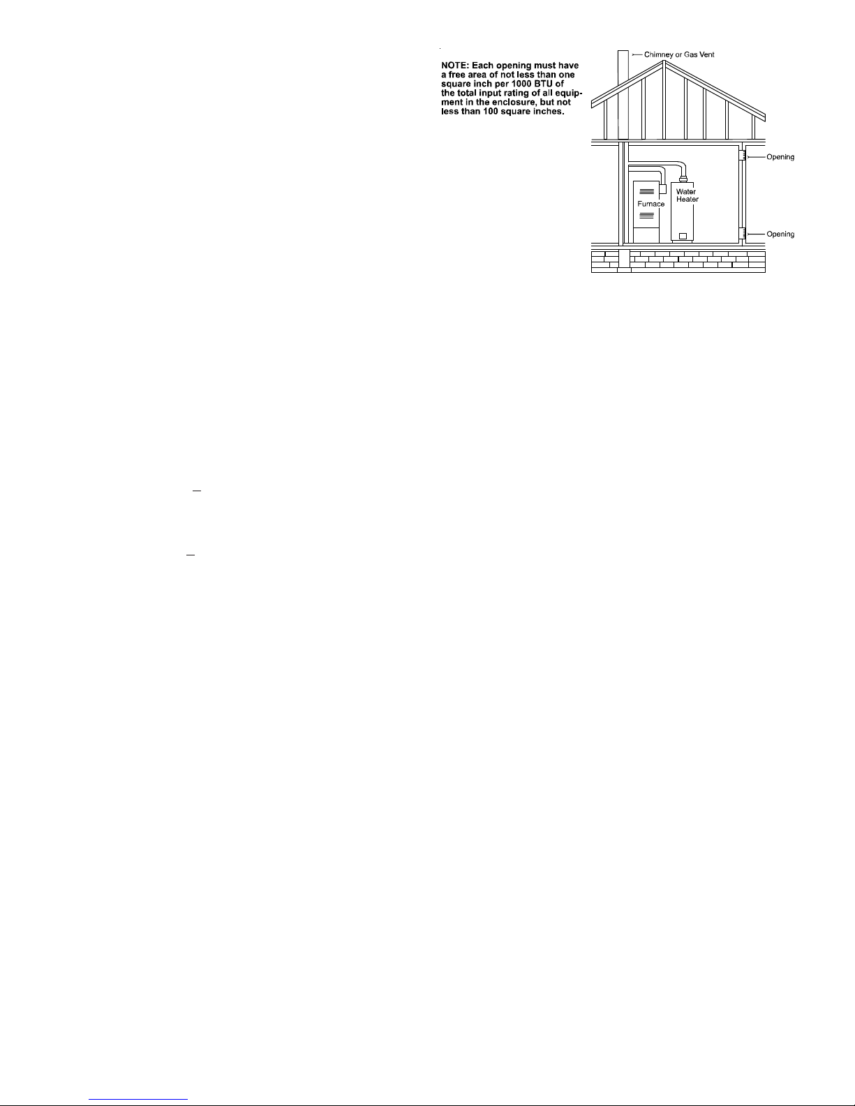
9.3.3.1 Two Permanent Openings Method. Two permanent openings,
one commencing within 12 in. (300 mm) of the top and one commencing
within 12 in. (300 mm) of the bottom, of the enclosure shall be provided.
The openings shall communicate directly, or by ducts, with the outdoors
or spaces that freely communicate with the outdoors, as follows:
(1)*Where directly communicating with the outdoors or where communi-
cating to the outdoors through vertical ducts, each opening shall have
a minimum free area of 1 in.2/4000 Btu/hr (550 min2/kW) of total input
rating of all appliances in the enclosure. [See Figure A.9.3.3.1(1)(a)
and Figure A.9.3.3.1(1)(b).]
(3) For purposes of this calculation, an infiltration rate greater than 0.60
ACH shall not be used in the equations in 9.3.2.2(1) and 9.3.2.2(2).
9.3.2.3 Indoor Opening Size and Location. Openings used to connect
indoor spaces shall be sized and located in accordance with the following:
(1)*Combining spaces on the same story . Each opening shall have a mini-
mum free area of 1 in.2/1000Btu/hr (2200 mm2/kW) of the total input
rating of all appliances in the space but not less than 100 in.2 (0.60m2).
One opening shall commence within 12 in. (300 mm) of the top, and
one opening shall commence within 12 in. (300 mm) of the bottom, of
the enclosure [see Figure A.9.3.2.3(1)]. The minimum dimension of
air openings shall be not less than 3 in. (80 mm).
11
Page 12
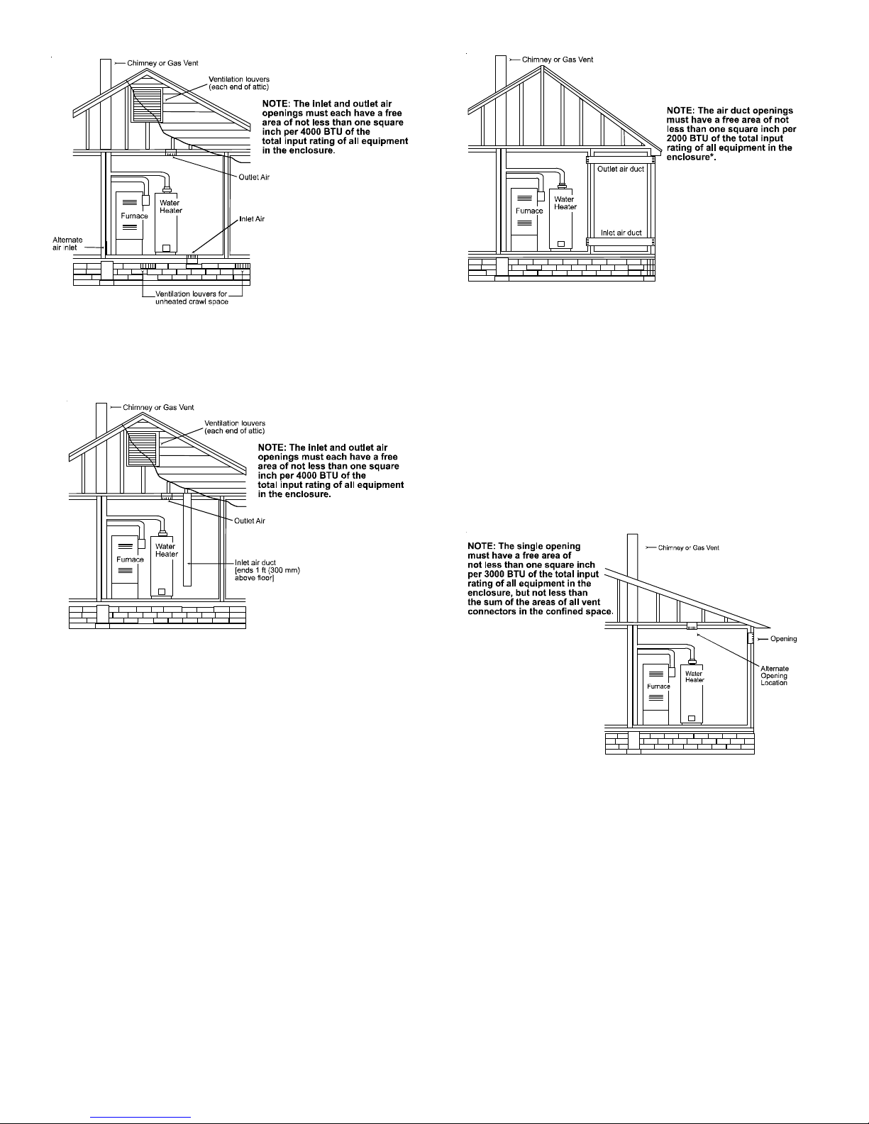
Figure A.9.3.3.1(1)(a) All Combustion Air From Outdoors -
Inlet Air from Ventilated Crawl Space and Outlet Air
to Ventilated Attic.
Figure A.9.3.3.1(1)(b) All Combustion Air
From Outdoors through Ventilated Attic.
(2)* Where communicating with the outdoors through horizontal ducts,
each opening shall have a minimum free area of 1 in.2/2000 Btu/hr
(1100 min2/kW) of total input rating of all appliances in the enclosure.
[See Figure A.9.3.3.1(2).]
Figure A.9.3.3.1(2) All Combustion Air From Outdoors
through Horizontal Ducts.
9.3.3.2* One Permanent Opening Method. One permanent openings,
commencing within 12 in. (300 mm) of the top of the enclosure, shall be
provided. The appliance shall have clearances of at least 1 in. (25 mm)
from the sides and back and 6 in. (150 mm) from the front of the appliance.
The opening shall directly communicate with the outdoors or shall communicate through a vertical or horizontal duct to the outdoors or spaces
that freely communicate with the outdoors (see Figure A.9.3.3.2) and shall
have a minimum free area of the following:
(1) 1 in.
2
/3000 Btu/hr (700 mm2 per kW) of the total input rating of all
appliances located in the enclosure, and
(2) Not less than the sum of the areas of all vent connectors in the space.
Figure A.9.3.3.2 All Combustion Air
From Outdoors through Single Combustion Air Opening.
9.3.4 Combination Indoor and Outdoor Combustion Air. The use of a
combination of indoor and outdoor combustion air shall be in accordance
with (1) through (3) (see example calculation in Annex J]:
(1) Indoor Openings: Where used, openings connecting the interior spaces
shall comply with 9.3.2.3.
(2) Outdoor Opening(s) Location. Outdoor opening(s) shall be located in
accordance with 9.3.3.
(3) Outdoor Opening(s) Size. The outdoor opening(s) size shall be calcu-
lated in accordance with the following:
(a) The ratio of the interior spaces shall be the available volume of
all communicating spaces divided by the required volume.
(b) The outdoor size reduction factor shall be 1 minus the ratio of
interior spaces.
12
Page 13
(c) The minimum size of outdoor opening(s) shall be the full size of
outdoor opening(s) calculated in accordance with 9.3.3, multiplied by the reduction factor. The minimum dimension of air
openings shall not be less than 3 in. (80 mm).
9.3.8.5 Ducts shall not be screened where terminating in an attic space.
9.3.8.6 Horizontal upper combustion air ducts shall not slope downward
toward the source of combustion air.
9.3.5 Engineered Installations. Engineered combustion air installations
shall provide an adequate supply of combustion, ventilation, and dilution
air and shall be approved by the authority having jurisdiction.
9.3.6 Mechanical Combustion Air Supply. Where all combustion air is
provided by a mechanical air supply system, the combustion air shall be
supplied form outdoors at the minimum rate of 0.35 ft
hr (0.034 m
9.3.6.1 Where exhaust fans are installed, additional air shall be provided to
replace the exhausted air.
9.3.6.2 Each of the appliances served shall be interlocked to the mechanical
air supply system to prevent main burner operation where the mechanical
air supply system is not in operation.
9.3.6.3 Where combustion air is provided by the building’s mechanical
ventilation system, the system shall provide the specified combustion air
rate in addition to the required ventilation air.
9.3.7 Louvers, Grilles, and Screens.
9.3.7.1 Louvers and Grilles. The required size of openings for combus-
tion, ventilation, and dilution air shall be based on the net free area of each
opening. Where the free area through a design of louver or grille or screen is
known, it shall be used in calculating the size opening required to provide
the free area specified. Where the louver and grille design and free area are
not known, it shall be assumed that wood louvers will have 25 percent free
area, and metal louvers and grilles will have 75 percent free area.
Nonmotorized louvers and grilles shall be fixed in the open position.
3
/min per kW) for all appliances located within the space.
3
/min per 1000 Btu/
9.3.8.7 The remaining space surrounding a chimney liner, gas vent, special
gas vent, or plastic piping installed within a masonry, metal, or factory
built chimney shall not be used to supply combustion air.
Exception: Direct vent appliances designed for installation in a solid fuelburning fireplace where installed in accordance with the manufacture’s
installation instructions.
9.3.8.8 Combustion air intake openings located on the exterior of the
building shall have the lowest side of the combustion air intake openings
located at least 12 in. (300 mm) vertically from the adjoining grade level.
I
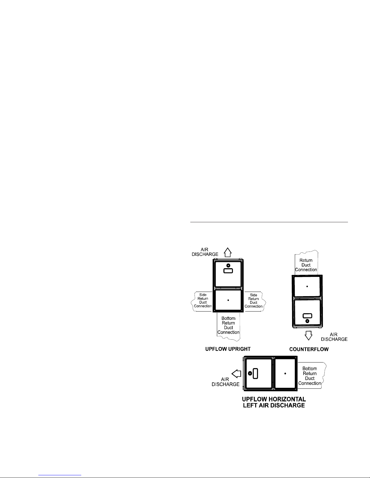
NST ALLA TION POSITIONS
A/GMVM96 models may be installed upflow or horizontally
with left or right side down. A/GCVM96 models may be installed downflow or horizontally with left or right side down.
Do not install this furnace on its back. For upright upflow fur-
naces, return air ductwork may be attached to the side panel(s)
and/or basepan. For horizontal upflow furnaces, return air ductwork must be attached to the basepan. For both upright or
horizontal counterflow furnaces, return ductwork must be attached
to the basepan (top end of the blower compartment). NOTE:
Ductwork must never be attached to the back of the furnace.
Refer to “Recommended Installation Positions” figure for appropriate installation positions, ductwork connections, and resulting
airflow arrangements.
9.3.7.2 Minimum Scree Mesh Size. Screens shall not be smaller than 1/
4 in. mesh.
9.3.7.3 Motorized Louvers. Motorized louvers shall be interlocked with
the appliance so they are proven in the full open position prior to main
burner ignition and during main burner operation. Means shall be provided
to prevent the main burner form igniting should the louver fail to open
during burner startup and to shut down the main burner if the louvers close
during burner operation.
9.3.8 Combustion Air Ducts. Combustion air ducts shall comply with
9.3.8.1 through 9.3.8.8.
9.3.8.1 Ducts shall be constructed of galvanized steel or a material having
equivalent corrosion resistance, strength, and rigidity.
Exception: Within dwellings units, unobstructed stud and joist spaces shall
not be prohibited from conveying combustion air, provided that not more
than one fireblock is removed.
9.3.8.2 Ducts shall terminate in an unobstructed space, allowing free movement of combustion air to the appliances.
9.3.8.3 Ducts shall serve a single space.
9.3.8.4 Ducts shall not serve both upper and lower combustion air open-
ings where both such openings are used. The separation between ducts
servicing upper and lower combustion air openings shall be maintained to
the source of combustion air.
13
Page 14

Recommended Installation Positions
H
ORIZONT AL APPLICA TIONS
& C
ONSIDERA TIONS
When installing a furnace horizontally , additional consideration must
be given to the following:
FURNACE SUSPENSION
If suspending the furnace from rafters or joists, use 3/8" threaded
rod and 2”x2”x1/8” angle iron as shown in the following diagram.
The length of rod will depend on the application and the clearances
necessary .
If the furnace is installed in a crawl space it must be suspended
from the floor joist or supported by a concrete pad. Never install
the furnace on the ground or allow it to be exposed to water.
LEVELING
Leveling ensures proper condensate drainage from the heat exchanger and induced draft blower . For proper flue pipe drainage,
the furnace must be level lengthwise from end to end. The furnace
should also be level from back to front or have a slight tilt with the
access doors downhill (approximately 3/4 inches) from the back
panel. The slight tilt allows the heat exchanger condensate, generated in the recuperator coil, to flow forward to the recuperator coil
front cover.
ALTERNATE ELECTRICAL AND GAS LINE CONNECTIONS
This furnace has provisions allowing for electrical and gas line connections through either side panel. In horizontal applications the
connections can be made either through the “top” or “bottom” of
the furnace.
DRAIN PAN
A drain pan must be provided if the furnace is installed above a
conditioned area. The drain pan must cover the entire area under
the furnace (and air conditioning coil if applicable).
FREEZE PROTECTION
Refer to Horizontal Applications and Conditions - Drain T rap and
Lines.
2" 2" 3/8"
ANGLE IRON
XX
(3
PLACES
)
DRAIN TRAP AND LINES
In horizontal applications the condensate drain trap is secured to
the furnace side panel, suspending it below the furnace. A minimum clearance of 4 3/4 inches below the furnace must be provided for the drain trap. Additionally, the appropriate downward
piping slope must be maintained from the drain trap to the drain
location. Refer to Condensate Drain T rap and Lines for further details. If the drain trap and drain line will be exposed to temperatures
near or below freezing, adequate measures must be taken to prevent condensate from freezing.
P
ROP ANE GAS/HIGH AL TITUDE INST ALLA TIONS
WARNING
P
OSSIBLEPROPERTYDAMAGE,PERSONALINJURYORDEATHMAY
OCCURIFTHECORRECTCONVERSIONKITSARENOTINSTALLED
APPROPRIATEKITSMUSTBEAPPLIEDTOENSURESAFEANDPROPER
FURNACEOPERATION
QUALIFIEDINSTALLERORSERVICEAGENCY
.ALL
CONVERSIONSMUSTBEPERFORMEDBYA
.
.THE
This furnace is shipped from the factory configured for natural gas
up to 10,000 ft. altitude. Propane conversions require the proper
LP kit to compensate for the energy content difference between natural and propane gas.
LP kits include a manifold assembly, including an LP gas
valve, orifices and LP burners.
Altitude Kit
Gas
Natural None
Propane LPKMOD*****
0-10,000
Orifice
#45
1.25MM
Manifold Pressure
Low Stage
High
(50% firing
Stage
1
3.5" w.c. 1" w.c. Non e
2
10.0" w.c. 2.6" w.c. None
rate)
Pressure
Switch
Change
NOTE:
In Canada, gas furnaces are only certified to 4500 feet .
1
Except 115,000 B TU: #43
2
Except 115,000 B TU: #55
For furnaces being converted to LP gas, it is strongly recommended that a LPLP03 kit also be installed. The use of this kit
will prevent the furnace from firing when the LP gas supply
pressure is too low to support proper combustion.
14
Page 15
Furnace Model LP K it
A/GMVM960603BX
A/GMVM960805CX
A/GMVM961005DX
A/GMVM961155DX
A/GCVM960604CX LPKMOD060CF
A/GCVM960805DX LPKMOD080CF
A/GCVM961005DX LPKMOD100CF
LPKMOD060UF
LPKMOD080UF
LPKMOD100UF
LPKMOD115UF
The indicated kits must be used to insure safe and proper furnace
operation. All conversions must be performed by a qualified installer, or service agency .
V
ENT/FLUE PIPE
& C
OMBUSTION AIR PIPE
It is the responsibility of the installer to follow the manufacturers’
recommendations and to verify that all vent/flue piping and connectors are compatible with furnace flue products. Additionally, it is
the responsibility of the installer to ensure that all piping and connections possess adequate structural integrity and support to prevent flue pipe separation, shifting, or sagging during furnace operation.
DUAL CERTIFICATION: NON-DIRECT/DIRECT VENT
This furnace is dual certified and may be installed as a non-direct
vent (single pipe) or direct vent (dual pipe) appliance. A non-direct
vent installation requires only a vent/flue pipe, while a direct vent
installation requires both a vent/flue pipe and a combustion air
intake pipe. Refer to the appropriate section for details concerning
piping size, length, number of elbows, furnace connections, and
terminations.
WARNING
F
AILURETOFOLLOWTHESEINSTRUCTIO N SCANRESU LTINBODILY
INJURYORDEATH
GIVENINTHISSECTION
.C
AREFULLYREADANDFOLLOWALLINSTRUCTIONS
.
WARNING
U
PONCOMPLETIONOFTHEFURNACEINSTALLATION,CAREFULLY
INSPECTTHEENTIREFLUESYSTEMBOTHINSIDEANDOUTSID EOFTHE
FURNACETOASSUREITISPROPERLYSEALED
SYSTEMCANRESU LTINSERIOUSPERSONALINJURYORDEATHDUETO
EXPOSURETOFLUEPRODUCTS,INCLUDINGCARBO NMONOXIDE
.L
EAKSINTHEFLUE
.
A condensing gas furnace achieves its high level of efficiency by
extracting almost all of the heat from the products of combustion
and cooling them to the point where condensation takes place.
Because of the relatively low flue gas temperature and water condensation requirements, PVC or ABS pipe is used as venting
material.
In addition to PVC and ABS pipe and fittings, Innoflue® by
Centrotherm Eco Systems and PolyPro® by M&G Duravent
are also approved vent and combustion air materials for installations in the U.S.A. and Canada. Manufacturers Installation
instructions for these products must be followed. These products have specific instructions for installing, joining and terminating. Do not mix materials or components of one manufacturer with materials or components of another manufacturer .
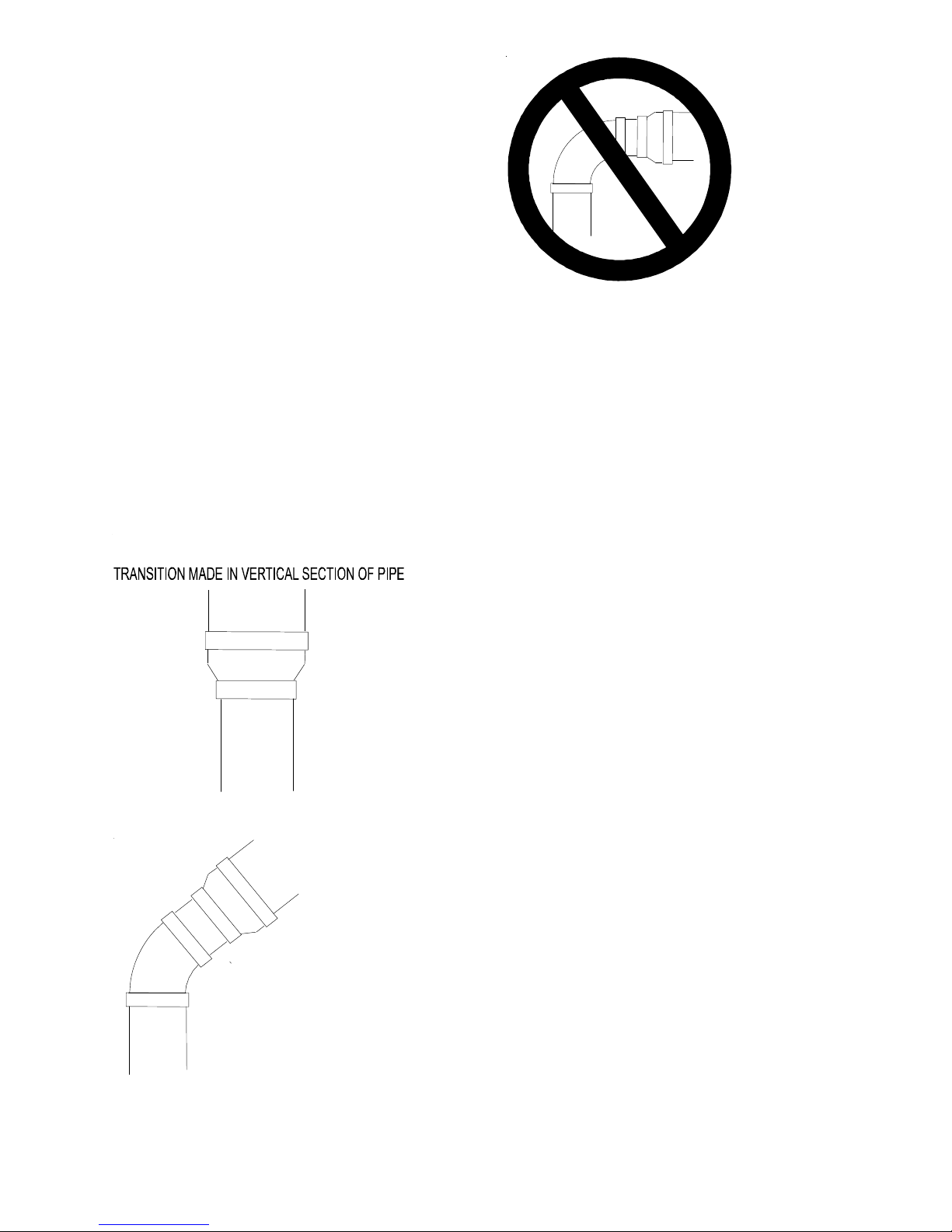
All furnaces are built with 2" vent / intake pipe and connectors. For furnaces requiring installation of 3" pipe, the transition from 2" to 3" should be done as close to the furnace as
practically possible.
This furnace must not be connected to T ype B, BW , or L vent or
vent connector, and must not be vented into any portion of a factory built or masonry chimney except when used as a pathway for
PVC as described later in this section. Never common vent this
appliance with another appliance or use a vent which is used by a
solid fuel appliance.
WARNING
TO
AVOIDBODILYINJURY,FIREOREXPLOSION,SOLVENTCEMENTS
MUSTBEKEPTAWAYFROMALLIGNITIONSOURCES(I.E
FLAMES,ANDEXCESSIVEHEAT)ASTHEYARECOMBUSTIBLELIQUIDS
VOIDBREATHINGCEMENTVAPO RSORCONTA C TWITHSKINAND/OR
A
EYES
.
.,
SPARKS,OPEN
.
MATERIALS AND JOINING METHODS
Two- or three-inch nominal diameter PVC Schedule 40 pipe meeting ASTM D1785, PVC primer meeting ASTM F656, and PVC
solvent cement meeting ASTM D2564 specifications must be used.
Fittings must be DWV type fittings meeting ASTM D2665 and
ASTM D331 1. Carefully follow the pipe manufacturer’s instructions for cutting, cleaning, and solvent cementing of PVC.
The use of Schedule 40 PVC or ABS cellular core (Foam Core)
plastic pipe is also acceptable as a flue/vent and intake pipe material. PVC primer meeting ASTM F656 and PVC solvent cement
meeting ASTM D2564 specifications must be used. Fittings must
be DWV type fittings meeting ASTM D2665 and ASTM D3311.
Carefully follow the manufactures instructions for cutting, cleaning
and solvent cementing of PVC.
For Canadian installations; all PVC pipe, fittings and joining
materials must be UL S636 listed.
As an alternative to PVC pipe, primer, solvent cement, and
fittings, ABS materials which are in compliance with the following specifications may be used: Two-or-three-inch solid
wall ABS Schedule 40 pipe must meet ASTM D1527 and, if
used in Canada, must be CSA listed or, two-or-three-inch
cellular core ABS Schedule 40 pipe must meet ASTM F628
and, if used in Canada, must be CSA listed. Solvent cement
for ABS to ABS joints must meet ASTM D2235 and, if used in
Canada, must be CSA listed. The solvent cement for the PVC
to ABS transition joint must meet ASTM D3138. Fittings must
be DWV type fittings meeting ASTM D2661 and ASTM D331 1
and, if used in Canada, must be CSA listed. Carefully follow
the manufacturers’ instructions for cutting, cleaning, and solvent cementing PVC and/or ABS.
15
Page 16
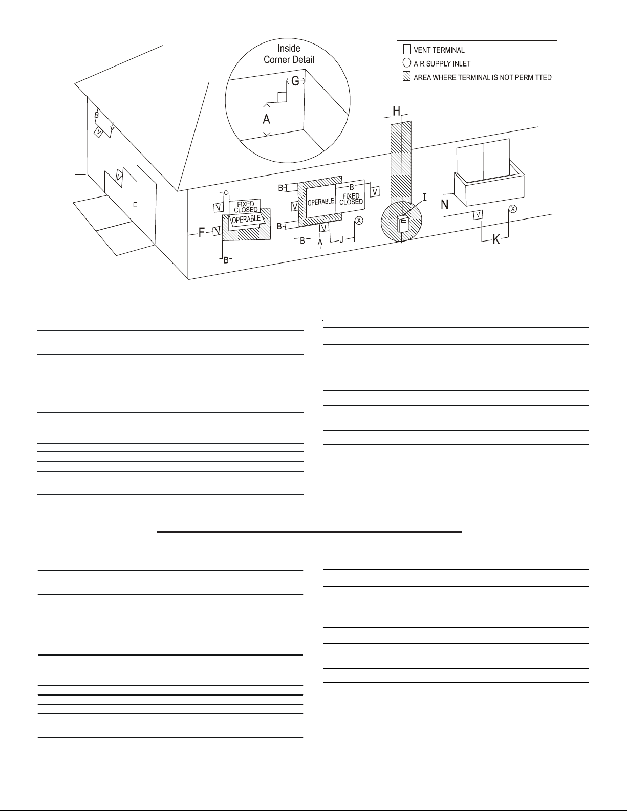
DIRECT VENT TERMINAL CLEARANCES
A= Clearance above grade,
veranda, porch, deck or
balcony. (See 1.24.6-i(9)b.)
B= Clearance to window or
door that may b e opened.
C= Clearance to permanently
closed window.
D= Vertical clearance to ventilated soffit
located above the terminal within a
horizontal distance of 2 feet (61 cm)
from the center line of the terminal.
E= Clearance to unventilated soffit. * *
F= Clearance to outside corner. * *
G= Clearance to inside corner. * *
H= Clearance to each side of center
line exten ded ab o ve meter / regulator
assembly.
Canadian Installations
12 in. (30 cm) 12 in. (30 cm)
6 in. (15 cm) for appliances
10,000 Btuh (3 kW), 12 in. (30 cm) for
appliances > 10,000 Btuh (3 kW) and
100,000 Btuh (30 kW), 36 in. (91 cm)
for appliances > 100,000 Btuh (30
kW).
**
**
3 ft. (91 cm) within a height 15 ft.
(4.5 m) above the meter/regulator
assembly.
1
v
U.S. Installations
6 in. (15 cm) for appliances
10,000 Btuh (3 kW), 9 in. (23 cm) for
appliances > 10,000 Btuh (3 kW) and
50,000 Btuh (15 kW), 12 in. (30 cm) for
appliances > 500,000 Btuh (15 kW).
*
2
V
X
I= Clearance to service
regulator vent outlet.
J= Clearance to nonmechanical air
supply inlet to building or the
combustion air inlet to any other
appliance.
K= Clearan ce to a mechanical
air supply inlet.
L= Clearance above paved sidewalk or
paved driveway located on public
property.
M= Clearance under veranda, porch,
deck or balcony.
1 In accordance with the current CSA B149.1, Natural Gas and Propane Installation Code.
2 In accordance with the current ANSI Z223.1/NFPA 54, National Fuel Gas Code.
† A vent shall not terminate directly above a sidewalk or paved driveway that is located between two single family dwellings and serves
both dwellings.
‡ Permitted only if veranda, porch, deck or balcony is fully open on a minimum of two sides beneath the floor.
* For clearances not specified in ANSI Z223.1/NFPA 54 or CSA B149.1, the following statement shall be included:
“Clearance in accordance with local installation codes and the requirements of the gas supplier and the manufacturer’s installation instruction.”
Canadian Installations
3 ft. (91 cm). *
6 in. (15 cm) for appliances 10,000
Btuh (3 kW), 12 in. (30 cm) for
appliances > 10,000 Btuh (3kW) and
100,000 Btuh (30 kW), 36 in. (91 cm)
for appliances > 100,000 Btuh (30 kW).
6 ft. (1.83 m) 3 ft. (91 cm) above if within
7 ft. (2.13m) † *
12 in. (30 cm) ‡ *
1
U.S. Installations
6 in. (15 cm) for appliances 10,000
Btuh (3 kW), 9 in. (23 cm) for
appliances > 10,000 Btuh (3kW) and
50,000 Btuh (15 kW), 12 in. (30 cm) for
appliances > 50,000 Btuh (15 kW).
10 ft. (3 m) horiz ontally.
2
OTHER THAN DIRECT VENT TERMINAL CLEARANCES
A= C learance above grade,
veranda, porch, deck or
balcony. (See 1.24.6-i(9)b.)
B= C learance to window or
door that may be opened.
C= Clearance to permanently
closed window.
D= Vertical clearance to ventilated soffit
located above the terminal within a
horizontal distance of 2 feet (61 cm)
from the center line of the terminal.
E= C learance to unventilated soffit. * *
F= Clearance to outside corner. * *
G= Clearance to inside corner. * *
H= Clearance to each side of center
line extended above meter/regulator
assembly.
Canadian Installations
12 in. (30 cm) 12 in. ( 30 cm )
6 in. (15 cm) for appliances
10,000 Btuh (3 kW), 12 in. (30 cm) for
appliances > 10,000 Btuh (3 kW) and
100,000 Btuh (30 kW), 36 in. (91 cm)
for appliances > 100,000 Btuh (30
kW).
**
**
3 ft. (91 cm) within a height 15 ft.
(4.5 m) above the meter/regulator
assembly.
1
U.S. Installations
4 ft. (1.2 m) below or to side of
opening; 1 ft. (300 m) above opening.
*
2
I= Clearance to sevice
regulator vent outlet.
J= Clearance to nonmechanical air
supply inlet to building or the
combustion air inlet to any other
appliance.
K= Clearance to a mechanical
air supply inlet.
L= Clearance above paved sidewalk or
paved driveway located on public
property.
M= Clearance under veranda, porch,
deck or balcony.
1 In accordance with the current CSA B149.1, Natural Gas and Propane Installation Code.
2 In accordance with the current ANSI Z223.1/NFPA 54, National Fuel Gas Code.
† A vent shall not terminate directly above a sidewalk or paveable driveway that is located between two single family dwellings and serves
both dwelling.
‡ Permitted only if veranda, porch, deck or balcony is fully open on a minimum of two sides beneath the floor.
* For clearances not specified in ANSI Z223.1/NFPA 54 or CSA B149.1, the following statement shall be included:
“Clearance in accordance with local installation codes and the requirements of the gas supplier and the manufacturer’s installation instruction.”
Canadian Installations
3 ft. (91 cm). *
6 in. (15 cm) for appliances 10,000
Btuh (3 kW), 12 in. (30 cm) for
appliances > 10,000 Btuh (3kW) and
100,000 Btuh (30 kW), 36 in. (91 cm)
for appliances > 100,000 Btuh (30 kW).
6 ft. (1.83 m) 3 ft. (91 cm) above if within
7 ft. (2.13m) † 7 ft. (2.13m)
12 in. (30 cm) ‡ *
1
U.S. Installations
4 ft. (1.2 m) below or to side of
opening; 1 ft. (300 m) above opening.
10 ft. (3 m) horizontally.
16
2
Page 17
All 90° elbows must be medium radius (1/4 bend DWV) or long
radius (Long sweep 1/4 bend DWV) types conforming to ASTM
D331 1. A medium radius (1/4 bend DWV) elbow measures 3 1/
16” minimum from the plane of one opening to the centerline of the
other opening for 2” diameter pipe, and 4 9/16” minimum for 3”
pipe.
The use of two short radius 45 degree elbows is permitted to
provide clearance to refrigerant piping above the furnace.
PROPER VENT/FLUE AND COMBUSTION AIR PIPING PRACTICES
Adhere to these instructions to ensure safe and proper furnace
performance. The length, diameter , and number of elbows of the
vent/flue pipe and combustion air pipe (when applicable) affects
the performance of the furnace and must be carefully sized. All
piping must be installed in accordance with local codes and these
instructions.
Piping must be adequately secured and supported to prohibit sagging, joint separation, and/or detachment from the furnace. Horizontal runs of vent/flue and combustion air piping must be properly supported. PVC pipe supports must be no more than 5'
apart. For ABS pipe, supports must be no more than 3' apart.
Horizontal pipe runs must maintain a 1/4 inch per foot downward
slope, back towards the furnace, to properly return condensate to
the furnace’s drain system.
PREFERRED
ACCEPTABLE
TRANSITION NO LESS
THAN 45 DEGREES TO
HORIZONTAL PLANE TO
AVOID CREATING A W ATER
TRAP IN VENT PIPING.
NO TRANSI TION ON
HORIZONTAL PL ANE,
THIS CREATES A
WATER TRAP AND
RESTRICTS FLUE
GASES
Precautions should be taken to prevent condensate from freezing
inside the vent/flue pipe and/or at the vent/flue pipe termination. All
vent/flue piping exposed to temperatures below 35°F for extended
periods of time must be insulated with 1/2” thick closed cell foam.
Also, all vent/flue piping exposed outdoors in excess of the terminations shown in this manual (or in unheated areas) must be insulated with 1/2” thick closed cell foam. Inspect piping for leaks
prior to installing insulation.
TERMINATION LOCATIONS
NOTE: Refer to Location Requirements and Considerations for
combustion air contaminant restrictions.
The following bullets and diagram describe the restrictions con-
cerning the appropriate location of vent/flue pipe and combustion
air intake pipe (when applicable) terminations. Refer to Non-Direct
Vent (Single Pipe) Piping and Direct Vent (Dual Pipe) Piping located in this section for specific details on termination construction.
• All terminations (flue and/or intake) must be located at
least 12 inches above ground level or the anticipated
snow level.
• Vent terminations (non-direct and direct vent) must
terminate at least 3 feet above any forced air inlet located
within 10 feet.
NOTE: This provision does not apply to the combustion
air intake termination of a direct vent application.
• The vent termination of a direct vent application must
terminate at least 12 inches from any opening through
which flue gases may enter a building (door, window , or
gravity air inlet).
• The vent termination running vertically through a roof
must terminate at least 12 inches above the roof line (or
the anticipated snow level) and be at least 12 inches
from any vertical wall (including any anticipated snow
build up).
• A vent termination shall not terminate over public walkways
or over an area where condensate or vapor could create
a nuisance or hazard or could be detrimental to the
operation of regulators, relief valves, or other equipment.
• The combustion air intake termination of a direct vent
application should not terminate in an area which is
frequently dusty or dirty .
NOTE: In Canada, the current edition of CAN/CSA B149.1
takes precedence over the preceding termination restriction.
17
Page 18
3
REMOVE
PIPE
4
REMOVE
AND RELOCATE
CABINET GROMMET
2
DETACH RUBBER
ELBOW FROM
ID BLOWER AND
VENT/FLUE
PIPE
5
5
EXTERNALLY
EXTERNALLY
MOUNT
MOUNT
RUBBER ELBOW
RUBBER ELBOW
AND SECURE FLANGE
AND SECURE FLANGE
WITH 4 SCREWS
WITH 4 SCREWS
REMOVED IN STEP 1
REMOVED IN STEP 1
3
REMOVE
PIPE
INSTALL CABINET GROMMET
IN 2 LOCATIONS
2
REMOVE
3 SCREWS
RUBBER ELBOW
AND SECURE FLANGE
WITH 4 SCREWS
4
REMOVED IN STEP 1
DETATCH RUBBER
ELBOW FROM
ID BLOWER AND
VENT/FLUE
PIPE
ID BLOWER WITH
RUBBER COUPLING
COUNTERFLOW-HORIZONTAL MODEL ALTERNATE VENT
TO USE ALTERNATE
COMBUSTION
AIR LOCATION, REMOVE
INTERNAL PIPE AS PER
ABOVE. CAP UNUSED
CABINET OPENINGS
CABINET WITH
5
7
EXTERNALLY
MOUNT
6
SECURE TO
AND HOSE
CLAMPS
SECURE TO
SCREWS
ALTERNATE
COMBUSTION
AIR LO CATION
ON C’FLOW -HOR
MODELS
COUNTERFLOW- HOR IZONTAL MODEL
AL TER NATE CO MBUST ION AI R LOCATION
18
Page 19

SPECIAL VENTING REQUIREMENTS FOR INSTALLATIONS IN
CANADA
All installations in Canada must conform to the requirements
of CAN/CSA B149.1 code. All vent system components, including primer and cement, must be listed to ULC S636. The
certified pipe and fittings should be clearly marked with the
ULC standard “S636”. The primer and cement used must be
of the same manufacturer as the vent system. For Royal Pipe
System 636; use GVS-65 Primer (Purple) and GVS-65 PVC
Solvent Cement. For IPEX System 636, use PVC/CPVC
Primer, Purple or clear . Use PVC Solvent Cement (Gray).
For Canadian installations, ABS may be used as a combustion air pipe only. ABS is not an approved vent material in
Canada. If ABS is used as a combustion air pipe, it must be
CSA certified. Always follow the manufacturer’s instructions
in the use of primer and cement. Do not use primer and cement around potential sources of ignition. Do not use primer
or cement beyond its expiration date.
The safe operation, as defined by ULC S636, of the vent system is based on following these installation instructions, the
vent system manufacturer’s installation instructions, and proper
use of primer and cement. It is recommended under this standard, that the vent system be checked once a year by qualified service personnel. All fire stop s and roof flashings used
with this system must be UL listed. Acceptability under CAN/
CSA B149.1 is dependent upon full compliance with all installation instructions. Consult the authority having jurisdiction
(gas inspection authority , municipal building department, fire
department, etc.) before installation to determine the need to
obtain a permit. *IPEX System 636™ is a trademark of IPEX
Inc.
Carefully follow the pipe manufacturers’ instructions for cutting,
cleaning, and solvent cementing PVC and/or ABS.
The vent can be run through an existing unused chimney provided
the space between the vent pipe and the chimney is insulated and
closed with a weather-tight, corrosion-resistant flashing.
STANDARD FURNACE CONNECTIONS
It is the responsibility of the installer to ensure that the piping
connections to the furnace are secure, airtight, and adequately
supported.
Upflow/horizontal models are shipped with one 2" rubber coupling to attach the vent pipe to the furnace. Counterflow/horizontal models are shipped with two 2" rubber couplings for
attaching the vent pipe and combustion air pipe/fitting to the
furnace. Rubber couplings are typically shipped in the furnace
drain trap.
densate drain lines, etc. If necessary, clearances may be
increased by creating an offset using two 45 degree elbows.
This joint can be rotated on the fitting to establish maximum clearance between refrigerant lines, metering devices, and condensate drain lines, etc. This joint is the equivalent of one 90 deg.
elbow when considering elbow count.
45 DEGREE
ELBOWS
Increased Clearance Configuration
The vent/flue pipe can also be secured using a PVC or ABS elbow
or coupling using the appropriate glue (see Materials and Joining
Methods).
NOTE: For non-direct vent installations, a minimum of one 90°
elbow should be installed on the combustion air intake coupling to
guard against inadvertent blockage.
COMBUSTION AIR PIPE
DIRECT VENT INSTALLATIONS
On upflow units secure the combustion air intake pipe directly to
the air intake coupling. On counterflow units secure the combustion air intake pipe to the air intake coupling using the rubber coupling and worm gear hose clamps provided with the unit. The counterflow rubber coupling allows service removal of air intake piping
internal to the furnace blower compartment. The combustion air
intake pipe can also be secured directly to the counterflow unit air
intake pipe coupling.
NON-DIRECT VENT INSTALLATIONS
A minimum of one 90° elbow should be installed on the combustion air intake “coupling” to guard against inadvertent blockage.
(DIRECT VENT ONLY)
90 PVC
ELBOW
(NON-DIRECT VENT)
COMBUSTION
AIR PIPE
OR
RUBBER
COUPLING
WITH WORM
GEAR CLAMPS
VENT/FLUE
PIPE
90 PVC
ELBOW
(NON-DIRECT VENT)
COMBUSTION
AIR PIPE
(DIRECT VENT ONLY)
GEAR CLAMPS
OR
RUBBER
COUPLINGS
WITH WORM
VENT/FLUE
PIPE
VENT/FLUE PIPE
Vent/flue pipe can be secured to the vent/flue coupling using the
rubber coupling and worm gear hose clamps provided with this
furnace (see “St andard Connections” figure). The rubber coupling
allows separation of the vent/flue pipe from the furnace during servicing. Combustion Air and V ent piping should be routed in a manner to avoid contact with refrigerant lines, metering devices, con-
UPFLOW COUNTERFLOW
Standard Connections
19
Page 20

ALTERNATE FURNACE CONNECTIONS
FLANGE
If the standard locations are undesirable for a specific installation,
alternate side panel locations are available for both combustion air
inlet and vent/flue pipe connections on counterflow-horizontal
models. On upflow-horizontal models, only an alternate vent
location is provided.
NOTE: St andard and alternate locations can be combined (i.e.,
an installation may use the standard combustion air intake location but use the alternate vent/flue location or vice versa), if needed.
WARNING
E
DGESOFSHEETMETALHOLESMAYBESHARP
PRECAUTIONWHENREMOVINGHOLEPLUGS
.
.USE
GLOVESASA
ALTERNATE VENT/FLUE LOCATION
The alternate vent/flue location is the large hole directly in line with
the induced draft blower outlet. T o use the alternate vent/flue location refer to the following steps and the “Alternate Vent/Flue Location” figure.
NOTE: In the horizontal left installation position, a means of
condensate collection must be provided to keep vent pipe
condensate from entering the draft inducer housing. If the ventdrain elbow is eliminated from the installation; an RF000142
kit must be used.
1. Remove and save the four screws securing the vent/flue
coupling to the furnace top panel.
Counterflow units.
Remove and save the four screws securing the vent/flue
coupling to the furnace. Also remove the three screws
securing the furnace’s internal vent/flue piping to the blower
deck.
2. Upflow and Counterflow units.
Loosen the worm gear hose clamps on the rubber elbow
and detach it from both the induced draft blower and the
vent/flue pipe.
3. Upflow and Counterflow units.
Remove the vent/flue pipe from the furnace.
4. Cut the vent/flue pipe 3.75 inches from the flanged end of
the pipe (see “Vent/Flue Pipe Cuts” figure). The section of
pipe attached to the coupling will reach through the side
panel to the induced draft blower . Discard remaining pipe
and elbows.
Counterflow units.
Cut the vent/flue pipe 3.75 inches from the blower deck
coupling (see “Vent/Flue Pipe Cuts” figure). Save vent/flue
pipe attached to blower deck coupling for use in the alternate
location. Discard remaining pipe and elbows.
3.75"
CUT HERE
Vent/Flue Pipe Cuts
5. Remove plastic plug from alternate vent/flue location.
Relocate and install plug in standard vent/flue location (top
cover).
Counterflow units.
Remove plastic plug from alternate vent/flue location.
Relocate and install grommet in standard vent/flue location
(basepan). Grommet remaining hole in blower deck with
plastic plug included in the drain kit bag.
6. Upflow and Counterflow units.
Insert cut section of vent/flue pipe and coupling into alternate
vent/flue location. Using a rubber coupling and worm gear
hose clamps from the drain kit bag, attach the vent/flue
pipe and coupling to the induced draft blower . Secure the
coupling to the cabinet using the screws removed in step 1
or with field-supplied 3/8” #8 self tapping screws.
WARNING
THE
RUBBERELBOWISNOTDESIGNEDTOSUPPORTALOAD
RUBBERELBOWISMOUNTEDEXTERNALLYTOTHEFURNACECABIN E T
EXTREMECAREMUSTBETAKENTOADEQUATELYSUPPORTFIELD
SUPPLIEDVENT/FLUEPIPING,ASDAMAGECANRESU LTINLEAKS
CAUSINGBODILYINJURYORDEATHDUETOEXPOSURETOFLUEGASES
INCLUDINGCARBONMONOXIDE
.W
HENTHE
,
‐
,
7. Upflow and Counterflow units.
For upright installations, externally mount the rubber
elbow to the vent/flue coupling using a worm gear hose
clamp. Secure field supplied vent/flue piping to the rubber
elbow using a worm gear hose clamp. NOTE: Use of the
alternate vent/flue location for upright installations, requires
the drain trap be installed on the same side of the unit as
the flue pipe.
ALTERNATE COMBUSTION AIR INTAKE LOCATION - COUNTERFLOW/
HORIZONTAL MODELS ONLY
The alternate combustion air intake location consists of a large,
unobstructed hole (alternate vent connection is aligned with the
Induced Draft Blower). T o use the alternate combustion air intake
location, refer to the following steps, and the “Alternate Combustion Air Intake Location” figure.
1. Remove and save the four screws securing the combustion
air intake coupling. Remove an additional three screws
securing the furnace’s internal combustion air intake pipe
to the blower deck.
20
Page 21

2. Remove the combustion air intake pipe from the furnace
and cut the pipe at the basepan coupling. Save the basepan
coupling and gasket from the blower deck coupling for use
in the alternate location. Discard the remaining pipe.
3. Remove plastic plug from alternate combustion air intake
location. Relocate and install plug in standard air intake
location (basepan). Grommet the remaining hole in the
blower deck with the plastic plug included in the drain kit
bag.
4. With the gasket facing the cabinet side panel, and the
flange’s flat spot facing forward, secure the combustion air
intake coupling to the cabinet using the screws removed in
step 1 or with field-supplied 3/8” #8 self -tapping screws.
CAUTION
BE
SURENOTTODAMAGEINTERNALWIRINGOROTHERCOMPONENTS
WHENREIN STALLINGCOUPLINGANDSCREWS
.
5. For non-direct vent installations installed horizontally, a
minimum of one 90° elbow should be installed on the
combustion air intake coupling to guard against inadvertent
blockage. No elbow is required on the alternate combustion
air intake of upright installations, however, a minimum
clearance of 2 inches is required to assure proper air supply .
6. For direct vent installations, secure field-supplied
combustion air intake pipe directly to the air intake coupling.
NOTE: A PVC coupling or elbow is required on counterflow
units.
NON-DIRECT VENT (SINGLE PIPE) PIPING
must be counted as an elbow when determining the number of
elbows in the piping system.
*MVM9/*CVM9 Direct Vent (2 - Pipe) and Non-Direct Vent (1- Pipe)
Maxim um Allow able Le ngth of Vent/Flue Pipe & Com bustion A ir P ip e (ft)
Uni t I nput
100,000
100,000 3 250 243 236 229 222 215 208 201 194
115,000
115,000 3 220 213 206 199 192 185 178 171 164
1) Maximum allowable limits listed on individual lengths for inlet and flue
2) Minimum requirement for each vent pipe is five (5) feet in length and
3) Tee used in the vent/flue termination must be included when determin-
4) 2 1/2” or 3” diameter pipe can be used in place of 2” diameter pipe.
5) Increased Clearance Configurations using (2) 45 deg. elbows should
6) One 90° elbow should be secured to the combustion air intake con-
Pipe Size
(Btu)
60,000
80,000
80,000 3 250 243 236 229 222 215 208 201 194
(4)
(in.)
or 2 1/ 2
or 2 1/ 2
or 2 1/ 2
or 2 1/ 2
and NOT a combination.
one elbow/tee.
ing the number of elbows in the piping system.
be considered equivalent to one 90 deg. elbow.
nection.
012345678
2
250 245 240 235 230 225 220 215 210
2
250 245 240 235 230 225 220 215 210
2
90 85 80 75 70 65 60 55 50
2
75 70 65 60 55 50 45 40 35
Num be r of Elbows
(3) (5 )
(6)
(1) (2 )
VENT/FLUE PIPE TERMINATIONS
Non-direct vent installations require only a vent/flue pipe. The vent
pipe can be run horizontally with an exit through the side of the
building or run vertically with an exit through the roof of the building.
The vent can also be run through an existing unused chimney;
however, it must extend a minimum of 12 inches above the top of
the chimney . The space between the vent pipe and the chimney
must be closed with a weather-tight, corrosion-resistant flashing.
For details concerning connection of the vent/flue pipe to the furnace, refer to Vent/Flue Pipe and Combustion Air - Standard Fur-
nace Connections or Alternate Furnace Connections for specific
details. Refer to the following Non-Direct Vent (Single Pipe) Piping
- Vent/Flue Pipe Terminations for specific details on termination
construction.
Although non-direct vent installations do not require a combustion
air intake pipe, a minimum of one 90° elbow should be attached to
the furnace’s combustion air intake. This elbow will guard against
inadvertent blockage of the air intake.
VENT/FLUE PIPE LENGTHS AND DIAMETERS
Refer to the following table for applicable length, elbows, and pipe
diameter for construction of the vent/flue pipe system of a nondirect vent installation. In addition to the vent/flue pipe, a single 90°
elbow should be secured to the combustion air intake to prevent
inadvertent blockage. The tee used in the vent/flue termination
NOTE: If either a 90 degree or 45 degree elbow is used for
termination, it must be pointed downward.
The vent/flue pipe may terminate vertically , as through a roof, or
horizontally , as through an outside wall.
Vertical vent/flue pipe terminations should be as shown in the following figure. Refer to Vent/Flue Pipe and Combustion Air Pipe -
T ermination Locations for details concerning location restrictions.
The penetration of the vent through the roof must be sealed tight
with proper flashing such as is used with a plastic plumbing vent.
Horizontal vent/flue pipe terminations should be as shown in the
following figure. Refer to Vent/Flue Pipe and Combustion Air Pipe
- T ermination Locations for details concerning location restrictions.
A 2 3/8” diameter wall penetration is required for 2” diameter pipe.
A 3” diameter hole is required for a 2 1/2” pipe and a 3 1/2” diameter hole is required for 3” diameter pipe. The wall penetration
should be sealed with silicone caulking material.
In a basement installation, the vent/flue pipe can be run between
joist spaces. If the vent pipe must go below a joist and then up into
21
Page 22

the last joist space to penetrate the header , two 45° elbows should
be used to reach the header rather than two 90° elbows.
NOTE: Terminate both pipes in the same pressure zone
(same side of roof, no major obstacles between pipes,
etc.).
TEE (OPTIONAL)
COMBUSTION AIR INT AKE
(OPTIONAL)
*Not required for
single pipe installation
E
N
I
L
F
O
O
R
INTAKE
SCREEN
OPTIONAL
6
9
12” MIN TO ROOF OR HIGHEST
ANTICIPATED SNOW LEVEL
ELBOWS
STRAIGHT
_____________________________________
12" MIN.
VENT/FLUE TEE (
12" MIN. ABOVE
HIGHEST ANTI CIPATED
SNOW LE VEL
or
45° ELBO W
TURNED DOWN or
90° ELBOW TURNED
DOWN
12” MIN
HEIGHT DIFFERENCE
BETWEEN
INT A KE AN D VENT
”
3
-
.
X
A
M
”
OPTIONAL)
.
N
I
M
terminations must be in the same atmospheric pressure zone.
Example: Same side of structure, no major obstacles between pipes, etc.
VENT/FLUE & COMBUSTION AIR PIPE LENGTHS &DIAMETERS
Refer to the following table for applicable length, elbows, and pipe
diameter for construction of the vent/flue and combustion air intake
pipe systems of a direct vent (dual pipe) installation. The number
of elbows tabulated represents the number of elbows and/or tees
in each (Vent/Flue & Combustion Air Intake) pipe. If there is a
difference between the two pipes, count the pipe with the most
fittings. Elbows and/or tees used in the terminations must be
included when determining the number of elbows in the piping
systems.
If the combustion air intake pipe is to be installed above a finished
ceiling or other area where dripping of condensate will be objectionable, insulation of the combustion air pipe may be required.
Use 1/2” thick closed cell foam insulation such as Armaflex™ or
Insultube™ where required.
VENT/FLUE AND COMBUSTION AIR PIPE TERMINATIONS
The vent/flue and combustion air pipes may terminate vertically , as
through a roof, or horizontally , as through an outside wall.
Refer to Vent/Flue Pipe and Combustion Pipe - T ermination Locations for details concerning location restrictions. The penetrations
through the roof must be sealed tight with proper flashing such as
is used with a plastic plumbing vent.
Horizontal terminations should be as shown in the following figure.
Refer to Vent/Flue Pipe and Combustion Pipe - Termination Lo-
cation for location restrictions. A 2 3/8” diameter wall penetration
is required for 2” diameter pipe. A 3” diameter hole is required for
a 2 1/2” pipe and a 3 1/2” diameter hole is required for 3”
diameter pipe. The wall penetration should be sealed with silicone caulking material.
Horizontal Termination (Single Pipe)
Above Highest Anticipated Snow Level
DIRECT VENT (DUAL PIPE) PIPING
The inlet air screens provided in the installation instruction packet
are available for the installer to use in the inlet of the combustion air
pipe to prevent animals from building nests in the combustion air
pipe. Installation of screens, while strongly recommended, is not
required and will not affect performance of the unit.
Direct vent installations require both a combustion air intake and a
vent/flue pipe. The pipes may be run horizontally and exit through
the side of the building or run vertically and exit through the roof of
the building. The pipes may be run through an existing unused
chimney; however, they must extend a minimum of 12 inches
above the top of the chimney. The space between the pipes and
the chimney must be closed with a weather tight, corrosion resistant flashing. Both the combustion air intake and a vent/flue pipe
22
Page 23

10”- 24”
6” MAX
4” MIN
90º OR 45°
ELBOW
SCREEN
(OPTIONAL)
12" MIN. TO GRADE OR
HIGHEST ANTICIPATED
SNOW LEVEL
Standard Horizontal Terminations (Dual Pipe)
Vent & Combustion Air Intake Measurements for Standard Horizontal T erminations (Dual Pipe)
Center to center = 10” min / 24” max.
Vertical separation: 0” - 24”
Vent termination from wall = 8” min / 12” max.
Combustion air intake from wall = 6” max.
Vent and intake clearance to ground
or anticipated snow level = 12” min.
_____________________________________
90°
ELBOWS
90°
ELBOWS
3”-24” BETWEEN PIPES
AIR
INTAKE
SCREEN
(OPTIONAL)
12" MIN. ABOVE
HIGHEST ANTICIPATED
SNOW LEVEL
Combustion Air Intake may also be snorkeled to obtain 12” min ground
clearance.
Alternate Vent Termination Above Anticipated Snow Level
(Dual Pipe)
VENT/I NTAKE TERMINATIONS FOR INSTALLATION OF MULTIPLE
DIRECT VENT FURNACES
If more than one direct vent furnace is to be installed vertically
through a common roof top, maintain the same minimum clearances between the exhaust vent and air intake terminations of
adjacent units as with the exhaust vent and air intake terminations
of a single unit.
If more than one direct vent furnace is to be installed horizontally
through a common side wall, maintain the clearances as in the
following figure. Always terminate all exhaust vent outlet s at the
same elevation and always terminate all air intakes at the same
elevation.
3” - 24”
AIR
INTAKE
SCREEN
(OPTIONAL)
12" MIN. ABOVE
HIGHEST ANTICIPATED
SNOW LEVEL
Alternate Horizontal Vent Termination (Dual Pipe)
3” - 24”
12” MIN SEPARATION
3” MIN
OPTIONAL
INTAKE
SCREENS
12” MIN TO GRADE OR HIGHEST
ANTICIPATED SNOW LEVEL
Termination of Multiple Direct Vent Furnaces
CONCENTRIC VENT TERMINATION
Refer to the directions provided with the Concentric Vent Kit (DCVK)
for installation specifications.
23
Page 24

SIDE WALL VENT KIT
Horizontal Installation
This is necessary to prohibit any interference with the
function of the furnace’s drain trap.
NOTE: In vertical installations, air conditioning coil
condensate may drain into the furnace trap as long as there
is a trap between the coil and the furnace trap and the drain
pipe is not terminating below the water level of the furnace
trap.
Vertical Installation
Side Wall Vent Kit
This kit is to be used with 2” or 3” direct vent systems. The vent kit
must terminate outside the structure and may be installed with the
intake and exhaust pipes located side-by-side or with one pipe
above the other. This kit is NOT intended for use with single pipe
(indirect vent) installations.
Refer to the directions furnished with the Side Wall Vent Kit
(p/n 0170K00000S) for installation specifications.
C
ONDENSA TE DRAIN LINES
& D
RAIN TRAP
A condensing gas furnace achieves its high level of efficiency by
extracting heat from the products of combustion to the point where
condensation takes place. The condensate must be collected in
the furnace drain trap and routed to an appropriate drain
location in compliance with local and national codes.
In upright installations, the furnace’s drain hoses may exit either
the right or left side of the furnace. NOTE: If the alternate vent/
flue outlet is utilized in an upright installation, the drain trap and
drain connections must be located on the same side as the alternate vent/flue outlet.
In horizontal installations, the drain hoses will exit through the bot-
tom (down side) of the unit with the drain trap suspended beneath
the furnace. The field-supplied drain system must be in accordance with all local codes and the instructions in the following
sections.
Follow the bullets listed below when installing the drain system.
Refer to the following sections for specific details concerning furnace drain trap installation and drain hose hook ups.
• The drain trap supplied with the furnace must be used.
• The drain line between furnace and drain location must
meet local and nation codes.
• The drain line between furnace and drain location must
maintain a 1/4 inch per foot downward slope toward the
drain.
• Do not trap the drain line in any other location than at
the drain trap supplied with the furnace.
• If the drain line is routed through an area which may
see temperatures near or below freezing, precautions
must be taken to prevent condensate from freezing
within the drain line.
• If an air conditioning coil is installed with the furnace, a
common drain may be used. An open tee must be
installed in the drain line, near the cooling coil, to
relieve positive air pressure from the coil’s plenum.
STANDARD RIGHT OR LEFT SIDE DRAIN HOSE CONNECTIONS
All installation positions require the use of the drain trap, hoses,
tubes, and clamps. The following quantity of hoses, tubes, and
hose clamps are provided with the unit.
HOSE A
QTY : 1
HOSE B
QTY: 1
DRAIN TRAP
QTY: 1
GREEN
HOSE CLAMPS
QTY: 3
RED
HOSE CLAMP
QTY: 1
Hose and Tube Identification
TUBE 1
QTY: 1
SILVER
HOSE CLAMP
QTY: 1
TUBE 2
QTY : 2
UPRIGHT INSTALLATIONS-TRAP ON RIGHT SIDE
In a upright installation drain hoses are connected to bottom drain
port on the rubber elbow and the recuperator coil front cover. The
drain lines are then routed through the right side panel and into the
drain trap secured to the outside of the cabinet.
NOTE: Refer to Alternate Vent/Flue Hose Connections for up-
right installations using an alternate vent/flue outlet.
1. Remove the rubber plug from the right side of the front cover
drain port.
2. Secure Hose A to front cover drain port with a red hose
clamp. Route hose to rear side panel grommet hole.
3. Cut and remove 1/4 inch from the end of the drain port on
the rubber elbow.
4. Insert Tube 1 into rubber elbow drain port and secure with
silver hose clamp. Angle tube outward toward front of furnace.
5. Cut 17 3/4 inches from the long end of Hose B and discard.
Secure the remaining hose to Tube 1 with a green hose
clamp. Route the other end of Hose B to front right side
panel grommet hole.
6. Insert short end of each of tube 2 through side panel
grommet holes. Secure tubes to hoses A and B with green
hose clamps. Ensure hoses and tubes maintain a downward
slope for proper drainage and that they are not kinked or
binding.
24
Page 25

FRONT
COVER
DRAIN
PORT
RUBBER ELBOW
(EXTERNALLY
MOUNTED)
HOSE B
RUBBER
ELBOW
DRAIN PORT
SILVER HOSE CLAMP
TUBE 1
GREEN HOSE
CLAMPS
(3 PLACES)
RIGHT SIDE
PANEL
RUBBER
ELBOW
RUBBER ELBOW
DRAIN PORT
SIL VE R HO SE CLAMP
TUBE 1
HOSE
SIDE PANEL
B
GROMMET
HOLES
TUBE(S) 2
RED HOSE
CLAMP
HOSE A
TUBE(S) 2
DRAIN TRAP
Upright “Alternate” Connections - Right Side
(Upflow Shown, Counterflow Similar)
ALTERNATE VENT/FLUE DRAIN HOSE CONNECTIONS
Upright installations using the alternate vent/flue outlet will require
“right-side only” drain hoses to be connected as follows.
Vent/Flue Pipe and Combustion Air Pipe for details on alternate
vent/flue pipe connection.
1. Remove the rubber plug/cap from the right-side drain port
on the front cover . Save for use in step 3.
2. Secure Hose A to front cover drain port with a red hose
clamp. Route hose to rear right side panel grommet hole.
3. Remove grommet from front right-side panel drain hole.
Seal hole in grommet with large end of plug. Reinstall
grommet and plug into side panel drain hole.
4. Cut 1/4 inch from the end of the drain port on the externally
mounted rubber elbow. Discard cut portion.
5. Insert Tube 1 into rubber elbow drain port and secure with
a silver hose clamp. Angle tube toward trap.
6. Cut 17 3/4 inches from the long end of Hose B and discard.
7. Secure straight end of Hose B to exposed end of Tube 1
with a green hose clamp. Route hose toward right side
panel grommet holes.
8. Insert short end of one Tube 2 through rear right side panel
grommet drain hole. Secure tube to Hose A with a green
hose clamp.
9. Insert short end of remaining Tube 2 into Hose B from rubber
elbow and secure with green hose clamp. Ensure hoses
and tubes maintain a downward slope for proper drainage
and are not kinked or binding.
Refer to
FRONT
COVER
DRAIN PORT
RED HOSE
CLAMP
HOSE
A
GREEN
HOSE
CLAMPS
(3 PLACES)
DRAIN
TRAP
Upright “Standard” Connections - Right Side Only
(Upflow Shown, Counterflow Similar)
UPRIGHT INSTALLATIONS-TRAP ON LEFT SIDE
NOTE: For left side trap installation, grommets must be moved
to the left side of the furnace and the plugs installed on the right
side of the furnace.
1. Remove the rubber plug/cap from the left side drain port
on the front cover.
2. Secure Hose A to front cover drain port with a red hose
clamp. Route hose to rear side panel grommet hole.
3. Cut and remove 1/4 inch from the end of the drain port
on the rubber elbow.
4. Insert Tube 1 into rubber elbow drain port and secure
with silver hose clamp. Angle tube outward toward front
of furnace.
5. Refer to following Drain Hose B T able for hose “B” and
trim to appropriate length (determined by furnace
cabinet width). Secure remaining hose to Tube 1 with a
green hose clamp. Route other end of Hose B to front
left side panel grommet hole.
NOTE: Long hose “B” must always be connected to Tube 1
and the elbow and not on the front cover.
6. Insert short end of each Tube 2 through side panel
grommet holes. Secure tubes to Hose A and Hose B with
green hose clamps. Ensure hoses and tubes maintain a
downward slope for proper drainage and that they are not
kinked or binding.
25
Page 26

LEFT
80 5
SIDE PA NEL
FRONT COVER
DRAIN PORT
RED HOSE
CLAMP
HOSE A
SIDE PA NE L
DRAIN
HOLES
TUBE(S) 2
DRAIN
TRAP
GREEN
HOSE CLAMP
HOSE B
RUBBER
ELBOW
RUBBER
ELBOW
DRAIN PORT
SIL VER HOSE
CLAMP
TUBE 1
GREEN HOSE
CLAMP
Upright “Standard” Connections - Left Side
(Upflow Shown, Counterflow Similar)
Cabinet Width
(inches)
17 1/2 60_3 7
21
Models
(kBTU_Tons)
60_4
80_5
100_5
115_5
"X" Lengt h to Cut From Lo ng
End of Ho se B
(inches)
3 1/2
None24 1/2
Drain Hose “B” Table
UPRIGHT DRAIN TRAP MOUNTING (LEFT OR RIGHT SIDE PANEL)
1. Insert drain tubes into drain trap and position the drain
trap against the side panel. NOTE: Drain tubes must
reach the bottom of the drain trap.
2. Secure drain trap to side panel at the mounting holes
(dimples or crosshairs on counterflow models) located
below the grommet drain holes.
3. Attach PVC drain line to drain trap outlet with either a 90°
elbow or coupling.
HORIZONTAL INSTALLATIONS
RIGHT SIDE DOWN
Horizontal installations with the right side down require that the
drain hoses be connected to the right side front cover drain port
and the rubber elbow drain port.
GREEN HOSE
CLAMP
HOSE B
LEFT SIDE
PANEL
FRONT
COVER
PRESSURE
TAP
FRONT CO VER
DRAIN PORT
RED HOSE CLAMP
SIDE PANEL
GROMMET
HOLES
HOSE A
GREEN HOSE
CLAMP
TUBE(S) 2
DRAIN TRAP
Allow
4-3/4” minimum
for trap
Horizontal Connections - Left Side Down
(Upflow Shown, Counterflow Similar)
NOTE: On counterflow models, relocation of the front cover
pressure switch hose is required. The pressure switch hose
must be connected to the bottom port of the collector box
cover to guard against blocked drain conditions. Cut hose to
appropriate length to minimize sagging. Install the rubber plug
on the open port.
Make connections as follows:
1. Remove the rubber plug/cap from right side of the front
cover drain port.
2. Secure Hose A to front cover drain tap with a red hose
clamp. Route hose to rear right (down) side panel grommet
holes.
3. Cut 1/4 inch from the end of the drain port on the rubber
elbow and discard.
4. Insert Tube 1 into rubber elbow drain port and secure with
a silver hose clamp. Angle tube outward toward front of
furnace.
5. Cut 17 3/4 inches from the long end of Hose B and discard.
6. Secure remaining end of Hose B to exposed end of Tube
1 with a green hose clamp. Route hose to front right
down side panel grommet holes.
7. Cut 5 1/2 inches straight length from the long end of each
Tube 2 and discard the radius pieces.
8. Insert approximately one inch of each Tube 2 through the
right down side panel grommet holes. Secure tubes to
Hose A and Hose B using green hose clamps. Ensure
hoses and tubes maintain a downward slope for proper
drainage and are not kinked or bound.
For details concerning mounting of the drain trap, refer to Condensate Drain Lines and Drain Trap - Horizontal Drain Trap
Mounting.
Horizontal installations with the left side panel down will require
drain hoses to be connected to the left side front cover drain
port and the side drain port on the rubber elbow.
26
Page 27

FIELD SUPPLIED HOSE
AND CONNECTORS
NOTE:
MAKE SMALL
LOOP IN HOSE TO
SERVE AS “P-TRAP”
VENT
RF000142 KIT
2. Secure drain trap to side panel at the dimples or crosshairs
located on either side of the grommet drain holes.
3. Confirm that tubes reach bottom of drain trap and that all
hoses maintain a downward slope and are not kinked or
binding.
4. Attach PVC drain line to drain trap outlet with either a 90°
elbow or coupling.
FRON T COVER
DRAIN PORT
RE D HOSE
CLAMP
NOTE: When using the horizontal alternate vent configuration,
you must use the RF000142 vent drain kit.
1. Remove the rubber plug/cap from the front cover left
(down) side drain port.
2. Relocate the front cover pressure switch hose connection
from the right side (as shipped) pressure tap to the left
(down) side tap. The pressure switch hose must be
connected to the down side to guard against blocked drain
conditions. Cut hose to appropriate length to minimize
sagging. Plug right (unused) pressure tap with plug
removed from left side.
3. Secure Hose A to front cover drain port with a red hose
clamp. Route hose to rear left (down) side panel grommet
holes. NOTE: For left side drainage, grommets must be
relocated to left side panel.
4. Remove the rubber cap from the side drain port on the
rubber elbow.
5. Secure the short end of Hose B to rubber elbow side drain
port using a green hose clamp. NOTE: For left side
drainage, route hose to far left (down) side panel grommet
holes. NOTE: Horizontal left side connections (when using
new side port drain elbow) does not require connecting a
hose to the induced draft blower housing.
6. Cut 5 1/2 inches straight length from the long end of each
Tube 2 and discard radius ends.
7. Insert approximately one inch of each Tube 2 through left
side panel grommet hole. Secure tubes to Hose A and
Hose B with a green hose clamps. NOTE: Tube must
reach bottom of trap. Ensure hoses and tubes maintain a
downward slope for proper drainage and that they are not
kinked or binding.
For details concerning mounting of the drain trap, refer to Con-
densate Drain Lines and Drain T rap - Horizontal Drain Trap Mounting.
HOSE A
HOSE B
TUBES 2
DRAIN TRAP
Allow 4-3/4”
minimum
for trap
GREEN
HOSE
CLAMP
(3 PLACES)
TUBE 1
FRONT
COVER
PRESSURE
TAP
RUBBER ELBOW
SILVER HOSE
Horizontal Connections - Right Side Down
(Upflow Shown, Counterflow Similar)
E
LECTRICAL CONNECTIONS
WARNING
HIGHVOLTAGE!
TO
AVOIDTHERISKOFELECTRICALSHOCK,WIRINGTO
THEUNITMUSTBEPOLARIZEDANDGROUNDED
.
WARNING
HIGHVOLTAGE!
TO
AVOIDPERSONALINJURYORDEATHDUETO
ELECTRICALSHOCK,DISCONNECTELECTRICALPOWER
BEFORESERVICINGORCHANGINGANYELECTRICAL
WIRING
.
CAUTION
L
ABELALLWIRESPRIORTODISCONNECTIONWHENSERVICING
CONTROLS
OPERATION
.W
IRINGERRO RSCANCAUSEIMPROPERANDDANGEROUS
.V
ERIFYPROPEROPERATIONAFTERSERVICING
RUBBER
ELBOW
RIGHT
SIDE
PANEL
DRAIN PORT
CLAMP
.
HORIZONTAL DRAIN TRAP MOUNTING (LEFT OR RIGHT SIDE
PANEL)
1. Position the drain trap against side panel with drain tubes
inserted into trap. Note that the trap may be orientated
with the outlet facing either the furnace’s top cover or base
pan.
27
Page 28

WIRING HARNESS
The wiring harness is an integral part of this furnace. Wires
are color coded for identification purposes. Refer to the wiring
diagram for wire routings. If any of the original wire as supplied
with the furnace must be replaced, it must be replaced with
wiring material having a temperature rating of at least 105° C.
Any replacement wiring must be a copper conductor.
115 VOLT LINE CONNECTIONS
Before proceeding with electrical connections, ensure that the
supply voltage, frequency , and phase correspond to that specified on the unit rating plate. Power supply to the furnace must be
NEC Class 1, and must comply with all applicable codes. The
furnace must be electrically grounded in accordance with local
codes or, in their absence, with the latest edition of The National
Electric Code, ANSI NFP A 70 and/or The Canadian Electric Code
CSA C22.1.
Use a separate fused branch electrical circuit containing properly sized wire, and fuse or circuit breaker. The fuse or circuit
breaker must be sized in accordance with the maximum
overcurrent protection specified on the unit rating plate. An electrical disconnect must be provided at the furnace location.
WARNING
HIGHVOLTAGE!
TO
AVOIDTHERISKOFINJURY,ELECTRICALSHOCKOR
DEATH,THEFURNACEMUSTBEELECTRICALLY
GROUNDEDINACCORDANCEWITHLOCALCODESORIN
THEIRABSENCE,WITHTHELATESTEDITIONOFTHE
ATIONALELECTRICCODE
N
.US:NationalElectrical
Code(NEC)ANSI/NFPA70‐2011.InCANADA:
CanadianElectricalCodeCSAC22.1.
Line voltage connections can be made through either the right
or left side panel. The furnace is shipped configured for a right
side electrical connection. To make electrical connections
through the opposite side of the furnace, the junction box must
be relocated to the left side prior to making electrical connections. T o relocate the junction box, perform the following steps.
1. Remove the burner compartment door .
2. Remove and save the two screws securing the junction
box to the side panel.
3. Relocate junction box and associated plugs and grommets
to opposite side panel. Secure with screws removed in
step 2.
Connect hot, neutral, and ground wires as shown in the wiring
diagram located on the unit’s blower door . For direct vent applications, the cabinet opening to the junction box must be sealed
air tight using either an UL approved bushing such as Heyco
Liquid Tight or by applying non-reactive UL approved sealant to
bushing.
Line polarity must be observed when making field connections.
Line voltage connections can be made through either the right or
left side panel. The furnace is shipped configured for a right side
(left side for counterflows) electrical connection with the junction
box located inside the burner compartment. To make electrical
connections through the opposite side of the furnace, the junction box must be relocated to the other side of the burner compartment prior to making electrical connections. T o relocate the
junction box, follow the steps shown below .
NOTE: Wire routing must not interfere with circulator blower
operation, filter removal, or routine maintenance.
JUNCTION BOX RELOCATION
WARNING
E
DGESOFSHEETMETALHOLESMAYBESHARP
PRECAUTIONWHENREMOVINGHOLEPLUGS
WARNING
TO
PREVENTPERSONALINJURYORDEATHDUETOELECTRICSHOCK
DISCONNECTELECTRICALPOWERBEFOREINSTALLINGORSERVICINGTHIS
UNIT
.
.
.USE
GLOVESASA
,
WARNING
TO
AVOIDTHERISKOFINJURY,ELECTRICALSHOCKORDEATH,THE
FURNACEMUSTBEELECTRICALLYGROUNDEDINACCORDANCEWITH
LOCALCODESOR,INTHEIRABSENCE,WITHTHELATESTEDITIONOFTHE
NATIONALELECTRICALCODE
.
T o ensure proper unit grounding, an earth ground wire must
be connected between the furnace ground screw located inside the furnace junction box and the electrical service panel.
NOTE: Do not use gas piping as an electrical ground. T o confirm proper unit grounding, turn off the electrical power and perform the following check.
1. Measure resistance between the neutral (white) connection
and one of the burners.
2. Resistance should measure 10 ohms or less.
This furnace is equipped with a blower door interlock switch which
interrupts unit voltage when the blower door is opened for servicing.
Do not defeat this switch.
24 VOLT THERMOSTAT WIRING
IMPORTANT NOTE
W
IREROUTIN GMUSTNOTINTERFEREWITHCIRCULATORBLOWER
OPERATION,FILTERREMOVA LORROUTIN EMAINTENANCE
A
REMOVA BLEPLUGCONNECTORISPROVIDEDWITHTHEFURNACE
CONTRO LTOMAKETHERMOSTATWIRECONNECTIONS
BEREMOV ED,WIRECONNECTIONSMADETOTHEPLUG,ANDREPLA CE D
STRONGLY
I
TIS
WITHAWIRENUTANDASINGLECONDU CTORBEINSERTEDUNDERTHE
TERMINA LSCREW
OPERATION
RECOMMENDEDTHATMULTIPLEWIRESBEJOINED
.F
.
AILURETODOSOMAYRESULTININTERMITTEN T
.T
HISPLUGMAY
.
.
28
Page 29

IMPORTANT NOTE
HEATSET‐UPDIPSWITCH DIP
MATCHTHERMOSTATTYPE
THERMOSTAT
ALSOTHECORREC TSETTINGFORANON‐COMMUNICATING
THERMOSTAT
THERMOSTAT,CHECKTOMAKESURE
POSITION(FACTORYPOSITION
WHENUSINGANON‐COMMUNICATINGSINGLE‐STAGETHERMOSTAT
,
SWITCH
DIP
.TO
USE
‐
SWITCH
.TO
USETHE
#13
MUSTBESETTO
#13MUSTBE
CTK01
CTK02**ORCTK03**
SWITCH
DIP
).T
HISISALSOTHECORRECTPOSITION
POSITION
2‐
THE
SETTO
STAGE
COMMUNICAT IN G
ON
MODULATING
#13ISIN
.T
HISIS
OFF
.
As a two-stage non-communicating furnace, the furnace integrated control module provides terminals for both “W1” and “W2”,
and “Y1” and “Y2” thermostat connections. This allows the furnace to support the following system applications: ‘Two-Stage
Heating Only’, ‘Two-S tage Heating with Single St age Cooling’, and
‘Two-S tage Heating with T wo-Stage Cooling’. Refer to the following figures for proper connections to the integrated control module.
THERMOSTAT
R
R
Y C
Remote
Condensing Unit
(Single-Stage Cooling)
Thermostat - Single-Stage Heating with Single-Stage Cooling
NEU
Furnace Integrated
Control Module
Dehumidistat
[Optional]
NOTE: When installing a single stage cooling unit, it may be
necessary to jumper Y1 and Y2 on the furnace board to achieve
proper cooling CFM. Installer should check CFM charts to
determine this. T ypical Cooling CFM is 350-400 CFM per ton,
based on outdoor unit size.
Low voltage connections can be made through either the right or
left side panel. Thermostat wiring entrance holes are located in the
blower compartment. The following figure shows connections for a
“heat/cool system”.
This furnace is equipped with a 40 VA transformer to facilitate use
with most cooling equipment. Consult the wiring diagram, located
on the blower compartment door , for further details of 115 V olt and
24 Volt wiring.
NOTE: Use of cooling ramping profiles and dehum feature requires a jumper between Y1 and O when a straight cooling
unit is used.
IMPORTANT NOTE
T
HERMOSTAT
OMFORTALERT™MODULEORIFTHEOUTDOORUNITISAPARTOF
C
THECOMFORTNET™FAMILYOFEQUIPM EN T
1Y12
“R”
REQUIREDIFOUTDOORUNITISEQUIPPEDWITHA
.
DEHUM
W2
W1
C
R
G
Y2
O
IMPORTANT NOTE
TO
USEASINGLE‐STAGEHEATTHERMOSTAT
FURNACECONTROLBOARDMUSTBESETTOTHE
THERMOSTAT
R
R
Y C
Remote
Condensing Unit
(Single-Stage Cooling)
Thermostat - Two-Stage Heating with Single-Stage Cooling
NEU
,DIP
OFF
Dehumidistat
[Optional]
SWITCH
#13ON
POSITION
Furnace Integrated
Control Module
THE
.
NOTE: When installing a single stage cooling unit, it may be
necessary to jumper Y1 and Y2 on the furnace board to achieve
proper cooling CFM. Installer should check CFM charts to
determine this. T ypical Cooling CFM is 350-400 CFM per ton,
based on outdoor unit size.
Y2
W1 W2
24 V THER MOSTAT CONNECTIONS
Low Voltage Connections with Auxiliary Terminals
The auxiliary contacts are shipped with a factory installed
jumper. As an option, the auxiliary cont acts may be wired to
a normally closed float switch. In the event of open contacts,
the gas heat and cooling will be disabled until the condition is
corrected. These are 24 volt terminals powered internally , do
not apply another voltage source to these terminals.
AUX
Field installed jumper
to enable cooling
ramping profile when
using a straight
cooling unit.
Thermostat - Two-Stage Heating with Two-Stage Cooling
Y2
Y2
Remote
Condensing Unit
(Two-Stage Cooling)
W1 W2
NEU
Furnace Integrated
Dehumidistat
[Optional]
Control Module
IMPORTANT NOTE (COOLING SETUP)
SETDIP
COOLINGTHERMOSTAT
SWITCH
#14TOON
.
POSITIONWHENUSINGA
2‐
STAGE
SINGLE-STAGE HEATING THERMOSTAT APPLICATION
A single-stage thermostat with only one heating stage may be
used to control this furnace.
29
Page 30

To use a single-stage thermostat, turn off power to the furnace,
move the thermostat selection DIP switch to the OFF position.
Turn power back on. Refer to the DIP switch chart in this
manual.
24 VOLT DEHUMIDISTAT WIRING
The optional usage of a dehumidistat allows the furnace’s circulator blower to operate at a slightly lower speed (85% of desired
speed) during a combined thermostat call for cooling and dehumidistat call for dehumidification. This can be done through an
independent dehumidistat or through a thermostat’s DEHUM terminal (if available). This lower blower speed enhances dehumidification of the conditioned air as it passes through the AC coil.
For proper function, a dehumidistat applied to this furnace must
operate on 24 VAC and utilize a switch which opens on humidity
rise. Refer to the “Thermostat Wiring Diagrams” figure for
additional wiring details.
T o install/connect a dehumidistat:
1. Turn OFF power to furnace.
2. Secure the dehumidistat neutral wire (typically the white
lead) to the terminal marked “DEHUM” on the furnace
integrated control module.
3. Secure the dehumidistat hot wire (typically the black lead)
to the terminal marked “R” on the furnace integrated control
module.
4. Secure the dehumidistat ground wire (typically the green
lead) to the ground screw on the furnace junction box.
NOTE: Ground wire may not be present on all
dehumidistats.
5. If the condenser is a straight cooling unit, install a
jumper from Y1 to 0 on the furnace board.
6. Turn ON power to furnace.
T o enable the dehumidify function on the integrated control module, set the dehumidification ENABLE DIP switch from OFF to
ON.
LINE VOLTAGE ACCESSORIES (ELECTRONIC AIR CLEANER
HUMIDIFIER)
AND
WARNING
HIGHVOLTAGE!
TO
AVOIDPERSONALINJURYORDEATHDUETO
ELECTRICALSHOCK,DISCONNECTELECTRICALPOWER
BEFORESERVICINGORCHANGINGANYELECTRICAL
WIRING
.
The furnace control board is equipped with line voltage accessory terminals for controlling power to an electronic air cleaner.
The accessory load specifications are as follows. (The furnace
control board also has a set of dry contacts for humidifier
connection.)
Humidifier 1.0 Amp maximum at 120 VAC
Electronic Air Cleaner 1.0 Amp maximum at 120 VAC
Turn OFF power to the furnace before installing any accessories.
Follow the humidifier or air cleaner manufacturers’ instructions
for locating, mounting, grounding, and controlling these accessories. Accessory wiring connections are to be made through the
1/4" quick connect terminals provided on the furnace integrated
control module. The Electronic air cleaner hot terminal is identified as EAC. It is necessary to remove the protective tab
on the board cover to access the EAC Terminal. The EAC
neutral terminal is identified as NEUTRAL. A line voltage
humidifier may be connected between one of the HUM contacts and NEUTRAL. The other HUM contact must be fed
from the L1 terminal.
All field wiring must conform to applicable codes. Connections
should be made as shown in the following figure.
Once the switch is set, the dehumidify function is enabled during
a combination call for cooling (T-Stat) and dehumidification
(DEHUM-Stat). Refer to the DIP switch chart in the back section of this manual.
FOSSIL FUEL APPLICATIONS
This furnace can be used in conjunction with a heat pump in a
fossil fuel application. A fossil fuel application refers to a combined gas furnace and heat pump installation which uses an outdoor temperature sensor to determine the most cost efficient means
of heating (heat pump or gas furnace).
A heat pump thermostat with three stages of heat is required to
properly use a two-stage furnace in conjunction with a heat pump.
Refer to the fossil fuel kit (AFE18-60A) installation instructions
for additional thermostat requirements.
Strictly follow the wiring guidelines in the fossil fuel kit installation
instructions. All furnace connections must be made to the furnace control board and the “FURNACE” terminal strip on the
fossil fuel control board.
NEUTRAL
L1
AUX OUT
AUX IN
Accessories Wiring
If it is necessary for the installer to supply additional line voltage
wiring to the inside of the furnace, the wiring must conform to all
local codes, and have a minimum temperature rating of 105°C. All
line voltage wire splices must be made inside the furnace junction
box.
The furnace control board HUM (dry contacts) are closed
whenever the inducer is energized in a non-communicating
installation. When used with a CTK02** communicating thermostat, the HUM terminals are closed whenever there is a
30
Page 31

call for humidity. The integrated control module electronic air
cleaner terminals (EAC) are energized with 1 15 volt s whenever
the circulator blower is energized.
24 VOLT HUMIDIFIER
A 24 volt humidifier can be powered by feeding one of the
HUM terminals with a field installed wire from the R terminal
or by connecting to the NO side of the low fire pressure
switch.
GAS S
UPPL Y AND PIPING
The furnace rating plate includes the approved furnace gas input
rating and gas types. The furnace must be equipped to operate on
the type of gas applied. This includes any conversion kits required
for alternate fuels and/or high altitude.
CAUTION
TO
PREVENTUNRELIABLEOPERATIONOREQUIPM EN TDAMAGE,THE
INLETGASSUPPLYPRESSUREMUSTBEASSPECIFIEDONTHEUNIT
RATINGPLATEWITHALLOTHERHOUSEHOLDGASFIREDAPPLIANCES
OPERATING
.
Inlet gas supply pressures must be maintained within the ranges
specified in the following table. The supply pressure must be
constant and available with all other household gas fired appliances operating. The minimum gas supply pressure must be
maintained to prevent unreliable ignition. The maximum must not
be exceeded to prevent unit overfiring.
Inlet Gas Supply Pressure
Natur a l Gas Minimum: 4.5" w.c. Maximum: 10.0 " w.c.
Propane G a s Minimum: 11.0" w.c. Maximum: 13.0" w.c.
HIGH ALTITUDE DERATE
In some areas the gas supplier may artificially derate the gas in
an effort to compensate for the effects of altitude. If the gas is
artificially derated, the appropriate orifice size must be determined based upon the BTU/ft3 content of the derated gas and the
altitude. Refer to the National Fuel Gas Code, NFPA 54/ANSI
Z223.1 or CAN/CSA B149.1 in Canada, and information provided by the gas supplier to determine the proper orifice size.
PROPANE GAS CONVERSION
WARNING
P
OSSIBLEPROPERTYDAMAGE,PERSONALINJUR YORDEATHMAY
OCCURIFTHECORRECTCONVERSIO NKITSARENOTINSTALLED
APPROPRIATEKITSMUSTBEAPPLIEDTOENSURESAFEANDPROPER
FURN A CEOPERATION
QUALIFIEDINSTALLERORSERVICEAGENCY
.ALL
CONVERSIO N SMUSTBEPERFORMEDBYA
.
As shipped, this unit is configured for natural gas. The appropriate manufacturer’s propane gas conversion kit, must be applied
for propane gas installations. Refer to the Propane Gas and/or
High Altitude Installations for details.
Consult the furnace Specification Sheet for a listing of appropriate kits. The indicated kits must be used to insure safe and
proper furnace operation. All conversions must be performed by
a qualified installer, or service agency.
.THE
GAS VALVE
This unit is equipped with a 24 volt gas valve which modulates by
pneumatic linkage to the combustion air blower. Tap s for measuring the gas supply pressure and manifold pressure are provided
on the valve. This is a non-convertible, non-adjustable gas valve
equipped for natural gas.
The gas valve has a manual ON/OFF control located on the valve
itself. This control may be set only to the “ON” or “OFF” position.
Refer to the lighting instructions label or the Startup Procedure &
Adjustment section of this manual for use of this control during
start up and shut down periods.
GAS PIPING CONNECTIONS
WARNING
TO
AVOIDPOSSIBLEUNSATISFACTORYOPERATIONOFEQUIPMEN T
DAMAGEDUETOUNDERFIRIN GOREQUIPM EN T,USETHEPROPERSIZE
OFNATURAL/PROPANEGASPIPINGNEEDEDWHENRUNNINGPIPEFROM
THEMETER/TANKTOTHEFURNACE
.
The gas piping supplying the furnace must be properly sized based
on the gas flow required, specific gravity of the gas, and length of
the run. The gas line installation must comply with local codes, or
in their absence, with the latest edition of the National Fuel Gas
Code, NFPA 54/ANSI Z223.1 or CAN/CSA B149.1 in Canada.
Natural Gas Capacity of Pipe In Cubic Feet of Gas Per Hour (CFH)
Pipe Size (in.)
Nominal ½¾11¼1½22½
Actual ID: 0.622 0.824 1.049 1.380 1.610 2.067 2.469
Length (ft)
10 170 360 678 1390 2090 4020 6400
20 118 247 466 957 1430 2760 4400
30 95 199 374 768 1150 2220 3530
40 81 170 320 657 985 1900 3020
50 72 151 284 583 873 1680 2680
60 65 1370 257 528 791 1520 2430
70 60 126 237 486 728 1400 2230
80 56 117 220 452 677 1300 2080
90 52 110 207 424 635 1220 1950
100 50 104 195 400 600 1160 1840
125 44 92 173 355 532 1020 1630
150 40 83 157 322 482 928 1480
175 37 77 144 296 443 854 1360
200 34 71 134 275 412 794 1270
250 30 63 119 244 366 704 1120
This chart refers to natural gas with an inlet pressure of less than 2 psi and a pressure
drop of 0.5" W.C. Specific gravity is 0.60.
CFH = BTUH Furnace Input
Capacity in Cubic Feet of Gas per Hour
Heating Valve of Gas (BTU/Cubic Foot)
To connect the furnace to the building’s gas piping, the installer
must supply a ground joint union, drip leg, manual shutoff valve,
and line and fittings to connect to gas valve. In some cases, the
installer may also need to supply a transition piece from 1/2" pipe
to a larger pipe size.
The following stipulations apply when connecting gas piping. Refer to Gas Piping Connections figure for typical gas line connections to the furnace.
31
Page 32

• Gas piping must be supported external to the furnace
A
cabinet so that the weight of the gas line does not distort
the burner rack, manifold or gas valve.
• Use black iron or steel pipe and fittings for building piping.
Where possible, use new pipe that is properly chamfered,
reamed, and free of burrs and chips. If old pipe is used,
be sure it is clean and free of rust, scale, burrs, chips, and
old pipe joint compound.
• Use pipe joint compound on male threads ONLY. Always
use pipe joint compound (pipe dope) that is APPROVED
FOR ALL GASES. DO NOT apply compound to the first
two threads.
• Use ground joint unions.
• Install a drip leg to trap dirt and moisture before it can enter
the gas valve. The drip leg must be a minimum of three
inches long.
• A line pressure test port is provided on the gas valve. If
desired, install a 1/8" NPT pipe plug fitting, accessible for
test gage connection, immediately upstream of the gas
supply connection to the furnace.
• Always use a back-up wrench when making the connection
to the gas valve to keep it from turning. The orientation of
the gas valve on the manifold must be maintained as shipped
from the factory. Maximum torque for the gas valve
connection is 375 in-lbs; excessive over-tightening may
damage the gas valve.
• Install a manual shutoff valve between the gas meter and
unit within six feet of the unit. If a union is installed, the
union must be downstream of the manual shutoff valve,
between the shutoff valve and the furnace.
• Tighten all joints securely .
• Connection method must be in compliance with all local
and national codes. US: National Fuel Gas Code
(NFGC) NFPA 54-2012/ANSI Z223.1-2012 and the
Installation Standards, Warm Air Heating and Air
Conditioning Systems ANSI/NFP A 90B.
In Canada, CANADA: National Standard of Canada,
Natural Gas and Propane Installation Code
(NSCNGPIC) CSA B149.1-2010.
Connect the furnace to the building piping by one of the
following methods:
– Rigid metallic pipe and fittings.
external corrosion when in contact with masonry , plaster ,
or insulation, or subjected to repeated wetting by liquids
such as water (except rain water), detergents, or sewage.
GAS LINE
PLUG IN
GAS LINE
HOLE
DRIP LEG
Gas Piping Connections
MANIFOLD
PIPE
UNION
BURNERSGAS VALVE
ALTERNATE
UNION
LOCATION
SHUT OFF VALVE
(UPSTREA M FROM
PIPE UNION)
HEIGHT REQUIRED
BY LOCAL CODE
IN STANDARD
GAS LINE HOLE
DRIP LEG
BURNERS
MANUAL
GROMMET
PLUG IN
LTERNATE
GAS LINE
HOLE
GAS VALVE
– Semi-rigid metallic tubing and metallic fittings.
Aluminum alloy tubing must not be used in exterior
locations. In order to seal the grommet cabinet
penetration, rigid pipe must be used to reach the
outside of the cabinet. A semi-rigid connector to the
gas piping may be used from there.
• Use listed gas appliance connectors in accordance with
their instructions. Connectors must be fully in the same
room as the furnace.
• Protect connectors and semirigid tubing against physical
and thermal damage when installed. Ensure aluminumalloy tubing and connectors are coated to protect against
32
Page 33

A
GROUND
JOINT
PIPE
UNION
GAS VALVE
BURNERS
AL TERNATE GAS
LINE LOCATION
HORIZO NTAL [UPFLOW MODEL]
GROUND
JOINT
PIPE
UNION
GAS VALVE
BURNERS
LTE R NATE
UNION
LOCATION
MANIFOLD
ALTERNATE
UNION
LOCATION
MANUAL SHUT-OFF VALVE
(UPSTREAM FROM GROUND
JOINT PI PE UNION )
DRIP LEG
GROMMET IN STANDARD
GAS LINE HOLE
DRAIN TRAP
PLUG IN ALTERNATE
GAS LINE HOLE
DIRECT/STANDARD INLET PIPING
WARNING
E
DGESOFSHEETMETALHOLESMAYBESHARP
PRECAUTIONWHENREMOVINGHOLEPLUGS
.
.USE
GLOVESASA
When gas piping enters directly to the gas valve through the
standard inlet hole, the installer must supply straight pipe with a
ground joint union to reach the exterior of the furnace. The rigid
pipe must be long enough to reach the outside of the cabinet to
seal the grommet cabinet penetration. A semi-rigid connector to
the gas piping can be used outside the cabinet per local codes.
INDIRECT/ALTERNATE INLET PIPING
When gas piping enters indirectly to the gas valve through the
alternate gas inlet hole the following fittings (starting from the gas
valve) to reach the outside of the cabinet must be supplied:
• Close nipple.
• 90 degree elbow.
• 2½ inch nipple.
• Straight pipe, with a ground joint union, to reach the exterior
of the furnace. The rigid pipe must be long enough to reach
the outside of the cabinet so as to seal the grommet cabinet
penetration. A semi-rigid connector to the gas piping can
be used outside the cabinet per local codes.
GAS PIPING CHECKS
Before placing unit in operation, leak test the unit and gas connections.
WARNING
TO
AVOIDTHEPOSSIBILITYOFEXPLOSIONORFIRE,NEVERUSEAMATCH
OROPENFLAMETOTESTFORLEAKS
.
DRAIN TRAP
PLUG IN A LTERNATE
GAS LINE HOLE
ALTERNATE GAS
LINE LOCATION
MANIFOLD
HORIZONTAL [COUNTERFLOW]
Check for leaks using an approved chloride-free soap and water
solution, an electronic combustible gas detector, or other approved
testing methods.
NOTE: Never exceed specified pressures for testing. Higher
pressure may damage the gas valve and cause subsequent
overfiring, resulting in heat exchanger failure.
Disconnect this unit and shutoff valve from the gas supply piping
system before pressure testing the supply piping system with
pressures in excess of 1/2 psig (3.48 kPa).
Isolate this unit from the gas supply piping system by closing its
external manual gas shutoff valve before pressure testing supply
piping system with test pressures equal to or less than 1/2 psig
(3.48 kPA).
33
Page 34

PROPANE GAS TANKS AND PIPING
WARNING
IF
THEGASFURNACEISINSTALLEDINABASEMENT,ANEXCAVATED
AREAORCONFI NEDSPACE,ITISSTRO N GLYRECOMMENDEDTO
CONTA C TAPROPANESUPPLIERTOINSTALLAGASDETECTINGWARNING
DEVICEINCASEOFAGASLEAK
S
INCEPROPANEGASISHEAVIERTHANAIR,ANYLEAKINGGASCAN
•
SETTLEINANYLOWAREASORCONFI NEDSPACES
•
ROPANEGASODORANTMAYFADE,MAKINGTHEGASUNDETECTABLE
P
EXCEPTWITHAWARNINGDEVICE
.
.
.
A gas detecting warning system is the only reliable way to detect a
propane gas leak. Rust can reduce the level of odorant in propane gas. Do not rely on your sense of smell. Contact a local
propane gas supplier about installing a gas detecting warning system. If the presence of gas is suspected, follow the instructions
listed in the Safety Precautions section of this manual.
All propane gas equipment must conform to the safety standards
of the National Board of Fire Underwriters, NBFU Manual 58.
CANADA: National Standard of Canada, Natural Gas and Propane Installation Code (NSCNGPIC) CSA B149.1—2010.
For satisfactory operation, propane gas pressure must be 10” WC
+ .5” WC at the furnace manifold with all gas appliances in operation. Maintaining proper gas pressure depends on three main factors:
1. V aporization rate, depending on temperature of the liquid,
and “wetted surface” area of the container or containers.
2. Proper pressure regulation. (Two-stage regulation is
recommended for both cost and efficiency).
3. Pressure drop in lines between regulators, and between
second stage regulator and the appliance. Pipe size will
depend on length of pipe run and total load of all appliances.
Complete information regarding tank sizing for vaporization, recommended regulator settings, and pipe sizing is available from
most regulator manufacturers and propane gas suppliers.
Since propane gas will quickly dissolve white lead and most standard commercial compounds, special pipe dope must be used.
Pipe dope used on propane gas installations must be approved
for use with propane gas.
Sizing Between First and Second Stage Regulator*
Maximum Propane Capacities listed are based on 2 psig pressure drop at 10 psig setting.
Capacities in 1,000 BTU/hour.
Pipe or
Tubing
Length
Feet
10 730 1,700 3,200 5,300 8,300 3,200 7,500
20 500 1,100 220 3,700 5,800 2,200 4,200
30 400 920 2,000 2,900 4,700 1,800 4,000
40 370 850 1,700 2,700 4,100 1,600 3,700
50 330 770 1,500 2,400 3,700 1,500 3,400
60 300 700 1,300 2,200 3,300 1,300 3,100
80 260 610 1,200 1,900 2,900 1,200 2,600
100 220 540 1,000 1,700 2,600 1,000 2,300
125 200 490 900 1,400 2,300 900 2,100
150 190 430 830 1,300 2,100 830 1,900
175 170 400 780 1,200 1,900 770 1,700
200 160 380 730 1,100 1,800 720 1,500
To convert to capacities at 15 psig settings - multiply by 1.130
To convert to capacities at 5 psig settings - multiply by 0.879
Sizing Between Second or Second Stage Regulator & Appliance*
Maximum Propane Capacities listed are based on 1/2" W.C. pressure drop at 11" W.C. setting.
Capacities in 1,000 BTU/hour.
Pipe or
Tubing
Length
Feet
10 39 92 199 329 501 275 567 1,071 2,205 3,307
20 26 62 131 216 346 189 393 732 1,496 2,299
30 21 50 107 181 277 152 315 590 1,212 1,858
40 19 41 90 145 233 129 267 504 1,039 1,559
50 18 37 79 131 198 114 237 448 913 1,417
60 16 35 72 1,211 187 103 217 409 834 1,275
80 13 29 62 104 155 89 185 346 724 1,066
100 11 26 55 90 138 78 162 307 630 976
125 10 24 48 81 122 69 146 275 567 866
150 9 21 43 72 109 63 132 252 511 787
200 8 19 39 66 100 54 112 209 439 665
250 8 17 36 60 93 48 100 185 390 590
*Data in accordance with NFPA pamphlet No. 54
C
IRCULATING AIR
DUCT WORK - AIR FLOW
N
EVERALLOWTHEPRODUCTSOFCOMBUSTION,INCLUDINGCARB O N
MONOXIDE,TOENTERTHERETU RNDUCTWORKORCIRCULATIONAIR
SUPPLY
.
Tubing Size, O.D. Type L
3/8" 1/2" 5/8" 3/4" 7/8" 1/2" 3/4"
Nominal Pipe Size
Schedule 40
Propane Gas Piping Chart I
Tubing Size, O.D. Type L
3/8" 1/2" 5/8" 3/4" 7/8" 1/2" 3/4" 1" 1-1/4" 1-1/2"
Nominal Pipe Size
Schedule 40
Propane Gas Piping Chart II
& F
ILTERS
WARNING
Refer to the following illustration for typical propane gas installations and piping.
First Stage
Regulator
200 PSIG
Maximum
Propane Gas Installation (Typ.)
5 to 15 PSIG
(20 PS IG Max.)
Second Stage
Regulator
Continuous
11" W.C.
Duct systems and register sizes must be properly designed for
the CFM and external static pressure rating of the furnace. Design
the ductwork in accordance with the recommended methods of
“Air Conditioning Contractors of America” Manual D.
Install the duct system in accordance with S tandards of the National Board of Fire Underwriters for the Installation of Air Conditioning, Warm Air Heating and Ventilating Systems. Pamphlets No.
90A and 90B.
A closed return duct system must be used, with the return duct
connected to the furnace. NOTE: Ductwork must never be attached to the back of the furnace. For upflow installations requir-
ing 1800 CFM or more, use either two side returns or bottom
return or a combination of side and bottom. Flexible joints may be
34
Page 35

used for supply and return connections to reduce noise transmission. T o prevent the blower from interfering with combustion air or
draft when a central return is used, a connecting duct must be
installed between the unit and the utility room wall. Never use a
room, closet, or alcove as a return air chamber.
CHECKING DUCT STATIC
Refer to your furnace rating plate for the maximum ESP (external duct static) rating.
Total external static refers to everything external to the furnace cabinet. Cooling coils, filters, ducts, grilles, registers
must all be considered when reading your total external static
pressure. The supply duct pressure must be read between
the furnace and the cooling coil. This reading is usually taken
by removing the “A” shaped block off plate from the end on the
coil; drilling a test hole in it and reinstalling the block off plate.
Take a duct static reading at the test hole. Tape up the test
hole after your test is complete. The negative pressure must
be read between the filter and the furnace blower.
Excessive external static pressure will result in insufficient air
which can cause excessive temperature rise. This can cause
limit switch tripping and heat exchanger failure.
To determine total external duct static pressure, proceed as
follows;
1. With clean filters in the furnace, use a draft gauge (inclined manometer) to measure the static pressure of the
return duct at the inlet of the furnace. (Negative Pressure)
2. Measure the static pressure of the supply duct. (Positive
Pressure)
3. The difference between the two numbers is your total external static pressure.
Example:
static reading from return duct = -0.1" W.C.
static reading from supply duct = +0.3" W.C.
total external static pressure on this system = 0.4" W .C.
NOTE: Both readings may be taken simultaneously and read
directly on the manometer if so desired. If an air conditioner
coil or Electronic Air Cleaner is used in conjunction with the
furnace, the readings must also include these components,
as shown in the following drawing.
Checking Static Pressure
BOTTOM RETURN AIR OPENING [UPFLOW MODELS]
The bottom return air opening on upflow models utilizes a “lance
and cut” method to remove sheet metal from the duct opening in
the base pan. T o remove, simply press out the lanced sections by
hand to expose the metal strips retaining the sheet metal over the
duct opening. Using tin snips, cut the metal strips and remove the
sheet metal covering the duct opening. In the corners of the opening, cut the sheet metal along the scribe lines to free the duct
flanges. Using the scribe line along the duct flange as a guide,
bend the duct flanges around the perimeter of the opening using a
pair of seamer pliers or seamer tongs. NOTE: Airflow area will be
reduced by approximately 18% if duct flanges are not folded open.
This could cause performance issues and noise issues.
WARNING
E
DGESOFSHEETMETALHOLESMAYBESHARP
PRECAUTIONWHENREMOVINGSHEETMETALFROMRETURNAIR
OPENINGS
.
CUT USING TIN SNIPS
.USE
GLOVESASA
PRESS OUT BY HAND
4. Consult proper t ables for the quantity of air.
If the total external static pressure exceeds the maximum
listed on the furnace rating plate, check for closed dampers,
registers, undersized and/or oversized poorly laid out duct work.
CUT FOUR CORNERS
AFTER REMOVING SHEET
METAL
SCRIBE LINES OUTLINING
DUCT FLANGES
Duct Flange Cut Outs
When the furnace is used in connection with a cooling unit, the
furnace should be installed in parallel with or on the upstream side
of the cooling unit to avoid condensation in the heating element.
35
Page 36

With a parallel flow arrangement, the dampers or other means
used to control the flow of air must be adequate to prevent chilled
air from entering the furnace and, if manually operated, must be
equipped with means to prevent operation of either unit unless the
damper is in the full heat or cool position.
When the furnace is installed without a cooling coil, it is recommended that a removable access panel be provided in the supply
air plenum. This opening shall be accessible when the furnace is
installed and shall be of such a size that the heat exchanger can
be viewed for visual light inspection or such that a sampling probe
can be inserted into the airstream. The access panel must be
sealed to prevent air leaks when the furnace is in operation.
When the furnace is heating, the temperature of the return air
entering the furnace must be between 55°F and 100°F .
FILTERS - READ THIS SECTION BEFORE INSTALLING THE RETURN
AIR DUCT WORK
Filters must be used with this furnace. Discuss filter maintenance
with the building owner. Filters do not ship with this furnace, but
must be provided, sized and installed externally by the installer .
Filters must comply with UL900 or CAN/ULCS111 standards. If
the furnace is installed without filters, the warranty will be voided.
On upflow units, guide dimples locate the side return cutout locations. Use a straight edge to scribe lines connecting the dimples.
Cut out the opening on these lines. NOTE: An undersized opening will cause reduced airflow.
Refer to Minimum Filter Area t ables to determine filter area requirements.
COOLING AIRFLOW REQUIREMENT (CFM)
600 800 1000 1200 1400 1600 2000
0603__XA --- --- 627* 627* 672 768 --0805__XA --- --- --- 836* 836* 836* 960
Input
Airflow
1005__XA
1155__XA
0604__XA --- --- 320* 320* 336 384 --0805__XA
Input
Airflow
1005__XA
--- --- --- 940* 940* 940* 960
COOLING AIRFLOW REQUIREMENT (CFM)
600 800 1000 1200 1400 1600 2000
--- --- --- 427* 427* 427* 480
UPFLOW
COUNTERFLOW
COOLING AIRFLOW REQUIREMENT (CFM)
600 800 1000 1200 1400 1600 2000
0603__XA --- --- 564* 564* 672 768
0805__XA --- --- --- 752* 752* 768 960
Input
Airflow
1005__XA
1155__XA
0604__XA --- --- 641* 641* 672 768 --0805__XA
Input
Airflow
1005__XA
--- --- --- 940* 940* 940* 960
COOLING AIRFLOW REQUIREMENT (CFM)
600 800 1000 1200 1400 1600 2000
--- --- --- 854* 854* 854* 960
UPFLOW
COUNTERFLOW
*Minimum filter area dictated by heating airflow requirement.
Disposable Minimum Filter area (sq. in)
[Based on 300 ft/min filter face velocity]
UPRIGHT INSTALLATIONS
Depending on the installation and/or customer preference, differing filter arrangements can be applied. Filters can be installed in
the central return register or a side panel external filter rack kit
(upflows). As an alternative a media air filter or electronic air cleaner
can be used as the requested filter.
The following figure shows possible filter locations.
AIR FLOW
CENTRAL
RETURN
GRILLE
SIDE RETURN
EXTERNAL FILTER
FILTER
RACK KIT
(EITHER SIDE)
FILTER
Possible Upright Upflow
*Minimum filter area dictated by heating airflow requirement.
Permanent Minimum Filter Area (sq. in)
[Based on a 600 ft/min filter face velocity]
36
Page 37

FILTER
ACCESS
DOOR
RETURN
DUCT
FILTER
SUPPORT
BRACKET
(Field Supplied)
• After 20 total minutes, the furnace control board
increases to 100% at a rate of 1% per second for the
remainder of the call for heat.
F
I
L
T
E
R
R
TE
IL
F
CENTRAL
RETURN
GRILLE
• The circulator fan is adjusted to the appropriate CFM,
corresponding to the current firing rate.
IGNITION
(80%)
70%
10 MINS.
60%
50%
8 MINS.
AIR FLOW
Possible Upright Counterflow
Filter Locations
HORIZONTAL INSTALLATIONS
Filters must be installed in either the central return register or in
the return air duct work.
S
T ARTUP PROCEDURE
Furnace must have a 1 15 VAC power supply properly connected
and grounded. Proper polarity must be maintained for correct
operation. In addition to the following start-up and adjustment
items, refer to further information in Operational Checks section.
100%
IGNITION
(80%)
78%
57%
MIN.
2 MINS.
& A
8 MINS.
DJUSTMENT
UNIT CALL FOR HEAT ENDS
10 MINS.
MIN.
2 MINS.
Operation with Conventional 2-Stage Thermostat
(DIP switch selects 2-stage heat)
Call for 1st-Stage Heat - Thermostat contacts close R to W1.
After a successful Light Off Sequence and expiration of the
Ignition Stabilization Period:
• The furnace control board adjusts to the low firing
rate.
• After 2 minutes, the furnace control board increases
the firing rate to 50% for the next 8 minutes.
• Thereafter, the furnace control board will increase
the firing rate 10%, at a rate of 1% per second,
every 10 minutes for the remainder of the call for
heat (See above figure).
• The circulator fan is adjusted to the appropriate CFM,
corresponding to the current firing rate.
10 MINS.
IGNITION
90%
8 MINS.
(80%)
70%
Operation with Conventional 1-Stage Thermostat
(DIP switch selects 1-Stage heat)
Call for heat, thermostat energizes W1 on the furnace control board (W2 input is ignored).
After a successful Light Off Sequence and expiration of the
Ignition Stabilization Period:
• The furnace control board adjusts the firing rate to
35% (low fire rate).
• After 2 minutes, the furnace control board increases
the firing rate to 57% at a rate of 1% per second.
• After 10 total minutes, the furnace control board
increases the firing rate to 78% at a rate of 1% per
second.
60%
50%
2 MINS.
MIN.
Operation with Conventional 2-Stage Thermostat
(DIP switch selects 2-stage heat)
37
Page 38

Call for 2nd-Stage Heat - Thermostat contacts close R to W1
and W2.
After a successful Light Off Sequence and expiration of the
Ignition Stabilization Period:
• The furnace control board adjusts to the low firing
rate of 35%.
• After 2 minutes, the furnace control board increases
the firing rate to 80%.
• Thereafter , the IFC will increase the firing rate by 10%,
at a rate of 1% per second, every 10 minutes for the
remainder of the call for heat.
• The circulator fan is adjusted to the appropriate CFM,
corresponding to the current firing rate.
UNIT CALL FOR HEAT ENDS
CALL FOR
2ND STAGE HEAT
IGNITION
100%
(80%)
78%
50%
2 MINS.
MIN.
Call for 2nd-Stage Heat with 1st-Stage call for heat call in
progress, with conventional 2-Stage Thermostat.
• The furnace control board increases the firing rate to
100% at a rate of 1% per second for the remainder of
the W2 call.
• The circulator is adjusted to the appropriate CFM,
corresponding to the current firing rate.
Call for 2nd-Stage Heat satisfied; Call for 1st-Stage Heat remains.
• The furnace control board remains at the current firing
rate until the 1st-Stage call for heat is satisfied.
HEATING OPERATION WITH CTK01 THERMOSTAT (COMMU-
NICATING)
• When the Thermostat Heat Setup DIP switch is set
to 2-Stage heat, the furnace control board operation
will be compatible with a CTK01 communicating
thermostat.
• When a call for heat is sent, the furnace will go through
the Light Off Sequence, at which time the Heat Current
Demand Status will still show 0%. After the successful
Light Off Sequence and expiration of the Ignition
Stabilization Period:
• The furnace control board adjusts to the low firing
rate.
• After 2 minutes, the furnace control board accepts
the specific heat requested demand.
• If the differential is equal to or less than 2 degrees,
the furnace control board will follow the conventional
2-Stage algorithm, equivalent to a W1 request and
be reflected in the heat current demand status %.
• If the heat differential is greater than 2 degrees, the
furnace control board will follow the conventional 2St age algorithm, equivalent to a W2 request and be
reflected in the heat current demand status %.
• The circulator will operate per the heat airflow profile.
HEATING OPERATION WITH CTK02** & CTK03**
THERMOSTAT (MODULATING COMMUNICATING)
• When the Thermostat Heat Setup DIP switch is set
to 1-Stage heat, the furnace control board operation
will be compatible with a modulating communicating
thermostat (CTK02**).
• When a call for heat is sent, the furnace will go
through the Light Off Sequence, at which time the
Heat Current Demand St atus will still show 0%. After
the successful Light Off Sequence and expiration of
the Ignition Stabilization Period:
• The furnace control board adjusts to the low firing
rate.
• After 2 minutes, the furnace control board accepts
the specific Heat Requested Demand.
• If the differential is 2 degrees or less, the heat current
demand status will show 50%.
• If the specific heat requested demand is above 2
degrees, the heat current demand status will track
the specific heat requested demand.
• The circulator fan will operate per the heat airflow
profile.
HEAT ANTICIPATOR SETTING
The heat anticipator in the room thermostat must be correctly
adjusted to obtain the proper number of cycles per hour and to
prevent “overshooting” of the setting. Set the heat anticipator setting to 0.7 amps. Follow the thermostat manufacturer’s instructions on how to adjust the heat anticipator setting.
CONDENSATE DRAIN TRAP PRIMING
The drain trap must be primed prior to furnace startup. T o prime, fill
the drain trap with water. This ensures proper furnace drainage
upon startup and prohibits the possibility of flue gases escaping
through the drain system. Air conditioning condensate may be
drained into the furnace trap. Please see requirements in Con-
densate Drain Lines & Drain T rap section.
FURNACE OPERATION
Purge gas lines of air prior to startup. Be sure not to purge lines
into an enclosed burner compartment. Follow NFPA 54, National Fuel gas Code 8.3 for proper purging methods. In Canada,
follow approved purging methods in B149.1.
Check for leaks using an approved chloride-free soap and water
solution, an electronic combustible gas detector, or other approved
method. Verify that all required kit s (propane gas, etc.) have been
appropriately installed.
FURNACE STARTUP
1. Close the manual gas shutoff valve external to the furnace.
2. Turn off the electrical power to the furnace.
3. Set the room thermostat to the lowest possible setting.
38
Page 39

4. Remove the burner compartment door.
A
NOTE: This furnace is equipped with an ignition device which
automatically lights the burner. Do not try to light the burner by
hand.
5. Move the furnace gas valve manual con trol to the OFF
position.
6. Wait five minutes then smell for gas. Be sure t o check
near the floor as propane is heavier than air .
7. If you smell gas after five minutes, immediately follow the
Safety Considerations on page 4 of this manual. If you do
not smell gas after five minutes, move the furnace gas
valve manual control to the ON position.
8. Replace the burner compartment door .
9. Open the manual gas shutoff valve external to the furnace.
10. Turn on the electrical power to the furnace.
1 1. Adjust the thermostat to a setting above room temperature.
12. After the burners are lit, set the thermostat to desired
temperature.
FURNACE SHUTDOWN
1. Set the thermostat to the lowest setting.
The integrated control will close the gas valve and extinguish
flame. Following a 15 second delay , the induced draft blower
will be de-energized. After a 120, 150, 180 or 210-second
delay period (field selectable delay OFF [90, 120, 150, 180]
plus 30-second ramp down), the circulator blower deenergizes.
2. Remove the burner compartment door and move the furnace
gas valve manual control to the OFF position.
3. Close the manual gas shutoff valve external to the furnace.
4. Replace the burner compartment door .
GAS SUPPLY PRESSURE MEASUREMENT
CAUTION
TO
PREVENTUNRELIABLEOPERATIONOREQUIPM EN TDAMAGE,THE
INLETGASSUPPLYPRESSUREMUSTBEASSPECIFIEDONTHEUNIT
RATINGPLATEWITHALLOTHERHOUSEHOLDGASFIREDAPPLIANCES
OPERATING
.
The line pressure supplied to the gas valve must be within the
range specified in the Inlet Gas Supply Pressure table. The sup-
ply pressure can be measured at the gas valve inlet pressure tap
or at a hose fitting installed in the gas piping drip leg. The supply
pressure must be measured with the burners operating. T o measure the gas supply pressure, use the following procedure:
PRESSURE
SWITCH
CONNECTION
TMOSPHERE
PORT
FLOW
DIRECTION
Honeywell Model VR9205R
2-PIN
e
p
O
o
s
t
A
m
M
t
o
n
e
e
h
p
r
i
a
n
o
m
M
e
s
o
H
e
t
e
r
Outlet
Pressure
Tap
1/8 NPT
e
t
e
r
m
o
n
a
POWER
CONNECTOR
Inlet
Pressure
Tap
1/8 NPT
Honeywell Model VR9205R Connected to Manometer
1. Turn OFF gas to furnace at the manual gas shutoff valve
external to the furnace.
2. Connect a calibrated water manometer (or appropriate gas
pressure gauge) at either the gas valve inlet pressure tap
or the gas piping drip leg. See Honeywell VR9205R gas
valve figure for location of inlet pressure tap.
NOTE: If measuring gas pressure at the drip leg or Honeywell
VR9205R gas valve, a field-supplied hose barb fitting must be
installed prior to making the hose connection.
3. Turn ON the gas supply and operate the furnace and all
other gas consuming appliances on the same gas
supply line.
NOTE: To bring furnace up to High Fire, see instructions
for field test mode in GAS MANIFOLD PRESSURE
MEASUREMENT section.
4. Measure furnace gas supply pressure with burners firing.
Supply pressure must be within the range specified in the
Inlet Gas Supply Pressure table.
Inlet Gas Supply Pressure
Natural Gas Minimum: 4.5" w.c. Maximum: 10.0" w.c.
Propane Gas Minimum: 11.0" w.c. Maximum: 13.0" w.c.
39
Page 40

If supply pressure differs from table, make the necessary adjustments to pressure regulator , gas piping size, etc., and/or consult
with local gas utility.
5. Turn OFF gas to furnace at the manual shutoff valve and
disconnect manometer. Reinstall threaded plug before
turning on gas to furnace.
6. Turn OFF any unnecessary gas appliances stated in step
3.
Gas Line
Gas
Shutoff
Valve
Gas Line
To Furnace
Open To
Atmosphere
Drip Leg Cap
With Fitting
Manometer Hose
Manometer
Measuring Inlet Gas Pressure (Alt. Method)
GAS MANIFOLD PRESSURE MEASUREMENT
CAUTION
routine on the next call for heat The inducer will ramp
up and down during the calibration routine. After
calibration, the furnace will proceed to ignition cycle.
8. Field Test Mode is intended to help a service person
troubleshoot and check out an installed appliance by
bringing the furnace up to High fire (100% input), bypassing the normal modulating routing.
T o enter Field Test Mode the Fault Recall Push-Button
must be pressed twice within a 5 second period at any
time during a heating cycle, at which time the display
will show “Ft”. While the display is showing “Ft”,
pressing and holding the Fault Recall Push-Button for
3 seconds will enable the field test mode and override
the normal firing rate sequence at a rate of 100% for 5
minutes or until the end of the call for heat. The display
will show the normal “Hi” while the control is firing at
100%. If the Fault Recall Push-Button has not been
pressed within 5 seconds of displaying “Ft” the display
will revert back to normal.
NOTE: Gas valve is factory set and does NOT require
any field adjustment. Do NOT attempt to adjust valve.
9. Turn off all electrical power and gas supply to the system.
10. Remove the manometer hose from the hose barb fitting.
11. Remove the 1/8" NPT hose barb fitting from the outlet
pressure tap. Replace the outlet pressure tap plug and
seal with a high quality thread sealer.
12. Turn on electrical power and gas supply to the system.
13. Close thermostat contacts “R” and “W1/W2” to energize
the valve.
TO
PREVENTUNRELIABLEOPERATIONOREQUIPM EN TDAMAGE,THE
GASMANIFOLDPRESSUREMUSTBEASSPECIFIEDONTHEUNITRATING
PLATE
.GAS
VALVEISFACTORYSETANDDOES
F
IELDADJUSTMENT
.DO
NOTATTEM PTTOADJUSTVALVE
NOT
REQUIREANY
.
The manifold pressure must be measured with the burners operating. T o measure the manifold pressure, use the following procedure:
1. Turn OFF gas to furnace at the manual gas shutoff valve
external to the furnace.
2. Turn off all electrical power to the system.
3. Outlet pressure tap connections: Remove the outlet
pressure tap plug. Install an 1/8" NPT hose barb fitting into
the outlet pressure tap. Refer to gas valve diagram on
preceding page.
4. Attach a hose and manometer to the outlet pressure barb
fitting.
5. Turn ON the gas supply.
6. Turn on power and close thermostat “R” and “W1” contacts
to provide a call for low stage heat.
7. Modulating furnaces light at 80% of max input. For
natural gas, the expected manifold pressure at ignition
will be in a range of 1.8” - 2.5” W.C. For LP gas, the
range will be 5.8” - 6.8” W.C.
NOTE: Measure the gas manifold pressure with the
burners firing. After every time the main power is turned
off and back on, the furnace will enter a calibration
Using an approved liquid gas leak detector solution, check for
leaks at outlet pressure tap plug. Bubbles forming indicate a leak.
SHUT OFF GAS AND REPAIR ALL LEAKS IMMEDIATEL Y!
Manifold Gas Pressure
Gas
Natural H i gh Sta ge 3.2 - 3. 8" w.c. 3 .5" w.c.
Propane High Stage 9.5 - 10.5" w.c. 10.0" w.c.
Range Nominal
GAS INPUT RATE MEASUREMENT (NATURAL GAS ONLY)
The gas input rate to the furnace must never be greater than that
specified on the unit rating plate. To measure natural gas input
using the gas meter, use the following procedure.
1. Turn OFF the gas supply to all other gas-burning appliances
except the furnace.
2. While the furnace is operating at high fire rate, t ime and
record one complete revolution of the smallest gas meter
dial.
3. Calculate the number of seconds per cubic foot (sec/ft3) of
gas being delivered to the furnace. If the dial is a one cubic
foot dial, divide the number of seconds recorded in step 2
by one. If the dial is a two cubic foot dial, divide the number
of seconds recorded in step 2 by two.
4. Calculate the furnace input in BTUs per hour (BTU/hr).
Input equals the sum of the installation’s gas heating value
and a conversion factor (hours to seconds) divided by the
40
Page 41

number of seconds per cubic foot. The measured input
must not be greater than the input indicated on the unit
rating plate.
EXAMPLE:
Heating value of natural gas supplied, typically 1,000
BTUH CU FT : (exact heating value may be obtained
from your gas provider)
3
1,000 BTU/ft
Installation’s seconds per cubic foot: 34 sec/ ft
(Obtained from gas supplier)
3
Conversion Factor (hours to seconds): 3600 sec/hr
Input = (Htg. value x 3600) ÷ seconds per cubic foot
Input = (1,000 BTU/ft
3
x 3600 sec/hr) ÷ 34 sec/ ft
3
Input = 106,000 BTU/hr
NOTE: The final manifold pressure cannot vary by more than ±
0.3” w.c. for Natural and
+ 0.5” for LP from the specified setting.
Consult your local gas supplier if additional input rate adjustment
is required.
5. Turn ON gas to and relight all other appliances turned off in
step 1. Be certain that all appliances are functioning properly
and that all pilot burners are operating.
TEMPERATURE RISE
Temperature rise must be within the range specified on the
unit rating plate. An incorrect temperature rise may result in
condensing in or overheating of the heat exchanger. An airflow and temperature rise table is provided in the Specification
Sheet applicable to your model. Determine and adjust temperature rise as follows:
1. Operate furnace with burners firing for approximately
ten minutes. Ensure all registers are open and all duct
dampers are in their final (fully or partially open) position.
2. Place thermometers in the return and supply ducts as
close to the furnace as possible. Thermometers must
not be influenced by radiant heat by being able to “see”
the heat exchanger.
3. Subtract the return air temperature from the supply air
temperature to determine the air temperature rise. Allow
adequate time for thermometer readings to stabilize.
4. Adjust temperature rise by adjusting the circulator blower
speed. Increase blower speed to reduce temperature
rise. Decrease blower speed to increase temperature
rise. Refer to Startup Procedure and Adjustment -
Circulator Blower Speeds for speed changing details.
Temperature Rise Range (°)
A/GMVM960603BX
A/GMVM960805CX
A/GMVM961005DX
A/GMVM961155DX
A/GCVM960604CX
20 - 50
35 - 65
35 - 65
35 - 65
20 - 50
SUPPLY
AIR
RETURN
AIR
Temperature Rise Measurement
CIRCULATOR BLOWER SPEEDS
WARNING
TO
AVOIDPERSONALINJURYORDEATHDUETOELECTRICALSHOCK
TURN
OFF
POWERTOTHEFURNACEBEFORECHANGINGSPEEDTAPS
This furnace is equipped with an EC M circulator blower. The
heating blower speed is shipped set at “B”, and the cooling blower
speed setting is “D”. These blower speeds should be adjusted by
the installer to match the installation requirements so as to provide
the correct heating temperature rise and correct cooling CFM.
Use the dual 7-segment LED display adjacent to the DIP switches
to obtain the approximate airflow quantity . The airflow quantity is
displayed as a number on the display , rounded to the nearest 100
CFM. The display alternates airflow delivery indication and the
operating mode indication.
Example: The airflow being delivered is 1225 CFM. The display
indicates 12. If the airflow being delivered is 1275, the display
indicates 13.
1. Determine the tonnage of the cooling system installed with
the furnace. If the cooling capacity is in BTU/hr divide it by
12,000 to convert capacity to TONs.
Example: Cooling Capacity of 30,000 BTU/hr.
30,000/12,000 = 2.5 T ons
2. Determine the proper air flow for the cooling system. Most
cooling systems are designed to work with air flows between
350 and 450 CFM per ton. Most manufacturers recommend
an air flow of about 400 CFM per ton.
Example: 2.5 tons X 400 CFM per ton = 1000 CFM
The cooling system manufacturer’s instructions must be checked
for required air flow. Any electronic air cleaners or other devices
,
.
A/GCVM960805DX
A/GCVM961005DX
20 - 50
25 - 55
41
Page 42

may require specific quantity of air, consult installation instructions of those devices for requirements.
3. Knowing the furnace model, locate the high stage cooling
air flow table. Look up the cooling air flow determined in
step 2 and find the required cooling speed and adjustment
setting.
Example: A *MVM960603BX furnace installed with a
2.5 ton air conditioning system. The air flow
needed is 1000 CFM. Looking at the cooling
speed chart for *MVM960603BX, find the air
flow closest to 1000 CFM. A cooling airflow
of 1000 CFM can be attained by selecting
the cooling speed “C” and the adjustment
to “normal”.
6. The multi-speed circulator blower also offers several
custom ON/OFF ramping profiles for cooling. These
profiles may be used to enhance cooling performance
and increase comfort level. The ramping profiles are
selected using DIP switches 7 and 8. Refer to the
bullet points below for a description of each ramping
profile. Verify CFM by noting the number displayed on
the dual 7-segment LED display .
• Profile A provides only an OFF delay of one (1) minute at
100% of the cooling demand airflow.
100% CFM 100% CFM
OFF
1 min
OFF
Model Tap
*CV M96 060 4CX*
*CV M96 080 5DX*
*CV M96 100 5DX*
*MVM960603B X *
*MVM960805CX*
*MVM961005DX*
*MVM961155DX*
*100% CFM shown. CFM will vary proportionally with the gas valve
BTU/H input.
Low
Stage
Cool
A 370 660 1220
B 540 860 1340
C 790 1150 1460
D 980 1470 1590
A 530 900 1600
B 730 1100 1710
C 930 1430 1800
D 1220 1880 1910
A 500 780 1730
B 740 1070 1770
C 920 1380 1840
D 1160 1780 1870
A 390 630 950
B 550 800 1050
C 680 1000 1170
D 800 1210 1270
A 540 830 1600
B 750 1090 1690
C 980 1460 1800
D 1210 1800 1890
A 510 790 1810
B 710 1100 1850
C 910 1410 1890
D 1160 1830 1940
A 510 790 1810
B 710 1100 1850
C 910 1410 1890
D 1160 1830 1940
High
Stage
Cool
100%
Heat
*CFM
• Profile B ramps up to full cooling demand airflow by first
stepping up to 50% of the full demand for 30 seconds. The
motor then ramps to 100% of the required airflow. A one (1)
minute OFF delay at 100% of the cooling airflow is provided.
OFF
50% CFM
1/2 min
100% CFM
100% CFM
1 min
• Profile C ramps up to 85% of the full cooling demand
airflow and operates there for approximately 7 1/2 minutes.
The motor then steps up to the full demand airflow . Profile
C also has a one (1) minute 100% OFF delay.
OFF
100% CFM
• Profile D ramps up to 50% of the demand for 1/2 minute,
then ramps to 85% of the full cooling demand airflow and
operates there for approximately 7 1/2 minutes. The motor
then steps up to the full demand airflow . Profile D has a 1/
2 minute at 50% airflow OFF delay .
OFF
OFF
OFF
OFF
4. Continuous fan speed is selectable at 25%, 50%, 75%
or 100% of th e fu rnace’s maximum airflow capability .
Example: If the furnace’s maximum airflow capability is
2000 CFM, the continuous fan speed at 25%
will be 0.25 x 2000 or 500 CFM.
5. Locate the blower speed selection DIP switches on the
integrated control module. Select the desired “cooling”
speed tap by positioning switches 1 and 2 appropriately.
Select the desired “adjust” tap by positioning switches 9
and 10 appropriately. Refer to the DIP switch chart for
switch positions and their corresponding taps. V erify CFM
by noting the number displayed on the dual 7-segment
LED display.
Airflow Table
7. Select the heating speed for your model from the heating
speed table in this manual. The “adjust” setting (already
established by the cooling speed selection) determines
which set of speeds are available. The selected speed
must provide a temperature rise within the rise range listed
with the particular model.
8. Select the desired “heating” speed tap by positioning
switches 3 and 4 appropriately. Refer to the airflow t able.
Verify CFM by noting the number displayed on the dual 7segment LED display .
42
Page 43

In general lower heating speeds will: reduce electrical consumption, lower operating sound levels of the blower, and increase the
outlet air temperature delivered to the home. The speeds available allow the blower performance to be optimized for the particular needs of the installation.
BLOWER HEAT OFF DELAY TIMINGS
The integrated control module provides a selectable heat off delay
function. The heat off delay period may be set to 90, 120, 150, 180
seconds using the DIP switches or jumper provided on the control
module. The delay is factory shipped at 150 seconds but may be
changed to suit the installation requirements and/or homeowner
preference. Refer to the DIP switch chart in the back section of
this manual for switch positions and corresponding delay times.
C
OMFORTNET
™ S
YSTEM
AIRFLOW CONSIDERATIONS
Airflow demands are managed differently in a communicating system than they are in a non-communicating wired system. The system operating mode (as determined by the
thermostat) determines which unit calculates the system airflow demand. If the furnace is responsible for determining
the airflow demand, it calculates the demand and sends it to
the ECM motor. If the out door unit or thermostat is responsible for determining the demand, it calculates the demand
and transmits the demand along with a fan request to the
indoor unit. The furnace then sends the demand to the ECM
motor. The following table lists the various ComfortNet systems, the operating mode, and airflow demand source.
System
S ystem Oper ating
Mode
Airflow Deman d S our ce
OVERVIEW
NOTE: DIP switch #13 MUST be set to match thermostat
type. T o use the CTK01 communicating thermostat, DIP switch
#13 must be set to ON position. This is also the correct setting for a non-communicating 2-stage thermostat. T o use the
CTK02** or CTK03 modulating thermostat, check to make
sure DIP switch #13 is in the OFF position (factory position). This is also the correct position when using a noncommunicating single stage thermostat.
The ComfortNet system is a system that includes a ComfortNet
compatible furnace and air conditioner or heat pump with a CTK0*
thermostat. A valid ComfortNet system could also be a compatible furnace, CTK0* thermostat and non-compatible, single stage
air conditioner. Any other system configurations are considered
invalid ComfortNet systems and must be connected as a traditional (or non-communicating) system (see Electrical Connec-
tions for wiring connections).
A ComfortNet heating/air conditioning system differs from a noncommunicating/traditional system in the manner in which the
indoor unit, outdoor unit and thermostat interact with one another .
In a traditional system, the thermostat sends commands to the
indoor and outdoor units via analog 24 V AC signals. It is a oneway communication path in that the indoor and outdoor units
typically do not return information to the thermostat.
The indoor unit, outdoor unit and thermostat comprising a
ComfortNet system “communicate” digitally with one another, creating a two-way communications path. The thermostat still sends
commands to the indoor and outdoor units. However , the thermostat may also request and receive information from both the indoor
and outdoor units. This information may be displayed on the
ComfortNet thermostat. The indoor and outdoor units also interact with one another. The out door unit may send commands to or
request information from the indoor unit. This two-way digital
communications between the thermostat and subsystems (indoor/
outdoor unit) is the key to unlocking the benefits and features of
the ComfortNet system.
Two-way digit al communications is accomplished using only two
wires. The thermostat and subsystem controls are powered with
24 V AC. Thus, a maximum of 4 wires between the equipment and
thermostat is all that is required to operate the system.
Cooling Air Conditioner
Ai r Cond itio n er +
Furnace
He at Pum p +
Furnace
Furnace + Non-
Comm 1stg Air
Conditioner
Heating Furnace
Continuou s Fan Thermostat
Cooling Heat Pump
Heat Pum p H e ati ng
Only
Auxiliary He ating Furnace
Continuou s Fan Thermostat
Cooling Furnace
Heating Furnace
Continuou s Fan Thermostat
He a t P ump
For example, assume the system is an air conditioner
matched with a furnace. With a call for low stage cooling,
the air conditioner will calculate the system’s low stage cooling airflow demand. The air conditioner will then send a fan
request along with the low stage cooling airflow demand to
the furnace. Once received, the furnace will send the low
stage cooling airflow demand to the ECM motor. The ECM
motor then delivers the low stage cooling airflow. See the
applicable ComfortNet air conditioner or heat pump installation manual for the airflow delivered during cooling or heat
pump heating.
In continuous fan mode, the CTK0* thermostat provides the
airflow demand. The thermostat may be configured for one of
three continuous fan speed settings allow for 25%, 50% or
75% airflow, based on the furnaces’ maximum airflow cap ability . During continuous fan operation, the thermostat sends
a fan request along with the continuous fan demand to the
furnace. The furnace, in turn, sends the demand to the
ECM motor. The ECM motor delivers the requested continuous fan airflow.
43
Page 44

FOSSIL FUEL APPLICATIONS
This furnace can be used in conjunction with a ComfortNet™
compatible heat pump in a fossil fuel application. A fossil fuel
application refers to a combined gas furnace and heat pump installation which uses an outdoor temperature sensor to determine
the most cost efficient means of heating (heat pump or gas furnace). When used with the CTK0* thermostat, the furnace/
heat pump system is automatically configured as a fossil fuel
system. The balance point temperature may be adjusted via
the CTK0* thermostat advanced user menus (see CTK0* instructions for additional information).
CTK0* WIRING
NOTE: Refer to Electrical Connections for 115 volt line connections
to the furnace.
NOTE: A removable plug connector is provided with the control to
make thermostat wire connections. This plug may be removed,
wire connections made to the plug, and replaced. It is strongly
recommended that multiple wires into a single terminal be twisted
together prior to inserting into the plug connector. Failure to do so
may result in intermittent operation.
Typical 18 A WG thermostat wire may be used to wire the system
components. One hundred (100) feet is the maximum length of
wire between indoor unit and outdoor unit, or between indoor unit
and thermostat. Wire runs over (100) feet require larger gauge
wire.
FOUR-WIRE INDOOR AND OUTDOOR WIRING
Typical ComfortNet™ wiring will consist of four wires between
the indoor unit and outdoor unit and between the indoor unit and
thermostat. The required wires are: (a) data lines, 1 and 2; (b)
thermostat “R” (24 V AC hot) and “C” (24 V AC common).
CTK0*
12RC
12RC
12RC
System Wiring using Four-Wires
Thermostat
ComfortNet Compatible Furnace
Integrated Control Module
ComfortNet Compatible AC/HP
Integrated Control Module
NOTE: Use of the accessory transformer is recommended if
installing a dual fuel/fossil fuel system. Failure to use the
transformer in the outdoor unit could result in over loading of the
furnace transformer.
CTK0*
12RC
12RC
40VA Transformer
(included in CTK01 kit)
208/230 VAC
System Wiring using Two-Wires between Furnace and AC/HP and
24 VAC
Four-Wires between Furnace and Thermostat
12
Thermostat
ComfortNet Com pat ible
Furnace Integrated
Control Module
ComfortNet Compatible
RC
AC/HP Integra ted
Control Module
COMFORTNET COMPATIBLE FURNACE WITH NON-COMFORTNET
COMPATIBLE
Four wires are required between the furnace and thermostat.
Two wires are required between the furnace control and single
stage air conditioner. For this system configuration, the “Y1”
terminal on the integrated furnace control becomes an output
rather than an input. The “Y1” connection to the outdoor unit is
made using both of the 4-position thermostat connectors in the
CTK0* kit. Remove the red keying tabs from the on-board connector block and position both 4-position connector such that
“1”, “2”, “R”, “C”, and “Y1” positions are filled.
12RC
12RC
System Wiring between Furnace and Non-Communicating
SINGLE-STAGE AIR CONDITIONER
CTK0*
Thermostat
G
C Y
Compatible Single Stage Air Conditioner
4-Position Connectors
from CTK0*
Thermostat Kit
W1 W2 Y1 Y2
ComfortNet Compatible
O
Non- Compatible
Single Stage AC
Furnace Int egrate d
Control Module
ComfortNet
TWO-WIRE OUTDOOR, FOUR-WIRE INDOOR WIRING
As few as two wires ca n be utilized between the indoor and
outdoor units. For this wiring scheme, only the data lines, 1 and
2, are needed between the indoor and outdoor units. A 40VA,
208/230 V AC to 24V AC transformer must be installed in the outdoor unit to provide 24V AC power to the outdoor unit’s electronic
control. The transformer is included in selected communicating
thermostat kits. See kit instructions for mounting and wiring instructions. Four wires are required between the indoor unit and
thermostat. If using a communicating thermostat kit that does
not include a transformer in a dual fuel system, the accessory transformer kit TFK01 should be used.
COMFORTNET™ SYSTEM ADVANCED FEATURES
The ComfortNet system permits access to additional system information, advanced setup features, and advanced diagnostic/
troubleshooting features. These advanced features are organized
into a menu structure. The menus are accessed and navigated as
described in the instructions provided with the communicating
control.
44
Page 45

DIP S
WITCHES
---
--- ---
--- --- ---
ON --- ---
--- --- --- ---
OFF --- --- ---
--- --- --- --- ---
--- --- --- --- --- ---
OFF
--- --- --- --- --- --- --- ---
DIP Switch
--- --- --- --- --- --- --- --- --- ---
OFF OFF
OFF ON
ON
ON ---
1 2 3 4 5 6 7 8 9 10 11 12 13 14 15 16 17 18
A OFF OFF --- --- --- --- --- --- --- --- --- --- --- --- --- --- --- ---
B ON OFF --- --- --- --- --- --- --- --- --- --- --- --- --- --- --- ---
C OFF ON --- --- --- --- --- --- --- --- --- --- --- --- --- --- --- ---
--- --- --- --- --- --- --- --- --- --- --- --- --- --- --- ---
ON ON
D
A --- --- OFF OFF --- --- --- --- --- --- --- --- --- --- --- --- --- ---
--- --- --- --- --- --- --- --- --- --- --- --- --- ---
ON OFF
B --- ---
C --- --- OFF ON --- --- --- --- --- --- --- --- --- --- --- --- --- ---
D --- --- ON ON --- --- --- --- --- --- --- --- --- --- --- --- --- ---
A --- --- --- --- OFF OFF --- --- --- --- --- --- --- --- --- --- --- ---
--- --- --- --- --- --- --- --- --- --- --- ---
ON OFF
B --- --- --- ---
C --- --- --- --- OFF ON --- --- --- --- --- --- --- --- --- --- --- ---
D --- --- --- --- ON ON --- --- --- --- --- --- --- --- --- --- --- ---
OFF OFF
A --- --- --- --- --- ---
B --- --- --- --- --- --- ON OFF --- --- --- --- --- --- --- --- --- ---
C --- --- --- --- --- --- OFF ON --- --- --- --- --- --- --- --- --- ---
D --- --- --- --- --- --- ON ON --- --- --- --- --- --- --- --- --- ---
0 Trim Adjust --- --- --- --- --- --- --- ---
Plus 10% --- --- --- --- --- - -- --- --- ON OFF --- --- --- --- --- --- --- ---
Minus 10% --- --- --- --- --- --- - -- --- O F F ON --- --- --- --- --- --- --- ---
0 Trim Adjust --- --- --- --- --- --- --- --- ON ON --- --- --- --- --- --- -- - ---
90 Seconds --- --- --- --- --- --- --- --- --- --- OFF OFF --- -- - --- --- --- ---
120 Seconds --- --- --- --- --- --- --- --- --- --- ON OFF --- --- --- --- --- ---
* or CTK02, CTK03
** or CTK01
--- --- --- --- --- --- --- --- --- --- --- --- --- ON
--- --- --- --- --- --- --- --- --- --- --- --- --- OFF --- --- --- ---
2-Stage
1-Stage
150 Seconds --- --- --- --- --- --- --- --- --- ---
180 Seconds --- --- --- --- --- --- --- --- --- --- ON ON --- --- --- --- --- ---
1 Stage Stat* --- --- --- --- --- --- --- --- --- --- --- ---
Compressor
2 Stage Stat** --- --- --- --- --- --- --- --- --- --- --- --- ON --- --- --- --- ---
Enabled --- --- --- --- --- --- --- --- --- --- --- --- --- --- ON
Enabled --- --- --- --- --- --- --- --- --- --- --- --- --- --- ---
Enabled --- --- --- --- --- --- --- --- --- --- --- --- --- --- --- ---
Disabled --- --- --- --- --- --- --- --- --- --- --- --- --- --- --- OFF
Disabled --- --- --- --- --- --- --- --- --- --- --- --- --- ---
Compressor
Disabled --- --- --- --- --- --- --- --- --- --- --- --- --- --- --- --- OFF
Enabled --- --- --- --- --- --- --- --- --- --- --- --- --- --- --- --- ---
Disabled --- --- --- --- --- --- --- --- --- --- --- --- --- --- --- --- --- OFF
Purpose Function
Bank
Switch
Tap
Cooling Speed
Heating
Speed
1
Tap
Fan
Speed
Continuous
Tap
Cooling
Ramping
Taps
Adjust
2
Delay
Heat Off
T-Stat Heat
Compressor
Dehum
3
Bias
Pull Up
Pull Down
Not applicable (Indicates factory setting)
---
Communicating thermostats are used only with Bias, Pull Up, Pull Down dip switches.
45
Page 46

NON- CO M M (A P P LI E S ONLY T O A COMMUNI CATING COMPATIB LE FURNACE MATCHE D
WITH A NON-COMMUNICATING COMPATIBLE SINGLE STAGE AIR CONDITIONER)
Submenu Item User Modifiable Options Comments
Cool Airflow (C L CFM) 18, 24 , 3 0, 36, 42, 48 , o r 60 , d efa u l t
is 18
Selects the airflow for the non commu nic ating compatibl e s ingle stage AC
unit
Cool Airflow Trim (CL TRM) -15% to +15% in 3% increments,
default is 0%.
Selects the airflow trim amount for the noncommu nic ating compatibl e s ingle stage AC
unit
Co ol Ai r fl ow P r ofil e (CL P RFL) A, B, C, or D, de fault is A Selec ts t he airflow profile for th e non-
commu nic ating compatibl e s ingle stage AC
unit
Co ol ON Del ay (CL ON) 5, 10, 20, or 30 s econds, def ault is
5 secon ds
Selects the indoor blower ON delay for the
non - com mu nic ating compatible single
stage AC un i t
Co ol OFF Delay (CL OF F) 30 , 60, 90, or 120 seconds, defaul t
is 30 seco nds
Selects t he indoor blower OFF delay for the
non - com mu nic ating compatible single
stage AC un i t
THERMOSTAT MENU
If this furnace is installed with a communicating compatible heat
pump, the system is recognized as a dual fuel system. The
balance point temperature should be set via the thermostat advanced menu. Navigate to the THERMOST AT menu. Press the
INST ALLER CONFIG key. Navigate to the SETUP menu and
press the INSTALLER CONFIG button. See communicating
thermostat installation instructions for additional information.
Navigate to dF BAL PNT. Adjust the dual fuel system balance
point using the back/forward arrows.
DIAGNOSTICS
Accessing the furnace’s diagnostics menu provides ready access to the last ten faults detected by the furnace. Faults are
stored most recent to least recent. Any consecutively repeated
fault is stored a maximum of three times. Example: A clogged
return air filter causes the furnace limit to trip repeatedly. The
control will only store this fault the first three consecutive times
the fault occurs. Navigate to the diagnostics menu as described
above in Accessing and Navigating the Advanced Features Menus.
NOTE: It is highly recommended that the fault history be cleared
when performing maintenance or servicing the furnace.
NETWORK TROUBLESHOOTING
The indoor control is equipped with a bank of three DIP switches
that provide biasing and termination functions for the communications transmission lines. The outdoor control in the communicating compatible unit is equipped with a bank of two DI P
switches that provide termination functions for the communications transmission lines. Communications errors will result if
these switches are not correctly set. Note that the ON position
is the correct position for all bias and pull up/pull down DIP
switches.
The ComfortNet™ system is a fully communicating system, and
thus, constitutes a network. Occasionally the need to troubleshoot the network may arise. The furnace control board has
some on-board tools that may be used to troubleshoot the network. These tools are: red communications LED, green receive
(Rx) LED, and learn button.
• Red communications LED – Indicates the status of the
network. The table below indicates the LED status and
the corresponding potential problem.
• Green receive LED – Indicates network traffic. The table
below indicates the LED status and the corresponding
potential problem.
• Learn button – Used to reset the network. Depress the
button for approximately 2 seconds to reset the network.
SYSTEM TROUBLESHOOTING
NOTE: Refer to the instructions accompanying the ComfortNet
compatible outdoor AC/HP unit for troubleshooting information.
Refer to the Troubleshooting Codes for a listing of possible fur-
nace error codes, possible causes and corrective actions.
FAULT RECALL SEQUENCE
• Only allowed in standby mode while display is
showing ON.
• Hold fault recall push-button for 2-5 seconds (until
display is blank) and then release.
• Display will then be blank for 2 seconds before
displaying faults stored in history .
• All faults are displayed one time, from most recent to
least recent.
• A Maximum of 3 consecutive faults of the same type
will be logged.
• Each error is displayed for 2 seconds, with a blank
screen for 1 second in between.
• When all errors have been displayed, the display
returns to ON.
46
Page 47

LED LED Status Ind ication Possible Causes Corrective Action(s) Notes & Caution s
Red
Communications
LED
Green
Receive
LED
Off • Normal condition • None • None • None
2 Flashes • Out-of-box reset • None
Rapid Flashing • Normal network traffic • Control is “talking” on
On Solid • Data 1/ Data 2 miss-wire
• Control power up
• Learn butt on de pr ess ed
network as expected
• Data 1 and data 2 wires reversed
at fu r nace, therm os tat or
com municating compatible
outdoor AC/HP
• Short between data 1 and
data 2 wires.
• Short between data 1 or
data 2 wires and R
(24VAC) or C (24VAC
com mon).
• None • None
• Check communications
wi r ing (data 1/ dat a 2
wires).
• Check wi re connection s at
terminal blo ck
• Check data 1/ dat a 2
voltages.
• None
• Turn power OFF prior to
repair.
• Verify wires at terminal
blocks are securely twisted
together prior to inserting
into terminal block.
• Verify da ta 1 and data
voltages as desc ribed above
FAULT CLEAR SEQUENCE:
• Only allowed in standby mode, while display is
showing ON.
• Hold fault recall push-button for 5-10 seconds (until
display starts flashing “—”) and then release.
• All faults in the history will have been cleared, and
display returns to ON.
• If you hold the button for longer than 10 seconds, the
display will return to ON and the faults will not be
cleared.
N
ORMAL SEQUENCE OF OPERA TION
POWER UP
The normal power up sequence is as follows:
• 115 V AC power applied to furnace.
• Integrated control module performs internal checks.
• Integrated control module monitors safety circuits
continuously .
• Furnace awaits call from thermostat. Dual 7-segment LED’s
display O while awaiting call from thermostat.
HEATING MODE
The normal operational sequence in heating mode is as follows:
• Thermostat contacts close, initiating a call for heat.
• Integrated control module performs safety circuit checks.
• Induced draft blower is energized on high speed for a 15-
second prepurge.
• Induced draft blower steps to low speed following prepurge.
Low stage pressure switch contacts are closed.
• Igniter warm up begins upon step to low speed and
presence of closed low stage pressure switch contacts.
• Gas valve opens at end of igniter warm up period, delivering
gas to burners and establishing flame.
• Integrated control module monitors flame presence. Gas
valve will remain open only if flame is detected.
• The percentage of heating demand is sent from the
furnace control board to determine what RPM the draft
inducer should run at. A higher percentage demand will
drive the inducer RPM higher. This will cause the gas
valve to modulate higher. The burner will modulate based
on the inducer speed
• Circulator blower is energized on heat speed following a
thirty (30) second blower on delay . The circulator blower
CFM will increase or decrease with gas valve modulation.
Electronic air cleaner terminal is energized with circulator
blower.
• Furnace is now operating on the specified stage called for
by the thermostat.
• Furnace runs, integrated control module monitors safety
circuits continuously.
• If the two-stage thermostat changes the call from low heat
to high heat, the integrated control module will immediately
switch the induced draft blower , gas valve, and circulator
blower to their high stage settings.
• The thermostat contacts open, completing the call for heat.
• Gas valve closes, extinguishing flame.
• Induced draft blower is de-energized following a fifteen second
post purge. Humidifier contacts open.
• Circulator blower continues running for the selected heat
off delay period (90, 120, 150 or 180 seconds). The speed
run during this period depends on the last heat call provided
by the thermostat.
If the last call for heat was a call for high heat, the air
circulating motor will run on the high heating speed for thirty
(30) seconds and then switch to the low heating speed for
the balance of the heat off delay period (60, 90, 120 or 150
seconds).
47
Page 48

• Circulator blower and electronic air cleaner terminal is de-
energized.
• Circulator blower ramps down to OFF during the 30 seconds
following the heat off delay period.
• Furnace awaits next call from thermostat.
COOLING MODE
The normal operational sequence in cooling mode is as follows:
• R and Y1/G or Y2/G thermostat contacts close, initiating a
call for cool.
• Integrated control module performs safety circuit checks.
• Outdoor fan and compressor are energized to their
appropriate speed.
• Circulator blower is energized on the appropriate cool speed
at the level and time determined by the selected ramping
profile. Electronic air cleaner terminal is energized with
circulator blower.
• Furnace circulator blower and outdoor cooling unit run their
appropriate speeds, integrated control module monitors
safety circuits continuously .
• R and Y1/G or Y2/G thermostat contacts open, completing
the call for cool.
• Outdoor fan and compressor are de-energized.
• Circulator blower continues running during a cool off delay
period. The OFF delay time and airflow level are determined
by the selected ramping profile.
• Electronic air cleaner terminal and circulator blower are deenergized.
• Furnace awaits next call from thermostat.
FAN ONLY MODE
The normal operational sequence in fan only mode is as follows:
• R and G thermostat contacts close, initiating a call for fan.
• Integrated control module performs safety circuit checks.
• Circulator blower is energized on continuous fan speed
(25%, 50%, 75% or 100% DIP switch selectable when
using a conventional thermostat). Electronic air cleaner
terminal is energized.
• The furnace control board HUM dry contacts close.
• Circulator blower runs, integrated control module monitors
safety circuits continuously .
• R and G thermostat contacts open, completing the call for
fan.
• Circulator blower is de-energized. Electronic air cleaner
terminal is de-energized.
• Furnace awaits next call from thermostat.
O
PERA TIONAL CHECKS
The burner flames should be inspected with the burner compartment door installed. Flames should be stable, quiet, soft, and
blue (dust may cause orange tips but they must not be yellow).
Flames should extend directly outward from the burners without
curling, floating, or lifting off. Flames must not impinge on the
sides of the heat exchanger firing tubes.
Check the
Burner Flames for:
1. Stable, soft and blue.
2. Not curling, floating
or lifting off.
Burner Flame
S
AFETY CIRCUIT DESCRIPTION
A number of safety circuits are employed to ensure safe and proper
furnace operation. These circuits serve to control any potential
safety hazards and serve as inputs in the monitoring and diagnosis of abnormal function. These circuits are continuously monitored during furnace operation by the integrated control module.
FURNACE CONTROL BOARD
The furnace control board i s an electronic device which, if a potential safety concern is detected, will take the necessary precautions and provide diagnostic information through an LED display.
PRIMARY LIMIT
The primary limit control is located on the partition panel and monitors heat exchanger compartment temperatures. It is a normallyclosed (electrically), automatic reset, temperature-activated sensor. The limit guards against overheating as a result of insuf ficient
conditioned air passing over the heat exchanger.
AUXILIARY LIMIT
The auxiliary limit controls are located on or near the circulator
blower and monitors blower compartment temperatures. They are
a normally-closed (electrically), auto-reset sensors. These limits
guard against overheating as a result of insufficient conditioned air
passing over the heat exchanger .
ROLLOUT LIMIT
The rollout limit controls are mounted on the burner/manifold assembly and monitor the burner flame. They are normally-closed
(electrically), manual-reset sensors. These limits guard against
burner flames not being properly drawn into the heat exchanger.
48
Page 49

PRESSURE SWITCHES
The pressure switches are normally-open (closed during operation) negative air pressure-activated switches. They monitor the
airflow (combustion air and flue products) through the heat exchanger via pressure taps located on the induced draft blower and
the coil front cover. These switches guard against insufficient airflow (combustion air and flue products) through the heat exchanger
and/or blocked condensate drain conditions.
FLAME SENSOR
The flame sensor is a probe mounted to the burner/manifold assembly which uses the principle of flame rectification to determine
the presence or absence of flame.
T
ROUBLESHOOTING
ELECTROSTATIC DISCHARGE (ESD) PRECAUTIONS
NOTE: Discharge body’s static electricity before touching unit.
An electrostatic discharge can adversely affect electrical
components.
Use the following precautions during furnace installation and servicing to protect the integrated control module from damage. By
putting the furnace, the control, and the person at the same electrostatic potential, these steps will help avoid exposing the integrated control module to electrostatic discharge. This procedure
is applicable to both installed and uninstalled (ungrounded) furnaces.
1. Disconnect all power to the furnace. Do not touch the
integrated control module or any wire connected to the
control prior to discharging your body’s electrostatic charge
to ground.
2. Firmly touch a clean, unpainted, metal surface of the furnace
away from the control. Any tools held in a person’ s hand
during grounding will be discharged.
3. Service integrated control module or connecting wiring
following the discharge process in step 2. Use caution not
to recharge your body with static electricity; (i.e., do not
move or shuffle your feet, do not touch ungrounded objects,
etc.). If you come in contact with an ungrounded object,
repeat step 2 before touching control or wires.
4. Discharge your body to ground before removing a new
control from its container. Follow steps 1 through 3 if
installing the control on a furnace. Return any old or new
controls to their containers before touching any ungrounded
object.
DIAGNOSTIC CHART
WARNING
HIGHVOLTAGE!
TO
AVOIDPERSONALINJURYORDEATHDUETO
ELECTRICALSHOCK,DISCONNECTELECTRICALPOWER
BEFORE
PERFORMINGANYSERVICEORMAINTENANCE
.
Refer to the T roubleshooting Codes for assistance in determining
the source of unit operational problems. The dual 7-segment LED
display will display an error code that may contain a letter and
number. The error code may be used to assist in troubleshooting
the unit.
RESETTING FROM LOCKOUT
Furnace lockout results when a furnace is unable to achieve ignition after three attempts during a single call for heat. It is characterized by a non-functioning furnace and a E 0 code displayed on
the dual 7-segment display . If the furnace is in “lockout”, it will (or
can be) reset in any of the following ways.
1. Automatic reset. The integrated control module will
automatically reset itself and attempt to resume normal
operations following a one hour lockout period.
2. Manual power interruption. Interrupt 1 15 volt power to the
furnace.
3. Manual thermostat cycle. Lower the thermostat so that
there is no longer a call for heat for 1 -20 seconds then
reset to previous setting.
NOTE: If the condition which originally caused the lockout still
exists, the control will return to lockout. Refer to the T roubleshooting
Codes for aid in determining the cause.
M
AINTENANCE
WARNING
TO
AVOIDELECTRICALSHOCK,INJURYORDEATH
DISCONNECTELECTRICALPOWERBEFOREPERFORMINGANY
MAINTENANCE
HANDLEWITHCARE
WITHBAREFINGERS,ROUGHHANDLINGORVIBRATION
COUL DDAMAGETHEIGNITERRESU LTINGINPREMATURE
FAILURE
HANDLETHEIGNITER
.IF
YOUMUSTHANDLETHEIGNITER
.T
OUCHINGTHEIGNITERELEMENT
.O
NLYAQUALIFIEDSERVICERSHOULDEVER
.
,
,
49
Page 50

ANNUAL INSPECTION
HORIZONTAL UNIT FILTER REMOVAL
The furnace should be inspected by a qualified installer , or service
agency at least once per year. This check should be performed at
the beginning of the heating season. This will ensure that all furnace components are in proper working order and that the heating
system functions appropriately . Pay particular attention to the following items. Repair or service as necessary .
• Flue pipe system. Check for blockage and/or leakage.
Check the outside termination and the connections at
and internal to the furnace.
• Heat exchanger. Check for corrosion and/or buildup within
the heat exchanger passageways.
• Burners. Check for proper ignition, burner flame, and
flame signal.
• Drainage system. Check for blockage and/or leakage.
Check hose connections at and internal to furnace.
• Wiring. Check electrical connections for tightness and/
or corrosion. Check wires for damage.
• Filters.
FILTERS
CAUTION
TO
ENSUREPROPERUNITPERFORMANCE,ADHERETOTHEFILTERSIZES
GIVENINTHERECOMMENDEDMINIMUMFILTERSIZETABLEOR
PECIFICATIONSHEETAPPLICABLETOYOURMODEL
S
.
FILTER MAINTENANCE
Improper filter maintenance is the most common cause of inadequate heating or cooling performance. Filters should be cleaned
(permanent) or replaced (disposable) every two months or as required. When replacing a filter, it must be replaced with a filter of
the same type and size.
FILTER REMOVAL
Depending on the installation, differing filter arrangements can be
applied. Filters can be installed in either the central return register
or a side panel external filter rack (upflow only). A media air filter or
electronic air cleaner can be used as an alternate filter. Follow the
filter sizes given in the Recommended Minimum Filter size table
to ensure proper unit performance.
To remove filters from an external filter rack in an upright upflow
installation, follow the directions provided with external filter rack
kit.
Filters in horizontal installations are located in the central return
register or the ductwork near the furnace.
T o remove:
1. Turn OFF electrical power to furnace.
2. Remove filter(s) from the central return register or ductwork.
3. Replace filter(s) by reversing the procedure for removal.
4. Turn ON electrical power to furnace.
MEDIA AIR FILTER OR ELECTRONIC AIR CLEANER REMOVAL
Follow the manufacturer’s directions for service.
BURNERS
Visually inspect the burner flames periodically during the heating
season. Turn on the furnace at the thermostat and allow several
minutes for flames to stabilize, since any dislodged dust will alter
the flames normal appearance. Flames should be stable, quiet,
soft, and blue (dust may cause orange tips but they must not be
yellow). They should extend directly outward from the burners
without curling, floating, or lifting off. Flames must not impinge on
the sides of the heat exchanger firing tubes.
INDUCED DRAFT AND CIRCULATOR BLOWERS
The bearings in the induced draft blower and circulator blower motors are permanently lubricated by the manufacturer. No further
lubrication is required. Check openings on motor housing for
accumulation of dust which may cause overheating. Clean as necessary .
CONDENSATE TRAP AND DRAIN SYSTEM (QUALIFIED SERVICER
ONLY)
Annually inspect the drain tubes, drain trap, and field-supplied drain
line for proper condensate drainage. Check drain system for hose
connection tightness, blockage, and leaks. Clean or repair as
necessary .
FLAME SENSOR (QUALIFIED SERVICER ONLY)
Under some conditions, the fuel or air supply can create a nearly
invisible coating on the flame sensor. This coating acts as an
insulator causing a drop in the flame sense signal. If the flame
sense signal drops too low the furnace will not sense flame and
will lock out. The flame sensor should be carefully cleaned by a
qualified servicer using emery cloth or steel wool. Following cleaning, the flame sense signal should be as indicated in the Specifications Sheet.
50
Page 51

B
EFORE LEA VING AN INST ALLA TION
• Cycle the furnace with the thermostat at least three times.
Verify cooling and fan only operation.
• Review the Owner’s Manual with the homeowner and
discuss proper furnace operation and maintenance.
• Leave literature packet near furnace.
R
EP AIR AND REPLACEMENT PARTS
• When ordering any of the listed functional parts, be sure to
provide the furnace model, manufacturing, and serial
numbers with the order.
• Although only functional parts are shown in the parts list,
all sheet metal parts, doors, etc. may be ordered by
description.
• Parts are available from your distributor.
Functional Parts List-
Gas V alve Blower Motor
Gas Manifold Blower Wheel
Natural Gas Orifice Blower Mounting Bracket
Propane Gas Orifice Blower Cutoff
Igniter Blower Housing
Flame Sensor Inductor
Rollout Limit Switch Heat Exchanger with
Primary Limit Switch Recuperator Coil
Auxiliary Limit Switch Coil Front Cover
Pressure Switch Integrated Control Module
Induced Draft Blower Transformer
Door Switch
51
Page 52

T
O
E0
E1
E2
ROUBLESHOOTING CODES
Notes & Cautions
repair.
“Electrostatic Discharge”
section of manual.
x Turn power OFF prior to
x Read precautions in
module with current
x Replace integrated control
replacement parts.
x Turn power OFF prior to
repair.
with care.
x Igniter is fragile, handle
wool.
section for piping details.
x Clean flame rod with steel
x See “Vent/Flue Pipe”
x Turn power OFF prior to
repair.
with correct replacement
part.
x Replace pressure switch
repair.
with correct replacement
part.
blower with correct
replacement part.
assemble/install H fitting
x Turn power OFF prior to
x Replace pressure switch
x Replace induced draft
in factory configuration.
x Take care to
Corrective Actions
interruption.
switch operation (hose, wiring,
contact operation). Correct if
necessary. Make sure furnace is
draining properly.
sensor if coated and/or oxidized.
proper length, elbows, and
termination.
x Assure proper wiring to furnace
blower performance.
and integrated control module.
x Verify power to the furnace and
integrated control module is
stable and within specifications.
x Replace bad integrated control
module.
x Locate and correct gas
x Check front cover pressure
x Replace or realign igniter.
x Check flame sense signal. Sand
x Check flue piping for blockage,
x Verify proper induced draft
x Replace low stage pressure
switch.
x Repair short in wiring.
Repair/replace if necessary.
piping for blockage, proper
length, elbows, and termination.
necessary.
performance. Correct as
necessary.
or contact motion.
x Inspect pressure switch hose.
x Inspect flue and/or inlet air
x Check drain system. Correct as
x Check induced draft blower
connection.
x Correct pressure switch set point
x Tighten or correct wiring
x Clean H fitting.
Possible Causes
may be no gas to burners, front
cover pressure switch stuck open,
bad igniter or igniter alignment,
improper orifices, or
coated/oxidized or improperly
connected flame sensor.
Cause may be interrupted gas
supply, lazy burner flames
(improper gas pressure or
restriction in flue and/or
combustion air piping), front
cover pressure switch opening, or
improper induced draft blower
performance.
contacts sticking.
x Failure to establish flame. Cause
x Improper wiring to the furnace
or integrated control module.
EE
x Normal operation x None x Normal operation
x Loss of flame after establishment.
wiring.
x Low stage pressure switch
x Shorts in pressure switch circuit
E1
pinched, or connected improperly.
blocked drain system or weak
induced draft blower.
or malfunctioning switch
contacts.
wiring.
x Pressure switch hose blocked
x Blocked flue and/or inlet air pipe,
x Incorrect pressure switch set point
x Loose or improperly connected
blocked.
x Inducer not running.
x H fitting atmospheric port
ComfortNet
Thermostat Only
Message Code
FAULT
INTERNAL
None None
LOCKOUT E0
Fault Description
module has an internal
fault
x Integrated control
x Normal operation
x Furnace lockout due to
an excessive number of
ignition “retries” or
flame “recycles” (3
total).
x ComfortNet thermostat scrolls “Check
Furnace” message
n
E0
O
n
error code.
provides
icon illuminated.
x LED display indicates
x Furnace fails to operate
x Integrated control module LED display
x ComfortNet thermostat “Call for Service”
x ComfortNet thermostat scrolls “Check
Furnace” message.
if
LED Codes
Diagnostic/Status
Thermostat)
Symptoms of Abnormal Operation
(Non-communicating & ComfortNet™
provides IF error code..
x Furnace fails to operate
icon illuminated
x Integrated control module LED display
x ComfortNet thermostat “Call for Service”
PS1
CLOSED
switch circuit is closed at
start of heating cycle.
x Low stage pressure
E1
error code.
provides
x Furnace fails to operate.
x Integrated control module LED display
x ComfortNet thermostat “Call for Service”
PS1 OPEN E2
switch circuit is not
closed.
x Low stage pressure
E2
error code.
with no further furnace operation.
icon illuminated.
Furnace” message.
x ComfortNet thermostat scrolls “Check
provides
icon illuminated.
x Induced draft blower runs continuously
x Integrated control module LED display
x ComfortNet thermostat “Call for Service”
x ComfortNet thermostat scrolls “Check
Furnace” message.
52
Page 53

TROUBLESHOOTING CODES
E3
E4
E
E5
E6
Notes & Cautions
repair.
applicable to your model
for allowable rise range
and proper circulator
x Turn power OFF prior to
x See Specification Sheet
speed.
repair.
x Turn power OFF prior to
x Turn power OFF prior to
repair.
x Turn power OFF prior to
repair.
x Turn power OFF prior to
repair.
automotive type
x Replace fuse with 3-amp
x Turn power OFF prior to
repair.
steel wool.
x Clean flame sensor with
x See "Vent/Flue Pipe"
section for piping details.
gas pressure.
x See rating plate for proper
Corrective Actions
coated/oxidized.
alignment.
blockage, proper length, elbows,
and termination.
blockage. Clean filters or
remove obstruction.
and performance. Correct speed
or replace blower motor if
necessary.
connection.
x Check filters and ductwork for
x Check circulator blower speed
x Tighten or correct wiring
in flame sensor wiring.
x Correct short at flame sensor or
x Check for lingering flame.
x Verify proper operation of gas
valve. Replace if necessary.
x Reset system power and verify
inducer is running properly.
x Replace inducer or integrated
control module, if necessary.
exchanger.
roll out when blower comes on.
x Install jumper.
x Line up orifice plate.
x Remove Blockage from heat
x Line up burners.
x Check for flame disturbance on
x Inspect float switch.
voltage wiring
x Clean flame sensor if
x Inspect for proper sensor
x Check inlet air piping for
rating plate. Adjust as needed.
x Compare current gas pressure to
Possible Causes
the heat exchanger. Blocked
filters, restrictive ductwork,
improper circulator blower speed,
or failed circulator blower motor.
x Insufficient conditioned air over
E3
wiring.
x Loose or improperly connected
circuit.
x Short to ground in flame sense
x Lingering burner flame.
x Slow closing gas valve.
E4
x Lingering Inducer motor
EC
overcurrent detected.
x Orifice plate out of position.
x Blocked heat exchanger.
Ed
x Burners out of alignment.
x Defective heat exchanger.
aux out.
x Open circuit between aux in or
x Missing jumper.
EF
x Open float switch..
x Short in low voltage wiring x Locate and correct short in low
Not
Displayed
.positioned in burner flame.
improper gas pressure or
combustion air.
x Lazy burner flame due to
x Flame sensor is coated/oxidized.
x Flame sensor incorrectly
E6
ComfortNet
Thermostat Only
Fault Description
LED Codes
Diagnostic/Status
Message Code
Thermostat)
HIGH
LIMIT
x Primary limit.
E3
OPEN
error code.
FLAME
IMPROPER
should not be present.
x Flame sensed when it
E4
error code.
OR
FAULT
INDUCER
x Inducer motor
overcurrent fault.
EC
INDUCER
LOCKOUT
OPEN
ROLLOUT
switch is open
x Manual reset rollout
Ed
d error code.
OPEN
AUXILIARY
x Open auxiliary input.
EF
Not
Displayed
x Open Fuse
E5
error code.
WEAK
FLAME
signal is low
x Flame sense micro amp
E6
error code.
Symptoms of Abnormal Operation
(Non-communicating & ComfortNet™
furnace operation.
x Circulator blower runs continuously. No
icon illuminated.
x ComfortNet thermostat “Call for Service”
x ComfortNet thermostat scrolls “Check
Furnace” message.
runs continuously. No furnace operation.
x Induced draft blower and circulator blower
provides
x Integrated control module LED display
icon illuminated.
x ComfortNet thermostat “Call for Service”
x ComfortNet thermostat scrolls “Check
Furnace” message.
provides
x Integrated control module LED display
provides EC error code.
x Furnace fails to operate
x Integrated control module LED display
x ComfortNet thermostat “Call for Service”
icon illuminated.
x ComfortNet thermostat scrolls “Check
Furnace” message.
provides
x No furnace operation.
x Integrated control module LED display
provides Ef error code.
x No furnace operation.
x Integrated control module LED display
x No furnace operation.
Power”.
provides
x ComfortNet thermostat displays “Battery
x Integrated control module LED display
x Normal furnace operation.
provides
x Integrated control module LED display
53
Page 54

TROUBLESHOOTING CODES
E8
E9
EA
0
Notes & Cautions
x Turn power OFF prior to
repair.
with correct replacement
part.
x Replace pressure switch
x Turn power OFF prior to
repair.
with correct replacement
part.
x Replace pressure switch
x Replace induced draft
blower with correct
replacement part.
x Turn power OFF prior to
repair.
x Turn power OFF prior to
repair
specific model.
BEFORE turning power
ON. Memory card may be
removed after data is
loaded.
removing memory card.
x Use memory card for the
x Insert memory card
x Turn power OFF before
x Error code will be cleared
once data is loaded.
Corrective Actions
Repair/replace if necessary.
piping for blockage, proper
length, elbows, and termination.
Check drain system. Correct as
necessary.
performance. Correct as
necessary.
or contact motion.
switch.
x Replace high stage pressure
x Inspect pressure switch hose.
x Repair short in wiring
x Inspect flue and/or inlet air
x Check induced draft blower
connection.
correct polarity.
x Correct pressure switch set point
x Tighten or correct wiring
necessary.
x Review wiring diagram to
x Verify proper ground. Correct if
x Check and correct wiring.
x Populate shared data set using
memory card.
Possible Causes
pinched, or connected
improperly.
blocked drain system or weak
induced draft blower.
point or malfunctioning switch
contacts.
contacts sticking.
wiring.
x High stage pressure switch
x Shorts in pressure switch circuit
E8
x Pressure switch hose blocked
x Blocked flue and/or inlet air pipe,
x Incorrect pressure switch set
wiring.
x Loose or improperly connected
x Polarity of 115 volt AC power to
EA
furnace or integrated module is
reversed.
x Reversed unit ground.
x Furnace does not contain any
d0
shared data.
ComfortNet
Thermostat Only
Fault Description
LED Codes
Diagnostic/Status
Thermostat)
Message Code
PS2
CLOSED
switch circuit is closed at
x High stage pressure
E8
PS2 OPEN E9
switch circuit is not
closed.
operating.
start of heating cycle.
operating.
low stage only
x Furnace is operating on
x High stage pressure
x Induced draft blower is
low stage only
x Induced draft blower is
x Furnace is operating on
E9
error code.
error code.
REVERSED
x Polarity of 115 volt AC
PLTY
is reversed
EA
error code.
DATA
NO NET
x Data not yet on network.
d0
error code.
Symptoms of Abnormal Operation
(Non-communicating & ComfortNet™
x Furnace fails to operate on high stage;
furnace operates normally on low stage.
provides
x Integrated control module LED display
x Furnace fails to operate on high stage;
furnace operates normally on low stage.
provides
x Integrated control module LED display
icon illuminated.
x ComfortNet thermostat “Call for Service”
x ComfortNet thermostat scrolls “Check
Furnace” message.
x Furnace fails to operate.
provides d
icon illuminated.
x ComfortNet thermostat “Call for Service”
x ComfortNet thermostat scrolls “Check
Furnace” message.
x Integrated control module LED display
provides
x Furnace fails to operate.
x Integrated control module LED display
54
Page 55

TROUBLESHOOTING CODES
4
0
1
2
3
Notes & Cautions
Corrective Actions
Possible Causes
Only
ComfortNetThermostat
repair
x Turn power OFF prior to
for the specific model. Re-
populate data using correct
x Verify shared data set is correct
has been rejected by integrated
control module
x Shared data set on memory card
d4
DATA
Message Code
INVALID MC
x Use memory card for the
specific model.
x Insert memory card
memory card if required.
BEFORE turning power
ON. Memory card may be
removed after data is
loaded.
removing memory card.
once data is loaded.
repair
correct replacement part.
with correct replacement
part.
repair
with correct replacement
part.
module with correct
replacement part.
repair
correct replacement part.
specific model
BEFORE turning power
ON. Memory card may be
removed after data is
loaded.
x Turn power OFF before
x Error code will be cleared
x Turn power OFF prior to
x Tighten or correct wiring
x Loose wiring connection at
b0
MOTOR NOT
connection.
circulator motor power leads or
RUN
x Replace inductor with
x Replace circulator motor
through inductor. Replace if
open or short circuit.
x Verify continuous circuit
circulator motor power leads
disconnected.
x Open circuit in inductor or loose
x Turn power OFF prior to
x Replace circulator motor
x Replace integrated control
x Turn power OFF prior to
x Replace motor with
x Use memory card for the
x Insert memory card
Replace if necessary.
connection.
01 Emerson tester
x Check circulator blower motor.
x Tighten or correct wiring
wiring connection at inductor
(3/4 Hp and 1 Hp models only).
circulator motor control leads.
x Failed circulator blower motor.
x Loose wiring connection at
b1
COMM
MOTOR
x Check blower motor with UTT-
x Failed circulator blower motor.
x Failed integrated control module.
module. Replace if necessary.
x Check integrated control
horse power is the same
specified for the specific furnace
x Verify circulator blower motor
in furnace.
x Incorrect circulator blower motor
x Incorrect shared data set in
b2
MOTOR
MISMATCH
model. Replace if necessary.
for the specific model. Re-
populate data using correct
memory card if required.
x Verify shared data set is correct
integrated control module.
x Turn power OFF before
removing memory card.
x Error code will be cleared
once shared data and
motor horse power match.
x Turn power OFF prior to
x Check filters for blockage.
x Blocked filters.
b3
MOTOR
repair.
Clean filters or remove
obstruction.
x Restrictive ductwork.
x Undersized ductwork.
LIMITS
Remove obstruction. Verify all
x Check ductwork for blockage.
x High ambient temperatures.
registers are fully open.
sized for system. Resize/replace
ductwork if necessary.
"Location Requirements &
Considerations" for furnace
x Verify ductwork is appropriately
installation requirements.
x See "Product Description" and
Fault Description
LED Codes
Diagnostic/Status
Symptoms of Abnormal Operation
(Non-communicating & ComfortNet™
data.
x Invalid memory card
d4
x Circulator blower motor
is not running when it
should be running.
b0
module has lost
communications with
circulator blower motor.
x Integrated control
b1
x Circulator blower motor
horse power in shared
data set does not match
circulator blower motor
horse power.
b2
x Circulator blower motor
is operating in a power,
temperature, or speed
limiting condition.
b3
Thermostat)
error code.
operation.
provides d
icon illuminated.
x Operation different than expected or no
x Integrated control module LED display
x ComfortNet thermostat “Call for Service”
x ComfortNet thermostat scrolls “Check
Furnace” message.
error code.
provides b
icon illuminated.
x ComfortNet thermostat “Call for Service”
x ComfortNet thermostat scrolls “Check
Furnace” message.
x Furnace fails to operate.
x Integrated control module LED display
error code.
provides b
icon illuminated.
x ComfortNet thermostat “Call for Service”
x ComfortNet thermostat scrolls “Check
Furnace” message.
x Furnace fails to operate.
x Integrated control module LED display
error code.
provides b
icon illuminated.
x ComfortNet thermostat “Call for Service”
x ComfortNet thermostat scrolls “Check
Furnace” message.
x Furnace fails to operate.
x Integrated control module LED display
x Furnace operates at reduced performance.
error code.
provides b
x Airflow delivered is less than expected.
x Integrated control module LED display
55
Page 56

TROUBLESHOOTING CODES
4
5
6
7
9
Notes & Cautions
repair.
x Turn power OFF prior to
Corrective Actions
grills/registers, duct system, and
furnace air inlet/outlet for
blockages.
x Check filters, filter
x Turn power OFF prior to
x Check circulator blower for
repair
obstructions. Remove and
replacement part.
x Replace motor with correct
repair/replace wheel/motor if
necessary.
replacement part.
x Replace wheel with correct
shaft rotation and motor.
x Check circulator blower motor
specific model.
(see error code above for
details).
x Turn power OFF prior to
x Check filters for blockage.
repair.
Clean filters or remove
obstruction.
Remove obstruction. Verify all
registers are fully open.
sized for system. Resize/replace
x Check ductwork for blockage.
ductwork if necessary.
x Verify ductwork is appropriately
Considerations" for furnace
installation requirements.
x Turn power OFF prior to
x Check integrated control module.
repair.
Verify control is populated with
replacement part(s).
x Replace with correct
correct shared data set. See data
errors above for details.
x Use memory card for the
x Check for locked rotor condition
repair.
x Turn power OFF prior to
Replace motor if necessary.
line voltage to furnace is within
the range specified on the
furnace rating plate.
x Check power to furnace. Verify
x See "Product Description" and
"Location Requirements &
Possible Causes
ComfortNet
Thermostat Only
Fault Description
LED Codes
Diagnostic/Status
x Abnormal motor loading, sudden
b4
MOTOR
Message Code
x Circulator blower motor
change in speed or torque, sudden
TRIPS
senses a loss of rotor
b4
blockage of furnace air inlet or
outlet.
filters, very restrictive ductwork,
blockage of furnace air inlet or
outlet.
housing.
x High loading conditions, blocked
control.
senses high current.
x Circulator blower motor
bearings.
x Obstruction in circulator blower
x Seized circulator blower motor
b5
ROTOR
MTR LCKD
fails to start 10
consecutive times.
x Circulator blower motor
b5
x High AC line voltage to furnace.
x Failed circulator blower motor.
x Low AC line voltage to furnace.
x High ambient temperatures.
b6
VOLTS
MOTOR
shuts down for over or
under voltage condition.
x Circulator blower motor
x Circulator blower motor
shuts down due to over
temperature condition on
b6
power module.
module.
x Error with integrated control
b7
MOTOR
PARAMS
does not have enough
information to operate
x Circulator blower motor
b7
condition.
x Motor has a locked rotor
properly.
x Blocked filters.
x Restrictive ductwork.
x Undersized ductwork.
b9
LOW ID
AIRFLOW
consecutive times.
x Airflow is lower than
demanded.
x Motor fails to start 40
b9
Thermostat)
error code.
Symptoms of Abnormal Operation
(Non-communicating & ComfortNet™
x Furnace fails to operate.
provides b
icon illuminated.
x ComfortNet thermostat “Call for Service”
x ComfortNet thermostat scrolls “Check
Furnace” message.
x Integrated control module LED display
x Furnace fails to operate.
error code.
provides b
icon illuminated.
x ComfortNet thermostat “Call for Service”
x ComfortNet thermostat scrolls “Check
Furnace” message.
x Furnace fails to operate.
x Integrated control module LED display
error code.
error code.
error code.
provides b
icon illuminated.
x ComfortNet thermostat “Call for Service”
x ComfortNet thermostat scrolls “Check
Furnace” message.
x Integrated control module LED display
x Furnace fails to operate.
provides b
icon illuminated.
x Integrated control module LED display
x ComfortNet thermostat “Call for Service”
x ComfortNet thermostat scrolls “Check
Furnace” message.
x Furnace operates at reduced performance.
x Integrated control module LED display
provides b
56
Page 57

STATUS CODES
NO POWER
NORMAL OPERATION
On
INDICATES AIRFLOW, FOLLOWED BY CFM
A
BLOWER MOTOR NOT RUNNING
b0
BLOWER COMMUNICATION ERROR
b1
BLOWER HP MIS-MATCH
b2
BLOWER MOTOR OPERATING IN POWER, TEMPERATURE, OR SPEED LIMIT
b3
BLOWER MOTOR CURRENT TRIP OR LOST ROTOR
b4
BLOWER MOTOR LOCKED ROTOR
b5
BLOWER OVER/UNDER VOLTAGE TRIP OR OVER TEMPERATURE TRIP
b6
INCOMPLETE PARAMETERS SENT TO MOTOR
b7
LOW INDOOR AIRFLOW
b9
CONVENTIONAL COMPRESSOR COOLING WHEN 1-STAGE COMPRESSOR IS SET UP
C
LOW STAGE COOL
C1
HIGH STAGE COOL
C2
CONVENTIONAL COMPRESSOR COOLING WITH DEHUMIDI FICATION WHEN 1-STAGE COMPRESSOR IS SET UP
d
DATA NOT YET ON NETWORK
d0
CONVENTIONAL 1-STAGE COMPRESSOR COOLING WITH DEHUMIDI F ICATI ON W HEN 2-STAGE CO MPRESSO R IS SET UP
d1
CONVENTIONAL 2-STAGE COMPRESSOR COOLING WITH DEHUMIDI F ICATI ON W HEN 2-STAGE CO MPRESSO R IS SET UP
d2
INVALID MEMORY CARD DATA
d4
DEFROST DEMAND
dF
LOCKOUT DUE TO EXCESSIVE RETRIES OR RECYCLES
E0
LOW STAGE PRESSURE SWITCH STUCK CLOSED AT START OF HEATING CYCLE
E1
LOW STAGE PRESSURE SWITCH STUCK OPEN
E2
OPEN HIGH LIMIT SWITCH
E3
FLAME DETECTED WHEN NO FLAME SHOULD BE PRESENT
E4
OPEN FUSE
E5
LOW FLAME SIGNAL
E6
IGNITER FAULT OR IMPROPER GROUNDING
E7
HIGH STAGE PRESSURE SWITCH STUCK CLOSED AT START OF HEATING CYCLE
E8
HIGH STAGE PRESSURE SWITCH STUCK OPEN
E9
REVERSED 115 VAC POLARITY
EA
INDUCER MOTOR OVERCURRENT FAULT
EC
ROLLOUT SWITCH OPEN
Ed
AUXILIARY INPUT OPEN
EF
CONTINUOUS FAN OR FURNACE PROVIDING AIR FOR COMMUNICATING OUTDOOR UNIT
F
FIELD TEST MODE
Ft
INDICATES GAS HEAT, FOLLOWED BY PERCENTAGE OF DEMAND
H
HIGH HEAT = 100%
HI
INTERNAL FAULT
IF
CONVENTIONAL COMPRESSOR HEATING WHEN 1-STAGE COMPRESSOR IS SET UP
P
CONVENTIONAL 1-STAGE COMPRESSOR HEATING WHEN 2-STAGE COMPESSOR IS SET UP
P1
CONVENTIONAL 2-STAGE COMPRESSOR HEATING WHEN 2-STAGE COMPESSOR IS SET UP
P2
% OF HIGH HEAT
50
CFM x 100, ALTERNATES WITH THERMOSTAT CALL & GAS HEAT OPERATING PERCENTAGE.
12
57
Page 58

W
IRING DIAGRAM
*MVM96_A*, *CVM96_A*
HIGH VOLTAGE!
Disconnect ALL power before servicing or installing this unit. Multiple
power sources may be present. Failure to do so may cause property
damage, personal injury or death.
58
Page 59

SPECIAL INSTRUCTIONS FOR PRODUCTS INSTALLED
THE STATE OF MASSACHUSETTS
IN
VENT/FLUE
TEE
COMBUSTION
AIR INTAKE.
DISTANCE BETWEEN
COMBUSTION AIR
INTAKE AND GRADE
For all side wall horizontally vented gas fueled equipment installed
in every dwelling, building or structure used in whole or in part for
residential purposes, including those owned or operated by the
Commonwealth and where the side wall exhaust vent termination
is less than seven (7) feet above finished grade in the area of the
venting, including but not limited to decks and porches, the following requirements shall be satisfied:
1. INSTALLA TION OF CARBON MONOXIDE DETECTORS. At
the time of installation of the side wall horizontal vented gas
fueled equipment, the installing plumber or gasfitter shall
observe that a hard wired carbon monoxide detector with
an alarm and battery back-up is installed on the floor level
where the gas equipment is to be installed. In addition, the
installing plumber or gasfitter shall observe that a battery
operated or hard wired carbon monoxide detector with an
alarm is installed on each additional level of the dwelling,
building or structure served by the side wall horizontal vented
gas fueled equipment. It shall be the responsibility of the
property owner to secure the services of qualified licensed
professionals for the installation of hard wired carbon
monoxide detectors
a. In the event that the side wall horizontally vented gas fueled
equipment is installed in a crawl space or an attic, the
hard wired carbon monoxide detector with alarm and
battery back-up may be installed on the next adjacent
floor level.
b. In the event that the requirements of this subdivision can
not be met at the time of completion of installation, the
owner shall have a period of thirty (30) days to comply
with the above requirements; provided, however, that
during said thirty (30) day period, a battery operated carbon
monoxide detector with an alarm shall be installed.
2. APPROVED CARBON MONOXIDE DETECTORS. Each
carbon monoxide detector as required in accordance with
the above provisions shall comply with NFPA 720 and be
ANSI/UL 2034 listed and IAS certified.
DISTANCE BET WE EN
VENT AND GRADE
3. SIGNAGE. A metal or plastic identification plate shall be
permanently mounted to the exterior of the building at a
minimum height of eight (8) feet above grade directly in line
with the exhaust vent terminal for the horizontally vented
gas fueled heating appliance or equipment. The sign shall
read, in print size no less than one-half (1/2) inch in size,
“GAS VENT DIRECTLY BELOW. KEEP CLEAR OF ALL
OBSTRUCTIONS”.
4. INSPECTION. The state or local gas inspector of the side
wall horizontally vented gas fueled equipment shall not
approve the installation unless, upon inspection, the
inspector observes carbon monoxide detectors and signage
installed in accordance with the provisions of 248 CMR
5.08(2)(a)1 through 4.
EXEMPTIONS
The following equipment is exempt from 248 CMR 5.08(2)(a)1
through 4:
1. The equipment listed in Chapter 10 entitled “Equipment
Not Required To Be Vented” in the most current edition of
NFPA 54 as adopted by the Board; and
2. Product Approved side wall horizontally vented gas fueled
equipment installed in a room or structure separate from
the dwelling, building or structure used in whole or in part
for residential purposes.
(c) MANUF ACTURER REQUIREMENTS - GAS EQUIPMENT
VENTING SYSTEM PROVIDED. When the manufacturer
of Product Approved side wall horizontally vented gas
equipment provides a venting system design or venting
system components with the equipment, the instructions
provided by the manufacturer for installation of the
equipment and the venting system shall include:
1. Detailed instructions for the installation of the venting system
design or the venting system components; and
2. A complete parts list for the venting system design or venting
system.
(d) MANUFACTURER REQUIREMENTS - GAS EQUIPMENT
VENTING SYSTEM NOT PROVIDED. When the
manufacturer of a Product Approved side wall horizont ally
vented gas fueled equipment does not provide the parts
for venting the flue gases, but identifies “special venting
systems”, the following requirements shall be satisfied
by the manufacturer:
1. The referenced “special venting system” instructions shall
be included with the appliance or equipment installation
instructions; and
2. The “special venting systems” shall be Product Approved
by the Board, and the instructions for that system shall
include a parts list and detailed installation instructions.
(e) A copy of all installation instructions for all Product
Approved side wall horizontally vented gas fueled
equipment, all venting instructions, all parts lists for
venting instructions, and/or all venting design instructions
shall remain with the appliance or equipment at the
completion of the installation.
59
Page 60

THIS PAGE LEFT INTENTIONALLY BLANK
NOTE: SPECIFICATIONS AND PERFORMANCE DATA LISTED HEREIN ARE SUBJECT TO CHANGE WITHOUT NOTICE.
© 201 1 - 2013 Goodman Manufacturing Company , L.P .
Goodman Manufacturing Company, L.P.
5151 San Felipe Suite 500
Houston, TX 77056
www.goodmanmfg.com • www .amana-hac.com
60
 Loading...