

GOOD-ARK BR32, BR310, BR38, BR36, BR34 Datasheet
...
Features
Surge overload rating - 50 amperes peak
Low forward voltage drop
Small size; simple installation
Tinned copper leads
Mounting Position: Any
Mounting: Thru hold for #6 screw
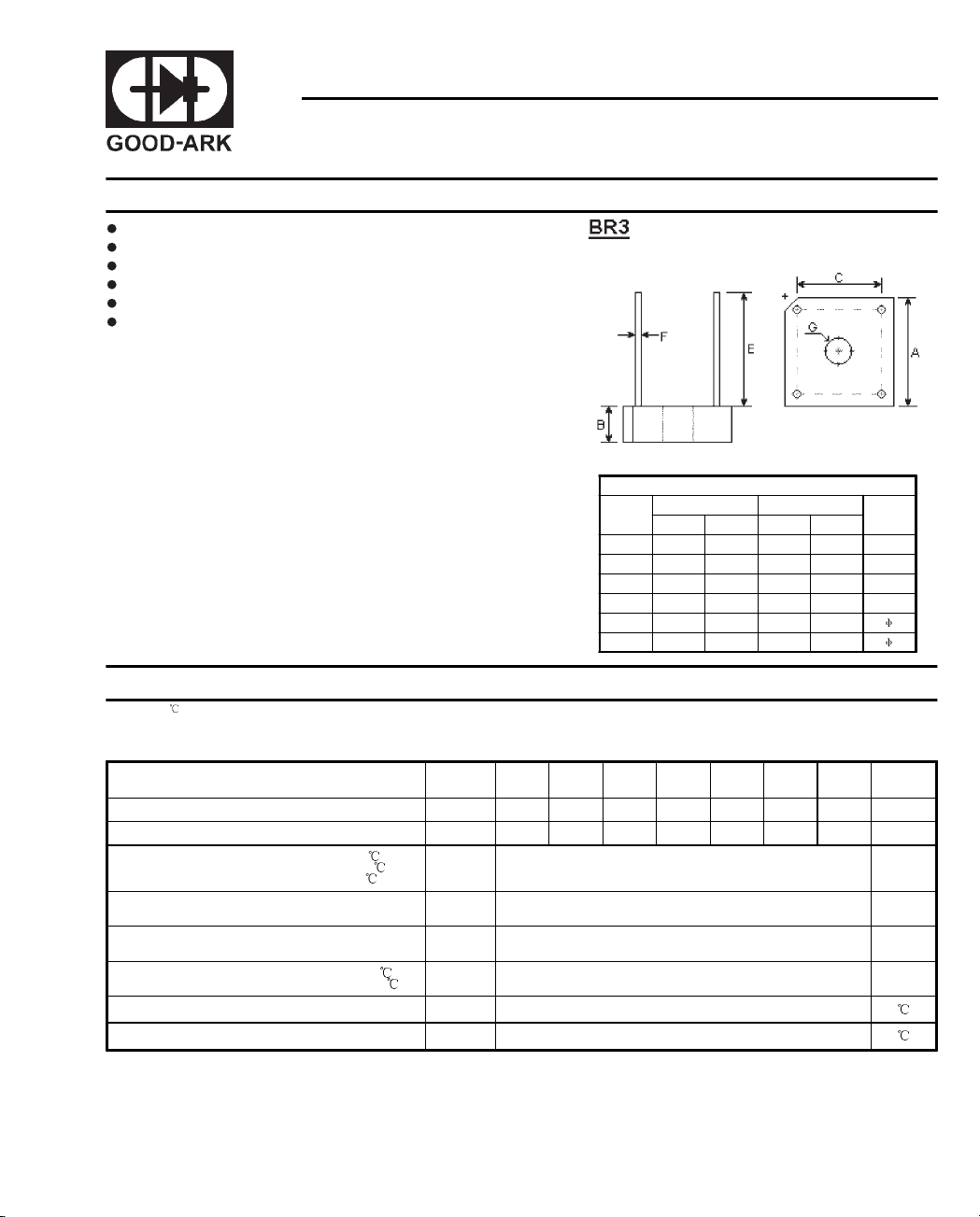
BR305 THRU BR310
SINGLE-PHASE SILICON BRIDGE
Reverse Voltage -
Forward Current -
DIMENSIONS
DIM
A 0.580 0.620 14.96 15.71
B 0.193 0.213 4.9 5.4
C 0.405 0.445 10.29 11.31
E0.75 - 19 -
F 0.028 0.032 0.71 0.81
G 0.140 0.150 3.56 3.81
inches mm
Min. Max. Min. Max.
50 to 1000 Volts
3.0 Amperes
Note
Maximum Ratings and Electrical Characteristics
Ratings at 25 ambient temperature unless otherwise specified.
Single phase, half wave, 60Hz, resistive or inductive load.
For capacitive load, derate current by 20%.
Symbols BR305 BR31 BR32 BR34 BR36 BR38 BR310 Units
Maximum repetitive peak reverse voltage V
Maximum RMS bridge input voltage V
Maximum average forward T
rectified output current at T
T
Peak forward surge current, 8.3mS single
half sine-wave superimposed on rated load
Maximum forward Voltage drop per bridge element
at 1.5A peak
Maximum DC reverse current at rated T
DC blocking voltage per element TA=100
Operating temperature range T
Storage temperature range T
Notes:
* Unit mounted on metal chassis
** Unit mounted on P.C. board
=50 *
C
=100 *
C
=50 **
A
=25
A
RRM
RMS
I
(AV)
I
FSM
V
I
R
STG
50 100 200 400 600 800 1000 Volts
35 70 140 280 420 560 700 Volts
F
J
1
3.0
2.0
2.0
50.0 Amps
1.2 Volts
10.0
1.0
-55 to +125
-55 to +150
Amps
uA
mA
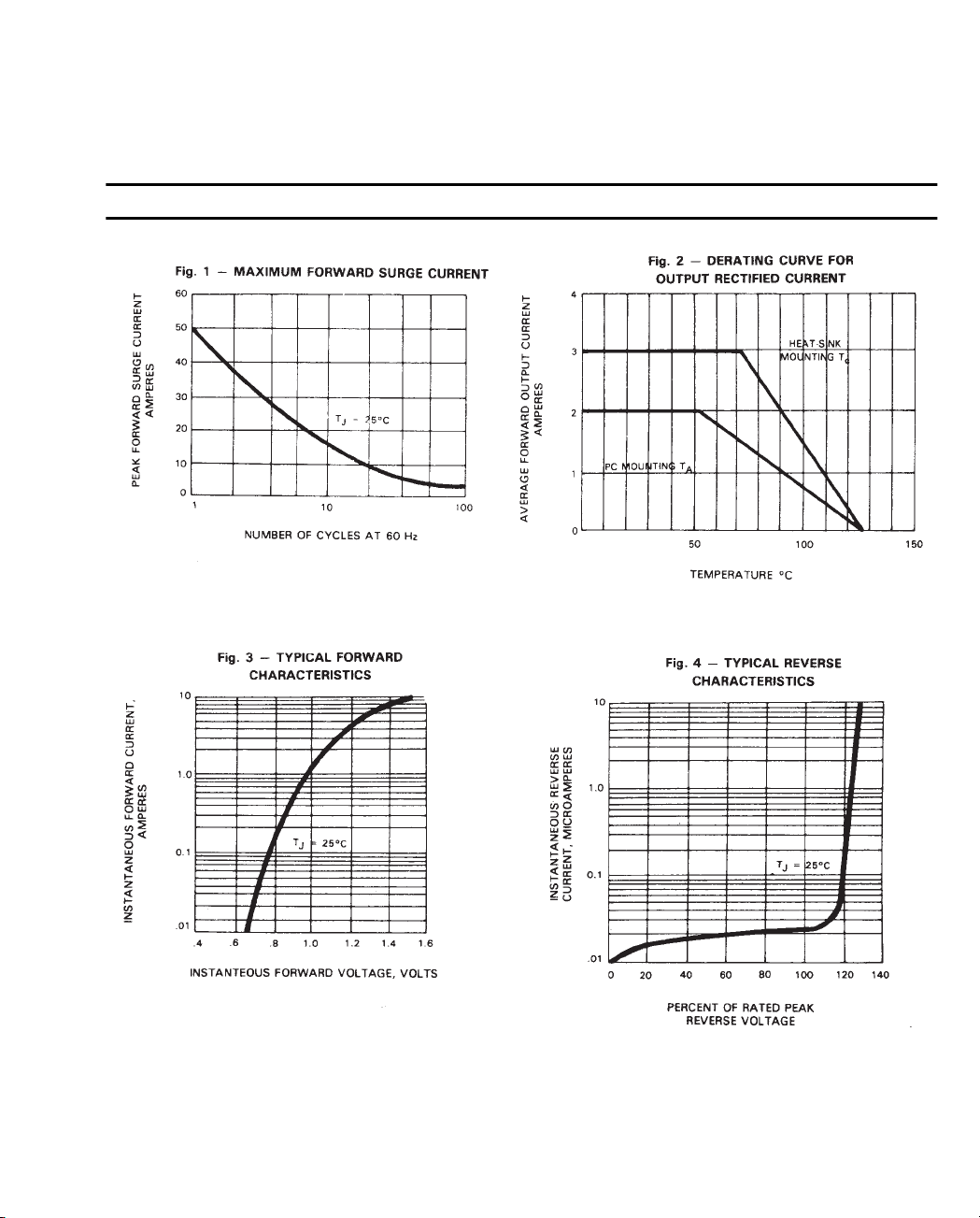
RATINGS AND CHARACTERISTIC CURVES
2
 Loading...