

GOOD-ARK 1N5281, 1N5280, 1N5279, 1N5278, 1N5277 Datasheet
...
Features
Silicon Planar Zener Diodes
Standard Zener voltage tolerance is 20%. Add suffix A
for
10% tolerance and suffix B for 5% tolerance.
Other tolerances, non standard and higher Zener voltages
upon request.
1N5221 THRU 1N5281
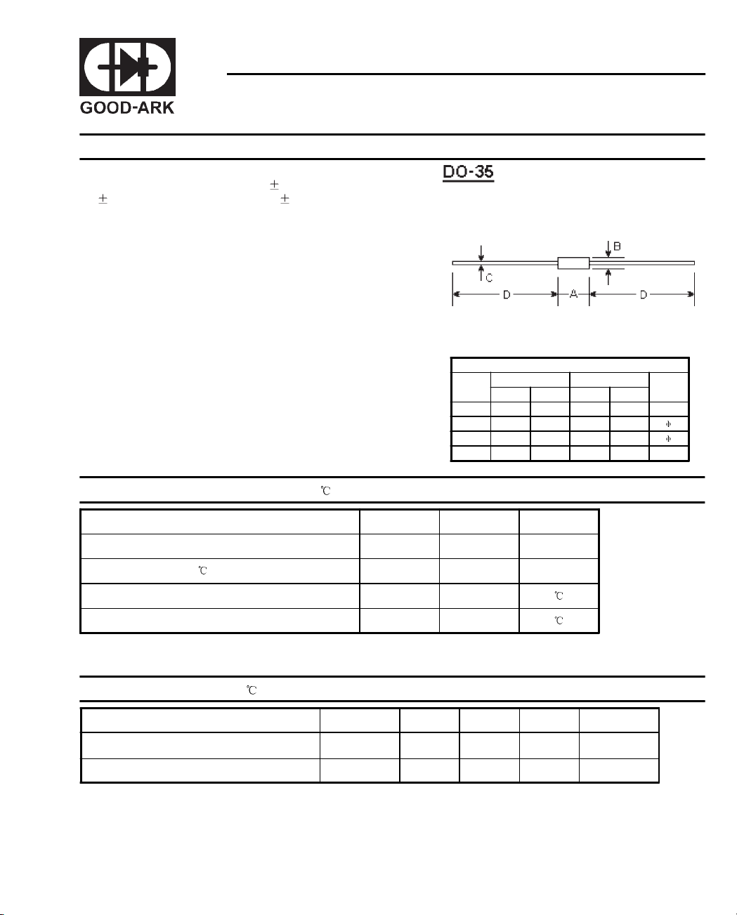
SILICON PLANAR ZENER DIODES
DIMENSIONS
DIM
A - 0.154 - 3.9
B - 0.075 - 1.9
C - 0.020 - 0.52
D 1.083 - 27.50 -
inches mm
Min. Max. Min. Max.
Note
Absolute Maximum Ratings (T
Zener current see Table "Characteristics"
Power dissipation at T
Junction temperature T
Storage temperature range T
Note:
(1) Valid provided that leads at a distance of 8 mm from case are kept at ambient temperature.
Characteristics
Thermal resistance
junction to ambient Air
Forward voltage at I
Note:
(1) Valid provided that leads at a distance of 8 mm from case are kept at ambient temperature.
=75 P
amb
T
=25
at
amb
=200mA V
F
=25 )
a
Symbols Values Units
Symbols Min. Typ. Max. Units
R
thA
F
1)
tot
j
S
500
200
-65 to +200
- - 0.3
--1.1 V
mW
1)
1
K/mW
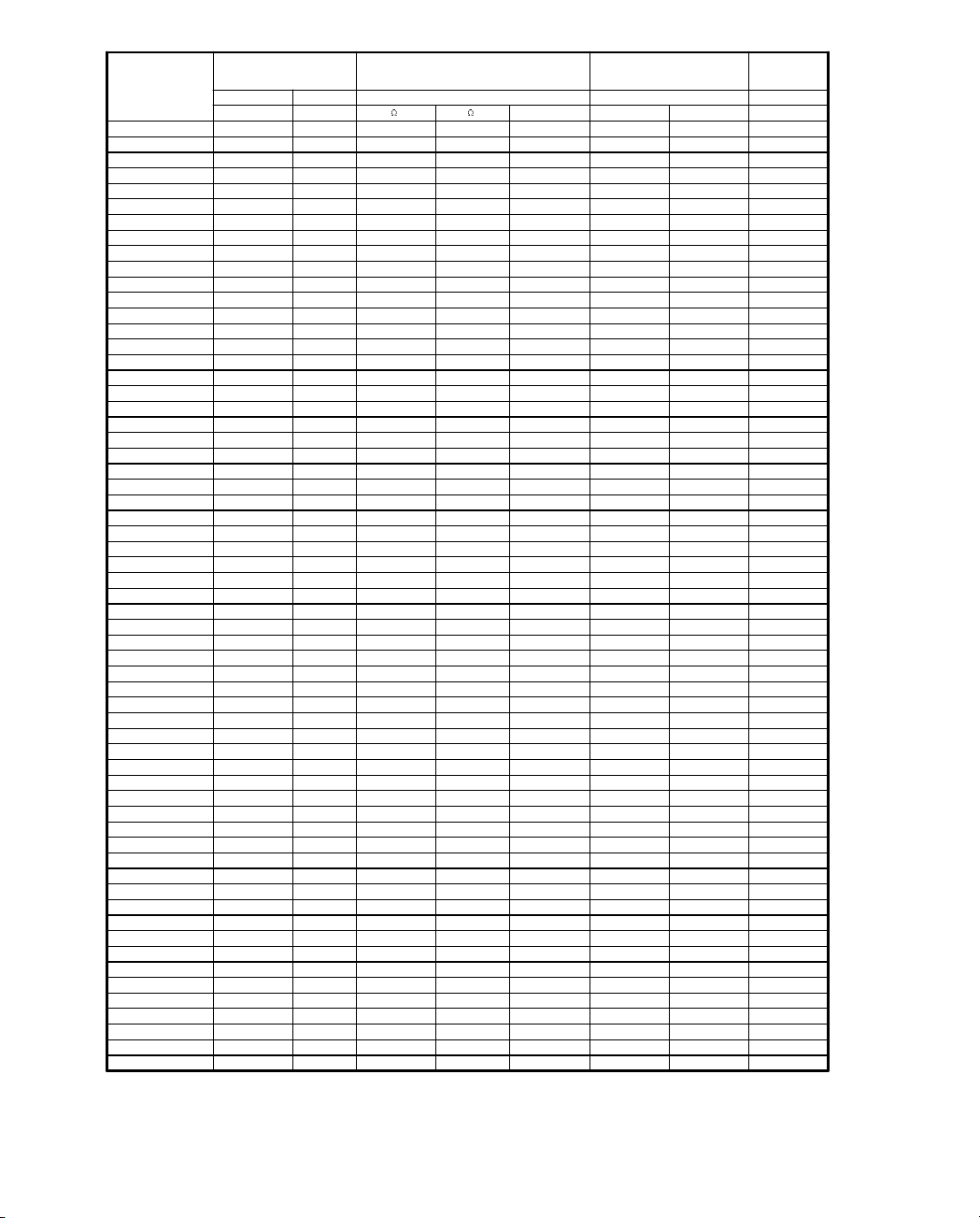
Type
Zener voltage range
3)
V
znom
VmA mA uA V % /K
1)
Maximum Zener Impedance
I
ZT
r
zjT
and r
1)
at I
zjk
zk
Reverse leakage current Temp.
IR 2) at V
R
coefficient of
Zener
voltage
TK
1N5221 2.4 20 <30 <1200 0.25 <100 1.0 <-0.085
1N5222 2.5 20 <30 <1250 0.25 <100 1.0 <-0.085
1N5223 2.7 20 <30 <1300 0.25 <75 1.0 <-0.080
1N5224 2.8 20 <30 <1400 0.25 <75 1.0 <-0.080
1N5225 3.0 20 <29 <1600 0.25 <50 1.0 <-0.075
1N5226 3.3 20 <28 <1600 0.25 <25 1.0 <-0.070
1N5227 3.6 20 <24 <1700 0.25 <15 1.0 <-0.065
1N5228 3.9 20 <23 <1900 0.25 <10 1.0 <-0.060
1N5229 4.3 20 <22 <2000 0.25 <5 1.0 <+0.055
1N5230 4.7 20 <19 <1900 0.25 <5 2.0 <+0.030
1N5231 5.1 20 <17 <1600 0.25 <5 2.0 <+0.030
1N5232 5.6 20 <11 <1600 0.25 <5 3.0 <+0.038
1N5233 6.0 20 <7 <1600 0.25 <5 3.5 <+0.038
1N523 4 6.2 20 <7 <1000 0.25 <5 4.0 < +0.045
1N523 5 6.8 20 <5 <750 0.25 <3 5.0 <+0.050
1N523 6 7.5 20 <6 <500 0.25 <3 6.0 <+0.058
1N523 7 8.2 20 <8 <500 0.25 <3 6.5 <+0.062
1N523 8 8.7 20 <8 <600 0.25 <3 6.5 <+0.065
1N5239 9.1 20 <10 <600 0.25 <3 7.0 <+0.068
1N5240 10 20 <17 <600 0.25 <3 8.0 <+0.075
1N5241 11 20 <22 <600 0.25 <2 8.4 <+0.076
1N5242 12 20 <30 <600 0.25 <1 9.1 <+0.077
1N5243 13 9.5 <13 <600 0.25 <0.5 9.9 <+0.079
1N5244 14 9.0 <15 <600 0.25 <0.1 10 <+0.082
1N5245 15 8.5 <16 <600 0.25 <0.1 11 <+0.082
1N5246 16 7.8 <17 <600 0.25 <0.1 12 <+0.083
1N5247 17 7.4 <19 <600 0.25 <0.1 13 <+0.084
1N5248 18 7.0 <21 <600 0.25 <0.1 14 <+0.085
1N5249 19 6.6 <23 <600 0.25 <0.1 14 <+0.086
1N5250 20 6.2 <25 <600 0.25 <0.1 15 <+0.086
1N5251 22 5.6 <29 <600 0.25 <0.1 17 <+0.087
1N5252 24 5.2 <33 <600 0.25 <0.1 18 <+0.088
1N5253 25 5.0 <35 <600 0.25 <0.1 19 <+0.089
1N5254 27 4.6 <41 <600 0.25 <0.1 21 < +0.090
1N5255 28 4.5 <44 <600 0.25 <0.1 21 < +0.091
1N5256 30 4.2 <49 <600 0.25 <0.1 23 < +0.091
1N5257 33 3.8 <58 <700 0.25 <0.1 25 <+0.092
1N5258 36 3.4 <70 <700 0.25 <0.1 27 <+0.093
1N5259 39 3.2 <80 <800 0.25 <0.1 30 <+0.094
1N5260 43 3.0 <93 <900 0.25 <0.1 33 < +0.095
1N5261 47 2.7 <105 <1000 0.25 <0.1 36 <+0.095
1N5262 51 2.5 <125 <1100 0.25 <0.1 39 <+0.096
1N5263 56 2.2 < 150 <1300 0.25 <0.1 43 <+0.096
1N5264 60 2.1 < 170 <1400 0.25 <0.1 46 <+0.097
1N5265 62 2.0 < 185 <1400 0.25 <0.1 47 <+0.097
1N5266 68 1.8 < 230 <1600 0.25 <0.1 52 <+0.097
1N5267 75 1.7 < 270 <1700 0.25 <0.1 56 <+0.098
1N5268 82 1.5 < 330 <2000 0.25 <0.1 62 <+0.098
1N5269 87 1.4 < 370 <2200 0.25 <0.1 68 <+0.099
1N5270 91 1.4 < 400 <2300 0.25 <0.1 69 <+0.099
1N5271 100 1.3 <500 - - <0.1 75 <+0.100
1N5272 110 1.2 <700 - - <0.1 83 <+0.100
1N5273 120 1.0 <950 - - <0.1 90 <+0.100
1N5274 130 0.95 <1100 - - <0.1 98 <+ 0.110
1N5275 140 0.90 <1300 - - <0.1 105 <+0.110
1N5276 150 0.85 <1500 - - <0.1 113 <+0.110
1N5277 160 0.80 <1700 - - <0.1 120 <+0.115
1N5278 170 0.74 <1900 - - <0.1 127 <+0.115
1N5279 180 0.68 <2200 - - <0.1 135 <+0.120
1N5280 190 0.66 <2400 - - <0.1 142 <+0.120
1N5281 200 0.65 <2500 - - <0.1 150 <+0.120
Notes:
(1) The Zener Impedance is derived from the 60Hz AC voltage which results when an AC current having an RMS value equal to 10% of the
Zener current (IZT or IZK) is superimposed on IZT or IZK. Zener Impedance is measured at two points to insure a sharp knee on the breakdown
curve and to eliminate unstable units.
(2) Valid provided that leads at a distance of 8 mm from case are kept at ambient temperature.
(3) Measured under thermal equilibrium and DC test conditions.
2
VZ
 Loading...