

GOOD-ARK 1N4763, 1N4764, 1N4762, 1N4761, 1N4760 Datasheet
...
Features
Silicon Planar Power Zener Diodes
for use in stabilizing and clipping circuits with high power
rating. Standard Zener voltage tolerance is
suffix A for
5% tolerance. Other tolerances available
upon request.
10%. Add
1N4728 THRU 1N4764
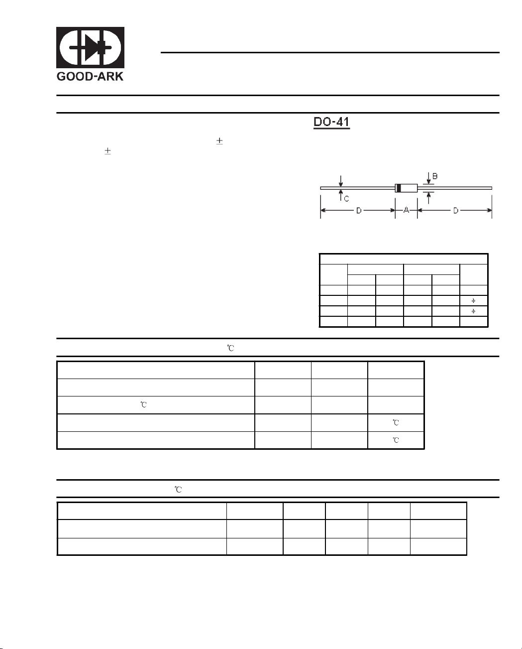
SILICON PLANAR POWER ZENER DIODES
DIMENSIONS
DIM
A - 0.169 - 4.3
B - 0.110 - 2.8
C - 0.031 - 0.8
D 1.102 - 28.0 -
inches mm
Min. Max. Min. Max.
Note
Absolute Maximum Ratings (T
Zener current see Table "Characteristics"
Power dissipation at T
Junction temperature T
Storage temperature range T
Note:
(1) Valid provided that leads at a distance of 8 mm from case are kept at ambient temperature.
Characteristics
Thermal resistance
junction to ambient Air
Forward voltage at I
Note:
(1) Valid provided that leads at a distance of 8 mm from case are kept at ambient temperature.
=25 P
amb
T
=25
at
amb
=200mA V
F
=25 )
a
Symbols Values Units
Symbols Min. Typ. Max. Units
R
thA
F
1)
tot
j
S
- - 170
--1.2 V
1
200
-65 to +200
W
1)
1
K/W
1)
at I
zjk
ZK
Reverse leakage
current
IR at V
Surge
current at
=25
T
A
R
I
R
Maximum
regulator current
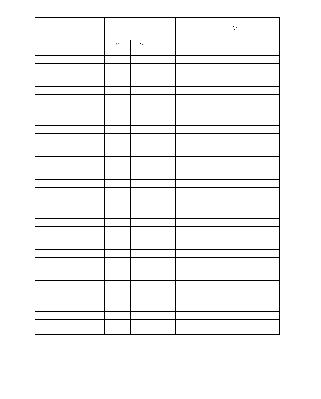
Typ e
Zener voltage
3)
range
V
znomIZT
Maximum Zener Impedance
r
and r
zjT
VmA mA uA V mA mA
1N4728 3.3 76 10 400 1.0 150 1 1375 275
1N4729 3.6 69 10 400 1.0 100 1 1260 252
1N4730 3.9 64 9 400 1.0 100 1 1190 234
1N4731 4.3 58 9 400 1.0 50 1 1070 217
1N4732 4.7 53 8 500 1.0 10 1 970 193
1N4733 5.1 49 7 550 1.0 10 1 890 178
1N4734 5.6 45 5 600 1.0 10 2 810 162
1N4735 6.2 41 2 700 1.0 10 3 730 146
1N4736 6.8 37 3.5 700 1.0 10 4 660 133
1N4737 7.5 34 4.0 700 0.5 10 5 605 121
1N4738 8.2 31 4.5 700 0.5 10 6 550 110
1N4739 9.1 28 5.0 700 0.5 10 7 500 100
1N4740 10 25 7 700 0.25 10 7.6 454 91
1N4741 11 23 8 700 0.25 5 8.4 414 83
1N4742 12 21 9 700 0.25 5 9.1 380 76
1N4743 13 19 10 700 0.25 5 9.9 344 69
1N4744 15 17 14 700 0.25 5 11.4 304 61
1N4745 16 15.5 16 700 0.25 5 12.2 285 57
1N4746 18 14 20 750 0.25 5 13.7 250 50
1N4747 20 12.5 22 750 0.25 5 15.2 225 45
1N4748 22 11.5 23 750 0.25 5 16.7 205 41
1N4749 24 10.5 25 750 0.25 5 18.2 190 38
1N4750 27 9.5 35 750 0.25 5 20.6 170 34
1N4751 30 8.5 40 1000 0.25 5 22.8 150 30
1N4752 33 7.5 45 1000 0.25 5 25.1 135 27
1N4753 36 7.0 50 1000 0.25 5 27.4 125 25
1N4754 39 6.5 60 1000 0.25 5 29.7 115 23
1N4755 43 6.0 70 1500 0.25 5 32.7 110 22
1N4756 47 5.5 80 1500 0.25 5 35.8 95 19
1N4757 51 5.0 95 1500 0.25 5 38.8 90 18
1N4758 56 4.5 110 2000 0.25 5 42.6 80 16
1N4759 62 4.0 125 2000 0.25 5 47.1 70 14
1N4760 68 3.7 150 2000 0.25 5 51.7 65 13
1N4761 75 3.3 175 2000 0.25 5 56.0 60 12
1N4762 82 3.0 200 3000 0.25 5 62.2 55 11
1N4763 91 2.8 250 3000 0.25 5 69.2 50 10
1N4764 100 2.5 350 3000 0.25 5 76.0 45 9
Notes:
(1) The Zener Impedance is derived from the 60 Hz AC voltage which results when an AC current having an RMS value
equal to 10% of the Zener current (IZT or IZK) is superimposed on IZT or IZK. Zener Impedance is measured at two points
to insure a sharp knee on the breakdown curve and to eliminate unstable units.
(2) Valid provided that leads at a distance of 8 mm from case are kept at ambient temperature.
(3) Measured under thermal equilibrium and DC test conditions.
2)
I
ZM
2
 Loading...