

Goodall Viper Owner's Manual


Viper Owner's Manual 2
Contents
1 Introduction ................................................................................................................................................... 4
1.1 About this Owner’s Manual .................................................................................................................... 4
1.2 General information ............................................................................................................................... 5
1.2.1 Loading Advice ................................................................................................................................ 5
1.2.2 Opening the Hull ............................................................................................................................. 5
1.2.3 Stability, Capsize and Recovery ....................................................................................................... 5
1.2.4 Danger from Overhead Power Lines and Other Obstacles ............................................................. 6
1.2.5 Towing on the Water ...................................................................................................................... 6
2 Assembly ....................................................................................................................................................... 7
2.1 Glossary .................................................................................................................................................. 7
2.2 Tools needed ........................................................................................................................................... 8
2.3 Arrival of goods....................................................................................................................................... 8
2.4 Platform .................................................................................................................................................. 8
2.5 Mast ...................................................................................................................................................... 14
2.6 15
2.7 Rigging .................................................................................................................................................. 15
2.8 Spinnaker pole ...................................................................................................................................... 16
3 Rigging ......................................................................................................................................................... 17
3.1 Raising / Lowering the Mast ................................................................................................................. 17
3.2 Spinnaker Pole ...................................................................................................................................... 20
3.3 Spinnaker System .................................................................................................................................. 21
3.3.1 Before Raising the Mast ................................................................................................................ 22
3.3.2 After raising the mast .................................................................................................................... 22
3.3.3 Tack line ........................................................................................................................................ 23
3.3.4 Attaching the Spinnaker ................................................................................................................ 25
3.4 Boom..................................................................................................................................................... 27
3.5 Mast Rotation ....................................................................................................................................... 27
3.6 27
3.7 Rudders ................................................................................................................................................. 28
3.7.1 Locking Down the Rudders ............................................................................................................ 29
3.7.2 Releasing the Rudders ................................................................................................................... 29
3.8 Centerboards ........................................................................................................................................ 30
3.9 Mainsail ................................................................................................................................................ 30
3.9.1 Battens .......................................................................................................................................... 30
3.9.2 Raising the Mainsail ...................................................................................................................... 32

Viper Owner's Manual 3
3.9.3 Lowering the Mainsail ................................................................................................................... 34
3.10 Jib .......................................................................................................................................................... 34
3.10.1 Jib Sheet ........................................................................................................................................ 34
3.10.2 Jib Downhaul ................................................................................................................................. 35
3.10.3 Raising the Jib ................................................................................................................................ 35
4 Sailing .......................................................................................................................................................... 37
4.1 Launching ............................................................................................................................................. 37
4.2 Recovery ............................................................................................................................................... 37
4.3 Towing on the Water ............................................................................................................................ 39
4.4 Tuning ................................................................................................................................................... 40
4.4.1 Platform......................................................................................................................................... 40
4.4.2 Rudder alignment .......................................................................................................................... 40
4.4.3 Noisy Foils ..................................................................................................................................... 41
4.4.4 Rig Tension .................................................................................................................................... 42
4.4.5 Mast rake ...................................................................................................................................... 42
4.4.6 Spreader rake ................................................................................................................................ 43
4.4.7 Diamond tension ........................................................................................................................... 44
4.4.8 Pre-bend ........................................................................................................................................ 45
4.4.9 Batten tension ............................................................................................................................... 45
4.4.10 45
4.4.11 General settings ............................................................................................................................ 46
4.5 Maintenance ......................................................................................................................................... 48
5 Systems (Diagrams) ..................................................................................................................................... 49
5.1 Cunningham ......................................................................................................................................... 49
5.2 Jib line Retrieval into Front Beam ......................................................................................................... 49
5.2.1 50
5.3 Spinnaker Halyard ................................................................................................................................ 50
5.3.1 Duel line system (With Tack Line) ................................................................................................. 50
5.3.2 Single line system .......................................................................................................................... 51
5.3.3 Under Tramp Shock Cord Layout .................................................................................................. 53
6 Warranty ..................................................................................................................................................... 54
6.1 The Full Warranty Period ...................................................................................................................... 54
6.2 Warranty conditions ............................................................................................................................. 54
6.3 Exclusions .............................................................................................................................................. 54
6.4 Operation Limitations ........................................................................................................................... 55
6.5 Limitations ............................................................................................................................................ 55
6.6 Responsibilities ..................................................................................................................................... 55
6.7 Voided Warranty .................................................................................................................................. 55

Viper Owner's Manual 4
1 Introduction
Congratulations on purchasing your new GOODALL VIPER. The VIPER is the next generation of 16
foot racing catamarans and you will soon see why. The speed and performance of the VIPER exceeds
that of the bigger catamarans. The VIPER set new standards around the world in what a “little” boat
can achieve.
Greg Goodall
Managing Director
Australian High Performance Catamarans Pty. Ltd.
1.1 About this Owner’s Manual
This manual has been compiled to help you set up and operate your VIPER catamaran safely and
easily. It contains details of the boat and its fitted equipment. Please read it carefully and familiarize
yourself with it and the boat before rigging and sailing.
You have purchased a high performance racing catamaran and as such you should ensure that you
are able to handle the catamaran in the anticipated wind and sea conditions. This owner’s manual is
not a course on boating safety or seamanship. If this is your first beach catamaran, or if your
unfamiliar with it, please ensure you obtain handling experience before “assuming command” of the
boat. Your dealer, National Sailing Federation or Yacht Club will be pleased to advise you of local
sailing schools, or competent instructors. Buoyancy aids are required for all racing events and are
recommended to wear at all times by all crew.
In some countries, a driving license or authorization may be required, or specific regulations might
apply. Please familiarize yourself with these.
This craft has been classified (in Australia) as a category C vessel, meaning a boat designed to
operate in winds up to Beaufort force 6 scale and associated wave heights.
Always maintain your boat properly and make allowance for the deterioration that will occur in time
and as a result of use. Any boat, however strong it may be, can be severely damaged if not used
properly. Please read this manual and familiarize yourself with all aspects of maintenance and care
for your boat.
Please keep this owner’s manual in a safe place and hand it over to the new owner when you sell the
boat.

Viper Owner's Manual 5
1.2 General information
Manufacturer: Australian High Performance Catamarans Pty. Ltd. (GOODALL)
Model: VIPER
Category C: “A boat designed to operate on winds up to force 6 on the Beaufort scale and associated
wave heights (significant waves up to 2 meters) Such conditions may be encountered on exposed inland
water, in estuaries and in coastal waters in moderate weather conditions.
A significant wave height is the mean height of the highest one third of the wave, which approximately
corresponds to the wave height estimated by an experienced observer. Some waves will be double this
height.”
Specifications:
Length (LH1) = 5.0 m (16.4 ft)
Width (BH1) = 2.5 m (8.2 ft)
Mast height = 8.5 m (28 ft)
Main sail area = 15 m2 (162 ft2)
Jib area = 3.7 m2 (40 ft2)
Spinnaker area = 17.5 m2 (188 ft2)
Maximum draft = 1.25 m with centre boards down
Maximum draft = 0.25 m with centre boards and rudders up
Weight fully rigged = Sloop 129 kg (284 lb)
Uni 125 kg (275 lb)
Identification: Hull identification number (HIN) on stern of each hull. Sail numbers are not always
indicative of this.
1.2.1 LOADING ADVICE
Keep the total weight of provisions, persons and miscellaneous equipment not supplied by the
manufacturer aboard below the Maximum Recommended Load and suitably distributed.
Maximum Recommended Load: x 2
+ + luggage = 200 kg.
1.2.2 OPENING THE HULL
Hatch covers in the aft deck must be sealed before leaving the shore. When storing the boat ashore,
be sure to have the holes covered but leave the hatches open for ventilation purposes.
1.2.3 STABILITY, CAPSIZE AND RECOVERY
Viper Owner's Manual 6
This boat is intended to be recovered after capsize by the crew. The minimum crew weight needed is
70 kg. See the recovery section for correct recovery technique.
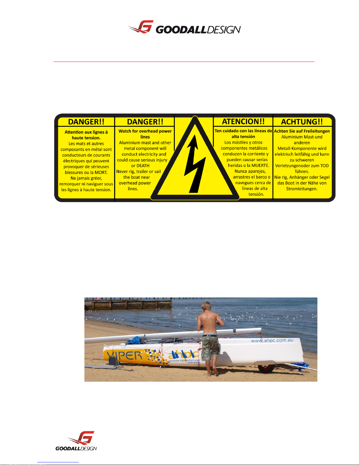
1.2.4 DANGER FROM OVERHEAD POWER LINES AND OTHER OBSTACLES
When rigging and moving your boat, please look up and inspect the overhead area. Observe the
location of overhead power lines and trees. These obstacles can damage your boat and are
potentially dangerous or deadly to yourselves.
1.2.5 TOWING ON THE WATER
When towing is required, ensure that:
- The tow rope is secured around the mast base or mast step.
- The boat is towed at a low speed.
- The tow line is fastened in such a way that it can be released quickly when under load.
- The tow line is to be of sufficient length to maneuver safely.

Viper Owner's Manual 7
2 Assembly
All GOODALL boats require minimal assembly; all parts are rigged in the factory and come almost
fully assembled so that you can be on the water as soon as possible.
Should your boat have come through a local dealer, most of the assembly has probably already been
done for you, but take this manual as a reference for building up and dismantling your VIPER when
transporting and storing.
2.1 Glossary
Aft: Back of the boat
Bow: Front of the boat
Batten: Thin rod which fits into a long narrow pocket in the sail
Bridle wire: One of the two wires connected to the bow and forestay
Boom: Spar at the foot of the sail
Centre board (Dagger Board): A retractable plate that slides vertically into each hull
Cleat: Fitting used for holding / securing ropes
Clew: Lower most after-most corner of a sail
Crossbar (Tiller): Bar that connects the rudder arms
Dolphin striker: Load bearing strap under the front beam
Downhaul (Cunningham): Control line to stretch the luff of the sail
Foot: Bottom edge of the sail
Forestay: Front wire supporting the mast
Gunwale: Top outermost edge of the hull
Goose neck: A hinge fitting connecting the boom to the mast
Halyard: Rope or wire used to hoist or lower a sail
Head: The top corner of the sail
Hound: Point where the stays are connected to the mast
Jib: Front sail
Jib Sheet: Control line for jib tension
Leeward: The side of the boat the sails are set to when sailing
Leech: Trailing edge of the sail
Luff: Front edge of the sail
Main sheet: Rope controlling the tension of the main sail
Mast rake: Angle of the mast from vertical
Mast step: Fitting where the mast is connected to the front beam

Viper Owner's Manual 8
Pintle: Fitting on the transom to attach the rudder
Rudder stock: housing of a rudder blade
Shackle: U-shaped metal strip with a pin to secure halyards etc
Shrouds (Side stay): Wire supporting the mast sideways
Spinnaker: Isometric sail hoisted when sailing downwind
Spinnaker pole: the pole between the hulls used to fly the spinnaker
Spreaders (Diamond): Metal struts placed in pairs to support the mast control the bend in the mast
Stamaster: Adjustable side stay connectors
Stern: Back of the boat
Tack: Forward lower corner of the sail
Tiller (extension): Steering stick connected to the tiller crossbar
Traveler (Car): Runs on the traveler track, which the main sheet is attached
Traveler (Track): Runs side to side on the rear beam
Transom: Flat vertical plane of the end of the hull
Trapeze: Wire to extend the body beyond the gunwale while sailing
Windward: The side of the boat opposite to where the sails are set to when sailing
2.2 Tools needed
Your VIPER parts will come from the factory pre-rigged so that it can be assembled easily, quickly and
without an expensive tool kit, but be advised to have ready with you the following tools:
- Sharp knife
- Cross head screw driver - Philips #2
- 7 mm ring spanner
- 17 mm ring spanner or preferably a hexagonal socket
- 24 mm open spanner
- Torque wrench (optional)
- Shackle tool
- Tape measure
- Duralac sealant (anti corrosive paste)
2.3 Arrival of goods
A typical delivery would typically consist of 4 packages
- 2 Long card board boxes each containing a hull.
- 1 Shorter cardboard box containing the beams, sail, boom, foils, rudder stocks etc.
- 1 Single long package for the mast, depending on shipment this may be a steel crate.
2.4 Platform
Viper Owner's Manual 9
1. Place the 2 cardboard boxes that contain the
hulls parallel on a flat surface approximately
2 meters apart and carefully cut the top open.
The sides of the boxes may be folded down
to provide a clean and protective working
surface. The packing frames inside the box
should keep the hulls upright while you work.
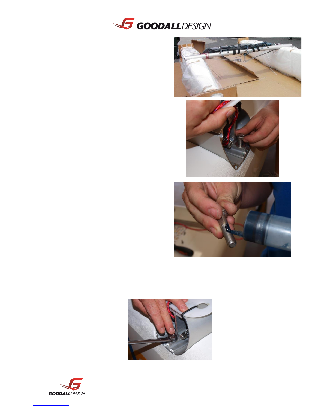
2. The beams will come from the factory pre-
rigged and ready to go onto the boat. The
shorter bolts and smaller washers are for the
outer locations and the longer bolts and
bigger washers for the inner locations. To
access the outer bolt holes you will have to
remove the plastic end caps from the beams
with a Phillips head screwdriver, don’t undo
any of the shock cords on the front beam as
they are already in the correct position.
3. Wipe all dirt and grease from the beam pad
before sitting the beam on. Make sure the
beams are facing the correct way. The rear
beam should have the traveler saddles facing
backwards. Apply grease to the threaded part
of all bolts before inserting them into the hull.
Get all the bolts started before tightening any
of the bolts. We recommend beginning with
the inner front beam bolt. If a particular bolt
is being difficult to fit. Release all the beam
bolts and fit this bolt first.
4. Use a 17 mm hexagonal socket or spanner to tighten the bolts properly. The bolts should be set to
20Nm using a torque wrench. Check the bolts regularly but in never exceed the recommended 20
Nm.

Viper Owner's Manual 10
Viper Owner's Manual 11
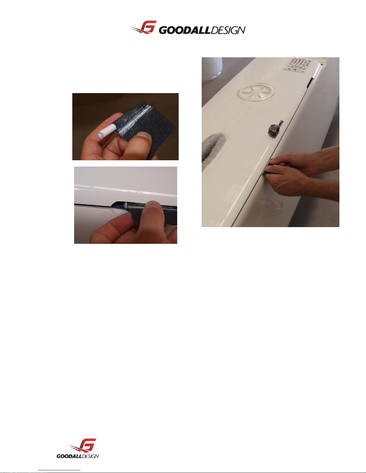
5. To reduce the risk of any sharp edges inside
the hull tracks cutting the tramp, use a small
piece of rod wrapped in sand paper (120 grit
or less) and slide the length of the track and
back to sand the inside edge of it.
6. The tramp should be pre-fitted to the front beam at the factory. If not remove the end plate from the
front beam and slide the trampoline into the front beam groove refitting the end plate once the
tramp is in place.
7. Loosen all beam bolts 2 turns; fully remove the beam bolts from one end of the front beam and
allow the bows to move closer together.
8. Insert the bolt ropes on either side into the
track of the hull. Carefully slide the
trampoline down the track on each hull. This
is best done with 1 person on either side of
the platform keeping it even on each side. It
is recommended you have someone feed the
tramp into the track while another person
pulls the tramp on.
Viper Owner's Manual 12
9. Refit the beam bolts that were removed in
step 7. You will require a 2nd person to push
the bows apart to achieve this. Then tighten
the remaining bolts to 20 N/m.
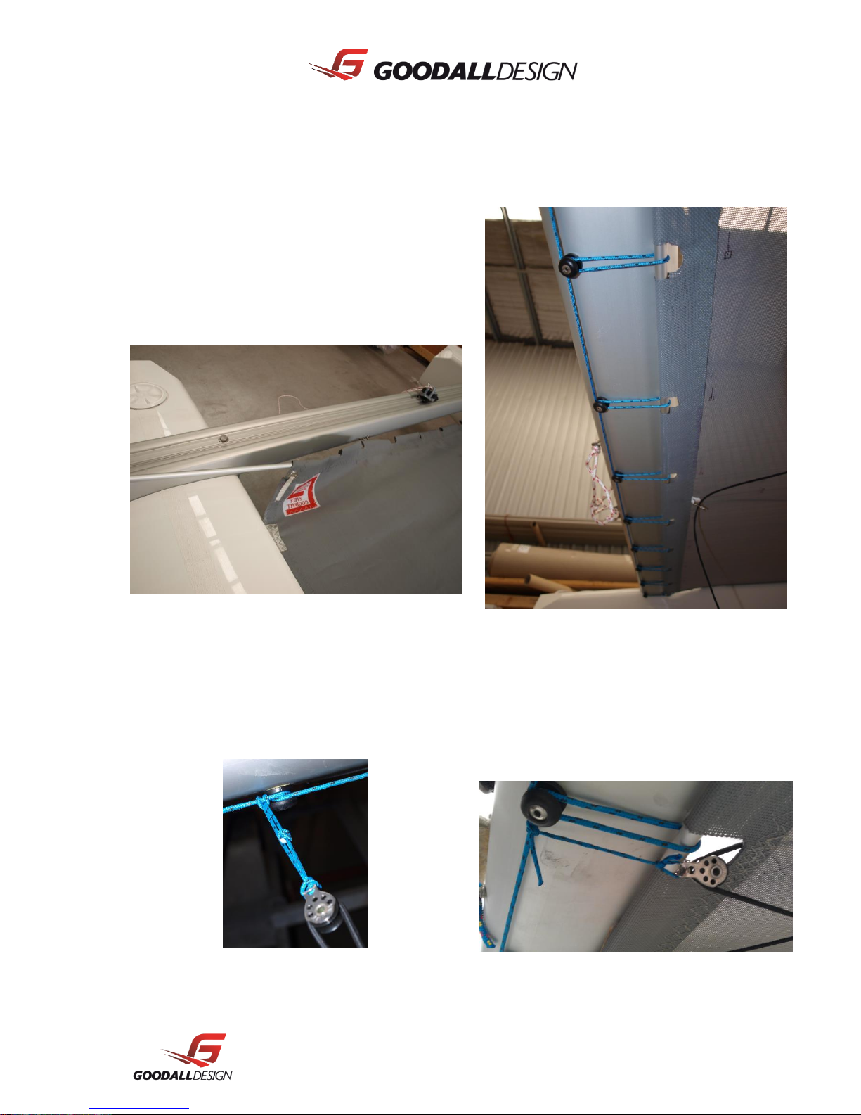
10. Slide the alloy tube into the pocket at the rear
end. Use the 3mm cord to lace the tramp to
the rope buttons on the rear beam as per the
picture. By starting at one side, tighten the
lacing as much as possible and tie at the
other end.
All cords and bungees will be pre-fitted at the
factory. Refer to the systems section of this
document for diagram.
11. Attach halyard retrieval pulleys to the lacing
before the second button in on each side.
Viper Owner's Manual 13
12. After the platform has been assembled, the
dolphin striker will need to be tensioned. Use
a 24mm spanner to extend the striker post
between the front beam and the striker strap.
The front beam should bow up in the centre
(10mm).
13. Toe straps have been provided on the
trampoline. Tie the toe straps to the saddles
on the rear beam and tighten to preference.
14. Remove the bottom half of the Stamasters
from the side stays and attach to the side
chain plates with the locknut on the inside
and the control line loop facing forward (to be
used with any control line).
15. The Continuous Cunningham system should have been already threaded from your dealer, if not,
Viper Owner's Manual 14
refers to the Systems section for a diagram.
This is also an “out to trapeze” cunning ham system. So by attaching using with the sister clip the
cunning ham will come with the crew onto trapeze.
16. Thread the mast rotation (yellow) through the tramp eye and cleat, then around the side stay.
Use the spare skippers trapeze shock cord to take up the slack
2.5 Mast
Your mast should already be fully assembled. If the mast has been shipped directly to you, some fittings may
be required to be fitted to complete the mast. All holes are predrilled and all components and rivets are
supplied. Apply Duralac or anti corrosive paste on the head of the rivet before inserting.
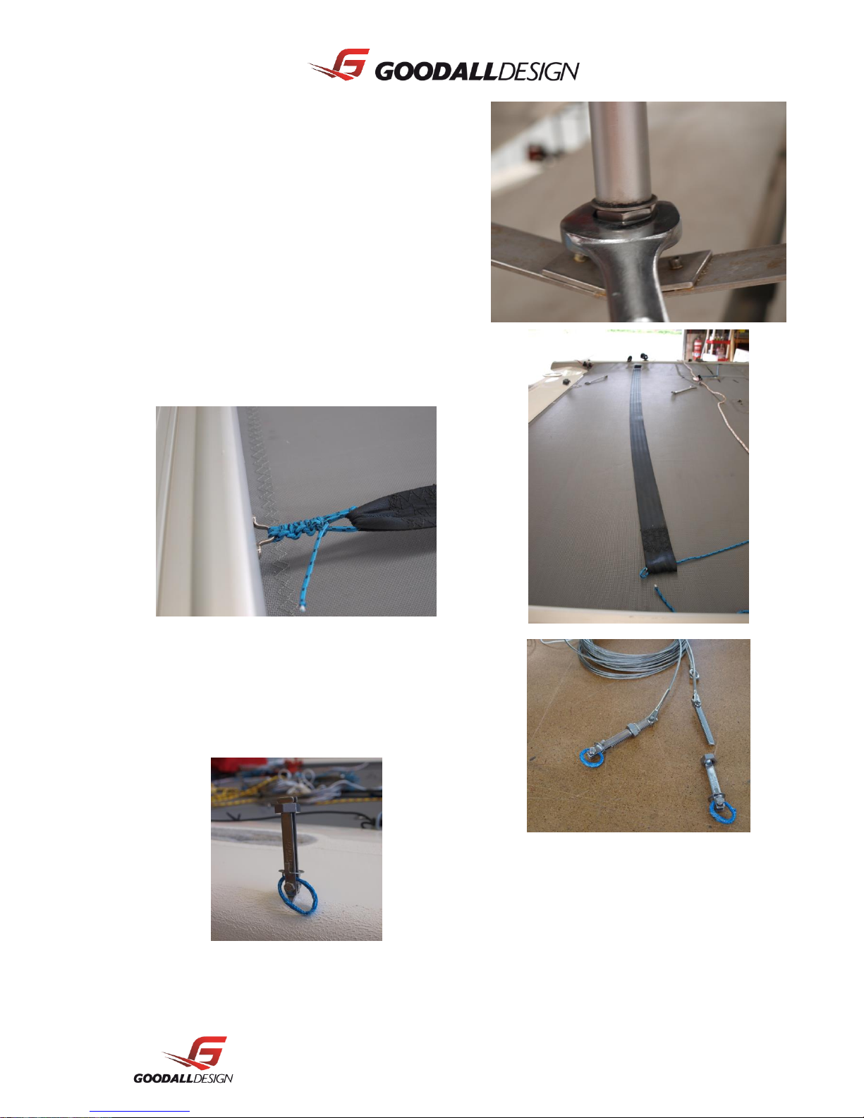
If not already fitted, fit the spreader to their
respective brackets and secure the locknuts
using a 7mm spanner. Note that the
spreaders are pre set to the factory settings.
You will notice two small dabs of epoxy on
the wires. This must be left on for reasons
that will be explained soon.
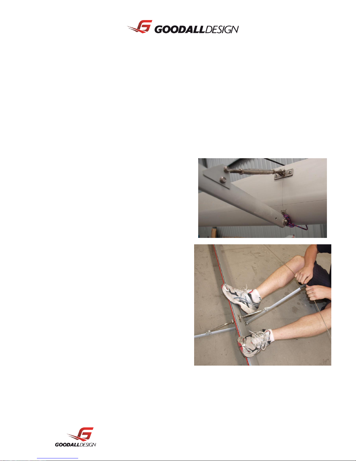
To fit the diamond wires, the mast should
lie flat. Clip the diamond arm end cap onto
the wire and put your feet at one side of the
mast at either side of the spreader. Pull the
diamond wire until it the cap slides into the
spreader. Secure it with the screw provided.
Repeat this on the other side. You will notice
this takes considerably more strength. Make
sure the spreaders are perpendicular to the
face of the mast and set the diamond
tension (in accordance with the tuning
guide) with the 17mm bolt at the bottom of
the mast base.
Viper Owner's Manual 15
All diamond wires will have a dab of epoxy
on the diamond wires both above and
below the spreader. TAPE is not suggested
as it decays in the weather and easily slips.
This prevents the spreader being knocked
out of line during capsize or spinnaker hoist
where the halyard wraps around the
spreader and pulls it up.
If the arms are out of alignment this can
case the arm to collapse and the mast to
break.
The wires will be even from the factory but you should check that the mast is straight in the sideways
direction by sighting down the sail track. If the mast has a bend this means that one diamond wire is tighter
than the other and they need to be made even. Determine which wire needs to be tightened and releasing it
from the diamond arm and the tang towards the top of the mast. Twist the whole wire clock wise while
looking from the top of the mast; this will turn the small threaded swage inside the mast base and shorten
the wire. Refit the wire to the tang and diamond arm and check for straightness. Repeat if necessary.
The mast base should never have to be removed,
but if, for some reason it does, this is the process.
Unfit both diamond wires from the
spreader arm and undo the mast base bolts
with a 10mm spanner. The base and brass
diamond adjuster block will just slide out.
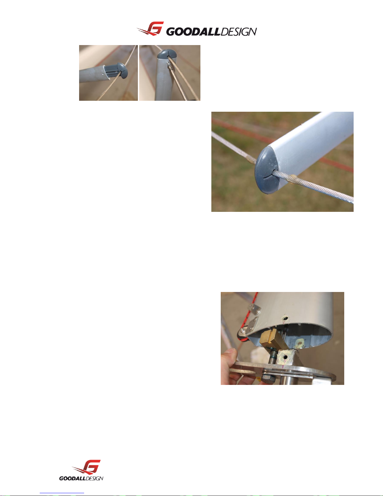
2.6 Rigging
Viper Owner's Manual 16
All rigging is fully assembled at the factory; it will simply need to be attached to the mast. The trapeze
wires attach to the upper hole on the hound fitting. The side and forestay attach to the larger lower hole.
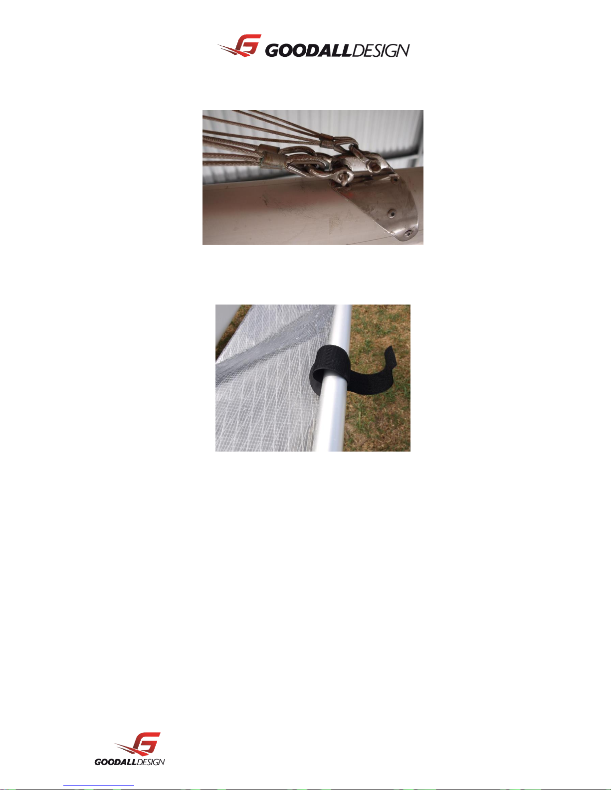
2.7 Spinnaker pole
Attach the spinnaker chute to the pole with the Velcro straps on the chute.
Viper Owner's Manual 17
3 Rigging
3.1 Raising / Lowering the Mast
When rigging and moving your boat, please look up and inspect the overhead area. Observe the
location of overhead power lines and trees. These obstacles can damage your boat and are
potentially dangerous or deadly to yourselves.
Before raising the mast you should organize your Spinnaker halyard, see below.
The usual procedure is to raise the mast from the back of the boat, however the hinged mast step
allows the mast to be raised and lowered from any direction. The key to this is that the front of the
mast must face the direction that it is to be raised from, or lowered to.
Raising the mast requires a minimum of 2 people. The usual procedure would be:
1. Put the assembled platform on a flat surface, preferably with its sterns windward.
2. Position the mast on the boat, sail track down, with the top of the mast out the stern.
 Loading...