

Goobay TV Easyslide S, TV Easyslide Twin S, TV Easyslide M, TV Easyslide Twin M User Manual [it]
Page 1
DE
EN
FR
IT
TV-Wandhalter
TV wall mount
TV Support mural
Attaco a parete per TV
BETRIEBSANLEITUNG
USER‘S MANUAL
MODE D‘EMPLOI
ISTRUZIONI PER L‘USO
63479
63480
63481
Goobay TV EasySlide S
Goobay TV EasySlide Twin S
Goobay TV EasySlide M
63482
Goobay TV EasySlide Twin M
Page 2

Betriebsanleitung
BETRIEBSANLEITUNG ............................................. 2
USER’S MANUAL ....................................................... 20
MODE D‘EMPLOI ....................................................... 38
ISTRUZIONI PER L‘USO ............................................ 56
BETRIEBSANLEITUNG
Inhalt
1 Sicherheitshinweise ................................................................... 3
1.1 Allgemeines .................................................................... 3
1.2 Benutzergruppen ............................................................4
1.3 Warnstufen .....................................................................4
2 Beschreibung und Funktion ....................................................... 5
2.1 Lieferumfang Modelle 63479 und 63480 .......................5
2.2 Lieferumfang Modelle 63481 und 63482 .......................6
2.3 benötigtes Werkzeug für alle Modelle ............................ 7
3 Bestimmungsgemäßer Gebrauch ..............................................8
3.1 Nutzungsbeschränkungen ............................................. 8
4 Montage ..................................................................................... 8
4.1 Vorbereitung ...................................................................8
4.2 Wandmontage ................................................................8
4.2.1 ...Vorbereitung ........................................................ 9
4.2.2 ...Wandmontage ................................................... 10
4.3 Flachbildschirmmontage .............................................. 11
4.3.1 ...Flachbildschirme mit acher Rückseite ............ 11
4.3.2 ...Flachbildschirme mit gewölbter Rückseite ........ 12
4.4 Einhängen und Befestigen des Flachbildschirms ........ 12
4.5 Einstellen des TV-Wandhalters .................................... 14
4.5.1 ...Einstellen des Schwenkarms ............................ 14
4.5.2 ...Einstellen der VESA-Halterung ......................... 15
4.5.3 ...Einstellen des Flachbildschirms ........................ 15
4.6 Gerätekabel verlegen ................................................... 15
5 Pege, Wartung, Lagerung und Transport .............................. 16
6 Problembehebung ................................................................... 17
7 Technische Daten ................................................................... 17
7.1 Technische Daten Modelle 63479 und 63480 .............. 17
7.2 Technische Daten Modelle 63481 und 63482 .............. 18
8 Informationen zum VESA-Standard ........................................ 18
9 Entsorgungshinweise ...............................................................19
2
Page 3

1 Sicherheitshinweise
1.1 Allgemeines
• Lesen Sie die beiliegende Produktdokumentation vollständig und sorgfältig
vor Benutzung. Diese ist Bestandteil des Produkts.
• Beachten Sie die Sicherheitshinweise in Produktdo kumentation, auf Produkt
und Zubehör, sowie auf der Verpackung.
• Benutzen Sie Produkt, Produktteile und Zubehör nur in einwandfreiem
Zustand.
• Bewahren Sie die Produktdokumentation für andere potentielle Benutzer
und zum Nachlesen auf.
• Bei Fragen, Defekten, mechanischen Beschädigungen, Störungen und
anderen nicht durch die Begleit dokumentation behebbaren Problemen,
wenden Sie sich an Ihren Händler.
Lebensgefahr durch Ersticken
Kinder können an verschluckten oder eingeatmeten Kleinteilen und Dämmmaterial ersticken.
>> Kleinteile und Dämmmaterial gegen unbeabsichtigte Benutzung sichern.
Verletzungsgefahr durch Stolpern und Sturz
Ungünstig platzierte bzw. installierte Produkte können Personen verletzen.
>> Produkt, Produktteile und Zubehör sicher platzie ren, installieren und
transportieren.
>> Bei Arbeiten mit Lasten sich und den Arbeitsort sichern und von zweiter
Person helfen lassen.
>> Demontage-, Wartungs- und Reparaturarbeiten nur von Fachpersonal
durchführen lassen.
Verletzungsgefahr durch Schneiden
Kinder können sich an Verpackungen schneiden.
>> Kleinteile und Verpackungen gegen unbeabsichtigte Benutzung sichern.
Verletzungsgefahr durch ungeeignete Umgebungsbedingungen
Extreme Umgebungsbedingungen können Personen verletzen.
>> Auf in der Wand liegende, stromführende Kabel oder andere Leitungen
achten und diese nicht beschädigen!
>> Nicht an Stellen mit direkter Sonneneinstrahlung bzw. starkem Licht
montieren. Dies fördert das Ermüden der Augen.
Verletzungsgefahr durch bewegliche Produktteile
Bewegliche Produktteile können Gliedmaßen einklemmen oder quetschen.
>> Gliedmaßen während des Gebrauchs nicht zwischen Scherteile halten.
>> Während des Gebrauchs auf die Beweglichkeit des Produktes achten.
Dieses kann sich von der Wand weg oder auf sie zu bewegen und
seitlich ausschwenken.
Gefahr durch Selbsteingriffe und Zweckentfremdung
3
Page 4
Betriebsanleitung
Selbsteingriffe und Zweckentfremdungen bergen unvorhersehbare Risiken und
führen zum Erlöschen von Gewährleistungs- und Garantieansprüchen.
>> Modizieren und ändern Sie weder Produkt, Produktteile noch Zubehör!
Sachschaden durch inkompatible Produktkombinationen
Inkompatible Produktkombinationen erfüllen nicht die gewünschte Funktion,
können Qualitätsverluste oder Sachschaden zur Folge haben.
>> Technische Daten aller verwendeter Produkte vergleichen. Diese
müssen übereinstimmen oder im angegebenen Bereich liegen.
Sachschaden durch ungeeignete Umgebungsbedingungen
Falsche Umgebungsbedingungen können Sachen beschädigen.
>> Belastungen, wie Hitze und Kälte, Nässe und direkte Sonneneinstrah-
lung sowie Vibrationen und mechanischen Druck vermeiden.
>> Um Quell- und Ausgabegeräte sowie um Schwenk- und Neigebereich
ausrei chend Platz für gute Belüftung und Beweglichkeit lassen.
Das mitgelieferte Montagematerial ist ausschließlich für die Montage an
massiven Stein- und Betonwänden geeignet.
>> Bei abweichender Beschaffenheit geeignetes Montagematerial nutzen.
>> Stabilität des Systems nach Montage regelmäßig prüfen.
1.2 Benutzergruppen
Aufgrund unterschiedlich hoher Risiken und Gefahrenpotentiale dürfen einige
Arbeitsschritte nur von geschulten Fachkräften ausgeführt werden.
Arbeitsschritt Benutzergruppe
Montage, Demontage, Ausrichten,
Pege, Lagerung,
Transport,
Entsorgung
Wartung, Reparatur
Tab. 1: Benut zergruppen
Endverbraucher und Benutzer mit mechanischen
Grundkenntnissen
>> Von Kindern und Personen mit eingeschränkten
geistigen und motorischen Fähigkeiten fernhalten
und gegen Benutzung sichern!
Geschulte Fachkräfte
>> Spezielle Sicherheitsmaßnahmen, Fachwissen und
Werkzeuge nötig!
1.3 Warnstufen
Warnung vor Gefahren, die bei Missachtung der Sicherheitshinweise
unmittel-
bar zu Tod oder schweren Verletzungen führen.
Warnung vor Gefahren, die bei Missachtung der Sicherheitshinweise zu Tod
oder schweren Verletzungen führen können.
4
Page 5
Warnung vor Gefahren, die bei Missachtung der Sicherheitshinweise zu
Verletzungen führen können.
Warnung vor Gefahren, die bei Missachtung der Hinweise zu Sachschäden
führen können.
2 Beschreibung und Funktion
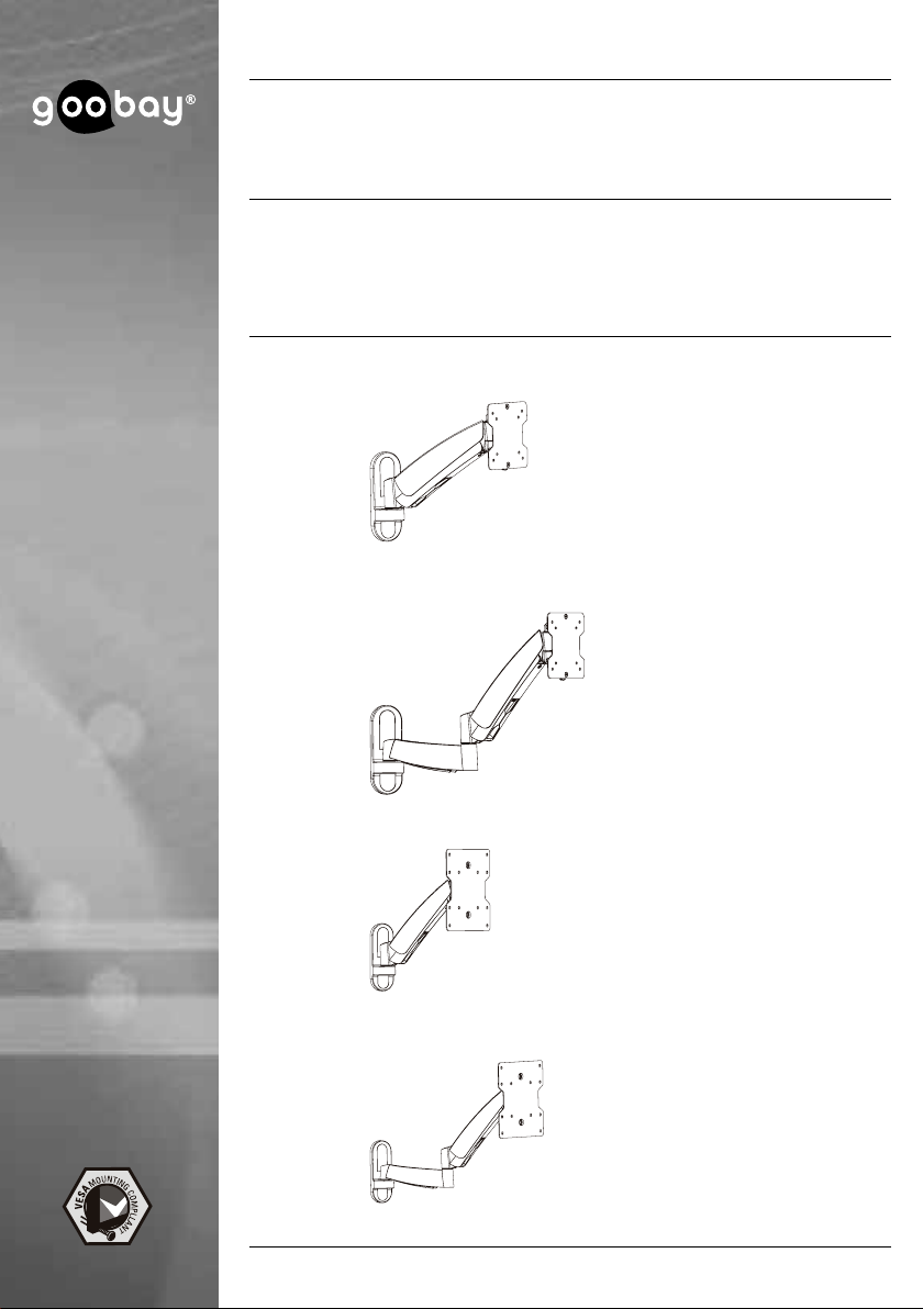
Ihr TV-Wandhalter dient der Montage Ihres Flachbildschirms an stabilen, vertikalen Wänden. Alle aufgeführten Modelle sind individuell neig- und schwenkbar
und verfügen über ein Kabelmanagementsystem.
Modelle 63479 und 63480 sind auf die Montage mit achen Flachbildschirmrückseiten beschränkt. Weiterhin sind diese für kleinere Bildschirmdiagonalen
und Gewichte ausgelegt als die Modelle 63481 und 63482.
Die Modelle 63480 und 63482 verfügen über einen doppelten Schwenkarm und
damit über eine größere Variabilität als die Modelle 63479 und 63481.
Entnehmen Sie den technischen Daten die Detailangaben zu Ihrem Modell.
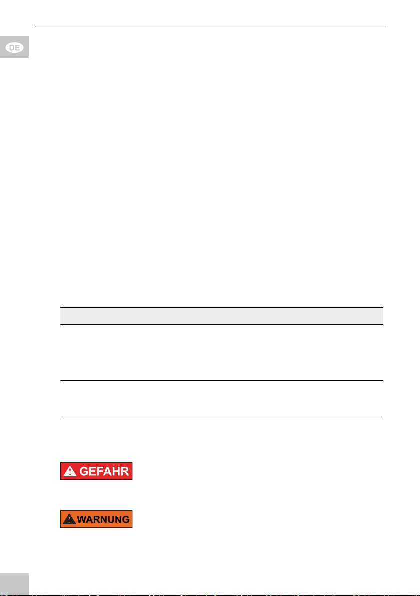
2.1 Lieferumfang Modelle 63479 und 63480
Teil Abbildung Kürzel Anzahl
Wandmontage
TV-Wandhalter mit
VESA-Platte und
Kunststoffabdeckungen
63479
oder
63480
Wandschraube 6.3x55
Betondübel
Flachbildschirmmontage
M4x14 M-A 4
M5x14
A 1
W-A 3
W-B 3
M-B 4
5
Page 6
Betriebsanleitung
Werkzeug
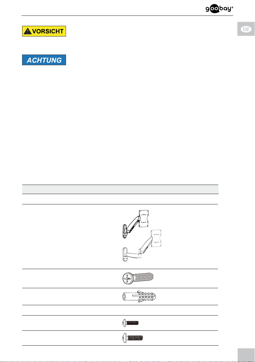
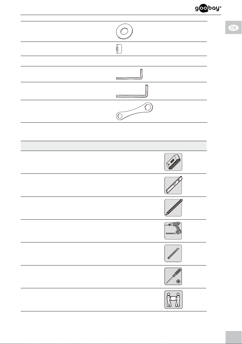
Unterlegscheibe D5 M-C 4
Innensechskant-Schlüssel
3 mm
B 1
Innensechskant-Schlüssel
6 mm
Schraubenschlüssel
Tab. 2 : Li eferumfang Mo delle 63479 und 63 480
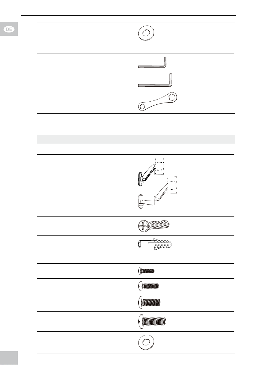
2.2 Lieferumfang Modelle 63481 und 63482
Teil Abbildung Kürzel Anzahl
Wandmontage
TV-Wandhalter mit
VESA-Platte und
Kunststoffabdeckungen
63481
oder
63482
Wandschraube 6.3x55
Betondübel
C 1
D 1
A 1
W-A 3
W-B 3
Flachbildschirmmontage
M4x14 M-A 4
M5x14
M6x14
M8x20
Unterlegscheibe D5
6
M-B 4
M-C 4
M-D 4
M-E 4
Page 7
Unterlegscheibe D8 M-F 4
TV Abstandhalter
M-G 8
Werkzeug
Innensechskant-Schlüssel
3 mm
Innensechskant-Schlüssel
6 mm
Schraubenschlüssel
Tab. 3 : Li eferumfang Mo delle 63481 und 6 3482
B 1
C 1
D 1
2.3 benötigtes Werkzeug für alle Modelle
Werkzeug Abbildung
Leitungsprüfer
Wasserwaage
Stift
Bohrmaschine
Beton-/Steinbohrer 8x60mm
Kreuzschlitz-Schraubendreher
zweite Person
Tab. 4 : be nötigtes Werk zeug für alle Mod elle
7
Page 8
Betriebsanleitung
3 Bestimmungsgemäßer Gebrauch
Dieses Produkt dient dazu, Flachbildschirme mit spezischen Bildschirmdiagonalen, Gewichten und Befestigungspunkten, die in Kapitel „technische Daten“
zusammengefasst sind, an eine vertikale Wand zu montieren. Eine andere als in
Kapitel „Beschreibung und Funktion“ beschriebene Verwendung ist nicht
gestattet. Das Nichtbeachten und Nichteinhalten dieser Bestimmungen und der
Sicherheitshinweise kann zu schweren Unfällen, Personen- und Sachschäden
führen. Beachten Sie dazu auch das Kapitel „Gewährleistung und Haftung“.
3.1 Nutzungsbeschränkungen
Nur in trockenen Innenräumen verwenden.
4 Montage
4.1 Vorbereitung
Vollständigkeit und Unversehrtheit prüfen
>> Packungsinhalt mithilfe des Lieferumfangs auf Vollständigkeit und
Unversehrtheit kontrollieren.
Kompatibilität sicherstellen
Sachschaden durch inkompatible
Produktkombinationen
>> Technische Daten aller verwendeter
Produkte vergleichen. Diese müssen übereinstimmen oder im angegebenen Bereich
liegen.
Tab. 5 : Kompatibilität sicherstellen
4.2 Wandmontage Verletzungsgefahr durch ungeeignete
Umgebungsbedingungen
>>>>Wandstruktur vor Montage überprüfen bzw.
sichere Stelle zur Montage auszuwählen.
Auf in der Wand liegende, stromführende
Kabel oder andere Leitungen achten und
diese nicht beschädigen!
>> Nicht an Stellen mit direkter Sonnenein-
strahlung bzw. starkem Licht montieren.
Dies fördert das Ermüden der Augen.
8
Page 9
Sachschaden durch ungeeignete
Umgebungsbedingungen
>> Um Quell- und Ausgabegeräte sowie um
Schwenk- und Neigbereich ausreichend
Platz für gute Belüftung und Beweglichkeit
lassen.
Tab. 6 : Wandmontage
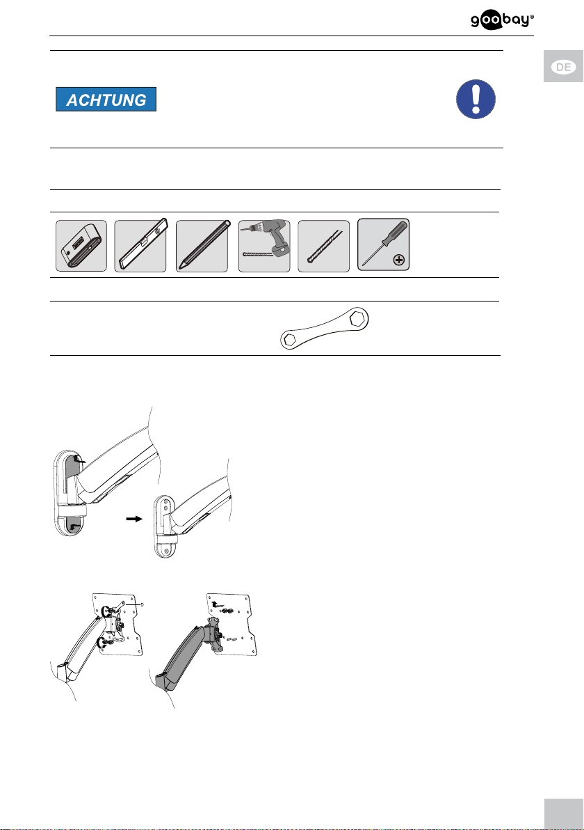
Werkzeug für alle Modelle
zusätzliches Werkzeug für Modelle 63479 und 63480
Schraubenschlüssel D
4.2.1 Vorbereitung
1. Entfernen Sie die 2 Kunststoffabde-
ckungen des TV-Wandhalters (A),
indem Sie die obere schräg nach
vorn oben und die untere nach vorn
unten schieben.
Fig. 1: Kunststoffabdeckungen entfernen
2. Entfernen Sie die VESA-Platte,
indem Sie die oberen Muttern leicht
lösen, so dass diese noch sicher auf
dem Gewinde sitzt.
3. Schrauben Sie die unteren Muttern
Fig. 2: VESA-Platte entfernen
gegen den Uhrzeigersinn vollständig
ab.
9
Page 10
Betriebsanleitung
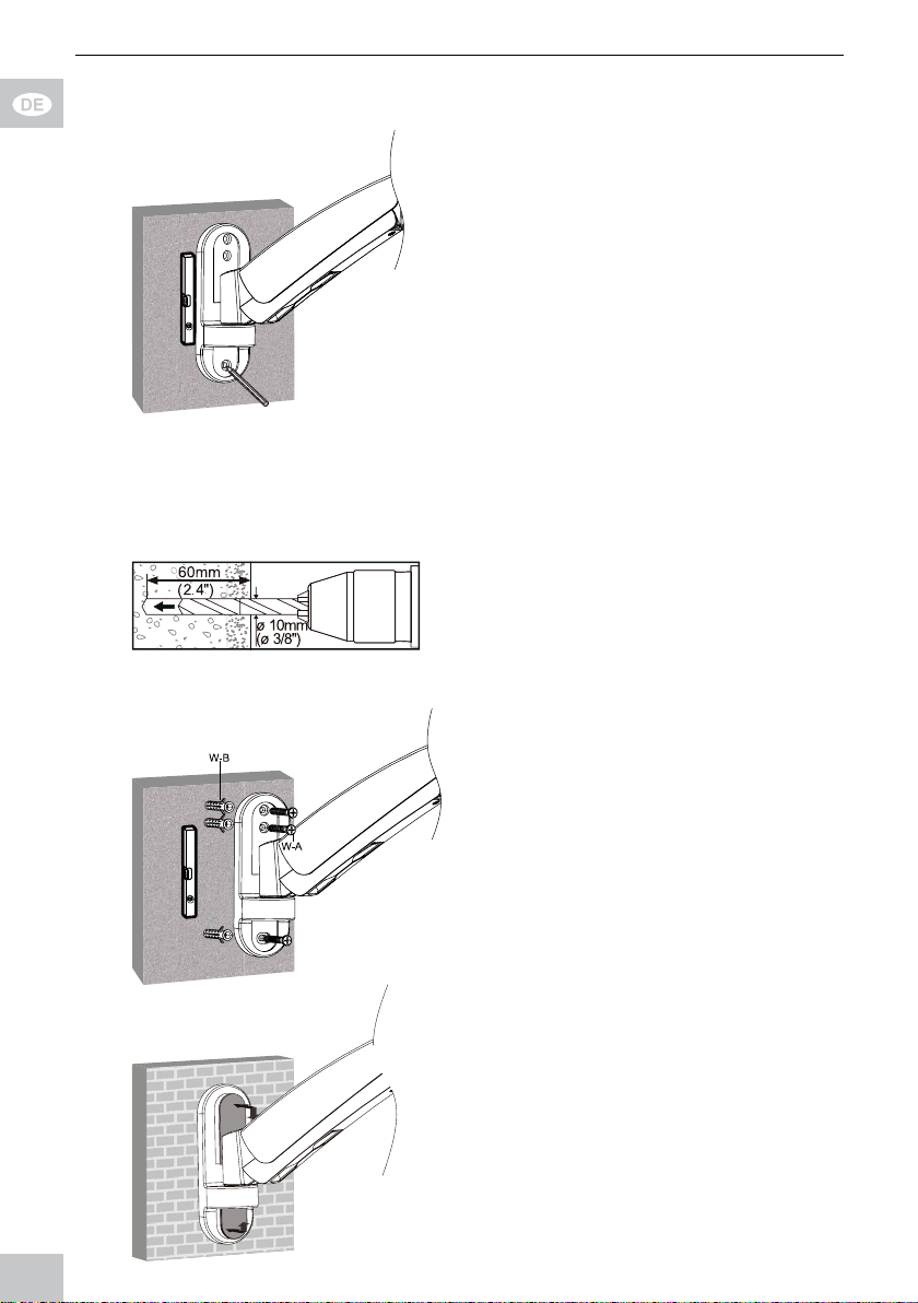
4.2.2 Wandmontage
1. Prüfen Sie vor dem Bohren, ob
sich Gas-, Wasser-, oder
Stromleitungen in der Wand
benden und beschädigen Sie
diese nicht.
2. Benutzen Sie eine Wasser-
waage, um die Bohrlöcher zu
3. Markieren Sie die Bohrlöcher
Fig. 3: Ausrichten und Anzeichnen
1 bis 3 mit einem Stift.
Der T V-Wandhalter (A) dient als
Schablone.
einem 10mm-Steinbohrer
60mm tief.
Fig. 4: Löcher bohren
markieren.
4. Bohren Sie die Löcher mit
5. Stecken Sie jeweils einen
Wanddübel (W-B) in die
Bohrlöcher.
6. Bringen Sie den TV-Wandhal-
ter (A) mit den Wandschrau-
ben (W-A) so an, dass die Ker-
be an der VESA-Plattenauf nahme nach oben zeigt.
Fig. 5: Wandmontage
7. Stecken Sie die Kunststoff-
abdeckungen wieder auf den
TV-Wandhalter (A).
10
Page 11
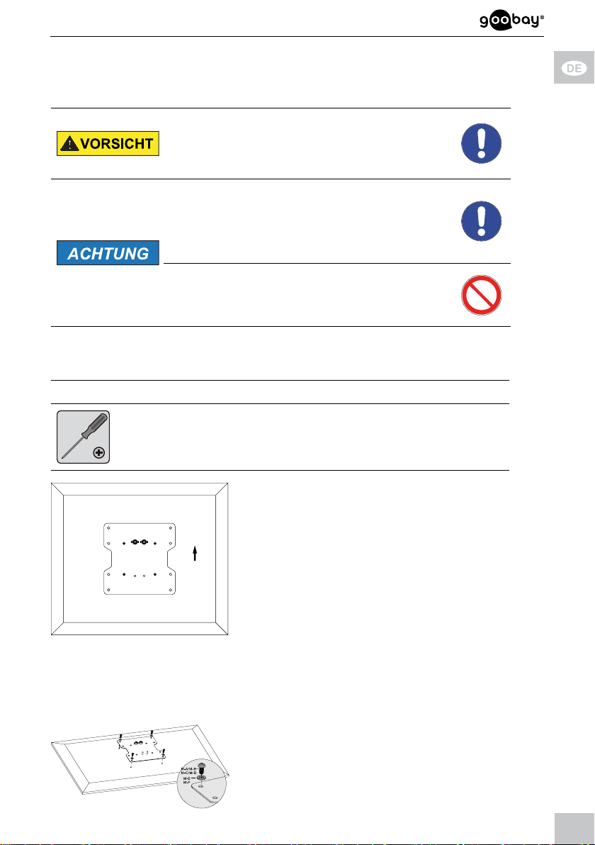
Fig. 6: Kunststoffabdecku ngen aufstecken
4.3 Flachbildschirmmontage Verletzungsgefahr durch Stolpern und
Sturz
>> Produkt, Produktteile und Zubehör sicher
platzieren, installieren und transportieren.
Sachschaden durch ungeeignete Vorgehensweise
>> Beim Anziehen von Schrauben mäßige
Kraft aufwenden, um Gewinde nicht zu
beschädigen.
>>>>Flachbildschirm NIE ach auf den Boden
legen.
Flachbildschirm nicht durch zu lange
Schrauben beschädigen.
Tab. 7: Flachbildschir mmontage
4.3.1 FlachbildschirmemitacherRückseite
Werkzeug für alle Modelle
1. Lehnen Sie den Flachbild-
schirm vertikal gegen eine
weiche, großächige Unterla-
ge oder eine Wand und
1
sichern Sie ihn gegen Kratzer
und Umkippen.
Achten Sie darauf, dass die Schrau-
ben 1 mit den vormontierten Muttern
an der Flachbildschirmoberseite
Fig. 7: A usrichtung de r VESA-Plat te 4.3.1
sitzen, wie in Kapitel 4.2 berschrie-
ben. Diese halten VESA-Platte und
Flachbildschirm beim Einhängen in
den TV-Wandhalter.
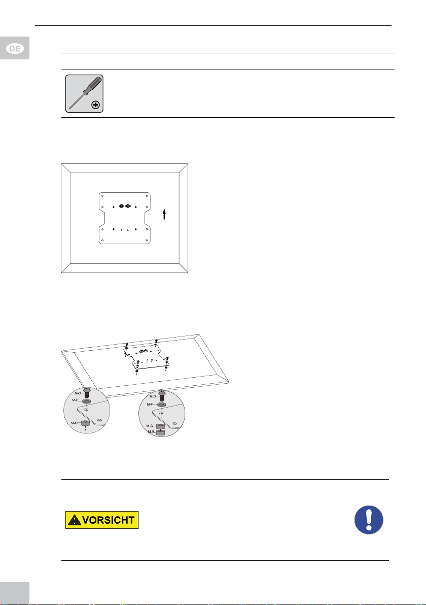
2. Montieren Sie die VESA-Platte
mit den zu Ihrem Flachbild schirm passenden Unterleg scheiben und Schrauben an
der Flachbildschirmrückseite
Fig. 8: Montage der VESA-Platte 4.3.1
wie abgebildet.
11
Page 12
Betriebsanleitung
4.3.2 Flachbildschirme mit gewölbter Rückseite
Werkzeug für alle Modelle
Die Verwendung gewölbter Flachbildschirmrückseiten ist nur mit den Modellen
63481 und 63482 möglich.
1. Lehnen Sie den Flachbild-
schirm vertikal gegen eine
weiche, großächige Unterla-
ge oder eine Wand und
sichern Sie ihn gegen Kratzer
und Umkippen.
Achten Sie darauf, dass die Schrau
ben 1 mit den vormontierten Muttern
an der Flachbildschirmoberseite
Fig. 9: Ausrichten der VESA-Platte 4.3.2
Flachbildschirm beim Einhängen in
den TV-Wandhalter.
1
sitzen, wie in Kapitel 4.2 berschrie ben. Diese halten VESA-Platte und
2. Montieren Sie die VESA-Platte
mit den Unterlegscheiben
(M-F), Schrauben (M-D) und
den TV Abstandhaltern (M-G)
an der Flachbildschirmrücksei te wie abgebildet.
Die TV Abstandhalter (M-G) können
einfach oder doppelt verwendet
Fig. 10: Montieren der VESA-Platte 4.3.2
werden. Achten Sie auf ausreichende
Schraubenlänge.
4.4 Einhängen und Befestigen des Flachbildschirms Verletzungsgefahr durch Stolpern und
Sturz
>>>>Produkt, Produktteile und Zubehör sicher
platzieren, installieren und transportieren.
Bei Arbeiten mit Lasten sich und den
Arbeitsort sichern und von zweiter Person
helfen lassen.
12
Page 13
Sachschaden durch ungeeignete Umgebungsbedingungen
>> Um Quell- und Ausgabegeräte sowie um
Schwenk- und Neigebereich ausreichend
Platz für gute Belüftung und Beweglichkeit
lassen.
Tab. 8 : Einhängen und Befestigen des Flachbildschirms
Werkzeug für alle Modelle
zusätzliches Werkzeug für Modelle 63479 und 63480
Schraubenschlüssel D
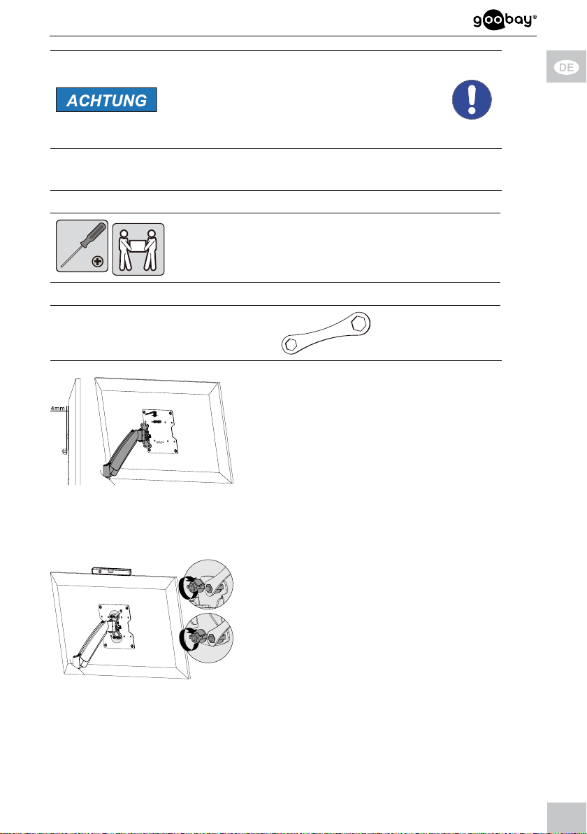
1. Hängen Sie den mit der VESA-Platte
verbundenen Flachbildschirm
den Schrauben 1 und den oberen
1
Muttern schräg auf die Kerben des
TV-Wandhalters (A).
Fig . 11: Einhängen des Flachbildschirms
Zwischen den oberen Muttern und dem
Gewindeanschlag ist ein Spalt von ca. 4mm
ideal.
zusammen mit einer 2. Person mit
1
2. Stellen Sie den Flachbild
schirm gerade.
3. Drehen Sie die oberen und
2
unteren Muttern im Uhrzeiger sinn auf die Schrauben 1 und
2, bis diese fest sitzen.
Fig. 12 : Anschrauben des Flachbildschirms
13
Page 14
Betriebsanleitung
4.5 Einstellen des TV-Wandhalters Verletzungsgefahr durch bewegliche
Produktteile
>>>>Gliedmaßen während des Gebrauchs nicht
zwischen Scherteile halten.
Während des Gebrauchs auf die Beweglichkeit des Produktes achten.
Dieses kann sich von der Wand weg oder
auf sie zu bewegen und seitlich ausschwenken.
Sachschaden durch ungeeignete Umgebungsbedingungen
>> Um Quell- und Ausgabegeräte sowie um
Schwenk- und Neigebereich ausreichend
Platz für gute Belüftung und Beweglichkeit
lassen.
Tab. 9 : Einstellen des TV-Wandhalters
4.5.1 Einstellen des Schwenkarms
Werkzeug
Innensechskant-Schlüssel
6 mm
C
Mit der 6 mm Innensechskantschraube können Sie die Federvorspannung des
Schwenkarms einstellen. Ein schwe rer Flachbildschirm benötigt eine straffere
Einstelung als ein leichter.
1. Sichern Sie mit einer Hand
den Schwenkarm.
Variante 1
Drehen Sie die 6 mm Innen sechskantschraube gegen den
Uhrzeigersinn nach (+), um die
Federvorspannung zu verstär-
ken, z.B. wenn sich der Flach-
Fig. 13: Einstellen des TV-Wandhalter
bildschirm selbstständig nach
unten bewegt.
Variante 2
Drehen Sie die 6 mm Innensechskantschraube im Uhrzeigersinn nach
(-), um die Federvorspannung zu ver ringern, z.B. wenn sich der Flach-
bild schirm selbstständig nach oben bewegt.
14
Page 15
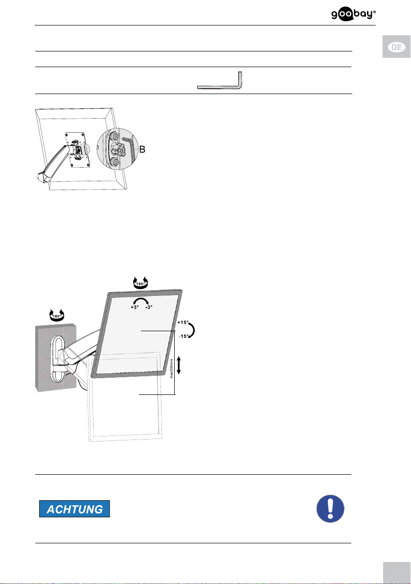
4.5.2 Einstellen der VESA-Halterung Werkzeug
Innensechskant-Schlüssel
3 mm
1. Sichern Sie mit einer Hand
den Flachbildschirm.
2. Lockern Sie die 3 mm
Innensechskantschrauben
durch Drehen gegen den
Uhrzeigersinn etwas.
3. Stellen Sie den Neigungswin-
Fig. 14: Einstellen der VESA-Halterung
kel ein.
4. Ziehen Sie die 3 mm
Innensechskantschrauben
durch Drehen im Uhrzeiger sinn wieder fest.
B
4.5.3 Einstellen des Flachbildschirms
Richten Sie den Flachbildschirm nach
Bedarf
>> vertikal,
>> horizontal und/oder
>> in der Rotationsachse aus.
Gerätekabel können aufgrund der
Beweglichkeit des TV-Wandhalters
nachträglich angeschlossen werden.
Fig. 15: Einstellen des Flachbildschirms
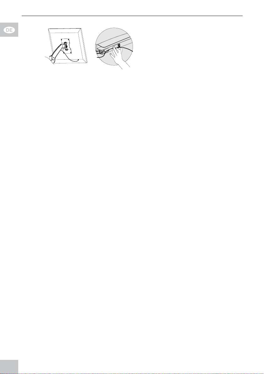
4.6 Gerätekabel verlegen
Sachschaden durch ungeeignete Umgebungsbedingungen
>> Um Quell- und Ausgabegeräte sowie um
Schwenk- und Neigebereich ausreichend
Platz für gute Belüftung und Beweglichkeit
lassen.
Tab. 1 0 : Gerätekabel verlegen
15
Page 16
Betriebsanleitung
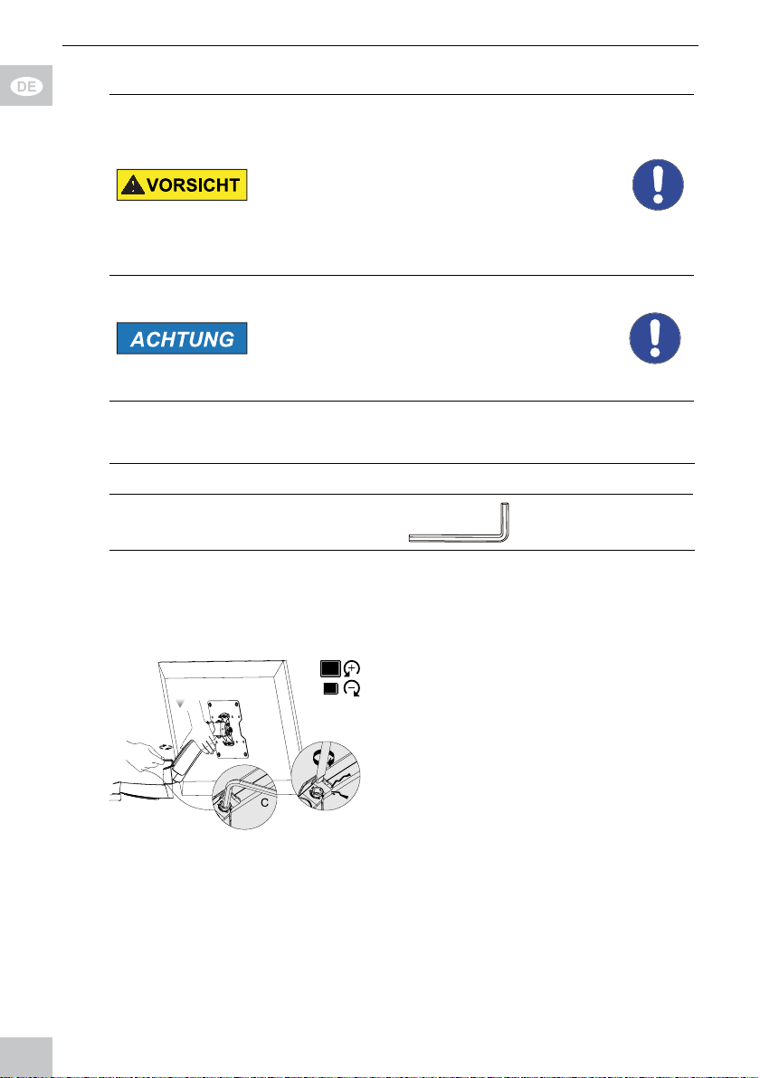
1. Schließen Sie ausreichend
lange Gerätekabel an.
2. Pressen Sie diese in die
Kabelhaltevorrichtung(en).
Fig. 16: Gerätekabel verlegen
Achten Sie auf ausreichend Spiel der
Gerätekabel, um die Beweglichkeit
des Systems zu gewährleisten.
Ende der Montage. Zur Demontage gehen Sie in rückwärtiger
Reihenfolge vor.
5 Pege,Wartung,LagerungundTransport
• Das Produkt darf nur von einer Fachwerkstatt gewartet werden.
• Schützen Sie die Gelenke vor Schmutz und schmieren Sie diese regelmäßig
mit leichtem Maschinenöl.
• Reinigen Sie es nur mit einem trockenen, weichen Tuch. Gehen Sie beim
Reinigen vorsichtig vor, um Kratzer zu vermeiden. Bei starken Verschmut zungen kann das Reinigungstuch leicht mit Wasser angefeuchtet werden.
Setzen Sie keine Reini gungsmittel oder Chemikalien ein, da dies das
Material angreifen kann.
• Achten Sie beim Bewegen der Geräteteile darauf, dass Sie keine Körperteile
darin einklemmen!
• Kontrollieren Sie regelmäßig alle Befestigungen und Schrauben auf festen
Sitz und ziehen Sie diese bei Lockerung wieder fest. Wenden Sie aber nicht
zu viel Kraft an, um die Gewinde nicht zu überlasten.
• Vermeiden Sie Stellen mit hohen Temperaturen und Feuchtigkeit, bzw.
Stellen, die nass werden können, auch bei Wartung, Pege, Lagerung und
Transport.
• Lagern Sie Ihr Produkt bei längerem Nichtgebrauch für Kinder unzugänglich
und in trockener und staubgeschützter Umgebung.
• Befestigungsbohrungen können sichtbar bleiben, wenn das Produkt demon-
tiert wird. Nach längerem Gebrauch kann ein Fleck auf dem Untergrund
zurückbleiben.
• Heben Sie die Originalverpackung für den Transport auf, um Schäden zu
vermeiden.
16
Page 17
6 Problembehebung
Problem Hilfe
Verkehrslasten für Wohnräume sind in diversen Europa-
Wie kann die
Wandqualität
getestet werden?
richtlinien festgelegt.
>>
Wandstärke und Material unter Putz / Tapeten
prüfen.
Fachpersonal zu Rate ziehen.
>>
Welche Löcher
müssen gebohrt
>> Kapitel 4.2 lesen.
werden?
Der T V-Wandhalter lässt sich
>> Die maximale Schwenkbarkeit kann bedingt durch
die TV Größe kleiner sein, als angegeben.
schwer ausrichten.
Der T V-Wandhalter macht
Geräusche
>>>>Diese resultieren aus der innenliegenden Feder und
sind während des Bewegens normal.
Treten diese im Ruhezustand auf, lesen Sie Kapitel
4.5.1.
andere Fragen >> Händler kontaktieren.
Tab. 11 : Problembehebung
7 Technische Daten
7.1 Technische Daten Modelle 63479 und 63480
Größe Angabe Einheit
TV Größe 13 -27 “ / Zoll
VESA 75x75 / 100x100 mm
Trag l ast max. 15 kg
Neigungswinkel +/-15 °
Schwenkwinkel
der VESA-Platte
Schwenkwinkel
je Schwenkarm
Rotationswinkel
der VESA-Platte
Wandabstand
Maße
Gewicht
Tab. 12 : Technisc he Daten Modelle 6 3479 und 6348 0
+/-90 °
+/-90 °
+/-2 °
63479: 50 -360
63780: 55-580
63479: 132 x 475 x 50-360
63480: 132 x 475 x 55-580
63479: 2,40
63480: 2,95
mm
mm
kg
17
Page 18
Betriebsanleitung
7.2 Technische Daten Modelle 63481 und 63482
Größe Angabe Einheit
TV Größe 17- 42 “ / Zoll
VESA 100x100 / 200x100 / 200x200 mm
Trag l ast max. 20 kg
Neigungswinkel +/-15 °
Schwenkwinkel
der VESA-Platte
Schwenkwinkel
je Schwenkarm
Rotationswinkel
der VESA-Platte
Wandabstand
Maße
Gewicht
Tab. 13 : Tec hnische Daten Mo delle 63481 und 6 3482
+/-90 °
+/-90 °
+/-3 °
63481: 55-360
63782: 55-580
63481: 230 x 565 x 55 -360
63482: 230 x 565 x 55-580
63481: 3,26
63482: 3,84
mm
mm
kg
8 Informationen zum VESA-Standard
Um die Befestigungsmöglichkeiten von Monitoren, TV-Geräten und deren
Ständer und TV-Wandhalter benutzerfreundlich zu vereinheitlichen, hat die
VESA (Video Electronic Standard Association) für die oben genannten Anwendungen 3 Standards festgelegt. Mit Hilfe des auf Ihrem Anzeigegerät oder in
dessen Betriebsanleitung stehenden jeweiligen VESA-Standards und den
technischen Daten in dieser Anleitung können Sie die möglichen Befestigungspunkte denieren. Einige Modelle lassen eine stufenlose, individuelle Befestigung zu.
(z.B. 300 x 300mm für Sony TVs).
VESA Klasse Befestigungslochabstand von Flachbildschirmen
MIS-D 75x75 / 100x100mm
MIS-E 200x100 / 200x200mm
MIS-F 400x200 / 400x400 / 600x200 / 600x400 / 800x400mm
Tab. 14 : Informationen zum VESA-Standard
18
Page 19

9 Entsorgungshinweise
Dieses Produkt gehört nicht in den Hausmüll. Bitte geben Sie Ihr Gerät am Ende
seiner Lebensdauer an die dafür eingerichteten, öffentlichen Sammelstellen oder an
die Verkaufsstelle kostenlos zurück. Einzelheiten zur Entsorgung regelt das jeweilige
Landesrecht. Wertstoffe werden dem Recyclingkreislauf zugeführt, um daraus neue
Rohstoffe zu gewinnen. Folgende Wertstoffe werden in kommunalen Sammelstellen
gesammelt:
• Altglas, Kunststoffe, Altmetalle, Bleche uvm.
Mit dieser Art der Verwertung von Altgeräten leisten Sie einen wichtigen Beitrag zum
Schutz unserer Umwelt.
19
Page 20

User‘s Manual
BETRIEBSANLEITUNG ............................................. 2
USER’S MANUAL
MODE D‘EMPLOI
ISTRUZIONI PER L‘USO
....................................................... 18
....................................................... 32
............................................ 48
USER’S MANUAL
Content
1 Safety Instructions ................................................................... 21
1.1 General Notes ..............................................................21
1.2 User Groups .................................................................22
1.3 Warning Levels ............................................................. 22
2 Description and Function ......................................................... 23
2.1 Scope of Delivery for Models 63479 and 63480 ..........23
2.2 Scope of Delivery for Models 63481 and 63482 ..........24
2.3 Required tools for all Models ........................................ 25
3 Intended Use ............................................................................25
3.1 Use restrictions .............................................................26
4 Installing ................................................................................... 26
4.1 Preparing ...................................................................... 26
4.2 Wall mounting ...............................................................26
4.2.1 ...Preparing ...........................................................27
4.2.2 ...Wall mounting .................................................... 27
4.3 Mounting the at screen ............................................... 28
4.3.1 ...Flat screens with at back ................................. 28
4.3.2 ...Flat screens with arched back ..........................29
4.4 Attaching and fastening the at screen ........................ 30
4.5 Adjusting the at screen ............................................... 31
4.5.1 ...Adjusting the swivel arm ................................... 31
4.5.2 ...Setting the VESA plate ...................................... 32
4.5.3 ...Adjusting the at screen .................................... 32
5 Maintenance, Care, Storage and Transport ............................ 33
6 Troubleshooting .......................................................................33
7 Specications...........................................................................33
7.1 Specications of Models 63479 and 63480 .................34
7.2 Specications of Models 63481 and 63482 .................34
8 Information for VESA standard ................................................ 35
9 Disposal Instructions ...............................................................35
20
Page 21

1 Safety Instructions
1.1 General Notes
• Read the including product documentation completely and carefully before
use. It is part of the product.
• Attend to the safety instructions in product documentation, on product and
accessories, such as on the package.
• Use product, product parts and accessories only in perfect condition.
• Keep the product documentation for other potential users and for later
requests.
• For questions, defects, mechanical damage, disturbances and other not
remediable problems, consult your dealer.
Risk of life by suffocating
Children can suffocate by swallowed or inhaled parts and insulation materials.
>> Protect small parts and insulation material against unintentionally use.
Risk of injury by tripping and falling
Unfavorable placed or installed products and cable connections can injure
persons.
>> Place, transport and install product, parts and acceories in a safe way.
>> When working with burdens, secure yourself and the working place, let a
second person help you.
>> Let only a specialist do disassembly, maintenance and repair work.
Risk of injury by cutting
Children can cut themselves on packaging materials.
>> Protect packaging materials against unintentionally use.
Risk of material damage by improper product combination
Incompatible product combination does not fulll required functions, can cause
quality losses or material damage.
>> The specications of all used products must match or be within the
specied range.
Risk of injury by inappropriate ambient conditions
Extreme conditions can injure persons.
>> Attend to live cables or other lines lying behind plaster, and do not
damage them!
>> Do not install the product to places with direct sunlight or bright light.
This contributes to eye fatigue.
Risk of injury by moving product parts
Moving product parts can pinch or squeeze limbs.
>> Do not hold limbs between shear parts during use.
>> Mind the mobility of the product during use. This may move away from
the wall or towards it and swivel sideways.
Risk of self-intervention and misuse
21
Page 22
User‘s Manual
Self-interventions and misuse hide unpredictable risks and cause expiration of
warr anty.
>> Do not modify or alter either the product or the accessories!
Risk of material damage by inappropriate ambient conditions
Incorrect ambient conditions can damage things.
>> Avoid extreme conditions, such as extreme heat, coldness, humidity or
direct exposure to the sun, as well as vibrations and mechanical pressure.
>> Keep enough space around product and to the whole system to ensure
proper ventilation and mobility.
The included mounting material is only suitable for mounting on massive stone
or concrete walls.
>> For other wall types use suitable mounting material.
>> Check the stability of the system periodically after installation.
1.2 User Groups
Caused to different risk levels and hazard potentials some working steps only
may be done by trained specialists.
Working step User Group
Installing,
Uninstalling,
Aligning, Care,
Storage, Trans-
Consumers and users with basical mechanical knowledge
can do this work.
>> Protect children and people with mental and motoral
impairments from using the product!
port, Disposal
Maintenance,
Repairing
Trained specialists only
>> special safety measures, knowledge and tools are nec-
essary!
Tab. 1 5 : User Groups
1.3 Warning Levels
Warnings against hazards that will result directly in serious injuries or death
in case of non-observance.
Warnings against hazards that may result in serious injuries or death in case
of nonobservance.
Warnings against hazards that may result in injuries in case of non-observance.
Warnings against hazards that may result in material damage in case of
non-observance.
22
Page 23

2 Description and Function
Your TV wall mount is used for mounting your at screens to secure and vertical
walls. All models listed are individually tiltable and swivelable and feature a
cable management system.
Models 63479 and 63480 are limited to at screen mounting with at backs.
Furthermore, these are designed for smaller screen sizes and weights than the
models 63481 and 63482.
Models 63480 and 63482 have a double swivel arm and thus have a greater
variability than the models 63479 and 63481.
Refer to the specications for details of your model.
2.1 Scope of Delivery for Models 63479 and 63480
Part Figure Symbol Amount
Wall mounting
TV wall mount with
VESA plate and
plastic covers
63479
or
63480
Wall screw 6.3x55
Concrete anchor
Flat screen mounting
M4x14 M-A 4
M5x14
Washer D5
Tools
Allen key
3 mm
A 1
W-A 3
W-B 3
M-B 4
M-C 4
B 1
23
Page 24

User‘s Manual
Allen key
6 mm
Wrench
Tab. 1 6 : Sc ope of Deliver y for Models 63 479 and 63480
2.2 Scope of Delivery for Models 63481 and 63482
Part Figure Symbol Amount
Wall mounting
TV wall mount with
VESA plate and
plastic covers
63481
or
63482
Wall screw 6.3x55
Concrete anchor
C 1
D 1
A 1
W-A 3
W-B 3
Flat screen mounting
M4x14 M-A 4
M5x14
M6x14
M8x20
Washer D5
Washer D8
TV Spacer
24
M-B 4
M-C 4
M-D 4
M-E 4
M-F 4
M-G 8
Page 25

Tools
Allen key
3 mm
Allen key
6 mm
Wrench
Tab. 17: Sc ope of Deliver y for Models 63 481 and 63482
B 1
C 1
D 1
2.3 Required tools for all Models
Tool Figure
Line tester
Spirit level
Pencil
Phillips screwdriver
Drilling mashine
Concrete drill 8x60mm
Second person
Tab. 1 8 : Required tools for all Models
3 Intended Use
This product is made for mounting at screens with specic screen sizes,
weights and mounting points, which are summarized in chapter “Technical data“,
on a vertical wall. Another use than described in chapter “Description and
25
Page 26

User‘s Manual
Function“ is not permitted. Neglegting and ignoring these regulations and safety
instructions can cause serious accidents, personal injury and material damage.
Also refer to chapter “Warranty and Liability“.
3.1 Use restrictions
Only use in dry interior rooms.
4 Installing
4.1 Preparing
Checking the completeness and integrity
>> Check the packing content by comparing it to the scope of delivery
regarding completeness and integrity.
Ensuring compatibility
Risk of material damage by improper
product combination
>> The specications of all used products must
match or be within the specied range.
Tab. 1 9 : Ensuring compatibilit y
4.2 Wall mounting
Risk of injury due to inappropriate
ambient conditions
>>>>Check the wall structure before installing
or choose a safe installation place.
Attend to live cables or other lines lying
behind plaster, and do not damage them!
>> Do not install the product to places with
direct sunlight or bright light. This contributes to eye fatigue.
Risk of material damage by inappropriate ambient conditions
>> Keep enough space around product and
to the whole system to ensure proper
ventilation and mobility.
Tab. 2 0 : Wall mounting
Tools for all Models
26
Page 27

additional tools for Models 63479 and 63480
Wrench D
4.2.1 Preparing
1. Remove the 2 plastic covers of the
TV wall mount (A) by sliding the
upper one obliquely forward and
upward and the lower one forward
and downward.
Fig. 17: Removing the p lastc covers
2. Remove the VESA plate by loosening
the top nuts slightly, so that they are
still tting securely on the thread.
3. Remove the lower nuts counterclock-
wise and completely.
Fig. 18: Removi ng the VESA plate
4.2.2 Wall mounting
1. Before drilling, attend to live cables or
other lines lying behind plaster, and
do not damage them.
2. Use a spirit level to mark the drill
holes on the wall.
3. Mark the drill holes 1 to 3 with a
pencil.
Use the TV wall plate (A) as template.
Fig. 19: Aligning and marking
4. Drill the drill holes with a 10mm
concrete drill 60mm deep.
Fig. 20: Drilling drill holes
27
Page 28

User‘s Manual
5. Plug a concrete anchor (W-B)
in each drilling hole.
6. Attach the TV wall mount (A)
with the wall screws (W-A) so
that the notch on the VESA
plate is pointing upwards.
Fig. 21: Wall mounting
7. Reattach the plastic covers to
the TV wall mount (A).
Fig. 22: Reattaching the plastic covers
4.3 Mountingtheatscreen
Risk of injury by tripping and falling
>> Place, transport and install product, parts
and acceories in a safe way.
Risk of material damage by improper
procedure
>> Only use moderate force when tightening
the screws in order to avoid damaging
threads.
>>>>NEVER set the screen on the front during
installation!
Do not damage the at screen by too
long screws.
Tab. 2 1: M ounting the at sc reen
4.3.1 Flatscreenswithatback
Tools for all Models
28
Page 29

1. Lean the at screen vertically
on a soft, large surface or a
wall and protect it of scratches
and overturning.
1
Make sure that screw 1 sits on the
atscreenstopsidewiththepre-
assembled nut, like shown in chapter
4.2. These parts keep VESA plate
Fig. 23: Aligning the V ESA plate 4.3.1
andatscreenwhileattachingthem
to the wall plate.
2. Attach the VESA plate with the
washers and screws, tting to
your at screen at the at
screens back as shown.
Fig. 24:At taching the VES A plate 4.3.1
4.3.2 Flat screens with arched back
Tools for all Models
Usingatscreenswitharchedbacksisonlypossiblewithmodels63481and
63482.
1. Lean the at screen vertically
on a soft, large surface or a
wall and protect it of scratches
and overturning.
Make sure that screws1 sit on the
atscreenstopsidewiththepre-
assembled nuts, like shown in
chapter 4.2. These parts keep VESA
Fig. 25: Ali gning the VESA pla te 4.3.2
them to the wall plate.
1
plateandatscreenwhileattaching
29
Page 30

User‘s Manual
2. Attach the VESA plate with
washers (M-F), screws (M-D)
and TV spacers (M-G) on the
at screens back as shown.
The TV spacers (M-G) can be used
singly or doubly. Attend using the
adequate screw length.
Fig. 26: Att aching the VESA p late 4.3.2
4.4 Attachingandfasteningtheatscreen
Risk of injury by tripping and falling
>>>>Place, transport and install product, parts
and acceories in a safe way.
When working with burdens, secure yourself and the working place, let a second
person help you.
Risk of material damage by inappropriate ambient conditions
>> Keep enough space around product and
to the whole system to ensure proper
ventilation and mobility.
Tab. 2 2 : Atta ching and fasteni ng the at screen
Tools for all Models
additional tools for Models 63479 and 63480
Wrench D
1. Hang at screen and VESA plate with
screws 1 and the pre-assembled
upper nut slopingly to the notch of the
TV wall mount (A) together with a
second person.
Fig. 27: Attaching t he at screen
stopper, a gap of about 4 mm is ideal.
30
1
Between the upper nuts and the threaded
Page 31

1
2. Set the at screen vertically.
3. Tighten the upper and lower nuts
clockwise onto the screws 1 and 2,
until they t rmly.
2
Fig. 28: Faste ning the at scre en
4.5 Adjustingtheatscreen
Risk of injury by moving product parts
>>>>Do not hold limbs between shear parts
during use.
Mind the mobility of the product during
use. This may move away from the wall or
towards it and swivel sideways.
Risk of material damage by inappropriate ambient conditions
>> Keep enough space around product and to
the whole system to ensure proper ventilation and mobility.
Tab. 2 3 : A djusting the at s creen
4.5.1 Adjusting the swivel arm
Tools
Allen key
6 mm
C
With the 6 mm Allen screw you can adjust the spring tension of the swivel arm.
Aheavyatscreenrequiresatighteradjustmentthanaslight.
1. Secure the swivel arm with
one hand.
Variant 1
Turn the 6 mm Allen screw
counterclockwise to (+) to
increase the spring preload,
eg. when the at screen is
Fig. 29: Adjusting the swivel arm
constantly moving down itself.
Variant 2
Turn the 6 mm Allen screw clockwise to decrease the spring preload, eg.
when the at screen is constantly moving up itself.
31
Page 32

User‘s Manual
4.5.2 Setting the VESA plate Tools
Allen key
3 mm
1. Secure the swivel arm with
one hand.
2. Loosen the 3 mm Allen screw
by turning it slightly.
3. Adjust the tilting angle.
4. Tighten the 3 mm Allen screws
by turning it clockwise rmly.
Fig. 30: Set ting the VESA pl ate
B
4.5.3 Adjustingtheatscreen
Align the at screen as needed
>> vertically
>> horizontally and/or
>> in rotation axis
Power cords can subsequently
be connected due to the
mobility of the wall mount.
Fig. 31: Adj usting the at sc reen
4.6 Managing the cables
Risk of material damage by inappropriate ambient conditions
>> Keep enough space around product and to
the whole system to ensure proper ventilati-
Tab. 2 4 : Managing the cables
cables.
2. Press them into the cable
Fig. 32: Managing the cables
around the cables, to ensure mobility
of the system.
32
on and mobility.
1. Connect sufciently long
holder(s).
Make sure leaving enough slack
Page 33

Endofinstalling.Toremove,proceedinreversedorder.
5 Maintenance,Care,StorageandTransport
• The product must be maintained only by professional workshops.
• Protect the angles from dirt and grease them regularly with light machine oil.
• Use a dry and soft cloth to clean your product. Be careful to avoid scratches.
Use a slightly moist cloth for heavy stains. Look out for live cables! Do not
use any cleaning supplies. This can cause burns to the materials. Avoid
liquid entry to the device.
• Make sure no body parts will be pinched in the swivel device, when parts of
the device are moved!
• Periodically check, if all attachments and screws are secured, and tighten
them again when they are loosened. This may be caused e.g. by frequent
movements. Do not overtighten screws.
• Avoid places with high temperatures, humidity, or places which can become
wet, also during maintenance, care, storage, and transport.
• Keep the product away from children and store it at dry and dust-proof places!
• Drill holes are still visible after removing the product. After use for a longer
time period, a spot may remain on the surface.
• Keep the original packing for transport and to avoid damages.
6 Troubleshooting
Problem Help
Loads for home use are regulated in various European
How to test wall
quality?
Which drill holes
must be drilled?
The wall mount is
hard to align.
standards.
>>
Check wall thickness and material under plaster / wall
paper.
>>
Ask a specialist.
>> Read chapter 4.2.
>> Due the TV size the maximum swivel angle may be
smaller than indicated.
The TV wall
mount makes
sounds
Other questions >> Contact your dealer.
Tab. 2 5 : Troubleshooting
>>>>These result from the internal spring and are normal
during moving.
Occuring in resting position, read chapter 4.5.1.
7 Specications
33
Page 34

User‘s Manual
7.1 SpecicationsofModels63479 and 63480
Physical size Specication Unit
TV Size 13-27 “ / Inch
VESA 75x75 / 100x100 mm
Load max. 15 kg
Tilting angle +/-15 °
Swivel angle of
VESA plate
Swivel angle per
swivel arm
Rotation angle of
VESA plate
Wall distance
Dimensions
Weight
Tab. 2 6 : S pecicatio ns of Models 63 479 and 63480
+/-90 °
+/-90 °
+/-2 °
63479: 50 -360
63780: 55-580
63479: 132 x 475 x 50-360
63480: 132 x 475 x 55-580
63479: 2.40
63480: 2.95
mm
mm
kg
7.2 SpecicationsofModels63481 and 63482
Physical size Specication Unit
TV Size 17-42 “ / Inch
VESA 100x100 / 200x100 / 200x200 mm
Load max. 20 kg
Tilting angle +/-15 °
Swivel angle of
VESA plate
Swivel angle per
swivel arm
Rotation angle of
VESA plate
Wall distance
Dimensions
Weight
Tab. 2 7 : S pecicati ons of Models 63 481 and 63482
34
+/-90 °
+/-90 °
+/-3 °
63481: 55-360
63782: 55-580
63481: 230 x 565 x 55 -360
63482: 230 x 565 x 55-580
63481: 3.26
63482: 3.84
mm
mm
kg
Page 35

8 Information for VESA standard
To harmonize attachment options of monitors, TV devices and their stands and
wall brackets in a user-friendly manner, VESA (Video Electronic Standard
Association) dened 3 standards for the applications mentioned above. Using
the relevant VESA standard specied on your display unit, or in its user‘s
manual, and the specications in Chapter Specications in this manual you are
able to dene the possible points of attachment. Some models allow for an
innitely variable individual attachment (e.g. 300 x 300 mm for Sony TVs).
VESA Class Hole distance for attachment of monitors
MIS-D 75x75 / 100x100mm
MIS-E 200x100 / 200x200mm
MIS-F 400x200 / 400x400 / 600x200 / 600x400 / 800x400mm
Tab. 2 8 : Information for VESA standard
9 Disposal Instructions
This product should not be disposed together with domestic waste. Please
return your product free of charge at the end of its service life at the producer,
the sales outlet, or a public collection point, established for this purpose. Details
for disposal are regulated in the relevant federal state law. Potential recyclable
materials are fed into the recycling cycle to obtain new raw materials from them.
Following materials are collected a local collection points:
• Waste glass, plastic, waste metal, metal sheet, and more.
This type of recycling of waste contributes signicantly to the protection of our
environment.
35
Page 36

Mode d‘emploi
BETRIEBSANLEITUNG
USER’S MANUAL
MODE D‘EMPLOI
ISTRUZIONI PER L‘USO
MODE D‘EMPLOI
Contenu
1 Consignes de sécurité .......................................................................37
1.1 Notes général ......................................................................... 37
1.2 Groupes de l‘utilisateur .....................................................38
1.3 Niveaux de mises en garde .................................................... 38
2 Description et fonction ....................................................................... 39
2.1 Contenu de la livraison pour les modèles 63479 et 63480 ... 39
2.2 Contenu de la livraison pour les modèles 63479 et 63480 ....40
2.3 Outils requis ...........................................................................41
3 Utilisation prévue ...............................................................................42
3.1 Restrictions d‘utilisation .........................................................42
4 Installation ....................................................................................42
4.1 Préparation ........................................................................ 42
4.2 Montage mural ....................................................................... 43
4.2.1 Préparation .................................................................43
4.2.2 Montage mural ............................................................44
4.3 Montage de l‘écran plat .......................................................... 45
4.3.1 Ecrans plats avec face arrière plane ......................... 45
4.3.2 Ecrans plats avec face arrière courbée ..................... 46
4.4 Montage de l‘écran plat .......................................................... 46
4.5 Ajuster l‘ecran plat .................................................................. 48
4.5.1 Réglage du bras pivotant ............................................ 48
4.5.2 Réglage de la plaque VESA ....................................... 49
4.5.3 Réglage de l‘écran plat ............................................... 49
4.6 Gestion des câbles ................................................................49
5 Entretien, maintenance, stockage et transport .................................50
6 Dépannage .................................................................................... 50
7 Spécications ....................................................................................51
7.1 Spécications des modèles 63479 et 63480 ......................... 51
7.2 Spécications des modèles 63481 et 63482 ......................... 51
8 Informations sur la norme VESA ....................................................... 52
9 Instructions pour l’élimination ............................................................52
36
............................................. 2
....................................................... 18
....................................................... 32
............................................ 48
Page 37

1 Consignes de sécurité
1.1 Notes général
• Lisez attentivement toute la documentation du produit fournie avant utilisati on. Elle fait partie du produit.
• Consultez les consignes de sécurité de la documentation du produit, sur le
produit et les accessoires, comme l‘emballage.
• N‘utilisez le produit, les pièces du produit et les accessoires que s‘ils sont en
parfait état.
• Conservez la documentation du produit pour d‘autres utilisateurs potentiels
et pour une utilisation ultérieure.
• Pour des questions, des défauts, des dommages mécaniques, des perturba tions et d‘autres problèmes qui ne semblent pas avoir de solution, consultez
votre revendeur.
Risque de mort par suffocation
Il existe un risque de mort par suffocation pour les enfants s‘ils avalent ou
inhalent les pièces et les matériaux d‘isolation.
>> Protégez les petites pièces et le matériau d‘isolation contre une utilisation
involontaire.
Risque de blessures par trébuchement ou par chute
Les produits et les câbles de connexion placés ou installés dans des endroits
inappropriés peuvent entraîner des blessures.
>> Placez, transportez et installez le produit, les pièces et les accessoires
en toute sécurité.
>> Quand vous travaillez avec des charges, travaillez en sécurité et travail
lez dans un environnement de travail en toute sécurité, et faites-vous
aider par une seconde personne.
>> Laissez uniquement un spécialiste effectuer les opérations de démonta-
ge, d‘entretien et de réparation.
Risque de blessures par coupures
Les enfants peuvent se couper avec les matériaux d‘emballage.
>> Protégez les matériaux d‘emballage contre une utilisation involontaire.
Risque de blessures par conditions ambiantes inappropriées
Des conditions extrêmes peuvent entraîner des blessures.
>> Faites attention aux câbles sous tension ou aux autres lignes posées
derrière le plâtre, et ne les endommagez pas!
>> N‘installez pas le produit dans un endroit en contact direct avec la
lumière du soleil ou à la lumière vive. Ceci contribue à la fatigue oculaire.
Risque de blessure par des pièces mobiles du produit
Les pièces mobiles peuvent pincer ou serrer les membres du produit.
>> Pas tenir les membres lors de l‘utilisation entre les parties de cisaille-
ment.
>> En cours d‘utilisation, an d‘assurer la souplesse du produit.
37
Page 38

Mode d‘emploi
C‘est peut-être de s‘éloigner du mur ou sur eux et déplacement latéral.
Risque d‘intervention personnelle et de mauvaise utilisation
Les interventions personnelles et les mauvaises utilisations cachent des risques
difciles à prévoir et peuvent entraîner une n de garantie.
>> Ne modiez ni le produit ni les accessoires!
Risque de dommage du matériau par combinaison inappropriée du
produit
La combinaison du produit incompatible ne répond pas aux fonctions requises,
elle peut entraîner une perte de qualité ou un dommage matériel.
>> Les spécications de tous les produits utilisés doivent correspondre ou
être comprises dans la gamme spéciée.
Risque de dommage matériel par conditions ambiantes inappropriées
Des conditions ambiantes inappropriées peuvent endommager les objets.
>> Evitez les conditions extrêmes, comme la chaleur extrême, le froid,
l‘humidité ou l‘exposition directe au soleil, ainsi que les vibrations et la
pression mécanique.
>> Conservez un espace sufsant autour du produit et vers tout le système
pour assurer une ventilation correcte et permettre la mobilité.
Le matériel de montage fourni convient uniquement au montage sur de grosses
pierres ou sur des murs en béton.
>> Pour les autres types de murs, utilisez un matériel de montage approprié.
>> Vérier la stabilité du système périodiquement après l‘installation.
1.2 Groupes de l‘utilisateur
A cause de risques de niveaux différents et de dangers potentiels, certains
travaux ne peuvent être effectués que par des spécialistes entraînés.
Etape de travail Groupe de l‘utilisateur
Installation, désinstallation, alignement,
entretien, stockage,
transport, élimination
Entretien, réparation
Tab. 2 9 : Groupe de l‘utilisateur
Les consommateurs et les utilisateurs ayant une
connaissance mécanique de base peuvent effectuer
ce travail.
>> Ne laissez pas les enfants et les personnes souf
frant de déciences mentales et motrices utiliser le
produit!
Uniquement réservé aux spécialistes entraînés
>> Des mesures de sécurité particulières, une con-
naissance et des outils spéciaux sont nécessaires!
1.3 Niveaux de mises en garde
Mises en garde contre les dangers entraînant directement des blessures
sérieuses ou la mort en cas de non respect.
38
Page 39

Mises en garde contre les dangers pouvant entraîner des blessures graves ou
la mort en cas de non respect.
Mises en garde contre les dangers pouvant entraîner des blessures en cas de
non respect.
Mises en garde contre les dangers pouvant entraîner un dommage matériel en
cas de non respect.
2 Description et fonction
Votre TV support mural est utilisé pour le montage de vos écrans plats aux
murs sécurisés et vertical. Tous les modèles listés sont inclinables individuelle-
ment et pivotant et disposent d‘un système de gestion des câbles.
Les modèles 63479 et 63480 sont limités à écran plat de montage avec le dos
plat. En outre, ils sont conçus pour les petites tailles d‘écran et poids que les
modèles 63481 et 63482.
Les modèles 63480 et 63482 ont un bras double et ont donc une plus grande
variabilité que les modèles 63479 et 63481.
Reportez-vous aux spécications pour les détails de votre modèle.
2.1 Contenu de la livraison pour les modèles 63479 et 63480
Partie Figure
Rac-
courci
Nombre
Montage mural
TV support mural avec
plate VESA et couvertures
en plastique
63479
ou
63480
Vis murale de 6.3x55
A 1
W-A 3
39
Page 40

Mode d‘emploi
Vis d‘ancrage à béton W-B 3
Écran plat de montage
M4x14 M-A 4
M5x14
Rondelle D5
M-B 4
M-C 4
Outils
Clé Allen
3 mm
Clé Allen
6 mm
Clé
Tab. 3 0: Co ntenu de la livrais on pour les modèl es 63479 et 6348 0
B 1
C 1
D 1
2.2 Contenu de la livraison pour les modèles 63479 et 63480
Partie Figure
Rac-
courci
Nombre
Montage mural
TV support mural avec
plate VESA et couvertures en plastique
63481
A 1
ou
63482
Vis murale de 6.3x55
Vis d‘ancrage à béton
W-A 3
W-B 3
Écran plat de montage
M4x14 M-A 4
40
Page 41

M5x14 M-B 4
M6x14
M8x20
Rondelle D5
Rondelle D8
Rondelle
d‘espacement TV
Outils
Clé Allen
3 mm
Clé Allen
6 mm
Clé
Tab. 3 1: C ontenu de la livrai son pour les modè les 63479 et 634 80
M-C 4
M-D 4
M-E 4
M-F 4
M-G 8
B 1
C 1
D 1
2.3 Outils requis Outil
Testeur de ligne
Niveau à bulle
Crayon
Tournevis cruciforme
Figure
41
Page 42

Mode d‘emploi
Perceuse électrique
Mèche à béton de 8 x 60 mm
Seconde personne
Tab. 3 2 : Out ils requis
3 Utilisation prévue
Ce produit est destiné au montage des écrans plats de tailles d‘écrans, de poids
et de points de montage spéciques sur un mur vertical, résumés dans le
chapitre „Spécications“. Une autre utilisation décrite dans le chapitre „Description et fonction“ n‘est pas autorisée. La négligence et l‘ignorance de ces règles
et consignes de sécurité peuvent causer de graves accidents, des blessures et
des dommages matériels. Reportez-vous aussi au chapitre „Garantie et
responsabilité“.
3.1 Restrictions d‘utilisation
Utiliser uniquement dans des locaux secs.
4 Installation
4.1 Préparation
Vériezl‘intégralitéetl‘intégrité
>> Vériez le contenu de l‘emballage en le comparant à la livraison concer-
nant l‘intégralité et l‘intégrité.
Assurer la compatibilité
Risque de dommage du matériau par
combinaison inappropriée du produit
>> Les spécications de tous les produits utili-
sés doivent correspondre ou être comprises
dans la gamme spéciée.
Tab. 3 3 : Assurer la compatibilité
42
Page 43

4.2 Montage mural Risque de blessures par conditions
ambiantes inappropriées
>>>>Vériez la structure murale avant
l‘installation ou choisissez un emplacement d‘installation sans risque.
Faites attention aux câbles sous tension
ou aux autres lignes posées derrière le
plâtre, et ne les endommagez pas!
>> N‘installez pas le produit dans un endroit
en contact direct avec la lumière du
soleil ou à la lumière vive. Ceci contribue à la fatigue oculaire.
Risque de dommage matériel par conditions ambiantes inappropriées
>> Conservez un espace sufsant autour
du produit et vers tout le système
pour assurer une ventilation correcte et
permettre la mobilité.
Tab. 3 4: Montage mural
Outils pour tous les modèles
des outils supplémentaires pour les modèles 63479 et 63480
Clé D
4.2.1 Préparation
1. Retirer les deux couvertures en
plastique du support mural plat (A) en
faisant glisser la partie supérieure
d‘une manière oblique vers l‘avant et
vers le haut et celle du bas vers
l‘avant et vers le bas.
Fig. 33: Retirer les deux couvertures
en plastique
43
Page 44

Mode d‘emploi
2. Retirer la plate VESA en dévissant
l‘écrous supérieurs légèrement, de
sorte qu‘il s‘adapte toujours solide ment sur le l.
3. Retirer l‘écrous inférieurs gauche
complètement.
Fig. 34: Retirer la plate VE SA
4.2.2 Montage mural
1. Faites attention aux câbles sous
tension ou aux autres lignes posées
derrière le plâtre, et ne les endom
magez pas.
2. Utilisez un niveau à bulles pour
marquer les trous de perçage sur le
mur.
3. Marquez les trous de 1 à 3 avec un
stylo.
Fig. 35: Aligner et marquer
Le support mural (A) sert de matrice.
4. Percez les trous de 60 mm de
profondeur avec une mèche à béton
de 10 mm.
Fig. 36: Per cer les trous
5. Bouchez avec une vis
d‘ancrage à béton (W-B) dans
chaque trou de perçage.
6. Fixez le support mural T V (A)
avec les vis murales (W-A) de
sorte que l‘encoche sur la
plate VESA est dirigée vers le
Fig. 3 7: Mo ntage mural
haut.
7. Remettez les couvercles en
plastique pour la xation
murale TV (A).
44
Fig. 38: Remettez les couvercles en plastique
Page 45

4.3 Montage de l‘écran plat Risque de blessures par trébuche-
ment ou par chute
>> Placez, transportez et installez le produ-
it, les pièces et les accessoires en toute
sécurité.
Risque de dommage matériel causé
par une procédure inappropriée
>> Serrez les vis modérément pour éviter
d‘endommager le letage.
>>>>Ne positionnez JAMAIS l‘écran devant
durant l‘installation!
N‘endommagez pas l‘écran plat en
utilisant des vis trop longues.
Tab. 3 5 : M ontage de l‘écr an plat
4.3.1 Ecrans plats avec face arrière plane
Outils pour tous les modèles
1. Posez l‘écran plat verticale-
ment sur une surface souple,
large ou sur un mur et proté gez-le contre les rayures et le
renversement.
Assurez-vous que les vis 1 se trouve
sur le côté supérieur des écrans plats
avec l‘écrou pré-assemblé, comme
Fig. 39: Posez la pla te VESA 4.3 .1
pièces conservent plate VESA et
écranplattoutenlesxantàla
plaque de paroi.
rondelles et les vis, ajuster à
votre écran plat dans les
écrans plats dos, comme
Fig. 40: Fixe r la plate VE SA 4. 3.1
1
indiqué dans le chapitre 4.2. Ces
2. Fixez la plate VESA avec les
illustré.
45
Page 46

Mode d‘emploi
4.3.2 Ecrans plats avec face arrière courbée
Outils pour tous les modèles
L‘utilisation des écrans plats avec le dos arqué est uniquement possible avec les
modèles 63481 et 63482.
1. Posez l‘écran plat verticale-
ment sur une surface souple,
large ou sur un mur et proté gez-le contre les rayures et le
renversement.
Assurez-vous que les vis 1 se trouve
sur le côté supérieur des écrans plats
avec l‘écrou pré-assemblé, comme
indiqué dans le chapitre 4.2. Ces
Fig . 41: Pos ez la plate VE SA 4. 3.1
écranplattoutenlesxantàla
plaque de paroi.
rondelles (M-F), vis (M-D) et
les entretoises de télévision
(M-G) sur les écrans plats dos,
comme illustré.
1
pièces conservent plate VESA et
2. Fixez la plate VESA avec les
Les entretoises de télévision (M-G)
peuvent être utilisés seuls ou double.
Assisteràl‘aidedelalongueurdevis
Fig. 42: Fixez l a plate VESA 4.3. 2
adéquate.
4.4 Montage de l‘écran plat Risque de blessures par trébuche-
ment ou par chute
>>>>Placez, transportez et installez le produ-
it, les pièces et les accessoires en toute
sécurité.
Laissez uniquement un spécialiste
effectuer les opérations de démontage,
d‘entretien et de réparation.
46
Page 47

Risque de dommage matériel par
conditions ambiantes inappropriées
>> Conservez un espace sufsant autour
du produit et vers tout le système pour
assurer une ventilation correcte et permettre la mobilité.
Tab. 3 6: Mon tage de l‘écran pl at
Outils pour tous les modèles
des outils supplémentaires pour les modèles 63479 et 63480
Clé D
1. Accrocher écran plat et de la plate
VESA avec les vis et l‘écrous supéri-
eur préassemblé incliné à
l‘encoche du TV support mural (A)
conjointement avec une seconde
personne.
Fig. 43: Mon tage de l‘écran pl at
Entre l‘écrous supérieurs et le bouchon
leté,unespaced‘environ4mmconvient
parfaitement.
1
1
2. Régler l‘ecran plat vertical.
3. Serrer l‘écrous supérieurs et inféri
eurs vers la droite sur les vis 1 et 2,
2
jusqu‘à ce qu‘ils tiennent bien.
Fig. 44: Ser rer l‘ecran plat
47
Page 48

Mode d‘emploi
4.5 Ajuster l‘ecran plat Risque de blessure par des pièces mo-
biles du produit
>>>>Pas tenir les membres lors de l‘utilisation
Risque de dommage matériel par conditions ambiantes inappropriées
>> Conservez un espace sufsant autour du
Tab. 3 7: A juster l‘ecran p lat
4.5.1 Réglage du bras pivotant
Outils
entre les parties de cisaillement.
En cours d‘utilisation, an d‘assurer la
souplesse du produit. C‘est peut-être de
s‘éloigner du mur ou sur eux et déplace-
ment latéral.
produit et vers tout le système pour assurer
une ventilation correcte et permettre la
mobilité.
Clé Allen
6 mm
C
Avec la vis Allen de 6 mm, vous pouvez ajuster la tension du ressort du bras
pivotant. Un écran plat lourd nécessite un ajustement plus serré qu‘un léger.
1. Fixer le bras pivotant avec une
seule main.
Variante 1
2. T ourner la vis Allen de 6 mm
dans le sens antihoraire à (+)
pour augmenter la pré-
contrainte du ressort, par
exemple. lorsque l‘écran plat
Fig. 45: Rég lage du bras pivot ant
est constamment en mouve ment vers le bas lui-même.
Variante 2
2. Tourner la vis Allen de 6 mm dans le sens horaire pour diminuer la
précharge du ressort, par exemple. lorsque l‘écran plat est constamment
en mouvement vers le haut lui-même.
48
Page 49

4.5.2 Réglage de la plaque VESA Outils
Clé Allen
3 mm
1. Fixer le bras pivotant avec une
seule main.
2. Desserrez les vis Allen supéri-
eure de 3 mm en le tournant
légèrement.
3. Ajustez l‘angle d‘inclinaison.
4. Serrer les vis Allen supérieure
de 3 mm en le tournant
Fig. 46: Set ting the VESA pla te
fermement.
B
4.5.3 Réglage de l‘écran plat
Aligner l‘écran plat au besoin
>> verticalement,
>> horizontalement et / ou
>> à l‘axe de rotation
Les cordons d‘alimentation peuvent
ensuiteêtreconnectésgrâceàla
mobilitédelaxationmurale.
Fig. 47: Réglage de l‘écran plat
4.6 Gestion des câbles
Risque de dommage matériel par conditions ambiantes inappropriées
>> Conservez un espace sufsant autour du
produit et vers tout le système pour assurer
une ventilation correcte et permettre la
mobilité.
Tab. 3 8 : Gestion des câbles
49
Page 50

Mode d‘emploi
1. Branchez les câbles sufsam-
ment longs.
2. Pressez-les dans le support
de câble (s).
Assurez-vous de laisser assez de
Fig. 48: Gestion des câbles
mobilité du système.
moudanslescâbles,and‘assurerla
Fin de l‘assemblage. Procéder dans l‘ordre inverse du démontage.
5 Entretien,maintenance,stockageettransport
• Le produit ne doit être maintenu que par des ateliers professionnels.
• Protégez les angles contre la saleté et graissez-les régulièrement avec de
l‘huile légère pour machine.
• Utilisez un linge sec pour nettoyer votre produit. Faites attention à éviter les
éraures. Utilisez un chiffon légèrement humide pour les taches tenaces.
Attention aux câbles sous tension ! N‘utilisez aucun produit de nettoyage.
Cela peut entraîner des brûlures aux matériaux. Évitez l‘entrée de liquides
dans l‘appareil.
• Assurez-vous qu‘aucune partie du corps ne reste coincée dans le dispositif
de pivotement, lorsque des parties du dispositif sont déplacées !
• Vériez régulièrement que toutes les xations et vis sont bien solidement
ancrées, resserrez-les lorsqu‘elles sont desserrées. Ceci peut être provoqué
par exemple par les mouvements fréquents. Ne serrez pas trop les vis.
• Évitez les endroits à fortes températures ou forte humidité, les endroits où
l‘appareil risque d‘être mouillé, que ce soit en cours d‘entretien, de mainte nance, de stockage ou de transport.
• Gardez le produit loin des enfants et stockez-le dans des endroits secs et
hors poussière !
• Les trous de perçage restent visibles après avoir enlevé le produit. Après
une période de temps prolongée, une marque peut apparaître sur la surface.
• Conservez l‘emballage d‘origine pour le transport et pour éviter des dom-
mages.
6 Dépannage
Problème Aide
Les charges domestiques sont réglementées dans les
Comment tester
la qualité murale?
50
diverses normes européennes.
>> Vériez l‘épaisseur murale et celle du matériau sous le
plâtre / papier peint.
>> Demandez à un spécialiste.
Page 51

Quels trous doi-
>> Lisez le chapitre 4.2.
vent être percés?
Il est difcile
d‘aligner le mon-
>> Le maximum angle de pivotement peut en raison
la taille de la TV peut être inférieure à celle indiquée.
tage mural.
Le support mural
TV émet des
sons.
>> These result from the internal ressort and are normal
during the move.
>> Occurring in the rest position, read the chapter 4.5.1.
Autres questions >> Contactez votre revendeur.
Tab. 3 9 : Dépannage
7 Spécications
7.1 Spécicationsdesmodèles63479 et 63480
Taille Spécication Unité
T V Tai l le 13-27 “ / Pource
VESA 75x75 / 100x100 mm
Charger max. 15 kg
Angle
d‘inclinaison
Angle de
pivotement de
plate VESA
Angle
d‘inclinaison par
bras pivotant
Angle de rotation
de plate VESA
Distance du mur
Dimensions
Poids
Tab. 4 0 : Spéci cations des m odèles 63479 et 63 480
+/-15 °
+/-90 °
+/-90 °
+/-2 °
63479: 50 -360
63780: 55-580
63479: 132 x 475 x 50-360
63480: 132 x 475 x 55-580
63479: 2.40
63480: 2.95
mm
mm
kg
7.2 Spécicationsdesmodèles63481 et 63482
Taille Spécication Unité
T V Tai l le 17-42 “ / Inch
51
Page 52

Mode d‘emploi
VESA 100x100 / 200x100 / 200x200 mm
Charger max. 20 kg
Angle
d‘inclinaison
+/-15 °
Angle de
pivotement de
+/-90 °
plate VESA
Angle
d‘inclinaison par
+/-90 °
bras pivotant
Angle de rotation
de plate VESA
Distance du mur
Dimensions
Poids
Tab. 41: S pécicati ons des modèles 6 3481 et 63482
+/-3 °
63481: 55-360
63782: 55-580
63481: 230 x 565 x 55 -360
63482: 230 x 565 x 55-580
63481: 3.26
63482: 3.84
mm
mm
kg
8 Informations sur la norme VESA
Pour harmoniser de façon conviviale les options de branchement des moniteurs, des
appareils de télévision et de leurs stands et supports, la VESA (Video Electronic
Standard Assoziation: Assoziation de normalization de l‘électronique vidéo) a dene
trois normes pour les applications mentionnées ci-dessus. À l‘aide de la norme VESA
applicable spéciée sur votre écran, ou dans son guide de l‘utilisateur, et des caractéristiques précisées dans le Chapitre Caractéristiques du present guide, vous êtes en
mesure de dénir les points de xation possibles. Certains modèles permettent des
xations individuelles variables à l‘inni. (par exemple 300 x 300 mm pour Sony TVs)
Classe VESA Distancedestrouspourlaxationdesmoniteurs
MIS-D 75x75 / 100x100 mm
MIS-E 200x100 / 200x100 mm
MIS-F 400x200 / 400x400 / 600x200 / 600x400 / 800x400mm
Tab. 42: Informations sur la norme VESA
9 Instructions pour l’élimination
Ce produit ne doit pas être mis au rebut avec les déchets ménagers. Veuillez déposez
gratuitement votre appareil en n de vie à un point de récupération des déchets
destiné à cet effet, ou auprès de votre point de vente. Les détails concernant la mise
52
Page 53

au rebut sont règlementés par les lois d‘État et fédérales concernées. Les
éléments recyclables sont intégrés dans le cycle de recyclage des déchets an
d’en retirer de nouvelles matières premières. Les matériaux recyclables suivants
sont recueillis dans les points de recueils locaux:
• Déchets de verre, plastique, déchets métalliques, plaques métalliques, etc.
Ce type de recyclage des équipements usagés contribue de façon signicative
à la protection de notre environnement.
53
Page 54

Istruzioni per l‘uso
BETRIEBSANLEITUNG
USER’S MANUAL
MODE D‘EMPLOI
ISTRUZIONI PER L‘USO
ISTRUZIONI PER L‘USO
Contenuto
1 Istruzioni per la sicurezza .................................................................. 55
1.1 Note Generali ......................................................................... 55
1.2 Gruppi utente ......................................................................... 56
1.3 Livelli d’avviso ........................................................................56
2 Descrizione e Funzione ..................................................................... 57
2.1 Scopo della consegna per i modelli 63479 e 63480 .............. 57
2.2 Scopo della consegna per i modelli 63481 e 63482 ..............58
2.3 Strumenti necessari per tutti i modelli .................................... 59
3 Scopo d‘utilizzo ................................................................................. 60
3.1 Limitazioni d‘uso ..................................................................... 60
4 Installazione .................................................................................... 60
4.1 Preparazione .......................................................................... 60
4.2 Installazione su parete ...........................................................61
4.2.1 Preparazione...............................................................61
4.2.2 Installazione su parete ................................................62
4.3 Installazione dello schermo piatto ......................................... 63
4.3.1 Schermi piatti con fondo piatto .................................. 63
4.3.2 Schermi piatti con fondo curvo .................................. 64
4.4 Fissare dello schermo piatto .................................................. 65
4.5 Allineare il monitor a schermo piatto ......................................66
4.5.1 Regolazione del braccio girevole................................ 66
4.5.2 Impostazione della piastra VESA ...............................67
4.5.3 Regolazione dello schermo piatto ..............................67
4.6 Gestione dei cavi ....................................................................67
5 Manutenzione, Cura, conservazione e trasporto .............................. 68
6 Risoluzione dei problemi ...................................................................68
7 Speciche .................................................................................... 69
7.1 Speciche di modelle 63479 e 63480 ....................................69
7.2 Speciche di modelle 63481 e 63482 .................................... 70
8 Informazioni sullo standard VESA ..................................................... 70
9 Istruzioni sullo smaltimento ...............................................................71
54
............................................. 2
....................................................... 18
....................................................... 32
............................................ 48
Page 55

1 Istruzioni per la sicurezza
1.1 Note Generali
• Leggere in modo completo ed accurato la documentazione del prodotto
prima dell‘uso Fa parte del prodotto.
• Osservare le istruzioni di sicurezza riportate nella documentazione del
prodotto, sul prodotto e sugli accessori, come ad esempio sulla confezione.
• Utilizzare il prodotto, le parti del prodotto e gli accessori solo se sono in
perfette condizioni.
• Conservare la documentazione del prodotto per altri potenziali utenti e per le
richieste successive.
• Consultare il rivenditore per domande, difetti, danni meccanici, disturbi ed
altri problemi non rimediabili.
Pericolo di morte per soffocamento
I bambini possono soffocare se ingoiano o inalano parti di piccole dimensioni e
materiali isolanti.
>> Proteggere le parti di piccole dimensioni ed i materiali isolanti per
prevenire usi inappropriati.
Pericolo di lesioni da incespicamento e caduta
I prodotti ed I cavi di collegamento collocati o installati in modo inappropriato
possono provocare lesioni alle persone.
>> Collocare, trasportare ed installare il prodotto, sue parti ed accessori in
modo sicuro.
>> Quando si lavora con pesi, proteggere sé stessi ed il luogo di lavoro, e
farsi aiutare da una seconda persona.
>> Permettere solo a personale specializzato di smontare, eseguire ma-
nutenzioni e riparazioni.
Pericolo di lesioni da taglio
I bambini possono tagliarsi con I materiali di imballaggio.
>> Proteggere materiali di imballaggio per prevenire usi inappropriati.
Pericolo di lesioni provocate da condizioni ambientali inappropriate
Le condizioni estreme possono provocare lesioni alle persone.
>> Prestare attenzione ai cavi elettrici ed altri li che si trovano dietro
l’intonaco, e non danneggiarli!
>> Non installare il prodotto in luoghi esposti alla luce diretta del sole o
articiale. Questo contribuisce all’affaticamento della vista.
Pericolo di lesioni da parti mobili del prodotto
Le parti mobili possono schiacciare o spremere arti del prodotto.
>> Non tenere membra durante l’uso tra le parti di taglio.
>> Durante l’uso rispetto alla mobilità del prodotto.
Questo può essere di allontanarsi dalla parete o sopra movimento
laterale.
55
Page 56

Istruzioni per l‘uso
Pericoli dovuti ad interventi autonomi ed uso improprio
Gli interventi autonomi e l’uso improprio nascondono rischi imprevedibili e
causano l’annullamento della garanzia.
>> Non modicare o alterare né il prodotto né gli accessori!
Rischio di danni materiali causati da combinazioni inappropriate di
prodotti
La combinazione di prodotti incompatibili non soddisfa le funzioni necessarie,
può causare la perdita di qualità o danni materiali.
>> Le speciche di tutti i prodotti utilizzati devono corrispondere o essere
comprese nell‘intervallo specicato.
Pericolo di danni materiali provocati da condizioni ambientali
inappropriate
Le condizioni ambientali non corrette possono danneggiare le cose.
>> Evitare condizioni estreme, come caldo, freddo, umidità o l‘esposizione
diretta al sole, così come le vibrazioni e la pressione meccanica.
>> Lasciare spazio sufciente intorno al prodotto ed all‘intero sistema per
garantire un‘adeguata ventilazione e la mobilità.
Il materiale d’installazione fornito in dotazione è adatto solo per l’installazione su
pietra massiccia o pareti di cemento.
>> Per altri tipi di pareti usare kit d’installazione appropriati.
>> Vericare la stabilità del sistema periodicamente dopo l’installazione.
1.2 Gruppi utente
A causa di diversi livelli di rischio e delle potenzialità di pericolo, alcune fasi di
lavorazione possono essere eseguite solo da personale specializzato.
Fasi di lavoro Gruppo di utenti
Installazione, rimozione, allineare, cura,
immagazzinamento,
trasporto, smalti-
mento
Manutenzione, riparazione
Tab. 4 3 : G ruppi utente
I consumatori e gli utenti con conoscenze meccaniche
di base possono eseguire questo lavoro.
>> Impedire ai bambini ed alle persone con disabilità
mentali e motorie di utilizzare il prodotto!
Solo personale specializzato
>> Sono necessari speciali misure di sicurezza, cono
scenze e strumenti!
1.3 Livelli d’avviso
Avvisi relativi ai pericoli che si traducono direttamente in lesioni gravi o morte
in caso di inosservanza.
56
Page 57

Avvisi relativi a pericoli che possono tradursi in lesioni gravi o morte in caso di
inosservanza.
Avvisi relativi a pericoli che possono tradursi in lesioni in caso di inosservanza.
Avvisi relativi a pericoli che possono tradursi in danni materiali in caso di
inosservanza.
2 Descrizione e Funzione
Il tuo attacco a parete TV viene utilizzato per il montaggio di schermi piatti per
le vostre pareti sicure e verticali. Tutti i modelli elencati sono singolarmente inclinabile e orientabile e dispongono di un sistema di gestione dei cavi.
Modelle 63479 e 63480 sono limitati a montaggio con il fondo piatto a schermo
piatto. Inoltre, questi sono progettati per schermi di dimensioni contenute e peso
rispetto ai modelli 63481 e 63482.
I modelli 63480 e 63482 hanno un doppio braccio girevole e quindi avere una
maggiore variabilità rispetto ai modelli 63479 e 63481.
Fare riferimento alle speciche per i dettagli del modello.
2.1 Scopo della consegna per i modelli 63479 e 63480
Parte Figura
Installazione su parete
Supporto a parete TV
con piastra VESA e
coperture in plastica
Scor-
ciatoia
Numero
63479
o
63480
Viti per parete 6.3x55
Tassello per cemento
A 1
W-A 3
W-B 3
57
Page 58

Istruzioni per l‘uso
Montaggio a pannello piatto
M4x14 M-A 4
M5x14
Rondella D5
M-B 4
M-C 4
Strumenti
Chiave a brugola
3 mm
Chiave a brugola
6 mm
Chiave
Tab. 4 4: Sco po della conse gna per i modelli 6 3479 e 63480
B 1
C 1
D 1
2.2 Scopo della consegna per i modelli 63481 e 63482
Parte Figura
Scorcia-
toia
Installazione su parete
Supporto a parete TV
con piastra VESA e
coperture in plastica
Numero
63481
o
63482
Viti per parete 6.3x55
Tassello per cemento
A 1
W-A 3
W-B 3
Montaggio a pannello piatto
M4x14 M-A 4
58
Page 59

M5x14 M-B 4
M6x14
M8x20
Rondella D5
Rondella D8
Distanziatore TV
Strumenti
Chiave a brugola
3 mm
Chiave a brugola
6 mm
Chiave
Tab. 4 5 : S copo della co nsegna per i model li 63481 e 6348 2
M-C 4
M-D 4
M-E 4
M-F 4
M-G 8
B 1
C 1
D 1
2.3 Strumenti necessari per tutti i modelli
Strumento Figura
Tester di linea
Livello di spirito
Matita
Cacciavite a stella
59
Page 60

Istruzioni per l‘uso
Trapano
Trapano per cemento 8 x 60mm
Seconda persona
Tab. 4 6 : Strum enti necessar i per tutti i mod elli
3 Scopo d‘utilizzo
Questo prodotto è realizzato per l’installazione su una parete verticale di
schermi piatti con dimensioni, pesi e punti d’installazione specici, che sono riassunti nel capitolo „Dati tecnici“. Non è consentito l’uso diverso da quello
descritto nel Capitolo „Descrizione e Funzioni“. La mancata osservanza e
trascurando le norme e le istruzioni di sicurezza si possono provocare gravi
incidenti, lesioni alle persone e danni materiali. Fare riferimento anche al
capitolo „Garanzia e responsabilità“.
3.1 Limitazioni d‘uso
Utilizzare solo in ambienti asciutti.
4 Installazione
4.1 Preparazione
Controllo della completezza e dell‘integrità
>> Controllare il contenuto della confezione e confrontarlo con i Contenuti
della confezione per quanto riguarda la completezza e l‘integrità.
Garantire la compatibilità
Rischio di danni materiali causati da
combinazioni inappropriate di prodotti
>> Le speciche di tutti i prodotti utilizzati
devono corrispondere o essere comprese
nell‘intervallo specicato.
Tab. 4 7: Garantire la compatibilità
60
Page 61

4.2 Installazione su parete
Rischio di lesioni provocate da condizioni ambientali inappropriate
>>>>Controllare la struttura della parete prima
di installare o scegliere un luogo sicuro
per l’installazione.
Prestare attenzione ai cavi elettrici ed altri
li che si trovano dietro l’intonaco, e non
danneggiarli!
>> Non installare il prodotto in luoghi esposti
alla luce diretta del sole o articiale. Questo contribuisce all’affaticamento della
vista.
Pericolo di danni materiali provocati da
condizioni ambientali inappropriate
>> Lasciare spazio sufciente intorno al
prodotto ed all‘intero sistema per
garantire un‘adeguata ventilazione e la
mobilità.
Tab. 4 8 : Installazione su parete
Strumenti per tutti i modelli
Strumenti aggiuntivi per i modelli 63479 e 63480
Chiave D
4.2.1 Preparazione
1. Rimuovere i due coperchi in plastica
del supporto a parete per TV (A)
facendo scorrere il superiore obliqua-
mente in avanti e verso l‘alto e quella
inferiore in avanti e verso il basso.
Fig. 49: Rimuovere i due c operchi in plast ica
61
Page 62

Istruzioni per l‘uso
2. Rimuovere la piastra VESA allentan-
do il dado superiore leggermente, in
modo che si adatti ancora saldamen-
te sul letto.
3. Rimuovere il dados inferiore in senso
Fig. 50: Rimuove re la piastra VES A
antiorario completamente.
4.2.2 Installazione su parete
1. Prima di perforare la parete, prestare
attenzione ai cavi elettrici ed altri li che si trovano dietro l’intonaco, e non
danneggiarli!
2. Utilizzare una livella per segnare i fori
sulla parete.
3. Segnare i fori 1-3 con una matita.
Utilizzare il supporto da parete (A) come
modello.
Fig . 51 : A llineamento e marcatura
4. Praticare i fori profondi 60mm con un
trapano da cemento e punta da
10mm.
Fig. 52: Esecuzione dei fori
5. Inserire un tassello (W-B) in ogni foro.
6. Fissare il supporto a parete TV (A)
con le viti a parete (W-A) in modo che
la tacca sulla piastra VESA è rivolto
Fig. 53: Installazione su parete
verso l‘alto.
7. Rimontare le coperture di plastica per
62
Page 63

il supporto a parete TV (A).
Fig. 54: Rimontare le coperture di plastica
4.3 Installazione dello schermo piatto Pericolo di lesioni da incespicamento
e caduta
>> Collocare, trasportare ed installare il
prodotto, sue parti ed accessori in modo
sicuro.
Rischio di danni materiali a causa di
procedure inappropriate
>> Utilizzare solo una forza moderata per
stringere le viti in modo da evitare di dan-
neggiare la lettatura.
>>>>Non collocare MAI lo schermo sulla parte
anteriore durante l‘installazione!
Non danneggiare lo schermo piatto con
viti troppo lunghe.
Tab. 4 9 : Installazione dello schermo piatto
4.3.1 Schermi piatti con fondo piatto
Strumenti per tutti i modelli
1. Appoggiare lo schermo piatto
in verticale su una supercie
morbida e di grandi dimensio-
ni, oppure ad un muro, e
proteggerlo da graf e
Fig. 55: Al lineare la piastr a VESA 4.3.1
mostrato nel capitolo 4.2. Queste parti tenere piastra VESA e schermo piatto,
mentreilssaggioapiastraamuro.
1
ribaltamento.
Assicurarsi che le viti 1 si trova sullato superiore
schermi piatti con il dado pre-assemblato, come
63
Page 64

Istruzioni per l‘uso
2. Fissare la piastra VESA con le
rondelle e le viti, adattandosi
al vostro schermo piatto gli
schermi piatti indietro come
mostrato.
Fig. 56: Fis sare la piastra V ESA 4.3.1
4.3.2 Schermi piatti con fondo curvo
Strumenti per tutti i modelli
Utilizzo di schermi piatti con le spalle ad arco è possibile solo con i modelli
63481 e 63482.
1. Appoggiare lo schermo piatto in
verticale su una supercie morbida e
di grandi dimensioni, oppure ad un
muro, e proteggerlo da graf e ribalta-
mento.
Assicurarsi che le viti 1 si trova sullato
superiore schermi piatti con il dado pre-
Fig. 5 7: A llineare la pia stra VESA 4.3.2
piatto,mentreilssaggioapiastraamuro.
(M-F), viti (M-D) e distanziali TV
(M-G) sugli schermi piatti indietro
come mostrato.
I distanziali TV (M-G) possono essere usati
singolarmente o doppiamente. Partecipare
Fig. 58: Fis sare la piastra V ESA 4.3.2
1
assemblato, come mostrato nel capitolo 4.2.
Queste parti tenere piastra VESA e schermo
2. Fissare la piastra VESA con rondelle
utilizzando la lunghezza della vite adeguata.
64
Page 65

4.4 Fissare dello schermo piatto
Pericolo di lesioni da incespicamento e
caduta
>>>>Collocare, trasportare ed installare il
prodotto, sue parti ed accessori in modo
sicuro.
Quando si lavora con pesi, proteggere sé
stessi ed il luogo di lavoro, e farsi aiutare
da una seconda persona.
Pericolo di danni materiali provocati da
condizioni ambientali inappropriate
>> Lasciare spazio sufciente intorno al
prodotto ed all‘intero sistema per garantire
un‘adeguata ventilazione e la mobilità.
Tab. 5 0 : Fissare dello schermo piatto
Strumenti per tutti i modelli
Strumenti aggiuntivi per i modelli 63479 e 63480
Chiave D
1. Appendere a schermo piatto e la
piastra VESA con viti 1 e il dado
superiore preassemblato eccentrici
per la tacca del supporto a parete TV
1
a un muro (A) insieme ad una
seconda persona.
Fig. 59: Fissare dello schermo piatto
Traildadosuperioreeiltappolettato,un
gap di circa 4 mm è ideale.
1
2. Impostare lo schermo piatto in
verticale.
3. Serrare il dado superiore e inferiore in
2
senso orario sulle viti 1 e 2, no a
quando si inseriscono saldamente.
Fig. 60: Fissaggio dello schermo piatto
65
Page 66

Istruzioni per l‘uso
4.5 Allineare il monitor a schermo piatto Pericolo di lesioni spostando parti del
prodotto
>>
Non tenere membra tra le parti di taglio
durante l‘uso.
>>
Mente la mobilità del prodotto durante l‘uso.
Questo può allontanarsi dalla parete o verso di esso e ruotarlo lateralmente.
Pericolo di danni materiali provocati da
condizioni ambientali inappropriate
>> Lasciare spazio sufciente intorno al
prodotto ed all‘intero sistema per garantire
un‘adeguata ventilazione e la mobilità.
Tab. 51: A llineare il mon itor a schermo p iatto
4.5.1 Regolazione del braccio girevole
Strumenti
Chiave Allen
6 mm
C
Con la vite a brugola 6 millimetri è possibile regolare la tensione della molla del
braccio girevole. Uno schermo piatto pesante richiede una regolazione più
stretto di una leggera.
1. Fissare il braccio orientabile
con una mano.
Variante 1
Girare la vite a brugola 6
millimetri in senso antiorario
per (+) per aumentare il
precarico della molla, ad es.
quando lo schermo piatto è in
Fig. 61: Regolazione del braccio girevole
continuo movimento verso il
basso se stesso.
Variante 2
Girare la vite a brugola 6 millimetri in senso orario per ridurre la precari-
ca della molla, ad es. quando lo schermo piatto è in continuo movimento
su se stessa.
66
Page 67

4.5.2 Impostazione della piastra VESA Strumenti
Chiave Allen
3 mm
1. Fissare il braccio orientabile
con una mano.
2. Allentare la viti brugola da
3 mm ruotando leggermente.
3. Regolare l‘angolo di inclinazio-
ne.
4. Serrare la viti brugola da
3 mm, ruotando in senso orario
Fig. 62: Impostazione della piastra VESA
con fermezza.
B
4.5.3 Regolazione dello schermo piatto
Allineare lo schermo piatto, se
necessario
>> verticalmente,
>> Orizzontalmente e / o
>> In asse di rotazione
I cavi di alimentazione possono poi
esserecollegatiacausadellamobilità
del supporto a parete.
Fig. 63: Regolazione dello schermo piatto
4.6 Gestione dei cavi
Pericolo di danni materiali provocati da
condizioni ambientali inappropriate
>> Lasciare spazio sufciente intorno al
prodotto ed all‘intero sistema per garantire
un‘adeguata ventilazione e la mobilità.
Tab. 5 2 : G estione dei cav i
67
Page 68

Istruzioni per l‘uso
1. Collegare i cavi sufciente-
mente lunghi.
2. Li Premere nel supporto del
c avo (s).
Fig. 64: G estione dei ca vi
intornoaicavi,pergarantiremobilità
del sistema.
Assicurarsi lasciare molle abbastanza
Finediinstallazione.Perrimuovere,procedereinsensoinverso.
5 Manutenzione,Cura,conservazioneetrasporto
• Il prodotto deve essere mantenuto solo da ofcine specializzate.
• Proteggere gli angoli da sporco e grasso regolarmente con olio leggero per
macchine.
• Usare un panno di stoffa asciutto per pulire il prodotto. Prestare attenzione
per evitare di grafare il prodotto. Usare un panno leggermente inumidito per
pulire le macchie difcili. Prestare attenzione ai cavi di massa! Non usare
alcun prodotto detergente. Questi provocano bruciature ai materiali. Evitare
che i liquidi penetrino nel dispositivo.
• Assicurarsi che nessuna parte del corpo possa impigliarsi nel dispositivo
girevole quando le parti del dispositivo sono in movimento!
• Controllare periodicamente che tutti i collegamenti e le viti siano ssate;
stringere di nuovo se sono allentate. Questo può essere provocato da
movimenti frequenti, ad esempio. Non stringere troppo le viti.
• Evitare luoghi con alte temperature, umidità, o luoghi che possono bagnarsi;
questo vale anche durante la manutenzione, la riparazione,
l’immagazzinamento ed il trasporto.
• Tenere il prodotto lontano dalla portata dei bambini ed immagazzinarlo in
luoghi asciutti e senza polvere!
• I fori sono ancora visibili dopo avere rimosso il prodotto. Sulla supercie
possono rimanere delle macchie dopo l’uso prolungato.
• Conservare l’imballo originale per trasportare il prodotto ed evitare danni.
6 Risoluzione dei problemi
Problema Soluzione
Moltissime abitazioni sono regolate da vari standard
Come testare la
qualità muro?
68
europei.
>> Controllare lo spessore ed I materiali dietro l’intonaco/
carta da parati.
>> Rivolgersi ad uno specialista.
Page 69

Quali fori devono
>> Leggere il capitolo 4.2.
essere eseguiti?
Il kit per
l’installazione a
parete è difcile
>> Giunti con Allen bit della chiave allentare.
>> Il massimo grado di ruotare a causa il formato TV
potrebbe essere inferiore rispetto a quanto indicato.
da allineare.
Il supporto a
parete TV emette
suoni
>> Questi derivano dalla molla interna e sono normali
durante il movimento.
>> Che si vericano in posizione di riposo, leggere il capi-
tolo 4 . 5 .1.
Altre domande >> Rivolgersi al rivenditore.
Tab. 5 3 : Risoluzione dei problemi
7 Speciche
7.1 Specichedimodelle63479 e 63480
Dimensione Specicazione Unità
Dimensione TV 13-27 “ / Pollici
VESA 75x75 / 100x100 mm
Caricare mas. 15 kg
Angolo di
inclinazione
Angolo di rotazione di
VESA piastra
Angolo di rotazione per braccio
girevole
Angolo di rotazione di
VESA piastra
Distanza dalla
parete
Dimensioni
Carico
Tab. 5 4: Spe ciche di mode lle 63479 e 6348 0
+/-15 °
+/-90 °
+/-90 °
+/-2 °
63479: 50 -360
63780: 55-580
63479: 132 x 475 x 50-360
63480: 132 x 475 x 55-580
63479: 2.40
63480: 2.95
mm
mm
kg
69
Page 70

Istruzioni per l‘uso
7.2Specichedimodelle63481 e 63482
Dimensione Specicazione Unità
Dimensione TV 17- 42 “ / Inch
VESA 100x100 / 200x100 / 200x200 mm
Caricare max. 20 kg
Angolo di
inclinazione
Angolo di rotazione di
VESA piastra
Angolo di rotazione per braccio
girevole
Angolo di rotazione di
VESA piastra
Distanza dalla
parete
Dimensioni
Carico
Tab. 5 5 : Speci che di modell e 63481 e 63482
+/-15 °
+/-90 °
+/-90 °
+/-3 °
63481: 55-360
63782: 55-580
63481: 230 x 565 x 55 -360
63482: 230 x 565 x 55-580
63481: 3.26
63482: 3.84
mm
mm
kg
8 Informazioni sullo standard VESA
Per poter armonizzare gli accessori per il ssaggio di monitor, TV, supporti e
supporti da parete in modo semplice, VESA (Video Electronic Standard
Assoziation – Associazione per la standardizzazione video elettronici) ha
denito 3 standard per le applicazioni indicate sopra. Usando lo standard VESA
specicato per il proprio schermo, oppure da manuale utente, e le speciche nel
capitolo Speciche del presente manuale è possibile denire i possibili punti di
attacco. Alcuni modelli offrono moltissime possibilità di ssaggio. (p.e. 300 x
300 mm per Sony TVs)
Classe VESA Distanzaforiperilssaggiodeimonitor
MIS-D 75x75 / 100x100 mm
MIS-E 200x100 / 200x100 mm
MIS-F 400x200 / 400x400 / 600x200 / 600x400 / 800x400 mm
Tab. 5 6: Informazioni sullo standard VESA
70
Page 71

9 Istruzioni sullo smaltimento
Questo prodotto non deve essere smaltito con i riuti domestici. Al termine della
vita utile del dispositivo lo consegni nei punti di raccolta pubblici per questo
scopo, oppure presso il punto vendita. I dettagli relative allo smaltimento sono
determinati dale leggi federali in materia. I materiali che sono potenzialmente
riciclabili vengono immessi nel ciclo di lavorazione dei materiali riciclati per
poterne ricavare nuove materie prime. I seguenti materiali riciclabili sono
raccolti presso i punti di raccolta locali:
• Vetro di scarto, plastica, scarti metallici, lastre in metallo e altro ancora.
Questo tipo di riciclaggio delle apparecchiature scartate contribuisce in modo
signicativo alla protezione del nostro ambiente.
71
Page 72

DE
BETRIEBSANLEITUNG
EN
USER‘S MANUAL
FR
MODE D‘EMPLOI
IT
ISTRUZIONI PER L‘USO
TV-Wandhalter
TV wall mount
TV Support mural
Attaco a parete per TV
63479
63480
63481
63482
Revision 2014-07-10
Version
2.1
Goobay
Pillmannstraße 12
38112 Braunschweig
Germany
Made in China.
Hotline: +49 (0180) 5005882
E-Mail: info@goobay.de
Web: www.goobay.de
*(0,14 € pro Minute aus dem deutschen Festnetz.
Maximal 0,42 € pro Minute aus dem Mobilfunknetz.)
®
 Loading...