

Page 1
DE
EN
FR
IT
TV-Wandhalter
TV mount
TV Support mural
Supporto per TV
69295 Goobay TV EasyFold ML
BETRIEBSANLEITUNG
USER‘S MANUAL
MODE D‘EMPLOI
ISTRUZIONI PER L‘USO
Page 2

Betriebsanleitung
BETRIEBSANLEITUNG ............................................. 2
USER’S MANUAL ....................................................... 16
MODE D‘EMPLOI ....................................................... 30
ISTRUZIONI PER L‘USO ............................................ 46
BETRIEBSANLEITUNG
Inhalt
1 Sicherheitshinweise ................................................................... 3
1.1 Allgemeines .................................................................... 3
1.2 Benutzergruppen ............................................................4
1.3 Warnstufen .....................................................................4
2 Beschreibung und Funktion ....................................................... 5
2.1 Lieferumfang ...................................................................5
2.2 benötigtes Werkzeug ......................................................6
3 Bestimmungsgemäßer Gebrauch ..............................................7
3.1 Nutzungsbeschränkungen ............................................. 7
4 Montage ..................................................................................... 7
4.1 Vorbereitung ...................................................................7
4.2 Wandmontage ................................................................8
4.2.1 Vorbereitung ....................................................... 8
4.2.2 Ausführung ......................................................... 9
4.3 Flachbildschirmmontage .............................................. 10
4.3.1 Flachbildschirme mit acher Rückseite ............ 10
4.3.2
4.4 Einhängen des Flachbildschirms ................................. 11
5 Ausrichten des Flachbildschirms ............................................. 12
6 Gewährleistung und Haftung ................................................... 13
7 Pege, Wartung, Lagerung und Transport .............................. 13
8 Problembehebung ...................................................................14
9 Technische Daten .................................................................... 14
10 Informationen zum VESA-Standard ........................................ 15
Flachbildschirme mit gewölbter Rückseite ....... 11
2
Page 3

1 Sicherheitshinweise
1.1 Allgemeines
• Lesen Sie die beiliegende Produktdokumentation vollständig und sorgfältig
vor Benutzung. Diese ist Bestandteil des Produkts.
• Beachten Sie die Sicherheitshinweise in Produktdo kumentation, auf Produkt
und Zubehör, sowie auf der Verpackung.
• Benutzen Sie Produkt, Produktteile und Zubehör nur in einwandfreiem
Zustand.
• Bewahren Sie die Produktdokumentation für andere potentielle Benutzer
und zum Nachlesen auf.
• Bei Fragen, Defekten, mechanischen Beschädigungen, Störungen und
anderen nicht durch die Begleit dokumentation behebbaren Problemen,
wenden Sie sich an Ihren Händler.
Lebensgefahr durch Ersticken
Kinder können an verschluckten oder eingeatmeten Kleinteilen und Dämmmaterial ersticken.
>> Kleinteile und Dämmmaterial gegen unbeabsichtigte Benutzung sichern.
Verletzungsgefahr durch Stolpern und Sturz
Ungünstig platzierte bzw. installierte Produkte können Personen verletzen.
>> Produkt, Produktteile und Zubehör sicher platzie ren, installieren und
transportieren.
>> Bei Arbeiten mit Lasten sich und den Arbeitsort sichern und von zweiter
Person helfen lassen.
>> Demontage-, Wartungs- und Reparaturarbeiten nur von Fachpersonal
durchführen lassen.
Verletzungsgefahr durch Schneiden
Kinder können sich an Verpackungen schneiden.
>> Kleinteile und Verpackungen gegen unbeabsichtigte Benutzung sichern.
Verletzungsgefahr durch ungeeignete Umgebungsbedingungen
Extreme Umgebungsbedingungen können Personen verletzen.
>> Auf in der Wand liegende, stromführende Kabel oder andere Leitungen
achten und diese nicht beschädigen!
>> Nicht an Stellen mit direkter Sonneneinstrahlung bzw. starkem Licht
montieren. Dies fördert das Ermüden der Augen.
Verletzungsgefahr durch bewegliche Produktteile
Bewegliche Produktteile können Gliedmaßen einklemmen oder quetschen.
>> Gliedmaßen während des Gebrauchs nicht zwischen Scherteile halten.
>> Während des Gebrauchs auf die Beweglichkeit des Produktes achten.
Dieses kann sich von der Wand weg oder auf sie zu bewegen und
seitlich ausschwenken.
Gefahr durch Selbsteingriffe und Zweckentfremdung
3
Page 4
Betriebsanleitung
Selbsteingriffe und Zweckentfremdungen bergen unvorhersehbare Risiken und
führen zum Erlöschen von Gewährleistungs- und Garantieansprüchen.
>> Modizieren und ändern Sie weder Produkt, Produktteile noch Zubehör!
Sachschaden durch inkompatible Produktkombinationen
Inkompatible Produktkombinationen erfüllen nicht die gewünschte Funktion,
können Qualitätsverluste oder Sachschaden zur Folge haben.
>> Technische Daten aller verwendeter Produkte vergleichen. Diese
müssen übereinstimmen oder im angegebenen Bereich liegen.
Sachschaden durch ungeeignete Umgebungsbedingungen
Falsche Umgebungsbedingungen können Sachen beschädigen.
>> Belastungen, wie Hitze und Kälte, Nässe und direkte Sonneneinstrah lung sowie Vibrationen und mechanischen Druck vermeiden.
>> Um Quell- und Ausgabegeräte sowie um Schwenk- und Neigebereich
ausrei chend Platz für gute Belüftung und Beweglichkeit lassen.
Das mitgelieferte Montagematerial ist ausschließlich für die Montage an
massiven Stein- und Betonwänden geeignet.
>> Bei abweichender Beschaffenheit geeignetes Montagematerial nutzen.
>> Stabilität des Systems nach Montage regelmäßig prüfen.
1.2 Benutzergruppen
Aufgrund unterschiedlich hoher Risiken und Gefahrenpotentiale dürfen einige
Arbeitsschritte nur von geschulten Fachkräften ausgeführt werden.
Arbeitsschritt Benutzergruppe
Montage, Demontage, Ausrichten,
Pege, Lagerung,
Transport,
Entsorgung
Wartung, Reparatur
Tab. 1: Benut zergruppen
Endverbraucher und Benutzer mit mechanischen
Grundkenntnissen
>> Von Kindern und Personen mit eingeschränkten
geistigen und motorischen Fähigkeiten fernhalten
und gegen Benutzung sichern!
Geschulte Fachkräfte
>> Spezielle Sicherheitsmaßnahmen, Fachwissen und
Werkzeuge nötig!
1.3 Warnstufen
Warnung vor Gefahren, die bei Missachtung der Sicherheitshinweise
unmittel-
bar zu Tod oder schweren Verletzungen führen.
Warnung vor Gefahren, die bei Missachtung der Sicherheitshinweise zu Tod
oder schweren Verletzungen führen können.
4
Page 5
Warnung vor Gefahren, die bei Missachtung der Sicherheitshinweise zu
Verletzungen führen können.
Warnung vor Gefahren, die bei Missachtung der Hinweise zu Sachschäden
führen können.
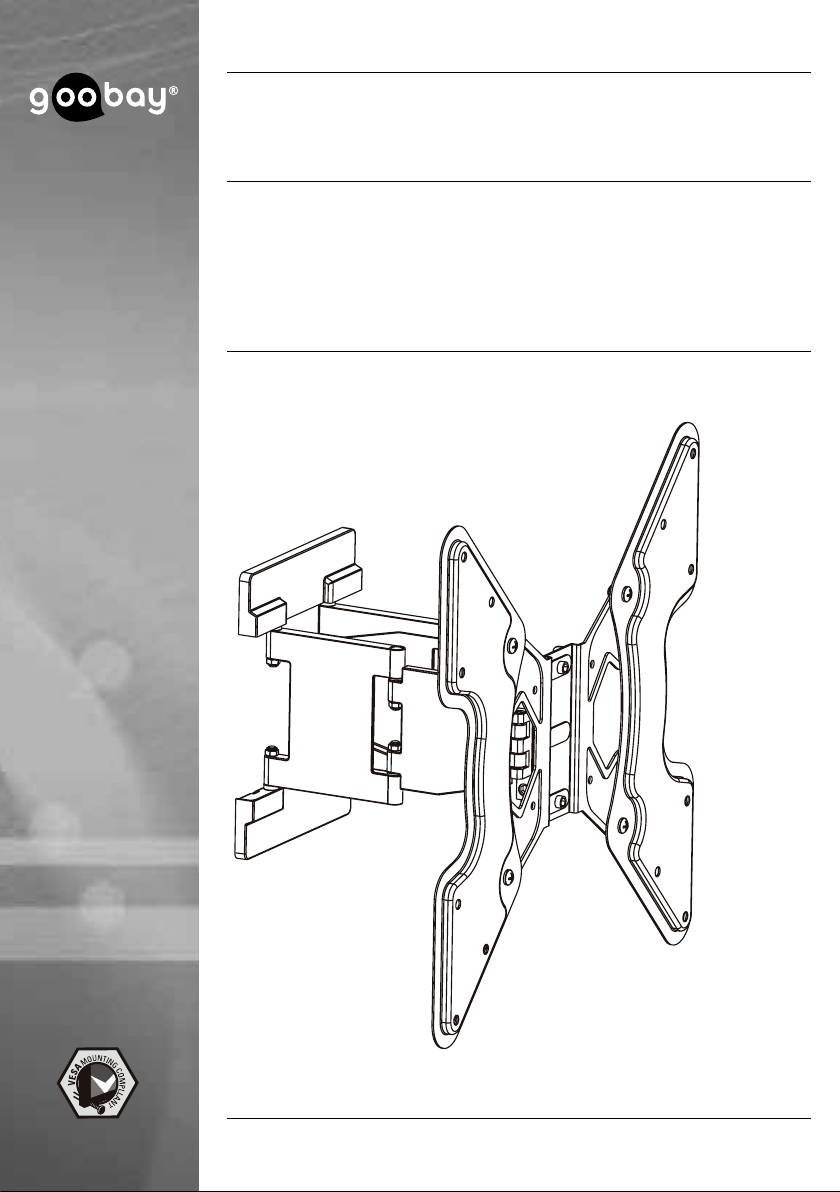
2 Beschreibung und Funktion
Ihr Wandhalter dient der Montage Ihres Flachbildschirms an stabilen, vertikalen
Wänden. Die Doppelügel-Bauart vereint Gewichtsersparnis und Stabilität.
Der TV-Wandhalter ist vertikal neigbar sowie horizontal schwenkbar und ist für
Flachbildschirme von VESA 100x100mm bis 400x400mm geeignet.
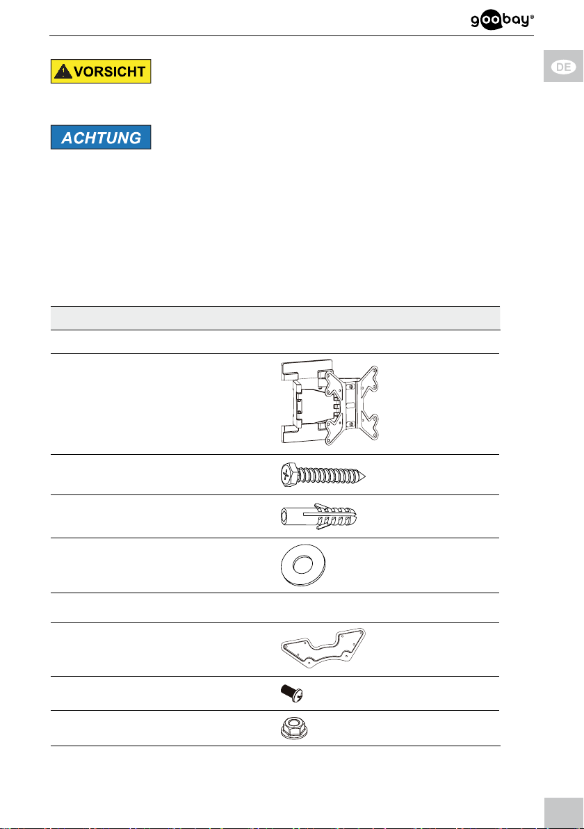
2.1 Lieferumfang
Teil Abbildung Kürzel Anzahl
Wandmontage
Wandhalter mit
VESA-Platte und
Kunststoffabdeckungen
A 1
Wandschraube 6.3x55
Betondübel
Unterlegscheibe D6
TV-Wandhaltermontage
VESA-Adapter B 2
M8x15
Mutter M8
W-A 6
W-B 6
W-C 6
C 4
D 4
5
Page 6
Betriebsanleitung
Flachbildschirmmontage
M5x14 M-A 4
M6x14
M8x20
M6x30
M8x30
Unterlegscheibe D5
Unterlegscheibe D8
TV-Abstandhalter
TV-Abstandhalter
Werkzeug
Innensechskant-Schlüssel E 1
M-B 4
M-C 4
M-D 4
M-E 4
M-F 4
M-G 4
M-H 8
M-I 4
Schraubenschlüssel
Tab. 2 : Lieferumfan g
F 1
2.2 benötigtes Werkzeug
Werkzeug Abbildung
Leitungsprüfer
Wasserwaage
6
Page 7
Stift
Kreuzschlitz-Schraubendreher
Bohrmaschine
Beton-/Steinbohrer 8x60mm
zweite Person
Tab. 3 : benötigtes Werkzeug
3 Bestimmungsgemäßer Gebrauch
Dieses Produkt dient dazu, Flachbildschirme mit spezischen Bildschirmdiagonalen, Gewichten und Befestigungspunkten, die in Kapitel „technische Daten“
zusammengefasst sind, an eine vertikale Wand zu montieren. Eine andere als in
Kapitel „Beschreibung und Funktion“ beschriebene Verwendung ist nicht
gestattet. Das Nichtbeachten und Nichteinhalten dieser Bestimmungen und der
Sicherheitshinweise kann zu schweren Unfällen, Personen- und Sachschäden
führen. Beachten Sie dazu auch das Kapitel „Gewährleistung und Haftung“.
3.1 Nutzungsbeschränkungen
Nur in trockenen Innenräumen verwenden.
4 Montage
4.1 Vorbereitung Vollständigkeit und Unversehrtheit prüfen
>> Packungsinhalt mithilfe des Lieferumfangs auf Vollständigkeit und
Unversehrtheit kontrollieren.
7
Page 8
Betriebsanleitung
Kompatibilität sicherstellen
Tab. 4 : Kompatibilität sicherstellen
4.2 Wandmontage
Tab. 5 : Wandmontage
Sachschaden durch inkompatible Produktkombinationen
>> Technische Daten aller verwendeter Produkte
vergleichen. Diese müssen übereinstimmen oder im
angegebenen Bereich liegen.
Verletzungsgefahr durch ungeeignete Umgebungsbedingungen
>>>>Wandstruktur vor Montage überprüfen bzw. sichere
Stelle zur Montage auszuwählen.
Auf in der Wand liegende, stromführende Kabel oder
andere Leitungen achten und diese nicht beschädigen!
>> Nicht an Stellen mit direkter Sonneneinstrahlung bzw.
starkem Licht montieren. Dies fördert das Ermüden
der Augen.
Sachschaden durch ungeeignete Umgebungsbedingungen
>> Um Quell- und Ausgabegeräte sowie um Schwenk-
und Neigbereich ausreichend Platz für gute Belüftung
und Beweglichkeit lassen.
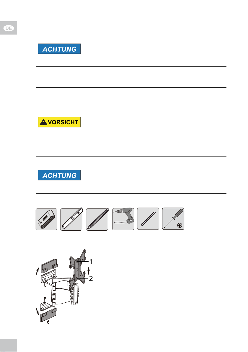
4.2.1 Vorbereitung
1. Entfernen Sie die 2 Kunststoffabde
ckungen des Wandhalters (A)
indem Sie die obere schräg nach vorn
oben und die untere nach vorn unten
schieben.
2. Entfernen Sie die VESA-Platte indem
Sie diese nach vorn und oben aus der
Führung
Achten Sie darauf, dass die Schrauben 1 und 2 fest
in der VESA-Platte stecken.
Fig. 1: Kunststoffabdeckungen und VESA-Plat te
entfernen
8
schieben.
Page 9
3. Drehen Sie die Mutter M8 (D) im
Uhrzeigersinn auf Schraube 1 locker
2-3 Umdrehungen auf.
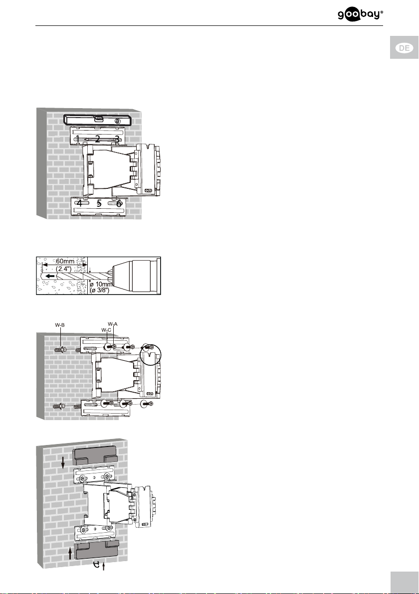
4.2.2 Ausführung
1. Prüfen Sie vor dem Bohren, ob sich
Gas-, Wasser- oder Stromleitungen in
Sie diese nicht.
2. Benutzen Sie eine Wasserwaage um
die Bohrlöcher zu markieren.
3. Markieren Sie die Bohrlöcher 1 bis 6
mit einem Stift.
Der Wandhalter (A) dient als Schablone.
Fig. 2: Ausrichten und Anzeichnen
4. Bohren Sie die Löcher mit einem
10mm-Steinbohrer 60mm tief.
Fig. 3: Löcher bohren
5. Stecken Sie jeweils einen Wanddübel
(W-B) in die Bohrlöcher.
6. Bringen Sie den Wandhalter (A) mit
den Wandschrauben (W-A) und
Unterlegscheiben (W-C) so an, dass
die Kerbe an der VESA-Plattenauf nahme nach oben zeigt.
der Wand benden und beschädigen
Fig. 4: Wandmontage
7. Stecken Sie die Kunststoffabdeckun-
gen wieder auf den Wandhalter (A).
Fig. 5: Kunststoffabdecku ngen aufstecken
9
Page 10
Betriebsanleitung
4.3 Flachbildschirmmontage
Verletzungsgefahr durch Stolpern und Sturz
>> Produkt, Produktteile und Zubehör sicher platzieren,
installieren und transportieren.
Sachschaden durch ungeeignete Vorgehensweise
>> Beim Anziehen von Schrauben mäßige Kraft aufwen-
den, um Gewinde nicht zu beschädigen.
>>>>Flachbildschirm NIE ach auf den Boden legen.
Flachbildschirm nicht durch zu lange Schrauben
beschädigen.
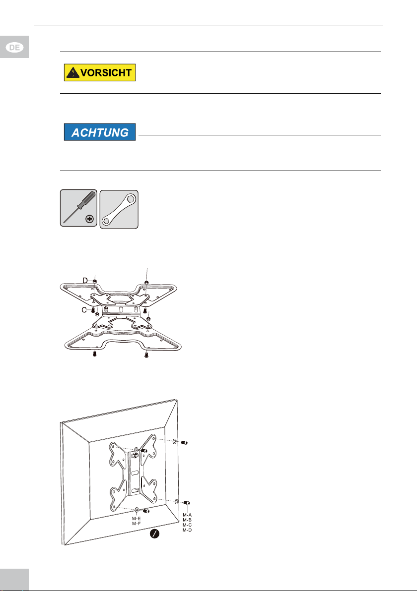
Tab. 6 : Flachbildschirmmontag e
1. Messen Sie die Befestigungslochab-
stände Ihres Flachbildschirms aus.
2. Montieren Sie Flachbildschirme der
VESA-Größen 100x100mm,
100x200mm und 200x200mm direkt
an der VESA-Platte wie in Kapitel
4.3.1 und 4.3.2 beschrieben.
3. Montieren Sie Flachbildschirme der
VESA-Größen 300x300m,
400x200mm und 400x400mm, indem
Sie die VESA-Platte zuerst mittels
Schrauben (C) und Muttern (D) mit
dem VESA-Adapter (B) verbinden.
Fig. 6: Flachbildschirmmontage
B
B
4.3.1 FlachbildschirmemitacherRückseite
1. Lehnen Sie den Flachbildschirm
vertikal gegen eine weiche, großä-
chige Unterla ge oder eine Wand und
sichern Sie ihn gegen Kratzer und
Umkippen.
2. Montieren Sie die VESA-Platte mit
den zu Ihrem Flachbildschirm
passenden Unterlegscheiben und
Schrauben an der Flachbildschirm rückseite wie abgebildet.
Fig. 7: F lachbildsch irme mit acher R ückseite
Flachbildschirmoberseite sitzt, wie in Kapitel
10
Achten Sie darauf, dass die Schraube 1 mit
der vormontierten Mutter M8 (D) an der
Page 11
4.2 berschrieben. Diese hält VESA-Platte und Flachbildschirm beim Einhängen
in den Wandhalter.
4.3.2 Flachbildschirme mit gewölbter Rückseite
1. Lehnen Sie den Flachbildschirm
vertikal gegen eine weiche, großä-
chige Unterla ge oder eine Wand und
sichern Sie ihn gegen Kratzer und
2. Montieren Sie die VESA-Platte mit
den zu Ihrem Flachbildschirm
Fig. 8: Flach bildschirm e mit gewölbter Rüc kseite
passenden Unterleg scheiben,
Schrauben und TV-Abstandhaltern
an der Flachbildschirmrückseite wie
abgebildet.
Achten Sie darauf, dass die Schraube 1 mit
der vormontierten Mutter M8 (D) an der
Flachbildschirmoberseite sitzt, wie in Kapitel
4.2 berschrieben. Diese hält VESA-Platte
und Flachbildschirm beim Einhängen in den
TV-Wandhalter.
Umkippen.
4.4 Einhängen des Flachbildschirms Verletzungsgefahr durch Stolpern und Sturz
>>>>Produkt, Produktteile und Zubehör sicher platzieren,
installieren und transportieren.
Bei Arbeiten mit Lasten sich und den Arbeitsort
sichern und von zweiter Person helfen lassen.
Sachschaden durch ungeeignete Umgebungsbedingungen
>> Um Quell- und Ausgabegeräte sowie um Schwenk-
und Neigebereich ausreichend Platz für gute Belüftung und Beweglichkeit lassen.
Tab. 7: Einhängen des Flachbildschirms
11
Page 12

Betriebsanleitung
1. Hängen Sie den mit der VESA-Platte
(und den VESA-Adaptern (B)) verbun denen Flachbildschirm zusammen
mit einer 2. Person mit der Schraube
1 und der Mutter M8 (D) schräg auf
die Kerbe des TV-Wandhalters (A).
2. Stellen Sie den Flachbildschirm
gerade.
Fig. 9: Einhängen des Flachbildschirms
3. Schrauben Sie die Muttern M8 (D) im
Uhrzeigersinn auf die Schrauben 1
und 2 bis diese fest sitzen. Benutzen
Sie hierzu den Schraubenschlüssel
(F).
Fig. 10: Anschrauben des Flachbildschirms
Ende der Montage. Zur Demontage gehen Sie in rückwärtiger
Reihenfolge vor.
5 Ausrichten des Flachbildschirms
Verletzungsgefahr durch bewegliche Produktteile
>>>>Gliedmaßen während des Gebrauchs nicht zwischen
Scherteile halten.
Während des Gebrauchs auf die Beweglichkeit des
Produktes achten. Dieses kann sich von der Wand
weg oder auf sie zu bewegen und seitlich ausschwenken.
Tab. 8 : Ausrichten des Flachbildschirms
12
Page 13
Richten Sie den Flachbildschirm nach
Bedarf
>> vertikal,
>> horizontal und/oder
>> in der Rotationsachse aus.
Gerätekabel können aufgrund der
Beweglichkeit des Wandhalters
nachträglich angeschlossen werden.
Fig . 11: Ausr ichten des Flachbildschirms
6 Gewährleistung und Haftung
• Der Hersteller gewährt auf ein neues Produkt 2 Jahre gesetzliche Gewähr-
leistung.
• Da der Hersteller keinen Einuss auf die Installation des Produktes hat,
deckt die Gewährleistung nur das Produkt selbst ab.
• Falls ein Fehler oder Defekt an Ihrem Gerät festgestellt werden sollte,
wenden Sie sich bitte an Ihren Fachhändler und zeigen Sie ggf. Ihre
Quittung oder Rechnung als Kaufnachweis vor. Ihr Händler wird den Fehler
entweder vor Ort beheben, oder das Produkt an den Hersteller weiterleiten.
Sie erleichtern den Technikern ihre Arbeit sehr, wenn Sie eventuelle Fehler
ausführlich beschreiben – nur dann haben Sie Gewähr, dass auch selten
auftretende Fehler mit Sicherheit gefunden und beseitigt werden!
• Der Hersteller haftet nicht für Personen- oder Sachschäden, die durch
unsachgemäße Installation, Betrieb oder Wartung entstanden sind.
• Ein anderer als in dieser Betriebsanleitung beschriebener Einsatz ist
unzulässig und führt zu Gewährleistungsverlust, Garantieverlust und
Haftungsaus schluss.
• Druckfehler und Änderungen an Gerät, Verpackung oder Dokumentation
behalten wir uns vor.
7 Pege,Wartung,LagerungundTransport
• Das Produkt darf nur von einer Fachwerkstatt gewartet werden.
• Schützen Sie die Gelenke vor Schmutz und schmieren Sie diese regelmäßig
mit leichtem Maschinenöl.
• Reinigen Sie es nur mit einem trockenen, weichen Tuch. Gehen Sie beim
Reinigen vorsichtig vor, um Kratzer zu vermeiden. Bei starken Verschmut zungen kann das Reinigungstuch leicht mit Wasser angefeuchtet werden.
Setzen Sie keine Reini gungsmittel oder Chemikalien ein, da dies das
Material angreifen kann.
• Achten Sie beim Bewegen der Geräteteile darauf, dass Sie keine Körperteile
13
Page 14

Betriebsanleitung
darin einklemmen!
• Kontrollieren Sie regelmäßig alle Befestigungen und Schrauben auf festen
Sitz und ziehen Sie diese bei Lockerung wieder fest. Wenden Sie aber nicht
zu viel Kraft an, um die Gewinde nicht zu überlasten.
• Vermeiden Sie Stellen mit hohen Temperaturen und Feuchtigkeit, bzw.
Stellen, die nass werden können, auch bei Wartung, Pege, Lagerung und
Transport.
• Lagern Sie Ihr Produkt bei längerem Nichtgebrauch für Kinder unzugänglich
und in trockener und staubgeschützter Umgebung.
• Befestigungsbohrungen können sichtbar bleiben, wenn das Produkt demon-
tiert wird. Nach längerem Gebrauch kann ein Fleck auf dem Untergrund
zurückbleiben.
• Heben Sie die Originalverpackung für den Transport auf, um Schäden zu
vermeiden.
8 Problembehebung
Problem Hilfe
Verkehrslasten für Wohnräume sind in diversen Europa-
Wie kann die
Wandqualität
getestet werden?
Welche Löcher
müssen gebohrt
werden?
Der Wandhalter
lässt sich schwer
ausrichten.
andere Fragen >> Händler kontaktieren.
Tab. 9 : Problembehebung
richtlinien festgelegt.
>>
Wandstärke und Material unter Putz / Tapeten
prüfen.
Fachpersonal zu Rate ziehen.
>>
>> Kapitel 4.2 lesen.
>>>>Gelenke mit Innensechskantschlüssel (E) etwas
lockern.
Die maximale Schwenkbarkeit kann bedingt durch
die TV Größe kleiner sein, als angegeben.
9 Technische Daten
Größe Angabe Einheit
TV Größe 23-55 “ / Zoll
VESA max. 400x400 mm
Trag last max. 30 kg
Neigungswinkel +/-15 °
Schwenkwinkel
des inneren
Kipphebels
14
+/-90 °
Page 15
Schwenkwinkel
des Äußeren
-50 ~ +90 °
Kipphebels
Rotationswinkel
der VESA-Platte
+/-5 °
Wandabstand 37-272 mm
Maße 450 x 450 x 37-272 mm
Gewicht 4.125 kg
Tab. 1 0 : Technische Daten
10 Informationen zum VESA-Standard
Um die Befestigungsmöglichkeiten von Monitoren, TV-Geräten und deren
Ständer und Wandhalter benutzerfreundlich zu vereinheitlichen, hat die VESA
(Video Electronic Standard Organisation) für die oben genannten Anwendungen
3 Standards festgelegt. Mit Hilfe des auf Ihrem Anzeigegerät oder in dessen
Betriebsanleitung stehenden jeweiligen VESA-Standards und den technischen
Daten in dieser Anleitung können Sie die möglichen Befestigungspunkte denieren. Einige Modelle lassen eine stufenlose, individuelle Befestigung zu.
(z.B. 300 x 300mm für Sony TVs).
VESA Klasse Befestigungslochabstand von Flachbildschirmen
MIS-D 75x75 / 100x100mm
MIS-E 200x100 / 200x200mm
MIS-F 400x200 / 400x400 / 600x200 / 600x400 / 800x400mm
Tab. 11 : Informationen zum VESA-Standard
11 Entsorgungshinweise
Dieses Produkt gehört nicht in den Hausmüll. Bitte geben Sie Ihr Gerät am
Ende seiner Lebensdauer an die dafür eingerichteten, öffentlichen Sammelstel-
len oder an die Verkaufsstelle kostenlos zurück. Einzelheiten zur Entsorgung
regelt das jeweilige Landesrecht. Wertstoffe werden dem Recyclingkreislauf
zugeführt, um daraus neue Rohstoffe zu gewinnen. Folgende Wertstoffe werden
in kommunalen Sammelstellen gesammelt:
• Altglas, Kunststoffe, Altmetalle, Bleche uvm.
Mit dieser Art der Verwertung von Altgeräten leisten Sie einen wichtigen Beitrag
zum Schutz unserer Umwelt.
15
Page 16

User‘s Manual
BETRIEBSANLEITUNG ............................................. 2
USER’S MANUAL
MODE D‘EMPLOI
ISTRUZIONI PER L‘USO
....................................................... 16
....................................................... 30
............................................ 46
USER’S MANUAL
Content
1 Safety Instructions ................................................................... 17
1.1 General Notes .............................................................. 17
1.2 User Groups .................................................................18
1.3 Warning Levels ............................................................. 18
2 Description and Function ......................................................... 19
2.1 Scope of Delivery ......................................................... 19
2.2 Required tools ..............................................................20
3 Intended Use ............................................................................ 21
3.1 Use restrictions .............................................................21
4 Installing ................................................................................... 21
4.1 Preparing ...................................................................... 21
4.2 Wall mounting ............................................................... 21
4.2.1 Preparing ..........................................................22
4.2.2 Implementing .................................................... 22
4.3 Mounting the at screen ............................................... 23
4.3.1 Flat screens with at back ................................ 24
4.3.2
4.4 Attaching the at screen ............................................... 25
5 Aligning the at screen ............................................................26
6 Warranty and Liability .............................................................. 26
7 Maintenance, Care, Storage and Transport ............................ 26
8 Troubleshooting .......................................................................27
9 Specications...........................................................................27
10 Information for VESA standard ................................................ 28
11 Disposal Instructions ...............................................................28
Flat screens with arched back .......................... 24
16
Page 17

1 Safety Instructions
1.1 General Notes
• Read the including product documentation completely and carefully before
use. It is part of the product.
• Attend to the safety instructions in product documentation, on product and
accessories, such as on the package.
• Use product, product parts and accessories only in perfect condition.
• Keep the product documentation for other potential users and for later
requests.
• For questions, defects, mechanical damage, disturbances and other not
remediable problems, consult your dealer.
Risk of life by suffocating
Children can suffocate by swallowed or inhaled parts and insulation materials.
>> Protect small parts and insulation material against unintentionally use.
Risk of injury by tripping and falling
Unfavorable placed or installed products and cable connections can injure
persons.
>> Place, transport and install product, parts and acceories in a safe way.
>> When working with burdens, secure yourself and the working place, let a
second person help you.
>> Let only a specialist do disassembly, maintenance and repair work.
Risk of injury by cutting
Children can cut themselves on packaging materials.
>> Protect packaging materials against unintentionally use.
Risk of material damage by improper product combination
Incompatible product combination does not fulll required functions, can cause
quality losses or material damage.
>> The specications of all used products must match or be within the
specied range.
Risk of injury by inappropriate ambient conditions
Extreme conditions can injure persons.
>> Attend to live cables or other lines lying behind plaster, and do not damage
them!
>> Do not install the product to places with direct sunlight or bright light.
This contributes to eye fatigue.
Risk of injury by moving product parts
Moving product parts can pinch or squeeze limbs.
>> Do not hold limbs between shear parts during use.
>> Mind the mobility of the product during use. This may move away from the
wall or towards it and swivel sideways.
Risk of self-intervention and misuse
17
Page 18
User‘s Manual
Self-interventions and misuse hide unpredictable risks and cause expiration of
warranty.
>> Do not modify or alter either the product or the accessories!
Risk of material damage by inappropriate ambient conditions
Incorrect ambient conditions can damage things.
>> Avoid extreme conditions, such as extreme heat, coldness, humidity or
direct exposure to the sun, as well as vibrations and mechanical pressure.
>> Keep enough space around product and to the whole system to ensure
proper ventilation and mobility.
The included mounting material is only suitable for mounting on massive stone
or concrete walls.
>> For other wall types use suitable mounting material.
>> Check the stability of the system periodically after installation.
1.2 User Groups
Caused to different risk levels and hazard potentials some working steps only
may be done by trained specialists.
Working step User Group
Installing,
Uninstalling,
Aligning, Care,
Storage, Transport, Disposal
Maintenance,
Repairing
Tab. 12 : User Groups
Consumers and users with basical mechanical knowledge
can do this work.
>> Protect children and people with mental and motoral
impairments from using the product!
Trained specialists only
>> special safety measures, knowledge and tools are nec-
essary!
1.3 Warning Levels
Warnings against hazards that will result directly in serious injuries or death
in case of non-observance.
Warnings against hazards that may result in serious injuries or death in case
of nonobservance.
Warnings against hazards that may result in injuries in case of non-observance.
Warnings against hazards that may result in material damage in case of
non-observance.
18
Page 19

2 Description and Function
Your wall mount is made for mounting your at screen at stable, vertical walls.
The double wing design combines weight saving and stability. The TV wall
mount is tiltable vertically and swivelable horizontally and is suitable for at
screens from VESA 100x100mm to 400x400mm.
2.1 Scope of Delivery
Part Figure Symbol Amount
Wall mounting
Wall mount with
VESA plate and
plastic covers
A 1
Wall screw 6.3x55
Concrete anchor
Washer D6
TV- wall mount assembling
VESA Adapter B 2
M8x15
Nut M8
Flat screen mounting
M5x14 M-A 4
M6x14
M8x20
W-A 6
W-B 6
W-C 6
C 4
D 4
M-B 4
M-C 4
M6x30
M-D 4
19
Page 20

User‘s Manual
M8x30 M-E 4
Washer D5
Washer D8
TV Spacer
TV Spacer
M-F 4
M-G 4
M-H 8
M-I 4
Tools
Allen key E 1
Wrench
Tab. 13 : S cope of Deliver y
F 1
2.2 Required tools
Tool Figure
Line tester
Spirit level
Pencil
Phillips screwdriver
Drilling mashine
20
Page 21

Concrete drill 8x60mm
Second person
Tab. 14 : R equired tools
3 Intended Use
This product is made for mounting at screens with specic screen sizes,
weights and mounting points, which are summarized in chapter “Technical data“,
on a vertical wall. Another use than described in chapter “Description and
Function“ is not permitted. Neglegting and ignoring these regulations and safety
instructions can cause serious accidents, personal injury and material damage.
Also refer to chapter “Warranty and Liability“.
3.1 Use restrictions
Only use in dry interior rooms.
4 Installing
4.1 Preparing
Checking the completeness and integrity
>> Check the packing content by comparing it to the scope of delivery
regarding completeness and integrity.
Ensuring compatibility
Risk of material damage by improper product
combination
>> The specications of all used products must match or
Tab. 1 5 : Ensuring compatibility
4.2 Wall mounting Risk of injury due to inappropriate ambient con-
ditions
>>>>Check the wall structure before installing or choose a
>> Do not install the product to places with direct sun-
be within the specied range.
safe installation place.
Attend to live cables or other lines lying behind plas-
ter, and do not damage them!
light or bright light. This contributes to eye fatigue.
21
Page 22

User‘s Manual
Risk of material damage by inappropriate ambient conditions
Keep enough space around product and to the whole
>>
system to ensure proper ventilation and mobility.
Tab. 1 6 : Wall mounting
4.2.1 Preparing
1. Remove the 2 plastic covers of the
TV wall mount (A) by sliding the
upper plastic cover slopingly forwards
and upwards and the lower plastic
cover forwards and downwards.
2. Remove the VESA plate by lifting it
forwards and upwards out of its
guideway.
Make sure that the screws 1 and 2 stuck
rmlyintheVESAplate.
Fig. 12 : Removing plastic c overs and VESA pla te
loosely.
3. Turn the nut M8 (D) clockwise to
screw 1 about 2-3 turns until tting
4.2.2 Implementing
1. Before drilling, attend to live cables or
other lines lying behind plaster, and
do not damage them.
2. Use a spirit level to mark the drill
holes on the wall.
3. Mark the drill holes 1 to 6 with a
pencil.
Fig. 13: Aligning and marking
concrete drill 60mm deep.
Fig. 14: Dr illing drill holes
22
Use the wall plate (A) as template.
4. Drill the drill holes with a 10mm
Page 23

5. Plug a concrete anchor (W-B) in each
drilling hole.
6. Attach the TV wall mount (A) with wall
screws (W-A) and washers (W-C),
that the notch of the VESA plate is
pointing upwards.
Fig. 15: Wall mounting
7. Reattach the plastic covers to the TV
wall mount (A).
Fig. 16: Reat taching the pla stic covers
4.3 Mountingtheatscreen
Risk of injury by tripping and falling
>> Place, transport and install product, parts and acceo-
ries in a safe way.
Risk of material damage by improper procedure
>> Only use moderate force when tightening the screws
in order to avoid damaging threads.
>>>>NEVER set the screen on the front during installation!
Do not damage the at screen by too long screws.
Tab. 17: M ounting the at sc reen
1. Measure the mounting hole spacings
of your at screen.
2. Mount at screens of VESA sizes
100x100mm, 100x200mm and
200x200mm directly to the VESA
plate, like described in chapters 4.3.1
and 4.3.2.
23
Page 24

User‘s Manual
3. Mount at screens of the VESA sizes
300x300mm, 400x200mm and
B
400x400mm by rst connecting VESA
Adapter (B) to the VESA plate by
using the screws (C) and nuts (D).
B
Fig. 17: M ounting the at s creen
4.3.1 Flatscreenswithatback
1. Lean the at screen vertically on a
soft, large surface or a wall and
protect it of scratches and overtur ning.
2. Attach the VESA plate with the
washers and screws, tting to your
at screen, to the at screens back
like shown.
Make sure that the pre-assembled nut M8
(D)sitsonscrew1andislocatedontheat
Fig. 18: Fla t screens with a t back
mounting to the wall mount.
screens top as described in chapter 4.2. This
nutholdsVESAplateandatscreenwhen
4.3.2 Flat screens with arched back
1. Lean the at screen vertically on a
soft, large surface or a wall and
protect it of scratches and overtur ning.
2. Attach the VESA plate with the
washers, screws and TV spacers,
tting to your at screen, to the at
screens back like shown.
Fig. 19: Flat screen s with arched bac k
(D)sitsonscrew1andislocatedontheat
screens top as described in chapter 4.2. This
nutholdsVESAplateandatscreenwhen
mounting to the wall mount.
24
Make sure that the pre-assembled nut M8
Page 25

4.4 Attachingtheatscreen
Risk of injury by tripping and falling
>>>>Place, transport and install product, parts and acceo-
ries in a safe way.
When working with burdens, secure yourself and the
working place, let a second person help you.
Risk of material damage by inappropriate ambient conditions
>> Keep enough space around product and to the whole
system to ensure proper ventilation and mobility.
Tab. 1 8 : At taching the at s creen
1. Attach the VESA plate (with VESA
Adapters (B)) connected at screen
together with a 2nd person with the
screw 1 and nut M8 (D) slopingly onto
the notch of the TV wall bracket (A).
2. Set the at screen vertically.
Fig. 20: Attaching th e at screen
3. Tighten the nuts M8 (D) clockwise to
the screws 1 and 2 until tting well.
Therefor use the wrench (F).
Fig. 21: Fi xing the at scre en
Endofinstalling.Toremove,proceedinreversedorder.
25
Page 26

User‘s Manual
5 Aligningtheatscreen
Risk of injury by moving product parts
>>>>Do not hold limbs between shear parts during use.
Mind the mobility of the product during use. This may
move away from the wall or towards it and swivel
sideways.
Tab. 1 9 : A ligning the at sc reen
Align the at screen as needed
>> vertically
>> horizontally and/or
>> in rotation axis
Powercordscansubsequentlybe
connectedduetothemobilityofthe
TV wall mount.
Fig. 22: Al igning the at scr een
6 Warranty and Liability
• The producer grants a 2 years warranty to a new device.
• As the manufacturer has no inuence on installation, warranty only applies
to the product itself.
• If any fault or damage is detected on your device, please contact your dealer
and provide your sales slip or invoice as evidence of the purchase, if
necessary. Your dealer will repair the fault either on site, or send the device
to the manufacturer. You make the work of our technicians considerably
easier, describing possible faults in detail – only then you can be assured
that faults, occurring only rarely, will be found and repaired with certainty!
• The manufacturer is not liable for damages to persons or property caused by
improper installation, operation or maintenance, not described in the manual.
• Do not alter or modify the product or its accessories.
• Any use other than described in this user`s manual is not permitted and
causes loss of warranty, loss of guarantee, and non-liability.
• We reserve our right for misprints and changes of the device, packing, or
user`s manual.
7 Maintenance,Care,StorageandTransport
• The product must be maintained only by professional workshops.
• Protect the angles from dirt and grease them regularly with light machine oil.
• Use a dry and soft cloth to clean your product. Be careful to avoid scratches.
26
Page 27

Use a slightly moist cloth for heavy stains. Look out for live cables! Do not
use any cleaning supplies. This can cause burns to the materials. Avoid
liquid entry to the device.
• Make sure no body parts will be pinched in the swivel device, when parts of
the device are moved!
• Periodically check, if all attachments and screws are secured, and tighten
them again when they are loosened. This may be caused e.g. by frequent
movements. Do not overtighten screws.
• Avoid places with high temperatures, humidity, or places which can become
wet, also during maintenance, care, storage, and transport.
• Keep the product away from children and store it at dry and dust-proof places!
• Drill holes are still visible after removing the product. After use for a longer
time period, a spot may remain on the surface.
• Keep the original packing for transport and to avoid damages.
8 Troubleshooting
Problem Help
Loads for home use are regulated in various European
How to test wall
quality?
Which drill holes
must be drilled?
The wall mount is
hard to align.
Other questions >> Contact your dealer.
Tab. 2 0 : Troubleshooting
standards.
>>
Check wall thickness and material under plaster / wall
paper.
>>
Ask a specialist.
>> Read chapter 4.2.
>>>>Slightly loosen the joints with the Allen wrench (E).
Due the TV size the maximum swivel angle may be
smaller than indicated.
9 Specications
Physical size Specication Unit
TV diameter 23-55 “ / Inch
VESA max. 400x400 mm
Load max. 30 kg
Tilting angle +/-15 °
Swivel angle of
inner rocker
Swivel angle of
outer rocker
+/-90 °
-50 ~ +90 °
27
Page 28

User‘s Manual
Rotation angle of
VESA plate
+/-5 °
Wall distance 37-272 mm
Dimensions 450 x 450 x 37-272 mm
Weight 4.125 kg
Tab. 2 1: Specic ations
10 Information for VESA standard
To harmonize attachment options of monitors, TV devices and their stands and
wall brackets in a user-friendly manner, VESA (Video Electronic Standard
Organization) dened 3 standards for the applications mentioned above. Using
the relevant VESA standard specied on your display unit, or in its user‘s
manual, and the specications in Chapter Specications in this manual you are
able to dene the possible points of attachment. Some models allow for an
innitely variable individual attachment (e.g. 300 x 300 mm for Sony TVs).
VESA Class Hole distance for attachment of monitors
MIS-D 75x75 / 100x100mm
MIS-E 200x100 / 200x200mm
MIS-F 400x200 / 400x400 / 600x200 / 600x400 / 800x400mm
Tab. 2 2 : Information for VESA standard
11 Disposal Instructions
This product should not be disposed together with domestic waste. Please
return your product free of charge at the end of its service life at the producer,
the sales outlet, or a public collection point, established for this purpose. Details
for disposal are regulated in the relevant federal state law. Potential recyclable
materials are fed into the recycling cycle to obtain new raw materials from them.
Following materials are collected a local collection points:
• Waste glass, plastic, waste metal, metal sheet, and more.
This type of recycling of waste contributes signicantly to the protection of our
environment.
28
Page 29

29
Page 30

Mode d‘emploi
BETRIEBSANLEITUNG
USER’S MANUAL
MODE D‘EMPLOI
ISTRUZIONI PER L‘USO
MODE D‘EMPLOI
Contenu
1 Consignes de sécurité ....................................................................... 31
1.1 Notes général ......................................................................... 31
1.2 Groupes de l‘utilisateur .....................................................32
1.3 Niveaux de mises en garde ....................................................33
2 Description et fonction ....................................................................... 33
2.1 Contenu de la livraison ...........................................................33
2.2 Outils requis ........................................................................... 35
3 Utilisation prévue ............................................................................... 35
3.1 Restrictions d‘utilisation .........................................................35
4 Installation ....................................................................................36
4.1 Préparation ........................................................................ 36
4.2 Montage mural .......................................................................36
4.2.1 Préparation .................................................................37
4.2.2 Exécution ...................................................................37
4.3 Montage de l‘écran plat ..........................................................38
4.3.1 Ecrans plats avec face arrière plane ......................... 39
4.3.2 Ecrans plats avec face arrière courbée ..................... 39
4.4 Montage de l‘écran plat .......................................................... 39
5 Ajuster l‘ecran plat ............................................................................. 41
6 Garantie et responsabilité .............................................................41
7 Entretien, maintenance, stockage et transport ................................. 42
8 Dépannage ....................................................................................42
9 Spécications .................................................................................... 43
10 Informations sur la norme VESA ....................................................... 43
11 Instructions pour l’élimination ............................................................44
............................................. 2
....................................................... 16
....................................................... 30
............................................ 46
30
Page 31

1 Consignes de sécurité
1.1 Notes général
• Lisez attentivement toute la documentation du produit fournie avant utilisati on. Elle fait partie du produit.
• Consultez les consignes de sécurité de la documentation du produit, sur le
produit et les accessoires, comme l‘emballage.
• N‘utilisez le produit, les pièces du produit et les accessoires que s‘ils sont en
parfait état.
• Conservez la documentation du produit pour d‘autres utilisateurs potentiels
et pour une utilisation ultérieure.
• Pour des questions, des défauts, des dommages mécaniques, des perturba tions et d‘autres problèmes qui ne semblent pas avoir de solution, consultez
votre revendeur.
Risque de mort par suffocation
Il existe un risque de mort par suffocation pour les enfants s‘ils avalent ou
inhalent les pièces et les matériaux d‘isolation.
>> Protégez les petites pièces et le matériau d‘isolation contre une utilisation
involontaire.
Risque de blessures par trébuchement ou par chute
Les produits et les câbles de connexion placés ou installés dans des endroits
inappropriés peuvent entraîner des blessures.
>> Placez, transportez et installez le produit, les pièces et les accessoires
en toute sécurité.
>> Quand vous travaillez avec des charges, travaillez en sécurité et travail
lez dans un environnement de travail en toute sécurité, et faites-vous
aider par une seconde personne.
>> Laissez uniquement un spécialiste effectuer les opérations de démonta-
ge, d‘entretien et de réparation.
Risque de blessures par coupures
Les enfants peuvent se couper avec les matériaux d‘emballage.
>> Protégez les matériaux d‘emballage contre une utilisation involontaire.
Risque de blessures par conditions ambiantes inappropriées
Des conditions extrêmes peuvent entraîner des blessures.
>> Faites attention aux câbles sous tension ou aux autres lignes posées
derrière le plâtre, et ne les endommagez pas!
>> N‘installez pas le produit dans un endroit en contact direct avec la
lumière du soleil ou à la lumière vive. Ceci contribue à la fatigue oculaire.
Risque de blessure par des pièces mobiles du produit
Les pièces mobiles peuvent pincer ou serrer les membres du produit.
>> Pas tenir les membres lors de l‘utilisation entre les parties de cisaille-
ment.
31
Page 32

Mode d‘emploi
>> En cours d‘utilisation, an d‘assurer la souplesse du produit.
C‘est peut-être de s‘éloigner du mur ou sur eux et déplacement latéral.
Risque d‘intervention personnelle et de mauvaise utilisation
Les interventions personnelles et les mauvaises utilisations cachent des risques
difciles à prévoir et peuvent entraîner une n de garantie.
>> Ne modiez ni le produit ni les accessoires!
Risque de dommage du matériau par combinaison inappropriée du
produit
La combinaison du produit incompatible ne répond pas aux fonctions requises,
elle peut entraîner une perte de qualité ou un dommage matériel.
>> Les spécications de tous les produits utilisés doivent correspondre ou
être comprises dans la gamme spéciée.
Risque de dommage matériel par conditions ambiantes inappropriées
Des conditions ambiantes inappropriées peuvent endommager les objets.
>> Evitez les conditions extrêmes, comme la chaleur extrême, le froid,
l‘humidité ou l‘exposition directe au soleil, ainsi que les vibrations et la
pression mécanique.
>> Conservez un espace sufsant autour du produit et vers tout le système
pour assurer une ventilation correcte et permettre la mobilité.
Le matériel de montage fourni convient uniquement au montage sur de grosses
pierres ou sur des murs en béton.
>> Pour les autres types de murs, utilisez un matériel de montage approprié.
>> Vérier la stabilité du système périodiquement après l‘installation.
1.2 Groupes de l‘utilisateur
A cause de risques de niveaux différents et de dangers potentiels, certains
travaux ne peuvent être effectués que par des spécialistes entraînés.
Etape de travail Groupe de l‘utilisateur
Installation, désinstallation, alignement,
entretien, stockage,
transport, élimination
Entretien, réparation
Tab. 2 3 : G roupe de l‘utilisateur
32
Les consommateurs et les utilisateurs ayant une
connaissance mécanique de base peuvent effectuer
ce travail.
>> Ne laissez pas les enfants et les personnes souf
frant de déciences mentales et motrices utiliser le
produit!
Uniquement réservé aux spécialistes entraînés
>> Des mesures de sécurité particulières, une con-
naissance et des outils spéciaux sont nécessaires!
Page 33

1.3 Niveaux de mises en garde
Mises en garde contre les dangers entraînant directement des blessures
sérieuses ou la mort en cas de non respect.
Mises en garde contre les dangers pouvant entraîner des blessures graves ou
la mort en cas de non respect.
Mises en garde contre les dangers pouvant entraîner des blessures en cas de
non respect.
Mises en garde contre les dangers pouvant entraîner un dommage matériel en
cas de non respect.
2 Description et fonction
Votre montage mural est conçu pour installer votre écran plat sur des murs
verticaux stables. La conception à double aile combine des économies de poids
et de stabilité. Le TV support mural est inclinable paroi verticale et de rotation
horizontal et il est adapté pour les téléviseurs plats de VESA 100x100mm à
400x400mm.
2.1 Contenu de la livraison
Partie Figure
Montage mural
Support mural avec
Plate VESA et
Couvercles
Vis murale de 6.3x55
Vis d‘ancrage à béton
Rondelle D6
Rac-
courci
A 1
W-A 6
W-B 6
W-C 6
Nom-
bre
33
Page 34

Mode d‘emploi
Montage du TV support mural
Aadaptateur VESA B 2
M8x15
Écrou M8
Écran plat de montage
M5x14 M-A 4
M6x14
M8x20
M6x30
M8x30
Rondelle D5
Rondelle D8
C 4
D 4
M-B 4
M-C 4
M-D 4
M-E 4
M-F 4
M-G 4
Rondelle d‘espacement TV
Rondelle d‘espacement TV
M-H 8
M-I 4
Outils
Clé Allen E 1
Clé
Tab. 2 4 : Contenu de la livraison
34
F 1
Page 35

2.2 Outils requis
Outil Figure
Testeur de ligne
Niveau à bulle
Crayon
Tournevis cruciforme
Perceuse électrique
Mèche à béton de 8 x 60 mm
Seconde personne
Tab. 2 5 : O utils requis
3 Utilisation prévue
Ce produit est destiné au montage des écrans plats de tailles d‘écrans, de poids
et de points de montage spéciques sur un mur vertical, résumés dans le
chapitre „Données techniques“. Une autre utilisation décrite dans le chapitre
„Description et fonction“ n‘est pas autorisée. La négligence et l‘ignorance de
ces règles et consignes de sécurité peuvent causer de graves accidents, des
blessures et des dommages matériels. Reportez-vous aussi au chapitre
„Garantie et responsabilité“.
3.1 Restrictions d‘utilisation
Utiliser uniquement dans des locaux secs.
35
Page 36

Mode d‘emploi
4 Installation
4.1 Préparation
Vériezl‘intégralitéetl‘intégrité
>> Vériez le contenu de l‘emballage en le comparant à la livraison concer-
nant l‘intégralité et l‘intégrité.
Assurer la compatibilité
Risque de dommage du matériau par combinaison inappropriée du produit
>> Les spécications de tous les produits utilisés doivent
correspondre ou être comprises dans la gamme
spéciée.
Tab. 2 6 : A ssurer la compatibilité
4.2 Montage mural Risque de blessures par conditions ambiantes
inappropriées
>>>>Vériez la structure murale avant l‘installation ou
choisissez un emplacement d‘installation sans
risque.
Faites attention aux câbles sous tension ou aux
autres lignes posées derrière le plâtre, et ne les
endommagez pas!
>> N‘installez pas le produit dans un endroit en contact
direct avec la lumière du soleil ou à la lumière vive.
Ceci contribue à la fatigue oculaire.
Risque de dommage matériel par conditions
ambiantes inappropriées
>> Conservez un espace sufsant autour du produit
et vers tout le système pour assurer une ventilation
correcte et permettre la mobilité.
Tab. 2 7 : M ontage mural
36
Page 37

4.2.1 Préparation
1. Supprimer en poussant le haut
obliquement vers l‘avant et au-des sus de la partie inférieure de l‘avant
sur les deux couvercles en plastique
sur le support mural (A).
2. Retirer la plate VESA en le faisant
glisser vers l‘avant et vers le haut du
guide.
Assurez-vous que les vis 1 et 2 coincés dans
la plate VESA.
Fig. 23: Su pprimer les co uvercles en plas tique et la
plate VESA
pour visser 2-3 tours un lâche.
4.2.2 Exécution
1. Faites attention aux câbles sous
tension ou aux autres lignes posées
derrière le plâtre, et ne les endomma-
gez pas.
2. Utilisez un niveau à bulles pour
marquer les trous de perçage sur le
mur.
3. Marquez les trous de 1 à 6 avec un
stylo.
Fig. 24: Al ignement et marq uage
3. Tourner l‘écrou M8 (D) vers la droite
Le support mural (A) sert de matrice.
4. Percez les trous de 60 mm de
profondeur avec une mèche à béton
de 10 mm.
Fig. 25: Perc er les trous
5. Bouchez avec une vis d‘ancrage à
béton (W-B) dans chaque trou de per çage.
6. Fixez le support mural (A) avec les vis
murales (W-A) et les rondelles (W-C)
de sorte que l‘encoche de la plate
VESA indique tir vers le haut.
Fig. 26: Montage mural
37
Page 38

Mode d‘emploi
7. Monter les couvercles en plastique
sur le TV support mural (A).
Fig. 27: Monter les cou vercles en plast ique
4.3 Montage de l‘écran plat Risque de blessures par trébuchement ou par
chute
>> Placez, transportez et installez le produit, les pièces
et les accessoires en toute sécurité.
Risque de dommage matériel causé par une procédure inappropriée
>> Serrez les vis modérément pour éviter
d‘endommager le letage.
>>>>Ne positionnez JAMAIS l‘écran devant durant
l‘installation!
N‘endommagez pas l‘écran plat en utilisant des vis
trop longues.
Tab. 2 8 : M ontage de l‘écr an plat
1. Mesure de l‘espacement des trous
de montage de votre écran plat.
2. Assemblez les écrans plats de VESA
tailles 100x100mm, 100x200mm et
200x200mm décrit directement sur la
plate VESA comme décrit dans les
sections 4.3.1 et 4.3.2.
3. Monter par connecter des écrans
plats de VESA tailles 300x300m,
400x200mm et 400x400mm par plate
VESA abord avec les vis (C) et les
écrous (D) avec l‘adaptateur VESA
(B).
Fig. 28: Mon tage de l‘écran pl at
B
B
38
Page 39

4.3.1 Ecrans plats avec face arrière plane
1. Posez l‘écran plat verticalement sur
une surface souple, large ou sur un
mur et proté gez-le contre les rayures
et le renversement.
2. Monter la plate VESA avec les
rondelles et les vis, ajuster à votre
écran plat, des écrans plats en arrière
comme montré.
Assurez-vous que l‘écrou M8 (D) prémonté
se trouve sur la vis 1 et est situé sur les
écrans plats principaux tels que décrits dans
Fig. 29: Ecrans pla ts avec face arri ère plane
le chapitre 4.2. Cet écrou détient plate VESA
et l‘écran plat lors du montage de la support
murale.
4.3.2 Ecrans plats avec face arrière courbée
1. Posez l‘écran plat verticalement sur
une surface souple, large ou sur un
mur et protégez-le contre les rayures
et le renversement.
2. Monter la plate VESA avec les
rondelles, les vis et les rondelles
d‘espacement TV, ajuster à votre
écran plat, des écrans plats en arrière
comme montré.
Fig. 30: Ecr ans plats avec fac e arrière cour bée
Assurez-vous que l‘écrou M8 (D) prémonté
se trouve sur la vis 1 et est situé sur les
écrans plats principaux tels que décrits dans
le chapitre 4.2. Cet écrou détient plate VESA
et l‘écran plat lors du montage de la support
murale.
4.4 Montage de l‘écran plat Risque de blessures par trébuchement ou par
chute
>>>>Placez, transportez et installez le produit, les pièces
et les accessoires en toute sécurité.
Laissez uniquement un spécialiste effectuer les opé-
rations de démontage, d‘entretien et de réparation.
39
Page 40

Mode d‘emploi
Risque de dommage matériel par conditions
ambiantes inappropriées
>> Conservez un espace sufsant autour du produit
et vers tout le système pour assurer une ventilation
correcte et permettre la mobilité.
Tab. 2 9 : Monta ge de l‘écran plat
1. Accrocher l‘reliée l‘écran et le plate
VESA conjointement avec un second
personne avec la vis 1 et l‘écrou M8
(D) de inclinées dans la cran du TV
support mural (A).
2. Régler l‘ecran plat vertical.
Fig. 31: Mo ntage de l‘écran p lat
3. Visser les écrous M8 (D) dans le sens
horaire sur les vis 1 et 2 jusqu‘à ce
qu‘ils s‘intègrent. Pour cela, utilisez la
clé (F).
Fig. 32: Vis sez l’écran plat
Fin de l‘assemblage. Procéder dans l‘ordre inverse du démontage.
40
Page 41

5 Ajuster l‘ecran plat
Risque de blessure par des pièces mobiles du
produit
>>>>Pas tenir les membres lors de l‘utilisation entre les
parties de cisaillement.
En cours d‘utilisation, an d‘assurer la souplesse du
produit. C‘est peut-être de s‘éloigner du mur ou sur
eux et déplacement latéral.
Aligner l‘écran plat au besoin
>> verticalement
>> horizontalement et / ou
>> dans l‘axe de rotation
Les cordons d‘alimentation peuvent
être connectés par la suite en raison
delamobilitédelaxationmurale.
Fig. 33: Aju ster l‘ecran pla t
6 Garantie et responsabilité
• Le fabricant accorde une garantie de 2 ans à un appareil neuf.
• Comme le fabricant n‘a aucune inuence sur l‘installation, la garantie
s‘applique uniquement au produit lui-même.
• Si vous détectez un défaut ou un dommage sur votre appareil, veuillez
prendre contact avec votre détaillant et, si nécessaire, fournir le ticket de
vente ou la facture comme preuve d‘achat. Votre revendeur réparera
l‘appareil sur place, ou bien renverra l‘appareil au fabricant. Vous rendez le
travail de nos techniciens considérablement plus facile en décrivant les
défauts possibles en détail - alors seulement vous pourrez être assuré que
les défauts qui ne se produisent que rarement, pourront être détectés et
réparés à coup sûr!
• Le fabricant n‘est pas responsable des dommages physiques ou matériels
causés par une mauvaise installation ou maintenance, ou une opération non
décrite dans le présent manuel.
• Ne modiez pas et n‘altérez pas le produit ni ses accessoires.
• Toute utilisation autre que celle décrite dans le présent manuel d’utilisation
est interdite, et provoque l‘annulation de la garantie et nous dégage de toute
responsabilité.
• Nous réservons tous les droits en cas d’erreur d‘impression et de modica tion de l‘appareil, de l‘emballage ou du manuel d‘utilisation.
41
Page 42

Mode d‘emploi
7 Entretien,maintenance,stockageettransport
• Le produit ne doit être maintenu que par des ateliers professionnels.
• Protégez les angles contre la saleté et graissez-les régulièrement avec de
l‘huile légère pour machine.
• Utilisez un linge sec pour nettoyer votre produit. Faites attention à éviter les
éraures. Utilisez un chiffon légèrement humide pour les taches tenaces.
Attention aux câbles sous tension ! N‘utilisez aucun produit de nettoyage.
Cela peut entraîner des brûlures aux matériaux. Évitez l‘entrée de liquides
dans l‘appareil.
• Assurez-vous qu‘aucune partie du corps ne reste coincée dans le dispositif
de pivotement, lorsque des parties du dispositif sont déplacées !
• Vériez régulièrement que toutes les xations et vis sont bien solidement
ancrées, resserrez-les lorsqu‘elles sont desserrées. Ceci peut être provoqué
par exemple par les mouvements fréquents. Ne serrez pas trop les vis.
• Évitez les endroits à fortes températures ou forte humidité, les endroits où
l‘appareil risque d‘être mouillé, que ce soit en cours d‘entretien, de mainte nance, de stockage ou de transport.
• Gardez le produit loin des enfants et stockez-le dans des endroits secs et
hors poussière !
• Les trous de perçage restent visibles après avoir enlevé le produit. Après
une période de temps prolongée, une marque peut apparaître sur la surface.
• Conservez l‘emballage d‘origine pour le transport et pour éviter des dom-
mages.
8 Dépannage
Problème Aide
Les charges domestiques sont réglementées dans les
Comment tester
la qualité murale?
Quels trous doi-
vent être percés?
Il est difcile
d‘aligner le mon-
tage mural.
Autres questions >> Contactez votre revendeur.
Tab. 3 0: Dépannage
42
diverses normes européennes.
>> Vériez l‘épaisseur murale et celle du matériau sous le
plâtre / papier peint.
>> Demandez à un spécialiste.
>> Lisez le chapitre 4.2.
>> Dévisser la joints avec une clé Allen (E) desserrer.
>> Le maximum angle de pivotement peut en raison
la taille de la TV peut être inférieure à celle indiquée.
Page 43

9 Spécications
Taille Spécication Unité
TV Taille 23-55 “ / Pouce
VESA max. 400x400 mm
Charger max. 30 kg
Angle
d'inclinaison
+/-15 °
Angle de
pivotement
culbuteur
+/-90 °
intérieur
Angle de
pivotement
culbuteur
-50 ~ +90 °
extérieur
Angle de
rotation
+/-5 °
Distance du mur 37-272 mm
Dimensions 450 x 450 x 37-272 mm
Poids 4.125 kg
Tab. 3 1: Spécications
10 Informations sur la norme VESA
Pour harmoniser de façon conviviale les options de branchement des moni-
teurs, des appareils de télévision et de leurs stands et supports, la VESA (Video
Electronic Standard Organization : Organisation de normalization de
l‘électronique vidéo) a dene trois normes pour les applications mentionnées
ci-dessus. À l‘aide de la norme VESA applicable spéciée sur votre écran, ou
dans son guide de l‘utilisateur, et des caractéristiques précisées dans le
Chapitre Caractéristiques du present guide, vous êtes en mesure de dénir les
points de xation possibles. Certains modèles permettent des xations individuelles variables à l‘inni. (par exemple 300 x 300 mm pour Sony TVs)
Classe VESA Distancedestrouspourlaxationdesmoniteurs
MIS-D 75 x 75 / 100 x 100 mm
MIS-E 200 x 100 / 200 x 100 mm
MIS-F 400x200 / 400x400 / 600x200 / 600x400 / 800x400mm
Tab. 3 2 : Informations sur la norme VESA
43
Page 44

Mode d‘emploi
11 Instructions pour l’élimination
Ce produit ne doit pas être mis au rebut avec les déchets ménagers. Veuillez
déposez gratuitement votre appareil en n de vie à un point de récupération des
déchets destiné à cet effet, ou auprès de votre point de vente. Les détails
concernant la mise au rebut sont règlementés par les lois d‘État et fédérales
concernées. Les éléments recyclables sont intégrés dans le cycle de recyclage
des déchets an d’en retirer de nouvelles matières premières. Les matériaux
recyclables suivants sont recueillis dans les points de recueils locaux:
• Déchets de verre, plastique, déchets métalliques, plaques métalliques, etc.
Ce type de recyclage des équipements usagés contribue de façon signicative
à la protection de notre environnement.
44
Page 45

45
Page 46

Istruzioni per l‘uso
BETRIEBSANLEITUNG
USER’S MANUAL
MODE D‘EMPLOI
ISTRUZIONI PER L‘USO
ISTRUZIONI PER L‘USO
Contenuto
1 Istruzioni per la sicurezza .................................................................. 47
1.1 Note Generali ......................................................................... 47
1.2 Gruppi utente .........................................................................48
1.3 Livelli d’avviso ........................................................................48
2 Descrizione e Funzione ..................................................................... 49
2.1 Scopo della consegna ............................................................ 49
2.2 Strumenti necessari ...............................................................50
3 Scopo d‘utilizzo .................................................................................51
3.1 Limitazioni d‘uso .....................................................................51
4 Installazione .................................................................................... 51
4.1 Preparazione ..........................................................................51
4.2 Installazione su parete ...........................................................52
4.2.1 Preparazione...............................................................52
4.2.2 Esecuzione ................................................................53
4.3 Installazione dello schermo piatto .........................................54
4.3.1 Schermi piatti con fondo piatto .................................. 54
4.3.2 Schermi piatti con fondo curvo .................................. 55
4.4 Fissare dello schermo piatto .................................................. 55
5 Allineamento dello schermo piatto .................................................... 56
6 Garanzia e responsabilità..................................................................57
7 Manutenzione, Cura, conservazione e trasporto .............................. 57
8 Risoluzione dei problemi ................................................................... 58
9 Speciche ....................................................................................58
10 Informazioni sullo standard VESA .....................................................59
11 Istruzioni sullo smaltimento ............................................................... 59
............................................. 2
....................................................... 16
....................................................... 30
............................................ 46
46
Page 47

1 Istruzioni per la sicurezza
1.1 Note Generali
• Leggere in modo completo ed accurato la documentazione del prodotto
prima dell‘uso Fa parte del prodotto.
• Osservare le istruzioni di sicurezza riportate nella documentazione del
prodotto, sul prodotto e sugli accessori, come ad esempio sulla confezione.
• Utilizzare il prodotto, le parti del prodotto e gli accessori solo se sono in
perfette condizioni.
• Conservare la documentazione del prodotto per altri potenziali utenti e per le
richieste successive.
• Consultare il rivenditore per domande, difetti, danni meccanici, disturbi ed
altri problemi non rimediabili.
Pericolo di morte per soffocamento
I bambini possono soffocare se ingoiano o inalano parti di piccole dimensioni e
materiali isolanti.
>> Proteggere le parti di piccole dimensioni ed i materiali isolanti per
prevenire usi inappropriati.
Pericolo di lesioni da incespicamento e caduta
I prodotti ed I cavi di collegamento collocati o installati in modo inappropriato
possono provocare lesioni alle persone.
>> Collocare, trasportare ed installare il prodotto, sue parti ed accessori in
modo sicuro.
>> Quando si lavora con pesi, proteggere sé stessi ed il luogo di lavoro, e
farsi aiutare da una seconda persona.
>> Permettere solo a personale specializzato di smontare, eseguire ma-
nutenzioni e riparazioni.
Pericolo di lesioni da taglio
I bambini possono tagliarsi con I materiali di imballaggio.
>> Proteggere materiali di imballaggio per prevenire usi inappropriati.
Pericolo di lesioni provocate da condizioni ambientali inappropriate
Le condizioni estreme possono provocare lesioni alle persone.
>> Prestare attenzione ai cavi elettrici ed altri li che si trovano dietro
l’intonaco, e non danneggiarli!
>> Non installare il prodotto in luoghi esposti alla luce diretta del sole o
articiale. Questo contribuisce all’affaticamento della vista.
Pericolo di lesioni da parti mobili del prodotto
Le parti mobili possono schiacciare o spremere arti del prodotto.
>> Non tenere membra durante l’uso tra le parti di taglio.
>> Durante l’uso rispetto alla mobilità del prodotto.
Questo può essere di allontanarsi dalla parete o sopra movimento
laterale.
47
Page 48

Istruzioni per l‘uso
Pericoli dovuti ad interventi autonomi ed uso improprio
Gli interventi autonomi e l’uso improprio nascondono rischi imprevedibili e
causano l’annullamento della garanzia.
>> Non modicare o alterare né il prodotto né gli accessori!
Rischio di danni materiali causati da combinazioni inappropriate di
prodotti
La combinazione di prodotti incompatibili non soddisfa le funzioni necessarie,
può causare la perdita di qualità o danni materiali.
>> Le speciche di tutti i prodotti utilizzati devono corrispondere o essere
comprese nell‘intervallo specicato.
Pericolo di danni materiali provocati da condizioni ambientali
inappropriate
Le condizioni ambientali non corrette possono danneggiare le cose.
>> Evitare condizioni estreme, come caldo, freddo, umidità o l‘esposizione
diretta al sole, così come le vibrazioni e la pressione meccanica.
>> Lasciare spazio sufciente intorno al prodotto ed all‘intero sistema per
garantire un‘adeguata ventilazione e la mobilità.
Il materiale d’installazione fornito in dotazione è adatto solo per l’installazione su
pietra massiccia o pareti di cemento.
>> Per altri tipi di pareti usare kit d’installazione appropriati.
>> Vericare la stabilità del sistema periodicamente dopo l’installazione.
1.2 Gruppi utente
A causa di diversi livelli di rischio e delle potenzialità di pericolo, alcune fasi di
lavorazione possono essere eseguite solo da personale specializzato.
Fasi di lavoro Gruppo di utenti
Installazione, rimozione, allineare, cura,
immagazzinamento,
trasporto, smalti-
mento
Manutenzione, riparazione
Tab. 3 3 : Gruppi utente
I consumatori e gli utenti con conoscenze meccaniche
di base possono eseguire questo lavoro.
>> Impedire ai bambini ed alle persone con disabilità
mentali e motorie di utilizzare il prodotto!
Solo personale specializzato
>> Sono necessari speciali misure di sicurezza, cono
scenze e strumenti!
1.3 Livelli d’avviso
Avvisi relativi ai pericoli che si traducono direttamente in lesioni gravi o morte
in caso di inosservanza.
48
Page 49

Avvisi relativi a pericoli che possono tradursi in lesioni gravi o morte in caso di
inosservanza.
Avvisi relativi a pericoli che possono tradursi in lesioni in caso di inosservanza.
Avvisi relativi a pericoli che possono tradursi in danni materiali in caso di
inosservanza.
2 Descrizione e Funzione
Il kit per installazione a parete serve per installare lo su pareti stabili e verticali.
Il design a doppia ala unisce leggerezza e stabilità. gli montaggio a parete inc-
linazione verticale e orizzontale girevole e‚ adatto per TV a schermo piatto da
VESA 100x100mm no a 400x400mm.
2.1 Scopo della consegna
Parte Figura
Installazione su parete
Supporto a parete
con coperchio di plastica
e piastra VESA
Scor-
ciatoia
Numero
A 1
Viti per parete 6.3x55
Tassello per cemento
Rondella D6
Montaggio di supporto per TV
Adattatore VESA B 2
M8x15
W-A 6
W-B 6
W-C 6
C 4
49
Page 50

Istruzioni per l‘uso
Dado M8 D 4
Montaggio a pannello piatto
M5x14 M-A 4
M6x14
M8x20 M-C 4
M6x30
M8x30
Rondella D5
Rondella D8
Distanziatore TV
Distanziatore TV
Strumenti
Chiave a brugola E 1
M-B 4
M-D 4
M-E 4
M-F 4
M-G 4
M-H 8
M-I 4
Chiave
Tab. 3 4: Scopo della consegna
F 1
2.2 Strumenti necessari
Strumento Figura
Tester di linea
50
Page 51

Livella a bolla
Matita
Cacciavite a stella
Trapano
Trapano per cemento 8 x 60mm
Seconda persona
Tab. 3 5 : St rumenti necessari
3 Scopo d‘utilizzo
Questo prodotto è realizzato per l’installazione su una parete verticale di
schermi piatti con dimensioni, pesi e punti d’installazione specici, che sono riassunti nel capitolo „Dati tecnici“. Non è consentito l’uso diverso da quello
descritto nel Capitolo „Descrizione e Funzioni“. La mancata osservanza e
trascurando le norme e le istruzioni di sicurezza si possono provocare gravi
incidenti, lesioni alle persone e danni materiali. Fare riferimento anche al
capitolo „Garanzia e responsabilità“.
3.1 Limitazioni d‘uso
Utilizzare solo in ambienti asciutti.
4 Installazione
4.1 Preparazione Controllo della completezza e dell‘integrità
>> Controllare il contenuto della confezione e confrontarlo con i Contenuti
della confezione per quanto riguarda la completezza e l‘integrità.
51
Page 52

Istruzioni per l‘uso
Garantire la compatibilità
Rischio di danni materiali causati da combinazioni inappropriate di prodotti
>> Le speciche di tutti i prodotti utilizzati devono corri-
Tab. 3 6: Garantire la compatibilità
4.2 Installazione su parete Rischio di lesioni provocate da condizioni ambi-
entali inappropriate
>>>>Controllare la struttura della parete prima di installare
>> Non installare il prodotto in luoghi esposti alla luce
Pericolo di danni materiali provocati da condizioni ambientali inappropriate
>> Lasciare spazio sufciente intorno al prodotto ed
Tab. 3 7: Inst allazione su parete
spondere o essere comprese nell‘intervallo specicato.
o scegliere un luogo sicuro per l’installazione.
Prestare attenzione ai cavi elettrici ed altri li che si
trovano dietro l’intonaco, e non danneggiarli!
diretta del sole o articiale. Questo contribuisce all’af-
faticamento della vista.
all‘intero sistema per garantire un‘adeguata ventilazione e la mobilità.
4.2.1 Preparazione
1. Rimuovere i due coperchi in plastica
del supporto a parete (A) facendo
scorrere il superiore coperchio in
plastica in avanti e verso l‘alto e il
inferiore coperchio in plastica in
avanti e verso il sotto.
2. Rimuovere la piastra VESA sollevan
dolo in avanti e verso l‘alto dalla sua
guida.
Assicurarsi che le viti 1 e 2 bloccati nella
piastra VESA.
Fig. 34: Rimozione di cop erture in plas tica e piastra
VESA
52
Page 53

3. Girare il dado M8 (D) in senso orario
per avvitare 1 circa 2-3 giri no a
quando il montaggio senza bloccare.
4.2.2 Esecuzione
1. Prima di perforare la parete, prestare
attenzione ai cavi elettrici ed altri li
che si trovano dietro l’intonaco, e non
danneggiarli!
2. Utilizzare una livella a bolla per
segnare i fori sulla parete.
3. Segnare i fori 1-6 con una matita.
Utilizzare la piastra a parete (A) come stampo.
Fig. 35: Allineamento e marcatura
4. Praticare i fori profondi 60mm con un
trapano da cemento e punta da
10mm.
Fig. 36: Esecuzione dei fori
5. Inserire un tassello (W-B) in ogni
foro.
6. Fissare il supporto da parete (A) con
le viti a parete (W-A), le rondelle
(W-C), che la tacca è rivolto verso
l‘alto della piastra VESA.
Fig. 3 7: Installa zione su parete
7. Rimontare la coperchi in plastica
copre il montaggio a parete (A).
Fig. 38: Rim ontare la coper chi in plastic a
53
Page 54

Istruzioni per l‘uso
4.3 Installazione dello schermo piatto Pericolo di lesioni da incespicamento e caduta
>> Collocare, trasportare ed installare il prodotto, sue
parti ed accessori in modo sicuro.
Rischio di danni materiali a causa di procedure
inappropriate
>> Utilizzare solo una forza moderata per stringere le viti
in modo da evitare di danneggiare la lettatura.
>>>>Non collocare MAI lo schermo sulla parte anteriore
durante l‘installazione!
Non danneggiare lo schermo piatto con viti troppo
lunghe.
Tab. 3 8 : Installazione dello schermo piatto
1. Misura dalla distanza tra i fori di
montaggio del vostro schermo piatto.
2. Montare schermi piatti con VESA
dimensioni 100x100 mm,
100x200mm e 200x200mm descritto
direttamente sulla piastra VESA come
descritto nella sezione 4.3.1 e 4.3.2.
3. Montare collegare schermi piatti con
VESA dimensioni 300x300mm,
400x200mm e 400x400mm dalla
piastra VESA in primo luogo con le
viti (C) ei dadi (D) con l’adattatore
VESA (B).
Fig. 39: Installazione dello schermo piatto
B
B
4.3.1 Schermi piatti con fondo piatto
1. Appoggiare lo schermo piatto in
verticale su una supercie morbida e
di grandi dimensioni, oppure ad un
muro, e roteggerlo da graf e ribalta-
mento.
2. Fissare la piastra VESA con le
rondelle e le viti, adattandosi al vostro
schermo piatto, al per posteriore de
schermi piatti indietro come mostrato.
Fig. 40: Schermi piatti con fondo piatto
54
Page 55

Assicurarsi che il pre-assemblato dado M8
(D) si siede su vite 1 e si trova sugli schermi
piatti migliori, come descritto nel capitolo
4.2. Questo dado detiene la piastra VESA e
schermo piatto per il montaggio per il
montaggio a parete.
4.3.2 Schermi piatti con fondo curvo
1. Appoggiare lo schermo piatto in
verticale su una supercie morbida e
di grandi dimensioni, oppure ad un
muro, e roteggerlo da graf e ribalta-
mento.
2. Fissare la piastra VESA con le
rondelle, le viti e le distanziatore TV,
adattandosi al vostro schermo piatto,
Fig . 41: Schermi piatti con fondo curvo
Assicurarsi che il pre-assemblato dado M8
(D) si siede su vite 1 e si trova sugli schermi
piatti migliori, come descritto nel capitolo
4.2. Questo dado detiene la piastra VESA e
schermo piatto per il montaggio per il
montaggio a parete.
al per posteriore de schermi piatti
indietro come mostrato.
4.4 Fissare dello schermo piatto Pericolo di lesioni da incespicamento e caduta
>>>>Collocare, trasportare ed installare il prodotto, sue
parti ed accessori in modo sicuro.
Quando si lavora con pesi, proteggere sé stessi ed
il luogo di lavoro, e farsi aiutare da una seconda
persona.
Pericolo di danni materiali provocati da condizioni ambientali inappropriate
>> Lasciare spazio sufciente intorno al prodotto ed
all‘intero sistema per garantire un‘adeguata ventila-
zione e la mobilità.
Tab. 3 9 : Fissare dello schermo piatto
55
Page 56

Istruzioni per l‘uso
1. Fissare la piastra VESA collegato con
a schermo piatto insieme ad una
seconda persona con la vite 1 e il
dado M8 (D) eccentrici sulla tacca di
tutta la staffa (A).
2. Impostare lo schermo piatto in
verticale.
Fig. 42: Fissare dello schermo piatto
3. Serrare i dadi M6 (D) in senso orario
a le viti 1 e 2 no a quando montag-
gio bene. Perciò utilizzare la chiave
(F).
Fig. 43: Fissaggio dello schermo piatto
Finediinstallazione.Perrimuovere,procedereinordineinverso.
5 Allineamento dello schermo piatto
Pericolo di lesioni da parti mobili del prodotto
>>>>Non tenere membra durante l’uso tra le parti di taglio.
Durante l’uso rispetto alla mobilità del prodotto. Questo può essere di allontanarsi dalla parete o sopra
movimento laterale.
Tab. 4 0 : Allineamento dello schermo piatto
56
Page 57

A llineare lo schermo piatto, se
necessario
>> verticalmente,
>> orizzontalmente e / o
>> in asse di rotazione
I cavi di alimentazione possono poi
essere collegati a causa della
Fig. 44: A llineamento dello schermo piatto
mobilità del supporto a parete.
6 Garanzia e responsabilità
• Il produttore garantisce per 2 anni i dispositivi nuovi.
• Poiché il produttore non ha alcuna inuenza sull’installazione, la garanzia si
applica solo al prodotto stesso.
• In caso di guasto o danni rilevati sul dispositivo, contattare il rivenditore e
presentare lo scontrino o la fattura quale prova di acquisto, se necessario. Il
rivenditore riparerà il guasto sul posto, oppure invierà il dispositivo al
fabbricante. Fornendo una descrizione dettagliata dei possibili guasti, non
solo si semplica il lavoro dei nostri tecnici, ma si può stare certi che i guasti
– la cui occorrenza è rara – saranno sicuramente individuati e riparati!
• Il produttore non è responsabile per i danni alle persone o alle proprietà
provocati da installazione, uso o manutenzione inappropriata, o diversa dalle
istruzioni di questo manuale.
• Non alterare o modicare il prodotto o suoi accessori.
• È vietato qualsiasi uso in modo diverso da quello descritto in questo
Manuale d’uso ed implica l’annullamento della garanzia e delle responsabilità.
• Ci riserviamo il diritto di apportare modiche al dispositivo, all’imballaggio ed
al Manuale d’uso.
7 Manutenzione,Cura,conservazioneetrasporto
• Il prodotto deve essere mantenuto solo da ofcine specializzate.
• Proteggere gli angoli da sporco e grasso regolarmente con olio leggero per
macchine.
• Usare un panno di stoffa asciutto per pulire il prodotto. Prestare attenzione
per evitare di grafare il prodotto. Usare un panno leggermente inumidito per
pulire le macchie difcili. Prestare attenzione ai cavi di massa! Non usare
alcun prodotto detergente. Questi provocano bruciature ai materiali. Evitare
che i liquidi penetrino nel dispositivo.
• Assicurarsi che nessuna parte del corpo possa impigliarsi nel dispositivo
girevole quando le parti del dispositivo sono in movimento!
57
Page 58

Istruzioni per l‘uso
• Controllare periodicamente che tutti i collegamenti e le viti siano ssate;
stringere di nuovo se sono allentate. Questo può essere provocato da
movimenti frequenti, ad esempio. Non stringere troppo le viti.
• Evitare luoghi con alte temperature, umidità, o luoghi che possono bagnarsi;
questo vale anche durante la manutenzione, la riparazione,
l’immagazzinamento ed il trasporto.
• Tenere il prodotto lontano dalla portata dei bambini ed immagazzinarlo in
luoghi asciutti e senza polvere!
• I fori sono ancora visibili dopo avere rimosso il prodotto. Sulla supercie
possono rimanere delle macchie dopo l’uso prolungato.
• Conservare l’imballo originale per trasportare il prodotto ed evitare danni.
8 Risoluzione dei problemi
Problema Soluzione
Moltissime abitazioni sono regolate da vari standard
Come testare la
qualità muro?
Quali fori devono
essere eseguiti?
Il kit per
l’installazione a
parete è difcile
da allineare.
Altre domande >> Rivolgersi al rivenditore.
Tab. 41: R isoluzione de i problemi
europei.
>> Controllare lo spessore ed I materiali dietro l’intonaco/
carta da parati.
>> Rivolgersi ad uno specialista.
>> Leggere il capitolo 4.2.
>> Giunti con una chiave a brugola (E) allentare.
>> Il massimo angolo di rotazione a causa il formato TV
potrebbe essere inferiore rispetto a quanto indicato.
9 Speciche
Dimensione Specicazione Unità
Dimensione TV 23-55 “ / Inch
VESA mas. 400x400 mm
Caricare max. 30 kg
Angolo di
inclinazione
Angolo di rota-
zione di interno
bilanciere
Angolo di rotazione di externo
bilanciere
58
+/-15 °
+/-90 °
-50 ~ +90 °
Page 59

Angolo di
rotazione -
+/-5 °
VESA piastra
Distanza dalla
parete
37-272 mm
Dimensioni 450 x 450 x 37-272 mm
Carico 4.125 kg
Tab. 42: Speciche
10 Informazioni sullo standard VESA
Per poter armonizzare gli accessori per il ssaggio di monitor, TV, supporti e
supporti da parete in modo semplice, VESA (Video Electronic Standard
Organization – Organizzazione per la standardizzazione video elettronici) ha
denito 3 standard per le applicazioni indicate sopra. Usando lo standard VESA
specicato per il proprio schermo, oppure da manuale utente, e le speciche nel
capitolo Speciche del presente manuale è possibile denire i possibili punti di
attacco. Alcuni modelli offrono moltissime possibilità di ssaggio. (p.e. 300 x
300 mm per Sony TVs)
Classe VESA Distanzaforiperilssaggiodeimonitor
MIS-D 75 x 75 / 100 x 100 mm
MIS-E 200 x 100 / 200 x 100 mm
MIS-F 400 x 200 / 400 x 400 / 600 x 200 / 600 x 400 / 800 x 400 mm
Tab. 4 3 : I nformazioni sullo standard VESA
11 Istruzioni sullo smaltimento
Questo prodotto non deve essere smaltito con i riuti domestici. Al termine della
vita utile del dispositivo lo consegni nei punti di raccolta pubblici per questo
scopo, oppure presso il punto vendita. I dettagli relative allo smaltimento sono
determinati dale leggi federali in materia. I materiali che sono potenzialmente
riciclabili vengono immessi nel ciclo di lavorazione dei materiali riciclati per
poterne ricavare nuove materie prime. I seguenti materiali riciclabili sono
raccolti presso i punti di raccolta locali:
• Vetro di scarto, plastica, scarti metallici, lastre in metallo e altro ancora.
Questo tipo di riciclaggio delle apparecchiature scartate contribuisce in modo
signicativo alla protezione del nostro ambiente.
59
Page 60

DE
BETRIEBSANLEITUNG
EN
USER‘S MANUAL
FR
MODE D‘EMPLOI
IT
ISTRUZIONI PER L‘USO
TV-Wandhalter
TV mount
TV Support mural
Supporto per TV
69295
Revision 2014-05-12
Version
1,1
Goobay
Pillmannstraße 12
38112 Braunschweig
Germany
Made in China.
Hotline: +49 (0180) 5005882
E-Mail: info@goobay.de
Web: www.mygoobay.de
*(0,14 € pro Minute aus dem deutschen Festnetz.
Maximal 0,42 € pro Minute aus dem Mobilfunknetz.)
®
 Loading...