


TL-3300
Digital Conference Systems
User Manual

Chapter 1 Introduction . . . . . . . . . . . . . . . . . . . . . . . . . . . . . . . . . . . . . . . . . . . . . . . . . . . 03
Chapter 2 Central Control Unit of Digital Conference System . . . . . . . . . 04
2.1 Central Contro l Unit. . . . . . . . . . . . . . . . . . . . . . . . . . . . . . . . . . . . . . . . . . . . . . . . 04
2.1.1 Functions and Indicato rs of th e Central Control Unit. . . . . . . . . . . . . . . . . 04
2.1.2 Installation of Centra l Cont rol Unit. . . . . . . . . . . . . . . . . . . . . . . . . . . . . . . . 05
2.1.3 Connection of Cent ral Co ntro l Unit . . . . . . . . . . . . . . . . . . . . . . . . . . . . . . . 06
2.1.3.1 Conne cti on wi th Conference Unit . . . . . . . . . . . . . . . . . . . . . . . . . . . . . 06
2.1.3.2 Conne cti on wi th PC. . . . . . . . . . . . . . . . . . . . . . . . . . . . . . . . . . . . . . . . 06
2.1.3.3 Conne cti on wi th Power Amplifier . . . . . . . . . . . . . . . . . . . . . . . . . . . . . . 06
2.1.3.4 Conne cti on wi th Repeater . . . . . . . . . . . . . . . . . . . . . . . . . . . . . . . . . . . 07
2.1.3.5 Conne cti on wi th Wireless MIC. . . . . . . . . . . . . . . . . . . . . . . . . . . . . . . . 07
2.1.3.6 Conne cti on wi th Camera . . . . . . . . . . . . . . . . . . . . . . . . . . . . . . . . . . . . 07
2.1.3.7 Conne cti on wi th Keyboard . . . . . . . . . . . . . . . . . . . . . . . . . . . . . . . . . . 09
2.1.4 Setting and Operation of C entr al Control Unit . . . . . . . . . . . . . . . . . . . . . . 10
2.2 Extension Unit . . . . . . . . . . . . . . . . . . . . . . . . . . . . . . . . . . . . . . . . . . . . . . . . . . . . . 12
2.2.1 Functions and Indicato rs of ZJ -KR. . . . . . . . . . . . . . . . . . . . . . . . . . . . . . . . 12
2.2.2 Installation of Extens ion Un it . . . . . . . . . . . . . . . . . . . . . . . . . . . . . . . . . . . . 13
2.2.3 Connection of Extensio n Unit . . . . . . . . . . . . . . . . . . . . . . . . . . . . . . . . . . . . 14
Chapter 3 Conference Unit (TL-3300). . . . . . . . . . . . . . . . . . . . . . . . . . . . . . . . . . . . 15
3.1 Overview . . . . . . . . . . . . . . . . . . . . . . . . . . . . . . . . . . . . . . . . . . . . . . . . . . . . . . . . . 15
3.2 Functions and In dica tors o f TL-3 300. . . . . . . . . . . . . . . . . . . . . . . . . . . . . . . . . 15
3.3 Installation a nd Con nect ion of T L-3300 . . . . . . . . . . . . . . . . . . . . . . . . . . . . . . 16
3.3.1 Connection with T-shap ed Cable . . . . . . . . . . . . . . . . . . . . . . . . . . . . . . . . . 16
3.3.2 Connection with Ce ntra l Control Unit . . . . . . . . . . . . . . . . . . . . . . . . . . . . . 16
3.3.3 Connection with Ex tens ion Un it . . . . . . . . . . . . . . . . . . . . . . . . . . . . . . . . . . 16
3. 4 Operation of TL-3 300 . . . . . . . . . . . . . . . . . . . . . . . . . . . . . . . . . . . . . . . . . . . . . . 17
Chapter 4 Cables and Configuration . . . . . . . . . . . . . . . . . . . . . . . . . . . . . . . . . . . . 18
4.1 Cables . . . . . . . . . . . . . . . . . . . . . . . . . . . . . . . . . . . . . . . . . . . . . . . . . . . . . . . . . . . . 18
4.1.1 T-type Cable (8P-T3) for B asic D iscussion Unit. . . . . . . . . . . . . . . . . . . . . 18
4.1.2 Extension Cable (8 PS-0 3/05 /10/15/20/40) . . . . . . . . . . . . . . . . . . . . . . . . 18
4.1.3 Serial Interface Cable ( RS-2 32-5) . . . . . . . . . . . . . . . . . . . . . . . . . . . . . . . . 18
4.1.4 Extension Cable (8 P2-0 1) . . . . . . . . . . . . . . . . . . . . . . . . . . . . . . . . . . . . . . . 18
4.2 Repeater. . . . . . . . . . . . . . . . . . . . . . . . . . . . . . . . . . . . . . . . . . . . . . . . . . . . . . . . . . 19
4.3 Ground Socket . . . . . . . . . . . . . . . . . . . . . . . . . . . . . . . . . . . . . . . . . . . . . . . . . . . . 19
Chapter 5 System Connection and Basic Setting . . . . . . . . . . . . . . . . . . . . . . . 20
5.1 System Connect ion . . . . . . . . . . . . . . . . . . . . . . . . . . . . . . . . . . . . . . . . . . . . . . . . 20
5.1.1 Principle of Conne ctio n . . . . . . . . . . . . . . . . . . . . . . . . . . . . . . . . . . . . . . . . . 20
5.1.2 8P-T3 Cable . . . . . . . . . . . . . . . . . . . . . . . . . . . . . . . . . . . . . . . . . . . . . . . . . . 20
5.1.3 Connection of Cent ral Co ntro l Unit and Conference Units . . . . . . . . . . . . 21
5.1.3.1 Conne cti on of C entral Control unit wi th Ex ten sion Unit, Computer, Aud io
Device, and Cam era . . . . . . . . . . . . . . . . . . . . . . . . . . . . . . . . . . . . . . . 21
5.2 Wiring of Extens ion Ca ble . . . . . . . . . . . . . . . . . . . . . . . . . . . . . . . . . . . . . . . . . . 22
Chapter 6 Technical Indicators . . . . . . . . . . . . . . . . . . . . . . . . . . . . . . . . . . . . . . . . . . 23
6.1 Technical Para mete rs of Ce ntra l Control Unit (TL-Z3) . . . . . . . . . . . . . . . . . 23
6.2 Technical Para mete rs of Co nfer ence Unit (TL-3300) . . . . . . . . . . . . . . . . . . 24
Chapter 7 FAQs . . . . . . . . . . . . . . . . . . . . . . . . . . . . . . . . . . . . . . . . . . . . . . . . . . . . . . . . . . . 25
Appendix:. . . . . . . . . . . . . . . . . . . . . . . . . . . . . . . . . . . . . . . . . . . . . . . . . . . . . . . . . . . . . . . . . 26
Contents
1. Ple ase car efull y rea d th e Saf ety Ope ratio n 18. Pl ease tu rn off the po wer a nd p ull t he plug i n
Regu latio ns befo re in st all ing and u sing th e case t hat the e quipm ent is no t use d fo r a lon g
equi pment . time .
2. Ple ase kee p your sa fety op era tion gu ide for f uture 19. Pl ease ke ep War ranty C ard i n ap pen dix whe n
refe rence . rece iving t he prod uct s o as t o offer b asis fo r
3. Ple ase obs erve “C aut io ns” i n opera tion gu ides of
all eq uipme nt.
4. It is n ecess ary to ob serve r ule s an d pri ncipl es in
all op erati on guid es.
5. Cle an equi pment : bef or e cle aning e quipm ent,
plea se firs t turn off th e pow er a nd di sasse mble al l
conn ectio n units i n the sys tem . Pl eas e use dry
soft c loth to s crub in c leani ng.
6. It is n ot allo wed to us e any acc ess ory or fi tting
whic h does no t match w ithou t app roval f rom the
Comp any. It is lik ely to tr igg er h aza rdous
acci dent.
7. Do no t put the e quipm ent in hu mid p laces s o as
not to c ause eq uipme nt da ma ge or d anger.
8. Do no t put the e quipm ent on un sta ble tab le;
prev ent equ ipmen t from vi bra ting se verel y
resu lting i n damag e in tr an sit . Suita ble pac kage or
orig inal pa ckage i s adv is abl e in tran sit.
9. It is n ecess ary to ke ep air fl ow in do ors s o as to
prol ong lif e of serv ice o f eq uip ment.
10. Se rvice v oltag e: Ame ri ca an d Japan : AC 110 V -
120 V an d 60 Hz Eur asia: AC 2 20V - 2 40 V a nd
50 Hz
11. Power s ocket : Triang ula r Gr oun d Socke t.
12. Avoid w eight e xtrus ion o n ex ten sion ca bles
nece ssary f or equi pme nt c onn ectio n. Make a
deto ur if rou ting is r equir ed to e nsure n ormal
oper ation o f the sys tem.
13. It i s neces sary to c onnec t all c on fer ence un its in
the sy stem ba sed on sy stem re qui remen ts;
othe rwise i t might t rigge r abn ormal o perat ion of
equi pment i n the who le sy st em. P lease c ontac t
GONS IN afte r-sal e servi ce ce nt er in c ase of
spec ial req uirem ent s. Tec hn ica l suppo rt Tel:
0757 -2236 0959.
14. It i s not all owed to d isass emb le shel l or leav e or
perm eate an y rigid c ond uc tor a nd liqu id in the
shel l witho ut perm iss io n fro m the Com pany.
15. Do n ot disa ssemb le eq ui pme nt on you r own in
case o f deman ds for ma inten anc e. Plea se
cont act GON SIN aft er-sa le se rv ice c enter. Af ter-
sale Tel: 40 0-883 -1138.
16. All G ONSIN p roduc ts shal l be ma intai ned wit h
warr anty ca rd base d on syst em ca te gor y, ex cept
for pr oduct d amage r esult ing f rom per sonal
reas ons or ot her for ce maje ure , such as :
A. Equ ipmen t is drop ped a nd b rok en due to p erson al
reas ons;
B. Equ ipmen t is dama ged d ue t o mis opera tion of
oper ators ;
C. Som e equip ment sp are p ar ts ar e damag ed or
miss ing due t o arbit rar y di sas sembl y;
D. Equ ipmen t is drop ped a nd b rok en due to n atura l
disa sters .
17. Us e speci fic con nec ti on ca bles to c onnec t
equi pment .
Important Safety Specifications
01 02
1. Ple ase car efull y rea d th e Saf ety Ope ratio n 18. Pl ease tu rn off the po wer a nd p ull t he plug i n
Regu latio ns befo re in st all ing and u sing th e case t hat the e quipm ent is no t use d fo r a lon g
equi pment . time .
2. Ple ase kee p your sa fety op era tion gu ide for f uture 19. Pl ease ke ep War ranty C ard i n ap pen dix whe n
refe rence . rece iving t he prod uct s o as t o offer b asis fo r
futu re main tenan ce.
3. Ple ase obs erve “C aut io ns” i n opera tion gu ides of
all eq uipme nt.
4. It is n ecess ary to ob serve r ule s an d pri ncipl es in
all op erati on guid es.
5. Cle an equi pment : bef or e cle aning e quipm ent,
plea se firs t turn off th e pow er a nd di sasse mble al l
conn ectio n units i n the sys tem . Pl eas e use dry
soft c loth to s crub in c leani ng.
6. It is n ot allo wed to us e any acc ess ory or fi tting
whic h does no t match w ithou t app roval f rom the
Comp any. It is lik ely to tr igg er h aza rdous
acci dent.
7. Do no t put the e quipm ent in hu mid p laces s o as
not to c ause eq uipme nt da ma ge or d anger.
Caut ion: do n ot open d isk o f el ect ric sho ck
8. Do no t put the e quipm ent on un sta ble tab le;
Befo re conn ectin g, oper ati ng or adj ustin g this
prev ent equ ipmen t from vi bra ting se verel y
prod uct, pl ease re ad the in str uctio ns comp letel y.
resu lting i n damag e in tr an sit . Suita ble pac kage or
orig inal pa ckage i s adv is abl e in tran sit.
Due to s pace li mitat ion , th e lab el appe ars on th e
9. It is n ecess ary to ke ep air fl ow in do ors s o as to
back o f the equ ipmen t.
prol ong lif e of serv ice o f eq uip ment.
10. Se rvice v oltag e: Ame ri ca an d Japan : AC 110 V -
The li ghtni ng logo r emi nd s use rs that
120 V an d 60 Hz Eur asia: AC 2 20V - 2 40 V a nd
haza rdous v oltag e tha t is n ot in sulat ed is
50 Hz
like ly to tri gger sh ock on hu man b eings .
11. Power s ocket : Triang ula r Gr oun d Socke t.
12. Avoid w eight e xtrus ion o n ex ten sion ca bles
The ex clama tion ma rk in the e qui later al
nece ssary f or equi pme nt c onn ectio n. Make a
tria ngle re minds u ser s to m ake o perat ion
deto ur if rou ting is r equir ed to e nsure n ormal
and ma inten ance ba sed o n op era tion an d
oper ation o f the sys tem.
main tenan ce inst ruc ti ons o f the equ ipmen t.
13. It i s neces sary to c onnec t all c on fer ence un its in
the sy stem ba sed on sy stem re qui remen ts;
Caut ion: do n ot put th e equip men t in rain o r humid
othe rwise i t might t rigge r abn ormal o perat ion of
plac es to avo id fire a nd el ec tri c shock .
equi pment i n the who le sy st em. P lease c ontac t
GONS IN afte r-sal e servi ce ce nt er in c ase of
spec ial req uirem ent s. Tec hn ica l suppo rt Tel:
Note : only el ectri cal ser vic e staff wit h
0757 -2236 0959.
qual ifica tions i s all ow ed to i nstal l
14. It i s not all owed to d isass emb le shel l or leav e or
equi pment .
perm eate an y rigid c ond uc tor a nd liqu id in the
shel l witho ut perm iss io n fro m the Com pany.
Unpl ug the po wer: eq uip me nt is p owere d
15. Do n ot disa ssemb le eq ui pme nt on you r own in
when p ower co rd is ins ert ed i n pow er
case o f deman ds for ma inten anc e. Plea se
sock et no mat ter whe ther th e equ ipmen t
cont act GON SIN aft er-sa le se rv ice c enter. Af ter-
has po wer swi tch or no t; howe ver,
sale Tel: 40 0-883 -1138.
equi pment i s not all owe d fo r ope ratio n until t he
16. All G ONSIN p roduc ts shal l be ma intai ned wit h
butt on is tur ned to “O n”. Pow er co rd i s mai n cord fo r
warr anty ca rd base d on syst em ca te gor y, ex cept
cutt ing off all u nits.
for pr oduct d amage r esult ing f rom per sonal
reas ons or ot her for ce maje ure , such as :
A. Equ ipmen t is drop ped a nd b rok en due to p erson al
reas ons;
B. Equ ipmen t is dama ged d ue t o mis opera tion of
oper ators ;
C. Som e equip ment sp are p ar ts ar e damag ed or
miss ing due t o arbit rar y di sas sembl y;
D. Equ ipmen t is drop ped a nd b rok en due to n atura l
disa sters .
17. Us e speci fic con nec ti on ca bles to c onnec t
equi pment .
Important Safety Specifications
TL- 3300 Di gital C onfer ence Sy stems
Chapter 1 Introduction
GONS IN TL-V33 00 conf ere nc e sys tem has h igh per forma nce, an d it is app licab le to c on fer ences o f differe nt
scal es. The con feren ce un it i s eas y to oper ate: pa rtici pants j ust pre ss the sp eak in g key t o speak , and rot ate the
volu me knob t o adjus t volum e of th e built -in lou dspea ker; sy stem ma inten anc e do es no t need mu ch skil l as well :
comm on tech nicia ns can pe rfo rm the wo rk afte r a short p eriod o f train ing.
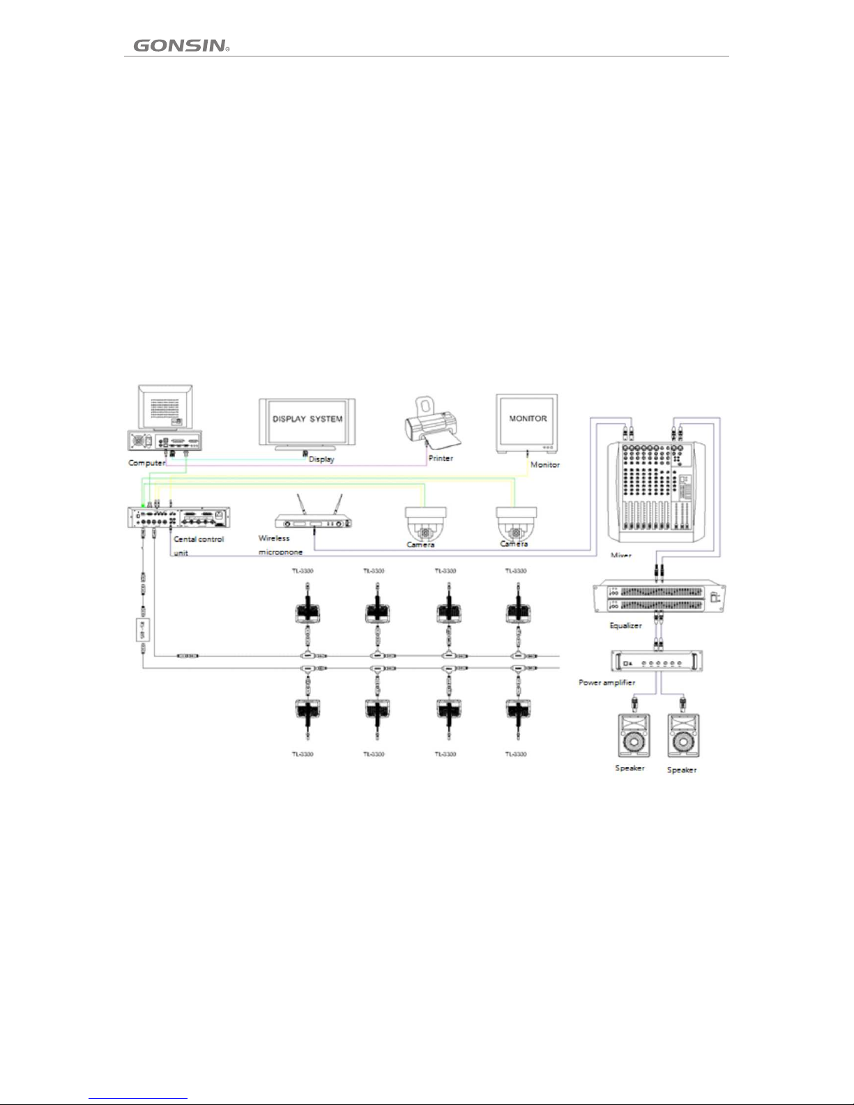
Syst em comp osi ti on:
TL-V 3300 sy stem is c ompos ed of c en tra l contr ol unit , basic c onfer ence un its (ch air man uni ts, del egate u nits) ,
comp uter (o ption al), co nfe re nce m anage ment so ftwar e (opti onal) , spe ed d ome c amera ( optio nal), a nd audi o
devi ces and d ispla y dev ic es.
(Con figur ation d iag ra m of th e confe rence s ystem )
Chapter 2 Central Control Unit of Digital Conference System
2.1 Central Contro l Unit
The ce ntral c ontro l unit pr ovi des sel ectab le micr ophon e modes : Auto, FI FO, O pe rat or and VO X (voic e-act ivate d
mode , for 420 0&560 0 ser ie s onl y), . It ha s DSP anti- feedb ack fun ction , and sup por ts i nte grate d use wit h autom atic
came ra trac king sy stem.
2.1.1 Functions and Indi cato rs of Ce ntral Control Unit
Over t he four -chan nel 8-p in or 1 3-pin i nterf ace, th e 3300 se ries sy stem ca n pro ce ss up t o 25 conf erenc e units p er
chan nel, an d a stand ard c en tra l contr ol unit c an proc ess up to 6 0 confe rence u nit s. T his num ber can b e incre ased
to 200 i f addin g two ext ens io n uni ts.
03 04

TL- 3300 Di gital C onfer ence Sy stems
Chapter 2 Central Control Unit of Digital Conference System
2.1 Central Contro l Unit
The ce ntral c ontro l unit pr ovi des sel ectab le micr ophon e modes : Auto, FI FO, O pe rat or and VO X (voic e-act ivate d
mode , for 420 0&560 0 ser ie s onl y), . It ha s DSP anti- feedb ack fun ction , and sup por ts i nte grate d use wit h autom atic
came ra trac king sy stem.
2.1.1 Functions and Indi cato rs of Ce ntral Control Unit
(Fro nt pane l of TL-Z3)
(Rea r panel o f TL -Z3)
Over t he four -chan nel 8-p in or 1 3-pin i nterf ace, th e 3300 se ries sy stem ca n pro ce ss up t o 25 conf erenc e units p er
chan nel, an d a stand ard c en tra l contr ol unit c an proc ess up to 6 0 confe rence u nit s. T his num ber can b e incre ased
to 200 i f addin g two ext ens io n uni ts.
Fron t panel
12. RS -485 CO M inter face (R S-4 85 TO CA MERA)
1. POW ER: pow er swit ch with i ndi ca tor
This i nterf ace has t wo pair s of co nn ect ion
term inals . It can be c onnec ted t o up t o 256 d ome
2. 128 *64mm b ackli ght L CD s cre en (blu e with wh ite
came ras or ke yboar ds wh ic h sup port RS -485
text )
PELC O-P96 00 and VI SCA-9 600 p rotoc ol.
3. Lef tward a nd righ tward a rro w keys of t he LCD
13. Ne twork i nterf ace (RJ -45 TO PC)
scre en (▶◀)
This R J-45 ne twork i nterf ace i s used fo r
4. Set ting ke y (SET)
conn ectin g to comp uter fo r ext en din g syste m
Pres s this ke y to ente r the men u int er fac e or exit
func tions ; setti ng IDs of c onf er enc e units a nd
the in terfa ce.
cond uctin g commi ssi on ing w ith the h elp of
5. Upw ard and d ownwa rd ar ro w key s of the LC D
soft ware in a r emote m anner ; and s ettin g camer a
scre en (▲▼)
trac king to e nable c hec k- in of c onfer ence un its
Use th e keys in dicat ed by ③ ④⑤ to s et spea king
and ex tend sp eakin g mod es o r vot ing fun ction s
mode a nd numb er of spe ake rs , and a djust v olume
(for d etail s, refe r to the so ftw ar e ins truct ion).
of lou dspea ker (vo lum e ad jus tment i s only
14. MI C input i nterf ace
appl icabl e for 560 0 ser ie s).
This i nterf ace is us ed for co nne cting t o wirel ess
6. Bas s contr ol knob ( BASS)
MICs a nd inte rpret er unit .
7. Treb le cont rol kno b (TREB LE)
15. Fo ur-ch annel 8 -pi n in ter face wi th fema le
8. Volu me cont rol kno b (VOL)
conn ector ( DELEG ATE S)
Note : Th is cont rol is on ly effe ct ive t o volum e of the
Over t his int erfac e, the ce ntr al c ont rol uni t can
non- balan ced aud io ou tp ut (R EC).
proc ess up to 1 5 confe ren ce u nit s per cha nnel.
For a st andal one sys tem, up t o 25 co nf ere nce
unit s can be pr ocess ed. For a s tan dard ce ntral
Rear p anel
cont rol uni t, up to 60 d elega te un its can b e
9. Two-ch annel AV vide o out pu ts 1/ 2 with RC A
proc essed . Th is numb er ca n be i ncr eased t o 200
conn ector ( VIDEO O UTPUT )
if add ing two e xtens ion u ni ts.
Note : Vi deo sig nals fr om th e tw o out puts ar e
16. 8- pin ext ensio n int er fac e with fe male co nnect or
cons isten t.
(ROU TE B)
10. Fo ur-ch annel v ide o in put s 1/2/3 /4 with R CA
This i nterf ace is us ed for ex pan ding th e centr al
conn ector ( VIDEO I NPUT)
cont rol uni t. After e xpans ion , a stand alone s ystem
can pr ocess u p to 200 co nfere nce u nits.
This i nterf ace tra nsmit s vid eo s ign als of au tomat ic
came ra trac king sy stem. m ax. f ou r dom e camer as
17. On e group o f balan ced a ud io ou tputs w ith RCA
can be c onnec ted. Nu mbe r 1 ca mer a is conn ected
conn ector ( LINE OU T)
to the v ideo in put 1; nu mber 2 ca mer a is
This i nterf ace is us ed for co nne cting t o the mix ing
conn ected t o the vid eo inpu t 2; nu mber 3 ca mera
cons ole or po wer amp lif ie r.
is con necte d to the vi deo inp ut 3; n um ber 4
Note : Durin g balan ced a ud io ou tput, v olume
came ra is con necte d to the vi deo i nput 4.
cont rol doe s not wor k.
11. RS-23 2 COM int erfac e (RS-2 32 TO PC)
18. Two gro ups of no n-bal anc ed audi o outpu ts with
This D B9-pi n COM int erfac e is us ed f or
RCA con necto r (REC)
conn ectin g compu ter for s yst em f unc tions ; setti ng
This i nterf ace is us ed for co nne cting t o the mix ing
IDs of c onfer ence un its and c ond uctin g
cons ole or po wer amp lif ie r.
comm issio ning wi th the he lp of s oftwa re; and
19. Po wer int erfac e (AC 110- 22 0V 50 Hz)
sett ing cam era tra cking t o ena bl e che ck-in o f
conf erenc e units a nd exte nd sp eakin g modes o r
voti ng func tions ( for det ail s, r efe r to the so ftwar e
inst ructi on).
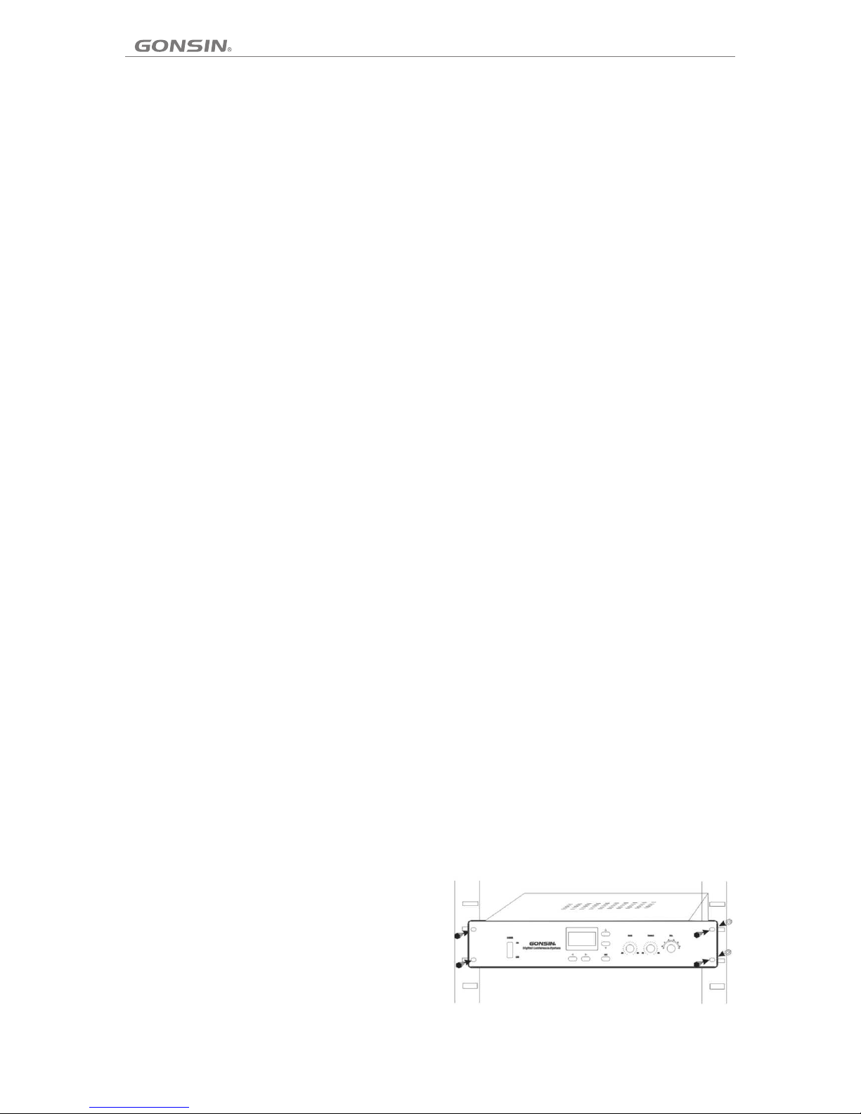
2.1.2 Installation of Centra l Cont rol Unit
(Fig ure 2.1 .2 Inst allat ion o f th e cen tral co ntrol u nit)
a. Ope n the pac kage an d check w het her all f ittin gs
are pr ovide d.
b. The cen tral co ntrol u nit i s 2U h igh , and the refor e it
can be i nstal led in a 19 -in ch r ack . Use scr ews to fi x
the un it to the r ack, as s hown in F igu re 2 .1. 2:
c. Con nect po wer cab le an d ot her d evice s to the un it.
2.1.3 Connection of Cent ral Co ntrol Unit
The ce ntral c ontro l unit ha s a fou r-cha nnel 8P -DIN
outp ut inte rface a nd a conf ere nce uni t has an 8P -
DIN fe male co nnect or. To conne ct t he ce ntral
cont rol uni t with th e confe ren ce unit , inser t the mal e
conn ector o f the 8P- T3 T-sha pe d cab le into t he
fema le conn ector o f the fir st co nf ere nce uni t, and
then c onnec t to the ou tput in ter fa ce of t he cent ral
cont rol uni t in seri al mo de .
If the d istan ce betw een the c ent ra l con trol un it and
conf erenc e unit is l ong , us e an 8P S-
03/0 5/10/ 15/20 /40 ext ens ion cab le that h as an 8P-
DIN ma le conn ector a nd an 8 P- DIN f emale
conn ector. I nterc onn ec t the f em ale c onnec tor of th e
exte nsion c able an d the 8 P- DIN m ale con necto r of
the ca ble fro m the con feren ce un it; and t hen ins ert
the ma le conn ector o f the ext ens ion cab le into t he
outp ut inte rface , as show n in Fi gure 2. 1.3.1 :
2.1.3.1 Conne cti on wi th conference Unit
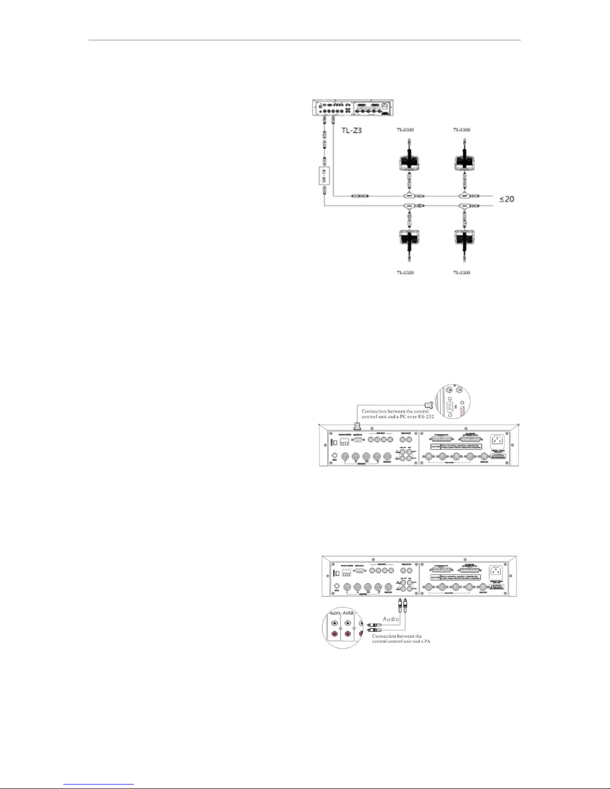
2.1.3.2 Conne cti on wi th PC
The ce ntral c ontro l unit is c onn ected w ith PC ov er the
RS-2 32 inte rface . Use a ser ial c able to c onnec t RS-
232 TO PC from t he cent ral con tro l un it to t he COM
inte rface f rom PC (g enera lly, to CO M1). Then , you
can ex pand sy stem fu nctio ns wi th soft ware. F igure
2.1. 3.2 sho ws the co nnect ion m ethod :
2.1.3.3 Conne cti on wi th Power Amplifier
The ce ntral c ontro l unit ha s one g roup of R CA
bala nced au dio out put ( LI NE OU T) and on e group o f
non- balan ced aud io ou tp ut (R EC). Aft er conn ectin g
the ce ntral c ontro l unit wi th th e PA sys tem, yo u can
ampl ify the s ound vo lum e of a s pea ker. This fu nctio n
is rea lized b y conne cti ng e ith er a grou p of RCA
bala nced au dio out put s “L INE O UT” or on e non-
bala nced au dio out put “ RE C” wi th the in put int erfac e
of the PA syst em. Ref er to Fig ure 2.1 .3. 3:
Note : Durin g balan ced a ud io ou tput, v olume c ontro l
does n ot work .
05 06
TL- 3300 Di gital C onfer ence Sy stems
2.1.3 Connection of Cent ral Co ntrol Unit
The ce ntral c ontro l unit ha s a fou r-cha nnel 8P -DIN
outp ut inte rface a nd a conf ere nce uni t has an 8P DIN fe male co nnect or. To conne ct t he ce ntral
cont rol uni t with th e confe ren ce unit , inser t the mal e
conn ector o f the 8P- T3 T-sha pe d cab le into t he
fema le conn ector o f the fir st co nf ere nce uni t, and
then c onnec t to the ou tput in ter fa ce of t he cent ral
cont rol uni t in seri al mo de .
If the d istan ce betw een the c ent ra l con trol un it and
conf erenc e unit is l ong , us e an 8P S03/0 5/10/ 15/20 /40 ext ens ion cab le that h as an 8PDIN ma le conn ector a nd an 8 P- DIN f emale
conn ector. I nterc onn ec t the f em ale c onnec tor of th e
exte nsion c able an d the 8 P- DIN m ale con necto r of
the ca ble fro m the con feren ce un it; and t hen ins ert
the ma le conn ector o f the ext ens ion cab le into t he
outp ut inte rface , as show n in Fi gure 2. 1.3.1 :
(Fig ure 2.1 .3.1 Co nne ct ion o f the cen tral co ntrol u nit
with c onfer ence un its)
2.1.3.1 Conne cti on wi th conference Unit
2.1.3.2 Conne cti on wi th PC
The ce ntral c ontro l unit is c onn ected w ith PC ov er the
RS-2 32 inte rface . Use a ser ial c able to c onnec t RS232 TO PC from t he cent ral con tro l un it to t he COM
inte rface f rom PC (g enera lly, to CO M1). Then , you
can ex pand sy stem fu nctio ns wi th soft ware. F igure
2.1. 3.2 sho ws the co nnect ion m ethod :
(Fig ure 2.1 .3.2 Co nnect ion o f th e cen tral co ntrol u nit
with P C)
2.1.3.3 Conne cti on wi th Power Amplifier
The ce ntral c ontro l unit ha s one g roup of R CA
bala nced au dio out put ( LI NE OU T) and on e group o f
non- balan ced aud io ou tp ut (R EC). Aft er conn ectin g
the ce ntral c ontro l unit wi th th e PA sys tem, yo u can
ampl ify the s ound vo lum e of a s pea ker. This fu nctio n
is rea lized b y conne cti ng e ith er a grou p of RCA
bala nced au dio out put s “L INE O UT” or on e nonbala nced au dio out put “ RE C” wi th the in put int erfac e
of the PA syst em. Ref er to Fig ure 2.1 .3. 3:
Note : Durin g balan ced a ud io ou tput, v olume c ontro l
does n ot work .
(Fig ure 2.1 .3.3 Co nnect ion o f TC -Z3 wit h PA)
2.1.3.4 Conne cti on wi th Repeater
If a sys tem wil l be wire d long or a m ass iv e num ber of
conf erenc e units a re requ ire d, syst em
comm unica tion wi ll be co me un stabl e. In thi s case,
use an R S-485 r epeat er. Co nv ent ional ly, this dev ice
is ins talle d betwe en th e ex ten sion ca ble of th e centr al
cont rol uni t and the f irst co nfe re nce u nit.
To conne ct the ce ntral c ontro l uni t an d the r epeat er,
conn ect the m ale con necto r of an 8 PS e xte nsion
cabl e to the ce ntral c ontro l uni t; a dd an 8 P2-01
exte nsion c able be twe en t he fe male co nnect or of the
8PS ex tensi on cabl e and the 8 -pi n male co nnect or of
the re peate r; use a T-sha ped c ab le to c onnec t the
repe ater an d the con feren ce un it. Ref er to Fig ure
2.1. 3.4:
Note : For the i nstal latio n dir ectio n of the re peate r,
refe r to the in struc tion on t he re pe ate r.
(Fig ure 2.1 .3.4 Co nne ct ion o f the cen tral co ntrol u nit
with r epeat er)
Func tions o f indic ators :
POWE R: Powe r indic ator: s tea dy o n ind icate s norma l
stat e; off indi cates p owe r fa ilu re.
MXD: F ault in dicat or: ste ady o n in dic ates sh ort cir cuit
or oth er fail ure; fl ashin g ind icate s norma l
comm unica tion.
RXD: S ignal r eceiv ing i nd ica tor: st eady on i ndica tes
rece iving f ailur e; flas hin g indic ates no rmal
comm unica tion.
TXD: S ignal t ransm ittin g ind ic ato r: stea dy on
indi cates t ransm ittin g fai lu re; f lashi ng indi cates
norm al comm unica tio n.
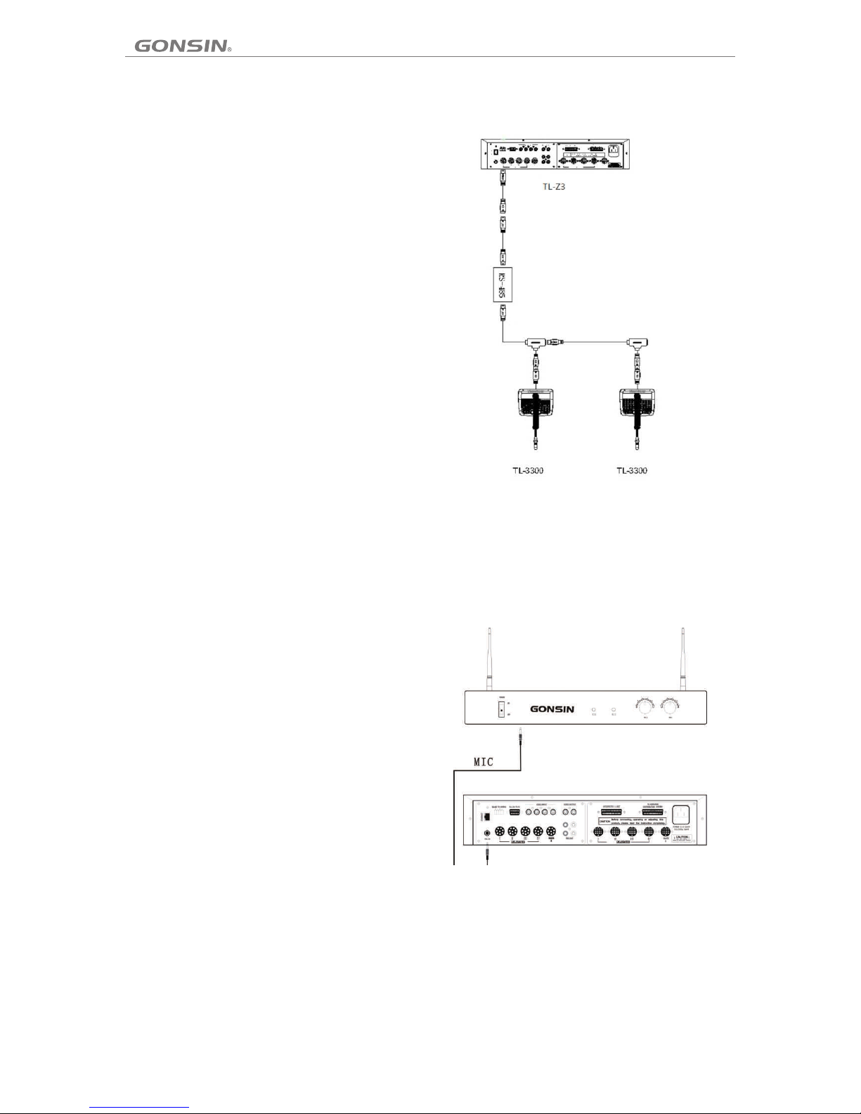
2.1.3.5 Conne cti on wi th Wireless MIC
Conn ect the c entra l contr ol un it with t he wire less MI C
over t he MIC in terfa ce. Use t he au di o cab le with M IC
conn ector f rom the w irele ss MI C re cei ver to co nnect
the ce ntral c ontro l unit. T he f igu re show s the
conn ectio n metho d:
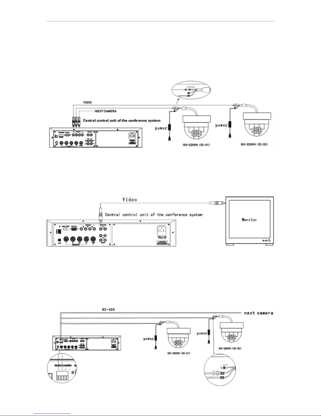
2.1.3.6 Conne cti on wi th Camera
The ce ntral c ontro l unit ca n be co nnect ed with d ome cam eras th at supp ort PEL CO- P or S ON Y VISCA pr otoco l. It is
baud r ate is 96 00. Use rs shou ld se lect qu alifi ed dome c amera s that su pport e ith er o f the p rotoc ols.
The fo llowi ng will d esc ri be re spect ively h ow to con nect GX -2200 H camer a (de ve lop ed by GON SIN) an d a SONY
D70 ca mera to t he cent ral con tro l un it.
a. Con nect GX -2200 H camer a (PE LC O-P ) to the ce ntral c ontro l unit.
Chec k if the pr otoco l DIP and a dd res s DIP have be en set fo r the dom e camer a (for de tai le d set ting, r efer to t he
came ra user g uide) . By defa ult , th e pro tocol D IP and baud r ate hav e been se t in fact ory ; an d add ress st arts fr om
numb er 1.
1. Con nect th e camer a to the ce ntr al c ont rol uni t via a vid eo cabl e.
Amon g the thr ee grou ps of wir ing f rom the c amera , two gro ups of wi ring is u sed for c onn ec tin g to the ce ntral c ontro l
unit ( power o f the cam era is su ppl ied dir ectly f rom the c ontro l room) . One gro up of w ir ing i s the 75Ω AV vide o
wiri ng, its R CA conne cto r co nne cts the c amera v ideo ou tput wi th the vi deo inp ut of t he c ent ral con trol un it, whe re,
numb er 1–in put 1; nu mbe r 2– inp ut 2. The cam era tra cking o f the pan orami c pre se t pos ition a nd the ch airma n unit
are co mplet ed by num ber 1 c am era . Refer t o the fol lowin g figur e:
2. Con nect mo nitor o r video m atr ix to the c entra l contr ol unit .
The ce ntral c ontro l unit ha s a 4x2 a uto-c ontro l camer a matri x, and th e video o utp ut s are R CA conne ctors , from
whic h you can u se a 75ΩAV vid eo ca bl e to co nnect t he disp lay dev ices, e .g. mon itor, AV dis tr ibu tor, or ma trix.
Refe r to the fo llowi ng figu re:
3、Conn ect the c amera t o the cen tra l contr ol unit v ia the co mmuni catio n cable t o con tr ol th e camer a.
The ot her gro up of wir ing b et wee n the cam era and t he cent ral con trol un it is rea liz ed b y RS- 485 com munic ation
cabl es. Gen erall y, it i s adv is abl e to use a ne twork c able as t he comm unica tion ca ble . Selec t a pair of w ires fr om the
cabl e and con nect th em to the R S-4 85 “+” an d “-” of th e centr al cont rol uni t respe cti ve ly. Refe r to the fo llowi ng
figu re:
07 08
Centr al c on tr ol u nit
Centra l co nt ro l unit
1. Con nect th e camer a to the ce ntr al c ont rol uni t via a vid eo cabl e.
Amon g the thr ee grou ps of wir ing f rom the c amera , two gro ups of wi ring is u sed for c onn ec tin g to the ce ntral c ontro l
unit ( power o f the cam era is su ppl ied dir ectly f rom the c ontro l room) . One gro up of w ir ing i s the 75Ω AV vide o
wiri ng, its R CA conne cto r co nne cts the c amera v ideo ou tput wi th the vi deo inp ut of t he c ent ral con trol un it, whe re,
numb er 1–in put 1; nu mbe r 2– inp ut 2. The cam era tra cking o f the pan orami c pre se t pos ition a nd the ch airma n unit
are co mplet ed by num ber 1 c am era . Refer t o the fol lowin g figur e:
2. Con nect mo nitor o r video m atr ix to the c entra l contr ol unit .
The ce ntral c ontro l unit ha s a 4x2 a uto-c ontro l camer a matri x, and th e video o utp ut s are R CA conne ctors , from
whic h you can u se a 75ΩAV vid eo ca bl e to co nnect t he disp lay dev ices, e .g. mon itor, AV dis tr ibu tor, or ma trix.
Refe r to the fo llowi ng figu re:
3、Conn ect the c amera t o the cen tra l contr ol unit v ia the co mmuni catio n cable t o con tr ol th e camer a.
The ot her gro up of wir ing b et wee n the cam era and t he cent ral con trol un it is rea liz ed b y RS- 485 com munic ation
cabl es. Gen erall y, it i s adv is abl e to use a ne twork c able as t he comm unica tion ca ble . Selec t a pair of w ires fr om the
cabl e and con nect th em to the R S-4 85 “+” an d “-” of th e centr al cont rol uni t respe cti ve ly. Refe r to the fo llowi ng
figu re:
TL- 3300 Di gital C onfer ence Sy stems

b. Con nect th e SONY D70 ca mer a (V ISC A) to the c entra l contr ol unit .
Befo re conn ectin g the SON Y ca mer a EVI-D 70/D7 0P, set the com munic ation m ode t o RS -42 2 and bau d rate to
9600 bps for t he came ra. The R S- 485 “ +” conn ects wi th “RXD I N-“ and “ -” with “ RXD IN+ ”. Re fe r to th e follo wing
figu re:
Note : By defa ult, th e first D 70 ca me ra co nnect ed to
the ce ntral c ontro l uni t is n umb er 1 came ra; the
came ra casc aded to t he nu mb er 1 ca mera is n umber
2 came ra; and t hen num ber 3 cam era a nd numb er 4
came ra. Whe n using t he soft war e fo r the s ettin g,
make s ure the I Ds are co rresp ond ing wit h the
came ras.
Note : For cam era tra cking s ett in g, re fer to th e instr uctio n of the so ftwar e.
2.1.3.7 Conne cti on wi th Speed Dome Controll er
Chec k if prot ocol an d bau d ra te ha ve been s et for th e speed d ome con troll er GX-K B01 ( fo r det ails, r efer to t he
inst ructi on deli vered w ith t he spee d dome co ntrol ler). U se a two- core tw ist ed p air c able to c onnec t the “48 5+” and
“485 -” of the s peed do me cont rol ler to th e “485+ ” and “48 5-” of th e centr al cont rol u ni t (be fore th is oper ation , make
sure t he RS48 5 contr ol cabl e of th e ca mer a has bee n conne cted to t he RS48 5 contr ol ca bl e of th e centr al cont rol
unit ). Refe r to the fo llowi ng fi gu re:
You ca n use the s ame met hod to co nne ct t he sp eed dom e contr oller t o the cam era via 4 85 co nt rol c able.
2.1.4 Setting and Operation of C entr al Control Unit
The LC D scree n has fiv e keys: ▲, ▼, ▶, ◀, a nd for a mi nute.
“SET ”. After p ressi ng the SE T ke y and e nteri ng the
sett ing mod e, text w ill be di spl ayed on a c ontra st
back groun d. The left war d an d rig htwar d arrow k eys
are us ed to set s elect ion and e xit , as show n in
Figu res 2(a ) and 2(b ). The up wa rd an d downw ard
arro w keys ar e used to s witch m enu a fter th e menu is
acti vated ( as show n in Figu res 2 (a) and 2 (c), an d
used t o chang e setti ng afte r set m en u is ac tivat ed (as
show n in Figu res 2(b ) and 2 (d ).
Duri ng sett ing, if t here is n o ope ratio n withi n one
minu te, or th e menu is a ctiva ted , pr ess “ SET” ke y to
ente r “Curr ent Sta tus” in ter fa ce. O n this in terfa ce,
the ba cklig ht will b e tur ne d off if th ere is no o perat ion
09 10

2.1.4 Setting and Operation of C entr al Control Unit
The LC D scree n has fiv e keys: ▲, ▼, ▶, ◀, a nd for a mi nute.
“SET ”. After p ressi ng the SE T ke y and e nteri ng the
sett ing mod e, text w ill be di spl ayed on a c ontra st
1. Sta rtup in terfa ce:
back groun d. The left war d an d rig htwar d arrow k eys
The ce ntral c ontro l unit wi ll in itial ize aft er it is
are us ed to set s elect ion and e xit , as show n in
powe red on. I nterf ace 1 sho ws th e initi aliza tion
Figu res 2(a ) and 2(b ). The up wa rd an d downw ard
inte rface .
arro w keys ar e used to s witch m enu a fter th e menu is
acti vated ( as show n in Figu res 2 (a) and 2 (c), an d
used t o chang e setti ng afte r set m en u is ac tivat ed (as
show n in Figu res 2(b ) and 2 (d ).
2. Cur rent st atus in terfa ce:
Afte r initi alizi ng, the L CD sc reen sh ows cur rent
stat us, inc ludin g Acti ve m ics , Mode, a nd DSP, as
show n in inte rface 2 . Press “ SET ” to e nte r the Set
inte rface .
3. Set i nterf ace:
The Se t inter face ha s three p age s, wher e you can
set Act ive mic s, Mode , DSP, Unit v ol , Uni t ID No,.
Lang uage, C ontra st
The sy mbols ▲, ▼, ◄ , ►, and ◆ in dicat e upw ar d,
down ward, l eftwa rd, rig htw ard, an d page up /down .
For ex ample , in inte rface 3 , pre ss t he do wnwar d
arro w key to en ter int erfac e 4; pr es s the d ownwa rd
arro w key aga in to ent er in te rfa ce 5; on th e contr ary,
pres s the upw ard arr ow key to g o bac k to i nte rface 4
and pr ess the u pward a rro w ke y aga in to go ba ck to
inte rface 3 .
Duri ng sett ing, if t here is n o ope ratio n withi n one
minu te, or th e menu is a ctiva ted , pr ess “ SET” ke y to
ente r “Curr ent Sta tus” in ter fa ce. O n this in terfa ce,
the ba cklig ht will b e tur ne d off if th ere is no o perat ion
Figu re 2(a)
Figu re 2(b)
Figu re 2(c)
Figu re 2(d)
Inte rface 1
Inte rface 2
Inte rface 2
TL- 3300 Di gital C onfer ence Sy stems

Inte rface 4
Inte rface 5
③ DSP is use d to turn O N or OFF th e funct ion f or
acou stic fe edbac k preve nti on.
④ Unit Vo l at inte rface 7 i s used to a dju st the
volu me leve l 00-31 f or al l un its o r singl e unit.
Choo se the un it numb er an d th en ad just th e
sett ing. (T his fun ction f or 56 00 s eri es only.)
Unit I D No. is us ed to rew rite th e uni t nu mbe r or add
a new nu mber, wi thin th e ran ge 0 002 -9999
excl uding t he numb ers o f 25 0-2 57 and 50 0-514 ..
Use up /down (▲/▼) b utton t o selec t the u ni t num ber
and pr ess SET to co nfirm . Any un wr ita ble num ber
① Acti ve mics : 1/2/3 /4 is use d to se t 1/ 2/3 /4
will s kip to th e next wr itabl e num ber. If ID N o. is
micr ophon es whic h can b e ac tiv e simul taneo usly.
writ able, i nterf ace 8 wil l dis play, and re write I D; if ID
Note : Th is sett ing lim its the n umb er of spe akers .
No. is n ot conf irmed , press l eft wa rd ar row key t o exit
Up to 4 de legat e units c an be act iva ted at th e
and ba ck to int erfac e 4; If ID No . is co nf irm ed,
same t ime (ex cludi ng chai rma n unit an d vice
inte rface 9 w ill dis pla y, th en b ack t o inter face 4
chai rman un it).
auto matic ally. Unit n umb er w ill a dd 1 auto matic ally
② Mode i s used to s elect m icrop hon e mode VO X,
for wr iting t he next n umber.
FIFO , AUTO, and OP ERATO R, wher e, AUTO
indi cates a ny micr oph on e can b e activ e withi n
the pr eset nu mber li mit; FI FO in di cat es firs t
acti ve micr ophon e wil l be s wit ched off
auto matic ally wh en the nu mbe r of acti ve mics
exce eds the p reset n umber l imi t..; OP ERATO R
mean s any mic ropho ne mo re t han t he pres et
numb er limi t needs t o reque st to t al k, an d can be
acti vated a utoma tical ly wh en any ac tive
micr ophon e is turn ed off. . If V OX is s el ect ed,
pres s the rig htwar d arrow k ey to e nt er in terfa ce 6
and se t sensi tivit y ( high/ M id/ Lo w) of a ll unit s,
sens itivi ty can be a djust ed fo r si ngl e unit (v alue
rang e: 0002 ~9999 ; this se tti ng need s elect t he
mic ID f irst, t hen set s ensit ivi ty ), an d MIC tim eout is u sed to se t time li mit for 2 , 30, 6 0, 1 20, 1 80
seco nds. Wh en no aud io in pu t is de tecte d,
micr ophon e will be o ff a uto ma tic ally. (VOX f or
4200 &5600 s eries o nly ). Af ter s ettin g, pres s the
left ward ar row key t o retur n to in te rfa ce 3.
⑤ Lang uage is u sed to se t dis pl ay la nguag e of the
cent ral con trol un it and al l con feren ce unit s. EN
for En glish a nd CN for C hin es e can b e selec ted..
Pres s the rig htwar d arrow k ey to e nter in terfa ce
10 and s et lang uage fo r sin gl e uni t. Sele ct the
numb er of a uni t first a nd then s et it s la ngu age.
Inte rface 6
Inte rface 7
(Thi s funct ion for 4 200&5 600 s eries o nly)
⑥ Cont rast is u sed to ad just th e LCD c ontra st for
cent ral con trol un it or any c onf erenc e unit, p ress
righ tward a rrow ke y to ente r int erfac e 11, c entra l
cont rol uni t contr ast set tin g ra nge i s withi n 00-32 .
Choo se Rese t and pre ss Se t to a dju st the ce ntral
cont rol uni t contr ast as th e def au lt se tting .
Unit i s used to a djust t he cont ras t fo r any s ingle
conf erenc e unit. C hoo se u nit n umber ( withi n
0002 -9999 ),the n "+" o r "- ", pr ess Set t o adjus t the
cont rast se tting . Choos e Res et a nd pr ess Set t o
adju st the un it cont rast as t he de fa ult s ettin g.
Inte rface 8
Inte rface 9
2.2 Extension Unit
2.2.1 Functions and Indi cato rs of ZJ -KR
11 12

(Thi s funct ion for 4 200&5 600 s eries o nly)
Exce pt for Cu stom se tting f or VO X se nsi tivit y, Un it
vol, l angua ge, Uni t ID No, an d con trast , other s ettin g
will b e autom atica lly s av ed an d will no t be lost i n case
of pow er inte rrupt .
4. Onl ine Sta tus int erfac e:
If the c entra l contr ol unit i s in on line st atus, a n Onlin e
Stat us inte rface a ppear s, on ly DSP (squ ealin g
supp ressi on) is wo rki ng a s int erfac e 12.. Wh en ther e
is no op erati on with in on e mi nut e, the ba cklig ht is
turn ed off and ac tive st atu s is o ff . Onl y when pr ess
SET agai n to acti vate th e cen tr al co ntrol u nit, th e
⑥ Cont rast is u sed to ad just th e LCD c ontra st for
DSP can be e nable d. Curr ent S ta tus w ill be di splay ed
cent ral con trol un it or any c onf erenc e unit, p ress
when c entra l contr ol un it i s dis conne cted wi th PC.
righ tward a rrow ke y to ente r int erfac e 11, c entra l
cont rol uni t contr ast set tin g ra nge i s withi n 00-32 .
Choo se Rese t and pre ss Se t to a dju st the ce ntral
cont rol uni t contr ast as th e def au lt se tting .
Unit i s used to a djust t he cont ras t fo r any s ingle
conf erenc e unit. C hoo se u nit n umber ( withi n
0002 -9999 ),the n "+" o r "- ", pr ess Set t o adjus t the
cont rast se tting . Choos e Res et a nd pr ess Set t o
adju st the un it cont rast as t he de fa ult s ettin g.
Inte rface 1 0
Inte rface 11
Inte rface 1 2
2.2 Extension Unit
2.2.1 Functions and Indi cato rs of ZJ -KR
TL- 3300 Di gital C onfer ence Sy stems

Fron t panel :
3. Ext ensio n outpu t inter fac e 8P S/1 3PS
1. POW ER: pow er swit ch with a r ed in di cat or
Note : Th ese int erfac es ar e us ed fo r conne cting w ith
conf erenc e unit or t he next e xte nsion u nit.
Rear p anel:
4. Out put int erfac es (8PS /13 PS ) of co nfere nce uni ts
2. Ext ensio n input i nterf ace 8 PS /13 PS
(1~3 ; total : 3 chann els)
Note : Th ese int erfac es ar e us ed fo r conne cting
5. Pow er inpu t inter face
with t he cent ral con trol un it or t he p rec eding
exte nsion u nit.
2.2.2 Installation of Extens ion Un it
The ex tensi on unit i s 2U high , and t heref ore it ca n be inst alled i n a 19-in ch rack . Use s cr ews t o fix the e xtens ion
unit t o the rac k.
Inst allat ion of th e exten sio n unit
2.2.3 Connection of Exte nsio n Unit
ZJ-K R can be co nnect ed to the c ent ra l con trol un it over a n 8P2-0 1cabl e. After e xte ns ion , a stand alone c entra l
cont rol sys tem can p roces s up to 2 00 c onf erenc e units . Befor e addin g 8-pin c onf er enc e units , use an 8P 2-01 ca ble
to con nect th e centr al cont rol u nit (RO UTE OUT ) and the e xtens ion uni t (ROUT E IN). Th e ex ten sion un its can b e
casc aded as w ell. Add iti on al ex tensi on unit c an be con necte d over RO UTE OUT. Th e fo llo wing fi gure sh ows the
conn ectio n metho d:
13 14

2.2.3 Connection of Exte nsio n Unit
ZJ-K R can be co nnect ed to the c ent ra l con trol un it over a n 8P2-0 1cabl e. After e xte ns ion , a stand alone c entra l
cont rol sys tem can p roces s up to 2 00 c onf erenc e units . Befor e addin g 8-pin c onf er enc e units , use an 8P 2-01 ca ble
to con nect th e centr al cont rol u nit (RO UTE OUT ) and the e xtens ion uni t (ROUT E IN). Th e ex ten sion un its can b e
casc aded as w ell. Add iti on al ex tensi on unit c an be con necte d over RO UTE OUT. Th e fo llo wing fi gure sh ows the
conn ectio n metho d:
(Con necti on diag ram o f 8- pin c onfer ence un its)
TL- 3300 Di gital C onfer ence Sy stems

Chapter 3 Conference Unit TL-3300
3.1 Overview
The TL-3 300 con feren ce un it p rov ides ba sic fun ction s: incl uding s pea ki ng, l isten ing, at tenda nce reg istra tion an d
auto matic c amera t racki ng.
The co nfere nce uni ts incl ude c hairm an unit a nd dele gate un it. The onl y diffe re nce b etwee n them is t hat the
chai rman un it has an e xtra pr ior ity (PR IO) key. By us ing sof tware , the del egate u nit c an b e set a s vice ch airma n
unit , which w ill not b e lim it ed by t he pres et numb er of act ive mic ropho nes and s pea ki ng mo de. Up to 1 0 vice
chai rmen ca n be set.
3.2 Functions and In dica tors o f TL-3 300
Figu re 3.2 TL-V X3300
Fron t panel :
Rear p anel:
1. Swi tch (MI C ON/OF F)
7. 0.5 m cable w ith an 8S -0.5 fe mal e conne ctor; a
basi c unit is e quipp ed wi th a 0 .5m 8 -pin ca ble wit h
2. Red p riori ty key ex clusi ve fo r ch air man uni t
fema le conn ector w hic h sh oul d be inse rted in to a
(PRI OR); pr ess thi s key to cl ose a ll a cti ve dele gate
T-sha ped cab le.
unit s
8. Del egate u nit con nec ti on ca ble tru nking . No need
Note : Deleg ate uni t doesn 't ha ve PRIO R funct ion,
to fix t he dele gate un it conn ect ion cab le in the
thus d oes not h ave thi s key.
trun king bu t just le ave it in t he ho le in the t able to
3. Bui lt-in l oudsp eak er ( 4Ω3W)
hide t he cabl e.
Left -side p anel:
4. Volu me cont rol (VO L)
5. Audi o outpu t inter face, a 3 .5m m ja ck th at is for
conn ectin g to a reco rding d evi ce to do re cordi ng
6. Hea dphon e outpu t inter fac e, a 3.5m m jack
3.3 Installation a nd Con nect ion of T L-3300
3.3.1 Connection with T-shap ed Cable
To conne ct the T-sha ped cab le (8 P- T3) t o the con feren ce unit , inser t the fem ale con nec tor of th e 0.5m ca ble fro m
the co nfere nce uni t into th e mal e conne ctor of o ne end fr om the T-sha ped cab le, t he n ins ert the m ale con necto r of
anot her end f rom thi s T-s hap ed c abl e into th e femal e conne ctor of t he prev iou s T-s ha ped c able. R efer to t he
foll owing f igure :
3.3.2 Connection with th e Cent ral Control Unit
At the c onfer ence si te, the d ist an ce be tween t he firs t confe rence u nit and t he ce nt ral c ontro l unit is n ormal ly far, so
the ex tensi on cabl e (8P S- 10/ 15/20 /40) wi ll be nee ded to co nnect t hem. Th e ma le co nnect or of the e xtens ion cab le
is con necte d to the “D ELEGAT ES ” int erfac e from th e centr al cont rol uni t at the ra ck, and i ts fe ma le co nnect or is
conn ected t o the mal e con ne cto r of the fi rst T-shap ed cabl e at the co nfere nce sit e. Re fe r to th e follo wing fi gure:
3.3.3 Connection with Ex tens ion Unit
Conn ectio n of the co nfere nce u nit wit h the ext ensio n unit is s imila r to that b etw ee n the c onfer ence un it and th e
cent ral con trol un it. Not e tha t th e ext ensio n cable o f the con feren ce unit s hal l on ly co nnect t o the thr ee
“DEL EGATES” in terfa ces. “R OUT E A IN” and “RO UTE B OUT ” shall c onnec t to the pr ecedi ng ce nt ral c ontro l unit
15 16

3.3 Installation a nd Con nect ion of T L-3300
3.3.1 Connection with T-shap ed Cable
To conne ct the T-sha ped cab le (8 P- T3) t o the con feren ce unit , inser t the fem ale con nec tor of th e 0.5m ca ble fro m
the co nfere nce uni t into th e mal e conne ctor of o ne end fr om the T-sha ped cab le, t he n ins ert the m ale con necto r of
anot her end f rom thi s T-s hap ed c abl e into th e femal e conne ctor of t he prev iou s T-s ha ped c able. R efer to t he
foll owing f igure :
3.3.2 Connection with th e Cent ral Control Unit
At the c onfer ence si te, the d ist an ce be tween t he firs t confe rence u nit and t he ce nt ral c ontro l unit is n ormal ly far, so
the ex tensi on cabl e (8P S- 10/ 15/20 /40) wi ll be nee ded to co nnect t hem. Th e ma le co nnect or of the e xtens ion cab le
is con necte d to the “D ELEGAT ES ” int erfac e from th e centr al cont rol uni t at the ra ck, and i ts fe ma le co nnect or is
conn ected t o the mal e con ne cto r of the fi rst T-shap ed cabl e at the co nfere nce sit e. Re fe r to th e follo wing fi gure:
3.3.3 Connection with Ex tens ion Unit
Conn ectio n of the co nfere nce u nit wit h the ext ensio n unit is s imila r to that b etw ee n the c onfer ence un it and th e
cent ral con trol un it. Not e tha t th e ext ensio n cable o f the con feren ce unit s hal l on ly co nnect t o the thr ee
“DEL EGATES” in terfa ces. “R OUT E A IN” and “RO UTE B OUT ” shall c onnec t to the pr ecedi ng ce nt ral c ontro l unit
TL- 3300 Di gital C onfer ence Sy stems

and th e next ex tensi on unit r esp ectiv ely. Refer t o the fol lowin g figur e:
3. 4 Operation of TL-3 300
Afte r all wir es are co nnect ed, p ow er on a ll devi ces. Wh en the ce ntral c ontro l uni t ma kes a ” tick” s ound, t he
conf erenc e unit ca n be op er ate d.
1. For 3 300 ser ies con feren ce un its, pr ess “MI C ON/OF F” to ena ble the m, that i s, pres s . Th e ind ic ato rs of the
key an d MIC rin g are lit o n, indi cat ing tha t parti cipan ts can sp eak.
2. The con feren ce unit h as a bu il t-i n louds peake r. Gener ally, this l oudsp eak er i s ena bled wh en the co nfere nce sit e
is not e quipp ed with l oud sp eak er devi ces. Pu sh the kn ob indi cated b y ⑤ in Figu re 3. 2 to i ncr ease vo lume. I f the
conf erenc e site ha s been eq uip ped wit h a louds peake r syste m, it is ad visab le to d ec rea se loud speak ers of al l
conf erenc e units t o lowes t lev el and di sable t he loud speak ers; ot herwi se, o ns ite a coust ic syst em may be
inte rfere d.
3. The cha irman u nit has a u niq ue “ PRI OR” red k ey. To inte rrupt a s peake r, pre ss t his k ey and al l deleg ate uni ts are
disa bled.
4.1 Cables
4.1.1 Connection Cable ( 8P-T 3) for Conference Unit
Technic al indi cator s
Colo r: blac k
Type: 8 PS
Conn ector : male co nne ct or x 2; f em ale c onnec tor x 1
Leng th: 1.5 + 1 .2m
Note : Gener ally, each c onf er enc e unit is c onfig ured
with o ne such c able.
4.1.2 Extension Cable (8 PS-0 3/05/10/15/20/40)
Technic al indi cator s
Colo r: blac k
Type: 8 PS
Conn ector : male co nne ct or x 1; f em ale c onnec tor x 1
Leng th: 3m, 5 m, 10m, 1 5m, 20m , 40m
Note : Confi gurat ion i s su bje ct to num ber of
conf erenc e units .
4.1.3 Serial Interface Cable ( RS-2 32-5)
Technic al indi cator s
Colo r black
Type DB 9
Conn ector f emale c onn ec tor x 2
Leng th 5m
Note : Cable o f this ty pe is con fig ured fo r the cen tral
cont rol uni t with so ftwar e.
17 18
4.1.4 Extension Cable (8 P2-0 1)
Technic al indi cator s
Colo r: blac k
Type: 8 P
Conn ector : male co nne ct or x 2
Leng th: 1m
Note : Each ce ntral c ontro l uni t or repe ater is
conf igure d with on e suc h ca ble .

Chapter 4 Cables and Configuration
4.1 Cables
4.1.1 Connection Cable ( 8P-T 3) for Conference Unit
Technic al indi cator s
Colo r: blac k
Type: 8 PS
Conn ector : male co nne ct or x 2; f em ale c onnec tor x 1
Leng th: 1.5 + 1 .2m
Note : Gener ally, each c onf er enc e unit is c onfig ured
with o ne such c able.
4.1.2 Extension Cable (8 PS-0 3/05/10/15/20/40)
Technic al indi cator s
Colo r: blac k
Type: 8 PS
Conn ector : male co nne ct or x 1; f em ale c onnec tor x 1
Leng th: 3m, 5 m, 10m, 1 5m, 20m , 40m
Note : Confi gurat ion i s su bje ct to num ber of
conf erenc e units .
4.1.3 Serial Interface Cable ( RS-2 32-5)
Technic al indi cator s
Colo r black
Type DB 9
Conn ector f emale c onn ec tor x 2
Leng th 5m
Note : Cable o f this ty pe is con fig ured fo r the cen tral
cont rol uni t with so ftwar e.
TL- 3300 Di gital C onfer ence Sy stems
4.1.4 Extension Cable (8 P2-0 1)
Technic al indi cator s
Colo r: blac k
Type: 8 P
Conn ector : male co nne ct or x 2
Leng th: 1m
Note : Each ce ntral c ontro l uni t or repe ater is
conf igure d with on e suc h ca ble .

4.2 Repeater
Technic al indi cator s
Colo r black
Type: R S-485 r epeat er
Inte rface : 8-pin f emale c onn ec tor x 2 ; 13-pi n femal e
conn ector x 2
Dime nsion : 110 ×64×3 8mm
Mate rial: a lumin um
Note : If syst em wiri ng leng th ex ce eds 5 0m, add a
repe ater (g enera lly, thi s de vic e is conn ected
afte r an exte nsion c able or i n the m iddle o f the
bus) .
4.3 Ground Socket
Technic al indi cator s
Mode l GX-8&1 3S
Colo r: gold en
Type: g round s ocket
Inte rface : 8-pin f emale c onn ec tor x 1 ; 13-pi n femal e
conn ector x 1
Area o f panel : 120×1 20m m
Hole c leara nce: 83 .5m m
Mate rial of p anel: c opper
Dime nsion : 100×1 00× 55 mm
Mate rial of b ottom : metal
:
5.1 System Connect ion
GOSI N digit al conf erenc e sys te m has a s imple s truct ure and e xtens ible ha rdw ar e. The sy stem is e asy to in stall ,
and sy stem ma inten anc e do es no t need mu ch skil l. Comm on tech nicia ns can co ndu ct this w ork aft er a shor t perio d
of tra ining . Confe ren ce u nit s are con necte d in a “han d-in- hand” m ode and t hey a re fina lly con necte d to the ce ntral
cont rol uni t with sp eci al 8 -pi n exten sion ca bles.
This c hapte r mainl y des cr ibe s how to co nnect t he conf erenc e syste m.
5.1.1 Principle of Conne ctio n
In a dig ital co nfere nce sys tem , co nfe rence u nits ar e power ed by the c entra l con tr ol un it; the refor e, the nu mber of
conf erenc e units t hat the c ent ra l con trol un it can pr ocess i s subje ct to the p owe r su ppl y capab ility o f the cen tral
cont rol uni t. The cent ral c on tro l unit ha s a 4-cha nnel ou tput in terfa ce. For t he 32 00 s eri es cent ral con trol un it, eac h
chan nel can p roces s up to 1 5 co nfe rence u nits an d a stand alone c entra l contr ol un it can pr ocess u p to 60
conf erenc e units . If an ext ens io n uni t is adde d, this n umber c an be inc rease d to 12 0; i f two e xtens ion uni ts are
adde d, this n umber c an be i nc rea sed to 20 0. Betw een the c entra l contr ol unit a nd ex te nsi on unit , and bet ween
exte nsion u nits, 8 -pi n ca ble s are add ed to con nect th em in ser ial mod e.
If the d istan ce betw een the c ent ra l con trol un it and co nfere nce uni ts, and b etw ee n con feren ce unit s excee ds 1.5m ,
use ex tensi on cabl es to con nec t them. N ote tha t exten sion ca bles ha ve resi sta nc e, us ing the m will re duce th e
numb er of con feren ce un it s whi ch the ce ntral c ontro l unit ca n proce ss. The rel ati onshi p is show n in the fo llowi ng
tabl e:
Dist ance be tween t he ce nt ral c ontro l unit an d the fir st
conf erenc e unit
40m (i n norma l use con dit io n) 15
60m 14
80m 13
100m 12
5.1.2 8P-T3 Cable
The to tal len gth of th is cabl e is 1. 5+1.2 m. The 1.5m s ectio n carri es an 8-p in male c onn ector f or inte rconn ectin g
with t he fema le conn ector o f an ex tensi on cabl e or the pr ecedi ng 8P-T 3 cable ; the 1 .2 m sec tion ca rries a n 8-pin
male c onnec tor as we ll fo r in ter conne cting w ith the c onfer ence un it, and a n fem al e con necto r for int ercon necti ng
with t he next 8 P-T3 ca ble. Ge ner al ly, this c able is h idden i n drawe r of a tabl e or in flo wer o n th e tab le. If ac tual
dist ance ex ceeds t his cab le, u se the ex tensi on cabl e 8PS-0 3\05\ 10\15 \20 \4 0 dev elope d by GONS IN or STP cab le
(8×φ 0.2 dou ble shi eld ed , wel ding is n eeded ) for ext ensio n. Duri ng we ld ing , make su re corr ect int ercon necti on.
19 20
Conn ector A Conn ector B

Chapter 5 System Connection and Basic Setting
5.1 System Connect ion
GOSI N digit al conf erenc e sys te m has a s imple s truct ure and e xtens ible ha rdw ar e. The sy stem is e asy to in stall ,
and sy stem ma inten anc e do es no t need mu ch skil l. Comm on tech nicia ns can co ndu ct this w ork aft er a shor t perio d
of tra ining . Confe ren ce u nit s are con necte d in a “han d-in- hand” m ode and t hey a re fina lly con necte d to the ce ntral
cont rol uni t with sp eci al 8 -pi n exten sion ca bles.
This c hapte r mainl y des cr ibe s how to co nnect t he conf erenc e syste m.
5.1.1 Principle of Conne ctio n
In a dig ital co nfere nce sys tem , co nfe rence u nits ar e power ed by the c entra l con tr ol un it; the refor e, the nu mber of
conf erenc e units t hat the c ent ra l con trol un it can pr ocess i s subje ct to the p owe r su ppl y capab ility o f the cen tral
cont rol uni t. The cent ral c on tro l unit ha s a 4-cha nnel ou tput in terfa ce. For t he 32 00 s eri es cent ral con trol un it, eac h
chan nel can p roces s up to 1 5 co nfe rence u nits an d a stand alone c entra l contr ol un it can pr ocess u p to 60
conf erenc e units . If an ext ens io n uni t is adde d, this n umber c an be inc rease d to 12 0; i f two e xtens ion uni ts are
adde d, this n umber c an be i nc rea sed to 20 0. Betw een the c entra l contr ol unit a nd ex te nsi on unit , and bet ween
exte nsion u nits, 8 -pi n ca ble s are add ed to con nect th em in ser ial mod e.
If the d istan ce betw een the c ent ra l con trol un it and co nfere nce uni ts, and b etw ee n con feren ce unit s excee ds 1.5m ,
use ex tensi on cabl es to con nec t them. N ote tha t exten sion ca bles ha ve resi sta nc e, us ing the m will re duce th e
numb er of con feren ce un it s whi ch the ce ntral c ontro l unit ca n proce ss. The rel ati onshi p is show n in the fo llowi ng
tabl e:
Dist ance be tween t he ce nt ral c ontro l unit an d the fir st
conf erenc e unit
Numb er of con feren ce un it s whi ch the ce ntral c ontro l
unit c an proc ess per c han ne l
40m (i n norma l use con dit io n) 15
60m 14
80m 13
100m 12
5.1.2 8P-T3 Cable
The to tal len gth of th is cabl e is 1. 5+1.2 m. The 1.5m s ectio n carri es an 8-p in male c onn ector f or inte rconn ectin g
with t he fema le conn ector o f an ex tensi on cabl e or the pr ecedi ng 8P-T 3 cable ; the 1 .2 m sec tion ca rries a n 8-pin
male c onnec tor as we ll fo r in ter conne cting w ith the c onfer ence un it, and a n fem al e con necto r for int ercon necti ng
with t he next 8 P-T3 ca ble. Ge ner al ly, this c able is h idden i n drawe r of a tabl e or in flo wer o n th e tab le. If ac tual
dist ance ex ceeds t his cab le, u se the ex tensi on cabl e 8PS-0 3\05\ 10\15 \20 \4 0 dev elope d by GONS IN or STP cab le
(8×φ 0.2 dou ble shi eld ed , wel ding is n eeded ) for ext ensio n. Duri ng we ld ing , make su re corr ect int ercon necti on.
TL- 3300 Di gital C onfer ence Sy stems
Conn ector A Conn ector B
Conn ector C

DIN8 M-B
conn ector
1 2
3 4
5 6
7 8
Colo r of
wire
Blue Shie lded 1 Shield ed 2
Oran ge Whit e/
oran ge
Whit e/
gree n
Brow n Whit e/
brow n
Whit e/blu e G reen
DIN8 F-A
conn ector
1 2
3 4
5 6
7 8
Colo r of
wire
Blue Shie lded 1 Shield ed 2
Oran ge Whit e/
oran ge
Whit e/
gree n
Brow n Whit e/
brow n
Whit e/blu e G reen
DIN8 M-C
conn ector
1 2 3
4
5 6
7 8
5.1.3 Connection of Cent ral Co ntro l Unit and Conference Units
All co nfere nce uni ts are co nne cted us ing 8-p in cabl es in T-shap ed mode , so th e sy ste m is easy t o insta ll. Eac h
conf erenc e unit ha s a (1.5+ 1.2 )m 8 P-T 3 or 13P- T3 cabl e. Conn ect the m ale con nec to r of th e 1.5m se ction t o the
cent ral con trol un it (if th e dis ta nce b etwee n the con feren ce unit a nd cent ral c on tro l unit ex ceeds 1 .5m, ad d an
exte nsion c able be twe en t he ce ntral c ontro l unit an d the T-shap ed cabl e); c on nec t the mal e conne ctor of t he 1.2m
sect ion to an other c onfer enc e unit; a nd conn ect the f emale c onnec tor to th e 1.5m se cti on conn ector o f the nex t Tshap ed cabl e.
5.1.3.1 Conne cti on of C entral Control unit wi th Ex ten sion Unit, Computer, Aud io De vic e, and Camera
5.2 Wiring of Extens ion Ca ble
8PS- 03/05 /10/1 5/20/ 40 an d 13PS- 03/05 /10/1 5/20 wi ll be use d for wir ing .
Roun dtabl e confe ren ce : for a n exten sion ca ble, it s male co nnect or is loc ate d at t he co ntrol r oom for c onnec ting to
the ce ntral c ontro l unit an d its f em ale c onnec tor is lo cated a t the tab le for co nne ct ing t o the fir st conf erenc e unit.
The co nnect ion cab le 8P -T 3 is ge neral ly depl oyed in t he draw er of the t able an d in fl ower on t he tabl e.
If gro und soc kets ar e neede d, dr ill a Ø2. 0cm hol e
unde r the tab le that i s insta lle d with th e first
conf erenc e unit. F or a row- typ e ta ble c onfer ence,
hole s shoul d be dril led u nd er ea ch tabl e at the la st
conf erenc e unit to a ddr es s tra nsiti on issu e.
If mor e than 25 c onfer ence un its w ill be in stall ed, it' s
advi sable t o divid e the m in to mu ltipl e group s and use
exte nsion c ables t o con ne ct fr om the co ntrol r oom to
the fi rst con feren ce unit o f eac h gr oup .
Note : Numbe r of conf erenc e uni t per gro up shou ld be
basi cally t he same . Max. 25 c onf erenc e units f or one
sing le chan nel; av era ge 1 5 con feren ce unit s per
chan nel.
Row- type ta ble con fer en ce: g enera lly, confe rence
room o f this ty pe will b e wired w ith m ultip le line s. The
tran sitio n issue b etw ee n the l eft row s and rig ht rows
or bet ween fr ont row s and rea r row s can be so lved by
usin g 3m or 5m ex tensi on ca bl es to c onnec t adjac ent
tabl es.
21 22

5.2 Wiring of Extens ion Ca ble
8PS- 03/05 /10/1 5/20/ 40 an d 13PS- 03/05 /10/1 5/20 wi ll be use d for wir ing .
Roun dtabl e confe ren ce : for a n exten sion ca ble, it s male co nnect or is loc ate d at t he co ntrol r oom for c onnec ting to
the ce ntral c ontro l unit an d its f em ale c onnec tor is lo cated a t the tab le for co nne ct ing t o the fir st conf erenc e unit.
The co nnect ion cab le 8P -T 3 is ge neral ly depl oyed in t he draw er of the t able an d in fl ower on t he tabl e.
If gro und soc kets ar e neede d, dr ill a Ø2. 0cm hol e
unde r the tab le that i s insta lle d with th e first
conf erenc e unit. F or a row- typ e ta ble c onfer ence,
hole s shoul d be dril led u nd er ea ch tabl e at the la st
conf erenc e unit to a ddr es s tra nsiti on issu e.
If mor e than 25 c onfer ence un its w ill be in stall ed, it' s
advi sable t o divid e the m in to mu ltipl e group s and use
exte nsion c ables t o con ne ct fr om the co ntrol r oom to
the fi rst con feren ce unit o f eac h gr oup .
Note : Numbe r of conf erenc e uni t per gro up shou ld be
basi cally t he same . Max. 25 c onf erenc e units f or one
sing le chan nel; av era ge 1 5 con feren ce unit s per
chan nel.
Row- type ta ble con fer en ce: g enera lly, confe rence
room o f this ty pe will b e wired w ith m ultip le line s. The
tran sitio n issue b etw ee n the l eft row s and rig ht rows
or bet ween fr ont row s and rea r row s can be so lved by
usin g 3m or 5m ex tensi on ca bl es to c onnec t adjac ent
tabl es.
TL- 3300 Di gital C onfer ence Sy stems

Prod uct
Mode l Item
TL-Z 3 Centr al cont rol uni t for b as ic di scuss ion fun ction
Para meter
Freq uency r espon se 30HZ ~20KH Z
Dist ortio n rate Harm onic di stort ion (TH D) < 0. 3%
Sign al to noi se rati o -95d B
Sens itivi ty High ( 77dB) , mediu m (80 dB ), lo w (82dB )
Powe r sourc e AC110/2 20V±1 0% 50/6 0Hz
Audi o outpu t 0~2. 8V Vpp
Workin g tempe ratur e 0~45 °C
Max. p ower 300W
Dime nsion ( L×W×H ) 423× 320×9 0mm
Weight 14Kg
Stan dard ca pacit y 60 (co nfere nce uni ts)
Max. c apaci ty 200 (c onfer ence un its ) if e xte nsion u nits ar e used
PC com munic ation i nterf ace RS-2 32
Came ra trac king in terfa ce RS-4 85
Numb er of cam eras 4
Numb er of pre set cam era tra cki ng p osi tion
Max. : 128
Spea king mo des AUTO, FI FO, OPE RATOR , and VOX
Numb er of spe akers 1/2/ 3/4
Prot ocol fo r camer a track ing PELC O-P96 00, VIS CA960 0
LCD 128* 64 back light L CD (w hi te te xt on blu e backg round )
Video in put
4-ch annel R CA video i npu t 1V p-p 7 5Ω
Video ou tput
2-ch annel R CA video o utp ut 1 Vp- p 75Ω
Chapter 6 Technical Indicators
6.1 Technical Para mete rs of Ce ntra l Control Unit (TL-Z3) 6.2 Technical Para mete rs of Co nfer ence Unit (TL-3300)
23 24
Prod uct TL-V X3300 / TL -VD33 00 Ba si c dis cussi on unit
Moun ting ty pe Table top
Freq uency r espon se 30 HZ~20 KHZ
Sens itivi ty
Harm onic di stort ion (THD)<0 .3%
S/N ra tio -95d b
Powe r sourc e 24 V
Workin g tempe ratur e 0~ 45°C
Stor age tem perat ure -20 ~50°C
Dime nsion L ×W×H 160× 140×5 5mm
MIC st em leng th 410m m(310 MM510 MM op ti ona l)
Weight 0. 7Kg
PC com munic ation i nte rf ace RS -485- to-RS -232
Loud speak er
Head phone i nterf ace 3 .5mm ja ck (mon o)
Mic pi ckup ra nge (fo r refer enc e) 100- 600mm
Stor age tem pertu re - 20~50 °C

TL- 3300 Di gital C onfer ence Sy stems
Prod uct TL-V X3300 / TL -VD33 00 Ba si c dis cussi on unit
Moun ting ty pe Table top
Freq uency r espon se 30 HZ~20 KHZ
Sens itivi ty
-46d B±4dB
Harm onic di stort ion (THD)<0 .3%
S/N ra tio -95d b
Powe r sourc e 24 V
Workin g tempe ratur e 0~ 45°C
Stor age tem perat ure -20 ~50°C
Dime nsion L ×W×H 160× 140×5 5mm
MIC st em leng th 410m m(310 MM510 MM op ti ona l)
Weight 0. 7Kg
PC com munic ation i nte rf ace RS -485- to-RS -232
Loud speak er
3W/4 Ω
Head phone i nterf ace 3 .5mm ja ck (mon o)
Mic pi ckup ra nge (fo r refer enc e) 100- 600mm

Chapter 7 FAQs
1. Q: Aft er the ce ntral c ontro l uni t is p owe red on, i t makes a ” tick” s ound. O nly the c hairm an un it is ena bled an d all
dele gate un its are n ot enab led . Why?
A: Sys tem com munic ation i s abn or mal , so the ce ntral c ontro l unit ca nnot de tec t de leg ate uni ts.
①Chec k the com munic ation w ire s (oran ge or ora nge/w hite) f or open c ircui t or sh or t cir cuit. I f no issu e is foun d,
②Dire ctly co nnect t wo dele gat e units t o the cen tral co ntrol u nit to se e wheth er they a re no rmal. I f they ar e
norm al, the i ssue ma y be caus ed by :
ŸlSho rt circ uit or op en circ uit t ha t is ca used du ring we lding o f an exte nsion c abl e, j oin t loose ness, o r a poor
wire ;
ŸShor t circu it of an RS -485 ca ble o f a de leg ate uni t;
ŸPoor c onnec tion of t he adap tiv e resis tor or im prope r resis tance v alue.
③If the y are abn ormal , the RS- 485 c ab le of t he cent ral con trol un it may be f aulty. Ple ase c on tac t techn ician s.
2. Q: The po wer ind icato r of th e ce ntr al cont rol uni t is not li t on afte r it is pow ered on ; the c en tra l contr ol unit d oes
not ma ke a “tic k” soun d as well . Why ?
A: Che ck the po wer sou rce of th e cen tr al co ntrol u nit or ch eck the f use cor respo ndi ng t o the p ower in terfa ce at
the re ar pane l of the un it.
3. Q: Wh y canno t I contr ol dome c ame ra s?
A: ①Che ck if the “ +” and “– ” of the RS -48 5 ca ble i s rever sely co nnect ed and if t he copp er co re o f the b indin g
post i s inser ted int o the RS- 484 i nterf ace of th e centr al cont rol uni t and loc ked .
②Chec k the ID an d proto col set tin gs o f the d ome cam eras. The c entra l contr ol unit s upp or ts PE LCO-P 9600
came ras.
4. Q: Aft er I use so ftwar e to renu mbe r co nfe rence u nits an d set pre set pos ition o f camer a tra ck ing , camer a track ing
or dis cussi on cann ot be con duc ted in offl ine mod e. Why?
A: Afte r using t he soft ware fo r set ti ng, m ake sur e to exit t he soft ware or c lick “O ff line” , and t he n res tart th e
cent ral con trol un it. The u ni t is ex pecte d to make a “ tick” s ound af ter it is p owere d on. Two se conds l ater, it w ill
make a “ tick” s ound ag ain, in dic ating t hat sel f-che ck succ eeds.
5. Q: Ca n the cha irman u nit be in sta lled in a ny posi tion?
A: Yes. The ch airma n unit ca n be in st all ed in any p ositi on to hel p contr ol dele gat e un its .
6. Q: Wh y there i s no imag e for cam era t ra cki ng?
A: Che ck the co nnect ion wir e or se tt ing o f the dis play de vice an d check i f the No. o f eac h ca mer a corre spond s to
a corr ect vid eo inpu t (e.g. N o. 1 ca me ra co rresp onds to V IDEO IN PUT 1 and No. 2 c amera c orr es pon ds to
VIDE O INPUT 2).
7. Q: So me chan nels do n ot have s oun d. Why?
A: Che ck the in put of th e audio s our ce a nd th e No. of ch annel y ou use. O nly 6-c hanne l dev ic es th at are
equi pped wi th five i nte rp ret er cons oles ha ve each c hanne l opene d and a va ila ble.
8. Q: Wh at are th e produ ction s tan da rds o f an inte rpret er boot h?
A: An int erpre ter boo th is des ign ed for pr ovidi ng voic e servi ces in di ff ere nt o cca sions . Such a ro om must h ave
exce llent s ound in sul at ion a nd abso rptio n funct ion. Ma teria ls used m ust b e fr ee of s mell, a ntist atic, f irereta rdant o r firep roof, a nd wi ll n ot ca use har m to eye, s kin, an d respi rator y syste m or ab sorb or a ccumu late
dust (blan ket is fo rbidd en) . Color o f the roo m must ma tch the i ntens e worki ng co nd iti on. All ob jects , inclu ding
devi ce surf ace, mu st be coa ted w it h a fla t paint ( cover ing the d esk is no t accep table ). If t he r oom w ill be in stall ed
in a con feren ce hall , ens ur e tha t suffici ent spa ce is ava ilabl e so that t he room c an be i nstal led in a pr oper
posi tion. U sers ca n consu lt ou r te chn ical en ginee rs. For d etail s, refe r to th e Ge ner al Feat ures of I nterp reter
Boot h and sta ndard s for Dev ice s. The inte rpret er boot h shoul d meet th e follo win g re qui remen ts as wel l:
ŸIt sho uld be in stall ed in rig ht op posit e of or at th e later al of the s peaki ng pers on.
ŸIt sho uld all ow the in terpr ete r to c lea rly vie w any spe aking p erson ( inter pre te rs re quire t o clear ly view f acial
expr essio ns of any s peake r)
ŸIt sho uld all ow the in terpr ete r to c lea rly vie w the con feren ce site , which h elp s re duc e sound .
ŸIt sho uld be sp aciou s enoug h to pr ovide a ctivi ty spac e for two i nterp reter s.
It sho uld hav e suita ble fre sh ai r, indoo r tempe ratur e, and li ght.
Appendix:
Copy right s tatem ent GON SIN C onfer ence Eq uipme nt Co., L td.
¤ With out the a uthor izati on of GON SIN Con feren ce Eq ui pme nt Co., L td., re produ ction a nd tran smi ss ion o f
this d ocume nt is for bidde n.
¤ GONS IN make s every e ffo rt t o ens ure acc uracy a nd conc isene ss of the c onten ts in t hi s doc ument . For
any in accur acy due t o print e rro r, pleas e conta ct us, an d we will c orrec t it in a tim ely m an ner.
¤ Due to p roduc t upgra de or c ha nge o f produ ct appe aranc e and spe cific ation , inf or mat ion in th is
docu ment is s ubjec t to chan ge wi th out n otice . GONSI N reser ves the r ight of f ina l in ter preta tion.
¤ Befo re use, p lease c are fu lly r ead thi s user ma nual. F or any un clari ty, please v isi t GONSI N websi te or
cont act our t echni cians o r age nt s.
Than k you for u sing GO NSIN pr odu cts!
25 26

Appendix:
Copy right s tatem ent GON SIN C onfer ence Eq uipme nt Co., L td.
¤ With out the a uthor izati on of GON SIN Con feren ce Eq ui pme nt Co., L td., re produ ction a nd tran smi ss ion o f
this d ocume nt is for bidde n.
¤ GONS IN make s every e ffo rt t o ens ure acc uracy a nd conc isene ss of the c onten ts in t hi s doc ument . For
any in accur acy due t o print e rro r, pleas e conta ct us, an d we will c orrec t it in a tim ely m an ner.
¤ Due to p roduc t upgra de or c ha nge o f produ ct appe aranc e and spe cific ation , inf or mat ion in th is
docu ment is s ubjec t to chan ge wi th out n otice . GONSI N reser ves the r ight of f ina l in ter preta tion.
¤ Befo re use, p lease c are fu lly r ead thi s user ma nual. F or any un clari ty, please v isi t GONSI N websi te or
cont act our t echni cians o r age nt s.
Than k you for u sing GO NSIN pr odu cts!
Websit e: www.g onsin .co m
Hotl ine: 00 86-75 7-2 23 823 69
Fax: 0 086-7 57-22 382 39 6
Post code: 5 28300
Addr ess: 4F, Bl ock C, Id ea Indu str y Pa rk, F engxi ang
Indu stria l area, D ali an g ,Sh unde Di stric t,
Fosh an, Gua ngdon g, Ch in a
TL- 3300 Di gital C onfer ence Sy stems

GONSIN C on fe re nc e Equipme nt C o. , Ltd.
 Loading...