

Page 1
DCS-3021 Conference System
User Manual
Page 2

Contents
01 02
Chapter 1 Introduction . . . . . . . . . . . . . . . . . . . . . . . . . . . . . . . . . . . . . . . . . .
Chapter 2 Congress Server . . . . . . . . . . . . . . . . . . . . . . . . . . . . . . . . . . . . . . . . . . . . . .
2.1 Over view . . . . . . . . . . . . . . . . . . . . . . . . . . . . . . . . . . . . . . . . . . . . . . . . . . . . . . . . .
2.2 Func tions and Indicators . . . . . . . . . . . . . . . . . . . . . . . . . . . . . . . . . . . . . . . . . . .
2.2.1 Ba sic Functions . . . . . . . . . . . . . . . . . . . . . . . . . . . . . . . . . . . . . . . . . . . . . . . 07
2.2.2 In dicators . . . . . . . . . . . . . . . . . . . . . . . . . . . . . . . . . . . . . . . . . . . . . . . . . . . . 0 7
2.3 Inst allation. . . . . . . . . . . . . . . . . . . . . . . . . . . . . . . . . . . . . . . . . . . . . . . . . . . . . . . . 08
2.4 Conn ection . . . . . . . . . . . . . . . . . . . . . . . . . . . . . . . . . . . . . . . . . . . . . . . . . . . . . . . 09
2.4.1 Co nnection with Congress Term inal . . . . . . . . . . . . . . . . . . . . . . . . . . . . . . 09
2.4.2 Co nnection with Wireless AP a nd C ontrol PC . . . . . . . . . . . . . . . . . . . . . . 09
2.4.3 Co nnection with Mixer or Ampl ifier . . . . . . . . . . . . . . . . . . . . . . . . . . . . . . . 10
2.4.4 Co nnection with Camera . . . . . . . . . . . . . . . . . . . . . . . . . . . . . . . . . . . . . . . . 10
2.4.5 Co nnection with the Dome Contro ller . . . . . . . . . . . . . . . . . . . . . . . . . . . . . 11
2.4.6 Co ngress Server Setting and Ope ration . . . . . . . . . . . . . . . . . . . . . . . . . . . 11
Chapter 3 Compositions of the Wireless Conference System. . . . . . . . . . 1 3
3.1 Func tions and Indicators of the Wir eless Congress Terminal . . . . . . . . . . 1 3
3. 1. 1 Ov erview . . . . . . . . . . . . . . . . . . . . . . . . . . . . . . . . . . . . . . . . . . . . . . . . . . . . . 13
3.1.2 Ba sic Functions . . . . . . . . . . . . . . . . . . . . . . . . . . . . . . . . . . . . . . . . . . . . . . . 13
3.1.3 (W ireless Congress Termi na l with discussion functio n ) Indicators . . . . 13
3.2 Func tions and Indicators of Wirel ess AP . . . . . . . . . . . . . . . . . . . . . . . . . . . . . 14
3.2.1 Ba sic Functions . . . . . . . . . . . . . . . . . . . . . . . . . . . . . . . . . . . . . . . . . . . . . . . 14
3.2.2 In dicators . . . . . . . . . . . . . . . . . . . . . . . . . . . . . . . . . . . . . . . . . . . . . . . . . . . . 1 4
3. 2. 3 WAP-30 . . . . . . . . . . . . . . . . . . . . . . . . . . . . . . . . . . . . . . . . . . . . . . . . . . . . . . 15
3.3 Func tions and Indicators of Cha rging Case . . . . . . . . . . . . . . . . . . . . . . . . . . 15
3.3.1 Ba sic Functions . . . . . . . . . . . . . . . . . . . . . . . . . . . . . . . . . . . . . . . . . . . . . . . 15
3.3.2 In dicators . . . . . . . . . . . . . . . . . . . . . . . . . . . . . . . . . . . . . . . . . . . . . . . . . . . . 1 6
3.4 Conn ection of Congress Terminal . . . . . . . . . . . . . . . . . . . . . . . . . . . . . . . . . . . 16
Chapter 4 Wireless Network Design . . . . . . . . . . . . . . . . . . . . . . . . . . . . . . . . . . . . . 17
4.1 Intr oduction. . . . . . . . . . . . . . . . . . . . . . . . . . . . . . . . . . . . . . . . . . . . . . . . . . . . . . . 17
4.2 Cont rol Rules . . . . . . . . . . . . . . . . . . . . . . . . . . . . . . . . . . . . . . . . . . . . . . . . . . . . . 17
4.3 Freq uency Band . . . . . . . . . . . . . . . . . . . . . . . . . . . . . . . . . . . . . . . . . . . . . . . . . . . 18
4.4 Inst allation Rules . . . . . . . . . . . . . . . . . . . . . . . . . . . . . . . . . . . . . . . . . . . . . . . . . . 18
Chapter 5 Accessories . . . . . . . . . . . . . . . . . . . . . . . . . . . . . . . . . . . . . . . . . . . . . . . . . . . 19
5.1 Wires . . . . . . . . . . . . . . . . . . . . . . . . . . . . . . . . . . . . . . . . . . . . . . . . . . . . . . . . . . . . 19
5.1.1 Wi reless AP Cable 8P2-1.5. . . . . . . . . . . . . . . . . . . . . . . . . . . . . . . . . . . . . . 19
5.1.2 Ex tension Cable 8PS-03\05 \1 0\15\20 . . . . . . . . . . . . . . . . . . . . . . . . . . . . . 19
5.1.3 UT P-Five Category Cable (opti onal) . . . . . . . . . . . . . . . . . . . . . . . . . . . . . . 19
Chapter 6 Technical Indicators . . . . . . . . . . . . . . . . . . . . . . . . . . . . . . . . . . . . . . . . . . 20
6.1 Cong ress Server GONSIN30000 . . . . . . . . . . . . . . . . . . . . . . . . . . . . . . . . . . . . . 20
6.2 Cong ress Term inal 3021 . . . . . . . . . . . . . . . . . . . . . . . . . . . . . . . . . . . . . . . . . . . . 21
6.3 Char ging Case CHG-16 . . . . . . . . . . . . . . . . . . . . . . . . . . . . . . . . . . . . . . . . . . . . . 22
Chapter 7 Environment and Maintenance . . . . . . . . . . . . . . . . . . . . . . . . . . . . . . . 23
7.1 Syst em Requirements . . . . . . . . . . . . . . . . . . . . . . . . . . . . . . . . . . . . . . . . . . . . . . 23
7.2 Publ ic Environment Requirem ents . . . . . . . . . . . . . . . . . . . . . . . . . . . . . . . . . . 23
7.2.1 Technical Re quirements on Public Envi ro nment . . . . . . . . . . . . . . . . . . . . 23
7.2.2 Sy stem Operation Requirem en ts. . . . . . . . . . . . . . . . . . . . . . . . . . . . . . . . . 23
05
07
07
07
Chapter 8 FAQs
Appendix: 25
Page 3

DCS -3021 Cong res s Sys tem
Chapter 8 FAQs
Appendix: 25
. . . . . . . . . . . . . . . . . . . . . . . . . . . . . . . . . . . . . . . . . . . . . . . . . . . . . . . . . . . 24
. . . . . . . . . . . . . . . . . . . . . . . . . . . . . . . . . . . . . . . . . . . . . . . . . . . . . . . . . . . . .
Page 4
1. Please carefully re ad this docum ent before 16. All GONSI N products shall be main tained
installing and using t he equipmen t. against the warranty c ard based on sy stem
category, except for p roduct issu es resultin g
2. Please keep this docu ment for futu re referenc e.
from manmade reasons o r force majeu re, for
3. Observe “Cautions ” in all operat ion guides.
example:
4. Observe the rules and p rinciples i n all
A. Equipment is dropped and broken du e to
operation guides.
manmade reasons;
5. Clean equipment: be fore cleani ng the
B. Equipment is damage d due to misope ration by
equipment, power it of f and then disc onnect all
operators;
units of the equipment . Use dry soft cl oth to
C. Some equipment spar e parts are dam aged or
clean the equipment.
missing d ue to arbitra ry disassem bly;
6. Do not use any nonconfo rming acces sory or
D. Equipment is dropped and broken du e to
fitting wit hout approval from the C ompany. It is
natural disasters.
likely to cause hazard ous acciden t.
17. Use specific cable s to connect eq uipment.
7. Do not put the equipmen t in humid plac es so as
not to cause equipment d amage or dang er. 18. Turn off the power swi tch and remov e the plug
in case that the equipme nt is not used fo r a
8. Do not place the equipm ent on an unsta ble
long time.
table; prevent equip ment vibrat ing during
transportation to av oid damage to t he 19. Keep the Warranty Ca rd in appendi x safe. The
equipment. Select pr oper packag e or original card serves as a b asis for futu re maintenance
package for transpor tation. free of charge.
9. Keep the equipment ro om ventilat ed so as to
prolong the service li fe of the equip ment.
10. Service voltage: A merica and Ja pan: AC 110V
- 120 V and 60 Hz Eur asia: AC 22 0V - 240 V
and 50 Hz
11. Power socket: thre e-pin Groun d Socket.
12. Do not place heavy obj ects on exten sion
cables necessary for e quipment co nnection.
Caution: do not open the c over; other wise, there i s
Make a detour if routing i s required to e nsure
a risk of electric shock .
normal op eration of th e system.
Before connecting, o perating or a djusting th is
13. Connect all confer ence units in t he system
product, read this doc ument caref ully.
based on system requir ements; if no t, all
This label is attached t o the back of the e quipment
equipments in the whol e system may ru n
to save area.
abnormally. Contac t GONSIN afte r-sale
service c enter in case o f special req uirements .
Technic al support Te l: 0757-223 60959.
The lightning sign rem inds users th at
hazardous voltage th at is not
14. Unless permitted b y the Company , do not
insulat ed is likely to t rigger elec tric
disassemble shell an d avoid any har d
shock.
conductor or liquid fr om leaving or p ermeating
into the shell.
15. Do not disassemble t he equipmen t on your
The excla mation mark i n the equilat eral
own when yo ur equipmen t needs servi ce.
triangle reminds use rs to operate
Contact the customer s ervice cent er of
and maintain the equip ment based
GONSIN: 400 -883-1138.
on the accompanied ope ration and
maintenance instru ctions.
Safety No tes
engineers are allowe d to install eq uipment.
03 04
In case of th e follo wing abno rmality d uring u se, turn off the pow er swit ch, take ou t the bat tery, an d keep the
equipme nt away f rom fire; i f not, th er e is a risk o f fire or exp losio n.
— —The b attery is l eakin g, changi ng color, de forme d, or damag ed.
— —The b attery is s mokin g or smelly.
Do not weld o r modif y the batte ry or cha ng e its for m; otherw ise, th e battery c ircui t may be dama ged, resu lting i n a
fire, lea kage, e ven explo sion.
Avoid t he batt er y short ing (anod e and cat hode) by el ectric wi re or met al and do not p lace th e ba ttery a nd metal
(e.g. cha in or key ) togethe r for sto ra ge or tra nsporta tion; o therwis e, the ba ttery may b e heated up , resul ting in
leakage , fire or e xp losio n.
Do not heat t he batt ery or thro w the bat te ry into f ire; othe rwise , the safet y valve o r protect ive circu it of the b attery
may be dama ged, re su lting i n fire or exp losio n.
Do not set th e batte ry in water o r moist en t he batt ery anode /cath ode; othe rwise , th e batte ry will be co rrode d and
heated up , resul ting in, le akage, fi re, or ex plosion .
Use speci fied ch ar ger to ch arge the eq uipme nt. Avoi d reversi ng the ba ttery ano de and cath ode; ot herwise , the
battery m ay be hea ted up, res ultin g in l eakag e, fire or ex plosi on .
Do not plac e the bat tery near f ire or expo se the ba ttery to hi gh-te mperatu re enviro nment ( 60°C; e.g . in car) ;
otherwi se, the b attery ci rcuit may b e damag ed and heat ed up, re su lting i n fire, lea kage, e ven explo sion.
The batte ry must b e used on spe cifie d eq uipme nt model; i f not, th e battery m ay be hea te d up, res ulting in l eakag e,
fire or exp losio n.
Do not drop o r vibra te the batt ery; ot he rwise , the batte ry circ uit may be da maged a nd h eated u p, result ing in a fi re,
leakage , even ex pl osion .
In case the b atter y leakage e nters eye , use cle an water to f lush th e eye and see k medical c are imm ediatel y; if not ,
blurred v ision m ay o ccur.
In case the b atter y leakage s tains clo thes or s kin, use cl ean wat er to flush i t; if not , skin may be d amaged.
Battery c apaci ty will be to o low if th e li thium b atterie s are lef t unused fo r a long ti me , which w ill damag e the
batteri es. Rem ove the bat terie s an d make su re they are f ully ch arged eve ry three mo nths.
Notes:
GONSIN re serve s the right t o change th is docu ment with out pri or notice .
To obtain mor e docum en tary ma terials , conta ct the loca l after -s ale ser vice cent er. GONS IN welcom e your
feedbac k.
Page 5

Remove the power plug: t he
equipment is powered o n when
Caution: do not expose t he equipmen t
power cable is inserte d into the
to rain or humid places to a void fire
power socket irrespe ctive of a
and electric shock.
power switch or not; how ever, the equ ipment
Note: only qualified e lectrical
cannot be operated unt il the ON/OFF b utton is
engineers are allowe d to install eq uipment.
switched to “On”. The po wer cable is th e
main power source for cu tting off all u nits.
DCS -3021 Cong res s Sys tem
Precautions for Lithium Battery Use
In case of th e follo wing abno rmality d uring u se, turn off the pow er swit ch, take ou t the bat tery, an d keep the
equipme nt away f rom fire; i f not, th er e is a risk o f fire or exp losio n.
— —The b attery is l eakin g, changi ng color, de forme d, or damag ed.
— —The b attery is s mokin g or smelly.
Do not weld o r modif y the batte ry or cha ng e its for m; otherw ise, th e battery c ircui t may be dama ged, resu lting i n a
fire, lea kage, e ven explo sion.
Avoid t he batt er y short ing (anod e and cat hode) by el ectric wi re or met al and do not p lace th e ba ttery a nd metal
(e.g. cha in or key ) togethe r for sto ra ge or tra nsporta tion; o therwis e, the ba ttery may b e heated up , resul ting in
leakage , fire or e xp losio n.
Do not heat t he batt ery or thro w the bat te ry into f ire; othe rwise , the safet y valve o r protect ive circu it of the b attery
may be dama ged, re su lting i n fire or exp losio n.
Do not set th e batte ry in water o r moist en t he batt ery anode /cath ode; othe rwise , th e batte ry will be co rrode d and
heated up , resul ting in, le akage, fi re, or ex plosion .
Use speci fied ch ar ger to ch arge the eq uipme nt. Avoi d reversi ng the ba ttery ano de and cath ode; ot herwise , the
battery m ay be hea ted up, res ultin g in l eakag e, fire or ex plosi on .
Do not plac e the bat tery near f ire or expo se the ba ttery to hi gh-te mperatu re enviro nment ( 60°C; e.g . in car) ;
otherwi se, the b attery ci rcuit may b e damag ed and heat ed up, re su lting i n fire, lea kage, e ven explo sion.
The batte ry must b e used on spe cifie d eq uipme nt model; i f not, th e battery m ay be hea te d up, res ulting in l eakag e,
fire or exp losio n.
Do not drop o r vibra te the batt ery; ot he rwise , the batte ry circ uit may be da maged a nd h eated u p, result ing in a fi re,
leakage , even ex pl osion .
In case the b atter y leakage e nters eye , use cle an water to f lush th e eye and see k medical c are imm ediatel y; if not ,
blurred v ision m ay o ccur.
In case the b atter y leakage s tains clo thes or s kin, use cl ean wat er to flush i t; if not , skin may be d amaged.
Battery c apaci ty will be to o low if th e li thium b atterie s are lef t unused fo r a long ti me , which w ill damag e the
batteri es. Rem ove the bat terie s an d make su re they are f ully ch arged eve ry three mo nths.
Notes:
GONSIN re serve s the right t o change th is docu ment with out pri or notice .
To obtain mor e docum en tary ma terials , conta ct the loca l after -s ale ser vice cent er. GONS IN welcom e your
feedbac k.
Page 6
This docu ment is a pplicab le to the fol lowin g product m odels:
Congres s serve r
GONSIN3 0000
Wirel ess AP
WAP -30
Pluggab le Goos eneck Mic rophone S tem
MIC-310 *¢14.5 -Y 310mm Pl uggab le M icrop hone Stem ( Black )
MIC-410 *¢14.5 -Y 410mm Pl uggab le M icrop hone Stem ( Black )
MIC-510 *¢14.5 -Y 510mm Pl uggab le M icrop hone Stem ( Black )
MIC-310 *¢14.5 -Y 310mm Pl uggab le M icrop hone Stem ( Silve r)
MIC-410 *¢14.5 -Y 41 0m m Plug gable Mic ropho ne S tem (Si lver)
MIC-510 *¢14.5 -Y 510mm Pl uggab le M icrop hone Stem ( Silve r)
Headpho ne
TC-D3 Ste reo Hea dphone
Chapter 1 Introduction
GONSIN DC S congr ess syste m boast s su perio r perform ance, a nd it is appl icable to c onfer ences of di ffe re nt
sizes. The congr ess ter minal is ea sy to ope ra te: pre ss the spea king ke y to speak an d rotate th e volum e knob in two
directi ons (“+ ” and “-”) to a djust the v olume o f the built -in lou ds peake r; system m ainte nance doe s not need mu ch
skill as we ll: tec hn ician s can opera te the te rminal af ter a sho rt period o f trainin g.
System co mposi tion:
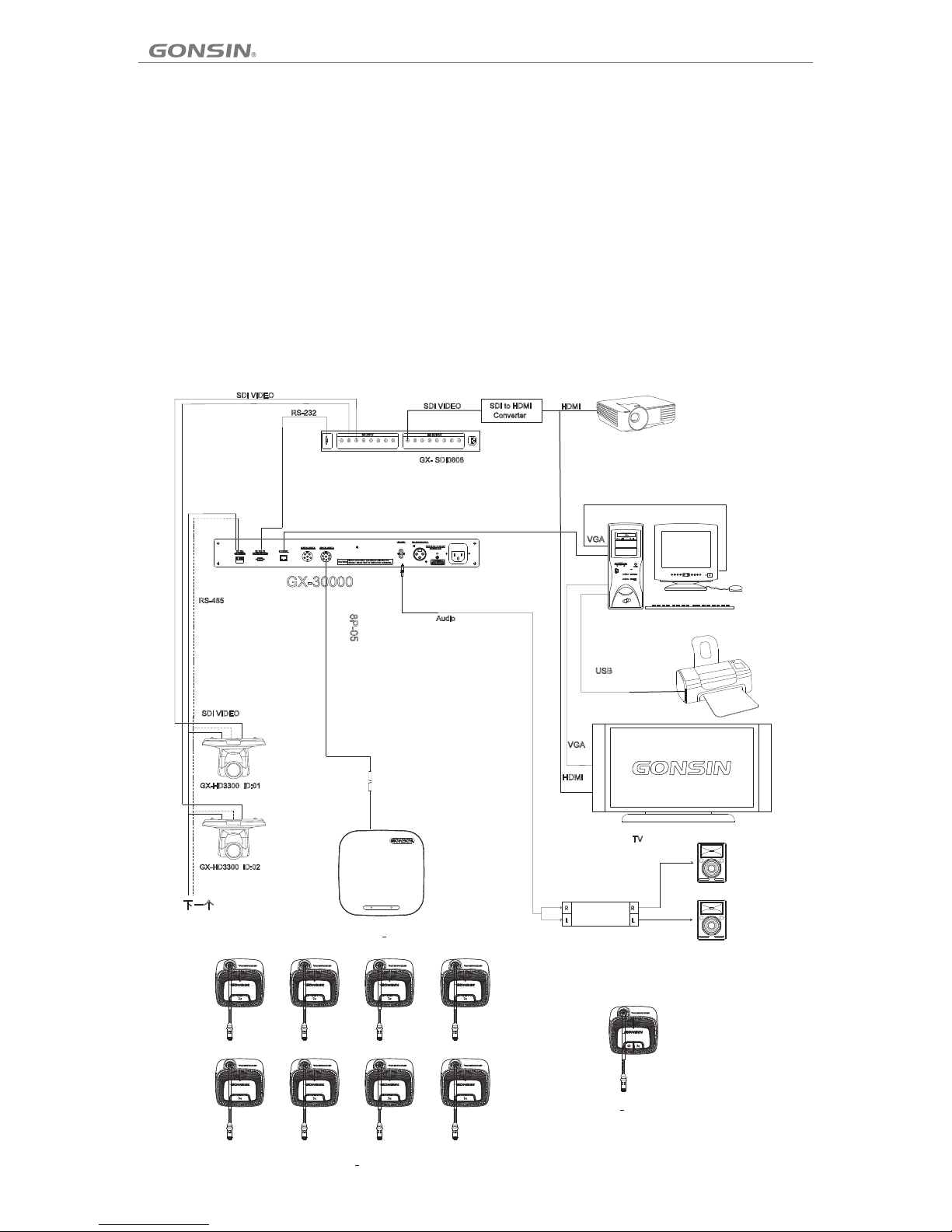
The DCS con gress s ystem is co mposed of t he cong ress serv er, wire le ss cong ress term inals ( for the cha irman and
delegat es), wi reless AP WAP -30, HUB- D45, PC ( optiona l), confe rence m anageme nt soft ware (opt ional), h ighspeed dom e camer as ( optio nal), and a udio de vices and d isplay de vices .
The follo wing fi gure show s the syste m wirin g diagram :
05
-
+
-
+
WAP-30
Power
Amplifier
Projector
DCS-3021DW
DCS-3021CW
8P2-01
Page 7

06
This docu ment is a pplicab le to the fol lowin g product m odels:
Congres s serve r
GONSIN3 0000
Wirel ess AP
WAP -30
Pluggab le Goos eneck Mic rophone S tem
MIC-310 *¢14.5 -Y 310m m Pl uggab le Microp hone St em (Black )
MIC-410 *¢14.5 -Y 410m m Pl uggab le Microp hone St em (Black )
MIC-510 *¢14.5 -Y 510m m Pl uggab le Microp hone St em (Black )
MIC-310 *¢14.5 -Y 310m m Pl uggab le Microp hone St em (Silve r)
MIC-410 *¢14.5 -Y 4 10 mm Plug ga ble Mic rophone S tem (Si lver)
MIC-510 *¢14.5 -Y 510m m Pl uggab le Microp hone St em (Silve r)
Headpho ne
TC-D3 Ste reo Hea dphone
DCS -3021 Cong res s Sys tem
Page 8
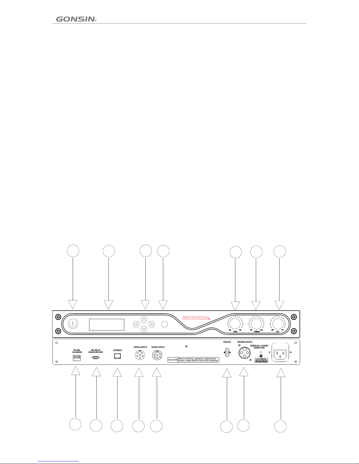
Front sid e Back side :
1. Power sw itch (P OWER); 8. RS-4 85 inte rf ace ( RS-48 5 TO CAMERA) . T his
Note: The serv er tak es a peri od of tim e to st art up.
Before th e se rver is fully s tarted up , do n ot o perate
the congr ess ter minals.
2. Backli ght LCD
Sh ow va ri ou s kin ds o f infor ma tion (s uc h as
operati on mode a nd langu age) and pr ovide a
plurali ty of la nguag es to al low user s to se t the
system. 11.One -chan ne l 6P in terfa ce. Th is inter face is used
3.Opera tion bu ttons: up /down /l eft/r ight arro w butto ns
4. OK butto n
5. Bass adj ustme nt knob (BA SS)
6. Treble ad justm en t knob (T REBLE)
7. Volume kn ob (VOL ) functio n).
2.
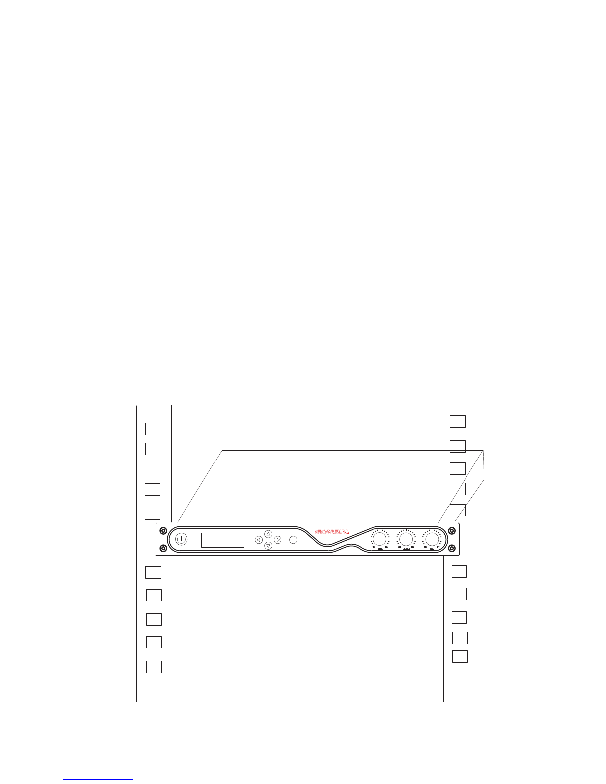
3 Ins
tal
The congre s
brack
ets. Scre w up the bra
sc
rew up it wit h the r
07
Chapter 2 Congress Server
2.1 Overv iew
The DC S co ngress server GON SIN30 000 is the cor e of a co ngres s syst em. It can be conn ected to WAP- 30 or
WAP -30I ( for incr easin g the n umber of liste ning u nits a nd simul taneo us inter preta tion uni ts) as well a s HD ma trix,
mixer, power amp lifier, and PC over corr es pondi ng in terfa ce. The serve r acts as a brid ge to co nnect system
hardwar e a nd control so ftware. It ca n wor k i ndepend ently or be conn ected with a PC to allow op erator to use the
confere nce man ag ement s oftware f or mana gement an d contr ol .
Product m odel:
GONSIN3 0000
Congres s serve r (with dis cussion a nd auto matic cam era tra ck ing fun ctions)
2.2 GONSI N3000 0 Functio ns and Indi cator s
2.2. 1 Bas ic Func tions
1. Us e 2.4 GHz frequenc y hop ping te chnol ogy to autom atica lly detect 2.4GHz RF resource s and use relia ble
frequen cy hopp in g mecha nism to avo id co-c hannel in terfere nce if it i s combine d with so ftware.
2. Use h ig h-efficien cy dig ital aud io com pressio n algo rithm to maxim ize ut ilizati on rat e of wi re less c arriers . Mutu al
interfe rence w ill not be ca used if mul tiple s ystems ar e used in a b ui lding .
3. Suppor t 8*1/8 *8 HD autom atic ca me ra trac king func tion.
4. Suppor t AUTO a nd F IFO spe aking mod es.
5. Suppor t up to fou r speaker s at the sa me t ime (on e chairma n termi na l and thr ee delega te term inals).
6. Suppor t volum e/tune of c ongress t ermin als to be adj usted i n ba tch.
7. Suppor t congr ess termi nals to be sh ut down i n batch, wh ich hel ps e ffe ctively r educe w or kload .
-
+
-
+
OK
1 2
3
4
5
6
7
8
9
10
11
12
13
14
15
2.2. 2 Ind icato rs
Page 9
Front sid e Back side :
1. Power sw itch (P OWER); 8. RS -485 in terfa ce (RS- 485 TO C AMERA). This
interfa ce has two pa irs of connec tion term inals
Note: The serv er tak es a peri od of tim e to st art up.
and i t is used for c onnecti ng t o came ra s t hat
Before th e se rver is fully s tarted up , do n ot o perate
support S ONY\P ELCO-P.
the congr ess ter minals.
9. RS -232 se rial po rt . T his i nt erfac e is used f or
2. Backli ght LCD
connect ing to a PC f or softwa re cont ro l.
Sh ow va ri ou s kin ds o f infor ma tion (s uc h as
10 .Networ k in terfa ce ; this in te rface i s us ed to
operati on mode a nd langu age) and pr ovide a
connect t o a PC or bac kup serve r.
plurali ty of la nguag es to al low user s to se t the
system. 11.One -chan ne l 6P in terfa ce. Th is inter face is used
for c onnecti ng to WA P-30I ( for i ncrea sing th e
3.Opera tion bu ttons: up /down /l eft/r ight arro w butto ns
nu mbe r of l ist en ing u ni ts an d sim ul taneo us
4. OK butto n
interpr etati on units) .
5. Bass adj ustme nt knob (BA SS)
12. One- channel 8P i nterfac e. Th is inte rf ace is used
6. Treble ad justm en t knob (T REBLE)
fo r c on nec ti ng to W AP -30 ( wit h dis cu ssi on
7. Volume kn ob (VOL ) functio n).
13. One gro up of RCA ba la nced au dio outpu t
14. One-c hanne l XL R balan ced audio o utput
15. Power i nterf ace (AC 110-220V 50 Hz)
08
2.
3 Ins
tal
lat
ion
The congre s
s ser ver is 1U
high, and t
herefor e it can be ins
talled in a
19-inch ra ck. It
has two accompa
nied
brack
ets. Scre w up the bra
cket fixe d in tw
o sides of th e co ngres
s serv
er, put the co
ngres
s serv
er int
o the rac
k, then
sc
rew up it wit h the r
ack screw s, as sho
wn in the fol lowin g figure
:
OK
DCS -3021 Cong res s Sys tem
Page 10

2.4.3 Con necti on with Mix er or Amplifie r
The audio output inte rf ace of th e serve r is used to co nnect to a mixer or an ampl ifier for loud speaki ng. Use an
audio cabl e to conne ct th e “ LINE OUT” RCA int erface of the server with co rrespon ding inter face of a mix er or an
amplifi er. Th e fo llowi ng figure s hows th e wiring di agram:
2.4 Conne ction
2.4.1 Con necti on with Con gress Terminal
To connect the congress server with a wireless terminal, use an 8PS-03/05/10/20/40 extension cable to connect the 8P
interface (female connector) of the congress server to a WAP-30 AP, with one male connector of the cable connected to
congress server ,and the other female connector connects the male connector of 8P2-01 male-male connector cable, the
other male connector of 8P2-01 connects to the female connector of WAP-30 AP, as shown in the following figure:
2.4.2 Con necti on with Wir eless AP and Contro l PC
The succ es sful com municat ion betw ee n the congr ess server and a wi reles s termin al must be sup po rted by a
wireles s AP WAP-30 to perfo rm signa l conver sion. Th e cong re ss ser ver is connec ted to a PC over the RJ- 45
connect or. Th e fo llowi ng figure s hows th e wiring di agram:
2.4.4 Con necti on with Cam era
Among th e thre e groups of wir ing from the ca mera (fo r deta ils on ca mera o peratio n, ref er to the camer a operat ion
guide), two gr oups of wiring are us ed for connect ing to th e congre ss ser ver (pow er of the cam era is su pplied
directl y fro m the co nt rol r oom). One group is the HD vi deo w iring, which is impl em ented by connec ting the v ideo
output of the dome camera to the SDIIN PUT of t he HD ma trix over an RGB c onnecto r; where, numbe r 1 –i nput 1;
number 2– input 2. Th e pa noram ic p reset pos ition and the vid eo tracki ng of the chair man termi nal are compl eted by
number 1 ca mera. T he other gr oup is the RS -4 85 wiri ng . Gener ally, us e ne twork cables for commun ication and
select a pa ir of wir es as the “A” a nd “B” of the R S-485 c able. Ref er to the f ollowin g figure:
-
+
-
+
GONSIN30000
8PS-15
RS-485
PC
8
P2-01
Page 11

2.4.3 Con necti on with Mix er or Amplifie r
The audio output inte rf ace of th e serve r is used to co nnect to a mixer or an ampl ifier for loud speaki ng. Use an
audio cabl e to conne ct th e “ LINE OUT” RCA int erface of the server with co rrespon ding inter face of a mix er or an
amplifi er. Th e fo llowi ng figure s hows th e wiring di agram:
1009
2.4.4 Con necti on with Cam era
Among the three groups of wiring from the camera (for details on camera operation, refer to the camera operation guide),
two groups of wiring are used for connecting to the congress server (power of the camera is supplied directly from the control
room). One group is the HD video wiring, which is implemented by connecting the video output of the dome camera to the
SDIINPUT of the HD matrix over an BNC connector; where, number 1–input 1; number 2–input 2. The panoramic preset
position and the video tracking of the chairman terminal are completed by number 1 camera. The other group is the RS-485
wiring. Generally, use network cables for communication and select a pair of wires as the “+” and “-” of the RS-485 cable.
Refer to the following figure:
-
+
-
+
GONSIN30000
RS-485
VIDEO
VIDEO
VIDEO
VIDEO
RS-485
RS-485
RS-485
RS-485
GX-HD3300
GX-HD3300
DCS -3021 Cong res s Sys tem
Power Amp lifie r/Conso le
Page 12

Use 8I+8O HD matrix with the SDIOUTPUT,which is BNC connector. Connect the matrix to a display device (such as
monitor or converter) using an HD video cable. Refer to the following figure:
When connecting the congress server to a SONY EVI-D70/D70 camera, set the COM mode of the camera to RS- 422 and
baud rate to 9600bps; connect RS-485 “+” to RXD IN- and “-” to RXD IN+.
Note: for d etail s on how to set v ideo tr ac king, r efer to the s oftwa re operat ion gui de .
2.4.5 Con necti on with the D ome Contr oller
Make sur e that the GX- KB01 dom e contro ller ’s pro tocol and baud rat e are alr eady pre set (pleas e see dom e
control ler user manu al f or t he settin gs). Use a 2-pin twis ted pair cabl e to con nect 485+ and 485 - of d ome control ler
to 485 + and 485- of centr al con trol unit. Please note that the RS48 5 cont rol ca bl e of do me cam era is alrea dy
connect ed with R S485 cont rol cable o f centr al contro l unit.
The contr ol cabl e of dome con troller c an also b e connect ed to con tr ol cabl e of dome cam era.
2.4.6 Con gress S erver Set ting and Op erati on
The LCD scr een has f ive keys: ▲, ▼, ▶, ◀, a nd
“OK”. After ent ering t he settin g inter face, the c urrent
option is d ispla ye d on a cont rast back groun d. The
leftwar d and rig htward ar row keys ar e used to e nter
or exit a men u.
(1) Curre nt stat us: when th e syste m wo rks nor mally,
the OLED sh ows the n umber of ac tive micr ophon es
and speak ing mod e, a s shown i n the follo wing fi gure:
(
interfa ce, pre ss arrow ke ys to selec t the val ue after
Active MI Cs, and t hen press ▲ o r ▼ to change t he
number of M ICs (1/ 2/3) that c an be act iv ated at t he
same time .
2) Active MI C setti ng: Press O K to ente r th e setti ng
(3) Speakin g mode settin g: on the setti ng
interface , press arrow k eys to select t he value
after Mode an d press ▲ or ▼ to cha nge a
speaking mo de: AUTO or FI FO.
(3) System se tting: on the s etting inte rface, pres s
arrow keys to s elect and ent er the “Syste m”
setting int erface. The interfac e has the follo wing
parameter s for users to se t:
Volume contr ol lock
If volume con trol is locke d, rotating t he volume
knob will not w ork.
If volume con trol is unloc ked, rotati ng the volume
knob will wor k.
Frequency s weep: enter t he "Frequen cy sweep"
interface a nd select "Yes" to co nd uct frequen cy
sweep. Th e system will s can and selec t five
optimal fre quencies fo r the system to u se. If you
select "No" , the system go es back to the
preceding m enu.
Batch shu tdown : Enter the " Batch s hu tdown "
interfa ce and se lect "Yes". The system w ill shu t down
all congr ess ter mi nals; i f you selec t "No", t he system
goes back t o the pre ceding me nu.
-
+
-
+
INTERPRETER UNIT
AUDIO IN
-
+
-
+
+-+-
+-+-
GONSIN30000
1
2
2
Page 13

1211
(3) Speakin g mode settin g: on the setti ng
interface , press arrow k eys to select t he value
after Mode an d press ▲ or ▼ to cha nge a
speaking mo de: AUTO or FI FO.
4 HostID: enter the "HostID" interface to set the host ID
of the system. The default host ID is 00000000.
(4) System setting: on the setting interface, press
arrow keys to s elect and ent er the “Syste m”
setting int erface. The i nterface ha s the followi ng
parameter s for users to se t:
Volume contr ol lock
If volume con trol is locke d, rotating t he volume
knob will not w ork.
If volume con trol is unloc ked, rotati ng the volume
knob will wor k.
Functio nal des criptio n: host ID is a c ode use d within
a system fo r inter nal commu nicatio n. Comm unicati on
can be succ essfu l on ly when t he host ID of t he
system is c onsis tent with t hat of a co ng ress te rminal.
Within a bu ildin g, set different h ost IDs f or multip le
wireles s congr es s syste ms to avoid m utual
interfe rence .
2 Frequency s weep: enter t he "Frequen cy sweep"
interface a nd select "Yes" to co nd uct frequen cy
5 Frequency point: enter the "RF PARM" interface. The
current RFs are shown. Select "SET" to rearrange the five
optimal frequencies; select
"FIX" to re store t o default f reque nc ies. Se lect "OK" t o
return to p reced ing menu.
sweep. Th e system will s can and selec t five
optimal fre quencies fo r the system to u se. If you
select "No" , the system go es back to the
preceding m enu.
3 Unified shutdown: Enter the "Shutdown Unit" interface
and select "Yes". The system will shut down all congress
terminals; if you select "No", the system goes back to the
preceding menu.(Note:when using the microphone with built.
in speaker, the microphone will automatically correspond to
the host frequency after turn on the microphone power,
which means the microphone can be used after scaning the
frequency.)
DCS -3021 Cong res s Sys tem
1
Page 14

1、Battery c apaci ty detect ion
2、Low-voltage alarm and automatic shutdown
3、Hold and press the MIC button on the MIC base to turn on/off the terminal
4、RUN indic ator
5、Attenda nce reg istrati on by butto n press ing or pros thesi s re gistr ation
6、Speakin g mode: A UTO or FI FO; hear a sp eaker v ia the head phone o r bu ilt-i n loudspe aker; v olume is ad justabl e
7、Automat ic vide o trackin g and panor amic pr eset posi tion; i n su pport o f SD and HD vid eo trac king
8、Micro USB i nterf ace for cha rging; li thium b attery is r emova ble for bat ch chargi ng
13
Front sid e:
5、3.5mm jac k。Headp ho ne outp ut interf ace wit h a
3.5mm jac k
1、Microph one goo se neck
6、3.5mm jac k;Audio o utput int erface wi th a 3.5m m
2、Priorit y key (re d)
jack
7、Volume kno b
Bottom:
Press this key to close all active delegate terminals.
This key is available for the chairman terminal only.
9. termin al numb er settin g: Like the d ial-u p setting , the
3、MIC ON/OF F key
defaut is d ialin g up, namel y 0000000 0.
8、Indicat or Ligh t; it blink s when th e co ngres s termina l
Functio n descr iption: h ost ID is a cod e used wi thin a
system fo r inter nal commu nicatio n. Comm unicati on
can be succ essfu l on ly when t he host ID of t he
system is c onsis tent with t hat of a co ng ress te rminal.
is matching with the congress server, it keeps lights on
when the congress terminal matches with the congress
server successfully. It lights green with sufficient
power, otherwise it would light red.
Within a bu ildin g, set different h ost IDs f or multip le
Left side :
wireles s congr es s syste ms to avoid m utual
4、Micro USB i nterf ace for cha rging; th e lithi um
interfe rence .
batteri es can be r emoved an d charged i n batch .
Chapter 3 Compositions of the Wireless Conference System
3.1 Funct ions an d Indicat ors of the Wireles s Congres s Term inal
3.1.1 Ove rview
The congr ess ter minal is es sential f or a conf erence pa rtici pa nt and it c onnects w ith a con gress ser ver via t he
wireles s AP. Functi ons ava ilable to p artic ip ants va ry with the t ype of a co nferenc e unit, i nc ludin g listeni ng,
speakin g, and re qu estin g to speak.
Product m odels :
DCS-302 1C-W Ch airman te rminal wi th basi c discuss ion
DCS-302 1D-W De legate te rminal wi th basi c discuss ion
3.1.2 Bas ic Func tions
3.1.3 Bas ic Func tions
3.2 Funct ions an d Indicat ors of Wi reless AP
The wirel ess AP can t ransm it signal a nd is the t ransit de vice betw een the G ONSIN30 000 ser ve r and DSC -
3021con gress t er minal s. The de vice ut il izes th e advance d selec ting-ho pping tec hnolo gy. Th e wireles s AP has
super-s trong e mi ssivi ty and anti -inte rferenc e capacit y. It ca n transmi t at all di rection s and is immu ne to any
obstacl e.
Notice: o ne cong ress serv er can be con necte d with one wi reles s AP. At the sa me time . The sys tem can con necte d
with WAP-30I w irele ss simult aneou s in terpr etation AP in ord er t o reali ze the simu ltane ous inter pretati on func tion.
The syste m is reco mmended t o use in the me dium or s mall conf erenc e ro om.
Product m odel:
WAP -30
3.2.1 Bas ic Func tions
1、RUN indic ator
2、Powered b y the con gr ess ser ver
3、Wal l mountin g, brac ket suppo rting , an d ceili ng mounti ng
3.2.2 Ind icato rs
1.Signa l indic ator (whe n a microph one is co nnected t o the wir el ess acc ess point , this in dicator w ill flash )
2.6P so cket, f or connec ting with WA P- 30I (fo r adding li steni ng and simu ltaneou s inter pretati on func tions)
3.8P so cket, f or connec ting with WA P- 30( dis cussion f uncti on only)
Page 15

3.2 Funct ions an d Indicat ors of Wi reless AP
The wireless AP can transmit signal and is the transit device between the GONSIN30000 server and DSC3021congress terminals. The device utilizes the advanced selecting-hopping technology. The wireless AP has superstrong emissivity and anti-interference capacity.
Notice: one congress server can be connected with one wireless AP. The system is recommended to use in the medium or
small conference room.
14
Product m odel:
WAP -30
3.2.1 Bas ic Func tions
1、RUN indic ator
2、Powered b y the con gr ess ser ver
3、Wal l mountin g, brac ket suppo rting , an d ceili ng mounti ng
3.2.2 Ind icato rs
1.Signa l indic ator (whe n a microph one is co nnected t o the wir el ess acc ess point , this in dicator w ill flash )
2.6P so cket, f or connec ting with WA P- 30I (fo r adding li steni ng and simu ltaneou s inter pretati on func tions)
3.8P so cket, f or connec ting with WA P- 30( dis cussion f uncti on only)
(Lateral )
DCS -3021 Cong res s Sys tem
Buttom
Front
Back
2
3
1
Page 16

3.2.3 WAP- 30
3.2.3.1 WAP-30 Wireless AP Installation
Wireless transmission is at all directions and cannot be affected by visible rays. So this wireless AP could be used
outdoors. The longest connection distance between the wireless access point and the server can reach 30m. The best way
is to wall hung 2.5m above ground. For detailed installing requirements, please refer to chapter 4 wireless network design.
Notice: It should not have any metal within 2 meter of the installation site, otherwise, the signal transmission would
weaken to some extent
15
3.2.3.2 WAP-30 Wireless AP Installation
3.3 Funct ions an d Indicat ors of Char ging Ca se
The charg ing cas e ca n charg e 16 batter ies at th e same time . It is pow er ed by the u niversa l power s upply and
automat icall y matched b y the volta ge of the c ity power. E ach cha rg ing gri d has a charg ing ind icator li ght. Th e
chargin g circu it c an auto matical ly dete ct the batt ery and c on trol th e chargin g proce ss.
Notice: C HG-16 c harging c ase can cha rge the D SC-3021 c onferen ce term inal. Don ’t use it t o charge ot her types o f
confere nce ter minals.
Product m odel: C HG-16
3.3.1 Bas ic Func tions
1. Smart ma nagem ent of batt eries : en sure se curity an d relia bi lity of c harging p roces s, manage b atter y ca pacit y
and charg ing cur re nt, ext end servi ce life
2. Red/gr een LED i ndicato r to indica te char ging different s tates
3. Chargi ng is imp le mente d by an indep enden t module wi th batter y capac ity detec tion fu nction. W hen no ba tt ery is
inserte d, the ch arging mo dule does n ot work .
4.
Up to 16 batteries can be charged at the same time; charging duration: 3.5h
1、Battery g rid
2、LED indic ator (r ed indica tes "bein g charg ing"; gre en indica tes "ch arging co mplet ed ")
3、Power int erfac e(AC 110 -220v 50H z)
4、 Power swi tch(p ower)
3.4 Conne ction o f Congres s Termin al
To connect th e congr es s serve r with wire less te rminals , use an 8PS- 03/05 /10/20/ 40 exte nsion cab le to conne ct the
8P inte rface ( fe male co nnector ) of the se rver to a WAP-30 AP, with one ma le conn ector of th e cable con necte d to
the congr ess ser ver and the o ther male c onnec tor to the AP. Theore tical ly, the ma ximum dis tance b etween th e AP
and a congr ess ter mi nal is 30 m.
Refer to th e follo wing figu re:
3.3.2 Ind icato rs
( rack moun ting ) (ceilin g mount ed o r wall- mounted )
Page 17

1、Battery g rid
2、LED indic ator (r ed indica tes "bein g charg ing"; gre en indica tes "ch arging co mplet ed ")
3、Power int erfac e(AC 110 -220v 50H z)
4、 Power swi tch(p ower)
3.4 Conne ction o f Congres s Termin al
To connect the congress server with wireless terminals, use an 8PS-03/05/10/20/40 extension cable to connect the
8P interface (female connector) of the server to a WAP-30 AP, with one male connector of the cable connected to the
congress server and the other female connector connects the male connector of 8P2-01 male-male connector cable, the
other male connector of 8P2-01 connects to the female connector of WAP-30 AP. Theoretically, the maximum distance
between the AP and a congress terminal is 30m.
Refer to th e follo wing figu re:
3.3.2 Ind icato rs
16
DCS -3021 Cong res s Sys tem
Connect t he next a p
Page 18

17
Chapter 4 Wireless Network Design
4.1 Intro ducti on
GONSIN3 0000 sy stem is com posed of th ree par ts: GONSI N3000 0 server, WAP-3 0 wirel es s AP, and DC S-3021
congres s termi na l.
This chap ter des cribes ho w to design a w irele ss networ k.
4.2 Contr ol Rule s
Control r ule 1: co nt rol cap ability
GONSIN3 0000 se rver can co ntrol up to 5 00 devi ces withi n a wirel es s netwo rk.
Control r ule 2: co ve rage ra nge
In order fo r the wir eless par ts to opera te bett er, all wire less co ngress te rminals m ust be wi thin the co verag e ra nge
of the wire less AP. Theore tically, the maxi mum cov erage ran ge for the AP is 30m× 30 m. Duri ng use, det ermin e the
actual co verag e ra nge of th e AP.
Control r ule 3: fr eq uency
This wire less ne twork mus t work with in a freq uency ban d that is d iffer ent from th e worki ng freque ncy of adja cent
PC networ k. Refe r to Sectio n 1.3.
4.3 Frequ ency Ba nd
4.3.1 Spe cific ations
This wire less ne twork is ba sed on 2.4G Hz wire less comm unicati on tech nology, so all de vi ces wor k within th e
frequen cy band 2 .4000~2 .4835 GHz .
4.3.2 Wireless P C Network
The wirel ess PC ne twork is ba sed on 2.4G Hz wire less comm unica ti on tech nology as w ell and t here are 13
channel s avail ab le on the P C network . Refer t o Figure 1. 2.
4.3.3 Car rier
In GONSIN 30000 s ystem, th e frequ en cy band 2 .4GHz is di vided i nto 85 chan nels; whe re, cha nnel ( 0 )and
channel s 80~84 a re r eserv ed for comm unica tion of fix ed purpos e. Chan nels 1~79 a re switch able. R efer to Fig ure
1.3.
4.3.4 Int erfer ence
DCS3021 s ystem w il l cause i nterfer ence to t he wirele ss netw or k of PC. Ma ke sure the w irele ss carrie r of the
DCS3021 s ystem d oe s not ove rlap with t he WLAN c hannel.
4.3.5 Exa mple
Refer to Fi gure 1. 4. In this ex ample , th e WLAN wo rks on chan nel 3 whi ch o verla ps with the w irele ss carrie rs 10~35
of GONSIN 30000 . There fore, it is a dvisa ble to use fr equen cy o ther th an carrie rs 10~3 5 in o rder to e nsure
communi catio ns e ffe ct.
Use speci al meas ur ing ins trument s to meas ure the act ual wirel ess env ironmen t or use th ir d-par ty measur ing APP
for evalu ation .
Notes:
Though th is syst em can work a t any fre qu ency, make sure t o abide b y sp ecifi c frequen cy cont rol rules o f the
country y ou loca te.
4.4 Insta llati on Rules
As a wirele ss comm unicati on device , the DCS 3021 shou ld be insta lled in a ccordan ce with r eq uirem ents of
wireles s commu ni catio n product s. Remo ve any obst acle set be tween t he wirele ss comm unicati on device s
(commun icati on r ange wi ll be narro wed by ob stacles ) and remov e any met al around ( wireles s signa l is easily
interfe red by me tals, esp ecially a lumin um). Th e wireles s devic es shall be k ept as leas t 1~2m aw ay from ele ctron ic
product s (elec tronic pr oducts su ch as sta rter, air co nditi oner, micr owave sto ve, and TV set wil l emit ra di o wave
which wil l inter fere with w ireless s ignal ).
The degre e of impa ct on radio s ignals va ries wi th the different k inds of m aterial s:
Minor imp act – gla ss, wood, g ypsum, as besto
Major imp act – wat er, brick, s tone
Complet ely blo ck – marble , cement, c oncre te, metal
The follo wing in structi ons shoul d be foll owed when y ou are in st allin g the wirel ess AP WAP- 30 .
4.4.1 Ins talla tion Heig ht
WAP -30 must be i nstal led at 2.5m h eight a t least to av oid human b ody fro m blockin g communi catio n between t he
WAP -30 and DCS -3021 .
4.4.2 Ins talla tion Dist ance
The commu nicat ion dista nce betwe en WA P-30 an d DCS-302 1 shoul d be a s close a s possibl e and wit hin 30m.
4.4.3 Ins talla tion Envi ronment
Do not set an y metal o r electro nic produ ct that w ill produ ce radi o wa ve with in 2m range o f the WAP-30 .
Figure 1. 2 WLAN ch annel
4.3 Funct ion and I ndicati on of Wir eless Con ference Termi na l and Wir eless C onverte r
Page 19

4.4 Insta llati on Rules
As a wirele ss comm unicati on device , the DCS 3021 shou ld be insta lled in a ccordan ce with r eq uirem ents of
wireles s commu ni catio n product s. Remo ve any obst acle set be tween t he wirele ss comm unicati on device s
(commun icati on r ange wi ll be narro wed by ob stacles ) and remov e any met al around ( wireles s signa l is easily
interfe red by me tals, esp ecially a lumin um). Th e wireles s devic es shall be k ept as leas t 1~2m aw ay from ele ctron ic
product s (elec tronic pr oducts su ch as sta rter, air co nditi oner, micr owave sto ve, and TV set wil l emit ra di o wave
which wil l inter fere with w ireless s ignal ).
The degre e of impa ct on radio s ignals va ries wi th the different k inds of m aterial s:
Minor imp act – gla ss, wood, g ypsum, as besto
Major imp act – wat er, brick, s tone
Complet ely blo ck – marble , cement, c oncre te, metal
The follo wing in structi ons shoul d be foll owed when y ou are in st allin g the wirel ess AP WAP- 30 .
4.4.1 Ins talla tion Heig ht
WAP -30 must be i nstal led at 2.5m h eight a t least to av oid human b ody fro m blockin g communi catio n between t he
WAP -30 and DCS -3021 .
4.4.2 Ins talla tion Dist ance
The commu nicat ion dista nce betwe en WA P-30 an d DCS-302 1 shoul d be a s close a s possibl e and wit hin 30m.
4.4.3 Ins talla tion Envi ronment
Do not set an y metal o r electro nic produ ct that w ill produ ce radi o wa ve with in 2m range o f the WAP-30 .
Figure 1. 4 Signa l interfe rence exa mple
Figure 1. 3 Wirel ess chann el of the GON SIN30 000 syste m
18
4.3 Funct ion and I ndicati on of Wir eless Con ference Termi na l and Wir eless C onverte r
DCS -3021 Cong res s Sys tem
Page 20

4.4.4
Multi-system DCS3021 working in the same building (Several conference system)
Wireless DCS3021 have related restrictions if multi-system working in the same building.
The indoor environment is complicated due to the wall material, thickness, e.g wood wall, cement wall, glass
wall, metal wall will affect audio transmission in different way. In order to ensure best equipment performance,
please refer to below principles to set.
For example, in the same building, we have 5 rooms: A,B,C,D,E
Room A: 2nd floor
Room B: 2nd floor, not far away from Room A
Room C: 3rd floor, above Room A
Room D: 2nd floor, far away from Room A
Room E: 4th floor, at least 2 flooring apart from room A
Situation 1: Room A/B/C on the same floor or neighboring floor, because they are very near each other,
RF PARM, Host ID and broadcast channel shall be DIFFERENT
Room A : RF PARM:FIX 1, Host ID: 001, broadcast channel: 1
Room B : RF PARM:FIX 2, Host ID: 002, broadcast channel: 2
Room C: RF PARM:FIX 3, Host ID: 003, broadcast channel: 3
Situation 2: Room A/D on same floor and not neighboring rooms, if meet below condition, the RF
PARM can be same, Host ID and broadcast channel still are DIFFERENT
Condition shall satisfy below all:
1, The walls are thick cement walls;
2, The distance between WAPs is no less than 30meters;
3, WAP in 2 rooms are back-to back installing, which means, the front panels are not face to face
installing.
The setting
Room A: RF PARM:FIX 1, Host ID: 001, broadcast channel: 1
Room D: RF PARM:FIX 1, Host ID: 004, broadcast channel: 4
1
9
Page 21

4.4.5 DCS3021 working with other wifi devices
DCS3021 system has 3 channel:
channel 1, channel 2, channel 3,
Channel1 corresponding to WLAN1
Channel2 corresponding to WLAN6
Channel3 corresponding to WLAN11
Although there are 14 channel in wifi devices, but the unrepeated channels between DCS3021 and other wifi
devices are only 3 channel, WLAN 1/6/11. It’s suggested set the channel on 1/6/11, which will reduce
interferences.
1, If on the same flooring or neighboring flooring:
only 3 set DCS3021 system can work at the same time, on different Host ID;
Because there are only channel 1, channel 2, channel 3 for each system, cannot be repeated used; Besides,
the HOST ID and broadcast channel shall be different setting.
2, If there are other extra 2.4GHz wifi devices working together:
On the same flooring or neighboring flooring, only 2 set DCS3021 can work at the same time. Their RF
PARM can be as below: Channel 1/Fix2/Fix3, or Fix 1/Channel 6/Fix3, or Fix1/Fix2/Channel 11. the HOST ID
and broadcast channel of DCS3021 shall be different. The other 2.4GHz wifi devices can reserve one
channel to work in this same channel. Network management is necessary.
3, If the rooms are not same flooring or neighboring flooring (at least 2 flooring apart):
the RF PARM can be repeated used. Due to the signal is not overlapping, Host ID and broadcast channel
can be repeated used.
4.4.6 Auto and manual RF scan
DCS3021 shall work on clean frequency points to ensure stable sound. If continuously interference, the
sound will interrupt severely. After WAP installing, it’s suggested to use RF scan software to check wifi
environment.
If the wifi environment is low interference, the software will show green column, which means low
interference, we can use auto RF scan;
If the wifi environment is high interference, the software will show many red columns, which means, wifi
management is necessary, at least reserve one clean channel for DCS-3021 working; in this case, manual
setting channel 1-3 channel working is necessary.
19
Page 22

20
Chapter 5 Accessories
5.1. 1 Wi reless AP Cable 8P2-1.5
Item Descrip tion
Color Black
Type 8P2
Connect or Ma le connec tor x 2
Length 1.5m
5.1. 2 8PS- 03 \05\10\15\20\40 Exte ns ion Cable
Item
Color Black
Type 8PS
Connect or Male c onnecto r x 1,
female co nnect or x 1
Length 5 ty pes, na mely 3m, 5m , 10m,1 5m ,
20m
Descrip tion
5.1. 3 UT P-Five Category Cable ( op tional)
Item De scrip ti on
Length >3 m
Network C able UTP
Conduct or 26 AWG C opper-c lad alu mi num
conduct or
Connect or Type Rj 45
Maximum p roces si ng capa city
Communi catio n di stanc e
Audio fre quenc y respons e
Rated pow er
Harmoni c disto rtion
Signal to n oise ra tio
Maximum a udio ou tp ut
Main powe r
Install ation
Dimensi ons (L × W × H)
Weigh t
Operati ng temp erature
Storage t emper ature
Interfa ce for vi deo track ing
Speakin g mode
Qty. of ac tive mi crophon es
Protoco l for cam era contr ol
Interfa ces
Produ ct Name
Item
6.1 Co ng ress Server GONSIN300 00
Page 23

Maximum p roces si ng capa city
Communi catio n di stanc e
Audio fre quenc y respons e
Rated pow er
Harmoni c disto rtion
Signal to n oise ra tio
Maximum a udio ou tp ut
Main powe r
Install ation
Dimensi ons (L × W × H)
Weigh t
Operati ng temp erature
Storage t emper ature
Interfa ce for vi deo track ing
Speakin g mode
Qty. of ac tive mi crophon es
Protoco l for cam era contr ol
Interfa ces
500 (sets )
30m
30Hz-16KH z
72W
(THD) < 0.5%
≥7 5dB (signal to noise ratio based on A weight) LINE
OUT:+20dBu;
AV110/220V±10% 50~60Hz
19inch standard rack
1U rack (340mm×420mm×45mm)
4KG
0~45°C
-20~50°C
RS-485
AUTO, FIFO
1/2/3+1
PELCO-P 9600/VISCA
1. RS-232 × 1 ( conne cted to a cam era for v id eo trac king);
2. RJ-45 (c onnec ted to a PC);
3. RS-485 b us (for c amera con trol);
4. 8P soc ket (co nn ected t o a wireles s AP);
5. One-ch annel b al anced a udio outp ut (XLR c onnecto r);
6. Two-c hannel no n-bal anced aud io output ( RCA co nnect or);
21
Produ ct Name
Item
GONSIN30000 Congress Server
Parameter
Chapter 6 Technical Indicators
6.1 Co ng ress Server GONSIN300 00
DCS -3021 Cong res s Sys tem
Page 24

6.2 Co ng ress Terminal 3021 6.3 Ch ar ging Case CHG-16
COM mode
Audio fre quenc y respons e
Signal to n oise ra tio
Sensiti vity
Operati ng volt age
Battery c apaci ty
Battery l astin g time
Dimensi ons (L × W × H)
Goosene ck leng th
Weigh t
Headpho ne jack
Speakin g mode
Qty. of ac tive mi crophon es
Attenda nce reg istrati on
Operati ng temp erature
Storage t emper ature
Sound pic kup dis ta nce
Built-i n louds pe aker
Produ ct N ame
Item
2.4GHz fr equen cy hoppin g
30Hz-16KH z
≥7 5dB
-46dB±1 dB
3.7V
2600mAH l ithiu m- ion bat tery
DCS-302 1C-W wi re less ch airman te rmina l with basi c
discuss ion
DCS-302 1D-W wi re less de legate te rmina l with basi c
discuss ion
Paramet er
22
≥20h (spea king st ate)
141mm×1 61mm× 53 mm
310mm
0.5 kg
3.5MMja ck ster eo
AUTO, F IFO
1/2/3+1
Button pr essin g
0~45°C
-20~50° C
10~40cm
4Ω3W
Power sou rce
Highest c hargi ng v oltag e
Power
Chargin g durat io n
Weigh t
Dimensi ons
Operati ng temp erature
Storage t emper ature
Produ ct N ame
Item
Page 25

Power sou rce
Highest c hargi ng v oltag e
Power
Chargin g durat io n
Weigh t
Dimensi ons
Operati ng temp erature
Storage t emper ature
Produ ct N ame
Item
Chargin g case
Paramet er
AC100~2 40V, 50~60H z
4.2V
106W
3.5h
6.7 kg (net w eight ) / 7.4 kg (ful ly load ed )
490mm×3 20mm× 67 .5mm
0~45°C
-20~50° C
DCS -3021 Cong res s Sys tem
23
Page 26

1. The co ngress se rver do es not resp ond aft er it is star ted up an d co rresp onding in dicat or i s on.
A: The se rver is a PC an d it shou ld perfor m a self- check bef ore activ ating t he entire s ystem . The ser ver takes m ore
than 1 minu te to sta rt up.
2. The co ngress te rmina l cannot be s tarte d up or an erro r occurs du ring st artup.
A: The se rver does n ot dete ct the cong ress te rminal.
① Start the s erver. M ake sure th e server ha s been co mpletel y start ed u p befor e switchi ng on the c ongress
termina l.
② Check whe ther th e termina l has been st arted u p.
③ Check whe ther th e wireles s AP is prop erly co nn ected t o the serve r.
④ If the prob lem per sists, co ntact tec hnici ans.
3. The do me camera c annot b e control led.
A:
①Check whe ther th e "+" and "–" o f the RS-48 5 cable i s reverse ly connec ted and w hether th e coppe r core of the
binding p ost is in se rted in to the RS-4 84 inte rface of th e centr al c ontro l unit and lo cked.
②Check the I D and pro tocol set tings of th e dome ca mera. The centra l contr ol unit sup ports P ELCO-P9 600 camer a.
4.The pow er butt on of the mic rophone k eeps bl inking?
With the sa me ID ser ver, ① when se rver swee ps freq uency and f inish ed , the lig ht of power b utton o f the
microph one wou ld k eep bli nking and i ndica ti ng the cu rrent con gress t erminal i s match in g with th e server. As th e
match is fi nishe d, the ligh t stop blin king, t he congre ss term in al woul d operate n ormal ly ; ①when th e server is
writing n umber o f congres s termina ls. The l ight of p ower butt on of the m icropho ne woul d ke ep blin king. Pre ss the
microph one pow er b utton , the light s tops bl inking, a ll cong re ss term inals wou ld fini sh ed the nu mber writ ing.
24
Chapter 7 Environment and Maintenance
7.1 Syste m Requi rements
A proper wor king en vi ronme nt and prop er main tenance m ethod can h elp ext end servi ce life of th e devic es. Befor e
operati on or mai ntenanc e, please r ead thi s chapter c arefu lly.
7.2 Publi c Envir onment Re quireme nts
Wires mus t be inst alled in in visible p laces a nd device s urface mu st be kep t clean. Wh en spea ki ng into a
microph one, ke ep a d istan ce. The m icrop ho nes are h ighly dir ectio na l, so poi nt them to a sp ecifi ed direct ion whe n
speakin g into th em. Do not us e alcohol o r ammon ia to clean d evices. U se soft c loth and cl eanin g agent (e. g.
Pledge cl eanse r) t o clean t he device s.
7.2.1 Technical R equir ements on P ublic Env ironm ent
1. Keep ind oor env ir onmen t hygieni c.
2. Keep ind oor env ir onmen t airy.
3. Keep pro per lig ht and ensu re system o perat ion is not affecte d by ligh t.
4. Do not pla ce irre levant ar ticles on d evice s to avoid bl ocking ve ntila tion or hea t dissi pa tion; o therwis e, the
product p oses a ri sk of fire or e lectric s hock.
5. Do not set t he devi ces to mois t place or ex pose th em to rain; o therw ise, the pr oduct pos es a risk o f fire or oth er
damage.
6. Do not dis mantl e the housi ng of the con gress t erminal s; othe rw ise, th e product p oses a ri sk of elect ric sho ck . To
maintai n the dev ices, con tact GONS IN afte r-sales s ervic e center.
7. This p roduct is a pplic able to ind oor use o nl y; make s ure not to ex pose it t o direct su nlight. I f cable c oating is
damaged , the pro du ct pose s a risk of ele ctric s hock or fir e.
7.2.2 Sys tem Ope ration Re quireme nts
GONSIN co nfere nce manag ement sof tware m ust be supp orted b y a PC in order t o run. Gene rally, the syst em
operato r is loca ted in an ind ependen t room wh ich shoul d reach the s tanda rds of an int erpre te r booth . The roo m
should be c onfig ur ed with s imultan eous in terpret ation d ev ices (m icropho nes) to c on nect to a PA system so t hat the
operato r can rem ind parti cipants o f relat ed operat ion, fo r ex ample , voting st arts or r egistra tion st arts. An audio
device sh ould be i ns talle d in the room a s well to a llow the op erator to c learl y hear the si te and un de rstan d site
situati on.
Notes:
1. Keep goo d venti lation co ndition s. Rese rve holes o n the upp er p art of th e devices a nd plac e the devic es on a flat
and stabl e floor.
2. If the ope ratio n room will b e left unus ed for a lo ng period o f time, s hu t down th e power sup ply or re move and
store the d evice s in an airy dr y place.
Page 27

Chapter 8 FAQs
1. The co ngress se rver do es not resp ond aft er it is star ted up an d co rresp onding in dicat or i s on.
A: The se rver is a PC an d it shou ld perfor m a self- check bef ore activ ating t he entire s ystem . The ser ver takes m ore
than 1 minu te to sta rt up.
2. The co ngress te rmina l cannot be s tarte d up or an erro r occurs du ring st artup.
A: The se rver does n ot dete ct the cong ress te rminal.
① Start the s erver. M ake sure th e server ha s been co mpletel y start ed u p befor e switchi ng on the c ongress
termina l.
② Check whe ther th e termina l has been st arted u p.
③ Check whe ther th e wireles s AP is prop erly co nn ected t o the serve r.
④ If the prob lem per sists, co ntact tec hnici ans.
3. The do me camera c annot b e control led.
A:
①Check whe ther th e "+" and "–" o f the RS-48 5 cable i s reverse ly connec ted and w hether th e coppe r core of the
binding p ost is in se rted in to the RS-4 84 inte rface of th e centr al c ontro l unit and lo cked.
②Check the I D and pro tocol set tings of th e dome ca mera. The centra l contr ol unit sup ports P ELCO-P9 600 camer a.
4.The pow er butt on of the mic rophone k eeps bl inking?
With the sa me ID ser ver, ① when se rver swee ps freq uency and f inish ed , the lig ht of power b utton o f the
microph one wou ld k eep bli nking and i ndica ti ng the cu rrent con gress t erminal i s match in g with th e server. As th e
match is fi nishe d, the ligh t stop blin king, t he congre ss term in al woul d operate n ormal ly ; ①when th e server is
writing n umber o f congres s termina ls. The l ight of p ower butt on of the m icropho ne woul d ke ep blin king. Pre ss the
microph one pow er b utton , the light s tops bl inking, a ll cong re ss term inals wou ld fini sh ed the nu mber writ ing.
25
DCS -3021 Cong res s Sys tem
Page 28

Appendix:
Copyrig ht stat ement GON SIN Confe rence E quipmen t Co., Ltd.
¤ Witho ut the auth orizati on of GON SIN Confe rence Equ ipmen t Co., Ltd. , reprodu ction a nd transm ission of
this docu ment is f orbidde n.
¤ GONSIN ma kes eve ry effort t o ensure ac curac y and conci seness of t he cont ents in thi s documen t. For
any inacc uracy d ue to print e rror, plea se cont act us, and w e will corr ect it in a t imely man ner.
¤ Due to prod uct upg rade or cha nge of prod uct app earance a nd specif icati on, infor mation in t his
documen t is subj ect to chan ge withou t notic e. GONSIN r eserves t he righ t of final in terpret ation .
¤ Before us e, plea se carefu lly read th is user m anual. Fo r any uncla rity, pl ease vi sit GONSI N website o r
contact o ur tech nicians o r agents.
Thank you f or usin g GONSIN pr oducts!
Websi te: www.go nsin. com
After-s ale Ser vice Tel : 0757-22 382369
Fax: 0757 -22211 036
Postal co de: 528 30 0
Address:
10th Floor, Block 2, Jinyuehongtai Building,
No.4 Chengye Road , Fengxiang Industrial
Park, Shunde,Foshan, Guangdong,
528300, China
26
Page 29

DCS -3021 Cong res s Sys tem
27
Page 30

GONSI N Con ference Eq uip ment Co ., Lt d.
 Loading...