

Gonnheimer Elektronic D122.T User Manual
User's manual
Set-point-
transmitter
D122.T
Edition of standards 2010, Software version 1.2.0

D122.T Manual Page 2
Gönnheimer Elektronic GmbH phone: +49(6321)49919-0, fax: -41 Email: info@goennheimer.de
Table of Contents
1 Operation instruction for Explosion protected device................................................................4
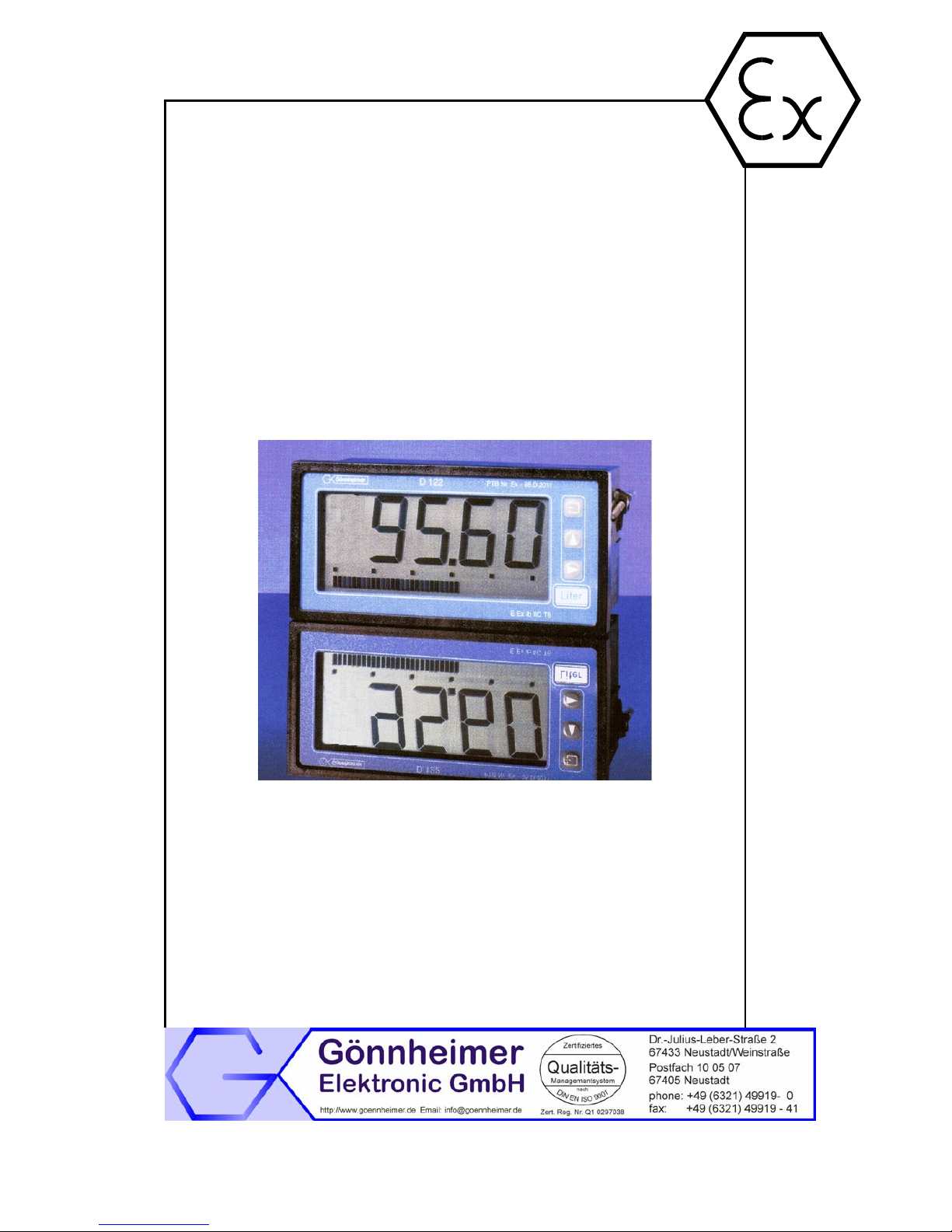
2 Transmitter D122.T..........................................................................................................................5
2.1 Short description........................................................................................................................5
2.2 Features overview .....................................................................................................................5
2.3 Conformity with Standards.........................................................................................................6
3 Installation and Connection...........................................................................................................6
3.1 D122.T with control panel housing ............................................................................................6
3.1.1 Installation control panel housing.......................................................................................6
3.1.2 Connecting D122.T with control panel housing..................................................................6
3.2 Field housing D122.T.................................................................................................................7
3.2.1 Connecting D122.T with field housing................................................................................7
3.3 Initial operation...........................................................................................................................8
3.3.1 Ex works settings – Device reset .......................................................................................8
4 Operation manual............................................................................................................................9
4.1 Front view and push-keys..........................................................................................................9
4.2 Configuration............................................................................................................................10
4.3 Configuration example.............................................................................................................13
5 Flow charts ....................................................................................................................................16
6 Annex .............................................................................................................................................19
6.1 Specifications...........................................................................................................................19
6.2 Type code................................................................................................................................19
6.3 Dimensions..............................................................................................................................20
6.4 Application example: connection plan.....................................................................................21
6.5 Material specification ...............................................................................................................21
6.6 Marking....................................................................................................................................21
6.7 Transport, Storing, Repairs und Disposal................................................................................22
6.8 Failure messages.....................................................................................................................22
6.9 List of Parameters....................................................................................................................22
D122.T Manual Page 3
Gönnheimer Elektronic GmbH phone: +49(6321)49919-0, fax: -41 Email: info@goennheimer.de
The symbols WARNING, CAUTION, NOTE
This symbol warns of a serious hazard. Failure to observe this
warning may result in death or the destruction of property.
This symbol warns of a possible failure. Failure to observe this
caution may result in the total failure of the device or the system
or plant to which it is connected.
This symbol highlights important information.
D122.T Manual Page 4
Gönnheimer Elektronic GmbH phone: +49(6321)49919-0, fax: -41 Email: info@goennheimer.de
1 Operation instruction for Explosion protected device
Application and Standards
This instruction manual applies to explosion-protected control panels of type of protection
types below. This apparatus is only to be used as defined and meets requirements of EN 60
079 particularly EN60 079-14 "electrical apparatus for potentiality explosive atmospheres".
Use this manual in hazardous locations, which are hazardous due to gases and vapours according to the explosion group and temperature class as stipulated on the type label. When
installing and operating the explosion protected distribution and control panels you should observe the respective nationally valid regulations and requirements.
General Instructions
The device has to have a back-up fuse as stipulated. The mains connection must have a sufficient short circuit current to ensure safe breaking of the fuse. To achieve an impeccable and
safety device operation, please take care for adept transportation, storage and mounting, as
well as accurate service and maintenance. Operation of this device should only be implemented by authorised persons and in strict accordance with local safety standards.
The electrical data on the type label and if applicable, the "special conditions" of the test certificate Fehler! Unbekannter Name für Dokument-Eigenschaft.are to be observed.
For outdoor installation it is recommended to protect the explosion protected distribution and
control panel against direct climatic influence, e.g. with a protective roof. The maximum ambient temperature is 40°C, if not stipulated otherwise.
Intrinsically Safe Circuits
Erection instructions in the testing certificates of intrinsically safe apparatus are to be observed. The electrical safety values stipulated on the type label must not be exceeded in the
intrinsically safe circuit. When interconnecting intrinsically safe circuits it is to be tested,
whether a voltage and/or current addition occurs. The intrinsic safety of interconnected circuits
is to be ensured. (EN 60079-14, section 12)
Safety Measures: to read and to comply
Work on electrical installations and apparatus in operation is generally forbidden in
hazardous locations, with the exception of intrinsically safe circuits. In special cases
work can be done on non-intrinsically safe circuits, on the condition that during the
duration of such work no explosive atmosphere exists. Only explosion protected
certified measuring instruments may be used to ensure that the apparatus is voltage-free. Grounding and short-circuiting may only be carried out, if there is no explosion hazard at the grounding or short circuit connection.
Danger of static charge!
Clean only with humid cloth!
Do not open when an explosive dust atmosphere is present!

D122.T 2 Set point transmitter D122.T Page 5
Gönnheimer Elektronic GmbH phone: +49(6321)49919-0, fax: -41 Email: info@goennheimer.de
2 Transmitter D122.T
2.1 Short description
The purpose of the D122.T is to make set-point adjustments, like e.g. temperature, pressure
or revolution, inside the explosion endangered area to e.g. high level control units outside explosion endangered areas, via a 4/20 mA current circuit.
The scale span of the transmitter amounts 2000 digits. An additional power supply is not necessary, because the D122.T is in loop like a transmitter into the circuit of a transmitter power
supply.
The indicated value corresponds with the real measured current in the control circuit - it is not
just a static display. So, the user has control of the transmitted set point. Push and hold the
current control button to indicate the physical current in dimension mA.
The D122.T has a configurable incremental set point- setting. The user sets a new set point
by pressing the arrow buttons to increment or decrement the desired set point. The incremental set point- setting works first with an resolution of 1 digit and furthermore with an adjust
progression – so wide set point- adjustments can be done quickly.
Use an additional D122.A indicator to indicate the actual value of the feedback control system.
Therefore, a hazardous area located simple process visualisation of a feedback control system.
2.2 Features overview
; Ex i- Set-point transmitter D122.T into 4 /20 mA control circuit
• Loop powered - easy use in hazardous area, no additional power supply necessary
• Connecting like common transmitters
; Display
• 41/2-digit 7-Segment display, 2000 digits
• LC-Display 30 mm digit height
• Fast bargraph for trend observation, (41 segments, refresh 4 times per second)
; Housings
• Control panel housing, protection class up to IP 55 (HxWxD) 72x144x80 mm
• Field housing, protection class IP 65 (HxWxD) 133,5x138x64 mm
; Ergonomics
• µ-Processor technology for extensive configuration
• Scaled by keyboard and display, without reference current
• Separately scaleable bargraph (Zoom)
• Incremental set point setting (software version 1.1.0 and later)
• Current control button (not available by incremental set point setting)
• Keeps the configuration after turn off
• Ability to change configuration during operation
• Exchangeable dimension signs
; Service
• Customised calibration
D122.T 2 Set point transmitter D122.T Page 6
Gönnheimer Elektronic GmbH phone: +49(6321)49919-0, fax: -41 Email: info@goennheimer.de
2.3 Conformity with Standards
The explosion proof indicators type D122.T meets requirements of listed standards in the attachment
(Declaration of conformity). They were developed, manufactured and tested in accordance with stateof-the-art engineering practice and ISO9001:2008.
3 Installation and Connection
3.1 D122.T with control panel housing
3.1.1 Installation control panel housing
The D122.T.3 is predicated for installation in a control panel.
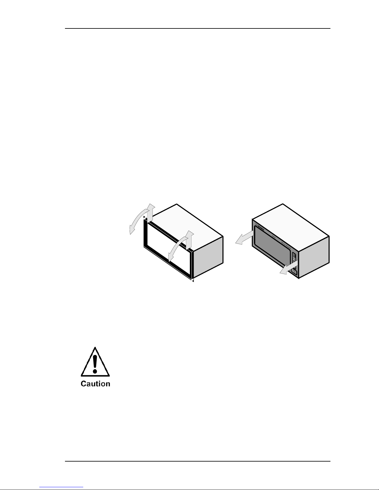
How to insert
the dimension
symbol
Insert the dimension symbol (icon) before mounting. Do this by first
removing the front frame as shown in the figure at left. Now remove
the front panel from the housing as shown in the figure on the right.
Cut the desired dimension symbol out of the set and pull it into its intended place on the right side of the panel. Make sure that the symbol
is facing the front. Replace the front panel and frame.
How to fix the
device in the
control panel
Fix the device into the control panel with the intend cramps.
3.1.2 Connecting D122.T with control panel housing
Connect the indicator only to intrinsically safe
4..20 mA current circuits.
The terminals of the indicators in the control panel housing are
shown in figure Fehler! Verweisquelle konnte nicht gefunden
werden.. The terminals 5,6 and 7,8 are absent by indicators without
alarm monitoring.
D122.T 3 Installation and Connection Page 7
Gönnheimer Elektronic GmbH phone: +49(6321)49919-0, fax: -41 Email: info@goennheimer.de
Please regard the terminal maximum values of the attached EC- type certificate TÜV 99 ATEX 1488 .
Control panel
enclosure
The terminals of the transmitter in the control panel housing are on the
backside.
Terminal Comment
1 + terminal 4 ..20 mA control circuit
Terminals
2 - terminal 4 ..20 mA control circuit
3.2 Field housing D122.T
Choose a solid place to install the transmitter in the field area.
How to insert
the dimension
symbol
First, cut the desired dimension symbol out of the set. Then pull off the
four screws of the cap and remove the cap from the housing.
Now push the prepared dimension symbol into the dimension symbol
slot. Make sure that the symbol is facing the front.
The dimension symbol slot are below the display, on the internal side
of the cap.
Finally replace the cup on the housing.
3.2.1 Connecting D122.T with field housing
Connect the indicator only to intrinsically safe
4..20 mA current circuits.
The terminals of the indicators in the control panel housing are shown
in figure Fehler! Verweisquelle konnte nicht gefunden werden..
The terminals 5,6 and 7,8 are absent by indicators without alarm monitoring.
Please regard the terminal maximum values of the attached EC- type certificate TÜV 99 ATEX 1488 .
Field
housing
The terminals of the transmitter with field housing are inside.
Terminal Comment
1 + Terminal 4..20 mA control circuit
Terminals
2 - Terminal 4..20 mA control circuit
D122.T 3 Installation and Connection Page 8
Gönnheimer Elektronic GmbH phone: +49(6321)49919-0, fax: -41 Email: info@goennheimer.de
3.3 Initial operation
After connecting, a display test (all segments of the display are on)
appears immediately during one second. Thereupon the display
shows the software version of the transmitter.
Default
parameters
The following parameters are active ex works:
Scale (figure and bargraph)
• 4 mA measured current -> 4.00
• 20 mA measured current -> 20.00
Set point
• 4 mA measured current -> 4.00
• Direct set point setting
Code words
• CODE1: 0001
• CODE2: 0002
3.3.1 Ex works settings – Device reset
Press the Enter- and Right-button during the start sequence to
reactivate the default parameters. (Hardware-Reset)
A reset activates also the ex works calibration.
D122.T 4 Operation manual Page 9
Gönnheimer Elektronic GmbH phone: +49(6321)49919-0, fax: -41 Email: info@goennheimer.de
4 Operation manual
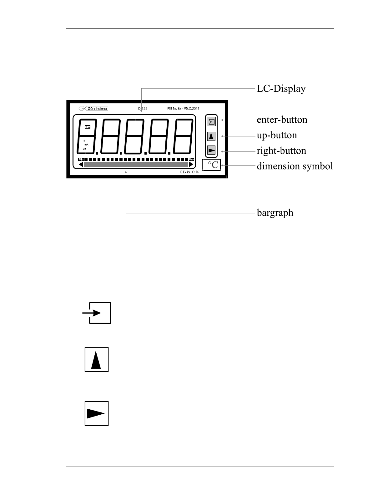
4.1 Front view and push-keys
; Front view
; Keys
On the front side of the transmitter are tree buttons with several function symbols. With these
tree buttons the user can activate each function and enter any parameters for any individual
setting.
Each button is named by its function:
Enter-button
Pressing the enter-button starts the input menu.
In general, the enter-button activates the menu item or accepts the manipulated value of a parameter.
Up-button
Functions of the up-button are:
1. present current value button or
increment set point
2. modification of the selected figure
3. pass menu items
Right-button
Functions of the right-button are:
1. change the state to set point edit menu or
decrement set point
2. select figures
3. pass menu items
D122.T 4 Operation manual Page 10
Gönnheimer Elektronic GmbH phone: +49(6321)49919-0, fax: -41 Email: info@goennheimer.de
4.2 Configuration
It is easy to set the parameters and change the configuration of the transmitter. The inputs
are logical grouped by a menu structure. The flow charts of these menus can be found at
chapter 5.
, Note Flow
charts
SET
The Input-views in the flow diagrams have additional
boxes in their background, because the Input-views may
be changed by pressing any button.
The procedure, to enter a value, is shown in the flow
chart ‘Edit menu’, see Figure 4: Flow chart edit mode
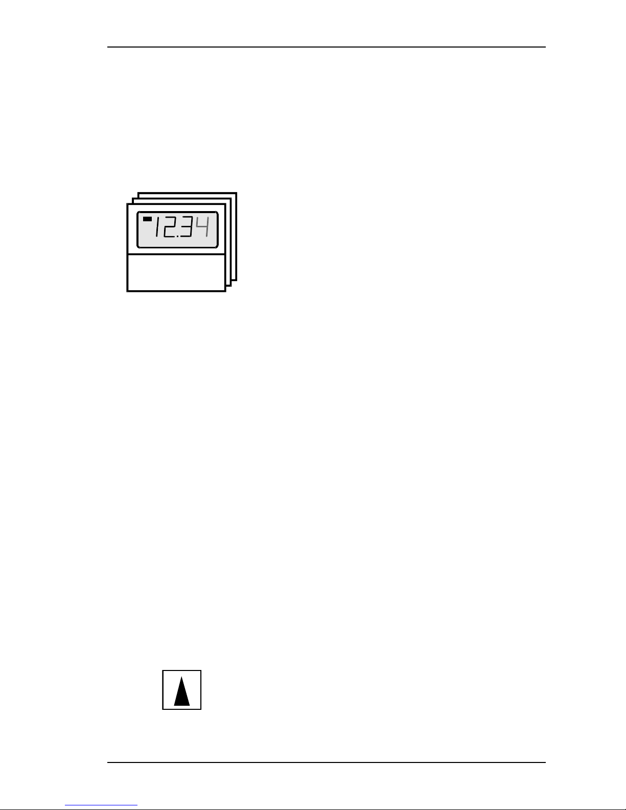
) Normal state
After connecting, the transmitter D122.T starts to initialise its
configuration. The configuration data is stored in an internal
EEPROM due to the previous run. On the first start, the
D122.T transmitter initialises the ex works configuration.
Directly past starting sequence the transmitter begins to
operate. This state is called the ‘normal state’ of the D122.T
and the transmitter is also ready for inputs.
(See also flow diagram in Figure 1)
) Set point
adjusting
It is possible to adjust the set point in two ways:
1. Direct set point setting: the user pushes the right-
button following the enter-button. The D122.T is then in
the set point edit mode and the user can enter the new
set point by editing the figures of the set point.
2. Incremental set point setting: the transmitter is in
normal state. The user pushes the up-button to increment the set point or he pushes the right-button to decrement the set point .
Configure the way of the set point adjustment in the input
menu of the D122.T (as shown below). The direct set point
setting is configured ex works.
, Tip*
If the incremental set point setting is active – then the present current control as well as the direct set point setting is
not available.
) Present-value
control*
Pushing and holding the up-button (present value control
button) the display shows the present measured value.
(See also flow diagram in Figure 1)
D122.T 4 Operation manual Page 11
Gönnheimer Elektronic GmbH phone: +49(6321)49919-0, fax: -41 Email: info@goennheimer.de
) Direct set point
setting*
One touch on the right-button starts the preset menu.
(See also flow diagram in Figure 1: flow chart normal state)
SET
SET
The transmitter screen shows “SET”.
Press the enter-button to see the present preset value.
Press the enter-button a second time, to change the preset
value.
The display switches into the
; Edit mode.
_1234
A blinking segment appears below the sign place. Pressing
the right-button selects the figures and the up-button incre-
ments the selected figure. To accept the new preset value,
press the enter-button.
(See also flow diagram in Figure 4)
; Code protection
CodE 2
Before the menu gets to the edit mode the code 2 must be
entered, to prevent a modification by unauthorised per-
sons. Entering a wrong code word stops the limit view
menu immediately.
The default code 2 is [0002].
The interrogation of code 2 can be switched off by modifying the code 2 to [0000]. For this reason the flow diagram
shows the code interrogation in stroked dots. To change the
code you must enter the input menu, as shown below in this
chapter.
; Parameter
entering
(See also flow diagram in Figure 2)
Back in the normal state of the transmitter we start the
) Input menu
by pressing the enter-button.
CodE 1
The configuration of the transmitter is protected against manipulations by unauthorised persons with the code 1. To join the
input menu enter the code 1 .(Default: 0001).
It’s impossible to switch off the code 1 interrogation.
D122.T 4 Operation manual Page 12
Gönnheimer Elektronic GmbH phone: +49(6321)49919-0, fax: -41 Email: info@goennheimer.de
After entering the right code word the transmitter proposes to join
the
SCAL
Scale menu. The figure on the left hand appears on the display.
To scale the measured current, the bargraph and to set the
decimal point join the scale menu by confirming with the enter-
button.
(See also flow diagram in Figure 3).
Enter the upper scale point correct figured ‘as big as possible’
(the first figures should not be ‘0’)
In this case you get the maximum precision of the transmitter.
SET
Press the right-button to pass the scale menu and select the
second submenu, the preset menu. To join it, press the en-
ter-button.
(See also flow diagram in Figure 4)
roll
This is the menu item to configure the way of the set point
setting.
Start with pressing the enter-button. Now toggle between
[roll n] (= roll – no i.e. direct set point setting) and [roll y] (=
roll – yes, i.e. incremental set point setting) by pressing any
arrow button.
Confirm the desired configuration by pressing the enter-
button.
CodE 1
CodE 2
The next two following items allow to manipulate the words
for code 1 and code 2. The enter-button confirms the input
and the corresponding code appears in edit mode.
Remember that the code word [0000] will switch off the code
2.
CAL
Finally it’s possible to calibrate the transmitter with the following submenu called calibration menu. Regard, the
transmitter is already calibrated ex-works.
In general, a further calibration is not necessary and
only experienced persons are allowed to calibrate it.
End
Now we reach the end of the input menu. Confirm all settings with the enter-button. The transmitter switches back to
normal state.
If you want to repeat the input menu, press the right-button.
 Loading...