

Gonnheimer Elektronic D122.A Series, D122.A.6 Series, D122.A.5 Series, D122.A.0 Series, D122.A.3 Series User Manual
User's manual
Digital Indicator
D122.A
Edition of standards 2010, software version 1.7
User’s manual for indicators
D122.A.0.x.x
D122.A.3.x.x
D122.A.5.x.x
D122.A.6.x.x

D122.A 2 Operation instructions Page 2
Table of contents
1
Operation instruction for Explosion protected device................................................................4
2 Digital Indicator D122.A..................................................................................................................5
2.1 Short description........................................................................................................................5
2.2 Features overview......................................................................................................................5
2.2.1 Basic functions....................................................................................................................5
2.2.2 Options................................................................................................................................5
2.3 Conformity with Standards.........................................................................................................5
2.4 Internal zener barrier option.......................................................................................................6
2.5 Integrated 2-wire transmitter option...........................................................................................6
2.6 Special software option..............................................................................................................7
2.7 Curve fitting................................................................................................................................7
2.8 Square root-fitting ......................................................................................................................7
3 Installation and Connection...........................................................................................................8
3.1 D122 with control panel housing................................................................................................8
3.1.1 Installation control panel housing.......................................................................................8
3.1.2 Connecting D122 with control panel housing.....................................................................8
3.2 Field housing D122.A.5 and D122.A.6 ......................................................................................9
3.2.1 Connection D122 with field housing...................................................................................9
3.3 Connecting D122A with zener barrier option...........................................................................10
3.4 Connecting D122A with limit terminals (terminals 5/6 + 7/8)...................................................11
3.5 Initial operation.........................................................................................................................11
3.5.1 Default parameters...........................................................................................................11
3.5.2 Ex works settings – Device reset......................................................................................11
4 Operating manual..........................................................................................................................12
4.1 Front view.................................................................................................................................12
4.2 Keyboard..................................................................................................................................12
4.3 Configuration............................................................................................................................13
4.3.1 How to set the parameters ...............................................................................................14
4.3.2 Hysterese and time delay setting .....................................................................................16
4.4 Configuration example.............................................................................................................17
5 Flow charts ....................................................................................................................................20
6 Annex .............................................................................................................................................26
6.1 Specifications...........................................................................................................................26
6.2 Type code ................................................................................................................................27
6.3 Material specification ...............................................................................................................27
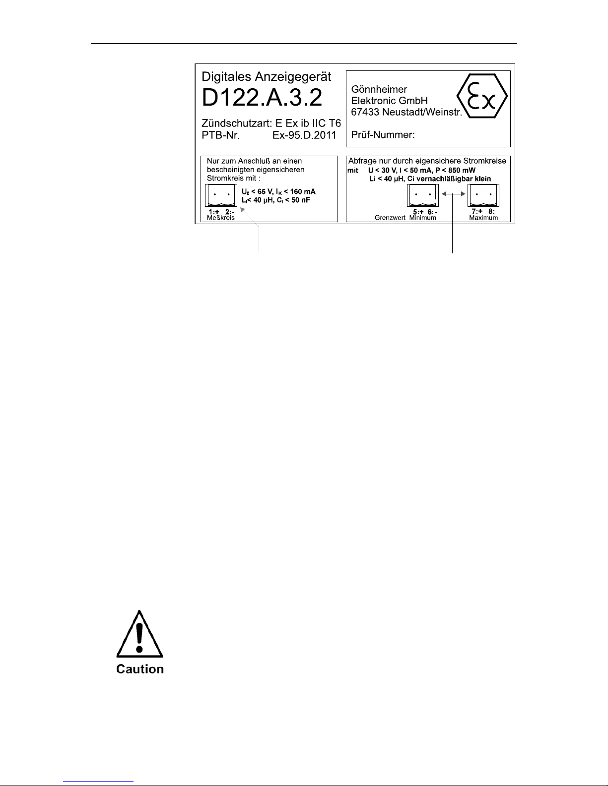
6.4 Marking ....................................................................................................................................27
6.5 Failure messages.....................................................................................................................28
6.6 Transport, Storing, Repairs und Disposal................................................................................28
6.7 Dimensions ..............................................................................................................................29
6.8 List of Parameters....................................................................................................................30
6.9 Index ........................................................................................................................................32
D122.A 2 Operation instructions Page 3
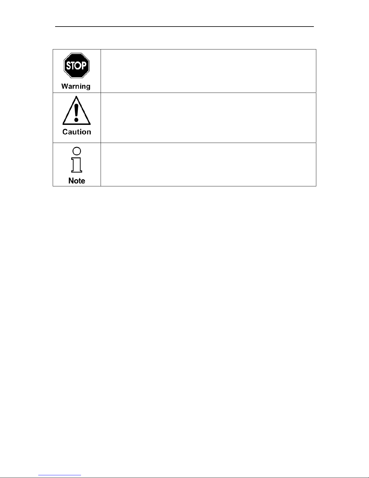
The symbols WARNING, CAUTION, NOTE
This symbol warns of a serious hazard. Failure to observe this warning may result in death or the destruction of property.
This symbol warns of a possible failure. Failure to observe this caution may result in the total failure of the device or the system or plant
to which it is connected.
This symbol highlights important information.

D122.A 2 Operation instructions Page 4
1 Operation instruction for Explosion protected device
Application and Standards
This instruction manual applies to explosion-protected control panels of type of protection
types below. This apparatus is only to be used as defined and meets requirements of EN 60
079 particularly EN60 079-14 "electrical apparatus for potentiality explosive atmospheres".
Use this manual in hazardous locations, which are hazardous due to gases and vapours according to the explosion group and temperature class as stipulated on the type label. When
installing and operating the explosion protected distribution and control panels you should observe the respective nationally valid regulations and requirements.
General Instructions
The device has to have a back-up fuse as stipulated. The mains connection must have a sufficient short circuit current to ensure safe breaking of the fuse. To achieve an impeccable and
safety device operation, please take care for adept transportation, storage and mounting, as
well as accurate service and maintenance. Operation of this device should only be implemented by authorised persons and in strict accordance with local safety standards.
The electrical data on the type label and if applicable, the "special conditions" of the test certificate TÜV 99 ATEX 1488 are to be observed.
For outdoor installation it is recommended to protect the explosion protected distribution and
control panel against direct climatic influence, e.g. with a protective roof. The maximum ambient temperature is 40°C, if not stipulated otherwise.
Intrinsically Safe Circuits
Erection instructions in the testing certificates of intrinsically safe apparatus are to be observed. The electrical safety values stipulated on the type label must not be exceeded in the
intrinsically safe circuit. When interconnecting intrinsically safe circuits it is to be tested,
whether a voltage and/or current addition occurs. The intrinsic safety of interconnected circuits
is to be ensured. (EN 60079-14, section 12)
Safety Measures: to read and to comply
Work on electrical installations and apparatus in operation is generally forbidden in
hazardous locations, with the exception of intrinsically safe circuits. In special cases
work can be done on non-intrinsically safe circuits, on the condition that during the
duration of such work no explosive atmosphere exists. Only explosion protected
certified measuring instruments may be used to ensure that the apparatus is voltage-free. Grounding and short-circuiting may only be carried out, if there is no explosion hazard at the grounding or short circuit connection.
Danger of static charge!
Clean only with humid cloth!
Do not open when an explosive dust atmosphere is present!

D122.A 2 Operation instructions Page 5
2 Digital Indicator D122.A
2.1 Short description
The digital Indicator D122 indicates measured values of intrinsically safe current circuits from 4 up to
20 mA in hazardous areas. The device is powered by measure current, therefore an extra power supply or batteries are unnecessary. The indicator measures the current, scales the measured value and
displays finally the result on the LCD.
For trend analysis, the measured signal is also be displayed on a 41 segment bargraph. It's possible
to scale the bargraph separately to the digital value. The indicator D122 is available in several housings.
Furthermore with alarm monitoring option the indicator has two intrinsically safe alarm outputs. These
outputs change their state, when the measured value exceeds his alarm limits. It’s possible to choose
open-circuit or closed-circuit connection.
Additional the alarm limits appear graphically on a second bargraph. On one look you’re sure that the
measured value is in its limits.
2.2 Features overview
2.2.1 Basic functions
• Loop-powered digital Indicator
• Connect like passive analogue indicators, voltage drop ca. 1V
• LC-Display up to 50 mm figure-height
• Scale by buttons and display
• Fast bargraph for trend observation (41 segments, refresh 4 times per sec-
ond)
• Separately scaleable Bargraph (Zoom)
• Several housings available (control panel- and field housing)
2.2.2 Options
• Alarm monitoring: two intrinsically safe alarm outputs and an additional limitbargraph on the display
• Limit-functions with hysteresis and time delay
• Field housing with additional (2
nd
) PG-Connector
2.3 Conformity with Standards
The explosion proof indicators type D122 meets requirements of listed standards in the attachment
(Declaration of conformity). They were developed, manufactured and tested in accordance with stateof-the-art engineering practice and ISO9001:2008.
D122.A 2 Operation instructions Page 6
2.4 Internal zener barrier option
Devices with type code D122.A.x.x.BM
The standard digital indicator D122 works exclusively in intrinsically safe 4..20 mA
current circuits (Ex i). If the concerned measure current circuit is not intrinsically safe,
an extra zener barrier or an isolated interface and a long additional cable to the interface outside the hazardous area and back is needed.
In those cases, the option integrated zener barrier
is very practical, because the interface is build in. A
further advantage of an indicator with this option is
that the intrinsical safety proof is not required.
The ignition protection is Ex m [ib] IIC T6 at ambient temperature of 45°C, Ex m [ib] IIC T5 at 60 °C
respectively.
The terminal voltage in the measure circuit with
internal zener barrier option is about 2 V.
2.5 Integrated 2-wire transmitter option
Devices with type code D122.A.x.x.MU
Using the integrated 2-wire transmitter for head mounting option, the D122 has an interface to an arbitrary sensor e.g. a PT 100.
The digital indicator series with field housing can be equipped with a customized intrinsically safe 2wire transmitter for head mounting, according to DIN 43729 type B (max. height = 30 mm). With this
option, it is possible to connect a sensor, e.g., a PT 100 directly to the digital indicator D122.
Customer can specify or provide the desired transmitter by order.
This option is only available for indicators with field housing. The depth of the field housing is in-
creased from 64 to 82 mm.
A combination with the internal zener barrier option is not possible.

D122.A 3 Installation and Connection Page 7
2.6 Special software option
Indicators D122.AS as well as totalizers D122.ZS have a special software option. With this option, it is
possible to use these devices in any individual cases of measurement and indication.
2.7 Curve fitting
The curve fitting software indicates the measure current in a non-linear way. Consider the application of a filling-level meter for a sphere-tank. The measure current is linear to the filling-height of the
liquid. Nevertheless, the function between the filling-height and the volume is non-linear, as shown in
the figure below.
To get the correct quantity indication you require a list of points, which shows the connection between measure current and associated quantity inside of the tank. The curve fitting software of the
D122.XS interpolates the curve between these points on your choice in a linear or a square way.
The linear interpolation generates imaginary straight lines between the selected points. A
value on this line will be calculated on base of his distance to the previous selected point.
This kind of interpolation requires 17 points to scale 4 up to 20 mA.
On the other hand, the square interpolation needs a list of 33 points, but it approximates
the original curve much better than the linear one, so the error between the original curve
and the interpolated curve is much smaller.
To put in the list of selected point enter the (extended) scale menu. The device displays the measure
current and you have to enter the associated display value. See also related flow diagram.
2.8 Square root-fitting
To program a square root-function, e.g., to display the flow through a aperture, a special square rootfitting feature is available. For this option, it is not necessary to enter a list of points, but just a startand a end-value (in previous example: associated flow by 4 and by 20mA measure current). The device calculates automatically the selected points for interpolation. Be prepared, this procedure will take
some time. See also related flow diagram.
D122.A 3 Installation and Connection Page 8
3 Installation and Connection
3.1 D122 with control panel housing
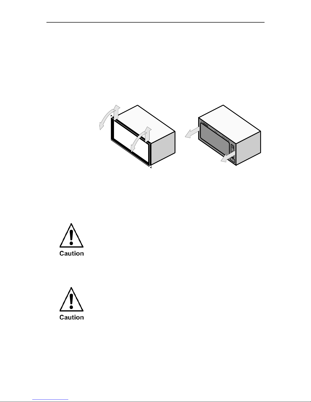
3.1.1 Installation control panel housing
The digital indicators D122.A.0 and D122.A.3 are predicated for installation in
a control panel.
How to insert
the dimension
symbol
Insert the dimension symbol (icon) before mounting. Do this by first removing
the front frame as shown in the figure at left. Now remove the front panel
from the housing as shown in the figure on the right.
Cut the desired dimension-symbol from the set and pull it into its intended
place on the right side of the panel. Make sure that the symbol is facing the
front. Replace the front panel and frame.
Fixing
Fix the indicator into the control panel with the intend cramps.
3.1.2 Connecting D122 with control panel housing
Connect the indicator only to intrinsically safe
4..20 mA current circuits.
The terminals of the indicators in the control panel housing are shown in figure 1. The terminals 5,6 and 7,8 are absent by indicators without alarm monitoring.
Please regard the terminal maximum values of the
attached EC- type certificate TÜV 99 ATEX 1488 .
D122.A 3 Installation and Connection Page 9
Intrinsically safe measure circuit 4 ..20 mA Alarm monitoring option
Terminals 1,2 terminals 5,6 low alarm
terminals 7,8 high alarm
Figure 1: Terminals by indicators with control panel housing
3.2 Field housing D122.A.5 and D122.A.6
When mounting the housing box on a wall, be sure that it is securely supported by anchoring the screws into a stud or other solid surface.
How to insert
the Dimensionsymbol
First, cut the desired dimension symbol out of the set. Then pull off the four
screws of the cap and remove the cap from the housing.
Now push the prepared dimension-symbol into the dimension-symbol-slot.
Make sure that the symbol is facing the front.
The dimension-symbol-slot lies below the display, on the internal side of the
cap.
Finally replace the cup on the housing.
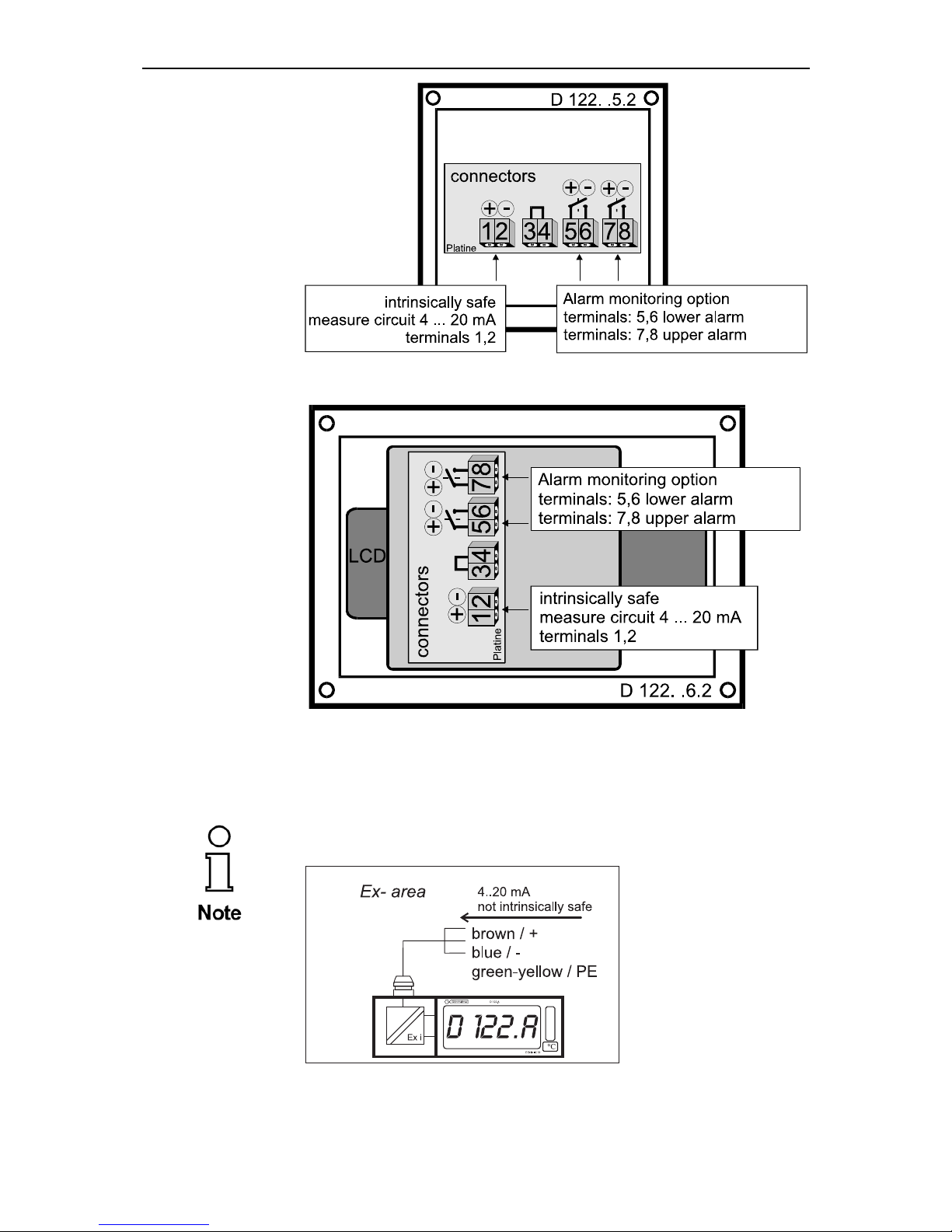
3.2.1 Connection D122 with field housing
The terminals of the indicators with field housing are inside. The placement of
the terminals is shown at the following figures.
Figure 2 shows the terminals of the indicator D122.A.5. Figure 3 shows the
terminals of the indicator D122.A.6.
The terminals 5,6 and 7,8 are absent by indicators without alarm monitoring.
Please regard the terminal maximum values of the
attached EC- type certificate TÜV 99 ATEX 1488 .
D122.A 3 Installation and Connection Page 10
Figure 2: Terminals of the indicator D122.A.5
Figure 3: Terminals of the indicator D122.A.6
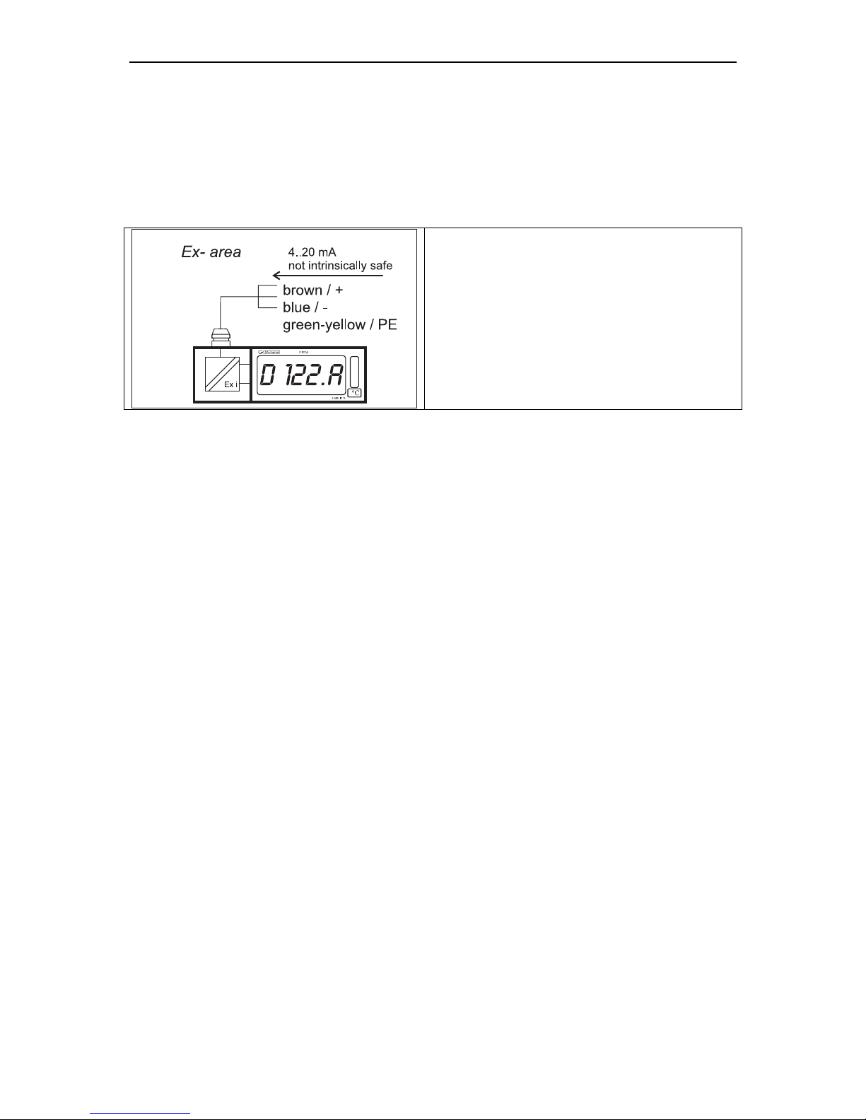
3.3 Connecting D122A with zener barrier option
Connect the D122.A.x.x.BM to a non intrinsically safe measure signal.
Inside of hazardous area the D122A.x.x.BM cable must be connected in a
certificated Ex e-connection box.
Figure 4: Connection of D122.A.x.x.BM
D122.A 3 Installation and Connection Page 11
Cable Connection
Cable
Brown +
colors
Blue Green yellow PE
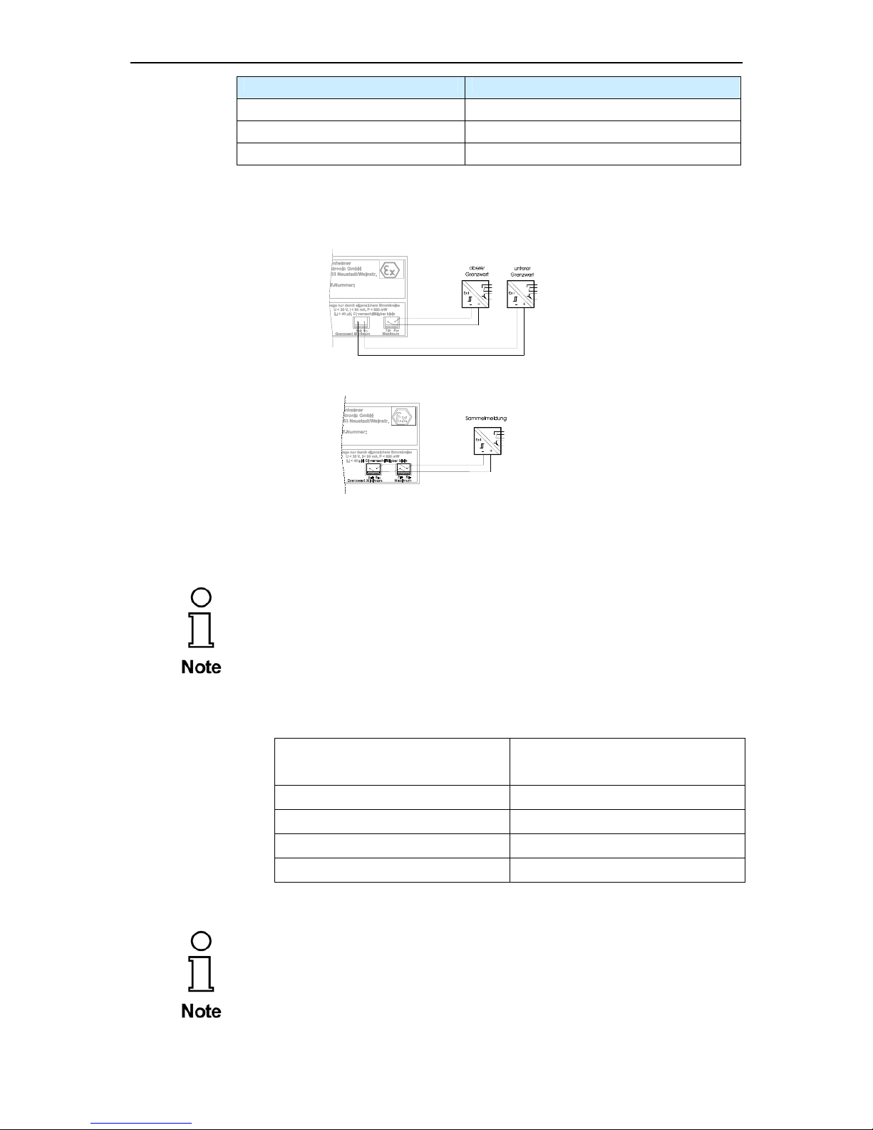
3.4 Connecting D122A with limit terminals (terminals 5/6 + 7/8)
Devices with type code D122.x.x.2.x
Figure 5 : limit monitoring with D122.x.x.2.x
3.5 Initial operation
After connecting, a display test (all segments of the display are turned on)
appears immediate during one second. Thereupon the display shows the
software version of the indicator.
3.5.1 Default parameters
The following parameters are active ex works:
Scaling (display and bargraph)
4 mA curent -> 4.00
20 mA current -> 20.00
Limits
Low: 4.00 mA / High: 20.00 mA
Hysteresis / Delay
0.10 / 0 sec.
alarm outputs (alarm monitoring)
circuit-opening connection
Code words
CODE1: 0001 / CODE2: 0002
3.5.2 Ex works settings – Device reset
Press the Enter- and Right-button during the start sequence to
reactivate the default parameters. (Hardware-Reset)
A reset activates also the ex works calibration.
D122.A 4 Manual Page 12
4 Operating manual
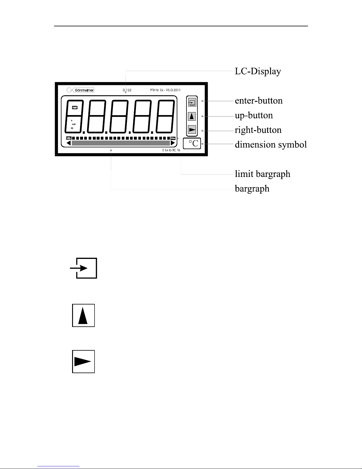
4.1 Front view
4.2 Keyboard
On the front side of the indicator are tree buttons with several function symbols. With these tree buttons, the user can activate each function and enter all parameters for any individual setting.
The buttons are named by their functions:
Enter-button
Pressing the enter-button starts the input menu.
In general, the enter-button activates the menu item or accepts the manipulated value of a parameter.
Up-button
Functions of the up-button are:
1. current control button
2. modification of the selected figure
3. pass menu items
Right-button
Functions of the right-button are:
1. change the display to limit view
2. select figures
3. pass menu items
D122.A 4 Manual Page 13
4.3 Configuration
It is easy to set the parameters and change the configuration of the indicator. The parameters are
logically grouped by a menu structure. See also the appropriate flow diagram in the appendix.
Indicators without the alarm monitoring option have not got the
corresponding menu items.
Note flow charts
SET
The Input views in the flow diagrams have additional boxes in
their background, because the Input views may be changed by
pressing any of the buttons.
The procedure, to enter a value, is shown in the flow diagram
‘Value input menu’, see figure 13.
) Normal state
After connecting, the indicator D122 starts to initialise its configuration. The configuration data is stored in an internal EEPROM
due to the previous run. By the first start, the D122 indicator initialises the default configuration.
Directly past starting sequence the indicator begins to display the
measured current digital and analogous on the bargraph. This
state is called the ‘normal state’ of the D122 and the indicator is
also ready for inputs.
(See also flow diagram in figure 9)
) current control
Pressing and holding the up-button (current control button) the
display shows the present current and the [mA] symbol.
(See also flow diagram in figure 9)
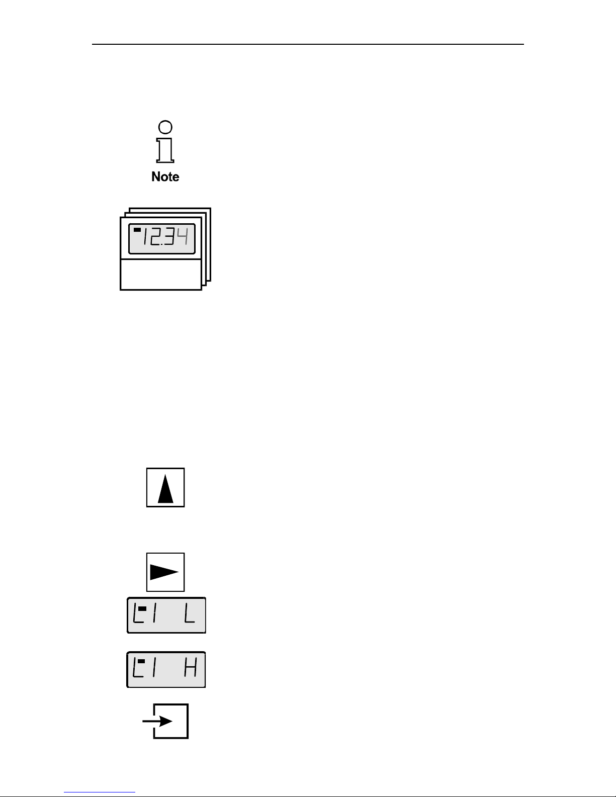
) limit view menu
(Only for indicators with the alarm monitoring option)
One touch on the right-button starts the limit view menu.
(See also flow diagram in figure 9)
SET
The display [limit low] appears on the screen. Press the enter-
button to watch the value of the lower limit.
SET
For passing the low limit press the right-button. The menu
changes to the high limit. The screen shows now [limit high]. Confirm with the enter-button to display the value of the upper limit.
Pressing the right-button for a second time quits the limit view
menu and returns to normal state.
During watching the limit values it is possible to manipulate them
by pressing the enter-button. The view changes to the
D122.A 4 Manual Page 14
; Edit mode.
SET
A blinking segment appears below the sign place. Pressing the
right-button selects the figure and the up-button increments the
selected figure. To accept the new limit value, press the enter-
button.
(See also flow diagram in figure 13)
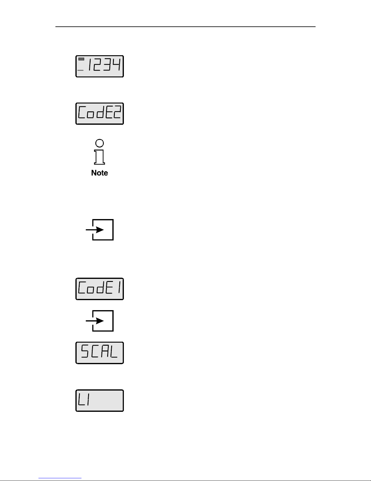
; Code protection
Max
Before the menu gets to the edit mode the code 2 must be entered, to prevent a modification by unauthorised persons.
Entering a wrong code word stops the limit view menu immediately.
The default code 2 is [0002].
The interrogation of code 2 can be switched off by modifying
the code 2 to [0000]. For this reason the flow diagram shows the
code interrogation in stroked dots.
4.3.1 How to set the parameters
;
(See also flow diagram in figure 11)
Back in the normal state of the indicator we start the
) Input menu
by pressing the enter-button.
The configuration of the indicator is protected against ma-
nipulations by unauthorised persons with the code 1. To get the
input menu enter the code 1 default [0001].
It’s impossible to switch off the code 1 interrogation.
After entering the right code word the indicator proposes to join
the
Scale menu. The figure on the left hand appears on the screen.
To scale the measured current, the bargraph and to set the
decimal point join the scale menu by confirming with the enter-
button.
See also flow diagram in figure 12).
To pass the scale menu press the right-button. The following sub
menu is called limit menu. This menu is naturally only available
for indicators with the alarm monitoring option.
In the limit menu the user enters the limits, as well as the hysteresis and the time delay of the alarm outputs.
(See also flow diagram in figure 15)
D122.A 4 Manual Page 15
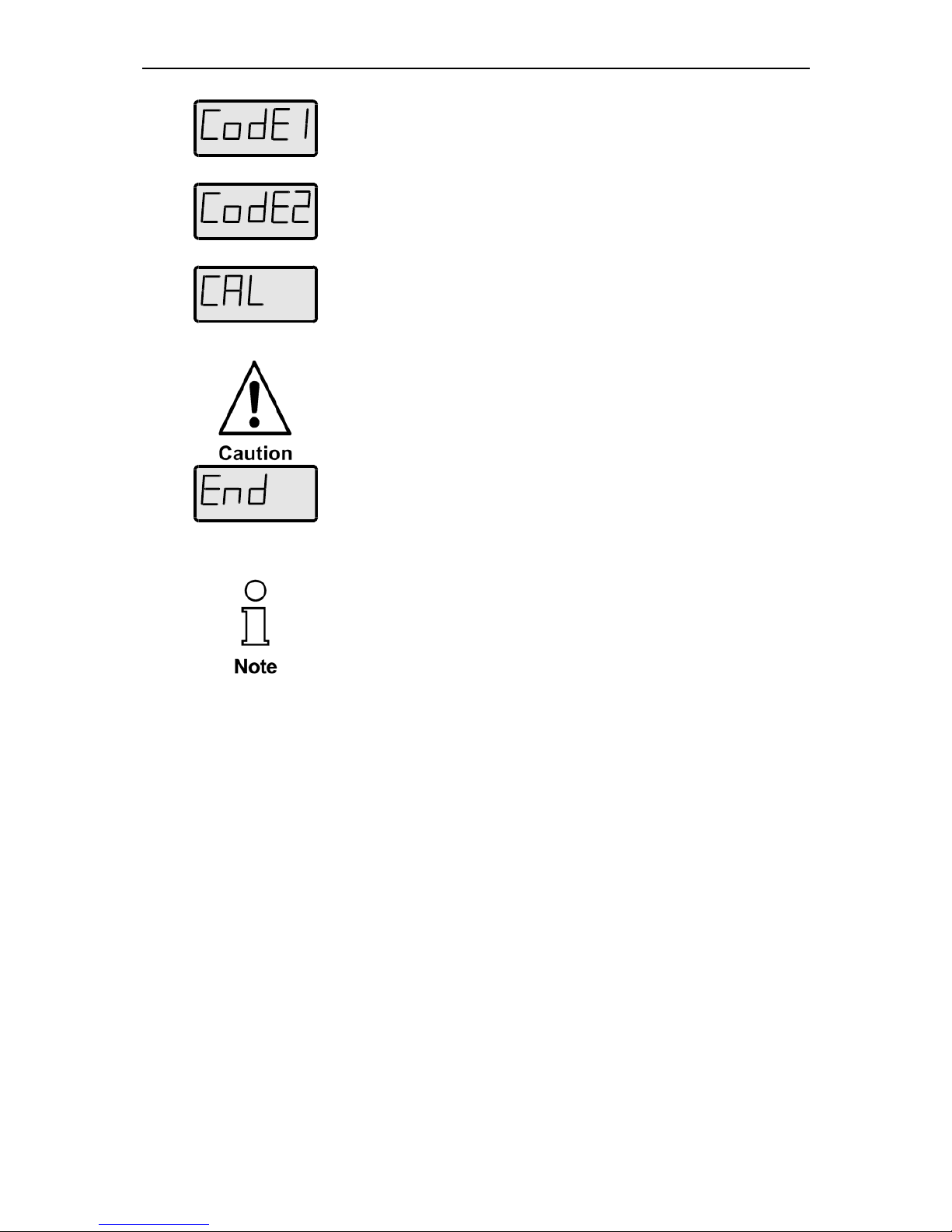
Max
The next two following items allow to manipulate the words for
code 1 and code 2. The enter-button confirms the input and the
corresponding code appears in edit mode.
Remember that the code word [0000] switches off the code 2.
Finally it’s possible to calibrate the indicator with the following
sub menu called calibration menu.
(See flow diagram in figure 16)
The indicator is already calibrated ex-works.
In general, a further calibration is not necessary and only
experienced persons are allowed to calibrate it. False calibration will result senseless Indication.
To start calibration enter the code word 0123.
Now we reach the end of the input menu. Confirm the end with
the enter-button. The indicator switches back to normal state.
If you want to repeat the input menu, press the right-button.
If an invalid value is entered for any of the parameters, you will
not be able to quit the input menu. Instead, the program switches
automatically into edit mode to the found valid value.
 Loading...