

Page 1
Proprietary Information - Confidential
DO001152
GoBeam-8000
Assembly Instruction
Revision:
1.1
Page: 1 out of 16
Approval Date:
16.12.2013
Effective
Date:
16.12.2013
Update by:
Approved by:
Oleg Einem
Nimrod Tenne
Sharon Ashkenazi
Page 1 of 16
DO001152 REV 1.1
Printed version are uncontrolled
Revision History
Revision
Date
Changes
Modified By
Approved By
1.0
09.12.13
Release Work Procedure
Oleg Einem
Nimrod Tenne
1.1
06.01.14
Fixed
Oleg Einem
Sharon
Ashkenazi
Page 2

Proprietary Information - Confidential
DO001152
GoBeam-8000
Assembly Instruction
Revision:
1.1
Page: 2 out of 16
Approval Date:
16.12.2013
Effective
Date:
16.12.2013
Update by:
Approved by:
Oleg Einem
Nimrod Tenne
Sharon Ashkenazi
Page 2 of 16
DO001152 REV 1.1
Printed version are uncontrolled
Table of Content
Revision History ................................................................................................................................ 1
1. Introduction ................................................................................................................................ 3
2. Required Tools ........................................................................................................................... 3
3. General Instructions ................................................................................................................... 3
4. Mechanical Assembly ................................................................................................................ 4
4.1. Heat Conductive Gap Fillers Gluing 4
4.2. Light pipes 5
4.3. Sealing Gasket. 5
4.4. Adhesive Membrane Vent Gluing 6
4.5. CPU board. 6
4.6. PS board. 7
4.7. Wireless mini PCI Boards 2.4GHz, 5GHz. 8
4.8. Mechanical Assembly. 10
4.9. Beam Forming. 11
4.10. Antennas. 13
4.11. Radom. 14
4.12. Sealing screw. 15
4.13. Ground Screw 15
4.14. Plug for ETH2 16
4.15. Labels Sticking 16
Page 3
Proprietary Information - Confidential
DO001152
GoBeam-8000
Assembly Instruction
Revision:
1.1
Page: 3 out of 16
Approval Date:
16.12.2013
Effective
Date:
16.12.2013
Update by:
Approved by:
Oleg Einem
Nimrod Tenne
Sharon Ashkenazi
Page 3 of 16
DO001152 REV 1.1
Printed version are uncontrolled
1. Introduction
This document describes in detail the assembly process of the GoBeam-8000 Top level Systems.
2. Required Tools
Automatic screw drivers with torque (for example “Delvo” DLV-7333 and DLV-7140).
Philips screw head bits size 1 and 2.
Hexagon head bit size 5mm.
PLCC Instructor.
3. General Instructions
3.1. Before assembling verify that all required items are in following conditions:
3.1.1. Parts are in correspondence with proper part numbers and revisions.
3.1.2. All items are in good condition, not damaged and fully clean.
3.1.3. Each component has relevant certificate, test report and approval.
3.1.4. Tools are calibrated, tested in time and approved for use.
3.1.5. Working place is properly equipped, clean and free of extraneous objects.
3.2. All assembly executors must carefully follow these instructions.
3.3. Unless otherwise specified use Soudure NET 9418 (Go P/n: MS000010) for cleaning and
degreasing.
3.4. Unless otherwise specified screws bit size and closing torque should be in accordance with the
following table:
Screw Size
M2
M3
M3 Nylon
M4
M5
Bit size
1
2
Required Torque
4 kg-cm
3.5 lb-In
6.9 kg-cm
6 lb-In
3.5 kg-cm
3 lb-In
17 kg-cm
14.8 lb-In
30 kg-cm
26 lb-In
Page 4

Proprietary Information - Confidential
DO001152
GoBeam-8000
Assembly Instruction
Revision:
1.1
Page: 4 out of 16
Approval Date:
16.12.2013
Effective
Date:
16.12.2013
Update by:
Approved by:
Oleg Einem
Nimrod Tenne
Sharon Ashkenazi
Page 4 of 16
DO001152 REV 1.1
Printed version are uncontrolled
4. Mechanical Assembly
4.1. Heat Conductive Gap Fillers Gluing
4.1.1. Stick items 2…6 to item 1 after previously cleaning related surfaces of
item 1.
Item
Description
Part No
QTY
1
Base
MC000471
1
2
Thermal Pad 50x25x2 mm
MC000500
2
3
Thermal PAD(45*7*1t)
MC000477
1
4
Thermal PAD(26*26*1t)
MC000478
1
5
Thermal PAD(7.5*6.5*1t)
MC000479
4
6
Thermal PAD(8*8*1t)
MC000480
2
Page 5
Proprietary Information - Confidential
DO001152
GoBeam-8000
Assembly Instruction
Revision:
1.1
Page: 5 out of 16
Approval Date:
16.12.2013
Effective
Date:
16.12.2013
Update by:
Approved by:
Oleg Einem
Nimrod Tenne
Sharon Ashkenazi
Page 5 of 16
DO001152 REV 1.1
Printed version are uncontrolled
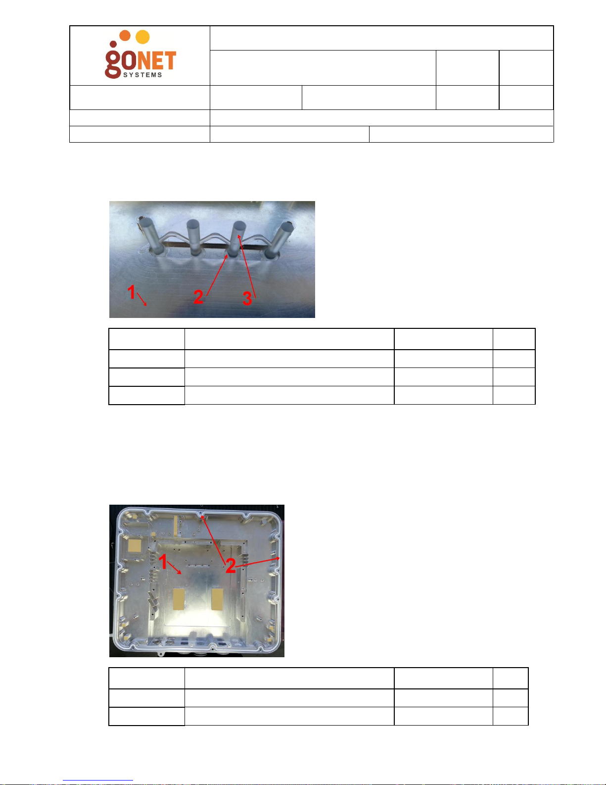
4.2. Light pipes
4.2.1. Paste the light pipes (item 3) to the item 1 by item 2 without holes
between body and light pipes.
4.3. Sealing Gasket.
Fit the Sealing Gasket (item 2) into the Body’s groove after previously applying
Grease MS000008.
Ensure that the gasket seats proper along the groove and any of its particles do
not get out.
Item
Description
Part No
QTY
1
Base
MC000471
1
2
Silicon
MS000022
0.08mL
3
Light Pipe
MC000483
1
Item
Description
Part No
QTY
1
Base
MC000471
1
2
O-Ring
MC000495
1
Page 6

Proprietary Information - Confidential
DO001152
GoBeam-8000
Assembly Instruction
Revision:
1.1
Page: 6 out of 16
Approval Date:
16.12.2013
Effective
Date:
16.12.2013
Update by:
Approved by:
Oleg Einem
Nimrod Tenne
Sharon Ashkenazi
Page 6 of 16
DO001152 REV 1.1
Printed version are uncontrolled
4.4. Adhesive Membrane Vent Gluing
Stick item 2 to item 1 after previously cleaning related surface of item 1.
4.5. CPU board.
4.5.1. Stick items 2, 3 to item 1 after previously cleaning related surfaces of
item 1.
Item
Description
Part No
QTY
1
Base
MC000471
1
2
Adhesive Membrane Vent
MC000030
1
Item
Description
Part No
QTY
1
PCB Holder
MC000472
1
2
Thermal PAD(38*18*1t)
MC000475
2
3
Thermal PAD(67*100*1t)
MC000476
1
1
2
Page 7

Proprietary Information - Confidential
DO001152
GoBeam-8000
Assembly Instruction
Revision:
1.1
Page: 7 out of 16
Approval Date:
16.12.2013
Effective
Date:
16.12.2013
Update by:
Approved by:
Oleg Einem
Nimrod Tenne
Sharon Ashkenazi
Page 7 of 16
DO001152 REV 1.1
Printed version are uncontrolled
4.5.2. Connect item 2 to item 1 and fasten it by item 3 and item 4 as shown in
the image.
4.6. PS board.
4.6.1. Connect item 2 to item 1 and fasten it by item 3 as shown in the image.
Item
Description
Part No
QTY
1
PCB Holder
MC000472
1
2
CPU board
BM000001-01
1
3
STAND OFF(M3x16L)
FS000122
3
4
SCREW (M3*8)
FS000080
8
Item
Description
Part No
QTY
1
CPU board
BM000001-01
1
2
Power Supply board
BM000002-01
1
3
SCREW (M3*8)
FS000080
3
Page 8

Proprietary Information - Confidential
DO001152
GoBeam-8000
Assembly Instruction
Revision:
1.1
Page: 8 out of 16
Approval Date:
16.12.2013
Effective
Date:
16.12.2013
Update by:
Approved by:
Oleg Einem
Nimrod Tenne
Sharon Ashkenazi
Page 8 of 16
DO001152 REV 1.1
Printed version are uncontrolled
4.7. Wireless mini PCI Boards 2.4GHz, 5GHz.
4.7.1. Remove the Product label from mini PCI Boards. (on PS side).
4.7.2. Connect item 2 to item 1 and fasten it by item 3 as shown. (also Mini PCI
2.4GHz and also Mini PCI 5GHz)
4.7.3. Connect 5 RF cables CB000272 to Conn 0-2 of Mini PCI 2.4GHz and
Mini PCI 5GHz.
Note: Only one RF cable that connected to Conn 2 of Mini PCI 2.4GHz must be
LONG: CB000273.
Item
Description
Part No
QTY
1
CPU board
BM000001-01
1
2
Mini PCI 2.4GHz (on left side of CPU)
WL000012
1
2
Mini PCI 5GHz (on right side of CPU)
WL000013
1
3
SCREW (M2*6)
FS000073
4
Key of Side for
mini PCI 2.4GHz
Page 9

Proprietary Information - Confidential
DO001152
GoBeam-8000
Assembly Instruction
Revision:
1.1
Page: 9 out of 16
Approval Date:
16.12.2013
Effective
Date:
16.12.2013
Update by:
Approved by:
Oleg Einem
Nimrod Tenne
Sharon Ashkenazi
Page 9 of 16
DO001152 REV 1.1
Printed version are uncontrolled
4.7.4. Connect item 3 to item 1 and fasten it by item 2 as shown. (also for Mini
PCI 2.4GHz and also for Mini PCI 5GHz)
Item
Description
Part No
QTY
1
PCB Holder
MC000472
1
2
SCREW (M3*8)
FS000080
4
3
PCIE HOLDER
MC000482
2
Key of Side for
mini PCI 5GHz
Page 10
Proprietary Information - Confidential
DO001152
GoBeam-8000
Assembly Instruction
Revision:
1.1
Page: 10 out of 16
Approval Date:
16.12.2013
Effective
Date:
16.12.2013
Update by:
Approved by:
Oleg Einem
Nimrod Tenne
Sharon Ashkenazi
Page 10 of 16
DO001152 REV 1.1
Printed version are uncontrolled
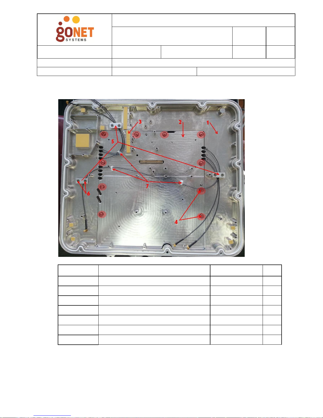
4.8. Mechanical Assembly.
4.8.1. Place item 2 on item 1 and fasten by items 4.
4.8.2. Stick items 3 to item 2 as shown in the image after previously cleaning
related surfaces of item 2.
4.8.3. Insert item 7 in item 2 as shown in the image.
4.8.4. Position RF cables in items 7 and fix them with item 5 and item 6 as
shown in the image.
Item
Description
Part No
QTY
1
Base
MC000471
1
2
PCB Holder
MC000472
1
3
Thermal PAD(45*7*1t)
MC000477
1
4
SCREW (M4*8)
FS000123
10
5
Cable Holder
MC000484
3
6
SCREW (M3*5)
FS000126
6
7
CABLE HOLDER(MWS1)
MC000485
3
Page 11

Proprietary Information - Confidential
DO001152
GoBeam-8000
Assembly Instruction
Revision:
1.1
Page: 11 out of 16
Approval Date:
16.12.2013
Effective
Date:
16.12.2013
Update by:
Approved by:
Oleg Einem
Nimrod Tenne
Sharon Ashkenazi
Page 11 of 16
DO001152 REV 1.1
Printed version are uncontrolled
4.9. Beam Forming.
4.9.1. Position Beam Forming board on back side of body and connect RF
cables of 5GHz as shown in the image.
4.9.2. After connecting cables 5GHz, shift longest RF cables of 5GHz and fix
in another holder as shown in the image.
4.9.3. Connect RF cables of 2GHz as shown in the image.
Page 12

Proprietary Information - Confidential
DO001152
GoBeam-8000
Assembly Instruction
Revision:
1.1
Page: 12 out of 16
Approval Date:
16.12.2013
Effective
Date:
16.12.2013
Update by:
Approved by:
Oleg Einem
Nimrod Tenne
Sharon Ashkenazi
Page 12 of 16
DO001152 REV 1.1
Printed version are uncontrolled
4.9.4. Position item 2 on item 1 using alignment pins as shown.
4.9.5. Fasten Beam Forming Board (item 2) with item 6, item 3 and item 4 as
shown in the image.
4.9.6. Screw item 5 in item 2.
4.9.7. Stick item 7 to item 2 as shown in the image.
Item
Description
Part No
QTY
1
Base
MC000471
1
2
Beam Forming board
BA000041-01
1
3
STAND OFF (M3*3.5)
FS000128
9
4
Standoff M3x8
FS000127
13
5
Standoff Nylon M-F M3x8 Hex 4.5
FS000129
3
6
SCREW (M3*8)
FS000080
16
7
Rubber Pad(D12.7*3.5t)
MC000494
1
1 2 5 7 4 3 6
Page 13

Proprietary Information - Confidential
DO001152
GoBeam-8000
Assembly Instruction
Revision:
1.1
Page: 13 out of 16
Approval Date:
16.12.2013
Effective
Date:
16.12.2013
Update by:
Approved by:
Oleg Einem
Nimrod Tenne
Sharon Ashkenazi
Page 13 of 16
DO001152 REV 1.1
Printed version are uncontrolled
4.10. Antennas.
4.10.1. Position item 2 and item 3 on item 1 and tighten items 4.
4.10.2. Fasten item 3 by item 5 as shown in the image.
Item
Description
Part No
QTY
1
Beam Forming board
BA000041-01
1
2
RF director 5GHz
PC000126
1
3
RF director 2GHz
PC000127
1
4
Screw Pan M3x5
FS000125
22
5
Screw Nylon Pan Phi Head M3x5
FS000130
3
Page 14
Proprietary Information - Confidential
DO001152
GoBeam-8000
Assembly Instruction
Revision:
1.1
Page: 14 out of 16
Approval Date:
16.12.2013
Effective
Date:
16.12.2013
Update by:
Approved by:
Oleg Einem
Nimrod Tenne
Sharon Ashkenazi
Page 14 of 16
DO001152 REV 1.1
Printed version are uncontrolled
4.11. Radom.
4.11.1. Position Cover (MC000473) on the unit and invert the unit with
Cover.
4.11.2. Screw items 2 into item 1.
Note: Only one screw (item 3) that placed as shown in the image must be keyed.
Item
Description
Part No
QTY
1
Base
MC000471
1
2
SCREW (M4*14)
FS000070
12
3
Screw with key
FSxxxxxx(TBD)
1
Page 15

Proprietary Information - Confidential
DO001152
GoBeam-8000
Assembly Instruction
Revision:
1.1
Page: 15 out of 16
Approval Date:
16.12.2013
Effective
Date:
16.12.2013
Update by:
Approved by:
Oleg Einem
Nimrod Tenne
Sharon Ashkenazi
Page 15 of 16
DO001152 REV 1.1
Printed version are uncontrolled
4.12. Sealing screw.
After sealing test (if passed) plug up tapped hole in Body by Self Sealing Screw
FS000004.
4.13. Ground Screw
Screw items 2 with item 3 into item 1.
Item
Description
Part No
QTY
1
Base
MC000471
1
2
Screw M5x10
FS000005
1
3
Toothed Lock M5
FS000020
2
Page 16

Proprietary Information - Confidential
DO001152
GoBeam-8000
Assembly Instruction
Revision:
1.1
Page: 16 out of 16
Approval Date:
16.12.2013
Effective
Date:
16.12.2013
Update by:
Approved by:
Oleg Einem
Nimrod Tenne
Sharon Ashkenazi
Page 16 of 16
DO001152 REV 1.1
Printed version are uncontrolled
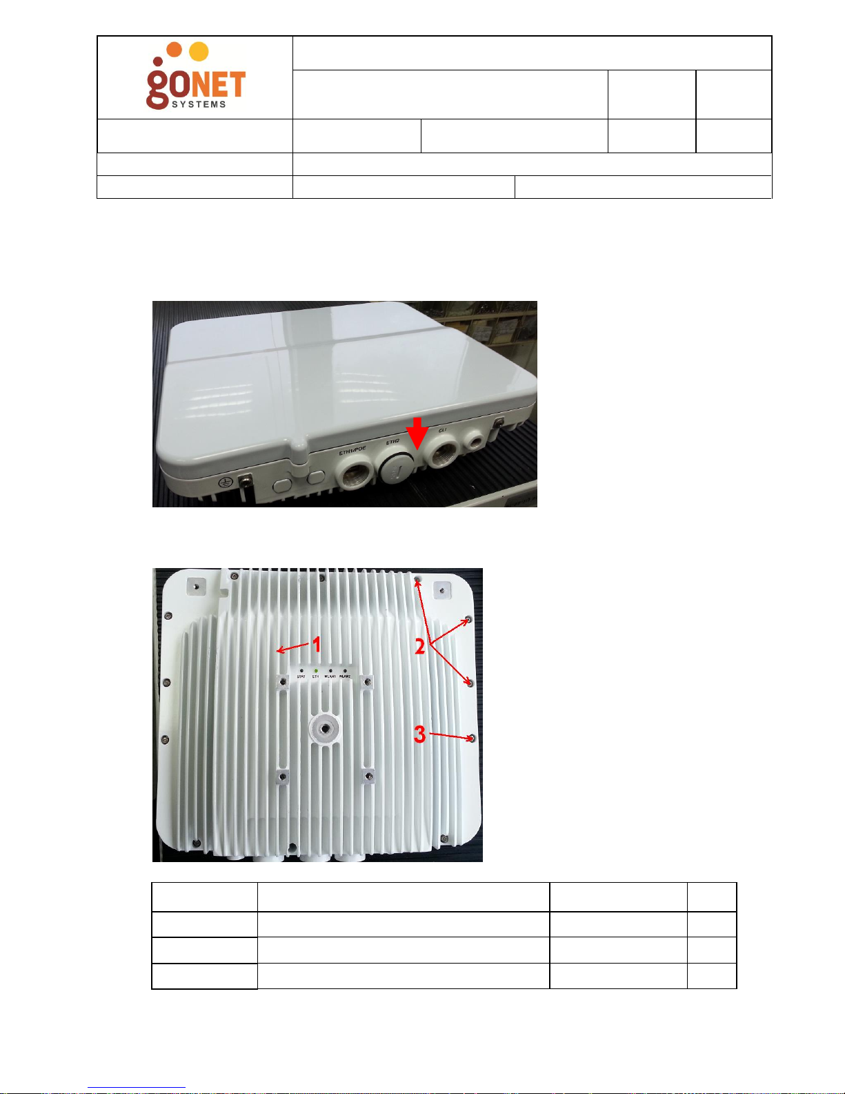
4.14. Plug for ETH2 and CLI.
Manually screw items 2 into item 1 in place of ETH2 and CLI.
4.15. Labels Sticking
Stick Labels (items 2) on two sides of item 1 after previously cleaning
appropriate surfaces of item 1.
Item
Description
Part No
QTY
1
Base
MC000471
1
2
Plug for ETH2 and CLI
CNxxxxxx(TBD)
2
Item
Description
Part No
QTY
1
Base
MC000471
1
2
Label
LBxxxxxx(TBD)
2
2
1
 Loading...