

GoBeam8000F Quick Installation Guide
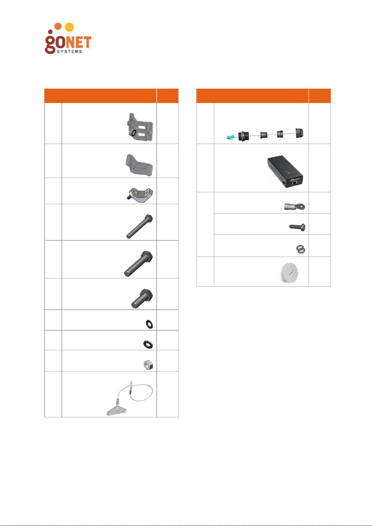
Description
Qty
A
Wall/Pole Bracket
1
B
Clamping Bracket
1
C
‘L’ Adapter Wall/Pole Mount
1
D
Hex Bolt M8x70
2
E
Hex Bolt M8x40
1
F
Hex Bolt M8x25
1
G
Flat Washer M8
4
H
Spring Washer M8
4
I
Nut M8
1
J
Safety Cable
1
Description
Qty
K
Waterproof RJ45 connector
2
L
Power Injector
1
M
Ring Terminal
1
Ground Screw
1
Lock Washer
2
N
Gland Cap
2
Components Included in the Package
Precaution
本製品に同梱いたしております電源コードセットは、本製品専用です。本電源コードセットは本製品
以外の製品ならびに他の用途でご使用いただくことは出来ません。製品本体には同梱された電源コー
ドセットを使用し、他製品の電源コードセットを使用しないでください。
UM000018 Rev 1.0 Copyright © 2014 GoNet Systems Ltd. All rights reserved.
GoBeam8000F Quick Installation Guide
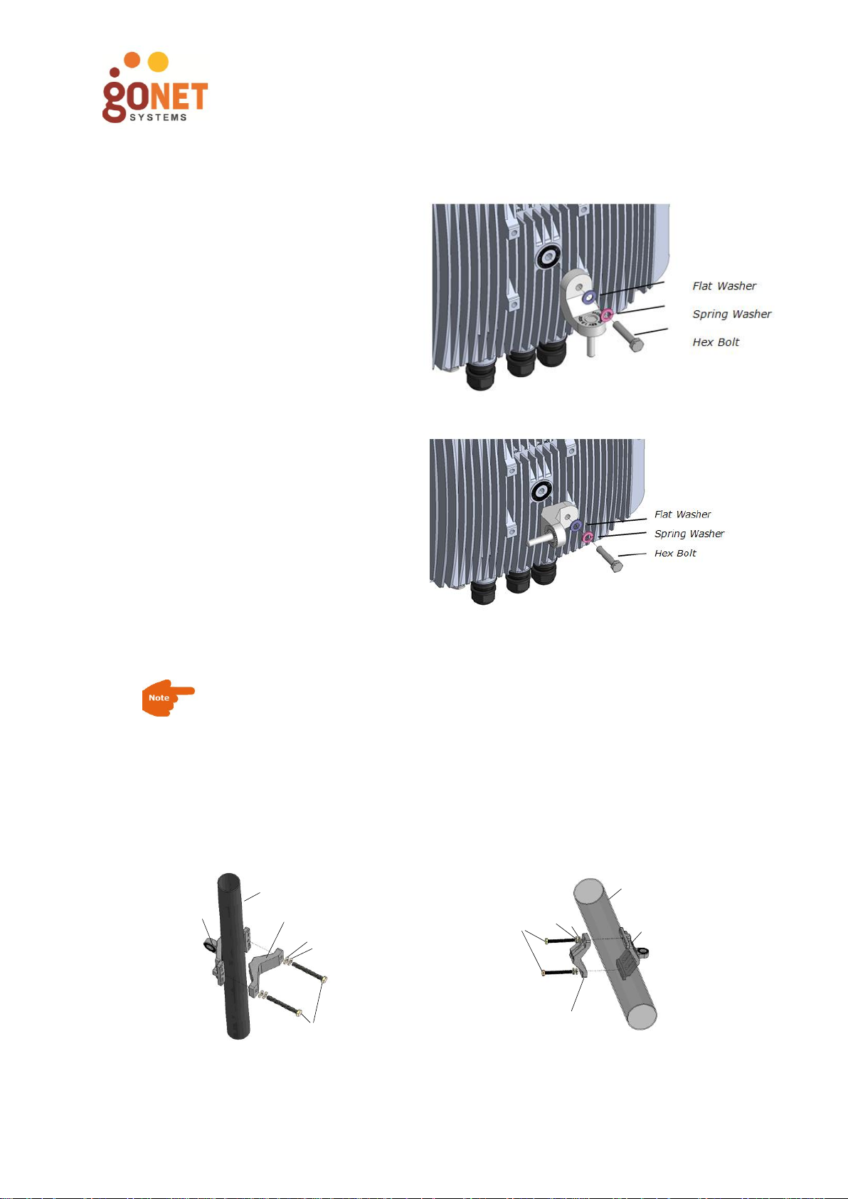
Horizontal Installation
Connect the ‘L’ Adaptor to the
GoBeam 8000 Unit.
Vertical Installation
Connect the ‘L’ Adaptor to the
GoBeam 8000 Unit.
Narrow Pole (1”-1.75” diameter)
B
Pole
A
H
E
I
Normal Pole (1.75”-3” diameter)
Pole
A
E
B
H
I
1. Assemble the ‘L’ Adapter
2. Install the Mounting Brackets
When mounting the GoBeam 8000, the pole or wall mounting on must
support a minimum of 61.6 lbs (28 kg). In addi tion, the pole or wall
mounting on must support the wind load from the GoBeam 8000. For
example, the wind load at a wind velocity of 100 mph (160 km/h) is
24.2 lbs (11 kg) and the wind load at a wind velocity of 165 mph
(264 km/h) is 66.1 lbs (30 kg).
UM000018 Rev 1.0 Copyright © 2014 GoNet Systems Ltd. All rights reserved.

GoBeam8000F Quick Installation Guide
Large Pole (larger than 3” diameter)
Stainless
Steel Hose
Clamp
A
Pole
Wall Mounting Bracket
Horizontal Pole Mounting
Vertical Pole Mounting
3. Installing the Safety Cable
1. Wrap the safety cable around the pole and
insert the mounting plate through the
cable loop.
2. Attach the mounting plate to the
GoBeam 8000 unit using the
hexagonal bolts.
UM000018 Rev 1.0 Copyright © 2014 GoNet Systems Ltd. All rights reserved.

GoBeam8000F Quick Installation Guide
4. Ground the GoBeam 8000 Unit
Connect the 10 AWG
grounding cable before
connecting any other
cables. When removing
the GoBeam 8000, the
grounding cable should
be the last cable
removed.
5. Connect the Ethernet PoE
Pin #
Signal
1
Data
2
Data
3
Data
4
48V (+)
5
48V (+)
6
Data
7
48V (-)
8
48V (-)
6. Connect the 1Gbps Network Connection
Pin #
Signal
Color
1
BI_DA+
white & green
2
BI_DA-
green
3
BI_DB+
white & orange
4
BI_DC+
blue
5
BI_DC-
white & blue
6
BI_DB-
orange
7
BI_DD+
white & brown
8
BI_DD-
brown
Ethernet
Network
1 Gb
UM000018 Rev 1.0 Copyright © 2014 GoNet Systems Ltd. All rights reserved.

GoBeam8000F Quick Installation Guide
7. Regulatory Information
This device complies with Part 15 of the FCC Rules. Operation is subject to the following
two conditions: (1) this device may not cause harmful interference, and (2) this device
must accept any interference received, including interference that may cause undesired
operation.
The Part 15 radio device operates on a non-interference basis with other devices
operating at this frequency when using its antennas.
Any changes or modifications not expressly approved by GoNet Systems could void the
user's authority to operate the equipment.
The antennas used for this transmitter must not be co-located or operating in
conjunction with any other antenna or transmitter.
This equipment complies with the FCC RF radiation exposure limits set forth for an
uncontrolled environment. This equipment should be installed and operated with a
minimum distance of 20cm between the radiator and any part of any person.
The antennas used for this transmitter must be fixed mounted on indoor or outdoor
permanent structures with a separation distance indoor network device.
The antennas used have an N-Type connector in compliance with FCC 15.203 Antenna
Requirement.
This device must be installed according to the latest version of the country national
electrical codes. For North America, equipment must be installed in accordance to the
applicable requirements in the US National Electrical Code and the Canadian Electrical
Code.
UM000018 Rev 1.0 Copyright © 2014 GoNet Systems Ltd. All rights reserved.
 Loading...