

GoBeam 5100/6100
Installation Guide

This page is intentionally left blank.

Trademarks and Licensing Agreement
© 2012 GoNet Systems Ltd. All rights reserved.
All information contained in this document is protected by
international copyright treaties. No information may be copied or
reproduced without the express written consent of GoNet Systems
Ltd.
GoNet Metro Broadband Wireless, GoNet GoBeam, GoNet MBW,
WLAN Sector Base Station, WLS, GoNet WLAN Pico Base Station,
WLP, GoNet Wireless Network Controller, and WNC are all
trademarks of GoNet Systems Ltd.
Any duplication, transmission by any method, or storage in an
information retrieval system of any part of this publication for
other purposes other than those stated above is strictly prohibited
without the specific written permission of GoNet Systems Ltd. This
includes, but is not limited to, transcription into any form of
computer system for audio, text, print, or visual retrieval. All
rights under federal copyright laws and international laws will be
strictly enforced.
All other trademarks and registered trademarks are the property
of their respective owners.
GoNet Systems Ltd.
Email: support@gonetworks.com
Document #: 3600-112012-2
GoBeam 5100/6100 Installation Guide i

Regulatory Information
FCC-15 User Information
1. This device complies with Part 15 of the FCC Rules. Operation
is subject to the following conditions:
2. This device may not cause harmful interference, and this
device must accept any interference received, including
interference that may cause undesired operation.
This equipment has been tested and found to comply with the
limits of a Class B digital device, pursuant to Part 15 of the FCC
Rules. These limits are designed to provide reasonable protection
against harmful interference when the equipment is operated in a
residential environment, this equipment generates, uses, and
radiates radio frequency energy, and if not installed and used in
accordance with the instructions, may cause harmful interference.
However, there is no guarantee that interference will not occur.
To meet regulatory restrictions, the outdoor access point must be
professionally installed.
The Part 15 radio device operates on a non-interference basis with
other devices operating at this frequency when using its antennas.
Any changes or modifications not expressly approved by GoNet
Systems could void the user's authority to operate the equipment.
The antennas used for this transmitter must not be co-located or
operating in conjunction with any other antenna or transmitter.
ii GoBeam 5100/6100 Installation Guide
Notices
Read and understand the following before installation.
• Equipment surfaces may become hot during
operation. Do not touch hot surfaces of the
system. Touching a hot surface may result in
serious personal injury, including burning of skin or
flesh.
• The GoBeam 5100/6100 is intended to be
grounded. Ensure that the GoBeam 5100/6100 is
connected to earth ground during normal use.
• This product must be connected to a power-over-
Ethernet (PoE) IEEE 802.3af compliant power
source or an IEC60950 compliant limited power
source.
• This unit is not intended for use in marine
environments.
• Use 48Vdc LPS (according IEC/EN/UL 60950-1
section 2.5) power supply as power injector.
GoBeam 5100/6100 Installation Guide iii

Table of Contents
Introduction .................................................................................. 1
GoBeam Model Numbers ............................................................ 1
GoBeam 5100 ................................................................................ 2
GoBeam 5100 Features ............................................................. 2
GoBeam 5100 Package Components ........................................... 2
GoBeam 6100 ................................................................................ 3
GoBeam 6100 Features ............................................................. 3
GoBeam 6100 Package Components ........................................... 3
GoBeam 5100/6100 Safety Information ............................................ 4
RF Exposure ............................................................................. 4
Installation Codes ..................................................................... 4
Information de sécurité pour GoBeam 5100/6100 .............................. 5
Exposition aux fréquences RF ..................................................... 5
Paratonnerre pour GoBeam 5100/6100 ....................................... 5
Codes d'installation ................................................................... 5
Installation .................................................................................... 6
Installation Process ................................................................... 6
Site Survey ........................................................................ 6
Assembling the GoBeam 5100 Antennas ...................................... 7
GoBeam 5100 Wi-Fi antennas ............................................... 7
GoBeam 5100 Mesh antennas ............................................... 8
Assembling and Mounting the GoBeam 5100/6100........................ 8
Hardware and Connectors Installation Tools .......................... 11
Mounting Adapters ............................................................. 11
Mounting Brackets .............................................................. 13
Mounting the GoBeam 5100/6100 on a horizontal pole ........... 15
Mounting the GoBeam 6100 on a vertical pole ....................... 15
Installing the Safety Cable .................................................. 16
Assembling the Optional Mesh Antennas .......................................... 17
Installation Tools ..................................................................... 19
Attaching Antenna Cables to L-Bracket ....................................... 19
Mounting the L-Bracket to the Chassis ........................................ 20
Attaching Mesh Antennas .......................................................... 20
Cable Connections ................................................................... 21
Cable Installation Tools ....................................................... 22
Grounding Cable ................................................................ 23
Power over Ethernet (PoE) Connection .................................. 24
Serial Connection ............................................................... 26
Power Up and Software Configuration......................................... 27
Terminology ................................................................................. 28
Wiring Specifications ...................................................................... 29
iv GoBeam 5100/6100 Installation Guide

Tables
Table 1. Model Number Suffixes .................................................... 1
Table 2. GoBeam 5100 Package Contents ...................................... 2
Table 3. GoBeam 6100 Package Contents ..................................... 3
Table 4. Mounting Kit Part List ...................................................... 9
Table 5. Mounting Tools and Equipment ........................................ 11
Table 6. GoBeam 5100 Mesh Antenna Kit Part List ......................... 18
Table 7. GoBeam 6100 Mesh Antenna Kit Part List ......................... 18
Table 8. Antenna Mounting Tools ................................................. 19
Table 9. Connectors Kit Part List .................................................. 22
Table 10. Cable Installation Tools and Equipment ............................ 22
Table 11. PoE 10/100 Ethernet Cable Connector and Pinout .............. 24
Table 12. 1Gbps Network Cable Connector and Pinout ...................... 26
Table 13. Terminal Session Parameters .......................................... 27
Table 14. LED Indicators ............................................................... 28
Table 15. Terminology .................................................................. 28
Table 16. Console Port Signaling & Cabling with DB-9 Adapter .......... 29
Figures
Figure 1: GoBeam 5100 2.4 GHz Band Antennas Installation ............. 7
Figure 2: Antenna Support Plate Installation .................................... 8
Figure 3. Mount ‘L’ Assembly ........................................................ 11
Figure 4. Mount ‘T’ Assembly ........................................................ 12
Figure 5. Pole Bracket Assembly ................................................... 13
Figure 6. Unit Horizontal Pole Mounting .......................................... 15
Figure 7. GoBeam 6100 Unit Vertical Pole Mounting ........................ 16
Figure 8. GoBeam 5100 Safety Cable Installation ............................ 17
Figure 9. GoBeam 6100 Safety Cable Installation ............................ 17
Figure 10. Attaching Antenna Cables to L-Bracket ............................. 19
Figure 11. Mounting L-Bracket and attaching Antenna Wires .............. 20
Figure 12. Attaching Mesh Antennas................................................ 21
Figure 13. Grounding Connection .................................................... 23
Figure 14. Ethernet Cable Connector ............................................... 24
Figure 15. Ethernet 10/100 Mbps Connection ................................... 25
Figure 16. Ethernet 1Gbps Connection ............................................. 25
Figure 17. Connect and Access the GoBeam 5100/6100..................... 26
GoBeam 5100/6100 Installation Guide v

This page is intentionally left blank.
vi GoBeam 5100/6100 Installation Guide

Introduction
GoBeam 5100/6100 are GoNet Systems, carrier-grade access
points offering superior range and capacity by combining GoNet
Systems MIMO xRF™ beam-forming and the latest 802.11n Wi-Fi
standard.
GoBeam 5100/6100 are effective solutions for cellular operators
deploying large scale mobile data offload and Wi-Fi access
applications in dense urban conditions. The GoBeam family of
access points is designed to enable mix & match according to the
specific deployment needs.
Interference mitigation that includes patented 3G & Wi-Fi channel
filter enables the GoBeam 5100/6100 access points to be colocated with 3G BTS without performance degradation for the AP
or the 3G BST. GoBeam access points deliver a winning business
value by enabling cellular operators to leverage their existing
network assets and reduce CAPEX and OPEX.
The GoBeam 6100 provides high-performance from rooftop and
pole mounting while the GoBeam 5100 delivers cost-effective
Omni-directional, street-level coverage.
• GoBeam 6100 - 120° sector access point
• GoBeam 5100 – 360° Omni access point
GoBeam Model Numbers
GoBeam model numbers are marked with a suffix according to
compliance standards. Table 1 summarizes the different
suffixes. For example the J in GoBeam 5100J indicates Japan.
Table 1. Model Number Suffixes
Suffix Represents
F FCC
M MII
E ETSI
I Israel
J Japan
GoBeam 5100/6100 Installation Guide 1
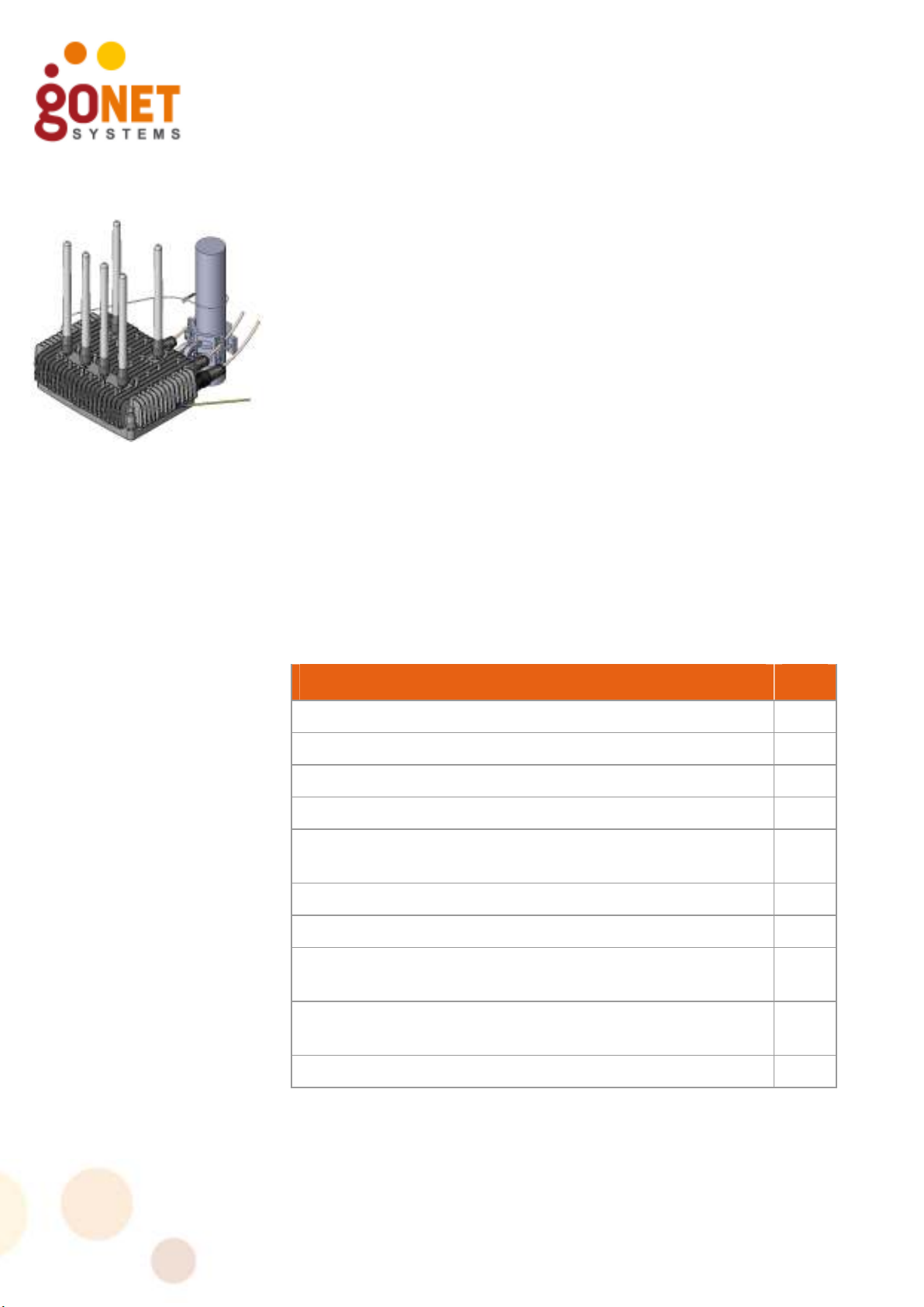
GoBeam 5100
The GoBeam 5100 delivers street-level coverage and provides
capacity enhancements in dense metro areas over an 802.11b/g/n
channel, while meshing traffic over an 802.11a/n radio.
The GoBeam 5100 delivers Omni-directional (360o) coverage
while retaining full xRF smart antenna engine functionality for
enhanced capacity and range.
GoBeam 5100 Features
• Robust IP67 rated weather-proof extended Wi-Fi solution.
• Separate access & backhaul radios delivering unmatched
bandwidth.
• xRF™ smart antenna engine for unmatched (360o) coverage
and capacity enhancements.
• Optional advanced automatic mesh.
• Designed for streetlight, wall, or pole deployment.
• Support for all standard security schemes.
GoBeam 5100 Package Components
Table 2. GoBeam 5100 Package Contents
DESCRIPTION QTY
Included
GoBeam 5100 unit 1
Wall/Poll Mount Kit Assembly 1
Connectors Kit 1
GoBeam 5100 Access Antenna 2.4GHz 7.4dBi Gain,
Omni (P/N: MBW-ANT-2407S)
Antenna Support Plate 1
Optional
802.11a/n 5Ghz 10dBi Omni Mesh Antenna P/N: MBWANT-5810 (5.8Ghz) or P/N: MBW-ANT-5410 (5.4Ghz)
802.11a/n 4.9Ghz 8.5dBi Omni Mesh Antenna P/N: MBWANT-4910 (For model GoBeam 5100J (4.9) only)
Power Injector with power cable 1
4
2
2
2 GoBeam 5100/6100 Installation Guide
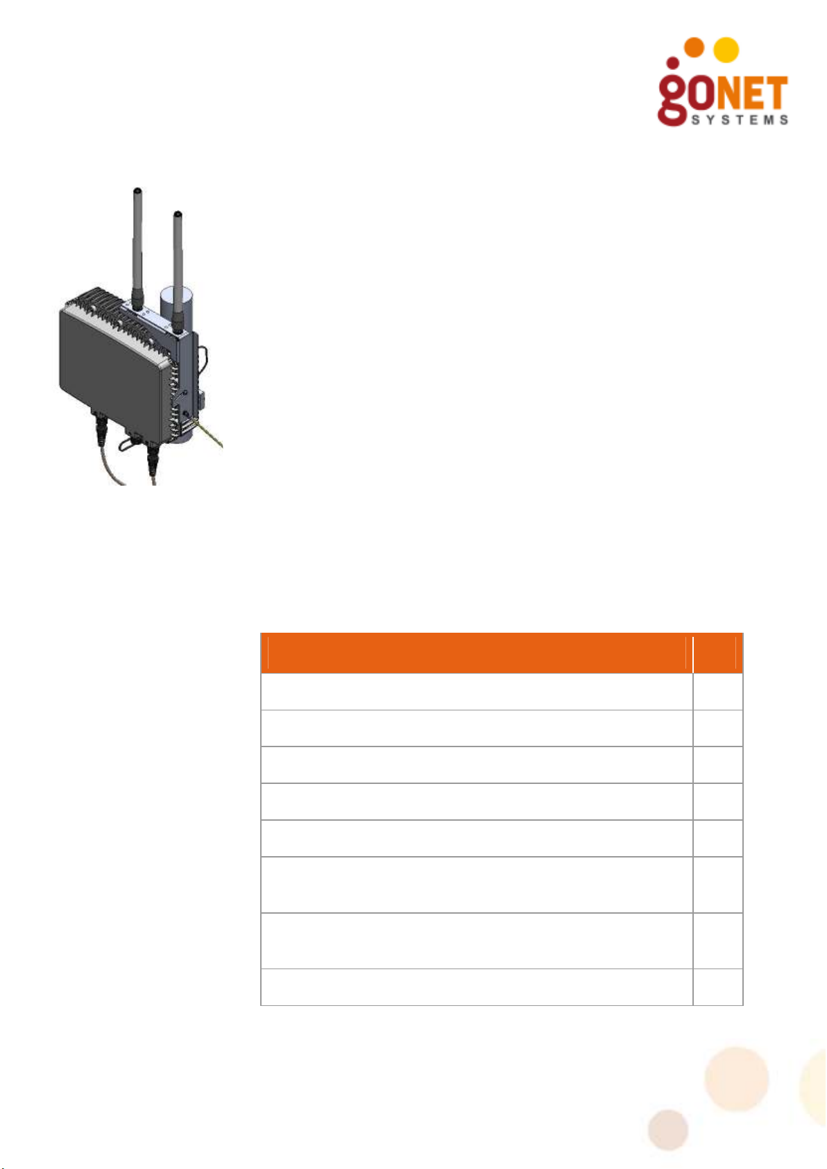
GoBeam 6100
The GoBeam 6100 is designed for mounting on cellular towers,
roof-tops and poles. The GoBeam 6100 complements the GoBeam
5100. The GoBeam 6100 is equipped with one xRF™-powered
beam forming 802.11b/g/n radio for high-performance access and
coverage.
The GoBeam 6100 delivers sector access (120o) coverage while
retaining full xRF smart antenna engine functionality for enhanced
capacity and range.
GoBeam 6100 Features
• Robust IP67 rated weather-proof extended Wi-Fi solution.
• Separate access & backhaul radios delivering unmatched
bandwidth.
• xRF™ smart antenna engine for unmatched (120o) coverage
and capacity enhancements.
• Optional advanced automatic mesh.
• Designed for mounting on cellular towers, roof-tops and poles.
• Support for all standard security schemes.
GoBeam 6100 Package Components
Table 3. GoBeam 6100 Package Contents
DESCRIPTION QTY
Included
GoBeam 6100 unit 1
Wall/Pole Mount Kit Assembly 1
Connectors Kit 1
Optional
802.11a/n 5Ghz 10dBi Omni Mesh Antenna P/N: MBWANT-5810 (5.8Ghz) or P/N: MBW-ANT-5410 (5.4Ghz)
802.11a/n 4.9Ghz 8.5dBi Omni Mesh Antenna P/N: MBWANT-4910 (For model GoBeam 6100J (4.9) only)
Power Injector with power cable 1
2
2
GoBeam 5100/6100 Installation Guide 3

GoBeam 5100/6100 Safety Information
RF Exposure
This equipment complies with the FCC RF radiation exposure
limits set forth for an uncontrolled environment. This
equipment should be installed and operated with a minimum
distance of 20cm between the radiator and any part of your
body.
The antenna(s) used for this transmitter must be fixed-
mounted on indoor or outdoor permanent structures with a
separation distance indoor network device.
The antennas used have an N-Type connector in compliance
with FCC 15.203 Antenna Requirement.
The purpose of the lightning protection is to protect people and
equipment located indoors from lightning that might strike the
GoBeam 5100/6100 or its outdoor cables. Therefore, the lightning
protector device should be installed indoors, as close as possible
to the point where the cables enter the building.
The lightning protector can also be installed outdoors, as long as
the cables that go from the lightning protector to the indoors are
well protected from lightning between the box and the building
entrance.
Verify that you have shared grounding. GoNet Systems offers a
lightning protector that can be ordered separately.
Installation Codes
This device must be installed according to the latest version of the
country national electrical codes. For North America, equipment
must be installed in accordance to the applicable requirements in
the US National Electrical Code and the Canadian Electrical Code.
The device must be professionally installed
4 GoBeam 5100/6100 Installation Guide

Information de sécurité pour GoBeam
5100/6100
Exposition aux fréquences RF
Cet équipement est conforme aux limites d'exposition aux
rayonnements RF de la FCC établ ies pour un environnement
non contrôlé. Cet équipement doit être installé et utilisé à
une distance minimale de 20 cm entre le radiateur et une
partie de votre corps.
Paratonnerre pour GoBeam 5100/6100
Un paratonnerre est nécessaire lorsque le point d’accès GoBeam
5100/6100 est installe à l’extérieur et lié à un network intérieur
par un câble Ethernet.
La fonction du paratonnerre est de protéger les personnes et
équipement situés en intérieur des éclairs qui pourraient frapper
le GoBeam 5100/6100 ou son câble extérieur. Par conséquent, le
paratonnerre doit être installé en intérieur le plus près possible du
point où le câble de liaison pénètre le bâtiment.
Le paratonnerre peut aussi être installé en extérieur à la condition
que les câbles a l’intérieur du bâtiment soient protégés des éclairs
entre le point d‘accès et l’entrée du bâtiment
Vérifier que la prise de terre est partagée. GoNet Systems met a
disposition à la vente un paratonnerre.
Codes d'installation
Ce dispositif doit être installé conformément à la dernière version
des codes électriques nationaux du pays concerné. Pour
l'Amérique du Nord, l'équipement doit être installé conformément
aux exigences applicables dans le US National Electrical Code et le
Code canadien de l'électricité.
L'appareil doit être installé par un professionnel
GoBeam 5100/6100 Installation Guide 5

Installation
The installation process for the GoBeam 5100/6100 is described
below. The differences between the GoBeam 5100 and the
GoBeam 6100 installation process are noted.
Specific installation may require different Power/Ethernet
connections. See Cable Connections, page 21 for more details.
Installation Process
Installing the GoBeam 5100/6100 involves the following steps:
1. Performing a Site Survey.
2. Assembling and Mounting.
3. Mounting the GoBeam 5100/6100 unit.
4. Connecting the cables.
5. Powering up the unit and configuring the software.
6. Performing a Post-installation Testing Procedure to verify
connectivity and operation.
Site Survey
Most wireless LANs include many access points installed in various
locations in an overlapping radio-cell pattern. It is important to
carefully identify each access point’s position and the assignment
of its radio channels. Therefore, a site survey becomes an
essential first step before physically deploying the GoBeam
5100/6100.
Installation of the access points requires backhaul. The backhaul
connection can be a mesh configuration, an Ethernet-wired
connection, or a third-party solution. When using any method
other than a wired connection, keep in mind the GoBeam
5100/6100 requires good reception on its backhaul side in order
to avoid limiting the performance of the access-channel.
Conclude the site survey with a detailed plan of the GoBeam
system deployment. The system deployment plan should include
GoBeam 5100/6100 mounting points and the routes for the power
and backhaul cables.
6 GoBeam 5100/6100 Installation Guide

Assembling the GoBeam 5100 Antennas
The GoBeam 5100 supports either four or six antennas.
• Four Wi-Fi antennas used for user access, which operate on
the 2.4 GHz band, marked A1 to A4 (
• Two optional antennas are used for the mesh networking
connections, which operate on the 5 GHz band, marked
B1 and B2.
GoBeam 5100 Wi-Fi antennas
To mount the Wi-Fi antennas on the GoBeam 5100:
1. Attach the four 2.4 GHz band antennas to terminals A1 to
A4 and screw all antennas into place by hand. Rotate each
antenna at its metallic base. The antennas should rotate
easily. Tighten the antenna by hand only. Do not apply
excessive force by using any tool, as this may damage the
unit.
MBW-ANT-2407S)
.
2.4 GHz
Antennas
Figure 1: GoBeam 5100 2.4 GHz Band Antennas Installation
GoBeam 5100/6100 Installation Guide 7
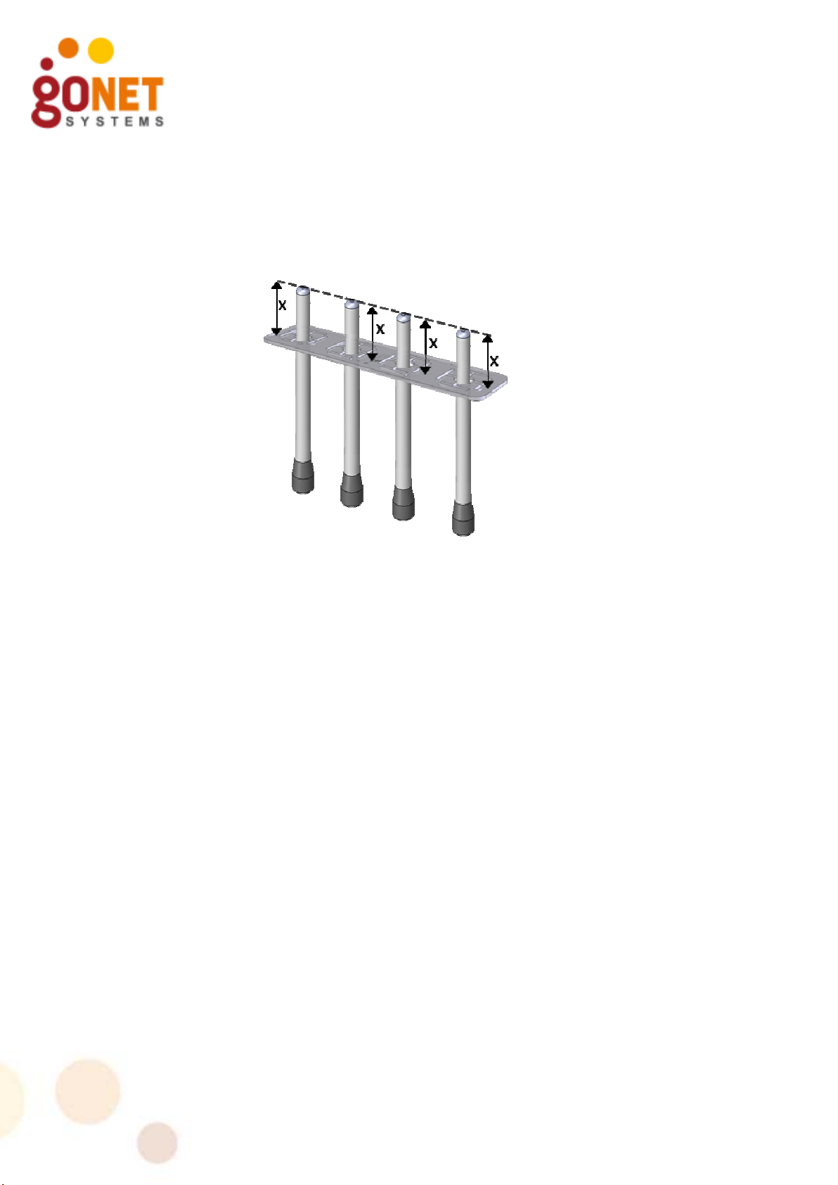
2. Insert the four 2.4 GHz band antennas into the Antenna
Support Plate. The antennas must be inserted evenly, so
that the plate is level and all the antennas are protruding
the same amount. The purpose of the support plate is to
stabilize the antennas and keeps them aligned at all times.
The plate is meant to fit tightly. Use a bit of force if
necessary.
Figure 2: Antenna Support Plate Installation
GoBeam 5100 Mesh antennas
The mesh antennas are optional and assembly is described below
in Attaching Mesh Antennas, page 20.
Assembling and Mounting the GoBeam 5100/6100
The universal mount is used to attach and secure the GoBeam
5100/6100 to a wall, a streetlight arm, or a variety of poles.
The GoBeam 5100/6100 mounting consists of the following stages
and should be performed in the following order:
1. Connect the GoBeam 5100/6100 unit to the brackets using the
‘L’ adaptor.
2. Secure the mounting brackets to a streetlight arm, wall, or
pole.
3. Assemble the GoBeam 5100/6100 unit to the bracket.
4. Ground the GoBeam 5100/6100 unit.
5. Adjust the GoBeam 5100/6100 unit.
6. For pole mounting, install the security cable.
8 GoBeam 5100/6100 Installation Guide

Table 4 lists the universal mount parts. Differences between the
GoBeam 5100/6100 are indicated.
Table 4. Mounting Kit Part List
Item No. Description Qty Picture
A Wall/Pole Bracket 1
B Clamping Bracket 1
C ‘L’ Adapter Wall/Pole
1
Mount
D
‘T’ Adapter Wall/Pole
1
Mount
E Hex Bolt M8x70 2
F Hex Bolt M8x40 1
G Hex Bolt M8x25 1
H Flat Washer M8 4
(6100)
3
(5100)
I Spring Washer M8 4
(6100)
3
(5100)
J Nut M8 1
GoBeam 5100/6100 Installation Guide 9

Item No. Description Qty Picture
K Safety Cable 1
L
Antenna Support Plate 1
10 GoBeam 5100/6100 Installation Guide

Flat Washer
Spring
Washer
Hex Bolt
“L” Adapter
Hardware and Connectors Installation Tools
The following tools are required to mount the GoBeam
5100/6100.
Table 5. Mounting Tools and Equipment
Description Picture
Combination Wrench (7 mm)
7 mm
Combination Wrench (13 mm)
13 mm
Torque Wrench
All hardware and tools used for assembling and mounting the
GoBeam 5100/6100 are Metric.
Mounting Adapters
When mounting to a pole, the required mounting adapter is based
on the position of the pole. Installation to a horizontal pole
requires using the ‘L’ adapter. Installation to a vertical pole
requires using the ‘T’ adapter.
To assemble the ‘L’ adaptor [C] to the GoBeam 5100/6100
unit:
• Attach the ‘L’ adapter to the GoBeam 5100/6100 using an
M8x25 hex bolt [G], a spring washer [I], and a flat washer
[H], as illustrated in Figure 3.
Figure 3. Mount ‘L’ Assembly
GoBeam 5100/6100 Installation Guide 11

Flat Washer
Spring
Washer
Hex Bolt
“T” Adapter
To assemble the ‘T’ adaptor [D] to the GoBeam 6100 unit:
• Attach the ‘T’ adapter to the GoBeam 6100 using an M8x25
hex bolt [G], a spring washer [I], and a flat washer [H], as
illustrated in Figure 4.
Figure 4. Mount ‘T’ Assembly
12 GoBeam 5100/6100 Installation Guide

Mounting Brackets
To secure the mounting brackets:
1. Select an optimal mounting location on the pole or wall.
Select the highest mounting location with minimal
obstacles to the antennas for optimal performance.
When mounting the GoBeam 5100/6100, the pole or wall
mounting must support a minimum of 61.6 lbs (28 kg). In
addition, the pole or wall mounting must support the wind
loads from the GoBeam 5100/6100. For example, the wind
load at a wind velocity of 100 mph (160 km/h) is 24.2 lbs
(11 kg) and the wind load at a wind velocity of 165 mph
(264 km/h) is 66.1 lbs (30 kg).
Lorsque vous montez la GoBeam 5100/6100, le poteau ou le
montage mural doit supporter d'un minimum de 61.6 lbs
(28 kg). En outre, le montage sur le poteau ou sur le mur doit
appuyer les surcharges dues au vent de la GoBeam 5100/6100
(par exemple, 24.2 lbs (11 kg) pour la vitesse du vent de
100 mph (160 km/h), 66.1 lbs (30 kg) pour l'énergie éolienne
Vitesse de 165 mph (264 km/h)).
2. Installation of the mounting brackets to a streetlight arm
or a pole differs according to the diameter of the pole, as
illustrated in Figure 5.
Narrow pole
1"- 1.75"
Normal pole
1.75"-3”
Large pole
larger than 3"
Figure 5. Pole Bracket Assembly
GoBeam 5100/6100 Installation Guide 13

Narrow pole
Wall Mounting Bracket
1"- 1.75"
Normal pole
1.75"- 3"
I
H
E
Large pole
larger than 3"
For narrow poles (1”–1.75” diameter):
1. Place the two brackets, [A] and [B], around the pole at the
approximate height where you wish to place the unit.
When placing the clamping bracket [B], the small notch
H
I
side should be in contact with the pole.
2. Use two M8x70 hex bolts [E] spring washers [I] and flat
washers [H], insert them through both brackets and
tighten them around the pole so that the two brackets are
E
securely fastened.
For normal poles (1.75”–3” diameter):
1. Place the two brackets, [A] and [B], around the pole at the
approximate height where you wish to place the unit.
When placing the clamping bracket [B], the large notch
side should be in contact with the pole.
2. Use two M8x70 hex bolts [E] spring washers [I] and flat
washers [H], insert them through both brackets and
tighten them around the pole so that the two brackets are
securely fastened.
For large poles (larger than 3” in diameter):
1. The wall/pole bracket [A] and two 9/16" (14mm) wide
stainless steel hose clamps (not supplied with mounting
kit) are used. The hose clamps must be the appropriate
size to fit around the pole and bracket.
2. Open the each hose clamp by rotating the screw on the
clamp counterclockwise. There may be additional
resistance just before the clamp is completely open. This is
normal and you should continue rotating the screws until
the clamps are open.
3. Insert the band of each clamp through both slots and over
the bracket [A].
4. Place the bracket [A] and hose clamps around the pole at
the approximate height where you wish to place the unit.
5. Close each clamp by reinserting the band under the screw
and rotate the screw clockwise.
6. Position the bracket in the appropriate location and tighten
the clamps around the pole so that the bracket is securely
fastened.
For wall mounting:
1. Fasten the wall/pole bracket [A] to the wall using four
3/16” (5mm) bolts. Use the appropriate bolts and
fasteners, which is dependent on the material of the wall.
Wall-mounting bolts and fasteners are not supplied with
the mounting kit.
2. Place the wall/pole bracket [A] at the appropriate location
where you wish to place the unit. Using the four holes at
the corners of the bracket, mark the location where the
fasteners need to be installed.
3. Install the four fasteners in the wall.
14 GoBeam 5100/6100 Installation Guide

Nut
4. Insert the four bolts through the bracket and securely
fasten the bracket to the wall.
Mounting the GoBeam 5100/6100 on a horizontal pole
When mounting to a pole, the required mounting adapter is based
on the position of the pole.
Installation on a horizontal pole requires using the ‘L’ adapter.
To mount the GoBeam 5100/6100 unit to a horizontal pole:
1. After assembling the brackets, mount the GoBeam
5100/6100 unit on to the bracket as shown in Figure 6.
Use a flat washer [H], a spring washer [I] and a nut [J].
Spring Washer
Flat Washer
Figure 6. Unit Horizontal Pole Mounting
2. Once the GoBeam 5100/6100 unit is mounted, release the
bolts slightly and adjust the GoBeam 5100/6100 unit to
enhance the coverage and bypass interference. When the
unit is adjusted, firmly close all bolts, applying 120 inch-lbs
of torque.
Mounting the GoBeam 6100 on a vertical pole
Installation on a vertical pole requires the ‘T’ adapter.
To mount the GoBeam 6100 unit on a vertical pole:
1. After assembling the brackets, mount the GoBeam 6100
unit onto the bracket as shown in Figure 6. Use a bolt [F],
flat washer [H], spring washer [I] and nut [J].
GoBeam 5100/6100 Installation Guide 15

Flat Washer
Spring Washer
Nut
Nut
Figure 7. GoBeam 6100 Unit Vertical Pole Mounting
2. Once the GoBeam 6100 unit is mounted, release the bolts
slightly and adjust the GoBeam 6100 unit to enhance the
coverage and bypass interference. When the unit is
adjusted, firmly close all bolts, applying 120 inch-lbs of
torque.
Installing the Safety Cable
Once the GoBeam 5100/6100 unit is mounted, install the safety
cable.
1. Wrap the safety cable around the pole and insert the mounting
plate through the cable loop.
2. Attach the mounting plate to the GoBeam 5100/6100 unit
using the hexagonal bolts, as shown below.
16 GoBeam 5100/6100 Installation Guide
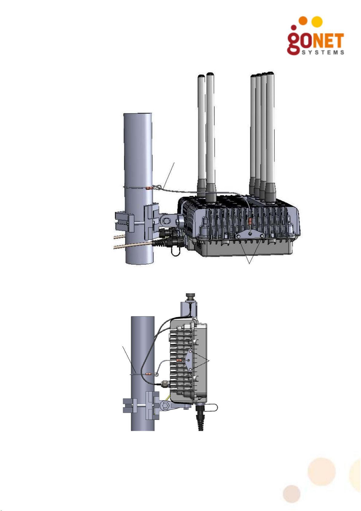
Bolts
Safety Cable
Bolts
Figure 8. GoBeam 5100 Safety Cable Installation
Safety
Cable
Figure 9. GoBeam 6100 Safety Cable Installation
Assembling the Optional Mesh Antennas
GoBeam 5100/6100 Installation Guide 17

Mesh
Antennas
The Mesh Antennas are optional. For the GoBeam 5100, assemble
the mesh antennas at the same time as the other antennas. For
the GoBeam 6100, assembly of the antennas will usually be done
after the L-bracket is mounted on the pole.
Table 6. GoBeam 5100 Mesh Antenna Kit Part List
Mesh
Antennas
Item
No.
A Mesh Antenna 2
Description Qty Picture
The mesh antennas look similar to the access antennas
supplied with the GoBeam 5100. When assembling mesh
antennas, check that you are not using an access antenna
(marked with label MBW-ANT-2407S). Table 2 lists all the
antennas and their model numbers.
Table 7. GoBeam 6100 Mesh Antenna Kit Part List
Item
No.
A Mesh Antenna 2
Description Qty Picture
B Omni Antenna L-
Brackets
C Screw M4 2
D Flat Washer M4 2
E Spring Washer M4 2
F Antenna Cable 2
18 GoBeam 5100/6100 Installation Guide
1

Installation Tools
The following tools are required to mount the mesh antenna on a
pole.
Table 8. Antenna Mounting Tools
Description Picture
Combination Wrench (18 mm)
18 mm
Torque Wrench
Attaching Antenna Cables to L-Bracket
1. Select an optimal mounting location on the pole. Select the
highest mounting location with minimal obstacles to the
antennas for optimal performance.
2. Attach each antenna cable [F] to the L-bracket [B], as
illustrated in Figure 10.
a) Remove the nut and lock washer from the antenna
connector.
b) Insert the connector through the hole in the bracket.
c) Reassemble the lock washer and nut to the connector.
d) Tighten the nut to 45 inch-lbs of torque.
Figure 10. Attaching Antenna Cables to L-Bracket
GoBeam 5100/6100 Installation Guide 19

Mounting the L-Bracket to the Chassis
Mount the L-bracket to the unit as illustrated in Figure 11.
1. Attach the L-bracket to the chassis as shown. Before screwing
the bracket tight, tilt it so that it is vertical. The Mesh antennas
must be mounted vertically in respect to the ground.
2. Attach the other ends of the antenna cable [F] to terminals B1
& B2 on the GoBeam 6100 unit. Tighten the connector by hand.
Do not apply excessive force by using any tool, as this may
damage the unit.
Figure 11. Mounting L-Bracket and attaching Antenna Wires
Attaching Mesh Antennas
Attach each mesh antenna to the unit as follows:
1. Screw the antenna into place by hand by rotating the
antenna at its metallic base. The antenna should rotate
easily.
2. Tighten the antenna by hand only. Do not apply excessive
force by using any tool, as this may damage the antenna
and connector.
20 GoBeam 5100/6100 Installation Guide

Antennas
Mesh
Antennas
GoBeam 5100 GoBeam 6100
Mesh
Figure 12. Attaching Mesh Antennas
Cable Connections
When the GoBeam 5100/6100 is properly adjusted, the
connecters are located at the bottom of the unit.
Cable requirements are often unique to the location and
deployment topology of each installation. As a result of this
limitation, the Ethernet and grounding cables are not included in
the installation kit.
The following cables are required to install the GoBeam
5100/6100 unit and should be connected in the following order:
• Grounding Cable – Provides the necessary electrical safety
functions.
• Power over Ethernet (PoE) Cable – Supplies 48 VDC power
to the GoBeam 5100/6100 unit and a 10/100 Ethernet
connection to a wired network.
• RS-232/RJ45 Console Cable – Provides a connection from
the GoBeam 5100/6100 unit to a console (laptop computer)
for configuration. This cable is not provided with the GoBeam
5100/6100 unit.
It is recommended that the GoBeam 5100/6100 be pre-
configured prior to installation.
GoBeam 5100/6100 Installation Guide 21

Table 9 lists the GoBeam 5100/6100 Connectors Kit parts:
Table 9. Connectors Kit Part List
Item
No.
A Ring
B Ground
Description Qty Picture
1
Terminal
1
Screw
C Lock Washer 2
D Waterproof
2
RJ45
connector
Cable Installation Tools
The following special tools are required to install and connect
cables related to the GoBeam 5100/6100.
Table 10. Cable Installation Tools and Equipment
Description Picture
#2 Phillips Screwdriver
RJ45 Crimp Tool
HT-210A
22 GoBeam 5100/6100 Installation Guide

Grounding Cable
Connect a grounding wire to the grounding screw at the side of
the GoBeam 5100/6100 unit, near the grounding icon. A 10 AWG
grounding cable is required to ground the GoBeam 5100/6100
unit.
GoBeam 5100 GoBeam 6100
Figure 13. Grounding Connection
To ground the GoBeam 5100/6100 unit:
1. Crimp the ring terminal [A] contained in the GoBeam
5100/6100 Connectors Kit to the grounding cable.
2. Attach the solder-less ring terminal [A] to the side of the
GoBeam 5100/6100 unit using the grounding screw [B]
and lock washers [C].
3. Connect the other end of the grounding cable to a proper
ground adhering to local and national electrical codes.
Connect the 10 AWG grounding cable before connecting any
other cables. When removing the GoBeam 5100/6100, the
grounding cable should be the last cable removed.
Connecter la prise de terre 10 AWG avant de connecter tout
autre câble. Pendant la désinstallation du GoBeam 5100/6100,
la prise de terre doit être le dernier câble retiré.
GoBeam 5100/6100 Installation Guide 23

Power over Ethernet (PoE) Connection
The Power over Ethernet (PoE) connection supplies the GoBeam
5100/6100 unit with power and includes an Ethernet connection.
This connection is used for wired backhaul connection or an
interface to a third party wireless backhaul solution. Use outdoor
rated CAT5 shielded cables or better. The outer diameter of the
Ethernet cable must be 4.8 – 7 mm.
When using CAT5 shielded 24 AWG cables, the cable can be up to
60 meters. When using CAT5 shielded 22 AWG cables, the cable
can be up to 100 meters.
The following diagram illustrates how the PoE cable should be
assembled prior to connecting it to the GoBeam 5100/6100 unit:
Figure 14. Ethernet Cable Connector
Table 11. PoE 10/100 Ethernet Cable Connector and Pinout
Pin # Signal
1 Data
2 Data
3 Data
4 48V (+)
5 48V (+)
6 Data
7 48V (-)
8 48V (-)
The unit requires a PoE power injector.
To wire the PoE connection:
1. Build the PoE cable as described above.
2. Using the PoE cable, connect the RJ45 connector to the
PoE port on the GoBeam 5100/6100. Then assemble and
24 GoBeam 5100/6100 Installation Guide

tighten the sealed RJ45 connector to the GoBeam
5100/6100 unit.
3. Connect the other end of the PoE cable to the Radio port
on the power injector.
4. For Ethernet 10/100 connect the Ethernet cable from the
Ethernet network to the Ethernet port on the power
injector. For 1G, use the Eth 1000 port as shown in
Figure 16.
5. Connect the AC power to the power injector.
The following diagrams illustrate the wiring from the power
injector to the GoBeam 5100/6100 unit.
120/220
Power
Injector
Ethernet
Network
10/100
Figure 15. Ethernet 10/100 Mbps Connection
Ethernet Port
Outdoor Rated CAT5 Shielded
Sealed RJ45
PoE Port
When using 1Gbps Network connection, use the Eth 1000 port as
shown in Figure 16.
120/220
Power
Injector
Figure 16. Ethernet 1Gbps Connection
Outdoor Rated CAT5 Shielded
Sealed RJ45
1G Network Cable
PoE Port
Eth 1000
GoBeam 5100/6100 Installation Guide 25

Console Port: RS232
Table 12. 1Gbps Network Cable Connector and Pinout
Pin # Signal Color
1 BI_DA+ white and green
2 BI_DA- green
3 BI_DB+ white and orange
4 BI_DC+ blue
5 BI_DC- white and blue
6 BI_DB- orange
7 BI_DD+ white and brown
8 BI_DD- brown
Serial Connection
Figure 17 illustrates the CLI cable connections used to connect the
GoBeam 5100/6100 to a notebook computer. This connection is
typically used for the initial configuration. For more information
regarding the configuration, see the GoBeam CLI Configuration
Guide. For more information regarding the RS232 on RJ45 cable,
see Wiring Specifications.
Console Port:
Figure 17. Connect and Access the GoBeam 5100/6100
26 GoBeam 5100/6100 Installation Guide

To initialize the GoBeam 5100/6100 via an RS-232 serial
connection:
• Connect the cable and open a Terminal session. Set the
following parameters in the terminal:
Table 13. Terminal Session Parameters
Parameter System Requirement
Data Bits 8
Baud Rate: 115200
Stop Bits 1
Parity none
Some laptops may not have an RS-232 serial port. If a serial
port is not available, you may use a USB to serial converter.
Power Up and Software Configuration
Since the GoBeam 5100/6100 unit is normally mounted in
places that make it inconvenient to configure after mounting, it
is recommended that wireless communication be established
with the unit prior to installation, so that the unit can later be
configured and monitored from the ground.
To verify communications when installing the GoBeam 5100/6100
unit, the Mesh-Gateways must be installed and powered up first.
The LEDs on the GoBeam 5100/6100 unit indicate the status of
communications between the GoBeam 5100/6100 unit and the
network. See Table 14 for more information on the LED indicators.
The ACT LED on the Mesh-Gateway should be checked to verify
that wired communications have been established. The BH1 LED
on the Mesh-Gateway should be checked to verify that wireless
communications have been established.
When powering up a Mesh-Node, the BH1 LED should be lit to
verify that the GoBeam 5100/6100 unit’s wireless communication
is connected. The BH1 LED indicator will light up after the boot is
completed.
GoBeam 5100/6100 Installation Guide 27

Table 14. LED Indicators
LED Function
PWR Green
There is power to the unit.
–
Unlit – There is no power to the unit.
STA Green – The operational status of the GoBeam
5100/6100 unit is normal.
Red – The GoBeam 5100/6100 unit is in a failure state.
Unlit – There is no power to the unit.
ACT Green – When the LED is on, there is a communication
connection. When the LED is flashing, traffic is
flowing though the GoBeam 5100/6100 unit.
Unlit – There is no communication connection.
BH1 Green – On a Mesh-Gateway, the mesh functionality is
activated.
Unlit – On a Mesh-Node, the GoBeam 5100/6100 is
connected to the mesh.
On a Mesh-Gateway, the mesh functionality is
not activated or no Ethernet link is available.
On a Mesh-Node, the GoBeam 5100/6100 is not
configured or failed to connect to the mesh.
Terminology
Table 15. Terminology
Acronym Explanation
802.11 A family of specifications related to wireless
networking, including: 802.11a/n, 802.11b,
802.11g and 802.11n.
AP Access Point. The hub of a wireless network.
Wireless clients connect to the access point, and
traffic between two clients must travel through the
access point.
28 GoBeam 5100/6100 Installation Guide

Wiring Specifications
Table 16. Console Port Signaling & Cabling with DB-9 Adapter
Console Port
(DTE)
Signal RJ45 Pin RJ45 Pin RJ45
No
RJ45 - RJ45
Straight Cable
RJ-45 to DB-9
Terminal Adapter
DB-9
Pin
Pin
Console
Device
Signal
1 1 1 8 CTS
connection
No
2 2 2 6 DSR
connection
No
3 3 3 5 GND
connection
GND 4 4 4 5 GND
RxD 5 5 5 3 TxD
TxD 6 6 6 2 RxD
No
connection
No
connection
7 7 7 4 DTR
8 8 8 7 RTS
GoBeam 5100/6100 Installation Guide 29
 Loading...