

Page 1

USER’S
MANUAL
Industrial LCD Monitor
Model: GBS-8229
GONBES Technology Co.,Ltd
OCT
2012
User’s Manual 0
Page 2
Copyright
Notice
and
Disclaimer
All rights reserved. No parts of this manual may be reproduced in any form without the express written permission
of GONBES Technology Co., Ltd (GONBES) makes no representations or warranties with respect to the contents
hereof. In addition, information contained herein is subject to change without notice. Every precaution has been
taken in the preparation of this manual. Nevertheless, GONBES assumes no responsibility for errors or
omissions or any damages resulting from the use of the information contained in this publication.
Gonbes is the trademark of GONBES Technology Co., Ltd.
All other trademarks belong to their respective owners.
1. Important Info
Before start this product, please read the User’s Manual carefully, it contains all product-related warnings and important issues.
Do not try the followings:
- unauthorized repairs or parts replacement or other operations
- inappropriate placement including but not limited to lightning, fire, exposure to rain, water, or gas
- switch to the power not in the voltage allowable range
- remove the modified label or the warranty label
Cautions:
WARNING
WIZARD GAME
DO NOT
UNCOVER
To avoid electric shock, do not uncover the metal case,
unauthorized repairs or parts replacement or other
operations are prohibited. Please return to factory for
repair.
2. Introduction
Gonbes Technology Co., Ltd (Gonbes) is the leading manufacturer of video converters such as game converters and
CNC monitor converters. According to the professional experience in the replacing & repairing industrial equipment and the
important feedback from customers on the old converter GBS-8218, we launched an innovative industrial video converter
GBS-8219 after years of developing and testing.
GBS-8219 achieves full automatic conversion from industrial video signal MDA / CGA / EGA / RGB…to standard VGA. It
also brings tangible benefit and convenience to our customers in terms of repairing & replacing industrial monitor. In order to
provide more convenient operation, here we are glad to introduce our new launched GBS-8219 & Industrial monitor all-in-one
model GBS-8229.
User’s Manual 1
Page 3
3. Feature specifications
Signals
MDA、CGA、EGA、RGB、RGB Sog、RGBS、RGBHV、YPbPr
Interface
9pin、3pin、6pin、14pin、20pin、25pin
Input
Horizontal
Frequency
Rate(H)
12kHz to 40kHz
automatically recognized
Supports
15pin VGA,Resolution:800*600/60HZ
or custom-resolution
Output
Interface
D-Sub 15 PIN standard VGA port
Power
DC 12V 1.0A
Note:
1. YPbPr = YUV
2. Input Horizontal Frequency Rate 12 kHz to 40 kHz automatically recognized.
3. Support RGB and YPbPr
4. Support Interlaced Scanning and Line by Line Scanning.
5. Support Vertical Resolution from line200 to line 600 automatically recognized.
6. Support variable Horizontal Resolution automatically recognized.
7. Support RGBHV (separate sync), RGBS (composite sync), automatically recognized.
8. Output resolution: 800*600/60Hz standard VGA or custom-resolution.
4. Interface Definition:
Item Specs
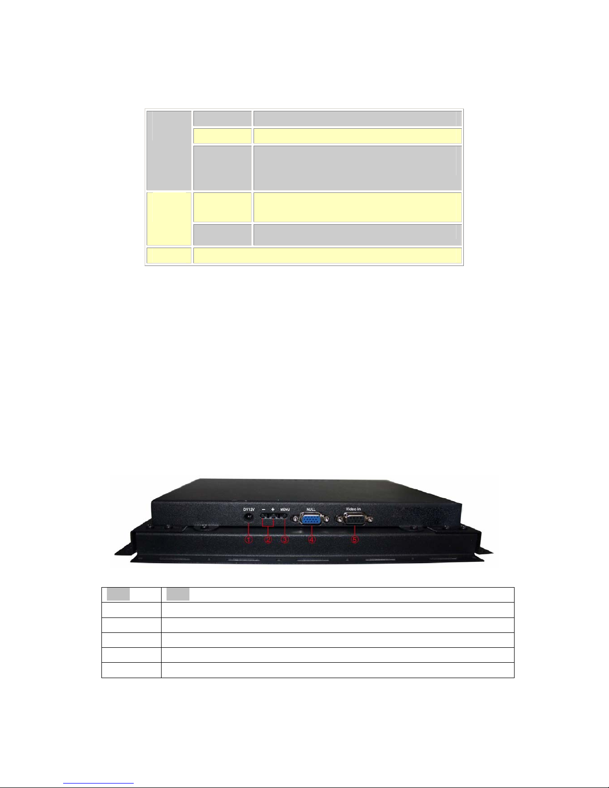
① DC12V
Power input, DC12V, ≥1A
② +、-
Click it to move the cursor up/down, or modify the value
③ MENU
press it to enter into OSD menu; click it once to select and click again to exit the current line
④ NULL
Invalid interface
⑤VIDEO IN
Interface of 9Pin cable, to be connected to the original signal of industrial machines
User’s Manual 2
Page 4
5. Definition for I/O Interface:
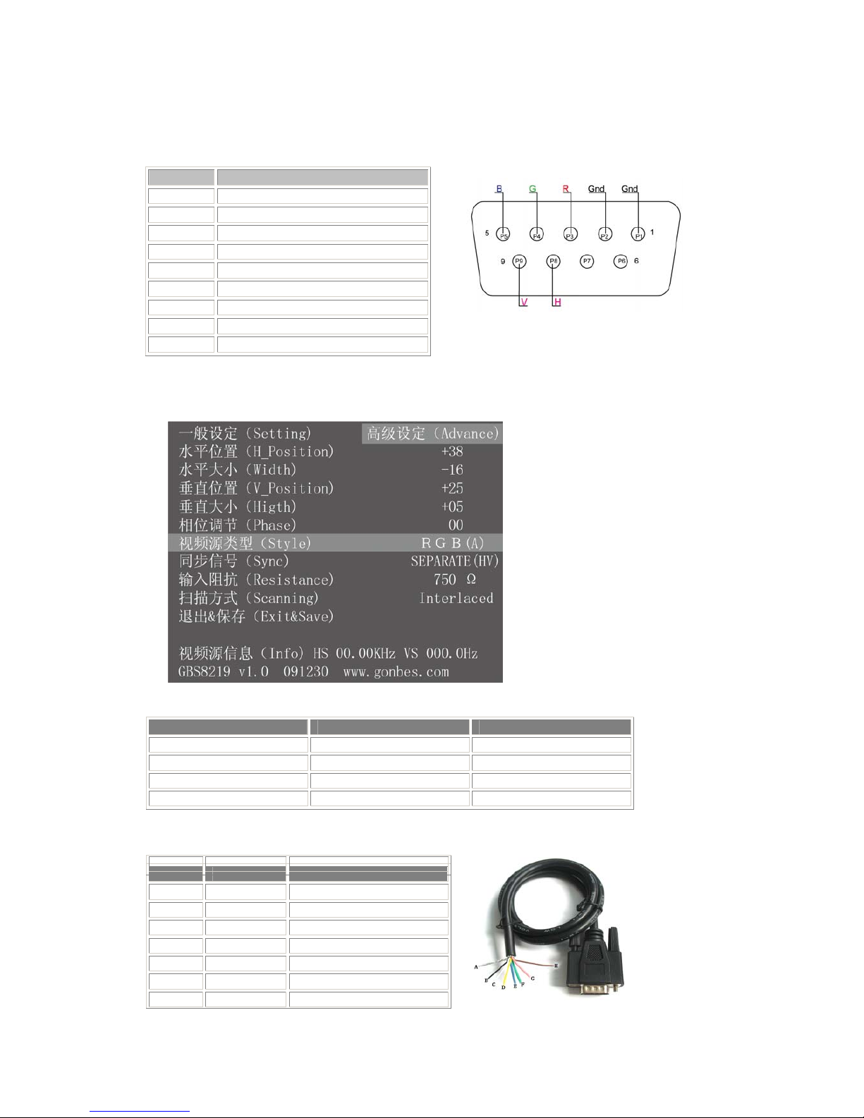
PIN Input Signal
p1(GND) Connect to the ground
p2(GND) Connect to the ground
P3(R) connect R(ed) interface of the input device
P4(G) connect G(reen) interface of the input device
P5(B) connect B(lue) interface of the input device
P6 Undefined(null)
P7 Undefined(null)
P8(H) connect H(CS) interface of the input device
P9(V) connect V interface of the input device
Figure: Definition for Input Channel Ⅱ
6. Operation Menu
7. Accessories& Details
Item QTY Remarks
User’s Manual 1 English
Power Adaptor 1 DC12V,1A
half 9pin cable 1
9pin M-F Connector 2 1 Male + 1 Female
Definition of 9 Pin cable
Name Wire color Signal
A Silver web Shield
B Black wire Ground(GND)
C White wire Vertical Frequency Rate(V)
D Orange wire Horizontal Frequency Rate(H)
E Blue wire Blue(B)
F Green wire Green(G)
G Red wire Red(R)
H Brown wire Undefined(null)
9 pin cable
User’s Manual 3
Page 5
8. Assembly and debugging
Step 1: access signals, if not display or display color is not correct, adjust the video source type items,
adjusted to the input video signal with the same type, color, only the normal display. (Available options
are: YUV color, RGB (D) digital TTL signals, RGB (A) mode may signal)
Step 2: The system can automatically identify the signal. If you adjust the first step, the image color
display is no need to manually adjust the normal; if there distortions in the image, you need to manually
adjust the synchronization signal and the signal source to adjust to the same types of synchronization,
you can normally display.
Step 3: If the screen shows elongated, and the overflow to the bottom of the screen, put the adjusted
scanning: Progressive Scan (Progressive); if the adjustment of the vertical position to a maximum, the
image display is still only half of the display, put the adjust the scanning mode: interlaced scan
(Interlaced).
Step 4: Adjust the horizontal position, horizontal size, vertical position, vertical size of the items, adjusted
to the satisfaction of the location.
Step 5: input impedance, select the input source impedance than with select 750 in Europe, relatively
light, if you choose all 750 European white side, you should choose for the 75 euro.
Step 6: the phase adjustment, if the image appears small waves up and down type jitter, can adjust the
consistency with the input signal phase.
Step 7: Save and Exit: Save all the parameters and exit the menu.
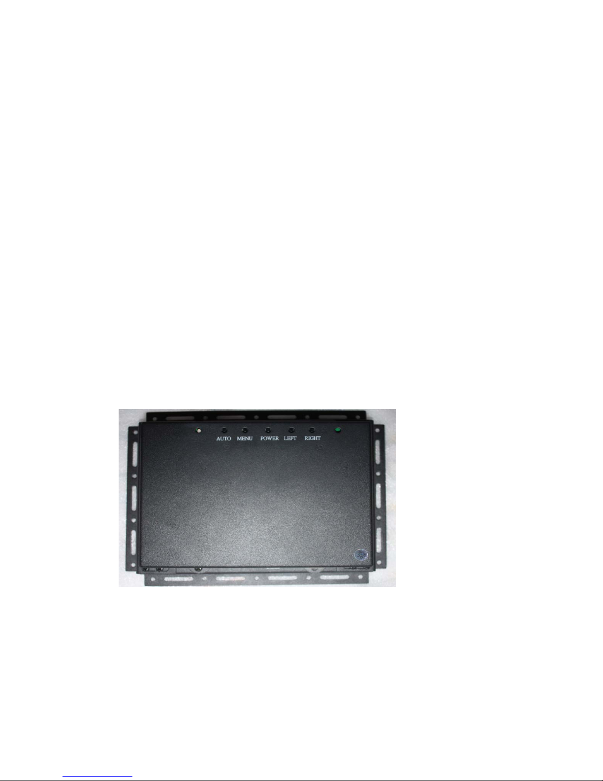
9. Definitions of the back buttons
AUTO: Automatically adjust the screen display.
MENU: Brightness, Contrast, Color, Image position, OSD tools
POWER: Power button to turn on/off the monitor.
LEFT: Move left
RIGHT: Move right
User’s Manual 4
Page 6
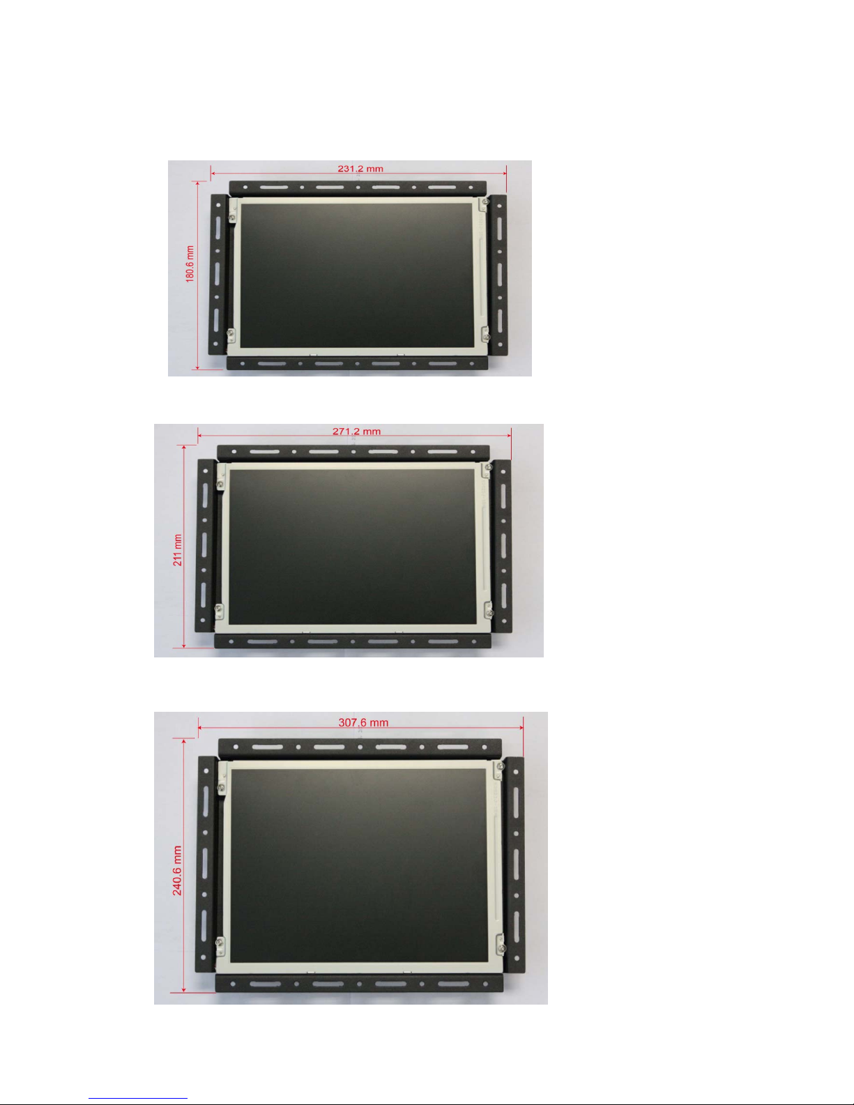
Dimension of 8.4”LCD Monitor (231.2X180.6X60mm)
Dimension of 10.4”LCD Monitor(271.2X211X45mm)
Dimension of 12.1”LCD Monitor(307.6X240.6X45mm)
User’s Manual 5
 Loading...