

INDEX
to
GENERAL INFORMATiON
2.0 SPECIFICATIONS
3.0 SET-UP
4.0 OPERATING PROCEDURE
5.0 OPERATING PRINCIPLE
6.0 MAINTENANCE AND SERVICE
7.0 ILLUSTRATIONS
8.0
TROUBLESHOOTING
9.0 REPLACEMENT PARTS
LIST
1.0 GENERAL
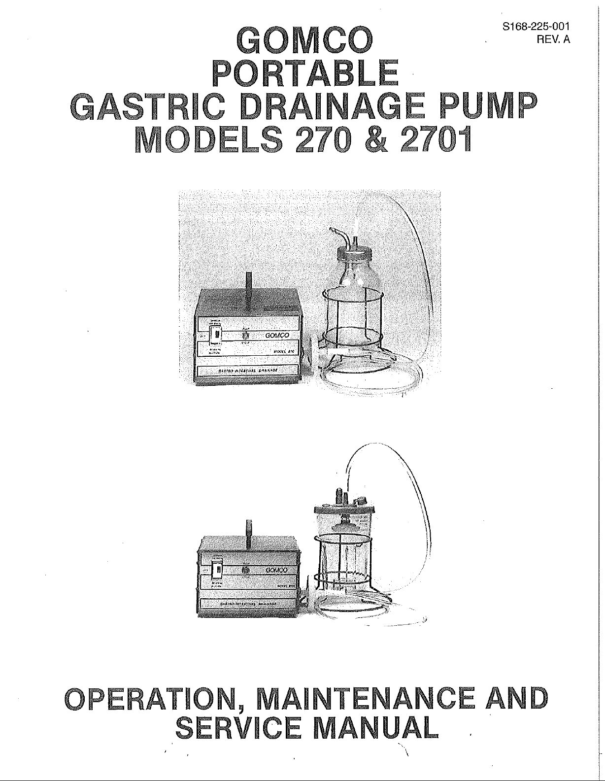
1.1 Purpose:
Gomco
suction for specialized
and fistula drainage following prostatectomy. The suction system includes two preset
drainage levels of 90mm and 120mm of mercury vacuum.
1.2
Features — Model
Supplied
1. One (1) 1200 ml glass collection container
2.
One (1) wire formed
3.
Bacteria
4.
One disposable tubing
5.
Compact
1.2.1
Overflow
INFORMATION:
Models 270 and 2701 are portable drainage pumps designed to assure gentle
uses
as gastric lavage, abdominal decompression, doudenal
270:
with
model 270 as standard equipment are:
with
overflow protection cap
assembly.
bottle
filter
to prevent fluid and aerosol contamination.
PVC
tubing.
case
with
lighted selector switch, pump cycle
plug.
Protection:
The 1200 ml coiiection
and
float
assembly (See
predetermined
cap
and float.
level,
the vacuum supply to the collection
holder.
pacltage
bottle
assembly supplied
Illustration
containing 2-six
No. 4). When collected patient fluids reach a
foot
iengths of clear flexible
light
and hospital grade
with
this pump includes a cap
bottle
is shut off by the
1.2.2
Bacteria
The high efficiency bacteria
aerosoi
hydrophobic, microporous membrane which filters air
(0.3 micron particles in air), while
aerosoi
pump contamination in the
overflow from reaching the pump.
1.3
Features — iViodel
Supplied
1. One 1100 ml disposable collection container
2.
One wire formed container holder.
3.
Bacteria
4.
One disposable tubing
5.
Compact
1.3.1
with
PVC
tubing.
plug.
Overfiow
The 1100 ml disposable collection container supplied
multi-stage
(acts as overflow protection), (2) giass prefilter allows
laser/electrocautery
Fiiter:
filter
is custom engineered to prevent fluid and
contamination of portable suction
blocl^ing
contaminants. The Gomco high efficiency
case
of canister overflow as it helps prevent the
2701:
modei 2701 as standard equipment are:
filter.
case
with
lighted selector switch, pump cycle
protection:
filter
(1) hydrophobic membrane stops flow of aqueous solutions
applications.
paci<age
containing 2-six
units.
the
floW
with
This
filter
features a
with
maximum efficiency
of aqueous fluids and
fiiter
protects against suction
overflow protection cap.
foot
lengths of clear flexible
light
and hospita! grade
with
this pump includes a
filter
to handle most
1.3.2
Bacteria
Fiiter:
The high efficiency bacteria
aerosol
hydrophobic, microporous membrane which filters air
(0.3 micron particles in air), while
aerosol
pump contamination in the
overfiov\(
contamination of portable suction units. This
contaminants. The Gomco high efficiency
from reaching the pump.
filter
is custom engineered to prevent fluid and
bloci^ing
case
of canister overflow as it helps prevent the
'"\
the flow of aqueous
filter
filter
features a
with
maximum efficiency
flujds
protects against suction
and
2.0 SPECIFICATIONS:
2.1 Vacuum:
* At 90mm setting: 90mm to 99mm Hg.
at 120mm setting: 120mm to 132mm Hg.
2.2
Flow
Rate
(Air):
At 90mm setting: .25 iiters/minute
At 120mm setting: .30 liters/minute
2.3 Electrical
115
volts 50/60 Hz. (1.5 amps max.)
230 volts 50/60 Hz. (1.3 amps max.)
2.4 Pump Cylinder:
155
to 160
2.5 Dimensions:
Case
Only - (D) 8" x (w) 8" x (H) 7"
2.6
2.7
*
NOTE;
Overall
Weight:
Shipping
Net - 10 pounds
Duty:
Continuous
Vacuum should be measured after the pump has been running for 15 minutes to normalize the
pump cylinder temperature.
-(D) 8" x
Requirements:
OHMS
-15
resistance
(V\/)
pounds
11" x (H) 7"
3.0 SET-UP:
3.1 Collection
(See
Illustration No. 4)
1. Check the bottie top edges for nicks. If the bottle top is nicked, it will not
2.
Check
3.
Check
4.
Screw the cover assembly securely onto the bottle, making sure
5.
Place
6. Connect one length of tubing, enclosed in the tubing package, to the bacteria
7. Connect the other length of tubing to the long bent metal tube of the cap
3.2 Collection
1.
Make sure
2.
Place
3.
Place
4.
Connect one length of
5.
Connect't'he
Bottle
seals.
filter
pump".
assembly.
Bottle
to snap lid to bottle.
filter
Assembly — Glass
that
the cap gasket Is properly positioned inside the cover.
that
the float moves freely.
the bottle assembly into the wire form bottle holder.
and to the vertical
Assembly — DCU:
filter
shut-off is in place in under side of lid.
bottle on a
bottle into wire form bottle holder.
and to the vertical
flat
other length of tubing to the elbow
fitting
surface and lay cap assembly on bottle.
tubing.-enclosed
fitting
Bottle:
on the bottle cap and float assembiy marked "to
in the tubing package, to the bacteria
of the cap marked vacuum.
marked
that
Push
"patient".
seal.
the gasket
down on cap
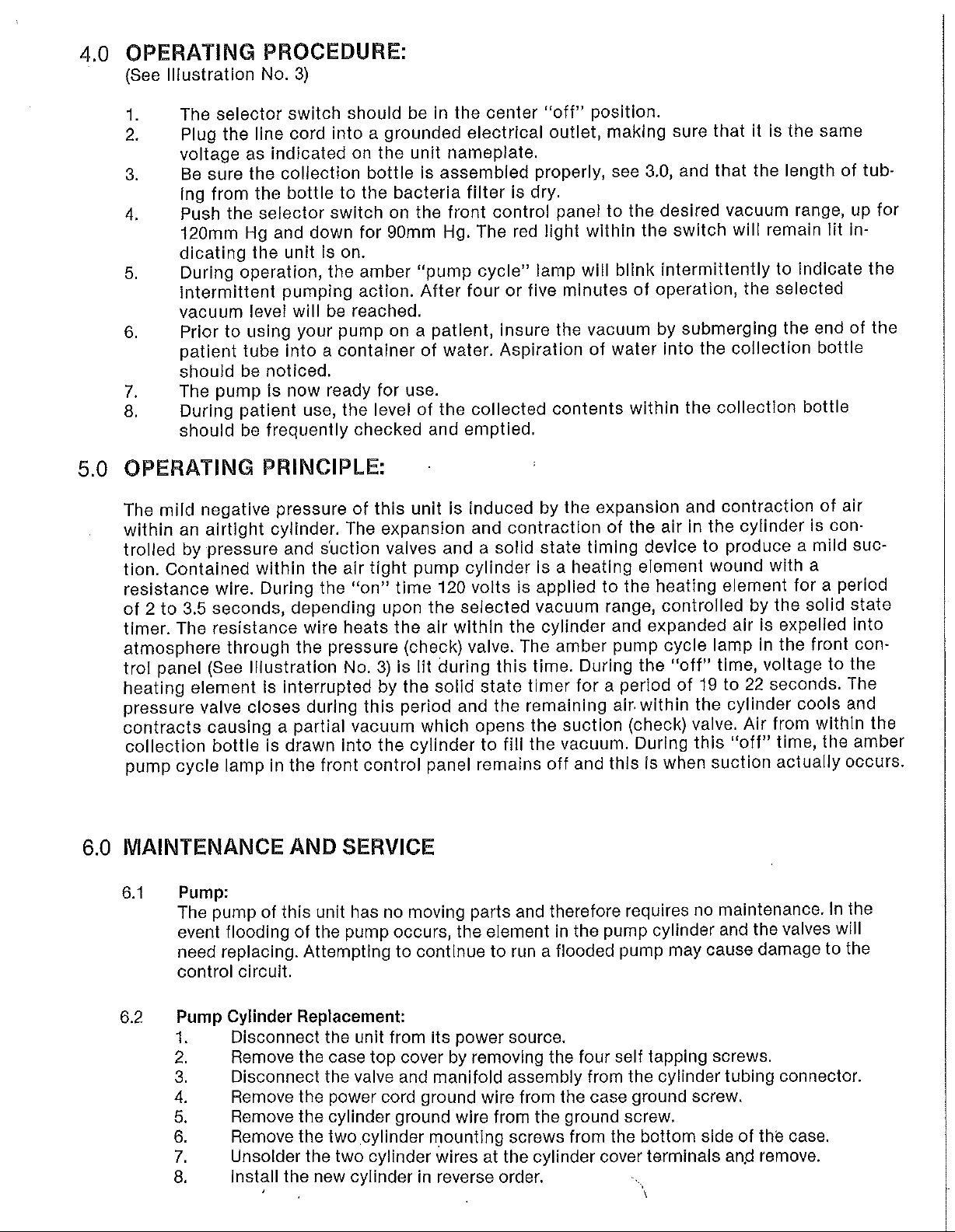
4.0 OPERATING PROCEDURE:
{See Illustration No. 3)
1.
Tiie
2.
Plug
3.
Be sure the collection bottle is assembled properly, see
4.
Push
5.
During operation, the amber "pump
6. Prior to using your pump on a patient, insure the vacuum by submerging the end of the
7. The pump is now ready for use.
8. During patient use, the level of the collected contents within the collection bottle
selector switcli stiouid be in the center "off" position.
the line cord into a grounded electrical outlet, making sure
voltage as indicated on the
ing from the bottle to the bacteria
the selector switch on the
120mm Hg and down for 90mm Hg. The red light within the switch will remain lit in-
dicating the
intermittent
vacuum
patient tube into a container of water. Aspiration of water into the collection bottle
should
should
unit
is on.
pumping action. After four or five minutes of operation, the selected
levei will be reached.
be noticed.
be frequently checked and emptied.
unit
nameplate.
filter
front
3,0,
is dry.
control panel to the desired vacuum range, up for
cycle"
lamp will blink intermittently to indicate the
and
that
it is the same
that
the length of tub-
5.0 OPERATING
The
mild negative pressure of this
within an airtight cylinder. The expansion and contraction of the air in the cylinder is
trolled by pressure and suction valves and a solid state timing device to produce a mild
tion. Contained within the air
resistance
of 2 to 3.5
timer. The resistance wire heats the air within the cylinder and expanded air is expelled into
atmosphere through the pressure (check) valve. The amber pump cycle lamp in the
trol
panel (See Illustration No. 3) is lit during this time. During the "off" time, voltage to the
heating element is interrupted by the solid state timer for a period of 19 to 22
pressure
contracts causing a partial vacuum which opens the suction (check) valve. Air from within the
collection bottle is drawn into the cylinder to
pump cycle lamp in the
6.0
IVIAINTENANCE
6.1 Pump:
valve
The
event flooding of the pump occurs, the element in the pump cylinder and the valves will
need
control circuit.
PRINCIPLE:
unit
is induced by the expansion and contraction of air
tight
pump cylinder is a heating element wound
wire. During the "on" time 120 volts is applied to the heating element for a period
seconds,
depending upon the selected vacuum range, controlled by the solid state
closes
during this period and the remaining air. within the cylinder cools and
fill
the vacuum. During this "off" time, the amber
front
control panel remains off and this is when suction actually occurs.
with
a
front
seconds.
AND SERVICE
pump of this
replacing. Attempting to continue to run a flooded pump may cause damage to the
unit
has no moving parts and therefore requires no maintenance. In the
con-
suc-
con-
The
6.2 Pump Cylinder
1. Disconnect the
2.
Remove the
3.
Disconnect the valve and manifold assembly from the cylinder tubing connector.
4.
Remove the power cord ground wire from the
5.
Remove the cylinder ground wire from the ground screw.
6. Remove the
7. Unsolder the two cylmder wires at the cylinder cover terminals
8.
Install the new cylinder in reverse order.
Replacement:
unit
from Its power source.
case
top cover by removing the four self tapping screws.
two
cylinder mounting screws from the bottom side of the
case
ground screw.
anjd
case.
remove.
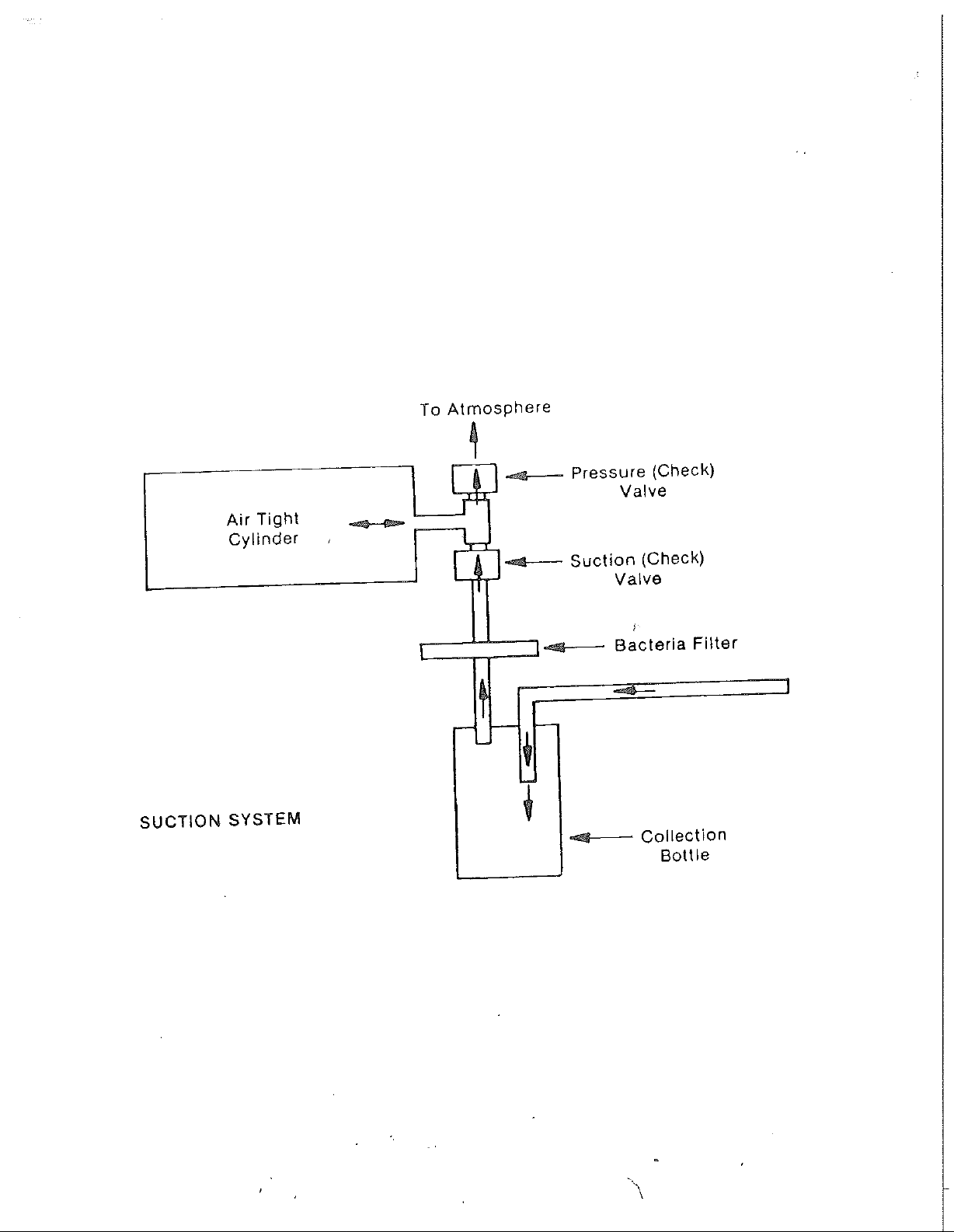
Air
Tight
Cylinder
To Atmosphere
Pressure (Check)
Valve
Suction (Check)
Valve
Bacteria Filter
SUCTION
SYSTEM
Collection
Bottle
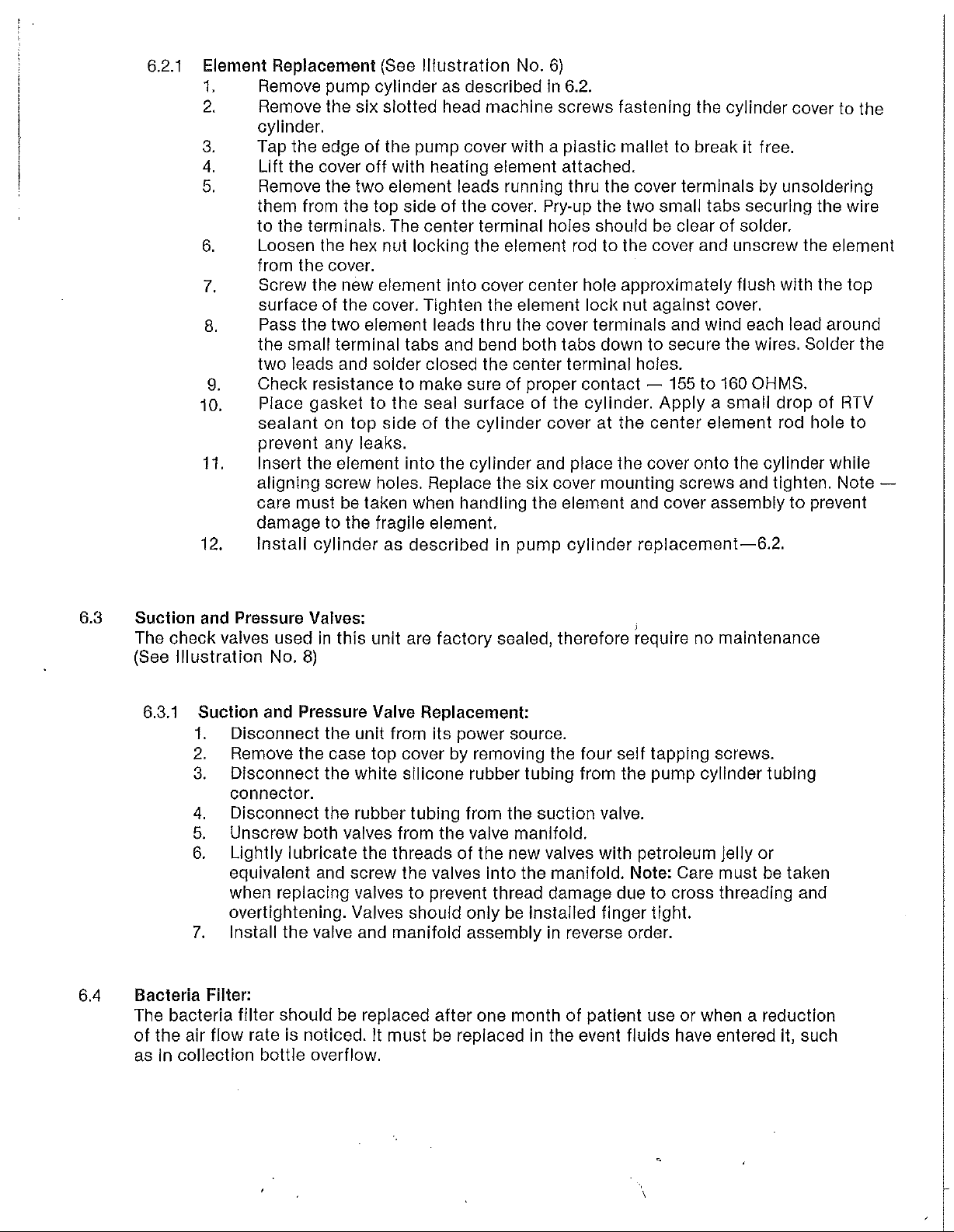
6.2.1
Element
Replacement
1. Remove pump cylinder as described
2.
Remove the six slotted head machine screws fastening the cylinder cover to the
cylinder.
3.
Tap the edge of the pump cover
4.
Lift the cover off
5.
Remove the two eiement leads running
them from the top side of the cover. Pry-up the two small tabs securing the wire
to the terminals. The center terminal holes should be clear of solder.
6. Loosen the hex nut locking the element rod to the cover and unscrew the element
from the cover.
7. Screw the new element into cover center hole approximately flush
surface
8.
Pass
the small terminal tabs and bend both tabs down to secure the wires. Solder the
two leads and solder closed the center terminal holes.
9.
Check resistance to make sure of proper contact — 155 to 160
10.
Piace
sealant
prevent any leaks.
11.
Insert the element into the cylinder and place the cover onto the cylinder while
aligning screw holes. Replace the six cover mounting screws and tighten. Note —
care
damage
12.
Install cylinder as described in pump cylinder
of the cover. Tighten the element lock nut against cover.
the two element leads
gasket to the seal surface of the cylinder. Apply a small drop of RTV
on top side of the cylinder cover at the center element rod hole to
must be taken when handling the element and cover assembly to prevent
to the fragile element.
(See Illustration No. 6)
In
with
a piastic mallet to break it free.
with
heating element attached.
thru
the cover terminals and wind each lead around
6.2.
thru
the cover terminals by unsoldering
with
OHMS.
replacement—6.2.
the top
6.3 Suction and Pressure Valves:
The
check valves used in this
(See
Illustration No. 8)
6.3.1 Suction and Pressure
6.4
Bacteria
The
of the air flow rate is noticed. It must be replaced in the event fluids have entered it, such
as
1. Disconnect the
2.
Remove the
3.
Disconnect the white silicone rubber tubing from the pump cylinder tubing
connector.
4.
Disconnect the rubber tubing from the suction valve.
5.
Unscrew both valves from the valve manifold.
6. Lightly lubricate the threads of the new valves
equivalent and screw the valves into the manifold.
when replacing valves to prevent thread damage due to cross threading and
overtightening. Valves should only be installed finger
7. Install the valve and manifold assembly in reverse order.
Filter:
bacteria
in collection bottle overflow.
filter
should be replaced after one month of patient use or when a reduction
unit
case
unit
are factory
Valve
top cover by removing the four self tapping screws.
Replacement:
from its power source.
sealed,
therefore require no maintenance
with
petroleum jelly or
Note:
Care
tight.
must be taken
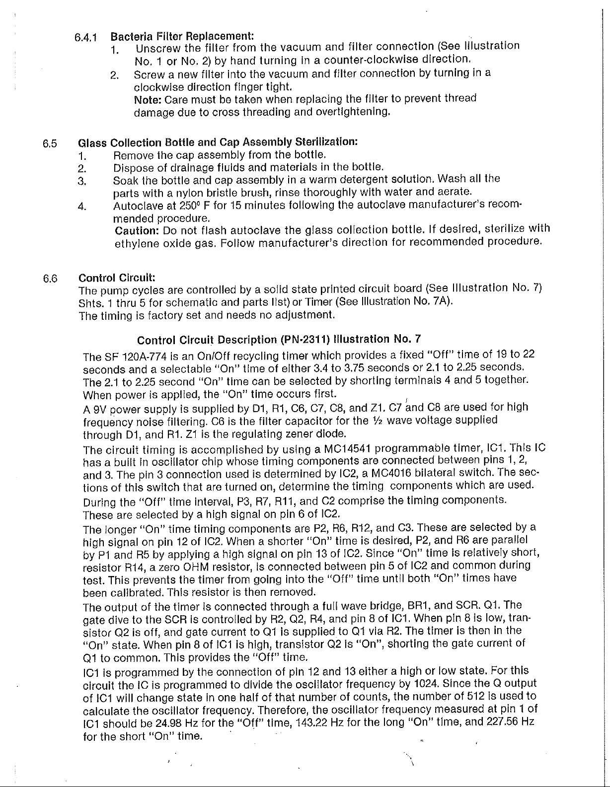
6.4.1
Bacteria
Filler
Repiacement:
1. Unscrew the
No.
1 or No. 2) by hand turning in a
2.
Screw a new
clockwise
Note:
Care
damage due to cross threading and overtightening.
filter
from the vacuum and
counter-cloci<wise
filter
into
the vacuum and
direction finger
must be taken when replacing the
tight.
filter
filter
connection (See
direction.
connection by turning in a
filter
to prevent thread
Illustration
6,5 Glass Collection
1. Remove the cap assembly from the bottle.
2.
Dispose of drainage fluids and materials in the bottle.
3.
4.
6.6
Control
The pump cycles are controlled by a solid state printed circuit board (See
Shts. 1 thru
The timing is factory set and needs no adjustment.
Soak
Autoclave at 250° F for 15 minutes following the autoclave manufacturer's recom-
The SF 120A-774 is an On/Off recycling timer which provides a fixed "Off" time of 19 to 22
seconds
The 2.1 to 2.25 second "On" time can be selected by shorting terminals 4 and 5 together.
When power is applied, the "On" time occurs
A
9V power supply is supplied by
frequency noise filtering. C6 is the
through D1, and
The circuit timing is accomplished by using a MC14541 programmable timer, IC1. This IC
has a built
and 3. The pin 3 connection used is determined by
tions of this switch
During the "Off" time interval, P3, R7,
These
The longer "On" time timing components are P2, R6,
high signal on pin 12 of
by P1 and R5 by applying a high signal on pin 13 of
resistor R14, a zero OHM resistor, is connected between pin 5 of IC2 and common during
test. This prevents the timer from going
been
calibrated. This resistor is then removed.
The
output
gate dive to the SCR is controlled by
sistor Q2 is off. and gate current to
"On"
state. When pin 8 of
Ql
to common. This provides the "Off"
IC1 is programmed by the connection of pin 12 and 13 either a high or low state. For this
circuit the IC is programmed to divide the oscillator frequency by 1024.
of 1C1 will change state in one half of
calculate the oscillator frequency. Therefore, the oscillator frequency measured at pin 1 of
ICI
should be 24.98 Hz for the "Off" time, 143.22 Hz for the long "On"
for
the short "On" time.
the
parts
with
mended procedure.
Caution:
ethylene oxide gas. Follow manufacturer's direction for recommended procedure.
Circuit:
5 for schematic and parts
Control
and a selectable "On" time of either 3.4 to 3.75 seconds or 2.1 to 2.25
in oscillator chip whose timing components are connected between pins 1, 2,
are selected by a high signal on pin 6 of
of the timer
Bottle
bottle
a nylon bristle brush, rinse thoroughly
Do not flash autoclave the glass collection bottle. If desired, sterilize
Rl.
and Cap Assembly
and cap assembly in a warm detergent solution. Wash all the
Circuit
Zl
that
Description
Dl,
filter
is the regulating zener diode.
are turned on, determine the timing components which are
102,
When a shorter "On" time is desired, P2, and R6 are parallel
Is
connected through a
Ql
101
is high, transistor
Steriiization:
with
water and aerate.
Illustration
list)
or Timer (See
(PN-2311)
first.
Rl,
C6, C7,
capacitor for the Vz wave voltage supplied
Rll,
and
into
R2.
Q2, R4, and pin 8 of
is supplied to
time.
that
number of counts, the number of 512 is used to
08,
02
102.
the "Off" time
full
Q2
Illustration
Illustration
and
Zl.
102, a MC4016
comprise the timing components.
R12,
and C3. These are selected by a
102.
Since
until
wave bridge, BR1, and SCR.
01
via R2. The timer is then In the
Is
"On", shorting the gate current of
No, 7A).
No. 7
07
and
08
are used for high
bilateral switch. The
"On" time is relatively short,
both "On" times have
ICI.
When pin 8 is low, tran-
Since
time,
the Q
and 227.56 Hz
No. 7)
seconds.
used.
01.
The
output
with
sec-

6.6.1 Control Circuit Specifications:
1. Mode of operation — continuous On-Off recyciing
input terminals. The load is energized during the "On" time period (See Illustration No. 7).
2.
Input
3.
Time Delays —
4.
Load 160
6,6.2
Control Circuit
1. Disconnect the
2.
Remove the
3.
Disconnect all the wires from the P.C. board by pulling off the
4.
Remove the two P.C. board mounting screws from the bottom side of the
5.
Install the new P.C. board in reverse order. (See Illustration No. 1 for wiring
6. NOTE: On 10/18/04 the P.C. board was replaced
voltage — 120 Volts ± 15%, 50/60 Hz.
OHMS
ON
OFF
terminals (Do not
minal).
case.
detail.)
To
install the encapsulated circuit package, install one mounting screw into an existing
mounting hole In the bottom
package
terminals (See Illustrations No. 2 for wiring detail).
resistive.
AT120
TIME
TIME
Replacement:
unit
from its power source.
case
top cover by removing the four self tapping screws.
pull
on wires.
witti
power appiied to the
AT
MM
SETTING
3.4 to 3.75 sec. 2.1 to 2.25 sec.
19
to
22 sec.
Mal^e
sure you have a
side
of the
case,
90 MM
19
connect all wires to the proper circuit
SETTING
to 22 sec.
firm
hold on the ter-
with
a encapsulated circuit
quicl<
connect
pacl<age.
7.0 ILLUSTRATIONS
No. 1 No.
No.
No.
No.
No. 6 -
No. 7 No.
No.
Final Assembly & Wiring Detail
2 - Final Assembly & Wiring Detail
3 - Front
4 - Collection Bottle Assembly
5 - DCU
Pump Cylinder Assembly
Control Circuit (P.C. BD.)
7A - Control Circuit (Timer)
8 - Valve and Manifold Assembly
Panel
Assembly
w/RC.
w/Tlmer
BD.


ILLUSTRATION
NO. 2


I
a
I
Pi"
\
\
'0
\
\
\
\
\
4^
Vi
Vj
V5
K
\

S>rs
1.
X^ooa
OF
OpHRATiOKJ 1 COMTi'-O^JS
IMpJT
z.
ivipoT
Voi.TA<:ie,
2.2.
SF250A-'>74 = 23o
3.
Ti-ie.
Osi-Art
J 1 OFT
Ti»«e.
3.2 OJ
-r-fl&
5F'2*
ft . pi c AT'o
TEBM
MALS.
rXLAiS
r;c.i-A-<i
A-77-4-
nEVI8<ON$
S
Th£
LOAC
AC
•-
sFizsA-774. : 1^
M'^H
I
<*5
ie<:-.*io%
0>0 - OFF
.-^
i^-^C
.5<i/(-o
T.
J-i
T.
z.zS
-O
i.liec.,*'0%,-0
APP.
fli,
zz
atna-iDs
Sec
BV
ILLUSTRATION NO. 7 SHEET
NO.
1
OWN BY
cpS
CMK.
9Y
DATE:
APP
BY
DATE:
SCALE
fJt-U
00
OATE-
MOT
'?.lC-ao
/a
SCALE
DtUENStONS:
I.OK)
FftACTlONS = -A
2 PLACE
3
PLAC^
AMGLES
IN
IN.
TOlERANCES
S
- UW
=
H«0
D£C. = .01 - .25
DEC. I .005 - ,13
T
MM.
TITLE:
SOL
STATE
PART
PdO:
DWQ- I C?
T...ieC5
?>
4.,

W J o O '
UJ
^
O
i(
K
H H
3 U O
S. .
Ul
UJ
UJ
In Q •
O O
UJ UJ
U.
[M
f)
<
o
ff-
lij
<
•
l/l
'3
>
m
If
r
u
M
o
•J
UJ
<
o
U
>•'
to
0.
fl.
<
N.
CO

01
R I V
PAHT
KO:
REVISIONS
•
APP,
BV
ILLUSTRATION
TC
/
Zi-
—
NO, 7
SHEET
NO. 3
DWN.
CMK.
BY:
APP.
APP.
SCALE;
BY:
SfT.
J-'if'*.
BY:
i{.^4
BY:
i{.^4
r\y 1 DO
DATEi'l'l-^-S-'
DATE:
»0T
<}
•^•If-fx^
•^•If-fx^
SCALE
DWG-
DATE.
DATE.
TOLEPIANCES
FE5ACT10NS = t
2
PLACE
oec. = .01
2
PLACE
oec. = .01
2
PLACE
oec. = .01
3
PLACE
DEC. = .CBK
3
PLACE
DEC. = .CBK
3
PLACE
DEC. = .CBK
ANGLES
=
ANGLES
=
ANGLES
=
T
T
T
TtTLE:e\t;CUiT
PAHT
NO
PAHT
NO
DWG. I OF
DWG. I OF
1
1
B
^

BILL
OF
MATERIALS
REF NO
BRl
Cl
C2
C5
C4
C5
C6
C7,C8
Dl
ICI
IC2
QTY,
1
1
1
1
1
1
1
2
1
•
1
1
BRIDGE
CAPACITOR
CAPACITOR
CAPACITOR
CAPACITOR
CAPACITOR
CAPACITOR
CAPACITOR
RECTIFIER
W04MA
.lufd
.lufd
.Oluf'd
.Olufd
.Olufd
^^uf-d
.00lufd
DIODE
250
250
25
1N4001|
INTEGRATED CIRCUT
INTEGRATED CIRCUT
DESCRIPTION
VDC
VDC
250
VDC
250
VDC
250
VDC
VDC MSR
500
MC
MC
VDC
l45Hl
l40l6
B
B
Pl
P2
P3
Ql
Q2
Rl
R2
R5
r4
R5
r6
R7
r8
1
1
1
1
1
1
1
1
1
1
1
1
1
TRIMPOT
TRIMPOT
TRIMPOT
SCR
TRANSISTOR
RESISTOR
RESISTOR
RESISTOR
RESISTOR
RESISTOR
RESISTOR 270K
RESISTOR 120K
RESISTOR
1 MEG. OHM
lOOK
lOOK
C 106 D
2^15172
22K
lOK
4.7K
27IC
47K
27K
'
OHM
OHM
OHM
1^2
WATT
OHM i WATT
OHM ^ V7ATT
OHM h WATT
OHM ^ WATT
OHM ^ WATT
OHM ^ WATT
OHM i WATT
R9
1
RESISTOR
lOKOHM i WATT
iL|„USTRATiON
NO. 7 SHEET
4

REF
RIO
NO
QTY.
1
BILL
RESISTOR
OF
33K
MATERIALS
DESCRIPTION
OHM i WATT
Rll
R12
R13
Rll|
R15,16,17
1
1
1
I
1
1
5
1
1
3
RESISTOR
RESISTOR
RESISTOR
RESISTOR
RESISTOR
ZENER
PRINTED CIRCUT
i
IN. TERMINAL
COVER
LABEL
SPACER
390K
390K
27K
0 OHM i WATT
0 OHM f WATT
9V
1N5239B
OHM i WATT
OHM i WATT
OHM J WATT
BOARD
ILLUSTRATION
NO. 7 SHEET
5

2.0
2311-1
INPUT
120
3
VAC
2
L_.^
;._J
1
REV.
ITR.
REVISIONS
E.C.O.
NUMBER
DATE
OCP
4i.
F3
BY
-
2.0
1.2
us
07CB13S
MAX.
3
2
(-)
PATENT
1
00.250
THRU
THS
PRINT
IS
AUJEO
ANO
PRODUCED.
POSED
INDIRECTLY. NOR USED FOR ANY
PURPOSE
FOR
FURNISHED EXCEPT BY
PERMISSION OF ALUEO HEALTHCARE
DRAW
PLOTSCALE:-
THE PROPERTY OF
HEALTHCARE PROOUCTS
SH^
NOT BE
COPIED.RE-
LOANED.OR
OF EITHER DIRECTLY OR
OWER
TMAM
iS
SPEOHCALLY
WRITTEN
1:1
THAT
WHICH
IT
PRODUCTS.
SCALE:
1:1
DIS-
0.25 INCH
uMi£ss
onoviiEE
SPEoreo
25/^
«
\J
B*fl.1
SACHINOX
ajRFACi^
SYUBOLS
PER
Y14.5
EDGES
ANSI
ALL SHARP
.0DS/-ai5
.015 R. WAX.
ALL
BURRS
ORAViINC
STO.
BREAK
nU£TS
REUO^
DO NOT SCALE
us
PAIEMT f CPl]
ri!rt=>-
CONNECTIOM
OlACRAM
MALE
PLACE
LABEL
THE
CUSTOMER
TIME
CURRENT
QUICK
LABEL
IS
CONNECT
AS SHOWN
TO BE
MARKED
TERMINALS
WITH
FOLLOWING INFORMATION:
PART
DELAYS.
NUMBER
VOLTAGE
AND
RATING.
wiEES
otMOnKE
DIUEN30HS
ARC
TOLERANCES
ANCL£S±
XL
.1
-XXt
.02
.m«±
.005
niAcnoNSi
T
atortti
IM
INC»[S
ARE:
1/32"
DRAWN
CHECK
DESIGN
APPROVED
APPROVED
CATALOG
iNlllAL
ft£L£ASt;
SIGNATURE
Vl
NO,
AG
NO.
DATE
01 /05
9847
AND DATE
swwot's
OUAUTY
Oft
PRODUCTS.
APPROVAI.
or
4i£,J
4i£,J
4i£,J
/A
ULLvVL
/A
ULLvVL
/A
ULLvVL
««.i>iii™;i«tiuoni-1
««.i>iii™;i«tiuoni-1
««.i>iii™;i«tiuoni-1
TiTLz
ENCAPSULATED
TiTLz
ENCAPSULATED
GOMCO
GOMCO
3IE
g
3IE
g
SCALE
1:1
(5
PLACES)
CODE
NOTE; ANY CHANCE M MATERIAL
USE
OF
JUd
PARTS UUST
BE
NO
5KPUENI
EUSODWJC
AOIEO
HEALlHCARE PROOUCIS.
Allied
Allied
Allied
SL
Louia
uo
SL
Louia
uo
SL
Louia
uo
PHONE
C31«)
PHONE
C31«)
PHONE
C31«)
T1MER-120V
T1MER-120V
DRAWING
DRAWING
SUBUinCD
SUCH A CHANCE
Healthcare Products,
Healthcare Products,
Healthcare Products,
eino
eino
eino
771-2*00
771-2*00
771-2*00
Na
\
Na
\
REV. NEW
mm
ON AHP
FAX
FAX
FAX
OR
CLOSE
ON
(31*)
(31*)
(31*)
ON
LOW
TWE
DELAYS
PROCESS
BY
THE
PROUPTLY
FOU
iS
TO BE
771-3465
771-3465
771-3465
~\
~\
2/27/98
SHEET 1 OF
AUIOCM)
STSOl
SUPPUEH
WWCM
APPHOVAL
UAOE
AFFECTS
TO ALUED
HEALTOCARC
WITHOUT
PRIOR
WWTTEH
(G;\DE3CNV000\ZJ1l-li)M;)
IKE
Ina
Ina
Ina
1
ILLUSTRATION
NO.
7A


8.0
TROUBLE
SHOOTING
PROBLEM
NO SUCTION BUT PUMP
NO SUCTION BUT PUMP
NO SUCTION BUT PUMP
CYCLING PROPERLY
CYCLING PROPERLY
CYCLING PROPERLY
LOW SUCTION
LOW SUCTION
LOW SUCTION
LOW SUCTION
LOW SUCTION
CYCLE
REMAINS ON
CYCLE
CYCLE
CYCLE
CYCLE
CYCLE
NOT
NOT
NOT
NOT
NOT
LAMP
LAMP DOES
LAMP DOES
LAMP DOES
LAMP DOES
LAMP DOES
COME
COME
COME
COME
COME
ON
ON
ON
ON
ON
PROBABLE
1.
SUCTION OR PRESSURE
VALVE BAD.
2. LOOSE OR OPEN
TUBING CONNECTION
3. COLLECTION BOTTLE
TOP LEAKING
1. SUCTION OR PRESSURE
VALVE LEAKING
2. LOOSE TUBING
CONNECTION
3. COLLECTION BOTTLE
TOP LEAKING
4. HEATING ELEMENT
SHORTENED OR
BURNED
5. CONTROL CIRCUIT
MALFUNCTIONING
1. CONTROL CIRCUIT
BURNED OUT
1. CYCLE LAMP BURNED
2. CONTROL CIRCUIT
BURNED OUT
3. POWER SOURCE BAD
4. SELECTOR SWITCH BAD
5.
V\/IRING
CAUSES
INCORRECT
REMEDY
REPLACE,
CHECK
CONNECTIONS
CHECK
3.0
REPLACE,
CHECK
CONNECTIONS
CHECK
3.0
SEE
SPECS.
SEE
SEE
REPLACE
SEE
CHECK
REPLACE
CHECK
(SEE ILL. NO. 1 OR NO. 2)
SEE 6.3.1
ALL
SET
UP-SEE
SEE 6.3.1
ALL
SET
UP-SEE
- 2.4
SPECS.
SPECS. — 6.6.1
SPECS — 6.6.1
- 6.6.1
POWER OUTLET
WIRING

.0
lil No.
01-90-3451
Cylinder
Cover
Element
Elbow
Gasket
01-90-3477
Pressure
Suction Valve
Manifoid
Silicone
Suction Valve Tube
01-90-3489
1200 ML
Cap
01-90-3487
Cap
Cap
Float Gasket
Float Assembiy
Assembly
(Fitting)
Valve
Cylinder Tube
Bottle
and Float Assembly
(Includes
Gasket
{6/Gase)
Gasket)
(Only)
Pump
Cylinder
Valve
1200
Bottle
Cap and
Assembly
01-90-2715
01-90-3449
01-90-2713
01-90-3450
01-90-3731
and
Manifold
Assembly
01-90-3432
01-90-3433
01-90-2722
01-90-3475
01-90-3476
ML
Collection
Assembly
01-90-3497
01-90-3487
Float
01-90-2393
01-90-2394
01-90-2395
01-90-3486
Assembly
6
6
6
6
6
6
8
8
8
8
8
8
4
4
4
4
4
4
4
4
01-90-2986
01-90-3478
01 -90-3403
01-90-3400
01-90-2271
01-90-2270 Handle Spacer
01-90-2309 Switch
01-90-2310 Cycle Lamp
01-90-2311-1 Timer
01-90-2312-1 Timer (230 v)
01-90-3100 Bacteria Filter Package
01-90-3491
01-90-2737 Power Cord Assembly
01
-90-3109
01-90-3443
01-90-3479 Vacuum and Filter
01-90-3480
01-90-2345 Rubber Foot
01-90-3695
01-90-3696 1100
Case
Case
Case
Case
Handie
Tubing Package
Power Cord Assembly
Bottle
Elbow
1100
Top Cover
Bottom
Rear Panel
Front Panel
(115
v)
(3 each)
(2 each, 6 ft.)
(115v)
(230v)
Holder
Connection
(Fitting
ML DCU 12/Case
fVlL
for 3479)
DCU 46/Case
1-2
1-2
1-2
3
1-2
1-2
3
3
7A
7A
1-2
Not Shown
1-2
1-2
1-2
1-2
1-2
1-2
5
5
 Loading...