

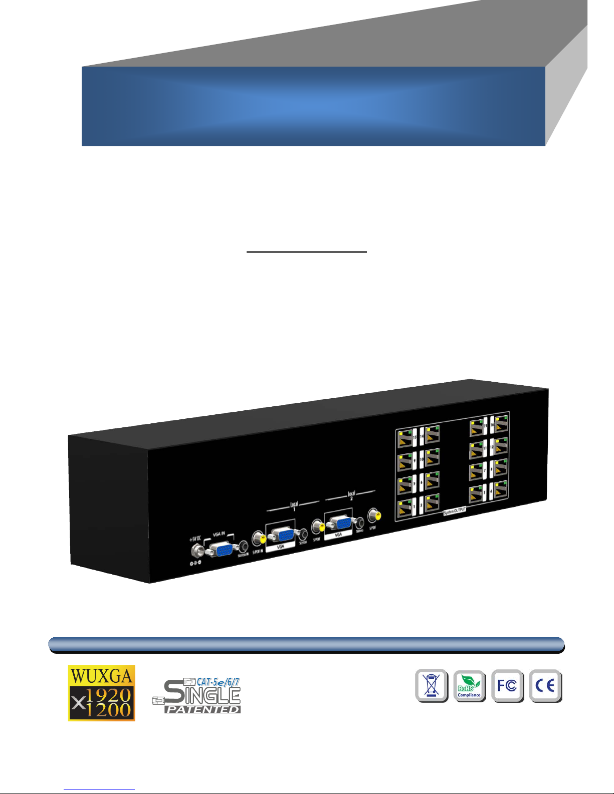
1x12 V GA & Audio over CAT5 Splitter
User Manual
rev: 160322
Made in Taiwan
S
S
P
P--
9
9
1
1
1
1
2
2
Safety and Notice
The SP-9112 1x12 VGA & Audio over CAT5 Splitter has been tested for conformance to safety
regulations and requirements, and has been certified for international use. However, like all
electronic equipments, the SP-9112 should be used with care. Please read and follow the safety
instructions to protect yourself from possible injury and to minimize the risk of damage to the unit.
● Follow all instructions and warnings marked on this unit.
● Do not attempt to service this unit yourself, except where explained in this manual.
● Provide proper ventilation and air circulation and do not use near water.
● Keep objects that might damage the device and assure that the placement of this unit is on a
stable surface.
● Use only the power adapter and power cords and connection cables designed for this unit.
● Do not use liquid or aerosol cleaners to clean this unit. Always unplug the power to the device
before cleaning.
TABLE OF CONTENTS
INTRODUCTION................................................................................................................. 1
FEATURES ......................................................................................................................... 1
PACKAGE CONTENTS ...................................................................................................... 1
SPECIFICATIONS .............................................................................................................. 2
PANEL DESCRIPTIONS ..................................................................................................... 3
HARDWARE INSTALLATION ............................................................................................. 4
CONNECTION DIAGRAM .................................................................................................. 5
NOTICE .............................................................................................................................. 6
PIN DEFINITION ................................................................................................................. 7

INTRODUCTION
The
SP-9112 1x12 VGA & Audio over CAT5 Splitter
wit h only one cost effective Cat-5/5e/6 cable
lets you extend VGA or component video (WUXGA) and stereo/analog audio signals to cover the
distance up to 330m to sixteen VGA & Audio over CAT5 receivers (BPVGARA or BPVGARAD). Built with
two VGA and digital/analog audio loop-outs, local AV receivers can provide extra video and audio
fan-outs through typical VGA, S/PDIF, and analog audio cables. The high bandwidth VGA can be
transmitted up to 65 meters on the local ports.
FEATURES
Supports up to WUXGA (1920x1200@60) to 330m(1000ft)
Supports Analog Stereo Audio and S/PDIF Digital Audio
Adjustable equalization and gain control on Receiver unit
De-skew compensation available for RGB delay control
PACKAGE CONTENTS
1x SP-9112
1x Rack Mounting Kit
1x 5V power supply unit
1x User manual
1

SPECIFICATIONS
Model Name
SP-9112
Technical
Role of usage
1x12 splitter / transmitter [TX]
Video bandwidth
350MHz
Video support
VESA
Supported Resolutions
Up to WUXGA (1920 x1200)
Resolution and Distance
1280x 1024 at 300 meters (1000 feet)
Audio Support
Stereo
Equalization
Continuous analog control
Input Video Signal
1.2 Volts (peak-to-peak)
ESD protection
[1] Human body — ±19kV [air-gap discharge] & ±12kV [contact discharge]
[2] Core chipset — ±8kV
PCB stack-up
4-layer board [impedance control — differential 100Ω; single 50Ω]
Input
1x VGA + 1x 3.5mm + 1x RCA
Output
2x VGA + 2x 3.5mm + 2x RCA + 12x RJ45
VGA connector
HD-15 (15-pin D-sub female)
RJ45 connector
WE/SS 8P8C with 2 LED indicators
3.5mm connector Earphone jack for analog stereo audio
RCA connector
S/PDIF Digital Audio
Mechanical
Housing
Metal enclosure
Dimensions
[L x W x H]
Model
99 x 431 x 88mm
Package
510 x 230 x 70mm [1'8" x 9.1" x 2.8"]
510 x 410 x 252mm [1'8" x 1'4" x 10"]
Weight
Model
1.5kg
Package
2.6kg
Fixedness 2 RU rack-mount case with screws & latch-locking power jack
Power supply
5V 4A DC
Power consumption
20 Watts [max]
Operation temperature 32˚ ~ 104˚F (0˚ to 40˚C)
Storage temperature
--4˚ ~ 140˚F (-20˚ ~ 60˚C)
Relative humidity
20~90% RH [no condensation]
2

PANEL DESCRIPTIONS
Front Panel
1. Audio Format Switch: A push-in button for input audio selection.
( — analog stereo audio; — S/PDIF digital stereo audio)
2. Power: Power on/off indicator.
Rear Panel
3. +5V DC: Latch-locking power jack to connect to a 5V DC power supply unit with a C7 power cord.
4. VGA INPUT: Connect to a VGA source or a component video source (via a VGA-component breakout
cable)
5. Stereo IN: Connect to an analog stereo audio source.
6. S/PDIF IN: Connect to a digital stereo audio source.
7. VGA O UT: Local video output to a VGA display or component video display (via a VGA-component
breakout cable).
8. Stereo OUT: Local audio output to analog stereo audio speakers.
9. S/PDIF OUT: Local audio output to digital stereo audio speakers.
10. VGA SIGNAL OUT: Connect a Cat-5/5e/6 cable to each RJ45 port and link it to the receiving units.
3

HARDWARE INSTALLATION
Broadcasts PC A/V signals to 12 remote displays and two local receivers
1. Switch off all devices, including monitors.
2. Connect the video and audio sources to the SP-9112. For component video source, please
find a VGA-component breakout cable to plug into the VGA IN port.
3. Connect the video displays and audio speakers to the receiving units BPVGARA or
BPVGARAD. For component video display, please find a VGA-component breakout cable
and plug into the VGA OUT port on the receiving units BPVGARA or BPVGARAD.
4. Connect a Cat-5/5e/6 cable to each VGA SIGNAL OUT RJ45 port on the SP-9112 and the
VGA SIGNAL IN RJ45 port on each receiving unit BPVGARA or BPVGARAD. Make sure
these Cat-5/5e/6 cables are tightly connected and not loose.
5. Plug in 5V DC power supply units and power on all devices.
6. If you see the monitor is displaying blurred video or even worse, not displaying at all, please
adjust the EQ and Gain rotary controls on the receiving units BPVGARA or BPVGARAD to
improve the cable ske w. GAIN rotary control is to adjust the g ai n to an ap pr opr i at e l evel for a
range of input signal levels (brightness), and EQ rotary control is to equalize the wave form
of the receiving video signal (sharpness). It is suggested to begin with adjusting the rotary
control of EQ to get the input video displayed first, and then the rotary control of GAIN
according to the video you see on the screen.
7. Adjust RGB delay skew on the receiving unit BPVGARAD to get even better picture quality
for long distance transmission.
4

CONNECTION DIAGRAM
5

NOTICE
1. All the transmission distances are measured using Belden CAT-5e 125MHz Solid cable and
ASTRODESIGN Video Signal Generator VG-859C. The transmission distance is defined as the
distance between the SP-9112 and the remote VGA display.
2. The transmission length is largely affected by the type of Cat-5/5e/6 cables, the type of VGA sources,
and the type of VGA display. The testing result shows solid UTP cables (usually in the form of 300m
[1,000ft] bulk cables) can transmit a lot longer signals than stranded UTP cables (usually in the form of
fixed length patch cords). Shielded STP cables are better suited than unshielded UTP cables. A solid
UTP Cat-5e cable shows longer transmission range than stranded STP Cat-6 cable. For long
extension applications, solid UTP/STP cables are the only viable choice.
3. EIA/TIA-568-B termination (T568B) for Cat-5/5e/6 cables is recommended for better performance.
4. To reduce the interference among the unshielded twisted pairs of wires in Cat-5/5e/6 cable, one can
use shielded STP cables to improve EMI problems, which is worsen in long transmission.
5. Because the quality of the CAT5/6 cables has the major effect on how long the transmission limit can
achieve and how good is the received picture quality, the actual transmission range is subject to one's
choice of Cat-5/5e/6 cables. For desired resolutions greater than 1080i or 1280x1024, a Cat-6 cable is
recommended.
6. The RS-232 channel for all the connected receivers actually share the same path, and therefore the
system designers must be aware of that the feedback after each serial command sent by the source
must only happen once on one remote device or no feedback at all to avoid interfaces from different
receivers!
Performance Guide for HDMI over Category Cable Transmission
Performance rating
Type of category cable
Wiring
Shielding
CAT5
CAT5e
CAT6
Solid
Unshielded (UTP)
Shielded (STP)
Stranded
Unshielded (UTP)
Shielded (STP)
Termination
Please use EIA/TIA-568-B termination (T568B) at any time
6

PIN DEFINITION
VGA / Component
Pin 1 » Pr / Red
Pin 6 » Ground
Pin 11 » Ground
Pin 2 » Y / Green / Composite
Pin 7 » Ground
Pin 12 » Reserved
Pin 3 » Pb / Blue
Pin 8 » Ground
Pin 13 » Horizontal sync
Pin 4 » Ground
Pin 9 » +5V DC
Pin 14 » Vertical sync
Pin 5 » Ground
Pin 10 » Ground
Pin 15 » Reserved
RJ-45 / Category cable
Pair of Cat-5/5e/6 Cable Associated Definition
GREEN
Audio
BLUE
RED channel of VGA
ORANGE
GREEN channel of VGA
BROWN
BLUE channel of VGA
3
10 6 7
11
12
13
14
15
1
2
4
5 8 9
7
 Loading...