

Page 1
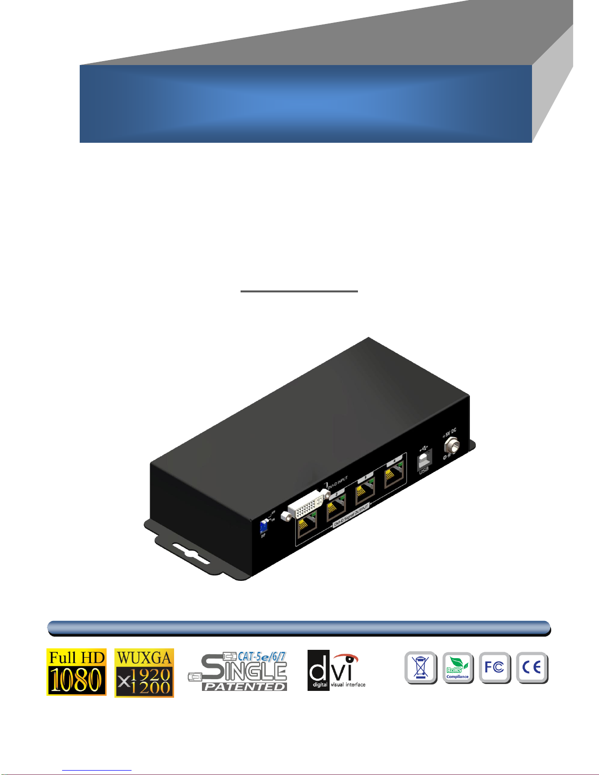
1x4 DVI Splitter over Single Cat.X
with HDCP Support
User Manual
rev: 111209
Made in Taiwan
S
S
P
P--
1
1
0
0
1
1
4
4
Page 2
The SP-1014 1x4 DVI Splitter over Single Cat.X with HDCP Support has been tested for
conformance to safety regulations and requirements, and has been certified for international use.
However, like all electronic equipments, the SP-1014 should be used with care. Please read and
follow the safety instructions to protect yourself from possible injury and to minimize the risk of
damage to the unit.
● Follow all instructions and warnings marked on this unit.
● Do not attempt to service this unit yourself, except where explained in this manual.
● Provide proper ventilation and air circulation and do not use near water.
● Keep objects that might damage the device and assure that the placement of this unit is on a
stable surface.
● Use only the power adapter and power cords and connection cables designed for this unit.
● Do not use liquid or aerosol cleaners to clean this unit. Always unplug the power to the device
before cleaning.
TABLE OF CONTENTS
INTRODUCTION................................................................................................................. 1
FEATURES ......................................................................................................................... 1
PACKAGE CONTENTS ...................................................................................................... 1
SPECIFICATIONS .............................................................................................................. 2
PANEL DESCRIPTIONS ..................................................................................................... 3
HARDWARE INSTALLATION ............................................................................................. 4
CONNECTION DIAGRAM .................................................................................................. 4
DIP SWITCH ....................................................................................................................... 5
PIN DEFINITION ................................................................................................................. 6
NOTICE .............................................................................................................................. 7
WARRANTY ....................................................................................................................... 8
Page 3
1
INTRODUCTION
The
SP-1014 1x4 DVI Splitter over Single Cat.X with HDCP Support
provides the most flexible
solution by which the high definition video and high quality audio can be transmitted to different locations
over a long distance. The devices are cascadable, allowing you to extend DVI compliant displays almost
anywhere. The input DVI source can be duplicated and distributed to up to 4 DVI-enabled displays
through cost effective Cat-5/5e/6 cables and Cat.X receiver (CV-711) and/or mini-receivers (CV-711S).
FEATURES
● HDMI founder Silicon Image chipsets embedded for superior compatibility and reliability
● DVI 1.0 compliant
● Supports HDCP
● Supports default DVI EDID and has the ability to learn the EDID of displays
● Extends up to 30m (100ft) at UXGA 1600x1200@60Hz
● Extends up to 60m (200ft) at 1024x768@60Hz
● Allows cascading
● Perfectly integrated with other DVI over CAT5 series products
● Wall mountable
PACKAGE CONTENTS
● 1x SP-1014
● 1x DC 5V 4A in-line with C7 power cord
● 1x User Manual
The length depends on the characteristics and quality of the cables. Higher resolutions and
longer transmission distances require low skew cables (<25ns/100m) for best performance.
Unshielded CAT6 with metal RJ45 connectors is recommended.
Page 4
2
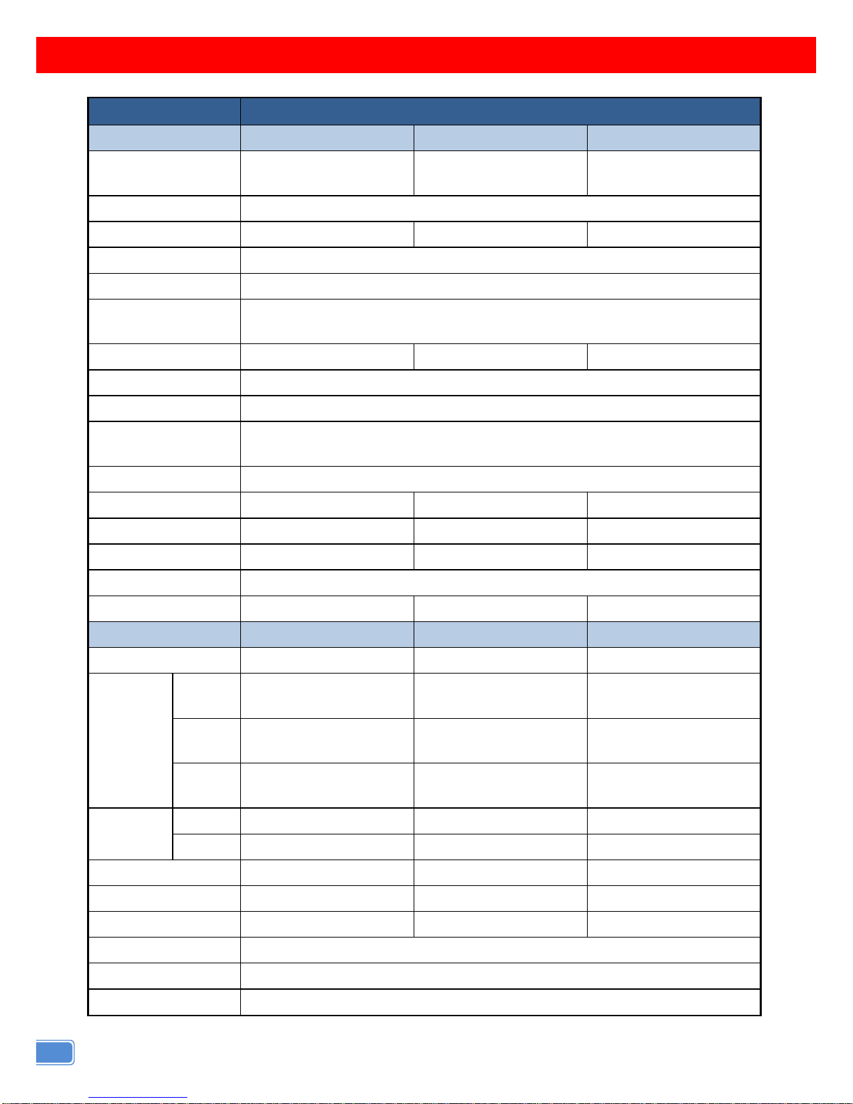
SPECIFICATIONS
Model Name
SP-1014
Technical SP-1014[TX]
CV-17[RX]
CV-117[RX]
Role of usage
1x4 Distribution Amplifier
Transmitter [TX]
Receiver
[long range RX]
Receiver
[short range RX]
DVI compliance
DVI 1.1
HDCP compliance
No
Yes
Yes
Video bandwidth
Single-link 165MHz [4.95Gbps]
Video support
Up to (Single) WUXGA 1920 × 1200 @ 60 Hz
Video transmission
over category cable
With CV-17 -RX: 30m (100ft) at 1600x1200 60m (200ft) at 1024x768
With CV-117: 15m (50ft) at 1600x1200 30m (100ft) at 1024x768
Equalization
N/A
8-level digital
None
Input TMDS signal
1.2 Volts [peak-to-peak]
Input DDC signal
5 Volts [peak-to-peak, TTL]
ESD protection
[1] Human body model — ±19kV [air-gap discharge] & ±12kV [contact discharge]
[2] Core chipset — ±8kV
PCB stack-up
4-layer board [impedance control — differential 100Ω; single 50Ω]
Input
1x DVI
1x RJ45
1x RJ45
Output
4x RJ45
1x DVI
1x DVI
DVI connector
DVI-I [29-pin female]
DVI-I A [29-pin female]
DVI-D [25-pin male]
RJ45 connector
WE/SS 8P8C with 2 LED indicators
Rotary switch
2-pin
None
None
Mechanical
SP-1014[TX]
CV-17[RX]
CV-117[RX]
Housing
Metal enclosure
Metal enclosure
Plastic molding
Dimensions
[L x W x H]
Model
215 x 85 x 40mm
[8.5" x 3.3" x 1.6"]
82 x 62 x 24mm
[3.2" x 2.4" x 1"]
40 x 50 x 20mm
[1.6" x 2" x 0.8"]
Package
330 x 200 x 95mm
[1'1" x 7.9" x 3.7"]
170 x 115 x 40mm
[6.7" x 4.5" x 1.6"]
Carton
495 x 440 x 380mm
[1'7" x 1'5" x 1'3"]
450 x 370 x 300mm
[1'5.7" x 1'2.6" x 11.8"]
Weight
Model
525 [1.2 lbs]
182g [6.4oz]
50g [1.8oz]
Package
985 [2.2 lbs]
140g [5oz]
Fixedness
Wall-mount with screws
Wall-mount with screws
Direct plug-in
Power supply
5V 4A DC
5V 2A DC
None
Power consumption
10 Watts [max]
1 Watt [max]
0.5 Watt [max]
Operation temperature
0~40°C [32~104°F]
Storage temperature
-20~60°C [-4~140°F]
Relative humidity
20~90% RH [no condensation]
Page 5
3
PANEL DESCRIPTIONS
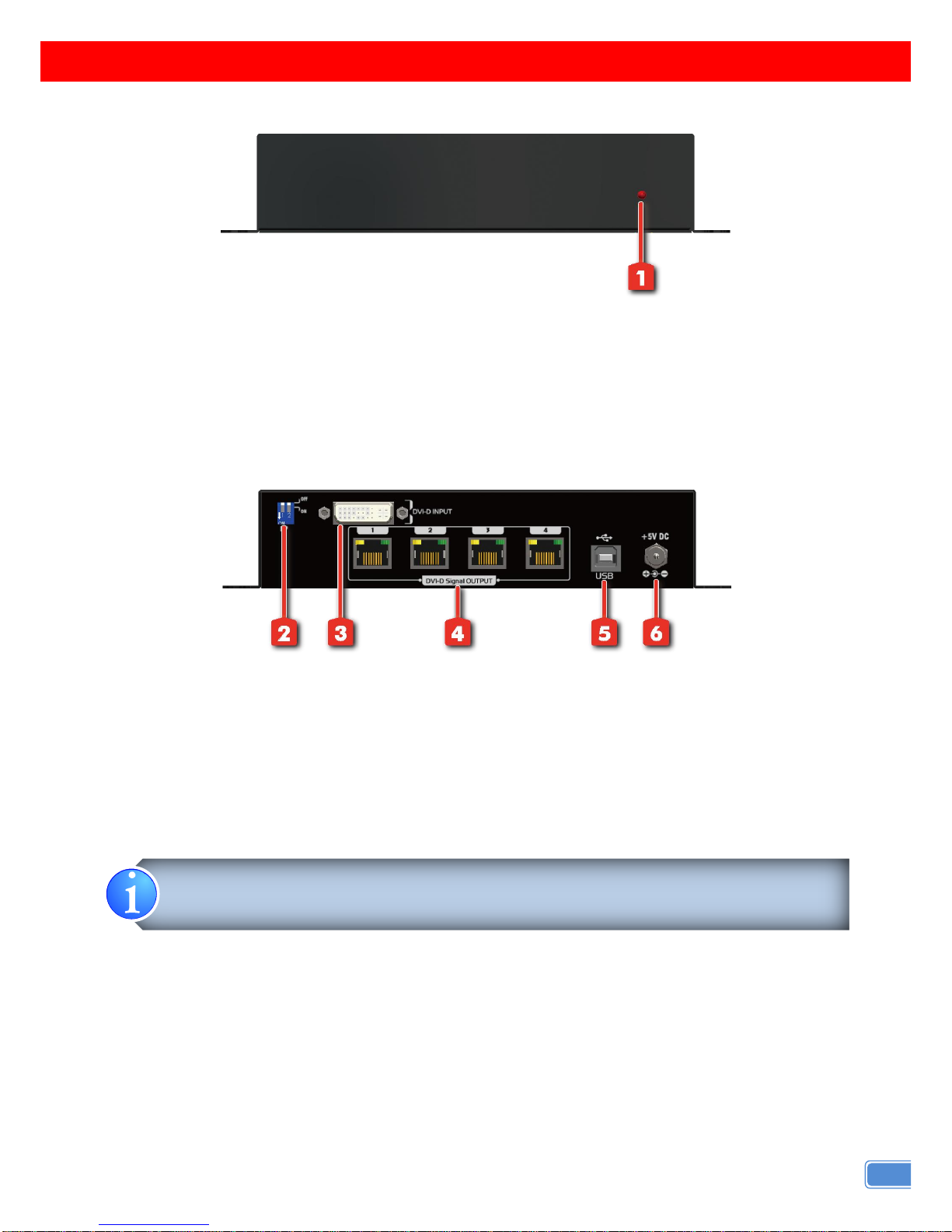
Front Panel
1. Power indicator LED
Rear Panel
2. DIP SWITCH: see more detail in the next page
3. DVI-D INPUT: connect to one DVI source here
4. DVI-D Signal OUTPUT 1~4: link to each DVI display via a Cat-5/5e/6 cable with a DVI over Cat.X
receiver CV-711 or CV-711S.
5. USB: For firmware update use only
6. +5V DC: interlocking power jack for 5V DC power supply unit
When the connected DVI / HDMI monitor is verified as DVI or HDMI and HDCP compliant,
the corresponding green LED will blink.
Page 6
4
HARDWARE INSTALLATION
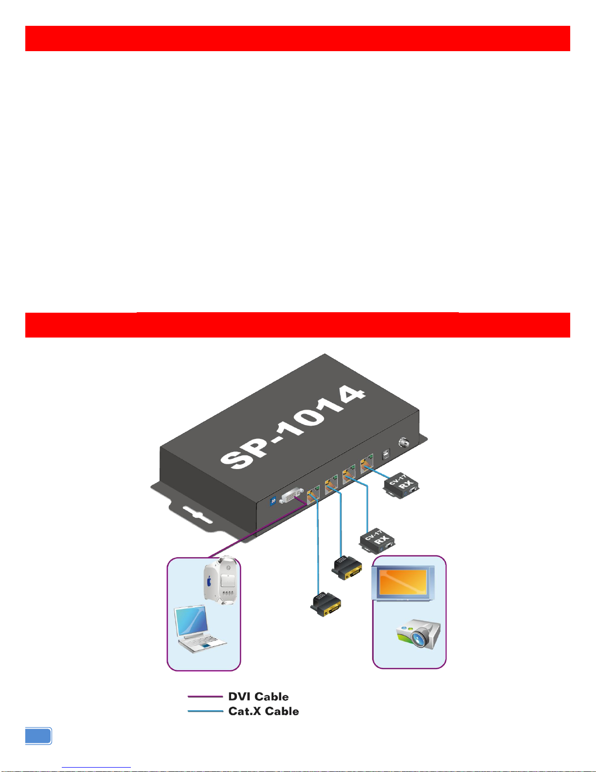
Broadcasts DVI signals to 4 remote displays from one video source
1. Switch off all devices, including displays.
2. Connect the DVI source to the DVI-D INPUT port.
3. Connect the receivers (CV-711 or CV-711S) via solid Cat-5/5e/6 cables to each DVI-D Signal
OUTPUT port.
4. Plug in the 5V 4A DC interlocking power supply unit.
5. Power on the DVI displays.
6. Power on the DVI source.
CONNECTION DIAGRAM
Page 7
5
DIP SWITCH
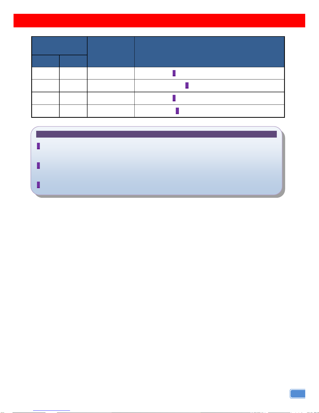
DIP Switch
Position
EDID Mode
Description
Pin#1
Pin#2
OFF []
OFF []
Up to 1920x1080
Default Mode 1
1 – EDID preferred timing is 1920x1080
OFF []
ON []
Up to 1024x768
Default Safe Mode 1
– EDID preferred timing is 1024x768
ON []
OFF []
Up to 1680x1050
Default Mode 1
2 – EDID preferred timing is 1680x1050
ON []
ON []
Learn Display
EDID Learning 2 Mode
– for learning EDID from the display
Note
1 If you want to change default EDID Mode, please set DIP switch position which you want and
power cycle the device.
2 If you want to learn the display EDID, please connect display DVI connector to machine DVI-IN
connector and set DIP switch to ON-ON, then power cycle the device and wait for 5-10 seconds.
3 Unless you want to change the EDID, do not change the DIP setting.
Page 8
6
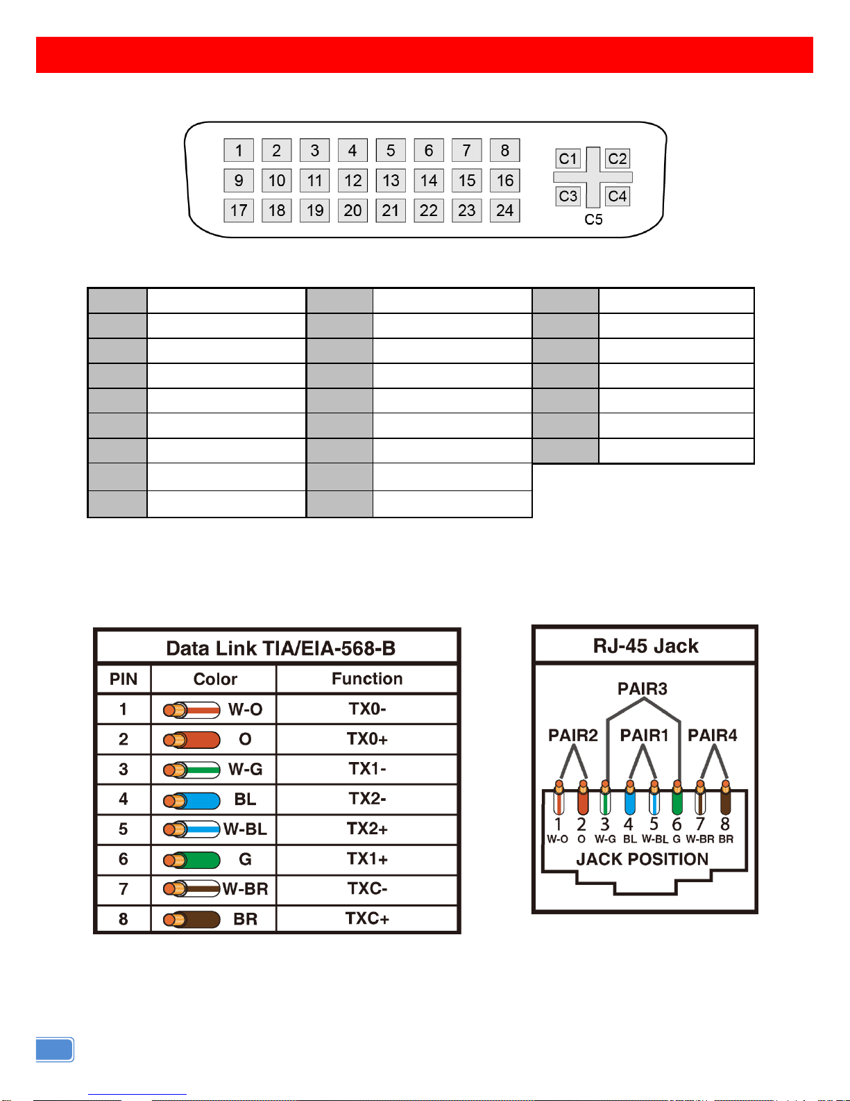
PIN DEFINITION
DVI
A female DVI-I socket from the front
Pin 1
TMDS Data 2-
Pin 10
TMDS Data 1+
Pin 18
TMDS data 0+
Pin 2
TMDS Data 2+
Pin 11
TMDS Data 1/3 shield
Pin 19
TMDS data 0/5 shield
Pin 3
TMDS Data 2/4 shield
Pin 12
TMDS Data 3-
Pin 20
TMDS data 5-
Pin 4
TMDS Data 4-
Pin 13
TMDS Data 3+
Pin 21
TMDS data 5+
Pin 5
TMDS Data 4+
Pin 14
+5V
Pin 22
TMDS data 5+
Pin 6
DDC clock
Pin 15
Ground
Pin 23
TMDS clock+
Pin 7
DDC data
Pin 16
Hot plug detect
Pin 24
TMDS clock-
Pin 8
Analog vertical sync
Pin 16
Hot plug detect
Pin 9
TMDS Data 1-
Pin 17
TMDS data 0-
RJ45 / Cat.X
Page 9
7
NOTICE
1. If the DVI device requires the EDID information, please use EDID Reader/Writer to retrieve and
provide DVI display EDID information.
2. All DVI over Cat.X transmission distances are measured using Belden 1583A CAT5e 125MHz UTP
cable and ASTRODESIGN Video Signal Generator VG-859C.
3. The transmission length is largely affected by the type of Cat-5/5e/6 cables, the type of DVI sources,
and the type of DVI display. The testing result shows solid UTP cables (usually in the form of 330m
[1,000ft] bulk cables) can transmit a lot longer signals than stranded UTP cables (usually in the form of
fixed length patch cords). Shielded STP cables are better suited than unshielded UTP cables. A solid
UTP Cat-5e cable shows longer transmission range than stranded STP Cat-6 cable. For long
extension applications, solid UTP/STP cables are the only viable choice.
4. EIA/TIA-568-B termination (T568B) for Cat-5/5e/6 cables is recommended for better performance.
5. To reduce the interference among the unshielded twisted pairs of wires in Cat-5/5e/6 cable, one can
use shielded STP cables to improve EMI problems, which is worsen in long transmission.
6. Because the quality of the CAT5/6 cables has the major effect on how long the transmission limit can
achieve and how good is the received picture quality, the actual transmission range is subject to one's
choice of Cat-5/5e/6 cables. For desired resolutions greater than 1080i or 1280x1024, a Cat-6 cable is
recommended.
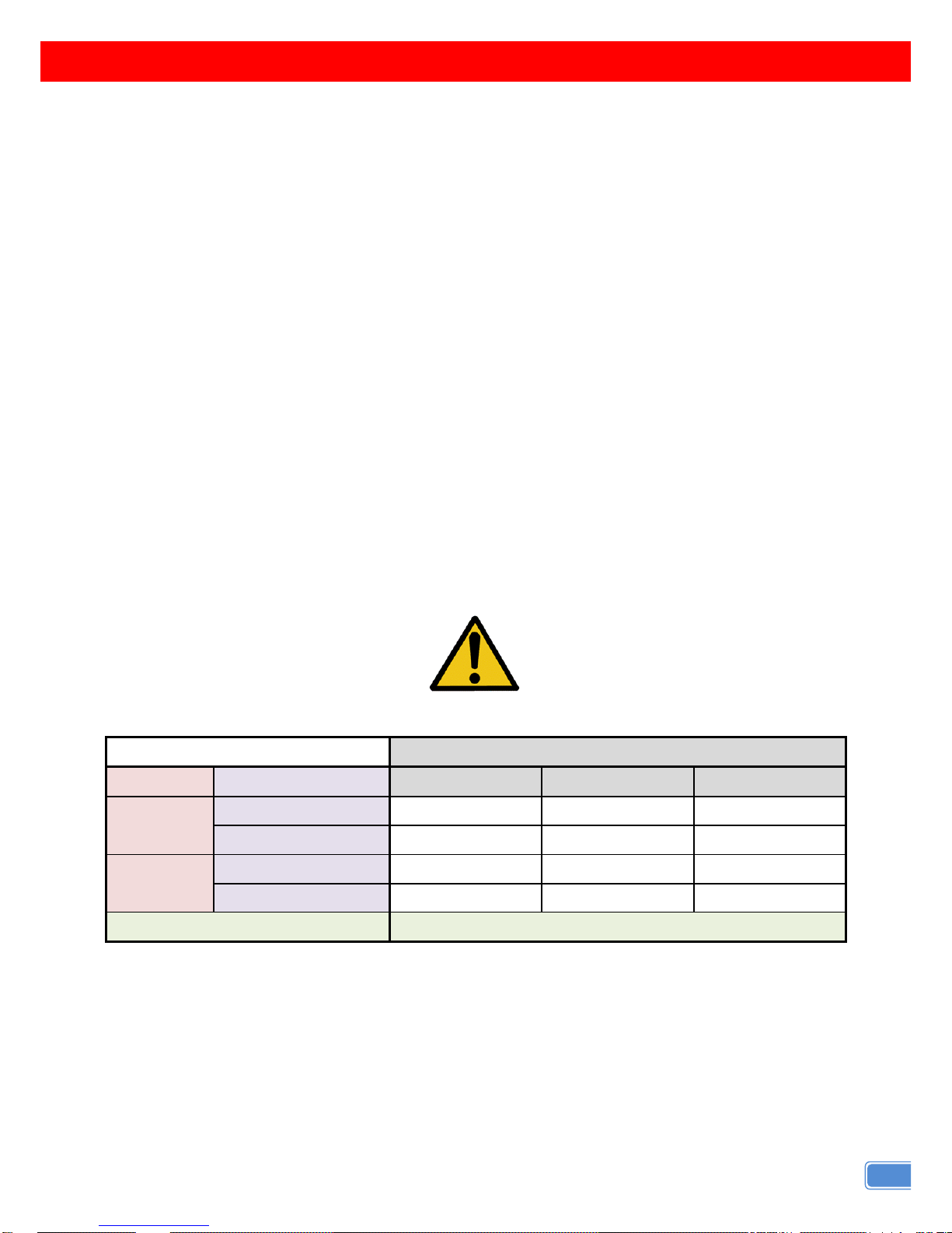
Performance Guide for HDMI over Category Cable Transmission
Performance rating
Type of category cable
Wiring
Shielding
CAT5
CAT5e
CAT6
Solid
Unshielded (UTP)
Shielded (STP)
Stranded
Unshielded (UTP)
Shielded (STP)
Termination
Please use EIA/TIA-568-B termination (T568B) at any time
Page 10

8
WARRANTY
The SELLER warrants the
SP-1014 1x4 DVI Splitter over Single Cat.X with HDCP Support
free
from defects in the material and workmanship for 1 year from the date of purchase from the SELLER or
an authorized dealer. Should this product fail to be in good working order within 1 year warranty period,
The SELLER, at its option, repair or replace the unit, provided that the unit has not been subjected to
accident, disaster, abuse or any unauthorized modifications including static discharge and power surge.
This warranty is offered by the SELLER for its BUYER with direct transaction only. This warranty is void if
the warranty seal on the metal housing is broken.
Unit that fails under conditions other than those covered will be repaired at the current price of parts
and labor in effect at the time of repair. Such repairs are warranted for 90 days from the day of reshipment
to the BUYER. If the unit is delivered by mail, customers agree to insure the unit or assume the risk of loss
or damage in transit. Under no circumstances will a unit be accepted without a return authorization
number.
The warranty is in lieu of all other warranties expressed or implied, including without limitations, any
other implied warranty or fitness or merchantability for any particular purpose, all of which are expressly
disclaimed.
Proof of sale may be required in order to claim warranty. Customers outside Taiwan are responsible
for shipping charges to and from the SELLER. Cables and power adapters are limited to a 30 day
warranty and must be free from any markings, scratches, and neatly coiled.
The content of this manual has been carefully checked and is believed to be accurate. However, The
SELLER assumes no responsibility for any inaccuracies that may be contained in this manual. The
SELLER will NOT be liable for direct, indirect, incidental, special, or consequential damages resulting
from any defect or omission in this manual, even if advised of the possibility of such damages. Also, the
technical information contained herein regarding the
SP-1014
features and specifications is subject to
change without further notice.
 Loading...